US10745006B2 - Managing automated driving complexity of the forward path using perception system measures - Google Patents
Managing automated driving complexity of the forward path using perception system measures Download PDFInfo
- Publication number
- US10745006B2 US10745006B2 US15/886,492 US201815886492A US10745006B2 US 10745006 B2 US10745006 B2 US 10745006B2 US 201815886492 A US201815886492 A US 201815886492A US 10745006 B2 US10745006 B2 US 10745006B2
- Authority
- US
- United States
- Prior art keywords
- vehicle
- complexity
- computing system
- sensors
- computing
- Prior art date
- Legal status (The legal status is an assumption and is not a legal conclusion. Google has not performed a legal analysis and makes no representation as to the accuracy of the status listed.)
- Active, expires
Links
- 230000008447 perception Effects 0.000 title description 2
- 238000000034 method Methods 0.000 claims abstract description 43
- 230000004044 response Effects 0.000 claims abstract description 22
- 230000007613 environmental effect Effects 0.000 claims description 31
- 230000004927 fusion Effects 0.000 claims description 24
- 238000004891 communication Methods 0.000 claims description 15
- 238000010801 machine learning Methods 0.000 claims description 13
- 238000012731 temporal analysis Methods 0.000 claims description 11
- 238000000700 time series analysis Methods 0.000 claims description 11
- 238000004422 calculation algorithm Methods 0.000 claims description 9
- 230000002776 aggregation Effects 0.000 claims description 4
- 238000004220 aggregation Methods 0.000 claims description 4
- 238000012358 sourcing Methods 0.000 claims description 4
- 230000006870 function Effects 0.000 description 32
- 239000000243 solution Substances 0.000 description 29
- 238000003860 storage Methods 0.000 description 21
- 230000009471 action Effects 0.000 description 20
- 238000001514 detection method Methods 0.000 description 17
- 230000015654 memory Effects 0.000 description 12
- 238000010586 diagram Methods 0.000 description 10
- 238000012545 processing Methods 0.000 description 9
- 238000004458 analytical method Methods 0.000 description 8
- 238000012544 monitoring process Methods 0.000 description 6
- 230000001133 acceleration Effects 0.000 description 5
- 230000003044 adaptive effect Effects 0.000 description 4
- 230000005540 biological transmission Effects 0.000 description 4
- 238000004590 computer program Methods 0.000 description 4
- 230000003068 static effect Effects 0.000 description 4
- 230000008901 benefit Effects 0.000 description 3
- 238000005516 engineering process Methods 0.000 description 3
- 230000003287 optical effect Effects 0.000 description 3
- 230000001953 sensory effect Effects 0.000 description 3
- 238000003491 array Methods 0.000 description 2
- 238000013528 artificial neural network Methods 0.000 description 2
- 238000010276 construction Methods 0.000 description 2
- 238000013461 design Methods 0.000 description 2
- 230000008569 process Effects 0.000 description 2
- 230000001902 propagating effect Effects 0.000 description 2
- 238000005067 remediation Methods 0.000 description 2
- 230000007704 transition Effects 0.000 description 2
- 102100034112 Alkyldihydroxyacetonephosphate synthase, peroxisomal Human genes 0.000 description 1
- RYGMFSIKBFXOCR-UHFFFAOYSA-N Copper Chemical compound [Cu] RYGMFSIKBFXOCR-UHFFFAOYSA-N 0.000 description 1
- 101000799143 Homo sapiens Alkyldihydroxyacetonephosphate synthase, peroxisomal Proteins 0.000 description 1
- 238000000848 angular dependent Auger electron spectroscopy Methods 0.000 description 1
- 238000013459 approach Methods 0.000 description 1
- 238000004364 calculation method Methods 0.000 description 1
- 238000012512 characterization method Methods 0.000 description 1
- 229910052802 copper Inorganic materials 0.000 description 1
- 239000010949 copper Substances 0.000 description 1
- 238000013500 data storage Methods 0.000 description 1
- 230000001419 dependent effect Effects 0.000 description 1
- 238000011161 development Methods 0.000 description 1
- 239000012895 dilution Substances 0.000 description 1
- 238000010790 dilution Methods 0.000 description 1
- 239000000835 fiber Substances 0.000 description 1
- 230000014509 gene expression Effects 0.000 description 1
- 230000006872 improvement Effects 0.000 description 1
- 230000010354 integration Effects 0.000 description 1
- 230000003993 interaction Effects 0.000 description 1
- 238000004519 manufacturing process Methods 0.000 description 1
- 239000000463 material Substances 0.000 description 1
- 230000000116 mitigating effect Effects 0.000 description 1
- 238000012986 modification Methods 0.000 description 1
- 230000004048 modification Effects 0.000 description 1
- 230000002441 reversible effect Effects 0.000 description 1
- 239000004065 semiconductor Substances 0.000 description 1
- 230000006403 short-term memory Effects 0.000 description 1
- 239000000725 suspension Substances 0.000 description 1
- 230000002123 temporal effect Effects 0.000 description 1
- 238000012360 testing method Methods 0.000 description 1
Images


Classifications
-
- G—PHYSICS
- G06—COMPUTING; CALCULATING OR COUNTING
- G06N—COMPUTING ARRANGEMENTS BASED ON SPECIFIC COMPUTATIONAL MODELS
- G06N3/00—Computing arrangements based on biological models
- G06N3/02—Neural networks
- G06N3/08—Learning methods
-
- B—PERFORMING OPERATIONS; TRANSPORTING
- B60—VEHICLES IN GENERAL
- B60W—CONJOINT CONTROL OF VEHICLE SUB-UNITS OF DIFFERENT TYPE OR DIFFERENT FUNCTION; CONTROL SYSTEMS SPECIALLY ADAPTED FOR HYBRID VEHICLES; ROAD VEHICLE DRIVE CONTROL SYSTEMS FOR PURPOSES NOT RELATED TO THE CONTROL OF A PARTICULAR SUB-UNIT
- B60W30/00—Purposes of road vehicle drive control systems not related to the control of a particular sub-unit, e.g. of systems using conjoint control of vehicle sub-units, or advanced driver assistance systems for ensuring comfort, stability and safety or drive control systems for propelling or retarding the vehicle
- B60W30/08—Active safety systems predicting or avoiding probable or impending collision or attempting to minimise its consequences
- B60W30/09—Taking automatic action to avoid collision, e.g. braking and steering
-
- B—PERFORMING OPERATIONS; TRANSPORTING
- B60—VEHICLES IN GENERAL
- B60W—CONJOINT CONTROL OF VEHICLE SUB-UNITS OF DIFFERENT TYPE OR DIFFERENT FUNCTION; CONTROL SYSTEMS SPECIALLY ADAPTED FOR HYBRID VEHICLES; ROAD VEHICLE DRIVE CONTROL SYSTEMS FOR PURPOSES NOT RELATED TO THE CONTROL OF A PARTICULAR SUB-UNIT
- B60W30/00—Purposes of road vehicle drive control systems not related to the control of a particular sub-unit, e.g. of systems using conjoint control of vehicle sub-units, or advanced driver assistance systems for ensuring comfort, stability and safety or drive control systems for propelling or retarding the vehicle
- B60W30/08—Active safety systems predicting or avoiding probable or impending collision or attempting to minimise its consequences
- B60W30/095—Predicting travel path or likelihood of collision
- B60W30/0956—Predicting travel path or likelihood of collision the prediction being responsive to traffic or environmental parameters
-
- B—PERFORMING OPERATIONS; TRANSPORTING
- B60—VEHICLES IN GENERAL
- B60W—CONJOINT CONTROL OF VEHICLE SUB-UNITS OF DIFFERENT TYPE OR DIFFERENT FUNCTION; CONTROL SYSTEMS SPECIALLY ADAPTED FOR HYBRID VEHICLES; ROAD VEHICLE DRIVE CONTROL SYSTEMS FOR PURPOSES NOT RELATED TO THE CONTROL OF A PARTICULAR SUB-UNIT
- B60W30/00—Purposes of road vehicle drive control systems not related to the control of a particular sub-unit, e.g. of systems using conjoint control of vehicle sub-units, or advanced driver assistance systems for ensuring comfort, stability and safety or drive control systems for propelling or retarding the vehicle
- B60W30/10—Path keeping
- B60W30/12—Lane keeping
-
- B—PERFORMING OPERATIONS; TRANSPORTING
- B60—VEHICLES IN GENERAL
- B60W—CONJOINT CONTROL OF VEHICLE SUB-UNITS OF DIFFERENT TYPE OR DIFFERENT FUNCTION; CONTROL SYSTEMS SPECIALLY ADAPTED FOR HYBRID VEHICLES; ROAD VEHICLE DRIVE CONTROL SYSTEMS FOR PURPOSES NOT RELATED TO THE CONTROL OF A PARTICULAR SUB-UNIT
- B60W50/00—Details of control systems for road vehicle drive control not related to the control of a particular sub-unit, e.g. process diagnostic or vehicle driver interfaces
- B60W50/0097—Predicting future conditions
-
- B—PERFORMING OPERATIONS; TRANSPORTING
- B60—VEHICLES IN GENERAL
- B60W—CONJOINT CONTROL OF VEHICLE SUB-UNITS OF DIFFERENT TYPE OR DIFFERENT FUNCTION; CONTROL SYSTEMS SPECIALLY ADAPTED FOR HYBRID VEHICLES; ROAD VEHICLE DRIVE CONTROL SYSTEMS FOR PURPOSES NOT RELATED TO THE CONTROL OF A PARTICULAR SUB-UNIT
- B60W50/00—Details of control systems for road vehicle drive control not related to the control of a particular sub-unit, e.g. process diagnostic or vehicle driver interfaces
- B60W50/06—Improving the dynamic response of the control system, e.g. improving the speed of regulation or avoiding hunting or overshoot
-
- B—PERFORMING OPERATIONS; TRANSPORTING
- B60—VEHICLES IN GENERAL
- B60W—CONJOINT CONTROL OF VEHICLE SUB-UNITS OF DIFFERENT TYPE OR DIFFERENT FUNCTION; CONTROL SYSTEMS SPECIALLY ADAPTED FOR HYBRID VEHICLES; ROAD VEHICLE DRIVE CONTROL SYSTEMS FOR PURPOSES NOT RELATED TO THE CONTROL OF A PARTICULAR SUB-UNIT
- B60W50/00—Details of control systems for road vehicle drive control not related to the control of a particular sub-unit, e.g. process diagnostic or vehicle driver interfaces
- B60W50/08—Interaction between the driver and the control system
- B60W50/14—Means for informing the driver, warning the driver or prompting a driver intervention
-
- B—PERFORMING OPERATIONS; TRANSPORTING
- B60—VEHICLES IN GENERAL
- B60W—CONJOINT CONTROL OF VEHICLE SUB-UNITS OF DIFFERENT TYPE OR DIFFERENT FUNCTION; CONTROL SYSTEMS SPECIALLY ADAPTED FOR HYBRID VEHICLES; ROAD VEHICLE DRIVE CONTROL SYSTEMS FOR PURPOSES NOT RELATED TO THE CONTROL OF A PARTICULAR SUB-UNIT
- B60W60/00—Drive control systems specially adapted for autonomous road vehicles
- B60W60/001—Planning or execution of driving tasks
- B60W60/0015—Planning or execution of driving tasks specially adapted for safety
- B60W60/0018—Planning or execution of driving tasks specially adapted for safety by employing degraded modes, e.g. reducing speed, in response to suboptimal conditions
-
- B—PERFORMING OPERATIONS; TRANSPORTING
- B60—VEHICLES IN GENERAL
- B60W—CONJOINT CONTROL OF VEHICLE SUB-UNITS OF DIFFERENT TYPE OR DIFFERENT FUNCTION; CONTROL SYSTEMS SPECIALLY ADAPTED FOR HYBRID VEHICLES; ROAD VEHICLE DRIVE CONTROL SYSTEMS FOR PURPOSES NOT RELATED TO THE CONTROL OF A PARTICULAR SUB-UNIT
- B60W60/00—Drive control systems specially adapted for autonomous road vehicles
- B60W60/005—Handover processes
- B60W60/0053—Handover processes from vehicle to occupant
-
- G—PHYSICS
- G05—CONTROLLING; REGULATING
- G05D—SYSTEMS FOR CONTROLLING OR REGULATING NON-ELECTRIC VARIABLES
- G05D1/00—Control of position, course or altitude of land, water, air, or space vehicles, e.g. automatic pilot
- G05D1/02—Control of position or course in two dimensions
- G05D1/021—Control of position or course in two dimensions specially adapted to land vehicles
- G05D1/0212—Control of position or course in two dimensions specially adapted to land vehicles with means for defining a desired trajectory
- G05D1/0221—Control of position or course in two dimensions specially adapted to land vehicles with means for defining a desired trajectory involving a learning process
-
- G—PHYSICS
- G06—COMPUTING; CALCULATING OR COUNTING
- G06F—ELECTRIC DIGITAL DATA PROCESSING
- G06F18/00—Pattern recognition
- G06F18/20—Analysing
- G06F18/25—Fusion techniques
- G06F18/251—Fusion techniques of input or preprocessed data
-
- G—PHYSICS
- G06—COMPUTING; CALCULATING OR COUNTING
- G06N—COMPUTING ARRANGEMENTS BASED ON SPECIFIC COMPUTATIONAL MODELS
- G06N20/00—Machine learning
-
- G—PHYSICS
- G06—COMPUTING; CALCULATING OR COUNTING
- G06N—COMPUTING ARRANGEMENTS BASED ON SPECIFIC COMPUTATIONAL MODELS
- G06N3/00—Computing arrangements based on biological models
- G06N3/02—Neural networks
- G06N3/04—Architecture, e.g. interconnection topology
- G06N3/044—Recurrent networks, e.g. Hopfield networks
-
- G06N3/0445—
-
- G—PHYSICS
- G06—COMPUTING; CALCULATING OR COUNTING
- G06V—IMAGE OR VIDEO RECOGNITION OR UNDERSTANDING
- G06V10/00—Arrangements for image or video recognition or understanding
- G06V10/70—Arrangements for image or video recognition or understanding using pattern recognition or machine learning
- G06V10/764—Arrangements for image or video recognition or understanding using pattern recognition or machine learning using classification, e.g. of video objects
-
- G—PHYSICS
- G06—COMPUTING; CALCULATING OR COUNTING
- G06V—IMAGE OR VIDEO RECOGNITION OR UNDERSTANDING
- G06V10/00—Arrangements for image or video recognition or understanding
- G06V10/70—Arrangements for image or video recognition or understanding using pattern recognition or machine learning
- G06V10/77—Processing image or video features in feature spaces; using data integration or data reduction, e.g. principal component analysis [PCA] or independent component analysis [ICA] or self-organising maps [SOM]; Blind source separation
- G06V10/80—Fusion, i.e. combining data from various sources at the sensor level, preprocessing level, feature extraction level or classification level
- G06V10/803—Fusion, i.e. combining data from various sources at the sensor level, preprocessing level, feature extraction level or classification level of input or preprocessed data
-
- G—PHYSICS
- G06—COMPUTING; CALCULATING OR COUNTING
- G06V—IMAGE OR VIDEO RECOGNITION OR UNDERSTANDING
- G06V10/00—Arrangements for image or video recognition or understanding
- G06V10/70—Arrangements for image or video recognition or understanding using pattern recognition or machine learning
- G06V10/82—Arrangements for image or video recognition or understanding using pattern recognition or machine learning using neural networks
-
- G—PHYSICS
- G06—COMPUTING; CALCULATING OR COUNTING
- G06V—IMAGE OR VIDEO RECOGNITION OR UNDERSTANDING
- G06V20/00—Scenes; Scene-specific elements
- G06V20/50—Context or environment of the image
- G06V20/56—Context or environment of the image exterior to a vehicle by using sensors mounted on the vehicle
-
- B—PERFORMING OPERATIONS; TRANSPORTING
- B60—VEHICLES IN GENERAL
- B60W—CONJOINT CONTROL OF VEHICLE SUB-UNITS OF DIFFERENT TYPE OR DIFFERENT FUNCTION; CONTROL SYSTEMS SPECIALLY ADAPTED FOR HYBRID VEHICLES; ROAD VEHICLE DRIVE CONTROL SYSTEMS FOR PURPOSES NOT RELATED TO THE CONTROL OF A PARTICULAR SUB-UNIT
- B60W50/00—Details of control systems for road vehicle drive control not related to the control of a particular sub-unit, e.g. process diagnostic or vehicle driver interfaces
- B60W2050/0062—Adapting control system settings
- B60W2050/0075—Automatic parameter input, automatic initialising or calibrating means
-
- B—PERFORMING OPERATIONS; TRANSPORTING
- B60—VEHICLES IN GENERAL
- B60W—CONJOINT CONTROL OF VEHICLE SUB-UNITS OF DIFFERENT TYPE OR DIFFERENT FUNCTION; CONTROL SYSTEMS SPECIALLY ADAPTED FOR HYBRID VEHICLES; ROAD VEHICLE DRIVE CONTROL SYSTEMS FOR PURPOSES NOT RELATED TO THE CONTROL OF A PARTICULAR SUB-UNIT
- B60W50/00—Details of control systems for road vehicle drive control not related to the control of a particular sub-unit, e.g. process diagnostic or vehicle driver interfaces
- B60W50/06—Improving the dynamic response of the control system, e.g. improving the speed of regulation or avoiding hunting or overshoot
- B60W2050/065—Improving the dynamic response of the control system, e.g. improving the speed of regulation or avoiding hunting or overshoot by reducing the computational load on the digital processor of the control computer
-
- B—PERFORMING OPERATIONS; TRANSPORTING
- B60—VEHICLES IN GENERAL
- B60W—CONJOINT CONTROL OF VEHICLE SUB-UNITS OF DIFFERENT TYPE OR DIFFERENT FUNCTION; CONTROL SYSTEMS SPECIALLY ADAPTED FOR HYBRID VEHICLES; ROAD VEHICLE DRIVE CONTROL SYSTEMS FOR PURPOSES NOT RELATED TO THE CONTROL OF A PARTICULAR SUB-UNIT
- B60W50/00—Details of control systems for road vehicle drive control not related to the control of a particular sub-unit, e.g. process diagnostic or vehicle driver interfaces
- B60W50/08—Interaction between the driver and the control system
- B60W50/14—Means for informing the driver, warning the driver or prompting a driver intervention
- B60W2050/143—Alarm means
-
- B—PERFORMING OPERATIONS; TRANSPORTING
- B60—VEHICLES IN GENERAL
- B60W—CONJOINT CONTROL OF VEHICLE SUB-UNITS OF DIFFERENT TYPE OR DIFFERENT FUNCTION; CONTROL SYSTEMS SPECIALLY ADAPTED FOR HYBRID VEHICLES; ROAD VEHICLE DRIVE CONTROL SYSTEMS FOR PURPOSES NOT RELATED TO THE CONTROL OF A PARTICULAR SUB-UNIT
- B60W2556/00—Input parameters relating to data
- B60W2556/10—Historical data
-
- B—PERFORMING OPERATIONS; TRANSPORTING
- B60—VEHICLES IN GENERAL
- B60W—CONJOINT CONTROL OF VEHICLE SUB-UNITS OF DIFFERENT TYPE OR DIFFERENT FUNCTION; CONTROL SYSTEMS SPECIALLY ADAPTED FOR HYBRID VEHICLES; ROAD VEHICLE DRIVE CONTROL SYSTEMS FOR PURPOSES NOT RELATED TO THE CONTROL OF A PARTICULAR SUB-UNIT
- B60W60/00—Drive control systems specially adapted for autonomous road vehicles
- B60W60/005—Handover processes
- B60W60/0059—Estimation of the risk associated with autonomous or manual driving, e.g. situation too complex, sensor failure or driver incapacity
Definitions
- the subject disclosure generally relates to an automated driving system for a vehicle, and particularly to using perception system complexity information to support conditional and high automation levels.
- Autonomous vehicles can operate in various operational modes. For example, in a “fully-automated” operational mode (sometimes referred to as Level 5 automation by National Highway Transportation Safety Agency (NHTSA)) a computing system is used to navigate and/or maneuver the vehicle along a travel route with no input from a human driver. In a “semi-automated” operational mode (Level 3 automation per NHTSA), the vehicle can perform full self-driving functions, but may need human intervention in various situations or may request the driver to take control (with some amount of delay allowed in the response). There are various other operational modes that facilitate functions like anti-lock brakes, electronic stability control, lane-keeping and the like. Further, in one or more operational modes, multiple functions are combined, such as the combination of adaptive cruise control and lane-keeping to make a car that drives itself but needs constant human monitoring and quick intervention; or self-park monitored from outside the vehicle.
- a “fully-automated” operational mode sometimes referred to as Level 5 automation by National Highway Transportation Safety Agency (NHTSA)
- the vehicles are equipped with sensors that are configured to detect information about the surrounding environment, including the presence of objects in the environment.
- the detected information can be sent to the computing system.
- Different operational modes and driving scenarios may use different types and amounts of computing resources.
- Level 3 systems predict when a future driver takeover is required based on the increased complexity of the driving environment.
- Level 4 automated driving systems are currently limited to small, geo-fenced areas and low speed operation due to the potential computational complexity involved when the vehicle encounters certain situations. As such, these systems also use details about the complexity of the upcoming environment in order to allocate computing resources in a way that enables the system to fulfill its mission.
- the proposed techniques may also be used to automatically determine which operational mode to use and allocate computing resources according to the determined operational mode, and further switch operational mode based on available computing resources.
- An example method includes computing a complexity metric of an upcoming region along a route that the vehicle is traveling along. The method further includes, in response to the complexity metric being below a predetermined low-complexity threshold, determining a trajectory for the vehicle to travel in the upcoming region using a computing system of the vehicle. Further, the method includes in response to the complexity metric being above a predetermined high-complexity threshold, instructing an external computing system to determine the trajectory for the vehicle to travel in the upcoming region. If the trajectory cannot be determined by the external computing system a minimal risk condition maneuver of the vehicle is performed.
- the method further includes, in response to the complexity metric being between the low-complexity threshold and the high-complexity threshold, adjusting the computing system of the vehicle by reallocating computational resources of the computing system of the vehicle, and instructing the adjusted computing system of the vehicle to determine the trajectory for the vehicle to travel in the upcoming region. If the trajectory cannot be determined by the computing system a minimal risk condition maneuver of the vehicle is performed.
- computing the complexity metric includes computing an individual sensor's complexity metric based on sensor data captured by one or more sensors of the vehicle. Further, computing the complexity metric includes computing a sensor fusion complexity metric based on sensor fusion data that is determined based on sensor data captured by one or more sensors of the vehicle. Further, computing the complexity metric includes computing an object tracking complexity metric based on a number of stably tracked objects from sensor data and a total number of objects tracked by one or more sensors of the vehicle.
- the complexity metric is computed using machine learning based on a time series analysis of sensor data captured by one or more sensors of the vehicle.
- the method includes generating an alert for a driver of the vehicle to take control of the vehicle at least a predetermined time interval prior to reaching the upcoming region.
- an automated driving system of a vehicle includes one or more object sensors, a computing system, and a controller coupled with the one or more sensors and the computing system, the controller configured to determine an operational mode of the automated driving system. Determining the operational mode includes at least one of determining a trajectory for the vehicle to travel in an upcoming region along a route that the vehicle is traveling along, the trajectory to be determined using an internal computing system of the vehicle, and instructing an external computing system to determine the trajectory for the vehicle to travel in the upcoming region, and performing a minimal risk condition maneuver of the vehicle if the trajectory cannot be determined by the external computing system.
- determining the operational mode includes adjusting the computing system of the vehicle by reallocating computational resources of the computing system of the vehicle. Further, it includes instructing the adjusted computing system of the vehicle to determine the trajectory for the vehicle to travel in the upcoming region. Further yet, it includes performing a minimal risk condition maneuver of the vehicle if the trajectory cannot be determined by the computing system.
- the controller computes a complexity metric of the upcoming region, wherein computing the complexity metric comprises computing an individual sensor's complexity metric based on sensor data captured by the one or more sensors.
- computing the complexity metric includes computing a sensor fusion complexity metric based on sensor fusion data that is determined based on sensor data captured by the one or more sensors.
- computing the complexity metric includes computing an object tracking complexity metric based on a number of stably tracked objects from sensor data and a total number of objects tracked by one or more sensors of the vehicle.
- the complexity metric is computed using machine learning based on a time series analysis of sensor data captured by one or more sensors of the vehicle.
- the controller generates an alert for a driver of the vehicle to take control of the vehicle at least a predetermined time interval prior to reaching the upcoming region.
- An automated vehicle includes a communication system, and a controller coupled with the communication system.
- the controller determines an operational mode of the automated driving system by executing a method that includes computing a complexity metric of an upcoming region along a route that the vehicle is traveling along.
- the method further includes, in response to the complexity metric being below a predetermined low-complexity threshold, determining a trajectory for the vehicle to travel in the upcoming region using a computing system of the vehicle.
- the method includes in response to the complexity metric being above a predetermined high-complexity threshold, instructing an external computing system to determine the trajectory for the vehicle to travel in the upcoming region. If the trajectory cannot be determined by the external computing system a minimal risk condition maneuver of the vehicle is performed.
- the controller in response to the complexity metric being between the low-complexity threshold and the high-complexity threshold, adjusts the computing system of the vehicle by reallocating computational resources of the computing system of the vehicle, and instructs the adjusted computing system of the vehicle to determine the trajectory for the vehicle to travel in the upcoming region. If the trajectory cannot be determined by the computing system a minimal risk condition maneuver of the vehicle is performed.
- computing the complexity metric includes computing an individual sensor's complexity metric based on sensor data captured by one or more sensors of the vehicle. Further, computing the complexity metric includes computing a sensor fusion complexity metric based on sensor fusion data that is determined based on sensor data captured by one or more sensors of the vehicle. Further, computing the complexity metric includes computing an object tracking complexity metric based on a number of stably tracked objects from sensor data and a total number of objects tracked by one or more sensors of the vehicle.
- the complexity metric is computed using machine learning based on a time series analysis of sensor data captured by one or more sensors of the vehicle.
- the controller generates an alert for a driver of the vehicle to take control of the vehicle at least a predetermined time interval prior to reaching the upcoming region
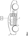
- FIG. 1 illustrates a vehicle with an automated driving system according to one or more embodiments
- FIG. 2 depicts an example scenario of a vehicle traveling according to one or more embodiments
- FIG. 3 depicts an example dataflow of a method for controlling an automated vehicle according to one or more embodiments
- FIG. 4 depicts an example implementation of a time-series analysis for determining operational mode switching according to one or more embodiments.
- FIG. 5 depicts a flowchart of an example method for controlling an automated vehicle according to one or more embodiments.
- module refers to processing circuitry that may include an application specific integrated circuit (ASIC), an electronic circuit, a processor (shared, dedicated, or group) and memory that executes one or more software or firmware programs, a combinational logic circuit, and/or other suitable components that provide the described functionality.
- ASIC application specific integrated circuit
- processor shared, dedicated, or group
- memory that executes one or more software or firmware programs, a combinational logic circuit, and/or other suitable components that provide the described functionality.
- automated or autonomous vehicles include at least some aspects of a safety -critical control function, e.g., steering, throttle, or braking, occur without direct driver input.
- a safety -critical control function e.g., steering, throttle, or braking
- vehicles that provide safety warnings to drivers but do not perform a control function are, in this context, not considered automated, even though the technology necessary to provide that warning involves varying degrees of automation.
- Automated vehicles may use on-board sensors, cameras, global positioning system (GPS), and telecommunications to obtain environment information in order to make judgments regarding safety-critical situations and operate appropriately by effectuating control at some automation level.
- GPS global positioning system
- SAE J3016TM levels and definitions include Level 0—No Automation: The full-time performance by the human driver of all aspects of the dynamic driving task, even when enhanced by warning or intervention systems; Level 1—Driver Assistance: The driving mode-specific execution by a driver assistance system of either steering or acceleration/deceleration using information about the driving environment and with the expectation that the human driver performs all remaining aspects of the dynamic driving task; Level 2—Partial Automation: The driving mode-specific execution by one or more driver assistance systems of both steering and acceleration/deceleration using information about the driving environment and with the expectation that the human driver performs all remaining aspects of the dynamic driving task; Level 3—Conditional Automation: The driving mode-specific performance by an Automated Driving System of all aspects of the dynamic driving task with the expectation that the human driver will respond appropriately to a request to intervene; Level 4—High Automation
- a computing system is used to navigate and/or maneuver the vehicle along a travel route with no input from a human driver.
- the full automation in this mode performs all safety-critical driving functions and monitors roadway conditions for an entire trip and may need only that the driver provide destination or navigation input, but not control at any time during the trip.
- Such full automation includes both occupied and unoccupied autonomous vehicles.
- Level 2/3 automation the vehicle can perform full self-driving functions but needs human intervention in various situations or may request the driver to take control (with some amount of delay allowed in the response).
- Lower Level operational modes facilitate functions like anti-lock brakes, electronic stability control, lane-keeping and the like.
- multiple functions are combined, such as the combination of adaptive cruise control and lane-keeping to make a car that drives itself but needs constant human monitoring and quick intervention; or self-park monitored from outside the vehicle.
- Level 4 automated driving systems has currently been limited to small, geo-fenced areas and low speed operation due to the potential computational complexity involved. Widespread deployment of Level 4 systems is challenged by their inability to function over all operational design domains.
- the technical solutions described herein address such technical challenges of automated driving systems by using driving complexity trend information to enable Level 3 functionality or overcome limitations of Level 4 systems via offloading computational operations used by the Level 4 automation processing.
- vehicles are equipped with sensors that are configured to detect information about the surrounding environment, including the presence of objects in the environment.
- the detected information is sent to a computing system.
- Different operational modes use different types and amounts of computing resources.
- the technical solutions described herein determine computational resources used by the different operational modes. Further, the technical solutions determine amounts of information available, and predict computational resources required to analyze the available information for the different operation modes. Based on the computational resources available and the amount and/or type of information available, the technical solutions described herein facilitate determining the operational mode to be used and switches from the present operation mode to the determined operation mode, if required.
- the technical solutions described herein facilitate an automated vehicle to enable and provide Level 3 functionality by predicting when automated driving functions cannot be available due to the increasing complexity of the environment.
- the automated vehicle can sustain Level 5 functionality by enlisting support from off-board computing systems when the environment becomes too complex for the computing systems equipped in the vehicle to negotiate (“cry for help”).
- the automated vehicle can sustain Level 5 functionality by intelligently allocating computing resources in the computing system equipped in the vehicle or the off-board computing system in difficult environments to focus on region of interest. It should be noted that the technical solutions described herein also facilitate the automated vehicle to switch from and/or to other operational modes than those listed above, which are just few possible examples.
- FIG. 1 schematically illustrates a vehicle 120 with an automated driving system 122 .
- the automated driving system 122 generally includes a sensor system 124 , a control system 126 and a communication system 128 . It should be appreciated that although particular systems are separately defined, each or any of the systems may be otherwise combined or segregated via hardware and/or software.
- the sensor system 124 may include various sensors operable to identify a condition associated with and around the vehicle 120 .
- the sensor system 124 includes a surrounding monitor system that includes but is not limited to sensors such as imagery sensors, RADAR, SONAR, LIDAR and others. It should be appreciated that various sensors may alternatively or additionally be provided.
- the control system 126 generally includes a processor 142 , a memory 144 , and an interface 146 .
- the control system 126 may be a portion of a central vehicle control, a stand-alone unit, or other system such as a cloud-based system.
- the processor 142 may be any type of microprocessor having desired performance characteristics, and the memory 144 may include any type of computer readable medium that stores the data and control algorithms described herein.
- the interface 146 facilitates communication with other systems such as the sensor system 124 , the communication system 128 , and safety-critical control systems such as a braking system 150 , a steering system 160 , and a throttle system 170 to provide selective self -drive control of the vehicle 120 in response to the control algorithms.
- the driver may interact with the control system 126 through a driver vehicle interface (DVI) 180 .
- the DVI 180 may include an instrument panel with a touch screen, keypad, or other interface as well as a steering wheel, pedals, gear shifter, and/or other vehicle control interfaces. It should be appreciated that the vehicle control interfaces for respective safety-critical control systems 150 , 160 , 170 are not illustrated and that various interfaces may be utilized to provide manual and self-drive operations of the vehicle 120 .
- the communication system 128 may be operable to receive information from off-board systems that provide information to the control algorithms to include, but are not limited to, traffic information, weather information, location information and other such information that may facilitate control and navigation of the vehicle 120 .
- the control algorithms are operable to provide selective self-driving control of the vehicle 120 in accord with, for example, a range of vehicle automation that has been classified by agencies such as the National Highway Traffic Safety Administration (NHTSA) and SAE International from Automation Level 0 to Automation Level 5. It should be noted that alternative categorization/naming schemes of the automation levels than those described herein may be used in other embodiments.
- Automation Level 0 No Automation: The driver is in complete and sole control at all times of the primary vehicle controls and is solely responsible for monitoring the roadway and for safe operation.
- the primary vehicle controls are braking, steering, and throttle.
- a vehicle with driver convenience systems that do not have control authority over steering, braking, or throttle would still be considered “Automation Level 0” vehicles.
- Examples of driver convenience systems include forward collision warning, lane departure warning, blind spot monitoring, and systems for automated secondary controls such as wipers, headlights, turn signals, hazard lights, etc.
- Automation Level 1 Full-specific Automation: This Automation Level involves one or more specific control functions. If multiple functions are automated, they operate independently. The driver has overall control, and is solely responsible for safe operation, but can choose to cede limited authority over a primary control such as adaptive cruise control. Automated self-drive systems can provide added control in certain normal driving or crash-imminent situations e.g., dynamic brake support in emergencies. The vehicle may have multiple capabilities that combine individual driver support and crash avoidance technologies, but do not replace driver vigilance and do not assume driving responsibility from the driver. Automation Level 1 may assist or augment the driver, but there is no combination of systems that operate in unison to enable the driver to be disengaged from physically operating the vehicle by having hands off the steering wheel and feet off the pedals at the same time. Examples of function-specific automation systems include: cruise control, automatic braking, and lane keeping.
- Automation Level 2 Combined Function Automation: This Automation Level involves automation of at least two primary control functions designed to work in unison to relieve the driver of control of those functions. Automation Level 2 can utilize shared authority when the driver cedes active primary control in certain limited driving situations. The driver is responsible for monitoring the roadway for safe operation and is expected to be available for control at all times and on short notice. This Automation Level can relinquish control with no advance warning and the driver must be ready to control the vehicle safely.
- An example of combined functions enabling Automation Level 2 is adaptive cruise control in combination with lane centering.
- a major distinction between Automation Level 1 and Automation Level 2 is that, at Automation Level 2 in the specific operating conditions for which the system is designed, the driver is disengaged from physically operating the vehicle with hands off the steering wheel and feet off the pedals at the same time.
- Automation Level 3 Limited Self-Driving Automation: This Automation Level enables the driver to cede full control of all safety-critical functions under certain traffic or environmental conditions and in those conditions to rely heavily on the vehicle to monitor for changes in those conditions that would require transition back to driver control.
- the vehicle is designed to ensure safe operation during the automated driving mode and the driver is expected to be available for occasional control, but with a sufficiently comfortable transition time.
- An example is an automated vehicle that can determine when the system is no longer able to support automation, such as from an oncoming construction area, and then signal to the driver to reengage in the driving task.
- Automation Level 2 and Automation Level 3 is that at Automation Level 3, the driver is not expected to constantly monitor the roadway.
- Level 4 High Automation: The driving mode-specific performance by an Automated Driving System of all aspects of the dynamic driving task, even if a human driver does not respond appropriately to a request to intervene.
- Automation Level 5 Full Self-Driving Automation: This Automation Level performs all safety-critical driving functions and monitors roadway conditions for an entire trip. Such a design anticipates that the driver provides destination or navigation input, but is not expected to be available for control at any time during the trip. Automation Level 5 permits occupied and unoccupied vehicles as safe operation rests solely on the automated vehicle system.
- Level 3 is used to represent partial automation levels such as Levels 1-3
- Level 4 is used to represent high automation levels such as Levels 4-5.
- the technical solutions described herein support Automation Level 3 systems by indicating when driver input will be required based on increased driving complexity and Automation Level 4 systems by indicating when utilization of elastic computing resources will be required to maintain Level 4 operation.
- the operational mode and driving complexity trend information is used to anticipate required takeover operations (Level 3 functionality) or to overcome limitations of the onboard computing system via offloading computation to an off-board computer system 190 or via reallocation of onboard computing resources.
- the off-board computer system 190 can be a computer server, or any other computing system that is separate from the control system 126 that is ‘on-board’ the vehicle 120 .
- the off-board computer system 190 can be more powerful compared to the control system 126 , for example, have a faster processor, have more memory, have additional computing resources such as a graphical programming unit (GPU), an artificial neural network (ANN) chip, and the like.
- GPU graphical programming unit
- ANN artificial neural network
- FIG. 2 depicts an example scenario of a vehicle traveling according to one or more embodiments.
- the automated vehicle 120 is traveling along a route 200 , which may be divided into one or more path segments or regions.
- the vehicle 120 is presently in a region 210 of the route 200 .
- the control system 126 based on the current vehicle kinematics (speed, acceleration etc.) can predict a region 220 for the vehicle 120 at a future time, say t 2 .
- the predicted region 220 can be approaching after a predetermined time interval t 2 , such as 2 minutes, 1 minute, 15 minutes, and the like.
- the time interval t 2 is adjustable.
- route 200 and the regions 210 and 220 are depicted with ‘straight’ lines, the route and/or regions may include curved road segments, turns, intersections, parking lots, highway exit ramps, highway entry ramps, off-road (dirt) segment, high occupancy vehicle (HOV) lane, or any other specific type of route element.
- route and/or regions may include curved road segments, turns, intersections, parking lots, highway exit ramps, highway entry ramps, off-road (dirt) segment, high occupancy vehicle (HOV) lane, or any other specific type of route element.
- the control system 126 tracks a complexity of the environmental information of the region 220 that the vehicle 20 is approaching. Based on the complexity, the control system 126 monitors and determines an operational mode to use for automated driving system in the upcoming region 220 . For example, the control system 126 , based on the complexity determines whether to continue using a present automation level, such as Level 3, or to issue a takeover request to the driver. Alternatively, or in addition, the control system can determine whether to continue operating in a Level 4 automation by employing elastic computing approaches. For example, the control system 126 tracks static objects (bridges, signs, etc.), dynamic objects (vehicles, pedestrians, etc.), and objects near acceptance filter (indication of scene complexity) in the region 220 . Further, the control system 126 characterizes the environment (e.g., lighting, weather, map, GPS quality, wireless quality) in the region 220 . The control system 126 computes the complexity of the information for the approaching region 220 from the object data and environment measures.
- a present automation level such
- the control system 126 adjusts/calibrates the complexity metric based on backend parameters from crowd-sourcing aggregation from other vehicles that are in the region 220 or that have passed through the region 220 within a predetermined interval. Further, the control system 126 tracks the computed complexity metric for the region 220 as a time series and predicts when the complexity metric can exceed the ability of the vehicle 120 to operate in autonomous mode. If the forward region 220 becomes too complex, for example if the complexity metric exceeds a predetermined threshold that the vehicle 120 can process in real time for providing automated driving functions, the control system 126 performs mitigation measures or requests takeover based on the increasing trend of the complexity metric.
- FIG. 3 depicts an example dataflow of a method for driving complexity characterization and controlling an automated vehicle according to one or more embodiments.
- the control system 126 executes the method.
- the control system 126 receives sensor data from the one or more sensors of the vehicle 120 and computes a first complexity metrics based on the sensor data, at 310 .
- the first complexity metrics based on the sensor data is computed as:
- ISCM number ⁇ ⁇ of ⁇ ⁇ detections ⁇ ⁇ within ⁇ ⁇ predetermined threshold total ⁇ ⁇ number ⁇ ⁇ of ⁇ ⁇ detections
- ISCM is an individual sensor's complexity metric, which is a first complexity metric computed based on sensor data from the multiple (N) sensors 124 of the vehicle 120 .
- Each detection by a sensor has a corresponding confidence score, and a confidence score above a predetermined threshold indicates if the detection is within a confidence level to take action based on the detection.
- the first complexity metric for a sensor “S” accordingly computes a ratio of a number of detections by the sensor “S” that have at least the predetermined threshold level of confidence score and the total number of detections by the sensor “S”.
- the ISCM is computed separately for each sensor from the sensors 124 .
- ISCM 1 is computed for a first sensor (e.g.: front radar)
- ISCM 2 is computed for a second sensor (e.g. front LIDAR)
- ISCM 3 is computed for a third sensor (e.g. front camera)
- ISCM i is computed for an i th sensor (e.g. side radar), and so on for each sensor in the vehicle 120 .
- the confidence score threshold value for each sensor can be different, which is a predetermined value for the computation, and which can be adjustable.
- the control system 126 performs sensor fusion to combine the input received from the sensors 124 and further compute complexity metrics based on the sensor fusion data, at 320 .
- Sensor fusion combines the sensory data or data derived from the disparate sources such that the resulting information has less uncertainty than would be possible when these sources were used individually.
- the sensor fusion is performed on the sensory data from sensors with overlapping fields of view.
- the sensor fusion complexity metric is computed as:
- SFCM number ⁇ ⁇ of ⁇ ⁇ fused ⁇ ⁇ objects total ⁇ ⁇ number ⁇ ⁇ of ⁇ ⁇ objects
- SFCM is the sensor fusion complexity metric based on the sensor fusion results and objects detected without the sensor fusion.
- the SFCM is computed as a ratio of the number of objects detected as a result of the sensor fusion (which eliminates duplicate objects) and the total number of objects detected by the sensors 124 .
- the control system 126 performs object tracking and computes an object tracking complexity metric, at 330 .
- the object tracking includes determining the number of stably tracked objects from the total number detected by the sensors 124 . For example, the object tracking continuously monitors if a detected object exists in at least a predetermined proportion of frames in a set of successive frames that are sensed by the sensors 124 . For example, consider an example scenario where an object is detected in a frame-1. The object detection is assigned an initial stability score. If the same object is detected in one or more additional frames that are further sensed by the sensors 124 , the stability score of the object may be incremented or maintained. If the object is not sensed in the successive frames, the stability score is reduced.
- the stability score of the object is above a predetermined threshold, the confidence of the object detection is considered high enough to make a decision regarding maneuvering the vehicle 120 based on the object.
- An object that has a stability score above the predetermined threshold is considered a ‘stably detected’ object.
- the object tracking complexity metric is computed as:
- OTCM number ⁇ ⁇ of ⁇ ⁇ stably ⁇ ⁇ tracked ⁇ ⁇ objects total ⁇ ⁇ number ⁇ ⁇ of ⁇ ⁇ tracked ⁇ ⁇ objects
- a number of stably tracked objects is the number of objects with stability score above the predetermined threshold in a predetermined number of recent frames.
- the total number of tracked objects is the number of objects that have been tracked in the same frames.
- the number of frames to use for the analysis is an adjustable parameter and a predetermined value at the time of computation. In one or more examples, the number of frames may be based on a predetermined interval for which the sensor data is received and analyzed.
- the control system 126 receives environmental data for the region 220 FIG. 2 , at 340 .
- the environmental conditions include, but are not limited to, lighting conditions (dark, bright etc.), weather conditions (rainy, snowy, dry etc.), road surface condition (slippery, construction in progress etc.), traffic conditions (light traffic, high traffic etc.), and other such environmental factors.
- the environmental factors are received from one or more sources.
- the lighting conditions are determined using light sensors included in the sensors 124 of the vehicle 120 .
- the rainy/dry conditions can be determined using humidity sensors and/or state of automatic wipers equipped in the vehicle 120 .
- the road surface conditions are determined using sensors 124 such as camera/suspension sensors and the like. In the above examples using the sensors 124 , the control system 126 predicts the conditions in the region 220 based on the sensor data from the sensors 124 at the present region 210 .
- control system 126 receives the conditions from other sources, such as designated computer servers monitoring and providing such data for the region 220 .
- the weather conditions may be received from a first source, such as a weather computer server 342
- the traffic conditions are received from a traffic computer server 344 .
- Other such data sources may be included for the other types of data received. It should be appreciated that the above list is a few examples and that, in other embodiments, different environmental data may be received from different sources than those listed above.
- the environmental data further includes quantitative attributes of the communication network available in the region 220 .
- the quantitative attributes include, but not limited to, signal strength, network type (e.g. 4G, 3G etc.), level of service, and the like.
- the environmental data further includes age of the available information from the region, such as the timestamp of the last reported traffic/road related incident in the region 220 received via the communication network.
- the environmental data includes quantitative attributes about the GPS network in the region 220 .
- quantitative attributes For example, signal to noise ratio, number of GPS satellites, receiver type (e.g. L1/L5), dilution of precision measures, and the like.
- the environmental data further includes quantitative attributes about the map of the region 220 .
- the map attributes include curvature of road in the map, number of lanes, number of intersections, complexity of the intersections (predetermined values associated with the intersections based on number of lanes, number of traffic incidents empirically reported at the intersection, etc.), number of attributes associated with the region (e.g. X curves+Y intersections), and the like.
- the control system 126 further receives complexity information from other vehicles 120 ′, at 350 .
- the other vehicles 120 ′ are selected based on the other vehicles 120 ′ traveling through the region 220 within a predetermined interval.
- the control system 126 receives the complexity information from the other vehicles 120 ′ via the communication system 128 .
- the control system 126 determines a scene complexity metric based on the one or more complexity metrics received/computed and the one or more quantitative attributes received/computed, at 360 .
- r is a complexity level indicating automated drivability of the vehicle 120 in the region 220 that is computed based on each property p i , which represents each of the complexity metrics and attributes computed/received (e.g., ISCM, SFCM, OTCM, environment metrics).
- Each property p i is computed as a function of the corresponding parameters of interest (e.g. radar/camera/lidar, ambient light, etc.).
- each property is associated with a weighting value w i that is used during computation of the complexity level r.
- the weight values are predetermined values at the time of computation. In one or more examples, the weight values are adjustable. Further yet, in one or more examples, the weight values are dynamically computed by the control system 126 , for example, using machine learning based on historic data.
- a machine learning technique such as long short term memory (LSTM) can be used over a time-series of raw or processed sensor data to automatically predict the complexity level r.
- LSTM is one example of time-series analysis that can be used to determine the driving complexity result, and that in other embodiments any other state based learning algorithm can be used for the analysis.
- the analysis determines the driving complexity level at the present time t based on earlier instances in the predetermined interval being analyzed.
- the machine learning techniques such as the LSTM, automatically and dynamically predicts the complexity level without a fixed equation and weighting factors as in case of the equations above.
- the machine learning also uses the ISCM, SFCM, and other properties as the input and then automatically learns to use these properties to predict the complexity level r based on a dynamically learned set of weights.
- the raw sensor data is directly sent into the machine learning algorithm (e.g.: LSTM), which can directly predict, from the raw sensor data, the complexity level r (without specifying IS CM, SFCM or other properties and weights).
- the complexity level r can then be compared with a predetermined threshold to determine drivability.
- the machine learning output is the drivability resulting from such a comparison.
- FIG. 4 depicts an example implementation of the LSTM for determining driving complexity according to one or more embodiments.
- LSTM blocks are stacked together, with each LSTM block 405 forwarding its output to a next LSTM block 405 .
- LSTM blocks are depicted, in other examples a different numbers of LSTM blocks can be used.
- raw or processed sensor data are input as a time-series 410 X(t) at the present time t.
- the LSTM block receives as input h(t ⁇ 1), which is the output from the previous LSTM unit 405 and C(t ⁇ 1), which is the “memory” of the previous LSTM unit 405 .
- Each single LSTM block 405 predicts the complexity level r by considering the current input (X(t)), previous output (h(t ⁇ 1)) and previous memory (C(t ⁇ 1)).
- the LSTM block 405 generates a new output (h(t)) and alters its own memory (C(t)).
- the sensor data X(t) at time t includes the raw data directly obtained from the sensors 124 , for example, pixels from imagery sensors, point cloud from Lidar or radar sensors, the temperature information from temperature sensors, etc..
- the sensor data includes processed raw sensor data, for example, the detection objects information and the tracking information from image sensors, Lidar sensors, or radar sensors.
- the input includes the attributes described herein, such as the properties used in the weighted summation method.
- the output h(t) at time t is the predicted complexity level r.
- the LSTM (or any other time series) analysis facilitates the system to automatically learn when a complex situation is encountered and generate a robust detection by considering both spatial and temporal information. For example, as the vehicle 120 is moving through different regions, the time series analysis indicates that the complexity of the regions is increasing over a period of time and may predict a high complexity level r as the output.
- the complexity level is computed either using m different properties or through certain machine learning methods such as LSTM to which the control system 126 has access.
- the properties used by the control system 126 can be adjustable.
- the control system 126 uses the sensor data and the sensor fusion only.
- the control system 126 uses the environmental data from other vehicles 120 ′ and the external data sources such as computer servers.
- the value of m can be different in different examples.
- the complexity level r is used to determine if computational resources are available to analyze the available information to provide automated driving at Level 3/4 for the vehicle 120 , at 370 FIG. 3 .
- the complexity level r is compared with predetermined threshold value, and if r >threshold, the control system 126 seeks remediation measures (Level 4), issues an alert for the driver (Level 3), or requests a takeover by the driver (Level 3) as the vehicle 120 drives through the region 220 , as shown at 380 .
- the control system 126 if the complexity level r is smaller than the predetermined threshold, the control system 126 continues to provide the automated driving assistance through the region 220 . In one or more examples, the control system 126 compares the complexity level r with another threshold value to check if the computing system equipped in the vehicle 120 can provide the automated driving assistance by itself, at 390 . If the computing system does not have the resources to perform the analysis for the automated driving assistance, the control system 126 seeks the assistance of the external computing system 190 via the communication system 128 , at 390 . The control system 126 allocates the computational resources for the automated driving assistance, for example between the computation resources available in the vehicle 120 and the external computing system 190 . If the computing system of the vehicle 120 has the computational resources to analyze the available information, the automated driving assistance is determined by the computing system itself. The automated driving assistance is then executed, at 395 .
- Executing the automated driving assistance includes performing one or more maneuvers for the vehicle by sending corresponding commands to the one or more actuators of the vehicle to adjust the vehicle kinematics (e.g. speed, acceleration, steering angle etc.).
- vehicle kinematics e.g. speed, acceleration, steering angle etc.
- the thresholding is used to determine whether to issue a takeover request (Level 3) or employ elastic computing resources (Level 4), or to continue with the automated driving assistance based on the complexity level r.
- the LSTM may directly output the decision results as h(t) without explicitly outputting the complexity level r and a threshold depending on different implementation preference.
- FIG. 5 depicts a flowchart of an example method for determining automated driving complexity and controlling an automated vehicle according to one or more embodiments.
- the method includes perceiving a near field environment for the vehicle 120 , at 510 .
- the near field environment includes the environmental data for the region 210 in which the vehicle 120 is presently traveling.
- the environmental data for the near field can be obtained from one or more sources, such as the sensors 124 from the region that is within a line of sight of the sensors 124 .
- the method further includes perceiving a long range environment, at 520 .
- the long range environment is perceived by obtaining environmental data for a region that is out of range of the sensors 124 of the vehicle 120 .
- the environmental data for the long range region, for example region 220 is obtained using the communication system 128 via one or more external data sources such as other vehicles, data service providers, and so on. Further, in one or more examples, the environmental data for the region 220 is obtained by predicting the environmental factors in that region using time series analysis and/or using empirical data.
- the method includes analyzing the received data for performing object detection and maintaining an object list and computing environment metrics based on the object detection for the region 210 and the region 220 , at 530 .
- the object detection includes determining static objects (stationary e.g. road signs, buildings) and dynamic objects (moving e.g. other vehicles, pedestrians) in the region being analyzed.
- the object detection and analysis can be performed using known object detection techniques for different types of sensor data and/or using sensor fusion techniques by combining the sensor data obtained from the multiple sensors 124 .
- the method further includes computing the complexity level r for the region 220 , at 540 .
- the complexity level computation includes computing one or more different complexity metrics, which include the complexity (ISCM) based on each of the different sensors 124 , the complexity (SFCM) based on sensor fusion detection, the complexity based on object tracking across multiple frames (OTCM), and the like.
- Each of these complexities represents a property (pi) as described in the calculations described earlier.
- the environmental data obtained from one or more sources such as the traffic conditions, weather conditions, network conditions, road surface conditions, and the like are used to compute the confidence level r as described above.
- the environmental factors also represent the different properties (pi).
- the weight values assigned to each property is accessed and used for the computations.
- a complexity level r can be predicted based on a time series analysis such as the LSTM.
- the method further includes predicting if the complexity level r is above a complexity threshold that the control system 126 of the vehicle 120 can handle for providing automated driving assistance, at 550 .
- the complexity level r is compared with a predetermined complexity threshold value(s).
- the decision can be predicted directly from the LSTM without outputting the complexity level r and comparing with the predetermined complexity threshold value(s) explicitly.
- the control system 126 determines that the complexity level is manageable for the control system 126 in the current allocation of computational resources itself, i.e. r ⁇ low-complexity threshold, the control system 126 continues to analyze the environmental data for the region 220 and provide automated driving assistance for the vehicle when traveling through the region 220 , at 565 . Analyzing the environmental data and providing the automated driving assistance includes generating a trajectory for the vehicle 120 through the region 220 . The method is continuously executed by the control system 126 . Executing the trajectory includes maneuvering the vehicle 120 according to the trajectory.
- control system 126 determines that the complexity level is higher than what can be analyzed by the current configuration of the computational resources, the control system 126 further analyzes the complexity level to check if a trajectory can be determined by reallocating the computational resources within the computing system of the vehicle 120 or if the analysis is unmanageable by the computing system. For example, the control system 126 checks if the complexity level is such that low-complexity threshold ⁇ r ⁇ high-complexity threshold.
- the control system 126 can offload at least a subset of the automated driving tasks to an additional computing system, at 552 . Offloading the tasks may include assigning computational resources from the external computing system 190 to perform the subset of tasks to complete the analysis of the environmental data to determine the trajectory of the vehicle 120 in the region 220 .
- the external computing system 190 upon receiving the request to provide the automated driving assistance by generating the trajectory for the vehicle 120 , indicates if a navigable path can be generated by the external computing system 190 , at 560 .
- the external computing system 190 may also not be able to generate a safe trajectory for the vehicle 120 prior to the vehicle 120 reaching the region 220 .
- the external computing system 190 indicates to the control system 126 that a navigable path, or trajectory cannot be generated, at 570 .
- the control system 126 provides an alert to the driver, at 580 or invokes remediation measures (i.e., performs a minimal risk condition maneuver that slows/stops the vehicle and pulls to the side of the road).
- the alert indicates to the driver that manual takeover is required.
- the alert also indicates a time interval, such as 5 seconds, 10 seconds, or the like in which the driver control must be taken.
- the alert may be provided in one or more ways.
- the alert may be provided via the DVI 180 .
- the alert may be provided as haptic feedback via the steering.
- the alert may be provided as audio feedback via speakers installed in the vehicle 120 . Additional and/or alternative forms of alert may be provided in other embodiments, such as via a mobile device of the driver that is registered with the control system 126 .
- Level 3 operation After the indicated time interval, the driver has to take control of at least a subset of tasks for maneuvering the vehicle 120 , such as the steering and the acceleration.
- Level 4 operation the control system 126 executes in the minimal risk condition, until the driver initiates a switch to re-engage the fully automated operational mode (Level 4).
- the control system 126 Upon switching to the fully automated mode, the control system 126 continues to execute the method described herein to monitor the automated driving complexity of the vehicle 120 .
- the external computing system 190 can generate the trajectory, the external computing system 190 indicates as such, at 560 , and generates and sends the trajectory to the control system 126 via the communication system 128 , at 565 .
- the received trajectory is then executed by the vehicle 120 for the region 220 , at 565 .
- the method is continuously executed by the control system 126 . Executing the trajectory includes maneuvering the vehicle 120 according to the trajectory.
- the control system 126 determines that the complexity of the region 220 is low, the control system 126 performs a reallocation of the computational resources of the computing system of the vehicle 120 to facilitate generating a trajectory for the region 220 , at 554 .
- the reallocation of the computation resources can include changing loop times for analyzing sensory data.
- the loop times for analyzing sensor data from sensors facing a particular side of the vehicle 120 e.g. rear, or right side, is reduced.
- algorithm used for analyzing sensors facing a particular side of the vehicle 120 is changed to an algorithm that uses lesser computational resources. It should be noted that any other adjustments of the computational resources can be performed in other embodiments.
- the technical solutions described herein thus facilitate driving complexity determination system for an automated vehicle.
- the technical solutions described herein further facilitate the control system of the vehicle to attempt to continue operating in the fully-automated operational mode when the complexity of the upcoming region is manageable for the present configuration of the computing system of the vehicle. Further, the technical solutions determine if a different configuration of the computing system, with computational resources reallocated can manage generating and executing a trajectory in the fully-automated operational mode for the upcoming region. Further yet, if the computing system of the vehicle is unable to generate the trajectory, the technical solutions described herein also facilitate checking if an external computing system can be used to generate the trajectory for the vehicle to travel through the upcoming region.
- the technical solutions described herein facilitate the vehicle to request driver intervention or execute a minimal risk condition maneuver. Further yet, the technical solutions described herein facilitate alerting the driver to take over the control of the vehicle at least a predetermined time interval prior to reaching a region with a predicted complexity level in which a trajectory cannot be generated by the automated vehicle.
- the technical solutions described herein facilitate measuring complexity of the environment of an upcoming region of an automated vehicle based on static objects (i.e., clutter) and dynamic elements (moving objects, environmental conditions: time of day, year, etc.).
- the technical solutions can further provide indication of complex environment of the upcoming region and allow sufficient time to bring driver back in the loop to take over control of the vehicle (Level 3) or offloads/reallocates system tasks to continue operating in the fully -automated operational mode (Level 4).
- the technical solutions employ direct sensing & communications to track increasing complexity of the environment. Further yet, the technical solutions facilitate providing system confidence information to the ADAS or to the driver via the DVI.
- the technical solutions described herein thus improve the safety of operation of an automated driving system. Further yet, the technical solutions described herein facilitate an improvement of a computing system that the system uses to control the vehicle. Further yet, the technical solutions described herein facilitate the control system to generate and provide commands that cause the vehicle kinematics to be adjusted such as, causing the vehicle to move at a particular speed, accelerate at a particular rate, steer in a particular direction, etc. The technical solutions described herein adjust the vehicle kinematics by generating and sending commands to one or more actuators/motors in the vehicle.
- threshold values are few possible examples, and that in other embodiments, different and or fewer/additional threshold values may be used. Further, the types of alerts described are examples, and that in other embodiments, different alerts may be generated. In one or more examples, the threshold values and the alert types may be configurable by a user of the vehicle 120 .
- the present technical solutions may be a system, a method, and/or a computer program product at any possible technical detail level of integration
- the computer program product may include a computer readable storage medium (or media) having computer readable program instructions thereon for causing a processor to carry out aspects of the present technical solutions.
- the computer readable storage medium can be a tangible device that can retain and store instructions for use by an instruction execution device.
- the computer readable storage medium may be, for example, but is not limited to, an electronic storage device, a magnetic storage device, an optical storage device, an electromagnetic storage device, a semiconductor storage device, or any suitable combination of the foregoing.
- a non-exhaustive list of more specific examples of the computer readable storage medium includes the following: a portable computer diskette, a hard disk, a random access memory (RAM), a read-only memory (ROM), an erasable programmable read-only memory (EPROM or Flash memory), a static random access memory (SRAM), a portable compact disc read-only memory (CD-ROM), a digital versatile disk (DVD), a memory stick, and the like, and any suitable combination of the foregoing.
- RAM random access memory
- ROM read-only memory
- EPROM or Flash memory erasable programmable read-only memory
- SRAM static random access memory
- CD-ROM compact disc read-only memory
- DVD digital versatile disk
- memory stick and the like, and any suitable combination of the foregoing.
- a computer readable storage medium is not to be construed as being transitory signals per se, such as radio waves or other freely propagating electromagnetic waves, electromagnetic waves propagating through a waveguide or other transmission media (e.g., light pulses passing through a fiber-optic cable), or electrical signals transmitted through a wire.
- Computer readable program instructions described herein can be downloaded to respective computing/processing devices from a computer readable storage medium or to an external computer or external storage device via a network, for example, the Internet, a local area network, a wide area network and/or a wireless network.
- the network may comprise copper transmission cables, optical transmission fibers, wireless transmission, routers, firewalls, switches, gateway computers and/or edge servers.
- a network adapter card or network interface in each computing/processing device receives computer readable program instructions from the network and forwards the computer readable program instructions for storage in a computer readable storage medium within the respective computing/processing device.
- Computer readable program instructions for carrying out operations of the present technical solutions may be assembler instructions, instruction-set-architecture (ISA) instructions, machine instructions, machine dependent instructions, microcode, firmware instructions, state-setting data, configuration data for integrated circuitry, or either source code or object code written in any combination of one or more programming languages, including an object oriented programming language such as Smalltalk, C++, or the like, and procedural programming languages, such as the “C” programming language or similar programming languages.
- the computer readable program instructions may execute entirely on the user's computer, partly on the user's computer, as a stand-alone software package, partly on the user's computer and partly on a remote computer or entirely on the remote computer or server.
- the remote computer may be connected to the user's computer through any type of network, including a local area network (LAN) or a wide area network (WAN), or the connection may be made to an external computer (for example, through the Internet using an Internet Service Provider).
- electronic circuitry including, for example, programmable logic circuitry, field-programmable gate arrays (FPGA), or programmable logic arrays (PLA) may execute the computer readable program instructions by utilizing state information of the computer readable program instructions to personalize the electronic circuitry, in order to perform aspects of the present technical solutions.
- These computer readable program instructions may be provided to a processor of a general purpose computer, special purpose computer, or other programmable data processing apparatus to produce a machine, such that the instructions, which execute via the processor of the computer or other programmable data processing apparatus, create means for implementing the functions/acts specified in the flowchart and/or block diagram block or blocks.
- These computer readable program instructions may also be stored in a computer readable storage medium that can direct a computer, a programmable data processing apparatus, and/or other devices to function in a particular manner, such that the computer readable storage medium having instructions stored therein comprises an article of manufacture including instructions which implement aspects of the function/act specified in the flowchart and/or block diagram block or blocks.
- the computer readable program instructions may also be loaded onto a computer, other programmable data processing apparatus, or other device to cause a series of operational steps to be performed on the computer, other programmable apparatus or other device to produce a computer implemented process, such that the instructions which execute on the computer, other programmable apparatus, or other device implement the functions/acts specified in the flowchart and/or block diagram block or blocks.
- each block in the flowchart or block diagrams may represent a module, segment, or portion of instructions, which comprises one or more executable instructions for implementing the specified logical function(s).
- the functions noted in the blocks may occur out of the order noted in the Figures.
- two blocks shown in succession may, in fact, be executed substantially concurrently, or the blocks may sometimes be executed in the reverse order, depending upon the functionality involved.
- a second action may be said to be “in response to” a first action independent of whether the second action results directly or indirectly from the first action.
- the second action may occur at a substantially later time than the first action and still be in response to the first action.
- the second action may be said to be in response to the first action even if intervening actions take place between the first action and the second action, and even if one or more of the intervening actions directly cause the second action to be performed.
- a second action may be in response to a first action if the first action sets a flag and a third action later initiates the second action whenever the flag is set.
- the phrases “at least one of ⁇ A>, ⁇ B>, . . . and ⁇ N>” or “at least one of ⁇ A>, ⁇ B>, ⁇ N>, or combinations thereof” or “ ⁇ A>, ⁇ B>, . . . and/or ⁇ N>” are to be construed in the broadest sense, superseding any other implied definitions hereinbefore or hereinafter unless expressly asserted to the contrary, to mean one or more elements selected from the group comprising A, B, . . . and N.
- the phrases mean any combination of one or more of the elements A, B, . . . or N including any one element alone or the one element in combination with one or more of the other elements which may also include, in combination, additional elements not listed.
- any module, unit, component, server, computer, terminal or device exemplified herein that executes instructions may include or otherwise have access to computer readable media such as storage media, computer storage media, or data storage devices (removable and/or non-removable) such as, for example, magnetic disks, optical disks, or tape.
- Computer storage media may include volatile and non-volatile, removable and non-removable media implemented in any method or technology for storage of information, such as computer readable instructions, data structures, program modules, or other data. Such computer storage media may be part of the device or accessible or connectable thereto. Any application or module herein described may be implemented using computer readable/executable instructions that may be stored or otherwise held by such computer readable media.
Abstract
Description
p i =f(x 1 , x 2 , . . . , x i);
r=Σi=1 mwipi
f t=σ(W f[h −1 ,x t]+b f)
i t=σ(W i[h t−1 , x t]+b f)
{tilde over (c)} t=tanh(W c[h t−1 , x t]+b c)
o t=σ(W o[h t−1 , x t]+b o)
c t =f t +C t−1 +t i *{tilde over (c)} t
h t=ot*tanh(c t)
Claims (18)
Priority Applications (3)
| Application Number | Priority Date | Filing Date | Title |
|---|---|---|---|
| US15/886,492 US10745006B2 (en) | 2018-02-01 | 2018-02-01 | Managing automated driving complexity of the forward path using perception system measures |
| CN201910073765.0A CN110103984B (en) | 2018-02-01 | 2019-01-25 | Managing autopilot complexity for a forward path using a perception system measure |
| DE102019102173.1A DE102019102173A1 (en) | 2018-02-01 | 2019-01-29 | ADMINISTRATION OF THE AUTOMATED DRIVING COMPLEXITY OF THE FOREGOING ROUTE USING THE PERCEPTION SYSTEM |
Applications Claiming Priority (1)
| Application Number | Priority Date | Filing Date | Title |
|---|---|---|---|
| US15/886,492 US10745006B2 (en) | 2018-02-01 | 2018-02-01 | Managing automated driving complexity of the forward path using perception system measures |
Publications (2)
| Publication Number | Publication Date |
|---|---|
| US20190232955A1 US20190232955A1 (en) | 2019-08-01 |
| US10745006B2 true US10745006B2 (en) | 2020-08-18 |
Family
ID=67224506
Family Applications (1)
| Application Number | Title | Priority Date | Filing Date |
|---|---|---|---|
| US15/886,492 Active 2038-08-18 US10745006B2 (en) | 2018-02-01 | 2018-02-01 | Managing automated driving complexity of the forward path using perception system measures |
Country Status (3)
| Country | Link |
|---|---|
| US (1) | US10745006B2 (en) |
| CN (1) | CN110103984B (en) |
| DE (1) | DE102019102173A1 (en) |
Cited By (4)
| Publication number | Priority date | Publication date | Assignee | Title |
|---|---|---|---|---|
| US20210221401A1 (en) * | 2020-01-20 | 2021-07-22 | Honda Motor Co., Ltd. | Control system, control method, vehicle, and computer-readable storage medium |
| US11299172B2 (en) * | 2018-03-06 | 2022-04-12 | C.R.F. Societa' Consortile Per Azioni | Automotive autonomous driving to perform complex recurrent low speed manoeuvres |
| US11393184B2 (en) | 2020-11-13 | 2022-07-19 | Denso International America, Inc. | Systems and methods for adaptive bounding box selection |
| US11453417B2 (en) | 2020-12-03 | 2022-09-27 | GM Global Technology Operations LLC | Automated driving control systems and methods based on intersection complexity |
Families Citing this family (29)
| Publication number | Priority date | Publication date | Assignee | Title |
|---|---|---|---|---|
| SG10201805030YA (en) * | 2018-06-12 | 2020-01-30 | Nec Asia Pacific Pte Ltd | A system and method for deduplicating person detection alerts |
| US10760918B2 (en) | 2018-06-13 | 2020-09-01 | Here Global B.V. | Spatiotemporal lane maneuver delay for road navigation |
| DE102018219376A1 (en) * | 2018-11-13 | 2020-05-14 | Robert Bosch Gmbh | Procedures for selecting and accelerating action responses |
| KR102555916B1 (en) * | 2018-12-12 | 2023-07-17 | 현대자동차주식회사 | Apparatus and method for identificating odm data reliability and vehicle including the same |
| CN115567891A (en) * | 2019-06-05 | 2023-01-03 | 华为技术有限公司 | Automatic driving information indicating method, automatic driving information acquiring method, automatic driving information sending method and device |
| US11458967B2 (en) * | 2019-07-10 | 2022-10-04 | Ford Global Technologies, Llc | Lane-centering assistance |
| FR3101311B1 (en) * | 2019-09-26 | 2021-09-10 | Psa Automobiles Sa | Method and system for managing the deactivation of an autonomous driving functionality provided by a driving assistance system of a motor vehicle in the vicinity of a road intersection |
| EP3809226B1 (en) * | 2019-10-15 | 2023-09-06 | Zenuity AB | Method and system for development and verification of autonomous driving features |
| DE102019128115A1 (en) * | 2019-10-17 | 2021-04-22 | Bayerische Motoren Werke Aktiengesellschaft | Vehicle model for longitudinal dynamics |
| US11567495B2 (en) | 2019-12-11 | 2023-01-31 | Toyota Motor Engineering & Manufacturing North America, Inc. | Methods and systems for selecting machine learning models to predict distributed computing resources |
| CN112257486B (en) * | 2019-12-23 | 2023-12-29 | 北京国家新能源汽车技术创新中心有限公司 | Computing force distribution method, computing force distribution device, computer equipment and storage medium |
| US11385656B2 (en) * | 2020-01-22 | 2022-07-12 | Huawei Technologies Co., Ltd. | System, device and method of identifying and updating the operational design domain of an autonomous vehicle |
| CN112740295B (en) * | 2020-03-31 | 2022-05-10 | 华为技术有限公司 | Method and device for detecting complexity of vehicle driving scene |
| DE102020204353A1 (en) * | 2020-04-03 | 2021-10-07 | Robert Bosch Gesellschaft mit beschränkter Haftung | Method and device for operating a motor vehicle in an automated driving mode |
| DE102020109761A1 (en) * | 2020-04-08 | 2021-10-14 | Valeo Schalter Und Sensoren Gmbh | Environment sensor system |
| JP7322804B2 (en) * | 2020-05-13 | 2023-08-08 | トヨタ自動車株式会社 | Dispatch device and vehicle |
| US11433920B2 (en) | 2020-05-29 | 2022-09-06 | Robert Bosch Gmbh | Map-based prediction and mitigation of performance limitations for autonomous vehicles |
| US11312393B2 (en) | 2020-05-29 | 2022-04-26 | Robert Bosch Gmbh | Artificially falsifying sensor data to initiate a safety action for an autonomous vehicle |
| CN112069888B (en) * | 2020-07-31 | 2024-03-22 | 深圳市金溢科技股份有限公司 | Vehicle checking method and system, road side equipment, vehicle-mounted equipment and handheld terminal |
| US11713979B2 (en) | 2020-08-27 | 2023-08-01 | Here Global B.V. | Method, apparatus, and computer program product for generating a transition variability index related to autonomous driving |
| US11691643B2 (en) | 2020-08-27 | 2023-07-04 | Here Global B.V. | Method and apparatus to improve interaction models and user experience for autonomous driving in transition regions |
| US11687094B2 (en) | 2020-08-27 | 2023-06-27 | Here Global B.V. | Method, apparatus, and computer program product for organizing autonomous vehicles in an autonomous transition region |
| CN112277951B (en) * | 2020-10-29 | 2021-08-20 | 北京罗克维尔斯科技有限公司 | Vehicle perception model generation method, vehicle automatic driving control method and device |
| CN112541408B (en) * | 2020-11-30 | 2022-02-25 | 北京深睿博联科技有限责任公司 | Feasible region identification method, device, equipment and computer readable storage medium |
| US20220185331A1 (en) * | 2020-12-11 | 2022-06-16 | Zoox, Inc. | Calibration based on semantic objects |
| JP7256168B2 (en) * | 2020-12-28 | 2023-04-11 | 本田技研工業株式会社 | VEHICLE CONTROL DEVICE, VEHICLE CONTROL METHOD, AND PROGRAM |
| US11854264B2 (en) * | 2021-06-18 | 2023-12-26 | Kyndryl, Inc. | Speculative actions based on predicting negative circumstances |
| US20230194704A1 (en) * | 2021-12-22 | 2023-06-22 | Gm Cruise Holdings Llc | Anomaly prioritization using dual-mode adaptive radar |
| US20240071151A1 (en) | 2022-08-23 | 2024-02-29 | Steering Solutions Ip Holding Corporation | Adaptive controller performance analyzer and algorithm optimizer |
Citations (24)
| Publication number | Priority date | Publication date | Assignee | Title |
|---|---|---|---|---|
| US20110190972A1 (en) * | 2010-02-02 | 2011-08-04 | Gm Global Technology Operations, Inc. | Grid unlock |
| US8352112B2 (en) * | 2009-04-06 | 2013-01-08 | GM Global Technology Operations LLC | Autonomous vehicle management |
| US20130041548A1 (en) * | 2010-02-04 | 2013-02-14 | Wolfgang Krautter | Driver assistance system and method for driver assistance |
| DE102015005703A1 (en) * | 2015-05-04 | 2016-11-10 | Audi Ag | Method for operating a motor vehicle and motor vehicle |
| US9507346B1 (en) * | 2015-11-04 | 2016-11-29 | Zoox, Inc. | Teleoperation system and method for trajectory modification of autonomous vehicles |
| US20160358475A1 (en) * | 2015-06-04 | 2016-12-08 | Toyota Motor Engineering & Manufacturing North America, Inc. | Situation-based transfer of vehicle sensor data during remote operation of autonomous vehicles |
| US20170277193A1 (en) * | 2016-03-23 | 2017-09-28 | nuTonomy Inc. | Facilitating Vehicle Driving and Self-Driving |
| US9805601B1 (en) * | 2015-08-28 | 2017-10-31 | State Farm Mutual Automobile Insurance Company | Vehicular traffic alerts for avoidance of abnormal traffic conditions |
| US9817400B1 (en) * | 2016-12-14 | 2017-11-14 | Uber Technologies, Inc. | Vehicle servicing system |
| US9841286B1 (en) * | 2015-01-20 | 2017-12-12 | State Farm Mutual Automobile Insurance Company | Using train telematics data to reduce accident risk |
| US20170356750A1 (en) * | 2016-06-14 | 2017-12-14 | nuTonomy Inc. | Route Planning for an Autonomous Vehicle |
| US20180004204A1 (en) * | 2016-06-30 | 2018-01-04 | Tomer RIDER | Road condition heads up display |
| US20180001890A1 (en) * | 2015-01-26 | 2018-01-04 | Trw Automotive U.S. Llc | Vehicle driver assist system |
| US20180004211A1 (en) * | 2016-06-30 | 2018-01-04 | GM Global Technology Operations LLC | Systems for autonomous vehicle route selection and execution |
| US20180211536A1 (en) * | 2015-07-17 | 2018-07-26 | Denso Corporation | Driving support system |
| US20180251126A1 (en) * | 2017-03-01 | 2018-09-06 | Zoox, Inc. | Trajectory generation and execution architecture |
| US20190061782A1 (en) * | 2017-08-25 | 2019-02-28 | International Business Machines Corporation | Using cloud-based traffic policies to alleviate issues with cross geographic traffic in autonomous vehicles |
| US20190077458A1 (en) * | 2016-03-17 | 2019-03-14 | Audi Ag | Method for Operating a Driver Assistance System of a Motor Vehicle and Motor Vehicle |
| US20190086932A1 (en) * | 2017-09-18 | 2019-03-21 | Baidu Usa Llc | Smooth road reference line for autonomous driving vehicles based on 2d constrained smoothing spline |
| US20190146493A1 (en) * | 2017-11-14 | 2019-05-16 | GM Global Technology Operations LLC | Method And Apparatus For Autonomous System Performance And Benchmarking |
| US20190186936A1 (en) * | 2017-12-15 | 2019-06-20 | Waymo Llc | Using prediction models for scene difficulty in vehicle routing |
| US20190205667A1 (en) * | 2017-12-29 | 2019-07-04 | Here Global B.V. | Method, apparatus, and system for generating synthetic image data for machine learning |
| US20190202467A1 (en) * | 2018-01-04 | 2019-07-04 | Pony.ai, Inc. | System and method for engaging in emergency autonomous driving mode for assisted-driving vehicles |
| US20190294167A1 (en) * | 2016-08-02 | 2019-09-26 | Pcms Holdings, Inc. | System and method for optimizing autonomous vehicle capabilities in route planning |
Family Cites Families (3)
| Publication number | Priority date | Publication date | Assignee | Title |
|---|---|---|---|---|
| US9346400B2 (en) * | 2013-12-20 | 2016-05-24 | Ford Global Technologies, Llc | Affective user interface in an autonomous vehicle |
| US9934688B2 (en) * | 2015-07-31 | 2018-04-03 | Ford Global Technologies, Llc | Vehicle trajectory determination |
| US11040725B2 (en) * | 2015-09-04 | 2021-06-22 | Inrix Inc. | Manual vehicle control notification |
-
2018
- 2018-02-01 US US15/886,492 patent/US10745006B2/en active Active
-
2019
- 2019-01-25 CN CN201910073765.0A patent/CN110103984B/en active Active
- 2019-01-29 DE DE102019102173.1A patent/DE102019102173A1/en active Pending
Patent Citations (24)
| Publication number | Priority date | Publication date | Assignee | Title |
|---|---|---|---|---|
| US8352112B2 (en) * | 2009-04-06 | 2013-01-08 | GM Global Technology Operations LLC | Autonomous vehicle management |
| US20110190972A1 (en) * | 2010-02-02 | 2011-08-04 | Gm Global Technology Operations, Inc. | Grid unlock |
| US20130041548A1 (en) * | 2010-02-04 | 2013-02-14 | Wolfgang Krautter | Driver assistance system and method for driver assistance |
| US9841286B1 (en) * | 2015-01-20 | 2017-12-12 | State Farm Mutual Automobile Insurance Company | Using train telematics data to reduce accident risk |
| US20180001890A1 (en) * | 2015-01-26 | 2018-01-04 | Trw Automotive U.S. Llc | Vehicle driver assist system |
| DE102015005703A1 (en) * | 2015-05-04 | 2016-11-10 | Audi Ag | Method for operating a motor vehicle and motor vehicle |
| US20160358475A1 (en) * | 2015-06-04 | 2016-12-08 | Toyota Motor Engineering & Manufacturing North America, Inc. | Situation-based transfer of vehicle sensor data during remote operation of autonomous vehicles |
| US20180211536A1 (en) * | 2015-07-17 | 2018-07-26 | Denso Corporation | Driving support system |
| US9805601B1 (en) * | 2015-08-28 | 2017-10-31 | State Farm Mutual Automobile Insurance Company | Vehicular traffic alerts for avoidance of abnormal traffic conditions |
| US9507346B1 (en) * | 2015-11-04 | 2016-11-29 | Zoox, Inc. | Teleoperation system and method for trajectory modification of autonomous vehicles |
| US20190077458A1 (en) * | 2016-03-17 | 2019-03-14 | Audi Ag | Method for Operating a Driver Assistance System of a Motor Vehicle and Motor Vehicle |
| US20170277193A1 (en) * | 2016-03-23 | 2017-09-28 | nuTonomy Inc. | Facilitating Vehicle Driving and Self-Driving |
| US20170356750A1 (en) * | 2016-06-14 | 2017-12-14 | nuTonomy Inc. | Route Planning for an Autonomous Vehicle |
| US20180004204A1 (en) * | 2016-06-30 | 2018-01-04 | Tomer RIDER | Road condition heads up display |
| US20180004211A1 (en) * | 2016-06-30 | 2018-01-04 | GM Global Technology Operations LLC | Systems for autonomous vehicle route selection and execution |
| US20190294167A1 (en) * | 2016-08-02 | 2019-09-26 | Pcms Holdings, Inc. | System and method for optimizing autonomous vehicle capabilities in route planning |
| US9817400B1 (en) * | 2016-12-14 | 2017-11-14 | Uber Technologies, Inc. | Vehicle servicing system |
| US20180251126A1 (en) * | 2017-03-01 | 2018-09-06 | Zoox, Inc. | Trajectory generation and execution architecture |
| US20190061782A1 (en) * | 2017-08-25 | 2019-02-28 | International Business Machines Corporation | Using cloud-based traffic policies to alleviate issues with cross geographic traffic in autonomous vehicles |
| US20190086932A1 (en) * | 2017-09-18 | 2019-03-21 | Baidu Usa Llc | Smooth road reference line for autonomous driving vehicles based on 2d constrained smoothing spline |
| US20190146493A1 (en) * | 2017-11-14 | 2019-05-16 | GM Global Technology Operations LLC | Method And Apparatus For Autonomous System Performance And Benchmarking |
| US20190186936A1 (en) * | 2017-12-15 | 2019-06-20 | Waymo Llc | Using prediction models for scene difficulty in vehicle routing |
| US20190205667A1 (en) * | 2017-12-29 | 2019-07-04 | Here Global B.V. | Method, apparatus, and system for generating synthetic image data for machine learning |
| US20190202467A1 (en) * | 2018-01-04 | 2019-07-04 | Pony.ai, Inc. | System and method for engaging in emergency autonomous driving mode for assisted-driving vehicles |
Non-Patent Citations (4)
| Title |
|---|
| Jo, et. al., Development of Autonomous Car-Part I: Distributed System Architecture and Development Process, Dec. 2014, vol. 61 (Year: 2014). * |
| Jo, et. al., Development of Autonomous Car-Part II: A Case Study on the Implementation of an Autonomous Driving System Based on Distributed Architecture, Aug. 2015, vol. 62 (Year: 2015). * |
| Machine Translation of DE102015005703 (Year: 2016). * |
| Pendleten, et. al., Perception, Planning, Control, and Coordination for Autonomous Vehicles, Feb. 17, 2017 (Year: 2017). * |
Cited By (5)
| Publication number | Priority date | Publication date | Assignee | Title |
|---|---|---|---|---|
| US11299172B2 (en) * | 2018-03-06 | 2022-04-12 | C.R.F. Societa' Consortile Per Azioni | Automotive autonomous driving to perform complex recurrent low speed manoeuvres |
| US20210221401A1 (en) * | 2020-01-20 | 2021-07-22 | Honda Motor Co., Ltd. | Control system, control method, vehicle, and computer-readable storage medium |
| US11814081B2 (en) * | 2020-01-20 | 2023-11-14 | Honda Motor Co., Ltd. | Control system, control method, vehicle, and computer-readable storage medium |
| US11393184B2 (en) | 2020-11-13 | 2022-07-19 | Denso International America, Inc. | Systems and methods for adaptive bounding box selection |
| US11453417B2 (en) | 2020-12-03 | 2022-09-27 | GM Global Technology Operations LLC | Automated driving control systems and methods based on intersection complexity |
Also Published As
| Publication number | Publication date |
|---|---|
| CN110103984B (en) | 2022-10-04 |
| US20190232955A1 (en) | 2019-08-01 |
| DE102019102173A1 (en) | 2019-08-01 |
| CN110103984A (en) | 2019-08-09 |
Similar Documents
| Publication | Publication Date | Title |
|---|---|---|
| US10745006B2 (en) | Managing automated driving complexity of the forward path using perception system measures | |
| US11807247B2 (en) | Methods and systems for managing interactions between vehicles with varying levels of autonomy | |
| US11462022B2 (en) | Traffic signal analysis system | |
| CN111278707B (en) | Method and system for controlling a vehicle having an autonomous driving mode | |
| EP3602220B1 (en) | Dynamic sensor selection for self-driving vehicles | |
| US20180281815A1 (en) | Predictive teleassistance system for autonomous vehicles | |
| US11345359B2 (en) | Autonomous driving vehicles with dual autonomous driving systems for safety | |
| US20240051567A1 (en) | Control system for vehicle and control method for vehicle | |
| JP6661469B2 (en) | Information processing apparatus and information processing method | |
| EP3882100B1 (en) | Method for operating an autonomous driving vehicle | |
| US11662730B2 (en) | Hierarchical path decision system for planning a path for an autonomous driving vehicle | |
| US11753012B2 (en) | Systems and methods for controlling the operation of an autonomous vehicle using multiple traffic light detectors | |
| US9964952B1 (en) | Adaptive vehicle motion control system | |
| CN112526960A (en) | Automatic driving monitoring system | |
| US20220194423A1 (en) | Allocating Processing Resources To Concurrently-Executing Neural Networks | |
| US11851088B2 (en) | Method for determining capability boundary and associated risk of a safety redundancy autonomous system in real-time | |
| CN114631005A (en) | Surveillance assignment system and method | |
| US20230060164A1 (en) | Systems and methods for maintaining a service session in an automotive edge computing environment | |
| US20230324529A1 (en) | Temporally and spectrally adaptive sonar for autonomous vehicle navigation | |
| US11328592B2 (en) | Systems and methods for roadway obstruction detection | |
| US11577644B2 (en) | L3-level auto-emergency light system for ego vehicle harsh brake | |
| US20230244471A1 (en) | Information processing apparatus, information processing method, information processing system, and program | |
| US20220332343A1 (en) | Systems and methods for controlling an autonomous vehicle | |
| CN113353005A (en) | System for handling communication delays between an autonomous driving system and a vehicle | |
| CN113834636A (en) | Dirty monocular camera detection method for autonomous vehicle |
Legal Events
| Date | Code | Title | Description |
|---|---|---|---|
| AS | Assignment |
Owner name: GM GLOBAL TECHNOLOGY OPERATIONS LLC, MICHIGAN Free format text: ASSIGNMENT OF ASSIGNORS INTEREST;ASSIGNORS:GRIMM, DONALD K.;TONG, WEI;ZENG, SHUQIN;AND OTHERS;REEL/FRAME:044803/0026 Effective date: 20180125 |
|
| FEPP | Fee payment procedure |
Free format text: ENTITY STATUS SET TO UNDISCOUNTED (ORIGINAL EVENT CODE: BIG.); ENTITY STATUS OF PATENT OWNER: LARGE ENTITY |
|
| AS | Assignment |
Owner name: GM GLOBAL TECHNOLOGY OPERATIONS LLC, MICHIGAN Free format text: CORRECTIVE ASSIGNMENT TO CORRECT THE 3RD ASSIGNOR NAME PREVIOUSLY RECORDED AT REEL: 044803 FRAME: 0026. ASSIGNOR(S) HEREBY CONFIRMS THE ASSIGNMENT;ASSIGNORS:GRIMM, DONALD K.;TONG, WEI;ZENG, SHUQING;AND OTHERS;REEL/FRAME:046267/0253 Effective date: 20180125 |
|
| STPP | Information on status: patent application and granting procedure in general |
Free format text: NON FINAL ACTION MAILED |
|
| STPP | Information on status: patent application and granting procedure in general |
Free format text: RESPONSE TO NON-FINAL OFFICE ACTION ENTERED AND FORWARDED TO EXAMINER |
|
| STPP | Information on status: patent application and granting procedure in general |
Free format text: FINAL REJECTION MAILED |
|
| STPP | Information on status: patent application and granting procedure in general |
Free format text: NOTICE OF ALLOWANCE MAILED -- APPLICATION RECEIVED IN OFFICE OF PUBLICATIONS |
|
| STPP | Information on status: patent application and granting procedure in general |
Free format text: PUBLICATIONS -- ISSUE FEE PAYMENT VERIFIED |
|
| STCF | Information on status: patent grant |
Free format text: PATENTED CASE |
|
| MAFP | Maintenance fee payment |
Free format text: PAYMENT OF MAINTENANCE FEE, 4TH YEAR, LARGE ENTITY (ORIGINAL EVENT CODE: M1551); ENTITY STATUS OF PATENT OWNER: LARGE ENTITY Year of fee payment: 4 |