WO2020105355A1 - Subchamber diesel engine - Google Patents
Subchamber diesel engineInfo
- Publication number
- WO2020105355A1 WO2020105355A1 PCT/JP2019/041623 JP2019041623W WO2020105355A1 WO 2020105355 A1 WO2020105355 A1 WO 2020105355A1 JP 2019041623 W JP2019041623 W JP 2019041623W WO 2020105355 A1 WO2020105355 A1 WO 2020105355A1
- Authority
- WO
- WIPO (PCT)
- Prior art keywords
- injection
- fuel
- main injection
- diesel engine
- injector
- Prior art date
Links
Images


Classifications
-
- F—MECHANICAL ENGINEERING; LIGHTING; HEATING; WEAPONS; BLASTING
- F02—COMBUSTION ENGINES; HOT-GAS OR COMBUSTION-PRODUCT ENGINE PLANTS
- F02B—INTERNAL-COMBUSTION PISTON ENGINES; COMBUSTION ENGINES IN GENERAL
- F02B19/00—Engines characterised by precombustion chambers
- F02B19/12—Engines characterised by precombustion chambers with positive ignition
-
- F—MECHANICAL ENGINEERING; LIGHTING; HEATING; WEAPONS; BLASTING
- F02—COMBUSTION ENGINES; HOT-GAS OR COMBUSTION-PRODUCT ENGINE PLANTS
- F02B—INTERNAL-COMBUSTION PISTON ENGINES; COMBUSTION ENGINES IN GENERAL
- F02B19/00—Engines characterised by precombustion chambers
- F02B19/14—Engines characterised by precombustion chambers with compression ignition
-
- F—MECHANICAL ENGINEERING; LIGHTING; HEATING; WEAPONS; BLASTING
- F02—COMBUSTION ENGINES; HOT-GAS OR COMBUSTION-PRODUCT ENGINE PLANTS
- F02B—INTERNAL-COMBUSTION PISTON ENGINES; COMBUSTION ENGINES IN GENERAL
- F02B19/00—Engines characterised by precombustion chambers
- F02B19/08—Engines characterised by precombustion chambers the chamber being of air-swirl type
-
- F—MECHANICAL ENGINEERING; LIGHTING; HEATING; WEAPONS; BLASTING
- F02—COMBUSTION ENGINES; HOT-GAS OR COMBUSTION-PRODUCT ENGINE PLANTS
- F02B—INTERNAL-COMBUSTION PISTON ENGINES; COMBUSTION ENGINES IN GENERAL
- F02B19/00—Engines characterised by precombustion chambers
- F02B19/10—Engines characterised by precombustion chambers with fuel introduced partly into pre-combustion chamber, and partly into cylinder
- F02B19/1019—Engines characterised by precombustion chambers with fuel introduced partly into pre-combustion chamber, and partly into cylinder with only one pre-combustion chamber
- F02B19/108—Engines characterised by precombustion chambers with fuel introduced partly into pre-combustion chamber, and partly into cylinder with only one pre-combustion chamber with fuel injection at least into pre-combustion chamber, i.e. injector mounted directly in the pre-combustion chamber
- F02B19/1085—Engines characterised by precombustion chambers with fuel introduced partly into pre-combustion chamber, and partly into cylinder with only one pre-combustion chamber with fuel injection at least into pre-combustion chamber, i.e. injector mounted directly in the pre-combustion chamber controlling fuel injection
-
- F—MECHANICAL ENGINEERING; LIGHTING; HEATING; WEAPONS; BLASTING
- F02—COMBUSTION ENGINES; HOT-GAS OR COMBUSTION-PRODUCT ENGINE PLANTS
- F02B—INTERNAL-COMBUSTION PISTON ENGINES; COMBUSTION ENGINES IN GENERAL
- F02B19/00—Engines characterised by precombustion chambers
- F02B19/16—Chamber shapes or constructions not specific to sub-groups F02B19/02 - F02B19/10
- F02B19/18—Transfer passages between chamber and cylinder
-
- F—MECHANICAL ENGINEERING; LIGHTING; HEATING; WEAPONS; BLASTING
- F02—COMBUSTION ENGINES; HOT-GAS OR COMBUSTION-PRODUCT ENGINE PLANTS
- F02D—CONTROLLING COMBUSTION ENGINES
- F02D41/00—Electrical control of supply of combustible mixture or its constituents
- F02D41/30—Controlling fuel injection
- F02D41/38—Controlling fuel injection of the high pressure type
- F02D41/40—Controlling fuel injection of the high pressure type with means for controlling injection timing or duration
- F02D41/401—Controlling injection timing
-
- F—MECHANICAL ENGINEERING; LIGHTING; HEATING; WEAPONS; BLASTING
- F02—COMBUSTION ENGINES; HOT-GAS OR COMBUSTION-PRODUCT ENGINE PLANTS
- F02D—CONTROLLING COMBUSTION ENGINES
- F02D41/00—Electrical control of supply of combustible mixture or its constituents
- F02D41/30—Controlling fuel injection
- F02D41/38—Controlling fuel injection of the high pressure type
- F02D41/40—Controlling fuel injection of the high pressure type with means for controlling injection timing or duration
- F02D41/402—Multiple injections
- F02D41/403—Multiple injections with pilot injections
-
- F—MECHANICAL ENGINEERING; LIGHTING; HEATING; WEAPONS; BLASTING
- F02—COMBUSTION ENGINES; HOT-GAS OR COMBUSTION-PRODUCT ENGINE PLANTS
- F02M—SUPPLYING COMBUSTION ENGINES IN GENERAL WITH COMBUSTIBLE MIXTURES OR CONSTITUENTS THEREOF
- F02M55/00—Fuel-injection apparatus characterised by their fuel conduits or their venting means; Arrangements of conduits between fuel tank and pump F02M37/00
- F02M55/02—Conduits between injection pumps and injectors, e.g. conduits between pump and common-rail or conduits between common-rail and injectors
- F02M55/025—Common rails
-
- F—MECHANICAL ENGINEERING; LIGHTING; HEATING; WEAPONS; BLASTING
- F02—COMBUSTION ENGINES; HOT-GAS OR COMBUSTION-PRODUCT ENGINE PLANTS
- F02P—IGNITION, OTHER THAN COMPRESSION IGNITION, FOR INTERNAL-COMBUSTION ENGINES; TESTING OF IGNITION TIMING IN COMPRESSION-IGNITION ENGINES
- F02P19/00—Incandescent ignition, e.g. during starting of internal combustion engines; Combination of incandescent and spark ignition
- F02P19/02—Incandescent ignition, e.g. during starting of internal combustion engines; Combination of incandescent and spark ignition electric, e.g. layout of circuits of apparatus having glowing plugs
- F02P19/026—Glow plug actuation during engine operation
-
- F—MECHANICAL ENGINEERING; LIGHTING; HEATING; WEAPONS; BLASTING
- F02—COMBUSTION ENGINES; HOT-GAS OR COMBUSTION-PRODUCT ENGINE PLANTS
- F02P—IGNITION, OTHER THAN COMPRESSION IGNITION, FOR INTERNAL-COMBUSTION ENGINES; TESTING OF IGNITION TIMING IN COMPRESSION-IGNITION ENGINES
- F02P5/00—Advancing or retarding ignition; Control therefor
- F02P5/04—Advancing or retarding ignition; Control therefor automatically, as a function of the working conditions of the engine or vehicle or of the atmospheric conditions
- F02P5/145—Advancing or retarding ignition; Control therefor automatically, as a function of the working conditions of the engine or vehicle or of the atmospheric conditions using electrical means
- F02P5/15—Digital data processing
-
- Y—GENERAL TAGGING OF NEW TECHNOLOGICAL DEVELOPMENTS; GENERAL TAGGING OF CROSS-SECTIONAL TECHNOLOGIES SPANNING OVER SEVERAL SECTIONS OF THE IPC; TECHNICAL SUBJECTS COVERED BY FORMER USPC CROSS-REFERENCE ART COLLECTIONS [XRACs] AND DIGESTS
- Y02—TECHNOLOGIES OR APPLICATIONS FOR MITIGATION OR ADAPTATION AGAINST CLIMATE CHANGE
- Y02T—CLIMATE CHANGE MITIGATION TECHNOLOGIES RELATED TO TRANSPORTATION
- Y02T10/00—Road transport of goods or passengers
- Y02T10/10—Internal combustion engine [ICE] based vehicles
- Y02T10/12—Improving ICE efficiencies
-
- Y—GENERAL TAGGING OF NEW TECHNOLOGICAL DEVELOPMENTS; GENERAL TAGGING OF CROSS-SECTIONAL TECHNOLOGIES SPANNING OVER SEVERAL SECTIONS OF THE IPC; TECHNICAL SUBJECTS COVERED BY FORMER USPC CROSS-REFERENCE ART COLLECTIONS [XRACs] AND DIGESTS
- Y02—TECHNOLOGIES OR APPLICATIONS FOR MITIGATION OR ADAPTATION AGAINST CLIMATE CHANGE
- Y02T—CLIMATE CHANGE MITIGATION TECHNOLOGIES RELATED TO TRANSPORTATION
- Y02T10/00—Road transport of goods or passengers
- Y02T10/10—Internal combustion engine [ICE] based vehicles
- Y02T10/40—Engine management systems
Definitions
- the present invention relates to a sub-chamber diesel engine including a main combustion chamber and a sub combustion chamber that are communicated with each other by a communication hole.
- a sub-chamber type diesel engine having a main combustion chamber and a sub combustion chamber that are communicated with each other by a communication hole is known.
- a general swirl chamber type sub-chamber diesel engine includes a main combustion chamber formed on a piston, a sub combustion chamber communicating with the main combustion chamber through a communication hole, and an injector for injecting fuel into the sub combustion chamber.
- the air enters the auxiliary combustion chamber from the main combustion chamber side through the communication hole in the compression stroke to generate a strong vortex flow in the auxiliary combustion chamber.
- fuel is injected into the auxiliary combustion chamber in which the vortex flow is generated to form an air-fuel mixture, and compression ignition is performed near the compression top dead center. Start burning.
- the combustion energy of the combustion gas generated in the auxiliary combustion chamber the combustion gas is introduced from the auxiliary combustion chamber into the main combustion chamber through the communication hole to complete combustion while driving the piston to obtain power ( See, for example, Patent Documents 1 and 2.
- premixed compression ignition combustion in which a mixture is formed in advance and compression ignition is performed.
- the ignition timing of the fuel may be too early and the thermal efficiency may be significantly reduced depending on the operating state. Therefore, it has been proposed to delay the ignition timing by using a fuel that does not easily self-ignite or by reducing the compression ratio.
- changing the fuel or reducing the compression ratio of the engine narrows the conditions for adopting the engine and reduces the performance of the engine, and cannot be easily adopted.
- the present invention has been made in view of the above facts, and its main technical problem is to provide a sub-chamber diesel engine with excellent thermal efficiency that can appropriately control the ignition timing of the fuel supplied to the sub-combustion chamber. Especially.
- a sub-chamber diesel engine including a main combustion chamber and a sub-combustion chamber which are communicated by a communication hole
- fuel is injected into the sub-combustion chamber at an arbitrary timing.
- An electrically driven injector a fuel passage pipe connected to a fuel inlet of the injector, a fuel pump for supplying fuel to the fuel passage pipe, an engine operating state detecting means for detecting an engine operating state, and a control
- the control means performs preliminary fuel injection in the first half of the intake stroke, main injection is performed during the compression stroke, and ignition control injection is performed near the compression top dead center after the main injection.
- a sub-chamber diesel engine to perform is provided.
- the center axis of the fuel sprayed from the injector and the center axis of the communication hole are preferably offset.
- a glow plug is provided in the auxiliary combustion chamber, and the control means does not perform the preliminary injection when the exhaust gas temperature detected by the operating state detection means is equal to or lower than a predetermined temperature, It is preferable to operate the glow plug to heat the auxiliary combustion chamber.
- the control means controls the injection start timing, the injection amount, and the injection pressure of the main injection injected from the injector based on the operating state detected by the operating state detecting means, and is calculated by the controlling means. It is preferable to divide the main injection into a predetermined number of times and inject according to the injection amount of the main injection and the injection pressure required at that time.
- the control means changes the injection start timing of the main injection from the top dead center side to the bottom dead center of the compression stroke as the engine rotation speed detected by the operating state detection means changes from low rotation speed to high rotation speed.
- the angle may be advanced to the point side.
- the injection pressure injected from the injector is preferably set to 8 MPa to 40 MPa.
- a sub-chamber diesel engine with excellent thermal efficiency that can appropriately control the ignition timing of the fuel supplied to the sub-combustion chamber is provided.
- FIG. 2 is a schematic view showing an arrangement of a sub combustion chamber, an injector, and a glow plug of the sub chamber type diesel engine shown in FIG. 1.
- FIG. 5 is an explanatory diagram for explaining a process of calculating a main injection start timing according to the calculation flow shown in FIG. 4.
- FIG. 1 shows an overall schematic view of a sub-chamber type diesel engine 1 including a main combustion chamber and a sub combustion chamber.
- the diesel engine 1 includes an engine body 2, a fuel supply system 40, an intake system 50, an exhaust system 60, a supercharger 70, an EGR system 80, and control means (engine ECU) 100.
- the engine body 2 includes a cylinder block 3, a cylinder head 4, a piston 5, an intake port 6, an intake valve 7, an exhaust port 8 (shown by a broken line), and an exhaust valve (not shown).
- the exhaust valve is arranged in parallel with the intake valve 7 in a direction perpendicular to the plane of the drawing, and is opened and closed together with the intake valve 7 by a valve mechanism (not shown).
- the cylinder head 4 has an auxiliary combustion chamber 10 formed in a substantially spherical shape.
- the main combustion chamber 14 is formed between the top surface 5a of the piston 5 sliding in the cylinder 3a and the lower surface 4a of the cylinder head 4.
- the auxiliary combustion chamber 10 communicates with the main combustion chamber 14 via a communication hole 12 that is inclined with respect to the sliding direction of the piston 5 shown by the arrow.
- the auxiliary combustion chamber 10 is provided with an injector 20 for injecting fuel into the auxiliary combustion chamber 10 and a glow plug 25 for heating the inside of the auxiliary combustion chamber 10.
- a fuel passage pipe 30 is connected to the injector 20 so as to accumulate the pressure of the fuel and supply the fuel to the injector 20.
- Fuel is supplied to the fuel passage pipe 30 by the fuel supply system 40.
- the fuel supply system 40 includes a fuel pump 41, a fuel supply pipe 42, a pressure feed control valve 43, and a fuel tank 44.
- the fuel pump 41 is driven by the crankshaft 9 of the diesel engine 1 via a power transmission mechanism (not shown), and supplies the fuel sucked by the fuel pump 41 from the fuel tank 44 to the fuel passage pipe 30 via the fuel supply pipe 42. To do.
- the pumping amount control valve 43 is electrically operated, has a function of controlling the amount of fuel sucked by the fuel pump 41, which is relieved to the fuel tank side, and supplies the fuel from the fuel pump 41 to the fuel passage pipe 30. The amount of fuel can be adjusted.
- the diesel engine 1 is a so-called multi-cylinder engine including a plurality of cylinders 3a, and the plurality of cylinders 3a are arranged in series with the cylinder block 3.
- a sub combustion chamber 10 is formed corresponding to each cylinder 3a, and an injector 20 and a glow plug 25 are provided for each sub combustion chamber 10.
- Each injector 20 is connected to a common fuel passage pipe 30, and injects fuel into the auxiliary combustion chamber 10 at the fuel pressure accumulated in the fuel passage pipe 30. That is, the fuel pressure in the fuel passage pipe 30 becomes the injection pressure when the fuel is injected from the injector 20 into the auxiliary combustion chamber 10.
- the injector 20 is a so-called in-valve type injector, whose operation is electrically driven by an electromagnetic solenoid (not shown), and injects fuel at an arbitrary timing based on an electric signal sent to the injector 20. can do.
- the fuel passage pipe 30 is a tubular member extending in a direction perpendicular to the paper surface of FIG. 1, and has an injector mounting boss 32 into which the fuel inlet of the injector 20 is inserted.
- the injector mounting bosses 32 are formed at equal intervals in the axial direction of the fuel passage pipe 30 according to the number of the injectors 20 to be mounted.
- the intake system 50 introduces air (outside air) into the intake port 6 of the diesel engine 1.
- the intake system 50 includes an intake passage 52, and the intake passage 52 includes a compressor 72 of the supercharger 70 and an intake cooler (intercooler) 54.
- the intake passage 52 may be provided with an intake control valve that adjusts the intake amount.
- the exhaust system 60 discharges exhaust gas emitted from the diesel engine 1 to the outside of the diesel engine 1.
- the exhaust system 60 includes an exhaust passage 62.
- a turbine 74 of the supercharger 70 is provided in the exhaust passage 62.
- the exhaust passage 62 is connected to the exhaust port 8 of the diesel engine 1.
- the EGR system 80 includes an EGR passage 81 that introduces a part of the exhaust gas flowing through the exhaust passage 62 into the intake port 6 of the diesel engine 1 as EGR gas.
- the upstream end of the EGR passage 81 is connected to the exhaust passage 62.
- the downstream end of the EGR passage 81 is connected to the upstream side of the intake port 6 of the intake passage 52.
- the EGR passage 81 is provided with an EGR gas cooler 82 that cools the EGR gas.
- the EGR passage 81 is provided with a cooler bypass passage 84 for bypassing the EGR gas cooler 82 and allowing EGR gas to flow to the intake passage 52 side.
- the cooler bypass passage 84 is provided with a bypass amount adjustment valve 86 that adjusts the amount of EGR gas to be bypassed.
- An EGR gas amount adjustment valve 88 is provided in the EGR passage 81 downstream of the EGR gas cooler 82 (on the intake passage 52 side). By controlling the opening degree of the EGR gas amount adjustment valve 88, the amount of EGR gas introduced into the intake port 6 via the intake passage 52 can be adjusted.
- the diesel engine 1 is provided with an engine ECU 100 as a control means for controlling the diesel engine 1 as a whole.
- the engine ECU 100 is composed of a computer, and a central processing unit (CPU) that performs arithmetic processing according to a control program, a read-only memory (ROM) that stores a control program and the like, a detected value detected, a calculation result, etc. temporarily. It is provided with a readable / writable random access memory (RAM) for storing, an input interface, and an output interface (details are not shown).
- CPU central processing unit
- ROM read-only memory
- RAM readable / writable random access memory
- the engine ECU 100 detects the operating state of the diesel engine 1, and in response to the detected operating state, in accordance with a control program stored in advance in the ROM, the injection timing of the fuel supplied from the injector 20 to the auxiliary combustion chamber 10, The injection pressure, the injection amount, the number of injections, the EGR gas amount introduced into the intake port, etc. are controlled.
- the engine operating state detecting means for detecting the operating state of the diesel engine 1 described above.
- the engine operating state detecting means can be configured by including various sensors as shown in FIG.
- the various sensors include, for example, a fuel passage pipe pressure sensor 101 that detects the pressure of fuel accumulated in the fuel passage pipe 30, a crank angle sensor 102 that detects the angular position of the crankshaft 9, and an exhaust port 8.
- Exhaust gas temperature sensor 103 for detecting the exhaust gas temperature (for example, exhaust manifold internal temperature)
- EGR gas temperature sensor 104 for detecting the temperature of the exhaust gas branched from the exhaust passage 62 and introduced into the EGR passage 81, accelerator lever opening degree A sensor 105 can be included.
- the various sensors described above are connected to the engine ECU 100, and the values detected by the various sensors are input to the engine ECU 100.
- the engine ECU 100 also calculates the reference angular position of the reference cylinder and the engine rotation speed based on the signal from the crank angle sensor 102.
- an intake air amount sensor that detects the actual intake air amount taken into the intake port 6
- an intake pressure sensor that detects the pressure in the intake port 6, and an atmospheric pressure
- Various other sensors such as an atmospheric pressure sensor and a cooling water temperature sensor are provided (not shown).
- the operating state detection means may separately include a reference position sensor that detects the reference angular position of the reference cylinder and an engine rotation speed sensor that detects the engine rotation speed.
- the operating state detecting means also includes means for calculating an estimated operating state value by a control program stored in the engine ECU 100.
- the operation of the engine ECU 100 will be described with reference to FIGS. 2 to 6.
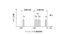
- the engine ECU 100 appropriately calculates the injection amount of fuel injected from the injector 20, the injection pressure, the injection start timing, and the number of injections based on the operating state detected by the operating state detecting means described above. Then, as shown in FIG. 2, the preliminary fuel injection Fp is performed in the first half of the intake stroke, the main injection Fm is performed during the compression stroke, and after the main injection Fm, the ignition control injection Fc near the compression top dead center. Carry out.
- FIG. 2 the preliminary fuel injection Fp is performed in the first half of the intake stroke
- the main injection Fm is performed during the compression stroke
- the ignition control injection Fc near the compression top dead center. Carry out.
- the vertical axis represents the generation of the injection pulse for driving the injector 20
- the horizontal axis represents the energization of the injector 20 indicated by the crank angle (CA) with the compression top dead center as the reference (0 °).
- CA crank angle
- This energization period corresponds to the injection period in which fuel is injected from the injector 20 into the auxiliary combustion chamber 10.
- the fuel injection control of the present embodiment will be described more specifically below.
- FIG. 3 shows a calculation flow executed by the engine ECU 100.
- the engine ECU 100 requests the required load L in consideration of the engine rotation speed Ne detected by the crank angle sensor 102, the lever opening of the accelerator lever opening sensor 105, the work load on the diesel engine 1, and the like.
- the main injection quantity is calculated by subtracting the pre-injection Fp and the fuel quantity supplied by the ignition control injection Fc from the total injection quantity required by the diesel engine 1 to obtain the required main injection quantity Qm.
- the injection amount injected by the preliminary injection Fp and the ignition control injection Fc may be a fixed value or a value that is increased or decreased depending on the operating state. In any case, the required main injection amount Qm is set to be a relatively large value with respect to the injection amounts implemented by the preliminary injection Fp and the ignition control injection Fc.
- the engine rotation speed Ne and the required load L are also input to the required main injection pressure calculation means 122, and the injection pressure of the main injection required by the diesel engine 1 is input. Is output as the required main injection pressure Pm.
- the required main injection pressure Pm is set to be low when the required load L is low and the engine rotation speed Ne is low, and conversely is set to be high when the required load L is high and the engine rotation speed Ne is high. It is set by a map or the like (not shown). If the required main injection pressure Pm is output, the required main injection pressure Pm is set as the target fuel pressure of the fuel passage pipe 30, and the detected value of the fuel passage pipe pressure sensor 101 installed in the fuel passage pipe 30.
- the pressure feed control valve 43 of the fuel pump 41 is controlled based on As a result, the pressure in the fuel passage pipe 30 is constantly adjusted within a predetermined range near the required main injection pressure Pm.
- the required main injection amount Qm and the required main injection pressure Pm are input to the main injection number calculation means 123, and the main injection Fm is given a predetermined number of times.
- the main injection number FNm for dividing and injecting is calculated.
- the required main injection amount Qm and the required main injection pressure Pm input to the main injection number calculation means 123 are first input to the required main injection time calculation means 123a.
- the required main injection time calculation means 123a refers to a TQ map as shown on the right side of the drawing.
- the TQ map is recorded in the engine ECU 100 in advance, and the injector 20 set corresponding to the injection amount (mm 3 ) injected from the injector 20 and the pressure (P1 to P4: MPa) of the fuel passage pipe 30 is set.
- Is a map for specifying the energization time of, that is, the injection time ( ⁇ s), and is set by an experiment or the like.
- the injection time for realizing the amount Qm, that is, the required main injection time FmT is obtained.
- the required main injection time FmT is obtained, the required main injection time FmT is input together with the required main injection pressure Pm to the spray tip reaching distance calculating means 123b, and the injector 20 is injected by referring to a map (not shown).
- the spray tip reaching distance FD of the spray to be calculated is calculated.
- the spray tip reaching distance FD is a value that increases as the required main injection pressure Pm is higher and the required main injection time FmT is longer.
- the distance that the tip of the spray actually reaches is also affected by the diameter and shape of the nozzle formed at the tip of the injector 20. Therefore, the map for determining the spray tip reaching distance FD is for each injector 20 such as an experiment. It is formulated by.
- the spray tip reaching distance FD is input to the main injection number calculation means 123c and the main injection number FNm is calculated.
- the spray tip reaching distance limit value FDL is referred to.
- the spray tip reaching distance limit value FDL will be described with reference to FIG.
- the spray tip reaching distance limit value FDL is not necessarily limited to using the distance from the tip portion of the injector 20 to the wall surface 10a of the opposing auxiliary combustion chamber 10 as it is. Considering the influence on the combustion when the spray F adheres to the wall surface 10a of the auxiliary combustion chamber 10, it is set to a value slightly smaller than the distance from the tip of the injector 20 to the opposite wall surface 10a of the auxiliary combustion chamber 10. It is also possible to set it to a slightly larger value.
- the spray tip reaching distance limit value FDL set as described above is compared with the spray tip reaching distance FD, and when the spray tip reaching distance FD is smaller than the spray tip reaching distance limit value FDL, the requested main injection Even if the quantity Qm is injected once, the fuel injected from the injector 20 does not reach the wall surface of the auxiliary combustion chamber 10, so the number of main injections FNm is set to once. Further, if the spray tip reaching distance FD is equal to or greater than the spray tip reaching distance limit value FDL, the spray F reaches the wall surface 10a of the auxiliary combustion chamber 10 when the main injection number FNm is injected once. ..
- the main injection number FNm is set to a predetermined plurality of times so that the main injection Fm injected from the injector 20 becomes a multi-stage injection, and the required main injection amount Qm is divided according to the divided number.
- the specific number of times the main injection number FNm is set can be determined by how much the spray tip reaching distance FD exceeds the spray tip reaching distance limit value FDL, but twice, three times ...
- the injection time per each injection is calculated by referring to the TQ map based on the fuel injection amount per injection, and the spray tip reach distance FD is calculated again to It may be confirmed by comparing with the tip reaching distance limit value FDL whether the tip of the spray F reaches the wall surface of the auxiliary combustion chamber 10.
- the main injection number FNm may be set to twice. As described above, the predetermined number of times (main injection number FNm) when the main injection Fm is injected by the main injection number calculation means 123 is output.
- the single injection amount calculation means 124 calculates the fuel injection amount Qm1 per injection when the main injection is performed in multiple stages. ..
- the fuel injection amount Qm1 per injection is obtained by dividing the required main injection amount Qm by the main injection number FNm.
- the main injection time Fmt per injection is calculated, the main injection number FNm is calculated and input to the total main injection time calculating means 126, and the main injection Fm is referred to by referring to the target injection interval FI.
- the total main injection time FT from the start to the completion of all the main injections is calculated.
- the total main injection time FT when the number of main injections FNm is 2 is calculated as follows.
- Total main injection time FT main injection time Fmt ⁇ 2 + target injection interval FI
- the target injection interval FI is determined in consideration of the minimum interval that should be opened in order to operate the injector 20 and inject the fuel according to the TQ map, but is not limited to this and the above-mentioned minimum
- the interval may be increased or decreased in accordance with the operating condition in addition to the interval.
- the main injection start timing calculation means 127 As described above, when the total main injection time FT is calculated, it is input to the main injection start timing calculation means 127 and the target main injection end timing FE is referred to, so that the main injection Fm is set as the injection start timing.
- the injection start timing FS is calculated. The procedure for calculating the main injection start timing FS will be described below.
- the total main injection time FT is calculated based on the time ( ⁇ s).
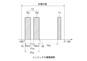
- the control of the fuel injection timing of the injector 20 is performed based on the crank angle (CA) detected by the crank angle sensor 102. Therefore, when calculating the main injection start timing FS, it is necessary to convert and set the crank angle. Regarding this, the procedure for calculating the main injection start timing FS while converting it into the crank angle will be described with reference to FIG. 6 as well.
- the horizontal axis represents the crank angle (CA)
- the preliminary injection Fp performed in the intake stroke is omitted
- the main injection Fm performed in the compression stroke and the pulse of the ignition control injection Fc are illustrated. Shows only.
- the fuel injection performed in the present embodiment is premised on performing the preliminary injection Fp, the main injection Fm, and the ignition control injection Fc, and the main injection Fm is the compression self-ignition near the compression top dead center.
- the target main injection end timing FE that is a predetermined time T0 before the injection start timing of the ignition control injection Fc that is performed at the timing.
- This predetermined time T0 is sufficiently mixed with the swirl flow S (see FIG. 5) of air introduced into the auxiliary combustion chamber 10 in the auxiliary combustion chamber 10 in addition to the above-described target injection interval FI. It is a time that is set considering the time for In this way, the target main injection end timing FE, which is traced back by the predetermined time T0 with respect to the injection start timing of the ignition control injection Fc, is set.
- the injection start timing of the ignition control injection Fc is defined based on the crank angle.
- a predetermined period T0 CA obtained by converting the predetermined time T0 per crank angle (CA) is obtained.
- the predetermined period T0 CA is a value that increases as the engine rotation speed Ne increases and decreases as the engine rotation speed decreases even if the predetermined time T0 is constant.
- the timing that is traced back by T0 CA from the injection start timing of the ignition control injection Fc is set as the target main injection end timing FE.
- the target main injection end timing FE it is not always necessary to use the injection start timing of the ignition control injection Fc as a reference, and the injection start timing of the ignition control injection Fc emission is narrow near the compression top dead center. If it changes only within the range, it may be determined based on the compression top dead center (0 °).
- the total main injection time FT is elapsed from the target main injection end timing FE so that the main injection Fm is completed at this target main injection end timing FE.
- the timing that goes back is calculated as the main injection start timing FS.
- the total main injection time FT is converted per crank angle (CA) in the same manner as the above-mentioned predetermined time T0, and the total main injection period FT is calculated. Calculate CA.
- the main injection start timing FS is determined by the crank angle.
- the target main injection end timing FE is set by the crank angle by the calculation means of the main injection start timing FS, and the target main injection end timing FE is set so that the main injection Fm is completed at the target main injection end timing FE.
- the timing that goes back by the main injection time FT is calculated as the main injection start timing FS. Therefore, the main injection start timing FS of the main injection Fm is advanced from the top dead center side to the bottom dead center side of the compression stroke as the engine rotation speed Ne changes from the low rotation speed to the high rotation speed. become.
- the first main injection Fm1 of the divided main injections Fm is started at the main injection start timing FS described above.
- the injection period of the first main injection Fm1 is obtained by converting the main injection time Fmt per time calculated by the above-described main injection time calculation means 125 into a crank angle 1 according to the engine rotation speed Ne. This is the main injection period Fmt CA per time.
- the target injection interval FI is opened until the injection of the second main injection Fm2 is started.
- the target injection interval FI calculates a target injection interval FI CA converted into the crank angle, by the target injection interval FI CA intervals
- the second main injection Fm2 is executed in the main injection period Fmt CA per time.
- the main injection Fm executed in this way is completed at the target main injection end timing FE, as shown in FIG.
- the ignition control injection Fc is executed to satisfy the ignition condition, and the premixed compression autoignition combustion with the ignition timing appropriately controlled is realized with high thermal efficiency.
- a glow plug 25 is provided in the auxiliary combustion chamber 10 of the diesel engine 1 according to this embodiment.
- the engine ECU 100 determines that the diesel engine 1 is in the low temperature start or is in the warm air mode after the low temperature start, based on the exhaust temperature detected by the exhaust temperature sensor 103 provided as the operating state detection means. , The engine speed Ne and the required load L, even when the operating state is to carry out the preliminary injection Fp, the preliminary injection Fp is not carried out and the glow plug 25 is operated to heat the auxiliary combustion chamber 10. To do. At this time, the fuel set as the preliminary injection Fp is added to the required main injection amount Qm of the main injection Fm.
- the preliminary injection Fp When it is determined that the temperature is low, only the preliminary injection Fp may be prohibited and the main injection Fm and the ignition control injection Fc may be performed. However, the premixed compression self-ignition combustion is stopped and the compression top dead center is reached. Normal diffusion combustion may be performed in which all fuel is injected near the point. This avoids the problem that the fuel injected in the auxiliary combustion chamber 10 does not evaporate sufficiently due to the low temperature of the diesel engine 1 and uniform premixing cannot be formed, and the unburned fuel contained in the exhaust gas is not burned. Prevents HC from increasing.
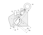
- the center axis C1 of the fuel spray F injected from the injector 20 and the hole center axis C2 of the communication hole 12 are offset.
- the fuel is mixed in the auxiliary combustion chamber 10 to a level sufficient for premixed compression ignition by the vortex flow S of the air flowing into the auxiliary combustion chamber 10 from the main combustion chamber 14 as the piston 5 rises.
- the EGR system 80 that recirculates the exhaust gas from the exhaust system 80 to the intake system 50 is arranged, and the exhaust gas can be supplied to the intake passage 52 according to the operating state.
- the emission of nitrogen oxides contained in the exhaust gas is reduced, and when the premixing is formed by the preliminary injection Fp and the main injection Fm and the compression ignition is performed near the compression top dead center, the EGR gas is also reduced. It is possible to control the ignition timing satisfactorily by, for example, preventing the premature ignition by turning on.
- the injection pressure of the fuel injected from the injector 20 is set within a range of 8 MPa to 40 MPa, and more preferably within a range of 15 MPa to 25 MPa.
- desired combustion performance can be obtained even in such an injection pressure range. That is, since the injection pressure can be set significantly lower than that of the direct injection type diesel engine of which the maximum injection pressure exceeds 200 MPa, it is not necessary to make the structure of the injector 20 itself excessively robust, and it is possible to electrically connect the fuel passage pipe 30 to A system for injecting fuel using the injector 20 that can be driven to a low temperature can be simply configured, and the manufacturing cost can be kept low.
Abstract
Provided is a subchamber diesel engine (1) having excellent thermal efficiency and capable of appropriately controlling the ignition timing of fuel supplied to a combustion subchamber. A subchamber diesel engine (1) according to the present invention comprises a main combustion chamber (14) and a combustion subchamber (10) communicated with each other by a communication hole (12), the diesel engine including: an electrically driven injector (20) for injecting fuel into the combustion subchamber (10) at a random timing; a fuel passage pipe (30) connected to a fuel inlet of the injector (20); a fuel pump (41) for supplying fuel to the fuel passage pipe (30); an engine operating state detecting means for detecting an engine operating state; and a control means (100), wherein the control means (100) performs a preliminary fuel injection (Fp) in the first half of an intake stroke, performs a main injection (Fm) during a compression stroke, and after the main injection (Fm), performs an ignition control injection (Fc) near a compression top dead center.
Description
本発明は、連絡孔によって連通される主燃焼室及び副燃焼室を備えた副室式ディーゼル機関に関する。
The present invention relates to a sub-chamber diesel engine including a main combustion chamber and a sub combustion chamber that are communicated with each other by a communication hole.
従来から、連絡孔によって連通される主燃焼室及び副燃焼室を備えた副室式ディーゼル機関が知られている。
❖ Conventionally, a sub-chamber type diesel engine having a main combustion chamber and a sub combustion chamber that are communicated with each other by a communication hole is known.
一般的な渦流室式の副室式ディーゼル機関は、ピストン上に形成される主燃焼室と、主燃焼室と連絡孔によって連通される副燃焼室と、副燃焼室に燃料を噴射するインジェクタと、を備え、圧縮行程において連通孔を介して主燃焼室側から副燃焼室に空気が進入して、副燃焼室内に強い渦流を発生させる。そして、副燃焼室に臨むように配設されたインジェクタから、渦流が発生している副燃焼室に対して燃料を噴射して混合気を形成し、圧縮上死点近傍で圧縮自着火させて燃焼を開始させる。次いで、副燃焼室にて発生した燃焼ガスの燃焼エネルギーにより、副燃焼室から連通孔を介して主燃焼室に燃焼ガスを進入させて、ピストンを駆動しながら燃焼を完遂させ、動力を得る(例えば、特許文献1、及び特許文献2を参照。)。
A general swirl chamber type sub-chamber diesel engine includes a main combustion chamber formed on a piston, a sub combustion chamber communicating with the main combustion chamber through a communication hole, and an injector for injecting fuel into the sub combustion chamber. , And the air enters the auxiliary combustion chamber from the main combustion chamber side through the communication hole in the compression stroke to generate a strong vortex flow in the auxiliary combustion chamber. Then, from the injector arranged so as to face the auxiliary combustion chamber, fuel is injected into the auxiliary combustion chamber in which the vortex flow is generated to form an air-fuel mixture, and compression ignition is performed near the compression top dead center. Start burning. Then, by the combustion energy of the combustion gas generated in the auxiliary combustion chamber, the combustion gas is introduced from the auxiliary combustion chamber into the main combustion chamber through the communication hole to complete combustion while driving the piston to obtain power ( See, for example, Patent Documents 1 and 2.
特許文献1に記載された副室式ディーゼル機関では、副室式ディーゼル機関の燃焼改善のために、副燃焼室に臨むインジェクタを2本配設し、吸気行程後期から圧縮行程前期にかけて1回目の燃料を副室壁面に向けて噴射し、次いで圧縮行程後期から膨張行程前期にかけて2回目の燃料を副燃焼室に噴射することで燃焼の改善を図っている。
In the sub-chamber diesel engine described in Patent Document 1, two injectors facing the sub-combustion chamber are provided to improve combustion in the sub-chamber diesel engine, and the first intake stroke is performed from the late intake stroke to the early compression stroke. Combustion is improved by injecting fuel toward the wall surface of the sub chamber and then injecting fuel into the sub combustion chamber for the second time from the latter half of the compression stroke to the first half of the expansion stroke.
また、特許文献2に記載された副室式ディーゼル機関では、副燃焼室に臨むインジェクタから予備噴射が実施されることで混合気形成が阻害されることを抑制すべく、始動領域では、該予備噴射を実施しないようにすることで、未燃燃料や未燃ガスの排出を低減する。
Further, in the sub-chamber diesel engine described in Patent Document 2, in the starting region, in order to suppress the inhibition of the mixture formation due to the pre-injection from the injector facing the sub-combustion chamber, Emissions of unburned fuel and unburned gas are reduced by not performing injection.
上記したように、副室式ディーゼル機関において予備噴射を実施することにより、予め混合気を形成して圧縮自着火させる、いわゆる予混合圧縮自着火燃焼を行うことができる。しかし、予混合御圧縮自着火を行う場合、運転状態によっては、燃料の着火時期が早くなりすぎ、熱効率が大きく低下することがある。そのため、自着火しにくい燃料を使用したり、圧縮比を下げたりすることで、着火時期を遅らせることが提案されている。しかし、燃料を変更したり、機関の圧縮比を下げたりすることは、機関を採用する条件が狭められたり、機関の性能を低下させることに繋がり、容易に採用できるものではない。また、予備噴射を実施する場合において、適切な燃焼が実施されるように、燃料を副燃焼室に噴射する噴射条件を細かく変更することが考えられるが、前記特許文献1及び特許文献2に記載された従来の副室式ディーゼル機関では、機械式のジャーク式燃料噴射装置が採用されており、エンジンの回転速度に燃料噴射特性が支配されるため、自在に変更することができず、運転条件に応じた最適な燃料噴射制御を実施することができない。
As described above, by performing preliminary injection in the sub-chamber diesel engine, it is possible to perform so-called premixed compression ignition combustion, in which a mixture is formed in advance and compression ignition is performed. However, when premixed compression compression ignition is performed, the ignition timing of the fuel may be too early and the thermal efficiency may be significantly reduced depending on the operating state. Therefore, it has been proposed to delay the ignition timing by using a fuel that does not easily self-ignite or by reducing the compression ratio. However, changing the fuel or reducing the compression ratio of the engine narrows the conditions for adopting the engine and reduces the performance of the engine, and cannot be easily adopted. Further, when performing the preliminary injection, it is conceivable to finely change the injection conditions for injecting the fuel into the auxiliary combustion chamber so that appropriate combustion is performed, but it is described in Patent Document 1 and Patent Document 2 above. In the conventional sub-chamber type diesel engine, the mechanical jerk type fuel injection device is adopted, and since the fuel injection characteristics are governed by the engine speed, it cannot be changed freely and the operating conditions cannot be changed. The optimum fuel injection control according to the above cannot be implemented.
本発明は、上記事実に鑑みなされたものであり、その主たる技術課題は、副燃焼室に供給する燃料の着火時期を適切に制御することができる熱効率に優れた副室式ディーゼル機関を提供することにある。
The present invention has been made in view of the above facts, and its main technical problem is to provide a sub-chamber diesel engine with excellent thermal efficiency that can appropriately control the ignition timing of the fuel supplied to the sub-combustion chamber. Especially.
上記主たる技術課題を解決するため、本発明によれば、連絡孔によって連通される主燃焼室及び副燃焼室を備えた副室式ディーゼル機関において、任意のタイミングで副燃焼室に燃料を噴射する電気的に駆動されるインジェクタと、前記インジェクタの燃料入口に接続される燃料通路管と、前記燃料通路管に燃料を供給する燃料ポンプと、機関運転状態を検出する機関運転状態検出手段と、制御手段と、を備え、前記制御手段により、吸気行程前半に燃料の予備噴射を実施し、圧縮行程中にメイン噴射を実施し、前記メイン噴射の後、圧縮上死点近傍で着火制御用噴射を実施する副室式ディーゼル機関が提供される。
In order to solve the above-mentioned main technical problem, according to the present invention, in a sub-chamber diesel engine including a main combustion chamber and a sub-combustion chamber which are communicated by a communication hole, fuel is injected into the sub-combustion chamber at an arbitrary timing. An electrically driven injector, a fuel passage pipe connected to a fuel inlet of the injector, a fuel pump for supplying fuel to the fuel passage pipe, an engine operating state detecting means for detecting an engine operating state, and a control The control means performs preliminary fuel injection in the first half of the intake stroke, main injection is performed during the compression stroke, and ignition control injection is performed near the compression top dead center after the main injection. A sub-chamber diesel engine to perform is provided.
前記インジェクタから噴射される燃料の噴霧中心軸と、前記連絡孔の孔中心軸とは、オフセットしていることが好ましい。また、前記副燃焼室には、グロープラグが配設され、前記制御手段は、前記運転状態検出手段により検出される排気温度が所定の温度以下の場合には、前記予備噴射を実施せず、前記グロープラグを作動して、副燃焼室を加熱することが好ましい。
The center axis of the fuel sprayed from the injector and the center axis of the communication hole are preferably offset. Further, a glow plug is provided in the auxiliary combustion chamber, and the control means does not perform the preliminary injection when the exhaust gas temperature detected by the operating state detection means is equal to or lower than a predetermined temperature, It is preferable to operate the glow plug to heat the auxiliary combustion chamber.
また、前記制御手段は、前記運転状態検出手段により検出した運転状態に基づいて、インジェクタから噴射されるメイン噴射の噴射開始時期、噴射量、噴射圧を制御するものであり、前記制御手段により算出されるメイン噴射の噴射量及びその時に要求される噴射圧に応じて、メイン噴射を所定の回数に分割して噴射することが好ましい。前記制御手段は、前記運転状態検出手段により検出されるエンジン回転速度が、低回転から高回転へと変化するに伴い、前記メイン噴射の噴射開始時期を、圧縮行程の上死点側から下死点側へと進角させるようにしてもよい。さらに、前記インジェクタから噴射される噴射圧は、8MPa乃至40MPaの間で設定されることが好ましい。
The control means controls the injection start timing, the injection amount, and the injection pressure of the main injection injected from the injector based on the operating state detected by the operating state detecting means, and is calculated by the controlling means. It is preferable to divide the main injection into a predetermined number of times and inject according to the injection amount of the main injection and the injection pressure required at that time. The control means changes the injection start timing of the main injection from the top dead center side to the bottom dead center of the compression stroke as the engine rotation speed detected by the operating state detection means changes from low rotation speed to high rotation speed. The angle may be advanced to the point side. Further, the injection pressure injected from the injector is preferably set to 8 MPa to 40 MPa.
本発明のディーゼル機関によれば、副燃焼室に供給する燃料の着火時期を適切に制御することができる熱効率に優れた副室式ディーゼル機関が提供される。
According to the diesel engine of the present invention, a sub-chamber diesel engine with excellent thermal efficiency that can appropriately control the ignition timing of the fuel supplied to the sub-combustion chamber is provided.
本発明に従って構成された副室式のディーゼル機関の好適な実施形態について添付図面を参照しながら、以下に説明する。
A preferred embodiment of a sub-chamber type diesel engine configured according to the present invention will be described below with reference to the accompanying drawings.
図1には、主燃焼室及び副燃焼室を備えた副室式のディーゼル機関1の全体概略図が示されている。ディーゼル機関1は、エンジン本体部2、燃料供給系40、吸気系50、排気系60、過給機70、EGR系80、制御手段(エンジンECU)100を備えている。
FIG. 1 shows an overall schematic view of a sub-chamber type diesel engine 1 including a main combustion chamber and a sub combustion chamber. The diesel engine 1 includes an engine body 2, a fuel supply system 40, an intake system 50, an exhaust system 60, a supercharger 70, an EGR system 80, and control means (engine ECU) 100.
エンジン本体部2は、シリンダブロック3、シリンダヘッド4、ピストン5、吸気ポート6、吸気弁7、排気ポート8(破線で示す)、及び排気弁(図示は省略する。)を備えている。排気弁は紙面に垂直な方向で、吸気弁7と並列に配設されており、図示しない動弁機構により、吸気弁7と共に開閉される。
The engine body 2 includes a cylinder block 3, a cylinder head 4, a piston 5, an intake port 6, an intake valve 7, an exhaust port 8 (shown by a broken line), and an exhaust valve (not shown). The exhaust valve is arranged in parallel with the intake valve 7 in a direction perpendicular to the plane of the drawing, and is opened and closed together with the intake valve 7 by a valve mechanism (not shown).
シリンダヘッド4には、略球形状に形成された副燃焼室10が形成されている。主燃焼室14は、シリンダ3a内を摺動するピストン5の頂面5aとシリンダヘッド4の下面4aとの間に形成される。副燃焼室10は、矢印で示すピストン5の摺動方向に対して傾斜する連通孔12を介して主燃焼室14に連通されている。副燃焼室10には、副燃焼室10に燃料を噴射するインジェクタ20と、副燃焼室10内を加熱するためのグロープラグ25が備えられている。
The cylinder head 4 has an auxiliary combustion chamber 10 formed in a substantially spherical shape. The main combustion chamber 14 is formed between the top surface 5a of the piston 5 sliding in the cylinder 3a and the lower surface 4a of the cylinder head 4. The auxiliary combustion chamber 10 communicates with the main combustion chamber 14 via a communication hole 12 that is inclined with respect to the sliding direction of the piston 5 shown by the arrow. The auxiliary combustion chamber 10 is provided with an injector 20 for injecting fuel into the auxiliary combustion chamber 10 and a glow plug 25 for heating the inside of the auxiliary combustion chamber 10.
インジェクタ20には、燃料を蓄圧してインジェクタ20に燃料を供給する燃料通路管30が接続される。燃料通路管30に対し燃料供給系40によって燃料が供給される。燃料供給系40は、燃料ポンプ41、燃料供給管42、圧送量制御弁43、燃料タンク44を備えている。燃料ポンプ41は、ディーゼル機関1のクランク軸9によって図示しない動力伝達機構を介して駆動され、燃料ポンプ41が燃料タンク44から吸引した燃料を、燃料供給管42を介して燃料通路管30に供給する。圧送量制御弁43は電気的に作動するものであり、燃料ポンプ41が吸引した燃料のうち、燃料タンク側にリリーフする量を制御する機能を備え、燃料ポンプ41から燃料通路管30に供給する燃料量を調整することができる。
A fuel passage pipe 30 is connected to the injector 20 so as to accumulate the pressure of the fuel and supply the fuel to the injector 20. Fuel is supplied to the fuel passage pipe 30 by the fuel supply system 40. The fuel supply system 40 includes a fuel pump 41, a fuel supply pipe 42, a pressure feed control valve 43, and a fuel tank 44. The fuel pump 41 is driven by the crankshaft 9 of the diesel engine 1 via a power transmission mechanism (not shown), and supplies the fuel sucked by the fuel pump 41 from the fuel tank 44 to the fuel passage pipe 30 via the fuel supply pipe 42. To do. The pumping amount control valve 43 is electrically operated, has a function of controlling the amount of fuel sucked by the fuel pump 41, which is relieved to the fuel tank side, and supplies the fuel from the fuel pump 41 to the fuel passage pipe 30. The amount of fuel can be adjusted.
図示は省略するが、ディーゼル機関1は、複数のシリンダ3aを備えたいわゆる多気筒エンジンであり、複数のシリンダ3aは、シリンダブロック3に直列に配設される。各シリンダ3aに対応して副燃焼室10が形成され、各副燃焼室10に対してインジェクタ20、及びグロープラグ25が備えられる。各インジェクタ20は、共通する燃料通路管30に接続されており、燃料通路管30に蓄圧された燃料圧力で、副燃焼室10に燃料を噴射する。すなわち、燃料通路管30内の燃料圧力が、インジェクタ20から副燃焼室10に燃料を噴射する際の噴射圧となる。インジェクタ20は、いわゆる内開弁式タイプのインジェクタであり、図示しない電磁ソレノイドによりその作動が電気的に駆動されるものであり、インジェクタ20に送られる電気信号に基づいて任意のタイミングで燃料を噴射することができる。燃料通路管30は、図1の紙面に垂直な方向に延びる管状の部材であり、インジェクタ20の燃料入口が挿入されるインジェクタ取付ボス32が形成されている。インジェクタ取付ボス32は、装着されるインジェクタ20の数に合わせて燃料通路管30の軸方向に均等間隔で形成される。
Although illustration is omitted, the diesel engine 1 is a so-called multi-cylinder engine including a plurality of cylinders 3a, and the plurality of cylinders 3a are arranged in series with the cylinder block 3. A sub combustion chamber 10 is formed corresponding to each cylinder 3a, and an injector 20 and a glow plug 25 are provided for each sub combustion chamber 10. Each injector 20 is connected to a common fuel passage pipe 30, and injects fuel into the auxiliary combustion chamber 10 at the fuel pressure accumulated in the fuel passage pipe 30. That is, the fuel pressure in the fuel passage pipe 30 becomes the injection pressure when the fuel is injected from the injector 20 into the auxiliary combustion chamber 10. The injector 20 is a so-called in-valve type injector, whose operation is electrically driven by an electromagnetic solenoid (not shown), and injects fuel at an arbitrary timing based on an electric signal sent to the injector 20. can do. The fuel passage pipe 30 is a tubular member extending in a direction perpendicular to the paper surface of FIG. 1, and has an injector mounting boss 32 into which the fuel inlet of the injector 20 is inserted. The injector mounting bosses 32 are formed at equal intervals in the axial direction of the fuel passage pipe 30 according to the number of the injectors 20 to be mounted.
吸気系50は、ディーゼル機関1の吸気ポート6に空気(外気)を導入する。この吸気系50は、吸気通路52を備え、吸気通路52には、過給機70のコンプレッサ72と、吸気冷却器(インタークーラ)54が備えられる。なお、吸気通路52には、吸気量を調整する吸気制御弁を備えることもできる。
The intake system 50 introduces air (outside air) into the intake port 6 of the diesel engine 1. The intake system 50 includes an intake passage 52, and the intake passage 52 includes a compressor 72 of the supercharger 70 and an intake cooler (intercooler) 54. The intake passage 52 may be provided with an intake control valve that adjusts the intake amount.
排気系60は、ディーゼル機関1から排出される排気ガスをディーゼル機関1の外部に排出するものである。排気系60は、排気通路62を備えている。排気通路62には、過給機70のタービン74が備えられている。排気通路62はディーゼル機関1の排気ポート8に接続されている。
The exhaust system 60 discharges exhaust gas emitted from the diesel engine 1 to the outside of the diesel engine 1. The exhaust system 60 includes an exhaust passage 62. A turbine 74 of the supercharger 70 is provided in the exhaust passage 62. The exhaust passage 62 is connected to the exhaust port 8 of the diesel engine 1.
EGR系80は、排気通路62を流れる排気ガスの一部をEGRガスとしてディーゼル機関1の吸気ポート6に導入するEGR通路81を備えている。EGR通路81の上流端は、排気通路62に接続されている。EGR通路81の下流端は、吸気通路52の吸気ポート6の上流側に接続されている。EGR通路81にEGRガスを冷却するEGRガスクーラ82が備えられている。EGR通路81には、EGRガスクーラ82をバイパスしてEGRガスを吸気通路52側に流すためのクーラバイパス通路84が設けられている。クーラバイパス通路84には、バイパスするEGRガスの量を調整するバイパス量調整弁86が備えられている。EGR通路81におけるEGRガスクーラ82よりも下流側(吸気通路52側)にはEGRガス量調整弁88が備えられている。EGRガス量調整弁88の開度を制御することにより、吸気通路52を介して吸気ポート6に導入されるEGRガス量を調整することができる。
The EGR system 80 includes an EGR passage 81 that introduces a part of the exhaust gas flowing through the exhaust passage 62 into the intake port 6 of the diesel engine 1 as EGR gas. The upstream end of the EGR passage 81 is connected to the exhaust passage 62. The downstream end of the EGR passage 81 is connected to the upstream side of the intake port 6 of the intake passage 52. The EGR passage 81 is provided with an EGR gas cooler 82 that cools the EGR gas. The EGR passage 81 is provided with a cooler bypass passage 84 for bypassing the EGR gas cooler 82 and allowing EGR gas to flow to the intake passage 52 side. The cooler bypass passage 84 is provided with a bypass amount adjustment valve 86 that adjusts the amount of EGR gas to be bypassed. An EGR gas amount adjustment valve 88 is provided in the EGR passage 81 downstream of the EGR gas cooler 82 (on the intake passage 52 side). By controlling the opening degree of the EGR gas amount adjustment valve 88, the amount of EGR gas introduced into the intake port 6 via the intake passage 52 can be adjusted.
ディーゼル機関1には、ディーゼル機関1全体を制御する制御手段としてのエンジンECU100が備えられている。エンジンECU100は、コンピュータにより構成され、制御プログラムに従って演算処理する中央演算処理装置(CPU)と、制御プログラム等を格納するリードオンリメモリ(ROM)と、検出した検出値、演算結果等を一時的に格納するための読み書き可能なランダムアクセスメモリ(RAM)と、入力インターフェース、及び出力インターフェースとを備えている(詳細についての図示は省略する。)。
The diesel engine 1 is provided with an engine ECU 100 as a control means for controlling the diesel engine 1 as a whole. The engine ECU 100 is composed of a computer, and a central processing unit (CPU) that performs arithmetic processing according to a control program, a read-only memory (ROM) that stores a control program and the like, a detected value detected, a calculation result, etc. temporarily. It is provided with a readable / writable random access memory (RAM) for storing, an input interface, and an output interface (details are not shown).
エンジンECU100は、ディーゼル機関1の運転状態を検出し、検出した運転状態に対応して、予めにROMに記憶された制御プログラムに従って、インジェクタ20から副燃焼室10に供給される燃料の噴射時期、噴射圧力、噴射量、噴射回数、吸気ポートに導入されるEGRガス量等を制御する。
The engine ECU 100 detects the operating state of the diesel engine 1, and in response to the detected operating state, in accordance with a control program stored in advance in the ROM, the injection timing of the fuel supplied from the injector 20 to the auxiliary combustion chamber 10, The injection pressure, the injection amount, the number of injections, the EGR gas amount introduced into the intake port, etc. are controlled.
上記したディーゼル機関1の運転状態を検出する機関運転状態検出手段について説明する。機関運転状態検出手段は、図1に示すように、各種センサを備えることにより構成することができる。各種センサとしては、例えば、燃料通路管30の管内に蓄圧される燃料の圧力を検出する燃料通路管圧力センサ101、クランク軸9の角度位置を検出するクランク角センサ102、排気ポート8から排出される排気ガス温度(例えば、排気マニホールド内温度)を検出する排気温度センサ103、排気通路62から分岐されEGR通路81に導入された排気ガスの温度を検出するEGRガス温度センサ104、アクセルレバー開度センサ105を備えることができる。上記した各種センサは、エンジンECU100に接続され、各種センサで検出された値は、エンジンECU100に入力される。エンジンECU100は、クランク角センサ102からの信号に基づき、基準気筒の基準角度位置、及びエンジン回転速度も算出する。なお、ディーゼル機関1には、前記した各種センサに加え、吸気ポート6に吸入される実吸気量を検出する吸気量センサ、吸気ポート6内の圧力を検出する吸気圧センサ、大気圧を検出する大気圧センサ、及び冷却水温センサ等、他にも各種センサが備えられる(図示は省略する。)。また、運転状態検出手段は、クランク角センサ102とは別に、基準気筒の基準角度位置を検出する基準位置センサ、エンジン回転速度を検出するエンジン回転速度センサを別途備えても良い。また、運転状態検出手段には、エンジンECU100に記憶された制御プログラムにより、運転状態の推定値を算出する手段も含む。
Explain the engine operating state detecting means for detecting the operating state of the diesel engine 1 described above. The engine operating state detecting means can be configured by including various sensors as shown in FIG. The various sensors include, for example, a fuel passage pipe pressure sensor 101 that detects the pressure of fuel accumulated in the fuel passage pipe 30, a crank angle sensor 102 that detects the angular position of the crankshaft 9, and an exhaust port 8. Exhaust gas temperature sensor 103 for detecting the exhaust gas temperature (for example, exhaust manifold internal temperature), EGR gas temperature sensor 104 for detecting the temperature of the exhaust gas branched from the exhaust passage 62 and introduced into the EGR passage 81, accelerator lever opening degree A sensor 105 can be included. The various sensors described above are connected to the engine ECU 100, and the values detected by the various sensors are input to the engine ECU 100. The engine ECU 100 also calculates the reference angular position of the reference cylinder and the engine rotation speed based on the signal from the crank angle sensor 102. In the diesel engine 1, in addition to the various sensors described above, an intake air amount sensor that detects the actual intake air amount taken into the intake port 6, an intake pressure sensor that detects the pressure in the intake port 6, and an atmospheric pressure are detected. Various other sensors such as an atmospheric pressure sensor and a cooling water temperature sensor are provided (not shown). In addition to the crank angle sensor 102, the operating state detection means may separately include a reference position sensor that detects the reference angular position of the reference cylinder and an engine rotation speed sensor that detects the engine rotation speed. The operating state detecting means also includes means for calculating an estimated operating state value by a control program stored in the engine ECU 100.
図2乃至図6を参照しながら、エンジンECU100の作動について説明する。エンジンECU100は、上記した運転状態検出手段により検出した運転状態に基づいて、インジェクタ20から噴射する燃料の噴射量、噴射圧、噴射開始時期、噴射回数を適宜演算する。そして、図2に示すように、吸気行程前半に燃料の予備噴射Fpを実施し、圧縮行程中にメイン噴射Fmを実施し、メイン噴射Fmの後、圧縮上死点近傍で着火制御用噴射Fcを実施する。なお、図2において、縦軸はインジェクタ20を駆動するための噴射パルスの発生を示し、横軸は、圧縮上死点を基準(0°)としたクランク角度(CA)で示すインジェクタ20に対する通電期間を示している。この通電期間が、インジェクタ20から副燃焼室10に燃料を噴射する噴射期間に相当する。以下に、本実施形態の燃料噴射制御についてより具体的に説明する。
The operation of the engine ECU 100 will be described with reference to FIGS. 2 to 6. The engine ECU 100 appropriately calculates the injection amount of fuel injected from the injector 20, the injection pressure, the injection start timing, and the number of injections based on the operating state detected by the operating state detecting means described above. Then, as shown in FIG. 2, the preliminary fuel injection Fp is performed in the first half of the intake stroke, the main injection Fm is performed during the compression stroke, and after the main injection Fm, the ignition control injection Fc near the compression top dead center. Carry out. In FIG. 2, the vertical axis represents the generation of the injection pulse for driving the injector 20, and the horizontal axis represents the energization of the injector 20 indicated by the crank angle (CA) with the compression top dead center as the reference (0 °). The period is shown. This energization period corresponds to the injection period in which fuel is injected from the injector 20 into the auxiliary combustion chamber 10. The fuel injection control of the present embodiment will be described more specifically below.
図3にはエンジンECU100が実施する演算フローが示されている。エンジンECU100は、クランク角センサ102によって検出されるエンジン回転速度Ne、及びアクセルレバー開度センサ105のレバー開度及びディーゼル機関1に掛かる作業負荷等を考慮した要求負荷Lを要求メイン噴射量演算手段121に入力し、ディーゼル機関1が必要とする総噴射量から予備噴射Fpと、着火制御用噴射Fcで供給される燃料量を引くことによりメイン噴射の噴射量を演算し、要求メイン噴射量Qmとして出力する。なお、予備噴射Fp及び着火制御用噴射Fcによって噴射される噴射量は固定値でも良いし、運転状態によって増減される値であっても良い。いずれにしても、要求メイン噴射量Qmは、予備噴射Fp、着火制御用噴射Fcで実施される噴射量に対して、相対的に大きな値となるように設定される。
FIG. 3 shows a calculation flow executed by the engine ECU 100. The engine ECU 100 requests the required load L in consideration of the engine rotation speed Ne detected by the crank angle sensor 102, the lever opening of the accelerator lever opening sensor 105, the work load on the diesel engine 1, and the like. The main injection quantity is calculated by subtracting the pre-injection Fp and the fuel quantity supplied by the ignition control injection Fc from the total injection quantity required by the diesel engine 1 to obtain the required main injection quantity Qm. Output as. The injection amount injected by the preliminary injection Fp and the ignition control injection Fc may be a fixed value or a value that is increased or decreased depending on the operating state. In any case, the required main injection amount Qm is set to be a relatively large value with respect to the injection amounts implemented by the preliminary injection Fp and the ignition control injection Fc.
また、上記した要求メイン噴射量演算手段121と並行して、エンジン回転速度Ne及び要求負荷Lを、要求メイン噴射圧力演算手段122にも入力し、ディーゼル機関1が必要とするメイン噴射の噴射圧を要求メイン噴射圧力Pmとして出力する。要求メイン噴射圧力Pmは、要求負荷Lが低い場合、及びエンジン回転速度Neが低い場合に低くなるように、逆に、要求負荷Lが高い場合、エンジン回転速度Neが高い場合に高くなるようにマップ等(図示は省略する。)で設定される。なお、上記要求メイン噴射圧力Pmが出力されたならば、要求メイン噴射圧力Pmを燃料通路管30の目標燃料圧力として設定し、燃料通路管30に設置された燃料通路管圧力センサ101の検出値に基づいて燃料ポンプ41の圧送量制御弁43を制御する。これにより、燃料通路管30内の圧力は、常に要求メイン噴射圧力Pm近傍の所定範囲内に調整される。
Further, in parallel with the above-mentioned required main injection amount calculation means 121, the engine rotation speed Ne and the required load L are also input to the required main injection pressure calculation means 122, and the injection pressure of the main injection required by the diesel engine 1 is input. Is output as the required main injection pressure Pm. The required main injection pressure Pm is set to be low when the required load L is low and the engine rotation speed Ne is low, and conversely is set to be high when the required load L is high and the engine rotation speed Ne is high. It is set by a map or the like (not shown). If the required main injection pressure Pm is output, the required main injection pressure Pm is set as the target fuel pressure of the fuel passage pipe 30, and the detected value of the fuel passage pipe pressure sensor 101 installed in the fuel passage pipe 30. The pressure feed control valve 43 of the fuel pump 41 is controlled based on As a result, the pressure in the fuel passage pipe 30 is constantly adjusted within a predetermined range near the required main injection pressure Pm.
要求メイン噴射量Qm、及び要求メイン噴射圧力Pmを演算したならば、次いで、要求メイン噴射量Qm、及び要求メイン噴射圧力Pmをメイン噴射回数演算手段123に入力し、メイン噴射Fmを所定の回数に分割して噴射するためのメイン噴射回数FNmを演算する。メイン噴射回数演算手段123の具体的な演算フローについて、図4を参照しながらより具体的に説明する。
Once the required main injection amount Qm and the required main injection pressure Pm have been calculated, then the required main injection amount Qm and the required main injection pressure Pm are input to the main injection number calculation means 123, and the main injection Fm is given a predetermined number of times. The main injection number FNm for dividing and injecting is calculated. A specific calculation flow of the main injection number calculation means 123 will be described more specifically with reference to FIG.
図4に示すように、メイン噴射回数演算手段123に入力された要求メイン噴射量Qm、及び要求メイン噴射圧力Pmは、まず、要求メイン噴射時間演算手段123aに入力される。要求メイン噴射時間演算手段123aでは、図中右方に示すようなT-Qマップを参照する。T-Qマップは、予めエンジンECU100に記録されており、インジェクタ20から噴射される噴射量(mm3)及び燃料通路管30の圧力(P1~P4:MPa)に対応して設定されるインジェクタ20の通電時間、すなわち噴射時間(μs)を特定するためのマップであり、実験等により設定される。入力された要求メイン噴射量Qm、及び要求メイン噴射圧力Pm(例えば、Pm=P2とする。)に基づいて、T-Qマップを参照することで、要求メイン噴射圧力Pmの下で要求メイン噴射量Qmを実現するための噴射時間、すなわち、要求メイン噴射時間FmTが求められる。
As shown in FIG. 4, the required main injection amount Qm and the required main injection pressure Pm input to the main injection number calculation means 123 are first input to the required main injection time calculation means 123a. The required main injection time calculation means 123a refers to a TQ map as shown on the right side of the drawing. The TQ map is recorded in the engine ECU 100 in advance, and the injector 20 set corresponding to the injection amount (mm 3 ) injected from the injector 20 and the pressure (P1 to P4: MPa) of the fuel passage pipe 30 is set. Is a map for specifying the energization time of, that is, the injection time (μs), and is set by an experiment or the like. The required main injection is performed under the required main injection pressure Pm by referring to the TQ map based on the input required main injection amount Qm and the required main injection pressure Pm (for example, Pm = P2). The injection time for realizing the amount Qm, that is, the required main injection time FmT is obtained.
上記した要求メイン噴射時間FmTが求められたならば、要求メイン噴射時間FmTを要求メイン噴射圧力Pmと共に、噴霧先端到達距離演算手段123bに入力し、図示しないマップを参照することでインジェクタ20から噴射される噴霧の噴霧先端到達距離FDを演算する。噴霧先端到達距離FDは、要求メイン噴射圧力Pmが高いほど、又、要求メイン噴射時間FmTが長いほど大きくなる値である。実際に噴霧の先端が到達する距離は、インジェクタ20の先端に形成される噴口径、噴口形状にも影響を受けるため、噴霧先端到達距離FDを求めるためのマップは、インジェクタ20毎に、実験等により策定される。
When the required main injection time FmT is obtained, the required main injection time FmT is input together with the required main injection pressure Pm to the spray tip reaching distance calculating means 123b, and the injector 20 is injected by referring to a map (not shown). The spray tip reaching distance FD of the spray to be calculated is calculated. The spray tip reaching distance FD is a value that increases as the required main injection pressure Pm is higher and the required main injection time FmT is longer. The distance that the tip of the spray actually reaches is also affected by the diameter and shape of the nozzle formed at the tip of the injector 20. Therefore, the map for determining the spray tip reaching distance FD is for each injector 20 such as an experiment. It is formulated by.
噴霧先端到達距離FDを演算したならば、メイン噴射回数演算手段123cに入力し、メイン噴射回数FNmを演算する。ここで、メイン噴射回数演算手段123cにおいてメイン噴射回数FNmを演算する際に、噴霧先端到達距離リミット値FDLを参照する。この噴霧先端到達距離リミット値FDLについて、図5を参照しながら説明する。
Once the spray tip reaching distance FD has been calculated, it is input to the main injection number calculation means 123c and the main injection number FNm is calculated. Here, when the main injection number calculation means 123c calculates the main injection number FNm, the spray tip reaching distance limit value FDL is referred to. The spray tip reaching distance limit value FDL will be described with reference to FIG.
図5に示すように、インジェクタ20の先端部に形成された噴射孔20aから副燃焼室10内に燃料が噴射される。この際、この燃料によって形成される噴霧Fが、副燃焼室10の壁面10aに到達して付着すると、付着した燃料が圧縮上死点近傍で圧縮自着火するまでに十分に蒸発できず、良好に燃焼しないことが懸念される。よって、インジェクタ20から噴射される燃料の噴霧先端到達距離FDが副燃焼室10の壁面10aに達するものであるのか否かを判断する基準として、インジェクタ20の先端部から対向する副燃焼室10の壁面10aまでの距離を噴霧先端到達距離リミット値FDLとして設定する。なお、噴霧先端到達距離リミット値FDLは、必ずしもインジェクタ20の先端部から対向する副燃焼室10の壁面10aまでの距離をそのまま使用することに限定されない。噴霧Fが、副燃焼室10の壁面10aに付着した際の燃焼への影響を考慮して、インジェクタ20の先端部から対向する副燃焼室10の壁面10aまでの距離よりも若干小さい値に設定したり、若干大きい値に設定したりすることも可能である。
As shown in FIG. 5, fuel is injected into the auxiliary combustion chamber 10 through the injection hole 20a formed at the tip of the injector 20. At this time, if the spray F formed by this fuel reaches the wall surface 10a of the auxiliary combustion chamber 10 and adheres thereto, the adhered fuel cannot sufficiently evaporate until compression self-ignition in the vicinity of the compression top dead center. There is concern that it will not burn. Therefore, as a criterion for determining whether the spray tip arrival distance FD of the fuel injected from the injector 20 reaches the wall surface 10a of the auxiliary combustion chamber 10, the auxiliary combustion chamber 10 facing from the tip end of the injector 20 is determined. The distance to the wall surface 10a is set as the spray tip reaching distance limit value FDL. It should be noted that the spray tip reaching distance limit value FDL is not necessarily limited to using the distance from the tip portion of the injector 20 to the wall surface 10a of the opposing auxiliary combustion chamber 10 as it is. Considering the influence on the combustion when the spray F adheres to the wall surface 10a of the auxiliary combustion chamber 10, it is set to a value slightly smaller than the distance from the tip of the injector 20 to the opposite wall surface 10a of the auxiliary combustion chamber 10. It is also possible to set it to a slightly larger value.
上記のようにして設定された噴霧先端到達距離リミット値FDLと、噴霧先端到達距離FDとを比較して、噴霧先端到達距離FDが噴霧先端到達距離リミット値FDLよりも小さい場合は、要求メイン噴射量Qmを1回で噴射しても、インジェクタ20から噴射された燃料は副燃焼室10の壁面に到達しないため、メイン噴射回数FNmを1回とする。また、仮に、噴霧先端到達距離FDが噴霧先端到達距離リミット値FDL以上となった場合は、メイン噴射回数FNmを1回で噴射すると噴霧Fが副燃焼室10の壁面10aに到達することになる。よって、インジェクタ20から噴射されるメイン噴射Fmが、多段噴射となるように、メイン噴射回数FNmを所定の複数の回数とし、分割した回数に応じて要求メイン噴射量Qmを分割する。メイン噴射回数FNmを具体的に何回に設定するのかは、噴霧先端到達距離FDが噴霧先端到達距離リミット値FDLをどの程度超えたかによって決定することができるが、2回、3回・・と増加させる毎に、1回当たりに噴射する燃料噴射量に基づいてT-Qマップを参照して、各1回当たりの噴射時間を算出し、再度、噴霧先端到達距離FDを算出して、噴霧先端到達距離リミット値FDLと比較して噴霧Fの先端が副燃焼室10の壁面に到達しないか確認してもよい。また、要求メイン噴射量Qmが理論上取り得る最大値であっても、2回に分割することで噴霧Fの先端が副燃焼室10の壁面に到達しないことが分かっている場合は、噴霧先端到達距離FDが噴霧先端到達距離リミット値FDL以上と判定された場合に、メイン噴射回数FNmを2回にすればよい。以上のようにして、メイン噴射回数演算手段123によってメイン噴射Fmを噴射する際の所定の回数(メイン噴射回数FNm)が出力される。
The spray tip reaching distance limit value FDL set as described above is compared with the spray tip reaching distance FD, and when the spray tip reaching distance FD is smaller than the spray tip reaching distance limit value FDL, the requested main injection Even if the quantity Qm is injected once, the fuel injected from the injector 20 does not reach the wall surface of the auxiliary combustion chamber 10, so the number of main injections FNm is set to once. Further, if the spray tip reaching distance FD is equal to or greater than the spray tip reaching distance limit value FDL, the spray F reaches the wall surface 10a of the auxiliary combustion chamber 10 when the main injection number FNm is injected once. .. Therefore, the main injection number FNm is set to a predetermined plurality of times so that the main injection Fm injected from the injector 20 becomes a multi-stage injection, and the required main injection amount Qm is divided according to the divided number. The specific number of times the main injection number FNm is set can be determined by how much the spray tip reaching distance FD exceeds the spray tip reaching distance limit value FDL, but twice, three times ... Each time the fuel injection amount is increased, the injection time per each injection is calculated by referring to the TQ map based on the fuel injection amount per injection, and the spray tip reach distance FD is calculated again to It may be confirmed by comparing with the tip reaching distance limit value FDL whether the tip of the spray F reaches the wall surface of the auxiliary combustion chamber 10. Further, even if the requested main injection amount Qm is the theoretically maximum value, if it is known that the tip of the spray F does not reach the wall surface of the auxiliary combustion chamber 10 by dividing into two times, the spray tip When it is determined that the reaching distance FD is equal to or greater than the spray tip reaching distance limit value FDL, the main injection number FNm may be set to twice. As described above, the predetermined number of times (main injection number FNm) when the main injection Fm is injected by the main injection number calculation means 123 is output.
図3に戻り説明を続ける。メイン噴射回数演算手段123によりメイン噴射回数FNmが演算されたならば、1回当たり噴射量演算手段124により、メイン噴射を多段階で実施した場合の1回当たりの燃料噴射量Qm1が演算される。1回当たりの燃料噴射量Qm1は、要求メイン噴射量Qmをメイン噴射回数FNmで除算することにより得られる。1回当たりの燃料噴射量Qm1が算出されたならば、要求メイン噴射圧力Pmと共に1回当たりメイン噴射時間演算手段125に入力され、上記したT-Qマップを参照することにより、1回当たりのメイン噴射時間Fmtが算出される。
Return to Figure 3 and continue the explanation. If the main injection number FNm is calculated by the main injection number calculation means 123, the single injection amount calculation means 124 calculates the fuel injection amount Qm1 per injection when the main injection is performed in multiple stages. .. The fuel injection amount Qm1 per injection is obtained by dividing the required main injection amount Qm by the main injection number FNm. Once the fuel injection amount Qm1 for each injection is calculated, it is input to the main injection time calculation means 125 for each injection together with the required main injection pressure Pm, and by referring to the above TQ map, The main injection time Fmt is calculated.
1回当たりのメイン噴射時間Fmtが算出されたならば、先に算出されたメイン噴射回数FNmと共に、総メイン噴射時間演算手段126に入力し、目標噴射間隔FIを参照して、メイン噴射Fmを開始してから、全てのメイン噴射が完了するまでの総メイン噴射時間FTを演算する。例えば、メイン噴射回数FNmが2回の場合の総メイン噴射時間FTは以下のようにして算出される。
総メイン噴射時間FT=1回当たりのメイン噴射時間Fmt×2+目標噴射間隔FI When the main injection time Fmt per injection is calculated, the main injection number FNm is calculated and input to the total main injectiontime calculating means 126, and the main injection Fm is referred to by referring to the target injection interval FI. The total main injection time FT from the start to the completion of all the main injections is calculated. For example, the total main injection time FT when the number of main injections FNm is 2 is calculated as follows.
Total main injection time FT = main injection time Fmt × 2 + target injection interval FI
総メイン噴射時間FT=1回当たりのメイン噴射時間Fmt×2+目標噴射間隔FI When the main injection time Fmt per injection is calculated, the main injection number FNm is calculated and input to the total main injection
Total main injection time FT = main injection time Fmt × 2 + target injection interval FI
当然のことながら、メイン噴射回数FNmが1回の場合は、目標噴射間隔FIを考慮する必要はなく、1回当たりのメイン噴射時間Fmtがそのまま総メイン噴射時間FTとなる。なお、上記した目標噴射間隔FIは、インジェクタ20を作動してT-Qマップ通りに燃料を噴射するために最低限開けるべき間隔を考慮して決定されるが、これに限定されず、前記最低限開けるべき間隔に加え、運転状態に応じて増減されるものであってもよい。
Needless to say, when the number of main injections FNm is 1, it is not necessary to consider the target injection interval FI, and the main injection time Fmt per injection becomes the total main injection time FT as it is. The above-mentioned target injection interval FI is determined in consideration of the minimum interval that should be opened in order to operate the injector 20 and inject the fuel according to the TQ map, but is not limited to this and the above-mentioned minimum The interval may be increased or decreased in accordance with the operating condition in addition to the interval.
上記したように、総メイン噴射時間FTが算出されたならば、メイン噴射開始時期演算手段127に入力し、目標メイン噴射終わり時期FEを参照することで、メイン噴射Fmの噴射開始時期として、メイン噴射開始時期FSを算出する。メイン噴射開始時期FSを算出する手順について以下に説明する。
As described above, when the total main injection time FT is calculated, it is input to the main injection start timing calculation means 127 and the target main injection end timing FE is referred to, so that the main injection Fm is set as the injection start timing. The injection start timing FS is calculated. The procedure for calculating the main injection start timing FS will be described below.
ところで、上記したように、総メイン噴射時間FTは、時間(μs)を基準に算出されている。これに対し、インジェクタ20の燃料噴射時期の制御は、クランク角センサ102から検出されるクランク角度(CA)に基づいて実施される。よって、メイン噴射開始時期FSを算出するに際しては、クランク角度に変換して設定する必要がある。これについて、図6も併せて参照しながら、メイン噴射開始時期FSをクランク角度に変換しながら演算する手順を説明する。なお、図6では、横軸にクランク角度(CA)を示し、吸気行程において実施される予備噴射Fpについては省略し、圧縮行程中に実施されるメイン噴射Fmと、着火制御用噴射Fcのパルスのみを示している。
By the way, as described above, the total main injection time FT is calculated based on the time (μs). On the other hand, the control of the fuel injection timing of the injector 20 is performed based on the crank angle (CA) detected by the crank angle sensor 102. Therefore, when calculating the main injection start timing FS, it is necessary to convert and set the crank angle. Regarding this, the procedure for calculating the main injection start timing FS while converting it into the crank angle will be described with reference to FIG. 6 as well. In FIG. 6, the horizontal axis represents the crank angle (CA), the preliminary injection Fp performed in the intake stroke is omitted, and the main injection Fm performed in the compression stroke and the pulse of the ignition control injection Fc are illustrated. Shows only.
エンジン回転速度Neが低回転から高回転になるにつれて、ピストン5の平均速度が上昇し、1サイクルに要する時間が変化して小さくなる。他方、上記したように、要求メイン噴射量Qmを全て噴射するために要する時間、すなわち、総メイン噴射時間FT(μs)は、エンジン回転速度Neに直接的に影響を受けず、要求メイン噴射圧力Pmと、要求メイン噴射量Qmに依存する。また、本実施形態において実施される燃料の噴射は、予備噴射Fpと、メイン噴射Fmと、着火制御噴射Fcを実施することを前提とし、メイン噴射Fmは、圧縮上死点近傍の圧縮自着火タイミングで実施される着火制御用噴射Fcの噴射開始時期に対して、所定時間T0だけ前の目標メイン噴射終わり時期FEに完了している必要がある。この所定時間T0は、上記した目標噴射間隔FIに加え、メイン噴射Fmが副燃焼室10内で副燃焼室10内に導入される空気の渦流S(図5を参照。)と十分混合されるための時間も考慮され設定される時間である。このようにして、着火制御用噴射Fcの噴射開始時期を基準として所定時間T0だけ遡った目標メイン噴射終わり時期FEを設定する。ここで、着火制御用噴射Fcの噴射開始時期はクランク角度を基準にして規定されている。そこで、所定時間T0をクランク角(CA)当たりで変換した所定期間T0CAを求める。所定期間T0CAは、所定時間T0が一定であっても、エンジン回転速度Neが上昇すると大きくなり、エンジン回転速度が低下すると小さくなる値である。このようにして、図6に示すように、着火制御用噴射Fcの噴射開始時期からT0CAだけ遡ったタイミングを、目標メイン噴射終わり時期FEとして設定する。なお、目標メイン噴射終わり時期FEの設定に当たっては、必ずしも着火制御用噴Fc射の噴射開始時期を基準とする必要はなく、着火制御用噴Fc射の噴射開始時期が圧縮上死点近傍の狭い範囲でしか変化しないのであれば、圧縮上死点(0°)を基準に決めてもよい。
As the engine rotation speed Ne changes from low rotation to high rotation, the average speed of the piston 5 increases, and the time required for one cycle changes and decreases. On the other hand, as described above, the time required to inject all the required main injection amount Qm, that is, the total main injection time FT (μs), is not directly affected by the engine rotation speed Ne, and the required main injection pressure is Pm and the required main injection amount Qm. Further, the fuel injection performed in the present embodiment is premised on performing the preliminary injection Fp, the main injection Fm, and the ignition control injection Fc, and the main injection Fm is the compression self-ignition near the compression top dead center. It is necessary to complete the target main injection end timing FE that is a predetermined time T0 before the injection start timing of the ignition control injection Fc that is performed at the timing. This predetermined time T0 is sufficiently mixed with the swirl flow S (see FIG. 5) of air introduced into the auxiliary combustion chamber 10 in the auxiliary combustion chamber 10 in addition to the above-described target injection interval FI. It is a time that is set considering the time for In this way, the target main injection end timing FE, which is traced back by the predetermined time T0 with respect to the injection start timing of the ignition control injection Fc, is set. Here, the injection start timing of the ignition control injection Fc is defined based on the crank angle. Therefore, a predetermined period T0 CA obtained by converting the predetermined time T0 per crank angle (CA) is obtained. The predetermined period T0 CA is a value that increases as the engine rotation speed Ne increases and decreases as the engine rotation speed decreases even if the predetermined time T0 is constant. In this way, as shown in FIG. 6, the timing that is traced back by T0 CA from the injection start timing of the ignition control injection Fc is set as the target main injection end timing FE. In setting the target main injection end timing FE, it is not always necessary to use the injection start timing of the ignition control injection Fc as a reference, and the injection start timing of the ignition control injection Fc emission is narrow near the compression top dead center. If it changes only within the range, it may be determined based on the compression top dead center (0 °).
上記したように、目標メイン噴射終わり時期FEをクランク角度で設定したならば、この目標メイン噴射終わり時期FEにメイン噴射Fmが完了するように、目標メイン噴射終わり時期FEから総メイン噴射時間FTだけ遡った時期をメイン噴射開始時期FSとして算出する。上記したように、総メイン噴射時間FTも時間で演算されていることから、上記した所定時間T0と同様に、総メイン噴射時間FTをクランク角(CA)当たりで変換し、総メイン噴射期間FTCAを算出する。総メイン噴射期間FTCAを算出したならば、目標メイン噴射終わり時期FEから上記した総メイン噴射期間FTCAだけ遡ったタイミングをメイン噴射開始時期FSとして算出する。以上の手順により、メイン噴射開始時期FSがクランク角度で決定される。
As described above, if the target main injection end timing FE is set by the crank angle, the total main injection time FT is elapsed from the target main injection end timing FE so that the main injection Fm is completed at this target main injection end timing FE. The timing that goes back is calculated as the main injection start timing FS. As described above, since the total main injection time FT is also calculated by time, the total main injection time FT is converted per crank angle (CA) in the same manner as the above-mentioned predetermined time T0, and the total main injection period FT is calculated. Calculate CA. Once the total main injection period FT CA has been calculated, the timing that goes back from the target main injection end timing FE by the above-mentioned total main injection period FT CA is calculated as the main injection start timing FS. Through the above procedure, the main injection start timing FS is determined by the crank angle.
上記したメイン噴射開始時期FSの演算手段によって、目標メイン噴射終わり時期FEがクランク角度で設定され、この目標メイン噴射終わり時期FEにメイン噴射Fmが完了するように、目標メイン噴射終わり時期FEから総メイン噴射時間FTだけ遡った時期をメイン噴射開始時期FSとして演算している。よって、エンジン回転速度Neが、低回転から高回転へと変化するに伴い、メイン噴射Fmのメイン噴射開始時期FSが、圧縮行程の上死点側から下死点側へと進角されることになる。
The target main injection end timing FE is set by the crank angle by the calculation means of the main injection start timing FS, and the target main injection end timing FE is set so that the main injection Fm is completed at the target main injection end timing FE. The timing that goes back by the main injection time FT is calculated as the main injection start timing FS. Therefore, the main injection start timing FS of the main injection Fm is advanced from the top dead center side to the bottom dead center side of the compression stroke as the engine rotation speed Ne changes from the low rotation speed to the high rotation speed. become.
実際にディーゼル機関1が運転される際には、上記したメイン噴射開始時期FSで、分割されたメイン噴射Fmのうち、1回目のメイン噴射Fm1の噴射が開始される。この1回目のメイン噴射Fm1の噴射期間は、上記した1回当たりのメイン噴射時間演算手段125によって演算された1回当たりのメイン噴射時間Fmtをエンジン回転速度Neに応じたクランク角度に変換した1回当たりのメイン噴射期間FmtCAとなる。そして、1回当たりのメイン噴射期間FmtCAだけ噴射を実施し終了したならば、2回目のメイン噴射Fm2の噴射を開始するまで目標噴射間隔FIだけ間隔を開ける。この際、目標噴射間隔FIも時間で設定されているため、エンジン回転速度Neに応じて、目標噴射間隔FIをクランク角度に変換した目標噴射間隔FICAを演算し、目標噴射間隔FICAだけ間隔を開けた後、2回目のメイン噴射Fm2を1回当たりのメイン噴射期間FmtCAで実行する。このようにして実行されたメイン噴射Fmは、図6に示すように、目標メイン噴射終わり時期FEで完了する。そして、所定期間T0CA後に、着火制御用噴射Fcが実行されることで着火条件が満たされ、着火時期が適切に制御された予混合圧縮自着火燃焼が高い熱効率で実現される。
When the diesel engine 1 is actually operated, the first main injection Fm1 of the divided main injections Fm is started at the main injection start timing FS described above. The injection period of the first main injection Fm1 is obtained by converting the main injection time Fmt per time calculated by the above-described main injection time calculation means 125 into a crank angle 1 according to the engine rotation speed Ne. This is the main injection period Fmt CA per time. When the injection is performed for the main injection period Fmt CA per time and ended, the target injection interval FI is opened until the injection of the second main injection Fm2 is started. At this time, since it is set by the target injection interval FI the time, according to the engine rotational speed Ne, the target injection interval FI calculates a target injection interval FI CA converted into the crank angle, by the target injection interval FI CA intervals After opening, the second main injection Fm2 is executed in the main injection period Fmt CA per time. The main injection Fm executed in this way is completed at the target main injection end timing FE, as shown in FIG. Then, after the predetermined period T0 CA , the ignition control injection Fc is executed to satisfy the ignition condition, and the premixed compression autoignition combustion with the ignition timing appropriately controlled is realized with high thermal efficiency.
図1、及び図5に示したように、本実施形態におけるディーゼル機関1の副燃焼室10には、グロープラグ25が配設されている。エンジンECU100は、運転状態検出手段として配設された排気温度センサ103により検出される排気温度に基づき、ディーゼル機関1が低温始動時、又は低温始動後の暖気モードであると判断される場合には、エンジン回転速度Ne、要求負荷Lによって特定される運転状態が予備噴射Fpを実施する場合であっても、予備噴射Fpを実施せず、グロープラグ25を作動して、副燃焼室10を加熱する。この際、予備噴射Fpとして設定されていた燃料は、メイン噴射Fmの要求メイン噴射量Qmに加算される。また、低温状態と判断された場合に、予備噴射Fpのみを禁止して、メイン噴射Fm、及び着火制御用噴射Fcを実施してもよいが、予混合圧縮自着火燃焼を止め、圧縮上死点近傍で全ての燃料を噴射する、通常の拡散燃焼を実施してもよい。これにより、ディーゼル機関1が低温であることによって副燃焼室10内で噴射された燃料が十分に蒸発せず、均一な予混合を形成できない問題を回避し、また、排気ガスに含まれる未燃HCが増大することを防止する。
As shown in FIGS. 1 and 5, a glow plug 25 is provided in the auxiliary combustion chamber 10 of the diesel engine 1 according to this embodiment. When the engine ECU 100 determines that the diesel engine 1 is in the low temperature start or is in the warm air mode after the low temperature start, based on the exhaust temperature detected by the exhaust temperature sensor 103 provided as the operating state detection means. , The engine speed Ne and the required load L, even when the operating state is to carry out the preliminary injection Fp, the preliminary injection Fp is not carried out and the glow plug 25 is operated to heat the auxiliary combustion chamber 10. To do. At this time, the fuel set as the preliminary injection Fp is added to the required main injection amount Qm of the main injection Fm. When it is determined that the temperature is low, only the preliminary injection Fp may be prohibited and the main injection Fm and the ignition control injection Fc may be performed. However, the premixed compression self-ignition combustion is stopped and the compression top dead center is reached. Normal diffusion combustion may be performed in which all fuel is injected near the point. This avoids the problem that the fuel injected in the auxiliary combustion chamber 10 does not evaporate sufficiently due to the low temperature of the diesel engine 1 and uniform premixing cannot be formed, and the unburned fuel contained in the exhaust gas is not burned. Prevents HC from increasing.
本実施形態では、図5に示すように、インジェクタ20から噴射される燃料の噴霧Fの中心軸C1と、連絡孔12の孔中心軸C2とは、オフセットしている。このような配置により、吸気行程、及び圧縮行程の前半にインジェクタ20から燃料を噴射しても、容易に主燃焼室14に漏れ出ない。したがって、燃料がシリンダ3aに付着して潤滑油が希釈されることが防止される。また、ピストン5の上昇に伴って主燃焼室14から副燃焼室10に流入する空気による渦流Sによって副燃焼室10内で燃料が予混合圧縮自着火に十分なレベルまで混合される。
In the present embodiment, as shown in FIG. 5, the center axis C1 of the fuel spray F injected from the injector 20 and the hole center axis C2 of the communication hole 12 are offset. With such an arrangement, even if fuel is injected from the injector 20 in the first half of the intake stroke and the compression stroke, the fuel does not easily leak to the main combustion chamber 14. Therefore, it is possible to prevent the fuel from adhering to the cylinder 3a and diluting the lubricating oil. Further, the fuel is mixed in the auxiliary combustion chamber 10 to a level sufficient for premixed compression ignition by the vortex flow S of the air flowing into the auxiliary combustion chamber 10 from the main combustion chamber 14 as the piston 5 rises.
本実施形態では、排気系80から吸気系50に排気ガスを還流するEGR系80が配設されており、運転状態に応じて、排気ガスを吸気通路52に供給することができる。これにより、排気ガス中に含まれる窒素酸化物の排出を低減すると共に、予備噴射Fp、メイン噴射Fmによって予混合を形成して圧縮上死点近傍にて圧縮自着火させる際にも、EGRガスの投入によって過早着火を防止する等して、着火時期を良好にコントロールすることが可能になる。
In the present embodiment, the EGR system 80 that recirculates the exhaust gas from the exhaust system 80 to the intake system 50 is arranged, and the exhaust gas can be supplied to the intake passage 52 according to the operating state. As a result, the emission of nitrogen oxides contained in the exhaust gas is reduced, and when the premixing is formed by the preliminary injection Fp and the main injection Fm and the compression ignition is performed near the compression top dead center, the EGR gas is also reduced. It is possible to control the ignition timing satisfactorily by, for example, preventing the premature ignition by turning on.
本実施形態の副室式のディーゼル機関1は、8MPa乃至40MPaの範囲で、より好ましくは、15MPa乃至25MPaの範囲でインジェクタ20から噴射される燃料の噴射圧を設定する。副室式ディーゼル機関1であれば、このような噴射圧の範囲でも、所望の燃焼性能を得ることができる。すなわち、最大噴射圧力が200MPaを超える昨今の直噴式ディーゼル機関に比べ、格段に噴射圧を低く設定できることから、インジェクタ20自身の構造を過剰に堅牢にする必要はなく、燃料通路管30から電気的に駆動可能なインジェクタ20を用いて燃料を噴射するシステムをシンプルに構成することができ、製造コストを低く抑えることができる。
In the sub-chamber type diesel engine 1 of the present embodiment, the injection pressure of the fuel injected from the injector 20 is set within a range of 8 MPa to 40 MPa, and more preferably within a range of 15 MPa to 25 MPa. With the sub-chamber diesel engine 1, desired combustion performance can be obtained even in such an injection pressure range. That is, since the injection pressure can be set significantly lower than that of the direct injection type diesel engine of which the maximum injection pressure exceeds 200 MPa, it is not necessary to make the structure of the injector 20 itself excessively robust, and it is possible to electrically connect the fuel passage pipe 30 to A system for injecting fuel using the injector 20 that can be driven to a low temperature can be simply configured, and the manufacturing cost can be kept low.
1:ディーゼル機関
2:エンジン本体部
3:シリンダブロック
4:シリンダヘッド
5:ピストン
5a:ピストン頂面
6:吸気ポート
7:吸気弁
8:排気ポート
9:クランク軸
10:副燃焼室
12:連通孔
14:主燃焼室
20:インジェクタ
25:グロープラグ
30:燃料通路管
40:燃料供給系
41:燃料ポンプ
42:燃料供給管
43:圧送量制御弁
44:燃料タンク
50:吸気系
52:吸気通路
54:吸気冷却器(インタークーラ)
60:排気系
62:排気通路
70:過給機
72:コンプレッサ
74:タービン
80:EGR系
81:EGR通路
82:EGRガスクーラ
84:クーラバイパス通路
86:バイパス量調整弁
88:EGRガス量調整弁
100:制御手段
101:燃料通路管圧力センサ
102:クランク角センサ
103:排気温度センサ
104:EGRガス温度センサ
105:アクセルレバー開度センサ
Ne:エンジン回転速度
L:要求負荷
Fp:予備噴射
Fm:メイン噴射
Fc:着火制御用噴射
Qm:要求メイン噴射量
Qm1:1回当たりの燃料噴射量
Pm:要求メイン噴射圧
FNm:メイン噴射回数
FmT:要求メイン噴射時間
Fmt:1回当たりのメイン噴射時間
FD:噴霧先端到達距離
FDL:噴霧先端到達距離リミット値
FI:目標噴射間隔
FT:総メイン噴射時間
FS:メイン噴射開始時期
FE:目標メイン噴射終わり時期 1: Diesel engine 2: Engine body 3: Cylinder block 4: Cylinder head 5:Piston 5a: Piston top surface 6: Intake port 7: Intake valve 8: Exhaust port 9: Crankshaft 10: Secondary combustion chamber 12: Communication hole 14: main combustion chamber 20: injector 25: glow plug 30: fuel passage pipe 40: fuel supply system 41: fuel pump 42: fuel supply pipe 43: pressure feed control valve 44: fuel tank 50: intake system 52: intake passage 54 : Intake air cooler (intercooler)
60: exhaust system 62: exhaust passage 70: supercharger 72: compressor 74: turbine 80: EGR system 81: EGR passage 82: EGR gas cooler 84: cooler bypass passage 86: bypass amount adjustment valve 88: EGR gas amount adjustment valve 100 : Control means 101: fuel passage pipe pressure sensor 102: crank angle sensor 103: exhaust gas temperature sensor 104: EGR gas temperature sensor 105: accelerator lever opening sensor Ne: engine speed L: required load Fp: preliminary injection Fm: main injection Fc: Ignition control injection Qm: Required main injection amount Qm 1: Fuel injection amount per injection Pm: Required main injection pressure FNm: Main injection frequency FmT: Required main injection time Fmt: Main injection time FD per spray: Spray Tip reaching distance FDL: Spray tip reaching distance limit value FI: Target injection interval FT: Total main injection time FS: Main injection start timing FE: Target main injection end timing
2:エンジン本体部
3:シリンダブロック
4:シリンダヘッド
5:ピストン
5a:ピストン頂面
6:吸気ポート
7:吸気弁
8:排気ポート
9:クランク軸
10:副燃焼室
12:連通孔
14:主燃焼室
20:インジェクタ
25:グロープラグ
30:燃料通路管
40:燃料供給系
41:燃料ポンプ
42:燃料供給管
43:圧送量制御弁
44:燃料タンク
50:吸気系
52:吸気通路
54:吸気冷却器(インタークーラ)
60:排気系
62:排気通路
70:過給機
72:コンプレッサ
74:タービン
80:EGR系
81:EGR通路
82:EGRガスクーラ
84:クーラバイパス通路
86:バイパス量調整弁
88:EGRガス量調整弁
100:制御手段
101:燃料通路管圧力センサ
102:クランク角センサ
103:排気温度センサ
104:EGRガス温度センサ
105:アクセルレバー開度センサ
Ne:エンジン回転速度
L:要求負荷
Fp:予備噴射
Fm:メイン噴射
Fc:着火制御用噴射
Qm:要求メイン噴射量
Qm1:1回当たりの燃料噴射量
Pm:要求メイン噴射圧
FNm:メイン噴射回数
FmT:要求メイン噴射時間
Fmt:1回当たりのメイン噴射時間
FD:噴霧先端到達距離
FDL:噴霧先端到達距離リミット値
FI:目標噴射間隔
FT:総メイン噴射時間
FS:メイン噴射開始時期
FE:目標メイン噴射終わり時期 1: Diesel engine 2: Engine body 3: Cylinder block 4: Cylinder head 5:
60: exhaust system 62: exhaust passage 70: supercharger 72: compressor 74: turbine 80: EGR system 81: EGR passage 82: EGR gas cooler 84: cooler bypass passage 86: bypass amount adjustment valve 88: EGR gas amount adjustment valve 100 : Control means 101: fuel passage pipe pressure sensor 102: crank angle sensor 103: exhaust gas temperature sensor 104: EGR gas temperature sensor 105: accelerator lever opening sensor Ne: engine speed L: required load Fp: preliminary injection Fm: main injection Fc: Ignition control injection Qm: Required main injection amount Qm 1: Fuel injection amount per injection Pm: Required main injection pressure FNm: Main injection frequency FmT: Required main injection time Fmt: Main injection time FD per spray: Spray Tip reaching distance FDL: Spray tip reaching distance limit value FI: Target injection interval FT: Total main injection time FS: Main injection start timing FE: Target main injection end timing
Claims (6)
- 連絡孔によって連通される主燃焼室及び副燃焼室を備えた副室式ディーゼル機関において、
任意のタイミングで副燃焼室に燃料を噴射する電気的に駆動されるインジェクタと、前記インジェクタの燃料入口に接続される燃料通路管と、前記燃料通路管に燃料を供給する燃料ポンプと、機関運転状態を検出する機関運転状態検出手段と、制御手段と、を備え、
前記制御手段により、吸気行程前半に燃料の予備噴射を実施し、圧縮行程中にメイン噴射を実施し、前記メイン噴射の後、圧縮上死点近傍で着火制御用噴射を実施する副室式ディーゼル機関。 In a sub-chamber diesel engine equipped with a main combustion chamber and a sub-combustion chamber that are communicated by a communication hole,
An electrically driven injector that injects fuel into the auxiliary combustion chamber at an arbitrary timing, a fuel passage pipe connected to the fuel inlet of the injector, a fuel pump that supplies fuel to the fuel passage pipe, and engine operation An engine operating state detecting means for detecting the state, and a control means,
A sub-chamber diesel that performs preliminary injection of fuel in the first half of the intake stroke by the control means, performs main injection during the compression stroke, and performs ignition control injection near the compression top dead center after the main injection. organ. - 前記インジェクタから噴射される燃料の噴霧中心軸と、前記連絡孔の孔中心軸とは、オフセットしている、請求項1に記載の副室式ディーゼル機関。 The sub-chamber diesel engine according to claim 1, wherein a center axis of fuel injected from the injector is offset from a center axis of the communication hole.
- 前記副燃焼室には、グロープラグが配設され、前記制御手段は、前記運転状態検出手段により検出される排気温度が所定の温度以下の場合には、前記予備噴射を実施せず、前記グロープラグを作動して、副燃焼室を加熱する請求項1、又は2に記載の副室式ディーゼル機関。 A glow plug is disposed in the auxiliary combustion chamber, and the control means does not perform the preliminary injection and does not perform the preliminary injection when the exhaust gas temperature detected by the operating state detection means is equal to or lower than a predetermined temperature. The subchamber diesel engine according to claim 1 or 2, wherein the subcombustion chamber is heated by operating the plug.
- 前記制御手段は、前記運転状態検出手段により検出した運転状態に基づいて、インジェクタから噴射されるメイン噴射の噴射開始時期、噴射量、及び噴射圧を制御するものであり、前記制御手段により算出されるメイン噴射の噴射量及びその時に要求される噴射圧に応じて、メイン噴射を所定の回数に分割して噴射する請求項1乃至3のいずれかに記載された副室式ディーゼル機関。 The control means controls the injection start timing, the injection amount, and the injection pressure of the main injection injected from the injector based on the operation state detected by the operation state detection means, and is calculated by the control means. The sub-chamber diesel engine according to any one of claims 1 to 3, wherein the main injection is divided into a predetermined number of times and injected according to the injection amount of the main injection and the injection pressure required at that time.
- 前記制御手段は、前記運転状態検出手段により検出されるエンジン回転速度が、低回転から高回転へと変化するに伴い、前記メイン噴射の噴射開始時期を、圧縮行程の上死点側から下死点側へと進角させる請求項1乃至4のいずれかに記載された副室式ディーゼル機関。 The control means changes the injection start timing of the main injection from the top dead center side to the bottom dead center of the compression stroke as the engine rotation speed detected by the operating state detection means changes from low rotation speed to high rotation speed. The sub-chamber diesel engine according to any one of claims 1 to 4, which advances the angle to the point side.
- 前記インジェクタから噴射される噴射圧は、8MPa乃至40MPaの間で設定される、請求項1乃至5のいずれかに記載された副室式ディーゼル機関。 The sub-chamber diesel engine according to any one of claims 1 to 5, wherein the injection pressure injected from the injector is set between 8 MPa and 40 MPa.
Priority Applications (2)
| Application Number | Priority Date | Filing Date | Title |
|---|---|---|---|
| US17/295,301 US20220003147A1 (en) | 2018-11-20 | 2019-10-24 | Subchamber diesel engine |
| EP19886081.9A EP3885565A4 (en) | 2018-11-20 | 2019-10-24 | Subchamber diesel engine |
Applications Claiming Priority (2)
| Application Number | Priority Date | Filing Date | Title |
|---|---|---|---|
| JP2018-217400 | 2018-11-20 | ||
| JP2018217400A JP2020084848A (en) | 2018-11-20 | 2018-11-20 | Auxiliary chamber type diesel engine |
Publications (1)
| Publication Number | Publication Date |
|---|---|
| WO2020105355A1 true WO2020105355A1 (en) | 2020-05-28 |
Family
ID=70774049
Family Applications (1)
| Application Number | Title | Priority Date | Filing Date |
|---|---|---|---|
| PCT/JP2019/041623 WO2020105355A1 (en) | 2018-11-20 | 2019-10-24 | Subchamber diesel engine |
Country Status (4)
| Country | Link |
|---|---|
| US (1) | US20220003147A1 (en) |
| EP (1) | EP3885565A4 (en) |
| JP (1) | JP2020084848A (en) |
| WO (1) | WO2020105355A1 (en) |
Cited By (1)
| Publication number | Priority date | Publication date | Assignee | Title |
|---|---|---|---|---|
| CN114521525A (en) * | 2022-03-09 | 2022-05-24 | 合肥师范学院 | Bait casting machine and method for fishery |
Citations (11)
| Publication number | Priority date | Publication date | Assignee | Title |
|---|---|---|---|---|
| JPS5851232A (en) * | 1981-09-22 | 1983-03-25 | Nissan Motor Co Ltd | Auxiliary device for starting diesel engine |
| JPH03115723A (en) * | 1989-09-29 | 1991-05-16 | Isuzu Motors Ltd | Auxiliary chamber type insulated engine |
| JPH0633816A (en) * | 1992-07-10 | 1994-02-08 | Mazda Motor Corp | Fuel injection device of auxiliary chamber type diesel engine |
| JPH07116941A (en) | 1993-10-26 | 1995-05-09 | Okuma Mach Works Ltd | Numerical control information making device |
| JPH09158730A (en) * | 1995-12-08 | 1997-06-17 | Isuzu Ceramics Kenkyusho:Kk | Thermally insulated engine with fuel of kerosene or/and vegetable oil |
| JPH09217624A (en) * | 1996-02-09 | 1997-08-19 | Isuzu Ceramics Kenkyusho:Kk | Diesel engine using heavy oil as main fuel |
| JPH09317471A (en) * | 1996-05-24 | 1997-12-09 | Isuzu Ceramics Kenkyusho:Kk | Diesel engine using low quality fuel |
| JP2000054904A (en) * | 1998-08-11 | 2000-02-22 | Kubota Corp | Auxiliary combustion chamber of diesel engine |
| JP2000328973A (en) * | 1999-05-17 | 2000-11-28 | Hideo Kawamura | Diesel engine with egr system |
| JP2000328974A (en) * | 1999-05-17 | 2000-11-28 | Isuzu Ceramics Res Inst Co Ltd | Diesel engine with egr system |
| JP2001193526A (en) * | 2000-01-12 | 2001-07-17 | Mazda Motor Corp | Control device for engine with turbosupercharger |
Family Cites Families (4)
| Publication number | Priority date | Publication date | Assignee | Title |
|---|---|---|---|---|
| JPH07116942B2 (en) * | 1989-09-29 | 1995-12-18 | いすゞ自動車株式会社 | Sub-chamber type adiabatic engine and its fuel injection control device |
| DE19639172C2 (en) * | 1996-09-24 | 2001-11-08 | Siemens Ag | Direct fuel injection method for a diesel internal combustion engine |
| DE102008020221B4 (en) * | 2008-04-22 | 2018-10-25 | Thomas Koch | Method for starting a self-igniting internal combustion engine at low temperatures |
| US9890689B2 (en) * | 2015-10-29 | 2018-02-13 | Woodward, Inc. | Gaseous fuel combustion |
-
2018
- 2018-11-20 JP JP2018217400A patent/JP2020084848A/en active Pending
-
2019
- 2019-10-24 WO PCT/JP2019/041623 patent/WO2020105355A1/en unknown
- 2019-10-24 EP EP19886081.9A patent/EP3885565A4/en not_active Withdrawn
- 2019-10-24 US US17/295,301 patent/US20220003147A1/en not_active Abandoned
Patent Citations (12)
| Publication number | Priority date | Publication date | Assignee | Title |
|---|---|---|---|---|
| JPS5851232A (en) * | 1981-09-22 | 1983-03-25 | Nissan Motor Co Ltd | Auxiliary device for starting diesel engine |
| JPH03115723A (en) * | 1989-09-29 | 1991-05-16 | Isuzu Motors Ltd | Auxiliary chamber type insulated engine |
| JPH0633816A (en) * | 1992-07-10 | 1994-02-08 | Mazda Motor Corp | Fuel injection device of auxiliary chamber type diesel engine |
| JPH07116941A (en) | 1993-10-26 | 1995-05-09 | Okuma Mach Works Ltd | Numerical control information making device |
| JPH09158730A (en) * | 1995-12-08 | 1997-06-17 | Isuzu Ceramics Kenkyusho:Kk | Thermally insulated engine with fuel of kerosene or/and vegetable oil |
| JPH09217624A (en) * | 1996-02-09 | 1997-08-19 | Isuzu Ceramics Kenkyusho:Kk | Diesel engine using heavy oil as main fuel |
| JPH09317471A (en) * | 1996-05-24 | 1997-12-09 | Isuzu Ceramics Kenkyusho:Kk | Diesel engine using low quality fuel |
| JP2000054904A (en) * | 1998-08-11 | 2000-02-22 | Kubota Corp | Auxiliary combustion chamber of diesel engine |
| JP3851727B2 (en) | 1998-08-11 | 2006-11-29 | 株式会社クボタ | Diesel engine subchamber combustion chamber |
| JP2000328973A (en) * | 1999-05-17 | 2000-11-28 | Hideo Kawamura | Diesel engine with egr system |
| JP2000328974A (en) * | 1999-05-17 | 2000-11-28 | Isuzu Ceramics Res Inst Co Ltd | Diesel engine with egr system |
| JP2001193526A (en) * | 2000-01-12 | 2001-07-17 | Mazda Motor Corp | Control device for engine with turbosupercharger |
Non-Patent Citations (1)
| Title |
|---|
| See also references of EP3885565A4 |
Cited By (1)
| Publication number | Priority date | Publication date | Assignee | Title |
|---|---|---|---|---|
| CN114521525A (en) * | 2022-03-09 | 2022-05-24 | 合肥师范学院 | Bait casting machine and method for fishery |
Also Published As
| Publication number | Publication date |
|---|---|
| JP2020084848A (en) | 2020-06-04 |
| EP3885565A4 (en) | 2022-08-10 |
| EP3885565A1 (en) | 2021-09-29 |
| US20220003147A1 (en) | 2022-01-06 |
Similar Documents
| Publication | Publication Date | Title |
|---|---|---|
| US7252069B2 (en) | Gas fuel engine and control method for the same | |
| KR102261770B1 (en) | Internally cooled high compression lean-burning internal combustion engine | |
| KR101693895B1 (en) | Variable ignition type engine for complex combustion using diesel and gasoline, method for controlling of the same and complex combustion system using diesel and gasoline | |
| EP1424481A2 (en) | Diesel engine | |
| US8037864B2 (en) | Diesel engine | |
| JP5392418B2 (en) | Ignition delay period estimation device and ignition timing control device for internal combustion engine | |
| WO2011118031A1 (en) | Combustion control device for internal combustion engine | |
| JP5120506B2 (en) | Combustion control device for internal combustion engine | |
| EP2392808A1 (en) | Control device for internal combustion engine | |
| JP6508186B2 (en) | Control device for internal combustion engine | |
| JP2010196506A (en) | Cylinder injection internal combustion engine | |
| CN101939524B (en) | Fuel injection control apparatus of internal combustion engine | |
| JP5196072B1 (en) | Control device for internal combustion engine | |
| WO2010035342A1 (en) | Fuel injection control device for internal-combustion engine | |
| CN109328263B (en) | Control device | |
| WO2020105355A1 (en) | Subchamber diesel engine | |
| JP5866813B2 (en) | Internal combustion engine | |
| JP5093407B2 (en) | Combustion control device for internal combustion engine | |
| JP5257520B2 (en) | Control device for internal combustion engine | |
| KR20180034495A (en) | Controlling the Combustion of a Compression Ignition Internal Combustion Engine by Controlling Reactivity Through Injection Temperature | |
| WO2020105350A1 (en) | Auxiliary chamber type diesel engine | |
| JP2022097008A (en) | Engine device | |
| JP2021055662A (en) | Fuel reforming engine |
Legal Events
| Date | Code | Title | Description |
|---|---|---|---|
| 121 | Ep: the epo has been informed by wipo that ep was designated in this application |
Ref document number: 19886081 Country of ref document: EP Kind code of ref document: A1 |
|
| NENP | Non-entry into the national phase |
Ref country code: DE |
|
| ENP | Entry into the national phase |
Ref document number: 2019886081 Country of ref document: EP Effective date: 20210621 |