WO2011118031A1 - Combustion control device for internal combustion engine - Google Patents
Combustion control device for internal combustion engine Download PDFInfo
- Publication number
- WO2011118031A1 WO2011118031A1 PCT/JP2010/055399 JP2010055399W WO2011118031A1 WO 2011118031 A1 WO2011118031 A1 WO 2011118031A1 JP 2010055399 W JP2010055399 W JP 2010055399W WO 2011118031 A1 WO2011118031 A1 WO 2011118031A1
- Authority
- WO
- WIPO (PCT)
- Prior art keywords
- injection
- combustion
- amount
- fuel
- diffusion
- Prior art date
Links
Images


Classifications
-
- F—MECHANICAL ENGINEERING; LIGHTING; HEATING; WEAPONS; BLASTING
- F02—COMBUSTION ENGINES; HOT-GAS OR COMBUSTION-PRODUCT ENGINE PLANTS
- F02D—CONTROLLING COMBUSTION ENGINES
- F02D41/00—Electrical control of supply of combustible mixture or its constituents
- F02D41/30—Controlling fuel injection
- F02D41/3011—Controlling fuel injection according to or using specific or several modes of combustion
- F02D41/3017—Controlling fuel injection according to or using specific or several modes of combustion characterised by the mode(s) being used
- F02D41/3035—Controlling fuel injection according to or using specific or several modes of combustion characterised by the mode(s) being used a mode being the premixed charge compression-ignition mode
-
- F—MECHANICAL ENGINEERING; LIGHTING; HEATING; WEAPONS; BLASTING
- F02—COMBUSTION ENGINES; HOT-GAS OR COMBUSTION-PRODUCT ENGINE PLANTS
- F02D—CONTROLLING COMBUSTION ENGINES
- F02D41/00—Electrical control of supply of combustible mixture or its constituents
- F02D41/30—Controlling fuel injection
- F02D41/3011—Controlling fuel injection according to or using specific or several modes of combustion
- F02D41/3064—Controlling fuel injection according to or using specific or several modes of combustion with special control during transition between modes
-
- F—MECHANICAL ENGINEERING; LIGHTING; HEATING; WEAPONS; BLASTING
- F02—COMBUSTION ENGINES; HOT-GAS OR COMBUSTION-PRODUCT ENGINE PLANTS
- F02D—CONTROLLING COMBUSTION ENGINES
- F02D41/00—Electrical control of supply of combustible mixture or its constituents
- F02D41/30—Controlling fuel injection
- F02D41/38—Controlling fuel injection of the high pressure type
- F02D41/40—Controlling fuel injection of the high pressure type with means for controlling injection timing or duration
- F02D41/402—Multiple injections
- F02D41/403—Multiple injections with pilot injections
-
- F—MECHANICAL ENGINEERING; LIGHTING; HEATING; WEAPONS; BLASTING
- F02—COMBUSTION ENGINES; HOT-GAS OR COMBUSTION-PRODUCT ENGINE PLANTS
- F02B—INTERNAL-COMBUSTION PISTON ENGINES; COMBUSTION ENGINES IN GENERAL
- F02B1/00—Engines characterised by fuel-air mixture compression
- F02B1/12—Engines characterised by fuel-air mixture compression with compression ignition
-
- F—MECHANICAL ENGINEERING; LIGHTING; HEATING; WEAPONS; BLASTING
- F02—COMBUSTION ENGINES; HOT-GAS OR COMBUSTION-PRODUCT ENGINE PLANTS
- F02B—INTERNAL-COMBUSTION PISTON ENGINES; COMBUSTION ENGINES IN GENERAL
- F02B2275/00—Other engines, components or details, not provided for in other groups of this subclass
- F02B2275/14—Direct injection into combustion chamber
-
- F—MECHANICAL ENGINEERING; LIGHTING; HEATING; WEAPONS; BLASTING
- F02—COMBUSTION ENGINES; HOT-GAS OR COMBUSTION-PRODUCT ENGINE PLANTS
- F02B—INTERNAL-COMBUSTION PISTON ENGINES; COMBUSTION ENGINES IN GENERAL
- F02B23/00—Other engines characterised by special shape or construction of combustion chambers to improve operation
- F02B23/02—Other engines characterised by special shape or construction of combustion chambers to improve operation with compression ignition
- F02B23/06—Other engines characterised by special shape or construction of combustion chambers to improve operation with compression ignition the combustion space being arranged in working piston
- F02B23/0645—Details related to the fuel injector or the fuel spray
- F02B23/0654—Thermal treatments, e.g. with heating elements or local cooling
- F02B23/0657—Thermal treatments, e.g. with heating elements or local cooling the spray interacting with one or more glow plugs
-
- F—MECHANICAL ENGINEERING; LIGHTING; HEATING; WEAPONS; BLASTING
- F02—COMBUSTION ENGINES; HOT-GAS OR COMBUSTION-PRODUCT ENGINE PLANTS
- F02B—INTERNAL-COMBUSTION PISTON ENGINES; COMBUSTION ENGINES IN GENERAL
- F02B23/00—Other engines characterised by special shape or construction of combustion chambers to improve operation
- F02B23/02—Other engines characterised by special shape or construction of combustion chambers to improve operation with compression ignition
- F02B23/06—Other engines characterised by special shape or construction of combustion chambers to improve operation with compression ignition the combustion space being arranged in working piston
- F02B23/0672—Omega-piston bowl, i.e. the combustion space having a central projection pointing towards the cylinder head and the surrounding wall being inclined towards the cylinder center axis
-
- F—MECHANICAL ENGINEERING; LIGHTING; HEATING; WEAPONS; BLASTING
- F02—COMBUSTION ENGINES; HOT-GAS OR COMBUSTION-PRODUCT ENGINE PLANTS
- F02B—INTERNAL-COMBUSTION PISTON ENGINES; COMBUSTION ENGINES IN GENERAL
- F02B29/00—Engines characterised by provision for charging or scavenging not provided for in groups F02B25/00, F02B27/00 or F02B33/00 - F02B39/00; Details thereof
- F02B29/04—Cooling of air intake supply
- F02B29/0406—Layout of the intake air cooling or coolant circuit
-
- F—MECHANICAL ENGINEERING; LIGHTING; HEATING; WEAPONS; BLASTING
- F02—COMBUSTION ENGINES; HOT-GAS OR COMBUSTION-PRODUCT ENGINE PLANTS
- F02D—CONTROLLING COMBUSTION ENGINES
- F02D35/00—Controlling engines, dependent on conditions exterior or interior to engines, not otherwise provided for
- F02D35/02—Controlling engines, dependent on conditions exterior or interior to engines, not otherwise provided for on interior conditions
- F02D35/025—Controlling engines, dependent on conditions exterior or interior to engines, not otherwise provided for on interior conditions by determining temperatures inside the cylinder, e.g. combustion temperatures
-
- F—MECHANICAL ENGINEERING; LIGHTING; HEATING; WEAPONS; BLASTING
- F02—COMBUSTION ENGINES; HOT-GAS OR COMBUSTION-PRODUCT ENGINE PLANTS
- F02D—CONTROLLING COMBUSTION ENGINES
- F02D35/00—Controlling engines, dependent on conditions exterior or interior to engines, not otherwise provided for
- F02D35/02—Controlling engines, dependent on conditions exterior or interior to engines, not otherwise provided for on interior conditions
- F02D35/028—Controlling engines, dependent on conditions exterior or interior to engines, not otherwise provided for on interior conditions by determining the combustion timing or phasing
-
- F—MECHANICAL ENGINEERING; LIGHTING; HEATING; WEAPONS; BLASTING
- F02—COMBUSTION ENGINES; HOT-GAS OR COMBUSTION-PRODUCT ENGINE PLANTS
- F02M—SUPPLYING COMBUSTION ENGINES IN GENERAL WITH COMBUSTIBLE MIXTURES OR CONSTITUENTS THEREOF
- F02M26/00—Engine-pertinent apparatus for adding exhaust gases to combustion-air, main fuel or fuel-air mixture, e.g. by exhaust gas recirculation [EGR] systems
- F02M26/02—EGR systems specially adapted for supercharged engines
- F02M26/04—EGR systems specially adapted for supercharged engines with a single turbocharger
- F02M26/05—High pressure loops, i.e. wherein recirculated exhaust gas is taken out from the exhaust system upstream of the turbine and reintroduced into the intake system downstream of the compressor
-
- F—MECHANICAL ENGINEERING; LIGHTING; HEATING; WEAPONS; BLASTING
- F02—COMBUSTION ENGINES; HOT-GAS OR COMBUSTION-PRODUCT ENGINE PLANTS
- F02M—SUPPLYING COMBUSTION ENGINES IN GENERAL WITH COMBUSTIBLE MIXTURES OR CONSTITUENTS THEREOF
- F02M26/00—Engine-pertinent apparatus for adding exhaust gases to combustion-air, main fuel or fuel-air mixture, e.g. by exhaust gas recirculation [EGR] systems
- F02M26/13—Arrangement or layout of EGR passages, e.g. in relation to specific engine parts or for incorporation of accessories
- F02M26/22—Arrangement or layout of EGR passages, e.g. in relation to specific engine parts or for incorporation of accessories with coolers in the recirculation passage
- F02M26/23—Layout, e.g. schematics
-
- Y—GENERAL TAGGING OF NEW TECHNOLOGICAL DEVELOPMENTS; GENERAL TAGGING OF CROSS-SECTIONAL TECHNOLOGIES SPANNING OVER SEVERAL SECTIONS OF THE IPC; TECHNICAL SUBJECTS COVERED BY FORMER USPC CROSS-REFERENCE ART COLLECTIONS [XRACs] AND DIGESTS
- Y02—TECHNOLOGIES OR APPLICATIONS FOR MITIGATION OR ADAPTATION AGAINST CLIMATE CHANGE
- Y02T—CLIMATE CHANGE MITIGATION TECHNOLOGIES RELATED TO TRANSPORTATION
- Y02T10/00—Road transport of goods or passengers
- Y02T10/10—Internal combustion engine [ICE] based vehicles
- Y02T10/12—Improving ICE efficiencies
-
- Y—GENERAL TAGGING OF NEW TECHNOLOGICAL DEVELOPMENTS; GENERAL TAGGING OF CROSS-SECTIONAL TECHNOLOGIES SPANNING OVER SEVERAL SECTIONS OF THE IPC; TECHNICAL SUBJECTS COVERED BY FORMER USPC CROSS-REFERENCE ART COLLECTIONS [XRACs] AND DIGESTS
- Y02—TECHNOLOGIES OR APPLICATIONS FOR MITIGATION OR ADAPTATION AGAINST CLIMATE CHANGE
- Y02T—CLIMATE CHANGE MITIGATION TECHNOLOGIES RELATED TO TRANSPORTATION
- Y02T10/00—Road transport of goods or passengers
- Y02T10/10—Internal combustion engine [ICE] based vehicles
- Y02T10/40—Engine management systems
Definitions
- the present invention relates to a combustion control device for a compression ignition type internal combustion engine represented by a diesel engine.
- the timing of fuel injection from a fuel injection valve (hereinafter also referred to as an injector), depending on the engine speed, accelerator operation amount, cooling water temperature, intake air temperature, etc.
- Control of the combustion mode in the combustion chamber is performed by adjusting the fuel injection amount.
- the combustion of the diesel engine is mainly composed of premixed combustion and diffusion combustion as disclosed in Patent Document 1 below.
- a combustible air-fuel mixture is first generated by vaporization and diffusion of fuel (ignition delay period).
- ignition delay period a combustible air-fuel mixture self-ignites almost simultaneously in several places in the combustion chamber, and the combustion proceeds rapidly (premixed combustion).
- fuel injection into the combustion chamber is continued, and combustion is continuously performed (diffusion combustion). Thereafter, since unburned fuel exists even after the fuel injection is completed, heat generation is continued for a while (afterburn period).
- An exhaust gas recirculation (EGR: Exhaust Gas Recirculation) device that recirculates a part of exhaust gas to an intake passage is known as a means for suppressing the amount of NOx generated (see, for example, Patent Document 2 below).
- EGR Exhaust Gas Recirculation
- the exhaust gas is recirculated toward the cylinder, thereby reducing the oxygen concentration in the cylinder (combustion chamber), thereby promoting ignition delay and increasing the proportion of premixed combustion. NOx generation is suppressed to improve emissions.
- a fuel injection method that eliminates oxygen shortage in the combustion field by dividing the fuel injection into the combustion chamber (for example, by dividing into two) and setting the combustion in the first injection ahead as premixed combustion.
- the spray interference cooling is utilized to the maximum by bringing the injection timing of the subsequent second injection close to the preceding first injection, the NOx generation amount and the smoke generation amount can be suppressed, and the fuel consumption can be reduced. Deterioration of (fuel consumption rate) can be suppressed.
- the spray interference cooling is a phenomenon in which the spray of fuel injected in advance is cooled by the endothermic reaction of the fuel injected subsequently.
- combustion using spray interference cooling can suppress the amount of NOx generated, the amount of smoke generated, and the deterioration of fuel consumption, but the initial ignition delay is combusted. Because the combustion spreads to the whole (low-robustness combustion), the cylinder pressure decreases due to the delay in supercharging by the supercharging device during transient operation, or the delay in the EGR amount reduction operation causes a delay in the cylinder.
- the oxygen concentration decreases and the ignition delay of premixed combustion increases, the combustion center of gravity is greatly retarded, and HC (hydrocarbon) may increase rapidly or misfire may occur. Further, even when a low cetane number fuel is used, the same problem occurs because the ignition delay of premixed combustion becomes large.
- the present invention has been made in consideration of such circumstances, and combustion of an internal combustion engine that can reduce emissions and ensure combustion stability even during transient operation of the internal combustion engine or when using low cetane number combustion. It aims at applying a control device.
- the solution principle of the present invention taken to achieve the above object is that the premixed combustion and the diffusion combustion can be used as the combustion form in the combustion chamber so that the premixed combustion and the diffusion combustion can be used.
- the center of gravity of combustion and the center of gravity of diffusion combustion are shifted so that the premixed combustion and diffusion combustion are separated to improve exhaust emission and to stabilize combustion.
- the combustion center of gravity means that fuel injected into the combustion chamber (for example, fuel injected by fuel injection for premixed combustion, fuel injected by fuel injection for diffusion combustion) burns in the combustion chamber.
- fuel injected into the combustion chamber for example, fuel injected by fuel injection for premixed combustion, fuel injected by fuel injection for diffusion combustion
- the combustion degree reaches “50%”.
- the cumulative heat generation amount in the combustion chamber reaches “50%” with respect to the heat generation amount when the entire injected fuel burns.
- the present invention relates to a compression self-ignition internal combustion in which fuel injected from a fuel injection valve is combusted in a combustion chamber by “premixed combustion” and “diffusion combustion” started after this “premixed combustion”.
- the combustion mode in the combustion chamber is such that the combustion center of gravity of premixed combustion and the combustion center of gravity of diffusion combustion are separated, and Injecting control means for adjusting the fuel injection mode (fuel injection pattern) of the fuel injection valve so that the minimum value of the heat generation rate between the two combustion centroids becomes a combustion mode smaller than a predetermined value.
- the minimum value of the heat generation rate (minimum peak of the heat generation rate waveform) between the combustion center of gravity of premixed combustion and the combustion center of gravity of diffusion combustion is set to a predetermined value (specifically, 10 [J / ° CA]). ) To limit the superimposed heat generation rate between premixed combustion and diffusion combustion, so that premixed combustion and diffusion combustion can be separated.
- the diffusion separated from the premixed combustion while suppressing both the smoke generation amount and the NOx generation amount by the premix combustion.
- Combustion stability can be ensured by combustion.
- the ignition delay of the previous premixed combustion does not affect the subsequent diffusion combustion, so during transient operation of the internal combustion engine or when using low cetane number fuel, etc. Even if the ignition delay of premixed combustion becomes large, the stability of combustion can be ensured.
- the fuel injection mode by the fuel injection valve is divided into a first injection for mainly performing “premixed combustion” and a second injection for mainly performing “diffusion combustion”.
- a combustion form in which premixed combustion and diffusion combustion are separated is realized.
- the combustion chamber tends not to be sufficiently preheated by the premixed combustion by the first injection, and the diffusion combustion by the second injection Considering this point, the upper limit of the interval between the pre-combustion combustion center of gravity and diffusion combustion center of gravity is limited so that the ignition timing of diffusion combustion is appropriate. Keep it.
- the amount of NOx generated may be suppressed by retarding diffusion combustion.
- the diffusion timing of the second injection for diffusion combustion is retarded with respect to the piston compression top dead center (TDC) to perform diffusion combustion.
- the NOx amount may be regulated to a value as requested.
- the minimum value of the heat generation rate between the combustion centroid of the retarded diffusion combustion and the combustion centroid of the premixed combustion is set to a predetermined value in accordance with the injection timing retardation (diffuse combustion retardation) of the second injection.
- the injection timing of the first injection for premixed combustion is adjusted to be smaller than (for example, 10 [J / ° CA]).
- the injection timing of the second injection for diffusion combustion may be retarded, but the combustion space increases as the injection timing of the second injection for diffusion combustion is retarded.
- smoke tends to be generated.
- the flight distance of the fuel droplets injected into the cylinder correlates with the oxygen concentration and the fuel injection amount in the cylinder. Even if the fuel injection amount is the same, the lower the oxygen concentration in the cylinder, the more the fuel in the cylinder. The flight distance of the droplet is increased.
- the spray interference cooling effect is increased and the ratio of the premixed combustion component in the diffusion combustion is increased, so that smoke tends to be generated. In order to suppress this, it is necessary to reduce the fuel injection amount of the diffusion combustion injection.
- the present invention suppresses the occurrence of smoke by adjusting the fuel injection amount of the second injection in accordance with the injection timing of the second injection (diffuse combustion retardation). Specifically, when retarding diffusion combustion by retarding the injection timing of the second injection according to the required amount of NOx, the amount of fuel combustible by the retarded diffusion combustion (smoke is generated by retarded diffusion combustion)
- the upper limit fuel amount not to be used is the fuel injection amount of the second injection.
- the upper limit of the fuel injection amount of the first injection is limited in consideration of this point (increase in combustion noise). In this case, when the fuel injection amount of the first injection is larger than the upper limit amount, the surplus fuel amount is ensured by the injection (after injection) after the second injection for diffusion combustion to ensure the generated torque. .
- the center of gravity of premixed combustion by the first injection and the center of combustion of premixed combustion by the second injection are separated, and the minimum value of the heat generation rate between these two combustion centers of gravity is set to a predetermined value (for example, when it is necessary to greatly advance the injection timing of the first injection with respect to TDC (piston compression top dead center) in order to make it smaller than 10 [J / ° CA]), or (a2) When the first injection is advanced with respect to the TDC in order to increase the premixed combustion degree of the premixed combustion by the first injection, if the injection timing of the first injection is advanced too much, the unburned HC (carbonization) In order to suppress this, it is necessary to limit the advance amount of the first injection with a guard value.
- the advance guard value is set in consideration of the amount of unburned HC (hydrocarbon) generated. In this case, the advance guard value for the advance amount of the injection timing of the first injection may be variably set according to the engine speed
- the injection timing of the first injection is limited to the advance angle guard value, if it is necessary to correct the fuel injection amount of the first injection, the amount of correction for the reduction of the first injection (the amount of surplus fuel amount) ), The generated torque is ensured by injecting after injection after the second injection.
- the first injection may be divided injection obtained by dividing the injection into a plurality of times.
- the first injection is divided injection in this way, unburned HC due to overdiffusion can be suppressed.
- the fuel injected from the fuel injection valve into the combustion chamber is combusted in the combustion chamber by “premixed combustion” and “diffusion combustion” started after this “premixed combustion”.
- the fuel injection mode by the fuel injection valve is mainly the first injection for performing “premixed combustion” and the first for performing “diffusion combustion”.
- the two injections are individually executable.
- the interval between the injection end timing of the first injection and the injection start timing of the second injection is equal to or greater than the total period of the injection period of the first injection and the ignition delay period of combustion by the first injection.
- a configuration of adjusting can be mentioned.
- the combustion form in the combustion chamber can be separated combustion in which premixed combustion and diffusion combustion are separated. That is, in the diesel engine, the fuel injection period into the combustion chamber is proportional to the combustion period of “combustion” generated by the fuel injection, and therefore, during the first injection period (combustion period), By setting an interval corresponding to the combustion ignition delay period between the injection end timing of the first injection and the injection start timing of the second injection, the ignition delay of the premixed combustion does not affect the diffusion combustion. Separate combustion can be used.
- the premixed combustion suppresses both the smoke generation amount and the NOx generation amount, while this premix combustion is suppressed.
- Combustion stability can be ensured by diffusion combustion separated from mixed combustion.
- the ignition delay of the previous premixed combustion does not affect the subsequent diffusion combustion as described above. Therefore, during the transient operation of the internal combustion engine or the use of low cetane number fuel Even if the ignition delay of the premixed combustion becomes large in some cases, the stability of the combustion can be ensured.
- the interval between the first injection and the second injection may be a total period of the injection period of the first injection and the ignition delay period of combustion by the first injection, or the total The interval may be set longer than the period.
- the interval between the first injection and the second injection is made longer than the total period, the interval is too long and the combustion center of gravity of premixed combustion and the combustion center of gravity of diffusion combustion are too far apart. Since the premixed combustion by the first injection tends not to preheat the combustion chamber sufficiently, there is a concern about the delay in the ignition of the diffusion combustion by the second injection. Therefore, the ignition timing of the diffusion combustion is appropriate in consideration of this point.
- the upper limit value of the interval between the first injection and the second injection is limited so that the time comes.
- the NOx generation amount may be suppressed by retarding diffusion combustion.
- the diffusion timing of the second injection for diffusion combustion is retarded with respect to the piston compression top dead center (TDC) to perform diffusion combustion.
- the NOx amount may be regulated to a value as requested.
- the premixed combustion first time is set so that the interval between the second injection and the first injection delayed in the injection timing is equal to or greater than the total period. Adjust the injection timing of one injection.
- the occurrence of smoke is suppressed by adjusting the fuel injection amount of the second injection in accordance with the injection timing of the second injection (diffuse combustion retardation).
- the amount of fuel combustible by the retarded diffusion combustion is generated by retarded diffusion combustion
- the upper limit fuel amount not to be used is the fuel injection amount of the second injection.
- the upper limit of the fuel injection amount of the first injection is limited in consideration of this point (increase in combustion noise). In this case, when the fuel injection amount of the first injection is larger than the upper limit amount, the surplus fuel amount is ensured by the injection (after injection) after the second injection for diffusion combustion to ensure the generated torque. .
- (b1) injection of the first injection in order to separate the premixed combustion by the first injection and the diffusion combustion by the second injection in order to expand the interval between the first injection and the second injection.
- TDC piston compression top dead center
- the advance guard value is set in consideration of the amount of unburned HC (hydrocarbon) generated.
- the advance guard value for the advance amount of the injection timing of the first injection may be variably set according to the engine speed (engine speed).
- the injection timing of the first injection is limited to the advance angle guard value, if it is necessary to correct the fuel injection amount of the first injection, the amount of correction for the reduction of the first injection (the amount of surplus fuel amount) ), The generated torque is ensured by injecting after injection after the second injection.
- the first injection may be divided injection obtained by dividing the injection into a plurality of times.
- the first injection is divided injection in this way, unburned HC due to overdiffusion can be suppressed.
- control for limiting the minimum value of the heat generation rate between the combustion center of gravity of premixed combustion and the combustion center of gravity of diffusion combustion is performed to separate the premixed combustion and the diffusion combustion. It is possible to prevent the influence of the ignition delay from spreading on the subsequent diffusion combustion. As a result, emission can be reduced and combustion stability can be achieved even during transient operation or when using low cetane number combustion.
- FIG. 1 is a schematic configuration diagram of an engine to which the present invention is applied and a control system thereof. It is sectional drawing which shows the combustion chamber of a diesel engine, and its peripheral part. It is a block diagram which shows the structure of control systems, such as ECU. It is a figure which shows an example of the fuel injection pattern for obtaining the heat release rate waveform in the case of making a combustion form into "separate combustion", and the heat release rate waveform. It is a figure which shows the setting map of the advance angle guard value of 1st injection. It is a figure which shows the other example of the fuel injection pattern for obtaining the heat release rate waveform in the case of making a combustion form into "separate combustion", and the heat release rate waveform.
- FIG. 1 is a schematic configuration diagram of the engine 1 and its control system.
- FIG. 2 is a cross-sectional view showing the combustion chamber 3 of the diesel engine and its periphery.
- the engine 1 of this example is configured as a diesel engine system having a fuel supply system 2, a combustion chamber 3, an intake system 6, an exhaust system 7 and the like as main parts.
- the fuel supply system 2 includes a supply pump 21, a common rail 22, an injector (fuel injection valve) 23, a shutoff valve 24, a fuel addition valve 26, an engine fuel passage 27, an addition fuel passage 28, and the like.
- the supply pump 21 pumps fuel from the fuel tank, makes the pumped fuel high pressure, and supplies it to the common rail 22 via the engine fuel passage 27.
- the common rail 22 has a function as a pressure accumulation chamber that holds (accumulates) the high-pressure fuel supplied from the supply pump 21 at a predetermined pressure, and distributes the accumulated fuel to the injectors 23.
- the injector 23 includes a piezoelectric element (piezo element) therein, and is configured by a piezo injector that is appropriately opened to supply fuel into the combustion chamber 3. Details of the fuel injection control from the injector 23 will be described later.
- the supply pump 21 supplies a part of the fuel pumped up from the fuel tank to the fuel addition valve 26 via the addition fuel passage 28.
- the added fuel passage 28 is provided with the shutoff valve 24 for shutting off the added fuel passage 28 and stopping fuel addition in an emergency.
- the fuel addition valve 26 is configured so that the fuel addition amount to the exhaust system 7 becomes a target addition amount (addition amount that makes the exhaust A / F become the target A / F) by an addition control operation by the ECU 100 described later.
- it is constituted by an electronically controlled on-off valve whose valve opening timing is controlled so that the fuel addition timing becomes a predetermined timing. That is, a desired fuel is injected and supplied from the fuel addition valve 26 to the exhaust system 7 (from the exhaust port 71 to the exhaust manifold 72) at an appropriate timing.
- the intake system 6 includes an intake manifold 63 connected to an intake port 15a formed in the cylinder head 15 (see FIG. 2), and an intake pipe 64 constituting an intake passage is connected to the intake manifold 63.
- an air cleaner 65, an air flow meter 43, and a throttle valve (intake throttle valve) 62 are arranged in this intake passage sequentially from the upstream side.
- the air flow meter 43 outputs an electrical signal corresponding to the amount of air flowing into the intake passage via the air cleaner 65.
- the exhaust system 7 includes an exhaust manifold 72 connected to an exhaust port 71 formed in the cylinder head 15, and exhaust pipes 73 and 74 constituting an exhaust passage are connected to the exhaust manifold 72. .
- a maniverter (exhaust gas purification device) 77 including a NOx storage catalyst (NSR catalyst: NOx Storage Reduction catalyst) 75 and a DPNR catalyst (Diesel Particle-NOx Reduction catalyst) 76 is disposed in the exhaust passage. Yes.
- NSR catalyst 75 and the DPNR catalyst 76 will be described.
- the NSR catalyst 75 is an NOx storage reduction catalyst.
- alumina Al 2 O 3
- potassium (K) sodium (Na), lithium (Li), cesium (Cs) is supported on the carrier, for example.
- Alkali metals such as barium (Ba) and calcium (Ca)
- rare earths such as lanthanum (La) and yttrium (Y)
- noble metals such as platinum (Pt) are supported. It becomes the composition.
- the NSR catalyst 75 occludes NOx in a state where a large amount of oxygen is present in the exhaust gas, has a low oxygen concentration in the exhaust gas, and a large amount of reducing component (for example, an unburned component (HC) of the fuel).
- reducing component for example, an unburned component (HC) of the fuel.
- NOx is reduced to NO 2 or NO and released.
- NO NOx released as NO 2 or NO the N 2 is further reduced due to quickly reacting with HC or CO in the exhaust.
- HC and CO are oxidized to H 2 O and CO 2 by reducing NO 2 and NO. That is, by appropriately adjusting the oxygen concentration and HC component in the exhaust gas introduced into the NSR catalyst 75, HC, CO, and NOx in the exhaust gas can be purified.
- the oxygen concentration and HC component in the exhaust gas can be adjusted by the fuel addition operation from the fuel addition valve 26.
- the DPNR catalyst 76 is, for example, a NOx occlusion reduction catalyst supported on a porous ceramic structure, and PM in the exhaust gas is collected when passing through the porous wall. Further, when the air-fuel ratio of the exhaust gas is lean, NOx in the exhaust gas is stored in the NOx storage reduction catalyst, and when the air-fuel ratio becomes rich, the stored NOx is reduced and released. Further, the DPNR catalyst 76 carries a catalyst that oxidizes and burns the collected PM (for example, an oxidation catalyst mainly composed of a noble metal such as platinum).
- a cylinder block 11 constituting a part of the engine body is formed with a cylindrical cylinder bore 12 for each cylinder (four cylinders), and a piston 13 is formed inside each cylinder bore 12. Is accommodated so as to be slidable in the vertical direction.
- the combustion chamber 3 is formed above the top surface 13 a of the piston 13. That is, the combustion chamber 3 is defined by the lower surface of the cylinder head 15 attached to the upper part of the cylinder block 11 via the gasket 14, the inner wall surface of the cylinder bore 12, and the top surface 13 a of the piston 13.
- a cavity (concave portion) 13 b is formed in a substantially central portion of the top surface 13 a of the piston 13, and this cavity 13 b also constitutes a part of the combustion chamber 3.
- the concave dimension is small in the central portion (on the cylinder center line P), and the concave dimension is increased toward the outer peripheral side. That is, as shown in FIG. 2, when the piston 13 is in the vicinity of the compression top dead center, the combustion chamber 3 formed by the cavity 13b is a narrow space with a relatively small volume in the central portion, and on the outer peripheral side. The structure is such that the space is gradually expanded toward the expansion space.
- the piston 13 has a small end portion 18a of a connecting rod 18 connected by a piston pin 13c, and a large end portion of the connecting rod 18 is connected to a crankshaft which is an engine output shaft.
- a glow plug 19 is disposed toward the combustion chamber 3.
- the glow plug 19 functions as a start-up assisting device that is heated red when an electric current is applied immediately before the engine 1 is started and a part of the fuel spray is blown onto the glow plug 19 to promote ignition and combustion.
- the cylinder head 15 is formed with an intake port 15a for introducing air into the combustion chamber 3 and an exhaust port 71 for discharging exhaust gas from the combustion chamber 3, and an intake valve for opening and closing the intake port 15a. 16 and an exhaust valve 17 for opening and closing the exhaust port 71 are provided.
- the intake valve 16 and the exhaust valve 17 are disposed to face each other with the cylinder center line P interposed therebetween. That is, the engine 1 of this example is configured as a cross flow type.
- the cylinder head 15 is provided with the injector 23 that directly injects fuel into the combustion chamber 3.
- the injector 23 is disposed at a substantially upper center of the combustion chamber 3 in a standing posture along the cylinder center line P, and injects fuel introduced from the common rail 22 toward the combustion chamber 3 at a predetermined timing. It has become.
- the engine 1 is provided with a supercharger (turbocharger) 5.
- the turbocharger 5 includes a turbine wheel 52 and a compressor impeller 53 that are connected via a turbine shaft 51.
- the compressor impeller 53 is arranged facing the inside of the intake pipe 64, and the turbine wheel 52 is arranged facing the inside of the exhaust pipe 73. Therefore, the turbocharger 5 performs a so-called supercharging operation in which the compressor impeller 53 is rotated using the exhaust flow (exhaust pressure) received by the turbine wheel 52 to increase the intake pressure.
- the turbocharger 5 in this example is a variable nozzle type turbocharger (VNT), and a variable nozzle vane mechanism 54 is provided on the turbine wheel 52 side, and an opening degree (VN opening degree) of the variable nozzle vane mechanism 54 is adjusted. By doing so, the supercharging pressure of the engine 1 can be adjusted.
- VNT variable nozzle type turbocharger
- VN opening degree opening degree
- the intake pipe 64 of the intake system 6 is provided with an intercooler 61 for forcibly cooling the intake air whose temperature has been raised by supercharging in the turbocharger 5.
- the throttle valve 62 is provided further downstream than the intercooler 61.
- the throttle valve 62 is an electronically controlled on-off valve whose opening degree can be adjusted in a stepless manner. The throttle air flow area of the intake air is reduced under a predetermined condition, and the supply amount of the intake air is adjusted (reduced). ) Function.
- the engine 1 is provided with an exhaust gas recirculation passage (EGR passage) 8 that connects the intake system 6 and the exhaust system 7.
- the EGR passage 8 is configured to reduce the combustion temperature by recirculating a part of the exhaust gas to the intake system 6 and supplying it again to the combustion chamber 3, thereby reducing the amount of NOx generated.
- the EGR passage 8 is opened and closed steplessly by electronic control, and the exhaust gas passing through the EGR passage 8 (recirculating) is cooled by an EGR valve 81 that can freely adjust the exhaust flow rate flowing through the passage.
- An EGR cooler 82 is provided.
- the EGR passage 8, the EGR valve 81, the EGR cooler 82, and the like constitute an EGR device (exhaust gas recirculation device).
- the air flow meter 43 outputs a detection signal corresponding to the flow rate (intake air amount) of the intake air upstream of the throttle valve 62 in the intake system 6.
- the intake air temperature sensor 49 is disposed in the intake manifold 63 and outputs a detection signal corresponding to the temperature of the intake air.
- the intake pressure sensor 48 is disposed in the intake manifold 63 and outputs a detection signal corresponding to the intake air pressure.
- the A / F (air-fuel ratio) sensor 44 outputs a detection signal that continuously changes in accordance with the oxygen concentration in the exhaust gas downstream of the manipulator 77 of the exhaust system 7.
- the exhaust temperature sensor 45 outputs a detection signal corresponding to the temperature of the exhaust gas (exhaust temperature) downstream of the manipulator 77 of the exhaust system 7.
- the rail pressure sensor 41 outputs a detection signal corresponding to the fuel pressure stored in the common rail 22 (hereinafter also referred to as fuel pressure).
- the throttle opening sensor 42 detects the opening of the throttle valve 62.
- the ECU 100 includes a CPU 101, a ROM 102, a RAM 103, a backup RAM 104, and the like.
- the ROM 102 stores various control programs, maps that are referred to when the various control programs are executed, and the like.
- the CPU 101 executes various arithmetic processes based on various control programs and maps stored in the ROM 102.
- the RAM 103 is a memory that temporarily stores calculation results in the CPU 101, data input from each sensor, and the like.
- the backup RAM 104 is a non-volatile memory that stores data to be saved when the engine 1 is stopped, for example.
- the CPU 101, the ROM 102, the RAM 103, and the backup RAM 104 are connected to each other via the bus 107 and to the input interface 105 and the output interface 106.
- the input interface 105 is connected to the rail pressure sensor 41, the throttle opening sensor 42, the air flow meter 43, the A / F sensor 44, the exhaust temperature sensor 45, the intake pressure sensor 48, and the intake temperature sensor 49. Further, the input interface 105 includes a water temperature sensor 46 that outputs a detection signal corresponding to the cooling water temperature of the engine 1, an accelerator opening sensor 47 that outputs a detection signal corresponding to the depression amount of the accelerator pedal, and the engine 1. A crank position sensor 40 that outputs a detection signal (pulse) each time the output shaft (crankshaft) rotates by a certain angle is connected.
- the injector 23, the fuel addition valve 26, the throttle valve 62, the variable nozzle vane mechanism 54, the EGR valve 81, and the like are connected to the output interface 106.
- the ECU 100 executes various controls of the engine 1 based on the outputs of the various sensors described above. For example, the ECU 100 performs fuel injection control of the injector 23. As fuel injection control of the injector 23, split injection control described later is executed.
- the total fuel injection amount in this divided injection is the fuel injection amount necessary to obtain the required total torque determined according to the operating conditions such as engine speed, accelerator operation amount, cooling water temperature, intake air temperature, and environmental conditions.
- the higher the engine speed the engine speed calculated based on the detection value of the crank position sensor 40
- the larger the accelerator operation amount the accelerator pedal depression amount detected by the accelerator opening sensor 47.
- the fuel injection pressure when executing the divided injection is determined by the internal pressure of the common rail 22.
- the common rail internal pressure generally, the target value of the fuel pressure supplied from the common rail 22 to the injector 23, that is, the target rail pressure, increases as the engine load (engine load) increases and as the engine speed (engine speed) increases. It is supposed to be expensive. That is, when the engine load is high, the amount of air sucked into the combustion chamber 3 is large. Therefore, a large amount of fuel must be injected from the injector 23 into the combustion chamber 3, and therefore the injection from the injector 23 is performed. The pressure needs to be high.
- the target rail pressure is generally set based on the engine load and the engine speed.
- the target rail pressure is set according to a fuel pressure setting map stored in the ROM 102, for example. That is, by determining the fuel pressure according to this fuel pressure setting map, the valve opening period (injection rate waveform) of the injector 23 is controlled, and the fuel injection amount during the valve opening period can be defined.
- the fuel pressure is adjusted between 30 MPa and 200 MPa according to the engine load and the like.
- the optimum value of the fuel injection parameter in the above-described split injection varies depending on the temperature conditions of the engine 1 and the intake air.
- the ECU 100 adjusts the fuel discharge amount of the supply pump 21 so that the common rail pressure becomes equal to the target rail pressure set based on the engine operating state, that is, the fuel injection pressure matches the target injection pressure. To measure. Further, the ECU 100 determines the fuel injection amount and the fuel injection form based on the engine operating state. Specifically, the ECU 100 calculates the engine speed (engine speed) based on the detected value of the crank position sensor 40, and also depresses the accelerator pedal (accelerator opening amount) based on the detected value of the accelerator opening sensor 47. Degree) and the total fuel injection amount (fuel injection amount in the split injection) is determined based on the engine speed, the accelerator opening, and the like.
- the opening area of the injection hole is gradually increased as the needle closing the injection hole is retracted from the injection hole.
- the opening area of the injection hole becomes maximum.
- the injection command signal is canceled before the needle reaches the last retracted position (when the valve closing command is received)
- the needle moves forward in the valve closing direction while moving backward. That is, in this case, the fuel injection is terminated without maximizing the opening area of the injection hole. For this reason, the longer the injection period is set, the larger the opening area of the injection hole is obtained.
- the opening area of the injection hole is correlated with the flight distance of fuel (spray) injected from the injection hole.
- the size of the droplet of fuel injected from the injection hole is also large, so that the kinetic energy is also large (the penetration force (penetration) is large). ing. For this reason, the flight distance of this fuel droplet becomes long.
- the size of the droplet of fuel injected from the injection hole is also small, so the kinetic energy is also small (penetration force is small). ing. For this reason, the flight distance of this fuel droplet is also short.
- the needle moves to the last retracted position. Since the opening area of the injection hole is maximized, the flight distance of the fuel droplet in this case becomes long. That is, most of the fuel injected from the injector 23 can fly up to the vicinity of the outer peripheral end of the cavity 13b. However, since the flight distance of the fuel droplets injected from the injector 23 is limited by the shape of the combustion chamber, the flight distance of the fuel droplets is limited.
- valve opening period of the injector 23 when the valve opening period of the injector 23 is set relatively short (in other words, when the injection amount per injection is set relatively small), the needle does not move to the last retracted position. Since the opening area of the injection hole is small, the flight distance of the fuel droplet in this case becomes short. That is, most of the fuel injected from the injector 23 can fly only to the vicinity of the center of the cavity 13b.
- the fuel injection into the combustion chamber 3 is performed by divided injection divided into the first injection and the second injection.
- after injection split injection may be performed after the second injection.
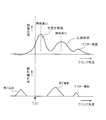
- FIG. 8 and FIG. 9 show examples of combustion modes (“diffusion combustion” and “union combustion”) when fuel injection into the combustion chamber of a diesel engine is divided into two injections of the first injection and the second injection. Shown in
- the combustion mode shown in FIG. 8 is an example of “diffusion combustion”. Most of the combustion by the first injection is premixed combustion, preheating is performed by the combustion by the first injection, and the combustion by the second injection is diffusion combustion. It is said. By making the entire combustion “diffusion combustion” in this way, combustion in the combustion chamber 3 can be performed stably, and a sufficient output can be obtained particularly during high load operation where stabilization of combustion is required. be able to.
- the combustion mode shown in FIG. 9 is an example of “combined combustion”, and by increasing the fuel injection amount of the first injection and performing the second injection close to the first injection, the spray interference cooling effect is achieved. Combustion with maximum utilization.
- combined combustion by using premixed combustion in which the ignition delay of combustion by the first injection is increased, both the amount of smoke generated and the amount of NOx generated can be suppressed, and deterioration of fuel consumption can be suppressed. it can.
- the “combined combustion” as shown in FIG. 9 can shorten the combustion period and is efficient, and the smoke generation amount and NOX generation are caused by the effect of reducing the in-cylinder oxygen concentration by increasing the premixed combustion component.
- the amount can be controlled.
- the ignition delay of the fuel by the first injection induces the ignition delay of the combustion by the second injection, and the entire combustion becomes the ignition delay, so that the fuel has low robustness (stability).
- the in-cylinder pressure decreases due to a delay in supercharging by the supercharging device during transient operation or the oxygen concentration in the cylinder decreases due to a delay in the EGR amount reduction operation, etc.
- the combustion center of gravity is greatly retarded.
- HC hydrocarbon
- misfire may occur.
- even when a low cetane number fuel is used the same problem occurs because the ignition delay of premixed combustion becomes large.
- the combustion by the first injection is premixed combustion
- the combustion by the second injection is diffusion combustion
- the premixed combustion and diffusion combustion are separated from each other (separated combustion).
- the advantages of the premixed combustion and the diffusion combustion are that the exhaust emission is improved and the combustion stability is improved. Specific control examples ([Embodiment 1] and [Embodiment 2]) will be described below.
- this premixing is performed while suppressing both the amount of smoke generated and the amount of NOx generated by the premixed combustion.
- Combustion stability can be ensured by diffusion combustion separated from combustion.
- the ignition delay of the previous premixed combustion does not affect the subsequent diffusion combustion, so during transient operation of the internal combustion engine or when using low cetane number fuel, etc. Even if the ignition delay of premixed combustion becomes large, the stability of combustion can be ensured.
- the second injection is executed in the state where the preheating in the combustion chamber 3 is sufficiently performed by the premixed combustion in the first injection.
- the fuel injected into the combustion chamber 3 is immediately exposed to a temperature environment equal to or higher than the auto-ignition temperature, and pyrolysis proceeds. After the injection, combustion starts immediately.
- fuel ignition delays in diesel engines include physical delays and chemical delays.
- the physical delay is the time required for evaporation / mixing of the fuel droplets and depends on the gas temperature of the combustion field.
- the chemical delay is the time required for chemical bonding / decomposition of fuel vapor and oxidation heat generation.
- the physical delay can be minimized, and as a result, the ignition delay is also minimized. Will be. Therefore, as a combustion mode of the fuel injected by the second injection, premixed combustion is hardly performed, and most of it is diffusion combustion.
- the ignition timing in diffusion combustion by adjusting the injection timing and the injection amount of the second injection, the ignition timing in diffusion combustion, the rate of change of the heat generation rate (the gradient of the heat generation rate waveform), the peak of the heat generation rate, and the combustion center of gravity are reached. It becomes possible to control the timing together.
- the generation amount can be suppressed.
- the injection timing of the second injection for diffusion combustion is retarded, the combustion space expands and the oxygen concentration decreases, so smoke tends to be generated.
- the generation of smoke is suppressed by adjusting the fuel injection amount of the second injection in accordance with the retardation of the injection timing of the second injection for diffusion combustion (the retardation of diffusion combustion). To do. The specific method will be described later.
- the total fuel injection amount for split injection (necessary for obtaining the required total torque) according to the operating conditions such as engine speed, accelerator operation amount, cooling water temperature, intake air temperature, and environmental conditions.
- the total fuel injection amount is obtained with reference to a known map or the like.
- an injection timing at which the combustion center of gravity of diffusion combustion by the second injection becomes, for example, BTDC (after the top dead center of the piston 13) 20 ° CA (crank angle) is set as a retard guard value.
- the delay angle of the second injection may be limited by setting the injection timing such that the combustion center of gravity of the fuel by the second injection becomes, for example, BTDC 15 ° CA.
- the upper limit fuel amount map used for this processing uses the retardation value of the injection timing of the second injection as a parameter, and previously sets the upper limit value of the amount of fuel that does not cause smoke in diffusion combustion (the amount of fuel combustible in retarded diffusion combustion).
- a value (upper limit fuel amount) that has been acquired by experiments / simulations, etc., and is adapted based on the result is mapped, and stored in the ROM 102 of the ECU 100, for example.
- the upper limit fuel amount in the diffusion combustion is set to be smaller as the retardation value of the injection timing of the second injection is larger.
- the calculated fuel injection amount of the first injection is larger than the upper limit amount. If the fuel injection amount of the first injection is less than or equal to the upper limit amount, the value calculated in the above process is set to the first value.
- the fuel injection amount is one injection.
- the calculated fuel injection amount of the first injection is larger than the upper limit amount, the amount exceeding the upper limit amount (the surplus fuel amount) is, for example, after injection after the second injection as shown in FIG.
- the generated torque is secured by injecting with Note that the upper limit amount of the fuel injection amount of the first injection is a value (upper limit amount) adapted in consideration of the limit value (allowable value) of the combustion noise generated according to the fuel injection amount of the first injection. .
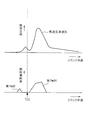
- [S15] Based on the injection timing of the second injection (retarded value of the injection start timing), the fuel injection amount, and the fuel injection amount of the first injection obtained in the processes of [S11] to [S14], for example, As shown in FIG. 4, the combustion gravity center of premixed combustion and the combustion gravity center of diffusion combustion are separated, and the minimum value Lq of the heat release rate between these two combustion gravity centers is smaller than 10 [J / ° CA]. Thus, the injection timing (injection start timing) of the first injection is determined.
- the injection timing of the second injection (retarded value of the injection start timing), the fuel injection amount, and the fuel injection amount of the first injection obtained in the above-described processes [S11] to [S14]. Based on the map below, the injection start timing of the first injection is calculated. Further, based on the fuel injection amount of the first injection and the injection characteristics (injection amount per unit time, etc.) of the injector 23, the injection period (injection start timing to injection end timing) of the first injection shown in FIG. 4 is determined. To do.
- the injection start timing (calculated value) of the first injection is on the retard side or the advance side with respect to the following advance guard value, and the injection start timing of the first injection is advanced. If it is the retard side from the guard value, the fuel injection pattern as shown in FIG. 4 is determined using the injection start timing and the injection end timing of the first injection calculated in the above-described process as they are.
- the injection timing (calculated value) of the first injection is on the retard side with respect to the advance guard value
- the injection timing of the first injection is increased in order to increase the premixing degree of the premixed combustion by the first injection. May be advanced to the advance guard value.
- the injection timing of the first injection is more advanced than the advance guard value
- the injection timing of the first injection is limited to the advance guard value.
- the reduction correction amount (excess fuel amount) of the first injection is, for example, after the second injection as shown in FIG. The generated torque is secured by injecting after-injection.
- the injection start timing setting map used for the process of [S15] uses the injection start timing / fuel injection amount of the second injection and the fuel injection amount of the first injection as parameters, and premixed combustion and diffusion combustion shown in FIG.
- the injection start timing of the first injection so that the minimum value Lq of the heat generation rate between the combustion center of gravity and the combustion center becomes smaller than 10 [J / ° CA] is obtained in advance by experiments, simulations, etc.
- a value (injection start time of the first injection) adapted to the base is mapped and stored in the ROM 102 of the ECU 100, for example.
- the advance angle guard value of the first injection is obtained with reference to the map shown in FIG. 5 based on the engine speed calculated from the detected value of the crank position sensor 40.
- the map of FIG. 5 is a map in which values obtained by empirically adapting the advance angle guard value in advance through experiments and simulations using the engine speed as a parameter, and are stored in the ROM 102 of the ECU 100, for example.
- the combustion center of gravity of the premixed combustion and the combustion center of gravity of the diffusion combustion are separated, and these Since the fuel injection pattern is adjusted so that the minimum value of the heat generation rate between the two combustion centroids is smaller than the predetermined value, it is possible to separate the premixed combustion and the diffusion combustion into separate combustion. it can. Thereby, it becomes possible to utilize the respective advantages of premixed combustion and diffusion combustion, and it is possible to improve exhaust emission and improve the stability of combustion.
- the stability of combustion can be ensured by diffusion combustion separated from this premixed combustion while suppressing both the amount of smoke generated and the amount of NOx generated by premixed combustion. Moreover, by separating premixed combustion and diffusion combustion, the ignition delay of the previous premixed combustion does not affect the subsequent diffusion combustion, so during transient operation of the internal combustion engine or when using low cetane number fuel, etc. Even if the ignition delay of premixed combustion becomes large, the stability of combustion can be ensured.
- the injection timing of the second injection is retarded (diffuse combustion is retarded) according to the required NOx amount, and the fuel injection amount of the second injection can be combusted by retarded diffusion combustion. Therefore, the amount of NOx can be regulated to a required value while suppressing the generation of smoke.
- the first injection may be divided injection obtained by dividing the injection into a plurality of times.
- the first injection is divided injection in this way, unburned HC due to overdiffusion can be suppressed.
- the interval T between the injection end timing of the first injection for premixed combustion and the injection start timing of the second injection for diffusion combustion is an injection of the first injection.
- the premixed combustion by the first injection is adjusted by adjusting the fuel injection pattern (fuel injection form) so as to be equal to or longer than the total period of the period (injection start to injection end) and the ignition delay period of the combustion by the first injection.
- the combustion by the second injection are made sparse (the combustion by the first injection does not affect the combustion by the second injection).
- the fuel injection period into the combustion chamber is proportional to the combustion period of “combustion” generated by the fuel injection, and therefore, during the first injection period (combustion period),
- the ignition delay of the combustion by the first injection becomes large.
- the ignition delay of the first injection can be prevented from affecting the combustion (diffusion combustion) by the second injection.
- the characteristics of diffusion combustion by the second injection ignition timing, rate of change of heat generation rate (gradient of the heat generation rate waveform), peak of heat generation rate, timing of reaching the combustion center of gravity, and diffusion About the retarding angle of combustion) and the like, it can be said to be the same as that described in the above [Embodiment 1], and therefore detailed description thereof is omitted.
- FIG. 6 shows a specific control procedure in the case where fuel injection from the injector 23 is executed by adjusting the fuel injection pattern of split injection (interval T between the first injection and the second injection) as described above. I will explain. Note that the processing described below can be executed by the ECU 100.
- the total fuel injection amount for split injection (necessary for obtaining the required total torque) according to the operating conditions such as engine speed, accelerator operation amount, cooling water temperature, intake air temperature, and environmental conditions.
- the total fuel injection amount is obtained with reference to a known map or the like.
- the calculated fuel injection amount of the first injection is larger than the upper limit amount. If the fuel injection amount of the first injection is less than or equal to the upper limit amount, the value calculated in the above process is set to the first value.
- the fuel injection amount is one injection.
- the calculated fuel injection amount of the first injection is larger than the upper limit amount, the amount exceeding the upper limit amount (the surplus fuel amount) is, for example, after injection after the second injection as shown in FIG.
- the generated torque is secured by injecting with Note that the upper limit amount of the fuel injection amount of the first injection is a value (upper limit amount) adapted in consideration of the limit value (allowable value) of the combustion noise generated according to the fuel injection amount of the first injection. .
- the map for determining the ignition delay period of the first injection is, for example, the ignition of the first injection using the in-cylinder gas state (eg, temperature, pressure, oxygen concentration) before ignition and the fuel injection amount of the first injection as parameters.
- a value obtained by adapting the delay period by experiment / simulation or the like is mapped and stored in the ROM 102 of the ECU 100, for example.
- the interval T between the first injection and the second injection may be set longer than [the injection period of the first injection + the ignition delay period], but the heat generation rate waveform as shown in FIG. If the interval T between the first injection and the second injection is too long and the combustion center of gravity of the premixed combustion and the combustion center of gravity of the diffusion combustion are too far apart, the premixed combustion by the first injection causes the combustion chamber to Is not sufficiently preheated, and there is a concern about the delayed ignition of diffusion combustion due to the second injection. In view of this point, the first injection and the above-mentioned first injection are performed so that the ignition timing of diffusion combustion becomes an appropriate time. The upper limit value of the interval T between the second injection is limited.
- the injection start timing (calculated value) of the first injection is on the retard side or the advance side with respect to the advance guard value (see FIG. 5), and the injection of the first injection If the start timing is retarded from the advance guard value, the fuel injection pattern as shown in FIG. 6 is used using the injection start timing and injection end timing of the first injection calculated in the above-described process as they are. decide.
- the injection timing (calculated value) of the first injection is on the retard side with respect to the advance guard value, the injection of the first injection is performed in order to increase the premixing degree of the premixed combustion by the first injection. The time may be advanced to the advance guard value.
- the injection start timing (calculated value) of the first injection is on the advance side of the advance guard value
- the injection timing of the first injection is limited to the advance guard value.
- the reduction correction amount (excess fuel amount) of the first injection is, for example, after the second injection as shown in FIG.
- the generated torque is secured by injecting after-injection.
- the interval T between the first injection and the second injection is set to the injection of the first injection. Since the fuel injection pattern is controlled so as to be the total period of the period and the ignition delay period of the combustion by the first injection, it is possible to perform the separated combustion in which the premixed combustion and the diffusion combustion are separated. Thereby, it becomes possible to utilize the respective advantages of premixed combustion and diffusion combustion, and it is possible to improve exhaust emission and improve the stability of combustion. That is, as described above, the stability of combustion can be ensured by diffusion combustion separated from this premixed combustion while suppressing both the amount of smoke generated and the amount of NOx generated by premixed combustion.
- the ignition delay of the previous premixed combustion does not affect the subsequent diffusion combustion, so during transient operation of the internal combustion engine or when using low cetane number fuel, etc. Even if the ignition delay of premixed combustion becomes large, the stability of combustion can be ensured.
- the injection timing of the second injection is retarded (diffuse combustion is retarded) according to the required NOx amount, and the fuel injection amount of the second injection can be combusted by retarded diffusion combustion. Therefore, the amount of NOx can be regulated to a required value while suppressing the generation of smoke.
- the first injection may be divided injection obtained by dividing the injection into a plurality of times.
- the first injection is divided injection in this way, unburned HC due to overdiffusion can be suppressed.
- the manipulator 77 is provided with the NSR catalyst 75 and the DPNR catalyst 76, but may be provided with the NSR catalyst 75 and a DPF (Diesel Particle Filter).
- DPF Diesel Particle Filter
- the present invention can be used for combustion control for improving exhaust emission and stability of combustion in a common rail in-cylinder direct injection multi-cylinder diesel engine mounted on an automobile.
Abstract
Description
上記の目的を達成するために講じられた本発明の解決原理は、燃焼室内における燃焼形態として予混合燃焼及び拡散燃焼のそれぞれの優位点を利用できるように、これら予混合燃焼の重心と拡散燃焼の重心とをずらして、それら予混合燃焼と拡散燃焼とを分離させることにより、排気エミッションの改善及び燃焼の安定性を図る点に特徴がある。 -Solution principle of the problem- The solution principle of the present invention taken to achieve the above object is that the premixed combustion and the diffusion combustion can be used as the combustion form in the combustion chamber so that the premixed combustion and the diffusion combustion can be used. The center of gravity of combustion and the center of gravity of diffusion combustion are shifted so that the premixed combustion and diffusion combustion are separated to improve exhaust emission and to stabilize combustion.
本発明は、燃料噴射弁から燃焼室内に噴射された燃料が、「予混合燃焼」及びこの「予混合燃焼」の後に開始される「拡散燃焼」により燃焼室内で燃焼する圧縮自着火式の内燃機関の燃焼制御装置を前提しており、このような内燃機関の燃焼制御装置において、前記燃焼室内での燃焼形態が、予混合燃焼の燃焼重心と拡散燃焼の燃焼重心とが分離され、かつ、それら2つの燃焼重心間における熱発生率の最小値が所定値よりも小さい燃焼形態となるように、前記燃料噴射弁の燃料噴射形態(燃料噴射パターン)を調整する噴射制御手段を備えていることを技術的特徴としている。 -Solution-
The present invention relates to a compression self-ignition internal combustion in which fuel injected from a fuel injection valve is combusted in a combustion chamber by “premixed combustion” and “diffusion combustion” started after this “premixed combustion”. Presupposing an engine combustion control device, in such a combustion control device for an internal combustion engine, the combustion mode in the combustion chamber is such that the combustion center of gravity of premixed combustion and the combustion center of gravity of diffusion combustion are separated, and Injecting control means for adjusting the fuel injection mode (fuel injection pattern) of the fuel injection valve so that the minimum value of the heat generation rate between the two combustion centroids becomes a combustion mode smaller than a predetermined value. Is a technical feature.
この場合、第1噴射の噴射時期の進角量に対する進角ガード値は、機関回転数(エンジン回転数)に応じて可変に設定するようにしてもよい。 In the present invention, (b1) injection of the first injection in order to separate the premixed combustion by the first injection and the diffusion combustion by the second injection (in order to expand the interval between the first injection and the second injection). When it is necessary to advance the timing greatly with respect to the piston compression top dead center (TDC), or (b2) advance the first injection in order to increase the premixed combustion degree of the premixed combustion by the first injection. In this case, if the injection timing of the first injection is advanced too much, unburned HC (hydrocarbon) increases. Therefore, in order to suppress this, the advance amount of the first injection is limited by a guard value. There is a need. The advance guard value is set in consideration of the amount of unburned HC (hydrocarbon) generated.
In this case, the advance guard value for the advance amount of the injection timing of the first injection may be variably set according to the engine speed (engine speed).
まず、本発明を適用するディーゼルエンジン(以下、単にエンジンという)の一例について説明する。図1はエンジン1及びその制御系統の概略構成図である。また図2は、ディーゼルエンジンの燃焼室3及びその周辺部を示す断面図である。 -Engine configuration-
First, an example of a diesel engine (hereinafter simply referred to as an engine) to which the present invention is applied will be described. FIG. 1 is a schematic configuration diagram of the
エンジン1の各部位には、各種センサが取り付けられており、それぞれの部位の環境条件や、エンジン1の運転状態に関する信号を出力する。 -Sensors-
Various sensors are attached to each part of the
ECU100は、図3に示すように、CPU101、ROM102、RAM103及びバックアップRAM104などを備えている。ROM102は、各種制御プログラムや、それら各種制御プログラムを実行する際に参照されるマップ等が記憶されている。CPU101は、ROM102に記憶された各種制御プログラムやマップに基づいて各種の演算処理を実行する。RAM103は、CPU101での演算結果や各センサから入力されたデータ等を一時的に記憶するメモリである。バックアップRAM104は、例えばエンジン1の停止時にその保存すべきデータ等を記憶する不揮発性のメモリである。 -ECU-
As shown in FIG. 3, the
上記分割噴射を実行する際の燃料噴射圧はコモンレール22の内圧により決定される。このコモンレール内圧として、一般に、コモンレール22からインジェクタ23へ供給される燃料圧力の目標値つまり目標レール圧は、エンジン負荷(機関負荷)が高くなるほど、及び、エンジン回転数(機関回転数)が高くなるほど高いものとされる。すなわち、エンジン負荷が高い場合には燃焼室3内に吸入される空気量が多いため、インジェクタ23から燃焼室3内に向けて多量の燃料を噴射しなければならず、よってインジェクタ23からの噴射圧力を高いものとする必要がある。また、エンジン回転数が高い場合には噴射可能な期間が短いため、単位時間当たりに噴射される燃料量を多くしなければならず、よってインジェクタ23からの噴射圧力を高いものとする必要がある。このように、目標レール圧は一般にエンジン負荷及びエンジン回転数に基づいて設定される。なお、この目標レール圧は例えば上記ROM102に記憶された燃圧設定マップに従って設定される。つまり、この燃圧設定マップに従って燃料圧力を決定することで、インジェクタ23の開弁期間(噴射率波形)が制御され、その開弁期間中における燃料噴射量を規定することが可能になる。なお、本実施形態では、エンジン負荷等に応じて燃料圧力が30MPa~200MPaの間で調整されるようになっている。 -Fuel injection pressure-
The fuel injection pressure when executing the divided injection is determined by the internal pressure of the
ここで、燃料噴射量と貫徹力との関係について説明する。上記インジェクタ23では、噴射指令信号を受けて燃料噴射が開始されると、噴射孔を閉塞しているニードルが噴射孔から後退していくことで噴射孔の開口面積を次第に増大させていく。そして、ニードルが最後退位置まで移動すると噴射孔の開口面積は最大となる。ところが、このニードルが最後退位置に達するまでに噴射指令信号が解除されると(閉弁指令を受けると)、後退移動している途中でニードルは閉弁方向に向かって前進することになる。つまり、この場合、噴射孔の開口面積は最大となることなく燃料噴射を終了することになる。このため、噴射期間が長く設定されるほど噴射孔の開口面積としては大きく得られることになる。 -About penetration-
Here, the relationship between the fuel injection amount and the penetration force will be described. In the
次に、本実施形態で実行する分割噴射について説明する。 -Split injection-
Next, the divided injection executed in the present embodiment will be described.
この実施形態では、図4に示すように、予混合燃焼の燃焼重心と拡散燃焼の燃焼重心とを分離し、それら2つの燃焼重心間における熱発生率の最小値(熱発生率波形の最小ピーク)Lqを所定値(具体的には10[J/°CA])よりも小さくなるように制御して、これら予混合燃焼と拡散燃焼との重畳熱発生率を制限することにより、予混合燃焼と拡散燃焼とを分離する点に特徴がある。 [Embodiment 1]
In this embodiment, as shown in FIG. 4, the combustion centroid of premixed combustion and the combustion centroid of diffusion combustion are separated, and the minimum value of the heat generation rate between these two combustion centroids (the minimum peak of the heat generation rate waveform). ) By controlling Lq to be smaller than a predetermined value (specifically, 10 [J / ° CA]) and limiting the superimposed heat generation rate of these premixed combustion and diffusion combustion, premixed combustion It is characterized in that it separates from diffusion combustion.
次に、上述の如く分割噴射の燃料噴射パターン(予混合用の第1噴射の噴射時期・燃料噴射量、及び、拡散燃焼用の第2噴射の噴射時期・燃料噴射量)を調整してインジェクタ23からの燃料噴射を実行する場合の具体的な制御手順について、図4を参照して説明する。なお、以下に説明する処理はECU100において実行される。 -Specific control procedure-
Next, as described above, the fuel injection pattern of the split injection (the injection timing / fuel injection amount of the first injection for premixing and the injection timing / fuel injection amount of the second injection for diffusion combustion) is adjusted, and the injector A specific control procedure when the fuel injection from 23 is executed will be described with reference to FIG. In addition, the process demonstrated below is performed in ECU100.
上記[S15]の処理に用いる噴射開始時期設定マップは、第2噴射の噴射開始時期・燃料噴射量、及び、第1噴射の燃料噴射量をパラメータとして、図4に示す予混合燃焼と拡散燃焼との燃焼重心間における熱発生率の最小値Lqが10[J/°CA]よりも小さくなるような第1噴射の噴射開始時期を、予め実験・シミュレーション等によって取得しておき、その結果を基に適合した値(第1噴射の噴射開始時期)をマップ化したものであって、例えばECU100のROM102に格納されている。 (Injection timing setting map for the first injection)
The injection start timing setting map used for the process of [S15] uses the injection start timing / fuel injection amount of the second injection and the fuel injection amount of the first injection as parameters, and premixed combustion and diffusion combustion shown in FIG. The injection start timing of the first injection so that the minimum value Lq of the heat generation rate between the combustion center of gravity and the combustion center becomes smaller than 10 [J / ° CA] is obtained in advance by experiments, simulations, etc. A value (injection start time of the first injection) adapted to the base is mapped and stored in the
第1噴射の進角ガード値については、クランクポジションセンサ40の検出値から算出されるエンジン回転数に基づいて図5に示すマップを参照して求める。図5のマップは、エンジン回転数をパラメータとして、予め実験・シミュレーション等によって進角ガード値を経験的に適合した値をマップ化したものであって、例えばECU100のROM102内に格納されている。 (Advance guard value)
The advance angle guard value of the first injection is obtained with reference to the map shown in FIG. 5 based on the engine speed calculated from the detected value of the
この実施形態では、図6に示すように、予混合燃焼用の第1噴射の噴射終了時期と、拡散燃焼用の第2噴射の噴射開始時期との間のインターバルTが、第1噴射の噴射期間(噴射開始~噴射終了)と、当該第1噴射による燃焼の着火遅れ期間との合計期間以上となるように燃料噴射パターン(燃料噴射形態)を調整することで、第1噴射による予混合燃焼と第2噴射による燃焼との燃焼関係を疎にしている(第1噴射による燃焼が第2噴射による燃焼に影響しなようにしている)。 [Embodiment 2]
In this embodiment, as shown in FIG. 6, the interval T between the injection end timing of the first injection for premixed combustion and the injection start timing of the second injection for diffusion combustion is an injection of the first injection. The premixed combustion by the first injection is adjusted by adjusting the fuel injection pattern (fuel injection form) so as to be equal to or longer than the total period of the period (injection start to injection end) and the ignition delay period of the combustion by the first injection. And the combustion by the second injection are made sparse (the combustion by the first injection does not affect the combustion by the second injection).
上述の如く分割噴射の燃料噴射パターン(第1噴射と第2噴射との間のインターバルT)を調整してインジェクタ23からの燃料噴射を実行する場合の具体的な制御手順について図6を参照して説明する。なお、以下に説明する処理はECU100において実行することが可能である。 -Specific control procedure-
FIG. 6 shows a specific control procedure in the case where fuel injection from the
以上の例では、コモンレール式筒内直噴型多気筒(4気筒)ディーゼルエンジンに本発明を適用した場合について説明した。本発明はこれに限らず、例えば6気筒ディーゼルエンジンなど他の任意の気筒数のディーゼルエンジンにも適用可能である。また、本発明が適用可能なエンジンは、自動車用のエンジンに限るものではない。 -Other embodiments-
In the above example, the case where the present invention is applied to a common rail in-cylinder direct injection multi-cylinder (four-cylinder) diesel engine has been described. The present invention is not limited to this, and can be applied to a diesel engine having any number of cylinders such as a six-cylinder diesel engine. The engine to which the present invention is applicable is not limited to an automobile engine.
3 燃焼室
23 インジェクタ(燃料噴射弁)
40 クランクポジションセンサ
47 アクセル開度センサ
100 ECU 1 engine (internal combustion engine)
3
40
Claims (15)
- 燃料噴射弁から燃焼室内に噴射された燃料が、「予混合燃焼」及びこの「予混合燃焼」の後に開始される「拡散燃焼」により燃焼室内で燃焼する圧縮自着火式の内燃機関の燃焼制御装置において、
前記燃焼室内での燃焼形態が、予混合燃焼の燃焼重心と拡散燃焼の燃焼重心とが分離され、かつ、それら2つの燃焼重心間における熱発生率の最小値が所定値よりも小さい燃焼形態となるように、前記燃料噴射弁の燃料噴射形態を調整する噴射制御手段を備えていることを特徴とする内燃機関の燃焼制御装置。 Combustion control of a compression auto-ignition internal combustion engine in which fuel injected from a fuel injection valve is combusted in the combustion chamber by “premixed combustion” and “diffusion combustion” started after this “premixed combustion” In the device
The combustion mode in the combustion chamber is a combustion mode in which the combustion gravity center of premixed combustion and the combustion gravity center of diffusion combustion are separated, and the minimum value of the heat generation rate between the two combustion gravity centers is smaller than a predetermined value. Thus, the combustion control device for an internal combustion engine is characterized by comprising injection control means for adjusting the fuel injection mode of the fuel injection valve. - 請求項1記載の内燃機関の燃焼制御装置において、
前記燃料噴射弁は、上記燃焼室内での燃焼として主に「予混合燃焼」を行わせるための第1噴射と、上記燃焼室内での燃焼として主に「拡散燃焼」を行わせるための第2噴射とを個別に実行可能となっており、これら第1噴射及び第2噴射の燃料噴射形態を調整することにより、予混合燃焼の燃焼重心と拡散燃焼の燃焼重心とが分離され、かつ、それら2つの燃焼重心間における熱発生率の最小値が所定値よりも小さい燃焼形態に制御することを特徴とする内燃機関の燃焼制御装置。 The combustion control apparatus for an internal combustion engine according to claim 1,
The fuel injection valve has a first injection for mainly performing “premixed combustion” as combustion in the combustion chamber, and a second for mainly performing “diffusion combustion” as combustion in the combustion chamber. The fuel gravity center of the premixed combustion and the combustion gravity center of the diffusion combustion are separated by adjusting the fuel injection modes of the first injection and the second injection. A combustion control apparatus for an internal combustion engine, characterized in that the minimum value of the heat generation rate between two combustion centroids is controlled to a combustion mode smaller than a predetermined value. - 請求項2記載の内燃機関の燃焼制御装置において、
要求NOx量に応じて、前記拡散燃焼用の第2噴射の噴射時期をピストン圧縮上死点に対して遅角して拡散燃焼を遅角するとともに、その遅角拡散燃焼の燃焼重心と予混合燃焼の燃焼重心との間の熱発生率の最小値が所定値よりも小さくなるように、前記予混合燃焼用の第1噴射の噴射時期を調整することを特徴とする内燃機関の燃焼制御装置。 The combustion control apparatus for an internal combustion engine according to claim 2,
In accordance with the required amount of NOx, the injection timing of the second injection for diffusion combustion is retarded with respect to the piston compression top dead center to retard the diffusion combustion, and the combustion center of gravity of the retarded diffusion combustion and the premixing A combustion control apparatus for an internal combustion engine, characterized in that the injection timing of the first injection for premixed combustion is adjusted so that the minimum value of the heat generation rate between the center of combustion and the combustion center of gravity is smaller than a predetermined value. . - 請求項3記載の内燃機関の燃焼制御装置において、
要求NOx量に応じて拡散燃焼を遅角するにあたり、その遅角拡散燃焼で燃焼可能な燃料量を前記第2噴射の燃料噴射量とし、その第2噴射の燃料噴射量と要求総燃料噴射量とに基づいて前記第1噴射の燃料噴射量を決定することを特徴とする内燃機関の燃焼制御装置。 The combustion control apparatus for an internal combustion engine according to claim 3,
When retarding diffusion combustion according to the required NOx amount, the amount of fuel combustible by the retarded diffusion combustion is set as the fuel injection amount of the second injection, and the fuel injection amount of the second injection and the required total fuel injection amount And determining the fuel injection amount of the first injection based on the following. - 請求項4記載の内燃機関の燃焼制御装置において、
前記第2噴射の燃料噴射量と要求総燃料噴射量とに基づいて決定される第1噴射の燃料噴射量が所定の上限量よりも多い場合、その余剰燃料量分については前記第2噴射後に噴射されるように前記燃料噴射弁の燃料噴射形態を調整することを特徴とする内燃機関の燃焼制御装置。 The combustion control device for an internal combustion engine according to claim 4,
When the fuel injection amount of the first injection determined based on the fuel injection amount of the second injection and the required total fuel injection amount is greater than a predetermined upper limit amount, the surplus fuel amount is determined after the second injection. A combustion control apparatus for an internal combustion engine, wherein the fuel injection mode of the fuel injection valve is adjusted so that the fuel is injected. - 請求項2~5のいずれか1つに記載の内燃機関の燃焼制御装置において、
前記第1噴射の噴射時期をピストン圧縮上死点に対して進角させる際に、その第1噴射の噴射時期の進角量をガード値によって制限することを特徴とする内燃機関の燃焼制御装置。 The internal combustion engine combustion control apparatus according to any one of claims 2 to 5,
A combustion control apparatus for an internal combustion engine, wherein when the injection timing of the first injection is advanced with respect to the piston compression top dead center, the advance amount of the injection timing of the first injection is limited by a guard value. . - 請求項6記載の内燃機関の燃焼制御装置において、
前記第1噴射の進角量を制限するガード値は未燃炭化水素の発生量を考慮して設定されることを特徴とする内燃機関の燃焼制御装置。 The combustion control device for an internal combustion engine according to claim 6,
A combustion control device for an internal combustion engine, wherein a guard value for limiting an advance amount of the first injection is set in consideration of a generation amount of unburned hydrocarbons. - 請求項2~7のいずれか1つに記載の内燃機関の燃焼制御装置において、
前記第1噴射による燃料噴射が複数回に分割して実行されることを特徴とする内燃機関の燃焼制御装置。 The combustion control device for an internal combustion engine according to any one of claims 2 to 7,
A combustion control apparatus for an internal combustion engine, characterized in that fuel injection by the first injection is performed in a plurality of times. - 燃料噴射弁から燃焼室内に噴射された燃料が、「予混合燃焼」及びこの「予混合燃焼」の後に開始される「拡散燃焼」により燃焼室内で燃焼する圧縮自着火式の内燃機関の燃焼制御装置において、
前記燃料噴射弁は、燃料噴射弁による燃料噴射形態を、主に「予混合燃焼」を行わせるための第1噴射と、主に「拡散燃焼」を行わせるための第2噴射とを個別に実行可能となっており、
前記予混合燃焼用の第1噴射の噴射終了時期と、前記拡散燃焼用の第2噴射の噴射開始時期との間のインターバルを、前記第1噴射の噴射期間とこの第1噴射による燃焼の着火遅れ期間との合計期間以上に調整する噴射制御手段を備えていることを特徴とする内燃機関の燃焼制御装置。 Combustion control of a compression auto-ignition internal combustion engine in which fuel injected from a fuel injection valve is combusted in the combustion chamber by “premixed combustion” and “diffusion combustion” started after this “premixed combustion” In the device
In the fuel injection valve, the fuel injection mode by the fuel injection valve is divided into a first injection for mainly performing “premixed combustion” and a second injection for mainly performing “diffusion combustion”. Is executable,
An interval between the injection end timing of the first injection for premixed combustion and the injection start timing of the second injection for diffusion combustion is defined as an injection period of the first injection and ignition of combustion by the first injection. A combustion control apparatus for an internal combustion engine, comprising an injection control means for adjusting the total period of the delay period or more. - 請求項9記載の内燃機関の燃焼制御装置において、
要求NOx量に応じて、前記拡散燃焼用の第2噴射の噴射時期をピストン圧縮上死点に対して遅角して拡散燃焼を遅角するとともに、その噴射時期を遅角した第2噴射と前記第1噴射との間のインターバルが前記合計期間以上となるように、前記予混合燃焼用の第1噴射の噴射時期を調整することを特徴とする内燃機関の燃焼制御装置。 The combustion control apparatus for an internal combustion engine according to claim 9,
Depending on the required NOx amount, the second injection for diffusion combustion is retarded with respect to the piston compression top dead center to retard diffusion combustion, and the second injection is retarded. A combustion control apparatus for an internal combustion engine, wherein an injection timing of the first injection for premixed combustion is adjusted so that an interval between the first injection and the total injection period is equal to or longer than the total period. - 請求項10記載の内燃機関の燃焼制御装置において、
要求NOx量に応じて拡散燃焼を遅角するにあたり、その遅角拡散燃焼で燃焼可能な燃料量を前記第2噴射の燃料噴射量とし、その第2噴射の燃料噴射量と要求総燃料噴射量とに基づいて前記第1噴射の燃料噴射量を決定することを特徴とする内燃機関の燃焼制御装置。 The combustion control device for an internal combustion engine according to claim 10,
When retarding diffusion combustion according to the required NOx amount, the amount of fuel combustible by the retarded diffusion combustion is set as the fuel injection amount of the second injection, and the fuel injection amount of the second injection and the required total fuel injection amount And determining the fuel injection amount of the first injection based on the following. - 請求項11記載の内燃機関の燃焼制御装置において、
前記第2噴射の燃料噴射量と要求総燃料噴射量とに基づいて決定される第1噴射の燃料噴射量が所定の上限量よりも多い場合、その余剰燃料量分については前記第2噴射後に噴射されるように前記燃料噴射弁の燃料噴射形態を調整することを特徴とする内燃機関の燃焼制御装置。 The combustion control device for an internal combustion engine according to claim 11,
When the fuel injection amount of the first injection determined based on the fuel injection amount of the second injection and the required total fuel injection amount is greater than a predetermined upper limit amount, the surplus fuel amount is determined after the second injection. A combustion control apparatus for an internal combustion engine, wherein the fuel injection mode of the fuel injection valve is adjusted so that the fuel is injected. - 請求項9~12のいずれか1つに記載の内燃機関の燃焼制御装置において、
前記第1噴射の噴射時期をピストン圧縮上死点に対して進角させる際に、その第1噴射の噴射時期の進角量をガード値によって制限することを特徴とする内燃機関の燃焼制御装置。 The combustion control device for an internal combustion engine according to any one of claims 9 to 12,
A combustion control apparatus for an internal combustion engine, wherein when the injection timing of the first injection is advanced with respect to the piston compression top dead center, the advance amount of the injection timing of the first injection is limited by a guard value. . - 請求項13記載の内燃機関の燃焼制御装置において、
前記第1噴射の進角量を制限するガード値は未燃炭化水素の発生量を考慮して設定されることを特徴とする内燃機関の燃焼制御装置。 The combustion control device for an internal combustion engine according to claim 13,
A combustion control device for an internal combustion engine, wherein a guard value for limiting an advance amount of the first injection is set in consideration of a generation amount of unburned hydrocarbons. - 請求項9~14のいずれか1つに記載の内燃機関の燃焼制御装置において、
前記第1噴射による燃料噴射が複数回に分割して実行されることを特徴とする内燃機関の燃焼制御装置。 The combustion control device for an internal combustion engine according to any one of claims 9 to 14,
A combustion control apparatus for an internal combustion engine, characterized in that fuel injection by the first injection is performed in a plurality of times.
Priority Applications (5)
| Application Number | Priority Date | Filing Date | Title |
|---|---|---|---|
| PCT/JP2010/055399 WO2011118031A1 (en) | 2010-03-26 | 2010-03-26 | Combustion control device for internal combustion engine |
| CN201080065761.5A CN102822485B (en) | 2010-03-26 | 2010-03-26 | Combustion control device for internal combustion engine |
| US13/637,563 US20130024097A1 (en) | 2010-03-26 | 2010-03-26 | Combustion control apparatus for internal combustion engine |
| EP10848424A EP2551499A1 (en) | 2010-03-26 | 2010-03-26 | Combustion control device for internal combustion engine |
| JP2012506742A JP5278596B2 (en) | 2010-03-26 | 2010-03-26 | Combustion control device for internal combustion engine |
Applications Claiming Priority (1)
| Application Number | Priority Date | Filing Date | Title |
|---|---|---|---|
| PCT/JP2010/055399 WO2011118031A1 (en) | 2010-03-26 | 2010-03-26 | Combustion control device for internal combustion engine |
Publications (1)
| Publication Number | Publication Date |
|---|---|
| WO2011118031A1 true WO2011118031A1 (en) | 2011-09-29 |
Family
ID=44672620
Family Applications (1)
| Application Number | Title | Priority Date | Filing Date |
|---|---|---|---|
| PCT/JP2010/055399 WO2011118031A1 (en) | 2010-03-26 | 2010-03-26 | Combustion control device for internal combustion engine |
Country Status (5)
| Country | Link |
|---|---|
| US (1) | US20130024097A1 (en) |
| EP (1) | EP2551499A1 (en) |
| JP (1) | JP5278596B2 (en) |
| CN (1) | CN102822485B (en) |
| WO (1) | WO2011118031A1 (en) |
Cited By (3)
| Publication number | Priority date | Publication date | Assignee | Title |
|---|---|---|---|---|
| JP2013104404A (en) * | 2011-11-16 | 2013-05-30 | Mazda Motor Corp | Fuel injection control device of diesel engine |
| CN103256135A (en) * | 2012-02-21 | 2013-08-21 | 福特环球技术公司 | System and method for compensating cetan |
| JP2013224599A (en) * | 2012-04-20 | 2013-10-31 | Toyota Motor Corp | Fuel injection control device for internal combustion engine |
Families Citing this family (10)
| Publication number | Priority date | Publication date | Assignee | Title |
|---|---|---|---|---|
| JP6070346B2 (en) * | 2013-03-27 | 2017-02-01 | トヨタ自動車株式会社 | Heat generation rate waveform creation device and combustion state diagnostic device for internal combustion engine |
| CN104932437A (en) * | 2014-03-18 | 2015-09-23 | 深圳市航天无线通信技术有限公司 | Diesel-powered car fuel consumption statistics device based on OBD data, and method thereof |
| JP6302715B2 (en) * | 2014-03-26 | 2018-03-28 | 日本特殊陶業株式会社 | Diesel engine control apparatus and method |
| CN105020073B (en) * | 2014-04-29 | 2018-01-16 | 长城汽车股份有限公司 | Fuel injecting method, device and automobile for dual fuel engine |
| US9587567B2 (en) * | 2014-06-30 | 2017-03-07 | Cummins Inc. | Selective cylinder deactivation apparatus and method for high power diesel engines |
| JP6320209B2 (en) | 2014-07-15 | 2018-05-09 | 日本特殊陶業株式会社 | Diesel engine control device and control method thereof |
| WO2018097104A1 (en) * | 2016-11-22 | 2018-05-31 | マツダ株式会社 | Control device for compression self-ignition engine |
| WO2018096652A1 (en) * | 2016-11-25 | 2018-05-31 | マツダ株式会社 | Control device for compression autoignition engine |
| JP6975890B2 (en) * | 2018-04-09 | 2021-12-01 | 株式会社豊田自動織機 | Internal combustion engine control device |
| JP7006497B2 (en) | 2018-05-11 | 2022-02-10 | トヨタ自動車株式会社 | Fuel cell catalyst layer and its manufacturing method |
Citations (6)
| Publication number | Priority date | Publication date | Assignee | Title |
|---|---|---|---|---|
| JP2001342877A (en) * | 2000-05-30 | 2001-12-14 | Mazda Motor Corp | Control device of diesel engine |
| JP2004003415A (en) | 2002-03-28 | 2004-01-08 | Mazda Motor Corp | Combustion control device of diesel engine |
| JP2004156519A (en) | 2002-11-06 | 2004-06-03 | Mazda Motor Corp | Combustion control device for engine |
| JP2008274927A (en) * | 2007-04-02 | 2008-11-13 | Denso Corp | Combustion controller for compression-ignition direct-injection engine and engine control system for same |
| JP2009264332A (en) * | 2008-04-28 | 2009-11-12 | Toyota Motor Corp | Fuel injection device |
| JP2009275654A (en) * | 2008-05-16 | 2009-11-26 | Toyota Motor Corp | Fuel injection control device of internal combustion engine |
Family Cites Families (12)
| Publication number | Priority date | Publication date | Assignee | Title |
|---|---|---|---|---|
| JP2500944Y2 (en) * | 1985-11-08 | 1996-06-12 | 日産自動車株式会社 | Direct injection diesel engine combustion chamber structure |
| US6071114A (en) * | 1996-06-19 | 2000-06-06 | Meggitt Avionics, Inc. | Method and apparatus for characterizing a combustion flame |
| HU222969B1 (en) * | 1998-07-13 | 2004-01-28 | Norsk Hydro Asa | Process for generating electric energy, steam and carbon dioxide from hydrocarbon feedstock |
| US6378487B1 (en) * | 2000-09-01 | 2002-04-30 | International Truck And Engine Corporation | Method and apparatus for pre-pilot fuel injection in diesel internal combustion engines |
| EP1363009B1 (en) * | 2001-02-20 | 2006-06-07 | Isuzu Motors Limited | Fuel injection control method for diesel engine and regenerative control method for exhaust gas after treatment device |
| JP4615501B2 (en) * | 2006-04-20 | 2011-01-19 | 本田技研工業株式会社 | Control device for internal combustion engine |
| DE102008000916B4 (en) * | 2007-04-02 | 2021-12-16 | Denso Corporation | Combustion control device for direct injection compression ignition engines |
| JP2009167821A (en) * | 2008-01-11 | 2009-07-30 | Toyota Motor Corp | Fuel injection control device of internal combustion engine |
| JP5482715B2 (en) * | 2010-06-30 | 2014-05-07 | マツダ株式会社 | Diesel engine and control method of diesel engine |
| JP5327267B2 (en) * | 2010-06-30 | 2013-10-30 | マツダ株式会社 | Diesel engine with turbocharger for on-vehicle use and control method for diesel engine |
| JP5589941B2 (en) * | 2010-08-20 | 2014-09-17 | マツダ株式会社 | Control device and control method for turbocharged diesel engine |
| JP5482716B2 (en) * | 2010-08-20 | 2014-05-07 | マツダ株式会社 | Diesel engine control device and diesel engine control method |
-
2010
- 2010-03-26 WO PCT/JP2010/055399 patent/WO2011118031A1/en active Application Filing
- 2010-03-26 CN CN201080065761.5A patent/CN102822485B/en not_active Expired - Fee Related
- 2010-03-26 EP EP10848424A patent/EP2551499A1/en not_active Withdrawn
- 2010-03-26 US US13/637,563 patent/US20130024097A1/en not_active Abandoned
- 2010-03-26 JP JP2012506742A patent/JP5278596B2/en not_active Expired - Fee Related
Patent Citations (6)
| Publication number | Priority date | Publication date | Assignee | Title |
|---|---|---|---|---|
| JP2001342877A (en) * | 2000-05-30 | 2001-12-14 | Mazda Motor Corp | Control device of diesel engine |
| JP2004003415A (en) | 2002-03-28 | 2004-01-08 | Mazda Motor Corp | Combustion control device of diesel engine |
| JP2004156519A (en) | 2002-11-06 | 2004-06-03 | Mazda Motor Corp | Combustion control device for engine |
| JP2008274927A (en) * | 2007-04-02 | 2008-11-13 | Denso Corp | Combustion controller for compression-ignition direct-injection engine and engine control system for same |
| JP2009264332A (en) * | 2008-04-28 | 2009-11-12 | Toyota Motor Corp | Fuel injection device |
| JP2009275654A (en) * | 2008-05-16 | 2009-11-26 | Toyota Motor Corp | Fuel injection control device of internal combustion engine |
Cited By (3)
| Publication number | Priority date | Publication date | Assignee | Title |
|---|---|---|---|---|
| JP2013104404A (en) * | 2011-11-16 | 2013-05-30 | Mazda Motor Corp | Fuel injection control device of diesel engine |
| CN103256135A (en) * | 2012-02-21 | 2013-08-21 | 福特环球技术公司 | System and method for compensating cetan |
| JP2013224599A (en) * | 2012-04-20 | 2013-10-31 | Toyota Motor Corp | Fuel injection control device for internal combustion engine |
Also Published As
| Publication number | Publication date |
|---|---|
| CN102822485A (en) | 2012-12-12 |
| EP2551499A1 (en) | 2013-01-30 |
| JPWO2011118031A1 (en) | 2013-07-04 |
| US20130024097A1 (en) | 2013-01-24 |
| CN102822485B (en) | 2015-07-08 |
| JP5278596B2 (en) | 2013-09-04 |
Similar Documents
| Publication | Publication Date | Title |
|---|---|---|
| JP5278596B2 (en) | Combustion control device for internal combustion engine | |
| JP5158266B2 (en) | Combustion control device for internal combustion engine | |
| JP5115651B2 (en) | Control device for internal combustion engine | |
| JP5086887B2 (en) | Fuel injection control device for internal combustion engine | |
| JP5136721B2 (en) | Fuel injection control device for internal combustion engine | |
| WO2010035341A1 (en) | Fuel injection control device for internal-combustion engine | |
| JP2009167821A (en) | Fuel injection control device of internal combustion engine | |
| JP5120506B2 (en) | Combustion control device for internal combustion engine | |
| WO2010087017A1 (en) | Control device for internal combustion engine | |
| JP2009299490A (en) | Fuel injection control device for internal combustion engine | |
| JP4930637B2 (en) | Fuel injection control device for internal combustion engine | |
| JP5218461B2 (en) | Combustion control device for internal combustion engine | |
| JP5126421B2 (en) | Combustion control device for internal combustion engine | |
| JP5177326B2 (en) | Fuel injection control device for internal combustion engine | |
| JP5267746B2 (en) | Combustion control device for internal combustion engine | |
| JP5093407B2 (en) | Combustion control device for internal combustion engine | |
| JP5115660B2 (en) | Fuel injection control device for internal combustion engine | |
| JP4924759B2 (en) | Fuel injection control device for internal combustion engine | |
| JP5672897B2 (en) | Combustion control device for internal combustion engine | |
| JP2009293596A (en) | Fuel injection control device for internal combustion engine |
Legal Events
| Date | Code | Title | Description |
|---|---|---|---|
| WWE | Wipo information: entry into national phase |
Ref document number: 201080065761.5 Country of ref document: CN |
|
| 121 | Ep: the epo has been informed by wipo that ep was designated in this application |
Ref document number: 10848424 Country of ref document: EP Kind code of ref document: A1 |
|
| WWE | Wipo information: entry into national phase |
Ref document number: 2012506742 Country of ref document: JP |
|
| NENP | Non-entry into the national phase |
Ref country code: DE |
|
| WWE | Wipo information: entry into national phase |
Ref document number: 2010848424 Country of ref document: EP |
|
| WWE | Wipo information: entry into national phase |
Ref document number: 13637563 Country of ref document: US |