WO2020105118A1 - ガス測定装置及びガス測定方法 - Google Patents
ガス測定装置及びガス測定方法Info
- Publication number
- WO2020105118A1 WO2020105118A1 PCT/JP2018/042825 JP2018042825W WO2020105118A1 WO 2020105118 A1 WO2020105118 A1 WO 2020105118A1 JP 2018042825 W JP2018042825 W JP 2018042825W WO 2020105118 A1 WO2020105118 A1 WO 2020105118A1
- Authority
- WO
- WIPO (PCT)
- Prior art keywords
- gas
- measurement
- pressure
- absorption
- measured
- Prior art date
- Legal status (The legal status is an assumption and is not a legal conclusion. Google has not performed a legal analysis and makes no representation as to the accuracy of the status listed.)
- Ceased
Links
Images





Classifications
-
- G—PHYSICS
- G01—MEASURING; TESTING
- G01N—INVESTIGATING OR ANALYSING MATERIALS BY DETERMINING THEIR CHEMICAL OR PHYSICAL PROPERTIES
- G01N21/00—Investigating or analysing materials by the use of optical means, i.e. using sub-millimetre waves, infrared, visible or ultraviolet light
- G01N21/17—Systems in which incident light is modified in accordance with the properties of the material investigated
- G01N21/1717—Systems in which incident light is modified in accordance with the properties of the material investigated with a modulation of one or more physical properties of the sample during the optical investigation, e.g. electro-reflectance
-
- G—PHYSICS
- G01—MEASURING; TESTING
- G01N—INVESTIGATING OR ANALYSING MATERIALS BY DETERMINING THEIR CHEMICAL OR PHYSICAL PROPERTIES
- G01N33/00—Investigating or analysing materials by specific methods not covered by groups G01N1/00 - G01N31/00
- G01N33/0004—Gaseous mixtures, e.g. polluted air
- G01N33/0009—General constructional details of gas analysers, e.g. portable test equipment
- G01N33/0027—General constructional details of gas analysers, e.g. portable test equipment concerning the detector
- G01N33/0036—General constructional details of gas analysers, e.g. portable test equipment concerning the detector specially adapted to detect a particular component
- G01N33/004—CO or CO2
-
- G—PHYSICS
- G01—MEASURING; TESTING
- G01N—INVESTIGATING OR ANALYSING MATERIALS BY DETERMINING THEIR CHEMICAL OR PHYSICAL PROPERTIES
- G01N21/00—Investigating or analysing materials by the use of optical means, i.e. using sub-millimetre waves, infrared, visible or ultraviolet light
- G01N21/17—Systems in which incident light is modified in accordance with the properties of the material investigated
- G01N21/25—Colour; Spectral properties, i.e. comparison of effect of material on the light at two or more different wavelengths or wavelength bands
- G01N21/31—Investigating relative effect of material at wavelengths characteristic of specific elements or molecules, e.g. atomic absorption spectrometry
-
- G—PHYSICS
- G01—MEASURING; TESTING
- G01N—INVESTIGATING OR ANALYSING MATERIALS BY DETERMINING THEIR CHEMICAL OR PHYSICAL PROPERTIES
- G01N21/00—Investigating or analysing materials by the use of optical means, i.e. using sub-millimetre waves, infrared, visible or ultraviolet light
- G01N21/17—Systems in which incident light is modified in accordance with the properties of the material investigated
- G01N21/25—Colour; Spectral properties, i.e. comparison of effect of material on the light at two or more different wavelengths or wavelength bands
- G01N21/31—Investigating relative effect of material at wavelengths characteristic of specific elements or molecules, e.g. atomic absorption spectrometry
- G01N21/35—Investigating relative effect of material at wavelengths characteristic of specific elements or molecules, e.g. atomic absorption spectrometry using infrared light
- G01N21/3504—Investigating relative effect of material at wavelengths characteristic of specific elements or molecules, e.g. atomic absorption spectrometry using infrared light for analysing gases, e.g. multi-gas analysis
-
- G—PHYSICS
- G01—MEASURING; TESTING
- G01N—INVESTIGATING OR ANALYSING MATERIALS BY DETERMINING THEIR CHEMICAL OR PHYSICAL PROPERTIES
- G01N21/00—Investigating or analysing materials by the use of optical means, i.e. using sub-millimetre waves, infrared, visible or ultraviolet light
- G01N21/17—Systems in which incident light is modified in accordance with the properties of the material investigated
- G01N21/25—Colour; Spectral properties, i.e. comparison of effect of material on the light at two or more different wavelengths or wavelength bands
- G01N21/31—Investigating relative effect of material at wavelengths characteristic of specific elements or molecules, e.g. atomic absorption spectrometry
- G01N21/35—Investigating relative effect of material at wavelengths characteristic of specific elements or molecules, e.g. atomic absorption spectrometry using infrared light
- G01N21/3504—Investigating relative effect of material at wavelengths characteristic of specific elements or molecules, e.g. atomic absorption spectrometry using infrared light for analysing gases, e.g. multi-gas analysis
- G01N2021/3536—Investigating relative effect of material at wavelengths characteristic of specific elements or molecules, e.g. atomic absorption spectrometry using infrared light for analysing gases, e.g. multi-gas analysis using modulation of pressure or density
-
- G—PHYSICS
- G01—MEASURING; TESTING
- G01N—INVESTIGATING OR ANALYSING MATERIALS BY DETERMINING THEIR CHEMICAL OR PHYSICAL PROPERTIES
- G01N2201/00—Features of devices classified in G01N21/00
- G01N2201/02—Mechanical
- G01N2201/023—Controlling conditions in casing
-
- G—PHYSICS
- G01—MEASURING; TESTING
- G01N—INVESTIGATING OR ANALYSING MATERIALS BY DETERMINING THEIR CHEMICAL OR PHYSICAL PROPERTIES
- G01N2201/00—Features of devices classified in G01N21/00
- G01N2201/06—Illumination; Optics
- G01N2201/061—Sources
- G01N2201/06113—Coherent sources; lasers
Definitions
- the present invention relates to a gas measuring device and a gas measuring method for measuring the concentration of a specific component in a gas to be measured by utilizing absorption of laser light.
- CRDS Cavity Ring-down Absorption Spectroscopy
- FIG. 8 is a schematic configuration diagram of a general CRDS device.
- laser light having a predetermined wavelength emitted from the laser light source unit 1 is introduced into the measurement cell 40 containing the gas to be measured through the optical switch 3.
- a pair of high-reflectance mirrors 47 and 48 (having a slight amount of light transmitted) are arranged to face each other at both ends of the cylindrical measurement cell 40.
- the measurement cell 40 and the mirrors 47 and 48 are optically resonant. Configure the container 4.
- the optical resonator 4 is a Fabry-Perot resonator similar to that generally used in, for example, a laser device, and the wavelength (frequency) of light that can resonate is determined according to the resonance condition.
- the optical resonator 4 may be a ring-type resonator composed of three or more mirrors instead of a resonator composed of two mirrors arranged to face each other.
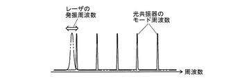
- the frequency at which the optical resonator 4 can resonate is generally called a mode frequency.
- the mode frequencies exist at predetermined frequency intervals, and when the frequency of the laser light introduced into the optical resonator 4 does not match this mode frequency, the optical No power is stored.
- the oscillation frequency of the laser light in the laser light source unit 1 is adjusted to match the mode frequency, the optical power is accumulated in the optical resonator 4.
- the laser light entering the optical resonator 4 is sharply cut off by the optical switch 3. Then, immediately before that, the light accumulated in the optical resonator 4 reciprocates between the pair of mirrors 47 and 48 a large number of times (actually, thousands to tens of thousands of times), and is enclosed in the measurement cell 40 during that time. The light is gradually attenuated by the absorption of the components in the measured gas. At that time, the photodetector 5 repeatedly detects the attenuation state of a part of the light leaking to the outside through one mirror 48 of the optical resonator 4.
- the absorption coefficient of the target component in the measured gas at the frequency of the laser light at that time is calculated. You can Then, the absolute concentration of the target component can be obtained from the absorption coefficient. Further, the absorption spectrum of the target component in the gas to be measured can be obtained by repeating the same measurement while scanning the oscillation frequency of the laser light in the laser light source unit 1.
- the optical resonator 4 is used to extend the effective distance through which the light passes through the gas to be measured, so that the difference between the ringdown times ⁇ and ⁇ 0 becomes large. Thereby, even a slight amount of light absorption due to a trace amount of the target component can be detected, and higher detection sensitivity can be realized as compared with other methods of laser absorption spectroscopy.
- the CRDS device can measure the concentration of the component in the measured gas with extremely high sensitivity. Therefore, the CRDS device is often used for the purpose of measuring the isotope ratio of CO 2 and H 2 O in the gas to be measured with high accuracy (see Patent Document 2, etc.). Further, the application of isotope ratio measurement using a CRDS device has been advanced in various fields such as production center identification of agricultural products (see Non-Patent Document 2).
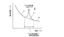
- FIG. 10 is a schematic diagram of the absorption spectrum of the measured gas in the vicinity of the peak wavelength of the 14 CO 2 absorption line. Most of the baseline of this absorption line peak is actually derived from absorption by 12 CO 2 and 13 CO 2 contained in high concentration, that is, the background. If this background is ignored, the concentration of the target component cannot be accurately obtained.
- the effective reflectance of the mirror decreases due to the adsorption of some components in the measurement gas, and the effective reflectance fluctuation and resonance due to minute fluctuations of the mirror or minute fluctuations of the incident light position. Variations in the cavity length, and further variations in the cavity length and the like may occur due to thermal expansion of the optical resonator caused by minute variations in temperature. Therefore, the longer the measurement time is, the higher the possibility that the measurement state changes during the measurement and the larger the change amount may be, and thus the concentration may not be accurately determined in some cases.
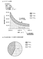
- 11 (a) is 14 absorption peak position of the CO 2 in a predetermined wave number range in the vicinity (wave number), 12 CO 2, each containing a stable isotope 12 C, 13 C carbon, 13 CO 2, and the 14 CO
- the absorption spectrum showing the relationship between the wave number and the absorption coefficient for 2 was obtained by calculation.
- FIG. 11 (b) is a 12 CO 2, 13 CO 2, and the results of calculating the contribution degree of absorption by 14 CO 2 in the absorption peak position of 14 CO 2.
- the bottom of the absorption peak of 13 CO 2 overlaps with the position of the absorption peak of 14 CO 2 .
- the wavenumber range of the measurement target is expanded to the spectrum region where 13 CO 2 absorption exists independently, and spectrum fitting is performed for each of 14 CO 2 and 13 CO 2 to obtain the absorption peak of 14 CO 2 .
- the single absorption peak of 14 CO 2 is obtained by separating and removing the absorption peak of 13 CO 2 overlapping at the position of, and this is evaluated.
- the absorption peak of 13 CO 2 alone cannot be confirmed. Therefore, the spectrum fitting cannot be correctly performed with respect to the absorption of 13 CO 2 , and the spectrum waveform corresponding to the estimated baseline becomes inaccurate.
- the spectrum obtained by repeating the measurement by CRDS while actually scanning the oscillation wavelength is the waveform shown by the solid line in FIG. 10, but even if the baseline is estimated from this waveform, as shown in FIG. It is not possible to estimate a baseline that reflects overlapping peaks. Therefore, the background cannot be accurately removed, and the absorption coefficient of the target component cannot be accurately obtained.
- the present invention has been made in view of the above-mentioned problems, and an object thereof is to provide a gas measuring device and a gas measuring method capable of obtaining an accurate absorption coefficient or concentration of a target component.
- the ring-down characteristics (degree of exponential decay of light intensity) in CRDS depend on temperature and pressure. Therefore, the present inventor has noticed that the ring-down characteristic, that is, the absorption coefficient changes depending on the pressure. This is because when the temperature of the gas to be measured is changed, the optical path length of the optical resonator and the reflectance of the mirror change due to the thermal expansion effect, which changes the mode frequency and mode line width of the optical resonator. Therefore, stable measurement becomes difficult. On the other hand, the pressure of the gas to be measured can be changed relatively easily and accurately. Then, the present inventor repeated simulation calculations and the like, and found that the degree of absorption by the same component could significantly change within a range of pressure that can be changed practically, and completed the present invention.
- the gas measuring method according to the present invention made to solve the above problems is a cavity ring-down absorption spectroscopy (CRDS), in the gas measuring method for determining the concentration of the target component contained in the measured gas,
- a first measurement step in which the wavelength of the absorption peak of the target component is measured by cavity ring-down absorption spectroscopy by irradiating the gas to be measured with laser light under a first pressure
- a second measurement step of performing measurement by cavity ring-down absorption spectroscopy by irradiating the gas to be measured with a laser beam under a second pressure different from the first pressure
- An operation step of calculating the concentration of the target component by performing an operation on the result of the first measurement step and the result of the second measurement step; Is to have.
- the gas measuring device made to solve the above problems is one device for carrying out the gas measuring method according to the present invention, and the gas to be measured is measured by the cavity ring-down absorption spectroscopy.
- a gas measuring device that determines the concentration of the target component in the A laser irradiation unit
- An optical resonator that includes a measurement cell in which a gas to be measured is contained, and that resonates the laser light emitted from the laser light irradiation unit and introduced into the measurement cell, A photodetector for detecting the laser light extracted from the optical resonator;
- a pressure adjusting unit for adjusting the pressure of the gas to be measured in the measurement cell,
- a control unit that controls the pressure adjusting unit when performing measurement by a cavity ring-down absorption spectroscopy for the gas to be measured in the measurement cell,
- An arithmetic processing unit that calculates the concentration of the target component by performing an arithmetic operation on a plurality of measurement results obtained under different pressures under the control
- the control unit in order to carry out the gas measuring method according to the present invention, the control unit, A first measurement step in which the wavelength of the absorption peak of the target component is measured by cavity ring-down absorption spectroscopy by irradiating the gas to be measured with laser light under a first pressure; A second measurement step of performing measurement by cavity ring-down absorption spectroscopy by irradiating the gas to be measured with a laser beam under a second pressure different from the first pressure;
- the laser light irradiation unit and the light detection unit may be controlled so as to carry out the above.
- the target component is usually a component contained in the gas to be measured at a relatively low concentration, and is typically an isotope having a low content ratio in isotopes having the same chemical formula, for example, 14 CO. 2 , DHO (heavy water), 15 NH 3 and the like.
- the pressure of the measurement gas absorption by 14 CO 2 is in the other isotope
- the first pressure in the present invention is the pressure under the optimum (or close to optimum) condition for measuring 14 CO 2 , and the wavelength of the absorption peak of the target component under the pressure.
- the wavelength of the absorption peak due to 13 CO 2 and the wavelength of the absorption peak due to 14 CO 2 are quite close to each other, and as described above, the absorption peak due to 14 CO 2 in the absorption spectrum has an absorption peak due to 13 CO 2. May overlap.
- the second pressure in the present invention is, for example, when the absorption by the target component 14 CO 2 is negligible as compared with the absorption by 12 CO 2 , 13 CO 2 or the like other than the target component present in the gas to be measured, or sufficient. It is the pressure when it is small.
- the target component in the second measurement step is measured.
- the result (ring down rate or ring down time) in which absorption by only the components other than is reflected is obtained. That is, since the measurement result is not substantially influenced by the absorption due to the target component, the absorption at that time can be regarded as the background. Therefore, in the calculation step, the result of the measurement by the two CRDS performed under the condition that the pressure of the gas to be measured is different is used to perform the calculation processing to remove or reduce the influence of the background, and the target component Calculate the concentration of.
- the wavelength of the laser light used in the measurement in the second measurement step may be the same as the wavelength of the laser light used in the measurement in the first measurement step. That is, even if the measurement by the CDRS method is performed using the laser light of the same wavelength in the first measurement step and the second measurement step, the signal corresponding to the absorption by the low concentration component such as 14 CO 2 overlaps with this signal. It is possible to separate the signal corresponding to the absorption by the higher concentration component such as 12 CO 2 , 13 CO 2 and the like, and calculate the absorption coefficient and concentration of the low concentration component.
- the target component is 14 CO 2
- the pressure of the gas to be measured is set higher than the optimum pressure condition for measuring 14 CO 2
- the amount of 12 CO 2 or 13 CO 2 will be higher than the absorption by 14 CO 2.
- the absorption by 2 is greatly increased.
- the background level is increased overall.
- the accuracy of the background measurement result is improved, and by performing background removal with high accuracy, the concentration of the target component can be obtained more accurately.
- first pressure and the second pressure may be determined in advance or by experiments depending on the target component.
- the ratio of the absorption by the multiple components differs depending on the pressure.
- the wavelength of the absorption peak of the target component is measured by cavity ring-down absorption spectroscopy
- a simultaneous equation based on the result of the first measurement step and the result of the second measurement step is created, and the simultaneous equations are solved to obtain a concentration other than the concentration of the target component in the measured gas. You may make it calculate the density
- the control unit performs a measurement by a cavity ring-down absorption spectroscopy with respect to the wavelength of the absorption peak of the target component during the measurement under the second pressure
- the arithmetic processing unit creates a simultaneous equation based on the result under the first pressure and the result under the second pressure, and solves the simultaneous equation to obtain the object in the measured gas.
- the concentration of the target component may be calculated by removing or reducing the influence of absorption other than the component concentration.
- the concentration and absorption coefficient of the target component since the influence of absorption by the target component is included in the background, the concentration and absorption coefficient of the target component, by solving the simultaneous equations with the concentration and absorption coefficient of components other than the target component as unknown values, Calculate the concentration of only the target component. As a result, even if the pressure of the gas to be measured cannot be changed to a pressure at which the effect of absorption by the target component is completely eliminated, the effect of the background can be appropriately removed and the absorption coefficient of the target component or The concentration can be obtained.
- the wavelength of the laser light used in the measurement in the second measurement step does not necessarily have to be the same as the wavelength of the laser light used in the measurement in the first measurement step. That is, as another aspect of the gas measuring method according to the present invention, in the second measuring step, the cavity ring-down absorption is performed at a wavelength different from the wavelength of the absorption peak of the target component and in which the influence of the absorption by the target component can be ignored. Measurement by spectroscopy, In the calculation step, the concentration of a component other than the target component in the measured gas under the second pressure is estimated based on the result of the second measurement step, and from the concentration, the first measurement step is performed. It is advisable to estimate the contribution of absorption of components other than the target component in the absorption coefficient obtained from the above result, and perform a calculation to remove the influence.
- the control unit measures by a cavity ring-down absorption spectroscopy a wavelength that is different from the wavelength of the absorption peak of the target component and in which the influence of absorption by the target component can be ignored.
- the arithmetic processing unit estimates the concentration of a component other than the target component in the measured gas under the second pressure based on the result under the second pressure, and from the concentration, calculates the It is also possible to estimate the contribution of absorption of a component other than the target component in the absorption coefficient obtained from the result under one pressure and perform a calculation to remove the influence.
- the wavelength of the laser light used for the measurement in the second measurement step may be set to an appropriate wavelength that is clear in advance that the effect of absorption by the target component can be ignored.
- the measurement result of the measurement in the second measurement step is not substantially affected by the absorption of the target component.
- the absorption is due to only the components other than the target component, that is, the background, and thus the background can be easily removed as compared with the case of solving the simultaneous equations as described above. Even if the pressure of the gas to be measured cannot be changed to a pressure at which the effect of absorption by the target component is completely eliminated, the background removal process can be performed relatively easily.
- the wavelength of the laser light in the above aspect, it is not generally necessary to measure the absorption coefficient at a wavelength far away as in the case of using another absorption peak of the target component, and within a narrow wavelength range. It is enough to switch the wavelength with. Therefore, it can be realized without problems with a general light source or a mirror in a CRDS device.
- the pressure adjusting unit forces a part of the measured gas from the measurement cell to the outside from the state in which the measured gas is enclosed in the measuring cell at the second pressure. It is possible to adjust the pressure of the gas to be measured in the measurement cell to the first pressure by discharging the gas.
- opening / closing valves respectively provided in the gas introduction pipe and the gas discharge pipe connected to the measurement cell, a vacuum pump for discharging the measured gas in the measurement cell to the outside through the gas discharge pipe, and the measurement cell
- a pressure control unit that controls the opening / closing operation of the opening / closing valve and the operation of the vacuum pump while monitoring the pressure with the pressure detection unit.
- the pressure adjusting unit remains in a state in which the gas to be measured is supplied into the measurement cell and the gas to be measured is sealed at a first predetermined pressure, without being supplied first.
- the pressure of the measured gas in the measurement cell may be adjusted to the second predetermined pressure by additionally supplying and sealing the measured gas in the measurement cell.
- the opening and closing valves respectively provided in the gas introduction pipe and the gas discharge pipe connected to the measurement cell, the feed pump for supplying the gas to be measured into the measurement cell through the gas introduction pipe, and the A configuration may include a pressure detection unit that detects the pressure of gas, and a pressure control unit that controls the opening / closing operation of the opening / closing valve and the operation of the delivery pump while monitoring the pressure by the pressure detection unit. it can. According to these configurations, the pressure of the gas to be measured in the measurement cell can be easily adjusted to a target value.
- the background caused by absorption by components other than the target component in the measured gas is removed with high accuracy by performing the measurement twice on the measured gas, and the accurate concentration of the target component is determined. Can be obtained. This eliminates the need for a large number of repeated measurements required to estimate the background spectrum, and thus the measurement time can be shortened and the measurement throughput can be improved. Further, since the measurement time is short, accurate concentration measurement can be performed even if the target component is relatively unstable, such as a radioisotope having a short half-life.
- the effective mirror reflectance is lowered due to the adsorption of a part of the measurement gas on the mirror, and the minute fluctuation of the mirror and the minute fluctuation of the incident light position are caused.
- Minimal or close to the influence on the change of the measurement condition that occurs during measurement such as the fluctuation of the effective reflectance and the fluctuation of the resonator length, and the fluctuation of the resonator length due to the thermal expansion of the optical resonator caused by the minute fluctuation of temperature. Can be kept in a state.
- the absorption coefficient and the concentration can be accurately obtained.
- FIG. 1 is a configuration diagram of a main part of a CRDS device that is an embodiment of the present invention.
- Graph showing the calculation result of the absorption characteristics due to CO 2 isotope gas when the pressure is 1013.25Pa.
- Graph showing the calculation result of the absorption characteristics due to CO 2 isotope gas when the pressure is 10132.5Pa.
- 6 is a flowchart showing an example of a measurement and processing procedure when obtaining the concentration of a target component in the CRDS device of this embodiment.
- 6 is a flowchart showing another example of the procedure of measurement and processing when obtaining the concentration of the target component in the CRDS device of this embodiment.
- FIG. 3 is a schematic diagram showing a relationship between a mode frequency in an optical resonator and an oscillation frequency of laser light.
- 14 is a schematic view of the absorption spectrum of the gas to be measured in the vicinity of the peak wavelength of the 14 CO 2 absorption line. Shows the 12 CO 2, 13 CO 2, and the calculation result of the contribution degree of absorption by 14 CO 2 in the absorption peak position of FIG.
- Both Figure 11 (a) and 12 (a) is a 12 CO 2, 13 CO 2, and the calculation result of the absorption spectrum for 14 CO 2 in the vicinity of the absorption peak position of 14 CO 2, 11 (
- the difference between a) and FIG. 12A is only the assumed pressure of the measured gas. That is, when the pressure is relatively low (here 0.03 atm), the absorption peak of 14 CO 2 is clearly observed, but the absorption peak of 13 CO 2 whose skirt overlaps this absorption peak of 14 CO 2 is observed. The peak cannot be confirmed alone. Therefore, the spectrum fitting cannot be performed correctly for the absorption of 13 CO 2 , and it is difficult to accurately estimate the background (baseline of the peak).
- gas molecules generally have a plurality of absorption peaks according to rotation, translation, and vibration, even if signals are overlapped with each other at an absorption peak at a certain wavelength as described above, different wavelengths are used.
- the absorption coefficient can be measured by using another absorption peak in.
- the light source and the mirror used in the CRDS device are effective only in a limited wavelength range, and often cannot correspond to the wavelengths of a plurality of absorption peaks of the target component in the gas to be measured. In such cases, the reality is that there is no effective way to measure the absorption coefficient.
- the absolute concentration of the component other than the target component can be calculated based on the absorption coefficient. From this absolute concentration, it is possible to estimate the baseline spectrum at the absorption peak position of 14 CO 2 when the pressure of the measured gas is relatively low as shown in FIG. Then, the absorption coefficient of pure 14 CO 2 is obtained by subtracting the baseline from the absorption coefficient obtained from the measurement result obtained by carrying out the measurement by CRDS in the state where the pressure of the gas to be measured is relatively low. From the absorption coefficient, the absolute concentration of only the target component, 14 CO 2, can be calculated.
- the degree of absorption of 14 CO 2 may not be negligible. Even in that case, the absolute concentration of only 14 CO 2, which is the target component, can be calculated by solving simultaneous equations as described later.
- the measurement result that reflects the baseline spectrum that is not affected by the absorption by the target component is obtained, and the pure result is obtained using this. It is also conceivable to obtain the absorption coefficient of 14 CO 2 . This will also be described later.
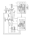
- FIG. 1 is a block diagram of the essential parts of the CRDS device of this embodiment.
- the CRDS device of this embodiment includes a laser light source unit 1, a laser drive unit 2, an optical switch 3, an optical resonator 4, and a photodetector 5 as a measurement system.
- the optical resonator 4 includes a substantially cylindrical measurement cell 40 in which a sample gas, which is a gas to be measured, is housed, and a pair of high-reflectance mirrors 47 and 48 arranged at opposite ends of the measurement cell 40. ,including.
- a gas introduction pipe 41 and a gas discharge pipe 43 are connected to the measurement cell 40, an introduction valve 42 is provided in the gas introduction pipe 41, and a discharge valve 44 and a vacuum pump 45 are provided in the gas discharge pipe 43.
- the measurement cell 40 is provided with a pressure sensor 46 for detecting the pressure of the gas contained in the cell 40.
- the control unit 6 controls each unit such as the laser drive unit 2 in order to execute the measurement and data processing described later, and as a functional block, the measurement control unit 61, the laser control unit 62, the pressure control unit 63, And a measurement parameter storage unit 64 and the like.
- measurement parameters such as the wave number (or wavelength) of laser light and pressure are stored in advance in correspondence with the type of component to be measured.
- the data processing unit 7 to which the detection signal from the photodetector 5 is input has, as functional blocks, a measurement data storage unit 71, a ringdown time calculation unit 72, a concentration calculation unit 73, a calculation known information storage unit 74, and the like. Equipped with.
- the measurement data storage unit 71 includes an analog-digital converter that digitizes an analog detection signal.
- the output unit 8 connected to the data processing unit 7 is, for example, a display monitor.
- the measurement gas is CO 2
- the description will be oriented to the concrete where the target component is a 14 CO 2 which is one of the isotopes of CO 2 as an example.
- the concentration measurement of 14 CO 2 containing carbon 14 C, which is a radioactive isotope, is widely used in various fields.
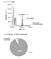
- FIG. 2B is a pie chart showing the breakdown of the factors of absorption at the wave number of light (the wave number of the absorption peak of 14 CO 2 ) shown under condition 1 in FIG. In these calculations, it was assumed that the temperature was 200 K, the 14 CO 2 concentration was 2 ⁇ 10 ⁇ 12 , and the CO 2 concentration other than 14 CO 2 was 0.2. Further, it is assumed that CO 2 isotopes other than 14 CO 2 contained in the gas to be measured are introduced into the measurement cell 40 by the natural isotope abundance ratio.
- the absorption coefficient at the wave number of the absorption peak of 14 CO 2 is calculated to be 3.49 ⁇ 10 ⁇ 10 .
- the absorption coefficient at the wave number of the absorption peak of 14 CO 2 is calculated to be 3.49 ⁇ 10 ⁇ 10 .
- about 82% of the light absorption at this time is due to 14 CO 2 , but the remaining about 18% is due to CO 2 isotopes other than 14 CO 2 ( 12 CO 2 , 13 CO 2 ). Therefore, to calculate the exact concentration of 14 CO 2, it is necessary to subtract the baseline due to the absorption of CO 2 other than 14 CO 2. To obtain the baseline spectrum, it is sufficient to know the concentration of CO 2 other than 14 CO 2 .
- 14 CO 2 absorption coefficient due to CO 2 other than may be Motomare from the measured data
- the problem here is steeply as absorption peak by 14 CO 2 is shown in FIG. 2 (a) as observed, 14 under the measurement conditions suitable for CO 2, 14 CO data reflecting the absorption for 2 absorption of light by the CO 2 other than small is not correctly obtained, that Is.
- seeking spectral baseline due to perform measurements by changing the pressure of the gas to be measured the absorption of CO 2 other than 14 CO 2 by utilizing the measurement results ..
- the measurement is performed on the gas to be measured while the pressure is always kept constant.
- the absorption coefficient of a component in gas depends on temperature, pressure, wavelength of light, and the like. Therefore in general, the pressure in measuring the absorption by 14 CO 2, the difference between the absorption coefficient and absorption coefficient of CO 2 other than 14 CO 2 of 14 CO 2 in the wave number of the absorption peak by 14 CO 2 is an object component
- the pressure is set so as to satisfy the conditions such as being as large as possible. This is because such pressure is considered to be the condition with the best SN ratio in observing the absorption peak due to 14 CO 2 .
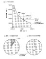
- FIG. 3A shows the result of calculation of the absorption spectrum by CRDS for the CO 2 isotope gas when the pressure is 10132.5 Pa (0.1 atm), which is 10 times that in the case of FIG. 2A.
- FIG. 3 (b) is a pie chart showing the breakdown of absorption factors under the wave number shown in FIG. 3 (a) under condition 2 (the same as the wave number under condition 1 above), and FIG. 3 (c) is shown in FIG. 3 (a).
- 6 is a pie chart showing a breakdown of factors of absorption in a wave number shown in Condition 3 (an appropriate wave number smaller than that in Condition 1).
- the calculation conditions other than the pressure are the same as in the case of FIG.
- the wave number of the absorption peak due to 12 CO 2 exists in the range deviating to the left from the graph shown in FIG. 3 (a), but the height and the peak width of the absorption peak rapidly increase as the pressure increases.
- the height of the absorption peak due to 14 CO 2 at this time is 10 times or more the height of the absorption peak in the graph shown in FIG. 2 (a), but the absorption peak is almost completely buried in the tailing of the absorption peak due to 12 CO 2. It's gone. That is, such the background overall level Higher pressure of the measurement gas is considerably high, it is easy to detect the absorption by CO 2 other than 14 CO 2, or it can be seen that the improved accuracy of the detection.
- the same measured object is obtained under the pressure condition in which the background becomes high. Perform a CRDS measurement on the gas.
- the ratio of absorption by 14 CO 2 remains about 7% at the wave number of condition 2, but the ratio of absorption by 14 CO 2 at the wave number of condition 3 is 0%.
- the measurement under a relatively high pressure for obtaining this background may be performed under any one of the conditions 2 and 3, but depending on which condition the measurement is performed, the method of processing the measurement results is different. different.
- the wave number of Condition 3 is not limited to the position shown in FIG. 3 (a), and the absorption peak of 14 CO 2 is buried in the background and the background level is high (that is, 14 in FIG. 3 (a). It can be appropriately determined as long as it is on the left side of the position of the absorption peak of CO 2 ) and within the adjustable range of the wave number of the laser light.
- the concentration of 14 CO 2 calculated as described above does not include the influence of absorption by CO 2 isotopes other than 14 CO 2 or the influence is negligible, high accuracy is obtained.
- the concentration of 14 CO 2 in the measured gas can be obtained.
- the pressure condition and the wave number of the laser beam used for each measurement may be appropriately determined in advance in accordance with the type of the component to be measured.
- the measurement may be performed under different pressure conditions in which the absorption rate of each isotope gas increases, and the concentration of each isotope gas may be calculated based on the three measurement results.
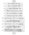
- FIGS. 4 and 5 show flowcharts of the operation of measuring the concentration of the target component ( 14 CO 2 ) in the gas to be measured in the CRDS device of this example.
- FIG. 4 is a flowchart showing an example of a measurement and processing procedure when background removal is performed using the measurement result under the condition 3.
- the ringdown time under each pressure in the state where the measured gas containing CO 2 is not introduced into the measurement cell 40 is preliminarily measured and stored in the calculation known information storage unit 74. .. Further, a priori information such as the absorption cross-section of the target component used in the concentration calculation is also stored in the calculation known information storage unit 74.
- the pressure control unit 63 opens the introduction valve 42 with the discharge valve 44 closed, and introduces the gas to be measured into the measurement cell 40.
- the introduction valve 42 is closed to fill the measurement cell 40 with the gas to be measured (step S1).
- the pressure control unit 63 opens the discharge valve 44 and operates the vacuum pump 45 to start discharging the gas to be measured in the measurement cell 40 through the gas discharge pipe 43.
- the discharge valve 44 is closed (step S2). As a result, the gas to be measured having the pressure P3 is enclosed in the measuring cell 40.
- the laser control unit 62 operates the laser light source unit 1 through the laser drive unit 2 so that the wave number of the laser light becomes a predetermined background (BG) measurement value ⁇ 3 (step S3). Then, the measurement control unit 61 executes the measurement under the laser light wave number ⁇ 3 and the pressure P3. That is, the gas to be measured in the measurement cell 40 is irradiated with laser light, and the laser light is cut off by the optical switch 3 at a predetermined timing. Then, the data detected by the photodetector 5 is collected from immediately before shutting off the laser light until a predetermined time elapses (step S4). At this time, the measurement data under high pressure obtained by the photodetector 5 is temporarily stored in the measurement data storage unit 71. The measurement data at this time is data including the ringdown time t3 under the condition 3 as information.
- BG background
- the pressure control unit 63 opens the discharge valve 44 again and operates the vacuum pump 45 to start discharging the measured gas in the measurement cell 40 to the outside through the gas discharge pipe 43.
- the discharge valve 44 is closed (step S5).
- the measurement gas having a pressure P1 lower than the pressure P3 is sealed in the measurement cell 40.
- the laser control unit 62 operates the laser light source unit 1 through the laser drive unit 2 so that the wave number of the laser light becomes the target component measurement value ⁇ 1 (step S6). Then, the measurement control unit 61 executes the measurement under the laser light wave number ⁇ 1 and the pressure P1 and acquires the measurement data for a predetermined period, similarly to step S4 (step S7). At this time, a series of measurement data obtained by the photodetector 5 is also temporarily stored in the measurement data storage unit 71.
- the measurement data under the low pressure is data including the ringdown time t1 under the condition 1 shown in FIG. 2A as information.
- step S5 in order to reduce the pressure in the measurement cell 40, in step S5, a part of the measurement gas in the measurement cell 40 is discharged to the outside, so the measurement gas measured in steps S4 and S7 is measured.
- the measurement gas measured in steps S4 and S7 are not exactly the same.
- the distribution of the components in the gas to be measured in the measurement cell 40 can be considered to be uniform, it can be considered that the gases measured in steps S4 and S7 are the same gas to be measured and only the pressure is different. it can.
- the ring-down time calculation unit 72 calculates the ring-down time t3 based on the measurement data stored in the measurement data storage unit 71 under high pressure (step S8). Then, the concentration calculation unit 73 calculates the absorption coefficient based on the calculation result and the ringdown time in the absence of the measured gas under the condition 3 stored in the calculation known information storage unit 74, and The concentration is obtained from the absorption coefficient (step S9).
- These calculation methods are the same as conventional ones, and for example, the above equations (1) and (2) may be used. At this time, the influence of absorption by 14 CO 2 can be ignored, so that the concentration of the CO 2 isotope gas other than 14 CO 2 in the measured gas can be determined in step S8.
- the ring-down time calculation unit 72 calculates the ring-down time t1 based on the measurement data stored in the measurement data storage unit 71 under low pressure (step S10). Then, the concentration calculation unit 73 calculates the absorption coefficient from the calculation result and the ringdown time in the absence of the measured gas under the condition 1 stored in the calculation known information storage unit 74 (step S11). .. At this time, the absorption coefficient of the CO 2 isotope gas containing 14 CO 2 in the measured gas is obtained.
- step S8 the concentration of CO 2 isotope gas excluding 14 CO 2 is obtained. Therefore, the concentration calculator 73 calculates the absorption coefficient of the CO 2 isotope gas excluding 14 CO 2 under the pressure and laser wave number of Condition 1 from this concentration. Since this absorption coefficient is the background, CO subtracted absorption coefficient due to CO 2 isotope except 14 CO 2 from the absorption coefficient due to 2 isotopic gas, calculates the absorption coefficient by 14 CO 2 in the condition 1 containing 14 CO 2 Then, the concentration of only 14 CO 2 is calculated from this absorption coefficient (step S12). Then, the result is output from the output unit 8. As described above, the CRDS device of the present embodiment can provide the user with accurate information on the concentration of only 14 CO 2 from which the background has been removed.
- Steps S21 and S22 are exactly the same as steps S1 and S2 described above, and the gas to be measured having the pressure P3 is enclosed in the measurement cell 40 by these steps.
- the laser control unit 62 operates the laser light source unit 1 through the laser drive unit 2 so that the wave number of the laser light becomes the target component measurement value ⁇ 1 (step S23). Then, the measurement control unit 61 executes the measurement under the laser light wave number ⁇ 1 and the pressure P3, and acquires the measurement data (step S24).
- the measurement data under the high pressure is data including the ringdown time t2 under the condition 2 as information.
- step S25 the pressure of the gas to be measured enclosed in the measuring cell 40 is reduced to the target component measuring pressure P1.
- the measurement control unit 61 executes the measurement under the laser light wave number ⁇ 1 and the pressure P1 to obtain the measurement data (step S26).
- the measurement data under the low pressure is data similar to the example of FIG. 4 and including the ring down time t1 under the condition 1 as information.
- the ringdown time calculation unit 72 calculates the ringdown time t2 based on the measurement data stored in the measurement data storage unit 71 under high pressure (step S27).
- the concentration calculator 73 calculates the absorption coefficient ⁇ 2 from the calculation result and the ring-down time in the absence of the measured gas under the condition 2 (step S28). At this time, the effect of absorption by 14 CO 2 cannot be neglected. Therefore, what is obtained here is the absorption coefficient by 14 CO 2 in the measured gas under the condition 2 and the absorption coefficient by CO 2 isotope gas other than 14 CO 2. It is the added value.
- the ring-down time calculation unit 72 calculates the ring-down time t1 based on the measurement data under the low pressure stored in the measurement data storage unit 71 (step S29). This is the same as step S10. Then, the concentration calculator 73 calculates the absorption coefficient ⁇ 1 from the calculation result and the ring-down time when the gas under measurement is not present under the condition 1 (step S30). At this time, the value obtained by adding the absorption coefficient by 14 CO 2 in the measured gas under the condition 1 and the absorption coefficient by the CO 2 isotope other than 14 CO 2 is obtained.
- the concentration y of CO 2 isotope other than the concentration x and 14 CO 2 of 14 CO 2 is an unknown value, respectively. Therefore, an equation showing the relationship between the absorption coefficient ⁇ 1 and the concentrations x and y obtained by the measurement under the condition 1 and the relationship between the absorption coefficient ⁇ 2 and the concentrations x and y obtained by the measurement under the condition 2 are shown. The following equations and are created as simultaneous equations. Then, the concentration calculator 73 calculates the concentration of only 14 CO 2 by solving this simultaneous equation (step S31). As described above, the accurate concentration of only 14 CO 2 from which the background has been removed can be calculated and provided to the user.
- the concentration may be derived. That is, under each measurement condition (that is, conditions 1, 2, and 3), the value of the absorption coefficient observed for various combinations of concentrations of 14 CO 2 and other CO 2 isotopes is obtained in advance, and the database is obtained. Turn it into. And if the absorption coefficient is Motoma' based on the measurement data, by performing the database search the absorption coefficient as input, derives the concentration of the corresponding 14 CO 2 concentration and 14 CO 2 other than the CO 2 isotope You may do so.
- the concentration of 14 CO 2 which is one of the CO 2 isotopes
- the CRDS device of this embodiment can also be used for the analysis of other components in the gas to be measured.
- the measurement of the H 2 O isotope in the gas to be measured which has a high utility value along with the measurement of the CO 2 isotope will be briefly described.
- FIG. 6B is a pie chart showing the breakdown of the factors of absorption at the wave number shown in Condition 1 in FIG. 6A.
- FIG. 7 (a) is an absorption spectrum by
- FIG. 7B is a pie chart showing the breakdown of factors of absorption at the same wave number as the condition 1 in FIG. 7A.
- the temperature was 353 K and the concentration of H 2 O 2 in the measured gas was 0.03. Further, it is assumed that all the H 2 O isotopes contained in the gas to be measured are introduced into the measurement cell 40 by the natural isotope abundance ratio.
Landscapes
- Chemical & Material Sciences (AREA)
- Physics & Mathematics (AREA)
- Health & Medical Sciences (AREA)
- Life Sciences & Earth Sciences (AREA)
- General Physics & Mathematics (AREA)
- Analytical Chemistry (AREA)
- Biochemistry (AREA)
- General Health & Medical Sciences (AREA)
- Immunology (AREA)
- Pathology (AREA)
- Spectroscopy & Molecular Physics (AREA)
- Engineering & Computer Science (AREA)
- Combustion & Propulsion (AREA)
- Food Science & Technology (AREA)
- Medicinal Chemistry (AREA)
- Investigating Or Analysing Materials By Optical Means (AREA)
Abstract
測定セル(40)中に被測定ガスを所定圧力となるように導入したあと、レーザ光源部(1)、光スイッチ(3)、光共振器(4)、及び光検出器(5)により、CRDSによる所定の波数における測定を行う。次に、測定セル(40)内の被測定ガスの一部を排出して圧力を下げ、目的成分である14CO2の吸収ピークの波数における測定を行う。高圧力の下での測定時には14CO2による吸収の影響が無視できるため、リングダウン時間から12CO2等のバックグラウンドの濃度が求まる。低圧力の下での測定データから求まるリングダウン時間から算出される吸収係数にはバックグラウンドの影響が含まれるが、高圧力の下で求めたバックグラウンドの濃度から低圧力の下でのバックグラウンドの吸収係数を計算することができる。濃度演算部(73)はそれを用いてバックグラウンドの影響を除去した14CO2のみの吸収係数を求め、14CO2のみの濃度を算出する。異なる圧力の下で実施された2回の測定の結果から14CO2等の目的成分の精度の高い絶対濃度を得ることができ、従来より測定時間を短縮することができる。
Description
本発明は、レーザ光に対する吸収を利用して、被測定ガス中の特定成分の濃度を測定するガス測定装置及びガス測定方法に関する。
被測定ガス中の特定成分の濃度を測定する手法として、レーザ吸収分光法が広く利用されている。レーザ吸収分光法には幾つかの手法が知られているが、その一つの手法として、キャビティリングダウン吸収分光法(Cavity Ring-down Absorption Spectroscopy、以下、慣用に従って「CRDS」と称す)がある。CRDSは、光共振器を用いて光吸収のための実効光路長を長くすることにより、検出可能な吸光度、つまりはその検出感度を大幅に改善できる手法である(非特許文献1など参照)。
橋口幸治、「ガス中微量水分の高効率な計測技術に関する調査研究」、産業技術総合研究所、産総研計量標準報告、2015年10月、Vol.9、No.2、pp.185-205
鈴木彌生子、「キャビティリングダウン分光分析法を用いた果物および野菜の水分の酸素・水素同位体比」、日本水文科学会誌、2016年、第46巻、第2号、pp.157-166
パン・ドゥ(Pan Du)ほか2名、「インプルーブド・ピーク・デテクション・イン・マス・スペクトラム・バイ・インコーポレーティング・コンティニュアス・ウェブレット・トランスフォーム-ベースド・パターン・マッチング(Improved peak detection in mass spectrum by incorporating continuous wavelet transform-based pattern matching)」、オックスフォード・ユニバーシティ・プレス(Oxford University Press)、バイオインフォマティックス(Bioimformatics)、2006年、Vol.22、No.17、pp.2059-2065
本発明の課題について、図面を参照して具体的に説明する。
図8は、一般的なCRDS装置の概略構成図である。図8において、レーザ光源部1から射出された所定波長のレーザ光は、光スイッチ3を通して、被測定ガスが収容されている測定セル40に導入される。筒状である測定セル40の両端には一対の高反射率(ごく僅かに光が透過する)のミラー47、48が対向して配置されており、測定セル40、ミラー47、48は光共振器4を構成する。この光共振器4は例えばレーザ装置等で一般的に用いられているものと同様のファブリペロー共振器であり、共振し得る光の波長(周波数)は共振条件に応じて決まっている。なお、光共振器4は、2枚のミラーを対向して配置した構成の共振器でなく、3枚以上のミラーで構成されるリング型の共振器であってもよい。
図8は、一般的なCRDS装置の概略構成図である。図8において、レーザ光源部1から射出された所定波長のレーザ光は、光スイッチ3を通して、被測定ガスが収容されている測定セル40に導入される。筒状である測定セル40の両端には一対の高反射率(ごく僅かに光が透過する)のミラー47、48が対向して配置されており、測定セル40、ミラー47、48は光共振器4を構成する。この光共振器4は例えばレーザ装置等で一般的に用いられているものと同様のファブリペロー共振器であり、共振し得る光の波長(周波数)は共振条件に応じて決まっている。なお、光共振器4は、2枚のミラーを対向して配置した構成の共振器でなく、3枚以上のミラーで構成されるリング型の共振器であってもよい。
光共振器4において共振し得る周波数は一般にモード周波数と呼ばれる。図9に示すように、モード周波数は所定の周波数間隔で存在し、光共振器4に導入されたレーザ光の周波数がこのモード周波数と一致しない場合には、該光共振器4内に光のパワーは蓄積されない。一方、レーザ光源部1でのレーザ光の発振周波数がモード周波数と一致するように調整されると、光共振器4内に光のパワーが蓄積される。
CRDS装置では、光のパワーが光共振器4内に十分に蓄積されたあと、該光共振器4へ入射するレーザ光を光スイッチ3によって急峻に遮断する。すると、その直前に光共振器4内に蓄積されていた光は一対のミラー47、48の間を多数回(実際には数千~数万回)往復し、その間、測定セル40内に封入されている被測定ガス中の成分による吸収によって光は徐々に減衰していく。その際に、光共振器4の一方のミラー48を経て外部へと漏れ出る一部の光の減衰の状態を光検出器5によって繰り返し検出する。この光検出器5により検出したデータに基づいて光の減衰の時定数(リングダウン時間)を求めることで、そのときのレーザ光の周波数における被測定ガス中の目的成分の吸収係数を算出することができる。そして、その吸収係数から目的成分の絶対濃度を求めることができる。また、レーザ光源部1におけるレーザ光の発振周波数を走査しながら同様の測定を繰り返すことにより、被測定ガス中の目的成分の吸収スペクトルを得ることもできる。
被測定ガス中の目的成分の吸収係数αを求めるには、通常、次の(1)式が用いられる(特許文献1等参照)。
α=1/c{(1/τ)-(1/τ0)} …(1)
ここで、cは光速、τは測定セル40内に被測定ガスが収容されているときのリングダウン時間、τ0は測定セル40内に被測定ガスが収容されていない(例えば真空状態である)とき或いは被測定ガス中の成分による吸収が全く無視できるときのリングダウン時間である。また、目的成分(吸収物質)の吸収係数α、数密度n、吸収断面積σの関係は次の(2)のようになる。
α=nσ …(2)
α=1/c{(1/τ)-(1/τ0)} …(1)
ここで、cは光速、τは測定セル40内に被測定ガスが収容されているときのリングダウン時間、τ0は測定セル40内に被測定ガスが収容されていない(例えば真空状態である)とき或いは被測定ガス中の成分による吸収が全く無視できるときのリングダウン時間である。また、目的成分(吸収物質)の吸収係数α、数密度n、吸収断面積σの関係は次の(2)のようになる。
α=nσ …(2)
したがって、(1)、(2)式を用いてリングダウン時間τ、τ0から、吸収断面積が既知である成分についての絶対濃度を計算することができる。CRDS装置では、光共振器4を用いて光が被測定ガスを透過する実効的な距離を伸ばしているため、リングダウン時間τ、τ0の差が大きくなる。それによって、微量な目的成分によるごく僅かな光吸収も検出することができ、他の方式のレーザ吸収分光法に比べて高い検出感度を実現することができる。
上述したようにCRDS装置では、非常に高い感度で以て被測定ガス中の成分の濃度を測定することができる。そのため、CRDS装置は、被測定ガス中のCO2やH2Oの同位体比を高い精度で以て測定する目的でしばしば用いられる(特許文献2等参照)。また、CRDS装置を用いた同位体比測定の応用は、農産物の産地特定等の様々な分野で進んでいる(非特許文献2参照)。
しかしながら、例えば炭素の放射性同位体14Cを含む14CO2(天然同位体存在比:1×10-12)のように、被測定ガス中にごく微量しか含まれない成分の濃度を測定したい場合、その被測定ガスに含まれる別の成分による吸収の影響、つまりはバックグラウンドが無視できない。図10は、14CO2吸収線のピーク波長付近における被測定ガスの吸収スペクトルの概略図である。この吸収線ピークのベースラインは実際にはその殆どが、高い濃度で含まれる12CO2や13CO2による吸収に由来するもの、つまりはバックグラウンドである。このバックグラウンドを無視してしまうと目的成分の濃度を正確に求めることができない。
そこで、高い精度で以て比較的微量である同位体ガスの濃度を測定したい場合、従来、次のようにしてバックグラウンドを除去する作業が行われていた。
即ち、レーザ光の発振波長を所定の範囲で変化させながら、測定対象である同位体ガスの吸収ピーク付近の複数の波長でそれぞれCRDSによる測定を行い、その測定結果から吸収係数をそれぞれ算出する。そして、異なる波長に対してそれぞれ得られた複数の吸収係数に基づき、フォークト(Voigt)関数やローレンツ(Lorentz)関数によるフィッティング処理を行うことで、バックグラウンド(図10でいえば、14CO2以外のガス種による吸収)のスペクトル波形を推定する。即ち、図10ではA部やB部のスペクトル波形から、ピークのベースラインに相当するC部のスペクトル波形を推定する。そして、その推定したスペクトル波形を用いてバックグラウンド除去を行うことで、測定対象である同位体ガスのみの吸収係数を求め、その吸収係数から濃度を算出する。
バックグラウンドのスペクトル波形のフィッティングを精度良く行うには、或る程度多くの波長における吸収係数を測定によって求めることが必要である。そのため、一つの被測定ガスに対して多数回の測定を行う必要があり測定時間が長くなる。もちろん、こうしたバックグラウンドのスペクトル波形の推定は、被測定ガスが変わる毎に行う必要がある。
測定中には、測定ガス中の一部の成分の吸着によるミラーの実効的な反射率の低下や、ミラーの微小な変動或いは入射光位置の微小な変動による実効的な反射率の変動や共振器長の変動、さらには温度の微小な変動によって生じる光共振器の熱膨張による共振器長等の変動が生じ得る。そのため、測定時間が長引くほど、測定途中で測定状態が変化する可能性が高く又その変化量が大きくなる可能性があり、これにより正確に濃度を求めることができない場合がある。
また、以下に説明するように、上述したように推定したベースラインに相当するスペクトル波形が正確でない場合、フィッティングを行ったとしても濃度を正確に求めることができない。図11(a)は、14CO2の吸収ピーク位置(波数)付近の所定の波数範囲における、炭素の安定同位体12C、13Cをそれぞれ含む12CO2、13CO2、及び上記14CO2についての波数と吸収係数との関係を示す吸収スペクトルを計算により求めたものである。また図11(b)は、14CO2の吸収ピーク位置での12CO2、13CO2、及び14CO2による吸収の寄与度合いを計算した結果である。
図11(a)から分かるように、この例では、14CO2の吸収ピークの位置に13CO2の吸収ピークの裾部が重なってしまっている。一般的には、13CO2の吸収が単独で存在するスペクトル領域まで測定対象の波数範囲を広げ、14CO2と13CO2とのそれぞれに対してスペクトルフィッティングを行い、14CO2の吸収ピークの位置に重なっている13CO2の吸収ピークを分離し除去することで14CO2の単独の吸収ピークを求め、これを評価する。しかしながら、上述したようにスループットを改善するために14CO2の吸収ピークのみを測定した場合、13CO2単独の吸収ピークが確認できない。そのため、13CO2の吸収に対して正しくスペクトルフィッティングが行えず、推定したベースラインに相当するスペクトル波形が正確でなくなってしまう。
実際に発振波長を走査しながらCRDSによる測定を繰り返すことで求まるスペクトルは図10に実線で示す波形であるが、この波形からベースラインを推定しても、図11(a)に示すような、重なっているピークを反映したベースラインを推定することはできない。そのため、バックグランドを正確に除去することはできず、目的成分の吸収係数を正確に求めることができない。
このように吸収ピークの位置が互いに近接した複数の成分が被測定ガス中に存在する場合に、被測定ガスの吸収スペクトルにおいて当該複数の成分に対応する信号同士が重なり合ってしまい、目的成分の吸収係数を正確に求められない場合がある。こうした問題に対し、重なり合った信号同士を画像処理により分離する技術(いわゆる、ピークピッキング)(例えば非特許文献3参照)を適用することも可能であるが、一般的なピークピッキングでは、信号分離の正確性はオペレータの熟練度や技量に依存することが多い。そのため、常に正確な信号分離が行えるとは限らず、測定結果の信頼性や再現性を確保することが難しい。
本発明は上述したような課題に鑑みて成されたものであり、その目的は、目的成分の正確な吸収係数や濃度を求めることができるガス測定装置及びガス測定方法を提供することである。
特許文献2等にも記載されているように、CRDSにおけるリングダウン特性(光強度の指数関数的な減衰の程度)は、温度や圧力に依存する。そこで本発明者は、圧力によってリングダウン特性、即ち吸収係数が変化することに着目した。何故なら、被測定ガスの温度を変化させると、熱膨張効果によって光共振器の光路長やミラーの反射率が変化してしまい、それによって光共振器のモード周波数やモード線幅が変化してしまうため、安定した測定が困難となる。これに対し、被測定ガスの圧力であれば、比較的容易に且つ正確に変化させることが可能であるからである。そして本発明者はシミュレーション計算などを繰り返し、実用的に変化させることが可能な圧力の範囲で同じ成分による吸収の程度が大幅に変化し得ることを見いだし、本発明を完成させるに至った。
即ち、上記課題を解決するために成された本発明に係るガス測定方法は、キャビティリングダウン吸収分光法(CRDS)により、被測定ガスに含まれる目的成分の濃度を求めるガス測定方法において、
第1圧力の下で前記被測定ガスに対してレーザ光を照射することにより、前記目的成分の吸収ピークの波長についてキャビティリングダウン吸収分光法による測定を実施する第1測定ステップと、
前記第1圧力と異なる第2圧力の下で前記被測定ガスに対してレーザ光を照射することにより、キャビティリングダウン吸収分光法による測定を実施する第2測定ステップと、
前記第1測定ステップの結果と前記第2測定ステップの結果とに対する演算を行うことにより、前記目的成分の濃度を算出する演算ステップと、
を有するものである。
第1圧力の下で前記被測定ガスに対してレーザ光を照射することにより、前記目的成分の吸収ピークの波長についてキャビティリングダウン吸収分光法による測定を実施する第1測定ステップと、
前記第1圧力と異なる第2圧力の下で前記被測定ガスに対してレーザ光を照射することにより、キャビティリングダウン吸収分光法による測定を実施する第2測定ステップと、
前記第1測定ステップの結果と前記第2測定ステップの結果とに対する演算を行うことにより、前記目的成分の濃度を算出する演算ステップと、
を有するものである。
また上記課題を解決するために成された本発明に係るガス測定装置は、上記本発明に係るガス測定方法を実施するための一つの装置であり、キャビティリングダウン吸収分光法により、被測定ガス中の目的成分の濃度を求めるガス測定装置において、
レーザ光照射部と、
被測定ガスが収容される測定セルを含み、前記レーザ光照射部から発して該測定セル内に導入されたレーザ光を共振させる光共振器と、
該光共振器から取り出されたレーザ光を検出する光検出部と、
前記測定セル中の被測定ガスの圧力を調整する圧力調整部と、
前記測定セル中の被測定ガスに対してキャビティリングダウン吸収分光法による測定を実施するときに前記圧力調整部を制御する制御部と、
該制御部による制御の下で互いに異なる圧力の下で得られた複数の測定結果に対する演算を行うことにより、前記目的成分の濃度を算出する演算処理部と、
を備えるものである。
レーザ光照射部と、
被測定ガスが収容される測定セルを含み、前記レーザ光照射部から発して該測定セル内に導入されたレーザ光を共振させる光共振器と、
該光共振器から取り出されたレーザ光を検出する光検出部と、
前記測定セル中の被測定ガスの圧力を調整する圧力調整部と、
前記測定セル中の被測定ガスに対してキャビティリングダウン吸収分光法による測定を実施するときに前記圧力調整部を制御する制御部と、
該制御部による制御の下で互いに異なる圧力の下で得られた複数の測定結果に対する演算を行うことにより、前記目的成分の濃度を算出する演算処理部と、
を備えるものである。
上記本発明に係るガス測定装置において、上記本発明に係るガス測定方法を実施するために、前記制御部は、
第1圧力の下で前記被測定ガスに対してレーザ光を照射することにより、前記目的成分の吸収ピークの波長についてキャビティリングダウン吸収分光法による測定を実施する第1測定ステップと、
前記第1圧力と異なる第2圧力の下で前記被測定ガスに対してレーザ光を照射することにより、キャビティリングダウン吸収分光法による測定を実施する第2測定ステップと、
を実施するように、前記圧力調整部のほか、前記レーザ光照射部及び前記光検出部を制御する構成とすることができる。
第1圧力の下で前記被測定ガスに対してレーザ光を照射することにより、前記目的成分の吸収ピークの波長についてキャビティリングダウン吸収分光法による測定を実施する第1測定ステップと、
前記第1圧力と異なる第2圧力の下で前記被測定ガスに対してレーザ光を照射することにより、キャビティリングダウン吸収分光法による測定を実施する第2測定ステップと、
を実施するように、前記圧力調整部のほか、前記レーザ光照射部及び前記光検出部を制御する構成とすることができる。
上述したように、CRDSは被測定ガス中の低濃度の成分を高い感度で検出するのに優れた手法である。したがって、本発明において目的成分とは通常、被測定ガス中に比較的低い濃度で含まれる成分であり、典型的には、同じ化学式である同位体中の含有比率の低い同位体、例えば14CO2、DHO(重水)、15NH3などである。
例えばCO2の炭素同位体の一つである14CO2をCRDSにより測定する場合、つまり14CO2が目的成分である場合、被測定ガスの圧力は14CO2による吸収が他の同位体である12CO2や13CO2による吸収に対してできるだけ大きくなるような条件に定められるのが一般的である。この場合、本発明における第1圧力とは、このように14CO2を測定するのに最適な(又は最適に近い)条件の圧力であり、その圧力の下で目的成分の吸収ピークの波長についてのCRDSによる測定が実施される。但し、13CO2による吸収ピークの波長と14CO2による吸収ピークの波長とはかなり近接しており、上述したように、吸収スペクトルにおいて14CO2による吸収ピークには13CO2による吸収ピークが重なる可能性がある。
被測定ガスの圧力を14CO2の測定に最適な圧力条件から変化させると、12CO2、13CO2、及び14CO2のそれぞれの吸収の程度は変化する。圧力や観測する波長によっては、14CO2による吸収が殆ど無視できる程度になる。また、14CO2による吸収が無視できない程度に存在する場合でも、14CO2による吸収の割合は最適な圧力条件のときに比べて大幅に低下する。本発明における第2圧力とは例えば、目的成分である14CO2による吸収が被測定ガス中に存在する目的成分以外の12CO2、13CO2等による吸収に比べて無視できるとき、又は十分に小さいときの圧力である。
例えば第2圧力において、目的成分である14CO2による吸収が目的成分以外の12CO2、13CO2等による吸収に比べて無視できる程度に小さい場合、第2測定ステップでの測定では目的成分以外の成分のみによる吸収が反映された結果(リングダウンレート又はリングダウン時間)が得られる。即ち、この測定結果には目的成分による吸収の影響は実質的にないため、そのときの吸収はバックグラウンドであるとみなすことができる。そこで演算ステップでは、被測定ガスの圧力が異なる条件の下で実施された2回のCRDSによる測定の結果を利用して、バックグラウンドの影響を除去又は軽減するような演算処理を行い、目的成分の濃度を算出する。
本発明に係るガス測定方法及びガス測定装置では、第2測定ステップにおける測定で使用されるレーザ光の波長は第1測定ステップにおける測定で使用されるレーザ光の波長と同じでよい。即ち、第1測定ステップと第2測定ステップとで同じ波長のレーザ光を用いてCDRS法による測定を実施しても、14CO2等の低濃度の成分による吸収に対応する信号とこれに重なっている12CO2、13CO2等のより高い濃度の成分による吸収に対応する信号とを分離し、低濃度の成分の吸収係数や濃度を算出することができる。
CRDS法を利用したガス測定装置においてスペクトルフィッティングを正確に行うために、広範囲に亘ってレーザ光の波長を掃引する場合、広範囲に波長掃引できるレーザ光源が必要になるのは当然であるが、その他に、その波長掃引範囲に対応する高反射ミラーを備えた光共振器が必要である。これに対し本発明では、レーザ光の波長を変えることなく2回の測定を行えばよく、通常、スペクトルフィッティングの正確性のために必要とされる広範囲に波長掃引可能な又は波長切替え可能なレーザ光源やその波長範囲に対応する高反射ミラーを備えた光共振器が不要である。
また、被測定ガスの圧力を変化させてバックグラウンドの測定を実施することで、次のような利点もある。
上述したようにCRDSの最大の特徴の一つは検出感度が高いことであるため、目的成分の濃度はかなり低い場合が多く、検出下限に近い状態である場合もしばしばある。そうした場合、目的成分の吸収ピーク位置付近における他の成分による吸収も比較的小さく、フィッティング処理によりバックグラウンドのスペクトル波形を推定する際に用いられる、測定による吸収係数自体があまり正確に得られない可能性もある。そうなると、仮に図11(a)に示したような目的成分以外の成分による吸収ピークが存在していないとしても、バックグラウンドのスペクトル波形が不正確になり、これを用いたバックグラウンド除去の精度が低下して目的成分の濃度の精度も低下する。
これに対し、例えば目的成分が14CO2である場合、被測定ガスの圧力を14CO2の測定に最適な圧力条件よりも高くすると、14CO2による吸収に比べて12CO2や13CO2による吸収が大きく増加する。そのため、バックグラウンドのレベルが全体的に上がる。その結果、バックグラウンドの測定結果の精度が向上し、バックグラウンド除去を精度良く行うことで目的成分の濃度をより正確に求めることができる。
なお、第1圧力及び第2圧力はそれぞれ、目的成分に応じて予め計算により又は実験により決めておけばよい。
また、上述したように、第2圧力において、目的成分による吸収が被測定ガス中の目的成分以外の成分による吸収に比べて無視できない場合であっても、圧力によって複数成分による吸収の割合が相違することを利用して、目的成分の吸収係数や濃度を求めることが可能である。
即ち、本発明に係るガス測定方法の一つの態様として、
前記第2測定ステップでは、前記目的成分の吸収ピークの波長についてキャビティリングダウン吸収分光法による測定を実施し、
前記演算ステップでは、前記第1測定ステップの結果と前記第2測定ステップの結果とに基づく連立方程式を作成し、該連立方程式を解くことで、前記被測定ガス中の前記目的成分の濃度以外の成分による吸収の影響を除去又は軽減した前記目的成分の濃度を算出するようにしてもよい。
前記第2測定ステップでは、前記目的成分の吸収ピークの波長についてキャビティリングダウン吸収分光法による測定を実施し、
前記演算ステップでは、前記第1測定ステップの結果と前記第2測定ステップの結果とに基づく連立方程式を作成し、該連立方程式を解くことで、前記被測定ガス中の前記目的成分の濃度以外の成分による吸収の影響を除去又は軽減した前記目的成分の濃度を算出するようにしてもよい。
また本発明に係るガス測定装置の一つの態様として、
前記制御部は、前記第2圧力の下での測定の際に、前記目的成分の吸収ピークの波長についてキャビティリングダウン吸収分光法による測定を実施し、
前記演算処理部は、前記第1圧力の下での結果と前記第2圧力の下での結果とに基づく連立方程式を作成し、該連立方程式を解くことで、前記被測定ガス中の前記目的成分の濃度以外の成分による吸収の影響を除去又は軽減した前記目的成分の濃度を算出する構成としてもよい。
前記制御部は、前記第2圧力の下での測定の際に、前記目的成分の吸収ピークの波長についてキャビティリングダウン吸収分光法による測定を実施し、
前記演算処理部は、前記第1圧力の下での結果と前記第2圧力の下での結果とに基づく連立方程式を作成し、該連立方程式を解くことで、前記被測定ガス中の前記目的成分の濃度以外の成分による吸収の影響を除去又は軽減した前記目的成分の濃度を算出する構成としてもよい。
これらの態様では、バックグラウンドに目的成分による吸収の影響も含まれるため、目的成分の濃度や吸収係数、目的成分以外の成分の濃度や吸収係数を未知の値とする連立方程式を解くことで、目的成分のみの濃度を算出する。これにより、目的成分による吸収の影響が完全になくなるような圧力まで被測定ガスの圧力を変更することができない場合であっても、バックグラウンドの影響を適切に除去して目的成分の吸収係数や濃度を得ることができる。
また、第2測定ステップでの測定で使用するレーザ光の波長は、第1測定ステップでの測定で使用するレーザ光の波長と必ずしも同じである必要はない。
即ち、本発明に係るガス測定方法の別の態様として、前記第2測定ステップでは、前記目的成分の吸収ピークの波長とは異なる、該目的成分による吸収の影響を無視できる波長についてキャビティリングダウン吸収分光法による測定を実施し、
前記演算ステップでは、前記第2測定ステップの結果に基づいて前記第2圧力の下での前記被測定ガス中の前記目的成分以外の成分の濃度を推定し、該濃度から、前記第1測定ステップの結果から求まる吸収係数における前記目的成分以外の成分の吸収の寄与を推定し、その影響を除去する演算を行うようにするとよい。
即ち、本発明に係るガス測定方法の別の態様として、前記第2測定ステップでは、前記目的成分の吸収ピークの波長とは異なる、該目的成分による吸収の影響を無視できる波長についてキャビティリングダウン吸収分光法による測定を実施し、
前記演算ステップでは、前記第2測定ステップの結果に基づいて前記第2圧力の下での前記被測定ガス中の前記目的成分以外の成分の濃度を推定し、該濃度から、前記第1測定ステップの結果から求まる吸収係数における前記目的成分以外の成分の吸収の寄与を推定し、その影響を除去する演算を行うようにするとよい。
また本発明に係るガス測定装置の別の態様として、
前記制御部は、前記第2圧力の下での測定の際に、前記目的成分の吸収ピークの波長とは異なる、該目的成分による吸収の影響を無視できる波長についてキャビティリングダウン吸収分光法による測定を実施し、
前記演算処理部は、前記第2圧力の下での結果に基づいて該第2圧力の下での前記被測定ガス中の前記目的成分以外の成分の濃度を推定し、該濃度から、前記第1圧力の下での結果から求まる吸収係数における前記目的成分以外の成分の吸収の寄与を推定し、その影響を除去する演算を行う構成としてもよい。
前記制御部は、前記第2圧力の下での測定の際に、前記目的成分の吸収ピークの波長とは異なる、該目的成分による吸収の影響を無視できる波長についてキャビティリングダウン吸収分光法による測定を実施し、
前記演算処理部は、前記第2圧力の下での結果に基づいて該第2圧力の下での前記被測定ガス中の前記目的成分以外の成分の濃度を推定し、該濃度から、前記第1圧力の下での結果から求まる吸収係数における前記目的成分以外の成分の吸収の寄与を推定し、その影響を除去する演算を行う構成としてもよい。
この場合、第2測定ステップでの測定に用いるレーザ光の波長は、目的成分による吸収の影響を無視できることが事前に明らかである適宜の波長に定めればよい。これらの態様では、第1測定ステップと第2測定ステップとで測定に用いるレーザ光の波長を切り替える必要があるものの、第2測定ステップでの測定による測定結果には目的成分による吸収の影響は実質的にない。そのため、目的成分以外の成分のみによる吸収、つまりはバックグラウンドであるとみなすことができるので、上述したような連立方程式を解く場合に比べて、バックグラウンドの除去は容易である。また、目的成分による吸収の影響が完全になくなるような圧力まで被測定ガスの圧力を変更することができない場合であっても、比較的容易にバックグラウンド除去処理を行うことができる。
また、上記態様ではレーザ光の波長を切り替える必要があるものの、一般には、目的成分の別の吸収ピークを用いる場合のように遠く離れた波長における吸収係数を測定する必要はなく、狭い波長範囲内で波長を切り替えれば十分である。そのため、CRDS装置における一般的な光源やミラーで問題なく実現することができる。
なお、本発明に係るガス測定装置において、前記圧力調整部は、前記測定セル中に第2圧力で被測定ガスを封入した状態から、該測定セル中から一部の被測定ガスを外部に強制的に排出することで該測定セル中の被測定ガスの圧力を第1圧力に調整するものとすることができる。
具体的には、測定セルに接続されたガス導入管とガス排出管にそれぞれ設けられた開閉バルブと、ガス排出管を通して測定セル中の被測定ガスを外部へと排出する真空ポンプと、測定セル中のガスの圧力を検出する圧力検出部と、該圧力検出部により圧力をモニタしつつ前記開閉バルブの開閉動作と前記真空ポンプの動作とを制御する圧力制御部と、を含む構成とすることができる。
或いは本発明に係るガス測定装置において、前記圧力調整部は、前記測定セル中に被測定ガスを供給し第1の所定の圧力で被測定ガスを封入した状態から、先に供給されずに残存されていた被測定ガスを該測定セル中に追加供給して封入することで該測定セル中の被測定ガスの圧力を第2の所定の圧力に調整するものである構成としてもよい。
具体的には、測定セルに接続されたガス導入管とガス排出管にそれぞれ設けられた開閉バルブと、ガス導入管を通して測定セル中に被測定ガスを供給する送給ポンプと、測定セル中のガスの圧力を検出する圧力検出部と、該圧力検出部により圧力をモニタしつつ前記開閉バルブの開閉動作と前記送給ポンプの動作とを制御する圧力制御部と、を含む構成とすることができる。
これら構成によれば、測定セル中の被測定ガスの圧力を容易に、目的とする値に調整することができる。
これら構成によれば、測定セル中の被測定ガスの圧力を容易に、目的とする値に調整することができる。
本発明によれば、被測定ガスに対する2回の測定によって、その被測定ガス中の目的成分以外の成分による吸収に起因するバックグラウンドを高い精度で以て除去し、目的成分の正確な濃度を取得することができる。これにより、バックグラウンドのスペクトルを推定するのに必要な多数回の繰り返し測定が不要になるので、測定時間を短縮し測定のスループットを向上させることができる。また、測定時間が短いために、例えば半減期が短い放射性同位体のように目的成分が比較的不安定なものであっても、正確な濃度測定を行うことが可能となる。
さらにまた、本発明によれば、測定時間が短いため、ミラーでの測定ガスの一部の吸着による実効的なミラー反射率の低下や、ミラーの微小な変動や入射光位置の微小な変動による実効的な反射率や共振器長の変動、温度の微小な変動によって生じる光共振器の熱膨張による共振器長等の変動といった測定中に生じる測定状態の変化に対する影響を、最小限又はそれに近い状態に抑えることができる。
また本発明によれば、目的成分による吸収ピークに他の成分による吸収ピークが重なっているような場合であっても、バックグラウンドを正確に推定してバックグラウンドを除去することで、目的成分の吸収係数や濃度を精度良く求めることができる。
以下、本発明に係るガス測定装置の一実施例であるCRDS装置及び該装置を用いたガス測定方法について、添付図面を参照して説明する。
まず、すでに図11及び図12を用いて、上述した本発明の課題を整理して説明するとともに、本発明におけるバックグラウンド除去の原理について説明する。
まず、すでに図11及び図12を用いて、上述した本発明の課題を整理して説明するとともに、本発明におけるバックグラウンド除去の原理について説明する。
図11(a)と図12(a)はいずれも、14CO2の吸収ピーク位置付近での12CO2、13CO2、及び14CO2についての吸収スペクトルの計算結果であり、図11(a)と図12(a)との相違は想定した被測定ガスの圧力のみである。即ち、圧力が相対的に低い(ここでは0.03atm)ときには、14CO2の吸収ピークが明確に観測されるものの、この14CO2の吸収ピークに裾部が重なっている13CO2の吸収ピークは単独で確認することができない。そのため、13CO2の吸収に対して正しくスペクトルフィッティングを行うことはできず、バックグラウンド(ピークのベースライン)を正確に推定することは困難である。
また、一般にガス分子は、回転、並進、及び振動に応じた複数の吸収ピークを有しているため、上述したように或る波長における吸収ピークで信号同士が重なり合っていたとしても、別の波長における別の吸収ピークを用いることで吸収係数を測定できる場合もある。しかしながら、CRDS装置で用いる光源とミラーはそれぞれ限られた波長範囲にのみ有効であり、被測定ガス中の目的成分の複数の吸収ピークの波長には対応できないことがしばしばある。そうした場合、吸収係数を測定する有効な方法が存在しないのが実状である。
従来のCRDSによる測定では、被測定ガスの圧力や温度を一定とすることが前提であり、14CO2の濃度を求めたい場合には、図11(a)に示したように14CO2の吸収ピークができるだけ高くなるような圧力に設定されるのが一般的である。一方、図12(a)に示すように、被測定ガスの圧力を適当な圧力まで高めると、14CO2の吸収ピークとともに13CO2の吸収ピークも殆ど消滅する。但し、図12(a)、(b)に示されているように、13CO2による吸収は無くなったわけではなく、あくまでも吸収ピークが消滅しただけであり、吸収自体は存在している。また、より濃度が高い12CO2による吸収も存在する。即ち、図12(a)に示すように被測定ガスの圧力を高くした状態では、14CO2の吸収ピーク位置における吸収は目的成分(14CO2)以外の成分によるもの、つまりはバックグランドのみであるとみなせる。なお、圧力を高めることで吸収量は増加するため、吸収係数自体が大きく増加していることに注意すべきである。
上述したように被測定ガスの圧力を高めた状態でCRDSによる測定を実施すると、目的成分以外の成分による吸収を反映した結果(リングダウンレート又はリングダウン時間)が求まるから、その結果から計算される吸収係数に基づいて目的成分以外の成分の絶対濃度を算出することができる。この絶対濃度から、図11(a)に示すような被測定ガスの圧力が相対的に低い状態での14CO2の吸収ピーク位置におけるベースラインのスペクトルを推算することができる。そして、被測定ガスの圧力が相対的に低い状態でCRDSによる測定を実施することで得られた測定結果から求まる吸収係数からベースラインを差し引くことで純粋な14CO2の吸収係数を求め、この吸収係数から目的成分である14CO2のみの絶対濃度を算出することができる。
なお、被測定ガスの圧力によっては、14CO2の吸収の度合いを無視できない場合がある。その場合でも後述するように連立方程式を解くことにより、目的成分である14CO2のみの絶対濃度を算出することができる。また、被測定ガスの圧力を変えるとともに測定に使用するレーザ光の波長も変えることで、目的成分による吸収の影響がないベースラインのスペクトルを反映した測定結果を取得し、これを用いて純粋な14CO2の吸収係数を求めることも考えられる。これについても後述する。
次に上述した測定原理を用いたCRDS装置の一実施例について説明する。図1は本実施例のCRDS装置の要部の構成図である。
本実施例のCRDS装置は、測定系として、レーザ光源部1、レーザ駆動部2、光スイッチ3、光共振器4、及び光検出器5を備える。光共振器4は、被測定ガスであるサンプルガスが収容される略円筒状の測定セル40と、該測定セル40の両端に対向して配置された一対の高反射率のミラー47、48と、を含む。測定セル40にはガス導入管41とガス排出管43とが接続され、ガス導入管41には導入バルブ42が設けられ、ガス排出管43には排出バルブ44と真空ポンプ45とが設けられている。また、測定セル40には該セル40内に収容されているガスの圧力を検出するための圧力センサ46が付設されている。
制御部6は後述する測定やデータ処理を実行するためにレーザ駆動部2等の各部を制御するものであり、機能的なブロックとして、測定制御部61、レーザ制御部62、圧力制御部63、及び測定パラメータ記憶部64などを含む。測定パラメータ記憶部64には、レーザ光の波数(又は波長)や圧力などの測定パラメータが測定対象である成分の種類などに対応して予め格納される。光検出器5による検出信号が入力されるデータ処理部7は、機能的なブロックとして、測定データ格納部71、リングダウン時間算出部72、濃度演算部73、及び演算用既知情報保存部74などを備える。測定データ格納部71はアナログ検出信号をデジタル化するアナログデジタル変換器を含む。また、データ処理部7に接続された出力部8は例えば表示モニタなどである。
本実施例のCRDS装置において、被測定ガスがCO2であり、目的成分がCO2の同位体の一つである14CO2である場合を例として具体的な動作を説明する。なお、放射性同位体である炭素14Cを含む14CO2の濃度測定は様々な分野で広く利用されている。
図2(a)は、圧力が1013.25Pa(=0.01atm)であるときのCO2同位体ガスについてCRDSによる吸収スペクトルを計算した結果を示す図であり、横軸は光の波数、縦軸は吸収係数である。図2(b)は図2(a)中に条件1で示す光の波数(14CO2の吸収ピークの波数)における吸収の要因の内訳を示す円グラフである。これら計算に際して、温度は200K、14CO2濃度は2×10-12で14CO2以外のCO2濃度は0.2であると想定した。また、被測定ガスに含まれる14CO2以外のCO2同位体は天然同位体存在比で以て測定セル40に導入されると想定した。
図2(a)中に記載されているように、上記圧力の下で、14CO2の吸収ピークの波数における吸収係数は3.49×10⁻¹⁰であると計算される。図2(b)で分かるように、このときの光の吸収は約82%が14CO2によるものであるが、残りの約18%は14CO2以外のCO2同位体(12CO2、13CO2)によるものである。したがって、14CO2の正確な濃度を算出するには、14CO2以外のCO2の吸収によるベースラインを差し引くことが必要である。このベースラインのスペクトルを求めるには、14CO2以外のCO2の濃度が分かればよい。そのためには、14CO2以外のCO2による吸収係数が測定データから求まればよいが、ここで問題となるのは、14CO2による吸収ピークが図2(a)に示すように急峻に観測されるような、14CO2に適した測定条件の下では、14CO2以外のCO2による光の吸収量が小さいためにその吸収量を反映したデータが正確に得られない、という点である。この問題を克服するために本発明では、被測定ガスの圧力を変化させて測定を実施し、その測定結果を利用して14CO2以外のCO2の吸収によるベースラインのスペクトルを求めている。
一般的なCRDSでは、圧力を常に一定に維持した状態で被測定ガスに対し測定を実行する。よく知られているように、ガス中の成分の吸収係数は、温度、圧力、光の波長などに依存する。そこで一般に、14CO2による吸収を測定する際の圧力は、目的成分である14CO2による吸収ピークの波数において14CO2の吸収係数と14CO2以外のCO2の吸収係数との差ができるだけ大きくなる等の条件を満たすような圧力に設定される。何故なら、こうした圧力が14CO2による吸収ピークを観測するうえで最もSN比が良好な条件と考えられるからである。実際に、この圧力よりも被測定ガスの圧力を高くしていくと、12CO2や13CO2による吸収ピークの高さがそれぞれの吸収ピークの波数において大幅に上昇するとともにそのピーク幅も広がる。その結果、バックグラウンドのレベルがかなり高くなり、14CO2による吸収ピークのSN比は低くなる。
図3(a)は、圧力が図2(a)の場合の10倍である10132.5Pa(0.1atm)であるときのCO2同位体ガスについて、CRDSによる吸収スペクトルを計算した結果を示す図である。図3(b)は図3(a)中に条件2で示す波数(上述の条件1における波数と同一)における吸収の要因の内訳を示す円グラフ、図3(c)は図3(a)中に条件3で示す波数(条件1よりも小さい適宜の波数)における吸収の要因の内訳を示す円グラフである。なお、圧力以外の計算条件は図2の場合と同じである。
12CO2による吸収ピークの波数は図3(a)に示したグラフから左に外れる範囲に存在するが、その吸収ピークの高さとピーク幅とは圧力上昇に伴って急激に大きくなる。このときの14CO2による吸収ピークの高さは図2(a)に示すグラフにおける吸収ピークの高さの10倍以上であるものの、その吸収ピークは12CO2による吸収ピークのテーリングに殆ど埋もれてしまっている。即ち、このように被測定ガスの圧力を高くするとバックグラウンド全体のレベルがかなり高くなり、14CO2以外のCO2による吸収を検出し易くなる、又はその検出の精度が向上することが分かる。そこで本発明では、目的成分(14CO2)の吸収の割合が相対的に大きい圧力条件の下でCRDSの測定を行うほかに、このようにバックグラウンドが高くなる圧力条件の下で同じ被測定ガスに対するCRDSの測定を実行する。
図3(b)、(c)に示すように、条件2の波数においては14CO2による吸収の割合は7%程度残るが、条件3の波数においては14CO2による吸収の割合は0%である。このバックグラウンドを求めるための相対的に高い圧力の下での測定は条件2又は条件3のいずれか一つで行えばよいが、いずれの条件で測定を実施するのかによって測定結果の処理方法が異なる。なお、条件3の波数は図3(a)に示した位置に限るものではなく、14CO2の吸収ピークがバックグラウンドに埋もれ且つバックグラウンドのレベルが高く(つまりは図3(a)で14CO2の吸収ピークの位置よりも左側であり)、さらにレーザ光の波数の調整可能範囲な範囲でありさえすれば適宜に定めることができる。
[条件3:14CO2による吸収を無視できる場合]
条件3の波数では、14CO2による吸収が無視できる程度に12CO2や13CO2の吸収に起因するバックグラウンドが大きい。そのため、CRDSによる測定結果には14CO2による吸収の影響が実質的に現れない。そこで、このときに得られる測定データから求まるリングダウン時間に基づいて14CO2以外のCO2同位体の吸収係数を算出し、その吸収係数から相対的に高い圧力の下での4CO2以外のCO2同位体の濃度を算出することができる。そして、算出された14CO2以外のCO2同位体の濃度を用いることで、14CO2の吸収が大きい、相対的に低い圧力の下での条件1の波数におけるバックグラウンドに相当する吸収係数を算出することができる。そこで、条件1において得られた測定結果から求まる吸収係数からバックグラウンドに相当する吸収係数を差し引くことで14CO2のみの吸収係数を求め、この吸収係数から目的成分である14CO2のみの濃度を算出することができる。
条件3の波数では、14CO2による吸収が無視できる程度に12CO2や13CO2の吸収に起因するバックグラウンドが大きい。そのため、CRDSによる測定結果には14CO2による吸収の影響が実質的に現れない。そこで、このときに得られる測定データから求まるリングダウン時間に基づいて14CO2以外のCO2同位体の吸収係数を算出し、その吸収係数から相対的に高い圧力の下での4CO2以外のCO2同位体の濃度を算出することができる。そして、算出された14CO2以外のCO2同位体の濃度を用いることで、14CO2の吸収が大きい、相対的に低い圧力の下での条件1の波数におけるバックグラウンドに相当する吸収係数を算出することができる。そこで、条件1において得られた測定結果から求まる吸収係数からバックグラウンドに相当する吸収係数を差し引くことで14CO2のみの吸収係数を求め、この吸収係数から目的成分である14CO2のみの濃度を算出することができる。
[条件2:14CO2による吸収を無視できない場合]
条件2の波数では14CO2による吸収が7%程度の割合で存在するため、14CO2による吸収を無視することができない。この場合には、相対的に低い圧力の下で得られた14CO2の吸収ピークの波数における測定結果と、相対的に高い圧力の下で得られた条件2の波数における測定結果とに基づいて、14CO2の濃度とそれ以外のCO2同位体の濃度とをそれぞれ未知の値とする連立方程式を作成してそれを解く。それにより、14CO2の濃度とそれ以外のCO2同位体の濃度とを算出することができる。或いは、14CO2の吸収係数とそれ以外のCO2同位体の吸収係数とをそれぞれ未知の値とする連立方程式を作成してそれを解いてもよい。
条件2の波数では14CO2による吸収が7%程度の割合で存在するため、14CO2による吸収を無視することができない。この場合には、相対的に低い圧力の下で得られた14CO2の吸収ピークの波数における測定結果と、相対的に高い圧力の下で得られた条件2の波数における測定結果とに基づいて、14CO2の濃度とそれ以外のCO2同位体の濃度とをそれぞれ未知の値とする連立方程式を作成してそれを解く。それにより、14CO2の濃度とそれ以外のCO2同位体の濃度とを算出することができる。或いは、14CO2の吸収係数とそれ以外のCO2同位体の吸収係数とをそれぞれ未知の値とする連立方程式を作成してそれを解いてもよい。
いずれにしても、上記のようにして算出された14CO2の濃度には14CO2以外のCO2同位体による吸収の影響が含まれない又はその影響が無視できる程度であるので、高い精度で以て被測定ガス中の14CO2の濃度を求めることができる。なお、それぞれの測定を行う際の圧力の条件や使用するレーザ光の波数は測定対象の成分の種類等に応じて予め適切に決めておけばよい。
また、上記説明では12CO2と13CO2とを区別せずに14CO2以外のCO2同位体の濃度を求めていたが、12CO2、13CO2、14CO2の濃度の全てを求めたい場合には、各同位体ガスの吸収の割合が大きくなるそれぞれ異なる圧力条件で以て測定を行い、その三つの測定結果に基づいて各同位体ガスの濃度を算出すればよい。
本実施例のCRDS装置における被測定ガス中の目的成分(14CO2)濃度の測定動作のフローチャートを図4及び図5に示す。
図4は、条件3の下での測定結果を利用してバックグラウンド除去を行う場合の、測定及び処理の手順の一例を示すフローチャートである。なお、CO2を含む被測定ガスが測定セル40に導入されていない状態での各圧力の下でのリングダウン時間は予め測定され、演算用既知情報保存部74に格納されているものとする。また、濃度演算の際に用いられる目的成分の吸収断面積などの先験情報も演算用既知情報保存部74に格納されているものとする。
まず、制御部6において圧力制御部63は排出バルブ44を閉鎖した状態で導入バルブ42を開放し、測定セル40内に被測定ガスを導入する。そして、圧力センサ46により検出される圧力が所定値になったならば導入バルブ42を閉鎖して測定セル40内に被測定ガスを充満させる(ステップS1)。次いで圧力制御部63は、排出バルブ44を開放するとともに真空ポンプ45を動作させ、測定セル40内の被測定ガスをガス排出管43を通して排出し始める。そして、圧力センサ46により検出される圧力が測定パラメータ記憶部64に保存されている所定のバックグラウンド(BG)測定圧P3にまで下がったならば排出バルブ44を閉鎖する(ステップS2)。これにより、測定セル40内には圧力P3の被測定ガスが封入された状態となる。
レーザ制御部62はレーザ光の波数が予め定められているバックグラウンド(BG)測定用値ν3になるようにレーザ駆動部2を通してレーザ光源部1を動作させる(ステップS3)。そして、測定制御部61は、レーザ光波数ν3、圧力P3の下での測定を実行する。即ち、測定セル40中の被測定ガスにレーザ光を照射し、所定のタイミングで光スイッチ3によりレーザ光を遮断する。そして、レーザ光を遮断する直前から所定の時間が経過するまでの間、光検出器5により検出されたデータを収集する(ステップS4)。このときに光検出器5により得られる高圧力の下での測定データは、測定データ格納部71に一旦保存される。このときの測定データは条件3でのリングダウン時間t3を情報として含むデータである。
そのあと圧力制御部63は、排出バルブ44を再び開放するとともに真空ポンプ45を動作させ、ガス排出管43を通して測定セル40内の被測定ガスを外部へ排出し始める。そして、圧力センサ46により検出される圧力が演算用既知情報保存部74に保存されている目的成分測定圧P1にまで下がったならば、排出バルブ44を閉鎖する(ステップS5)。これにより、測定セル40内には圧力P3よりも低い圧力P1の被測定ガスが封入された状態となる。
一方、レーザ制御部62はレーザ光の波数が目的成分測定用値ν1になるようにレーザ駆動部2を通してレーザ光源部1を動作させる(ステップS6)。そして、測定制御部61はレーザ光波数ν1、圧力P1の下での測定を実行し、ステップS4と同様に、所定期間の測定データを取得する(ステップS7)。このときに光検出器5により得られる一連の測定データも測定データ格納部71に一旦保存される。この低圧力の下での測定データは、図2(a)に示した条件1でのリングダウン時間t1を情報として含むデータである。
なお、厳密に言えば、測定セル40内の圧力を下げるためにステップS5では測定セル40内の被測定ガスの一部を外部へ排出するため、ステップS4とS7とで測定される被測定ガスは全く同一ではない。しかしながら、測定セル40内における被測定ガス中の成分の分布は均一であるとみなせるので、ステップS4とS7とで測定されるガスは同じ被測定ガスであり圧力のみが相違するものとみなすことができる。
データ処理部7においてリングダウン時間算出部72は測定データ格納部71に保存した高圧力の下での測定データに基づいてリングダウン時間t3を算出する(ステップS8)。そして、濃度演算部73は、その算出結果と演算用既知情報保存部74に保存されている条件3の下での被測定ガス無し時のリングダウン時間とに基づいて吸収係数を計算し、さらにその吸収係数から濃度を求める(ステップS9)。これらの計算方法は従来と同じであり、例えば上記(1)、(2)式を用いればよい。このときには14CO2による吸収の影響は無視できるので、ステップS8において求まるのは被測定ガス中の14CO2以外のCO2同位体ガスの濃度である。
引き続いてリングダウン時間算出部72は、測定データ格納部71に保存した低圧力の下での測定データに基づいてリングダウン時間t1を算出する(ステップS10)。そして、濃度演算部73は、その算出結果と演算用既知情報保存部74に保存されている条件1の下での被測定ガス無し時のリングダウン時間とから吸収係数を計算する(ステップS11)。このときに求まるのは被測定ガス中の14CO2を含むCO2同位体ガスの吸収係数である。
ステップS8では14CO2を除くCO2同位体ガスの濃度が得られている。そこで、濃度演算部73はこの濃度から条件1の圧力及びレーザ波数の下での14CO2を除くCO2同位体ガスによる吸収係数を計算する。この吸収係数がバックグラウンドであるから、14CO2を含むCO2同位体ガスによる吸収係数から14CO2を除くCO2同位体による吸収係数を差し引き、条件1における14CO2による吸収係数を算出し、この吸収係数から14CO2のみの濃度を算出する(ステップS12)。そして、その結果を出力部8から出力する。
以上のようにして、本実施例のCRDS装置では、バックグラウンドが除去された14CO2のみの正確な濃度の情報をユーザに提供することができる。
以上のようにして、本実施例のCRDS装置では、バックグラウンドが除去された14CO2のみの正確な濃度の情報をユーザに提供することができる。
次に、条件2の下での測定結果を利用してバックグラウンド除去を行う場合の、測定及び処理の手順の一例を、図5に示すフローチャートに従って説明する。この場合にも、CO2を含む被測定ガスが測定セル40に導入されていない状態での各圧力の下でのリングダウン時間や目的成分の吸収断面積などの情報は、演算用既知情報保存部74に格納されているものとする。
ステップS21、S22は上記ステップS1、S2と全く同じ処理であり、これらステップによって、測定セル40内に圧力P3の被測定ガスを封入する。レーザ制御部62はレーザ光の波数が目的成分測定用値ν1になるようにレーザ駆動部2を通してレーザ光源部1を動作させる(ステップS23)。そして、測定制御部61はレーザ光波数ν1、圧力P3の下で測定を実行し、測定データを取得する(ステップS24)。この高圧力の下での測定データは、条件2の下でのリングダウン時間t2を情報として含むデータである。
次にステップS5と同じステップS25の処理を行うことで、測定セル40内に封入している被測定ガスの圧力を目的成分測定圧P1にまで下げる。そしてレーザ波数を目的成分測定用値ν1に維持したまま、測定制御部61はレーザ光波数ν1、圧力P1の下での測定を実行し、測定データを取得する(ステップS26)。この低圧力の下での測定データは、図4の例と同様の、条件1の下でのリングダウン時間t1を情報として含むデータである。
データ処理部7においてリングダウン時間算出部72は、測定データ格納部71に保存した高圧力の下での測定データに基づいてリングダウン時間t2を算出する(ステップS27)。濃度演算部73はその算出結果と条件2の下での被測定ガス無し時のリングダウン時間とから吸収係数α2を計算する(ステップS28)。このときには14CO2による吸収の影響を無視できないので、ここで求まるのは、条件2における被測定ガス中の14CO2による吸収係数と14CO2以外のCO2同位体ガスによる吸収係数とを加えた値である。
続いてリングダウン時間算出部72は、測定データ格納部71に保存した低圧力の下での測定データに基づいてリングダウン時間t1を算出する(ステップS29)。これはステップS10と同じである。そして、濃度演算部73は、その算出結果と条件1の下での被測定ガス無し時のリングダウン時間とから吸収係数α1を計算する(ステップS30)。このときに求まるのは、条件1における被測定ガス中の14CO2による吸収係数と14CO2以外のCO2同位体による吸収係数とを加えた値である。
ここでは、14CO2の濃度xと14CO2以外のCO2同位体の濃度yとがそれぞれ未知の値である。そこで、条件1の下での測定で得られた吸収係数α1と濃度x、yの関係を示す式と、条件2の下での測定で得られた吸収係数α2と濃度x、yの関係を示す式とを連立方程式として作成する。そして、濃度演算部73は、この連立方程式を解くことで14CO2のみの濃度を算出する(ステップS31)。
以上のようにして、バックグラウンドが除去された14CO2のみの正確な濃度を算出し、ユーザに提供することができる。
以上のようにして、バックグラウンドが除去された14CO2のみの正確な濃度を算出し、ユーザに提供することができる。
なお、上記の例では、リングダウン時間から吸収係数を求めたあと、所定の計算式に従って14CO2の濃度を算出していたが、計算式を用いる代わりにデータベースを参照して14CO2の濃度の導出できるようにしてもよい。即ち、それぞれの測定条件(つまりは条件1、2、3)において、14CO2とそれ以外のCO2同位体の様々な濃度の組合せに対して観測される吸収係数の値を予め求めてデータベース化しておく。そして、測定データに基づいて吸収係数が求まったならば、その吸収係数を入力としてデータベース検索を行うことで、対応する14CO2の濃度と14CO2以外のCO2同位体の濃度とを導出するようにしてもよい。
また上記実施例の説明では、CO2同位体の一つである14CO2の濃度を求めていたが、本実施例のCRDS装置が被測定ガス中の他の成分の分析にも利用できることは当然である。ここでは、別の応用例として、CO2同位体の測定と並んで利用価値が高い被測定ガス中のH2O同位体の測定について簡単に述べる。
図6(a)は、ガス圧力が1013.25Pa(=0.01atm)であるときのH2O同位体であるDHOの吸収ピーク測定を行う場合に得られる、CRDSによる吸収スペクトルを計算した結果を示す図である。図6(b)は図6(a)中に条件1で示す波数における吸収の要因の内訳を示す円グラフである。一方、図7(a)はガス圧力が図6の100倍である101325Pa(=1atm)であるときのH2O同位体であるDHOの吸収ピーク測定を行う場合に得られる、CRDSによる吸収スペクトルを計算した結果を示す図である。図7(b)は図7(a)において条件1と同じ波数における吸収の要因の内訳を示す円グラフである。
これら計算に際し、温度は353K、被測定ガス中のH2O2の濃度は0.03であると想定した。また、被測定ガスに含まれるH2O同位体は全て天然同位体存在比で以て測定セル40に導入されると想定した。
これら計算に際し、温度は353K、被測定ガス中のH2O2の濃度は0.03であると想定した。また、被測定ガスに含まれるH2O同位体は全て天然同位体存在比で以て測定セル40に導入されると想定した。
図6に示すように、ガス圧力が1013.25Paであるとき、H2Oの同位体の一つであるDHOの吸収ピークの波数ではDHOの吸収の割合は93%である。一方、図7に示すように、ガス圧力がその100倍である高い圧力の下では、吸収の度合いが全体に大きく増加するとともに、DHOの吸収の割合は2%と大きく減り、殆どがそれ以外のH2O同位体による吸収が占める。したがって、この場合にもDHOの吸収を完全に無視することはできないから、上記例における条件2と同じようにしてバックグラウンドを除去することで、目的とするDHOの正確な絶対濃度を求めることができる。
もちろん、それ以外の様々な同位体ガスにおいて特に濃度が低い同位体の濃度を測定したい場合に、本発明に係る装置や方法が有効なことは明らかである。
なお、上記実施例はいずれも本発明の一例であり、本発明の趣旨の範囲で適宜に変形や修正、追加などを行っても、本願特許請求の範囲に包含されることは明らかである。
1…レーザ光源部
2…レーザ駆動部
3…光スイッチ
4…光共振器
40…測定セル
41…ガス導入管
42…導入バルブ
43…ガス排出管
44…排出バルブ
45…真空ポンプ
46…圧力センサ
47、48…ミラー
5…光検出器
6…制御部
61…測定制御部
62…レーザ制御部
63…圧力制御部
64…測定パラメータ記憶部
7…データ処理部
71…測定データ格納部
72…リングダウン時間算出部
73…濃度演算部
74…演算用既知情報保存部
8…出力部
2…レーザ駆動部
3…光スイッチ
4…光共振器
40…測定セル
41…ガス導入管
42…導入バルブ
43…ガス排出管
44…排出バルブ
45…真空ポンプ
46…圧力センサ
47、48…ミラー
5…光検出器
6…制御部
61…測定制御部
62…レーザ制御部
63…圧力制御部
64…測定パラメータ記憶部
7…データ処理部
71…測定データ格納部
72…リングダウン時間算出部
73…濃度演算部
74…演算用既知情報保存部
8…出力部
Claims (10)
- キャビティリングダウン吸収分光法により、被測定ガスに含まれる目的成分の濃度を求めるガス測定方法において、
第1圧力の下で前記被測定ガスに対してレーザ光を照射することにより、前記目的成分の吸収ピークの波長についてキャビティリングダウン吸収分光法による測定を実施する第1測定ステップと、
前記第1圧力と異なる第2圧力の下で前記被測定ガスに対してレーザ光を照射することにより、キャビティリングダウン吸収分光法による測定を実施する第2測定ステップと、
前記第1測定ステップの結果と前記第2測定ステップの結果とに対する演算を行うことにより、前記目的成分の濃度を算出する演算ステップと、
を有する、ガス測定方法。 - 請求項1に記載のガス測定方法であって、
前記第2測定ステップでは、前記目的成分の吸収ピークの波長とは異なる、該目的成分による吸収の影響を無視できる波長についてキャビティリングダウン吸収分光法による測定を実施し、
前記演算ステップでは、前記第2測定ステップの結果に基づいて前記第2圧力の下での前記被測定ガス中の前記目的成分以外の成分の濃度を推定し、該濃度から、前記第1測定ステップの結果から求まる吸収係数における前記目的成分以外の成分の吸収の寄与を推定し、その影響を除去する演算を行うものである、ガス測定方法。 - 請求項1に記載のガス測定方法であって、
前記第2測定ステップでは、前記目的成分の吸収ピークの波長についてキャビティリングダウン吸収分光法による測定を実施し、
前記演算ステップでは、前記第1測定ステップの結果と前記第2測定ステップの結果とに基づく連立方程式を作成し、該連立方程式を解くことで、前記被測定ガス中の前記目的成分の濃度以外の成分による吸収の影響を除去又は軽減した前記目的成分の濃度を算出するものである、ガス測定方法。 - 請求項1に記載のガス測定方法であって、
前記被測定ガスはCO2ガスを含み、前記目的成分は該CO2中の同位体の一つである14CO2である、ガス測定方法。 - キャビティリングダウン吸収分光法により、被測定ガス中の目的成分の濃度を求めるガス測定装置において、
レーザ光照射部と、
被測定ガスが収容される測定セルを含み、前記レーザ光照射部から発して該測定セル内に導入されたレーザ光を共振させる光共振器と、
該光共振器から取り出されたレーザ光を検出する光検出部と、
前記測定セル中の被測定ガスの圧力を調整する圧力調整部と、
前記測定セル中の被測定ガスに対してキャビティリングダウン吸収分光法による測定を実施するときに前記圧力調整部を制御する制御部と、
該制御部による制御の下で互いに異なる圧力の下で得られた複数の測定結果に対する演算を行うことにより、前記目的成分の濃度を算出する演算処理部と、
を備える、ガス測定装置。 - 請求項5に記載のガス測定装置であって、
前記制御部は、
第1圧力の下で前記被測定ガスに対してレーザ光を照射することにより、前記目的成分の吸収ピークの波長についてキャビティリングダウン吸収分光法による測定を実施する第1測定ステップと、
前記第1圧力と異なる第2圧力の下で前記被測定ガスに対してレーザ光を照射することにより、キャビティリングダウン吸収分光法による測定を実施する第2測定ステップと、
を実施するように、前記圧力調整部のほか、前記レーザ光照射部及び前記光検出部を制御する、ガス測定装置。 - 請求項6に記載のガス測定装置であって、
前記制御部は、前記第2圧力の下での測定の際に、前記目的成分の吸収ピークの波長とは異なる、該目的成分による吸収の影響を無視できる波長についてキャビティリングダウン吸収分光法による測定を実施し、
前記演算処理部は、前記第2圧力の下での結果に基づいて該第2圧力の下での前記被測定ガス中の前記目的成分以外の成分の濃度を推定し、該濃度から、前記第1圧力の下での結果から求まる吸収係数における前記目的成分以外の成分の吸収の寄与を推定し、その影響を除去する演算を行う、ガス測定装置。 - 請求項6に記載のガス測定装置であって、
前記制御部は、前記第2圧力の下での測定の際に、前記目的成分の吸収ピークの波長についてキャビティリングダウン吸収分光法による測定を実施し、
前記演算処理部は、前記第1圧力の下での結果と前記第2圧力の下での結果とに基づく連立方程式を作成し、該連立方程式を解くことで、前記被測定ガス中の前記目的成分の濃度以外の成分による吸収の影響を除去又は軽減した前記目的成分の濃度を算出する、ガス測定装置。 - 請求項6に記載のガス測定装置であって、
前記圧力調整部は、前記測定セル中に第2圧力で被測定ガスを封入した状態から、該測定セル中から一部の被測定ガスを外部に強制的に排出することで該測定セル中の被測定ガスの圧力を第1圧力に調整するものである、ガス測定装置。 - 請求項6に記載のガス測定装置であって、
前記圧力調整部は、前記測定セル中に被測定ガスを供給し第1の所定の圧力で被測定ガスを封入した状態から、先に供給されずに残存されていた被測定ガスを該測定セル中に追加供給して封入することで該測定セル中の被測定ガスの圧力を第2の所定の圧力に調整するものである、ガス測定装置。
Priority Applications (3)
| Application Number | Priority Date | Filing Date | Title |
|---|---|---|---|
| JP2020557066A JP7147870B2 (ja) | 2018-11-20 | 2018-11-20 | ガス測定装置及びガス測定方法 |
| PCT/JP2018/042825 WO2020105118A1 (ja) | 2018-11-20 | 2018-11-20 | ガス測定装置及びガス測定方法 |
| US17/285,410 US20210389235A1 (en) | 2018-11-20 | 2018-11-20 | Gas measurement device and gas measurement method |
Applications Claiming Priority (1)
| Application Number | Priority Date | Filing Date | Title |
|---|---|---|---|
| PCT/JP2018/042825 WO2020105118A1 (ja) | 2018-11-20 | 2018-11-20 | ガス測定装置及びガス測定方法 |
Publications (1)
| Publication Number | Publication Date |
|---|---|
| WO2020105118A1 true WO2020105118A1 (ja) | 2020-05-28 |
Family
ID=70774689
Family Applications (1)
| Application Number | Title | Priority Date | Filing Date |
|---|---|---|---|
| PCT/JP2018/042825 Ceased WO2020105118A1 (ja) | 2018-11-20 | 2018-11-20 | ガス測定装置及びガス測定方法 |
Country Status (3)
| Country | Link |
|---|---|
| US (1) | US20210389235A1 (ja) |
| JP (1) | JP7147870B2 (ja) |
| WO (1) | WO2020105118A1 (ja) |
Families Citing this family (4)
| Publication number | Priority date | Publication date | Assignee | Title |
|---|---|---|---|---|
| AU2019298259B2 (en) * | 2018-07-03 | 2025-01-30 | Direct Optics Inc. | Self-aligned high finesse optical sensor cell |
| CN114910445A (zh) * | 2022-07-01 | 2022-08-16 | 安徽合束环境科技有限公司 | 一种基于光腔衰荡的痕量气体检测系统及方法 |
| CN118961645B (zh) * | 2024-07-25 | 2025-05-09 | 吉林省沃亿佳生态农业有限公司 | 一种基于云计算的复合肥料安全生产的数据检测方法 |
| CN118655104B (zh) * | 2024-08-16 | 2024-11-15 | 北京雪迪龙科技股份有限公司 | 一种基于腔衰荡光谱的直接吸收光谱有效光程测量方法 |
Citations (8)
| Publication number | Priority date | Publication date | Assignee | Title |
|---|---|---|---|---|
| JPS57127846A (en) * | 1981-02-02 | 1982-08-09 | Hitachi Ltd | Apparatus for measuring concentration and chemical composition of hydrogen isotope |
| JPS59180458A (ja) * | 1983-03-31 | 1984-10-13 | Rikagaku Kenkyusho | 水中の重水素の定量分析法 |
| JPH06129983A (ja) * | 1992-10-16 | 1994-05-13 | Japan Radio Co Ltd | 同位体比の補正方法及び同位体比の補正装置 |
| JP2007510131A (ja) * | 2003-10-31 | 2007-04-19 | 大塚製薬株式会社 | 同位体ガス分析におけるガス注入量決定方法並びに同位体ガス分析測定方法及び装置 |
| US8368896B1 (en) * | 2010-01-25 | 2013-02-05 | Thermo Fisher Scientific Inc. | Measurement of sulfur trioxide via spectroscopy |
| US9261457B1 (en) * | 2014-11-11 | 2016-02-16 | Aerodyne Research, Inc. | Laser absorption measurement for clumped isotopes |
| WO2017163452A1 (ja) * | 2016-03-24 | 2017-09-28 | 株式会社 東芝 | ガス分析方法およびガス測定装置 |
| WO2018135619A1 (ja) * | 2017-01-20 | 2018-07-26 | 積水メディカル株式会社 | 炭素同位体分析装置および炭素同位体分析方法 |
-
2018
- 2018-11-20 US US17/285,410 patent/US20210389235A1/en not_active Abandoned
- 2018-11-20 JP JP2020557066A patent/JP7147870B2/ja active Active
- 2018-11-20 WO PCT/JP2018/042825 patent/WO2020105118A1/ja not_active Ceased
Patent Citations (8)
| Publication number | Priority date | Publication date | Assignee | Title |
|---|---|---|---|---|
| JPS57127846A (en) * | 1981-02-02 | 1982-08-09 | Hitachi Ltd | Apparatus for measuring concentration and chemical composition of hydrogen isotope |
| JPS59180458A (ja) * | 1983-03-31 | 1984-10-13 | Rikagaku Kenkyusho | 水中の重水素の定量分析法 |
| JPH06129983A (ja) * | 1992-10-16 | 1994-05-13 | Japan Radio Co Ltd | 同位体比の補正方法及び同位体比の補正装置 |
| JP2007510131A (ja) * | 2003-10-31 | 2007-04-19 | 大塚製薬株式会社 | 同位体ガス分析におけるガス注入量決定方法並びに同位体ガス分析測定方法及び装置 |
| US8368896B1 (en) * | 2010-01-25 | 2013-02-05 | Thermo Fisher Scientific Inc. | Measurement of sulfur trioxide via spectroscopy |
| US9261457B1 (en) * | 2014-11-11 | 2016-02-16 | Aerodyne Research, Inc. | Laser absorption measurement for clumped isotopes |
| WO2017163452A1 (ja) * | 2016-03-24 | 2017-09-28 | 株式会社 東芝 | ガス分析方法およびガス測定装置 |
| WO2018135619A1 (ja) * | 2017-01-20 | 2018-07-26 | 積水メディカル株式会社 | 炭素同位体分析装置および炭素同位体分析方法 |
Also Published As
| Publication number | Publication date |
|---|---|
| JPWO2020105118A1 (ja) | 2021-09-27 |
| US20210389235A1 (en) | 2021-12-16 |
| JP7147870B2 (ja) | 2022-10-05 |
Similar Documents
| Publication | Publication Date | Title |
|---|---|---|
| EP2440893B1 (en) | Optical absorbance measurements with self-calibration and extended dynamic range | |
| US8665442B2 (en) | Cavity enhanced laser based isotopic gas analyzer | |
| JP7147870B2 (ja) | ガス測定装置及びガス測定方法 | |
| EP2942616B1 (en) | Gas absorption spectroscopy system and gas absorption spectroscopy method | |
| CN111650127B (zh) | 基于光频梳频率定标的高分辨光声光谱气体检测系统及方法 | |
| WO2016077476A1 (en) | Target analyte detection and quantification in sample gases with complex background compositions | |
| JP7006800B2 (ja) | ガス測定装置及びガス測定方法 | |
| JP2019066477A (ja) | 分析装置及び分析方法 | |
| Dahnke et al. | Rapid formaldehyde monitoring in ambient air by means of mid-infrared cavity leak-out spectroscopy | |
| US9459209B2 (en) | Gas analysis device | |
| CN115667884B (zh) | 分析装置、记录介质及分析方法 | |
| CN115993346A (zh) | 基于tdlas及温度补偿的大气质量监测方法及系统 | |
| CN112858210B (zh) | 对用于ir光谱分析的光学表面的损伤的确定 | |
| Zhang et al. | Measurement of ethylene concentrations at high pressure based on tunable diode laser absorption spectroscopy near 1620 nm | |
| RU2453826C2 (ru) | Способ сравнения относительного содержания изотопомеров 12co2 и 13co2 в образцах газовых смесей и устройство для сравнения относительного содержания изотопомеров 12co2 и 13co2 в образцах газовых смесей | |
| JP6269438B2 (ja) | レーザ式分析装置 | |
| RU2319136C1 (ru) | Способ определения относительной концентрации изотопомеров двуокиси углерода 12со2 и 13со2 и устройство для его осуществления | |
| JP2025526917A (ja) | ガス種の濃度を測定するための方法及び装置 | |
| CN116183487A (zh) | 一种气体检测装置及方法 | |
| RU85237U1 (ru) | Устройство для определения относительной концентрации молекул орто- и параводы | |
| Sawyer et al. | Simultaneous ultrahigh harmonic detection wavelength modulation spectroscopy for resolving congested spectra |
Legal Events
| Date | Code | Title | Description |
|---|---|---|---|
| 121 | Ep: the epo has been informed by wipo that ep was designated in this application |
Ref document number: 18940903 Country of ref document: EP Kind code of ref document: A1 |
|
| ENP | Entry into the national phase |
Ref document number: 2020557066 Country of ref document: JP Kind code of ref document: A |
|
| NENP | Non-entry into the national phase |
Ref country code: DE |
|
| 122 | Ep: pct application non-entry in european phase |
Ref document number: 18940903 Country of ref document: EP Kind code of ref document: A1 |