WO2020100864A1 - 凝縮水発生制御システム - Google Patents
凝縮水発生制御システム Download PDFInfo
- Publication number
- WO2020100864A1 WO2020100864A1 PCT/JP2019/044270 JP2019044270W WO2020100864A1 WO 2020100864 A1 WO2020100864 A1 WO 2020100864A1 JP 2019044270 W JP2019044270 W JP 2019044270W WO 2020100864 A1 WO2020100864 A1 WO 2020100864A1
- Authority
- WO
- WIPO (PCT)
- Prior art keywords
- condensed water
- control system
- generation control
- intake
- wall surface
- Prior art date
- Legal status (The legal status is an assumption and is not a legal conclusion. Google has not performed a legal analysis and makes no representation as to the accuracy of the status listed.)
- Ceased
Links
Images

Classifications
-
- F—MECHANICAL ENGINEERING; LIGHTING; HEATING; WEAPONS; BLASTING
- F02—COMBUSTION ENGINES; HOT-GAS OR COMBUSTION-PRODUCT ENGINE PLANTS
- F02M—SUPPLYING COMBUSTION ENGINES IN GENERAL WITH COMBUSTIBLE MIXTURES OR CONSTITUENTS THEREOF
- F02M26/00—Engine-pertinent apparatus for adding exhaust gases to combustion-air, main fuel or fuel-air mixture, e.g. by exhaust gas recirculation [EGR] systems
- F02M26/13—Arrangement or layout of EGR passages, e.g. in relation to specific engine parts or for incorporation of accessories
- F02M26/35—Arrangement or layout of EGR passages, e.g. in relation to specific engine parts or for incorporation of accessories with means for cleaning or treating the recirculated gases, e.g. catalysts, condensate traps, particle filters or heaters
-
- F—MECHANICAL ENGINEERING; LIGHTING; HEATING; WEAPONS; BLASTING
- F02—COMBUSTION ENGINES; HOT-GAS OR COMBUSTION-PRODUCT ENGINE PLANTS
- F02M—SUPPLYING COMBUSTION ENGINES IN GENERAL WITH COMBUSTIBLE MIXTURES OR CONSTITUENTS THEREOF
- F02M26/00—Engine-pertinent apparatus for adding exhaust gases to combustion-air, main fuel or fuel-air mixture, e.g. by exhaust gas recirculation [EGR] systems
- F02M26/50—Arrangements or methods for preventing or reducing deposits, corrosion or wear caused by impurities
-
- F—MECHANICAL ENGINEERING; LIGHTING; HEATING; WEAPONS; BLASTING
- F02—COMBUSTION ENGINES; HOT-GAS OR COMBUSTION-PRODUCT ENGINE PLANTS
- F02M—SUPPLYING COMBUSTION ENGINES IN GENERAL WITH COMBUSTIBLE MIXTURES OR CONSTITUENTS THEREOF
- F02M35/00—Combustion-air cleaners, air intakes, intake silencers, or induction systems specially adapted for, or arranged on, internal-combustion engines
- F02M35/10—Air intakes; Induction systems
-
- H—ELECTRICITY
- H10—SEMICONDUCTOR DEVICES; ELECTRIC SOLID-STATE DEVICES NOT OTHERWISE PROVIDED FOR
- H10N—ELECTRIC SOLID-STATE DEVICES NOT OTHERWISE PROVIDED FOR
- H10N10/00—Thermoelectric devices comprising a junction of dissimilar materials, i.e. devices exhibiting Seebeck or Peltier effects
- H10N10/10—Thermoelectric devices comprising a junction of dissimilar materials, i.e. devices exhibiting Seebeck or Peltier effects operating with only the Peltier or Seebeck effects
Definitions
- the present disclosure relates to a condensed water generation control system.
- An EGR device has been proposed that includes a condensed water storage unit that stores condensed water generated from EGR gas that is recirculated from an exhaust passage of an engine to an intake passage (for example, see Patent Document 1).
- Condensed water may be generated due to the water contained in the fresh air and EGR gas introduced into the internal combustion engine when the ignition key of the vehicle is turned off. At this time, the condensed water is generated at a plurality of locations in the internal combustion engine, and is not limited to the condensed water storage section. Since it is difficult to identify all the generation points, a technique for controlling the generation points of the condensed water has been required.
- the present disclosure is to provide a condensed water generation control system capable of controlling a generation position of condensed water caused by moisture contained in fresh air and EGR gas introduced into an internal combustion engine.
- a condensed water generation control system for controlling generation of condensed water, in which a mixed gas of fresh air and EGR gas supplied to an internal combustion engine passes. Which is adjacent to the space or covers the space, and with respect to the engine part, the engine part is provided at a position in the vicinity of the space, and when the ignition key of the vehicle including the internal combustion engine is turned off, this position Is provided with a low-temperature forming device that lowers the temperature of the wall surface that constitutes the space that is opposite to the temperature of the wall surface in the vicinity thereof.
- a condensed water generation control system for achieving the above object is a condensed water generation control system having an internal combustion engine and an intake passage through which intake air supplied to the internal combustion engine passes, A low temperature forming device provided around the intake passage and having a heat absorbing part and a heat radiating part, and a control device for controlling energization to the low temperature forming device, wherein the control device is a vehicle equipped with the internal combustion engine.
- the control device is a vehicle equipped with the internal combustion engine.
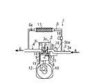
- FIG. 1 is a diagram illustrating a configuration of a condensed water generation control system according to the first embodiment.
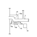
- FIG. 2 is an enlarged view of the configuration around the intake manifold of FIG.
- FIG. 3 is a diagram illustrating the configuration of the condensed water generation control system of the second embodiment.
- the condensed water generation control system 1 is a system including an engine (internal combustion engine) 2, an intake system passage 3, an exhaust system passage 4, and an EGR passage 5. ..
- the piston 7 reciprocally slides in the cylinder 6, so that the fresh air A and the EGR gas Ge are generated in the combustion chamber 9 that is a space surrounded by the cylinder 6, the piston 7, and the cylinder head 8. It is a device for mixing and compressing the mixed gas and the fuel F and burning them.
- the cylinder 6 and the piston 7 are housed inside a cylinder block 10.
- the cylinder block 10 also houses a crankshaft 12 connected to the piston 7 via a connecting rod 11.
- the crankshaft 12 is a device that is rotated by the rotational power converted from the linear movement power of the piston 7 obtained by the combustion reaction in the combustion chamber 9 via the connecting rod 11.
- the cylinder head 8 is a device mounted and connected to the upper surface of the cylinder block 10, and has an intake valve 13, an exhaust valve 14 and a fuel injection device 15 inside thereof.
- Examples of the material of the cylinder head 8 and the cylinder block 10 include a cast iron block or aluminum.
- the intake valve 13 is a device that is opened at least when the mixed gas A + Ge is introduced into the combustion chamber 9 in conjunction with the operation of a valve operating mechanism (not shown) arranged inside the cylinder head 8.
- the exhaust valve 14 is a device that is opened at least when the exhaust gas G is discharged from the combustion chamber 9 in conjunction with the operation of the valve mechanism.
- the fuel injection device 15 is a device that is arranged between the intake valve 13 and the exhaust valve 14 and injects the fuel F into the combustion chamber 9. These devices 13 to 15 are arranged to face the upper surface of the piston 7 via the combustion chamber 9.
- the intake system passage 3 is a passage that communicates with the combustion chamber 9 via the intake valve 13 and introduces the fresh air A into the combustion chamber 9.
- the intake system passage 3 is divided into a first intake passage 3a, a second intake passage 3b, and a third intake passage 3c in order from the upstream side in the flow direction of the fresh air A.
- the first intake passage 3a is a passage where the fresh air A and the EGR gas Ge merge.
- One end of the first intake passage 3a is open to the atmosphere and the other end communicates with one end of the second intake passage 3b.
- a resin is exemplified as the material of the first intake passage 3a.
- the second intake passage 3b is a passage formed as an internal space of the intake manifold 16 connected to the cylinder head 8.
- the third intake passage 3c is a passage formed as an internal space of the cylinder head 8.
- One end of the third intake passage 3c communicates with the other end of the second intake passage 3b, and the other end communicates with the combustion chamber 9 via the intake valve 13.
- the exhaust system passage 4 is a passage that communicates with the combustion chamber 9 via the exhaust valve 14 and discharges most of the exhaust gas G generated by the combustion reaction in the combustion chamber 9 to the atmosphere.
- the EGR passage 5 is a passage that connects the exhaust passage 4 and the intake passage 3 (first intake passage 3a), and is a passage that recirculates a part of the exhaust gas G as EGR gas Ge.
- an EGR cooler 17 and an EGR valve 18 are arranged in order from the upstream side in the flow direction of the EGR gas Ge.
- the EGR cooler 17 is a device that cools the EGR gas Ge by exchanging heat between the EGR gas Ge and a cooling medium (for example, engine cooling water) inside the EGR cooler 17.
- the EGR valve 18 is a device that varies the flow rate of the EGR gas Ge recirculated from the exhaust system passage 4 to the intake system passage 3 according to the opening degree.
- a Peltier element (low temperature forming device) 19 is provided inside the intake manifold 16 (around the second intake passage 3b).
- the Peltier element 19 is an element utilizing the Peltier effect in which a current is caused to flow through a joint portion of two kinds of metals to transfer heat from one metal to the other metal.
- one metal that obtains heat from the periphery of the Peltier element 19 is the heat absorbing portion 19a, and the other metal to which the heat obtained by the heat absorbing portion 19a is transferred is the heat radiating portion 19b. As shown in FIG.
- the Peltier element 19 is arranged on the outer wall surface 16 a of the intake manifold 16 with the wall surface of the second intake passage 3 b as the inner wall surface of the intake manifold 16.
- the heat absorbing portion 19a is arranged at a position facing the inner wall surface 3b of the intake manifold 16, and the heat radiating portion 19b is arranged at a position facing the outside (atmosphere) of the intake manifold 16.
- the heat absorbing portion 19a is arranged on the outer wall surface 16a side by a preset distance d from the inner wall surface 3b facing the heat absorbing portion 19a.
- This set distance d is a distance at which the heat absorbing portion 19a does not suffer heat loss due to the amount of heat of the intake gas A + Ge passing through the second intake passage 3b, and the temperature of the inner wall surface 3b facing the heat absorbing portion 19a can be lowered by the heat absorbing portion 19a.
- the distance is set.
- the set distance is, for example, 3 mm or more and 10 mm or less.
- the heat radiating portion 19b constitutes a part of the outer wall surface 16a of the intake manifold 16, and radiates the amount of heat obtained from the heat absorbing portion 19a to the atmosphere.
- the heat radiating portion 19b may be exposed to the atmosphere, and may be projected or dented with respect to the outer wall surface 16a of the intake manifold 16 around the heat radiating portion 19b. It is preferable that the heat dissipation portion 19b has a fin shape.
- the second intake passage 3b is formed so as to include a portion 3ba having an upward slope in the middle of the flow direction of the mixed gas of the fresh air A and the EGR gas Ge.
- the Peltier element 19 is arranged at a position facing the wall surface on the upstream side of the upslope portion 3ba. When the Peltier element 19 is energized to lower the temperature of the wall surface at the facing position below the temperature of the surrounding wall surface, condensed water is concentratedly generated on the wall surface at the facing position. In order to promote generation of condensed water, it is preferable that the wall surface at the facing position is recessed toward the Peltier element 19 side to increase the surface area of the wall surface.
- the recessed wall surface serves as a condensed water storage structure that stores condensed water.
- the Peltier device 19 is connected to the control device 20.
- the control device 20 is hardware that includes a CPU that performs various types of information processing, an internal storage device that can read and write programs used for performing various types of information processing, and information processing results, and various interfaces.
- This control signal is input to the control device 20 when the ignition key of the vehicle equipped with the engine 2 is turned off.
- the control device 20 controls energization to the Peltier element 19 so that the heat absorbing portion 19a of the Peltier element 19 absorbs heat from the intake air passing through the second intake passage 3b.
- the Peltier element 19 is provided at a position near a part of the wall surface of the intake system passage 3 or the combustion chamber 9 forming this space so that condensed water is generated in the space where the mixed gas A + Ge before combustion passes. It is only necessary to be provided, and the installation position is not limited to that of the first embodiment. Therefore, the Peltier element 19 is adjacent to the intake system passage 3 or the combustion chamber 9 or inside the engine component (piston 7, cylinder head 8, cylinder block 10, intake manifold 16) that covers these devices 3, 9. It is provided.
- the engine component is a member made of a material having a relatively high thermal conductivity such as aluminum as compared with resin
- the engine component is located between the wall surface facing the heat absorbing portion 19a and the condensed water generating portion and the heat absorbing portion 19a. This is preferable because it improves the heat conduction of.
- step S1 it is determined whether or not the ignition key of the vehicle equipped with the engine 2 has been switched from on to off.
- the process proceeds to return and the control using the condensed water generation control system 1 is not performed.
- step S2 if it is determined that the ignition key is switched from on to off (YES), the process proceeds to step S2, and the control signal for this switching is input to the control device 20 in step S2. After the input, go to step S3.
- step S3 the control device 20 performs control to energize the Peltier device 19 for a preset time t using a timer or the like.
- the set time t is set to a time sufficient for the condensed water to be intensively generated on the wall surface of the second intake passage 3b facing the heat absorbing section 19a.
- the set time t is preferably about 30 seconds to 90 seconds.
- the process proceeds to the fourth step S4, and in the fourth step S4, the energization of the Peltier element 19 is terminated, and the control using the condensed water generation control system 1 is terminated.
- step S2A in which the temperature sensor provided in the second intake passage 3b detects the temperature T of the internal space of the second intake passage 3b, and the detected value T You may add step S2B which determines whether it is below the set temperature T1 which was set.
- step S2B if the detected value T is less than or equal to the set temperature T1, the process proceeds to a third step S3, and if the detected value T exceeds the set temperature T1, the process proceeds to return and the condensed water generation control system 1 Is not controlled.
- the set temperature T1 is set to a temperature at which condensed water may be generated.
- condensed water caused by the fresh air A and the EGR gas Ge is generated inside the second intake passage 3b and is stored on the wall surface facing the Peltier element 19. Then, when the engine is started next time, the stored condensed water is blown to the combustion chamber 9 side by the mixed gas A + Ge passing through the second intake passage 3b. The condensed water that has flowed into the combustion chamber 9 evaporates due to the combustion reaction inside the combustion chamber 9.
- the condensed water generation control system 1 of the first embodiment with respect to the intake manifold (engine part) 16 that covers the space (second intake passage) 3b through which the mixed gas A + Ge passes, the position close to the space 3b inside thereof.
- a Peltier element 19 is provided in the. Then, when the ignition key is turned off, the Peltier element 19 is energized so that the temperature of the wall surface forming the space 3b facing the installation position of the Peltier element 19 is made lower than the temperature of the wall surface forming the space 3b around it.
- the condensed water resulting from the moisture contained in the fresh air A and the EGR gas Ge introduced into the engine 2 can be concentratedly generated only in the second intake passage 3b.
- the water concentration in the mixed gas A + Ge can be reduced.
- the generation location of the condensed water it is possible to prevent the generation of the condensed water at other locations where the mixed gas A + Ge passes.
- Peltier element 19 as a low temperature forming device. As a result, when the ignition key is turned off, the temperature of the wall surface of the second intake passage 3b facing the Peltier element 19 can be reliably lowered from the temperature of the wall surface in the vicinity thereof to a temperature at which condensed water can be generated.
- the second intake passage 3b is formed in the middle of the second intake passage 3b so as to have an upward gradient from the upstream side to the downstream side of the mixed gas (intake) A + Ge, and is upstream of the start position of the portion 3ba of the upward gradient.
- a Peltier element 19 is provided so as to face the wall surface of 3b.
- the efficiency of releasing the amount of heat flowing from the heat absorbing portion 19a to the heat dissipation portion 19b to the atmosphere can be improved.
- the condensed water generation control system 1 of the second embodiment will be described with reference to FIG.
- the condensed water generation control system 1 of FIG. 3 uses the high thermal conductivity member 21 instead of the Peltier element 19 as the low-temperature forming device and that the high thermal conductivity member 21 is provided inside the piston 7. It is different from the condensed water generation control system 1 of the embodiment.
- the high thermal conductivity member 21 is a member formed of a material (for example, gold, silver, copper) having a higher thermal conductivity than the material (for example, aluminum) of the piston 7 in which the member 21 is embedded.
- the high thermal conductivity member 21 is a member that automatically lowers in temperature as the temperature inside the combustion chamber 9 decreases, and is not connected to the control device 20.
- the high thermal conductivity member 21 is positioned near a part of the wall surface of the intake system passage 3 or the combustion chamber 9 that forms this space so that condensed water is generated in the space where the mixed gas A + Ge before combustion passes.
- the material of the high thermal conductivity member 21 may be a material having higher thermal conductivity than the material of the wall surface around the wall surface facing the high thermal conductivity member 21.
- the connection between the control device 20 and the high thermal conductivity member 21 becomes unnecessary, so that the layout of the high thermal conductivity member 21 is flexible. Can be higher. Further, the load on the control device 20 can be reduced.
- condensed water generation control system capable of controlling a generation place of condensed water caused by moisture contained in fresh air and EGR gas introduced into an internal combustion engine.
- Condensate generation control system 2
- Engine internal combustion engine
- 3 intake system passage 3a first intake passage 3b second intake passage 3c third intake passage 4
- exhaust system passage 5 EGR passage 6
- cylinder 7 piston 8
- cylinder head 9 combustion chamber 10
- cylinder block 11 connecting rod 12 crankshaft 13 intake valve 14
- Fuel Injector 16 Intake Manifold 16a Outer Wall of Intake Manifold 17
- EGR Cooler 18 EGR Valve 19
- Control Device 21 High Thermal Conductivity Member
Landscapes
- Engineering & Computer Science (AREA)
- Chemical & Material Sciences (AREA)
- Combustion & Propulsion (AREA)
- Mechanical Engineering (AREA)
- General Engineering & Computer Science (AREA)
- Chemical Kinetics & Catalysis (AREA)
- Exhaust-Gas Circulating Devices (AREA)
Abstract
新気とEGRガスの混合気体A+Geが通過する空間に隣接し、または、この空間を覆うエンジン部品に関して、その内部における上記空間に近傍する位置に低温形成装置を設ける。低温形成装置は、エンジン2を備えた車両のイグニッションキーのオフ時に、この位置に対向する上記空間を構成する壁面の温度をその周辺の壁面の温度より低くする装置である。
Description
本開示は、凝縮水発生制御システムに関する。
エンジンの排気流路から吸気流路に還流されるEGRガスから発生する凝縮水を貯留する凝縮水貯留部を備えたEGR装置が提案されている(例えば、特許文献1参照)。
凝縮水は、車両のイグニッションキーのオフ時に、内燃機関に導入される新気及びEGRガスに含まれる水分に起因して発生する場合がある。このとき、凝縮水の発生箇所は内燃機関内に複数点在しており、上記の凝縮水貯留部に限らない。発生箇所の全てを特定することは困難であるため、凝縮水の発生箇所を制御する技術が求められていた。
本開示は、内燃機関に導入される新気及びEGRガスに含まれる水分に起因する凝縮水の発生箇所を制御することができる凝縮水発生制御システムを提供することにある。
上記の目的を達成するための本開示の態様の凝縮水発生制御システムは、凝縮水の発生を制御する凝縮水発生制御システムにおいて、内燃機関に供給される新気とEGRガスの混合気体が通過する空間に隣接し、または、この空間を覆うエンジン部品と、このエンジン部品に関して、その内部における前記空間に近傍する位置に設けられて、前記内燃機関を備えた車両のイグニッションキーのオフ時にこの位置に対向する前記空間を構成する壁面の温度をその周辺の壁面の温度より低くする低温形成装置を備えることを特徴とする。
あるいは、上記の目的を達成するための本開示の態様の凝縮水発生制御システムは、内燃機関と、前記内燃機関に供給される吸気が通過する吸気通路とを有する凝縮水発生制御システムにおいて、前記吸気通路の周辺に設けられ、吸熱部と放熱部とを有する低温形成装置と、前記低温形成装置への通電を制御する制御装置とを有し、前記制御装置は、前記内燃機関を備えた車両のイグニッションキーのオフ時に、前記低温形成装置の吸熱部が吸気より吸熱するように前記低温形成装置への通電を制御することを特徴とする。
本開示によれば、内燃機関に導入される新気及びEGRガスに含まれる水分に起因する凝縮水の発生箇所を制御することができる。
以下、本開示の第1実施形態の凝縮水発生制御システムについて、図面を参照しながら説明する。
図1に例示するように、凝縮水発生制御システム1は、エンジン(内燃機関)2と、吸気系通路3と、排気系通路4と、EGR通路5と、を備えて構成されるシステムである。
エンジン2は、気筒(シリンダ)6内をピストン7が往復摺動することで、気筒6とピストン7とシリンダヘッド8で囲まれた空間である燃焼室9にて、新気AとEGRガスGeの混合気体と燃料Fを混合圧縮して燃焼させる装置である。気筒6及びピストン7はシリンダブロック10の内部に収納される。シリンダブロック10はまた、ピストン7とコンロッド11を介して接続されるクランク軸12を収納する。クランク軸12は、燃焼室9内での燃焼反応により得られたピストン7の直進動力からコンロッド11を介して変換された回転動力により回転する装置である。シリンダヘッド8は、シリンダブロック10の上面に載置及び連結される装置で、その内部に吸気弁13、排気弁14及び燃料噴射装置15を備えている。シリンダヘッド8及びシリンダブロック10の材質としては、鋳鉄ブロック、または、アルミニウムが例示される。吸気弁13は、シリンダヘッド8の内部に配置された図示しない動弁機構の動作に連動して、少なくとも燃焼室9に混合気体A+Geを導入するときに開状態となる装置である。排気弁14は、上記動弁機構の動作に連動して、少なくとも燃焼室9から排気ガスGを排出するときに開状態となる装置である。燃料噴射装置15は、吸気弁13と排気弁14の間に配置されて、燃焼室9に燃料Fを噴射する装置である。これらの装置13~15は、燃焼室9を介してピストン7の上面と対向して配置される。
吸気系通路3は、吸気弁13を介して燃焼室9と連通されて、新気Aを燃焼室9に導入する通路である。吸気系通路3は、新気Aの流れ方向に関して上流側より順に、第1吸気通路3aと、第2吸気通路3bと、第3吸気通路3cと、に分けられる。第1吸気通路3aは、新気AとEGRガスGeの合流がなされる通路である。第1吸気通路3aは、その一端部が大気に開放されて、その他端部が第2吸気通路3bの一端部と連通する。第1吸気通路3aの材質としては、樹脂が例示される。第2吸気通路3bは、シリンダヘッド8に連結される吸気マニホールド16の内部空間として形成される通路である。第2吸気通路3bの一端部は第1吸気通路3aの他端部と連通して、その他端部は第3吸気通路3cの一端部と連通する。吸気マニホールド16の材質としては、アルミニウム、銅、金、銀等の熱伝導率が樹脂に比して比較的高い材質が例示される。第3吸気通路3cは、シリンダヘッド8の内部空間として形成される通路である。第3吸気通路3cの一端部は第2吸気通路3bの他端部と連通して、その他端部は吸気弁13を介して燃焼室9と連通する。
排気系通路4は、排気弁14を介して燃焼室9と連通されて、燃焼室9内での燃焼反応により発生する排気ガスGの大部分を大気に排出する通路である。EGR通路5は、排気系通路4と吸気系通路3(第1吸気通路3a)を連通する通路で、排気ガスGの一部をEGRガスGeとして還流する通路である。EGR通路5には、EGRガスGeの流れ方向に関して上流側より順に、EGRクーラ17と、EGRバルブ18と、が配置される。EGRクーラ17は、その内部でEGRガスGeと冷却媒体(例えばエンジン冷却水)の間で熱交換して、EGRガスGeを冷却する装置である。EGRバルブ18は、その開度に応じて排気系通路4から吸気系通路3に還流されるEGRガスGeの流量を可変させる装置である。
第1実施形態の凝縮水発生制御システム1では、吸気マニホールド16の内部(第2吸気通路3bの周辺)にペルチェ素子(低温形成装置)19を設ける。ペルチェ素子19は、2種類の金属の接合部に電流を流して、一方の金属から他方の金属に熱を移動させるペルチェ効果を利用した素子である。本実施形態では、ペルチェ素子19の周囲から熱量を得る一方の金属を吸熱部19a、吸熱部19aが得た熱量の移動先である他方の金属を放熱部19bとする。図2に示すように、第2吸気通路3bの壁面を吸気マニホールド16の内壁面として、ペルチェ素子19は、吸気マニホールド16の外壁面16aに配置される。吸熱部19aは吸気マニホールド16の内壁面3bに対向する位置に、放熱部19bは吸気マニホールド16の外部(大気)に対向する位置に配置される。吸熱部19aはこの吸熱部19aに対向する内壁面3bより予め設定される設定距離dだけ外壁面16a側に離間して配置される。この設定距離dは、第2吸気通路3bを通過する吸気ガスA+Geの熱量により吸熱部19aが熱損しない距離で、かつ、吸熱部19aにより吸熱部19aに対向する内壁面3bの温度低下が可能な距離に設定される。設定距離として、3mm以上10mm以下が例示される。放熱部19bは吸気マニホールド16の外壁面16aの一部を構成して、吸熱部19aより得た熱量を大気に放出する。放熱部19bは大気に露出していればよく、その周辺の吸気マニホールド16の外壁面16aに対して突出していてもよいし、窪んでいてもよい。放熱部19bはフィン形状にすることが好ましい。
第2吸気通路3bは、新気AとEGRガスGeの混合気体の流れ方向に関して、その途中で上り勾配となる部分3baが含まれるように形成される。ペルチェ素子19は、この上り勾配となる部分3baより上流側の壁面に対向する位置に配置される。ペルチェ素子19への通電によりこの対向位置の壁面の温度がその周囲の壁面の温度より低下したときに、凝縮水はこの対向位置の壁面に集中的に発生する。凝縮水の発生を促すために、この対向位置の壁面をペルチェ素子19側に窪ませてこの壁面の表面積を増加させると好ましい。この窪ませた壁面が凝縮水を貯留する凝縮水蓄積構造となる。
ペルチェ素子19は、制御装置20に接続される。制御装置20は、各種情報処理を行うCPU、その各種情報処理を行うために用いられるプログラムや情報処理結果を読み書き可能な内部記憶装置、及び各種インターフェースなどから構成されるハードウェアである。エンジン2を備えた車両のイグニッションキーがオフになったときに、この制御信号が制御装置20に入力される。制御装置20は、この入力時に、ペルチェ素子19の吸熱部19aが第2吸気通路3bを通過する吸気より吸熱するようにペルチェ素子19への通電を制御する。
なお、ペルチェ素子19は、燃焼前の混合気体A+Geの通過する空間で凝縮水が発生するように、この空間を形成する吸気系通路3または燃焼室9の壁面の一部に近傍する位置に設けられればよく、第1実施形態の設置位置に限定されない。したがって、ペルチェ素子19は、吸気系通路3または燃焼室9に隣接し、または、これらの装置3、9を覆うエンジン部品(ピストン7、シリンダヘッド8、シリンダブロック10、吸気マニホールド16)の内部に設けられる。このエンジン部品は、樹脂に比してアルミニウム等の比較的熱伝導率の高い材質で構成される部材であると、吸熱部19aに対向する凝縮水の発生箇所となる壁面と吸熱部19aの間の熱伝導が良化するため好ましい。特に、ペルチェ素子19を吸気マニホールド16の内部に設けると、ペルチェ素子19と制御装置20を接続する配線の配置が容易となり、また、エンジン2から離間した位置で凝縮水が発生するので好ましい。
第1実施形態の凝縮水発生制御システム1を用いた制御方法について説明する。ステップS1で、エンジン2を備えた車両のイグニッションキーがオンからオフに切り替わったか否かを判定する。ステップS1で、イグニッションキーがオンのままであると判定された場合(NO)にはリターンに進んで凝縮水発生制御システム1を用いた制御は行わない。一方、イグニッションキーがオンからオフに切り替わったと判定された場合(YES)にはステップS2に進み、ステップS2でこの切り替わりの制御信号を制御装置20に入力する。入力後、ステップS3に進む。ステップS3で、制御装置20は、タイマー等を用いてペルチェ素子19を予め設定した設定時間tだけ通電させる制御を行う。設定時間tは、吸熱部19aに対向する第2吸気通路3bの壁面で凝縮水が集中的に発生するのに十分な時間に設定される。例えば、第2吸気通路3bの内部空間の温度Tが60℃程度である場合、設定時間tは30秒~90秒程度にするのが好ましい。第2吸気通路3bの内部空間の温度Tと吸熱部19aの温度の差が大きくなるにつれて、凝縮水の発生量は多くなる。設定時間tが経過後、第4ステップS4に進み、第4ステップS4で、ペルチェ素子19への通電を終了して、凝縮水発生制御システム1を用いた制御を終了する。
なお、第2ステップS2と第3ステップS3の間に、第2吸気通路3bの内部空間の温度Tを第2吸気通路3bに設けた温度センサにより検出するステップS2Aと、この検出値Tが予め設定された設定温度T1以下であるか否かの判定を行うステップS2Bとを加えてもよい。この場合、ステップS2Bにて、検出値Tが設定温度T1以下である場合には第3ステップS3に進み、検出値Tが設定温度T1を上回る場合にはリターンに進んで凝縮水発生制御システム1を用いた制御は行わない。設定温度T1は、凝縮水の発生が懸念される程度の温度に設定される。
ペルチェ素子19への通電により第2吸気通路3bの内部に、新気A及びEGRガスGeに起因した凝縮水が発生して、ペルチェ素子19に対向する壁面に貯留する。そして、次回のエンジン始動時にこの貯留した凝縮水は第2吸気通路3bを通過する混合気体A+Geにより燃焼室9側に吹き飛ばされる。燃焼室9に流入した凝縮水は燃焼室9の内部での燃焼反応により蒸発する。
以上により、第1実施形態の凝縮水発生制御システム1では、混合気体A+Geが通過する空間(第2吸気通路)3bを覆う吸気マニホールド(エンジン部品)16に関して、その内部における空間3bに近傍する位置にペルチェ素子19を設ける。そして、イグニッションキーのオフ時に、ペルチェ素子19に通電して、ペルチェ素子19の設置位置に対向する空間3bを構成する壁面の温度をその周辺の空間3bを構成する壁面の温度より低くする。これにより、エンジン2に導入される新気A及びEGRガスGeに含まれる水分に起因する凝縮水を第2吸気通路3bの内部に限定して集中的に発生させることができる。また、第2吸気通路3bの内部に凝縮水を集中的に発生させることで、混合気体A+Ge中の水分濃度を低下させることができる。言い換えれば、凝縮水の発生箇所を制御することで、混合気体A+Geが通過する他の箇所での凝縮水の発生を防止できる。
低温形成装置としてペルチェ素子19を用いる。これにより、イグニッションキーのオフ時にペルチェ素子19に対向する第2吸気通路3bの壁面の温度をその周辺の壁面の温度より凝縮水が発生可能な温度まで確実に低温化させることができる。
第2吸気通路3bの途中で混合気体(吸気)A+Geの上流側から下流側に向かって上り勾配となるように形成して、この上り勾配の部分3baの開始位置より上流側の第2吸気通路3bの壁面に対向してペルチェ素子19を設ける。これにより、第2吸気通路3bを混合気体A+Geが通過しない限り、イグニッションキーのオフ時に貯留した凝縮水を燃焼室9側に流出させることなくこの壁面に留まらせることができる。
ペルチェ素子19の放熱部19bの形状がフィン形状であると、吸熱部19aから放熱部19bに流れる熱量の大気への放出効率を向上させることができる。
第2実施形態の凝縮水発生制御システム1について図3を参照しながら説明する。図3の凝縮水発生制御システム1は、低温形成装置としてペルチェ素子19ではなく高熱伝導率部材21を用いる点と、この高熱伝導率部材21をピストン7の内部に設けている点で第1実施形態の凝縮水発生制御システム1とは異なる。高熱伝導率部材21は、この部材21が埋め込まれるピストン7の材質(例えばアルミニウム)より熱伝導率の高い材質(例えば金、銀、銅)で形成される部材である。高熱伝導率部材21は、燃焼室9内の温度の低温化に伴い自動的に低温化する部材で、制御装置20に接続されない。
なお、高熱伝導率部材21は、燃焼前の混合気体A+Geの通過する空間で凝縮水が発生するように、この空間を形成する吸気系通路3または燃焼室9の壁面の一部に近傍する位置に設けられればよく、第2実施形態の設置位置に限定されない。したがって、高熱伝導率部材21の材質は、高熱伝導率部材21に対向する壁面の周辺の壁面の材質より熱伝導率の高い材質であればよい。
第2実施形態のように、低温形成装置として高熱伝導率部材21を用いると、制御装置20と高熱伝導率部材21の接続が不要となるので、高熱伝導率部材21の配置レイアウトの自由度を高くすることができる。また、制御装置20の負担を軽減することができる。
本出願は、2018年11月14日付で出願された日本国特許出願(特願2018-214090)に基づくものであり、その内容はここに参照として取り込まれる。
本開示によれば、内燃機関に導入される新気及びEGRガスに含まれる水分に起因する凝縮水の発生箇所を制御することができる凝縮水発生制御システムを提供できるという点において有用である。
1 凝縮水発生制御システム
2 エンジン(内燃機関)
3 吸気系通路
3a 第1吸気通路
3b 第2吸気通路
3c 第3吸気通路
4 排気系通路
5 EGR通路
6 気筒
7 ピストン
8 シリンダヘッド
9 燃焼室
10 シリンダブロック
11 コンロッド
12 クランク軸
13 吸気弁
14 排気弁
15 燃料噴射装置
16 吸気マニホールド
16a 吸気マニホールドの外壁面
17 EGRクーラ
18 EGR弁
19 ペルチェ素子
19a 吸熱部
19b 放熱部
20 制御装置
21 高熱伝導率部材
2 エンジン(内燃機関)
3 吸気系通路
3a 第1吸気通路
3b 第2吸気通路
3c 第3吸気通路
4 排気系通路
5 EGR通路
6 気筒
7 ピストン
8 シリンダヘッド
9 燃焼室
10 シリンダブロック
11 コンロッド
12 クランク軸
13 吸気弁
14 排気弁
15 燃料噴射装置
16 吸気マニホールド
16a 吸気マニホールドの外壁面
17 EGRクーラ
18 EGR弁
19 ペルチェ素子
19a 吸熱部
19b 放熱部
20 制御装置
21 高熱伝導率部材
Claims (5)
- 凝縮水の発生を制御する凝縮水発生制御システムにおいて、
内燃機関に供給される新気とEGRガスの混合気体が通過する空間に隣接し、または、この空間を覆うエンジン部品と、
このエンジン部品に関して、その内部における前記空間に近傍する位置に設けられて、前記内燃機関を備えた車両のイグニッションキーのオフ時にこの位置に対向する前記空間を構成する壁面の温度をその周辺の壁面の温度より低くする低温形成装置を備えることを特徴とする凝縮水発生制御システム。 - 前記低温形成装置がペルチェ素子であることを特徴とする請求項1に記載の凝縮水発生制御システム。
- 前記低温形成装置が、前記周辺の壁面の材質より熱伝導率の高い材質で形成された高熱伝導率部材であることを特徴とする請求項1に記載の凝縮水発生制御システム。
- 前記エンジン部品が吸気マニホールドであり、この吸気マニホールドの内部における前記空間を構成する吸気通路に関して、その途中で吸気の上流側から下流側に向かって上り勾配となるように形成して、この上り勾配の開始位置より上流側の壁面に対向する前記吸気マニホールドの内部位置に低温形成装置及び凝縮水蓄積構造を設けることを特徴とする請求項1~3のいずれか1項に記載の凝縮水発生制御システム。
- 内燃機関と、前記内燃機関に供給される吸気が通過する吸気通路とを有する凝縮水発生制御システムにおいて、
前記吸気通路の周辺に設けられ、吸熱部と放熱部とを有する低温形成装置と、前記低温形成装置への通電を制御する制御装置とを有し、
前記制御装置は、前記内燃機関を備えた車両のイグニッションキーのオフ時に、前記低温形成装置の吸熱部が吸気より吸熱するように前記低温形成装置への通電を制御することを特徴とする凝縮水発生制御システム。
Applications Claiming Priority (2)
| Application Number | Priority Date | Filing Date | Title |
|---|---|---|---|
| JP2018214090A JP2020084762A (ja) | 2018-11-14 | 2018-11-14 | 凝縮水発生制御システム |
| JP2018-214090 | 2018-11-14 |
Publications (1)
| Publication Number | Publication Date |
|---|---|
| WO2020100864A1 true WO2020100864A1 (ja) | 2020-05-22 |
Family
ID=70731112
Family Applications (1)
| Application Number | Title | Priority Date | Filing Date |
|---|---|---|---|
| PCT/JP2019/044270 Ceased WO2020100864A1 (ja) | 2018-11-14 | 2019-11-12 | 凝縮水発生制御システム |
Country Status (2)
| Country | Link |
|---|---|
| JP (1) | JP2020084762A (ja) |
| WO (1) | WO2020100864A1 (ja) |
Citations (4)
| Publication number | Priority date | Publication date | Assignee | Title |
|---|---|---|---|---|
| JP2004068608A (ja) * | 2002-08-01 | 2004-03-04 | Toyota Motor Corp | 内燃機関の排ガス再循環装置 |
| JP2014185618A (ja) * | 2013-03-25 | 2014-10-02 | Toyota Motor Corp | 内燃機関の排気還流装置 |
| JP2017014953A (ja) * | 2015-06-30 | 2017-01-19 | 三菱自動車工業株式会社 | インテークマニホールド |
| JP2017115588A (ja) * | 2015-12-21 | 2017-06-29 | いすゞ自動車株式会社 | 内燃機関のピストン |
-
2018
- 2018-11-14 JP JP2018214090A patent/JP2020084762A/ja active Pending
-
2019
- 2019-11-12 WO PCT/JP2019/044270 patent/WO2020100864A1/ja not_active Ceased
Patent Citations (4)
| Publication number | Priority date | Publication date | Assignee | Title |
|---|---|---|---|---|
| JP2004068608A (ja) * | 2002-08-01 | 2004-03-04 | Toyota Motor Corp | 内燃機関の排ガス再循環装置 |
| JP2014185618A (ja) * | 2013-03-25 | 2014-10-02 | Toyota Motor Corp | 内燃機関の排気還流装置 |
| JP2017014953A (ja) * | 2015-06-30 | 2017-01-19 | 三菱自動車工業株式会社 | インテークマニホールド |
| JP2017115588A (ja) * | 2015-12-21 | 2017-06-29 | いすゞ自動車株式会社 | 内燃機関のピストン |
Also Published As
| Publication number | Publication date |
|---|---|
| JP2020084762A (ja) | 2020-06-04 |
Similar Documents
| Publication | Publication Date | Title |
|---|---|---|
| JP4629142B2 (ja) | 過給気内燃機関の排気の再循環のための装置 | |
| US7527045B2 (en) | Evaporative emission control system and method for internal combustion engine having a microcondenser device | |
| JP4571673B2 (ja) | 車輌の冷却装置 | |
| US8646671B2 (en) | Combustion chamber and cooling system for fastener-driving tools | |
| JP5172017B2 (ja) | 過給式内燃機関用の低温冷却システムにおける装置 | |
| ATE515634T1 (de) | Abgasrückführsystem für eine verbrennungskraftmaschine | |
| US9752540B2 (en) | Integrated cooling system and control method thereof | |
| RU2156364C2 (ru) | Система охлаждения с электронным управлением автомобильного двигателя | |
| RU142014U1 (ru) | Система турбонагнетателя с регулятором давления наддува | |
| KR101542990B1 (ko) | 이지알쿨러로 냉각수를 선택적으로 공급하는 냉각수 제어밸브 | |
| JP5928407B2 (ja) | 内燃機関の燃料噴射装置 | |
| JP2020084762A (ja) | 凝縮水発生制御システム | |
| JP2004068608A (ja) | 内燃機関の排ガス再循環装置 | |
| JP2006348793A (ja) | 内燃機関の排気還流装置 | |
| US20170002775A1 (en) | Air intake structure for engine | |
| JP2022023773A (ja) | Egrシステム | |
| JP6380239B2 (ja) | Egr装置 | |
| EP2481908A1 (en) | Exhaust gas recirculation system | |
| JP7122949B2 (ja) | 流量制御装置、これを含む冷却システムおよびその制御方法 | |
| WO2022024578A1 (ja) | Egrシステム | |
| JPH04252850A (ja) | 内燃機関用排気ガス還流装置 | |
| JP6911363B2 (ja) | 内燃機関の冷却装置 | |
| KR102552021B1 (ko) | 냉각 시스템의 제어 방법 | |
| KR20070080672A (ko) | 차량용 erg쿨러 | |
| JP2019002337A (ja) | エンジンの吸気方法および吸気装置 |
Legal Events
| Date | Code | Title | Description |
|---|---|---|---|
| 121 | Ep: the epo has been informed by wipo that ep was designated in this application |
Ref document number: 19883963 Country of ref document: EP Kind code of ref document: A1 |
|
| NENP | Non-entry into the national phase |
Ref country code: DE |
|
| 122 | Ep: pct application non-entry in european phase |
Ref document number: 19883963 Country of ref document: EP Kind code of ref document: A1 |