WO2020100767A1 - 熱交換器及び熱交換器のデフロスト方法 - Google Patents
熱交換器及び熱交換器のデフロスト方法 Download PDFInfo
- Publication number
- WO2020100767A1 WO2020100767A1 PCT/JP2019/043986 JP2019043986W WO2020100767A1 WO 2020100767 A1 WO2020100767 A1 WO 2020100767A1 JP 2019043986 W JP2019043986 W JP 2019043986W WO 2020100767 A1 WO2020100767 A1 WO 2020100767A1
- Authority
- WO
- WIPO (PCT)
- Prior art keywords
- heat transfer
- defrost
- transfer tube
- cooling medium
- passage
- Prior art date
- Legal status (The legal status is an assumption and is not a legal conclusion. Google has not performed a legal analysis and makes no representation as to the accuracy of the status listed.)
- Ceased
Links
Images

Classifications
-
- F—MECHANICAL ENGINEERING; LIGHTING; HEATING; WEAPONS; BLASTING
- F25—REFRIGERATION OR COOLING; COMBINED HEATING AND REFRIGERATION SYSTEMS; HEAT PUMP SYSTEMS; MANUFACTURE OR STORAGE OF ICE; LIQUEFACTION SOLIDIFICATION OF GASES
- F25B—REFRIGERATION MACHINES, PLANTS OR SYSTEMS; COMBINED HEATING AND REFRIGERATION SYSTEMS; HEAT PUMP SYSTEMS
- F25B47/00—Arrangements for preventing or removing deposits or corrosion, not provided for in another subclass
- F25B47/02—Defrosting cycles
-
- F—MECHANICAL ENGINEERING; LIGHTING; HEATING; WEAPONS; BLASTING
- F25—REFRIGERATION OR COOLING; COMBINED HEATING AND REFRIGERATION SYSTEMS; HEAT PUMP SYSTEMS; MANUFACTURE OR STORAGE OF ICE; LIQUEFACTION SOLIDIFICATION OF GASES
- F25D—REFRIGERATORS; COLD ROOMS; ICE-BOXES; COOLING OR FREEZING APPARATUS NOT OTHERWISE PROVIDED FOR
- F25D21/00—Defrosting; Preventing frosting; Removing condensed or defrost water
- F25D21/06—Removing frost
-
- F—MECHANICAL ENGINEERING; LIGHTING; HEATING; WEAPONS; BLASTING
- F25—REFRIGERATION OR COOLING; COMBINED HEATING AND REFRIGERATION SYSTEMS; HEAT PUMP SYSTEMS; MANUFACTURE OR STORAGE OF ICE; LIQUEFACTION SOLIDIFICATION OF GASES
- F25D—REFRIGERATORS; COLD ROOMS; ICE-BOXES; COOLING OR FREEZING APPARATUS NOT OTHERWISE PROVIDED FOR
- F25D21/00—Defrosting; Preventing frosting; Removing condensed or defrost water
- F25D21/06—Removing frost
- F25D21/12—Removing frost by hot-fluid circulating system separate from the refrigerant system
-
- F—MECHANICAL ENGINEERING; LIGHTING; HEATING; WEAPONS; BLASTING
- F28—HEAT EXCHANGE IN GENERAL
- F28F—DETAILS OF HEAT-EXCHANGE AND HEAT-TRANSFER APPARATUS, OF GENERAL APPLICATION
- F28F17/00—Removing ice or water from heat-exchange apparatus
-
- F—MECHANICAL ENGINEERING; LIGHTING; HEATING; WEAPONS; BLASTING
- F28—HEAT EXCHANGE IN GENERAL
- F28F—DETAILS OF HEAT-EXCHANGE AND HEAT-TRANSFER APPARATUS, OF GENERAL APPLICATION
- F28F9/00—Casings; Header boxes; Auxiliary supports for elements; Auxiliary members within casings
- F28F9/26—Arrangements for connecting different sections of heat-exchange elements, e.g. of radiators
Definitions
- the present disclosure relates to a heat exchanger and a defrosting method for the heat exchanger.
- Natural refrigerants such as NH 3 and CO 2 have been reviewed as refrigerants for refrigeration equipment used for freezing foods and the like. Therefore, a refrigerating apparatus is widely used in which NH 3 which has high cooling performance but is toxic is used as a primary refrigerant and nontoxic and odorless CO 2 is used as a secondary refrigerant.
- CO 2 cooled by NH 3 is sent to a heat exchanger such as an air cooler provided in a freezer or a freezer to cool the air in the freezer (Patent Document 1).
- frost adheres to the heat transfer tube provided in the air cooler, and the heat transfer coefficient efficiency decreases, so it is necessary to periodically suspend the operation of the refrigeration system and perform defrosting.
- the present inventors have previously proposed a defrosting method of sublimating and removing frost attached to fins and heat transfer tubes (Patent Document 2).
- Patent Document 2 frost is sublimated and scattered on the air flow, so that no melt water is generated. Therefore, there is an advantage that the work of removing the melted water from the heat exchanger becomes unnecessary and defrosting can be performed while the operation of the air cooler is continued.
- a plurality of air coolers are arranged in parallel in a freezer to perform defrosting of a frosted heat exchanger, while other heat exchangers are defrosted.
- the operation is continued.
- the degree of frosting differs depending on the position of the heat transfer tube inside the heat exchanger.
- the growth of frost is accelerated due to the high heat transfer coefficient. This is mainly due to the accumulation and stacking due to the mist (liquid and solid) deposited in the air colliding with the inlet side due to the inertial force. Therefore, if the defrosting is uniformly performed for each heat exchanger without considering the position of the heat transfer tubes in the heat exchanger, it is inevitable that the operating rate of the heat exchanger is lowered due to the defrosting.
- Patent Document 2 the heat transfer tube of the heat exchanger is divided into a plurality of regions, and while performing the defrosting in some regions, the cooling operation is performed in the other regions, thereby performing the defrosting while continuing the cooling operation. It is described to enable. However, Patent Document 2 only discloses the idea of performing cooling operation in other regions while performing defrosting in some regions, and considers the position of the heat transfer tubes inside the heat exchanger. The defrosting method described above and the structure of the flow path and the piping for performing this are not disclosed.
- An embodiment is intended to suppress a decrease in the operating rate of the heat exchanger due to the defrosting by performing the defrosting in consideration of the location of the heat transfer tubes inside the heat exchanger.
- the heat exchanger is A gas flow path through which the cooled gas flows, A plurality of heat transfer tube groups arranged in the same gas flow path, A cooling medium inlet channel for supplying a cooling medium to the plurality of heat transfer tube groups; An inlet branch passage branched from the cooling medium inlet passage and connected to the inlet of each heat transfer tube group, A cooling medium outlet flow path for flowing the cooling medium flowing out from the plurality of heat transfer tube groups, An outlet branch passage branched from the cooling medium outlet passage and connected to the outlet of each heat transfer tube group, A defrost channel for supplying a defrost fluid to the plurality of heat transfer tube groups, A defrost branch passage communicating with the defrost passage and connected to the inlet or the outlet of each heat transfer tube group, A plurality of defrost valves respectively provided in the defrost branch passages of the plurality of heat transfer tube groups, Equipped with The plurality of defrost valves opens the defrost valve corresponding to a first heat transfer tube
- the heat transfer tube group consists of one or more heat transfer tubes.
- the defrost passage can be easily and selectively switched to one or more of the plurality of heat transfer tube groups simply by opening and closing the defrost valve.
- defrosting can be selectively performed for each heat transfer tube group.
- the heat transfer tube group on the upstream side inside the heat exchanger is more likely to be frosted than the other heat transfer tube groups, so that the defrost frequency of the heat transfer tube group on the upstream side can be increased. Therefore, since the defrost frequency can be selected for each heat transfer tube group according to the degree of frost growth, it is possible to suppress a decrease in the operating rate of the heat exchanger due to defrosting.
- the defrost branch is connected to the outlet of each heat transfer tube group.
- the defrost fluid can be supplied to the heat transfer tube group from the outlet side of the heat transfer tube group.
- the cooling medium supplied to the heat transfer tube group is supplied as a liquid or a two-phase flow of a liquid and a gas and exchanges heat with the gas to be cooled to change into a gas.
- the defrosting fluid is supplied to the heat transfer tube group as a gas and exchanges heat with the heat transfer tube to change into a liquid phase.
- the heat transfer tubes are arranged in the up-down direction, the cooling medium is supplied from below during the cooling operation, and the cooling medium is vaporized by heat exchange with the heat transfer tubes and undergoes a phase change into gas, and is allowed to flow out from above.
- the defrosting fluid is supplied to the heat transfer tube from above during defrosting, the defrosting fluid is condensed by heat exchange with the heat transfer tube and changes into a liquid phase to flow down. In this way, the cooling medium and the defrosting fluid can be easily discharged from the heat transfer tube after heat exchange.
- a defrost fluid state adjusting unit is provided in the defrost flow path and is capable of adjusting the state of the defrost fluid to a target state.
- the "defrost fluid state adjusting section” is an adjusting section for controlling the temperature, pressure, etc. of the defrost fluid by heating, a pressure control valve, etc.
- the target state is the defrost fluid state. Is supplied to the heat transfer tube group that is the target of defrosting, the frost adhesion surface temperature can be maintained below 0 ° C. and above the temperature of the gas to be cooled.
- the defrost fluid condition adjusting unit when the defrost fluid condition adjusting unit supplies each heat transfer tube group, the frost adhesion surface temperature is maintained below 0 ° C. and higher than the temperature of the gas to be cooled.
- the defrosting fluid adjusted so that it can be supplied to the heat transfer tube group can perform defrosting. This enables sublimation defrost without the generation of molten water. Therefore, the work of removing the molten water from the heat exchanger becomes unnecessary, and defrost can be performed in some heat transfer tube groups while continuing the cooling operation in other heat transfer tube groups.
- the defrost fluid condition controller includes a pressure control valve provided in the defrost passage. According to the configuration of (4), by controlling the pressure of the defrost fluid by the pressure control valve, the state of the defrost fluid is controlled, and when the defrost fluid is supplied, the frost adhesion surface temperature is kept below 0 ° C. In addition, the temperature can be adjusted to be higher than the temperature of the gas to be cooled. This allows sublimation defrost.
- the defrost fluid condition adjusting unit includes a heating unit provided in the defrost flow path.
- the state of the defrost fluid is controlled by the heating unit, and when the defrost fluid is supplied, the surface temperature of the frost is adjusted to less than 0 ° C. and higher than the temperature of the gas to be cooled. it can. This allows sublimation defrost.
- the defrost fluid condition adjusting unit includes an external heat source heat exchanger provided in the defrost flow path to exchange heat with the external heat source.
- the state of the defrost fluid is controlled by the external heat source heat exchanger, and when the defrost fluid is supplied, the frost adhesion surface temperature is lower than 0 ° C. and higher than the temperature of the gas to be cooled. Can be adjusted to temperature. This allows sublimation defrost.
- the defrost branch passages are provided at the inlet and the outlet of each heat transfer tube group, and the defrost branch passages provided at the inlet are provided with a pressure reducing portion, and the cooling medium inlet passage or the cooling medium outlet flow is provided. Connected to the road.
- the defrost fluid after being defrosted in the heat transfer tube group that performs defrosting is decompressed by the decompression unit and returned to the low-pressure cooling medium inlet passage or the cooling medium outlet passage. Therefore, the defrost fluid can be returned to the cooling medium passage without disturbing the flow of the cooling medium in the cooling medium inlet passage or the cooling medium outlet passage. Therefore, the cooling operation can be stably continued in another heat transfer tube group.
- a refrigerant circuit in which the refrigerant circulates A refrigeration cycle constituent device provided in the refrigerant circuit, Equipped with a refrigerator having The cooling medium inlet passage, the cooling medium outlet passage, and the defrost passage are each connected to the refrigerant circuit.
- the refrigerant circulating in the refrigerant circuit can be replenished to the defrost passage as the defrost fluid.
- the refrigeration cycle component device includes a compressor that compresses the refrigerant, a condenser that condenses the refrigerant discharged from the compressor, and a receiver that stores the refrigerant condensed by the condenser,
- the defrost channel is connected to the gas phase of the receiver.
- the refrigeration cycle component device includes a compressor that compresses the refrigerant, a condenser that condenses the refrigerant discharged from the compressor, and a receiver that stores the refrigerant condensed by the condenser,
- the defrost channel is connected to the outlet side of the compressor. According to the above configuration (10), the retained heat of the high-temperature and high-pressure cooling gas on the compressor outlet side can be used as a defrost heat source.
- a primary circuit in which the refrigerant circulates A refrigeration cycle constituent device including an evaporator provided in the primary circuit; A secondary circuit in which the medium to be cooled is circulated, and the medium to be cooled is heat-exchanged with the refrigerant in the evaporator; Is composed of The cooling medium inlet channel, the cooling medium outlet channel and the defrost channel are connected to the secondary circuit.
- the refrigerant circulating in the secondary circuit can be replenished to the defrost passage as a defrost fluid.
- a defrosting method for a heat exchanger is A gas flow path through which the cooled gas flows, A plurality of heat transfer tube groups arranged in the same gas flow path, A cooling medium inlet channel for supplying a cooling medium to the plurality of heat transfer tube groups; An inlet branch passage branched from the cooling medium inlet passage and connected to the inlet of each heat transfer tube group, A cooling medium outlet flow path for flowing the cooling medium flowing out from the plurality of heat transfer tube groups, An outlet branch passage branched from the cooling medium outlet passage and connected to the outlet of each heat transfer tube group, A defrost channel for supplying a defrost fluid to the plurality of heat transfer tube groups, A defrost branch connected to the inlet or the outlet of each heat transfer tube group; A plurality of defrost valves respectively provided in the defrost branch passages of the plurality of heat transfer tube groups, Equipped with The plurality of defrost valves opens the defrost valve corresponding to a first heat transfer tube group that
- the heat exchange configured to selectively defrost the first heat transfer tube group while maintaining the circulation state of the cooling medium to the second heat transfer tube group by closing the defrost valve.
- a defrosting method for vessels A defrost step of selecting one or more heat transfer tube groups as the defrosting target tubes from the plurality of heat transfer tube groups and defrosting each of the one or more heat transfer tube groups is provided.
- defrosting in the defrosting step, defrosting can be performed by appropriately selecting the defrosting order for each one or more heat transfer tube groups.
- the defrost frequency of the heat transfer tube group where frost is likely to grow is increased, and the defrost frequency of the heat transfer tube group where frost is not likely to grow is decreased, so that it is possible to suppress a decrease in the operating rate of the heat exchanger due to defrosting. ..
- the heat transfer tube group selected as the defrosting target tube is supplied with the defrosted fluid whose temperature is adjusted so as to maintain the frost attachment surface temperature below 0 ° C. and higher than the temperature of the gas to be cooled.
- the frost adhesion surface temperature can be maintained at a temperature lower than 0 ° C. and higher than the temperature of the cooled gas. Sublimation defrost becomes possible by supplying the defrost fluid adjusted to the ready state.
- the defrosting frequency can be selected for each heat transfer tube group in consideration of the arrangement locations of the plurality of heat transfer tube groups forming the heat exchanger, so that defrosting can be performed efficiently, and As a result, it is possible to suppress a decrease in the operating rate of the heat exchanger due to the defrosting.
- expressions such as “identical”, “equal”, and “homogeneous” that indicate that they are in the same state are not limited to a state in which they are exactly equal to each other. It also represents the existing state.
- the representation of a shape such as a quadrangle or a cylinder does not only represent a shape such as a quadrangle or a cylinder in a geometrically strict sense, but also an uneven portion or a chamfer within a range in which the same effect can be obtained.
- the shape including parts and the like is also shown.
- the expressions “comprising”, “comprising”, “comprising”, “including”, or “having” one element are not exclusive expressions excluding the existence of other elements.
- FIG. 1 is a perspective view schematically showing a heat exchanger according to one embodiment.
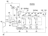
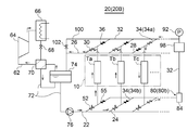
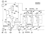
- 2 to 4 are system diagrams of a refrigerator including a heat exchanger according to some embodiments.
- the heat exchanger 10 shown in FIG. 1 is an air cooler that is provided in, for example, a freezer or a freezer and cools a space inside the freezer or a space inside a housing of the freezer. Inside the casing 12 of the heat exchanger 10, a flow path a through which the air to be cooled flows is formed.
- the front surface and the rear surface of the casing 12 are open, and the flow passage a of the cooled air that flows in from the front surface of the casing 12 and flows out from the rear surface by the operation of the fan 14 (14a, 14b, 14c) and the like. Is formed.
- a plurality of heat transfer tubes 16 are provided in the air flow path a.
- the heat transfer tubes 16 are divided into a plurality of heat transfer tube groups Ta, Tb, Tc, ... And the cooling medium supplied during the normal cooling operation and the defrost fluid supplied during the defrost operation are provided for each heat transfer tube group. It is configured to be switched and supplied.
- the heat transfer tube group includes one or a plurality of heat transfer tubes 16, and the plurality of heat transfer tube groups are arranged in the same air flow path a.
- the heat transfer tube 16 is shown only in the upper area Fa in the casing 12, and the heat transfer tube 16 is omitted in the other middle area Tb and lower area Tc.
- the heat transfer tube groups are also arranged in Tb and the lower area Tc, and like the heat transfer tube groups Ta, Tb, and Tc in the upper area Fa, a plurality of heat transfer tube groups also exist in the middle area Tb and the lower area Tc.
- the air flow path a includes a plurality of flow path regions Fa, Fb, and Fc arranged in the direction of arrow c.
- the flow channel system for supplying the cooling medium to the heat transfer tube group during the cooling operation is the cooling medium inlet channel 22 and the cooling medium inlet channel 22. And an inlet branch passage 24 connected to the inlet of each heat transfer tube group.
- the cooling medium is supplied from the cooling medium inlet channel 22 to each heat transfer tube group via each inlet branch passage 24.
- the flow path system for discharging the cooling medium from each heat transfer tube group includes a cooling medium outlet flow path 26 and an outlet branch path 28 branched from the cooling medium outlet flow path and connected to the outlet of each heat transfer tube group.
- the cooling medium that has cooled the air to be cooled in each heat transfer tube group is discharged from each heat transfer tube group and discharged from each outlet branch passage 28 to the cooling medium outlet flow path 26.
- the flow path system that supplies the defrost fluid to each heat transfer tube group during the defrost operation is in communication with the defrost flow path 32 and the defrost flow path 32, and is connected to the inlet or the outlet of each heat transfer tube group 34 (34a). , 34b), and the defrost fluid is supplied from the defrost channel 32 to each heat transfer tube group via each defrost branch channel 34.
- a cooling medium valve 30 is provided in each outlet branch passage 28, and a defrost valve 36 is provided in each defrost branch passage 34. By opening and closing these valves, a flow path of the cooling medium or defrost fluid passing through the heat transfer tube group is formed. It is formed.
- the defrost valve 36 corresponding to the heat transfer tube group (for example, Ta in FIGS. 2 and 4 and Tc in FIG. 3) that is a part of the plurality of heat transfer tube groups Ta, Tb, Tc, .... (In addition, the corresponding solenoid valve 55 in FIG. 3) is opened, and the corresponding cooling medium valve 30 is closed, and the defrost valve 36 corresponding to the remaining heat transfer tube group (in addition, the corresponding solenoid valve 55 in FIG. 3). Is closed and the corresponding cooling medium valve 30 is opened.
- the defrost fluid is a cooling medium supplied to the heat transfer tube 16 during the cooling operation.
- the defrost passage constituted by the defrost passage 32 and the defrost branch passage 34 can be simplified simply by opening / closing the cooling medium valve 30 and the defrost valve 36 (in addition to the electromagnetic valve 55 in FIG. 3).
- one or more of the plurality of heat transfer tube groups can be selectively switched.
- defrosting can be selectively performed for each heat transfer tube group.
- the heat transfer tube group on the upstream side inside the heat exchanger 10 is more likely to be frosted than the other heat transfer tube groups, so that the defrost frequency of the heat transfer tube group on the upstream side can be increased. Therefore, since the defrost frequency can be selected for each heat transfer tube group according to the degree of frost growth, it is possible to suppress a decrease in the operating rate of the heat exchanger due to defrosting.
- the plurality of heat transfer tubes 16 are orthogonal to the flow direction of the air to be cooled (hereinafter, also simply referred to as “flow direction”) (width direction). . Extending in the direction of arrow b), arranged in a plurality of rows at intervals in the flow direction, and arranged in a plurality of stages in a direction orthogonal to the flow direction and the width direction (vertical direction; direction of arrow c).
- the fan 14 is provided on the downstream side in the flow direction of the casing 12, but may be provided on the upstream side in the flow direction of the casing 12 to be an extrusion type fan.
- the defrost branch path 34 is connected to the outlet of each heat transfer tube group.
- the defrost fluid can be supplied to the heat transfer tube group from the outlet side of the heat transfer tube group.
- the cooling medium supplied to the heat transfer tube group is supplied as a liquid or a two-phase flow of a liquid and a gas and exchanges heat with the gas to be cooled to change into a gas.
- the defrosting fluid is supplied to the heat transfer tube group as a gas and exchanges heat with the heat transfer tube 16 to change into a liquid phase.
- the cooling medium undergoes a phase change into gas and flows out from above.
- the defrosting fluid is supplied from above to the heat transfer tube at the time of defrosting, the defrosting fluid undergoes a phase change into a liquid and is made to flow down. In this way, both the cooling medium and the defrost fluid can be easily discharged from the heat transfer tube 16 after heat exchange in the heat transfer tube 16.
- the refrigerator 20 (20A) includes a refrigerant circuit 42 in which a refrigerant circulates, and a refrigeration cycle constituent device provided in the refrigerant circuit 42.
- the cooling medium inlet channel 22, the cooling medium outlet channel 26, and the defrost channel 32 are connected to the refrigerant circuit 42, respectively.
- the refrigerant circulating in the refrigerant circuit 42 can be replenished to the defrost flow passage 32 as a defrost fluid.
- the refrigeration cycle components include a compressor 44, a condenser 46 and an expansion valve 48.
- the refrigerant circulating in the refrigerant circuit 42 is, for example, NH 3 , R-404A, and CO 2 , and the refrigerant gas is compressed by the compressor 44 and cooled by the cooling medium in the condenser 46 to be liquefied.
- the liquefied refrigerant liquid is decompressed through the expansion valve 48, then is supplied to the heat transfer pipe 16 of the heat exchanger 10 through the cooling medium inlet passage 22 and the inlet branch passage 24, and is transferred to the heat transfer pipe 16 of the heat exchanger 10. Cooling air is cooled and vaporized.
- the refrigerant gas vaporized in the heat transfer tube 16 returns to the refrigerant circuit 42 via the outlet branch passage 28 and the cooling medium outlet passage 26.
- a receiver 50 that stores the refrigerant condensed in the condenser 46 is provided in the refrigerant circuit 42, and the defrost flow channel 32 is connected to the gas phase of the receiver 50.
- the defrost flow path 32 is connected to the gas phase of the receiver 50, at the time of defrost, the high temperature and high pressure refrigerant gas from the receiver 50 to the condenser downstream side is efficiently transferred to the heat transfer tubes of the heat exchanger 10. Can supply to groups.
- the defrost channel 32 is connected to the outlet side of the compressor 44.
- a branch line 114 that branches from the refrigerant circuit 42 is provided, and the branch line 114 is connected to the defrost flow path 32.
- the branch line 114 is provided with the pressure control valve 116, and by switching the opening and closing of the pressure control valves 90 and 116, the high-temperature and high-pressure refrigerant discharged from the compressor 44 at the time of defrost can be supplied to the defrost flow passage 32.
- the retained heat of the high temperature and high pressure refrigerant on the compressor outlet side can be used as a defrost heat source.
- the refrigerator 20 (20B, 20C) shown in FIGS. 3 and 4 includes a primary circuit 62 in which a refrigerant circulates, a refrigeration cycle constituent device including an evaporator 70 provided in the primary circuit 62, and
- the secondary circuit 72 is configured to circulate the cooling medium and to exchange heat with the refrigerant in the evaporator 70.
- the cooling medium inlet channel 22, the cooling medium outlet channel 26, and the defrost channel 32 are connected to the secondary circuit 72.
- the refrigerant circulating in the secondary circuit 72 can be replenished to the defrost flow passage 32 as a defrost fluid.
- the primary circuit 62 is provided with a compressor 64, a condenser 66, and an expansion valve 68 as other refrigeration cycle components.
- the refrigerant circulating in the primary circuit 62 is NH 3
- the cooled medium circulating in the secondary circuit 72 is CO 2
- the cooled medium is circulated in the secondary circuit 72 by the liquid pump 76.
- the secondary circuit 72 is provided with the receiver 74 that stores the liquefied cooled medium by exchanging heat with the refrigerant circulating in the primary circuit 62 in the evaporator 70. Since the receiver 74 is provided, the degree of freedom of the circulation amount of the cooled medium flowing through the secondary circuit 72 is increased, and the flow rate of the cooled medium or the defrost fluid supplied to the heat transfer tube 16 is easily adjusted.
- the defrost channel 32 is connected to the receiver 74 via the cooling medium inlet channel 22 and the cooling medium outlet channel 26.
- the defrost flow passage 32 can form a closed loop that does not pass through the receiver 74, the circulation amount of the defrost fluid can be saved.
- the upstream end of the defrost flow passage 32 is directly connected to the pressure storage tank 98, and the downstream end is connected to the cooling medium inlet flow passage 22 on the downstream side of the heat transfer tube group. Therefore, the cold heat obtained by the defrosting fluid by the defrosting can be effectively used in the heat transfer tube group which is not the defrosting target.
- the defrost channel 32 includes a defrost fluid state adjusting unit 80 (80a, 80b, 80c) capable of adjusting the state of the defrost fluid.
- a defrost fluid state adjusting unit 80 80a, 80b, 80c capable of adjusting the state of the defrost fluid.
- the defrost fluid conditioner 80 (80 a, 80 b) includes heating units 82 and 84 provided in the defrost channel 32.
- the state of the defrost fluid is controlled by the heating units 82 and 84, and when the defrost fluid is supplied to each heat transfer tube group, the frost adhesion surface temperature is maintained below 0 ° C. and higher than the temperature of the gas to be cooled. Can be adjusted so that This allows sublimation defrost.
- the buffer tank 86 is provided in the defrost channel 32, and the heating unit 82 is provided in the buffer tank 86.
- the defrost fluid supplied from the defrost channel 32 to each heat transfer tube group is temporarily stored in the buffer tank 86, and is adjusted by the heating unit 82 provided in the buffer tank 86 to a state where sublimation defrost is possible.
- the high-temperature high-pressure refrigerant gas discharged from the compressor 44 is supplied to the heating unit 82 through the refrigerant supply passage 88.
- the defrost fluid is heated by the high-temperature and high-pressure refrigerant gas supplied through the refrigerant supply passage 88, and is adjusted to a state where sublimation defrost is possible.
- the defrost flow passage 32 including the heat transfer tube group that has been defrosted by opening / closing the cooling medium valve 30, the defrost valve 36, and the electromagnetic valve 55 has a closed circuit.
- the heating part 84 is formed of a heat exchanger for heating. In the defrost channel 32, the defrost fluid naturally circulates by the thermosiphon action.
- the defrost fluid conditioner 80 (80 a, 80 b, 80 c) includes pressure control valves 90 and 102 provided in the defrost channel 32.
- the pressure control valve 90 or 102 By controlling the pressure of the defrost fluid by the pressure control valve 90 or 102, the state of the defrost fluid is controlled, and when the defrost fluid is supplied to each heat transfer tube group, the frost adhesion surface temperature is less than 0 ° C. It can be adjusted so that it can be maintained above the temperature of the cooling gas. This allows sublimation defrost.
- a pressure sensor 92 is provided in the defrost channel 32 downstream of the pressure control valve 90.
- the control unit 94 sets the opening degree of the pressure control valve 90 according to the detection value of the pressure sensor 92 so that the state of the defrost fluid supplied to the heat transfer tubes 16 of each heat transfer tube group becomes a state in which sublimation defrosting is possible. Control. As a result, the state of the defrost fluid supplied to the heat transfer tube 16 can be accurately controlled to a state in which sublimation defrost can be performed.
- the defrost fluid conditioner 80 (80 c) includes an external heat source heat exchanger 96 provided in the defrost channel 32.
- the defrost fluid is heat exchanged with the external heat source.
- the state of the defrost fluid is controlled by the external heat source heat exchanger 96, and when the defrost fluid is supplied to each heat transfer tube group, the frost adhesion surface temperature is maintained below 0 ° C. and higher than the temperature of the gas to be cooled. It can be adjusted to be able to. This allows sublimation defrost.
- an external heat source can be used for conditioning the defrost fluid, the degree of freedom in selecting the heat source is high.
- the heat source of the external heat source heat exchanger 96 may be outside air, for example, or may be another heat source.
- the retained heat of the cooling medium that has cooled the refrigerant in the condenser 66 may be used as the heat source.
- the condensation pressure obtained from the target temperature is mainly used as the control reference parameter. This is because, when controlling a temperature of the defrosting fluid, coolant superheat and the variable factors such as (which deviates from the saturation state) is applied, if such controls are measured where the temperature because of the temperature distribution This is because it is difficult to use temperature as a reference parameter because of a problem.
- the defrost branch passages 34 are provided at the inlet and the outlet of each heat transfer tube group, and the defrost branch passage 34 (34 b) provided at the inlet is
- the pressure reducing unit 54 is provided and is connected to the cooling medium inlet passage 22 or the cooling medium outlet passage 26.
- the defrost fluid after being subjected to defrosting in the heat transfer tube group that performs defrosting is decompressed by the decompression unit 54 (54a, 54b), and the cooling medium inlet passage 22 or the cooling medium outlet flow of low pressure.
- the defrost fluid can be returned to the cooling medium inlet channel 22 or the cooling medium outlet channel 26 without disturbing the flow of the cooling medium. Therefore, the cooling operation can be stably continued in another heat transfer tube group.
- the inlet-side defrost branch passage 34 (34b) is connected to the cooling medium inlet passage 22.
- the inlet branch passage 24 is provided with a check valve 52 that prevents the cooling medium from flowing back from each heat transfer tube group to the cooling medium inlet passage 22.
- the depressurizing unit 54 (54a, 54b) is provided in the inlet-side defrost branch passage 34 (34b), and the inlet-side defrost branch passage 34 (34b) is provided in the cooling medium inlet passage 22. It is connected.
- the pressure reducing unit 54 may be a capillary tube 54 (54a) as shown in FIG. 2 or a pressure reducing valve 54 (54b) as shown in FIG.
- the inlet side defrost branch passage 34 (34b) is provided with the solenoid valve 55 instead of the pressure reducing valve 54 (54b). Be done.
- the accumulator tank 98 is provided in the defrost flow passage 32 on the downstream side of the heating unit 84 or the external heat source heat exchanger 96. Accordingly, it is possible to mitigate a sharp decrease in temperature and pressure when the defrost fluid is supplied to each heat transfer tube group.
- a pressure adjustment passage 100 that connects the defrost passage 32 and the receiver 74 is provided. When the defrost flow passage 32 has an abnormally high pressure, a portion of the defrost fluid is released to the low pressure side refrigerant circuit 42 in the embodiment shown in FIG. And in the embodiment shown in FIG. 4, the pressure can be adjusted by letting it escape to the receiver 74.
- the high pressure pump 104 is provided in the defrost flow passage 32, and the cooled medium gas in the receiver 74 is supplied to the defrost flow passage 32 as the defrost fluid by the high pressure pump 104.
- a pressure adjusting passage 106 connected to the receiver 74 and the defrost passage 32 on the downstream side of the high-pressure pump 104 is provided, a pressure control valve 108 and a pressure sensor 110 are provided in the pressure adjusting passage 106, and a check valve is provided in the defrost passage 32.
- a valve 112 is provided.
- the pressure of the defrost fluid on the downstream side of the high pressure pump 104 is controlled by controlling the opening degree of the pressure control valve 108 based on the detection value of the pressure sensor 110.
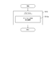
- the defrosting method selects one or more heat transfer tube groups from a plurality of heat transfer tube groups as defrosting target tubes, and defrosts each of the one or more heat transfer tube groups ( Defrost step S10).
- defrosting can be performed by appropriately selecting the defrosting order for each of the one or more heat transfer tube groups, so that the defrosting frequency of the heat transfer tube group where frost easily grows is increased and frosting grows.
- By reducing the defrost frequency of the difficult heat transfer tube group it is possible to suppress a decrease in the operating rate of the heat exchanger due to defrosting.
- the defrosting step S10 when the heat transfer tube group selected as the defrosting target tube is supplied, it is possible to maintain the frost adhesion surface temperature at a temperature lower than 0 ° C. and higher than the temperature of the cooled air.
- the defrost fluid adjusted to the ready state is supplied (defrost fluid condition adjusting step S10a).
- the heat transfer tube group to be defrosted is adjusted to a state in which the temperature of the adhered surface of the frost can be maintained at a temperature lower than 0 ° C. and higher than the temperature of the cooled air when supplied. By supplying a fluid, sublimation defrost becomes possible.
- the cooling medium is supplied from the cooling medium inlet flow path 22 to the heat transfer tubes 16 of all the heat transfer tube groups, and the air to be cooled flowing through the air flow path a is cooled to the set low temperature by the cooling medium. ..
- the defrost operation one of the plurality of heat transfer tube groups is selected, and the defrost fluid is supplied from the defrost passage 32 to the selected heat transfer tube group (defrost step S10).
- the defrost fluid is adjusted by the defrost fluid condition adjusting unit 80 so as to maintain the frost adhesion surface temperature below 0 ° C. and higher than the cooled air when supplied to each heat transfer tube group (the defrost fluid).
- Conditioning step S10a after which it is supplied to the selected heat transfer tube group.
- the frost attached to the heat transfer surface can be sublimated and removed by the heat of the defrost fluid flowing in the heat transfer tube.
- the degree of frost adhesion and growth differs for each heat transfer tube group depending on the position where the heat transfer tubes are arranged, so the time when the gas flow path is blocked by the grown frost layer differs for each heat transfer tube group. Therefore, by appropriately selecting the order of defrosting each heat transfer tube group and the defrosting frequency of each heat transfer tube group, the heat added during defrosting can be prevented while preventing the air passage a on the heat transfer surface of each heat transfer tube group from being blocked. It is possible to suppress a decrease in the thermal efficiency of the heat exchanger 10 due to the above, and to prevent the frost separated from the adhering surface during defrosting from adhering again to the heat transfer surface on the downstream side in the flow direction of the air to be cooled.
- each heat transfer tube group For example, for each heat transfer tube group, the blocking time due to frost formation on the air flow path around the heat transfer surface is obtained, and each heat transfer tube group performs defrost operation at least once per blocking time. Thereby, the blockage of the air flow path of each heat transfer tube group can be suppressed.
- the defrosting operation on the upstream side and the downstream side at the same time, it is possible to suppress the re-adhesion of the frost separated by the upstream heat transfer tube to the downstream heat transfer tube.
- the defrost frequency can be reduced and the decrease in the thermal efficiency of the heat exchanger due to defrost can be suppressed.
- the location of the heat transfer tubes inside the heat exchanger is prevented while preventing the cooled gas from being blocked on the heat transfer surface.
- Heat Exchanger 12 Casing 14 (14a, 14b, 14c) Fan 16 Heat Transfer Tube 20 (20A, 20B, 20C) Refrigerator 22 Cooling Medium Inlet Channel 24 Inlet Branching Channel 26 Cooling Medium Outlet Channel 28 Outlet Branching Channel 30 Cooling Medium valve 32 Defrost flow path 34 (34a, 34b) Defrost branch path 36 Defrost valve 42 Refrigerant circuit 44, 64 Compressor 46, 66 Condenser 48, 68 Expansion valve 50, 74 Receiver 52, 112 Check valve 54 Pressure reducing section 54 (54a) Capillary tube 54 (54b) Pressure reducing valve 55 Solenoid valve 62 Primary circuit 70 Evaporator 72 Secondary circuit 76 Liquid pump 80 (80a, 80b, 80c) Defrost fluid condition control unit 82, 84 Heating unit 86 Buffer tank 88 Refrigerant Supply path 90, 102, 108, 116 Pressure control valve 92, 110 Pressure sensor 94 Control section 96 External heat source heat exchanger 98 Storage tank 100
Landscapes
- Engineering & Computer Science (AREA)
- Physics & Mathematics (AREA)
- Mechanical Engineering (AREA)
- Thermal Sciences (AREA)
- General Engineering & Computer Science (AREA)
- Chemical & Material Sciences (AREA)
- Combustion & Propulsion (AREA)
- Defrosting Systems (AREA)
- Details Of Heat-Exchange And Heat-Transfer (AREA)
Abstract
一実施形態に係る熱交換器は、被冷却気体が流れる気体流路と、同一の前記気体流路内に配置される複数の伝熱管グループと、前記複数の伝熱管グループに冷却媒体を供給するための冷却媒体入口流路と、前記冷却媒体入口流路から分岐して各々の前記伝熱管グループの入口に接続される入口分岐路と、前記複数の伝熱管グループから流出した前記冷却媒体を流すための冷却媒体出口流路と、前記冷却媒体出口流路から分岐して各々の前記伝熱管グループの出口に接続される出口分岐路と、前記複数の伝熱管グループに対してデフロスト流体を供給するためのデフロスト流路と、記デフロスト流路と連通し、各々の前記伝熱管グループの前記入口又は前記出口に接続されるデフロスト分岐路と、前記複数の伝熱管グループの前記デフロスト分岐路に夫々設けられた複数のデフロスト弁と、を備える。
Description
本開示は、熱交換器及び熱交換器のデフロスト方法に関する。
食品などの冷凍に用いる冷凍装置の冷媒として、NH3やCO2等の自然冷媒が見直されている。そこで、冷却性能は高いが毒性があるNH3を一次冷媒とし、無毒及び無臭のCO2を二次冷媒とした冷凍装置が広く用いられている。冷凍庫やフリーザに設けられるエアクーラなどの熱交換器にNH3によって冷却されたCO2が送られ、冷凍庫内の空気を冷却する(特許文献1)。冷凍装置の運転中、エアクーラに設けられた伝熱管に霜が付着し、熱伝達率効率が低下するので、定期的に冷凍装置の運転を中断してデフロストを行う必要がある。
本発明者等は、先にフィンや伝熱管に付着した霜を昇華して除去するデフロスト方法を提案している(特許文献2)。このデフロスト方法は、着霜を昇華させ空気流に乗って飛散させるため、融解水が発生しない。従って、融解水を熱交換器から取り除く作業が不要になると共に、エアクーラの運転を継続しながらデフロストできる利点がある。
本発明者等は、先にフィンや伝熱管に付着した霜を昇華して除去するデフロスト方法を提案している(特許文献2)。このデフロスト方法は、着霜を昇華させ空気流に乗って飛散させるため、融解水が発生しない。従って、融解水を熱交換器から取り除く作業が不要になると共に、エアクーラの運転を継続しながらデフロストできる利点がある。
特許文献1に開示されたデフロスト方法は、冷凍庫内に複数のエアクーラ(熱交換器)を並列に配置しておき、着霜した熱交換器のデフロストを実施し、他方、他の熱交換器の運転を継続するものである。しかし、熱交換器内部の伝熱管の位置によって着霜の程度は異なる。例えば、入口端側にある伝熱管には、熱伝達率が高いために着霜の成長は早まる。これは、空気中で析出したミスト(液体及び固体)が慣性力により入口側に衝突することによる堆積、積層が主な原因である。従って、熱交換器内における伝熱管の位置を考慮せずに、熱交換器毎に一律に順番にデフロストを行っていては、デフロストの実施による熱交換器の稼働率の低下は避けられない。
特許文献2には、熱交換器の伝熱管を複数の領域に分け、一部の領域でデフロストを実施しながら、他の領域で冷却運転を実施することで、冷却運転を継続しながらデフロストを可能にすることが記載されている。しかし、特許文献2には、一部の領域でデフロストを実施しながら、他の領域で冷却運転を実施するアイデアのみが開示されているだけであり、熱交換器内部の伝熱管の位置を考慮したデフロスト方法や、これを行うための流路や配管の構成は開示されていない。
一実施形態は、熱交換器内部の伝熱管の配置場所を考慮したデフロストを行うことで、デフロスト実施による熱交換器の稼働率低下を抑制することを目的とする。
(1)一実施形態に係る熱交換器は、
被冷却気体が流れる気体流路と、
同一の前記気体流路内に配置される複数の伝熱管グループと、
前記複数の伝熱管グループに冷却媒体を供給するための冷却媒体入口流路と、
前記冷却媒体入口流路から分岐して各々の前記伝熱管グループの入口に接続される入口分岐路と、
前記複数の伝熱管グループから流出した前記冷却媒体を流すための冷却媒体出口流路と、
前記冷却媒体出口流路から分岐して各々の前記伝熱管グループの出口に接続される出口分岐路と、
前記複数の伝熱管グループに対してデフロスト流体を供給するためのデフロスト流路と、
前記デフロスト流路と連通し、各々の前記伝熱管グループの前記入口又は前記出口に接続されるデフロスト分岐路と、
前記複数の伝熱管グループの前記デフロスト分岐路にそれぞれ設けられた複数のデフロスト弁と、
を備え、
前記複数のデフロスト弁は、前記複数の伝熱管グループのうちの一部である第1伝熱管グループに対応する前記デフロスト弁を開き、前記複数の伝熱管グループのうち残りの第2伝熱管グループに対応する前記デフロスト弁を閉じることで、前記第2伝熱管グループへの前記冷却媒体の流通状態を維持したまま、前記第1伝熱管グループに対して選択的にデフロストを行うように構成される。
被冷却気体が流れる気体流路と、
同一の前記気体流路内に配置される複数の伝熱管グループと、
前記複数の伝熱管グループに冷却媒体を供給するための冷却媒体入口流路と、
前記冷却媒体入口流路から分岐して各々の前記伝熱管グループの入口に接続される入口分岐路と、
前記複数の伝熱管グループから流出した前記冷却媒体を流すための冷却媒体出口流路と、
前記冷却媒体出口流路から分岐して各々の前記伝熱管グループの出口に接続される出口分岐路と、
前記複数の伝熱管グループに対してデフロスト流体を供給するためのデフロスト流路と、
前記デフロスト流路と連通し、各々の前記伝熱管グループの前記入口又は前記出口に接続されるデフロスト分岐路と、
前記複数の伝熱管グループの前記デフロスト分岐路にそれぞれ設けられた複数のデフロスト弁と、
を備え、
前記複数のデフロスト弁は、前記複数の伝熱管グループのうちの一部である第1伝熱管グループに対応する前記デフロスト弁を開き、前記複数の伝熱管グループのうち残りの第2伝熱管グループに対応する前記デフロスト弁を閉じることで、前記第2伝熱管グループへの前記冷却媒体の流通状態を維持したまま、前記第1伝熱管グループに対して選択的にデフロストを行うように構成される。
上記伝熱管グループは、1つ又は複数の伝熱管で構成される。上記デフロスト弁の開閉操作を行うだけで、簡単にデフロスト流路を複数の伝熱管グループの1つまたは複数に選択的に切り替えることができる。これによって、伝熱管グループ毎に選択的にデフロストを行うことができる。例えば、熱交換器の内部で上流側の伝熱管グループは、他の伝熱管グループより着霜しやすいため、上流側の伝熱管グループのデフロスト頻度を増加できる。従って、着霜の成長の度合いに応じて伝熱管グループ毎にデフロスト頻度を選択できるので、デフロスト実施による熱交換器の稼働率低下を抑制できる。
(2)一実施形態では、前記(1)の構成において、
前記デフロスト分岐路は、各々の前記伝熱管グループの前記出口に接続される。
上記(2)の構成によれば、デフロスト流体は伝熱管グループの出口側から伝熱管グループに供給できる。冷却運転時、伝熱管グループに供給される冷却媒体は液体又は液体と気体の二相流で供給され被冷却気体と熱交換して気体に相変化する。デフロスト時では、デフロスト流体は伝熱管グループに気体で供給され、伝熱管と熱交換して液体に相変化する。そこで、伝熱管を上下方向に配置し、冷却運転時冷却媒体を下方から供給し、冷却媒体は伝熱管との熱交換により蒸発して気体に相変化し、上方から流出するようにする。デフロスト時にデフロスト流体は上方から伝熱管に供給すれば伝熱管との熱交換により凝縮して液体に相変化し流下するようにする。こうして、冷却媒体及びデフロスト流体とも熱交換後の伝熱管からの排出が容易になる。
前記デフロスト分岐路は、各々の前記伝熱管グループの前記出口に接続される。
上記(2)の構成によれば、デフロスト流体は伝熱管グループの出口側から伝熱管グループに供給できる。冷却運転時、伝熱管グループに供給される冷却媒体は液体又は液体と気体の二相流で供給され被冷却気体と熱交換して気体に相変化する。デフロスト時では、デフロスト流体は伝熱管グループに気体で供給され、伝熱管と熱交換して液体に相変化する。そこで、伝熱管を上下方向に配置し、冷却運転時冷却媒体を下方から供給し、冷却媒体は伝熱管との熱交換により蒸発して気体に相変化し、上方から流出するようにする。デフロスト時にデフロスト流体は上方から伝熱管に供給すれば伝熱管との熱交換により凝縮して液体に相変化し流下するようにする。こうして、冷却媒体及びデフロスト流体とも熱交換後の伝熱管からの排出が容易になる。
(3)一実施形態では、前記(1)又は(2)の構成において、
前記デフロスト流路に設けられ前記デフロスト流体の状態を目的の状態に調節可能なデフロスト流体状態調節部を備える。
ここで「デフロスト流体状態調節部」とは、デフロスト流体を加熱や圧力制御弁等によって温度や圧力等を制御して目的の状態にするための調節部であり、目的の状態とは、デフロスト流体をデフロスト対象となった伝熱管グループに供給する際に、霜の付着面温度を0℃未満でかつ被冷却気体の温度以上に維持することができる状態を言う。
上記(3)の構成によれば、上記デフロスト流体状態調節部によって各伝熱管グループに供給された際,霜の付着面温度を0℃未満でかつ被冷却気体の温度より高い温度に維持することができるように調節されたデフロスト流体を、伝熱管グループに供給してデフロストを行うことができる。これによって、融解水が発生しない昇華デフロストが可能になる。従って、融解水を熱交換器から取り除く作業が不要になると共に、他の伝熱管グループで冷却運転を継続しながら、一部の伝熱管グループでデフロストを行うことができる。
前記デフロスト流路に設けられ前記デフロスト流体の状態を目的の状態に調節可能なデフロスト流体状態調節部を備える。
ここで「デフロスト流体状態調節部」とは、デフロスト流体を加熱や圧力制御弁等によって温度や圧力等を制御して目的の状態にするための調節部であり、目的の状態とは、デフロスト流体をデフロスト対象となった伝熱管グループに供給する際に、霜の付着面温度を0℃未満でかつ被冷却気体の温度以上に維持することができる状態を言う。
上記(3)の構成によれば、上記デフロスト流体状態調節部によって各伝熱管グループに供給された際,霜の付着面温度を0℃未満でかつ被冷却気体の温度より高い温度に維持することができるように調節されたデフロスト流体を、伝熱管グループに供給してデフロストを行うことができる。これによって、融解水が発生しない昇華デフロストが可能になる。従って、融解水を熱交換器から取り除く作業が不要になると共に、他の伝熱管グループで冷却運転を継続しながら、一部の伝熱管グループでデフロストを行うことができる。
(4)一実施形態では、前記(3)の構成において、
前記デフロスト流体状態調節部は、前記デフロスト流路に設けられた圧力制御弁を含む。
上記(4)の構成によれば、上記圧力制御弁によってデフロスト流体の圧力制御を行うことで、デフロスト流体の状態を制御し、デフロスト流体を供給した際に霜の付着面温度を0℃未満でかつ被冷却気体の温度より高い温度に維持できるように調節できる。これによって、昇華デフロストが可能になる。
前記デフロスト流体状態調節部は、前記デフロスト流路に設けられた圧力制御弁を含む。
上記(4)の構成によれば、上記圧力制御弁によってデフロスト流体の圧力制御を行うことで、デフロスト流体の状態を制御し、デフロスト流体を供給した際に霜の付着面温度を0℃未満でかつ被冷却気体の温度より高い温度に維持できるように調節できる。これによって、昇華デフロストが可能になる。
(5)一実施形態では、前記(3)の構成において、
前記デフロスト流体状態調節部は、前記デフロスト流路に設けられた加熱部を含む。
上記(5)の構成によれば、上記加熱部によってデフロスト流体の状態を制御し、デフロスト流体を供給した際に霜の付着面温度を0℃未満でかつ被冷却気体の温度より高い温度に調節できる。これによって、昇華デフロストが可能になる。
前記デフロスト流体状態調節部は、前記デフロスト流路に設けられた加熱部を含む。
上記(5)の構成によれば、上記加熱部によってデフロスト流体の状態を制御し、デフロスト流体を供給した際に霜の付着面温度を0℃未満でかつ被冷却気体の温度より高い温度に調節できる。これによって、昇華デフロストが可能になる。
(6)一実施形態では、前記(3)の構成において、
前記デフロスト流体状態調節部は、前記デフロスト流路に設けられ前記デフロスト流体を外部熱源と熱交換させる外部熱源熱交換器を含む。
上記(6)の構成によれば、上記外部熱源熱交換器によってデフロスト流体の状態を制御し、デフロスト流体を供給した際に霜の付着面温度を0℃未満でかつ被冷却気体の温度より高い温度に調節できる。これによって、昇華デフロストが可能になる。
前記デフロスト流体状態調節部は、前記デフロスト流路に設けられ前記デフロスト流体を外部熱源と熱交換させる外部熱源熱交換器を含む。
上記(6)の構成によれば、上記外部熱源熱交換器によってデフロスト流体の状態を制御し、デフロスト流体を供給した際に霜の付着面温度を0℃未満でかつ被冷却気体の温度より高い温度に調節できる。これによって、昇華デフロストが可能になる。
(7)一実施形態では、前記(1)~(6)の何れかの構成において、
前記デフロスト分岐路は各々の前記伝熱管グループの前記入口及び前記出口に設けられ、前記入口に設けられた前記デフロスト分岐路は減圧部を備えると共に、前記冷却媒体入口流路又は前記冷却媒体出口流路に接続される。
上記(7)の構成によれば、デフロストを行う伝熱管グループでデフロストに供された後のデフロスト流体は、上記減圧部で減圧されて低圧の冷却媒体入口流路又は冷却媒体出口流路に戻すことができるので、冷却媒体入口流路又は冷却媒体出口流路の冷却媒体の流れを乱さずにデフロスト流体を冷却媒体流路に戻すことができる。そのため、他の伝熱管グループで冷却運転を安定して継続できる。
前記デフロスト分岐路は各々の前記伝熱管グループの前記入口及び前記出口に設けられ、前記入口に設けられた前記デフロスト分岐路は減圧部を備えると共に、前記冷却媒体入口流路又は前記冷却媒体出口流路に接続される。
上記(7)の構成によれば、デフロストを行う伝熱管グループでデフロストに供された後のデフロスト流体は、上記減圧部で減圧されて低圧の冷却媒体入口流路又は冷却媒体出口流路に戻すことができるので、冷却媒体入口流路又は冷却媒体出口流路の冷却媒体の流れを乱さずにデフロスト流体を冷却媒体流路に戻すことができる。そのため、他の伝熱管グループで冷却運転を安定して継続できる。
(8)一実施形態では、前記(1)~(7)の何れかの構成において、
冷媒が循環する冷媒回路と、
該冷媒回路に設けられた冷凍サイクル構成機器と、
を有する冷凍機を備え、
前記冷却媒体入口流路、前記冷却媒体出口流路及び前記デフロスト流路は、夫々前記冷媒回路に接続されている。
上記(8)の構成によれば、上記冷媒回路を循環する冷媒をデフロスト流体としてデフロスト流路に補給できる。
冷媒が循環する冷媒回路と、
該冷媒回路に設けられた冷凍サイクル構成機器と、
を有する冷凍機を備え、
前記冷却媒体入口流路、前記冷却媒体出口流路及び前記デフロスト流路は、夫々前記冷媒回路に接続されている。
上記(8)の構成によれば、上記冷媒回路を循環する冷媒をデフロスト流体としてデフロスト流路に補給できる。
(9)一実施形態では、前記(8)の構成において、
前記冷凍サイクル構成機器は、前記冷媒を圧縮する圧縮機と、該圧縮機から吐出された前記冷媒を凝縮する凝縮器と、前記凝縮器で凝縮された前記冷媒を貯留するレシーバと、を含み、
前記デフロスト流路は前記レシーバのガス相に接続されている。
上記(9)の構成によれば、デフロスト流路がレシーバのガス相に接続されているので、デフロスト時にレシーバから凝縮器下流側の高温高圧の冷媒ガスを効率良く伝熱管グループに供給できる。
前記冷凍サイクル構成機器は、前記冷媒を圧縮する圧縮機と、該圧縮機から吐出された前記冷媒を凝縮する凝縮器と、前記凝縮器で凝縮された前記冷媒を貯留するレシーバと、を含み、
前記デフロスト流路は前記レシーバのガス相に接続されている。
上記(9)の構成によれば、デフロスト流路がレシーバのガス相に接続されているので、デフロスト時にレシーバから凝縮器下流側の高温高圧の冷媒ガスを効率良く伝熱管グループに供給できる。
(10)一実施形態では、前記(8)の構成において、
前記冷凍サイクル構成機器は、前記冷媒を圧縮する圧縮機と、該圧縮機から吐出された前記冷媒を凝縮する凝縮器と、前記凝縮器で凝縮された前記冷媒を貯留するレシーバと、を含み、
前記デフロスト流路は前記圧縮機の出口側に接続されている。
上記(10)の構成によれば、圧縮機出口側の高温高圧な冷却ガスの保有熱をデフロスト熱源として利用できる。
前記冷凍サイクル構成機器は、前記冷媒を圧縮する圧縮機と、該圧縮機から吐出された前記冷媒を凝縮する凝縮器と、前記凝縮器で凝縮された前記冷媒を貯留するレシーバと、を含み、
前記デフロスト流路は前記圧縮機の出口側に接続されている。
上記(10)の構成によれば、圧縮機出口側の高温高圧な冷却ガスの保有熱をデフロスト熱源として利用できる。
(11)一実施形態では、前記(1)~(7)の何れかの構成において、
冷媒が循環する一次回路と、
該一次回路に設けられた蒸発器を含む冷凍サイクル構成機器と、
被冷却媒体が循環し、前記蒸発器で該被冷却媒体が前記冷媒と熱交換するように構成された二次回路と、
を含んで構成され、
前記冷却媒体入口流路、前記冷却媒体出口流路及び前記デフロスト流路は、前記二次回路に接続されている。
上記(10)の構成によれば、上記二次回路を循環する冷媒をデフロスト流体としてデフロスト流路に補給できる。
冷媒が循環する一次回路と、
該一次回路に設けられた蒸発器を含む冷凍サイクル構成機器と、
被冷却媒体が循環し、前記蒸発器で該被冷却媒体が前記冷媒と熱交換するように構成された二次回路と、
を含んで構成され、
前記冷却媒体入口流路、前記冷却媒体出口流路及び前記デフロスト流路は、前記二次回路に接続されている。
上記(10)の構成によれば、上記二次回路を循環する冷媒をデフロスト流体としてデフロスト流路に補給できる。
(12)一実施形態に係る熱交換器のデフロスト方法は、
被冷却気体が流れる気体流路と、
同一の前記気体流路内に配置される複数の伝熱管グループと、
前記複数の伝熱管グループに冷却媒体を供給するための冷却媒体入口流路と、
前記冷却媒体入口流路から分岐して各々の前記伝熱管グループの入口に接続される入口分岐路と、
前記複数の伝熱管グループから流出した前記冷却媒体を流すための冷却媒体出口流路と、
前記冷却媒体出口流路から分岐して各々の前記伝熱管グループの出口に接続される出口分岐路と、
前記複数の伝熱管グループに対してデフロスト流体を供給するためのデフロスト流路と、
各々の前記伝熱管グループの前記入口又は前記出口に接続されるデフロスト分岐路と、
前記複数の伝熱管グループの前記デフロスト分岐路にそれぞれ設けられた複数のデフロスト弁と、
を備え、
前記複数のデフロスト弁は、前記複数の伝熱管グループのうち一部である第1伝熱管グループに対応する前記デフロスト弁を開き、前記複数の伝熱管グループのうち残りの第2伝熱管グループに対応する前記デフロスト弁を閉じることで、前記第2伝熱管グループへの前記冷却媒体の流通状態を維持したまま、前記第1伝熱管グループに対して選択的にデフロストを行うように構成された熱交換器のデフロスト方法であって、
前記複数の伝熱管グループのうち1以上の前記伝熱管グループをデフロスト対象管として選択し、該1以上の前記伝熱管グループ毎にデフロストするデフロストステップを備える。
被冷却気体が流れる気体流路と、
同一の前記気体流路内に配置される複数の伝熱管グループと、
前記複数の伝熱管グループに冷却媒体を供給するための冷却媒体入口流路と、
前記冷却媒体入口流路から分岐して各々の前記伝熱管グループの入口に接続される入口分岐路と、
前記複数の伝熱管グループから流出した前記冷却媒体を流すための冷却媒体出口流路と、
前記冷却媒体出口流路から分岐して各々の前記伝熱管グループの出口に接続される出口分岐路と、
前記複数の伝熱管グループに対してデフロスト流体を供給するためのデフロスト流路と、
各々の前記伝熱管グループの前記入口又は前記出口に接続されるデフロスト分岐路と、
前記複数の伝熱管グループの前記デフロスト分岐路にそれぞれ設けられた複数のデフロスト弁と、
を備え、
前記複数のデフロスト弁は、前記複数の伝熱管グループのうち一部である第1伝熱管グループに対応する前記デフロスト弁を開き、前記複数の伝熱管グループのうち残りの第2伝熱管グループに対応する前記デフロスト弁を閉じることで、前記第2伝熱管グループへの前記冷却媒体の流通状態を維持したまま、前記第1伝熱管グループに対して選択的にデフロストを行うように構成された熱交換器のデフロスト方法であって、
前記複数の伝熱管グループのうち1以上の前記伝熱管グループをデフロスト対象管として選択し、該1以上の前記伝熱管グループ毎にデフロストするデフロストステップを備える。
上記(12)の方法によれば、上記デフロストステップにおいて、1以上の伝熱管グループ毎にデフロスト順序を適宜選択してデフロストを行うことができる。これによって、着霜が成長しやすい伝熱管グループのデフロスト頻度を増加し、着霜が成長しにくい伝熱管グループのデフロスト頻度を減少させることで、デフロスト実施による熱交換器の稼働率低下を抑制できる。
(13)一実施形態では、前記(12)の方法において、
前記デフロストステップにおいて、
前記デフロスト対象管として選択された前記伝熱管グループに、霜の付着面温度を0℃未満でかつ前記被冷却気体の温度より高い温度に維持することができるように温度調節した前記デフロスト流体を供給する。
上記(12)の方法によれば、デフロスト対象となる伝熱管グループにデフロスト流体を供給した際に、霜の付着面温度を0℃未満でかつ被冷却気体の温度より高い温度に維持することができる状態に調節したデフロスト流体を供給することで、昇華デフロストが可能になる。
前記デフロストステップにおいて、
前記デフロスト対象管として選択された前記伝熱管グループに、霜の付着面温度を0℃未満でかつ前記被冷却気体の温度より高い温度に維持することができるように温度調節した前記デフロスト流体を供給する。
上記(12)の方法によれば、デフロスト対象となる伝熱管グループにデフロスト流体を供給した際に、霜の付着面温度を0℃未満でかつ被冷却気体の温度より高い温度に維持することができる状態に調節したデフロスト流体を供給することで、昇華デフロストが可能になる。
幾つかの実施形態によれば、熱交換器を構成する複数の伝熱管グループの配置場所を考慮し、伝熱管グループ毎にデフロスト頻度を選択できるため、デフロストを効率的に行うことができ、これによって、デフロスト実施による熱交換器の稼働率低下を抑制できる。
以下、添付図面を参照して本発明の幾つかの実施形態について説明する。ただし、実施形態として記載され又は図面に示されている構成部品の寸法、材質、形状、その相対的配置等は、本発明の範囲をこれに限定する趣旨ではなく、単なる説明例にすぎない。
例えば、「ある方向に」、「ある方向に沿って」、「平行」、「直交」、「中心」、「同心」或いは「同軸」等の相対的或いは絶対的な配置を表す表現は、厳密にそのような配置を表すのみならず、公差、若しくは、同じ機能が得られる程度の角度や距離をもって相対的に変位している状態も表すものとする。
例えば、「同一」、「等しい」及び「均質」等の物事が等しい状態であることを表す表現は、厳密に等しい状態を表すのみならず、公差、若しくは、同じ機能が得られる程度の差が存在している状態も表すものとする。
例えば、四角形状や円筒形状等の形状を表す表現は、幾何学的に厳密な意味での四角形状や円筒形状等の形状を表すのみならず、同じ効果が得られる範囲で、凹凸部や面取り部等を含む形状も表すものとする。
一方、一つの構成要素を「備える」、「具える」、「具備する」、「含む」、又は「有する」という表現は、他の構成要素の存在を除外する排他的な表現ではない。
例えば、「ある方向に」、「ある方向に沿って」、「平行」、「直交」、「中心」、「同心」或いは「同軸」等の相対的或いは絶対的な配置を表す表現は、厳密にそのような配置を表すのみならず、公差、若しくは、同じ機能が得られる程度の角度や距離をもって相対的に変位している状態も表すものとする。
例えば、「同一」、「等しい」及び「均質」等の物事が等しい状態であることを表す表現は、厳密に等しい状態を表すのみならず、公差、若しくは、同じ機能が得られる程度の差が存在している状態も表すものとする。
例えば、四角形状や円筒形状等の形状を表す表現は、幾何学的に厳密な意味での四角形状や円筒形状等の形状を表すのみならず、同じ効果が得られる範囲で、凹凸部や面取り部等を含む形状も表すものとする。
一方、一つの構成要素を「備える」、「具える」、「具備する」、「含む」、又は「有する」という表現は、他の構成要素の存在を除外する排他的な表現ではない。
図1は、一実施形態に係る熱交換器を模式的に示す斜視図である。図2~図4は、幾つかの実施形態に係る熱交換器を含む冷凍機の系統図である。図1に示す熱交換器10は、例えば冷凍庫やフリーザなどに設けられ、冷凍庫の庫内空間やフリーザのハウジング内空間を冷却するエアクーラである。熱交換器10のケーシング12の内部は、被冷却空気が流れる流路aが形成される。例えば、図示のように、ケーシング12の前面及び後面は開放されており、ファン14(14a、14b、14c)などの稼働によってケーシング12の前面から流入し後面から流出する被冷却空気の流路aが形成される。この空気流路a中に、複数の伝熱管16が設けられる。伝熱管16は複数の伝熱管グループTa、Tb、Tc、・・・にグループ分けされ、通常の冷却運転時に供給される冷却媒体と、デフロスト運転時に供給されるデフロスト流体は、伝熱管グループ毎に切り替え供給可能に構成されている。上記伝熱管グループは、1つ又は複数の伝熱管16で構成され、複数の伝熱管グループが同一の空気流路aに配置される。
なお、図1において、伝熱管16は、ケーシング12内の上部領域Faのみ図示され、他の中部領域Tb及び下部領域Tcでは伝熱管16の図示は省略されているが、伝熱管16は中部領域Tb及び下部領域Tcにも配置され、上部領域Faの伝熱管グループTa、Tb、Tcと同様に、中部領域Tb及び下部領域Tcにも複数の伝熱管グループが存在している。空気流路aは、矢印c方向に並ぶ複数の流路領域Fa、Fb及びFcを含む。
図2~図4に示す冷凍機20(20A、20B、20C)において、冷却運転時に冷却媒体を伝熱管グループに供給する流路系は、冷却媒体入口流路22と、冷却媒体入口流路22から分岐して各伝熱管グループの入口に接続される入口分岐路24と、で構成される。冷却媒体は冷却媒体入口流路22から各入口分岐路24を介して各伝熱管グループに供給される。
各伝熱管グループから冷却媒体を排出する流路系は、冷却媒体出口流路26と、冷却媒体出口流路から分岐して各伝熱管グループの出口に接続される出口分岐路28と、で構成され、各伝熱管グループで被冷却空気を冷却した冷却媒体は、各伝熱管グループから排出され、各出口分岐路28から冷却媒体出口流路26に排出される。
各伝熱管グループから冷却媒体を排出する流路系は、冷却媒体出口流路26と、冷却媒体出口流路から分岐して各伝熱管グループの出口に接続される出口分岐路28と、で構成され、各伝熱管グループで被冷却空気を冷却した冷却媒体は、各伝熱管グループから排出され、各出口分岐路28から冷却媒体出口流路26に排出される。
デフロスト運転時にデフロスト流体を各伝熱管グループに供給する流路系は、デフロスト流路32と、デフロスト流路32と連通し、各伝熱管グループの入口又は出口に接続されるデフロスト分岐路34(34a、34b)と、で構成され、デフロスト流体は、デフロスト流路32から各デフロスト分岐路34を介して各伝熱管グループに供給される。
なお、各出口分岐路28には冷却媒体弁30が設けられ、各デフロスト分岐路34にはデフロスト弁36が設けられ、これら弁の開閉により伝熱管グループを通る冷却媒体又はデフロスト流体の流路が形成される。
なお、各出口分岐路28には冷却媒体弁30が設けられ、各デフロスト分岐路34にはデフロスト弁36が設けられ、これら弁の開閉により伝熱管グループを通る冷却媒体又はデフロスト流体の流路が形成される。
デフロスト運転では、複数の伝熱管グループTa、Tb、Tc、・・・のうちの一部である伝熱管グループ(例えば、図2及び図4ではTa、図3ではTc)に対応するデフロスト弁36(図3においては加えて対応する電磁弁55)を開き、かつ対応する冷却媒体弁30を閉じ、残りの伝熱管グループに対応するデフロスト弁36(図3においては加えて対応する電磁弁55)を閉じ、かつ対応する冷却媒体弁30を開く。これによって、残りの伝熱管グループへの冷却媒体の流通状態を維持したまま、デフロスト対象とした伝熱管グループに対して選択的にデフロストを行うことができる。
図2~図4に示す冷凍機20(20A~20C)において、デフロスト流体は、冷却運転時に伝熱管16に供給される冷却媒体である。
図2~図4に示す冷凍機20(20A~20C)において、デフロスト流体は、冷却運転時に伝熱管16に供給される冷却媒体である。
上記構成によれば、冷却媒体弁30及びデフロスト弁36(図3においては加えて電磁弁55)の開閉操作を行うだけで、デフロスト流路32及びデフロスト分岐路34で構成されるデフロスト路を簡単に複数の伝熱管グループの1つ又は複数に選択的に切り替えることができる。これによって、伝熱管グループ毎に選択的にデフロストを行うことができる。例えば、熱交換器10の内部で上流側の伝熱管グループは、他の伝熱管グループより着霜しやすいため、上流側の伝熱管グループのデフロスト頻度を増加できる。従って、着霜の成長の度合いに応じて伝熱管グループ毎にデフロスト頻度を選択できるので、デフロスト実施による熱交換器の稼働率低下を抑制できる。
一実施形態では、図1に示すように、熱交換器10において、複数の伝熱管16は、被冷却空気の流れ方向(以下、単に「流れ方向」とも言う。)と直交する方向(幅方向。矢印b方向)に延在し、該流れ方向に互いに間隔を置いて複数列に配置され、かつ該流れ方向及び幅方向と直交する方向(上下方向。矢印c方向)に複数段に配置される。
図1では、ファン14はケーシング12の流れ方向下流側に設けられているが、ケーシング12の流れ方向上流側に設けて押出し型ファンとしてもよい。
図1では、ファン14はケーシング12の流れ方向下流側に設けられているが、ケーシング12の流れ方向上流側に設けて押出し型ファンとしてもよい。
一実施形態では、デフロスト分岐路34は、各伝熱管グループの出口に接続される。これによって、デフロスト流体は伝熱管グループの出口側から伝熱管グループに供給できる。冷却運転時、伝熱管グループに供給される冷却媒体は液体又は液体と気体の二相流で供給され被冷却気体と熱交換して気体に相変化する。デフロスト時では、デフロスト流体は伝熱管グループに気体で供給され、伝熱管16と熱交換して液体に相変化する。そこで、伝熱管16を上下方向に配置し、冷却運転時冷却媒体を下方から供給すれば、冷却媒体は気体に相変化し、上方から流出するようにする。デフロスト時にデフロスト流体は上方から伝熱管に供給すれば液体に相変化し流下するようにする。こうして、冷却媒体及びデフロスト流体とも伝熱管16での熱交換後伝熱管16から容易に排出できる。
一実施形態では、図2に示すように、冷凍機20(20A)は、冷媒が循環する冷媒回路42と、冷媒回路42に設けられた冷凍サイクル構成機器と、を備える。冷却媒体入口流路22、冷却媒体出口流路26及びデフロスト流路32は、夫々冷媒回路42に接続されている。
この実施形態によれば、冷媒回路42を循環する冷媒をデフロスト流体としてデフロスト流路32に補給できる。
一実施形態では、上記冷凍サイクル構成機器は、圧縮機44、凝縮器46及び膨張弁48を含む。冷媒回路42を循環する冷媒は、例えば、NH3、R-404A、CO2であり、冷媒ガスが圧縮機44で圧縮され、凝縮器46で冷却媒体によって冷却されて液化する。液化した冷媒液は膨張弁48を経て減圧された後、冷却媒体入口流路22及び入口分岐路24を経て熱交換器10の伝熱管16に供給され、熱交換器10の伝熱管16で被冷却空気を冷却し気化する。伝熱管16で気化した冷媒ガスは出口分岐路28及び冷却媒体出口流路26を経て冷媒回路42に戻る。
この実施形態によれば、冷媒回路42を循環する冷媒をデフロスト流体としてデフロスト流路32に補給できる。
一実施形態では、上記冷凍サイクル構成機器は、圧縮機44、凝縮器46及び膨張弁48を含む。冷媒回路42を循環する冷媒は、例えば、NH3、R-404A、CO2であり、冷媒ガスが圧縮機44で圧縮され、凝縮器46で冷却媒体によって冷却されて液化する。液化した冷媒液は膨張弁48を経て減圧された後、冷却媒体入口流路22及び入口分岐路24を経て熱交換器10の伝熱管16に供給され、熱交換器10の伝熱管16で被冷却空気を冷却し気化する。伝熱管16で気化した冷媒ガスは出口分岐路28及び冷却媒体出口流路26を経て冷媒回路42に戻る。
一実施形態では、図2に示すように、冷媒回路42に凝縮器46で凝縮された冷媒を貯留するレシーバ50が設けられ、デフロスト流路32はレシーバ50のガス相に接続されている。この実施形態によれば、デフロスト流路32がレシーバ50のガス相に接続されているので、デフロスト時にレシーバ50から凝縮器下流側の高温高圧の冷媒ガスを効率良く熱交換器10の各伝熱管グループに供給できる。
一実施形態では、デフロスト流路32は,圧縮機44の出口側に接続される。例えば、図2に示すように、冷媒回路42から分岐する分岐ライン114が設けられ、分岐ライン114はデフロスト流路32に接続される。分岐ライン114に圧力制御弁116が設けられ、圧力制御弁90及び116の開閉を切り替えることで、デフロスト時に圧縮機44から吐出された高温高圧の冷媒をデフロスト流路32に供給できる。これによって、圧縮機出口側の高温高圧な冷媒の保有熱をデフロスト熱源として利用できる。
一実施形態では、図3及び図4に示す冷凍機20(20B、20C)は、冷媒が循環する一次回路62と、一次回路62に設けられた蒸発器70を含む冷凍サイクル構成機器と、被冷却媒体が循環し、蒸発器70で該被冷却媒体が冷媒と熱交換するように構成された二次回路72と、を含んで構成されている。冷却媒体入口流路22、冷却媒体出口流路26及びデフロスト流路32は、二次回路72に接続されている。
この実施形態によれば、二次回路72を循環する冷媒をデフロスト流体としてデフロスト流路32に補給できる。
一実施形態では、一次回路62には他の冷凍サイクル構成機器として、圧縮機64、凝縮器66、膨張弁68が設けられる。一次回路62を循環する冷媒はNH3であり、二次回路72を循環する被冷却媒体はCO2であり、被冷却媒体は液ポンプ76によって二次回路72を循環する。
この実施形態によれば、二次回路72を循環する冷媒をデフロスト流体としてデフロスト流路32に補給できる。
一実施形態では、一次回路62には他の冷凍サイクル構成機器として、圧縮機64、凝縮器66、膨張弁68が設けられる。一次回路62を循環する冷媒はNH3であり、二次回路72を循環する被冷却媒体はCO2であり、被冷却媒体は液ポンプ76によって二次回路72を循環する。
一実施形態では、二次回路72に蒸発器70で一次回路62を循環する冷媒と熱交換して液化された被冷却媒体を貯留するレシーバ74を備える。レシーバ74を備えるため、二次回路72を流れる被冷却媒体の循環量の自由度が広がり、伝熱管16に供給する被冷却媒体又はデフロスト流体の流量調節が容易になる。
図3に示す実施形態では、デフロスト流路32は冷却媒体入口流路22及び冷却媒体出口流路26を介してレシーバ74に接続されている。この実施形態では、デフロスト流路32はレシーバ74を経由しない閉ループを形成できるので、デフロスト流体の循環量を節減できる。
図4に示す実施形態では、デフロスト流路32の上流側端は蓄圧タンク98に直接接続され、下流側端は伝熱管グループの下流側で冷却媒体入口流路22に接続されている。従って、デフロストによってデフロスト流体が得た冷熱をデフロスト対象ではない伝熱管グループで有効に利用できる。
図4に示す実施形態では、デフロスト流路32の上流側端は蓄圧タンク98に直接接続され、下流側端は伝熱管グループの下流側で冷却媒体入口流路22に接続されている。従って、デフロストによってデフロスト流体が得た冷熱をデフロスト対象ではない伝熱管グループで有効に利用できる。
一実施形態では、図2~図4に示すように、デフロスト流路32にデフロスト流体の状態を調節可能なデフロスト流体状態調節部80(80a、80b、80c)を備える。デフロスト流体状態調節部80によって各伝熱管グループに供給されるデフロスト流体を、各伝熱管グループに供給した際に霜の付着面温度を0℃未満でかつ被冷却気体の温度より高い温度に維持することができる状態に調節した後、各伝熱管グループに供給してデフロストを行うことができる。これによって、融解水が発生しない昇華デフロストが可能になる。従って、融解水を熱交換器から取り除く作業が不要になると共に、冷却媒体弁30及びデフロスト弁36(図3においては加えて電磁弁55)の開閉操作によって他の伝熱管グループで冷却運転を継続しながら、一部の伝熱管グループでデフロストを行うことができる。
一実施形態では、図2及び図3に示すように、デフロスト流体状態調節部80(80a、80b)は、デフロスト流路32に設けられた加熱部82及び84を含む。加熱部82及び84によってデフロスト流体の状態を制御し、デフロスト流体を、各伝熱管グループに供給した際に霜の付着面温度を0℃未満でかつ被冷却気体の温度より高い温度に維持することができるように調節できる。これによって、昇華デフロストが可能になる。
一実施形態では、図2に示すように、バッファタンク86がデフロスト流路32に設けられ、加熱部82はバッファタンク86に設けられる。デフロスト流路32から各伝熱管グループに供給されるデフロスト流体は、バッファタンク86に一時貯留され、バッファタンク86に設けられた加熱部82によって昇華デフロストが可能な状態に調節される。
一実施形態では、図2に示すように、バッファタンク86がデフロスト流路32に設けられ、加熱部82はバッファタンク86に設けられる。デフロスト流路32から各伝熱管グループに供給されるデフロスト流体は、バッファタンク86に一時貯留され、バッファタンク86に設けられた加熱部82によって昇華デフロストが可能な状態に調節される。
一実施形態では、図2に示すように、圧縮機44から吐出される高温高圧の冷媒ガスが冷媒供給路88を通って加熱部82に供給される。冷媒供給路88を介して供給される高温高圧の冷媒ガスによってデフロスト流体は加熱され、昇華デフロストが可能な状態に調節される。
一実施形態では、図3に示す冷凍機20(20B)において、冷却媒体弁30とデフロスト弁36および電磁弁55の開閉によってデフロスト対象となった伝熱管グループを含むデフロスト流路32は閉回路を形成し、加熱部84は加熱用熱交換器で構成される。デフロスト流路32においてデフロスト流体はサーモサイフォン作用によって自然循環する。
一実施形態では、図3に示す冷凍機20(20B)において、冷却媒体弁30とデフロスト弁36および電磁弁55の開閉によってデフロスト対象となった伝熱管グループを含むデフロスト流路32は閉回路を形成し、加熱部84は加熱用熱交換器で構成される。デフロスト流路32においてデフロスト流体はサーモサイフォン作用によって自然循環する。
一実施形態では、図2、図3及び図4に示すように、デフロスト流体状態調節部80(80a、80b、80c)は、デフロスト流路32に設けられた圧力制御弁90及び102を含む。圧力制御弁90又は102によってデフロスト流体の圧力制御を行うことで、デフロスト流体の状態を制御し、デフロスト流体を、各伝熱管グループに供給した際に霜の付着面温度を0℃未満でかつ被冷却気体の温度より高い温度に維持することができるように調節できる。これによって、昇華デフロストが可能になる。
一実施形態では、図2に示すように、デフロスト流路32の圧力制御弁90の下流側に圧力センサ92が設けられる。制御部94は、各伝熱管グループの伝熱管16に供給されるデフロスト流体の状態が昇華デフロストが可能な状態になるように、圧力センサ92の検出値に応じて圧力制御弁90の開度を制御する。これによって、伝熱管16に供給されるデフロスト流体の状態を昇華デフロストが可能な状態に精度良く制御できる。
一実施形態では、図2に示すように、デフロスト流路32の圧力制御弁90の下流側に圧力センサ92が設けられる。制御部94は、各伝熱管グループの伝熱管16に供給されるデフロスト流体の状態が昇華デフロストが可能な状態になるように、圧力センサ92の検出値に応じて圧力制御弁90の開度を制御する。これによって、伝熱管16に供給されるデフロスト流体の状態を昇華デフロストが可能な状態に精度良く制御できる。
一実施形態では、図4に示すように、デフロスト流体状態調節部80(80c)は、デフロスト流路32に設けられた外部熱源熱交換器96を含む。外部熱源熱交換器96でデフロスト流体は外部熱源と熱交換される。外部熱源熱交換器96によってデフロスト流体の状態を制御し、デフロスト流体を、各伝熱管グループに供給した際に霜の付着面温度を0℃未満でかつ被冷却気体の温度より高い温度に維持することができるように調節できる。これによって、昇華デフロストが可能になる。この実施形態では、デフロスト流体の状態調節に外部熱源を用いることができるため、熱源の選択の自由度が高い。
外部熱源熱交換器96の熱源は、例えば外気であってもよく、あるいは他の熱源でもよい。例えば、凝縮器66で冷媒を冷却した冷却媒体の保有熱を熱源としてもよい。
外部熱源熱交換器96の熱源は、例えば外気であってもよく、あるいは他の熱源でもよい。例えば、凝縮器66で冷媒を冷却した冷却媒体の保有熱を熱源としてもよい。
霜の付着面温度を調節する際に、冷却媒体の凝縮を利用して付着面を加熱する場合、目的とする温度から求められる凝縮圧力を主として制御の基準パラメータとする。この理由は、デフロスト流体の温度で制御する場合、冷却媒体の過熱(飽和状態から外れる状態)などの変動要素が加わることと、温度分布があるためどこの温度を計測して制御するか等の問題があるため、温度を基準パラメータとしにくいからである。
一実施形態では、図2及び図4に示すように、デフロスト分岐路34(34a、34b)は各伝熱管グループの入口及び出口に設けられ、入口に設けられたデフロスト分岐路34(34b)は減圧部54を備えると共に、冷却媒体入口流路22又は冷却媒体出口流路26に接続される。
この実施形態によれば、デフロストを行う伝熱管グループでデフロストに供された後のデフロスト流体は、減圧部54(54a、54b)で減圧されて低圧の冷却媒体入口流路22又は冷却媒体出口流路26に戻すことができるので、冷却媒体入口流路22又は冷却媒体出口流路26の冷却媒体の流れを乱さずに、デフロスト流体をこれら冷却媒体流路に戻すことができる。そのため、他の伝熱管グループで冷却運転を安定して継続できる。
図2に示す実施形態では、入口側デフロスト分岐路34(34b)は、冷却媒体入口流路22に接続されている。
一実施形態では、入口分岐路24に冷却媒体が各伝熱管グループから冷却媒体入口流路22に逆流するのを防止する逆止弁52が設けられている。
この実施形態によれば、デフロストを行う伝熱管グループでデフロストに供された後のデフロスト流体は、減圧部54(54a、54b)で減圧されて低圧の冷却媒体入口流路22又は冷却媒体出口流路26に戻すことができるので、冷却媒体入口流路22又は冷却媒体出口流路26の冷却媒体の流れを乱さずに、デフロスト流体をこれら冷却媒体流路に戻すことができる。そのため、他の伝熱管グループで冷却運転を安定して継続できる。
図2に示す実施形態では、入口側デフロスト分岐路34(34b)は、冷却媒体入口流路22に接続されている。
一実施形態では、入口分岐路24に冷却媒体が各伝熱管グループから冷却媒体入口流路22に逆流するのを防止する逆止弁52が設けられている。
図2及び図4に示す実施形態では、減圧部54(54a、54b)は入口側デフロスト分岐路34(34b)に設けられ、入口側デフロスト分岐路34(34b)は冷却媒体入口流路22に接続されている。減圧部54は、図2に示すようにキャピラリチューブ54(54a)であってもよいし、図4に示すように減圧弁54(54b)であってもよい。なお、図3に示す実施形態では、デフロスト流体はデフロスト流路32をサーモサイフォン作用によって自然循環するため、入口側デフロスト分岐路34(34b)に減圧弁54(54b)でなく電磁弁55が設けられる。
一実施形態では、図3及び図4に示すように、加熱部84又は外部熱源熱交換器96の下流側のデフロスト流路32に蓄圧タンク98が設けられている。これにより、デフロスト流体が各伝熱管グループに供給された際に温度及び圧力が急激に低下することを緩和できる。
一実施形態では、図2~図4に示すように、デフロスト流路32とレシーバ74とを接続する圧力調整路100が設けられる。デフロスト流路32が異常高圧となったとき、圧力調整路100に設けられた圧力制御弁102によって、一部のデフロスト流体を、図2に示す実施形態では低圧側冷媒回路42に逃し、図3及び図4に示す実施形態ではレシーバ74に逃すことで圧力調整が可能になる。
一実施形態では、図2~図4に示すように、デフロスト流路32とレシーバ74とを接続する圧力調整路100が設けられる。デフロスト流路32が異常高圧となったとき、圧力調整路100に設けられた圧力制御弁102によって、一部のデフロスト流体を、図2に示す実施形態では低圧側冷媒回路42に逃し、図3及び図4に示す実施形態ではレシーバ74に逃すことで圧力調整が可能になる。
一実施形態では、図4に示すように、デフロスト流路32に高圧ポンプ104が設けられ、レシーバ74内の被冷却媒体ガスは高圧ポンプ104によってデフロスト流体としてデフロスト流路32に供給される。レシーバ74と高圧ポンプ104下流側のデフロスト流路32とに接続される圧力調整路106が設けられ、圧力調整路106に圧力制御弁108、圧力センサ110が設けられ、デフロスト流路32に逆止弁112が設けられている。圧力センサ110の検出値に基づき圧力制御弁108の開度を制御することで、高圧ポンプ104下流側のデフロスト流体の圧力を制御する。
一実施形態に係るデフロスト方法は、図5に示すように、複数の伝熱管グループのうち1以上の伝熱管グループをデフロスト対象管として選択し、該1以上の前記伝熱管グループ毎にデフロストする(デフロストステップS10)。
上記方法によれば、1以上の伝熱管グループ毎にデフロスト順序を適宜選択してデフロストを行うことができるため、着霜が成長しやすい伝熱管グループのデフロスト頻度を増加し、着霜が成長しにくい伝熱管グループのデフロスト頻度を減少させることで、デフロスト実施による熱交換器の稼働率低下を抑制できる。
上記方法によれば、1以上の伝熱管グループ毎にデフロスト順序を適宜選択してデフロストを行うことができるため、着霜が成長しやすい伝熱管グループのデフロスト頻度を増加し、着霜が成長しにくい伝熱管グループのデフロスト頻度を減少させることで、デフロスト実施による熱交換器の稼働率低下を抑制できる。
一実施形態では、デフロストステップS10において、デフロスト対象管として選択された伝熱管グループに、供給した際に霜の付着面温度を0℃未満でかつ被冷却空気の温度より高い温度に維持することができる状態に調節したデフロスト流体を供給する(デフロスト流体状態調節ステップS10a)。この実施形態によれば、デフロスト対象となる伝熱管グループに、供給した際に霜の付着面温度を0℃未満でかつ被冷却空気の温度より高い温度に維持することができる状態に調節したデフロスト流体を供給することで、昇華デフロストが可能になる。
通常の冷却運転では、すべての伝熱管グループの伝熱管16に冷却媒体入口流路22から冷却媒体が供給され、冷却媒体によって空気流路aを流れる被冷却空気が設定された低温に冷却される。デフロスト運転時には、複数の伝熱管グループのひとつを選択し、選択された伝熱管グループにデフロスト流路32からデフロスト流体を供給する(デフロストステップS10)。デフロスト流体はデフロスト流体状態調節部80で、各伝熱管グループに供給した際に霜の付着面温度を0℃未満でかつ被冷却空気より高い温度に維持することができるように調節され(デフロスト流体状態調節ステップS10a)、その後、選択された伝熱管グループに供給される。デフロスト流体が供給された伝熱管グループでは、伝熱管内を流れるデフロスト流体の熱により伝熱面に付着した霜を昇華させ除去することができる。これを別な伝熱管グループに順々に行っていくことで、熱交換器10の稼働中に全伝熱管のデフロストが可能になると共に、各伝熱管グループでデフロストを行う順序を適宜選択することでデフロストを効率良く行うことができる。
伝熱管が配置される位置によって、伝熱管グループ毎に霜の付着及び成長の度合いは異なるため、成長した霜層によって気体流路が閉塞される時間は、伝熱管グループ毎に異なる。そこで、各伝熱管グループをデフロストする順序や各伝熱管グループのデフロスト頻度を適宜選択することで、各伝熱管グループの伝熱面における空気流路aの閉塞を防止しながら、デフロスト時加えられる熱による熱交換器10の熱効率の低下を抑制し、かつデフロスト時に付着面から剥離した霜が被冷却空気の流れ方向下流側の伝熱面に再付着するのを抑制できる。
例えば、伝熱管グループ毎に伝熱面周囲の空気流路の着霜による閉塞時間を求めておき、各伝熱管グループで閉塞時間当たり少なくとも1回のデフロスト運転を行うようにする。これによって、各伝熱管グループの空気流路の閉塞を抑制できる。あるいは、同一流路領域においては、上流側と下流側とで同時にデフロスト運転を行うことで、上流側伝熱管で剥離した霜が下流側伝熱管に再付着するのを抑制できる。あるいは、着霜の成長が遅い下流側伝熱管グループほどデフロストの時間間隔を長くすることで、デフロスト頻度を低減し、デフロストによる熱交換器の熱効率の低下を抑制できる。
幾つかの実施形態によれば、冷凍庫やフリーザ等に設けられたエアクーラなどの熱交換器において、伝熱面における被冷却気体の閉塞を防止しながら、熱交換器内部の伝熱管の配置場所を考慮した効率的なデフロストを行うことで、デフロスト実施による熱交換器の稼働率低下を抑制できる。
10 熱交換器
12 ケーシング
14(14a、14b、14c) ファン
16 伝熱管
20(20A、20B、20C) 冷凍機
22 冷却媒体入口流路
24 入口分岐路
26 冷却媒体出口流路
28 出口分岐路
30 冷却媒体弁
32 デフロスト流路
34(34a、34b) デフロスト分岐路
36 デフロスト弁
42 冷媒回路
44、64 圧縮機
46、66 凝縮器
48、68 膨張弁
50、74 レシーバ
52、112 逆止弁
54 減圧部
54(54a) キャピラリチューブ
54(54b) 減圧弁
55 電磁弁
62 一次回路
70 蒸発器
72 二次回路
76 液ポンプ
80(80a、80b、80c) デフロスト流体状態調節部
82、84 加熱部
86 バッファタンク
88 冷媒供給路
90、102、108,116 圧力制御弁
92、110 圧力センサ
94 制御部
96 外部熱源熱交換器
98 蓄圧タンク
100、106 圧力調整路
104 高圧ポンプ
114 分岐ライン
Fa、Fb、Fc 流路領域
Fa 上部領域
Fb 中部領域
Fc 下部領域
Ta、Tb、Tc 伝熱管グループ
a 空気流路
12 ケーシング
14(14a、14b、14c) ファン
16 伝熱管
20(20A、20B、20C) 冷凍機
22 冷却媒体入口流路
24 入口分岐路
26 冷却媒体出口流路
28 出口分岐路
30 冷却媒体弁
32 デフロスト流路
34(34a、34b) デフロスト分岐路
36 デフロスト弁
42 冷媒回路
44、64 圧縮機
46、66 凝縮器
48、68 膨張弁
50、74 レシーバ
52、112 逆止弁
54 減圧部
54(54a) キャピラリチューブ
54(54b) 減圧弁
55 電磁弁
62 一次回路
70 蒸発器
72 二次回路
76 液ポンプ
80(80a、80b、80c) デフロスト流体状態調節部
82、84 加熱部
86 バッファタンク
88 冷媒供給路
90、102、108,116 圧力制御弁
92、110 圧力センサ
94 制御部
96 外部熱源熱交換器
98 蓄圧タンク
100、106 圧力調整路
104 高圧ポンプ
114 分岐ライン
Fa、Fb、Fc 流路領域
Fa 上部領域
Fb 中部領域
Fc 下部領域
Ta、Tb、Tc 伝熱管グループ
a 空気流路
Claims (13)
- 被冷却気体が流れる気体流路と、
同一の前記気体流路内に配置される複数の伝熱管グループと、
前記複数の伝熱管グループに冷却媒体を供給するための冷却媒体入口流路と、
前記冷却媒体入口流路から分岐して各々の前記伝熱管グループの入口に接続される入口分岐路と、
前記複数の伝熱管グループから流出した前記冷却媒体を流すための冷却媒体出口流路と、
前記冷却媒体出口流路から分岐して各々の前記伝熱管グループの出口に接続される出口分岐路と、
前記複数の伝熱管グループに対してデフロスト流体を供給するためのデフロスト流路と、
前記デフロスト流路と連通し、各々の前記伝熱管グループの前記入口又は前記出口に接続されるデフロスト分岐路と、
前記複数の伝熱管グループの前記デフロスト分岐路にそれぞれ設けられた複数のデフロスト弁と、
を備え、
前記複数のデフロスト弁は、前記複数の伝熱管グループのうち一部である第1伝熱管グループに対応する前記デフロスト弁を開き、前記複数の伝熱管グループのうち残りの第2伝熱管グループに対応する前記デフロスト弁を閉じることで、前記第2伝熱管グループへの前記冷却媒体の流通状態を維持したまま、前記第1伝熱管グループに対して選択的にデフロストを行うように構成されたことを特徴とする熱交換器。 - 前記デフロスト分岐路は、各々の前記伝熱管グループの前記出口に接続されることを特徴とする請求項1に記載の熱交換器。
- 前記デフロスト流路に設けられ前記デフロスト流体の状態を調節可能なデフロスト流体状態調節部を備えることを特徴とする請求項1又は2に記載の熱交換器。
- 前記デフロスト流体状態調節部は、前記デフロスト流路に設けられた圧力制御弁を含むことを特徴とする請求項3に記載の熱交換器。
- 前記デフロスト流体状態調節部は、前記デフロスト流路に設けられた加熱部を含むことを特徴とする請求項3に記載の熱交換器。
- 前記デフロスト流体状態調節部は、前記デフロスト流路に設けられ前記デフロスト流体を外部熱源と熱交換させる外部熱源熱交換器を含むことを特徴とする請求項3に記載の熱交換器。
- 前記デフロスト分岐路は、各々の前記伝熱管グループの前記入口及び前記出口に設けられ、
前記入口に設けられた前記デフロスト分岐路は減圧部を備えると共に、前記冷却媒体入口流路又は前記冷却媒体出口流路に接続されることを特徴とする請求項1乃至6の何れか一項に記載の熱交換器。 - 冷媒が循環する冷媒回路と、
該冷媒回路に設けられた冷凍サイクル構成機器と、
を有する冷凍機を備え、
前記冷却媒体入口流路、前記冷却媒体出口流路及び前記デフロスト流路は、夫々前記冷媒回路に接続されていることを特徴とする請求項1乃至7の何れか一項に記載の熱交換器。 - 前記冷凍サイクル構成機器は、前記冷媒を圧縮する圧縮機と、該圧縮機から吐出された前記冷媒を凝縮する凝縮器と、前記凝縮器で凝縮された前記冷媒を貯留するレシーバと、を含み、
前記デフロスト流路は前記レシーバのガス相に接続されていることを特徴とする請求項8に記載の熱交換器。 - 前記冷凍サイクル構成機器は、前記冷媒を圧縮する圧縮機と、該圧縮機から吐出された前記冷媒を凝縮する凝縮器と、前記凝縮器で凝縮された前記冷媒を貯留するレシーバと、を含み、
前記デフロスト流路は前記圧縮機の出口側に接続されていることを特徴とする請求項8に記載の熱交換器。 - 冷媒が循環する一次回路と、
該一次回路に設けられた蒸発器を含む冷凍サイクル構成機器と、
被冷却媒体が循環し、前記蒸発器で該被冷却媒体が前記冷媒と熱交換するように構成された二次回路と、
を含んで構成され、
前記冷却媒体入口流路、前記冷却媒体出口流路及び前記デフロスト流路は、前記二次回路に接続されていることを特徴とする請求項1乃至7の何れか一項に記載の熱交換器。 - 被冷却気体が流れる気体流路と、
同一の前記気体流路内に配置される複数の伝熱管グループと、
前記複数の伝熱管グループに冷却媒体を供給するための冷却媒体入口流路と、
前記冷却媒体入口流路から分岐して各々の前記伝熱管グループの入口に接続される入口分岐路と、
前記複数の伝熱管グループから流出した前記冷却媒体を流すための冷却媒体出口流路と、
前記冷却媒体出口流路から分岐して各々の前記伝熱管グループの出口に接続される出口分岐路と、
前記複数の伝熱管グループに対してデフロスト流体を供給するためのデフロスト流路と、
各々の前記伝熱管グループの前記入口又は前記出口に接続されるデフロスト分岐路と、
前記複数の伝熱管グループの前記デフロスト分岐路にそれぞれ設けられた複数のデフロスト弁と、
を備え、
前記複数のデフロスト弁は、前記複数の伝熱管グループのうち一部である第1伝熱管グループに対応する前記デフロスト弁を開き、前記複数の伝熱管グループのうち残りの第2伝熱管グループに対応する前記デフロスト弁を閉じることで、前記第2伝熱管グループへの前記冷却媒体の流通状態を維持したまま、前記第1伝熱管グループに対して選択的にデフロストを行うように構成された熱交換器のデフロスト方法であって、
前記複数の伝熱管グループのうち1以上の前記伝熱管グループをデフロスト対象管として選択し、該1以上の前記伝熱管グループ毎にデフロストするデフロストステップを備えることを特徴とする熱交換器のデフロスト方法。 - 前記デフロストステップにおいて、
前記デフロスト対象管として選択された前記伝熱管グループに、霜の付着面温度を0℃未満でかつ前記被冷却気体の温度より高い温度に維持することができるように状態を調節した前記デフロスト流体を供給することを特徴とする請求項12に記載の熱交換器のデフロスト方法。
Applications Claiming Priority (2)
| Application Number | Priority Date | Filing Date | Title |
|---|---|---|---|
| JP2018-213228 | 2018-11-13 | ||
| JP2018213228A JP7208769B2 (ja) | 2018-11-13 | 2018-11-13 | 熱交換器及び熱交換器のデフロスト方法 |
Publications (1)
| Publication Number | Publication Date |
|---|---|
| WO2020100767A1 true WO2020100767A1 (ja) | 2020-05-22 |
Family
ID=70730269
Family Applications (1)
| Application Number | Title | Priority Date | Filing Date |
|---|---|---|---|
| PCT/JP2019/043986 Ceased WO2020100767A1 (ja) | 2018-11-13 | 2019-11-08 | 熱交換器及び熱交換器のデフロスト方法 |
Country Status (2)
| Country | Link |
|---|---|
| JP (1) | JP7208769B2 (ja) |
| WO (1) | WO2020100767A1 (ja) |
Cited By (1)
| Publication number | Priority date | Publication date | Assignee | Title |
|---|---|---|---|---|
| DE102022205256A1 (de) | 2022-05-25 | 2023-11-30 | Robert Bosch Gesellschaft mit beschränkter Haftung | Wärmepumpeneinrichtung |
Citations (5)
| Publication number | Priority date | Publication date | Assignee | Title |
|---|---|---|---|---|
| JPS50145056U (ja) * | 1974-05-17 | 1975-12-01 | ||
| JPS5727371B2 (ja) * | 1976-07-30 | 1982-06-10 | ||
| JPH01107055A (ja) * | 1987-10-21 | 1989-04-24 | Hitachi Ltd | 調温調湿設備の除霜制御方法、及び同装置 |
| WO2015093235A1 (ja) * | 2013-12-17 | 2015-06-25 | 株式会社前川製作所 | 冷凍装置の昇華デフロストシステム及び昇華デフロスト方法 |
| WO2017175411A1 (ja) * | 2016-04-07 | 2017-10-12 | 株式会社前川製作所 | 昇華による除霜方法、昇華による除霜装置及び冷却装置 |
-
2018
- 2018-11-13 JP JP2018213228A patent/JP7208769B2/ja active Active
-
2019
- 2019-11-08 WO PCT/JP2019/043986 patent/WO2020100767A1/ja not_active Ceased
Patent Citations (5)
| Publication number | Priority date | Publication date | Assignee | Title |
|---|---|---|---|---|
| JPS50145056U (ja) * | 1974-05-17 | 1975-12-01 | ||
| JPS5727371B2 (ja) * | 1976-07-30 | 1982-06-10 | ||
| JPH01107055A (ja) * | 1987-10-21 | 1989-04-24 | Hitachi Ltd | 調温調湿設備の除霜制御方法、及び同装置 |
| WO2015093235A1 (ja) * | 2013-12-17 | 2015-06-25 | 株式会社前川製作所 | 冷凍装置の昇華デフロストシステム及び昇華デフロスト方法 |
| WO2017175411A1 (ja) * | 2016-04-07 | 2017-10-12 | 株式会社前川製作所 | 昇華による除霜方法、昇華による除霜装置及び冷却装置 |
Cited By (1)
| Publication number | Priority date | Publication date | Assignee | Title |
|---|---|---|---|---|
| DE102022205256A1 (de) | 2022-05-25 | 2023-11-30 | Robert Bosch Gesellschaft mit beschränkter Haftung | Wärmepumpeneinrichtung |
Also Published As
| Publication number | Publication date |
|---|---|
| JP2020079678A (ja) | 2020-05-28 |
| JP7208769B2 (ja) | 2023-01-19 |
Similar Documents
| Publication | Publication Date | Title |
|---|---|---|
| US7104079B2 (en) | Heat pump | |
| KR101790462B1 (ko) | 냉동 장치의 디프로스트 시스템 및 냉각 유닛 | |
| JP5595140B2 (ja) | ヒートポンプ式給湯・空調装置 | |
| US7028494B2 (en) | Defrosting methodology for heat pump water heating system | |
| US20180266743A1 (en) | Air-conditioning apparatus | |
| US11635233B2 (en) | Cooling system | |
| KR20170013766A (ko) | 냉장고 | |
| US8011192B2 (en) | Method for defrosting an evaporator in a refrigeration circuit | |
| JP2011179697A (ja) | 冷凍サイクル装置および冷温水装置 | |
| AU2012391144B2 (en) | Refrigerator and method of controlling refrigerator | |
| JP7105933B2 (ja) | 冷凍装置の室外機およびそれを備える冷凍装置 | |
| TWI676773B (zh) | 冷凍裝置及溫度控制裝置 | |
| JP2013137123A (ja) | 冷凍装置 | |
| JP5677472B2 (ja) | 冷凍装置 | |
| JP7208769B2 (ja) | 熱交換器及び熱交換器のデフロスト方法 | |
| US10443913B2 (en) | Refrigerator and method for controlling the same | |
| JP6338565B2 (ja) | 冷凍装置 | |
| US20200132348A1 (en) | Cooling system | |
| JP5256622B2 (ja) | 冷凍装置 | |
| JP2016125785A (ja) | 冷凍装置 | |
| KR102785541B1 (ko) | 유니트쿨러 냉동시스템의 냉매순환장치 및 방법 | |
| JP7647043B2 (ja) | 冷却装置 | |
| US20240377116A1 (en) | Refrigerator | |
| JP2000274911A (ja) | 冷却システム | |
| JP6412702B2 (ja) | 冷凍装置及び冷凍装置の運転方法 |
Legal Events
| Date | Code | Title | Description |
|---|---|---|---|
| 121 | Ep: the epo has been informed by wipo that ep was designated in this application |
Ref document number: 19885989 Country of ref document: EP Kind code of ref document: A1 |
|
| NENP | Non-entry into the national phase |
Ref country code: DE |
|
| 122 | Ep: pct application non-entry in european phase |
Ref document number: 19885989 Country of ref document: EP Kind code of ref document: A1 |