WO2020100747A1 - 動物のストレス軽減用器材 - Google Patents
動物のストレス軽減用器材 Download PDFInfo
- Publication number
- WO2020100747A1 WO2020100747A1 PCT/JP2019/043922 JP2019043922W WO2020100747A1 WO 2020100747 A1 WO2020100747 A1 WO 2020100747A1 JP 2019043922 W JP2019043922 W JP 2019043922W WO 2020100747 A1 WO2020100747 A1 WO 2020100747A1
- Authority
- WO
- WIPO (PCT)
- Prior art keywords
- animal
- protrusion
- reducing device
- stress
- stress reducing
- Prior art date
- Legal status (The legal status is an assumption and is not a legal conclusion. Google has not performed a legal analysis and makes no representation as to the accuracy of the status listed.)
- Ceased
Links
Images




Classifications
-
- A—HUMAN NECESSITIES
- A01—AGRICULTURE; FORESTRY; ANIMAL HUSBANDRY; HUNTING; TRAPPING; FISHING
- A01K—ANIMAL HUSBANDRY; AVICULTURE; APICULTURE; PISCICULTURE; FISHING; REARING OR BREEDING ANIMALS, NOT OTHERWISE PROVIDED FOR; NEW BREEDS OF ANIMALS
- A01K15/00—Devices for taming animals, e.g. nose-rings or hobbles; Devices for overturning animals in general; Training or exercising equipment; Covering boxes
-
- A—HUMAN NECESSITIES
- A01—AGRICULTURE; FORESTRY; ANIMAL HUSBANDRY; HUNTING; TRAPPING; FISHING
- A01K—ANIMAL HUSBANDRY; AVICULTURE; APICULTURE; PISCICULTURE; FISHING; REARING OR BREEDING ANIMALS, NOT OTHERWISE PROVIDED FOR; NEW BREEDS OF ANIMALS
- A01K29/00—Other apparatus for animal husbandry
-
- A—HUMAN NECESSITIES
- A61—MEDICAL OR VETERINARY SCIENCE; HYGIENE
- A61D—VETERINARY INSTRUMENTS, IMPLEMENTS, TOOLS, OR METHODS
- A61D99/00—Subject matter not provided for in other groups of this subclass
-
- A—HUMAN NECESSITIES
- A61—MEDICAL OR VETERINARY SCIENCE; HYGIENE
- A61H—PHYSICAL THERAPY APPARATUS, e.g. DEVICES FOR LOCATING OR STIMULATING REFLEX POINTS IN THE BODY; ARTIFICIAL RESPIRATION; MASSAGE; BATHING DEVICES FOR SPECIAL THERAPEUTIC OR HYGIENIC PURPOSES OR SPECIFIC PARTS OF THE BODY
- A61H39/00—Devices for locating or stimulating specific reflex points of the body for physical therapy, e.g. acupuncture
- A61H39/04—Devices for pressing such points, e.g. Shiatsu or Acupressure
-
- A—HUMAN NECESSITIES
- A61—MEDICAL OR VETERINARY SCIENCE; HYGIENE
- A61H—PHYSICAL THERAPY APPARATUS, e.g. DEVICES FOR LOCATING OR STIMULATING REFLEX POINTS IN THE BODY; ARTIFICIAL RESPIRATION; MASSAGE; BATHING DEVICES FOR SPECIAL THERAPEUTIC OR HYGIENIC PURPOSES OR SPECIFIC PARTS OF THE BODY
- A61H39/00—Devices for locating or stimulating specific reflex points of the body for physical therapy, e.g. acupuncture
- A61H39/08—Devices for applying needles to such points, i.e. for acupuncture ; Acupuncture needles or accessories therefor
Definitions
- the present invention relates to equipment for reducing stress in animals.
- Animals related to humans such as companion animals and industrial animals are often exposed to stress such as transport stress, heat stress, sleep disorders, reproductive disorders and lactation disorders. For example, when animals are transported, many animals exhibit excessive stress reactions such as motion sickness like humans. It is known that dogs, which are companion animals, exhibit symptoms similar to motion sickness such as vomiting and loss of energy when transported by a car or the like.
- pigs which are industrial animals, in addition to the problem of physical condition such as diarrhea due to transport stress, the meat quality is reduced (meat meat and dandruff meat), which causes price reduction, or internal waste disposal due to pancreatic infiltration is caused, which is economical.
- Develop into loss A calf becomes ill with diarrhea or fever, and a horse develops transport fever.
- Patent Document 1 discloses a method for reducing transport stress of an animal, which comprises applying a physical stimulus to a predetermined site on the body surface of the animal such as a meridian before starting the transport of the animal.
- circular skin acupuncture is used to give physical stimulation to the animals.
- the circular acupuncture needle is attached to the animal's body surface with adhesive tape.
- the circular skin acupuncture needle may be accidentally ingested by an animal when it is peeled off from the body surface, and there is room for improvement in safety.
- the present invention has been made in view of the above circumstances, and an object of the present invention is to provide a device for stress reduction of animals that can reduce stress more safely.
- a support that is held with the first surface facing the body surface of the animal;
- a protrusion projecting from the first surface toward the body surface of the animal, and stimulating a meridian of the animal, Equipped with
- the support is Having a second surface facing the protrusion, Sandwiching the auricle of the animal between the protrusion and the second surface,
- the support and the protrusion Made of biodegradable material.
- the protrusion is There are three, It may be that.
- the support is A first support member having the first surface; A second support member having the second surface; A connecting portion that connects one end of the first support member and one end of the second support member; With It may be that.
- the protruding portion protruding from the second surface is There are three, It may be that.
- a perpendicular to the first surface that passes through the tip of the protruding portion protruding from the first surface is Passing through the tip of the protrusion protruding from the second surface, It may be that.
- the protrusion is A needle that pierces the body surface of the animal, It may be that.
- the protrusion is It is a rod shape that presses the body of the animal, It may be that.
- the protrusion is It is a cone shape that presses the body of the animal, It may be that.
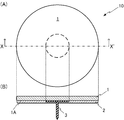
- FIG. 1 It is a figure which shows the stress-relief device which concerns on Embodiment 1 of this invention.
- A shows a plan view of a stress reducing device.
- B shows a sectional view of the stress reducing device. It is a figure which illustrates the position of the ear point of the animal which has an auricle.
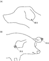
- A is a figure which shows the position of the ear point of a dog.
- B is a figure which shows the position of the auricle of a pig.
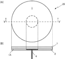
- A) shows a plan view of a stress reducing device.
- B shows a sectional view of the stress reducing device.
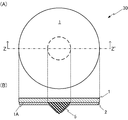
- FIG. 1 shows a plan view of a stress reducing device.
- B shows a sectional view of the stress reducing device. It is a figure which shows the stress reduction equipment which concerns on Embodiment 2 of this invention.
- A) shows a plan view of a stress reducing device.
- B) shows a front view of the stress reducing device. It is a figure which shows the stress reduction equipment which concerns on Embodiment 3 of this invention.
- A) shows a plan view of a stress reducing device.
- (B) shows a front view of the stress reducing device.
- FIG. 3 It is a figure which shows the modification of the stress reduction equipment which concerns on Embodiment 3 of this invention.
- A shows a plan view of a stress reducing device.
- B shows a front view of the stress reducing device. It is a figure which shows the stress-reducing equipment which concerns on Embodiment 4 of this invention.
- A shows a plan view of a stress reducing device.
- B shows a front view of the stress reducing device.
- A) shows a plan view of a stress reducing device.
- B shows a front view of the stress reducing device. It is a figure which shows the modification of the stress reduction equipment which concerns on Embodiment 5 of this invention.
- (A) shows a plan view of a stress reducing device.
- (B) shows a front view of the stress reducing device. It is a figure which shows the stress reduction equipment which concerns on Embodiment 6 of this invention.
- (A) shows a front view of a stress reducing device.
- (B) shows a plan view of the stress reducing device.
- (C) shows a side view of the stress reducing device. It is a figure which shows the modification of the stress reduction equipment which concerns on Embodiment 6 of this invention.
- (A) shows a front view of a stress reducing device.
- (B) shows a plan view of the stress reducing device.
- (C) shows a side view of the stress reducing device.
- the stress reducing device 10 is used to prevent, reduce or eliminate stress on animals.
- the animals to which the stress reducing device 10 is applied are preferably mammals, and particularly preferably mammals excluding humans. Examples of animals include companion animals (pets and care animals), livestock, racehorses, experimental animals, and exhibited animals.
- the animals are pigs, dogs, cows, cats, monkeys, rabbits, squirrels, mice, rats, guinea pigs, hamsters, horses, sheep and goats.
- the stress-reducing device 10 includes a support 1, a sticking member 2, and a protrusion 3.
- FIG. 1A shows a plan view of the stress reducing device 10.
- the support 1 is circular in plan view.
- FIG. 1B shows the stress reducing device 10 when the stress reducing device 10 is cut along the one-dot broken line X-X ′ in FIG.
- the support 1 has a surface 1A (first surface).
- the surface of the surface 1A is covered with the attachment member 2.
- the sticking member 2 is not particularly limited as long as it is a sticky member that sticks to the body surface of the animal. Before being attached to an animal, the attaching member 2 is protected by a release paper whose surface is subjected to a release process.
- the support 1 is held on the body surface of the animal via the attachment member 2. That is, the support 1 is held with the surface 1A facing the body surface of the animal.
- the size of the support 1 is appropriately set depending on the size of the animal used, the strength of adhesion of the sticking member 2 to the body surface, and the like. Returning to FIG. 1A, the size of the support 1 is such that the circular diameter in plan view is, for example, 10 to 50 mm, 10 to 40 mm, or 20 to 30 mm.
- the protrusion 3 is provided on the surface 1A and protrudes from the surface 1A.
- the stress reducing device 10 is held on the body surface of an animal at a position where the tip of the protrusion 3 stimulates a meridian (pot).
- the protrusion 3 is a needle that pierces the body surface of an animal. Thereby, when the support 1 is held on the body surface of the animal, the protrusion 3 stimulates the meridian of the animal.
- the meridian is particularly preferably the auricle located on the blood vessels of the auricle along the back surface of the left and right auricles.
- the auricles are one point at the positions shown in FIG. 2A for each of the left and right auricles, and for the pigs, there are three points at the positions of the left and right auricles at the positions shown in FIG.
- the length of the protruding portion 3 (the length from the surface 1A to the tip of the protruding portion 3) is appropriately set according to the size of the animal or the part of the animal to be held, but is, for example, 0.5 to 5 mm, 0. It is 8 to 4 mm, 1 to 3 mm or 1.2 to 2 mm.
- the protrusion 3 has a length of 1.5 mm.
- the thickness of the protrusion 3 is appropriately set depending on the size of the animal or the part of the animal to be held, but is 0.1 to 0.5 mm or 0.2 to 0.4 mm.
- the support 1, the attachment member 2 and the protrusion 3 are made of a biodegradable material.
- the biodegradable material is, for example, a naturally degradable material.
- Biodegradable materials include acrylonitrile butadiene styrene (ABS), polylactic acid (PLA), PHA (polyhydroxyalkanoic acid), starch, modified starch, polycaprolactone, polyhydroxyalkanoate, polyglycolic acid, modified polyvinyl alcohol. , Cellulose acetate, casein, and the like.
- the biodegradable material is starch.
- starch is adopted as the biodegradable material
- the support 1 is made of starch paper such as wafer
- the sticking member 2 is made of starch paste
- the protrusions 3 are made of solid starch.
- the stress reducing device 10 is peeled from the release paper and attached to the surface of the animal's body.
- the part of the animal to which the stress reducing device 10 is attached is not particularly limited as long as the protrusion 3 stimulates the meridian.
- the protrusion 3 is inserted into the body surface above the ear tip.
- the stress to be reduced is any stress that causes some physical changes.
- the stress is transport stress, heat stress, sleep disorders, reproductive disorders, lactation disorders and the like.
- the intensity of stress can be evaluated using, for example, an index of physiological response to acute stress.
- an index of physiological reaction an indicator which has little individual difference, is hardly affected by other physiological reactions, and responds rapidly according to the intensity of stress is preferably used.
- physiological reaction indicators preferably used for evaluation of stress intensity include blood cortisol concentration, blood adrenaline concentration, blood noradrenaline concentration and blood dopamine concentration.
- the stress-reducing device 10 when reducing transport stress, it is preferable to use the stress-reducing device 10 on an animal at a predetermined time before the start of transport.
- start using the stress-reducing device 10 before the start of transportation depends on the type of animal, the type of transportation means, the internal environment of the transportation means, etc. It is preferable to start the use about 60 minutes before. In the case of small to medium sized pigs, it is preferable to use them immediately before the start of transportation, for example, about 30 to 60 minutes.
- the stress reducing device 10 may be used continuously during transportation. Examples of the transportation means include an automobile, a railroad, a ship, and an aircraft, but the transportation means is not particularly limited, and the stress-reducing device 10 can be used in any transportation means normally used for transporting animals. ..
- the support 1, the attaching member 2 and the protrusion 3 are made of a biodegradable material. Therefore, even if the animal accidentally eats or swallows the stress reducing device 10, it is quickly decomposed in the body of the animal, so that the safety is high.
- the protrusion 3 protrudes from the surface 1A toward the body surface of the animal, and can stimulate the meridian of the animal. As shown in the Examples below, by stimulating the meridian, the effect of reducing the stress in the brain of the animal associated with transportation and the effect of preventing the exacerbation of blood oxidative stress can be obtained.
- the stress reducing device 10 may be used so that the protrusion 3 stimulates the ear tip.
- the auricle is a region where the mouth and forelimbs are hard to reach, and therefore the risk of the animal removing the stress reducing device 10 by itself, or accidentally eating or swallowing is low. Is preferred.
- the protrusion 3 is a needle that pierces the surface of the animal's body, but the shape of the protrusion 3 is not limited to a needle and is not particularly limited as long as it can stimulate the meridian.
- FIG. 3A shows a plan view of a stress reducing device 20 which is a modified example of the stress reducing device 10.
- FIG. 3B shows the stress-reducing device 20 when the stress-reducing device 20 is cut along the one-dot broken line Y-Y ′ in FIG.
- the stress-reducing device 20 includes, in place of the protrusion 3 in the stress-reducing device 10, a rod-shaped protrusion 4 that presses the animal body.
- the length and thickness of the protrusion 4 are similar to those of the protrusion 3.
- the protrusion 4 is also made of a biodegradable material.
- FIG. 4A shows a plan view of a stress reducing device 30 which is a modified example of the stress reducing device 10.
- FIG. 4B shows the stress reducing device 30 when the stress reducing device 30 is cut along the one-dot broken line ZZ ′ in FIG.
- the stress reducing device 30 includes, in place of the protrusion 3 of the stress reducing device 10, a protrusion 5 having a cone shape that presses the body of the animal.
- the protrusion 5 is made of a biodegradable material.
- the protrusion 5 has a cone-shaped apex facing the body surface of the animal and presses the body to stimulate the meridian of the animal.
- the protrusion 5 has a conical shape, but may have a conical shape such as a triangular pyramid and a quadrangular pyramid.
- the height of the protrusion 5 (the length from the surface 1A to the apex of the protrusion 5) is, for example, 0.5 to 5 mm, 0.8 to 4 mm, 1 to 3 mm, or 1.2 to 2 mm.
- the diameter of the bottom surface of the protrusion 5 in plan view is not particularly limited as long as it is shorter than the diameter of the support 1, and is, for example, 1 to 10 mm, 2 to 8 mm, or 4 to 6 mm.
- the apex angle of the protrusion 5 (the apex angle of an isosceles triangle when the protrusion 5 having a conical shape is cut along a plane passing through the rotation axis of the cone) is, for example, 45 to 135 °.
- the protrusion 4 of the stress reducing device 20 has a rod shape.
- the protrusion 5 of the stress reducing device 30 has a cone shape. Therefore, when the support 1 is attached to the body surface of the animal, it is possible to prevent an accident such as the user accidentally sticking the needle to the animal or injuring a moving animal with the needle.
- FIG. 5A shows a plan view of the stress reducing device 40.
- the stress reducing device 40 includes, in place of the support 1, a support 6 having a triangular shape in a plan view.
- the support 6 is preferably an equilateral triangle, and the length of one side thereof is 40 to 100 mm, 50 to 80 mm or 60 to 70 mm.
- FIG. 5 (B) shows the stress reducing device 40 when viewed from the horizontal direction.
- the stress reducing device 40 includes three protrusions 7 a, 7 b and 7 c instead of the protrusion 5.
- Each of the protrusions 7a, 7b and 7c is similar to the protrusion 5.
- the protrusions 7a, 7b, and 7c are arranged such that the center of the bottom surface of each of the protrusions 7a, 7b, and 7c is the apex of an equilateral triangle in plan view.
- the length of one side of the equilateral triangle that is, the distance L1 between the center of the bottom surface of the protrusion 7a and the center of the bottom surface of the protrusion 7b is, for example, 10 to 15 mm, 11 to 14 mm, or 12 to 13 mm.
- the stress-reducing device 40 is used to reduce stress in pigs, cows and the like.
- Each of the protrusions 7a, 7b and 7c can reduce stress on the animal by pressing the ear tips.
- the distance L1 is appropriately adjusted according to the distance between the ear tips.
- the support 6 is an equilateral triangle, it may be circular or quadrangular in plan view like the support 1.
- the number of the protrusions 7a and the like is not limited to three and may be plural, for example, two, four, five, six, and 7 to 10.
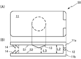
- FIG. 6A shows a plan view of the stress reducing device 50.
- the stress reducing device 50 includes a support 11, a connecting portion 12, a protruding portion 13, and a fastening portion 14.
- FIG. 6B shows the stress reducing device 50 when viewed from the horizontal direction.
- the support 11 includes a support member 11a and a support member 11b.
- the support body 11, the connecting portion 12, the protruding portion 13, and the fastening portion 14 are all made of a biodegradable material.
- the support members 11a and 11b are made of a biodegradable material having elasticity.
- the one end of the support member 11a and the one end of the support member 11b are connected via the connecting portion 12.
- the support member 11a has a surface S1 (first surface).
- the surface S1 is provided with a conical projection 13 that projects from the surface S1 toward the support member 11b.
- the surface S1 faces the body surface of the animal.
- the support member 11b has a surface S2 (second surface) that faces the surface S1. That is, the surface S2 faces the protrusion 13.
- the height, the diameter of the bottom surface, and the angle of the apex of the protrusion 13 are the same as those of the protrusion 5 of the stress reducing device 30.
- the fastening portions 14 are provided at the other end of the surface S1 connected to the support member 11b and the other end of the surface S2 connected to the support member 11a.
- the fastening portion 14 is one or more protrusions provided on each of the surfaces S1 and S2.
- the retainer 14 holds the support member 11a and the support member 11b on the body surface so that the protrusion 13 does not deviate from the position where the protrusion 13 stimulates the meridian.
- the distance L2 between the surface S1 and the surface S2 and the distance L3 between the tip of the protrusion 13 and the surface S2 are set according to the thickness of the part of the animal inserted between the support member 11a and the support member 11b.
- L2 is 1.5 to 10 mm, 2 to 9 mm, 3 to 8 mm or 4 to 6 mm
- L3 is 0.5. -6 mm, 1-5 mm, 1.5-4 mm, 2-3.5 mm or 2.5-3 mm.
- the support member 11a Since the support member 11a has elasticity, the support member 11 can be moved from the closed state shown in FIG. 6B to the open state in which the support member 11a is pulled up so that the surface S1 is separated from the surface S2 in the vertical direction. .
- the auricle of the animal After applying force to the support member 11a to open it, the auricle of the animal is inserted between the support member 11a and the support member 11b, and the force applied to the support member 11a is unloaded to return to the closed state.
- the support 11 can sandwich the pinna of the animal between the protrusion 13 and the surface S2, and the stress reducing device 50 is held on the body surface of the animal.
- the protrusion 13 presses the ear tip to apply stimulation to the ear tip.
- the stress reducing device 50 since the pinna of the animal can be sandwiched between the protrusion 13 and the support member 11b, the meridian of the animal can be more reliably stimulated. it can. In the stress reducing device 50, since the protrusion 13 is between the support member 11a and the supporting member 11b, the protrusion 13 is not exposed to the outside even if the stress reducing device 50 comes off the body surface of the animal. High safety.
- the stress reducing device 50 has one protrusion 13 but may have a plurality of protrusions 13.
- the number of protrusions 13 is preferably three.
- the stress reducing device 50 may include a mechanism for urging the support member 11a toward the support member 11b so that the surface S1 approaches the surface S2. ..
- the mechanism is realized by a known means.
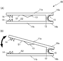
- the stress reducing device 50 includes an elastic member 15 formed of a biodegradable material.
- the support member 11a and the support member 11b have an extending portion 16a and an extending portion 16b, respectively, in which the end opposite to the end where the retaining portion 14 is provided extends from the connecting portion 12 in the direction opposite to the retaining portion 14.
- the elastic member 15 is interposed between the extending portion 16a and the extending portion 16b.
- the support member 11a is rotatable with respect to the support member 11b about the connecting portion 12 as an axis.
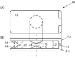
- FIG. 8A shows a plan view of the stress reducing device 60.
- the stress reducing device 60 further has a protrusion 17 on the surface S2 of the support member 11b.
- the projecting portion 17 projects from the surface S2 toward the surface S1.
- the protruding portion 17 protrudes toward the body surface of the animal.
- the protrusion 17 is formed of a biodegradable material, and the height, the diameter of the bottom surface, and the angle of the apex of the protrusion 17 are the same as those of the protrusion 5 of the stress reducing device 30.
- FIG. 8 (B) shows the stress reducing device 60 when viewed from the horizontal direction.
- a perpendicular line to the surface S1 passing through the tip of the protrusion 13 protruding from the surface S1 passes through the tip of the protrusion 17 protruding from the surface S2. Therefore, for example, pressure can be applied to the auricle from both sides of the auricle. By doing so, as compared with the case where the perpendicular to the surface S1 passing through the tip of the protrusion 13 does not pass through the tip of the protrusion 17, the pressing of the protrusion 13 and the protrusion 17 on the meridian can be strengthened.
- the distance L2 between the surfaces S1 and S2 and the distance L4 between the tip of the protrusion 13 and the tip of the protrusion 17 depend on the thickness of the part of the animal inserted between the support member 11a and the support member 11b. Is set. Table 1 shows the thicknesses of the left and right auricles and L2 and L4 exemplified by considering the thickness, for each animal species having the auricle.
- the perpendicular to the surface S1 passing through the tip of the protrusion 13 passes through the tip of the protrusion 17, so that the protrusion 13 and the protrusion 17 increase the pressing force on the meridian as described above. You can Thereby, the stress of the animal can be reduced more efficiently.
- the perpendicular to the surface S1 passing through the tip of the protrusion 13 may not pass through the tip of the protrusion 17. In this case, even if the position of the stress-relieving device 60 attached to the animal on the body surface is displaced so that the tip of the protrusion 13 presses the ear tip, the tip of the protrusion 17 presses the ear tip. Can reduce the stress of.
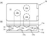
- FIG. 9A shows a plan view of the stress reducing device 70.
- the support member 11a has three protrusions 13a, 13b and 13c on the surface S1.
- the support member 11b has three protrusions 17a, 17b and 17c on the surface S2.
- FIG. 9 (B) shows the stress reducing device 70 when viewed from the horizontal direction.
- the perpendicular to the surface S1 passing through the tip of the protrusion 13a does not pass through the tip of the protrusion 17a facing the protrusion 13a.
- the arrangement of the protrusions 13a, 13b and 13c in plan view is the same as the arrangement of the protrusions 7a, 7b and 7c in the stress reducing device 40 according to the second embodiment.
- the arrangement of the protrusions 17a, 17b and 17c in plan view is also the same as the arrangement of the protrusions 7a, 7b and 7c.
- the stress-reducing device 70 is suitable for pigs, cows, etc., which have three ear tips. Even if the position of the stress reducing device 70 attached to the animal is shifted on the body surface so that the tips of the protrusions 13a, 13b, and 13c press the ear tips, the tips of the protrusions 17a, 17b, and 17c press the ear tips. By doing so, the stress of the animal can be reduced.
- FIG. 10A shows a plan view of a stress reducing device 80 which is a modified example of the stress reducing device 70.
- FIG. 10 (B) shows the stress reducing device 80 when viewed from the horizontal direction.
- the supporting member 11a has six protrusions 13a to 13f on the surface S1.
- the support member 11b has six protrusions 17a to 17f on the surface S2.
- the stress reducing device 80 since the support member 11a and the support member 11b each have six protrusions 13a to 13f and protrusions 17a to 17f, it is possible to apply pressure to many meridians. Thereby, the stress of the animal can be reduced more efficiently. Further, for example, even if the position of the stress reducing device 80 attached to the animal such that the tip of the protrusion 13b presses the meridian is displaced on the body surface, the protrusions 13a and 13c to 13f, and the protrusion 17a to The stress on the animal can be reduced by pressing the meridian with any one of the ends 17f.
- FIG. 11A shows the stress reducing device 90 when viewed from the front in the horizontal direction.
- the stress reducing device 90 includes a support body 91 integrally formed of a biodegradable material having elasticity.
- the support 91 has a surface S1 and a surface S2, and the auricle is inserted between the surface S1 and the surface S2.
- the surface S1 of the inserted auricle which is held facing the body surface of the auricle, is provided with three protrusions 13a, 13b, and 13c protruding from the surface S1 toward the body surface of the auricle. ..
- Fastening portions 14 are provided on the surfaces S1 and S2, respectively.
- the support 91 has a surface S2 'that is raised from the bottom and is closer to the projection 13a than the surface S2 at a position facing the tips of the projections 13a, 13b, and 13c.
- the distance between the tips of the protrusions 13a, 13b and 13c and the surface S2 ' is set according to the thickness of the auricle of the animal used.
- the distance between the tip of the protrusions 13a, 13b and 13c and the surface S2 ′ is 0.5 to 6 mm, 1 to 5 mm, 1.5 to 4 mm, 2 to 3.5 mm or 2.5 to 3 mm, preferably It is 2 mm.
- the height of the protrusions 13a, 13b and 13c is, for example, 1 to 5 mm, 1.2 to 4 mm or 11.5 to 3.5 mm or 2 to 3 mm, preferably 2.5 mm.
- FIG. 11 (B) shows a plan view of the stress reducing device 90.
- the protrusions 13a, 13b, and 13c are arranged such that the centers of the bottom surfaces of the protrusions 13a, 13b, and 13c are the vertices of an equilateral triangle in plan view.
- the diameter of the bottom surface of each of the protrusions 13a, 13b, and 13c in plan view is 4 to 6 mm, preferably 3 mm.
- the length of one side of the equilateral triangle, that is, the distance between the center of the bottom surface of the protrusion 13a and the center of the bottom surface of the protrusion 13b is, for example, 9 to 13 mm or 10 to 12 mm, preferably 11 mm.
- the length L5 and the width L6 of the support 91 are set according to the size of the animal using the stress reducing device 90 or the part of the animal holding the stress reducing device 90.
- L5 is 40 to 60 mm or 45 to 55 mm, preferably 50 mm.
- L6 is 10 to 30 mm or 15 to 22 mm, preferably 16 or 18 mm.
- FIG. 11C shows the stress reducing device 90 when viewed horizontally from the side.
- the height L7 of the support 91 is, for example, 10 to 15 mm, 11 to 14 mm, or 12 to 13 mm.
- the height L8 of the surface S2 or less of the support 91 is, for example, 1 to 5 mm, 2 to 4 mm, and preferably 3 mm.
- the auricle of the animal is placed between the surface S1 and the surface S2 in a state where the side of the support body 91 where the surface S1 is present is pulled up so that the surface S1 is separated from the surface S2 in the vertical direction.
- the pinna of the animal can be sandwiched between the protrusions 13a, 13b and 13c and the surface S2 ′, and the stress reducing device 90 is held on the body surface of the animal. If the stress reducing device 90 is attached at a position where the protrusions 13a, 13b, and 13c press the ear tips, the protrusions 13a, 13b, and 13c press the ear tips to apply stimulation to the ear tips.
- the stress reducing device 90 since the support 91 is integrally formed of a biodegradable material, the stress reducing device 90 can be manufactured more simply and inexpensively.
- the stress reducing device 90 may have the auricle sandwiched between the protrusions 13a, 13b and 13c and the retaining portion 14 provided on the surface S2.
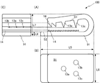
- FIG. 12 (A) shows a stress reducing device 100 when the stress reducing device 100, which is a modified example of the stress reducing device 90, is viewed from the front.
- the stress reducing device 100 will be described mainly with respect to differences from the stress reducing device 90.
- the retaining portion 14 provided on the surface S2 is arranged at a position facing the respective tips of the protrusions 13a, 13b, and 13c.
- the height of the fastening portion 14 provided on the surface S1 (the height from the surface S1 to the tip of the fastening portion 14) is, for example, 1 to 4 mm, 1.5 to 3 mm, preferably 2 mm, and the height is provided on the surface S2.
- the height of the fastening portion 14 thus formed (the height from the surface S2 to the tip of the fastening portion 14) is, for example, 0.5 to 3 mm or 0.8 to 2 mm, preferably 1 mm.
- the height of the protrusions 13a, 13b and 13c is, for example, 1 to 5 mm, 1.2 to 4 mm or 11.5 to 3.5 mm, preferably 2 to 3 mm.
- the height of the protrusion 13a may be different from the height of the protrusions 13b and 13c.
- the height of the protrusions 13b and 13c may be 3 mm.
- the distances between the tips of the protrusions 13a, 13b and 13c and the tips of the retaining portions 14 provided on the surface S2 are 0.5 to 6 mm, 1 to 5 mm, 1.5 to 4 mm, 2 to 3.5 mm and 2. It is 5 to 3 mm, preferably 1.5 mm or 2 mm.
- FIG. 12 (B) shows a plan view of the stress reducing device 100.
- the protrusions 13a, 13b, and 13c are arranged such that the centers of the bottom surfaces of the protrusions 13a, 13b, and 13c are the vertices of an equilateral triangle in plan view.
- the diameter of the bottom surface of the protrusions 13a, 13b and 13c in plan view is 4 to 6 mm, preferably 3 mm.
- the diameter of the bottom surface of the protrusion 13a may be different from the diameter of the bottom surface of the protrusions 13b and 13c. For example, when the diameter of the bottom surface of the protrusion 13a is 3 mm, the diameter of the bottom surface of the protrusions 13b and 13c is 3.5 mm.
- the length L5 and the width L6 of the support 91 are set depending on the size of the animal to be used and the part to be held.
- L5 is 30 to 60 mm or 32 to 50 mm, preferably 33 to 35 mm.
- L6 is 10 to 30 mm or 15 to 22 mm, preferably 16 or 18 mm.
- FIG. 12 (C) shows the stress reducing device 100 when viewed horizontally from the side.
- the height L7 of the support 91 is, for example, 10 to 15 mm, 11 to 14 mm, or 12 to 13 mm.
- the height L8 of the support 91 below the surface S2 is, for example, 1 to 5 mm, 2 to 4 mm, and preferably 1.5 to 2.5 mm.
- the auricle of the animal By inserting the auricle of the animal between the surface S1 and the surface S2 in a state where the surface S1 of the support 91 is pulled up so that the surface S1 is separated from the surface S2 in the vertical direction, The pinna of the animal can be sandwiched between the protrusions 13a, 13b and 13c and the retaining portion 14 provided on the surface S2, and the stress reducing device 100 is held on the body surface of the animal. Since the retaining portion 14 is caught on the body surface of the animal, the support 91 is more firmly held on the body surface of the animal.
- the protrusions 13a, 13b, and 13c press the ear tips to more reliably apply stimulation to the ear tips.
- stress reducing devices 50, 60, 70, 80, 90 and 100 in which each member is not formed of a biodegradable material are provided.
- the protrusion 13 is between the support member 11a and the support member 11b, the protrusion 13 is not exposed to the outside and safety can be secured.
- the number of the protrusions 13a and the like in the stress reducing devices 90 and 100 may be one, two, or four or more. Further, one or more protrusions 13a and the like may be provided on the surface S2 of the stress reducing devices 90 and 100. Further, in the present embodiment, the centers of the bottom surfaces of the protrusions 13a, 13b, and 13c are arranged to be the vertices of an equilateral triangle in plan view, but the present invention is not limited to this, and the The arrangement may be changed according to the positional relationship of the meridians.
- 9 pigs (micro mini pig, adult, male, Fuji Micra) were divided into control group, test group A and test group B (3 animals in each group). All heads were shipped from Yamanashi Prefecture to Kagoshima Prefecture in 8.5 hours. In detail, first, all of them were shipped from Tokyo to Yamanashi by land over 5.5 hours. Then, all of them were transported by air to Kagoshima prefecture over 2 hours, and further by land for 1 hour. The day of transportation was fasted, and drinking water was freely available. Immediately before transportation (about 30 to 60 minutes before), the pigs in the test group A were each provided with three circular skin acupuncture needles (manufactured by Seirin Co., Ltd.) attached to the ear tips. To the pigs in test group B, three round skin acupuncture needles were attached to the ear tips 48 hours before transportation. No cuticle acupuncture was applied to the pigs in the control group.
- blood stress markers cortisol, adrenaline, noradrenaline and free fatty acids
- blood oxidative stress indexes were measured.
- a free fatty acid c-test manufactured by Wako Pure Chemical Industries, Ltd.
- a free radical analyzer freecario Duo, manufactured by Wismer
- kit d-ROMs test for measuring the degree of oxidation and antioxidative power are measured.
- BAP test all manufactured by Wismer Co. was used.
- FIG. 13 shows the increase rates of stress markers in blood before and after the transportation. Cortisol was elevated by transport in all groups and was not different between groups, indicating that all pigs were stressed by approximately 8.5 hours of transport by air and air. The test group A tended to suppress the rate of increase in adrenaline and noradrenaline as compared with the control group.
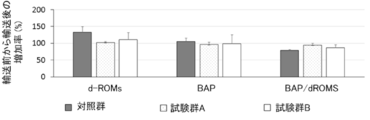
- Fig. 14 shows the increase rate of blood oxidative stress index before and after transportation.
- test group A an increase in d-ROMs, which is an index of oxidative stress, was suppressed.
- test group A the rate of increase in the ratio of BAP, which is an index of antioxidative activity against d-ROMs, was higher than that in the control group. Therefore, it was shown that oxidative stress in blood is suppressed by applying stimulation to the ear tip just before transportation.
- the present invention is suitable for maintaining the health of animals, particularly for treating or preventing deterioration of physical condition due to stress.
Landscapes
- Life Sciences & Earth Sciences (AREA)
- Health & Medical Sciences (AREA)
- Animal Behavior & Ethology (AREA)
- Rehabilitation Therapy (AREA)
- Veterinary Medicine (AREA)
- Environmental Sciences (AREA)
- Public Health (AREA)
- General Health & Medical Sciences (AREA)
- Zoology (AREA)
- Animal Husbandry (AREA)
- Biodiversity & Conservation Biology (AREA)
- Epidemiology (AREA)
- Pain & Pain Management (AREA)
- Physical Education & Sports Medicine (AREA)
- Wood Science & Technology (AREA)
- Engineering & Computer Science (AREA)
- Finger-Pressure Massage (AREA)
Abstract
本発明は、より安全にストレスを軽減することができる動物のストレス軽減用器材を提供することを目的とする。 動物のストレス軽減用器材(50)は、動物の体表面に面(S1)を対向させて保持される支持体(11)と、面(S1)から動物の体表面に向かって突起しており、動物の経絡を刺激する突起部(13)と、を備える。支持体(11)は、突起部(13)に対向する面(S2)を有し、突起部(13)と面(S2)との間に動物の耳介を挟む。支持体(11)及び突起部(13)は、生分解性素材で形成されている。
Description
本発明は、動物のストレス軽減用器材に関する。
伴侶動物及び産業動物等のヒトと関わる動物は、輸送ストレス、暑熱ストレス、睡眠障害、繁殖障害及び授乳障害等のストレスに晒されることが多い。例えば、動物を輸送した場合、ヒトと同様に乗り物酔い等の過剰なストレス反応を呈する動物が少なくない。伴侶動物であるイヌでは、自動車等による輸送の際に、嘔吐や元気消失等の乗り物酔いに類似した症状を呈することが知られている。産業動物であるブタでは、輸送ストレスによる下痢等の体調の悪化の問題に加え、価格低下の原因となる肉質の低下(ムレ肉及びフケ肉)又は膵膠浸潤による内蔵廃棄処分を引き起こし、経済的損失に発展する。子牛では下痢又は発熱等、体調が悪化し、馬は輸送熱を発症する。
近年、動物を人間の利益のために利用する際に、動物が感じる苦痛の回避及び除去等に極力配慮しようという動物福祉に対する関心が世界的に高まってきている。例えば、特許文献1には、動物の輸送開始前に、経絡等の動物の体表面の所定の部位に物理刺激を与えることを特徴とする動物の輸送ストレスを軽減する方法が開示されている。
上記特許文献1に開示された動物の輸送ストレスを軽減する方法では、動物に物理刺激を与えるために円皮鍼が用いられている。円皮鍼は粘着テープで動物の体表面に貼り付けられる。当該円皮鍼は、体表面から剥がれ落ちた場合に動物が誤飲するおそれがあり、安全性に改善の余地がある。
本発明は、上記実情に鑑みてなされたものであり、より安全にストレスを軽減することができる動物のストレス軽減用器材を提供することを目的とする。
本発明の観点に係る動物のストレス軽減用器材は、
動物の体表面に第1の面を対向させて保持される支持体と、
前記第1の面から前記動物の体表面に向かって突起しており、前記動物の経絡を刺激する突起部と、
を備え、
前記支持体は、
前記突起部に対向する第2の面を有し、
前記突起部と前記第2の面との間に前記動物の耳介を挟み、
前記支持体及び前記突起部は、
生分解性素材で形成されている。
動物の体表面に第1の面を対向させて保持される支持体と、
前記第1の面から前記動物の体表面に向かって突起しており、前記動物の経絡を刺激する突起部と、
を備え、
前記支持体は、
前記突起部に対向する第2の面を有し、
前記突起部と前記第2の面との間に前記動物の耳介を挟み、
前記支持体及び前記突起部は、
生分解性素材で形成されている。
この場合、前記突起部は、
3個である、
こととしてもよい。
3個である、
こととしてもよい。
また、前記支持体は、
前記第1の面を有する第1の支持部材と、
前記第2の面を有する第2の支持部材と、
前記第1の支持部材の一端と前記第2の支持部材の一端とを連結する連結部と、
を備える、
こととしてもよい。
前記第1の面を有する第1の支持部材と、
前記第2の面を有する第2の支持部材と、
前記第1の支持部材の一端と前記第2の支持部材の一端とを連結する連結部と、
を備える、
こととしてもよい。
また、上記動物のストレス軽減用器材は、
前記第2の面から前記第1の面に向かって突起しており、前記動物の経絡を刺激する突起部をさらに備える、
こととしてもよい。
前記第2の面から前記第1の面に向かって突起しており、前記動物の経絡を刺激する突起部をさらに備える、
こととしてもよい。
また、前記第2の面から突起した前記突起部は、
3個である、
こととしてもよい。
3個である、
こととしてもよい。
また、前記第1の面から突起した前記突起部の先端を通る前記第1の面に対する垂線が、
前記第2の面から突起した前記突起部の先端を通る、
こととしてもよい。
前記第2の面から突起した前記突起部の先端を通る、
こととしてもよい。
また、前記突起部は、
前記動物の体表面に刺さる針である、
こととしてもよい。
前記動物の体表面に刺さる針である、
こととしてもよい。
また、前記突起部は、
前記動物の体を押圧する棒形状である、
こととしてもよい。
前記動物の体を押圧する棒形状である、
こととしてもよい。
また、前記突起部は、
前記動物の体を押圧する錐体形状である、
こととしてもよい。
前記動物の体を押圧する錐体形状である、
こととしてもよい。
本発明によれば、より安全にストレスを軽減することができる。
本発明に係る実施の形態について図面を参照しながら説明する。なお、本発明は下記の実施の形態によって限定されるものではない。
(実施の形態1)
実施の形態1に係るストレス軽減用器材10は、動物にかかるストレスを予防、軽減又は解消するために使用される。ストレス軽減用器材10の使用対象となる動物は、好ましくは哺乳類であって、特に好ましくはヒトを除くほ乳類である。動物としては、伴侶動物(ペット及び介護動物)、家畜、競走馬、実験動物及び展示動物等が挙げられる。好適には、動物は、ブタ、イヌ、ウシ、ネコ、サル、ウサギ、リス、マウス、ラット、モルモット、ハムスター、ウマ、ヒツジ及びヤギ等である。
実施の形態1に係るストレス軽減用器材10は、動物にかかるストレスを予防、軽減又は解消するために使用される。ストレス軽減用器材10の使用対象となる動物は、好ましくは哺乳類であって、特に好ましくはヒトを除くほ乳類である。動物としては、伴侶動物(ペット及び介護動物)、家畜、競走馬、実験動物及び展示動物等が挙げられる。好適には、動物は、ブタ、イヌ、ウシ、ネコ、サル、ウサギ、リス、マウス、ラット、モルモット、ハムスター、ウマ、ヒツジ及びヤギ等である。
ストレス軽減用器材10は、支持体1と、貼り付け部材2と、突起部3と、を備える。図1(A)はストレス軽減用器材10の平面図を示す。支持体1は、平面視において円形である。図1(B)は、ストレス軽減用器材10を図1(A)における1点破線X-X’で切断し、矢視したときのストレス軽減用器材10を示す。支持体1は面1A(第1の面)を有する。
面1Aの表面は、貼り付け部材2で覆われている。貼り付け部材2は、動物の体表面に貼り付く粘着性のものであれば特に限定されない。貼り付け部材2は、動物へ貼り付けられる前には、表面に剥離加工が施された剥離紙で保護されている。ストレス軽減用器材10が動物に使用された状態では、支持体1は、貼り付け部材2を介して動物の体表面に保持される。すなわち、支持体1は動物の体表面に面1Aを対向させて保持される。
支持体1の大きさは、使用する動物の大きさ又は貼り付け部材2の体表面への粘着の強さ等で適宜設定される。図1(A)に戻って、支持体1の大きさは、平面視における円形の直径が、例えば10~50mm、10~40mm又は20~30mmである。
突起部3は面1Aに設けられており、面1Aから突起している。ストレス軽減用器材10は、動物の体表面において、突起部3の先端が経絡(つぼ)を刺激する位置に保持される。突起部3は、動物の体表面に刺さる針である。これにより、支持体1が動物の体表面に保持された際、突起部3は動物の経絡を刺激する。動物が耳介を有する動物の場合、経絡としては、左右の耳介の背面に沿った耳尖部の血管上に位置する耳尖が特に好ましい。耳尖は、イヌの場合は左右の耳介それぞれ図2(A)に示す位置の1点であって、ブタの場合は左右の耳介それぞれ図2(B)に示す位置の3点である。
突起部3の長さ(面1Aから突起部3の先端までの長さ)は、動物の大きさ又は保持する動物の部位に応じて適宜設定されるが、例えば0.5~5mm、0.8~4mm、1~3mm又は1.2~2mmである。好ましくは突起部3の長さは、1.5mmである。突起部3の太さは、動物の大きさ又は保持する動物の部位に応じて適宜設定されるが、0.1~0.5mm又は0.2~0.4mmである。
支持体1、貼り付け部材2及び突起部3は、生分解性素材で形成されている。生分解性素材は、例えば自然分解性素材である。生分解性素材としては、アクリロニトリル・ブタジエン・スチレン(ABS)、ポリ乳酸(PLA)、PHA(ポリヒドロキシアルカン酸)、でんぷん、変性でんぷん、ポリカプロラクトン、ポリヒドロキシアルカノエート、ポリグリコール酸、変性ポリビニルアルコール、セルロースアセテート及びカゼイン等が例示される。好ましくは、生分解性素材はでんぷんである。生分解性素材としてでんぷんを採用した場合、支持体1はオブラート等のでんぷん紙で形成され、貼り付け部材2はでんぷんのりで形成され、突起部3はでんぷん固形物で形成される。
続いて、ストレス軽減用器材10の使用方法について説明する。ストレス軽減用器材10が剥離紙から剥がされ、動物の体表面に貼り付けられる。ストレス軽減用器材10が貼り付けられる動物における部位は、突起部3が経絡を刺激するのであれば特に限定されない。好ましくは、突起部3は耳尖上の体表面に刺入される。
軽減の対象となるストレスは、何らかの身体の変調をもたらす任意のストレスである。例えば、ストレスは、輸送ストレス、暑熱ストレス、睡眠障害、繁殖障害及び授乳障害等である。ストレスの強度は、例えば、急性ストレスに対する生理学的反応の指標を用いて評価することができる。生理学的反応の指標としては、個体差が少なく、他の生理学的反応の影響を受けにくく、ストレスの強度に応じて迅速に反応するものが好ましく用いられる。ストレスの強度の評価に好ましく用いられる生理学的反応の指標としては、血中コルチゾール濃度、血中アドレナリン濃度、血中ノルアドレナリン濃度及び血中ドーパミン濃度等が挙げられる。
例として、輸送ストレスを軽減する場合、動物へのストレス軽減用器材10の使用は、輸送開始前の所定時間に行うのが好ましい。輸送開始前のどのタイミングでストレス軽減用器材10の使用を開始するかは、動物の種類、輸送手段の種類や輸送手段の内部環境等によるが、例えば、子牛の場合だと、輸送開始約60分程度前に使用を開始することが好ましい。また、小型~中型のブタの場合、輸送開始直前、例えば30~60分程度前の使用が好ましい。なお、ストレス軽減用器材10の使用は、輸送中も継続して行ってもよい。輸送手段は、例えば、自動車、鉄道、船舶及び航空機等が挙げられるが、輸送手段についても特に制限はなく、通常、動物の輸送に用いられる任意の輸送手段において、ストレス軽減用器材10を使用できる。
本実施の形態に係るストレス軽減用器材10は、支持体1、貼り付け部材2及び突起部3が生分解性素材で形成されている。このため、仮に動物がストレス軽減用器材10を誤食又は誤嚥しても、動物の体内で速やかに分解されるため、安全性が高い。
突起部3は、面1Aから動物の体表面に向かって突起しており、動物の経絡を刺激することができる。下記実施例に示すように、経絡を刺激することで、輸送に伴う動物の脳内ストレスの軽減効果及び血中酸化ストレスの増悪予防効果が得られる。
なお、ストレス軽減用器材10は、突起部3が耳尖を刺激するように用いられてもよいこととした。耳尖は、ストレスを軽減する効果が高いことに加え、口や前肢が届きにくい部位であるため、動物がストレス軽減用器材10を自ら除去したり、誤食又は誤嚥したりするおそれが低い点で好ましい。
また、ストレス軽減用器材10において、突起部3は動物の体表面に刺さる針であるが、突起部3の形状は針に限らず、経絡を刺激することができれば特に限定されない。例えば、図3(A)は、ストレス軽減用器材10の変形例であるストレス軽減用器材20の平面図を示す。図3(B)は、ストレス軽減用器材20を図3(A)における1点破線Y-Y’で切断し、矢視したときのストレス軽減用器材20を示す。
ストレス軽減用器材20は、ストレス軽減用器材10における突起部3に代えて、動物の体を押圧する棒形状である突起部4を備える。突起部4の長さ及び太さは、突起部3と同様である。突起部4も生分解性素材で形成されている。
また、図4(A)は、ストレス軽減用器材10の変形例であるストレス軽減用器材30の平面図を示す。図4(B)は、ストレス軽減用器材30を図4(A)における1点破線Z-Z’で切断し、矢視したときのストレス軽減用器材30を示す。ストレス軽減用器材30は、ストレス軽減用器材10における突起部3に代えて、動物の体を押圧する錐体形状である突起部5を備える。
突起部5は生分解性素材で形成されている。突起部5は、錐体形状の頂点が動物の体表面に対向し、体を押圧することで動物の経絡を刺激する。突起部5は円錐形状であるが、三角錐及び四角錐等の錐体形状であってもよい。突起部5の高さ(面1Aから突起部5の頂点までの長さ)は、例えば0.5~5mm、0.8~4mm、1~3mm又は1.2~2mmである。図4(A)に戻って、平面視における突起部5の底面の直径は、支持体1の直径より短ければ特に限定されず、例えば1~10mm、2~8mm又は4~6mmである。突起部5の頂角(円錐形状である突起部5を円錐の回転軸を通る平面で切断したときの二等辺三角形の頂角)は、例えば45~135°である。
上述のように、ストレス軽減用器材20の突起部4は棒形状である。ストレス軽減用器材30の突起部5は錐体形状である。このため、動物の体表面に支持体1を貼り付ける際に、使用者が誤って自身に針を刺したり、動いた動物を針で傷つけたりするといった不慮の事故を防ぐことができる。
(実施の形態2)
次に、実施の形態2に係るストレス軽減用器材40について、ストレス軽減用器材30と異なる点を主に説明する。図5(A)は、ストレス軽減用器材40の平面図を示す。ストレス軽減用器材40は、支持体1に代えて、平面視において三角形である支持体6を備える。支持体6は、好ましくは正三角形であって、その一辺の長さは、40~100mm、50~80mm又は60~70mmである。
次に、実施の形態2に係るストレス軽減用器材40について、ストレス軽減用器材30と異なる点を主に説明する。図5(A)は、ストレス軽減用器材40の平面図を示す。ストレス軽減用器材40は、支持体1に代えて、平面視において三角形である支持体6を備える。支持体6は、好ましくは正三角形であって、その一辺の長さは、40~100mm、50~80mm又は60~70mmである。
図5(B)は、水平方向から見たときのストレス軽減用器材40を示す。ストレス軽減用器材40は、突起部5に代えて、3個の突起部7a、7b及び7cを備える。突起部7a、7b及び7cそれぞれは、突起部5と同様である。図5(A)に戻って、突起部7a、7b及び7cは、平面視において突起部7a、7b及び7cの各底面の中心が正三角形の頂点となるように配置される。当該正三角形の一辺の長さ、すなわち突起部7aの底面の中心と突起部7bの底面の中心との間の距離L1は、例えば10~15mm、11~14mm又は12~13mmである。
ブタ及びウシ等の場合、耳尖は3点である。好ましくは、ストレス軽減用器材40は、ブタ及びウシ等のストレスの軽減に用いられる。突起部7a、7b及び7cは、それぞれが耳尖を押圧することで、動物のストレスを軽減できる。
なお、距離L1は、耳尖間の距離に応じて適宜調整される。また、支持体6は正三角形としたが、支持体1のように平面視において円形であっても、四角形であってもよい。また、突起部7a等の数は、3個に限らず、複数個、例えば2個、4個、5個、6個、7~10個であってもよい。
(実施の形態3)
続いて、実施の形態3に係るストレス軽減用器材50について説明する。図6(A)は、ストレス軽減用器材50の平面図を示す。ストレス軽減用器材50は、支持体11、連結部12、突起部13及び留め部14を備える。図6(B)は、水平方向から見たときのストレス軽減用器材50を示す。支持体11は、支持部材11a及び支持部材11bを備える。支持体11、連結部12、突起部13及び留め部14は、いずれも生分解性素材で形成されている。特に、支持部材11a及び支持部材11bは、弾性を備える生分解性素材で形成されている。
続いて、実施の形態3に係るストレス軽減用器材50について説明する。図6(A)は、ストレス軽減用器材50の平面図を示す。ストレス軽減用器材50は、支持体11、連結部12、突起部13及び留め部14を備える。図6(B)は、水平方向から見たときのストレス軽減用器材50を示す。支持体11は、支持部材11a及び支持部材11bを備える。支持体11、連結部12、突起部13及び留め部14は、いずれも生分解性素材で形成されている。特に、支持部材11a及び支持部材11bは、弾性を備える生分解性素材で形成されている。
支持部材11aの一端と支持部材11bの一端とは、連結部12を介して連結されている。動物への使用においては、支持部材11aと支持部材11bとの間に動物の耳介が挿入される。支持部材11aは面S1(第1の面)を有する。面S1には、面S1から支持部材11bに向かって突起する円錐形状の突起部13が設けられている。支持部材11aと支持部材11bとの間に動物の耳介が挿入されると、面S1が動物の体表面に対向する。支持部材11bは、面S1に対向する面S2(第2の面)を有する。すなわち、面S2は、突起部13に対向する。突起部13の高さ、底面の直径及び頂角の角度は、ストレス軽減用器材30における突起部5と同様である。
留め部14は、面S1における支持部材11bと連結された一端に対する他端及び面S2における支持部材11aと連結された一端に対する他端に設けられている。留め部14は、面S1及び面S2それぞれの上に設けられた1個以上の突起である。留め部14は、動物の体表面に引っかかり、突起部13が経絡を刺激する位置からずれないように、支持部材11a及び支持部材11bを体表面に保持する。
面S1と面S2との距離L2及び突起部13の先端と面S2との距離L3は、支持部材11aと支持部材11bとの間に挿入される動物の部位の厚みに応じてそれぞれ設定される。例えば、突起部13と支持部材11bとの間に動物の耳介を挟む場合、L2は1.5~10mm、2~9mm、3~8mm又は4~6mmであって、L3は、0.5~6mm、1~5mm、1.5~4mm、2~3.5mm又は2.5~3mmである。
支持部材11aは弾性を有するため、支持体11を図6(B)に示す閉状態から、面S1が面S2から垂直方向に離反するように支持部材11aを引き上げた開状態にすることができる。支持部材11aに力を加えて開状態としたうえで、支持部材11aと支持部材11bとの間に動物の耳介を挿入し、支持部材11aに加えた力を除荷すると閉状態に戻る。これにより、支持体11は、突起部13と面S2との間に動物の耳介を挟むことができ、ストレス軽減用器材50が動物の体表面に保持される。突起部13が耳尖を押圧する位置で支持体11を閉状態にすれば、突起部13が耳尖を押圧することで耳尖に刺激を加える。
以上詳細に説明したように、ストレス軽減用器材50によれば、突起部13と支持部材11bとの間に動物の耳介を挟むことができるため、動物の経絡をより確実に刺激することができる。ストレス軽減用器材50では、突起部13が支持部材11aと支持部材11bとの間にあるため、ストレス軽減用器材50が動物の体表面から外れたとしても突起部13が外部に露出せず、安全性が高い。
なお、ストレス軽減用器材50では、突起部13を1個としたが、突起部13は複数個であってもよい。突起部13が複数の場合、好ましくは、突起部13は3個である。
なお、支持体11の閉状態をより確実に維持するために、ストレス軽減用器材50は、面S1が面S2に近づくように支持部材11aを支持部材11bに付勢する機構を備えてもよい。当該機構は公知の手段で実現される。例えば、図7(A)に示すように、ストレス軽減用器材50は、生分解性素材で形成された弾性部材15を備える。水平方向から見て、支持部材11a及び支持部材11bは、留め部14が設けられた端の反対側の端が連結部12より留め部14と反対方向に延伸した延伸部16a及び延伸部16bをそれぞれ有する。弾性部材15は、延伸部16aと延伸部16bとの間に介在する。支持部材11aは、連結部12を軸として支持部材11bに対して回動可能である。
延伸部16aに支持部材11aを支持部材11bの方向に下げる力が加わると、弾性部材15にひずみが生じて、支持部材11aが連結部12を軸として回動する。これにより、図7(B)に示すように、支持部材11aの留め部14が設けられた側の端が支持部材11bから離反し、支持体11が開状態となる。延伸部16aに加わる力が除荷されると、弾性部材15がもとの形状に戻るため、支持体11が閉状態となる。
(実施の形態4)
さらに、実施の形態4に係るストレス軽減用器材60について、ストレス軽減用器材50と異なる点を主に説明する。図8(A)は、ストレス軽減用器材60の平面図を示す。ストレス軽減用器材60は、支持部材11bの面S2に突起部17をさらに有する。突起部17は、面S2から面S1に向かって突起している。支持部材11aと支持部材11bとの間に動物の耳介が挿入された状態では、突起部17は動物の体表面に向かって突起している。突起部17は、生分解性素材で形成されており、突起部17の高さ、底面の直径及び頂角の角度は、ストレス軽減用器材30における突起部5と同様である。
さらに、実施の形態4に係るストレス軽減用器材60について、ストレス軽減用器材50と異なる点を主に説明する。図8(A)は、ストレス軽減用器材60の平面図を示す。ストレス軽減用器材60は、支持部材11bの面S2に突起部17をさらに有する。突起部17は、面S2から面S1に向かって突起している。支持部材11aと支持部材11bとの間に動物の耳介が挿入された状態では、突起部17は動物の体表面に向かって突起している。突起部17は、生分解性素材で形成されており、突起部17の高さ、底面の直径及び頂角の角度は、ストレス軽減用器材30における突起部5と同様である。
図8(B)は、水平方向から見たときのストレス軽減用器材60を示す。面S1から突起した突起部13の先端を通る面S1に対する垂線が、面S2から突起した突起部17の先端を通る。このため、例えば耳介の両側から耳尖へ押圧を加えることができる。こうすることで、突起部13の先端を通る面S1に対する垂線が突起部17の先端を通らない場合と比較して、突起部13及び突起部17による経絡への押圧を強めることができる。
面S1と面S2との距離L2及び突起部13の先端と突起部17の先端との間の距離L4は、支持部材11aと支持部材11bとの間に挿入される動物の部位の厚みに応じて設定される。耳介を有する各動物種について、左右の耳尖の厚さと当該厚さを考慮して例示されるL2及びL4を表1に示す。

ストレス軽減用器材60によれば、突起部13の先端を通る面S1に対する垂線が、突起部17の先端を通るため、上記のように突起部13及び突起部17によって経絡への押圧を強めることができる。これにより、動物のストレスをより効率よく軽減することができる。
なお、突起部13の先端を通る面S1に対する垂線が突起部17の先端を通らなくてもよい。この場合、突起部13の先端が耳尖を押圧するように動物に装着されたストレス軽減用器材60の体表面における位置がずれたとしても、突起部17の先端が耳尖を押圧することで、動物のストレスを軽減することができる。
(実施の形態5)
次に、実施の形態5に係るストレス軽減用器材70について、ストレス軽減用器材60と異なる点を主に説明する。図9(A)は、ストレス軽減用器材70の平面図を示す。ストレス軽減用器材70では、支持部材11aが面S1に3個の突起部13a、13b及び13cを有する。支持部材11bが面S2に3個の突起部17a、17b及び17cを有する。
次に、実施の形態5に係るストレス軽減用器材70について、ストレス軽減用器材60と異なる点を主に説明する。図9(A)は、ストレス軽減用器材70の平面図を示す。ストレス軽減用器材70では、支持部材11aが面S1に3個の突起部13a、13b及び13cを有する。支持部材11bが面S2に3個の突起部17a、17b及び17cを有する。
図9(B)は、水平方向から見たときのストレス軽減用器材70を示す。ストレス軽減用器材70では、突起部13aの先端を通る面S1に対する垂線は、突起部13aに対向する突起部17aの先端を通らない。突起部13b及び突起部13cの先端を通る面S1に対する垂線と、突起部17bの先端及び突起部13cの先端についてもそれぞれ同様である。
図9(A)に戻って、突起部13a、13b及び13cの平面視における配置は、実施の形態2におけるストレス軽減用器材40での突起部7a、7b及び7cの配置と同様である。突起部17a、17b及び17cの平面視における配置も突起部7a、7b及び7cの配置と同様である。
ストレス軽減用器材70は、耳尖が3点であるブタ及びウシ等に好適である。突起部13a、13b及び13cの先端が耳尖を押圧するように動物に装着されたストレス軽減用器材70の体表面における位置がずれたとしても、突起部17a、17b及び17cの先端が耳尖を押圧することで、動物のストレスを軽減することができる。
図10(A)は、ストレス軽減用器材70の変形例であるストレス軽減用器材80の平面図を示す。図10(B)は、水平方向から見たときのストレス軽減用器材80を示す。ストレス軽減用器材80では、支持部材11aが面S1に6個の突起部13a~13fを有する。支持部材11bが面S2に6個の突起部17a~17fを有する。
ストレス軽減用器材80によれば、支持部材11a及び支持部材11bがそれぞれ6個の突起部13a~13f及び突起部17a~17fを有するため、多くの経絡に押圧を加えることができる。これにより、動物のストレスをさらに効率よく軽減することができる。また、例えば、突起部13bの先端が経絡を押圧するように動物に装着されたストレス軽減用器材80の体表面における位置がずれたとしても、突起部13a及び13c~13f、並びに突起部17a~17fのいずれかの先端が当該経絡を押圧することで、動物のストレスを軽減することができる。
(実施の形態6)
次に、実施の形態6に係るストレス軽減用器材90について、ストレス軽減用器材50と異なる点を主に説明する。図11(A)は、水平方向に正面から見たときのストレス軽減用器材90を示す。ストレス軽減用器材90は、弾性を備える生分解性素材で一体に形成された支持体91を備える。支持体91は、面S1及び面S2を有しており、耳介が面S1と面S2との間に挿入される。挿入された耳介の体表面に対向して保持される面S1には、面S1から耳介の体表面に向かって突起している3個の突起部13a、13b及び13cが設けられている。面S1及び面S2には、それぞれ留め部14が設けられている。
次に、実施の形態6に係るストレス軽減用器材90について、ストレス軽減用器材50と異なる点を主に説明する。図11(A)は、水平方向に正面から見たときのストレス軽減用器材90を示す。ストレス軽減用器材90は、弾性を備える生分解性素材で一体に形成された支持体91を備える。支持体91は、面S1及び面S2を有しており、耳介が面S1と面S2との間に挿入される。挿入された耳介の体表面に対向して保持される面S1には、面S1から耳介の体表面に向かって突起している3個の突起部13a、13b及び13cが設けられている。面S1及び面S2には、それぞれ留め部14が設けられている。
支持体91は、突起部13a、13b及び13cの先端に対向する位置に、底上げされて面S2より突起部13aに近い面S2’を有する。突起部13a、13b及び13cの先端と面S2’との距離は、使用する動物の耳介の厚みに応じて設定される。例えば、突起部13a、13b及び13cの先端と面S2’との距離は、0.5~6mm、1~5mm、1.5~4mm、2~3.5mm又は2.5~3mm、好ましくは2mmである。突起部13a、13b及び13cの高さは、例えば1~5mm、1.2~4mm又は11.5~3.5mm又は2~3mm、好ましくは2.5mmである。
図11(B)は、ストレス軽減用器材90の平面図を示す。突起部13a、13b及び13cは、平面視において突起部13a、13b及び13cの各底面の中心が正三角形の頂点となるように配置される。平面視における突起部13a、13b及び13cの底面の直径は、4~6mm、好ましくは3mmである。当該正三角形の一辺の長さ、すなわち突起部13aの底面の中心と突起部13bの底面の中心との間の距離は、例えば9~13mm又は10~12mm、好ましくは11mmである。
支持体91の長さL5及び幅L6は、ストレス軽減用器材90を使用する動物の大きさ又はストレス軽減用器材90を保持する動物の部位に応じて設定される。例えばL5は、40~60mm又は45~55mm、好ましくは50mmである。例えばL6は、10~30mm又は15~22mm、好ましくは16又は18mmである。
図11(C)は、側面から水平方向に見たときのストレス軽減用器材90を示す。支持体91の高さL7は、例えば10~15mm、11~14mm又は12~13mmである。また、支持体91の面S2以下の高さ(支持体91の厚み)L8は、例えば1~5mm、2~4mm、好ましくは3mmである。
支持体91は弾性を有するため、面S1が面S2から垂直方向に離反するように支持体91の面S1がある側を引き上げた状態で面S1と面S2との間に動物の耳介を挿入することで、支持体91は、突起部13a、13b及び13cと面S2’との間に動物の耳介を挟むことができ、ストレス軽減用器材90が動物の体表面に保持される。突起部13a、13b及び13cが耳尖を押圧する位置にストレス軽減用器材90を取り付ければ、突起部13a、13b及び13cが耳尖を押圧することで耳尖に刺激を加える。
ストレス軽減用器材90では、支持体91が生分解性素材で一体に形成されているため、より簡便に安価に製造することができる。
なお、ストレス軽減用器材90は、突起部13a、13b及び13cと、面S2に設けられた留め部14との間に耳介を挟んでもよい。例えば、図12(A)は、ストレス軽減用器材90の変形例であるストレス軽減用器材100を正面から見たときのストレス軽減用器材100を示す。以下では、ストレス軽減用器材100について、ストレス軽減用器材90と異なる点を主に説明する。面S2に設けられた留め部14は、突起部13a、13b及び13cの各先端と対向する位置に配置される。面S1に設けられた留め部14の高さ(面S1から留め部14の先端までの高さ)は、例えば1~4mm、1.5~3mm、好ましくは2mmであって、面S2に設けられた留め部14の高さ(面S2から留め部14の先端までの高さ)は、例えば0.5~3mm又は0.8~2mm、好ましくは1mmである。
突起部13a、13b及び13cの高さは、例えば1~5mm、1.2~4mm又は11.5~3.5mm、好ましくは2~3mmである。突起部13aの高さと突起部13b及び13cの高さとが異なっていてもよい。例えば、突起部13aの高さを2.5mmとしたとき、突起部13b及び13cの高さを3mmとしてもよい。突起部13a、13b及び13cの先端と面S2に設けられた留め部14の先端との距離は、0.5~6mm、1~5mm、1.5~4mm、2~3.5mm、2.5~3mm、好ましくは1.5mm又は2mmである。
図12(B)は、ストレス軽減用器材100の平面図を示す。突起部13a、13b及び13cは、平面視において突起部13a、13b及び13cの各底面の中心が正三角形の頂点となるように配置される。平面視における突起部13a、13b及び13cの底面の直径は4~6mm、好ましくは3mmである。突起部13aの底面の直径と突起部13b及び13cの底面の直径とが異なっていてもよい。例えば、突起部13aの底面の直径が3mmのとき、突起部13b及び13cの底面の直径は3.5mmである。
支持体91の長さL5及び幅L6は、使用する動物の大きさ、保持する部位によって設定される。例えばL5は、30~60mm又は32~50mm、好ましくは33~35mmである。例えばL6は、10~30mm又は15~22mm、好ましくは16又は18mmである。
図12(C)は、側面から水平方向に見たときのストレス軽減用器材100を示す。支持体91の高さL7は、例えば10~15mm、11~14mm又は12~13mmである。また、支持体91の面S2以下の高さL8は、例えば1~5mm、2~4mm、好ましくは1.5~2.5mmである。
面S1が面S2から垂直方向に離反するように支持体91の面S1がある側を引き上げた状態で面S1と面S2との間に動物の耳介を挿入することで、支持体91は、突起部13a、13b及び13cと面S2に設けられた留め部14との間に動物の耳介を挟むことができ、ストレス軽減用器材100が動物の体表面に保持される。留め部14は、動物の体表面に引っかかるため、より強固に支持体91が動物の体表面に保持される。突起部13a、13b及び13cが耳尖を押圧する位置にストレス軽減用器材100を取り付ければ、突起部13a、13b及び13cが耳尖を押圧することで耳尖に刺激をより確実に加えることができる。
なお、他の実施の形態では、各部材が生分解性素材で形成されていないストレス軽減用器材50、60、70、80、90及び100が提供される。ストレス軽減用器材50等では、突起部13が支持部材11aと支持部材11bとの間にあるため、突起部13が外部に露出せず安全性を確保できる。
なお、ストレス軽減用器材90及び100における突起部13a等の個数は1個でも2個でも、4個以上であってもよい。また、ストレス軽減用器材90及び100の面S2に1個以上の突起部13a等が設けられてもよい。また、本実施の形態では、突起部13a、13b及び13cの各底面の中心が平面視において正三角形の頂点となるように配置されることとしたが、これに限定されず、適用する動物の経絡の位置関係に応じて配置を変更してもよい。
以下の実施例により、本発明をさらに具体的に説明するが、本発明は実施例によって限定されるものではない。
ブタ9頭(マイクロミニピッグ、成獣、雄性、富士マイクラ社製)を対照群、試験群A及び試験群Bに分けた(各群3頭)。全頭を山梨県から鹿児島県まで8.5時間かけて輸送した。詳細には、まず、全頭を山梨県から陸路で5.5時間かけて東京に輸送した。続いて、全頭を空路で2時間かけて鹿児島県に輸送し、さらに陸路で1時間輸送した。輸送当日は絶食とし、飲水は自由摂取とした。試験群Aのブタには輸送直前(30~60分程度前)に3個の円皮鍼(セイリン社製)を耳尖にそれぞれ貼り付けた。試験群Bのブタには、輸送48時間前に3個の円皮鍼を耳尖にそれぞれ貼り付けた。対照群のブタには、円皮鍼を貼り付けなかった。
輸送の48時間前及び輸送直後にブタから採血し、血中ストレスマーカー(コルチゾール、アドレナリン、ノルアドレナリン及び遊離脂肪酸)並びに血中酸化ストレスの指標を測定した。測定には、遊離脂肪酸c-テスト(和光純薬工業社製)、フリーラジカル解析装置(フリーカーリオデュオ、ウイスマー社製)及びキット(酸化度を測定するd-ROMsテスト及び抗酸化力を測定するBAPテスト、いずれもウイスマー社製)を用いた。
(結果)
全頭に下痢等の一般的な状態の悪化はみられなかった。図13に血液中のストレスマーカーの輸送前から輸送後の増加率を示す。すべての群においてコルチゾールは輸送によって上昇し群間に差はなかったことから、陸路及び空路を合わせて約8.5時間の輸送によって、すべてのブタにストレスがかかったことが示された。試験群Aは、対照群と比較して、アドレナリン及びノルアドレナリンの増加率を抑制する傾向がみられた。
全頭に下痢等の一般的な状態の悪化はみられなかった。図13に血液中のストレスマーカーの輸送前から輸送後の増加率を示す。すべての群においてコルチゾールは輸送によって上昇し群間に差はなかったことから、陸路及び空路を合わせて約8.5時間の輸送によって、すべてのブタにストレスがかかったことが示された。試験群Aは、対照群と比較して、アドレナリン及びノルアドレナリンの増加率を抑制する傾向がみられた。
図14に血中酸化ストレスの指標の輸送前から輸送後の増加率を示す。試験群Aでは、酸化ストレスの指標であるd-ROMsの上昇が抑制されていた。試験群Aでは、d-ROMsに対する抗酸化力の指標であるBAPの割合の増加率が対照群より大きかった。よって、輸送直前に耳尖へ刺激を加えることで血中酸化ストレスが抑制されることが示された。
本発明は、本発明の広義の精神と範囲を逸脱することなく、様々な実施の形態及び変形が可能とされるものである。また、上述した実施の形態は、この発明を説明するためのものであり、本発明の範囲を限定するものではない。すなわち、本発明の範囲は、実施の形態ではなく、特許請求の範囲によって示される。そして、特許請求の範囲内及びそれと同等の発明の意義の範囲内で施される様々な変形が、本発明の範囲内とみなされる。
本出願は、2018年11月14日に出願された、日本国特許出願2018-213556号に基づく。本明細書中に日本国特許出願2018-213556号の明細書、特許請求の範囲、図面全体を参照として取り込むものとする。
本発明は、動物の健康維持、特にストレスによる体調悪化の治療又は予防に好適である。
1,6,11,91 支持体、1A,S1,S2,S2’ 面、2 貼り付け部材、3,4,5,7a,7b,7c,13,13a,13b,13c,13d,13e,13f,17、17a,17b,17c,17d,17e,17f 突起部、10,20,30,40,50,60,70,80,90,100 ストレス軽減用器材、11a,11b 支持部材、12 連結部、14 留め部、15 弾性部材、16a,16b 延伸部
Claims (9)
- 動物の体表面に第1の面を対向させて保持される支持体と、
前記第1の面から前記動物の体表面に向かって突起しており、前記動物の経絡を刺激する突起部と、
を備え、
前記支持体は、
前記突起部に対向する第2の面を有し、
前記突起部と前記第2の面との間に前記動物の耳介を挟み、
前記支持体及び前記突起部は、
生分解性素材で形成されている、
動物のストレス軽減用器材。 - 前記突起部は、
3個である、
請求項1に記載の動物のストレス軽減用器材。 - 前記支持体は、
前記第1の面を有する第1の支持部材と、
前記第2の面を有する第2の支持部材と、
前記第1の支持部材の一端と前記第2の支持部材の一端とを連結する連結部と、
を備える、
請求項1又は2に記載の動物のストレス軽減用器材。 - 前記第2の面から前記第1の面に向かって突起しており、前記動物の経絡を刺激する突起部をさらに備える、
請求項1から3のいずれか一項に記載の動物のストレス軽減用器材。 - 前記第2の面から突起した前記突起部は、
3個である、
請求項4に記載の動物のストレス軽減用器材。 - 前記第1の面から突起した前記突起部の先端を通る前記第1の面に対する垂線が、
前記第2の面から突起した前記突起部の先端を通る、
請求項4又は5に記載の動物のストレス軽減用器材。 - 前記突起部は、
前記動物の体表面に刺さる針である、
請求項1から6のいずれか一項に記載の動物のストレス軽減用器材。 - 前記突起部は、
前記動物の体を押圧する棒形状である、
請求項1から6のいずれか一項に記載の動物のストレス軽減用器材。 - 前記突起部は、
前記動物の体を押圧する錐体形状である、
請求項1から6のいずれか一項に記載の動物のストレス軽減用器材。
Priority Applications (1)
| Application Number | Priority Date | Filing Date | Title |
|---|---|---|---|
| JP2020555636A JP7337394B2 (ja) | 2018-11-14 | 2019-11-08 | 動物のストレス軽減用器材 |
Applications Claiming Priority (2)
| Application Number | Priority Date | Filing Date | Title |
|---|---|---|---|
| JP2018213556 | 2018-11-14 | ||
| JP2018-213556 | 2018-11-14 |
Publications (1)
| Publication Number | Publication Date |
|---|---|
| WO2020100747A1 true WO2020100747A1 (ja) | 2020-05-22 |
Family
ID=70732079
Family Applications (1)
| Application Number | Title | Priority Date | Filing Date |
|---|---|---|---|
| PCT/JP2019/043922 Ceased WO2020100747A1 (ja) | 2018-11-14 | 2019-11-08 | 動物のストレス軽減用器材 |
Country Status (2)
| Country | Link |
|---|---|
| JP (1) | JP7337394B2 (ja) |
| WO (1) | WO2020100747A1 (ja) |
Citations (6)
| Publication number | Priority date | Publication date | Assignee | Title |
|---|---|---|---|---|
| JPH0648666U (ja) * | 1992-09-22 | 1994-07-05 | シーエムエル イ シーアイエー エス.エル. | 治療装置 |
| JP2001017458A (ja) * | 1999-07-02 | 2001-01-23 | Hiroshi Takayama | 耳たぶ装着いびきテープ |
| JP2007000496A (ja) * | 2005-06-27 | 2007-01-11 | Yutaka Yoshida | 人体ツボ刺激器 |
| JP2009213755A (ja) * | 2008-03-12 | 2009-09-24 | Toppan Printing Co Ltd | 押圧冶具 |
| KR20110056011A (ko) * | 2009-11-20 | 2011-05-26 | 김병렬 | 귀 지압 장치 |
| WO2016024589A1 (ja) * | 2014-08-13 | 2016-02-18 | 国立大学法人 鹿児島大学 | 動物の輸送ストレスを軽減する方法及びそれを用いた動物の輸送方法 |
Family Cites Families (1)
| Publication number | Priority date | Publication date | Assignee | Title |
|---|---|---|---|---|
| US10130265B1 (en) | 2017-05-15 | 2018-11-20 | Herddogg, Inc. | Animal tag system |
-
2019
- 2019-11-08 WO PCT/JP2019/043922 patent/WO2020100747A1/ja not_active Ceased
- 2019-11-08 JP JP2020555636A patent/JP7337394B2/ja active Active
Patent Citations (6)
| Publication number | Priority date | Publication date | Assignee | Title |
|---|---|---|---|---|
| JPH0648666U (ja) * | 1992-09-22 | 1994-07-05 | シーエムエル イ シーアイエー エス.エル. | 治療装置 |
| JP2001017458A (ja) * | 1999-07-02 | 2001-01-23 | Hiroshi Takayama | 耳たぶ装着いびきテープ |
| JP2007000496A (ja) * | 2005-06-27 | 2007-01-11 | Yutaka Yoshida | 人体ツボ刺激器 |
| JP2009213755A (ja) * | 2008-03-12 | 2009-09-24 | Toppan Printing Co Ltd | 押圧冶具 |
| KR20110056011A (ko) * | 2009-11-20 | 2011-05-26 | 김병렬 | 귀 지압 장치 |
| WO2016024589A1 (ja) * | 2014-08-13 | 2016-02-18 | 国立大学法人 鹿児島大学 | 動物の輸送ストレスを軽減する方法及びそれを用いた動物の輸送方法 |
Non-Patent Citations (1)
| Title |
|---|
| KAWAGUCHI, HIROAKI ET AL.: "Study of a Novel Acupuncture Treatment for Canine Transportation Stress", JOURNAL OF THE JAPAN VETERINARY MEDICAL ASSOCIATION, vol. 69, no. 3, 20 March 2016 (2016-03-20), pages 143 - 146, XP055708484, ISSN: 0446-6454 * |
Also Published As
| Publication number | Publication date |
|---|---|
| JP7337394B2 (ja) | 2023-09-04 |
| JPWO2020100747A1 (ja) | 2021-12-09 |
Similar Documents
| Publication | Publication Date | Title |
|---|---|---|
| Kilgour | Livestock behaviour: A practical guide | |
| US20170208778A1 (en) | Pet Animal Collar for Health & Vital Signs Monitoring, Alert and Diagnosis | |
| Kerr et al. | A comparison of the early behaviour of intensively and extensively reared calves | |
| Tsujiuchi et al. | Dynamic range compression in the honey bee auditory system toward waggle dance sounds | |
| US5526772A (en) | Electronic identification tagging method for food-producing animals | |
| Kosiara et al. | The effect of aromatherapy on equine facial expression, heart rate, respiratory tidal volume and spontaneous muscle contractures in M. Temporalis and M | |
| Grint et al. | Analysis of behaviors observed during mechanical nociceptive threshold testing in donkeys and horses | |
| Xin et al. | Pig vocalizations under selected husbandry practices | |
| WO2020100747A1 (ja) | 動物のストレス軽減用器材 | |
| Clements et al. | Directional responses by kittens to an auditory stimulus | |
| Riley et al. | Frequency characteristics in animal species typically used in laryngeal research: an exploratory investigation | |
| JP6589867B2 (ja) | 動物の輸送ストレスを軽減する方法及びそれを用いた動物の輸送方法 | |
| US8656865B1 (en) | Animal care method | |
| KR20210136922A (ko) | 반려견 케어 시스템 | |
| JP7538490B2 (ja) | 皮内鍼 | |
| JP2004350598A (ja) | 豚用耳標及び家畜個体識別方法 | |
| Erünlü et al. | Effects of sensor ear tags with twin pin fixing system on health and well-being of cattle | |
| Ninomiya et al. | Effect of an open window and conspecifics within view on the welfare of stabled horses, estimated on the basis of positive and negative behavioural indicators | |
| Meshabaz et al. | Effect of using two music types on non-pregnant non-lactating Arabi ewes behaviour as a tool for welfare improvement | |
| JP6484738B1 (ja) | 生体電位計測装置及び生体電位計測キット | |
| Proudfoot | Bovine communication, handling, and restraint | |
| WO2020226096A1 (ja) | 貼付型デバイス及びその貼付方法 | |
| Roberts | Understanding cow behavior | |
| Broom et al. | Describing, recording and measuring behaviour. | |
| Verma et al. | Estimation of Age and Dentition in Important Livestock Species and Pets Antemortem and Post-Mortem Examination General and Special Certifications |
Legal Events
| Date | Code | Title | Description |
|---|---|---|---|
| 121 | Ep: the epo has been informed by wipo that ep was designated in this application |
Ref document number: 19883353 Country of ref document: EP Kind code of ref document: A1 |
|
| ENP | Entry into the national phase |
Ref document number: 2020555636 Country of ref document: JP Kind code of ref document: A |
|
| NENP | Non-entry into the national phase |
Ref country code: DE |
|
| 122 | Ep: pct application non-entry in european phase |
Ref document number: 19883353 Country of ref document: EP Kind code of ref document: A1 |