WO2020100411A1 - Vehicle steering device - Google Patents
Vehicle steering device Download PDFInfo
- Publication number
- WO2020100411A1 WO2020100411A1 PCT/JP2019/036298 JP2019036298W WO2020100411A1 WO 2020100411 A1 WO2020100411 A1 WO 2020100411A1 JP 2019036298 W JP2019036298 W JP 2019036298W WO 2020100411 A1 WO2020100411 A1 WO 2020100411A1
- Authority
- WO
- WIPO (PCT)
- Prior art keywords
- steering
- unit
- torque
- angle
- target
- Prior art date
Links
Images


Classifications
-
- B—PERFORMING OPERATIONS; TRANSPORTING
- B62—LAND VEHICLES FOR TRAVELLING OTHERWISE THAN ON RAILS
- B62D—MOTOR VEHICLES; TRAILERS
- B62D5/00—Power-assisted or power-driven steering
- B62D5/04—Power-assisted or power-driven steering electrical, e.g. using an electric servo-motor connected to, or forming part of, the steering gear
-
- B—PERFORMING OPERATIONS; TRANSPORTING
- B62—LAND VEHICLES FOR TRAVELLING OTHERWISE THAN ON RAILS
- B62D—MOTOR VEHICLES; TRAILERS
- B62D6/00—Arrangements for automatically controlling steering depending on driving conditions sensed and responded to, e.g. control circuits
Definitions
- the present invention relates to a high-performance vehicle steering system that realizes a desired steering torque based on the torsion angle of a torsion bar or the like, is not affected by the state of the road surface, and is not affected by changes in mechanical system characteristics over time.
- An electric power steering device which is one of vehicle steering devices, applies an assist force (steering assist force) to a steering system of a vehicle by a rotational force of a motor, and uses electric power supplied from an inverter.
- the drive force of the controlled motor is applied as an assist force to the steering shaft or the rack shaft by the transmission mechanism including the speed reduction mechanism.
- Such a conventional electric power steering device performs feedback control of the motor current in order to accurately generate the assist force.
- the feedback control adjusts the motor applied voltage so that the difference between the steering assist command value (current command value) and the detected motor current value becomes small.
- the motor applied voltage is generally adjusted by PWM (pulse width). Modulation) control duty is adjusted.
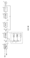
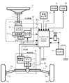
- the column shaft (steering shaft, handle shaft) 2 of the steering wheel 1 includes a speed reduction mechanism 3, universal joints 4a and 4b, a pinion rack mechanism 5, a tie rod 6a, 6b, and further connected to steering wheels 8L, 8R via hub units 7a, 7b. Further, the column shaft 2 having a torsion bar is provided with a torque sensor 10 for detecting a steering torque Ts of the steering wheel 1 and a steering angle sensor 14 for detecting a steering angle ⁇ h, and a motor for assisting the steering force of the steering wheel 1 is provided. 20 is connected to the column shaft 2 via the reduction mechanism 3.
- Electric power is supplied from the battery 13 to the control unit (ECU) 30 that controls the electric power steering device, and an ignition key signal is input via the ignition key 11.
- the control unit 30 calculates the current command value of the assist (steering assistance) command based on the steering torque Ts detected by the torque sensor 10 and the vehicle speed Vs detected by the vehicle speed sensor 12, and compensates for the current command value.
- the current supplied to the EPS motor 20 is controlled by the applied voltage control command value Vref.
- a CAN (Controller Area Network) 40 that exchanges various vehicle information is connected to the control unit 30, and the vehicle speed Vs can also be received from the CAN 40.
- the control unit 30 can also be connected to a non-CAN 41 other than the CAN 40 that exchanges communication, analog / digital signals, radio waves, and the like.
- the control unit 30 is mainly composed of a CPU (including MCU, MPU, etc.), and a general function executed by a program inside the CPU is shown in FIG.
- the function and operation of the control unit 30 will be described with reference to FIG. 2.
- the steering torque Ts detected by the torque sensor 10 and the vehicle speed Vs detected by the vehicle speed sensor 12 (or from the CAN 40) are the current command value calculation unit. 31 is input.
- the current command value calculation unit 31 calculates the current command value Iref1 which is the control target value of the current supplied to the motor 20, using the assist map and the like based on the input steering torque Ts and vehicle speed Vs.
- the voltage control command value Vref whose characteristics have been improved by the PI control unit 35 is input to the PWM control unit 36, and the motor 20 is PWM-driven via the inverter 37 as a drive unit.
- the current value Im of the motor 20 is detected by the motor current detector 38 and fed back to the subtraction unit 32B.
- the compensating signal CM from the compensating signal generating unit 34 is added to the adding unit 32A, and the characteristic of the steering system system is compensated by adding the compensating signal CM to improve the convergence and the inertia characteristic. ..
- the compensation signal generation unit 34 adds the self-aligning torque (SAT) 343 and the inertia 342 by the addition unit 344, further adds the convergence 341 to the addition result by the addition unit 345, and compensates the addition result by the addition unit 345. It is a signal CM.
- the steering torque applied by the driver's manual input is detected by the torque sensor as the torsion torque of the torsion bar, and the assist current corresponding to the torque is mainly detected. Is controlling the motor current.
- the steering torque may be different depending on the steering angle due to the difference in the road surface state (for example, inclination). Steering torque may also be affected by variations in motor output characteristics over time.
- Patent Document 1 an electric power steering device as disclosed in Japanese Patent No. 5208894 (Patent Document 1) has been proposed.
- the steering angle or the steering torque is determined based on the relationship between the steering angle or the steering torque and the response amount.
- the target value of the steering torque is set based on the relationship (steering reaction force characteristic map).
- the steering reaction force characteristic map must be obtained in advance, and the control is performed based on the deviation between the target value of the steering torque and the detected steering torque. Therefore, the influence on the steering torque may remain.
- the steering wheel may stop halfway without returning to the on-center, which may result in poor fit.
- a solution is also desired.
- the present invention has been made under the circumstances as described above, and an object of the present invention is not affected by the condition of the road surface, is not affected by the change in the mechanical characteristics of the steering system due to aging, and is effective for the steering angle and the like. It is an object of the present invention to provide a vehicle steering system capable of easily achieving an equivalent steering torque. Further, it is also an object to be able to return the handle after releasing it to the vicinity of the center.
- the present invention relates to a steering device for a vehicle, which includes at least a torsion bar having an arbitrary spring constant and a sensor for detecting a torsion angle of the torsion bar, and which assist-controls a steering system by driving and controlling a motor.
- the object of the above is to provide a target steering torque generator that generates a target steering torque, a converter that converts the target steering torque into a target twist angle, and a motor current that causes the twist angle to follow the target twist angle.
- a steering wheel return compensating section for calculating a first torque signal for compensating the steering wheel returning based on the steering torque and the first angular velocity information. It is achieved by outputting the first torque signal as the target steering torque and controlling the drive of the motor based on the motor current command value.
- the steering wheel return compensator uses a torque sensitive gain map to obtain a torque sensitive gain based on the magnitude of the steering torque, and a speed sensitive gain map.
- a speed sensitive gain unit that obtains a speed sensitive gain based on the magnitude of the first angular velocity information, and calculates the first torque signal from the torque sensitive gain, the speed sensitive gain, and the sign of the first angular velocity information.
- the torque-sensitive gain map has a characteristic that the torque-sensitive gain decreases as the steering torque increases, or the speed-sensitive gain map includes the first angular velocity information.
- the velocity sensitive gain increases as the magnitude of the first angular velocity information increases, and when the magnitude of the first angular velocity information exceeds the predetermined value, the The steering wheel return compensating unit further includes a limiting unit that limits the upper and lower limit values of the first torque signal by having a characteristic that the velocity sensitive gain decreases as the magnitude of the first angular velocity information increases.
- the target steering torque generation unit uses the basic map to obtain the second torque signal from the steering angle and the vehicle speed, and the damper gain map that is a vehicle speed response to obtain the second angular velocity information.
- the present invention further includes a damper calculation unit that obtains a third torque signal based on the steering state and the steering angle, and a hysteresis correction unit that obtains a fourth torque signal by performing hysteresis correction using the steering state and the steering angle.
- a target steering torque generation unit further includes a phase compensating unit that performs phase compensation in a front stage or a rear stage of the basic map unit, and the steering wheel is provided via the basic map unit and the phase compensating unit. This is achieved more effectively by obtaining the second torque signal from the angle and the vehicle speed.
- the twist angle follows the target twist angle by controlling the target twist angle obtained based on the target steering torque generated by the target steering torque generation unit.
- a desired steering torque can be realized, and an appropriate steering torque based on the driver's feeling of steering can be applied.
- the handle can be returned to the vicinity of the center when the handle is turned off and then released.
- FIG. 3 is a block diagram showing a configuration example (first embodiment) of a target steering torque generation unit. It is a diagram which shows the characteristic example of a basic map. It is a diagram which shows the characteristic example of a damper gain map. It is a diagram which shows the characteristic example of a hysteresis correction part. It is a block diagram showing an example of composition of a handle return compensation part.
- FIG. 5 is a flowchart showing an operation example (first embodiment) of the present invention.
- 6 is a flowchart showing an operation example (first embodiment) of a target steering torque generation unit. It is a flow chart which shows an example of operation of a twist angle control part. 6 is a graph showing an example of a time response of a steering angle and a steering torque when there is no steering wheel return compensation in a simulation showing an effect of a steering wheel return compensation unit.
- FIG. 6 is a graph showing an example of a time response of a steering angle and a steering torque when steering wheel return compensation is performed in a simulation showing an effect of a steering wheel return compensation unit.
- It is a block diagram which shows the structural example (2nd Embodiment) of a target steering torque production
- the present invention is a steering apparatus for a vehicle for realizing an equivalent steering torque with respect to a steering angle or the like without being affected by the state of the road surface, and a torsion angle of a torsion bar or the like is set to a value corresponding to the steering angle or the like.
- the desired steering torque is realized by controlling so as to follow.
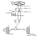
- FIG. 3 is a diagram showing an installation example of the EPS steering system and various sensors, and the column shaft 2 is provided with a torsion bar 2A.
- Road surface reaction force Fr and road surface information ⁇ act on the steered wheels 8L and 8R.
- An upper angle sensor is provided on the handle side of the column shaft 2 with the torsion bar 2A interposed therebetween, and a lower angle sensor is provided on the steering wheel side of the column shaft 2 with the torsion bar 2A interposed therebetween. Detects the steering wheel angle ⁇ 1 , and the lower angle sensor detects the column angle ⁇ 2 .
- the steering angle ⁇ h is detected by a steering angle sensor provided above the column shaft 2, and the twist angle ⁇ and the torsion bar torque of the torsion bar are calculated from the deviations of the steering wheel angle ⁇ 1 and the column angle ⁇ 2 according to the following formulas 1 and 2.
- Tt can be calculated.
- Kt is the spring constant of the torsion bar 2A.
- the torsion bar torque Tt can also be detected by using a torque sensor disclosed in JP 2008-216172 A, for example.
- the torsion bar torque Tt is also treated as the steering torque Ts.
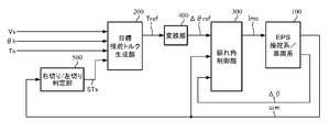
- FIG. 4 is a block diagram showing a configuration example (first embodiment) of the present invention, in which steering of a driver's steering wheel is assist-controlled by a motor in the EPS steering system / vehicle system 100.
- the target steering torque generation unit 200 that outputs the target steering torque Tref includes the vehicle speed Vs, the steering torque Ts, and the right-turn or left-turn steering state output from the right-turn / left-turn determination unit 500. STs is input.
- the target steering torque Tref is converted into a target twist angle ⁇ ref by the conversion unit 400, and the target twist angle ⁇ ref is input to the twist angle control unit 300 together with the twist angle ⁇ of the torsion bar 2A and the motor angular velocity ⁇ m.
- the twist angle control unit 300 calculates a motor current command value Imc such that the twist angle ⁇ becomes the target twist angle ⁇ ref, and the motor of the EPS is driven by the motor current command value Imc.
- the right-turn / left-turn determination unit 500 determines whether the steering is right-turn or left-turn based on the motor angular velocity ⁇ m, and outputs the determination result as the steering state STs. That is, when the motor angular velocity ⁇ m has a positive value, it is determined to be “right cut”, and when the motor angular velocity ⁇ m has a negative value, it is determined to be “left cut”. Instead of the motor angular velocity ⁇ m, an angular velocity calculated by performing a velocity calculation on the steering angle ⁇ h, the steering wheel angle ⁇ 1 or the column angle ⁇ 2 may be used.
- FIG. 5 shows a configuration example of the target steering torque generation unit 200.
- the target steering torque generation unit 200 includes a basic map unit 210, a differentiation unit 220, a damper gain unit 230, a hysteresis correction unit 240, a steering wheel return compensation unit 250, and a multiplication.
- the steering angle ⁇ h is input to the basic map unit 210, the differentiation unit 220, the hysteresis correction unit 240, and the steering wheel return compensation unit 250, and output from the right-turn / left-turn determination unit 500.
- the steering state STs is input to the hysteresis correction unit 240, the steering torque Ts is input to the steering wheel return compensation unit 250, and the vehicle speed Vs is input to the basic map unit 210 and the damper gain unit 230.
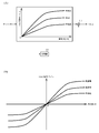
- the basic map unit 210 has a basic map and outputs a torque signal (second torque signal) Tref_a with the vehicle speed Vs as a parameter using the basic map.
- the basic map is adjusted by tuning. For example, as shown in FIG. 6A, the torque signal Tref_a increases as the magnitude (absolute value)
- the torque signal Tref_a is calculated by multiplying the calculated value by the sign of the steering angle ⁇ h.
- a map may be formed according to the positive and negative steering angles ⁇ h.
- the mode of change may be changed depending on whether the steering angle ⁇ h is positive or negative.
- the basic map shown in FIG. 6 is sensitive to vehicle speed, it may not be sensitive to vehicle speed.
- the differentiator 220 differentiates the steering angle ⁇ h to calculate the steering angular velocity ⁇ h that is the angular velocity information (second angular velocity information), and the steering angular velocity ⁇ h is input to the multiplier 270.
- the damper gain unit 230 outputs a damper gain D G by which the steering angular velocity ⁇ h is multiplied.
- the multiplication result of the steering angular velocity ⁇ h and the damper gain D G in the multiplication unit 270 is input to the addition unit 272 as a torque signal (third torque signal) Tref_b.
- the damper gain D G is obtained according to the vehicle speed Vs using the vehicle speed sensitive damper gain map included in the damper gain unit 230.
- the damper gain map has a characteristic of gradually increasing as the vehicle speed Vs increases, as shown in FIG. 7, for example.
- the damper gain map may be variable according to the steering angle ⁇ h.
- the damper gain unit 230 and the multiplication unit 270 form a damper calculation unit.
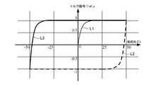
- the hysteresis correction unit 240 calculates the torque signal (fourth torque signal) Tref_c according to the following Expression 3 based on the steering angle ⁇ h and the steering state STs.
- x ⁇ h
- y Tref_c
- a> 1 c>
- a hys is a hysteresis width.
- the above formula 4 can be derived by substituting x1 for x and y1 for y R and y L in the above formula 3.
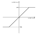
- An example diagram of the generated torque signal Tref_c is shown in FIG. That is, the torque signal Tref_c from the hysteresis correction unit 240 has hysteresis characteristics such as 0 origin ⁇ L1 (thin line) ⁇ L2 (broken line) ⁇ L3 (thick line).
- the coefficient A hys that represents the output width of the hysteresis characteristic and the coefficient c that represents roundness may be variable according to the vehicle speed Vs and / or the steering angle ⁇ h.
- the steering wheel return compensator 250 calculates a torque signal (first torque signal) Tref_d for compensating the steering wheel return.
- first torque signal first torque signal
- FIG. 9 shows a configuration example of the handle return compensation unit 250.
- the handle return compensation unit 250 includes a differentiating unit 251, absolute value units 252 and 253, a torque sensitive gain unit 254, a speed sensitive gain unit 255, a coding unit 256, multiplying units 260 and 261, a limiting unit 257, a filter unit 258, and a sign reversing unit.
- the unit 259 is provided.
- the differentiating part 251 differentiates the steering angle ⁇ h to calculate the steering angular speed ⁇ h1 which is the angular speed information (first angular speed information).
- the differentiating unit 220 may be shared and the differentiating unit 251 may be omitted.
- the absolute value units 252 and 253 output the magnitude (absolute value) of the input data.
- the absolute value unit 252 outputs the absolute value of the steering torque Ts, and the absolute value unit 253 outputs the absolute value of the steering angular velocity ⁇ h1. ..
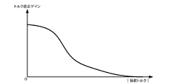
- the torque sensitive gain unit 254 obtains the torque sensitive gain Gt according to the absolute value of the steering torque Ts using the torque sensitive gain map.
- the torque sensitive gain map has a characteristic that the torque sensitive gain Gt gradually decreases as the absolute value of the steering torque Ts increases, as shown in FIG. 10, for example.
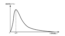
- the speed sensitive gain unit 255 obtains the speed sensitive gain Gv according to the absolute value of the steering angular speed ⁇ h1 using the speed sensitive gain map.
- the speed-sensitive gain map shows that the speed-sensitive gain Gv increases rapidly as the absolute value of the steering angular speed ⁇ h1 increases in the range of the absolute value of the steering angular speed ⁇ h1 from 0 to a predetermined value ⁇ 0.
- the steering angle velocity ⁇ h1 gradually decreases as the absolute value of the steering angular velocity ⁇ h1 increases.
- the sign unit 256 outputs the sign (+1, -1) of the steering angular velocity ⁇ h1.
- the limiting unit 257 limits the upper and lower limit values of the torque signal Tref_d0 calculated by multiplying the torque sensitive gain Gt, the speed sensitive gain Gv, and the sign of the steering angular velocity ⁇ h1, and outputs the torque signal Tref_d1.
- the upper limit value and the lower limit value for the torque signal are set in advance, and when the input torque signal Tref_d0 is the upper limit value or more, the upper limit value is set, and when the input torque signal Tref_d0 is the lower limit value or less, the lower limit value is set otherwise. In the case of, the torque signal Tref_d0 is output as the torque signal Tref_d1.
- the filter unit 258 reduces the high-frequency noise component included in the torque signal Tref_d1 by the filtering process using the low-pass filter (LPF), and outputs it as the torque signal Tref_d2.
- LPF low-pass filter
- the sign inversion unit 259 inverts the sign of the torque signal Tref_d2 and outputs it as the torque signal Tref_d.
- the characteristics of the torque sensitive gain map and the speed sensitive gain map are not limited to the curved characteristics shown in FIGS. 10 and 11, and may be linear characteristics or may be defined by a function.
- the limiting unit 257 can be omitted when the torque signal does not become an abnormal value, or when the output of the abnormal value is suppressed by other means, and when the high frequency noise is not superimposed on the torque signal or by other means.
- the filter unit 258 can be omitted when reducing high frequency noise.
- the torque signals Tref_d, Tref_c, Tref_b, and Tref_a obtained as described above are sequentially added by the adders 273, 272, and 271, and the final addition result is output as the target steering torque Tref.
- the steering angular velocities ⁇ h and ⁇ h1 calculated by the differentiating units 220 and 251 are obtained by a differential calculation with respect to the steering angle ⁇ h, but even if the LPF process is appropriately performed to reduce the influence of noise in the high range. Good (with respect to the steering angular velocity ⁇ h1 calculated by the differentiating unit 251, the LPF process does not have to be performed if the high-frequency noise reduction can be handled by the filter unit 258). Further, the differential calculation and the LPF processing may be performed using a high pass filter (HPF) and a gain.
- HPF high pass filter
- the steering angular velocities ⁇ h and ⁇ h1 are calculated not by the steering angle ⁇ h but by performing a differential calculation and LPF processing on the steering wheel angle ⁇ 1 detected by the upper angle sensor or the column angle ⁇ 2 detected by the lower angle sensor. You may. Instead of the steering angular velocities ⁇ h and ⁇ h1, the motor angular velocity ⁇ m may be used as the angular velocity information, and in this case, the differentiating units 220 and 251 are unnecessary.
- the conversion unit 400 has a characteristic of ⁇ 1 / Kt in which the sign of the reciprocal of the spring constant Kt of the torsion bar 2A is inverted, and converts the target steering torque Tref into the target twist angle ⁇ ref.
- the twist angle control unit 300 calculates the motor current command value Imc based on the target twist angle ⁇ ref, the twist angle ⁇ , and the motor angular velocity ⁇ m.
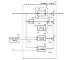
- FIG. 13 is a block diagram showing a configuration example of the torsion angle control unit 300.
- the torsion angle control unit 300 includes a torsion angle feedback (FB) compensation unit 310, a torsion angular velocity calculation unit 320, a velocity control unit 330, and a stabilization compensation unit.
- 340, an output limiting unit 350, a subtracting unit 361, and an adding unit 362 are provided.
- the target twist angle ⁇ ref output from the converting unit 400 is input to the subtracting unit 361, and the twist angle ⁇ is input to the subtracting unit 361.
- the motor angular velocity ⁇ m is input to the stabilization compensator 340.
- the torsion angle FB compensation unit 310 multiplies the target torsion angle ⁇ ref and the deviation ⁇ 0 of the torsion angle ⁇ calculated by the subtraction unit 361 by a compensation value C FB (transfer function), and the target torsion angle ⁇ ref is twisted by the torsion angle ⁇ . Outputs a target torsional angular velocity ⁇ ref that follows.
- the compensation value C FB may be a simple gain Kpp or a commonly used compensation value such as a PI control compensation value.
- the target twist angular velocity ⁇ ref is input to the velocity control unit 330.
- the twist angle FB compensator 310 and the speed controller 330 allow the twist angle ⁇ to follow the target twist angle ⁇ ref to realize a desired steering torque.
- the torsional angular velocity calculation unit 320 calculates the torsional angular velocity ⁇ t by performing a differential calculation on the torsional angle ⁇ , and the torsional angular velocity ⁇ t is input to the velocity control unit 330. Pseudo-differentiation using HPF and gain may be performed as the differential operation. Further, the twist angular velocity ⁇ t may be calculated by other means or other than the twist angle ⁇ and input to the velocity control unit 330.
- the speed control unit 330 calculates the motor current command value Imca1 by the IP control (proportional PI control) so that the torsional angular velocity ⁇ t follows the target torsional angular velocity ⁇ ref.
- the subtraction unit 333 calculates a difference ( ⁇ ref ⁇ t) between the target torsional angular velocity ⁇ ref and the torsional angular velocity ⁇ t, the integration unit 331 having a gain Kvi integrates the difference, and the integration result is added and input to the subtraction unit 334. It The torsional angular velocity ⁇ t is also input to the proportional section 332, subjected to proportional processing by the gain Kvp, and subtracted and input to the subtraction section 334.
- the subtraction result of the subtraction unit 334 is output as the motor current command value Imca1.
- the speed control unit 330 is not the IP control but the PI control, the P (proportional) control, the PID (proportional integral derivative) control, the PI-D control (differential preceding PID control), the model matching control, the model reference.
- the motor current command value Imca1 may be calculated by a generally used control method such as control.
- the stabilization compensator 340 has a compensation value Cs (transfer function), and calculates the motor current command value Imca2 from the motor angular velocity ⁇ m. If the gains of the torsion angle FB compensator 310 and the speed controller 330 are increased in order to improve the followability and the disturbance characteristics, a controllable oscillation phenomenon in a high range will occur. As a countermeasure against this, a transfer function (Cs) necessary for stabilizing the motor angular velocity ⁇ m is set in the stabilization compensating unit 340. As a result, stabilization of the entire EPS control system can be realized.
- the transfer function (Cs) of the stabilization compensating unit 340 for example, a first-order filter represented by the following formula 7 is set, which is set by a pseudo-differential using a first-order HPF structure and a gain.
- K sta is a gain
- fc is a center frequency
- fc is set to 150 [Hz]
- s is a Laplace operator.
- a secondary filter, a quaternary filter, or the like may be used as the transfer function.
- the motor current command value Imca1 from the speed control unit 330 and the motor current command value Imca2 from the stabilization compensating unit 340 are added by the adding unit 362 and output as the motor current command value Imcb.
- the output limiter 350 limits the upper and lower limits of the motor current command value Imcb and outputs the motor current command value Imc. Similar to the limiting unit 257 in the steering wheel return compensating unit 250, the upper limit value and the lower limit value for the motor current command value Imcb are set in advance and limited.
- the stabilization compensator may be omitted.
- the output limiting unit can also be omitted.
- the right-turn / left-turn determination unit 500 inputs the motor angular velocity ⁇ m, determines whether the steering is right-turn or left-turn based on the sign of the motor angular velocity ⁇ m, and sets the determination result as the steering state STs. It is output to the target steering torque generation unit 200 (step S10).
- the target steering torque generator 200 inputs the steering angle ⁇ h, the steering torque Ts, and the vehicle speed Vs together with the steering state STs, and generates the target steering torque Tref (step S20).
- An operation example of the target steering torque generation unit 200 will be described with reference to the flowchart in FIG.
- the steering angle ⁇ h input to the target steering torque generation unit 200 is input to the basic map unit 210, the differentiation unit 220, the hysteresis correction unit 240 and the steering wheel return compensation unit 250, the steering state STs is input to the hysteresis correction unit 240, and the steering torque Ts is input to the steering wheel Ts.
- the vehicle speed Vs is input to the return compensating unit 250 and to the basic map unit 210 and the damper gain unit 230 (step S21).
- the basic map unit 210 uses the basic map shown in FIG. 6A or 6B to generate a torque signal Tref_a corresponding to the steering angle ⁇ h and the vehicle speed Vs and outputs it to the addition unit 271 (step S22). ).
- the differentiating unit 220 differentiates the steering angle ⁇ h and outputs the steering angular velocity ⁇ h (step S23), and the damper gain unit 230 outputs the damper gain D G according to the vehicle speed Vs using the damper gain map shown in FIG. 7 (step S23).
- the multiplication unit 270 multiplies the steering angular velocity ⁇ h and the damper gain D G to calculate the torque signal Tref_b, and outputs the torque signal Tref_b to the addition unit 272 (step S25).
- the hysteresis correction unit 240 performs the hysteresis correction by switching the calculation according to Formula 5 and Formula 6 according to the steering state STs with respect to the steering angle ⁇ h (step S26), generates the torque signal Tref_c, and adds it to the addition unit 273. Output (step S27). Note that the hysteresis widths A hys , c, x1, and y1 in Equations 5 and 6 are set and held in advance, but b and b ′ are calculated in advance from Equation 6 and b and b ′ are used instead of x1 and y1. May be held.
- the steering wheel return compensation unit 250 inputs the input steering torque Ts and steering angle ⁇ h to the absolute unit 252 and the differentiation unit 251, respectively, and the differentiation unit 251 differentiates the steering angle ⁇ h to calculate the steering angular velocity ⁇ h1 (step S28). ), And the steering angular velocity ⁇ h1 is input to the absolute value unit 253 and the encoding unit 256.
- the absolute value unit 252 calculates the absolute value of the steering torque Ts and outputs it to the torque sensitive gain unit 254, and the absolute value unit 253 calculates the absolute value of the steering angular velocity ⁇ h1 and outputs it to the speed sensitive gain unit 255 (step S29). ).
- the torque sensitive gain unit 254 determines the torque sensitive gain Gt according to the absolute value of the steering torque Ts by using the torque sensitive gain map having the characteristics shown in FIG. 10 (step S30).
- the speed sensitive gain unit 255 determines the speed sensitive gain Gv according to the absolute value of the steering angular speed ⁇ h1 by using the speed sensitive gain map having the characteristics shown in FIG. 11 (step S31).
- the torque sensitive gain Gt and the speed sensitive gain Gv are multiplied by the multiplication unit 260 (step S32), and the multiplication result is multiplied by the sign of the steering angular velocity ⁇ h1 obtained by the encoding unit 256 in the multiplication unit 261 (step S33).
- the torque signal Tref_d0 is output.
- the torque signal Tref_d0 is input to the limiting unit 257, and the limiting unit 257 limits the upper and lower limit values of the torque signal Tref_d0 by the preset upper limit value and lower limit value, and outputs the torque signal Tref_d1 to the filter unit 258 (step S34). ..
- the filter unit 258 performs a filtering process on the torque signal Tref_d1 and outputs it as the torque signal Tref_d2 to the sign inverting unit 259 (step S35).
- the sign inversion unit 259 outputs the torque signal Tref_d, which is the inversion of the sign of the torque signal Tref_d2, to the addition unit 273 (step S36).
- the addition unit 273 adds the torque signals Tref_c and Tref_d
- the addition unit 272 adds the torque signal Tref_b to the addition result
- the addition unit 271 adds the torque signal Tref_a to the addition result.
- the steering torque Tref is calculated (step S37).
- the target steering torque Tref generated by the target steering torque generation unit 200 is input to the conversion unit 400 and converted into the target twist angle ⁇ ref by the conversion unit 400 (step S40).
- the target twist angle ⁇ ref is input to the twist angle control unit 300.
- the torsion angle control unit 300 inputs the torsion angle ⁇ and the motor angular velocity ⁇ m together with the target torsion angle ⁇ ref, and calculates the motor current command value Imc (step S50).
- An operation example of the torsion angle control unit 300 will be described with reference to the flowchart of FIG.
- the target twist angle ⁇ ref input to the twist angle control unit 300 is input to the subtraction unit 361, the twist angle ⁇ is input to the subtraction unit 361 and the twist angular velocity calculation unit 320, and the motor angular velocity ⁇ m is input to the stabilization compensation unit 340 (step S51).
- the subtraction unit 361 calculates the deviation ⁇ 0 by subtracting the twist angle ⁇ from the target twist angle ⁇ ref (step S52).
- Deviation [Delta] [theta] 0 is input to the helix angle FB compensation unit 310, the twist angle FB compensation unit 310 compensates the deviation [Delta] [theta] 0 is multiplied by the compensation value C FB on the deviation [Delta] [theta] 0 (step S53), the target torsion angular velocity ⁇ ref Is output to the speed control unit 330.
- the torsional angular velocity calculation unit 320 which has received the torsional angle ⁇ , calculates the torsional angular velocity ⁇ t by a differential calculation with respect to the torsion angle ⁇ (step S54), and outputs it to the velocity control unit 330.
- the difference between the target torsional angular velocity ⁇ ref and the torsional angular velocity ⁇ t is calculated by the subtracting unit 333, and the difference is integrated (Kvi / s) by the integrating unit 331 and added to the subtracting unit 334 (step S55).
- the twisting angular velocity ⁇ t is proportionally processed (Kvp) by the proportional portion 332, the proportional result is subtracted and input to the subtracting portion 334 (step S55), and the motor current command value Imca1 which is the subtracting result of the subtracting portion 334 is output and added. It is input to the unit 362.
- the stabilization compensator 340 performs stabilization compensation on the input motor angular velocity ⁇ m using the transfer function Cs represented by Expression 7 (step S56), and the motor current command value Imca2 from the stabilization compensator 340 is obtained. Is input to the addition unit 362.
- the addition unit 362 adds the motor current command values Imca1 and Imca2 (step S57), and the addition result motor current command value Imcb is input to the output limiting unit 350.
- the output limiter 350 limits the upper and lower limit values of the motor current command value Imcb by the preset upper limit value and lower limit value (step S58), and outputs the motor current command value Imc (step S59).
- the motor is driven based on the motor current command value Imc output from the torsion angle control unit 300, and current control is performed (step S60).
- the steering angle ⁇ h starts to operate in a state of about 60 deg, and the steering wheel return compensation unit performs steering wheel return compensation with and without steering wheel return compensation part 2 seconds after the operation is started.
- the time response of the upper angle of the torsion bar), the target steering torque, and the steering torque (torsion bar torque) is simulated.
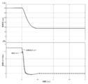
- FIG. 17 shows the simulation result when there is no steering wheel return compensation.
- 17A shows the time response of the steering angle
- FIG. 17B shows the time response of the target steering torque with a broken line and the time response of the steering torque with a solid line. From FIG. 17 (A), it can be seen that the steering angle is stopped at a position of about 17 deg after being released after 2 seconds from the start of the operation. This state is visually unpleasant to the driver and the vehicle deviates greatly from straight running, which is an unsuitable state in terms of safety.
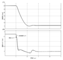
- FIG. 18 shows a simulation result in the case where there is steering wheel return compensation
- FIGS. 18A and 18B correspond to FIGS. 17A and 17B, respectively. From (A), it can be seen that the steering angle is improved to about 2 deg after the part is released. If improvements are made up to this point, it is possible to maintain a state similar to straight running, and the driver does not feel uncomfortable.
- the target steering torque generation unit 200 includes a basic map unit 210, a damper calculation unit (damper gain unit 230 and multiplication unit 270), a hysteresis correction unit 240, and a steering wheel return compensation unit 250. Only the handle return compensating section 250 may be specialized and only the handle return compensating section 250 may be provided.
- FIG. 19 shows a configuration example (second embodiment) of the target steering torque generation unit in this case.
- the torque signal Tref_d output from the steering wheel return compensation unit 250 is output as the target steering torque Tref.
- the target steering torque generation unit may be configured by combining at least one of the basic map unit 210, the damper calculation unit and the hysteresis correction unit 240, and the steering wheel return compensation unit 250.
- the motor current command value Imc output from the torsion angle control unit in the first and second embodiments is a current command value calculated based on the steering torque in the conventional EPS (hereinafter referred to as “assist current command value”). ) May be added to, for example, the current command value Iref1 output from the current command value calculation unit 31 shown in FIG. 2 or the current command value Iref2 obtained by adding the compensation signal CM to the current command value Iref1.
- FIG. 20 shows a configuration example (third embodiment) in which the above contents are applied to the first embodiment.
- the assist control unit 700 includes a current command value calculation unit 31, or a current command value calculation unit 31, a compensation signal generation unit 34, and an addition unit 32A.
- the assist current command value Iac output from the assist control unit 700 (corresponding to the current command value Iref1 or Iref2 in FIG. 2) and the motor current command value Imc output from the torsion angle control unit 300 are added by the addition unit 710.
- the current command value Ic that is the addition result is input to the current limiting unit 720, the motor is driven based on the current command value Icm in which the maximum current is limited, and the current control is performed.
- the phase compensating unit 280 that performs phase compensation may be inserted in the preceding stage or the subsequent stage of the basic map unit 210. That is, the configuration of the region R surrounded by the broken line in FIG. 5 may be configured as shown in FIG. 21 (A) or (B).
- the phase compensating unit 280 when phase lead compensation is set as the phase compensation and, for example, phase lead compensation is performed by a first-order filter with a numerator cutoff frequency of 1.0 Hz and a denominator cutoff frequency of 1.3 Hz, A refreshing feel can be realized.
- the target steering torque generation unit is not limited to the above configuration as long as it has a configuration based on the steering angle.
- the present invention is applied to a column type EPS, but the present invention is not limited to an upstream type such as a column type, but can also be applied to a downstream type EPS such as a rack and pinion.
- the feedback control based on the target twist angle can be applied to a steer-by-wire (SBW) reaction force device including at least a torsion bar (arbitrary spring constant) and a sensor for detecting a twist angle.
- SBW steer-by-wire
- An embodiment (fourth embodiment) in which the present invention is applied to an SBW reaction force device including a torsion bar will be described.
- FIG. 22 is a diagram showing a configuration example of the SBW system in correspondence with the general configuration of the electric power steering device shown in FIG. 1. The same components are designated by the same reference numerals, and detailed description will be omitted.
- the SBW system is a system that does not have an intermediate shaft mechanically coupled to the column shaft 2 by a universal joint 4a and transmits the operation of the steering wheel 1 to an steering mechanism including steering wheels 8L, 8R by an electric signal. ..
- the SBW system includes a reaction force device 60 and a drive device 70, and a control unit (ECU) 50 controls both devices.
- the reaction force device 60 detects the steering angle ⁇ h by the steering angle sensor 14, and at the same time transmits the motion state of the vehicle transmitted from the steered wheels 8L, 8R to the driver as reaction force torque.
- the reaction torque is generated by the reaction force motor 61.
- the SBW system to which the present invention is applied is a type having a torsion bar, and the torque sensor 10 detects the steering torque Ts. To do. Further, the angle sensor 74 detects the motor angle ⁇ m of the reaction force motor 61.
- the drive device 70 drives the drive motor 71 in accordance with the steering of the steering wheel 1 by the driver, applies the drive force to the pinion rack mechanism 5 via the gear 72, and operates it via the tie rods 6a and 6b. Steering wheels 8L and 8R are steered.
- An angle sensor 73 is arranged in the vicinity of the pinion rack mechanism 5 and detects the steering angle ⁇ t of the steered wheels 8L, 8R.
- the ECU 50 In order to control the reaction force device 60 and the drive device 70 in a coordinated manner, the ECU 50, based on the vehicle speed Vs from the vehicle speed sensor 12 and the like, in addition to the information such as the steering angle ⁇ h and the turning angle ⁇ t output from both devices, A voltage control command value Vref1 for driving and controlling the reaction force motor 61 and a voltage control command value Vref2 for driving and controlling the drive motor 71 are generated.
- FIG. 23 is a block diagram showing the configuration of the fourth embodiment.
- the twisting angle ⁇ is controlled (hereinafter referred to as “twisting angle control”) and the steering angle ⁇ t is controlled (hereinafter referred to as “steering angle control”) to twist the reaction force device.
- the drive device is controlled by the steering angle control.
- the drive device may be controlled by another control method.
- the twist angle ⁇ follows the target twist angle ⁇ ref calculated through the target steering torque generation unit 200 and the conversion unit 400 using the steering angle ⁇ h and the like by the same configuration and operation as in the first embodiment.
- the motor angle ⁇ m is detected by the angle sensor 74, and the motor angular velocity ⁇ m is calculated by differentiating the motor angle ⁇ m by the angular velocity calculator 951.
- the turning angle ⁇ t is detected by the angle sensor 73.
- the current control unit 130 includes the subtraction unit 32B, the PI control unit 35, and the PWM control shown in FIG.
- the reaction force motor 61 is driven to control the current.
- the target turning angle generation unit 910 In the turning angle control, the target turning angle generation unit 910 generates a target turning angle ⁇ tref based on the steering angle ⁇ h, and the target turning angle ⁇ tref is input to the turning angle control unit 920 together with the turning angle ⁇ t.
- the steering angle control unit 920 calculates the motor current command value Imct so that the steering angle ⁇ t becomes the target steering angle ⁇ tref. Then, based on the motor current command value Imct and the current value Imd of the drive motor 71 detected by the motor current detector 940, the current control unit 930 has the same configuration and operation as the current control unit 130, and the drive motor. 71 is driven to control the current.
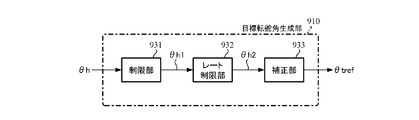
- FIG. 24 shows a configuration example of the target turning angle generation unit 910.
- the target turning angle generation unit 910 includes a limiting unit 931, a rate limiting unit 932, and a correcting unit 933.
- the limiter 931 limits the upper and lower limit values of the steering angle ⁇ h and outputs the steering angle ⁇ h1. Similar to the limiting unit 257 in the steering wheel return compensating unit 250 and the output limiting unit 350 in the torsion angle control unit 300, an upper limit value and a lower limit value for the steering angle ⁇ h are set in advance and are limited.
- the rate limiting unit 932 sets a limit value and limits the amount of change in the steering angle ⁇ h1 in order to avoid a sudden change in the steering angle, and outputs the steering angle ⁇ h2. For example, when the difference from the steering angle ⁇ h1 one sample before is set as the change amount, and the absolute value of the change amount is larger than a predetermined value (limit value), the steering angle is adjusted so that the absolute value of the change amount becomes the limit value. ⁇ h1 is added / subtracted and output as the steering angle ⁇ h2. When the steering angle ⁇ h1 is less than the limit value, the steering angle ⁇ h1 is output as the steering angle ⁇ h2. Note that instead of setting a limit value for the absolute value of the amount of change, it is also possible to set an upper limit value and a lower limit value for the amount of change to impose a limit. The rate may be limited.
- the correction unit 933 corrects the steering angle ⁇ h2 and outputs the target turning angle ⁇ tref. For example, like the basic map unit 210 in the target steering torque generation unit 200, using a map that defines the characteristics of the target turning angle ⁇ tref with respect to the magnitude
- FIG. 25 shows a configuration example of the steering angle control unit 920.
- the turning angle control unit 920 has the same configuration as the configuration example of the twist angle control unit 300 shown in FIG. 13 except for the stabilization compensating unit 340 and the adding unit 362, and has a target twist angle ⁇ ref and a twist.
- the target turning angle ⁇ tref and the turning angle ⁇ t are input instead of the angle ⁇ , and the turning angle feedback (FB) compensation unit 921, the turning angular velocity calculation unit 922, the speed control unit 923, the output limiting unit 926, and the subtraction unit 927.
- the torsion angle FB compensation unit 310, the torsion angular velocity calculation unit 320, the velocity control unit 330, the output limiting unit 350, and the subtraction unit 361 perform the same operation.
- the angle sensor 73 detects the steering angle ⁇ t
- the angle sensor 74 detects the motor angle ⁇ m (step S110)
- the steering angle ⁇ t is detected by the steering angle control unit 920
- the motor angle ⁇ m is measured by the angular velocity. It is input to each of the calculation units 951.
- the angular velocity calculation unit 951 differentiates the motor angle ⁇ m to calculate the motor angular velocity ⁇ m, and outputs the motor angular velocity ⁇ m to the right-turn / left-turn determination unit 500 (step S120).
- steps S10 to S60 shown in FIG. 14 After that, the same operation as steps S10 to S60 shown in FIG. 14 is performed, the reaction force motor 61 is driven, and the current control is performed (steps S130 to S170).
- the target turning angle generating unit 910 inputs the steering angle ⁇ h, and the steering angle ⁇ h is input to the limiting unit 931.
- the limiting unit 931 limits the upper and lower limit values of the steering angle ⁇ h by the preset upper limit value and lower limit value (step S180), and outputs the steering angle ⁇ h1 to the rate limiting unit 932.
- the rate limiting unit 932 limits the amount of change in the steering angle ⁇ h1 by a preset limit value (step S190), and outputs the steering angle ⁇ h2 to the correction unit 933.
- the correction unit 933 corrects the steering angle ⁇ h2 to obtain the target turning angle ⁇ tref (step S200), and outputs it to the turning angle control unit 920.
- the turning angle control unit 920 which has input the turning angle ⁇ t and the target turning angle ⁇ tref, calculates the deviation ⁇ t 0 by subtracting the turning angle ⁇ t from the target turning angle ⁇ tref in the subtracting unit 927 (step S210).
- Deviation Derutashitati 0 is input to the turning angle FB compensation unit 921, the turning angle FB compensation unit 921 compensates the deviation Derutashitati 0 by multiplying the compensation value to the deviation ⁇ t 0 (step S220), the target turning angular velocity ⁇ tref is output to the speed control unit 923.
- the steered angular velocity calculation unit 922 inputs the steered angle ⁇ t, calculates the steered angular velocity ⁇ tt by a differential calculation with respect to the steered angle ⁇ t (step S230), and outputs it to the speed control unit 923.
- the speed control unit 923 calculates the motor current command value Imcta by the IP control similarly to the speed control unit 330 (step S240) and outputs it to the output limiting unit 926.
- the output limiter 926 limits the upper and lower limits of the motor current command value Imcta by the preset upper and lower limits (step S250) and outputs the motor current command value Imct (step S260).
- the motor current command value Imct is input to the current control unit 930, and the current control unit 930 uses the motor current command value Imct and the current value Imd of the drive motor 71 detected by the motor current detector 940 to drive the motor. 71 is driven and a current control is implemented (step S270).
- the speed control unit 923 in the turning angle control unit 920 does not use the IP control, but the PI control, the P control, the PID control, and the PI-D, like the speed control unit 330 in the torsion angle control unit 300. Control, etc. are feasible and any control of P, I and D may be used, and the follow-up control by the steering angle control unit 920 and the twist angle control unit 300 is generally used. It may be performed with a control structure.
- the steered angle control unit 920 is used in a vehicle device as long as it has a control configuration in which the actual angle (here, the steered angle ⁇ t) follows the target angle (here, the target steered angle ⁇ tref).
- the control configuration is not limited, and for example, a control configuration used in an industrial positioning device, an industrial robot, or the like may be applied.
- one ECU 50 controls the reaction force device 60 and the drive device 70.
- the ECU for the reaction force device 60 and the ECU for the drive device 70 are respectively controlled. It may be provided.
- the ECUs exchange data with each other by communication.
- the SBW system shown in FIG. 22 does not have a mechanical connection between the reaction force device 60 and the drive device 70, but when an abnormality occurs in the system, the column shaft 2 and the steering mechanism are connected to a clutch or the like.
- the present invention can also be applied to an SBW system that includes a mechanical torque transmission mechanism that mechanically couples with each other. In such an SBW system, when the system is normal, the clutch is turned off to release the mechanical torque transmission, and when the system is abnormal, the clutch is turned on to enable the mechanical torque transmission.
- the torsion angle control unit 300 in the above-described first to fourth embodiments and the assist control unit 700 in the third embodiment directly calculate the motor current command value Imc and the assist current command value Iac, Before calculating them, the motor torque (target torque) desired to be output may be calculated first, and then the motor current command value and the assist current command value may be calculated. In this case, in order to obtain the motor current command value and the assist current command value from the motor torque, the generally used relationship between the motor current and the motor torque is used.
- a main object of the present invention is a means for realizing a target steering torque for performing steering wheel return compensation, and means for realizing the followability of the steering torque with respect to the target steering torque is limited to the above-mentioned converter and torsion angle controller. You don't have to.
Abstract
[Problem] To provide a vehicle steering device that can easily attain a steering torque equivalent to a steering angle or the like independently of the condition of a road surface and changes in mechanical characteristics of a steering system due to aging. Also, to return a steering wheel to a position near the center position after hands are off the steering wheel. [Solution] This vehicle steering device for carrying out assist control for a steering system comprises a target steering torque generation unit for generating a target steering torque, a conversion unit for converting the target steering torque into a target torsion angle, and a torsion angle control unit for calculating a motor current command value such that the torsion angle follows the target torsion angle, wherein the target steering torque generation unit is equipped with a steering wheel return compensation unit for calculating, on the basis of a steering torque and first angular velocity information, a first torque signal for compensating return of a steering wheel, outputs the first torque signal as a target steering torque, and controls driving of a motor on the basis of the motor current command value.
Description
本発明は、トーションバー等の捩れ角に基づいて所望の操舵トルクを実現し、路面の状態に影響されず、経年による機構系特性の変化に左右されない高性能な車両用操向装置に関する。
The present invention relates to a high-performance vehicle steering system that realizes a desired steering torque based on the torsion angle of a torsion bar or the like, is not affected by the state of the road surface, and is not affected by changes in mechanical system characteristics over time.
車両用操向装置の1つである電動パワーステアリング装置(EPS)は、車両の操舵系にモータの回転力でアシスト力(操舵補助力)を付与するものであり、インバータから供給される電力で制御されるモータの駆動力を、減速機構を含む伝達機構により、ステアリングシャフト或いはラック軸にアシスト力として付与する。かかる従来の電動パワーステアリング装置は、アシスト力を正確に発生させるため、モータ電流のフィードバック制御を行っている。フィードバック制御は、操舵補助指令値(電流指令値)とモータ電流検出値との差が小さくなるようにモータ印加電圧を調整するものであり、モータ印加電圧の調整は、一般的にPWM(パルス幅変調)制御のデューティの調整で行っている。
An electric power steering device (EPS), which is one of vehicle steering devices, applies an assist force (steering assist force) to a steering system of a vehicle by a rotational force of a motor, and uses electric power supplied from an inverter. The drive force of the controlled motor is applied as an assist force to the steering shaft or the rack shaft by the transmission mechanism including the speed reduction mechanism. Such a conventional electric power steering device performs feedback control of the motor current in order to accurately generate the assist force. The feedback control adjusts the motor applied voltage so that the difference between the steering assist command value (current command value) and the detected motor current value becomes small. The motor applied voltage is generally adjusted by PWM (pulse width). Modulation) control duty is adjusted.
電動パワーステアリング装置の一般的な構成を図1に示して説明すると、ハンドル1のコラム軸(ステアリングシャフト、ハンドル軸)2は減速機構3、ユニバーサルジョイント4a及び4b、ピニオンラック機構5、タイロッド6a,6bを経て、更にハブユニット7a,7bを介して操向車輪8L,8Rに連結されている。また、トーションバーを有するコラム軸2には、ハンドル1の操舵トルクTsを検出するトルクセンサ10及び操舵角θhを検出する舵角センサ14が設けられており、ハンドル1の操舵力を補助するモータ20が減速機構3を介してコラム軸2に連結されている。電動パワーステアリング装置を制御するコントロールユニット(ECU)30には、バッテリ13から電力が供給されると共に、イグニションキー11を経てイグニションキー信号が入力される。コントロールユニット30は、トルクセンサ10で検出された操舵トルクTsと車速センサ12で検出された車速Vsとに基づいてアシスト(操舵補助)指令の電流指令値の演算を行い、電流指令値に補償等を施した電圧制御指令値Vrefによって、EPS用モータ20に供給する電流を制御する。
The general structure of the electric power steering apparatus will be described with reference to FIG. 1. The column shaft (steering shaft, handle shaft) 2 of the steering wheel 1 includes a speed reduction mechanism 3, universal joints 4a and 4b, a pinion rack mechanism 5, a tie rod 6a, 6b, and further connected to steering wheels 8L, 8R via hub units 7a, 7b. Further, the column shaft 2 having a torsion bar is provided with a torque sensor 10 for detecting a steering torque Ts of the steering wheel 1 and a steering angle sensor 14 for detecting a steering angle θh, and a motor for assisting the steering force of the steering wheel 1 is provided. 20 is connected to the column shaft 2 via the reduction mechanism 3. Electric power is supplied from the battery 13 to the control unit (ECU) 30 that controls the electric power steering device, and an ignition key signal is input via the ignition key 11. The control unit 30 calculates the current command value of the assist (steering assistance) command based on the steering torque Ts detected by the torque sensor 10 and the vehicle speed Vs detected by the vehicle speed sensor 12, and compensates for the current command value. The current supplied to the EPS motor 20 is controlled by the applied voltage control command value Vref.
コントロールユニット30には、車両の各種情報を授受するCAN(Controller Area Network)40が接続されており、車速VsはCAN40から受信することも可能である。また、コントロールユニット30には、CAN40以外の通信、アナログ/ディジタル信号、電波等を授受する非CAN41も接続可能である。
A CAN (Controller Area Network) 40 that exchanges various vehicle information is connected to the control unit 30, and the vehicle speed Vs can also be received from the CAN 40. The control unit 30 can also be connected to a non-CAN 41 other than the CAN 40 that exchanges communication, analog / digital signals, radio waves, and the like.
コントロールユニット30は主としてCPU(MCU、MPU等も含む)で構成されるが、そのCPU内部においてプログラムで実行される一般的な機能を示すと図2のようになる。
The control unit 30 is mainly composed of a CPU (including MCU, MPU, etc.), and a general function executed by a program inside the CPU is shown in FIG.
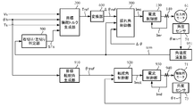
図2を参照してコントロールユニット30の機能及び動作を説明すると、トルクセンサ10で検出された操舵トルクTs及び車速センサ12で検出された(若しくはCAN40からの)車速Vsは、電流指令値演算部31に入力される。電流指令値演算部31は、入力された操舵トルクTs及び車速Vsに基づいてアシストマップ等を用いて、モータ20に供給する電流の制御目標値である電流指令値Iref1を演算する。電流指令値Iref1は加算部32Aを経て電流制限部33に入力され、最大電流を制限された電流指令値Irefmが減算部32Bに入力され、フィードバックされているモータ電流値Imとの偏差I(=Irefm-Im)が演算され、その偏差Iが操舵動作の特性改善のためのPI(比例積分)制御部35に入力される。PI制御部35で特性改善された電圧制御指令値VrefがPWM制御部36に入力され、更に駆動部としてのインバータ37を介してモータ20がPWM駆動される。モータ20の電流値Imはモータ電流検出器38で検出され、減算部32Bにフィードバックされる。
The function and operation of the control unit 30 will be described with reference to FIG. 2. The steering torque Ts detected by the torque sensor 10 and the vehicle speed Vs detected by the vehicle speed sensor 12 (or from the CAN 40) are the current command value calculation unit. 31 is input. The current command value calculation unit 31 calculates the current command value Iref1 which is the control target value of the current supplied to the motor 20, using the assist map and the like based on the input steering torque Ts and vehicle speed Vs. The current command value Iref1 is input to the current limiting unit 33 via the addition unit 32A, the current command value Irefm in which the maximum current is limited is input to the subtraction unit 32B, and the deviation I (= from the fed back motor current value Im Irefm-Im) is calculated, and the deviation I is input to the PI (proportional integral) control unit 35 for improving the characteristic of the steering operation. The voltage control command value Vref whose characteristics have been improved by the PI control unit 35 is input to the PWM control unit 36, and the motor 20 is PWM-driven via the inverter 37 as a drive unit. The current value Im of the motor 20 is detected by the motor current detector 38 and fed back to the subtraction unit 32B.
加算部32Aには補償信号生成部34からの補償信号CMが加算されており、補償信号CMの加算によって操舵システム系の特性補償を行い、収れん性や慣性特性等を改善するようになっている。補償信号生成部34は、セルフアライニングトルク(SAT)343と慣性342を加算部344で加算し、その加算結果に更に収れん性341を加算部345で加算し、加算部345の加算結果を補償信号CMとしている。
The compensating signal CM from the compensating signal generating unit 34 is added to the adding unit 32A, and the characteristic of the steering system system is compensated by adding the compensating signal CM to improve the convergence and the inertia characteristic. .. The compensation signal generation unit 34 adds the self-aligning torque (SAT) 343 and the inertia 342 by the addition unit 344, further adds the convergence 341 to the addition result by the addition unit 345, and compensates the addition result by the addition unit 345. It is a signal CM.
このように、従来の電動パワーステアリング装置でのアシスト制御では、運転者の手入力にて加えられた操舵トルクをトーションバーの捩れトルクとしてトルクセンサで検出し、主にそのトルクに応じたアシスト電流としてモータ電流を制御している。しかしながら、この方法で制御を行なう場合、路面の状態(例えば傾斜)の違いにより、操舵角によって異なる操舵トルクとなってしまうことがある。モータ出力特性の経年使用によるバラツキによっても、操舵トルクに影響を与えることがある。
As described above, in the assist control in the conventional electric power steering device, the steering torque applied by the driver's manual input is detected by the torque sensor as the torsion torque of the torsion bar, and the assist current corresponding to the torque is mainly detected. Is controlling the motor current. However, when the control is performed by this method, the steering torque may be different depending on the steering angle due to the difference in the road surface state (for example, inclination). Steering torque may also be affected by variations in motor output characteristics over time.
かかる問題を解決するために、例えば、特許第5208894号公報(特許文献1)に示されるような電動パワーステアリング装置が提案されている。特許文献1の電動パワーステアリング装置では、運転者の触覚特性に基づく適切な操舵トルクを与えるために、操舵角又は操舵トルクと手応え量との関係に基づいて決定される操舵角と操舵トルクとの関係(操舵反力特性マップ)に基づいて、操舵トルクの目標値を設定している。
In order to solve such a problem, for example, an electric power steering device as disclosed in Japanese Patent No. 5208894 (Patent Document 1) has been proposed. In the electric power steering device of Patent Document 1, in order to provide an appropriate steering torque based on the tactile characteristics of the driver, the steering angle or the steering torque is determined based on the relationship between the steering angle or the steering torque and the response amount. The target value of the steering torque is set based on the relationship (steering reaction force characteristic map).
しかしながら、特許文献1の電動パワーステアリング装置では、操舵反力特性マップを予め求めておかなければならず、また、操舵トルクの目標値と検出される操舵トルクとの偏差に基づいて制御を行っているので、操舵トルクに対する影響が残ってしまうおそれがある。
However, in the electric power steering apparatus of Patent Document 1, the steering reaction force characteristic map must be obtained in advance, and the control is performed based on the deviation between the target value of the steering torque and the detected steering torque. Therefore, the influence on the steering torque may remain.
一方、電動パワーステアリング装置によるアシスト制御では、ハンドルを切った状態から手放しを行った場合、ハンドルがオンセンタまで戻らずに途中で停止してしまい、収まりが悪くなってしまうことがあり、この問題の解決も望まれている。
On the other hand, in the assist control by the electric power steering device, if the steering wheel is released from the turned state, the steering wheel may stop halfway without returning to the on-center, which may result in poor fit. A solution is also desired.
本発明は上述のような事情よりなされたものであり、本発明の目的は、路面の状態に影響されず、経年によるステアリング操舵系の機構特性の変化に左右されず、操舵角等に対して同等の操舵トルクを容易に実現することが可能な車両用操向装置を提供することにある。更に、手放し後のハンドルをセンタ付近まで戻せるようにすることも目的である。
The present invention has been made under the circumstances as described above, and an object of the present invention is not affected by the condition of the road surface, is not affected by the change in the mechanical characteristics of the steering system due to aging, and is effective for the steering angle and the like. It is an object of the present invention to provide a vehicle steering system capable of easily achieving an equivalent steering torque. Further, it is also an object to be able to return the handle after releasing it to the vicinity of the center.
本発明は、任意のバネ定数を有するトーションバー及び前記トーションバーの捩れ角を検出するセンサを少なくとも備え、モータを駆動制御することにより、操舵系をアシスト制御する車両用操向装置に関し、本発明の上記目的は、目標操舵トルクを生成する目標操舵トルク生成部と、前記目標操舵トルクを目標捩れ角に変換する変換部と、前記目標捩れ角に対して前記捩れ角を追従させるようなモータ電流指令値を演算する捩れ角制御部とを備え、前記目標操舵トルク生成部が、操舵トルク及び第1角速度情報に基づいて、ハンドル戻りを補償する第1トルク信号を算出するハンドル戻り補償部を具備し、前記第1トルク信号を前記目標操舵トルクとして出力し、前記モータ電流指令値に基づいて前記モータを駆動制御することにより達成される。
The present invention relates to a steering device for a vehicle, which includes at least a torsion bar having an arbitrary spring constant and a sensor for detecting a torsion angle of the torsion bar, and which assist-controls a steering system by driving and controlling a motor. The object of the above is to provide a target steering torque generator that generates a target steering torque, a converter that converts the target steering torque into a target twist angle, and a motor current that causes the twist angle to follow the target twist angle. And a steering wheel return compensating section for calculating a first torque signal for compensating the steering wheel returning based on the steering torque and the first angular velocity information. It is achieved by outputting the first torque signal as the target steering torque and controlling the drive of the motor based on the motor current command value.
また、本発明の上記目的は、前記ハンドル戻り補償部が、トルク感応ゲインマップを用いて前記操舵トルクの大きさに基づいてトルク感応ゲインを求めるトルク感応ゲイン部と、速度感応ゲインマップを用いて前記第1角速度情報の大きさに基づいて速度感応ゲインを求める速度感応ゲイン部とを具備し、前記トルク感応ゲイン、前記速度感応ゲイン及び前記第1角速度情報の符号より前記第1トルク信号を算出することにより、或いは、前記トルク感応ゲインマップが、前記操舵トルクの大きさが大きくなるに従って前記トルク感応ゲインが小さくなる特性を有することにより、或いは、前記速度感応ゲインマップが、前記第1角速度情報の大きさがゼロから所定の値まででは、前記第1角速度情報の大きさが大きくなるに従って前記速度感応ゲインが大きくなり、前記第1角速度情報の大きさが前記所定の値を超えたら、前記第1角速度情報の大きさが大きくなるに従って前記速度感応ゲインが小さくなる特性を有することにより、或いは、前記ハンドル戻り補償部が、前記第1トルク信号の上下限値を制限する制限部を更に具備することにより、或いは、前記目標操舵トルク生成部が、基本マップを用いて操舵角及び車速より第2トルク信号を求める基本マップ部と、車速感応であるダンパゲインマップを用いて第2角速度情報に基づいて第3トルク信号を求めるダンパ演算部と、操舵状態及び前記操舵角を用いてヒステリシス補正を行って第4トルク信号を求めるヒステリシス補正部とを更に具備し、前記第2トルク信号、前記第3トルク信号及び前記第4トルク信号の内の少なくとも1つの信号並びに前記第1トルク信号より前記目標操舵トルクを算出することにより、或いは、前記基本マップ及び前記ヒステリシス補正部の特性が車速感応であることにより、或いは、前記目標操舵トルク生成部が、前記基本マップ部の前段又は後段に、位相補償を行なう位相補償部を更に具備し、前記基本マップ部及び前記位相補償部を介して、前記操舵角及び前記車速より前記第2トルク信号を求めることにより、より効果的に達成される。
Further, the above object of the present invention is that the steering wheel return compensator uses a torque sensitive gain map to obtain a torque sensitive gain based on the magnitude of the steering torque, and a speed sensitive gain map. A speed sensitive gain unit that obtains a speed sensitive gain based on the magnitude of the first angular velocity information, and calculates the first torque signal from the torque sensitive gain, the speed sensitive gain, and the sign of the first angular velocity information. Or the torque-sensitive gain map has a characteristic that the torque-sensitive gain decreases as the steering torque increases, or the speed-sensitive gain map includes the first angular velocity information. Is from zero to a predetermined value, the velocity sensitive gain increases as the magnitude of the first angular velocity information increases, and when the magnitude of the first angular velocity information exceeds the predetermined value, the The steering wheel return compensating unit further includes a limiting unit that limits the upper and lower limit values of the first torque signal by having a characteristic that the velocity sensitive gain decreases as the magnitude of the first angular velocity information increases. Alternatively, the target steering torque generation unit uses the basic map to obtain the second torque signal from the steering angle and the vehicle speed, and the damper gain map that is a vehicle speed response to obtain the second angular velocity information. The present invention further includes a damper calculation unit that obtains a third torque signal based on the steering state and the steering angle, and a hysteresis correction unit that obtains a fourth torque signal by performing hysteresis correction using the steering state and the steering angle. By calculating the target steering torque from at least one of the three torque signal and the fourth torque signal and the first torque signal, or the characteristics of the basic map and the hysteresis correction unit are vehicle speed responsiveness. Alternatively, the target steering torque generation unit further includes a phase compensating unit that performs phase compensation in a front stage or a rear stage of the basic map unit, and the steering wheel is provided via the basic map unit and the phase compensating unit. This is achieved more effectively by obtaining the second torque signal from the angle and the vehicle speed.
本発明の車両用操向装置によれば、目標操舵トルク生成部で生成される目標操舵トルクを基に求められる目標捩れ角に対して制御を行うことにより、目標捩れ角に捩れ角が追従するように動作し、所望の操舵トルクを実現し、運転者の操舵の感覚に基づく適切な操舵トルクを与えることができる。
According to the vehicle steering apparatus of the present invention, the twist angle follows the target twist angle by controlling the target twist angle obtained based on the target steering torque generated by the target steering torque generation unit. Thus, a desired steering torque can be realized, and an appropriate steering torque based on the driver's feeling of steering can be applied.
更に、ハンドル戻り補償部によるハンドル戻りの補償により、ハンドルを切った状態から手放しを行った場合、ハンドルをセンタ付近まで戻すことができる。
Furthermore, by compensating for the handle return by the handle return compensator, the handle can be returned to the vicinity of the center when the handle is turned off and then released.
本発明は、路面の状態に影響されず、操舵角等に対して同等の操舵トルクを実現するための車両用操向装置であり、トーションバー等の捩れ角を、操舵角等に応じた値に追従するように制御することにより所望の操舵トルクを実現している。
The present invention is a steering apparatus for a vehicle for realizing an equivalent steering torque with respect to a steering angle or the like without being affected by the state of the road surface, and a torsion angle of a torsion bar or the like is set to a value corresponding to the steering angle or the like. The desired steering torque is realized by controlling so as to follow.
以下に、本発明の実施の形態を、図面を参照して説明する。
Embodiments of the present invention will be described below with reference to the drawings.
先ず、本発明に係る車両用操向装置の1つである電動パワーステアリング装置に関連する情報を検出する各種センサの設置例について説明する。図3は、EPS操舵系と各種センサの設置例を示す図であり、コラム軸2にはトーションバー2Aが備えられている。操向車輪8L,8Rには路面反力Fr及び路面情報μが作用する。トーションバー2Aを挟んでコラム軸2のハンドル側には上側角度センサが設けられ、トーションバー2Aを挟んでコラム軸2の操向車輪側には下側角度センサが設けられており、上側角度センサはハンドル角θ1を検出し、下側角度センサはコラム角θ2を検出する。操舵角θhはコラム軸2の上部に設けられた舵角センサで検出され、ハンドル角θ1及びコラム角θ2の偏差から、下記数1及び数2によってトーションバーの捩れ角Δθ及びトーションバートルクTtを求めることができる。なお、Ktはトーションバー2Aのバネ定数である。
First, an example of installation of various sensors that detect information related to an electric power steering device that is one of the vehicle steering systems according to the present invention will be described. FIG. 3 is a diagram showing an installation example of the EPS steering system and various sensors, and the column shaft 2 is provided with a torsion bar 2A. Road surface reaction force Fr and road surface information μ act on the steered wheels 8L and 8R. An upper angle sensor is provided on the handle side of the column shaft 2 with the torsion bar 2A interposed therebetween, and a lower angle sensor is provided on the steering wheel side of the column shaft 2 with the torsion bar 2A interposed therebetween. Detects the steering wheel angle θ 1 , and the lower angle sensor detects the column angle θ 2 . The steering angle θh is detected by a steering angle sensor provided above the column shaft 2, and the twist angle Δθ and the torsion bar torque of the torsion bar are calculated from the deviations of the steering wheel angle θ 1 and the column angle θ 2 according to the following formulas 1 and 2. Tt can be calculated. Note that Kt is the spring constant of the torsion bar 2A.
次に、本発明の構成例について説明する。
Next, a configuration example of the present invention will be described.
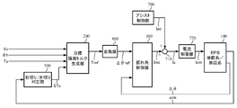
図4は本発明の構成例(第1実施形態)を示すブロック図であり、運転者のハンドル操舵はEPS操舵系/車両系100内のモータでアシスト制御される。目標操舵トルクTrefを出力する目標操舵トルク生成部200には、操舵角θhの他に、車速Vs、操舵トルクTs及び右切り/左切り判定部500から出力される右切り又は左切りの操舵状態STsが入力される。目標操舵トルクTrefは変換部400で目標捩れ角Δθrefに変換され、目標捩れ角Δθrefは、トーションバー2Aの捩れ角Δθ及びモータ角速度ωmと共に捩れ角制御部300に入力される。捩れ角制御部300は、捩れ角Δθが目標捩れ角Δθrefとなるようなモータ電流指令値Imcを演算し、モータ電流指令値ImcによりEPSのモータが駆動される。
FIG. 4 is a block diagram showing a configuration example (first embodiment) of the present invention, in which steering of a driver's steering wheel is assist-controlled by a motor in the EPS steering system / vehicle system 100. In addition to the steering angle θh, the target steering torque generation unit 200 that outputs the target steering torque Tref includes the vehicle speed Vs, the steering torque Ts, and the right-turn or left-turn steering state output from the right-turn / left-turn determination unit 500. STs is input. The target steering torque Tref is converted into a target twist angle Δθref by the conversion unit 400, and the target twist angle Δθref is input to the twist angle control unit 300 together with the twist angle Δθ of the torsion bar 2A and the motor angular velocity ωm. The twist angle control unit 300 calculates a motor current command value Imc such that the twist angle Δθ becomes the target twist angle Δθref, and the motor of the EPS is driven by the motor current command value Imc.
右切り/左切り判定部500は、モータ角速度ωmを基に操舵が右切りか左切りかを判定し、判定結果を操舵状態STsとして出力する。即ち、モータ角速度ωmが正の値の場合は「右切り」と判定し、負の値の場合は「左切り」と判定する。なお、モータ角速度ωmの代わりに、操舵角θh、ハンドル角θ1又はコラム角θ2に対して速度演算を行って算出される角速度を用いても良い。
The right-turn / left-turn determination unit 500 determines whether the steering is right-turn or left-turn based on the motor angular velocity ωm, and outputs the determination result as the steering state STs. That is, when the motor angular velocity ωm has a positive value, it is determined to be “right cut”, and when the motor angular velocity ωm has a negative value, it is determined to be “left cut”. Instead of the motor angular velocity ωm, an angular velocity calculated by performing a velocity calculation on the steering angle θh, the steering wheel angle θ 1 or the column angle θ 2 may be used.
図5は目標操舵トルク生成部200の構成例を示しており、目標操舵トルク生成部200は、基本マップ部210、微分部220、ダンパゲイン部230、ヒステリシス補正部240、ハンドル戻り補償部250、乗算部270並びに加算部271、272及び273を備え、操舵角θhは基本マップ部210、微分部220、ヒステリシス補正部240及びハンドル戻り補償部250に入力され、右切り/左切り判定部500から出力される操舵状態STsはヒステリシス補正部240に入力され、操舵トルクTsはハンドル戻り補償部250に入力され、車速Vsは基本マップ部210及びダンパゲイン部230に入力される。
FIG. 5 shows a configuration example of the target steering torque generation unit 200. The target steering torque generation unit 200 includes a basic map unit 210, a differentiation unit 220, a damper gain unit 230, a hysteresis correction unit 240, a steering wheel return compensation unit 250, and a multiplication. The steering angle θh is input to the basic map unit 210, the differentiation unit 220, the hysteresis correction unit 240, and the steering wheel return compensation unit 250, and output from the right-turn / left-turn determination unit 500. The steering state STs is input to the hysteresis correction unit 240, the steering torque Ts is input to the steering wheel return compensation unit 250, and the vehicle speed Vs is input to the basic map unit 210 and the damper gain unit 230.
基本マップ部210は、基本マップを有し、基本マップを用いて、車速Vsをパラメータとするトルク信号(第2トルク信号)Tref_aを出力する。基本マップはチューニングにより調整されており、例えば、図6(A)に示されるように、トルク信号Tref_aは、操舵角θhの大きさ(絶対値)|θh|が増加するにつれて増加し、車速Vsが増加するにつれて増加するようになっている。なお、図6(A)において、符号部211は操舵角θhの符号(+1、-1)を乗算部212に出力しており、操舵角θhの大きさからマップによりトルク信号Tref_aの大きさを求め、これに操舵角θhの符号を乗算し、トルク信号Tref_aを求める構成となっているが、図6(B)に示されるように、正負の操舵角θhに応じてマップを構成しても良く、この場合、操舵角θhが正の場合と負の場合とで変化の態様を変えても良い。また、図6に示される基本マップは車速感応であるが、車速感応でなくても良い。
The basic map unit 210 has a basic map and outputs a torque signal (second torque signal) Tref_a with the vehicle speed Vs as a parameter using the basic map. The basic map is adjusted by tuning. For example, as shown in FIG. 6A, the torque signal Tref_a increases as the magnitude (absolute value) | θh | of the steering angle θh increases, and the vehicle speed Vs increases. Is increasing as is increased. Note that, in FIG. 6A, the sign unit 211 outputs the sign (+1, −1) of the steering angle θh to the multiplication unit 212, and the magnitude of the steering angle θh indicates the magnitude of the torque signal Tref_a from the map. The torque signal Tref_a is calculated by multiplying the calculated value by the sign of the steering angle θh. However, as shown in FIG. 6B, a map may be formed according to the positive and negative steering angles θh. Of course, in this case, the mode of change may be changed depending on whether the steering angle θh is positive or negative. Further, although the basic map shown in FIG. 6 is sensitive to vehicle speed, it may not be sensitive to vehicle speed.
微分部220は、操舵角θhを微分して角速度情報(第2角速度情報)である舵角速度ωhを算出し、舵角速度ωhは乗算部270に入力される。
The differentiator 220 differentiates the steering angle θh to calculate the steering angular velocity ωh that is the angular velocity information (second angular velocity information), and the steering angular velocity ωh is input to the multiplier 270.
ダンパゲイン部230は、舵角速度ωhに乗算されるダンパゲインDGを出力する。乗算部270における舵角速度ωh及びダンパゲインDGの乗算結果は、トルク信号(第3トルク信号)Tref_bとして加算部272に入力される。ダンパゲインDGは、ダンパゲイン部230が有する車速感応型のダンパゲインマップを用いて、車速Vsに応じて求められる。ダンパゲインマップは、例えば、図7に示されるように、車速Vsが高くなるに従って徐々に大きくなる特性を有する。ダンパゲインマップは操舵角θhに応じて可変としても良い。なお、ダンパゲイン部230及び乗算部270でダンパ演算部を構成している。
The damper gain unit 230 outputs a damper gain D G by which the steering angular velocity ωh is multiplied. The multiplication result of the steering angular velocity ωh and the damper gain D G in the multiplication unit 270 is input to the addition unit 272 as a torque signal (third torque signal) Tref_b. The damper gain D G is obtained according to the vehicle speed Vs using the vehicle speed sensitive damper gain map included in the damper gain unit 230. The damper gain map has a characteristic of gradually increasing as the vehicle speed Vs increases, as shown in FIG. 7, for example. The damper gain map may be variable according to the steering angle θh. The damper gain unit 230 and the multiplication unit 270 form a damper calculation unit.
ヒステリシス補正部240は操舵角θh及び操舵状態STsに基づき、下記数3に従ってトルク信号(第4トルク信号)Tref_cを演算する。なお、下記数3では、x=θh、y=Tref_cとしており、a>1、c>0であり、Ahysはヒステリシス幅である。
The hysteresis correction unit 240 calculates the torque signal (fourth torque signal) Tref_c according to the following Expression 3 based on the steering angle θh and the steering state STs. In the following Expression 3, x = θh, y = Tref_c, a> 1, c> 0, and A hys is a hysteresis width.


“a”として1より大きい任意の正数を用いることができ、例えば、ネイピア数“e”を用いた場合、数3及び数4は下記数5及び数6となる。
An arbitrary positive number larger than 1 can be used as “a”. For example, when the Napier number “e” is used, the expressions 3 and 4 become the following expressions 5 and 6, respectively.


なお、ヒステリシス特性の出力幅を表す係数であるAhys及び丸みを表す係数であるcを、車速Vs及び/又は操舵角θhに応じて可変としても良い。
It should be noted that the coefficient A hys that represents the output width of the hysteresis characteristic and the coefficient c that represents roundness may be variable according to the vehicle speed Vs and / or the steering angle θh.
ハンドル戻り補償部250は、ハンドル戻りを補償するためのトルク信号(第1トルク信号)Tref_dを算出する。ハンドルを切った状態からハンドルを手放した場合、ハンドルがオンセンタまで戻らずに途中で停止してしまうことがあるので、ハンドルをセンタ付近まで戻すためのトルク信号Tref_dを算出する。
The steering wheel return compensator 250 calculates a torque signal (first torque signal) Tref_d for compensating the steering wheel return. When the handle is released from the turned state, the handle may stop halfway without returning to the on-center, so the torque signal Tref_d for returning the handle to near the center is calculated.
ハンドル戻り補償部250の構成例を図9に示す。ハンドル戻り補償部250は、微分部251、絶対値部252及び253、トルク感応ゲイン部254、速度感応ゲイン部255、符号部256、乗算部260及び261、制限部257、フィルタ部258並びに符号反転部259を備える。
FIG. 9 shows a configuration example of the handle return compensation unit 250. The handle return compensation unit 250 includes a differentiating unit 251, absolute value units 252 and 253, a torque sensitive gain unit 254, a speed sensitive gain unit 255, a coding unit 256, multiplying units 260 and 261, a limiting unit 257, a filter unit 258, and a sign reversing unit. The unit 259 is provided.
微分部251は、微分部220と同様に、操舵角θhを微分して角速度情報(第1角速度情報)である舵角速度ωh1を算出する。なお、微分部220を共用して、微分部251を省略しても良い。
Like the differentiating part 220, the differentiating part 251 differentiates the steering angle θh to calculate the steering angular speed ωh1 which is the angular speed information (first angular speed information). The differentiating unit 220 may be shared and the differentiating unit 251 may be omitted.
絶対値部252及び253は入力データの大きさ(絶対値)を出力するもので、絶対値部252は操舵トルクTsの絶対値を、絶対値部253は舵角速度ωh1の絶対値をそれぞれ出力する。
The absolute value units 252 and 253 output the magnitude (absolute value) of the input data. The absolute value unit 252 outputs the absolute value of the steering torque Ts, and the absolute value unit 253 outputs the absolute value of the steering angular velocity ωh1. ..
トルク感応ゲイン部254は、トルク感応ゲインマップを用いて、操舵トルクTsの絶対値に応じたトルク感応ゲインGtを求める。トルク感応ゲインマップは、例えば図10に示されるように、トルク感応ゲインGtが、操舵トルクTsの絶対値が大きくなるに従って徐々に小さくなる特性を有する。
The torque sensitive gain unit 254 obtains the torque sensitive gain Gt according to the absolute value of the steering torque Ts using the torque sensitive gain map. The torque sensitive gain map has a characteristic that the torque sensitive gain Gt gradually decreases as the absolute value of the steering torque Ts increases, as shown in FIG. 10, for example.
速度感応ゲイン部255は、速度感応ゲインマップを用いて、舵角速度ωh1の絶対値に応じた速度感応ゲインGvを求める。速度感応ゲインマップは、例えば図11に示されるように、速度感応ゲインGvが、舵角速度ωh1の絶対値が0から所定の値ω0までの範囲では、舵角速度ωh1の絶対値が大きくなるに従って急速に大きくなり、所定の値ω0を超えた範囲では、舵角速度ωh1の絶対値が大きくなるに従って徐々に小さくなる特性を有する。
The speed sensitive gain unit 255 obtains the speed sensitive gain Gv according to the absolute value of the steering angular speed ωh1 using the speed sensitive gain map. For example, as shown in FIG. 11, the speed-sensitive gain map shows that the speed-sensitive gain Gv increases rapidly as the absolute value of the steering angular speed ωh1 increases in the range of the absolute value of the steering angular speed ωh1 from 0 to a predetermined value ω0. In the range in which the steering angular velocity ωh1 increases, the steering angle velocity ωh1 gradually decreases as the absolute value of the steering angular velocity ωh1 increases.
符号部256は舵角速度ωh1の符号(+1、-1)を出力する。
The sign unit 256 outputs the sign (+1, -1) of the steering angular velocity ωh1.
制限部257は、トルク感応ゲインGt、速度感応ゲインGv及び舵角速度ωh1の符号を乗算して算出されるトルク信号Tref_d0の上下限値を制限して、トルク信号Tref_d1を出力する。トルク信号Tref_d0の上下限値を制限することにより、異常値の出力を抑える。図12に示されるように、トルク信号に対する上限値及び下限値を予め設定し、入力するトルク信号Tref_d0が、上限値以上の場合は上限値を、下限値以下の場合は下限値を、それ以外の場合はトルク信号Tref_d0を、トルク信号Tref_d1として出力する。
The limiting unit 257 limits the upper and lower limit values of the torque signal Tref_d0 calculated by multiplying the torque sensitive gain Gt, the speed sensitive gain Gv, and the sign of the steering angular velocity ωh1, and outputs the torque signal Tref_d1. By limiting the upper and lower limit values of the torque signal Tref_d0, the output of abnormal values is suppressed. As shown in FIG. 12, the upper limit value and the lower limit value for the torque signal are set in advance, and when the input torque signal Tref_d0 is the upper limit value or more, the upper limit value is set, and when the input torque signal Tref_d0 is the lower limit value or less, the lower limit value is set otherwise. In the case of, the torque signal Tref_d0 is output as the torque signal Tref_d1.
フィルタ部258は、ローパスフィルタ(LPF)によるフィルタ処理により、トルク信号Tref_d1に含まれる高域のノイズ成分を低減し、トルク信号Tref_d2として出力する。
The filter unit 258 reduces the high-frequency noise component included in the torque signal Tref_d1 by the filtering process using the low-pass filter (LPF), and outputs it as the torque signal Tref_d2.
符号反転部259は、トルク信号Tref_d2の符号を反転し、トルク信号Tref_dとして出力する。
The sign inversion unit 259 inverts the sign of the torque signal Tref_d2 and outputs it as the torque signal Tref_d.
なお、トルク感応ゲインマップ及び速度感応ゲインマップの特性は、図10及び図11に示されるような曲線的な特性に限られず、直線的な特性でも良く、関数で特性を定義しても良い。また、トルク信号が異常値とならない場合や、他の手段で異常値の出力を抑える場合等では制限部257は省略可能であり、トルク信号に高域ノイズが重畳しない場合や、他の手段で高域ノイズを低減する場合等ではフィルタ部258は省略可能である。
The characteristics of the torque sensitive gain map and the speed sensitive gain map are not limited to the curved characteristics shown in FIGS. 10 and 11, and may be linear characteristics or may be defined by a function. Further, the limiting unit 257 can be omitted when the torque signal does not become an abnormal value, or when the output of the abnormal value is suppressed by other means, and when the high frequency noise is not superimposed on the torque signal or by other means. The filter unit 258 can be omitted when reducing high frequency noise.
上述のように求められたトルク信号Tref_d、Tref_c、Tref_b及びTref_aは、加算部273、272及び271で順次加算されていき、最終の加算結果が目標操舵トルクTrefとして出力される。
The torque signals Tref_d, Tref_c, Tref_b, and Tref_a obtained as described above are sequentially added by the adders 273, 272, and 271, and the final addition result is output as the target steering torque Tref.
なお、微分部220及び251で算出される舵角速度ωh及びωh1は、操舵角θhに対する微分演算により求めているが、高域のノイズの影響を低減するために適度にLPF処理を実施しても良い(微分部251で算出される舵角速度ωh1に関しては、この高域ノイズ低減をフィルタ部258で対応可能な場合、LPF処理を実施しなくても良い)。また、ハイパスフィルタ(HPF)とゲインにより、微分演算とLPFの処理を実施しても良い。更に、舵角速度ωh及びωh1は、操舵角θhではなく、上側角度センサが検出するハンドル角θ1又は下側角度センサが検出するコラム角θ2に対して微分演算とLPFの処理を行って算出しても良い。舵角速度ωh及びωh1の代わりにモータ角速度ωmを角速度情報として使用しても良く、この場合、微分部220及び251は不要となる。
The steering angular velocities ωh and ωh1 calculated by the differentiating units 220 and 251 are obtained by a differential calculation with respect to the steering angle θh, but even if the LPF process is appropriately performed to reduce the influence of noise in the high range. Good (with respect to the steering angular velocity ωh1 calculated by the differentiating unit 251, the LPF process does not have to be performed if the high-frequency noise reduction can be handled by the filter unit 258). Further, the differential calculation and the LPF processing may be performed using a high pass filter (HPF) and a gain. Further, the steering angular velocities ωh and ωh1 are calculated not by the steering angle θh but by performing a differential calculation and LPF processing on the steering wheel angle θ 1 detected by the upper angle sensor or the column angle θ 2 detected by the lower angle sensor. You may. Instead of the steering angular velocities ωh and ωh1, the motor angular velocity ωm may be used as the angular velocity information, and in this case, the differentiating units 220 and 251 are unnecessary.
変換部400は、トーションバー2Aのバネ定数Ktの逆数の符号を反転した-1/Ktの特性を有しており、目標操舵トルクTrefを目標捩れ角Δθrefに変換する。
The conversion unit 400 has a characteristic of −1 / Kt in which the sign of the reciprocal of the spring constant Kt of the torsion bar 2A is inverted, and converts the target steering torque Tref into the target twist angle Δθref.
捩れ角制御部300は、目標捩れ角Δθref、捩れ角Δθ及びモータ角速度ωmに基づいてモータ電流指令値Imcを演算する。図13は捩れ角制御部300の構成例を示すブロック図であり、捩れ角制御部300は、捩れ角フィードバック(FB)補償部310、捩れ角速度演算部320、速度制御部330、安定化補償部340、出力制限部350、減算部361及び加算部362を備えており、変換部400から出力される目標捩れ角Δθrefは減算部361に加算入力され、捩れ角Δθは減算部361に減算入力されると共に、捩れ角速度演算部320に入力され、モータ角速度ωmは安定化補償部340に入力される。
The twist angle control unit 300 calculates the motor current command value Imc based on the target twist angle Δθref, the twist angle Δθ, and the motor angular velocity ωm. FIG. 13 is a block diagram showing a configuration example of the torsion angle control unit 300. The torsion angle control unit 300 includes a torsion angle feedback (FB) compensation unit 310, a torsion angular velocity calculation unit 320, a velocity control unit 330, and a stabilization compensation unit. 340, an output limiting unit 350, a subtracting unit 361, and an adding unit 362 are provided. The target twist angle Δθref output from the converting unit 400 is input to the subtracting unit 361, and the twist angle Δθ is input to the subtracting unit 361. The motor angular velocity ωm is input to the stabilization compensator 340.
捩れ角FB補償部310は、減算部361で算出される目標捩れ角Δθrefと捩れ角Δθの偏差Δθ0に対して補償値CFB(伝達関数)を乗算し、目標捩れ角Δθrefに捩れ角Δθが追従するような目標捩れ角速度ωrefを出力する。補償値CFBは単純なゲインKppでも、PI制御の補償値など一般的に用いられている補償値でも良い。目標捩れ角速度ωrefは速度制御部330に入力される。捩れ角FB補償部310と速度制御部330により、目標捩れ角Δθrefに捩れ角Δθを追従させ、所望の操舵トルクを実現することが可能となる。
The torsion angle FB compensation unit 310 multiplies the target torsion angle Δθref and the deviation Δθ 0 of the torsion angle Δθ calculated by the subtraction unit 361 by a compensation value C FB (transfer function), and the target torsion angle Δθref is twisted by the torsion angle Δθ. Outputs a target torsional angular velocity ωref that follows. The compensation value C FB may be a simple gain Kpp or a commonly used compensation value such as a PI control compensation value. The target twist angular velocity ωref is input to the velocity control unit 330. The twist angle FB compensator 310 and the speed controller 330 allow the twist angle Δθ to follow the target twist angle Δθref to realize a desired steering torque.
捩れ角速度演算部320は、捩れ角Δθに対する微分演算により捩れ角速度ωtを算出し、捩れ角速度ωtは速度制御部330に入力される。微分演算として、HPFとゲインによる擬似微分を行なっても良い。また、捩れ角速度ωtを別の手段や捩れ角Δθ以外から算出し、速度制御部330に入力するようにしても良い。
The torsional angular velocity calculation unit 320 calculates the torsional angular velocity ωt by performing a differential calculation on the torsional angle Δθ, and the torsional angular velocity ωt is input to the velocity control unit 330. Pseudo-differentiation using HPF and gain may be performed as the differential operation. Further, the twist angular velocity ωt may be calculated by other means or other than the twist angle Δθ and input to the velocity control unit 330.
速度制御部330は、I-P制御(比例先行型PI制御)により、目標捩れ角速度ωrefに捩れ角速度ωtが追従するようなモータ電流指令値Imca1を算出する。減算部333で目標捩れ角速度ωrefと捩れ角速度ωtとの差分(ωref-ωt)を算出し、その差分を、ゲインKviを有する積分部331にて積分し、積分結果は減算部334に加算入力される。捩れ角速度ωtは比例部332にも入力され、ゲインKvpによる比例処理を施され、減算部334に減算入力される。減算部334での減算結果がモータ電流指令値Imca1として出力される。なお、速度制御部330は、I-P制御ではなく、PI制御、P(比例)制御、PID(比例積分微分)制御、PI-D制御(微分先行型PID制御)、モデルマッチング制御、モデル規範制御等の一般的に用いられている制御方法でモータ電流指令値Imca1を算出しても良い。
The speed control unit 330 calculates the motor current command value Imca1 by the IP control (proportional PI control) so that the torsional angular velocity ωt follows the target torsional angular velocity ωref. The subtraction unit 333 calculates a difference (ωref−ωt) between the target torsional angular velocity ωref and the torsional angular velocity ωt, the integration unit 331 having a gain Kvi integrates the difference, and the integration result is added and input to the subtraction unit 334. It The torsional angular velocity ωt is also input to the proportional section 332, subjected to proportional processing by the gain Kvp, and subtracted and input to the subtraction section 334. The subtraction result of the subtraction unit 334 is output as the motor current command value Imca1. The speed control unit 330 is not the IP control but the PI control, the P (proportional) control, the PID (proportional integral derivative) control, the PI-D control (differential preceding PID control), the model matching control, the model reference. The motor current command value Imca1 may be calculated by a generally used control method such as control.
安定化補償部340は補償値Cs(伝達関数)を有しており、モータ角速度ωmよりモータ電流指令値Imca2を算出する。追従性及び外乱特性を向上させるために、捩れ角FB補償部310及び速度制御部330のゲインを上げると、高域の制御的な発振現象が発生してしまう。この対策として、モータ角速度ωmに対し、安定化するために必要な伝達関数(Cs)を安定化補償部340に設定する。これにより、EPS制御システム全体の安定化を実現することができる。安定化補償部340の伝達関数(Cs)として、例えば1次のHPFの構造を用いた擬似微分とゲインにより設定した、下記数7で表わされる1次フィルタを使用する。
The stabilization compensator 340 has a compensation value Cs (transfer function), and calculates the motor current command value Imca2 from the motor angular velocity ωm. If the gains of the torsion angle FB compensator 310 and the speed controller 330 are increased in order to improve the followability and the disturbance characteristics, a controllable oscillation phenomenon in a high range will occur. As a countermeasure against this, a transfer function (Cs) necessary for stabilizing the motor angular velocity ωm is set in the stabilization compensating unit 340. As a result, stabilization of the entire EPS control system can be realized. As the transfer function (Cs) of the stabilization compensating unit 340, for example, a first-order filter represented by the following formula 7 is set, which is set by a pseudo-differential using a first-order HPF structure and a gain.

速度制御部330からのモータ電流指令値Imca1及び安定化補償部340からのモータ電流指令値Imca2は加算部362で加算され、モータ電流指令値Imcbとして出力される。
The motor current command value Imca1 from the speed control unit 330 and the motor current command value Imca2 from the stabilization compensating unit 340 are added by the adding unit 362 and output as the motor current command value Imcb.
出力制限部350は、モータ電流指令値Imcbの上下限値を制限して、モータ電流指令値Imcを出力する。ハンドル戻り補償部250内の制限部257と同様に、モータ電流指令値Imcbに対する上限値及び下限値を予め設定して制限をかける。
The output limiter 350 limits the upper and lower limits of the motor current command value Imcb and outputs the motor current command value Imc. Similar to the limiting unit 257 in the steering wheel return compensating unit 250, the upper limit value and the lower limit value for the motor current command value Imcb are set in advance and limited.
なお、EPS制御システムが安定している場合、安定化補償部を省略しても良い。出力制限部も省略可能である。
Note that if the EPS control system is stable, the stabilization compensator may be omitted. The output limiting unit can also be omitted.
このような構成において、本実施形態の動作例を図14~図16のフローチャートを参照して説明する。
With such a configuration, an operation example of this embodiment will be described with reference to the flowcharts of FIGS. 14 to 16.
動作を開始すると、右切り/左切り判定部500は、モータ角速度ωmを入力し、モータ角速度ωmの符号を基に操舵が右切りか左切りかを判定し、判定結果を操舵状態STsとして、目標操舵トルク生成部200に出力する(ステップS10)。
When the operation is started, the right-turn / left-turn determination unit 500 inputs the motor angular velocity ωm, determines whether the steering is right-turn or left-turn based on the sign of the motor angular velocity ωm, and sets the determination result as the steering state STs. It is output to the target steering torque generation unit 200 (step S10).
目標操舵トルク生成部200は、操舵状態STsと共に、操舵角θh、操舵トルクTs及び車速Vsを入力し、目標操舵トルクTrefを生成する(ステップS20)。目標操舵トルク生成部200の動作例については、図15のフローチャートを参照して説明する。
The target steering torque generator 200 inputs the steering angle θh, the steering torque Ts, and the vehicle speed Vs together with the steering state STs, and generates the target steering torque Tref (step S20). An operation example of the target steering torque generation unit 200 will be described with reference to the flowchart in FIG.
目標操舵トルク生成部200に入力された操舵角θhは基本マップ部210、微分部220、ヒステリシス補正部240及びハンドル戻り補償部250に、操舵状態STsはヒステリシス補正部240に、操舵トルクTsはハンドル戻り補償部250に、車速Vsは基本マップ部210及びダンパゲイン部230にそれぞれ入力される(ステップS21)。
The steering angle θh input to the target steering torque generation unit 200 is input to the basic map unit 210, the differentiation unit 220, the hysteresis correction unit 240 and the steering wheel return compensation unit 250, the steering state STs is input to the hysteresis correction unit 240, and the steering torque Ts is input to the steering wheel Ts. The vehicle speed Vs is input to the return compensating unit 250 and to the basic map unit 210 and the damper gain unit 230 (step S21).
基本マップ部210は、図6(A)又は(B)に示される基本マップを用いて、操舵角θh及び車速Vsに応じたトルク信号Tref_aを生成して、加算部271に出力する(ステップS22)。
The basic map unit 210 uses the basic map shown in FIG. 6A or 6B to generate a torque signal Tref_a corresponding to the steering angle θh and the vehicle speed Vs and outputs it to the addition unit 271 (step S22). ).
微分部220は操舵角θhを微分して舵角速度ωhを出力し(ステップS23)、ダンパゲイン部230は図7に示されるダンパゲインマップを用いて車速Vsに応じたダンパゲインDGを出力し(ステップS24)、乗算部270は舵角速度ωh及びダンパゲインDGを乗算してトルク信号Tref_bを演算し、加算部272に出力する(ステップS25)。
The differentiating unit 220 differentiates the steering angle θh and outputs the steering angular velocity ωh (step S23), and the damper gain unit 230 outputs the damper gain D G according to the vehicle speed Vs using the damper gain map shown in FIG. 7 (step S23). S24), the multiplication unit 270 multiplies the steering angular velocity ωh and the damper gain D G to calculate the torque signal Tref_b, and outputs the torque signal Tref_b to the addition unit 272 (step S25).
ヒステリシス補正部240は、操舵角θhに対して、操舵状態STsに応じて数5及び数6による演算を切り替えてヒステリシス補正を実施し(ステップS26)、トルク信号Tref_cを生成し、加算部273に出力する(ステップS27)。なお、数5及び数6におけるヒステリシス幅Ahys、c、x1及びy1は予め設定し保持されているが、数6よりb及びb’を予め算出し、x1及びy1の代わりにb及びb’を保持するようにしても良い。
The hysteresis correction unit 240 performs the hysteresis correction by switching the calculation according to Formula 5 and Formula 6 according to the steering state STs with respect to the steering angle θh (step S26), generates the torque signal Tref_c, and adds it to the addition unit 273. Output (step S27). Note that the hysteresis widths A hys , c, x1, and y1 in Equations 5 and 6 are set and held in advance, but b and b ′ are calculated in advance from Equation 6 and b and b ′ are used instead of x1 and y1. May be held.
ハンドル戻り補償部250は、入力した操舵トルクTs及び操舵角θhを絶対部252及び微分部251にそれぞれ入力し、微分部251は、操舵角θhを微分して舵角速度ωh1を算出し(ステップS28)、舵角速度ωh1は絶対値部253及び符号部256に入力される。絶対値部252は操舵トルクTsの絶対値を算出し、トルク感応ゲイン部254に出力し、絶対値部253は舵角速度ωh1の絶対値を算出し、速度感応ゲイン部255に出力する(ステップS29)。トルク感応ゲイン部254は、図10に示されるような特性を有するトルク感応ゲインマップを用いて、操舵トルクTsの絶対値に応じたトルク感応ゲインGtを決定する(ステップS30)。速度感応ゲイン部255は、図11に示されるような特性を有する速度感応ゲインマップを用いて、舵角速度ωh1の絶対値に応じた速度感応ゲインGvを決定する(ステップS31)。トルク感応ゲインGt及び速度感応ゲインGvは乗算部260で乗算され(ステップS32)、その乗算結果に、符号部256で求められた舵角速度ωh1の符号が乗算部261で乗算され(ステップS33)、トルク信号Tref_d0として出力される。トルク信号Tref_d0は制限部257に入力され、制限部257は予め設定された上限値及び下限値によりトルク信号Tref_d0の上下限値を制限し、トルク信号Tref_d1としてフィルタ部258に出力する(ステップS34)。フィルタ部258は、トルク信号Tref_d1に対してフィルタ処理を行い、トルク信号Tref_d2として符号反転部259に出力する(ステップS35)。符号反転部259は、トルク信号Tref_d2の符号を反転したトルク信号Tref_dを加算部273に出力する(ステップS36)。
The steering wheel return compensation unit 250 inputs the input steering torque Ts and steering angle θh to the absolute unit 252 and the differentiation unit 251, respectively, and the differentiation unit 251 differentiates the steering angle θh to calculate the steering angular velocity ωh1 (step S28). ), And the steering angular velocity ωh1 is input to the absolute value unit 253 and the encoding unit 256. The absolute value unit 252 calculates the absolute value of the steering torque Ts and outputs it to the torque sensitive gain unit 254, and the absolute value unit 253 calculates the absolute value of the steering angular velocity ωh1 and outputs it to the speed sensitive gain unit 255 (step S29). ). The torque sensitive gain unit 254 determines the torque sensitive gain Gt according to the absolute value of the steering torque Ts by using the torque sensitive gain map having the characteristics shown in FIG. 10 (step S30). The speed sensitive gain unit 255 determines the speed sensitive gain Gv according to the absolute value of the steering angular speed ωh1 by using the speed sensitive gain map having the characteristics shown in FIG. 11 (step S31). The torque sensitive gain Gt and the speed sensitive gain Gv are multiplied by the multiplication unit 260 (step S32), and the multiplication result is multiplied by the sign of the steering angular velocity ωh1 obtained by the encoding unit 256 in the multiplication unit 261 (step S33). The torque signal Tref_d0 is output. The torque signal Tref_d0 is input to the limiting unit 257, and the limiting unit 257 limits the upper and lower limit values of the torque signal Tref_d0 by the preset upper limit value and lower limit value, and outputs the torque signal Tref_d1 to the filter unit 258 (step S34). .. The filter unit 258 performs a filtering process on the torque signal Tref_d1 and outputs it as the torque signal Tref_d2 to the sign inverting unit 259 (step S35). The sign inversion unit 259 outputs the torque signal Tref_d, which is the inversion of the sign of the torque signal Tref_d2, to the addition unit 273 (step S36).
そして、加算部273にてトルク信号Tref_c及びTref_dが加算され、その加算結果にトルク信号Tref_bが加算部272にて加算され、更にその加算結果にトルク信号Tref_aが加算部271にて加算され、目標操舵トルクTrefが演算される(ステップS37)。
Then, the addition unit 273 adds the torque signals Tref_c and Tref_d, the addition unit 272 adds the torque signal Tref_b to the addition result, and the addition unit 271 adds the torque signal Tref_a to the addition result. The steering torque Tref is calculated (step S37).
目標操舵トルク生成部200で生成された目標操舵トルクTrefは変換部400に入力され、変換部400で目標捩れ角Δθrefに変換される(ステップS40)。目標捩れ角Δθrefは捩れ角制御部300に入力される。
The target steering torque Tref generated by the target steering torque generation unit 200 is input to the conversion unit 400 and converted into the target twist angle Δθref by the conversion unit 400 (step S40). The target twist angle Δθref is input to the twist angle control unit 300.
捩れ角制御部300は、目標捩れ角Δθrefと共に、捩れ角Δθ及びモータ角速度ωmを入力し、モータ電流指令値Imcを演算する(ステップS50)。捩れ角制御部300の動作例については、図16のフローチャートを参照して説明する。
The torsion angle control unit 300 inputs the torsion angle Δθ and the motor angular velocity ωm together with the target torsion angle Δθref, and calculates the motor current command value Imc (step S50). An operation example of the torsion angle control unit 300 will be described with reference to the flowchart of FIG.
捩れ角制御部300に入力された目標捩れ角Δθrefは減算部361に、捩れ角Δθは減算部361及び捩れ角速度演算部320に、モータ角速度ωmは安定化補償部340にそれぞれ入力される(ステップS51)。
The target twist angle Δθref input to the twist angle control unit 300 is input to the subtraction unit 361, the twist angle Δθ is input to the subtraction unit 361 and the twist angular velocity calculation unit 320, and the motor angular velocity ωm is input to the stabilization compensation unit 340 (step S51).
減算部361では、目標捩れ角Δθrefから捩れ角Δθを減算することにより、偏差Δθ0が算出される(ステップS52)。偏差Δθ0は捩れ角FB補償部310に入力され、捩れ角FB補償部310は、偏差Δθ0に補償値CFBを乗算することにより偏差Δθ0を補償し(ステップS53)、目標捩れ角速度ωrefを速度制御部330に出力する。
The subtraction unit 361 calculates the deviation Δθ 0 by subtracting the twist angle Δθ from the target twist angle Δθref (step S52). Deviation [Delta] [theta] 0 is input to the helix angle FB compensation unit 310, the twist angle FB compensation unit 310 compensates the deviation [Delta] [theta] 0 is multiplied by the compensation value C FB on the deviation [Delta] [theta] 0 (step S53), the target torsion angular velocity ωref Is output to the speed control unit 330.
捩れ角Δθを入力した捩れ角速度演算部320は、捩れ角Δθに対する微分演算により捩れ角速度ωtを算出し(ステップS54)、速度制御部330に出力する。
The torsional angular velocity calculation unit 320, which has received the torsional angle Δθ, calculates the torsional angular velocity ωt by a differential calculation with respect to the torsion angle Δθ (step S54), and outputs it to the velocity control unit 330.
速度制御部330では、目標捩れ角速度ωrefと捩れ角速度ωtの差分が減算部333で算出され、その差分が積分部331で積分(Kvi/s)されて減算部334に加算入力される(ステップS55)。更に、捩れ角速度ωtは比例部332で比例処理(Kvp)され、比例結果が減算部334に減算入力され(ステップS55)、減算部334の減算結果であるモータ電流指令値Imca1が出力され、加算部362に入力される。
In the speed control unit 330, the difference between the target torsional angular velocity ωref and the torsional angular velocity ωt is calculated by the subtracting unit 333, and the difference is integrated (Kvi / s) by the integrating unit 331 and added to the subtracting unit 334 (step S55). ). Further, the twisting angular velocity ωt is proportionally processed (Kvp) by the proportional portion 332, the proportional result is subtracted and input to the subtracting portion 334 (step S55), and the motor current command value Imca1 which is the subtracting result of the subtracting portion 334 is output and added. It is input to the unit 362.
安定化補償部340は、入力したモータ角速度ωmに対して、数7で表される伝達関数Csを用いて安定化補償を行い(ステップS56)、安定化補償部340からのモータ電流指令値Imca2は加算部362に入力される。
The stabilization compensator 340 performs stabilization compensation on the input motor angular velocity ωm using the transfer function Cs represented by Expression 7 (step S56), and the motor current command value Imca2 from the stabilization compensator 340 is obtained. Is input to the addition unit 362.
加算部362ではモータ電流指令値Imca1及びImca2の加算が行われ(ステップS57)、加算結果であるモータ電流指令値Imcbは出力制限部350に入力される。出力制限部350は、予め設定された上限値及び下限値によりモータ電流指令値Imcbの上下限値を制限し(ステップS58)、モータ電流指令値Imcとして出力する(ステップS59)。
The addition unit 362 adds the motor current command values Imca1 and Imca2 (step S57), and the addition result motor current command value Imcb is input to the output limiting unit 350. The output limiter 350 limits the upper and lower limit values of the motor current command value Imcb by the preset upper limit value and lower limit value (step S58), and outputs the motor current command value Imc (step S59).
捩れ角制御部300から出力されたモータ電流指令値Imcに基づいてモータを駆動し、電流制御が実施される(ステップS60)。
The motor is driven based on the motor current command value Imc output from the torsion angle control unit 300, and current control is performed (step S60).
なお、図14~図16におけるデータ入力及び演算等の順番は適宜変更可能である。
Note that the order of data input and calculation in FIGS. 14 to 16 can be changed as appropriate.
本実施形態でのハンドル戻り補償部の効果について、シミュレーション結果を基に説明する。
The effect of the handle return compensation unit in this embodiment will be described based on the simulation result.
シミュレーションでは、操舵角θhが約60degの状態で動作を開始し、動作を開始してから2秒後に手放しを行ったとして、ハンドル戻り補償部によるハンドル戻り補償がある場合とない場合の操舵角(トーションバーの上側の角度)、目標操舵トルク及び操舵トルク(トーションバートルク)の時間応答をシミュレーションする。
In the simulation, it is assumed that the steering angle θh starts to operate in a state of about 60 deg, and the steering wheel return compensation unit performs steering wheel return compensation with and without steering wheel return compensation part 2 seconds after the operation is started. The time response of the upper angle of the torsion bar), the target steering torque, and the steering torque (torsion bar torque) is simulated.
図17はハンドル戻り補償がない場合のシミュレーション結果である。図17(A)は操舵角の時間応答を示しており、図17(B)は、目標操舵トルクの時間応答を破線で、操舵トルクの時間応答を実線で示している。図17(A)より、動作開始から2秒後に手放しを行った後、操舵角が約17degの箇所で止まっていることがわかる。この状態は、運転者からは見栄えとして不快に感じられ、車両は直進走行から大きく外れてしまっているので、安全性の面から不適切な状態である。
Fig. 17 shows the simulation result when there is no steering wheel return compensation. 17A shows the time response of the steering angle, and FIG. 17B shows the time response of the target steering torque with a broken line and the time response of the steering torque with a solid line. From FIG. 17 (A), it can be seen that the steering angle is stopped at a position of about 17 deg after being released after 2 seconds from the start of the operation. This state is visually unpleasant to the driver and the vehicle deviates greatly from straight running, which is an unsuitable state in terms of safety.
これに対して、図18はハンドル戻り補償がある場合のシミュレーション結果を示しており、図18(A)及び(B)はそれぞれ図17(A)及び(B)に対応しており、図18(A)より、手放しを行った後、操舵角が約2degまで改善していることがわかる。ここまで改善すれば、直進走行に近い状態を維持することができ、運転者からの見栄えも不快に感じられることはない。
On the other hand, FIG. 18 shows a simulation result in the case where there is steering wheel return compensation, and FIGS. 18A and 18B correspond to FIGS. 17A and 17B, respectively. From (A), it can be seen that the steering angle is improved to about 2 deg after the part is released. If improvements are made up to this point, it is possible to maintain a state similar to straight running, and the driver does not feel uncomfortable.
第1実施形態での目標操舵トルク生成部200は基本マップ部210、ダンパ演算部(ダンパゲイン部230及び乗算部270)、ヒステリシス補正部240及びハンドル戻り補償部250を備えているが、ハンドル戻り補償のみに特化し、ハンドル戻り補償部250のみを備える構成としても良い。この場合の目標操舵トルク生成部の構成例(第2実施形態)を図19に示す。目標操舵トルク生成部600では、ハンドル戻り補償部250から出力されるトルク信号Tref_dが、目標操舵トルクTrefとして出力されることになる。なお、目標操舵トルク生成部を、基本マップ部210、ダンパ演算部及びヒステリシス補正部240の少なくとも1つとハンドル戻り補償部250を組み合わせた構成としても良い。
The target steering torque generation unit 200 according to the first embodiment includes a basic map unit 210, a damper calculation unit (damper gain unit 230 and multiplication unit 270), a hysteresis correction unit 240, and a steering wheel return compensation unit 250. Only the handle return compensating section 250 may be specialized and only the handle return compensating section 250 may be provided. FIG. 19 shows a configuration example (second embodiment) of the target steering torque generation unit in this case. In the target steering torque generation unit 600, the torque signal Tref_d output from the steering wheel return compensation unit 250 is output as the target steering torque Tref. The target steering torque generation unit may be configured by combining at least one of the basic map unit 210, the damper calculation unit and the hysteresis correction unit 240, and the steering wheel return compensation unit 250.
第1及び第2実施形態での捩れ角制御部から出力されるモータ電流指令値Imcに、従来のEPSにおいて操舵トルクに基づいて演算される電流指令値(以下、「アシスト電流指令値」とする)を、例えば、図2に示される電流指令値演算部31から出力される電流指令値Iref1又は電流指令値Iref1に補償信号CMを加算した電流指令値Iref2等を加算して良い。
The motor current command value Imc output from the torsion angle control unit in the first and second embodiments is a current command value calculated based on the steering torque in the conventional EPS (hereinafter referred to as “assist current command value”). ) May be added to, for example, the current command value Iref1 output from the current command value calculation unit 31 shown in FIG. 2 or the current command value Iref2 obtained by adding the compensation signal CM to the current command value Iref1.
第1実施形態に対して、上記の内容を適用した構成例(第3実施形態)を図20に示す。アシスト制御部700は、電流指令値演算部31、又は、電流指令値演算部31、補償信号生成部34及び加算部32Aから構成される。アシスト制御部700から出力されるアシスト電流指令値Iac(図2における電流指令値Iref1又はIref2に相当)と、捩れ角制御部300から出力されるモータ電流指令値Imcは、加算部710で加算され、加算結果である電流指令値Icは電流制限部720に入力され、最大電流を制限された電流指令値Icmに基づいてモータを駆動し、電流制御が実施される。
FIG. 20 shows a configuration example (third embodiment) in which the above contents are applied to the first embodiment. The assist control unit 700 includes a current command value calculation unit 31, or a current command value calculation unit 31, a compensation signal generation unit 34, and an addition unit 32A. The assist current command value Iac output from the assist control unit 700 (corresponding to the current command value Iref1 or Iref2 in FIG. 2) and the motor current command value Imc output from the torsion angle control unit 300 are added by the addition unit 710. The current command value Ic that is the addition result is input to the current limiting unit 720, the motor is driven based on the current command value Icm in which the maximum current is limited, and the current control is performed.
第1~第3実施形態のうち、基本マップ部210を備える目標操舵トルク生成部200において、基本マップ部210の前段又は後段に位相補償を行なう位相補償部280を挿入しても良い。つまり、図5中の破線で囲まれた領域Rの構成を、図21(A)又は(B)に示されるような構成にしても良い。位相補償部280において、位相補償として位相進み補償を設定し、例えば、分子のカットオフ周波数を1.0Hz、分母のカットオフ周波数を1.3Hzとした1次フィルタで位相進み補償を行う場合、スッキリしたフィールを実現することができる。目標操舵トルク生成部に関しては、操舵角に基づいた構成であるならば、上述の構成に限られない。
In the target steering torque generation unit 200 including the basic map unit 210 of the first to third embodiments, the phase compensating unit 280 that performs phase compensation may be inserted in the preceding stage or the subsequent stage of the basic map unit 210. That is, the configuration of the region R surrounded by the broken line in FIG. 5 may be configured as shown in FIG. 21 (A) or (B). In the phase compensating unit 280, when phase lead compensation is set as the phase compensation and, for example, phase lead compensation is performed by a first-order filter with a numerator cutoff frequency of 1.0 Hz and a denominator cutoff frequency of 1.3 Hz, A refreshing feel can be realized. The target steering torque generation unit is not limited to the above configuration as long as it has a configuration based on the steering angle.
図1及び図3では本発明をコラム型EPSに適用しているが、本発明はコラム型等の上流型に限られず、ラック&ピニオン等の下流型EPSにも適用可能である。更に、目標捩れ角に基づくフィードバック制御を行うということでは、トーションバー(バネ定数任意)及び捩れ角検出用のセンサを少なくとも備えるステアバイワイヤ(SBW)反力装置等にも適用可能である。本発明を、トーションバーを備えたSBW反力装置に適用した場合の実施形態(第4実施形態)について説明する。
1 and 3, the present invention is applied to a column type EPS, but the present invention is not limited to an upstream type such as a column type, but can also be applied to a downstream type EPS such as a rack and pinion. Further, the feedback control based on the target twist angle can be applied to a steer-by-wire (SBW) reaction force device including at least a torsion bar (arbitrary spring constant) and a sensor for detecting a twist angle. An embodiment (fourth embodiment) in which the present invention is applied to an SBW reaction force device including a torsion bar will be described.
まずは、SBW反力装置を含むSBWシステム全体について説明する。図22はSBWシステムの構成例を、図1に示される電動パワーステアリング装置の一般的な構成に対応させて示した図である。なお、同一構成には同一符号を付し、詳細な説明は省略する。
First, I will explain the entire SBW system including the SBW reaction device. FIG. 22 is a diagram showing a configuration example of the SBW system in correspondence with the general configuration of the electric power steering device shown in FIG. 1. The same components are designated by the same reference numerals, and detailed description will be omitted.
SBWシステムは、ユニバーサルジョイント4aにてコラム軸2と機械的に結合されるインターミディエイトシャフトがなく、ハンドル1の操作を電気信号によって操向車輪8L,8R等からなる転舵機構に伝えるシステムである。図22に示されるように、SBWシステムは反力装置60及び駆動装置70を備え、コントロールユニット(ECU)50が両装置の制御を行う。反力装置60は、舵角センサ14にて操舵角θhの検出を行うと同時に、操向車輪8L,8Rから伝わる車両の運動状態を反力トルクとして運転者に伝達する。反力トルクは、反力用モータ61により生成される。なお、SBWシステムの中には反力装置内にトーションバーを有さないタイプもあるが、本発明を適用するSBWシステムはトーションバーを有するタイプであり、トルクセンサ10にて操舵トルクTsを検出する。また、角度センサ74が、反力用モータ61のモータ角θmを検出する。駆動装置70は、運転者によるハンドル1の操舵に合わせて、駆動用モータ71を駆動し、その駆動力を、ギア72を介してピニオンラック機構5に付与し、タイロッド6a,6bを経て、操向車輪8L,8Rを転舵する。ピニオンラック機構5の近傍には角度センサ73が配置されており、操向車輪8L,8Rの転舵角θtを検出する。ECU50は、反力装置60及び駆動装置70を協調制御するために、両装置から出力される操舵角θhや転舵角θt等の情報に加え、車速センサ12からの車速Vs等を基に、反力用モータ61を駆動制御する電圧制御指令値Vref1及び駆動用モータ71を駆動制御する電圧制御指令値Vref2を生成する。
The SBW system is a system that does not have an intermediate shaft mechanically coupled to the column shaft 2 by a universal joint 4a and transmits the operation of the steering wheel 1 to an steering mechanism including steering wheels 8L, 8R by an electric signal. .. As shown in FIG. 22, the SBW system includes a reaction force device 60 and a drive device 70, and a control unit (ECU) 50 controls both devices. The reaction force device 60 detects the steering angle θh by the steering angle sensor 14, and at the same time transmits the motion state of the vehicle transmitted from the steered wheels 8L, 8R to the driver as reaction force torque. The reaction torque is generated by the reaction force motor 61. Note that some SBW systems do not have a torsion bar in the reaction device, but the SBW system to which the present invention is applied is a type having a torsion bar, and the torque sensor 10 detects the steering torque Ts. To do. Further, the angle sensor 74 detects the motor angle θm of the reaction force motor 61. The drive device 70 drives the drive motor 71 in accordance with the steering of the steering wheel 1 by the driver, applies the drive force to the pinion rack mechanism 5 via the gear 72, and operates it via the tie rods 6a and 6b. Steering wheels 8L and 8R are steered. An angle sensor 73 is arranged in the vicinity of the pinion rack mechanism 5 and detects the steering angle θt of the steered wheels 8L, 8R. In order to control the reaction force device 60 and the drive device 70 in a coordinated manner, the ECU 50, based on the vehicle speed Vs from the vehicle speed sensor 12 and the like, in addition to the information such as the steering angle θh and the turning angle θt output from both devices, A voltage control command value Vref1 for driving and controlling the reaction force motor 61 and a voltage control command value Vref2 for driving and controlling the drive motor 71 are generated.
このようなSBWシステムに本発明を適用した第4実施形態の構成について説明する。
The configuration of the fourth embodiment in which the present invention is applied to such an SBW system will be described.
図23は第4実施形態の構成を示すブロック図である。第4実施形態は、捩れ角Δθに対する制御(以下、「捩れ角制御」とする)と、転舵角θtに対する制御(以下、「転舵角制御」とする)を行い、反力装置を捩れ角制御で制御し、駆動装置を転舵角制御で制御する。なお、駆動装置は他の制御方法で制御しても良い。
FIG. 23 is a block diagram showing the configuration of the fourth embodiment. In the fourth embodiment, the twisting angle Δθ is controlled (hereinafter referred to as “twisting angle control”) and the steering angle θt is controlled (hereinafter referred to as “steering angle control”) to twist the reaction force device. The drive device is controlled by the steering angle control. The drive device may be controlled by another control method.
捩れ角制御では、第1実施形態と同様の構成及び動作により、捩れ角Δθが、操舵角θh等を用いて目標操舵トルク生成部200及び変換部400を経て算出される目標捩れ角Δθrefに追従するような制御を行う。モータ角θmは角度センサ74で検出され、モータ角速度ωmは、角速度演算部951にてモータ角θmを微分することにより算出される。転舵角θtは角度センサ73で検出される。また、第1実施形態ではEPS操舵系/車両系100内の処理として詳細な説明は行われていないが、電流制御部130は、図2に示される減算部32B、PI制御部35、PWM制御部36及びインバータ37と同様の構成及び動作により、捩れ角制御部300から出力されるモータ電流指令値Imc及びモータ電流検出器140で検出される反力用モータ61の電流値Imrに基づいて、反力用モータ61を駆動して、電流制御を行う。
In the twist angle control, the twist angle Δθ follows the target twist angle Δθref calculated through the target steering torque generation unit 200 and the conversion unit 400 using the steering angle θh and the like by the same configuration and operation as in the first embodiment. Control. The motor angle θm is detected by the angle sensor 74, and the motor angular velocity ωm is calculated by differentiating the motor angle θm by the angular velocity calculator 951. The turning angle θt is detected by the angle sensor 73. Further, although the detailed description is not given as the processing in the EPS steering system / vehicle system 100 in the first embodiment, the current control unit 130 includes the subtraction unit 32B, the PI control unit 35, and the PWM control shown in FIG. With the same configuration and operation as the unit 36 and the inverter 37, based on the motor current command value Imc output from the torsion angle control unit 300 and the current value Imr of the reaction force motor 61 detected by the motor current detector 140, The reaction force motor 61 is driven to control the current.
転舵角制御では、目標転舵角生成部910にて操舵角θhに基づいて目標転舵角θtrefが生成され、目標転舵角θtrefは転舵角θtと共に転舵角制御部920に入力され、転舵角制御部920にて、転舵角θtが目標転舵角θtrefとなるようなモータ電流指令値Imctが演算される。そして、モータ電流指令値Imct及びモータ電流検出器940で検出される駆動用モータ71の電流値Imdに基づいて、電流制御部930が、電流制御部130と同様の構成及び動作により、駆動用モータ71を駆動して、電流制御を行う。
In the turning angle control, the target turning angle generation unit 910 generates a target turning angle θtref based on the steering angle θh, and the target turning angle θtref is input to the turning angle control unit 920 together with the turning angle θt. The steering angle control unit 920 calculates the motor current command value Imct so that the steering angle θt becomes the target steering angle θtref. Then, based on the motor current command value Imct and the current value Imd of the drive motor 71 detected by the motor current detector 940, the current control unit 930 has the same configuration and operation as the current control unit 130, and the drive motor. 71 is driven to control the current.
目標転舵角生成部910の構成例を図24に示す。目標転舵角生成部910は、制限部931、レート制限部932及び補正部933を備える。
FIG. 24 shows a configuration example of the target turning angle generation unit 910. The target turning angle generation unit 910 includes a limiting unit 931, a rate limiting unit 932, and a correcting unit 933.
制限部931は、操舵角θhの上下限値を制限して、操舵角θh1を出力する。ハンドル戻り補償部250内の制限部257及び捩れ角制御部300内の出力制限部350と同様に、操舵角θhに対する上限値及び下限値を予め設定して制限をかける。
The limiter 931 limits the upper and lower limit values of the steering angle θh and outputs the steering angle θh1. Similar to the limiting unit 257 in the steering wheel return compensating unit 250 and the output limiting unit 350 in the torsion angle control unit 300, an upper limit value and a lower limit value for the steering angle θh are set in advance and are limited.
レート制限部932は、操舵角の急変を回避するために、操舵角θh1の変化量に対して制限値を設定して制限をかけ、操舵角θh2を出力する。例えば、1サンプル前の操舵角θh1からの差分を変化量とし、その変化量の絶対値が所定の値(制限値)より大きい場合、変化量の絶対値が制限値となるように、操舵角θh1を加減算し、操舵角θh2として出力し、制限値以下の場合は、操舵角θh1をそのまま操舵角θh2として出力する。なお、変化量の絶対値に対して制限値を設定するのではなく、変化量に対して上限値及び下限値を設定して制限をかけるようにしても良く、変化量ではなく変化率や差分率に対して制限をかけるようにしても良い。
The rate limiting unit 932 sets a limit value and limits the amount of change in the steering angle θh1 in order to avoid a sudden change in the steering angle, and outputs the steering angle θh2. For example, when the difference from the steering angle θh1 one sample before is set as the change amount, and the absolute value of the change amount is larger than a predetermined value (limit value), the steering angle is adjusted so that the absolute value of the change amount becomes the limit value. θh1 is added / subtracted and output as the steering angle θh2. When the steering angle θh1 is less than the limit value, the steering angle θh1 is output as the steering angle θh2. Note that instead of setting a limit value for the absolute value of the amount of change, it is also possible to set an upper limit value and a lower limit value for the amount of change to impose a limit. The rate may be limited.
補正部933は、操舵角θh2を補正して、目標転舵角θtrefを出力する。例えば、目標操舵トルク生成部200内の基本マップ部210のように、操舵角θh2の大きさ|θh2|に対する目標転舵角θtrefの特性を定義したマップを用いて、操舵角θh2より目標転舵角θtrefを求める。或いは、単純に、操舵角θh2に所定のゲインを乗算することにより、目標転舵角θtrefを求めるようにしても良い。
The correction unit 933 corrects the steering angle θh2 and outputs the target turning angle θtref. For example, like the basic map unit 210 in the target steering torque generation unit 200, using a map that defines the characteristics of the target turning angle θtref with respect to the magnitude | θh2 | of the steering angle θh2, the target turning angle θh2 is used. Find the angle θtref. Alternatively, the target turning angle θtref may be obtained simply by multiplying the steering angle θh2 by a predetermined gain.
転舵角制御部920の構成例を図25に示す。転舵角制御部920は、図13に示される捩れ角制御部300の構成例において安定化補償部340及び加算部362を除いた構成と同様の構成をしており、目標捩れ角Δθref及び捩れ角Δθの代わりに目標転舵角θtref及び転舵角θtを入力し、転舵角フィードバック(FB)補償部921、転舵角速度演算部922、速度制御部923、出力制限部926及び減算部927が、それぞれ捩れ角FB補償部310、捩れ角速度演算部320、速度制御部330、出力制限部350及び減算部361と同様の構成で同様の動作を行う。
FIG. 25 shows a configuration example of the steering angle control unit 920. The turning angle control unit 920 has the same configuration as the configuration example of the twist angle control unit 300 shown in FIG. 13 except for the stabilization compensating unit 340 and the adding unit 362, and has a target twist angle Δθref and a twist. The target turning angle θtref and the turning angle θt are input instead of the angle Δθ, and the turning angle feedback (FB) compensation unit 921, the turning angular velocity calculation unit 922, the speed control unit 923, the output limiting unit 926, and the subtraction unit 927. However, the torsion angle FB compensation unit 310, the torsion angular velocity calculation unit 320, the velocity control unit 330, the output limiting unit 350, and the subtraction unit 361 perform the same operation.
このような構成において、第4実施形態の動作例を図26のフローチャートを参照して説明する。
With such a configuration, an operation example of the fourth embodiment will be described with reference to the flowchart of FIG.
動作を開始すると、角度センサ73は転舵角θtを検出し、角度センサ74はモータ角θmを検出し(ステップS110)、転舵角θtは転舵角制御部920に、モータ角θmは角速度演算部951にそれぞれ入力される。
When the operation is started, the angle sensor 73 detects the steering angle θt, the angle sensor 74 detects the motor angle θm (step S110), the steering angle θt is detected by the steering angle control unit 920, and the motor angle θm is measured by the angular velocity. It is input to each of the calculation units 951.
角速度演算部951は、モータ角θmを微分してモータ角速度ωmを算出し、右切り/左切り判定部500に出力する(ステップS120)。
The angular velocity calculation unit 951 differentiates the motor angle θm to calculate the motor angular velocity ωm, and outputs the motor angular velocity ωm to the right-turn / left-turn determination unit 500 (step S120).
その後、図14に示されるステップS10~S60と同様の動作を実行し、反力用モータ61を駆動し、電流制御を実施する(ステップS130~S170)。
After that, the same operation as steps S10 to S60 shown in FIG. 14 is performed, the reaction force motor 61 is driven, and the current control is performed (steps S130 to S170).
一方、転舵角制御においては、目標転舵角生成部910が操舵角θhを入力し、操舵角θhは制限部931に入力される。制限部931は、予め設定された上限値及び下限値により操舵角θhの上下限値を制限し(ステップS180)、操舵角θh1としてレート制限部932に出力する。レート制限部932は、予め設定された制限値により操舵角θh1の変化量に対して制限をかけ(ステップS190)、操舵角θh2として補正部933に出力する。補正部933は、操舵角θh2を補正して目標転舵角θtrefを求め(ステップS200)、転舵角制御部920に出力する。
On the other hand, in the turning angle control, the target turning angle generating unit 910 inputs the steering angle θh, and the steering angle θh is input to the limiting unit 931. The limiting unit 931 limits the upper and lower limit values of the steering angle θh by the preset upper limit value and lower limit value (step S180), and outputs the steering angle θh1 to the rate limiting unit 932. The rate limiting unit 932 limits the amount of change in the steering angle θh1 by a preset limit value (step S190), and outputs the steering angle θh2 to the correction unit 933. The correction unit 933 corrects the steering angle θh2 to obtain the target turning angle θtref (step S200), and outputs it to the turning angle control unit 920.
転舵角θt及び目標転舵角θtrefを入力した転舵角制御部920は、減算部927にて目標転舵角θtrefから転舵角θtを減算することにより、偏差Δθt0を算出する(ステップS210)。偏差Δθt0は転舵角FB補償部921に入力され、転舵角FB補償部921は、偏差Δθt0に補償値を乗算することにより偏差Δθt0を補償し(ステップS220)、目標転舵角速度ωtrefを速度制御部923に出力する。転舵角速度演算部922は転舵角θtを入力し、転舵角θtに対する微分演算により転舵角速度ωttを算出し(ステップS230)、速度制御部923に出力する。速度制御部923は、速度制御部330と同様にI-P制御によりモータ電流指令値Imctaを算出し(ステップS240)、出力制限部926に出力する。出力制限部926は、予め設定された上限値及び下限値によりモータ電流指令値Imctaの上下限値を制限し(ステップS250)、モータ電流指令値Imctとして出力する(ステップS260)。
The turning angle control unit 920, which has input the turning angle θt and the target turning angle θtref, calculates the deviation Δθt 0 by subtracting the turning angle θt from the target turning angle θtref in the subtracting unit 927 (step S210). Deviation Derutashitati 0 is input to the turning angle FB compensation unit 921, the turning angle FB compensation unit 921 compensates the deviation Derutashitati 0 by multiplying the compensation value to the deviation Δθt 0 (step S220), the target turning angular velocity ωtref is output to the speed control unit 923. The steered angular velocity calculation unit 922 inputs the steered angle θt, calculates the steered angular velocity ωtt by a differential calculation with respect to the steered angle θt (step S230), and outputs it to the speed control unit 923. The speed control unit 923 calculates the motor current command value Imcta by the IP control similarly to the speed control unit 330 (step S240) and outputs it to the output limiting unit 926. The output limiter 926 limits the upper and lower limits of the motor current command value Imcta by the preset upper and lower limits (step S250) and outputs the motor current command value Imct (step S260).
モータ電流指令値Imctは電流制御部930に入力され、電流制御部930は、モータ電流指令値Imct及びモータ電流検出器940で検出された駆動用モータ71の電流値Imdに基づいて、駆動用モータ71を駆動し、電流制御を実施する(ステップS270)。
The motor current command value Imct is input to the current control unit 930, and the current control unit 930 uses the motor current command value Imct and the current value Imd of the drive motor 71 detected by the motor current detector 940 to drive the motor. 71 is driven and a current control is implemented (step S270).
なお、図26におけるデータ入力及び演算等の順番は適宜変更可能である。また、転舵角制御部920内の速度制御部923は、捩れ角制御部300内の速度制御部330と同様に、I-P制御ではなく、PI制御、P制御、PID制御、PI-D制御等、実現可能で、P、I及びDのいずれかの制御を用いていれば良く、更に、転舵角制御部920及び捩れ角制御部300での追従制御は、一般的に用いられている制御構造で行っても良い。転舵角制御部920については、目標角度(ここでは目標転舵角θtref)に対して実角度(ここでは転舵角θt)が追従する制御構成であれば、車両用装置に用いられている制御構成に限定されず、例えば、産業用位置決め装置や産業用ロボット等に用いられている制御構成を適用しても良い。
Note that the order of data input and calculation in FIG. 26 can be changed as appropriate. The speed control unit 923 in the turning angle control unit 920 does not use the IP control, but the PI control, the P control, the PID control, and the PI-D, like the speed control unit 330 in the torsion angle control unit 300. Control, etc. are feasible and any control of P, I and D may be used, and the follow-up control by the steering angle control unit 920 and the twist angle control unit 300 is generally used. It may be performed with a control structure. The steered angle control unit 920 is used in a vehicle device as long as it has a control configuration in which the actual angle (here, the steered angle θt) follows the target angle (here, the target steered angle θtref). The control configuration is not limited, and for example, a control configuration used in an industrial positioning device, an industrial robot, or the like may be applied.
第4実施形態では、図22に示されるように、1つのECU50で反力装置60及び駆動装置70の制御を行っているが、反力装置60用のECUと駆動装置70用のECUをそれぞれ設けても良い。この場合、ECU同士は通信によりデータの送受信を行うことになる。また、図22に示されるSBWシステムは反力装置60と駆動装置70の間には機械的な結合を持たないが、システムに異常が発生した場合に、コラム軸2と転舵機構をクラッチ等で機械的に結合する機械的トルク伝達機構を備えるSBWシステムにも、本発明は適用可能である。このようなSBWシステムでは、システム正常時はクラッチをオフにして機械的トルク伝達を開放状態とし、システム異常時はクラッチをオンにして機械的トルク伝達を可能状態とする。
In the fourth embodiment, as shown in FIG. 22, one ECU 50 controls the reaction force device 60 and the drive device 70. However, the ECU for the reaction force device 60 and the ECU for the drive device 70 are respectively controlled. It may be provided. In this case, the ECUs exchange data with each other by communication. Further, the SBW system shown in FIG. 22 does not have a mechanical connection between the reaction force device 60 and the drive device 70, but when an abnormality occurs in the system, the column shaft 2 and the steering mechanism are connected to a clutch or the like. The present invention can also be applied to an SBW system that includes a mechanical torque transmission mechanism that mechanically couples with each other. In such an SBW system, when the system is normal, the clutch is turned off to release the mechanical torque transmission, and when the system is abnormal, the clutch is turned on to enable the mechanical torque transmission.
上述の第1~第4実施形態での捩れ角制御部300及び第3実施形態でのアシスト制御部700は、直接的にモータ電流指令値Imc及びアシスト電流指令値Iacを演算しているが、それらを演算する前に、先ず出力したいモータトルク(目標トルク)を演算してから、モータ電流指令値及びアシスト電流指令値を演算するようにしても良い。この場合、モータトルクからモータ電流指令値及びアシスト電流指令値を求めるには、一般的に用いられている、モータ電流とモータトルクの関係を使用する。
Although the torsion angle control unit 300 in the above-described first to fourth embodiments and the assist control unit 700 in the third embodiment directly calculate the motor current command value Imc and the assist current command value Iac, Before calculating them, the motor torque (target torque) desired to be output may be calculated first, and then the motor current command value and the assist current command value may be calculated. In this case, in order to obtain the motor current command value and the assist current command value from the motor torque, the generally used relationship between the motor current and the motor torque is used.
なお、上述で使用した図は、本発明に関して定性的な説明を行うための概念図であり、これらに限定されるものではない。また、上述の実施形態は本発明の好適な実施の一例ではあるが、これに限定されるものではなく、本発明の要旨を逸脱しない範囲において種々変形実施可能である。また、ハンドルと、モータ又は反力モータの間に任意のバネ定数を有する機構であれば、トーションバーに限定しなくても良い。
The diagrams used above are conceptual diagrams for qualitatively explaining the present invention, and are not limited to these. Further, the above-described embodiment is an example of a preferred embodiment of the present invention, but the present invention is not limited to this, and various modifications can be made without departing from the gist of the present invention. Further, the mechanism is not limited to the torsion bar as long as the mechanism has an arbitrary spring constant between the handle and the motor or the reaction force motor.
本発明の主たる目的は、ハンドル戻り補償を行うための目標操舵トルクの実現手段についてであり、目標操舵トルクに対する操舵トルクの追従性の実現手段に関しては、上記の変換部、捩れ角制御部に限定しなくても良い。
A main object of the present invention is a means for realizing a target steering torque for performing steering wheel return compensation, and means for realizing the followability of the steering torque with respect to the target steering torque is limited to the above-mentioned converter and torsion angle controller. You don't have to.
1 ハンドル
2 コラム軸(ステアリングシャフト、ハンドル軸)
2A トーションバー
3 減速機構
10 トルクセンサ
12 車速センサ
14 舵角センサ
20 モータ
30、50 コントロールユニット(ECU)
31 電流指令値演算部
33、720 電流制限部
34 補償信号生成部
38、140、940 モータ電流検出器
60 反力装置
61 反力用モータ
70 駆動装置
71 駆動用モータ
72 ギア
73、74 角度センサ
100 EPS操舵系/車両系
130、930 電流制御部
200、600 目標操舵トルク生成部
210 基本マップ部
230 ダンパゲイン部
240 ヒステリシス補正部
250 ハンドル戻り補償部
254 トルク感応ゲイン部
255 速度感応ゲイン部
257、931 制限部
280 位相補償部
300 捩れ角制御部
310 捩れ角フィードバック(FB)補償部
320 捩れ角速度演算部
330、923 速度制御部
340 安定化補償部
350、926 出力制限部
400 変換部
500 右切り/左切り判定部
700 アシスト制御部
910 目標転舵角生成部
920 転舵角制御部
921 転舵角フィードバック(FB)補償部
922 転舵角速度演算部
932 レート制限部
933 補正部
951 角速度演算部 1Handle 2 Column shaft (steering shaft, handle shaft)
2A Torsion bar 3 Reduction mechanism 10 Torque sensor 12 Vehicle speed sensor 14 Steering angle sensor 20 Motor 30, 50 Control unit (ECU)
31 current command value computing units 33, 720 current limiting unit 34 compensation signal generating units 38, 140, 940 motor current detector 60 reaction force device 61 reaction force motor 70 drive device 71 drive motor 72 gears 73, 74 angle sensor 100 EPS steering system / vehicle system 130, 930 Current control unit 200, 600 Target steering torque generation unit 210 Basic map unit 230 Damper gain unit 240 Hysteresis correction unit 250 Steering wheel return compensation unit 254 Torque sensitive gain unit 255 Speed sensitive gain unit 257, 931 Limit 280 Phase compensator 300 Torsional angle controller 310 Torsional angle feedback (FB) compensator 320 Torsional angular velocity calculator 330, 923 Speed controller 340 Stabilization compensator 350, 926 Output limiter 400 Convertor 500 Right-cut / left-cut Determining unit 700 Assist control unit 910 Target turning angle generation unit 920 Turning angle control unit 921 Turning angle feedback (FB) compensation unit 922 Turning angular velocity calculation unit 932 Rate limiting unit 933 Correction unit 951 Angular velocity calculation unit
2 コラム軸(ステアリングシャフト、ハンドル軸)
2A トーションバー
3 減速機構
10 トルクセンサ
12 車速センサ
14 舵角センサ
20 モータ
30、50 コントロールユニット(ECU)
31 電流指令値演算部
33、720 電流制限部
34 補償信号生成部
38、140、940 モータ電流検出器
60 反力装置
61 反力用モータ
70 駆動装置
71 駆動用モータ
72 ギア
73、74 角度センサ
100 EPS操舵系/車両系
130、930 電流制御部
200、600 目標操舵トルク生成部
210 基本マップ部
230 ダンパゲイン部
240 ヒステリシス補正部
250 ハンドル戻り補償部
254 トルク感応ゲイン部
255 速度感応ゲイン部
257、931 制限部
280 位相補償部
300 捩れ角制御部
310 捩れ角フィードバック(FB)補償部
320 捩れ角速度演算部
330、923 速度制御部
340 安定化補償部
350、926 出力制限部
400 変換部
500 右切り/左切り判定部
700 アシスト制御部
910 目標転舵角生成部
920 転舵角制御部
921 転舵角フィードバック(FB)補償部
922 転舵角速度演算部
932 レート制限部
933 補正部
951 角速度演算部 1
31 current command
Claims (8)
- 任意のバネ定数を有するトーションバー及び前記トーションバーの捩れ角を検出するセンサを少なくとも備え、モータを駆動制御することにより、操舵系をアシスト制御する車両用操向装置において、
目標操舵トルクを生成する目標操舵トルク生成部と、
前記目標操舵トルクを目標捩れ角に変換する変換部と、
前記目標捩れ角に対して前記捩れ角を追従させるようなモータ電流指令値を演算する捩れ角制御部とを備え、
前記目標操舵トルク生成部が、
操舵トルク及び第1角速度情報に基づいて、ハンドル戻りを補償する第1トルク信号を算出するハンドル戻り補償部を具備し、前記第1トルク信号を前記目標操舵トルクとして出力し、
前記モータ電流指令値に基づいて前記モータを駆動制御することを特徴とする車両用操向装置。 At least a torsion bar having an arbitrary spring constant and a sensor for detecting a torsion angle of the torsion bar are provided, and in a vehicle steering device for assist-controlling a steering system by drivingly controlling a motor,
A target steering torque generation unit that generates a target steering torque,
A conversion unit that converts the target steering torque into a target twist angle;
A twist angle control unit that calculates a motor current command value that causes the twist angle to follow the target twist angle,
The target steering torque generation unit,
A steering wheel return compensating unit for calculating a first torque signal for compensating the steering wheel return based on the steering torque and the first angular velocity information, and outputting the first torque signal as the target steering torque;
A vehicle steering apparatus, characterized in that the motor is drive-controlled based on the motor current command value. - 前記ハンドル戻り補償部が、
トルク感応ゲインマップを用いて前記操舵トルクの大きさに基づいてトルク感応ゲインを求めるトルク感応ゲイン部と、
速度感応ゲインマップを用いて前記第1角速度情報の大きさに基づいて速度感応ゲインを求める速度感応ゲイン部とを具備し、
前記トルク感応ゲイン、前記速度感応ゲイン及び前記第1角速度情報の符号より前記第1トルク信号を算出する請求項1に記載の車両用操向装置。 The handle return compensation unit,
A torque sensitive gain section that obtains a torque sensitive gain based on the magnitude of the steering torque using a torque sensitive gain map;
A velocity-sensitive gain unit that obtains a velocity-sensitive gain based on the magnitude of the first angular velocity information using a velocity-sensitive gain map,
The vehicle steering apparatus according to claim 1, wherein the first torque signal is calculated from a sign of the torque sensitive gain, the speed sensitive gain, and the first angular velocity information. - 前記トルク感応ゲインマップが、前記操舵トルクの大きさが大きくなるに従って前記トルク感応ゲインが小さくなる特性を有する請求項2に記載の車両用操向装置。 The vehicle steering apparatus according to claim 2, wherein the torque-sensitive gain map has a characteristic that the torque-sensitive gain decreases as the magnitude of the steering torque increases.
- 前記速度感応ゲインマップが、前記第1角速度情報の大きさがゼロから所定の値まででは、前記第1角速度情報の大きさが大きくなるに従って前記速度感応ゲインが大きくなり、前記第1角速度情報の大きさが前記所定の値を超えたら、前記第1角速度情報の大きさが大きくなるに従って前記速度感応ゲインが小さくなる特性を有する請求項2に記載の車両用操向装置。 In the velocity sensitive gain map, when the magnitude of the first angular velocity information is from zero to a predetermined value, the velocity sensitive gain increases as the magnitude of the first angular velocity information increases, and the first angular velocity information The vehicle steering apparatus according to claim 2, wherein the velocity-sensing gain decreases as the magnitude of the first angular velocity information increases when the magnitude exceeds the predetermined value.
- 前記ハンドル戻り補償部が、
前記第1トルク信号の上下限値を制限する制限部を更に具備する請求項2乃至4のいずれかに記載の車両用操向装置。 The handle return compensation unit,
The vehicle steering apparatus according to any one of claims 2 to 4, further comprising a limiting unit that limits upper and lower limits of the first torque signal. - 前記目標操舵トルク生成部が、
基本マップを用いて操舵角及び車速より第2トルク信号を求める基本マップ部と、
車速感応であるダンパゲインマップを用いて第2角速度情報に基づいて第3トルク信号を求めるダンパ演算部と、
操舵状態及び前記操舵角を用いてヒステリシス補正を行って第4トルク信号を求めるヒステリシス補正部とを更に具備し、
前記第2トルク信号、前記第3トルク信号及び前記第4トルク信号の内の少なくとも1つの信号並びに前記第1トルク信号より前記目標操舵トルクを算出する請求項1乃至5のいずれかに記載の車両用操向装置。 The target steering torque generation unit,
A basic map section for obtaining a second torque signal from the steering angle and the vehicle speed using the basic map,
A damper calculation unit that obtains a third torque signal based on second angular velocity information using a damper gain map that is a vehicle speed response;
And a hysteresis correction unit that performs a hysteresis correction using the steering state and the steering angle to obtain a fourth torque signal,
The vehicle according to any one of claims 1 to 5, wherein the target steering torque is calculated from at least one of the second torque signal, the third torque signal, and the fourth torque signal, and the first torque signal. Steering device. - 前記基本マップ及び前記ヒステリシス補正部の特性が車速感応である請求項6に記載の車両用操向装置。 The vehicle steering apparatus according to claim 6, wherein the characteristics of the basic map and the hysteresis correction section are vehicle speed responsiveness.
- 前記目標操舵トルク生成部が、
前記基本マップ部の前段又は後段に、位相補償を行なう位相補償部を更に具備し、
前記基本マップ部及び前記位相補償部を介して、前記操舵角及び前記車速より前記第2トルク信号を求める請求項6又は7に記載の車両用操向装置。
The target steering torque generation unit,
In a stage before or after the basic map unit, a phase compensation unit for performing phase compensation is further provided.
The vehicle steering apparatus according to claim 6 or 7, wherein the second torque signal is obtained from the steering angle and the vehicle speed via the basic map unit and the phase compensator.
Priority Applications (1)
| Application Number | Priority Date | Filing Date | Title |
|---|---|---|---|
| JP2020556648A JPWO2020100411A1 (en) | 2018-11-15 | 2019-09-17 | Vehicle steering device |
Applications Claiming Priority (2)
| Application Number | Priority Date | Filing Date | Title |
|---|---|---|---|
| JP2018214621 | 2018-11-15 | ||
| JP2018-214621 | 2018-11-15 |
Publications (1)
| Publication Number | Publication Date |
|---|---|
| WO2020100411A1 true WO2020100411A1 (en) | 2020-05-22 |
Family
ID=70730686
Family Applications (1)
| Application Number | Title | Priority Date | Filing Date |
|---|---|---|---|
| PCT/JP2019/036298 WO2020100411A1 (en) | 2018-11-15 | 2019-09-17 | Vehicle steering device |
Country Status (2)
| Country | Link |
|---|---|
| JP (1) | JPWO2020100411A1 (en) |
| WO (1) | WO2020100411A1 (en) |
Cited By (3)
| Publication number | Priority date | Publication date | Assignee | Title |
|---|---|---|---|---|
| CN112623022A (en) * | 2020-12-18 | 2021-04-09 | 浙江合众新能源汽车有限公司 | Method for restraining steering wheel from swinging in driver hands-off state |
| CN115158442A (en) * | 2022-08-16 | 2022-10-11 | 中国第一汽车股份有限公司 | Method and device for determining power-assisted torque, storage medium and processor |
| WO2023203751A1 (en) * | 2022-04-22 | 2023-10-26 | 三菱電機株式会社 | Steering control device and electric power steering device |
Families Citing this family (1)
| Publication number | Priority date | Publication date | Assignee | Title |
|---|---|---|---|---|
| CN114475776B (en) * | 2022-03-21 | 2023-04-18 | 中国第一汽车股份有限公司 | Torque compensation method and device, vehicle and storage medium |
Citations (7)
| Publication number | Priority date | Publication date | Assignee | Title |
|---|---|---|---|---|
| JPH08175404A (en) * | 1994-12-21 | 1996-07-09 | Mitsubishi Electric Corp | Motor-driven power steering device |
| JP2003306161A (en) * | 2002-04-12 | 2003-10-28 | Toyoda Mach Works Ltd | Electric power steering apparatus |
| JP2006137281A (en) * | 2004-11-11 | 2006-06-01 | Showa Corp | Electric power steering device |
| JP2008273246A (en) * | 2007-04-25 | 2008-11-13 | Honda Motor Co Ltd | Steering system |
| JP2011131629A (en) * | 2009-12-22 | 2011-07-07 | Jtekt Corp | Electric power steering device |
| WO2014167631A1 (en) * | 2013-04-08 | 2014-10-16 | 三菱電機株式会社 | Steering control device, and steering control method |
| WO2018147371A1 (en) * | 2017-02-09 | 2018-08-16 | 日本精工株式会社 | Electric power steering device |
-
2019
- 2019-09-17 JP JP2020556648A patent/JPWO2020100411A1/en active Pending
- 2019-09-17 WO PCT/JP2019/036298 patent/WO2020100411A1/en active Application Filing
Patent Citations (7)
| Publication number | Priority date | Publication date | Assignee | Title |
|---|---|---|---|---|
| JPH08175404A (en) * | 1994-12-21 | 1996-07-09 | Mitsubishi Electric Corp | Motor-driven power steering device |
| JP2003306161A (en) * | 2002-04-12 | 2003-10-28 | Toyoda Mach Works Ltd | Electric power steering apparatus |
| JP2006137281A (en) * | 2004-11-11 | 2006-06-01 | Showa Corp | Electric power steering device |
| JP2008273246A (en) * | 2007-04-25 | 2008-11-13 | Honda Motor Co Ltd | Steering system |
| JP2011131629A (en) * | 2009-12-22 | 2011-07-07 | Jtekt Corp | Electric power steering device |
| WO2014167631A1 (en) * | 2013-04-08 | 2014-10-16 | 三菱電機株式会社 | Steering control device, and steering control method |
| WO2018147371A1 (en) * | 2017-02-09 | 2018-08-16 | 日本精工株式会社 | Electric power steering device |
Cited By (3)
| Publication number | Priority date | Publication date | Assignee | Title |
|---|---|---|---|---|
| CN112623022A (en) * | 2020-12-18 | 2021-04-09 | 浙江合众新能源汽车有限公司 | Method for restraining steering wheel from swinging in driver hands-off state |
| WO2023203751A1 (en) * | 2022-04-22 | 2023-10-26 | 三菱電機株式会社 | Steering control device and electric power steering device |
| CN115158442A (en) * | 2022-08-16 | 2022-10-11 | 中国第一汽车股份有限公司 | Method and device for determining power-assisted torque, storage medium and processor |
Also Published As
| Publication number | Publication date |
|---|---|
| JPWO2020100411A1 (en) | 2021-09-24 |
Similar Documents
| Publication | Publication Date | Title |
|---|---|---|
| JP7153244B2 (en) | vehicle steering system | |
| JP6504322B2 (en) | Electric power steering device | |
| JP6531876B2 (en) | Electric power steering device | |
| WO2016027663A1 (en) | Electric power steering device | |
| WO2020100411A1 (en) | Vehicle steering device | |
| WO2020145036A1 (en) | Vehicle steering device | |
| WO2020012689A1 (en) | Vehicle steering device | |
| JP7170971B2 (en) | Vehicle steering system controller | |
| JP6702513B2 (en) | Steering device for vehicle | |
| WO2015122043A1 (en) | Electric power steeering device | |
| WO2020115973A1 (en) | Vehicle steering device | |
| WO2019167661A1 (en) | Vehicle steering device | |
| WO2020213285A1 (en) | Vehicle steering apparatus | |
| JP6628017B1 (en) | Vehicle steering system | |
| JP7223306B1 (en) | Vehicle steering system controller | |
| JP7437603B2 (en) | Vehicle steering device | |
| JP7199643B2 (en) | vehicle steering system | |
| JP7222309B2 (en) | vehicle steering system | |
| CN113474236B (en) | Steering device for vehicle | |
| WO2020183838A1 (en) | Vehicle steering device | |
| WO2020213287A1 (en) | Control device for vehicle steering system | |
| JP2021123288A (en) | Vehicle steering device |
Legal Events
| Date | Code | Title | Description |
|---|---|---|---|
| 121 | Ep: the epo has been informed by wipo that ep was designated in this application |
Ref document number: 19884246 Country of ref document: EP Kind code of ref document: A1 |
|
| ENP | Entry into the national phase |
Ref document number: 2020556648 Country of ref document: JP Kind code of ref document: A |
|
| NENP | Non-entry into the national phase |
Ref country code: DE |
|
| 122 | Ep: pct application non-entry in european phase |
Ref document number: 19884246 Country of ref document: EP Kind code of ref document: A1 |