JP7437603B2 - Vehicle steering device - Google Patents
Vehicle steering device Download PDFInfo
- Publication number
- JP7437603B2 JP7437603B2 JP2019196246A JP2019196246A JP7437603B2 JP 7437603 B2 JP7437603 B2 JP 7437603B2 JP 2019196246 A JP2019196246 A JP 2019196246A JP 2019196246 A JP2019196246 A JP 2019196246A JP 7437603 B2 JP7437603 B2 JP 7437603B2
- Authority
- JP
- Japan
- Prior art keywords
- steering
- torsion angle
- section
- angle
- target
- Prior art date
- Legal status (The legal status is an assumption and is not a legal conclusion. Google has not performed a legal analysis and makes no representation as to the accuracy of the status listed.)
- Active
Links
- 230000008859 change Effects 0.000 claims description 48
- 238000004364 calculation method Methods 0.000 description 40
- 238000006243 chemical reaction Methods 0.000 description 34
- 238000010586 diagram Methods 0.000 description 27
- 238000012937 correction Methods 0.000 description 18
- 230000007246 mechanism Effects 0.000 description 12
- 238000004088 simulation Methods 0.000 description 12
- 230000006870 function Effects 0.000 description 11
- 230000010354 integration Effects 0.000 description 8
- 230000002159 abnormal effect Effects 0.000 description 7
- 230000000694 effects Effects 0.000 description 7
- 238000012545 processing Methods 0.000 description 7
- 230000004069 differentiation Effects 0.000 description 6
- 238000000034 method Methods 0.000 description 5
- 230000005540 biological transmission Effects 0.000 description 4
- 230000007274 generation of a signal involved in cell-cell signaling Effects 0.000 description 4
- 230000009467 reduction Effects 0.000 description 4
- 238000013459 approach Methods 0.000 description 3
- 238000004891 communication Methods 0.000 description 3
- 238000009434 installation Methods 0.000 description 3
- 102220528091 M1-specific T cell receptor alpha chain_S48A_mutation Human genes 0.000 description 2
- 102220528088 M1-specific T cell receptor alpha chain_S49A_mutation Human genes 0.000 description 2
- 230000005856 abnormality Effects 0.000 description 2
- 238000006557 surface reaction Methods 0.000 description 2
- 102220475340 DNA replication licensing factor MCM2_S41A_mutation Human genes 0.000 description 1
- 102220610971 N6-adenosine-methyltransferase catalytic subunit_S50A_mutation Human genes 0.000 description 1
- 230000002411 adverse Effects 0.000 description 1
- 230000032683 aging Effects 0.000 description 1
- 238000001514 detection method Methods 0.000 description 1
- 230000008571 general function Effects 0.000 description 1
- 238000003780 insertion Methods 0.000 description 1
- 230000037431 insertion Effects 0.000 description 1
- 238000012986 modification Methods 0.000 description 1
- 230000004048 modification Effects 0.000 description 1
- 230000008569 process Effects 0.000 description 1
- 230000004044 response Effects 0.000 description 1
- 102220005308 rs33960931 Human genes 0.000 description 1
- 230000035807 sensation Effects 0.000 description 1
- 238000012546 transfer Methods 0.000 description 1
Images


Description
本発明は、トーションバー等の捩れ角に基づいて所望の操舵トルクを実現し、路面の状態に影響されず、経年による機構系特性の変化に左右されない高性能な車両用操向装置に関する。 The present invention relates to a high-performance vehicle steering device that achieves a desired steering torque based on the torsion angle of a torsion bar, etc., and is unaffected by road surface conditions and unaffected by changes in mechanical system characteristics over time.
車両用操向装置の1つである電動パワーステアリング装置(EPS)は、車両の操舵系にモータの回転力でアシスト力(操舵補助力)を付与するものであり、インバータから供給される電力で制御されるモータの駆動力を、減速機構を含む伝達機構により、ステアリングシャフト或いはラック軸にアシスト力として付与する。かかる従来の電動パワーステアリング装置は、アシスト力を正確に発生させるため、モータ電流のフィードバック制御を行っている。フィードバック制御は、操舵補助指令値(電流指令値)とモータ電流検出値との差が小さくなるようにモータ印加電圧を調整するものであり、モータ印加電圧の調整は、一般的にPWM(パルス幅変調)制御のデューティの調整で行っている。 An electric power steering system (EPS), which is one type of vehicle steering system, uses the rotational force of a motor to provide assist force (steering assist force) to the vehicle's steering system using electric power supplied from an inverter. The driving force of the controlled motor is applied as assist force to the steering shaft or rack shaft by a transmission mechanism including a speed reduction mechanism. Such conventional electric power steering devices perform feedback control of motor current in order to accurately generate assist force. Feedback control adjusts the motor applied voltage so that the difference between the steering assist command value (current command value) and the motor current detection value becomes small, and the motor applied voltage is generally adjusted using PWM (pulse width modulation). This is done by adjusting the duty of modulation) control.
電動パワーステアリング装置の一般的な構成を図1に示して説明すると、ハンドル1のコラム軸(ステアリングシャフト、ハンドル軸)2は減速機構3、ユニバーサルジョイント4a及び4b、ピニオンラック機構5、タイロッド6a,6bを経て、更にハブユニット7a,7bを介して操向車輪8L,8Rに連結されている。また、トーションバーを有するコラム軸2には、ハンドル1の操舵トルクTsを検出するトルクセンサ10及び操舵角θhを検出する舵角センサ14が設けられており、ハンドル1の操舵力を補助するモータ20が減速機構3を介してコラム軸2に連結されている。電動パワーステアリング装置を制御するコントロールユニット(ECU)30には、バッテリ13から電力が供給されると共に、イグニションキー11を経てイグニションキー信号が入力される。コントロールユニット30は、トルクセンサ10で検出された操舵トルクTsと車速センサ12で検出された車速Vsとに基づいてアシスト(操舵補助)指令の電流指令値の演算を行い、電流指令値に補償等を施した電圧制御指令値Vrefによって、EPS用モータ20に供給する電流を制御する。
The general configuration of an electric power steering device is shown in FIG. 1 and explained. A column shaft (steering shaft, handle shaft) 2 of a steering wheel 1 includes a
コントロールユニット30には、車両の各種情報を授受するCAN(Controller Area Network)40が接続されており、車速VsはCAN40から受信することも可能である。また、コントロールユニット30には、CAN40以外の通信、アナログ/ディジタル信号、電波等を授受する非CAN41も接続可能である。
A CAN (Controller Area Network) 40 that exchanges various vehicle information is connected to the
コントロールユニット30は主としてCPU(MCU、MPU等も含む)で構成されるが、そのCPU内部においてプログラムで実行される一般的な機能を示すと図2のようになる。
The
図2を参照してコントロールユニット30の機能及び動作を説明すると、トルクセンサ10で検出された操舵トルクTs及び車速センサ12で検出された(若しくはCAN40からの)車速Vsは、電流指令値演算部31に入力される。電流指令値演算部31は、入力された操舵トルクTs及び車速Vsに基づいてアシストマップ等を用いて、モータ20に供給する電流の制御目標値である電流指令値Iref1を演算する。電流指令値Iref1は加算部32Aを経て電流制限部33に入力され、最大電流を制限された電流指令値Irefmが減算部32Bに入力され、フィードバックされているモータ電流値Imとの偏差I(=Irefm-Im)が演算され、その偏差Iが操舵動作の特性改善のためのPI(比例積分)制御部35に入力される。PI制御部35で特性改善された電圧制御指令値VrefがPWM制御部36に入力され、更に駆動部としてのインバータ37を介してモータ20がPWM駆動される。モータ20の電流値Imはモータ電流検出器38で検出され、減算部32Bにフィードバックされる。
The function and operation of the
加算部32Aには補償信号生成部34からの補償信号CMが加算されており、補償信号CMの加算によって操舵システム系の特性補償を行い、収れん性や慣性特性等を改善するようになっている。補償信号生成部34は、セルフアライニングトルク(SAT)343と慣性342を加算部344で加算し、その加算結果に更に収れん性341を加算部345で加算し、加算部345の加算結果を補償信号CMとしている。
The compensation signal CM from the compensation
このように、従来の電動パワーステアリング装置でのアシスト制御では、運転者の手入力にて加えられた操舵トルクをトーションバーの捩れトルクとしてトルクセンサで検出し、主にそのトルクに応じたアシスト電流としてモータ電流を制御している。しかしながら、この方法で制御を行なう場合、路面の状態(例えば傾斜)の違いにより、操舵角によって異なる操舵トルクとなってしまうことがある。モータ出力特性の経年使用によるバラツキによっても、操舵トルクに影響を与えることがある。 In this way, in assist control in conventional electric power steering devices, the steering torque manually applied by the driver is detected by a torque sensor as the torsional torque of the torsion bar, and the assist current is mainly adjusted according to the torque. The motor current is controlled as follows. However, when controlling with this method, the steering torque may vary depending on the steering angle due to differences in road surface conditions (for example, slope). Variations in motor output characteristics due to aging may also affect the steering torque.
かかる問題を解決するために、例えば、特許第5208894号公報(特許文献1)に示されるような電動パワーステアリング装置が提案されている。特許文献1の電動パワーステアリング装置では、運転者の触覚特性に基づく適切な操舵トルクを与えるために、操舵角又は操舵トルクと手応え量との関係に基づいて決定される操舵角と操舵トルクとの関係(操舵反力特性マップ)に基づいて、操舵トルクの目標値を設定している。 In order to solve this problem, an electric power steering device as shown in, for example, Japanese Patent No. 5208894 (Patent Document 1) has been proposed. In the electric power steering device of Patent Document 1, in order to provide an appropriate steering torque based on the driver's tactile characteristics, the steering angle and steering torque are determined based on the relationship between the steering angle or the steering torque and the amount of response. The target value of the steering torque is set based on the relationship (steering reaction force characteristic map).
しかしながら、特許文献1の電動パワーステアリング装置では、操舵反力特性マップを予め求めておかなければならず、また、操舵トルクの目標値と検出される操舵トルクとの偏差に基づいて制御を行っているので、操舵トルクに対する影響が残ってしまうおそれがある。 However, in the electric power steering device of Patent Document 1, a steering reaction force characteristic map must be obtained in advance, and control is performed based on the deviation between the target value of the steering torque and the detected steering torque. Therefore, there is a possibility that the influence on the steering torque remains.
また、電動パワーステアリング装置によるアシスト制御では、操舵系での摩擦の影響で発生する定常誤差が制御に悪影響を及ぼすおそれがあるので、このような定常誤差の低減も望まれている。 Furthermore, in assist control using an electric power steering device, steady errors caused by friction in the steering system may have an adverse effect on the control, so it is desired to reduce such steady errors.
本発明は上述のような事情よりなされたものであり、本発明の目的は、路面の状態に影響されず、経年によるステアリング操舵系の機構特性の変化に左右されず、操舵角等に対して同等の操舵トルクを容易に実現することが可能な車両用操向装置を提供することにある。更に、摩擦の影響で発生する定常誤差の低減も目的である。 The present invention has been made in view of the above-mentioned circumstances, and an object of the present invention is to provide a system that is not affected by road surface conditions, is not affected by changes in the mechanical characteristics of the steering system over time, and is capable of controlling the steering angle, etc. An object of the present invention is to provide a vehicle steering device that can easily achieve the same steering torque. Another objective is to reduce steady-state errors caused by the effects of friction.
本発明は、任意のバネ定数を有するトーションバー及び前記トーションバーの捩れ角を検出するセンサを少なくとも備え、モータ電流指令値に基づいてモータを駆動制御することにより、操舵系をアシスト制御する車両用操向装置に関し、本発明の上記目的は、少なくとも操舵角及び操舵状態に基づいて算出された目標操舵トルクを前記バネ定数で変換した目標捩れ角に対して、前記捩れ角を追従させるように前記モータ電流指令値を演算する捩れ角制御部を備え、前記捩れ角制御部が、前記目標捩れ角及び前記捩れ角の偏差に基づいて比例補償及び擬似積分補償を行なうと共に、前記捩れ角に基づいて微分補償を行なうことにより前記モータ電流指令値を算出し、前記モータ電流指令値に基づいて前記モータを駆動制御することにより達成される。 The present invention provides a vehicle that is equipped with at least a torsion bar having an arbitrary spring constant and a sensor that detects the torsion angle of the torsion bar, and that assists and controls a steering system by driving and controlling a motor based on a motor current command value. Regarding the steering device, the above-mentioned object of the present invention is to cause the torsion angle to follow a target torsion angle obtained by converting a target steering torque calculated based on at least a steering angle and a steering state using the spring constant . a torsion angle control section that calculates a motor current command value; the torsion angle control section performs proportional compensation and pseudo-integral compensation based on the target torsion angle and a deviation of the torsion angle; This is achieved by calculating the motor current command value by performing differential compensation, and driving and controlling the motor based on the motor current command value .
また、本発明の上記目的は、前記捩れ角制御部が、前記目標捩れ角及び前記捩れ角の偏差と、前記捩れ角とに基づいて微分先行型PID制御を行なうことにより前記モータ電流指令値を算出することにより、或いは前記擬似積分補償を可変にする補償変更フラグに所望の値を設定する補償変更フラグ設定部を更に具備し、前記補償変更フラグの乗算により前記擬似積分補償を可変にすることにより、或いは前記目標捩れ角の上下限値を制限する入力制限部を更に具備することにより、或いは前記目標捩れ角の変化量に対して制限をかけるレート制限部を更に具備することにより、或いは前記モータ電流指令値の上下限値を制限する出力制限部を更に具備することにより、より効果的に達成される。
Further, the above object of the present invention is that the torsion angle control section adjusts the motor current command value by performing differential advance type PID control based on the target torsion angle, a deviation of the torsion angle, and the torsion angle. The method further includes a compensation change flag setting unit that sets a desired value to a compensation change flag that makes the pseudo-integral compensation variable by calculation or by multiplying the compensation change flag, and makes the pseudo-integral compensation variable by multiplying the compensation change flag. or by further comprising an input limiter that limits upper and lower limits of the target torsion angle; or by further comprising a rate limiter that limits the amount of change in the target torsion angle; This can be achieved more effectively by further including an output limiting section that limits the upper and lower limits of the motor current command value .
本発明の車両用操向装置によれば、目標捩れ角に基づいて演算される目標捩れ角速度に対して速度制御を行うことにより、又は目標捩れ角に対して制御を行うことにより、目標捩れ角に捩れ角が追従するように動作し、所望の操舵トルクを実現し、運転者の操舵の感覚に基づく適切な操舵トルクを与えることができる。 According to the vehicle steering device of the present invention, the target torsion angle can be adjusted by controlling the target torsion angular velocity calculated based on the target torsion angle or by controlling the target torsion angle. The steering wheel operates so that the torsion angle follows the steering angle, thereby achieving a desired steering torque and providing an appropriate steering torque based on the driver's steering sensation.
また、制御にて擬似積分補償を行うことにより、摩擦の影響で発生する定常誤差を低減することができる。更に、擬似積分補償を可変とすることにより、運転者の手感に対して、路面から伝わるSATの度合いを調整することができる。 Further, by performing pseudo-integral compensation in the control, steady-state errors caused by the influence of friction can be reduced. Furthermore, by making the pseudo-integral compensation variable, it is possible to adjust the degree of SAT transmitted from the road surface with respect to the driver's hand feeling.
本発明は、路面の状態に影響されず、操舵角等に対して同等の操舵トルクを実現するための車両用操向装置であり、トーションバー等の捩れ角を、操舵角等に応じた値に追従するように制御することにより所望の操舵トルクを実現している。 The present invention is a vehicle steering device that is unaffected by road surface conditions and achieves a steering torque equivalent to a steering angle, etc., and the torsion angle of a torsion bar, etc. is adjusted to a value corresponding to a steering angle, etc. The desired steering torque is achieved by controlling the steering torque to follow the steering torque.
以下に、本発明の実施の形態を、図面を参照して説明する。 Embodiments of the present invention will be described below with reference to the drawings.
先ず、本発明に係る車両用操向装置の1つである電動パワーステアリング装置に関連する情報を検出する各種センサの設置例について説明する。図3は、EPS操舵系と各種センサの設置例を示す図であり、コラム軸2にはトーションバー2Aが備えられている。操向車輪8L,8Rには路面反力Fr及び路面情報μが作用する。トーションバー2Aを挟んでコラム軸2のハンドル側には上側角度センサが設けられ、トーションバー2Aを挟んでコラム軸2の操向車輪側には下側角度センサが設けられており、上側角度センサはハンドル角θ1を検出し、下側角度センサはコラム角θ2を検出する。操舵角θhはコラム軸2の上部に設けられた舵角センサで検出され、ハンドル角θ1及びコラム角θ2の偏差から、下記数1及び数2によってトーションバーの捩れ角Δθ及びトーションバートルクTtを求めることができる。なお、Ktはトーションバー2Aのバネ定数である。
First, installation examples of various sensors for detecting information related to an electric power steering device, which is one of the vehicle steering devices according to the present invention, will be described. FIG. 3 is a diagram showing an installation example of an EPS steering system and various sensors, and the
![]()
![]()
![]()
![]()
次に、本発明の構成例について説明する。 Next, a configuration example of the present invention will be explained.
図4は本発明の構成例(第1実施形態)を示すブロック図であり、運転者のハンドル操舵はEPS操舵系/車両系100内のモータでアシスト制御される。目標操舵トルクTrefを出力する目標操舵トルク生成部120には、操舵角θhの他に、車速Vs及び右切り/左切り判定部110から出力される右切り又は左切りの操舵状態STsが入力される。目標操舵トルクTrefは変換部130で目標捩れ角Δθrefに変換され、目標捩れ角Δθrefは、トーションバー2Aの捩れ角Δθと共に捩れ角制御部140に入力される。捩れ角制御部140は、捩れ角Δθが目標捩れ角Δθrefとなるようなモータ電流指令値Imcを演算し、モータ電流指令値ImcによりEPSのモータが駆動される。
FIG. 4 is a block diagram showing a configuration example (first embodiment) of the present invention, and the driver's steering is assisted and controlled by a motor in the EPS steering system/
右切り/左切り判定部110は、モータ角速度ωmを基に操舵が右切りか左切りかを判定し、判定結果を操舵状態STsとして出力する。即ち、モータ角速度ωmが正の値の場合は「右切り」と判定し、負の値の場合は「左切り」と判定する。なお、モータ角速度ωmの代わりに、操舵角θh、ハンドル角θ1又はコラム角θ2に対して速度演算を行って算出される角速度を用いても良い。
The right-turn/left-
図5は目標操舵トルク生成部120の構成例を示しており、目標操舵トルク生成部120は、基本マップ部121、微分部122、ダンパゲイン部123、ヒステリシス補正部124、乗算部125並びに加算部126及び127を備え、操舵角θhは基本マップ部121、微分部122及びヒステリシス補正部124に入力され、右切り/左切り判定部110から出力される操舵状態STsはヒステリシス補正部124に入力される。
FIG. 5 shows a configuration example of the target steering
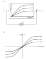
基本マップ部121は、基本マップを有し、基本マップを用いて、車速Vsをパラメータとするトルク信号(第1トルク信号)Tref_aを出力する。基本マップはチューニングにより調整されており、例えば、図6(A)に示されるように、トルク信号Tref_aは、操舵角θhの大きさ(絶対値)|θh|が増加するにつれて増加し、車速Vsが増加するにつれても増加するようになっている。なお、図6(A)において、符号部121Aは操舵角θhの符号(+1、-1)を乗算部121Bに出力しており、操舵角θhの大きさからマップによりトルク信号Tref_aの大きさを求め、これに操舵角θhの符号を乗算し、トルク信号Tref_aを求める構成となっているが、図6(B)に示されるように、正負の操舵角θhに応じてマップを構成しても良く、この場合、操舵角θhが正の場合と負の場合とで変化の態様、例えば傾き等を変えても良い。また、図6に示される基本マップは車速感応であるが、車速感応でなくても良い。
The
微分部122は、操舵角θhを微分して角速度情報である舵角速度ωhを算出し、舵角速度ωhは乗算部125に入力される。
The
ダンパゲイン部123は、舵角速度ωhに乗算されるダンパゲインDGを出力する。乗算部125にて舵角速度ωhにダンパゲインDGを乗算し、乗算結果はトルク信号(第2トルク信号)Tref_bとして加算部127に入力される。ダンパゲインDGは、ダンパゲイン部123が有する車速感応型のダンパゲインマップを用いて、車速Vsに応じて求められる。ダンパゲインマップは、例えば、図7に示されるように、車速Vsが高くなるに従って徐々に大きくなる特性を有する。ダンパゲインマップは操舵角θhに応じて可変としても良い。なお、ダンパゲイン部123及び乗算部125でダンパ演算部を構成している。
The
ヒステリシス補正部124は操舵角θh及び操舵状態STsに基づき、下記数3に従ってトルク信号(第3トルク信号)Tref_cを演算する。なお、下記数3では、x=θh、y=Tref_cとしており、a>1、c>0であり、Ahysはヒステリシス幅である。
The


“a”として1より大きい任意の正数を用いることができ、例えば、ネイピア数“e”を用いた場合、数3及び数4は下記数5及び数6となる。
Any positive number greater than 1 can be used as "a". For example, when Napier's number "e" is used,


なお、ヒステリシス特性の出力幅を表す係数であるAhys及び丸みを表す係数であるcを、車速Vs及び/又は操舵角θhに応じて可変としても良い。 Note that A hys , which is a coefficient representing the output width of the hysteresis characteristic, and c, which is a coefficient representing roundness, may be made variable depending on the vehicle speed Vs and/or the steering angle θh.
トルク信号Tref_c、Tref_b及びTref_aは、加算部127及び126で順次加算され、目標操舵トルクTrefとして出力される。
Torque signals Tref_c, Tref_b, and Tref_a are sequentially added by adding
なお、舵角速度ωhは、操舵角θhに対する微分演算により求めているが、高域のノイズの影響を低減するために適度にローパスフィルタ(LPF)処理を実施している。また、ハイパスフィルタ(HPF)とゲインにより、微分演算とLPFの処理を実施しても良い。更に、舵角速度ωhは、操舵角θhではなく、上側角度センサが検出するハンドル角θ1又は下側角度センサが検出するコラム角θ2に対して微分演算とLPFの処理を行って算出しても良い。舵角速度ωhの代わりにモータ角速度ωmを角速度情報として使用しても良く、この場合、微分部122は不要となる。
Note that the steering angular velocity ωh is obtained by differential calculation with respect to the steering angle θh, and low-pass filter (LPF) processing is appropriately performed to reduce the influence of high-frequency noise. Further, differential calculation and LPF processing may be performed using a high pass filter (HPF) and gain. Furthermore, the steering angular velocity ωh is calculated by performing differential calculation and LPF processing on the steering wheel angle θ1 detected by the upper angle sensor or the column angle θ2 detected by the lower angle sensor, instead of the steering angle θh. Also good. The motor angular velocity ωm may be used as the angular velocity information instead of the steering angular velocity ωh, and in this case, the
変換部130は、トーションバー2Aのバネ定数Ktの逆数の符号を反転した-1/Ktの特性を有しており、目標操舵トルクTrefを目標捩れ角Δθrefに変換する。
The
捩れ角制御部140は、フィードバックされるトーションバーの捩れ角に対する追従制御を行うことにより、トーションバー2Aの捩れ角Δθ及び目標捩れ角Δθrefに基づいてモータ電流指令値Imcを演算する。図9は捩れ角制御部140の構成例を示すブロック図であり、捩れ角制御部140は、入力制限部141、レート制限部142、捩れ角フィードバック(FB)補償部143、捩れ角速度演算部144、速度制御部160、出力制限部145及び減算部146を備えており、変換部130から出力される目標捩れ角Δθrefは入力制限部141に入力され、捩れ角Δθは減算部146に減算入力されると共に、捩れ角速度演算部144に入力される。
The torsion
入力制限部141は、通信やマイコン、ECUの演算等において、目標捩れ角Δθrefが異常値となった場合に、捩れ角制御部140が異常なモータ電流指令値Imcを出力しないように、目標捩れ角Δθrefの上下限値を制限する。図10に示されるように、目標捩れ角Δθrefに対する上限値及び下限値を予め設定しておき、入力した目標捩れ角Δθrefが上限値以上の場合は上限値を目標捩れ角Δθref’とし、下限値以下の場合は下限値を目標捩れ角Δθref’とし、それ以外の場合は目標捩れ角Δθrefをそのまま目標捩れ角Δθref’として出力する。設定する上限値及び下限値としては、制御上使用する捩れ角の最大値及び最小値でも良いし、検出可能な捩れ角の範囲の最大値及び最小値でも良い。これにより、安全性の確保を図る。
The
レート制限部142は、目標捩れ角Δθrefが異常値となった場合に、値が連続的に変化せず、不連続的に変動することを防止するために、目標捩れ角Δθref’の変化量に対して制限をかけ、目標捩れ角Δθref”を出力する。通常では目標捩れ角は連続的に変化し、レート制限部142による制限はかからないが、何らかの異常により一時的に目標捩れ角が異常値になった場合、レート制限部142により制限をかけることによって、不連続的な変化を防止する。例えば、1サンプル前の目標捩れ角Δθref”と現サンプルでの目標捩れ角Δθref’との差分を変化量とし、その変化量の絶対値が所定の値より大きい場合、変化量の絶対値がその所定の値となるように目標捩れ角Δθref’を加減算し、目標捩れ角Δθref”として出力し、所定の値以下の場合は、目標捩れ角Δθref’をそのまま目標捩れ角Δθref”として出力する。1サンプル前の目標捩れ角Δθref”に対する差分の割合を変化量とする等により、制限をかけても良い。
The
なお、入力制限部141とレート制限部142の配置は逆にしても良いが、図9のような配置が好ましい。また、異常値や不連続値への対応を別の手段で行なう場合等では、入力制限部141及び/又はレート制限部142は削除可能である。
Note that the arrangement of the
捩れ角FB補償部143は、減算部146で算出される目標捩れ角Δθref”と捩れ角Δθの偏差Δθ0に対して補償値CFB(伝達関数)を乗算し、目標捩れ角Δθrefに捩れ角Δθが追従するような目標捩れ角速度ωrefを出力する。補償値CFBは単純なゲインKppでも、PI制御の補償値など一般的に用いられている補償値でも良い。目標捩れ角速度ωrefは速度制御部160に入力される。捩れ角FB補償部143と速度制御部160により、目標捩れ角Δθrefに捩れ角Δθを追従させ、所望の操舵トルクを実現することが可能となる。
The torsion angle
捩れ角速度演算部144は、捩れ角Δθに対する微分演算により捩れ角速度ωtを算出し、捩れ角速度ωtは速度制御部160に入力される。微分演算として、HPFとゲインによる擬似微分を行なっても良い。また、捩れ角速度ωtを別の手段や捩れ角Δθ以外から算出し、速度制御部160に入力するようにしても良い。
The torsion angular
速度制御部160は、目標捩れ角速度ωrefに捩れ角速度ωtが追従するようなモータ電流指令値Imcaを算出する。速度制御部160は、比例部161、ゲイン部162、擬似積分部163、減算部164及び加算部165を備え、比例部161にて比例補償を行い、ゲイン部162及び擬似積分部163にて擬似積分補償を行う。減算部164は目標捩れ角速度ωrefと捩れ角速度ωtとの差分Δω(=ωref-ωt)を算出し、差分Δωは比例部161及びゲイン部162に入力される。比例部161は差分Δωに対してゲインKvpを乗算することにより比例補償を行う。ゲイン部162は差分ΔωにゲインKviを乗算し、その乗算結果に対して、擬似積分部163は擬似積分を行う。擬似積分として、例えば、下記数7のような1次遅れの形式で表現される関数を使用する。
The

出力制限部145は、速度制御部160から出力されるモータ電流指令値Imcaの上下限値を制限して、モータ電流指令値Imcを出力する。入力制限部141と同様に、モータ電流指令値Imcaに対する上限値及び下限値を予め設定して制限をかける。なお、異常値への対応を別の手段で行なう場合等では、入力制限部141の場合と同様に、出力制限部145も削除可能である。
このような構成において、本実施形態の動作例を図11~図13のフローチャートを参照して説明する。 In such a configuration, an example of the operation of this embodiment will be described with reference to flowcharts in FIGS. 11 to 13.
動作を開始すると、右切り/左切り判定部110は、モータ角速度ωmを入力し、モータ角速度ωmの符号を基に操舵が右切りか左切りかを判定し、判定結果を操舵状態STsとして、目標操舵トルク生成部120に出力する(ステップS10)。
When the operation starts, the right-turn/left-
目標操舵トルク生成部120は、操舵状態STsと共に、操舵角θh及び車速Vsを入力し、目標操舵トルクTrefを生成する(ステップS20)。目標操舵トルク生成部120の動作例については、図12のフローチャートを参照して説明する。
The target steering
目標操舵トルク生成部120に入力された操舵角θhは基本マップ部121、微分部122及びヒステリシス補正部124に、操舵状態STsはヒステリシス補正部124に、車速Vsは基本マップ部121及びダンパゲイン部123にそれぞれ入力される(ステップS21)。
The steering angle θh input to the target steering
基本マップ部121は、図6(A)又は(B)に示される基本マップを用いて、操舵角θh及び車速Vsに応じたトルク信号Tref_aを生成して、加算部126に出力する(ステップS22)。
The
微分部122は操舵角θhを微分して舵角速度ωhを出力し(ステップS23)、ダンパゲイン部123は図7に示されるダンパゲインマップを用いて車速Vsに応じたダンパゲインDGを出力し(ステップS24)、乗算部125は舵角速度ωh及びダンパゲインDGを乗算してトルク信号Tref_bを演算し、加算部127に出力する(ステップS25)。
The
ヒステリシス補正部124は、操舵角θhに対して、操舵状態STsに応じて数5及び数6による演算を切り替えてヒステリシス補正を実施し(ステップS26)、トルク信号Tref_cを生成し、加算部127に出力する(ステップS27)。なお、数5及び数6におけるヒステリシス幅Ahys、c、x1及びy1は予め設定し保持されているが、数6よりb及びb’を予め算出し、x1及びy1の代わりにb及びb’を保持するようにしても良い。
The
そして、加算部127にてトルク信号Tref_b及びTref_cが加算され、更に、その加算結果にトルク信号Tref_aが加算部126にて加算され、目標操舵トルクTrefが演算される(ステップS28)。
Then, the adding
目標操舵トルク生成部120で生成された目標操舵トルクTrefは変換部130に入力され、変換部130で目標捩れ角Δθrefに変換される(ステップS30)。目標捩れ角Δθrefは捩れ角制御部140に入力される。
The target steering torque Tref generated by the target steering
捩れ角制御部140は、目標捩れ角Δθrefと共に、捩れ角Δθを入力し、モータ電流指令値Imcを演算する(ステップS40)。捩れ角制御部140の動作例については、図13のフローチャートを参照して説明する。
The torsion
捩れ角制御部140に入力された目標捩れ角Δθrefは入力制限部141に、捩れ角Δθは捩れ角速度演算部144及び減算部146にそれぞれ入力される(ステップS41)。
The target torsion angle Δθref input to the torsion
入力制限部141は、予め設定された上限値及び下限値により目標捩れ角Δθrefの上下限値を制限し、目標捩れ角Δθref’としてレート制限部142に出力し(ステップS42)、レート制限部142は、目標捩れ角Δθref’の変化量に対して制限をかけて、目標捩れ角Δθref”として減算部146に出力する(ステップS43)。
The
減算部146では、目標捩れ角Δθref”から捩れ角Δθを減算することにより、偏差Δθ0が算出される(ステップS44)。偏差Δθ0は捩れ角FB補償部143に入力され、捩れ角FB補償部143は、偏差Δθ0に補償値CFBを乗算することにより偏差Δθ0を補償し(ステップS45)、目標捩れ角速度ωrefとして速度制御部160に出力する。
The
捩れ角Δθを入力した捩れ角速度演算部144は、捩れ角Δθに対する微分演算により捩れ角速度ωtを算出し(ステップS46)、速度制御部160に出力する。
The torsion angular
速度制御部160では、目標捩れ角速度ωrefと捩れ角速度ωtの差分Δωが減算部164で算出され、差分Δωは比例部161及びゲイン部162に入力される(ステップS47)。比例部161は、ゲインKvpの乗算により差分Δωに対して比例補償を行い、加算部165に出力する(ステップS48)。ゲイン部162に入力された差分Δωに対しては、ゲイン部162でのゲインKviの乗算及び擬似積分部163での数7を用いた擬似積分補償が行われ、加算部165に出力される(ステップS49)。加算部165では、比例部161からの出力と擬似積分部163からの出力が加算され、モータ電流指令値Imcaとして出力制限部145に出力される(ステップS50)。
In the
出力制限部145は、予め設定された上限値及び下限値によりモータ電流指令値Imcaの上下限値を制限し(ステップS51)、モータ電流指令値Imcとして出力する(ステップS52)。
The
捩れ角制御部140から出力されたモータ電流指令値Imcに基づいてモータを駆動し、電流制御が実施される(ステップS60)。
The motor is driven based on the motor current command value Imc output from the twist
なお、図11~図13におけるデータ入力及び演算等の順番は適宜変更可能である。 Note that the order of data input, calculation, etc. in FIGS. 11 to 13 can be changed as appropriate.
本実施形態による目標操舵トルクへの追従性の効果について、速度制御部にて比例補償のみを行った場合との比較により、シミュレーション結果を基に説明する。 The effect of followability to the target steering torque according to this embodiment will be explained based on simulation results in comparison with a case where only proportional compensation is performed in the speed control section.
シミュレーションでは、ハンドルを操舵している状況を想定し、図14に示されるように、操舵角θhを、約30degの振幅で、約1.0Hzの周波数で正弦波状に変化させ、その場合の目標操舵トルクTref及び操舵トルクTsの変化の様子を調べた。なお、図14において、横軸は時間[sec]、縦軸は操舵角[deg]である。 In the simulation, assuming a situation where the steering wheel is being steered, the steering angle θh is changed sinusoidally with an amplitude of about 30 degrees and a frequency of about 1.0 Hz, as shown in FIG. 14, and the target in that case is The changes in the steering torque Tref and the steering torque Ts were investigated. In addition, in FIG. 14, the horizontal axis is time [sec], and the vertical axis is steering angle [deg].
シミュレーション結果を図15に示す。図15において、横軸は時間[sec]、縦軸は操舵トルク[Nm]であり、目標操舵トルクを太線で、速度制御部で比例補償のみを行った場合の操舵トルクを細線で、速度制御部で比例補償及び擬似積分補償を行う本実施形態の場合の操舵トルクを破線で示している。図15より、速度制御部で比例補償のみを行った場合でも、全域において、操舵トルクは目標操舵トルクに比較的良く追従しているが、誤差が残っていることがわかる。これに対して、本実施形態の場合は、定常誤差が低減し、目標操舵トルクに、より良く追従していることがわかる。 The simulation results are shown in FIG. In FIG. 15, the horizontal axis is time [sec] and the vertical axis is steering torque [Nm]. The thick line represents the target steering torque, and the thin line represents the steering torque when only proportional compensation is performed in the speed control section. The dashed line indicates the steering torque in this embodiment in which proportional compensation and pseudo-integral compensation are performed in this embodiment. From FIG. 15, it can be seen that even when only proportional compensation is performed in the speed control section, the steering torque follows the target steering torque relatively well over the entire range, but errors remain. On the other hand, in the case of the present embodiment, it can be seen that the steady-state error is reduced and the target steering torque is tracked better.
本発明の他の構成例について説明する。 Another configuration example of the present invention will be explained.
図9に示される第1実施形態での捩れ角制御部140内の速度制御部160では、比例補償を行う比例部161と擬似積分補償を行うゲイン部162及び擬似積分部163が並列に配置されているが、この2つの補償を合算して、等価的にゲインと位相遅れフィルタで2つの補償を表わすことができる。この場合の捩れ角制御部の構成例(第2実施形態)を図16に示す。この構成でも、第1実施形態と同様の制御性能を実現することができる。
In the
図16に示される第2実施形態での捩れ角制御部では、速度制御部260の構成のみが第1実施形態と異なり、他の構成は同じである。速度制御部260はゲイン部261、位相遅れフィルタ部262及び減算部164を備え、速度制御部160と同様に、目標捩れ角速度ωref及び捩れ角速度ωtを入力し、目標捩れ角速度ωrefに捩れ角速度ωtが追従するようなモータ電流指令値Imcaを算出する。ゲイン部261は、減算部164で算出される目標捩れ角速度ωrefと捩れ角速度ωtとの差分Δωに対してゲインKvを乗算する。位相遅れフィルタ部は、位相遅れフィルタを有しており、ゲイン部261からの出力に対して位相遅れフィルタによるフィルタ処理を行い、モータ電流指令値Imcaを算出する。
The torsion angle control section according to the second embodiment shown in FIG. 16 differs from the first embodiment only in the configuration of a
第2実施形態の動作例は、速度制御部での動作が上記のように第1実施形態の動作例と異なるのみで、他の動作は同じである。 The operation example of the second embodiment differs from the operation example of the first embodiment only in the operation of the speed control section as described above, and the other operations are the same.
捩れ角制御部については、速度制御部を設けずに、比例補償、擬似積分補償及び微分補償の3つの補償を行う形で構成することもできる。例えば、図17に示される構成例(第3実施形態)のように、微分先行型PID(比例積分微分)制御(PI-D制御)の構成を採用し、この構成により、第1実施形態と略同等の目標値追従性を実現することができる。なお、捩れ角制御部の構成は、PI-D制御の構成に限られず、比例補償、擬似積分補償及び微分補償を行う構成であれば、比例微分先行型PID制御等の構成でも良い。 The torsion angle control section may be configured to perform three types of compensation: proportional compensation, pseudo-integral compensation, and differential compensation, without providing the speed control section. For example, as in the configuration example (third embodiment) shown in FIG. 17, a configuration of differential-first type PID (proportional-integral-derivative) control (PI-D control) is adopted, and with this configuration, the configuration is different from that of the first embodiment. Substantially equivalent target value followability can be achieved. Note that the configuration of the torsion angle control section is not limited to the configuration of PI-D control, but may be a configuration such as proportional differential prior type PID control as long as it performs proportional compensation, pseudo-integral compensation, and differential compensation.
図17に示される第3実施形態での捩れ角制御部は、目標捩れ角及び捩れ角に基づいて、PI-D制御によりモータ電流指令値を算出する。そのために、図9に示される第1実施形態での捩れ角制御部の構成例と比べると、捩れ角FB補償部143、捩れ角速度演算部144、並びに速度制御部160内の比例部161、ゲイン部162、擬似積分部163、減算部164及び加算部165の代わりに、比例部351、ゲイン部352及び355、擬似積分部353、微分部354、加算部356並びに減算部357を備える。比例部351にて比例補償を行い、ゲイン部352及び擬似積分部353にて擬似積分補償を行い、微分部354及びゲイン部355にて微分補償を行う。
The torsion angle control unit in the third embodiment shown in FIG. 17 calculates a motor current command value by PI-D control based on the target torsion angle and the torsion angle. Therefore, compared to the configuration example of the torsion angle control section in the first embodiment shown in FIG. In place of the
減算部146にて算出される目標捩れ角Δθref”と捩れ角Δθの偏差Δθ0は比例部351及びゲイン部352に入力され、捩れ角Δθは捩れ角速度演算部144でなく微分部354に入力される。比例部351は、偏差Δθ0に対してゲインKpを乗算することにより比例補償を行う。ゲイン部352は、偏差Δθ0にゲインKiを乗算し、その乗算結果に対して、擬似積分部353は擬似積分を行う。擬似積分では、擬似積分部163と同様の1次遅れの形式で表現される関数を使用しても良いし、他の形式の関数を使用しても良い。微分部354は、捩れ角Δθを微分し、その微分結果に対して、ゲイン部355にてゲインKdを乗算する。比例部351の出力と擬似積分部353の出力は加算部356にて加算され、その加算結果からゲイン部355の出力を減算部357にて減算し、減算結果がモータ電流指令値Imcaとして出力される。
The deviation Δθ 0 between the target torsion angle Δθref and the torsion angle Δθ calculated by the
第3実施形態の動作例は、第1実施形態の動作例と比べると、捩れ角制御部の動作が異なり、他は同じである。第3実施形態での捩れ角制御部の動作例を図18に示す。 The operation example of the third embodiment is different from the operation example of the first embodiment except for the operation of the torsion angle control section, and is otherwise the same. FIG. 18 shows an example of the operation of the twist angle control section in the third embodiment.
目標捩れ角Δθrefは入力制限部141に、捩れ角Δθは微分部354及び減算部146にそれぞれ入力される(ステップS41A)。
The target torsion angle Δθref is input to the
入力制限部141及びレート制限部142は、第1実施形態の場合と同様の動作により目標捩れ角に対する制限処理を行い、目標捩れ角Δθref”が減算部146に加算入力され、減算部146にて偏差Δθ0が算出される(ステップS42~S44)。偏差Δθ0は比例部351及びゲイン部352に入力される。
The
比例部351は、ゲインKpの乗算により偏差Δθ0に対して比例補償を行い、加算部356に出力する(ステップS48A)。ゲイン部352に入力された偏差Δθ0に対しては、ゲイン部352でのゲインKiの乗算及び擬似積分部353での擬似積分により擬似積分補償が行われ、加算部356に出力される(ステップS49A)。加算部356では、比例部351からの出力と擬似積分部353からの出力が加算される(ステップS50A)。
The
微分部354に入力された捩れ角Δθに対しては、微分部354での微分演算及びゲイン部355でのゲインKpの乗算により微分補償が行われ、減算部357に出力される(ステップS50B)。そして、減算部357にて、加算部356から出力された加算結果からゲイン部355の出力を減算することによりモータ電流指令値Imcaが算出され(ステップS50C)、出力制限部145に出力される。
Differential compensation is performed on the torsion angle Δθ inputted to the
出力制限部145は、第1実施形態の場合と同様の動作により、モータ電流指令値Imcaの上下限値を制限し(ステップS51)、モータ電流指令値Imcとして出力する(ステップS52)。
The
なお、図18におけるデータ入力及び演算等の順番は適宜変更可能である。 Note that the order of data input, calculation, etc. in FIG. 18 can be changed as appropriate.
第1及び第3実施形態での捩れ角制御部における擬似積分補償の割合を運転状況に応じて変更させるようにしても良い。擬似積分補償の割合を変更することにより、運転者の手感に対して、路面から伝わるSAT感(路面反力感)を適宜変更することができる。SAT感等の路面情報に関しては、路面状況を把握するために積極的に伝える、抵抗感を小さくするために抑えて伝える等、操舵感としてどの程度を運転者に伝えるかは、運転状況や運転者の好みに依存するところがある。よって、その伝える量を調整できるようにする。 The ratio of pseudo-integral compensation in the torsion angle control section in the first and third embodiments may be changed depending on the driving situation. By changing the ratio of pseudo-integral compensation, the SAT feeling (road surface reaction force feeling) transmitted from the road surface can be changed as appropriate with respect to the driver's hand feeling. Regarding road surface information such as SAT feeling, the amount of steering feeling to be communicated to the driver depends on the driving situation and driving, such as actively communicating it to understand the road surface condition, or suppressing it to reduce the feeling of resistance. It depends on the person's preference. Therefore, the amount of information to be transmitted can be adjusted.
上記の擬似積分補償の割合を変更する機能(以下、「補償変更機能」とする)を第3実施形態での捩れ角制御部に追加した場合の構成例(第4実施形態)を図19に示す。第4実施形態での捩れ角制御部では、目標捩れ角Δθref”と捩れ角Δθの偏差Δθ0に、積分ゲインであるゲインKiを乗算する前に補償変更フラグCfを乗算することにより、擬似積分補償の割合を変更する。図17に示される第3実施形態での捩れ角制御部の構成例と比べると、第4実施形態での捩れ角制御部では補償変更フラグ設定部471及び乗算部472が追加されており、減算部146から出力される偏差Δθ0に補償変更フラグ設定部471から出力される補償変更フラグCfを乗算部472にて乗算し、その乗算結果がゲイン部352に入力される。
FIG. 19 shows a configuration example (fourth embodiment) in which the function of changing the ratio of pseudo-integral compensation described above (hereinafter referred to as "compensation change function") is added to the torsion angle control section in the third embodiment. show. In the torsion angle control section in the fourth embodiment, the deviation Δθ 0 between the target torsion angle Δθref and the torsion angle Δθ is multiplied by the compensation change flag Cf before being multiplied by the gain Ki, which is an integral gain, so that the pseudo-integral Change the compensation ratio.Compared with the configuration example of the torsion angle control unit in the third embodiment shown in FIG. is added, the deviation Δθ 0 output from the
補償変更フラグ設定部471では、補償変更フラグCfに所望の値を設定する。例えば、図20に示されるようなレベルメーターを設け、運転者がレベルメーターにてレベルを変えることにより、路面からのSAT感を調整できるようにする。図20において、「HIGH」はSAT感が強くなり、「LOW」はSAT感が弱くなることを示しており、「HIGH」では補償変更フラグCfに0に近い値(最小で0)を設定し、「LOW」では大きな値を設定する。運転者は、SAT感を変えたい場合、レベルメーターのレベルを所望のレベルに設定し、「SET」ボタンを押下する。「SET」ボタンの押下により、設定されたレベルに対応して補償変更フラグCfに値が設定され、SAT感が変わる。「SET」ボタンではなく、「CANCEL」ボタンを押下した場合は、設定したレベルはキャンセルされ、元のレベルに戻る。なお、「SET」ボタン及び「CANCEL」ボタンをなくし、レベルを設定した時点で補償変更フラグCfの値を変更し、SAT感を変えるようにしても良い。
The compensation change
第4実施形態の動作例は、第3実施形態の動作例と比べると、捩れ角制御部の動作が異なり、他は同じである。第4実施形態での捩れ角制御部の動作例を図21に示す。 The operation example of the fourth embodiment is different from the operation example of the third embodiment except for the operation of the torsion angle control section, and is otherwise the same. FIG. 21 shows an example of the operation of the twist angle control section in the fourth embodiment.
第4実施形態では、比例補償(ステップS48A)までは第3実施形態と同じ動作を行い、減算部146にて算出された偏差Δθ0はゲイン部352ではなく、乗算部472に入力される。乗算部472では、補償変更フラグ設定部471で設定された補償変更フラグCfが偏差Δθ0に乗算され、乗算結果がゲイン部352に入力される(ステップS48B)。それ以降の動作は第3実施形態と同じである(ステップS49A~)。なお、図18の場合と同様に、図21におけるデータ入力及び演算等の順番も適宜変更可能である。
In the fourth embodiment, the same operation as in the third embodiment is performed up to proportional compensation (step S48A), and the deviation Δθ 0 calculated by the
第4実施形態では運転者の設定により補償変更フラグCfの値を変更し、SAT感を変更しているが、操舵トルク等の運転状況を示す変数に連動して補償変更フラグCfの値を変更するようにしても良い。変数に対する補償変更フラグCfの特性を予め定義することにより、自動的にSAT感を変更できるようになる。 In the fourth embodiment, the value of the compensation change flag Cf is changed according to the driver's settings to change the SAT feeling, but the value of the compensation change flag Cf is changed in conjunction with variables indicating driving conditions such as steering torque. You may also do this. By predefining the characteristics of the compensation change flag Cf for variables, it becomes possible to automatically change the SAT feeling.
第4実施形態では、補償変更フラグCfを乗算する乗算部472を、ゲイン部352の前段に設けているが、擬似積分補償の割合を変更できれば良いので、ゲイン部352の後段又は擬似積分部353の後段に設けても良い。
In the fourth embodiment, the
また、第4実施形態では第3実施形態での捩れ角制御部に補償変更機能を追加しているが、第1実施形態での捩れ角制御部に補償変更機能を追加することも可能である。第1実施形態での捩れ角制御部に補償変更機能を追加する場合は、速度制御部160内のゲイン部162の前段に補償変更フラグCfを乗算する乗算部を設け、目標捩れ角速度ωrefと捩れ角速度ωtとの差分Δωに補償変更フラグCfを乗算し、その乗算結果をゲイン部162に入力することになる。乗算部をゲイン部162の後段又は擬似積分部163の後段に設けても良い。
Further, in the fourth embodiment, a compensation change function is added to the torsion angle control section in the third embodiment, but it is also possible to add a compensation change function to the torsion angle control section in the first embodiment. . When adding a compensation change function to the torsion angle control section in the first embodiment, a multiplication section that multiplies the compensation change flag Cf is provided before the
ここで、路面からの反力が発生した場合の擬似積分補償による効果とそれによる操舵感への影響について、シミュレーション結果を基に説明する。 Here, the effect of pseudo-integral compensation when a reaction force from the road surface occurs and its influence on the steering feel will be explained based on simulation results.
シミュレーションでは、路面からの反力を簡易的に模擬するために、インターミディエイトシャフトに、図22(A)に示されるような、片振幅が5Nmで、周波数が0.1Hzから2Hzへと徐々に変化するスイープ信号のトルク(以下、「インタミシャフトトルク」とする)をかけ、擬似積分補償がある場合とない場合の操舵トルク(トーションバートルク)の変化の様子を調べた。また、操舵角を0degで保持した状態で固定とするために、目標操舵トルクは0Nmで固定とした。擬似積分補償は、遮断周波数が1Hzの1次遅れとゲインを用いて行った。 In the simulation, in order to simply simulate the reaction force from the road surface, the intermediate shaft was gradually increased in frequency from 0.1 Hz to 2 Hz, with a single amplitude of 5 Nm, as shown in Fig. 22(A). We applied a varying sweep signal torque (hereinafter referred to as "intermediate shaft torque") to examine how the steering torque (torsion bar torque) changes with and without pseudo-integral compensation. Further, in order to keep the steering angle fixed at 0 degrees, the target steering torque was fixed at 0 Nm. Pseudo-integral compensation was performed using a first-order delay with a cutoff frequency of 1 Hz and a gain.
シミュレーション結果を図22(B)に示す。図22(B)において、横軸は時間[sec]、縦軸は操舵トルク[Nm]であり、擬似積分補償がある場合の操舵トルクを太線で、擬似積分補償がない場合の操舵トルクを破線で示している。目標操舵トルクを細線で示しているが、本シミュレーションでは目標操舵トルクは0Nmで固定としたので、横軸と重なっている。また、比較のために、擬似積分補償の代わりに純積分による補償を行った場合の操舵トルクを一点鎖線で示す。図22(B)を見ると、破線で示される波形の振幅が他より大きくなっており、擬似積分補償がない場合、インタミシャフトトルクの影響が操舵トルクに反映されやすい(操舵トルクに出やすい)ことがわかる。それに対して、太線で示される波形の振幅は小さくなっており、擬似積分補償がある場合、擬似積分補償がない場合に比べて、操舵トルクに対するインタミシャフトトルクの影響が低減されていることがわかる。また、インタミシャフトトルクの影響は、インタミシャフトトルクの周波数が小さい程、低減されており、路面反力の情報が運転者に操舵感として適度に伝えられていることがわかる。純積分による補償の場合は、インタミシャフトトルクの周波数が小さい程、操舵トルクが0Nmに近くなっており、路面反力の情報が運転者に操舵感として伝わりにくくなっており、このことが逆に違和感として感じられるおそれがある。 The simulation results are shown in FIG. 22(B). In FIG. 22(B), the horizontal axis is time [sec] and the vertical axis is steering torque [Nm]. The thick line indicates the steering torque with pseudo-integral compensation, and the broken line indicates the steering torque without pseudo-integral compensation. It is shown in The target steering torque is shown by a thin line, but in this simulation, the target steering torque was fixed at 0 Nm, so it overlaps with the horizontal axis. For comparison, the steering torque when pure integral compensation is performed instead of pseudo-integral compensation is shown by a dashed-dotted line. Looking at FIG. 22(B), the amplitude of the waveform indicated by the broken line is larger than the others, and if there is no pseudo-integral compensation, the influence of the intermediate shaft torque is likely to be reflected in the steering torque (easily reflected in the steering torque). I understand that. On the other hand, the amplitude of the waveform indicated by the thick line is smaller, indicating that the influence of intermittent shaft torque on steering torque is reduced when there is pseudo-integral compensation compared to when there is no pseudo-integral compensation. . Furthermore, the influence of the intermittent shaft torque is reduced as the frequency of the intermittent shaft torque becomes smaller, and it can be seen that information on the road reaction force is appropriately conveyed to the driver as a steering feeling. In the case of compensation using pure integrals, the smaller the frequency of the intermittent shaft torque, the closer the steering torque is to 0Nm, making it difficult for information on road reaction force to be transmitted to the driver as a steering feeling. There is a possibility that it may be felt as a sense of discomfort.
図20に示されるようなレベルメーターを使用した場合、レベルを「HIGH」に近づけると、本シミュレーションでの破線(擬似積分補償がない場合)の設定に近づき、路面反力の情報が運転者に操舵感として伝わり易くなる。レベルを「LOW」に近づけると、本シミュレーションでの太線(擬似積分補償がある場合)の設定となっていき、路面反力の情報が運転者に操舵感として伝わりにくくなる。 When using a level meter as shown in Figure 20, as the level approaches "HIGH", it approaches the setting of the broken line in this simulation (in the case of no pseudo-integral compensation), and road reaction force information becomes available to the driver. This becomes easier to convey as a steering feeling. When the level approaches "LOW", the setting becomes a thick line in this simulation (when there is pseudo-integral compensation), and it becomes difficult for information on road reaction force to be transmitted to the driver as a steering feeling.
第1~第4実施形態での捩れ角制御部から出力されるモータ電流指令値Imcに、従来のEPSにおいて操舵トルクに基づいて演算される電流指令値(以下、「アシスト電流指令値」とする)を、例えば、図2に示される電流指令値演算部31から出力される電流指令値Iref1又は電流指令値Iref1に補償信号CMを加算した電流指令値Iref2等を加算しても良い。
The motor current command value Imc output from the torsion angle control unit in the first to fourth embodiments is combined with the current command value (hereinafter referred to as "assist current command value") calculated based on the steering torque in the conventional EPS. ) may be added, for example, to the current command value Iref1 output from the current command
第1実施形態に対して、上記の内容を適用した構成例(第5実施形態)を図23に示す。アシスト制御部500は、電流指令値演算部31、又は、電流指令値演算部31、補償信号生成部34及び加算部32Aから構成される。アシスト制御部500から出力されるアシスト電流指令値Iac(図2における電流指令値Iref1又はIref2に相当)と、捩れ角制御部140から出力されるモータ電流指令値Imcは、加算部580で加算され、加算結果である電流指令値Icは電流制限部590に入力され、最大電流を制限された電流指令値Icmに基づいてモータを駆動し、電流制御が実施される。
FIG. 23 shows a configuration example (fifth embodiment) in which the above content is applied to the first embodiment. The
第1~第5実施形態での目標操舵トルク生成部120において、コストや処理時間を重視する場合等では、基本マップ部121、ダンパ演算部及びヒステリシス補正部124の内の少なくとも1つを残して、他を省略しても良い。基本マップ部121を省略する場合、加算部126も省略可能で、ダンパ演算部を省略する場合、微分部122及び加算部127も省略可能で、ヒステリシス補正部124を省略する場合、右切り/左切り判定部110及び加算部127も省略可能である。また、基本マップ部121の前段又は後段に位相補償を行なう位相補償部128を挿入しても良い。つまり、図5中の破線で囲まれた領域Rの構成を、図24(A)又は(B)に示されるような構成にしても良い。位相補償部128において、位相補償として位相進み補償を設定し、例えば、分子のカットオフ周波数を1.0Hz、分母のカットオフ周波数を1.3Hzとした1次フィルタで位相進み補償を行う場合、スッキリしたフィールを実現することができる。目標操舵トルク生成部に関しては、操舵角に基づいた構成であるならば、上述の構成に限られない。
In the target steering
図1及び図3では本発明をコラム型EPSに適用しているが、本発明はコラム型等の上流型に限られず、ラック&ピニオン等の下流型EPSにも適用可能である。更に、目標捩れ角に基づくフィードバック制御を行うということでは、トーションバー(バネ定数任意)及び捩れ角検出用のセンサを少なくとも備えるステアバイワイヤ(SBW)反力装置等にも適用可能である。本発明を、トーションバーを備えたSBW反力装置に適用した場合の実施形態(第6実施形態)について説明する。 Although the present invention is applied to a column-type EPS in FIGS. 1 and 3, the present invention is not limited to upstream-type EPS such as column-type, but can also be applied to downstream-type EPS such as rack and pinion. Furthermore, by performing feedback control based on the target torsion angle, it is also applicable to a steer-by-wire (SBW) reaction force device, etc., which includes at least a torsion bar (with an arbitrary spring constant) and a sensor for detecting the torsion angle. An embodiment (sixth embodiment) in which the present invention is applied to an SBW reaction force device including a torsion bar will be described.
まずは、SBW反力装置を含むSBWシステム全体について説明する。図25はSBWシステムの構成例を、図1に示される電動パワーステアリング装置の一般的な構成に対応させて示した図である。なお、同一構成には同一符号を付し、詳細な説明は省略する。 First, the entire SBW system including the SBW reaction device will be explained. FIG. 25 is a diagram showing an example of the configuration of the SBW system in correspondence with the general configuration of the electric power steering device shown in FIG. 1. In FIG. Note that the same configurations are denoted by the same reference numerals, and detailed explanations will be omitted.
SBWシステムは、ユニバーサルジョイント4aにてコラム軸2と機械的に結合されるインターミディエイトシャフトがなく、ハンドル1の操作を電気信号によって操向車輪8L,8R等からなる転舵機構に伝えるシステムである。図25に示されるように、SBWシステムは反力装置60及び駆動装置70を備え、コントロールユニット(ECU)50が両装置の制御を行う。反力装置60は、舵角センサ14にて操舵角θhの検出を行うと同時に、操向車輪8L,8Rから伝わる車両の運動状態を反力トルクとして運転者に伝達する。反力トルクは、反力用モータ61により生成される。なお、SBWシステムの中には反力装置内にトーションバーを有さないタイプもあるが、本発明を適用するSBWシステムはトーションバーを有するタイプであり、トルクセンサ10にて操舵トルクTsを検出する。また、角度センサ74が、反力用モータ61のモータ角θmを検出する。駆動装置70は、運転者によるハンドル1の操舵に合わせて、駆動用モータ71を駆動し、その駆動力を、ギア72を介してピニオンラック機構5に付与し、タイロッド6a,6bを経て、操向車輪8L,8Rを転舵する。ピニオンラック機構5の近傍には角度センサ73が配置されており、操向車輪8L,8Rの転舵角θtを検出する。ECU50は、反力装置60及び駆動装置70を協調制御するために、両装置から出力される操舵角θhや転舵角θt等の情報に加え、車速センサ12からの車速Vs等を基に、反力用モータ61を駆動制御する電圧制御指令値Vref1及び駆動用モータ71を駆動制御する電圧制御指令値Vref2を生成する。
The SBW system does not have an intermediate shaft that is mechanically connected to the
このようなSBWシステムに本発明を適用した第6実施形態の構成について説明する。 The configuration of a sixth embodiment in which the present invention is applied to such an SBW system will be described.
図26は第6実施形態の構成を示すブロック図である。第6実施形態は、捩れ角Δθに対する制御(以下、「捩れ角制御」とする)と、転舵角θtに対する制御(以下、「転舵角制御」とする)を行い、反力装置を捩れ角制御で制御し、駆動装置を転舵角制御で制御する。なお、駆動装置は他の制御方法で制御しても良い。 FIG. 26 is a block diagram showing the configuration of the sixth embodiment. The sixth embodiment controls the torsion angle Δθ (hereinafter referred to as "torsion angle control") and controls the steering angle θt (hereinafter referred to as "steering angle control"), and twists the reaction force device. It is controlled by angle control, and the drive device is controlled by steering angle control. Note that the drive device may be controlled using other control methods.
捩れ角制御では、第1実施形態と同様の構成及び動作により、捩れ角Δθが、操舵角θh等を用いて目標操舵トルク生成部120及び変換部130を経て算出される目標捩れ角Δθrefに追従するような制御を行う。モータ角θmは角度センサ74で検出され、モータ角速度ωmは、角速度演算部951にてモータ角θmを微分することにより算出される。転舵角θtは角度センサ73で検出される。また、第1実施形態ではEPS操舵系/車両系100内の処理として詳細な説明は行われていないが、電流制御部180は、図2に示される減算部32B、PI制御部35、PWM制御部36及びインバータ37と同様の構成及び動作により、捩れ角制御部140から出力されるモータ電流指令値Imc及びモータ電流検出器190で検出される反力用モータ61の電流値Imrに基づいて、反力用モータ61を駆動して、電流制御を行う。
In the torsion angle control, the torsion angle Δθ follows the target torsion angle Δθref calculated via the target steering
転舵角制御では、目標転舵角生成部910にて操舵角θhに基づいて目標転舵角θtrefが生成され、目標転舵角θtrefは転舵角θtと共に転舵角制御部920に入力され、転舵角制御部920にて、転舵角θtが目標転舵角θtrefとなるようなモータ電流指令値Imctが演算される。そして、モータ電流指令値Imct及びモータ電流検出器940で検出される駆動用モータ71の電流値Imdに基づいて、電流制御部930が、電流制御部160と同様の構成及び動作により、駆動用モータ71を駆動して、電流制御を行う。
In the turning angle control, a target turning angle θtref is generated based on the steering angle θh in a target turning
目標転舵角生成部910の構成例を図27に示す。目標転舵角生成部910は、制限部931、レート制限部932及び補正部933を備える。
FIG. 27 shows a configuration example of the target turning
制限部931は、操舵角θhの上下限値を制限して、操舵角θh1を出力する。捩れ角制御部内の入力制限部141及び出力制限部145と同様に、操舵角θhに対する上限値及び下限値を予め設定して制限をかける。
The limiting
レート制限部932は、操舵角の急変を回避するために、操舵角θh1の変化量に対して制限値を設定して制限をかけ、操舵角θh2を出力する。例えば、1サンプル前の操舵角θh2と現サンプルでの操舵角θh1との差分を変化量とし、その変化量の絶対値が所定の値(制限値)より大きい場合、変化量の絶対値が制限値となるように、操舵角θh1を加減算し、操舵角θh2として出力し、制限値以下の場合は、操舵角θh1をそのまま操舵角θh2として出力する。なお、変化量の絶対値に対して制限値を設定するのではなく、変化量に対して上限値及び下限値を設定して制限をかけるようにしても良く、変化量ではなく変化率や差分率に対して制限をかけるようにしても良い。
In order to avoid sudden changes in the steering angle, the
補正部933は、操舵角θh2を補正して、目標転舵角θtrefを出力する。例えば、目標操舵トルク生成部120内の基本マップ部121のように、操舵角θh2の大きさ|θh2|に対する目標転舵角θtrefの特性を定義したマップを用いて、操舵角θh2より目標転舵角θtrefを求める。或いは、単純に、操舵角θh2に所定のゲインを乗算することにより、目標転舵角θtrefを求めるようにしても良い。
The
転舵角制御部920の構成例を図28に示す。転舵角制御部920は、転舵角フィードバック(FB)補償部921、転舵角速度演算部922、速度制御部923、出力制限部926及び減算部927を備え、目標転舵角θtref及び転舵角θtに基づいてモータ電流指令値Imctを演算する。
A configuration example of the steering
転舵角FB補償部921は、減算部927で算出される目標転舵角θtrefと転舵角θtの偏差Δθt0に対して、捩れ角制御部140内の捩れ角FB補償部143と同様の動作により、目標転舵角θtrefに転舵角θtが追従するような目標転舵角速度ωtrefを算出する。目標転舵角速度ωtrefは速度制御部923に入力される。
The steering angle FB compensator 921 performs a calculation similar to the torsion angle FB compensator 143 in the
転舵角速度演算部922は、捩れ角制御部140内の捩れ角速度演算部144と同様の動作により、転舵角θtから転舵角速度ωttを算出する。転舵角速度ωttは速度制御部923に入力される。
The steering angular
速度制御部923は、I-P制御(比例先行型PI制御)により、目標転舵角速度ωtrefに転舵角速度ωttが追従するようなモータ電流指令値Imctaを算出する。減算部928で目標転舵角速度ωtrefと転舵角速度ωttとの差分(ωtref-ωtt)を算出し、その差分を、ゲインKtiを有する積分部924にて積分し、積分結果は減算部929に加算入力される。転舵角速度ωttは比例部925にも入力され、ゲインKtpによる比例処理を施され、減算部929に減算入力される。減算部929での減算結果がモータ電流指令値Imctaとして出力される。
The
出力制限部926は、モータ電流指令値Imctaの上下限値を制限して、モータ電流指令値Imctを出力する。捩れ角制御部内の入力制限部141及び出力制限部145と同様に、モータ電流指令値Imctaに対する上限値及び下限値を予め設定して制限をかける。
このような構成において、第6実施形態の動作例を図29のフローチャートを参照して説明する。 In such a configuration, an example of the operation of the sixth embodiment will be described with reference to the flowchart of FIG. 29.
動作を開始すると、角度センサ73は転舵角θtを検出し、角度センサ74はモータ角θmを検出し(ステップS110)、転舵角θtは転舵角制御部920に、モータ角θmは角速度演算部951にそれぞれ入力される。
When the operation starts, the
角速度演算部951は、モータ角θmを微分してモータ角速度ωmを算出し、右切り/左切り判定部110に出力する(ステップS120)。
The angular
その後、目標操舵トルク生成部120において、図11に示されるステップS10~S60と同様の動作を実行し、反力用モータ61を駆動し、電流制御を実施する(ステップS130~S170)。
Thereafter, the target steering
一方、転舵角制御においては、目標転舵角生成部910が操舵角θhを入力し、操舵角θhは制限部931に入力される。制限部931は、予め設定された上限値及び下限値により操舵角θhの上下限値を制限し(ステップS180)、操舵角θh1としてレート制限部932に出力する。レート制限部932は、予め設定された制限値により操舵角θh1の変化量に対して制限をかけ(ステップS190)、操舵角θh2として補正部933に出力する。補正部933は、操舵角θh2を補正して目標転舵角θtrefを求め(ステップS200)、転舵角制御部920に出力する。
On the other hand, in the steering angle control, the target steering
転舵角θt及び目標転舵角θtrefを入力した転舵角制御部920は、減算部927にて目標転舵角θtrefから転舵角θtを減算することにより、偏差Δθt0を算出する(ステップS210)。偏差Δθt0は転舵角FB補償部921に入力され、転舵角FB補償部921は、偏差Δθt0に補償値を乗算することにより偏差Δθt0を補償し(ステップS220)、目標転舵角速度ωtrefを速度制御部923に出力する。転舵角速度演算部922は転舵角θtを入力し、転舵角θtに対する微分演算により転舵角速度ωttを算出し(ステップS230)、速度制御部923に出力する。速度制御部923は、I-P制御によりモータ電流指令値Imctaを算出し(ステップS240)、出力制限部926に出力する。出力制限部926は、予め設定された上限値及び下限値によりモータ電流指令値Imctaの上下限値を制限し(ステップS250)、モータ電流指令値Imctとして出力する(ステップS260)。
The steering
モータ電流指令値Imctは電流制御部930に入力され、電流制御部930は、モータ電流指令値Imct及びモータ電流検出器940で検出された駆動用モータ71の電流値Imdに基づいて、駆動用モータ71を駆動し、電流制御を実施する(ステップS270)。
The motor current command value Imct is input to the
なお、図29におけるデータ入力及び演算等の順番は適宜変更可能である。また、転舵角制御部920内の速度制御部923は、I-P制御ではなく、PI制御、P(比例)制御、PID制御、PI-D制御等、実現可能で、P、I及びDのいずれかの制御を用いていれば良く、更に、転舵角制御部920での追従制御は、一般的に用いられている制御構造で行っても良い。転舵角制御部920については、目標角度(ここでは目標転舵角θtref)に対して実角度(ここでは転舵角θt)が追従する制御構成であれば、車両用装置に用いられている制御構成に限定されず、例えば、産業用位置決め装置や産業用ロボット等に用いられている制御構成を適用しても良い。
Note that the order of data input, calculation, etc. in FIG. 29 can be changed as appropriate. In addition, the
第6実施形態では、図25に示されるように、1つのECU50で反力装置60及び駆動装置70の制御を行っているが、反力装置60用のECUと駆動装置70用のECUをそれぞれ設けても良い。この場合、ECU同士は通信によりデータの送受信を行うことになる。また、図25に示されるSBWシステムは反力装置60と駆動装置70の間には機械的な結合を持たないが、システムに異常が発生した場合に、コラム軸2と転舵機構をクラッチ等で機械的に結合する機械的トルク伝達機構を備えるSBWシステムにも、本発明は適用可能である。このようなSBWシステムでは、システム正常時はクラッチをオフにして機械的トルク伝達を開放状態とし、システム異常時はクラッチをオンにして機械的トルク伝達を可能状態とする。
In the sixth embodiment, as shown in FIG. 25, one
上述の第1~第6実施形態での捩れ角制御部及び第5実施形態でのアシスト制御部500は、直接的にモータ電流指令値Imc及びアシスト電流指令値Iacを演算しているが、それらを演算する前に、先ず出力したいモータトルク(目標トルク)を演算してから、モータ電流指令値及びアシスト電流指令値を演算するようにしても良い。この場合、モータトルクからモータ電流指令値及びアシスト電流指令値を求めるには、一般的に用いられている、モータ電流とモータトルクの関係を使用する。
The torsion angle control unit in the first to sixth embodiments and the
なお、上述で使用した図は、本発明に関して定性的な説明を行うための概念図であり、これらに限定されるものではない。また、上述の実施形態は本発明の好適な実施の一例ではあるが、これに限定されるものではなく、本発明の要旨を逸脱しない範囲において種々変形実施可能である。また、ハンドルと、モータ又は反力モータの間に任意のバネ定数を有する機構であれば、トーションバーに限定しなくても良い。 Note that the figures used above are conceptual diagrams for qualitatively explaining the present invention, and the present invention is not limited thereto. Further, although the above-described embodiment is an example of a preferred implementation of the present invention, the present invention is not limited thereto, and various modifications can be made without departing from the gist of the present invention. Furthermore, the mechanism is not limited to a torsion bar as long as it has an arbitrary spring constant between the handle and the motor or reaction force motor.
1 ハンドル
2 コラム軸(ステアリングシャフト、ハンドル軸)
2A トーションバー
3 減速機構
10 トルクセンサ
12 車速センサ
14 舵角センサ
20 モータ
30、50 コントロールユニット(ECU)
31 電流指令値演算部
33、590 電流制限部
34 補償信号生成部
38、190、940 モータ電流検出器
60 反力装置
61 反力用モータ
70 駆動装置
71 駆動用モータ
72 ギア
73、74 角度センサ
100 EPS操舵系/車両系
110 右切り/左切り判定部
120 目標操舵トルク生成部
121 基本マップ部
123 ダンパゲイン部
124 ヒステリシス補正部
128 位相補償部
130 変換部
140 捩れ角制御部
141 入力制限部
142、932 レート制限部
143 捩れ角フィードバック(FB)補償部
144 捩れ角速度演算部
145、926 出力制限部
160、260、923 速度制御部
163、353 擬似積分部
180、930 電流制御部
262 位相遅れフィルタ部
471 補償変更フラグ設定部
500 アシスト制御部
910 目標転舵角生成部
920 転舵角制御部
921 転舵角フィードバック(FB)補償部
922 転舵角速度演算部
931 制限部
933 補正部
951 角速度演算部
1
31 Current command
Claims (6)
少なくとも操舵角及び操舵状態に基づいて算出された目標操舵トルクを前記バネ定数で変換した目標捩れ角に対して、前記捩れ角を追従させるように前記モータ電流指令値を演算する捩れ角制御部を備え、
前記捩れ角制御部が、前記目標捩れ角及び前記捩れ角の偏差に基づいて比例補償及び擬似積分補償を行なうと共に、前記捩れ角に基づいて微分補償を行なうことにより前記モータ電流指令値を算出し、
前記モータ電流指令値に基づいて前記モータを駆動制御することを特徴とする車両用操向装置。 A vehicle steering device that includes at least a torsion bar having an arbitrary spring constant and a sensor that detects a torsion angle of the torsion bar, and that assists and controls a steering system by driving and controlling a motor based on a motor current command value. ,
a torsion angle control unit that calculates the motor current command value so that the torsion angle follows a target torsion angle obtained by converting a target steering torque calculated based on at least a steering angle and a steering state using the spring constant; Prepare,
The torsion angle control section calculates the motor current command value by performing proportional compensation and pseudo-integral compensation based on the target torsion angle and a deviation of the torsion angle, and performing differential compensation based on the torsion angle. ,
A vehicle steering device characterized in that the motor is drive-controlled based on the motor current command value.
前記目標捩れ角及び前記捩れ角の偏差と、前記捩れ角とに基づいて微分先行型PID制御を行なうことにより前記モータ電流指令値を算出する請求項1に記載の車両用操向装置。 The torsion angle control section
2. The vehicle steering device according to claim 1, wherein the motor current command value is calculated by performing differential-preemptive PID control based on the target torsion angle , a deviation of the torsion angle, and the torsion angle .
前記擬似積分補償を可変にする補償変更フラグに所望の値を設定する補償変更フラグ設定部を更に具備し、
前記補償変更フラグの乗算により前記擬似積分補償を可変にする請求項1又は2に記載の車両用操向装置。 The torsion angle control section
further comprising a compensation change flag setting unit that sets a desired value to a compensation change flag that makes the pseudo-integral compensation variable;
The vehicle steering system according to claim 1 or 2, wherein the pseudo-integral compensation is made variable by multiplying the compensation change flag.
前記目標捩れ角の上下限値を制限する入力制限部を更に具備する請求項1乃至3のいずれかに記載の車両用操向装置。 The torsion angle control section
The vehicle steering system according to any one of claims 1 to 3, further comprising an input limiting section that limits upper and lower limits of the target torsion angle.
前記目標捩れ角の変化量に対して制限をかけるレート制限部を更に具備する請求項1乃至4のいずれかに記載の車両用操向装置。 The torsion angle control section
The vehicle steering device according to any one of claims 1 to 4, further comprising a rate limiting unit that limits the amount of change in the target torsion angle.
前記モータ電流指令値の上下限値を制限する出力制限部を更に具備する請求項1乃至5のいずれかに記載の車両用操向装置。 The torsion angle control section
The vehicle steering device according to any one of claims 1 to 5, further comprising an output limiting section that limits upper and lower limits of the motor current command value.
Priority Applications (1)
| Application Number | Priority Date | Filing Date | Title |
|---|---|---|---|
| JP2019196246A JP7437603B2 (en) | 2019-10-29 | 2019-10-29 | Vehicle steering device |
Applications Claiming Priority (1)
| Application Number | Priority Date | Filing Date | Title |
|---|---|---|---|
| JP2019196246A JP7437603B2 (en) | 2019-10-29 | 2019-10-29 | Vehicle steering device |
Publications (2)
| Publication Number | Publication Date |
|---|---|
| JP2021070340A JP2021070340A (en) | 2021-05-06 |
| JP7437603B2 true JP7437603B2 (en) | 2024-02-26 |
Family
ID=75712214
Family Applications (1)
| Application Number | Title | Priority Date | Filing Date |
|---|---|---|---|
| JP2019196246A Active JP7437603B2 (en) | 2019-10-29 | 2019-10-29 | Vehicle steering device |
Country Status (1)
| Country | Link |
|---|---|
| JP (1) | JP7437603B2 (en) |
Families Citing this family (1)
| Publication number | Priority date | Publication date | Assignee | Title |
|---|---|---|---|---|
| CN113844531B (en) * | 2021-10-20 | 2022-06-17 | 上海汽车工业(集团)总公司 | EPS target rotating speed and power-assisted torque calculation method and module, and corner following control method and system |
Citations (5)
| Publication number | Priority date | Publication date | Assignee | Title |
|---|---|---|---|---|
| JP2015058753A (en) | 2013-09-17 | 2015-03-30 | 株式会社デンソー | Steering control device |
| JP2018012390A (en) | 2016-07-20 | 2018-01-25 | 日本精工株式会社 | Controller for electric power steering device |
| WO2019082835A1 (en) | 2017-10-24 | 2019-05-02 | 日本精工株式会社 | Vehicle steering device |
| JP2019098764A (en) | 2017-11-28 | 2019-06-24 | 日本精工株式会社 | Electric power steering device |
| WO2019193976A1 (en) | 2018-04-06 | 2019-10-10 | 日本精工株式会社 | Vehicle steering apparatus |
-
2019
- 2019-10-29 JP JP2019196246A patent/JP7437603B2/en active Active
Patent Citations (5)
| Publication number | Priority date | Publication date | Assignee | Title |
|---|---|---|---|---|
| JP2015058753A (en) | 2013-09-17 | 2015-03-30 | 株式会社デンソー | Steering control device |
| JP2018012390A (en) | 2016-07-20 | 2018-01-25 | 日本精工株式会社 | Controller for electric power steering device |
| WO2019082835A1 (en) | 2017-10-24 | 2019-05-02 | 日本精工株式会社 | Vehicle steering device |
| JP2019098764A (en) | 2017-11-28 | 2019-06-24 | 日本精工株式会社 | Electric power steering device |
| WO2019193976A1 (en) | 2018-04-06 | 2019-10-10 | 日本精工株式会社 | Vehicle steering apparatus |
Also Published As
| Publication number | Publication date |
|---|---|
| JP2021070340A (en) | 2021-05-06 |
Similar Documents
| Publication | Publication Date | Title |
|---|---|---|
| JP7153244B2 (en) | vehicle steering system | |
| JP6504322B2 (en) | Electric power steering device | |
| JP7211438B2 (en) | vehicle steering system | |
| JP6531876B2 (en) | Electric power steering device | |
| WO2020012689A1 (en) | Vehicle steering device | |
| JP6702513B2 (en) | Steering device for vehicle | |
| WO2020100411A1 (en) | Vehicle steering device | |
| US20220135117A1 (en) | Control apparatus of steering system for vehicles | |
| WO2020115973A1 (en) | Vehicle steering device | |
| JP7378703B2 (en) | Vehicle steering device | |
| JP7437603B2 (en) | Vehicle steering device | |
| WO2019167661A1 (en) | Vehicle steering device | |
| JP7153239B2 (en) | vehicle steering system | |
| JP6628017B1 (en) | Vehicle steering system | |
| JP7199643B2 (en) | vehicle steering system | |
| JP7222309B2 (en) | vehicle steering system | |
| WO2020183838A1 (en) | Vehicle steering device | |
| JP2021123288A (en) | Vehicle steering device | |
| JP7268488B2 (en) | vehicle steering system | |
| JP2022147727A (en) | Control device for vehicle steering system | |
| JP2022056320A (en) | Vehicular steering system control device | |
| JP2021160638A (en) | Vehicular steering device |
Legal Events
| Date | Code | Title | Description |
|---|---|---|---|
| A621 | Written request for application examination |
Free format text: JAPANESE INTERMEDIATE CODE: A621 Effective date: 20220517 |
|
| A977 | Report on retrieval |
Free format text: JAPANESE INTERMEDIATE CODE: A971007 Effective date: 20230220 |
|
| A131 | Notification of reasons for refusal |
Free format text: JAPANESE INTERMEDIATE CODE: A131 Effective date: 20230323 |
|
| A521 | Request for written amendment filed |
Free format text: JAPANESE INTERMEDIATE CODE: A523 Effective date: 20230413 |
|
| A131 | Notification of reasons for refusal |
Free format text: JAPANESE INTERMEDIATE CODE: A131 Effective date: 20230721 |
|
| A521 | Request for written amendment filed |
Free format text: JAPANESE INTERMEDIATE CODE: A523 Effective date: 20230808 |
|
| A131 | Notification of reasons for refusal |
Free format text: JAPANESE INTERMEDIATE CODE: A131 Effective date: 20231101 |
|
| A521 | Request for written amendment filed |
Free format text: JAPANESE INTERMEDIATE CODE: A523 Effective date: 20231201 |
|
| TRDD | Decision of grant or rejection written | ||
| A01 | Written decision to grant a patent or to grant a registration (utility model) |
Free format text: JAPANESE INTERMEDIATE CODE: A01 Effective date: 20240111 |
|
| A61 | First payment of annual fees (during grant procedure) |
Free format text: JAPANESE INTERMEDIATE CODE: A61 Effective date: 20240124 |
|
| R150 | Certificate of patent or registration of utility model |
Ref document number: 7437603 Country of ref document: JP Free format text: JAPANESE INTERMEDIATE CODE: R150 |