WO2020100252A1 - プラズマ照射装置 - Google Patents
プラズマ照射装置 Download PDFInfo
- Publication number
- WO2020100252A1 WO2020100252A1 PCT/JP2018/042278 JP2018042278W WO2020100252A1 WO 2020100252 A1 WO2020100252 A1 WO 2020100252A1 JP 2018042278 W JP2018042278 W JP 2018042278W WO 2020100252 A1 WO2020100252 A1 WO 2020100252A1
- Authority
- WO
- WIPO (PCT)
- Prior art keywords
- plasma
- irradiated
- liquid
- irradiation
- discharge
- Prior art date
- Legal status (The legal status is an assumption and is not a legal conclusion. Google has not performed a legal analysis and makes no representation as to the accuracy of the status listed.)
- Ceased
Links
Images






Classifications
-
- H—ELECTRICITY
- H01—ELECTRIC ELEMENTS
- H01J—ELECTRIC DISCHARGE TUBES OR DISCHARGE LAMPS
- H01J37/00—Discharge tubes with provision for introducing objects or material to be exposed to the discharge, e.g. for the purpose of examination or processing thereof
- H01J37/32—Gas-filled discharge tubes
-
- B—PERFORMING OPERATIONS; TRANSPORTING
- B01—PHYSICAL OR CHEMICAL PROCESSES OR APPARATUS IN GENERAL
- B01J—CHEMICAL OR PHYSICAL PROCESSES, e.g. CATALYSIS OR COLLOID CHEMISTRY; THEIR RELEVANT APPARATUS
- B01J19/00—Chemical, physical or physico-chemical processes in general; Their relevant apparatus
- B01J19/08—Processes employing the direct application of electric or wave energy, or particle radiation; Apparatus therefor
Definitions
- the present disclosure relates to a plasma irradiation device that irradiates a liquid to be irradiated with plasma gas.
- Patent Document 1 there is a plasma irradiation device that irradiates a culture solution with plasma gas (for example, Patent Document 1).
- a plasma irradiation device described in Patent Document 1 a petri dish containing a culture solution is placed on a stage, and the stage is covered and sealed by a cover housing.
- the plasma irradiation device performs plasma processing on the culture solution by ejecting plasma gas inside a closed cover housing.
- an activated liquid is produced by irradiating a liquid to be irradiated such as a culture liquid with a plasma gas.
- a liquid to be irradiated such as a culture liquid with a plasma gas.
- the present disclosure has been proposed in view of the above problems, and an object of the present disclosure is to provide a plasma irradiation device that can activate a liquid to be irradiated more uniformly.
- the present specification describes a nozzle having a stage for arranging a liquid to be irradiated which irradiates a plasma gas, a pair of electrodes for generating the plasma gas by electric discharge, and a nozzle for ejecting the plasma gas toward the liquid to be irradiated. And a block, and a plasma generator that generates the discharge that is emitted from the ejection port and reaches the liquid to be irradiated.
- the liquid to be irradiated can be more uniformly activated by performing the plasma treatment while applying higher energy to the liquid to be irradiated.
- the plasma irradiation device 10 is, for example, a device that irradiates the liquid to be irradiated with plasma under atmospheric pressure.
- the liquid bag 2, the filling device 3, the main body portion 4, and the primary storage bottle 6 are provided.
- the liquid bag 2 is arranged at a position higher than the position of the cover housing 22.
- the filling device 3, the main body portion 4, the primary storage bin 6, and the waste bin 7 are arranged at positions below the position of the cover housing 22.
- the liquid bag 2 is filled with a liquid to be irradiated (for example, Lactec (registered trademark)) to be irradiated with plasma gas.
- a tube 110 is connected to the liquid bag 2.
- the flow rate adjuster 5 is attached to the tube 110.
- the liquid to be irradiated in the liquid bag 2 is adjusted to a constant flow rate by the flow rate adjuster 5, flows in the tube 110 according to gravity, and is guided into the cover housing 22.
- the flow rate of the liquid to be irradiated is adjusted to, for example, about several ml / minute.
- the liquid to be irradiated is guided to the irradiation block 140 (see FIG. 7) in the cover housing 22 by the tube 110.
- the liquid to be irradiated is irradiated with plasma gas by the plasma head 20 in the irradiation block 140.
- the irradiation of plasma gas may be referred to as plasma irradiation.
- the tubes 111 to 113 are connected to the downstream side of the irradiation block 140.
- the tubes 111 to 113 are connected to each other by a branch pipe 114 having three connection ports.
- valves 121 and 122 are attached to the tubes 112 and 113, respectively.
- the irradiated liquid irradiated with the plasma gas flows in the tube 111 according to gravity and is guided to the primary storage bin 6 or the waste bin 7.
- the irradiated liquid stored in the primary storage bottle 6 passes through the tube 115 and is enclosed in a storage bag 8 (see FIG. 9) built in the filling device 3.
- the main body portion 4 includes a control device 38 (see FIG. 10), a processing gas supply device 74 (see FIG.
- the main body 4 the plasma head 20 and the cover housing 22 are connected by a power cable and a gas pipe (not shown), and power and each gas are supplied from the main body 4 to the plasma head 20 and the cover housing 22.
- the tubes 110 to 113, 115, the branch pipe 114, the primary storage bin 6, the waste bin 7, and the irradiation block 140 are sterilized in advance.
- the plasma head 20 includes a cover 50, an upper block 52, a lower block 54, a pair of electrodes 56, and a nozzle block 58.
- the cover 50 is generally in the shape of a square cylinder with a lid.
- An upper block 52 is arranged inside the cover 50.
- the upper block 52 has a generally rectangular parallelepiped shape and is made of ceramic.
- a pair of columnar cylindrical recesses 60 are formed on the lower surface of the upper block 52.
- the X direction of the present embodiment is a direction along the longitudinal direction of the irradiation block main body 141 of the irradiation block 140 shown in FIG. 7, which will be described later, and the Y direction is a direction along the lateral direction of the irradiation block main body 141. Is.
- the lower block 54 has a thick plate shape in the Z direction and is made of ceramic.
- the lower block 54 is formed with a recess 62 that is recessed downward from the upper surface.
- the concave portion 62 has a pair of columnar cylindrical concave portions 66 and a connecting concave portion 68 connecting the pair of cylindrical concave portions 66.
- the lower block 54 is fixed to the lower surface of the upper block 52 while protruding from the lower end of the cover 50.
- the cylindrical recess 60 of the upper block 52 and the cylindrical recess 66 of the lower block 54 communicate with each other.
- the cylindrical recess 60 and the cylindrical recess 66 have substantially the same diameter.
- a slit 70 penetrating the lower surface of the lower block 54 is formed on the bottom surface of the recess 62.
- Each of the pair of electrodes 56 is arranged in a cylindrical space defined by the cylindrical recess 60 of the upper block 52 and the cylindrical recess 66 of the lower block 54.
- the electrode 56 has a substantially columnar shape.
- the outer diameter of the electrode 56 is smaller than the inner diameters of the cylindrical recesses 60 and 66.
- the electrode 56 is arranged in the space defined by the cylindrical recesses 60 and 66, and generates plasma gas by electric discharge. Therefore, the space defined by the cylindrical recesses 60 and 66 functions as the generation chamber of the present disclosure.
- the nozzle block 58 has a generally flat plate shape and is fixed to the lower surface of the lower block 54.
- the nozzle block 58 is formed with an ejection port 72 that communicates with the slit 70 of the lower block 54.
- the ejection port 72 penetrates the nozzle block 58 in the vertical direction.
- the plasma head 20 is connected to the processing gas supply device 74 (see FIG. 10).
- the processing gas supply device 74 is, for example, a device that supplies a processing gas in which an active gas such as oxygen and an inert gas such as nitrogen are mixed at an arbitrary ratio. In this case, the plasma gas contains oxygen plasma.
- the processing gas supply device 74 is connected to the cylindrical space defined by the cylindrical recesses 60 and 66 and the upper part of the connection recess 68 via a pipe (not shown). As a result, the processing gas is supplied to the inside of the recess 62 from the gap between the electrode 56 and the cylindrical recess 66 and the upper portion of the coupling recess 68.
- the plasma head 20 ejects plasma from the ejection port 72 of the nozzle block 58.
- the processing gas supply device 74 supplies the processing gas to the inside of the recess 62 under the control of the control device 38 (see FIG. 10).
- the control device 38 controls to apply a voltage to the pair of electrodes 56 and causes a current to flow between the pair of electrodes 56.
- a discharge for example, an arc discharge
- the processing gas is turned into plasma by the discharge.
- the generated plasma gas is ejected from the ejection port 72 via the slit 70.
- the distance L1 between the tip of the electrode 56 and the ejection port 72 is short.
- the distance L1 is extremely short, for example, 5.7 mm. Thereby, the discharge can be discharged to the outside from the ejection port 72.
- the pair of electrodes 56 are arranged at positions separated by a distance L2 in the X direction (an example of one direction).
- the distance L2 is, for example, the length of a straight line connecting the central axes of the columnar electrodes 56.
- the ejection port 72 of the nozzle block 58 is arranged at an outlet portion for ejecting the plasma gas from the recess 62, and has a slit shape formed by a distance L2 along the X direction. That is, the distance L2 between the pair of electrodes 56 and the length of the slit of the ejection port 72 (distance L2) are the same.
- the slit-shaped ejection port 72 makes it possible to increase the flow velocity of the plasma gas generated in the concave portion 62 (an example of the generation chamber) and eject it further. By ejecting the plasma gas further, it is possible to generate an electric discharge to a position further away from the ejection port 72. For example, as shown in FIG. 8, by shortening the distance between the plasma head 20 and the irradiation block 140, the discharge 161 can be more reliably applied to the liquid to be irradiated.
- the cover housing 22 includes an upper cover 76 and a lower cover 78.
- the upper cover 76 has a generally cylindrical shape with a lid.
- a through hole 79 (see FIG. 6) having a shape corresponding to the upper block 52 of the plasma head 20 is formed in the lid portion of the upper cover 76.
- the cover 50 of the plasma head 20 is fixed to the lid of the upper cover 76 so as to cover the through hole 79. Therefore, the upper block 52 of the plasma head 20 projects toward the inside of the upper cover 76 so as to extend downward. As a result, the plasma gas generated by the plasma head 20 is ejected downward from the ejection port 72 toward the inside of the upper cover 76.
- the lower cover 78 is generally disk-shaped, and is fixed to a housing (not shown) of a mounting portion on which the plasma irradiation device 10 is mounted.
- the outer diameter of the lower cover 78 is larger than the outer diameter of the upper cover 76.
- An annular packing 82 (see FIG. 2) having the same diameter as the upper cover 76 is arranged on the upper surface of the lower cover 78 along the outer periphery of the lower cover 78.
- the upper cover 76 slides in the vertical direction according to the driving of the opening / closing mechanism 24.
- the upper cover 76 is brought into close contact with the packing 82 by being slid downward by the opening / closing mechanism 24.
- the inside of the cover housing 22 is in a sealed state.
- an intake port 130 is formed in the upper cover 76, and an exhaust port 135 is formed in the lower cover 78.
- the intake port 130 is connected to a purge gas supply device 132 (see FIG. 10) via a pipe 131.
- the purge gas supply device 132 supplies an inert gas such as argon to the inside of the cover housing 22.
- a pipe 136 is connected to the exhaust port 135.
- the gas in the cover housing 22 is exhausted to the outside of the cover housing 22 via the pipe 136.
- an inert gas is supplied from the purge gas supply device 132 into the cover housing 22, and the inside of the cover housing 22 is purged with the inert gas. Thereby, for example, by discharging or replacing an unnecessary gas such as highly reactive oxygen, the inside of the cover housing 22 is filled with the inert gas.
- the stage 26 is fixed on the lower cover 78.
- An irradiation block 140 can be installed on the stage 26.
- a through hole 137 into which the tube 110 is inserted is formed on the side surface of the upper cover 76.
- a through hole 138 into which the tube 111 is inserted is formed on the bottom surface of the lower cover 78.
- the stage 26 has a through hole 27 through which the tube 111 is inserted.
- the stage elevating / lowering device 28 includes an electromagnetic motor, a gear mechanism, and the like. The stage 26 can be moved up and down by driving the electromagnetic motor and rotating the gear mechanism.
- the stage elevating device 28 may be configured so that the height of the stage 26 can be manually adjusted by the user.
- the irradiation block 140 includes an irradiation block main body portion 141 having a generally rectangular parallelepiped shape and a lid portion 142.
- the direction from left to right in FIG. 8 is the direction in which the liquid to be irradiated flows.
- the long side direction of the rectangular parallelepiped irradiation block body 141 is the X direction
- the short side direction is the Y direction.
- a first groove portion 143 and a second groove portion 144 are formed in the irradiation block body portion 141.
- the first groove portion 143 is a groove formed along the X direction.
- a cross section obtained by cutting the first groove portion 143 along a plane along the Y direction and the Z direction has a U shape that opens upward.
- the bottom surface 143a of the first groove portion 143 has a curved shape.
- the tube 110 is fixed to the irradiation block 140 by being fitted into the first groove portion 143.
- the second groove portion 144 is formed by recessing the irradiation block main body portion 141 downward, and has a substantially rectangular parallelepiped shape that is long in the X direction.
- the first groove portion 143 and the second groove portion 144 are formed as a groove having an open upper surface in the Z direction.
- the surface facing the upper plasma head 20 is opened.
- the bottom surface 144b of the second groove portion 144 is formed at a position lower than the bottom surface 143a of the first groove portion 143.
- the lid 142 has a generally flat plate shape and is installed on the irradiation block body 141.
- the irradiation block main body 141 has a protrusion 145, a discharge portion 146, a recess 147, and a locking portion 141c in addition to the above configuration.
- the tube 110 side is referred to as the upstream side and the tube 111 side is referred to as the downstream side with reference to the flowing direction of the liquid to be irradiated.
- the protrusion 145 is formed on the side wall on the downstream side (right side in FIG. 8) of the second groove 144.
- the projecting portion 145 projects above the bottom surface 144b.
- the upper surface 145a of the protrusion 145 is substantially flat.
- a side wall 144c is formed on the upstream side of the second groove portion 144.
- the discharge part 146 is formed on the downstream side of the projecting part 145.
- the discharging portion 146 has a discharging concave portion 146a and a discharging convex portion 146b.
- the discharge recess 146a is formed so as to be recessed downward.
- the discharge protrusion 146b is generally cylindrical and is formed so as to protrude downward from the lower surface 141b of the irradiation block body 141.
- the discharge convex portion 146b communicates with the discharge concave portion 146a.
- the liquid to be irradiated which flows over the upper surface 145a and flows into the discharge recess 146a flows downward through the discharge recess 146a and the discharge protrusion 146b.
- the tube 111 is fitted into the discharge protrusion 146b and is fixed to the discharge protrusion 146b.
- a locking portion 141c is formed on each of the upstream side and the downstream side of the irradiation block body 141.
- the locking portion 141c is formed so as to be recessed upward with respect to the lower surface 141b of the irradiation block main body portion 141.
- a convex portion (not shown) that is fitted to the locking portions 141c and 141c and protrudes upward is formed.
- the irradiation block 140 is fixed to the stage 26 by fitting the locking portions 141c and 141c and the convex portion of the stage 26 into engagement with each other.
- the recess 147 of the irradiation block 140 is formed to the right of the discharge portion 146, and is recessed below the upper surface 141a of the irradiation block body 141.
- the lid 142 covers the protrusion 145 and the recess 147 of the irradiation block body 141, and is installed above the irradiation block body 141.
- the lid 142 has a generally flat plate shape, and a convex portion 142b protruding downward from the lower surface 142a is formed on the right side. Further, a groove portion 142c that is cut out upward is formed in a portion of the lid portion 142 that faces above the discharge portion 146.
- the lid 142 is positioned relative to the irradiation block body 141 by fitting the projection 142b of the lid 142 into the recess 147 of the irradiation block body 141.
- the lid 142 can be moved up and down in the Z direction by the lifting device 150 (see FIG. 10).
- the elevating device 150 fixes the lid 142 with a gap 141d formed between the upper surface 145a of the irradiation block body 141 and the lower surface 142a of the lid 142.
- the tube 111 connects the discharge part 146 of the irradiation block 140 and the branch pipe 114.
- the tube 112 connects the branch pipe 114 and the primary storage bin 6.
- the tube 113 connects the branch pipe 114 and the waste bin 7.
- the tube 115 connects the primary storage bin 6 and the storage bag 8.
- the tube 112 is attached so as to incline upward from the branch pipe 114 toward the primary storage bin 6. Valves 121, 122, 123 are attached to the tubes 112, 113, 115, respectively.
- the valves 121 to 123 open and close the flow paths in the tubes 112, 113 and 115, respectively.
- a sterilizing filter 124 is attached inside the tube 115. Thereby, the liquid to be irradiated can be sterilized by the sterilization filter 124 before being enclosed in the storage bag 8.
- the filling device 3 is configured to be openable and closable and has a through hole 3a through which the tube 115 is inserted. Further, the filling device 3 has an internal space for accommodating the storage bag 8, and includes a decompression device 151 for decompressing the internal space in a state where the storage bag 8 connected to the tube 115 is accommodated in the internal space.
- the plasma irradiation apparatus 10 includes a switching unit 152, a remaining amount sensor 153, a first temperature sensor 162, and a second temperature sensor 163 in addition to the control device 38, the opening / closing mechanism 24, and the like described above. There is.
- the plasma irradiation device 10 is communicatively connected to the control device 38 and each part of the plasma irradiation device 10 (opening / closing mechanism 24, stage elevating device 28, processing gas supply device 74, purge gas supply device 132, etc.).
- the control device 38 has a controller 170 mainly composed of a computer and a plurality of drive circuits 171.
- the controller 170 is connected to the above-mentioned respective parts via the drive circuit 171, and controls the operation of each part via the drive circuit 171.
- the controller 170 controls opening / closing of the upper cover 76 by controlling the opening / closing mechanism 24. Further, the controller 170 changes the position of the stage 26 in the Z direction, that is, the height of the stage 26 by controlling the stage elevating device 28. Thereby, the height of the stage 26 can be adjusted to a desired position where the discharge hits the liquid to be irradiated.
- the controller 170 also controls the electric power supplied to the electrodes 56 via the drive circuit 171. As a result, the discharge generation timing can be controlled.
- the controller 170 controls the flow rate of each gas supplied from the processing gas supply device 74 and the purge gas supply device 132 via the drive circuit 171.
- the controller 170 also controls the switching unit 152 via the drive circuit 171 to open and close the valves 121 to 123. As a result, it is possible to switch to which of the primary storage bin 6 and the waste bin 7 the liquid to be irradiated which has been irradiated with the plasma gas flows. Further, the remaining amount sensor 153 outputs a signal according to the amount of the liquid to be irradiated, which is stored in the primary storage bin 6, to the controller 170.
- the remaining amount sensor 153 outputs to the controller 170 a signal according to the amount of the irradiation target liquid enclosed in the storage bag 8. For example, the remaining amount sensor 153 outputs a signal according to the liquid level of the irradiated liquid stored in the primary storage bottle 6 or the irradiated liquid enclosed in the storage bag 8.
- the controller 170 determines the amount of the liquid to be irradiated stored in the primary storage bin 6 based on, for example, the height of the liquid level detected by the remaining amount sensor 153 and the preset cross-sectional area of the primary storage bin 6. It can be calculated. Thereby, the controller 170 can use the amount of the liquid to be irradiated in the primary storage bottle 6 and the storage bag 8 for control.
- the first temperature sensor 162 is provided at a position where the temperature of the irradiation block 140 is detected.
- the second temperature sensor 163 is provided at a position that detects the temperature of the plasma head 20.
- the first and second temperature sensors 162 and 163 are, for example, non-contact type temperature sensors using infrared rays.
- the first and second temperature sensors 162 and 163 may be contact sensors using a thermistor or the like.
- the first temperature sensor 162 is arranged above the first groove 143 (upstream side) of the irradiation block 140 and detects the temperature of the irradiation block 140.
- the temperature of the irradiation block 140 rises by irradiating the liquid to be irradiated with plasma gas or applying a discharge 161 to the liquid to be irradiated.
- the first temperature sensor 162 outputs a signal indicating the temperature of the irradiation block 140 to the control device 38. Accordingly, the control device 38 can use the temperature of the irradiation block 140 for control based on the output signal of the first temperature sensor 162.
- the second temperature sensor 163 is arranged beside the upper block 52 in the X direction and detects the temperature of the plasma head 20.
- the temperature of the plasma head 20 rises with the discharge 161 by the electrode 56.
- the second temperature sensor 163 outputs a signal indicating the temperature of the plasma head 20 to the control device 38.
- the control device 38 can use the temperature of the irradiation block 140 for control based on the output signal of the second temperature sensor 163. For example, if the temperature of the irradiation block 140 or the temperature of the plasma head 20 does not rise to a desired temperature after the plasma processing is started and power is supplied to the electrode 56, the control device 38 issues a warning and notifies the electrode 56. Stop the power supply.
- the method of notifying the warning is not particularly limited, but a method of lighting a lamp, emitting a sound from a speaker, displaying a warning on an operation panel, or the like can be adopted.
- a method of lighting a lamp, emitting a sound from a speaker, displaying a warning on an operation panel, or the like can be adopted.
- the mounting positions of the first and second temperature sensors 162 and 163 described above are merely examples, and can be changed as appropriate.
- the first temperature sensor 162 may be configured to detect the temperature of the lower surface 141b (see FIG. 8) of the irradiation block 140.
- the plasma irradiation apparatus 10 may be configured to include only one of the first temperature sensor 162 and the second temperature sensor 163.
- the control device 38 responds to the detection of the abnormal temperature by the first and second temperature sensors 162, 163, the power applied to the electrode 56, the supply amount of the gas supplied from the processing gas supply device 74, the stage elevating device 28.
- the plasma processing may be automatically executed again after changing the height of the stage 26 or the like and changing the conditions.
- the plasma irradiation apparatus 10 of the present embodiment includes the first and second temperature sensors 162 and 163 that detect the temperature related to the irradiation of the plasma gas. According to this, whether or not the plasma gas and the discharge 161 are appropriately emitted to the liquid to be irradiated based on the temperatures detected by the first and second temperature sensors 162 and 163, that is, the plasma processing is appropriately performed. It is possible to judge whether or not it has been executed.
- the first temperature sensor 162 detects the temperature of the plasma head 20 (an example of a plasma generator). According to this, by detecting the temperature of the plasma head 20, it can be determined whether or not the plasma head 20 has risen to a desired temperature, that is, whether or not the discharge 161 is appropriately generated. Further, the second temperature sensor 163 detects the temperature of the irradiation block 140 which is placed on the stage 26 and in which the first groove portion 143 and the second groove portion 144 (an example of groove portion) through which the liquid to be irradiated flows is formed.
- the control device 38 also controls the flow rate regulator 5 (see FIG. 1) via the drive circuit 171 to change the flow rate of the liquid to be irradiated supplied from the liquid bag 2 to the irradiation block 140. Further, the control device 38 can start or stop the supply of the liquid to be irradiated as necessary by controlling the flow rate adjuster 5.
- the flow rate controller 5 may be configured to change the flow rate only manually.
- Lactec registered trademark
- Lactec activated by irradiating plasma gas can be used in medical treatment for treating a lesion by injecting it into the body. Therefore, it is preferable that the liquid to be irradiated is subjected to plasma treatment in a sterilized state.
- the control device 38 controls the opening / closing mechanism 24 to move the upper cover 76 downward so that the inside of the cover housing 22 is sealed.
- the control device 38 controls the stage elevating device 28 based on, for example, a preset setting value, and adjusts the stage 26 (irradiation block 140) to a desired height.
- the distance L3 (see FIG. 6) between the irradiation block 140 and the plasma head 20 can be adjusted to a desired height. That is, the discharge 161 emitted from the plasma head 20 can be adjusted to a desired distance L3 at which the liquid to be irradiated can be applied.
- the plasma irradiation apparatus 10 of the present embodiment is configured such that the stage 26 can be moved to change the distance L3 between the liquid to be irradiated and the ejection port 72, and the distance between the liquid to be irradiated and the ejection port 72 can be changed.
- a stage elevating device 28 (an example of a moving device) that changes L3 to a distance at which the discharge 161 reaches the liquid to be irradiated is provided. According to this, the stage 26 on which the liquid to be irradiated is arranged can be moved by the stage elevating device 28 to a desired position where the discharge 161 hits the liquid to be irradiated. Thereby, the liquid to be irradiated can be activated more uniformly.
- FIG. 11 shows a state in which the discharge 161 is emitted from the plasma head 20 without the irradiation block 140 and the stage 26 being arranged.
- the discharge 161 is discharged from the ejection port 72 to a predetermined distance L4, for example.
- the discharge 161 is emitted, for example, in a state of being mixed with various gases such as plasma gas and processing gas, and discharge is generated through the gas having high conductivity.
- This distance L4 varies depending on various conditions.
- the distance L1 see FIG. 5 between the electrode 56 and the ejection port 72, the discharge 161 generated between the pair of electrodes 56 is ejected.
- the distance L4 can be made longer by making it easier to move out of 72.
- the ejection port 72 has a slit shape along the facing direction (X direction) of the pair of electrodes 56, and the distance L2 between the pair of electrodes 56 and the ejection port The slits 72 have the same length. This makes it possible to make the distance L4 longer.
- FIG. 12 shows a state in which the discharge 161 is emitted from the plasma head 20 with the irradiation block 140 arranged. Further, FIG. 12 shows a state where the liquid to be irradiated 165 is stored in the second groove portion 144 of the irradiation block 140.
- the distance L5 between the surface of the liquid to be irradiated 165 stored in the irradiation block 140 and the ejection port 72 is compared with the distance L4 shown in FIG. It is extremely short. For example, the distance L5 is 1 ⁇ 5 or less of the distance L4.
- the irradiation block 140 is brought closer to the plasma head 20 compared to the irradiation distance (distance L4) at which the discharge 161 or the plasma gas is emitted in the state where the irradiation block 140 is not arranged (FIG. 11). Therefore, as shown in FIG. 12, the irradiated liquid 165 stored in the second groove portion 144 of the irradiation block 140 is arranged at a position close to the ejection port 72. Then, in the state shown in FIG. 12, the discharge 161 and the plasma gas reach the liquid to be irradiated 165 at a more root portion (upper portion in FIG. 11) in the irradiation direction (Z direction) in the state shown in FIG. Is becoming Thereby, plasma treatment can be performed while applying higher energy to the liquid to be irradiated 165, and the liquid to be irradiated 165 can be activated more uniformly.
- the control device 38 seals the inside of the cover housing 22 and adjusts the height of the stage 26, and then controls the purge gas supply device 132 to supply the inert gas into the cover housing 22.
- the inside of the cover housing 22 is purged with an inert gas.
- the distance L4 (see FIG. 11) for discharging the discharge 161 and the plasma gas can be made longer, and high energy can be applied to the irradiated liquid 165 to activate the irradiated liquid 165 more uniformly.
- the control device 38 controls the processing gas supply device 74 to supply the processing gas.
- the controller 38 supplies electric power to the electrode 56 to start irradiation of the plasma gas from the plasma head 20.
- the control device 38 controls the flow rate regulator 5 and causes the irradiation target liquid 165 to flow into the tube 110 at a constant flow rate.
- the second groove portion 144 has a side wall 144c formed at the left end and a protruding portion 145 formed at the right end.
- the liquid to be irradiated 165 is stored in the second groove 144 up to the height of the upper surface 145a of the protrusion 145 shown by the broken line in FIG.
- the irradiated liquid 165 stored in the second groove portion 144 is activated by being irradiated with plasma gas from the plasma head 20.
- the control device 38 of the present embodiment controls the stage elevating device 28 to set the distance L3 (see FIG. 6) between the plasma head 20 and the liquid to be irradiated 165 (irradiation block 140) to a preset distance. adjust. This makes it possible to appropriately apply the discharge 161 emitted from the ejection port 72 to the liquid to be irradiated 165.
- the liquid to be irradiated 165 is stored in the second groove portion 144, and thus is irradiated with the plasma gas for a predetermined time. It is known that by releasing the plasma gas and the discharge 161 to the irradiated liquid 165 for a predetermined time, the therapeutic effect of the irradiated liquid 165 irradiated with the plasma is exhibited. In particular, Lactec directly applied with the discharge 161 can further enhance the effect of selectively killing cancer cells.
- the irradiated liquid 165 is naturally convected in the second groove 144 by being irradiated with the plasma gas. As a result, it is possible to generate the activated liquid to be irradiated 165 that exhibits the above-described therapeutic effect.
- the irradiated liquid 165 that has passed through the second groove 144 may be referred to as an already-irradiated liquid.
- the already-irradiated liquid flows through the gap 141d formed between the upper surface 145a and the lower surface 142a, and then flows out downward from the discharge convex portion 146b via the discharge concave portion 146a.
- the outflow amount of the already-irradiated liquid that flows out from the irradiation block body 141 is determined by the width of the gap 141d.
- the control device 38 controls the elevating device 150 and adjusts the height of the lid portion 142 so that the width corresponds to a desired outflow amount (a set value by the user or the like).
- the already irradiated liquid flowing out from the irradiation block 140 flows in the tube 111.
- the control device 38 controls the valve 121 to be in the closed state and the valve 122 to be in the open state at the start of irradiation of the plasma gas.
- the irradiated liquid flows to the waste bottle 7 via the tube 113.
- the control device 38 switches the valve 121 to the open state and the valve 122 to the closed state after a predetermined time has elapsed from the start of the plasma gas irradiation.
- the irradiated liquid flows to the primary storage bottle 6 via the tube 112.
- the irradiated liquid flowing within a predetermined time immediately after the start of the plasma irradiation may not be sufficiently activated. Therefore, in the plasma irradiation apparatus 10 of the present embodiment, the irradiated liquid is allowed to flow into the waste bin 7 for a predetermined time immediately after the start of plasma irradiation, and after the predetermined time has passed, the irradiated liquid is transferred to the primary storage bin 6. Shed. As a result, the sufficiently activated already irradiated liquid can be stored in the primary storage bottle 6. Further, the tube 112 is attached so as to incline upward from the branch pipe 114 toward the primary storage bin 6. The tube 113 is attached so as to incline downward from the branch pipe 114 toward the waste bin 7. As a result, it is possible to prevent the irradiated liquid that has not been activated sufficiently from being mixed into the primary storage bottle 6.
- control device 38 When the control device 38 detects, for example, that the amount of the irradiated liquid stored in the primary storage bin 6 has reached a predetermined amount, based on the output signal of the remaining amount sensor 153, the flow rate controller 5 and the valve 121, 122 is closed and the plasma irradiation of the plasma head 20 is stopped.
- the control device 38 starts the work of filling the pre-irradiated liquid stored in the primary storage bottle 6 into the storage bag 8.
- the control device 38 controls the switching unit 152 to switch the valve 123 from the closed state to the open state.
- the control device 38 controls the depressurizing device 151 to depressurize the internal pressure of the filling device 3 from the atmospheric pressure to seal the irradiated liquid from the primary storage bottle 6 into the storage bag 8.
- control device 38 determines that the amount of the irradiated liquid sealed in the storage bag 8 has reached the predetermined amount based on the output signal of the remaining amount sensor 153, it controls the decompression device 151 to cause the filling device 3 to operate. Return the atmospheric pressure to atmospheric pressure. Thereby, a predetermined amount of the irradiated liquid can be enclosed in the storage bag 8. For example, the user replaces the enclosed storage bag 8 with a new storage bag 8 and restarts the operation of the plasma irradiation apparatus 10.
- the plasma irradiation device 10 may be configured to automatically replace the storage bags 8 while performing the plasma processing without stopping the plasma head 20 and the like for each storage bag 8.
- the plasma head 20 is an example of a plasma generator.
- the stage elevating device 28 is an example of a moving device.
- the recess 62 is an example of a generation chamber.
- the first groove portion 143 and the second groove portion 144 are examples of groove portions.
- the first temperature sensor 162 and the second temperature sensor 163 are examples of temperature sensors.
- the X direction is an example of the first direction.
- the distance L2 is an example of the first distance.
- the plasma head 20 generates the discharge 161 that is emitted from the ejection port 72 of the nozzle block 58 and reaches the liquid to be irradiated 165 (see FIG. 8). According to this, not only the plasma gas but the discharge 161 itself is applied to the liquid to be irradiated 165. Thereby, by performing the plasma treatment while applying higher energy to the irradiated liquid 165, the irradiated liquid 165 can be activated more uniformly.
- aqueous solution containing the same component as Lactec (registered trademark) is used as the liquid to be irradiated 165
- PAL Plasma Activated Lactec
- the present disclosure is not limited to the above-described embodiment, and various improvements and changes can be made without departing from the spirit of the present disclosure.
- the configuration of the plasma head 20 of the above embodiment is an example.
- the lower block 54 and the ejection port 72 are separate members, but they may be one member.
- the plasma irradiation device 10 may not include the first and second temperature sensors 162 and 163.
- the plasma irradiation apparatus 10 may be configured to include only one of the first and second temperature sensors 162 and 163.
- the control device 38 may execute only the process of displaying the detected temperature without executing the determination of the temperature detected by the first and second temperature sensors 162 and 163.
- the control device 38 performs the position adjustment of the upper cover 76 by the opening / closing mechanism 24 and the position adjustment of the stage 26 by the stage elevating / lowering device 28. ..
- the plasma irradiation apparatus 10 may have a configuration in which the position of the stage 26 can be changed only manually.
- the ejection port 72 may have a shape other than the slit shape, for example, a mesh shape. Further, the length of the opening (slit) of the ejection port 72 may be different from the distance L2 of the electrode 56.
- plasma irradiation device 20 plasma head (plasma generator), 26 stage, 28 stage lifting device (moving device), 56 electrode, 58 nozzle block, 62 recessed part (generation chamber), 72 ejection port, 140 irradiation block, 143rd 1 groove portion (groove portion), 144 second groove portion (groove portion), 161 discharge, 162 first temperature sensor (temperature sensor), 163 second temperature sensor (temperature sensor), 165 irradiated liquid, L2 distance (first distance), L3 distance.
Landscapes
- Chemical & Material Sciences (AREA)
- Physics & Mathematics (AREA)
- Engineering & Computer Science (AREA)
- Plasma & Fusion (AREA)
- Analytical Chemistry (AREA)
- Health & Medical Sciences (AREA)
- General Health & Medical Sciences (AREA)
- Toxicology (AREA)
- Organic Chemistry (AREA)
- Chemical Kinetics & Catalysis (AREA)
- Plasma Technology (AREA)
- Physical Or Chemical Processes And Apparatus (AREA)
Abstract
被照射液体をより均質に活性化できるプラズマ照射装置を提供することを目的とする。 プラズマ照射装置は、プラズマガスを照射する被照射液体を配置するステージと、放電によりプラズマガスを発生させる一対の電極と、プラズマガスを被照射液体に向けて噴出する噴出口を有するノズルブロックと、を有し、噴出口から放出させ被照射液体に到達する放電を発生させるプラズマ発生装置と、を備える。
Description
本開示は、被照射液体にプラズマガスを照射するプラズマ照射装置に関するものである。
従来、培養液にプラズマガスを照射するプラズマ照射装置がある(例えば、特許文献1など)。特許文献1に記載されたプラズマ照射装置は、培養液を貯留したシャーレを、ステージの上に載置し、ステージをカバーハウジングにより覆い密閉する。プラズマ照射装置は、密閉されたカバーハウジングの内部でプラズマガスを噴出することで、培養液にプラズマ処理を行う。
上記したプラズマ照射装置では、培養液などの被照射液体に対してプラズマガスを照射することで活性化された液体を製造する。この種のプラズマ照射装置では、被照射液体をより均質に活性化できる技術が望まれている。
本開示は、上記の課題に鑑み提案されたものであって、被照射液体をより均質に活性化できるプラズマ照射装置を提供することを目的とする。
本明細書は、プラズマガスを照射する被照射液体を配置するステージと、放電により前記プラズマガスを発生させる一対の電極と、前記プラズマガスを前記被照射液体に向けて噴出する噴出口を有するノズルブロックと、を有し、前記噴出口から放出させ前記被照射液体に到達する前記放電を発生させるプラズマ発生装置と、を備えるプラズマ照射装置を開示する。
本開示によれば、被照射液体に対しプラズマガスだけでなく、放電そのものを当てる。これにより、より高エネルギーを被照射液体に与えながらプラズマ処理を行うことで、被照射液体をより均一に活性化できる。
以下、本開示に係るプラズマ照射装置の一実施形態について、図を参照しつつ詳しく説明する。尚、本開示は、下記実施形態の他、当業者の知識に基づいて種々の変更、改良を施した種々の態様で実施することができる。
(プラズマ照射装置の概略構成)
まず、図1及び図2を用いて、プラズマ照射装置10の概略構成について説明する。プラズマ照射装置10は、例えば、大気圧下でプラズマを被照射液体に照射する装置であり、図1及び図2に示すように、液体バッグ2、充填装置3、本体部4、一次保管ビン6、廃棄ビン7、流量調整器5、プラズマヘッド20、カバーハウジング22、開閉機構24、ステージ26、及びステージ昇降装置28などを備える。以下の説明では、図1に示す上下方向を用いて説明を行う。液体バッグ2は、カバーハウジング22の位置よりも上方の位置に配置されている。充填装置3、本体部4、一次保管ビン6、及び廃棄ビン7は、カバーハウジング22の位置よりも下方の位置に配置されている。
まず、図1及び図2を用いて、プラズマ照射装置10の概略構成について説明する。プラズマ照射装置10は、例えば、大気圧下でプラズマを被照射液体に照射する装置であり、図1及び図2に示すように、液体バッグ2、充填装置3、本体部4、一次保管ビン6、廃棄ビン7、流量調整器5、プラズマヘッド20、カバーハウジング22、開閉機構24、ステージ26、及びステージ昇降装置28などを備える。以下の説明では、図1に示す上下方向を用いて説明を行う。液体バッグ2は、カバーハウジング22の位置よりも上方の位置に配置されている。充填装置3、本体部4、一次保管ビン6、及び廃棄ビン7は、カバーハウジング22の位置よりも下方の位置に配置されている。
液体バッグ2には、プラズマガスを照射する対象の被照射液体(例えば、ラクテック(登録商標)など)が充填されている。液体バッグ2には、チューブ110が接続されている。チューブ110には、流量調整器5が取り付けられている。液体バッグ2内の被照射液体は、流量調整器5により一定の流量に調整され、重力に応じてチューブ110内を流れてカバーハウジング22の内部に案内される。被照射液体の流量は、例えば数ml/分程度に調整される。
被照射液体は、チューブ110によってカバーハウジング22内の照射ブロック140(図7参照)に案内される。被照射液体は、照射ブロック140において、プラズマヘッド20によりプラズマガスが照射される。以下の説明では、プラズマガスが照射されることをプラズマ照射と記載する場合がある。
照射ブロック140の下流側には、チューブ111~113が接続されている。チューブ111~113は、3つの接続口を有する分岐管114によって互いに接続されている。後述するように、チューブ112,113の各々には、バルブ121,122が取り付けられている。そして、プラズマガスが照射された被照射液体は、重力に応じてチューブ111内を流れ、一次保管ビン6又は廃棄ビン7へ案内される。一次保管ビン6に貯留された被照射液体は、チューブ115を通り、充填装置3に内蔵された保存バッグ8(図9参照)に封入される。本体部4は、制御装置38(図10参照)、処理ガス供給装置74(図10参照)、パージガス供給装置132(図10参照)などを備えている。本体部4と、プラズマヘッド20及びカバーハウジング22とは、不図示の電力ケーブル及びガス配管で接続されており、本体部4からプラズマヘッド20及びカバーハウジング22へ電力及び各ガスが供給される。尚、チューブ110~113,115、分岐管114、一次保管ビン6、廃棄ビン7、及び照射ブロック140は、予め滅菌されている。
(プラズマヘッドの構成)
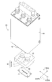
図2~図5に示すように、プラズマヘッド20は、カバー50、上部ブロック52、下部ブロック54、1対の電極56、ノズルブロック58を備えている。カバー50は、概して、有蓋四角筒形状をなしている。カバー50の内部には、上部ブロック52が配設されている。上部ブロック52は、概して直方体形状をなし、セラミックにより形成されている。上部ブロック52の下面には、1対の円柱状の円柱凹部60(図5参照)が形成されている。尚、以下の説明では、図2~図5に示すように、図1に示す上下方向をZ方向、Z方向に垂直な方向をX方向、Z方向及びX方向に垂直な方向をY方向と称して説明する。本実施形態のX方向は、後述する図7に示す照射ブロック140の照射ブロック本体部141の長手方向に沿った方向であり、Y方向は、照射ブロック本体部141の短手方向に沿った方向である。
図2~図5に示すように、プラズマヘッド20は、カバー50、上部ブロック52、下部ブロック54、1対の電極56、ノズルブロック58を備えている。カバー50は、概して、有蓋四角筒形状をなしている。カバー50の内部には、上部ブロック52が配設されている。上部ブロック52は、概して直方体形状をなし、セラミックにより形成されている。上部ブロック52の下面には、1対の円柱状の円柱凹部60(図5参照)が形成されている。尚、以下の説明では、図2~図5に示すように、図1に示す上下方向をZ方向、Z方向に垂直な方向をX方向、Z方向及びX方向に垂直な方向をY方向と称して説明する。本実施形態のX方向は、後述する図7に示す照射ブロック140の照射ブロック本体部141の長手方向に沿った方向であり、Y方向は、照射ブロック本体部141の短手方向に沿った方向である。
また、下部ブロック54は、Z方向に厚い略板状をなし、セラミックにより形成されている。下部ブロック54には、上面から下方へ凹設した凹部62が形成されている。凹部62は、1対の円柱状の円柱凹部66と、それら1対の円柱凹部66を連結する連結凹部68とを有している。下部ブロック54は、カバー50の下端から突出した状態で、上部ブロック52の下面に固定されている。上部ブロック52の円柱凹部60と、下部ブロック54の円柱凹部66とは連通している。円柱凹部60と円柱凹部66とは、略同径とされている。また、凹部62の底面には、下部ブロック54の下面に貫通するスリット70(図4参照)が形成されている。
1対の電極56の各々は、上部ブロック52の円柱凹部60と、下部ブロック54の円柱凹部66とによって区画される円柱状の空間に配設されている。電極56は、略円柱形状をなしている。電極56の外径は、円柱凹部60,66の内径よりも小さくなっている。電極56は、円柱凹部60,66によって区画される空間に配置され、放電によってプラズマガスを発生させる。従って、この円柱凹部60,66によって区画される空間は、本開示の発生室として機能する。
また、ノズルブロック58は、概して平板状をなし、下部ブロック54の下面に固定されている。ノズルブロック58には、下部ブロック54のスリット70と連通する噴出口72が形成されている。噴出口72は、ノズルブロック58を上下方向に貫通している。
プラズマヘッド20は、処理ガス供給装置74(図10参照)に接続されている。処理ガス供給装置74は、例えば、酸素等の活性ガスと窒素等の不活性ガスとを任意の割合で混合させた処理ガスを供給する装置である。この場合、プラズマガスには酸素プラズマが含まれる。処理ガス供給装置74は、円柱凹部60,66によって区画される円柱状の空間及び連結凹部68の上部に、配管(図示省略)を介して連結されている。これにより、電極56と円柱凹部66との隙間、及び連結凹部68の上部から、処理ガスが、凹部62の内部に供給される。
このような構成により、プラズマヘッド20は、ノズルブロック58の噴出口72からプラズマを噴出する。詳しくは、処理ガス供給装置74は、制御装置38(図10参照)の制御に基づいて、凹部62の内部へ処理ガスを供給する。この際、制御装置38は、1対の電極56に電圧を印加する制御を行い、1対の電極56間に電流を流す。これにより、1対の電極56間に放電(例えば、アーク放電)が生じ、その放電により、処理ガスがプラズマ化される。そして、発生したプラズマガスが、スリット70を介して、噴出口72から噴出される。
ここで、本実施形態のプラズマ照射装置10では、プラズマガスだけでなく、放電そのものを被照射液体に当てる。図5に示すように、プラズマヘッド20は、電極56の先端と、噴出口72との間の距離L1が短くなっている。距離L1は、例えば、5.7mmと極めて短くなっている。これにより、噴出口72から放電を外部へと放出することができる。
また、一対の電極56は、X方向(1方向の一例)において、距離L2だけ離れた位置に配置されている。距離L2は、例えば、円柱形状の電極56の中心軸を結ぶ直線の長さである。また、ノズルブロック58の噴出口72は、凹部62からプラズマガスを噴出する出口部分に配置されており、X方向に沿って距離L2だけ形成されたスリット形状をなしている。即ち、一対の電極56間の距離L2と、噴出口72のスリットの長さ(距離L2)とは同一となっている。
これにより、スリット形状の噴出口72により、凹部62(発生室の一例)で発生したプラズマガスの流速を高め、より遠くへ噴出することができる。プラズマガスをより遠くへ噴出させることで、噴出口72からより離れた位置まで放電を発生させることができる。例えば、図8に示すように、プラズマヘッド20と照射ブロック140との距離を短くすることで、放電161を被照射液体により確実に当てることが可能となる。
(カバーハウジングの構成)
図2に示すように、カバーハウジング22は、上部カバー76と、下部カバー78とを備えている。上部カバー76は、概して有蓋円筒状をなしている。上部カバー76の蓋部には、プラズマヘッド20の上部ブロック52に応じた形状の貫通孔79(図6参照)が形成されている。そして、貫通孔79を覆うように、プラズマヘッド20のカバー50が、上部カバー76の蓋部に立設された状態で固定されている。このため、プラズマヘッド20の上部ブロック52が、上部カバー76の内部に向かって、下方へ延びるように、突出している。これにより、プラズマヘッド20によって発生されたプラズマガスが、噴出口72から、上部カバー76の内部に向かって、下方へ噴出される。
図2に示すように、カバーハウジング22は、上部カバー76と、下部カバー78とを備えている。上部カバー76は、概して有蓋円筒状をなしている。上部カバー76の蓋部には、プラズマヘッド20の上部ブロック52に応じた形状の貫通孔79(図6参照)が形成されている。そして、貫通孔79を覆うように、プラズマヘッド20のカバー50が、上部カバー76の蓋部に立設された状態で固定されている。このため、プラズマヘッド20の上部ブロック52が、上部カバー76の内部に向かって、下方へ延びるように、突出している。これにより、プラズマヘッド20によって発生されたプラズマガスが、噴出口72から、上部カバー76の内部に向かって、下方へ噴出される。
下部カバー78は、概して、円板形状とされており、プラズマ照射装置10を載置する載置部の筐体(図示省略)に固定されている。下部カバー78の外径は、上部カバー76の外径より大きくなっている。下部カバー78の上面には、上部カバー76と同径の円環状のパッキン82(図2参照)が下部カバー78の外周に沿って配設されている。上部カバー76は、開閉機構24の駆動に応じて上下方向へスライド移動する。上部カバー76は、開閉機構24によって下方へスライド移動されることで、パッキン82に密着する。カバーハウジング22の内部は、密閉された状態となる。
図6に示すように、上部カバー76には、吸気口130が形成されており、下部カバー78には、排気口135が形成されている。吸気口130は、配管131を介して、パージガス供給装置132(図10参照)と接続されている。パージガス供給装置132は、例えば、アルゴン等の不活性ガスを、カバーハウジング22の内部へ供給する。排気口135には、配管136が接続されている。カバーハウジング22内のガスは、配管136を介して、カバーハウジング22の外へ排気される。プラズマ照射の際には、パージガス供給装置132からカバーハウジング22内に、不活性ガスが供給されて、カバーハウジング22内は不活性ガスでパージされる。これにより、例えば、反応性の高い酸素等の不要な気体を排出したり置き換えたりすることで、カバーハウジング22内を、不活性化ガスで充満させる。
下部カバー78の上には、ステージ26が固定されている。ステージ26の上には、照射ブロック140が設置可能となっている。上部カバー76の側面には、チューブ110が挿通される貫通孔137が形成されている。下部カバー78の底面には、チューブ111が挿通される貫通孔138が形成されている。また、ステージ26には、チューブ111が挿通される貫通孔27が形成されている。また、ステージ昇降装置28は、電磁モータやギア機構等を備え、電磁モータを駆動させギア機構を回転させることで、ステージ26を昇降可能となっている。なお、ステージ昇降装置28は、ユーザによって手動でステージ26の高さを調整可能な構成でも良い。
(照射ブロックの構成)
次に、照射ブロック140について図7及び図8を用いて説明する。照射ブロック140は、概して直方体形状をなす照射ブロック本体部141と、蓋部142とを備えている。尚、図8における左から右へ向かう方向が、被照射液体が流れる方向である。また、上記したように直方体形状の照射ブロック本体部141の長辺方向がX方向であり、短辺方向がY方向である。
次に、照射ブロック140について図7及び図8を用いて説明する。照射ブロック140は、概して直方体形状をなす照射ブロック本体部141と、蓋部142とを備えている。尚、図8における左から右へ向かう方向が、被照射液体が流れる方向である。また、上記したように直方体形状の照射ブロック本体部141の長辺方向がX方向であり、短辺方向がY方向である。
照射ブロック本体部141には、第1溝部143及び第2溝部144が形成されている。第1溝部143は、X方向に沿って形成された溝である。Y方向及びZ方向に沿った平面で第1溝部143を切断した断面は、上方に向かって開口するU字状となっている。第1溝部143の底面143aは、湾曲した形状となっている。チューブ110は、第1溝部143に嵌め込まれることで、照射ブロック140に対して固定される。
第2溝部144は、照射ブロック本体部141を下方へ凹設して形成され、X方向に長い略直方体形状をなしている。第1溝部143及び第2溝部144は、Z方向の上面を開口した溝として形成されている。第1溝部143及び第2溝部144は、ステージ26上に設置された場合に、上方のプラズマヘッド20と対向する面を開放された状態となる。また、第2溝部144の底面144bは、第1溝部143の底面143aよりも下方に下がった位置に形成されている。蓋部142は、概して平板状をなし、照射ブロック本体部141の上に設置されている。
図8に示すように、照射ブロック本体部141は、上記構成の他に、突出部145、排出部146、凹部147、及び係止部141cを有している。以下の説明では、被照射液体の流れる方向を基準として、チューブ110側を上流側、チューブ111側を下流側と称して説明する。突出部145は、第2溝部144の下流側(図8の右側)の側壁に形成されている。突出部145は、底面144bよりも上方に突出している。突出部145の上面145aは、略平面とされている。第2溝部144の上流側には、側壁144cが形成されている。排出部146は、突出部145の下流側に形成されている。排出部146は、排出凹部146a及び排出凸部146bを有する。排出凹部146aは、下方に凹んで形成されている。排出凸部146bは、概して円筒状であり、照射ブロック本体部141の下面141bから下方に突出して形成されている。排出凸部146bは、排出凹部146aと連通している。上面145aの上を通って排出凹部146aへ流れ込む被照射液体は、排出凹部146a及び排出凸部146bを通って下方へ流れる。チューブ111は、排出凸部146bに嵌め込まれて、排出凸部146bに対して固定される。
照射ブロック本体部141の上流側及び下流側には、係止部141cがそれぞれ形成されている。係止部141cは、照射ブロック本体部141の下面141bに対して上方に凹んで形成されている。ステージ26の照射ブロック140が設置される上面には、係止部141c,141cと嵌め合される上方に突出する凸部(不図示)が形成されている。係止部141c,141cと、ステージ26の凸部とが嵌め合されることにより、ステージ26に照射ブロック140が固定される。
照射ブロック140の凹部147は、排出部146の右方に形成されており、照射ブロック本体部141の上面141aよりも下方に凹んで形成されている。蓋部142は、照射ブロック本体部141の突出部145及び凹部147を覆って、照射ブロック本体部141の上方に設置される。蓋部142は、概して平板状をなし、右側に下面142aから下方に突出する凸部142bが形成されている。また、蓋部142における排出部146の上方に対向する部分には、上方に向かって切り欠かれた溝部142cが形成されている。照射ブロック本体部141の凹部147に蓋部142の凸部142bを嵌め込むことで、蓋部142は、照射ブロック本体部141に対して位置決めされる。蓋部142は、昇降装置150(図10参照)によりZ方向に昇降可能となっている。昇降装置150は、照射ブロック本体部141の上面145aと、蓋部142の下面142aとの間に間隙141dを形成した状態で、蓋部142を固定する。
(照射ブロックから保存バッグまでの構成)
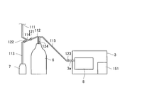
次に、照射ブロック140から流出した照射液体が保存バッグ8に封入されるまでの構成について、図9を用いて説明する。チューブ111は、照射ブロック140の排出部146と分岐管114を接続する。チューブ112は、分岐管114と一次保管ビン6とを接続する。チューブ113は、分岐管114と廃棄ビン7とを接続する。チューブ115は、一次保管ビン6と保存バッグ8とを接続する。チューブ112は、分岐管114から一次保管ビン6へ向かって、上方に傾斜するように取り付けられている。チューブ112,113,115には、それぞれ、バルブ121,122,123が取り付けられている。バルブ121~123は、それぞれ、チューブ112,113,115内の流路を開閉する。また、チューブ115の内部には、滅菌フィルタ124が取り付けられている。これにより、保存バッグ8に封入される前に滅菌フィルタ124によって被照射液体を滅菌できる。充填装置3は、開閉可能に構成され、チューブ115が挿通される貫通孔3aが設けられている。また、充填装置3は、保存バッグ8を収納する内部空間を有し、チューブ115が接続された保存バッグ8を内部空間に収納した状態で内部空間を減圧する減圧装置151を備える。
次に、照射ブロック140から流出した照射液体が保存バッグ8に封入されるまでの構成について、図9を用いて説明する。チューブ111は、照射ブロック140の排出部146と分岐管114を接続する。チューブ112は、分岐管114と一次保管ビン6とを接続する。チューブ113は、分岐管114と廃棄ビン7とを接続する。チューブ115は、一次保管ビン6と保存バッグ8とを接続する。チューブ112は、分岐管114から一次保管ビン6へ向かって、上方に傾斜するように取り付けられている。チューブ112,113,115には、それぞれ、バルブ121,122,123が取り付けられている。バルブ121~123は、それぞれ、チューブ112,113,115内の流路を開閉する。また、チューブ115の内部には、滅菌フィルタ124が取り付けられている。これにより、保存バッグ8に封入される前に滅菌フィルタ124によって被照射液体を滅菌できる。充填装置3は、開閉可能に構成され、チューブ115が挿通される貫通孔3aが設けられている。また、充填装置3は、保存バッグ8を収納する内部空間を有し、チューブ115が接続された保存バッグ8を内部空間に収納した状態で内部空間を減圧する減圧装置151を備える。
(制御系統)
図10に示すように、プラズマ照射装置10は、上記した制御装置38、開閉機構24等の他に、切替部152、残量センサ153、第1温度センサ162、第2温度センサ163を備えている。プラズマ照射装置10は、制御装置38と、プラズマ照射装置10の各部(開閉機構24、ステージ昇降装置28、処理ガス供給装置74、パージガス供給装置132等)が通信可能に接続されている。制御装置38は、コンピュータを主体とするコントローラ170、複数の駆動回路171を有する。コントローラ170は、駆動回路171を介して上記した各部に接続されており、駆動回路171を介して各部の動作を制御する。
図10に示すように、プラズマ照射装置10は、上記した制御装置38、開閉機構24等の他に、切替部152、残量センサ153、第1温度センサ162、第2温度センサ163を備えている。プラズマ照射装置10は、制御装置38と、プラズマ照射装置10の各部(開閉機構24、ステージ昇降装置28、処理ガス供給装置74、パージガス供給装置132等)が通信可能に接続されている。制御装置38は、コンピュータを主体とするコントローラ170、複数の駆動回路171を有する。コントローラ170は、駆動回路171を介して上記した各部に接続されており、駆動回路171を介して各部の動作を制御する。
例えば、コントローラ170は、開閉機構24を制御することで、上部カバー76の開閉を制御する。また、コントローラ170は、ステージ昇降装置28を制御することで、ステージ26のZ方向における位置、即ち、ステージ26の高さを変更する。これにより、ステージ26の高さを、放電が被照射液体に当たる所望の位置に調整することができる。また、コントローラ170は、駆動回路171を介して電極56へ供給する電力を制御する。これにより、放電の発生タイミングを制御することができる。
また、コントローラ170は、駆動回路171を介して処理ガス供給装置74及びパージガス供給装置132から供給する各ガスの流量を制御する。また、コントローラ170は、駆動回路171を介して切替部152を制御し、バルブ121~123を開閉する。これにより、プラズマガスを照射した被照射液体を、一次保管ビン6又は廃棄ビン7の何れに流すかを切替えることができる。また、残量センサ153は、一次保管ビン6に貯留されている被照射液体の量に応じた信号をコントローラ170へ出力する。また、残量センサ153は、保存バッグ8に封入した被照射液体の量に応じた信号をコントローラ170へ出力する。例えば、残量センサ153は、一次保管ビン6に貯留された被照射液体や保存バッグ8に封入された被照射液体の液面高さに応じた信号を出力する。コントローラ170は、例えば、残量センサ153で検出した液面の高さと、予め設定された一次保管ビン6の断面積とに基づいて、一次保管ビン6に貯留されている被照射液体の量を算出することができる。これにより、コントローラ170は、一次保管ビン6や保存バッグ8内の被照射液体の量を制御に用いることができる。
図6に示すように、第1温度センサ162は、照射ブロック140の温度を検出する位置に設けられている。また、第2温度センサ163は、プラズマヘッド20の温度を検出する位置に設けられている。第1及び第2温度センサ162,163は、例えば、赤外線を用いた非接触型の温度センサである。なお、第1及び第2温度センサ162,163は、サーミスタ等を用いた接触型のセンサでも良い。
第1温度センサ162は、照射ブロック140の第1溝部143(上流側)の上方に配置され、照射ブロック140の温度を検出する。照射ブロック140の温度は、被照射液体へのプラズマガスの照射や、被照射液体へ放電161を当てることにより上昇する。第1温度センサ162は、照射ブロック140の温度を示す信号を制御装置38へ出力する。これにより、、制御装置38は、第1温度センサ162の出力信号に基づいて、照射ブロック140の温度を制御に用いることができる。
また、第2温度センサ163は、X方向における上部ブロック52の側方に配置され、プラズマヘッド20の温度を検出する。プラズマヘッド20の温度は、電極56による放電161にともなって上昇する。第2温度センサ163は、プラズマヘッド20の温度を示す信号を制御装置38へ出力する。これにより、制御装置38は、第2温度センサ163の出力信号に基づいて、照射ブロック140の温度を制御に用いることができる。例えば、制御装置38は、プラズマ処理を開始し電極56に電力を供給した後、照射ブロック140の温度やプラズマヘッド20の温度が所望の温度まで上昇しない場合、警告を報知し、電極56への電力供給を停止する。警告の報知方法は、特に限定されないが、ランプの点灯、スピーカからの放音、操作パネルへの警告表示などの方法を採用できる。警告をユーザに認識させることで、プラズマ照射装置10の状態を確認するなどの対応をユーザへ促すことができる。
なお、上記した第1及び第2温度センサ162,163の取り付け位置は、一例であり、適宜変更可能である。例え、第1温度センサ162は、照射ブロック140の下面141b(図8参照)の温度を検出する構成でも良い。また、プラズマ照射装置10は、第1温度センサ162又は第2温度センサ163の一方のみを備える構成でも良い。また、制御装置38は、第1及び第2温度センサ162,163による異常温度の検出に応じて、電極56へ印加する電力、処理ガス供給装置74から供給するガスの供給量、ステージ昇降装置28によるステージ26の高さ等を変更し、条件を変更してから再度プラズマ処理を自動的に実行しても良い。
従って、本実施形態のプラズマ照射装置10は、プラズマガスの照射に係わる温度を検出する第1及び第2温度センサ162,163を備える。これによれば、第1及び第2温度センサ162,163で検出した温度に基づいてプラズマガス及び放電161が被照射液体に対して適切に放出されているか否か、即ち、プラズマ処理を適切に実行できているか否かを判断できる。
また、第1温度センサ162は、プラズマヘッド20(プラズマ発生装置の一例)の温度を検出する。これによれば、プラズマヘッド20の温度を検出することで、プラズマヘッド20が所望の温度まで上昇しているか否か、即ち、放電161を適切に発生させているか否かを判断できる。また、第2温度センサ163は、ステージ26に載置され被照射液体を流す第1溝部143や第2溝部144(溝部の一例)を形成された照射ブロック140の温度を検出する。これによれば、照射ブロック140の温度を検出することで、プラズマガスや放電161によって照射ブロック140の温度が上昇しているか否か、即ち、プラズマガスや放電161が被照射液体まで適切に到達しているか否かを判断できる。
また、制御装置38は、駆動回路171を介して流量調整器5(図1参照)を制御し、液体バッグ2から照射ブロック140へ供給する被照射液体の流量を変更する。また、制御装置38は、流量調整器5を制御することで、必要に応じて被照射液体の供給を開始又は停止することができる。なお、流量調整器5は、手動でのみ流量を変更可能な構成でも良い。
(プラズマ処理工程)
次に、プラズマ照射装置10によるプラズマ処理の動作について説明する。尚、下記の処理工程の順番や内容は、一例である。また、本実施形態では、被照射液体としてラクテック(登録商標)を採用できる。プラズマガスを照射して活性化したラクテックは、体内に注入することにより病巣を治療する医療に用いることができる。このため、被照射液体は、滅菌された状態でプラズマ処理を施されることが好ましい。
次に、プラズマ照射装置10によるプラズマ処理の動作について説明する。尚、下記の処理工程の順番や内容は、一例である。また、本実施形態では、被照射液体としてラクテック(登録商標)を採用できる。プラズマガスを照射して活性化したラクテックは、体内に注入することにより病巣を治療する医療に用いることができる。このため、被照射液体は、滅菌された状態でプラズマ処理を施されることが好ましい。
まず、例えば、制御装置38は、プラズマ処理の開始を指示されると、開閉機構24を制御して上部カバー76を下方させ、カバーハウジング22の内部を密閉した状態にする。制御装置38は、例えば、予め設定された設定値に基づいて、ステージ昇降装置28を制御し、ステージ26(照射ブロック140)を所望の高さに調整する。これにより、照射ブロック140とプラズマヘッド20との間の距離L3(図6参照)を所望の高さに調整することができる。即ち、プラズマヘッド20から放出される放電161を被照射液体に当てることが可能な所望の距離L3に調整できる。
従って、本実施形態のプラズマ照射装置10は、ステージ26を移動させ、被照射液体と噴出口72との間の距離L3を変更可能に構成され、被照射液体と噴出口72との間の距離L3を、放電161が被照射液体に到達する距離に変更するステージ昇降装置28(移動装置の一例)を備える。これによれば、被照射液体を配置したステージ26を、放電161が被照射液体に当たる所望の位置へステージ昇降装置28によって移動させることができる。これにより、被照射液体をより均質に活性化することができる。
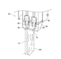
図11は、照射ブロック140及びステージ26を配置しない状態で、プラズマヘッド20から放電161を放出させた状態を示している。図11に示すように、放電161は、例えば、噴出口72から所定の距離L4まで放出される。放電161は、例えば、プラズマガスや処理ガスなどの各種ガスと混在した状態で放出され、導電性の高いガスを通じて放電を発生させる。この距離L4は、様々な条件によって変動する。本実施形態のプラズマヘッド20では、上記したように、電極56と噴出口72との間の距離L1(図5参照)を短くすることで、一対の電極56間で発生する放電161を噴出口72の外へ出し易くし、距離L4をより長くすることが可能となる。また、本実施形態のプラズマヘッド20では、上記したように、噴出口72を一対の電極56の対向方向(X方向)に沿ったスリット形状とし、且つ一対の電極56間の距離L2と噴出口72のスリットの長さを同一にしている。これにより、距離L4をより長くすることが可能となる。
図12は、照射ブロック140を配置した状態で、プラズマヘッド20から放電161を放出させた状態を示している。また、図12は、照射ブロック140の第2溝部144に被照射液体165を貯留させた状態を示している。図12に示すように、本実施形態のプラズマ照射装置10において、例えば、照射ブロック140に貯留した被照射液体165の表面と噴出口72との距離L5を、図11に示す距離L4に比べて極めて短くしている。例えば、距離L5は、距離L4の1/5以下の長さである。従って、照射ブロック140を配置しない状態(図11)で放電161やプラズマガスを放出した照射距離(距離L4)に比べて、照射ブロック140をプラズマヘッド20に近接させる。このため、図12に示すように、照射ブロック140の第2溝部144に貯留された被照射液体165は、噴出口72に近接した位置に配置される。そして、放電161やプラズマガスは、図12に示す状態では、図11に示す状態における照射方向(Z方向)のより根元の部分(図11の上方部分)で被照射液体165に到達する状態となっている。これにより、より高エネルギーを被照射液体165に与えながらプラズマ処理を行うことができ、被照射液体165をより均一に活性化できる。
処理工程の説明に戻り、制御装置38は、カバーハウジング22の内部を密閉し、ステージ26の高さを調整した後、パージガス供給装置132を制御して不活性ガスをカバーハウジング22内へ供給し、カバーハウジング22内を不活性ガスでパージさせる。これにより、放電161やプラズマガスを放出する距離L4(図11参照)をより長くすることができ、高エネルギーを被照射液体165に与え被照射液体165をより均質に活性化できる。また、制御装置38は、処理ガス供給装置74を制御して処理ガスを供給させる。制御装置38は、電極56に電力を供給してプラズマヘッド20からプラズマガスの照射を開始させる。制御装置38は、流量調整器5を制御し、一定の流量で被照射液体165をチューブ110へ流す。
図8に示すように、第2溝部144は、左端に側壁144cが形成され、右端に突出部145が形成されている。被照射液体165は、図8において破線で示す突出部145の上面145aの高さ程度まで第2溝部144内に貯留される。第2溝部144に貯留された被照射液体165は、プラズマヘッド20からプラズマガスが照射されて活性化される。また、本実施形態の制御装置38は、ステージ昇降装置28を制御することにより、プラズマヘッド20と被照射液体165(照射ブロック140)との距離L3(図6参照)を予め設定された距離に調整する。これにより、噴出口72から放出された放電161を被照射液体165に適切に当てることが可能となる。
被照射液体165は、第2溝部144に貯留されることにより、所定時間だけプラズマガスを照射される。被照射液体165に所定時間、プラズマガス及び放電161を放出することで、プラズマ照射された被照射液体165による治療効果が発揮されることがわかっている。特に、放電161を直接当てたラクテックは、がん細胞を選択的に殺傷する効能をより高めることが可能となる。被照射液体165は、プラズマガスを照射されることにより、第2溝部144内で自然対流する。これにより、上記した治療効果が発揮される活性化された被照射液体165を生成できる。以下の説明において、第2溝部144を通過した後の被照射液体165を既照射液体と記載する場合がある。
毛細管現象により、既照射液体は、上面145aと下面142aとの間に形成された間隙141dを伝って、排出凹部146aを経由して排出凸部146bから下方へ流出する。照射ブロック本体部141から流出される既照射液体の流出量は、間隙141dの幅により決定される。このため、制御装置38は、昇降装置150を制御し、所望の流出量(ユーザによる設定値等)に応じた幅となるように、蓋部142の高さを調整する。
図9に示すように、照射ブロック140から流出した既照射液体は、チューブ111内を流れる。ここで、制御装置38は、プラズマガスの照射の開始時には、バルブ121を閉状態に、バルブ122を開状態に制御する。これにより、既照射液体は、チューブ113を介して廃棄ビン7へ流れる。そして、制御装置38は、プラズマガスの照射の開始から所定時間経過後に、バルブ121を開状態に、バルブ122を閉状態に切替える。これにより、既照射液体は、チューブ112を介して一次保管ビン6へ流れる。流れる被照射液体165にプラズマガスを照射する場合、プラズマ照射の開始直後から所定時間内に流れる既照射液体は、十分に活性化されていない虞がある。そこで、本実施形態のプラズマ照射装置10では、プラズマ照射の開始直後から所定時間の間は、既照射液体を廃棄ビン7へ流し、所定時間だけ経過した後に、既照射液体を一次保管ビン6へ流す。これにより、十分に活性化された既照射液体を、一次保管ビン6に貯留できる。また、チューブ112は、分岐管114から一次保管ビン6へ向かって上方に傾斜するように取り付けられている。チューブ113は、分岐管114から廃棄ビン7へ向かって下方に傾斜するように取り付けられている。これにより、活性化の不十分な既照射液体が、一次保管ビン6へ混入することを抑制できる。
制御装置38は、残量センサ153の出力信号に基づいて、例えば一次保管ビン6に貯留された既照射液体の量が所定の量に達したことを検出すると、流量調整器5及びバルブ121,122を閉じ、プラズマヘッド20のプラズマ照射を停止させる。制御装置38は、一次保管ビン6に貯留された既照射液体を保存バッグ8へ封入する作業を開始する。制御装置38は、切替部152を制御し、バルブ123を閉状態から開状態に切替える。制御装置38は、減圧装置151を制御し、充填装置3の内部の気圧を大気圧から減圧させることで、一次保管ビン6から保存バッグ8へ既照射液体を封入する。制御装置38は、残量センサ153の出力信号に基づいて、保存バッグ8に封入された既照射液体の量が所定の量に達したと判断すると、減圧装置151を制御し、充填装置3の内部の気圧を大気圧に戻す。これにより、所定量の既照射液体を保存バッグ8に封入できる。ユーザは、例えば、封入済みの保存バッグ8を新たな保存バッグ8へ交換し、再度プラズマ照射装置10の運転を開始させる。尚、プラズマ照射装置10は、保存バッグ8の1袋ごとにプラズマヘッド20等を停止させずに、プラズマ処理を実行しながら、自動で保存バッグ8を交換する構成でも良い。
上記実施形態において、プラズマヘッド20は、プラズマ発生装置の一例である。ステージ昇降装置28は、移動装置の一例である。凹部62は、発生室の一例である。第1溝部143及び第2溝部144は、溝部の一例である。第1温度センサ162及び第2温度センサ163は、温度センサの一例である。X方向は、第1方向の一例である。距離L2は、第1距離の一例である。
以上、説明した実施形態によれば、以下の効果を奏する。
本実形態の一態様では、プラズマヘッド20は、ノズルブロック58の噴出口72から放出させ被照射液体165に到達する放電161を発生させる(図8参照)。これによれば、被照射液体165に対しプラズマガスだけでなく、放電161そのものを当てる。これにより、より高エネルギーを被照射液体165に与えながらプラズマ処理を行うことで、被照射液体165をより均一に活性化できる。例えば、被照射液体165としてラクテック(登録商標)と同一成分の水溶液を用いた場合、プラズマ処理によってプラズマ活性溶液(PAL:PlasmaActivated Lactec)を生成することで、がん細胞を選択的に殺傷する効能をPALに対して付加することが可能となる。この効能を、被照射液体165に放電161を直接当てることで、より高めることが可能となる。
本実形態の一態様では、プラズマヘッド20は、ノズルブロック58の噴出口72から放出させ被照射液体165に到達する放電161を発生させる(図8参照)。これによれば、被照射液体165に対しプラズマガスだけでなく、放電161そのものを当てる。これにより、より高エネルギーを被照射液体165に与えながらプラズマ処理を行うことで、被照射液体165をより均一に活性化できる。例えば、被照射液体165としてラクテック(登録商標)と同一成分の水溶液を用いた場合、プラズマ処理によってプラズマ活性溶液(PAL:PlasmaActivated Lactec)を生成することで、がん細胞を選択的に殺傷する効能をPALに対して付加することが可能となる。この効能を、被照射液体165に放電161を直接当てることで、より高めることが可能となる。
尚、本開示は上記実施形態に限定されるものではなく、本開示の趣旨を逸脱しない範囲内での種々の改良、変更が可能であることは言うまでもない。
例えば、上記実施形態のプラズマヘッド20の構成は、一例である。例えば、上記実施形態では、下部ブロック54と噴出口72とが別の部材であったが、1つの部材でも良い。
また、プラズマ照射装置10は、第1及び第2温度センサ162,163を備えなくとも良い。また、プラズマ照射装置10は、第1及び第2温度センサ162,163の一方のみを備える構成でも良い。
また、制御装置38は、第1及び第2温度センサ162,163により検出した温度の判断等を実行せずに、検出した温度を表示する処理のみを実行しても良い。
また、上記実施形態では、制御装置38は、開閉機構24による上部カバー76の位置調整や、ステージ昇降装置28によるステージ26の位置調整を実行したが、このような自動調整を実行しない構成でも良い。プラズマ照射装置10は、例えば、ステージ26の位置を、手動によってのみ変更可能な構成でも良い。
また、噴出口72は、スリット形状以外の形状、例えば、メッシュ形状でも良い。また、噴出口72の開口(スリット)の長さは、電極56の距離L2とは異なる長さでも良い。
例えば、上記実施形態のプラズマヘッド20の構成は、一例である。例えば、上記実施形態では、下部ブロック54と噴出口72とが別の部材であったが、1つの部材でも良い。
また、プラズマ照射装置10は、第1及び第2温度センサ162,163を備えなくとも良い。また、プラズマ照射装置10は、第1及び第2温度センサ162,163の一方のみを備える構成でも良い。
また、制御装置38は、第1及び第2温度センサ162,163により検出した温度の判断等を実行せずに、検出した温度を表示する処理のみを実行しても良い。
また、上記実施形態では、制御装置38は、開閉機構24による上部カバー76の位置調整や、ステージ昇降装置28によるステージ26の位置調整を実行したが、このような自動調整を実行しない構成でも良い。プラズマ照射装置10は、例えば、ステージ26の位置を、手動によってのみ変更可能な構成でも良い。
また、噴出口72は、スリット形状以外の形状、例えば、メッシュ形状でも良い。また、噴出口72の開口(スリット)の長さは、電極56の距離L2とは異なる長さでも良い。
10 プラズマ照射装置、20 プラズマヘッド(プラズマ発生装置)、26 ステージ、28 ステージ昇降装置(移動装置)、56 電極、58 ノズルブロック、62 凹部(発生室)、72 噴出口、140 照射ブロック、143 第1溝部(溝部)、144 第2溝部(溝部)、161 放電、162 第1温度センサ(温度センサ)、163 第2温度センサ(温度センサ)、165 被照射液体、L2 距離(第1距離)、L3 距離。
Claims (5)
- プラズマガスを照射する被照射液体を配置するステージと、
放電により前記プラズマガスを発生させる一対の電極と、前記プラズマガスを前記被照射液体に向けて噴出する噴出口を有するノズルブロックと、を有し、前記噴出口から放出させ前記被照射液体に到達する前記放電を発生させるプラズマ発生装置と、
を備えるプラズマ照射装置。 - 前記プラズマガスの照射に係わる温度を検出する温度センサを備える、請求項1に記載のプラズマ照射装置。
- 前記温度センサは、
前記プラズマ発生装置、及び前記ステージに載置され前記被照射液体を流す溝部を形成された照射ブロックのうち、少なくとも一方の温度を検出する、請求項2に記載のプラズマ照射装置。 - 前記ステージを移動させ、前記被照射液体と前記噴出口との間の距離を変更可能に構成され、前記被照射液体と前記噴出口との間の距離を、前記放電が前記被照射液体に到達する距離に変更する移動装置を備える、請求項1乃至請求項3の何れか1項に記載のプラズマ照射装置。
- 前記プラズマ発生装置は、
前記一対の電極を配置され、前記一対の電極の前記放電により前記プラズマガスを発生させる発生室を有し、
前記一対の電極は、
第1方向において第1距離だけ離れた位置に配置され、
前記噴出口は、
前記発生室から前記プラズマガスが噴出される出口に配置され、前記第1方向に沿って前記第1距離だけ形成されたスリット形状である、請求項1乃至請求項4の何れか1項に記載のプラズマ照射装置。
Priority Applications (2)
| Application Number | Priority Date | Filing Date | Title |
|---|---|---|---|
| PCT/JP2018/042278 WO2020100252A1 (ja) | 2018-11-15 | 2018-11-15 | プラズマ照射装置 |
| JP2020556525A JP7113909B2 (ja) | 2018-11-15 | 2018-11-15 | プラズマ照射装置 |
Applications Claiming Priority (1)
| Application Number | Priority Date | Filing Date | Title |
|---|---|---|---|
| PCT/JP2018/042278 WO2020100252A1 (ja) | 2018-11-15 | 2018-11-15 | プラズマ照射装置 |
Publications (1)
| Publication Number | Publication Date |
|---|---|
| WO2020100252A1 true WO2020100252A1 (ja) | 2020-05-22 |
Family
ID=70731412
Family Applications (1)
| Application Number | Title | Priority Date | Filing Date |
|---|---|---|---|
| PCT/JP2018/042278 Ceased WO2020100252A1 (ja) | 2018-11-15 | 2018-11-15 | プラズマ照射装置 |
Country Status (2)
| Country | Link |
|---|---|
| JP (1) | JP7113909B2 (ja) |
| WO (1) | WO2020100252A1 (ja) |
Families Citing this family (1)
| Publication number | Priority date | Publication date | Assignee | Title |
|---|---|---|---|---|
| US20080270723A1 (en) * | 2004-11-26 | 2008-10-30 | Makoto Ueda | Multiprocessor System and Exclusive Control Method Therefor |
Citations (2)
| Publication number | Priority date | Publication date | Assignee | Title |
|---|---|---|---|---|
| JP2006277953A (ja) * | 2005-03-25 | 2006-10-12 | Toyohashi Univ Of Technology | プラズマ生成装置、プラズマ処理装置、プラズマ生成方法及びプラズマ処理方法 |
| JP2007287454A (ja) * | 2006-04-14 | 2007-11-01 | Seiko Epson Corp | プラズマ装置 |
Family Cites Families (4)
| Publication number | Priority date | Publication date | Assignee | Title |
|---|---|---|---|---|
| JP2001269422A (ja) | 2000-03-27 | 2001-10-02 | Jeol Ltd | 有害物質処理装置 |
| JP5948531B2 (ja) | 2011-07-06 | 2016-07-06 | 名古屋市 | プラズマ処理装置及び処理方法 |
| US10513790B2 (en) | 2014-12-17 | 2019-12-24 | UNIVERSITé LAVAL | Dielectric barrier discharge plasma method and apparatus for synthesizing metal particles |
| JP6583882B2 (ja) | 2015-08-05 | 2019-10-02 | 国立大学法人名古屋大学 | 魚類の生産方法および稚魚の成長促進方法および魚類の成長促進剤 |
-
2018
- 2018-11-15 WO PCT/JP2018/042278 patent/WO2020100252A1/ja not_active Ceased
- 2018-11-15 JP JP2020556525A patent/JP7113909B2/ja active Active
Patent Citations (2)
| Publication number | Priority date | Publication date | Assignee | Title |
|---|---|---|---|---|
| JP2006277953A (ja) * | 2005-03-25 | 2006-10-12 | Toyohashi Univ Of Technology | プラズマ生成装置、プラズマ処理装置、プラズマ生成方法及びプラズマ処理方法 |
| JP2007287454A (ja) * | 2006-04-14 | 2007-11-01 | Seiko Epson Corp | プラズマ装置 |
Also Published As
| Publication number | Publication date |
|---|---|
| JP7113909B2 (ja) | 2022-08-05 |
| JPWO2020100252A1 (ja) | 2021-09-02 |
Similar Documents
| Publication | Publication Date | Title |
|---|---|---|
| KR101273764B1 (ko) | 멸균제 주입기 및 이를 포함하는 멸균 장치 | |
| US9248654B2 (en) | Fluid ejection device | |
| JP2010013166A (ja) | 真空包装装置 | |
| JP7113909B2 (ja) | プラズマ照射装置 | |
| CN105592937A (zh) | 液体材料填充装置及方法 | |
| KR102476398B1 (ko) | 플라즈마 처리 장치 및 이를 이용한 방법 | |
| WO2020026324A1 (ja) | 大気圧プラズマ処理装置 | |
| US20150238216A1 (en) | Fluid ejecting apparatus and medical device | |
| US20090053101A1 (en) | Sterilization Method and Plasma Sterilization Apparatus | |
| KR20210068922A (ko) | 보철물 접합 촉진을 위한 저온 대기압 플라즈마 발생장치 | |
| JP2010046226A (ja) | アイソレータ | |
| WO2018037468A1 (ja) | プラズマ照射装置、および、プラズマ照射方法 | |
| KR20230041562A (ko) | 플라즈마 표면처리 장치 및 이를 이용한 플라즈마 표면처리 방법 | |
| WO2017037775A1 (ja) | プラズマ照射装置 | |
| WO2007006348A9 (en) | Dosing safety arrangement in a delivery apparatus for pressurised medical liquids | |
| WO2013061654A1 (ja) | 溶解液生成装置およびオゾン水生成装置、並びに、それを備えた衛生器具用洗浄装置 | |
| KR20180057809A (ko) | 저온 대기압 플라즈마 발생장치 | |
| JP2008289523A (ja) | 携帯型動物用オゾン治療装置 | |
| KR100489636B1 (ko) | 의료용 오존시스템 | |
| JP7682292B2 (ja) | プラズマ照射装置及びプラズマ処理液体製造方法 | |
| JP6823656B2 (ja) | 抗腫瘍水溶液製造装置 | |
| JP7787975B2 (ja) | プラズマ照射装置、およびプラズマ処理液体製造方法 | |
| WO2023073878A1 (ja) | プラズマ照射装置及びプラズマ処理液体製造方法 | |
| US20250168960A1 (en) | Method for producing plasma processed liquid and plasma irradiation apparatus | |
| KR20110042556A (ko) | 알루미늄 플럭스 자동 주입 장치 |
Legal Events
| Date | Code | Title | Description |
|---|---|---|---|
| 121 | Ep: the epo has been informed by wipo that ep was designated in this application |
Ref document number: 18940236 Country of ref document: EP Kind code of ref document: A1 |
|
| ENP | Entry into the national phase |
Ref document number: 2020556525 Country of ref document: JP Kind code of ref document: A |
|
| NENP | Non-entry into the national phase |
Ref country code: DE |
|
| 122 | Ep: pct application non-entry in european phase |
Ref document number: 18940236 Country of ref document: EP Kind code of ref document: A1 |