WO2020100209A1 - Peripheral nerve examination device, peripheral nerve examination method, and program - Google Patents
Peripheral nerve examination device, peripheral nerve examination method, and program Download PDFInfo
- Publication number
- WO2020100209A1 WO2020100209A1 PCT/JP2018/041959 JP2018041959W WO2020100209A1 WO 2020100209 A1 WO2020100209 A1 WO 2020100209A1 JP 2018041959 W JP2018041959 W JP 2018041959W WO 2020100209 A1 WO2020100209 A1 WO 2020100209A1
- Authority
- WO
- WIPO (PCT)
- Prior art keywords
- subject
- peripheral nerve
- stimulus
- reaction time
- unit
- Prior art date
Links
Images


Classifications
-
- A—HUMAN NECESSITIES
- A61—MEDICAL OR VETERINARY SCIENCE; HYGIENE
- A61B—DIAGNOSIS; SURGERY; IDENTIFICATION
- A61B5/00—Measuring for diagnostic purposes; Identification of persons
- A61B5/40—Detecting, measuring or recording for evaluating the nervous system
- A61B5/4029—Detecting, measuring or recording for evaluating the nervous system for evaluating the peripheral nervous systems
- A61B5/4041—Evaluating nerves condition
- A61B5/4047—Evaluating nerves condition afferent nerves, i.e. nerves that relay impulses to the central nervous system
-
- A—HUMAN NECESSITIES
- A61—MEDICAL OR VETERINARY SCIENCE; HYGIENE
- A61B—DIAGNOSIS; SURGERY; IDENTIFICATION
- A61B5/00—Measuring for diagnostic purposes; Identification of persons
- A61B5/16—Devices for psychotechnics; Testing reaction times ; Devices for evaluating the psychological state
- A61B5/162—Testing reaction times
-
- A—HUMAN NECESSITIES
- A61—MEDICAL OR VETERINARY SCIENCE; HYGIENE
- A61B—DIAGNOSIS; SURGERY; IDENTIFICATION
- A61B5/00—Measuring for diagnostic purposes; Identification of persons
- A61B5/48—Other medical applications
- A61B5/4824—Touch or pain perception evaluation
-
- A—HUMAN NECESSITIES
- A61—MEDICAL OR VETERINARY SCIENCE; HYGIENE
- A61B—DIAGNOSIS; SURGERY; IDENTIFICATION
- A61B5/00—Measuring for diagnostic purposes; Identification of persons
- A61B5/74—Details of notification to user or communication with user or patient ; user input means
- A61B5/742—Details of notification to user or communication with user or patient ; user input means using visual displays
- A61B5/743—Displaying an image simultaneously with additional graphical information, e.g. symbols, charts, function plots
-
- A—HUMAN NECESSITIES
- A61—MEDICAL OR VETERINARY SCIENCE; HYGIENE
- A61N—ELECTROTHERAPY; MAGNETOTHERAPY; RADIATION THERAPY; ULTRASOUND THERAPY
- A61N1/00—Electrotherapy; Circuits therefor
- A61N1/02—Details
- A61N1/04—Electrodes
- A61N1/05—Electrodes for implantation or insertion into the body, e.g. heart electrode
- A61N1/0502—Skin piercing electrodes
-
- A—HUMAN NECESSITIES
- A61—MEDICAL OR VETERINARY SCIENCE; HYGIENE
- A61N—ELECTROTHERAPY; MAGNETOTHERAPY; RADIATION THERAPY; ULTRASOUND THERAPY
- A61N1/00—Electrotherapy; Circuits therefor
- A61N1/02—Details
- A61N1/04—Electrodes
- A61N1/05—Electrodes for implantation or insertion into the body, e.g. heart electrode
- A61N1/0551—Spinal or peripheral nerve electrodes
Definitions
- the present disclosure relates to a peripheral nerve testing apparatus, a peripheral nerve testing method, and a program for testing a peripheral nerve of a subject.
- Patent Document 1 is known as a technique for performing a peripheral nerve examination with a simple configuration.
- Patent Document 1 discloses a pain sensory nerve stimulator capable of selectively stimulating only C fibers.
- Patent Document 1 An example of a device to which Patent Document 1 is applied is a peripheral nerve examination device introduced in Non-Patent Document 1.
- the subject is attached with electrodes for stimulation and the switch is grasped, and the examiner operates the peripheral nerve testing apparatus to set the current value to be output and to output the stimulation output. To do.
- the subject presses the switch when feeling the stimulus.
- the peripheral nerve testing apparatus tests the normality of the peripheral nerve of the subject based on the current value and the reaction time (time from the start of stimulation to the time when the switch is pressed).
- the peripheral nerve can be inspected with a simple configuration without attaching electrodes to the scalp unlike the electroencephalography.
- Portable peripheral nerve testing device PNS-7000 [Search on September 25, 2017], Internet ⁇ URL: http://www.nihonkohden.co.jp/iryo/documents/pdf/H901653C.pdf> Atsushi Kimura, Nobuo Yukihara, "For those who study nerve conduction tests and electromyography", Medical Institute Koji Inui, Ryusuke Kakigi, “Pain reception in inhumanhumans: use of intraepidermal electrical stimulation”, J Neurol Neurosurg Psychiatry 83: 551-556, 2012.
- the reaction time of the subject is measured for each of multiple stimuli while changing the intensity of the stimulus. Then, it is general to examine the nervous system of the subject based on the minimum intensity of the stimulus and the reaction time that the subject can detect.
- the reaction time to the stimulus is determined according to the pressing of the subject's switch (and thus the expression of sensing). Therefore, the subject may make an operation error, or the subject's approach to the examination may be inappropriate.
- the reaction time of each stimulus with different intensities was not appropriate, the minimum sensed current value happened to be a normal value, so that the subject could be examined normally. There was a fear that I would have been broken. That is, in the test using only the minimum sensed stimulus intensity as a criterion, there is a problem that it is not known whether a normal test is performed.
- the present disclosure can determine whether or not a normal test is performed when a test of a peripheral nerve of the test subject is performed based on an expression of sensing a stimulus by the test subject (for example, pressing a switch).
- the main object is to provide a peripheral nerve inspection apparatus, a peripheral nerve inspection method, and a program.
- a device for examining peripheral nerves of the subject based on the expression of the sensed stimulus by the subject A stimulus control unit that gives the subject a plurality of stimuli of varying intensities, For each of the plurality of stimuli, a measurement unit that measures the measured value of the reaction time of the subject, And an output unit that outputs the relationship of the change in the measured value with respect to the change in the intensity of the stimulus.
- the peripheral nerve testing device is configured to output the relationship between changes in measured reaction time and changes in stimulation intensity.
- the examiner can easily determine whether or not the examination is normally performed (whether or not the examination of the peripheral nerve is normally performed) by referring to the output information.
- FIG. 1 is a block diagram showing a configuration of a peripheral nerve examination apparatus 1 according to a first exemplary embodiment.
- 6 is an example of an output screen (during a normal inspection) by the output unit 14 according to the first embodiment.
- 4 is an example of an output screen (at the time of abnormality inspection) by the output unit 14 according to the first embodiment.
- 6 is an example of an output screen (during a normal inspection) by the output unit 14 according to the first embodiment.
- FIG. 6 is a block diagram showing a configuration of a peripheral nerve examination apparatus 1 according to a second exemplary embodiment.
- FIG. 3 is a diagram showing a hardware configuration of a peripheral nerve examination apparatus 1 according to the first or second embodiment.
- Non-Patent Documents 3 and 4 There are multiple types of nerve fibers (C fibers, A delta fibers, etc.). It is known that C fibers are more likely to be excited by electrical stimulation than A ⁇ fibers (Non-Patent Documents 3 and 4). For example, Non-Patent Document 3 shows that C fibers responded to laser stimulation at about 40 ° C. and A ⁇ fibers reacted at about 46 ° C. That is, it was shown that the C fibers responded to a weaker stimulus than the A ⁇ fibers. This is because the C fibers are more likely to respond to even weaker stimuli because the nerves extend to the periphery more than the A ⁇ fibers (Non-Patent Document 5 Fig. 5B). is there.
- the conduction time varies depending on the type of nerve fiber (Non-patent document 2).
- the conduction velocity of A ⁇ fibers is about 10 to 30 m / s
- the conduction velocity of C fibers is about 0.5 to 2.5 m / s.
- the A ⁇ fiber also responds to the stimulus, and the conduction velocity becomes faster. That is, the time from giving a stimulus to recognizing the stimulus becomes shorter.
- the following peripheral nerve examination apparatus 1 performs the operation based on this characteristic.
- FIG. 1 is a block diagram showing the configuration of a peripheral nerve examination apparatus 1 according to this embodiment.
- the peripheral nerve examination apparatus 1 is an apparatus that evaluates the peripheral nerves of the subject based on the expression of the sensed stimulus by the subject. More specifically, the peripheral nerve examination apparatus 1 applies stimulation to the peripheral nerves of the subject via the electrodes 30. When the subject feels the stimulus, he / she expresses that he / she feels the stimulus by operating the operation unit 20 (preferably a grip type switch). The peripheral nerve examination apparatus 1 evaluates the peripheral nerve of the subject based on the measured values of the intensity of the applied stimulation and the reaction time (time from the start of stimulation to the time when the operation unit 20 is operated). The detailed configuration will be described below.
- the peripheral nerve examination apparatus 1 has a main body 10 and an operation unit 20.
- the main body 10 and the operation unit 20 are connected by a general cable. Further, the main body 10 is configured to be attachable to and detachable from the disposable electrode 30.
- the electrode 30 is one aspect of a member that stimulates the peripheral nerves of the subject, and is, for example, a disposable electrode that can be attached to the skin of the subject.
- the electrode 30 is a first electrode that is used by slightly sticking the tip into the skin of the subject, and a first electrode that is disposed around the first electrode and is brought into contact with the skin of the subject. It may be configured with two electrodes.
- a probe for stimulating the peripheral nerve of the subject may be connected to the main body 10.
- the main body 10 is preferably a casing having a size that can be held by an inspector (for example, a medical worker).
- the input unit 15 and the display 16 are arranged on the housing of the main body 10.
- the input unit 15 is a button, a scroll wheel, or the like provided on the housing of the main body unit 10.
- the examiner operates the input unit 15 to input arbitrary settings, stimulus start cues, and the like.
- the display 16 is a liquid crystal display provided on the housing of the main body 10.
- the main body 10 may also include a speaker and a power source (not shown). Further, the display 16 may have a form having a function of the input unit 15 (so-called touch display).
- the operation unit 20 is an interface operated by a subject who undergoes a peripheral nerve examination.
- the operation part 20 is a grip type switch gripped by the subject.
- various electric circuits and the like for transmitting a detection signal to the main body unit 10 when a switch is pressed are arranged.
- the detection signal is input to the main body 10 via the cable.
- the subject operates the operation unit 20 when the stimulus is sensed through the electrode 30 and notifies the main body unit 10 that the stimulus is sensed (in other words, the subject expresses that the stimulus is sensed). ).
- the main body unit 10 includes a control unit 11.
- the control unit 11 is a processing unit that performs various controls of the peripheral nerve examination apparatus 1, and includes a measurement unit 12, a stimulation control unit 13, and an output unit 14.
- the stimulus control unit 13 controls the intensity and timing of the stimulus given via the electrode 30.
- the stimulus control unit 13 gives the subject a plurality of stimuli of varying intensities via the electrodes 30.
- the strength of the stimulus may be controlled by the magnitude of the current value and the voltage value.
- the intensity of stimulation is controlled by changing the current value.
- the examiner can set the change in the intensity of the stimulus controlled by the stimulus control unit 13 and the number of stimuli through the input unit 15.
- the examiner inputs, for example, the current value of the first stimulation, the increment / decrement unit of the current value, the number of stimulations, and the like via the input unit 15. Further, the examiner may input the current value and the stimulation timing for each stimulation via the input unit 15.
- the stimulation control unit 13 executes electrical stimulation a plurality of times via the electrodes 30 based on the input information such as the current value.
- the stimulus control unit 13 may control the output of the stimulus so that the intensity gradually increases, or may control the output of the stimulus so that the intensity gradually decreases.
- the measuring unit 12 measures the measurement value of the reaction time for each of multiple stimulations given through the electrode 30.
- the measurement unit 12 may calculate the measurement value of the reaction time for each stimulation using the notification signal of the stimulation start by the stimulation control unit 13 and the detection signal input from the operation unit 20, for example.
- the output unit 14 acquires the measurement value of the reaction time for each stimulus measured by the measurement unit 12.
- the output unit 14 also acquires information on the intensity of each stimulation controlled by the stimulation control unit 13. That is, the output unit 14 acquires a set of the intensity of each stimulus and the measured value of the reaction time.
- the output unit 14 outputs the relationship between the intensity of each stimulus and the measured value of the reaction time for each stimulus for multiple stimuli.
- the output part 14 outputs the data for displaying the relationship between the intensity
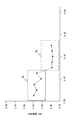
- FIG. 2 shows a two-dimensional graph when the peripheral nerve examination of the subject is normally performed
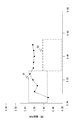
- FIG. 3 shows a two-dimensional graph when the peripheral nerve examination of the subject is not normally performed.
- the intensity (current value) of the stimulus is displayed on the horizontal axis (first axis) of each two-dimensional graph
- the reaction time is displayed on the vertical axis (second axis).
- the horizontal axis may indicate the reaction time and the vertical axis may indicate the stimulation intensity (current value).
- the output unit 14 plots the current value of each stimulus and the measured value of the reaction time, and outputs the data for displaying that each point is connected by a line.
- the intensity of the stimulus is small (when it is below a predetermined threshold)
- C fibers with slow conduction velocity respond
- Fast A ⁇ fibers also respond. Therefore, as shown in FIG. 2, it is normal for the reaction time to drop sharply when the intensity of the stimulus exceeds a certain value.
- the reaction time is about 1.00 to 1.50 seconds until the current value is about 0.20 mA, and the reaction time is about 0.50 seconds or less when the current value exceeds 0.30 mA. Becomes
- the output unit 14 outputs index information indicating at least one of a normal range and an abnormal range of the reaction time.
- the output unit 14 includes a box B1 (first box) that is a region (first region) indicating a normal range of reaction time by C fibers and a region (first region) that indicates a normal range of reaction time by A ⁇ fibers.
- Data for displaying a box B2 (second box) which is two areas) is output.
- the sizes of the boxes B1 and B2 (range of reaction time and range of current value) may be determined based on, for example, inspection results by a sufficient number of subjects.
- the sizes of the boxes B1 and B2 may be determined in consideration of the attributes (age, sex, etc.) of the subject to be examined. Whether or not each measured value is within the range of the box B1 and the box B2 is an index for judging the normality of the test.
- the box B1 and the box B2 are represented by different display effects.
- the box B1 and the box B2 are shown with different line type frame lines, different line color frame lines, or different paint colors.
- the different display effects allow the examiner to easily understand the difference in the stimulated nerves.
- the inspector refers to this two-dimensional graph and determines whether the inspection was performed normally.
- the inspector determines that the inspection has been normally performed when the measured value of the reaction time sharply decreases when the current exceeds a certain current value (FIG. 2).
- the inspector determines that the inspection was not performed normally (abnormal) when the measured value of the reaction time does not change much regardless of the magnitude of the current value (FIG. 3). Further, the inspector determines that the inspection was not normally performed even when the measured value of the reaction time was increased as the current value was increased.
- the measured reaction time is a considerably large time even if the current value stimulates the A ⁇ fibers, and thus the subject may not understand the intention of the test. ..
- the inspector may perform the inspection again and explain the inspection again.
- the inspector appropriately refers to the box B1 and the box B2 that are indicators of normal values in the determination. That is, when each measured value (each plot) is contained in the box B1 and the box B2, the inspector may determine that the inspection is highly likely to have been normally performed.
- the boxes B1 and B2 shown in FIG. 2 and FIG. 3 are a kind of index information for judging whether the reaction time is normal or abnormal.
- the output unit 14 may output the data for displaying the index information by another method.
- the output unit 14 has shown the normal value range of the reaction time in the example of FIG. 2, but may output the data for displaying the abnormal value range instead of the normal value range.
- the output unit 14 may output data for displaying a figure such as a combination of the box B1 and the box B2, and may output data for displaying only a horizontal line separating the normal value range and the abnormal value range of the reaction time. You may output.
- the output unit 14 may display the box B3 in FIG. 4, for example.
- the box B3 is configured to connect a region A1 showing a normal reaction time of the C fiber and a region A2 showing a normal reaction time of the A ⁇ fiber.
- the output unit 14 outputs the data for displaying the relationship of the change in the measured value of the reaction time with respect to the change in the stimulus in a two-dimensional graph, but this is not always the case. Not limited.
- the output unit 14 may output the relationship between the intensity of the stimulus and the measured value of the reaction time to the display 16 in a table format (a table listing a set of the measured values of the intensity of the stimulus and the reaction time). It may be output as an electronic file in the Comma-Separated Values format. In this case, the inspector determines whether or not the inspection is normally performed by referring to the output table or the electronic file.
- the output unit 14 When outputting as a table format or an electronic file, the output unit 14 preferably also outputs the above-mentioned index information. For example, the output unit 14 may output the normal range of the reaction time when the current value is 0.40 mA, as well as the measured value of the reaction time when the current value is 0.40 mA, as shown in the table.
- the output unit 14 preferably outputs a set of measured values of the stimulus intensity and the reaction time for each of a plurality of stimuli, but if it outputs the relationship of the change of the measured values with respect to the change of the stimulus intensity. It may be another one. That is, when the stimulus is performed 10 times, the output unit 14 may output at least the relationship between the intensity and the measurement value of the reaction time regarding the stimulus 2 times or more. For example, the output unit 14 displays (measured value of intensity (eg, 0.15 mA) and reaction time at which C fiber is likely to react) and (measured value of reaction time at intensity (eg, 0.40 mA) at which A ⁇ fiber is likely to react). It suffices that at least two of the above are output, and the inspector can judge the normality of the inspection even with this configuration.
- the peripheral nerve examination apparatus 1 As described above, the A ⁇ fiber and the C fiber have different responsiveness to stimuli and different conduction velocities. Therefore, when a plurality of stimuli with different intensities are given, the test may not be normally performed unless the reaction time according to this property is measured.
- the peripheral nerve examination apparatus 1 is configured to output the relationship of the change in the measured value of the reaction time with respect to the change in the intensity of the stimulus. For example, the peripheral nerve examination apparatus 1 displays the measurement values of the intensity of the stimulus and the reaction time in a two-dimensional graph (FIGS. 2 and 3). The examiner can easily determine whether or not the examination is normally performed (whether or not the examination of the peripheral nerve is normally performed) by referring to the two-dimensional graph.
- the peripheral nerve test apparatus 1 also displays the normal value range of the reaction time (boxes B1 / B2 in the example of FIG. 2) in addition to the measured value, as shown in FIG. The inspector can accurately determine the normality of the test by comparing the measured value and the normal value range.
- the peripheral nerve test apparatus 1A according to the second embodiment is characterized by determining whether or not the test is normally performed and notifying the determination result. Differences between the peripheral nerve examination apparatus 1A according to the second embodiment and the first embodiment will be described below. It should be noted that the processing units given the same names and the same reference numerals as in the first embodiment perform the same operations as those in the first embodiment unless otherwise specified.
- FIG. 5 is a block diagram showing the configuration of the peripheral nerve examination apparatus 1 according to the present embodiment.
- a determination unit 17 is further included in the control unit 11A.
- the determination unit 17 acquires the current value (intensity) of each stimulus controlled by the stimulus control unit 13 and the measurement value of the reaction time for each stimulus measured by the measurement unit 12. Then, the determination unit 17 determines whether or not the examination is normally performed based on the change in the measured value with respect to the change in the intensity of the stimulation (change in the current value). The determination unit 17 notifies the output unit 14 of the determination result.
- the determination unit 17 reads from the hard disk or the like an index of whether the reaction time is normal or abnormal with respect to the strength of the stimulus.
- the index is, for example, the normal value range of the reaction time shown in FIGS. 2 and 3 (information corresponding to the box B1 and the box B2). Then, the determination unit 17 determines that the inspection is normally performed when the measured value of the reaction time for each stimulus is within the normal value range. On the other hand, when the measured value of the reaction time for each stimulus is out of the normal range, the determination unit 17 determines that the test was not performed normally. That is, the determination unit 17 automatically determines the normality of the inspection, which is visually performed by the inspector in FIGS. 2 and 3.
- the determination unit 17 refers to the change in the measured value of the reaction time when the current value is changed. Then, the determination unit 17 determines whether or not there is a point at which the measured value of the reaction time changes abruptly. More specifically, the determination unit 17 determines whether or not there is a portion where the measured value of the reaction time sharply decreases when the intensity of the stimulus is increased. When such a location exists, the determination unit 17 determines that the inspection has been normally performed. On the other hand, the determination unit 17 determines that the inspection is not normally performed when there is no portion where the measured value of the reaction time sharply decreases.
- the determination unit 17 may determine the normality of the inspection by combining the first example and the second example described above. That is, the determination unit 17 determines that the inspection has been normally performed when each measured value is in the normal value range and there is a portion where the measured value changes sharply.
- the output unit 14 outputs the determination result of the determination unit 17 via the display 16 and the speaker 18.
- the output unit 14 may display a warning message indicating that the inspection is not normally performed on the display 16 or output an alarm sound via the speaker 18. Further, the output unit 14 may appropriately display (a message "the examination has been completed normally") or give a voice notification even when the examination is normally performed.
- the output unit 14 may display the two-dimensional graph shown in FIGS. 2 and 3 on the display 16.
- peripheral nerve examination apparatus 1A mechanically (automatically) determines whether or not the examination is normally performed and notifies it. Thereby, the normality of the test can be accurately grasped without being influenced by the subjectivity of the tester.
- FIGS. 1 and 5 are block diagrams focusing on the functional characteristics of the main body unit 10, and FIG. 6 shows an example of the hardware configuration of the main body unit 10.
- the main body unit 10 includes a memory 101, a hard disk drive 102, a CPU 103, an external interface 104, an input unit 15, and a display 16.
- the main body 10 includes a speaker and various electric circuits (not shown). The respective components are connected by a bus 105.
- the external interface 104 is an interface for connecting the operation unit 20 (preferably a switch) to the main body unit 10. A detection signal is input to the external interface 104 from the operation unit 20.
- the hard disk 102 is a secondary storage device in the main body 10 and stores various kinds of information.
- the hard disk 102 does not necessarily have to be built in the main body 10, and may be removable from the main body 10.
- the hard disk 102 stores various data and programs necessary for executing the above-mentioned operations.
- a CPU (Central Processing Unit) 103 develops on the memory 101 data and programs necessary for executing various processes of the control units 11 and 11A (measurement unit 12, stimulation control unit 13, output unit 14) described above. Execute each instruction contained in the program. At least a part of various processes of the control units 11 and 11A (measurement unit 12, stimulation control unit 13, output unit 14) may be realized by a peripheral circuit (not shown) or the like.
- Non-transitory computer readable media include various types of tangible storage media.
- Examples of non-transitory computer-readable media include magnetic recording media (eg, flexible disk, magnetic tape, hard disk drive), magneto-optical recording media (eg, magneto-optical disk), CD-ROM (Read Only Memory), CD-R, It includes a CD-R / W and a semiconductor memory (for example, mask ROM, PROM (Programmable ROM), EPROM (Erasable PROM), flash ROM, RAM (random access memory)).
- the program may be supplied to the computer by various types of transitory computer readable media. Examples of transitory computer-readable media include electrical signals, optical signals, and electromagnetic waves.
- the transitory computer-readable medium can supply the program to the computer via a wired communication path such as an electric wire and an optical fiber, or a wireless communication path.
Abstract
A peripheral nerve examination device (1) evaluates a nerve of a subject on the basis of an expression by the subject of perception of stimulation. A stimulation control unit (13) controls a plurality of stimulations of varying intensity that are imparted to the subject. A measurement unit (12) obtains a measured value of the reaction time of the subject to each of the plurality of stimulations. An output unit (14) outputs a relationship between the measured values and the intensity of the plurality of stimulations.
Description
本開示は、被検者の末梢神経の検査を行う末梢神経検査装置、末梢神経検査方法、及びプログラムに関する。
The present disclosure relates to a peripheral nerve testing apparatus, a peripheral nerve testing method, and a program for testing a peripheral nerve of a subject.
簡易な構成で末梢神経検査を行う技術として特許文献1が知られている。特許文献1は、C線維のみを選択的に刺激可能な痛覚神経刺激装置を開示している。
Patent Document 1 is known as a technique for performing a peripheral nerve examination with a simple configuration. Patent Document 1 discloses a pain sensory nerve stimulator capable of selectively stimulating only C fibers.
特許文献1を応用した装置として非特許文献1に紹介する末梢神経検査装置が挙げられる。当該末梢神経検査装置を用いた検査では、被検者に刺激用の電極を貼付すると共にスイッチを把持させ、検査者は末梢神経検査装置を操作して出力したい電流値を設定して刺激出力を行う。被検者は、刺激を感じたらスイッチを押下する。末梢神経検査装置は電流値や反応時間(刺激開始からスイッチを押下するまでの時間)を基に被検者の末梢神経の正常性の検査を行う。このような末梢神経検査装置を用いた場合、脳波検査のように電極を頭皮に装着することなく、簡易な構成で末梢神経の検査を行うことができる。
An example of a device to which Patent Document 1 is applied is a peripheral nerve examination device introduced in Non-Patent Document 1. In the test using the peripheral nerve testing apparatus, the subject is attached with electrodes for stimulation and the switch is grasped, and the examiner operates the peripheral nerve testing apparatus to set the current value to be output and to output the stimulation output. To do. The subject presses the switch when feeling the stimulus. The peripheral nerve testing apparatus tests the normality of the peripheral nerve of the subject based on the current value and the reaction time (time from the start of stimulation to the time when the switch is pressed). When such a peripheral nerve inspection apparatus is used, the peripheral nerve can be inspected with a simple configuration without attaching electrodes to the scalp unlike the electroencephalography.
非特許文献1をはじめとする装置を用いた検査では、刺激の強度を変化させながら、複数回の刺激毎に被検者の反応時間を測定する。そして、被検者が感知できた最小の刺激の強度と反応時間を基に被検者の神経系の検査を行うことが一般的である。
In tests using devices such as Non-Patent Document 1, the reaction time of the subject is measured for each of multiple stimuli while changing the intensity of the stimulus. Then, it is general to examine the nervous system of the subject based on the minimum intensity of the stimulus and the reaction time that the subject can detect.
これらの末梢神経検査では、被検者のスイッチの押下(ひいては感知の表明)に応じて刺激に対する反応時間が定まる。そのため、被検者が操作ミスを行う場合や、被検者の検査への取り組みが不適切である場合が生じ得る。このような場合、強度を変えた複数回の刺激の各回の反応時間が適切ではないにもかかわらず、最小感知電流値が偶然に正常値となったために、被検者の検査が正常に行われたと判定してしまう恐れがあった。すなわち、最小の感知刺激強度のみを判断基準とする検査では、正常な検査が行われているかが分からないという問題があった。
In these peripheral nerve examinations, the reaction time to the stimulus is determined according to the pressing of the subject's switch (and thus the expression of sensing). Therefore, the subject may make an operation error, or the subject's approach to the examination may be inappropriate. In such a case, although the reaction time of each stimulus with different intensities was not appropriate, the minimum sensed current value happened to be a normal value, so that the subject could be examined normally. There was a fear that I would have been broken. That is, in the test using only the minimum sensed stimulus intensity as a criterion, there is a problem that it is not known whether a normal test is performed.
そこで本開示は、被検者による刺激の感知の表明(例えばスイッチの押下)に基づいて前記被検者の末梢神経の検査を行う際に、正常な検査が行われているか否かを判定できる末梢神経検査装置、末梢神経検査方法、及びプログラムを提供することを主たる目的とする。
Therefore, the present disclosure can determine whether or not a normal test is performed when a test of a peripheral nerve of the test subject is performed based on an expression of sensing a stimulus by the test subject (for example, pressing a switch). The main object is to provide a peripheral nerve inspection apparatus, a peripheral nerve inspection method, and a program.
本開示に係る末梢神経検査装置の一態様は、
被検者による刺激の感知の表明に基づいて前記被検者の末梢神経の検査を行う装置であって、
強度を変えた複数回の刺激を前記被検者に与える刺激制御部と、
前記複数回の刺激の各々について、前記被検者の反応時間の測定値を測定する測定部と、
刺激の強度の変化に対する前記測定値の変化の関係を出力する出力部と、を備える、ものである。 One aspect of the peripheral nerve examination apparatus according to the present disclosure is
A device for examining peripheral nerves of the subject based on the expression of the sensed stimulus by the subject,
A stimulus control unit that gives the subject a plurality of stimuli of varying intensities,
For each of the plurality of stimuli, a measurement unit that measures the measured value of the reaction time of the subject,
And an output unit that outputs the relationship of the change in the measured value with respect to the change in the intensity of the stimulus.
末梢神経検査装置は、刺激の強度の変化に対する反応時間の測定値の変化の関係を出力するように構成されている。検査者は、出力された情報を参照することにより検査が正常に行われたか否か(末梢神経の検査が正常に行われたか否か)を簡単に判定することができる。
The peripheral nerve testing device is configured to output the relationship between changes in measured reaction time and changes in stimulation intensity. The examiner can easily determine whether or not the examination is normally performed (whether or not the examination of the peripheral nerve is normally performed) by referring to the output information.
はじめに本発明の前提となる事項について詳細に説明する。神経線維には、複数の種類(C線維、Aδ線維、等)がある。C線維は、Aδ線維よりも電気刺激に対して興奮しやすいことが知られている(非特許文献3、非特許文献4)。例えば非特許文献3には、C線維がレーザによる刺激に約40℃で反応し、Aδ線維が約46℃で反応したことが示されている。すなわちC線維の方がAδ線維よりも弱い強度の刺激に反応したことが示されている。これは、C線維の方がAδ線維よりも末梢まで神経が伸びていることにより(非特許文献5 Fig.5B)、C線維の方がより微弱な刺激であっても反応すると考えられるためである。
First, the prerequisites for the present invention will be described in detail. There are multiple types of nerve fibers (C fibers, A delta fibers, etc.). It is known that C fibers are more likely to be excited by electrical stimulation than Aδ fibers (Non-Patent Documents 3 and 4). For example, Non-Patent Document 3 shows that C fibers responded to laser stimulation at about 40 ° C. and Aδ fibers reacted at about 46 ° C. That is, it was shown that the C fibers responded to a weaker stimulus than the Aδ fibers. This is because the C fibers are more likely to respond to even weaker stimuli because the nerves extend to the periphery more than the Aδ fibers (Non-Patent Document 5 Fig. 5B). is there.
また、神経線維の種別によって伝導時間が異なることが広く知られている(非特許文献2)。例えばAδ線維の伝導速度は約10~30m/sであるのに対し、C線維の伝導速度は約0.5~2.5m/sである。
Also, it is widely known that the conduction time varies depending on the type of nerve fiber (Non-patent document 2). For example, the conduction velocity of Aδ fibers is about 10 to 30 m / s, whereas the conduction velocity of C fibers is about 0.5 to 2.5 m / s.
すなわち弱い強度(以下の説明例では0.05mA~0.20mA)の刺激を被検者に与えた場合、C線維のみが刺激に反応し、その伝導速度は遅くなる。すなわち刺激を与えてから刺激を認識するまでの時間が長くなる。
That is, when a weak intensity (0.05 mA to 0.20 mA in the following explanation example) stimulus is given to the subject, only the C fibers respond to the stimulus and the conduction velocity becomes slow. That is, the time from applying the stimulus to recognizing the stimulus becomes long.
また強い強度(以下の説明例では0.30mA~)の刺激を被検者に与えた場合、Aδ線維も刺激に反応するため、伝導速度は速くなる。すなわち刺激を与えてから刺激を認識するまでの時間が短くなる。
Also, when a strong stimulus (0.30 mA or more in the following explanation example) is given to the subject, the Aδ fiber also responds to the stimulus, and the conduction velocity becomes faster. That is, the time from giving a stimulus to recognizing the stimulus becomes shorter.
以下の末梢神経検査装置1は、この特性を前提とした動作を行う。
The following peripheral nerve examination apparatus 1 performs the operation based on this characteristic.
<実施の形態1>
本実施の形態に係る末梢神経検査装置1は、上記の特徴を応用した構成となる。以下、図面を参照して本発明の実施の形態について説明する。図1は、本実施の形態に係る末梢神経検査装置1の構成を示すブロック図である。 <Embodiment 1>
The peripheralnerve examination apparatus 1 according to the present embodiment has a configuration to which the above features are applied. Hereinafter, embodiments of the present invention will be described with reference to the drawings. FIG. 1 is a block diagram showing the configuration of a peripheral nerve examination apparatus 1 according to this embodiment.
本実施の形態に係る末梢神経検査装置1は、上記の特徴を応用した構成となる。以下、図面を参照して本発明の実施の形態について説明する。図1は、本実施の形態に係る末梢神経検査装置1の構成を示すブロック図である。 <
The peripheral
末梢神経検査装置1は、被検者による刺激の感知の表明に基づいて被検者の末梢神経の評価を行う装置である。より詳細には末梢神経検査装置1は、被検者の末梢神経に対して電極30を介して刺激を与える。被検者は刺激を感じた際に操作部20(好適には把持型のスイッチ)を操作することにより刺激を感じたことを表明する。末梢神経検査装置1は、与えた刺激の強度と反応時間(刺激開始から操作部20が操作されるまでの時間)の測定値を基に被検者の末梢神経の評価を行う。以下、詳細構成について説明する。
The peripheral nerve examination apparatus 1 is an apparatus that evaluates the peripheral nerves of the subject based on the expression of the sensed stimulus by the subject. More specifically, the peripheral nerve examination apparatus 1 applies stimulation to the peripheral nerves of the subject via the electrodes 30. When the subject feels the stimulus, he / she expresses that he / she feels the stimulus by operating the operation unit 20 (preferably a grip type switch). The peripheral nerve examination apparatus 1 evaluates the peripheral nerve of the subject based on the measured values of the intensity of the applied stimulation and the reaction time (time from the start of stimulation to the time when the operation unit 20 is operated). The detailed configuration will be described below.
末梢神経検査装置1は、本体部10と操作部20を有する。本体部10と操作部20の間は、一般的なケーブルで接続されている。また本体部10は、使い捨ての電極30と着脱可能に構成されている。なお電極30は、被検者の末梢神経に刺激を与える部材の一態様であり、例えば被検者の皮膚に貼付可能なディスポーザブル電極である。電極30は、特許文献1と同様に、先端を被検査者の皮膚内に僅かに刺して用いる第1電極と、第1電極の周囲に配置されて被検査者の皮膚に接触させて用いる第2電極で構成しても良い。
The peripheral nerve examination apparatus 1 has a main body 10 and an operation unit 20. The main body 10 and the operation unit 20 are connected by a general cable. Further, the main body 10 is configured to be attachable to and detachable from the disposable electrode 30. The electrode 30 is one aspect of a member that stimulates the peripheral nerves of the subject, and is, for example, a disposable electrode that can be attached to the skin of the subject. Similarly to Patent Document 1, the electrode 30 is a first electrode that is used by slightly sticking the tip into the skin of the subject, and a first electrode that is disposed around the first electrode and is brought into contact with the skin of the subject. It may be configured with two electrodes.
電極30の代わりに被検者の末梢神経に刺激を与えるプローブ等が本体部10に接続される構成であってもよい。
Instead of the electrode 30, a probe for stimulating the peripheral nerve of the subject may be connected to the main body 10.
本体部10は、好適には検査者(例えば医療従事者)が把持可能な大きさの筐体である。本体部10の筐体上には入力部15やディスプレイ16が配置されている。例えば入力部15は、本体部10の筐体上に設けられたボタンやスクロールホイール等である。検査者は、入力部15を操作することにより任意の設定や刺激開始の合図等を入力する。ディスプレイ16は、本体部10の筐体上に設けられた液晶ディスプレイである。なお本体部10は、図示しないスピーカや電源も備えてもよい。またディスプレイ16は、入力部15の機能を備えた形態(いわゆるタッチディスプレイ)であってもよい。
The main body 10 is preferably a casing having a size that can be held by an inspector (for example, a medical worker). The input unit 15 and the display 16 are arranged on the housing of the main body 10. For example, the input unit 15 is a button, a scroll wheel, or the like provided on the housing of the main body unit 10. The examiner operates the input unit 15 to input arbitrary settings, stimulus start cues, and the like. The display 16 is a liquid crystal display provided on the housing of the main body 10. The main body 10 may also include a speaker and a power source (not shown). Further, the display 16 may have a form having a function of the input unit 15 (so-called touch display).
操作部20は末梢神経検査を受ける被検者が操作するインターフェイスである。好適には操作部20は、被検者に把持される把持型のスイッチである。操作部20の内部には、スイッチの押下が生じた際に検知信号を本体部10に送信するための各種の電気回路等が配置されている。検知信号はケーブルを介して本体部10に入力される。
The operation unit 20 is an interface operated by a subject who undergoes a peripheral nerve examination. Suitably, the operation part 20 is a grip type switch gripped by the subject. Inside the operation unit 20, various electric circuits and the like for transmitting a detection signal to the main body unit 10 when a switch is pressed are arranged. The detection signal is input to the main body 10 via the cable.
被検者は、電極30を介して刺激を感知した際に操作部20を操作し、刺激を感知したことを本体部10に通知する(換言すると被検者は刺激を感じたことを表明する)。
The subject operates the operation unit 20 when the stimulus is sensed through the electrode 30 and notifies the main body unit 10 that the stimulus is sensed (in other words, the subject expresses that the stimulus is sensed). ).
本体部10は、制御部11を備える。制御部11は、末梢神経検査装置1の各種の制御を行う処理部であり、測定部12、刺激制御部13、及び出力部14を有する。
The main body unit 10 includes a control unit 11. The control unit 11 is a processing unit that performs various controls of the peripheral nerve examination apparatus 1, and includes a measurement unit 12, a stimulation control unit 13, and an output unit 14.
刺激制御部13は、電極30を介して与える刺激の強度やタイミングを制御する。刺激制御部13は、電極30を介して強度を変えた複数回の刺激を被検者に与える。刺激の強度は、電流値や電圧値の大きさにより制御すればよい。以下の説明では、刺激の強度を電流値の変化により制御するものとする。
The stimulus control unit 13 controls the intensity and timing of the stimulus given via the electrode 30. The stimulus control unit 13 gives the subject a plurality of stimuli of varying intensities via the electrodes 30. The strength of the stimulus may be controlled by the magnitude of the current value and the voltage value. In the following description, the intensity of stimulation is controlled by changing the current value.
刺激制御部13が制御する刺激の強度の変化や刺激回数は、検査者が入力部15を介して設定できる。検査者は、例えば初回の刺激の電流値、電流値の増減単位、刺激回数、等を入力部15を介して入力する。また検査者は刺激毎に電流値や刺激タイミングを入力部15を介して入力してもよい。刺激制御部13は、入力された電流値等の情報を基に電極30を介して複数回の電気刺激を実行する。なお刺激制御部13は、徐々に強度が強くなるように刺激の出力を制御してもよく、徐々に強度が弱くなるように刺激の出力を制御してもよい。
The examiner can set the change in the intensity of the stimulus controlled by the stimulus control unit 13 and the number of stimuli through the input unit 15. The examiner inputs, for example, the current value of the first stimulation, the increment / decrement unit of the current value, the number of stimulations, and the like via the input unit 15. Further, the examiner may input the current value and the stimulation timing for each stimulation via the input unit 15. The stimulation control unit 13 executes electrical stimulation a plurality of times via the electrodes 30 based on the input information such as the current value. The stimulus control unit 13 may control the output of the stimulus so that the intensity gradually increases, or may control the output of the stimulus so that the intensity gradually decreases.
測定部12は、電極30を介して与える複数回の刺激について、各回の反応時間の測定値を測定する。測定部12は、例えば刺激制御部13による刺激開始の通知信号と、操作部20から入力される検知信号と、を用いて各回の刺激に対する反応時間の測定値を算出すればよい。
The measuring unit 12 measures the measurement value of the reaction time for each of multiple stimulations given through the electrode 30. The measurement unit 12 may calculate the measurement value of the reaction time for each stimulation using the notification signal of the stimulation start by the stimulation control unit 13 and the detection signal input from the operation unit 20, for example.
出力部14は、測定部12が測定した各回の刺激に対する反応時間の測定値を取得する。また出力部14は、刺激制御部13が制御した各回の刺激の強度の情報を取得する。すなわち出力部14は、各回の刺激の強度と反応時間の測定値との組を取得する。
The output unit 14 acquires the measurement value of the reaction time for each stimulus measured by the measurement unit 12. The output unit 14 also acquires information on the intensity of each stimulation controlled by the stimulation control unit 13. That is, the output unit 14 acquires a set of the intensity of each stimulus and the measured value of the reaction time.
出力部14は、複数回の刺激について、各回の刺激の強度と、各回の刺激に対する反応時間の測定値と、の関係を出力する。好適には出力部14は、刺激の強度と、刺激に対する反応時間の測定値と、の関係を2次元グラフでディスプレイ16に表示するためのデータを出力する。当該表示について図2~4を参照して説明する。
The output unit 14 outputs the relationship between the intensity of each stimulus and the measured value of the reaction time for each stimulus for multiple stimuli. Suitably, the output part 14 outputs the data for displaying the relationship between the intensity | strength of a stimulus and the measured value of the reaction time with respect to a stimulus on the display 16 with a two-dimensional graph. The display will be described with reference to FIGS.
図2は被検者の末梢神経検査が正常に行われた場合の2次元グラフを示し、図3は被検者の末梢神経検査が正常に行われなかった場合の2次元グラフを示す。各2次元グラフの横軸(第1軸)には刺激の強度(電流値)が表示され、縦軸(第2軸)には反応時間が表示される。なお横軸に反応時間を示し、縦軸に刺激の強度(電流値)を示してもよい。
FIG. 2 shows a two-dimensional graph when the peripheral nerve examination of the subject is normally performed, and FIG. 3 shows a two-dimensional graph when the peripheral nerve examination of the subject is not normally performed. The intensity (current value) of the stimulus is displayed on the horizontal axis (first axis) of each two-dimensional graph, and the reaction time is displayed on the vertical axis (second axis). The horizontal axis may indicate the reaction time and the vertical axis may indicate the stimulation intensity (current value).
図示するように出力部14は、各回の刺激の電流値と反応時間の測定値をプロットし、各点を線で結んでいる表示を行うためのデータを出力する。上述のように刺激の強度が小さい場合(所定の閾値以下の場合)には伝導速度の遅いC線維のみが反応し、刺激の強度が大きい場合(所定の閾値以上の場合)には伝導速度の速いAδ線維も反応する。そのため、図2に示すように刺激の強度が一定の値以上となった際に、反応時間が急激に落ちることが正常である。図2の例では、電流値が0.20mA程度までは反応時間が1.00~1.50秒程度であり、電流値が0.30mAを超えた辺りから反応時間が概ね0.50秒以下となる。
As shown in the figure, the output unit 14 plots the current value of each stimulus and the measured value of the reaction time, and outputs the data for displaying that each point is connected by a line. As described above, when the intensity of the stimulus is small (when it is below a predetermined threshold), only C fibers with slow conduction velocity respond, and when the intensity of the stimulus is high (when it is above a predetermined threshold), Fast Aδ fibers also respond. Therefore, as shown in FIG. 2, it is normal for the reaction time to drop sharply when the intensity of the stimulus exceeds a certain value. In the example of FIG. 2, the reaction time is about 1.00 to 1.50 seconds until the current value is about 0.20 mA, and the reaction time is about 0.50 seconds or less when the current value exceeds 0.30 mA. Becomes
ここで出力部14は、反応時間の正常範囲及び異常範囲の少なくとも一方を示す指標情報を出力することが好ましい。図2の例では出力部14は、C線維による反応時間の正常範囲を示す領域(第1領域)であるボックスB1(第1ボックス)と、Aδ線維による反応時間の正常範囲を示す領域(第2領域)であるボックスB2(第2ボックス)を表示するためのデータを出力している。なおボックスB1及びボックスB2の大きさ(反応時間の範囲、及び電流値の範囲)は、例えば十分な数の被検者による検査結果を基に定めればよい。またボックスB1及びB2の大きさは、検査対象の被検者の属性(年齢、性別、等)も勘案して決定してもよい。ボックスB1及びボックスB2の範囲内に各測定値が収まっているか否かは、検査の正常性の判定指標となる。
Here, it is preferable that the output unit 14 outputs index information indicating at least one of a normal range and an abnormal range of the reaction time. In the example of FIG. 2, the output unit 14 includes a box B1 (first box) that is a region (first region) indicating a normal range of reaction time by C fibers and a region (first region) that indicates a normal range of reaction time by Aδ fibers. Data for displaying a box B2 (second box) which is two areas) is output. The sizes of the boxes B1 and B2 (range of reaction time and range of current value) may be determined based on, for example, inspection results by a sufficient number of subjects. The sizes of the boxes B1 and B2 may be determined in consideration of the attributes (age, sex, etc.) of the subject to be examined. Whether or not each measured value is within the range of the box B1 and the box B2 is an index for judging the normality of the test.
ボックスB1とボックスB2は、異なる表示効果により表されていることがより望ましい。例えばボックスB1とボックスB2は、異なる線種の枠線、異なる線色の枠線、または異なる塗色で示されていることが好ましい。異なる表示効果で示されていることにより、検査者は刺激される神経の違いを容易に理解することができる。
It is more preferable that the box B1 and the box B2 are represented by different display effects. For example, it is preferable that the box B1 and the box B2 are shown with different line type frame lines, different line color frame lines, or different paint colors. The different display effects allow the examiner to easily understand the difference in the stimulated nerves.
検査者は、この2次元グラフを参照し、検査が正常に行われたか否かを判定する。検査者は、ある電流値を超えた時点で反応時間の測定値が急激に小さくなっている場合、正常に検査が行われたと判定する(図2)。検査者は、電流値の大小にかかわらずに反応時間の測定値があまり変化しないような場合、検査が正常に行われなかった(異常であった)と判定する(図3)。また検査者は、電流値の上昇に従って反応時間の測定値が上昇している場合にも検査が正常に行われなかったと判定する。図3の例では、Aδ線維が刺激される電流値であっても反応時間の測定値がかなり大きな時間となっているため、被検者が検査の意図を理解していない可能性等がある。検査者は、検査が正常に行われなかった場合、例えば検査のやり直しや検査の説明を再度行えばよい。なお検査者は、当該判定に際して、正常値の指標となるボックスB1及びボックスB2を適宜参照することがより好ましい。すなわちボックスB1及びボックスB2の内部に各測定値(各プロット)が収まっているような場合、検査者は検査が正常に行われた可能性が高いと判定してよい。
The inspector refers to this two-dimensional graph and determines whether the inspection was performed normally. The inspector determines that the inspection has been normally performed when the measured value of the reaction time sharply decreases when the current exceeds a certain current value (FIG. 2). The inspector determines that the inspection was not performed normally (abnormal) when the measured value of the reaction time does not change much regardless of the magnitude of the current value (FIG. 3). Further, the inspector determines that the inspection was not normally performed even when the measured value of the reaction time was increased as the current value was increased. In the example of FIG. 3, the measured reaction time is a considerably large time even if the current value stimulates the Aδ fibers, and thus the subject may not understand the intention of the test. .. When the inspection is not normally performed, the inspector may perform the inspection again and explain the inspection again. In addition, it is more preferable that the inspector appropriately refers to the box B1 and the box B2 that are indicators of normal values in the determination. That is, when each measured value (each plot) is contained in the box B1 and the box B2, the inspector may determine that the inspection is highly likely to have been normally performed.
なお図2や図3に示すボックスB1及びボックスB2は、反応時間の正常又は異常を判定するための指標情報の一種である。出力部14は、この他の方式で当該指標情報を表示するためのデータを出力してもよい。例えば出力部14は、図2の例では反応時間の正常値域を示していたが、正常値域では無く異常値域を代わりに表示するためのデータを出力してもよい。また出力部14は、ボックスB1とボックスB2が組み合わさったような図形を表示するためのデータを出力してもよく、反応時間の正常値域と異常値域を隔てる横線のみを表示するためのデータを出力してもよい。
The boxes B1 and B2 shown in FIG. 2 and FIG. 3 are a kind of index information for judging whether the reaction time is normal or abnormal. The output unit 14 may output the data for displaying the index information by another method. For example, the output unit 14 has shown the normal value range of the reaction time in the example of FIG. 2, but may output the data for displaying the abnormal value range instead of the normal value range. Further, the output unit 14 may output data for displaying a figure such as a combination of the box B1 and the box B2, and may output data for displaying only a horizontal line separating the normal value range and the abnormal value range of the reaction time. You may output.
また被検者の違いや刺激位置の違いによって、Aδ線維が反応を開始する電流値に多少のバラツキがあることが考えられる。そのため出力部14は、例えば図4のボックスB3を表示してもよい。当該ボックスB3は、C線維の正常な反応時間を示す領域A1とAδ線維の正常な反応時間を示す領域A2を結ぶようにして構成される。
Also, it is possible that there is some variation in the current value at which the Aδ fiber starts the reaction, depending on the subject and the stimulation position. Therefore, the output unit 14 may display the box B3 in FIG. 4, for example. The box B3 is configured to connect a region A1 showing a normal reaction time of the C fiber and a region A2 showing a normal reaction time of the Aδ fiber.
なお、出力部14は上述の説明(図2~図4)では刺激の強度の変化に対する反応時間の測定値の変化の関係を2次元グラフで表示するためのデータを出力したが、必ずしもこれに限られない。例えば出力部14は、刺激の強度と反応時間の測定値の関係を表形式(刺激の強度と反応時間の測定値の組が列挙された表)でディスプレイ16に出力してもよく、CSV(Comma-Separated Values)フォーマット等で電子ファイルとして出力してもよい。この場合には検査者は、出力された表や電子ファイルを参照することによって検査が正常に行われたか否かを判定する。
In the above description (FIGS. 2 to 4), the output unit 14 outputs the data for displaying the relationship of the change in the measured value of the reaction time with respect to the change in the stimulus in a two-dimensional graph, but this is not always the case. Not limited. For example, the output unit 14 may output the relationship between the intensity of the stimulus and the measured value of the reaction time to the display 16 in a table format (a table listing a set of the measured values of the intensity of the stimulus and the reaction time). It may be output as an electronic file in the Comma-Separated Values format. In this case, the inspector determines whether or not the inspection is normally performed by referring to the output table or the electronic file.
出力部14は、表形式や電子ファイルとして出力を行う場合、上述の指標情報も合わせて出力することが好ましい。例えば出力部14は、電流値0.40mAの際の反応時間の測定値に加えて、電流値0.40mAの際の反応時間の正常範囲も合わせて表に記載するように出力すればよい。
When outputting as a table format or an electronic file, the output unit 14 preferably also outputs the above-mentioned index information. For example, the output unit 14 may output the normal range of the reaction time when the current value is 0.40 mA, as well as the measured value of the reaction time when the current value is 0.40 mA, as shown in the table.
なお出力部14は、複数回の刺激毎に刺激の強度と反応時間の測定値の組を出力することが好ましいが、刺激の強度の変化に対する測定値の変化の関係の出力するものであればこの他のものであってもよい。すなわち出力部14は、10回の刺激が行われた場合に、2回以上の刺激に関する強度と反応時間の測定値の関係を最低限出力すればよい。例えば出力部14が(C線維が反応すると思われる強度(例えば0.15mA)と反応時間の測定値)と(Aδ線維が反応すると思われる強度(例えば0.40mA)における反応時間の測定値)の2つを最低限出力するようなものであれば良く、当該構成であっても検査者は検査の正常性を判断することができる。
The output unit 14 preferably outputs a set of measured values of the stimulus intensity and the reaction time for each of a plurality of stimuli, but if it outputs the relationship of the change of the measured values with respect to the change of the stimulus intensity. It may be another one. That is, when the stimulus is performed 10 times, the output unit 14 may output at least the relationship between the intensity and the measurement value of the reaction time regarding the stimulus 2 times or more. For example, the output unit 14 displays (measured value of intensity (eg, 0.15 mA) and reaction time at which C fiber is likely to react) and (measured value of reaction time at intensity (eg, 0.40 mA) at which Aδ fiber is likely to react). It suffices that at least two of the above are output, and the inspector can judge the normality of the inspection even with this configuration.
続いて本実施の形態に係る末梢神経検査装置1の効果について説明する。上述のようにAδ線維とC線維では刺激に対する反応のし易さが異なり、伝導速度も異なる。そのため、強度を変えた複数回の刺激を与えた際に、この性質に従った反応時間が測定されなければ検査が正常に行われていない恐れがあった。末梢神経検査装置1は、刺激の強度の変化に対する反応時間の測定値の変化の関係を出力するように構成されている。例えば末梢神経検査装置1は、刺激の強度と反応時間の測定値を2次元グラフ(図2、図3)で表示する。検査者は、この2次元グラフを参照することにより検査が正常に行われたか否か(末梢神経の検査が正常に行われたか否か)を簡単に判定することができる。
Next, the effect of the peripheral nerve examination apparatus 1 according to the present embodiment will be described. As described above, the Aδ fiber and the C fiber have different responsiveness to stimuli and different conduction velocities. Therefore, when a plurality of stimuli with different intensities are given, the test may not be normally performed unless the reaction time according to this property is measured. The peripheral nerve examination apparatus 1 is configured to output the relationship of the change in the measured value of the reaction time with respect to the change in the intensity of the stimulus. For example, the peripheral nerve examination apparatus 1 displays the measurement values of the intensity of the stimulus and the reaction time in a two-dimensional graph (FIGS. 2 and 3). The examiner can easily determine whether or not the examination is normally performed (whether or not the examination of the peripheral nerve is normally performed) by referring to the two-dimensional graph.
また末梢神経検査装置1は、図2等に示したように反応時間の正常値域(図2の例ではボックスB1/B2)も測定値に加えて表示する。検査者は、測定値と正常値域を比較することにより、正確に検査の正常性を判定することができる。
The peripheral nerve test apparatus 1 also displays the normal value range of the reaction time (boxes B1 / B2 in the example of FIG. 2) in addition to the measured value, as shown in FIG. The inspector can accurately determine the normality of the test by comparing the measured value and the normal value range.
<実施の形態2>
実施の形態2にかかる末梢神経検査装置1Aは、検査が正常に行われたか否かを判定し、判定結果を通知することを特徴とする。実施の形態2にかかる末梢神経検査装置1Aについて実施の形態1と異なる点を以下に説明する。なお、実施の形態1と同一名称及び同一符号を付した処理部については、特に言及しない限り実施の形態1と同様の動作を行うものとする。 <Second Embodiment>
The peripheral nerve test apparatus 1A according to the second embodiment is characterized by determining whether or not the test is normally performed and notifying the determination result. Differences between the peripheral nerve examination apparatus 1A according to the second embodiment and the first embodiment will be described below. It should be noted that the processing units given the same names and the same reference numerals as in the first embodiment perform the same operations as those in the first embodiment unless otherwise specified.
図5は、本実施の形態に係る末梢神経検査装置1の構成を示すブロック図である。図1の構成に比べて制御部11A内に判定部17を更に有する。判定部17は、刺激制御部13が制御する各刺激の電流値(強度)と、測定部12が測定した各刺激に対する反応時間の測定値と、を取得する。そして判定部17は、刺激の強度の変化(電流値の変化)に対する測定値の変化に基づいて検査が正常に行われたか否かを判定する。判定部17は、判定結果を出力部14に通知する。
FIG. 5 is a block diagram showing the configuration of the peripheral nerve examination apparatus 1 according to the present embodiment. As compared with the configuration of FIG. 1, a determination unit 17 is further included in the control unit 11A. The determination unit 17 acquires the current value (intensity) of each stimulus controlled by the stimulus control unit 13 and the measurement value of the reaction time for each stimulus measured by the measurement unit 12. Then, the determination unit 17 determines whether or not the examination is normally performed based on the change in the measured value with respect to the change in the intensity of the stimulation (change in the current value). The determination unit 17 notifies the output unit 14 of the determination result.
以下、判定部17による判定処理の第1例について説明する。判定部17は、刺激の強度に対する反応時間の正常又は異常の指標をハードディスク等から読み出す。当該指標は、例えば図2や図3に示した反応時間の正常値域(ボックスB1やボックスB2に相当する情報)である。そして判定部17は、各刺激に対する反応時間の測定値が正常値域内に入っている場合には検査が正常に行われたと判定する。一方で判定部17は、各刺激に対する反応時間の測定値が正常値域から外れている場合、検査が正常に行われなかったと判定する。すなわち判定部17は、図2や図3において検査者が目視で行っていた検査の正常性の判定を自動的に行う。
Hereinafter, a first example of the determination processing by the determination unit 17 will be described. The determination unit 17 reads from the hard disk or the like an index of whether the reaction time is normal or abnormal with respect to the strength of the stimulus. The index is, for example, the normal value range of the reaction time shown in FIGS. 2 and 3 (information corresponding to the box B1 and the box B2). Then, the determination unit 17 determines that the inspection is normally performed when the measured value of the reaction time for each stimulus is within the normal value range. On the other hand, when the measured value of the reaction time for each stimulus is out of the normal range, the determination unit 17 determines that the test was not performed normally. That is, the determination unit 17 automatically determines the normality of the inspection, which is visually performed by the inspector in FIGS. 2 and 3.
続いて判定部17による判定処理の第2例について説明する。判定部17は、電流値を変化させた場合の反応時間の測定値の変化を参照する。そして判定部17は、反応時間の測定値が急峻に変化している点があるか否かを判定する。より具体的には判定部17は、刺激の強度を強くしていった際に反応時間の測定値が急激に小さくなる箇所が存在するか否かを判定する。このような箇所が存在する場合、判定部17は、検査が正常に行われたと判定する。一方で判定部17は、反応時間の測定値が急激に小さくなる箇所が存在しない場合、検査が正常に行われなかったと判定する。
Next, a second example of the determination processing by the determination unit 17 will be described. The determination unit 17 refers to the change in the measured value of the reaction time when the current value is changed. Then, the determination unit 17 determines whether or not there is a point at which the measured value of the reaction time changes abruptly. More specifically, the determination unit 17 determines whether or not there is a portion where the measured value of the reaction time sharply decreases when the intensity of the stimulus is increased. When such a location exists, the determination unit 17 determines that the inspection has been normally performed. On the other hand, the determination unit 17 determines that the inspection is not normally performed when there is no portion where the measured value of the reaction time sharply decreases.
なお判定部17は、上述の第1例と第2例を組み合わせて検査の正常性を判定してもよい。すなわち判定部17は、各測定値が正常値域に入っており、かつ測定値が急峻に変化している箇所がある場合には検査が正常に行われたと判定する。
Note that the determination unit 17 may determine the normality of the inspection by combining the first example and the second example described above. That is, the determination unit 17 determines that the inspection has been normally performed when each measured value is in the normal value range and there is a portion where the measured value changes sharply.
出力部14は、判定部17による判定結果をディスプレイ16やスピーカ18を介して出力する。例えば出力部14は、検査が正常に行われなかった事を示す警告メッセージをディスプレイ16に表示したり、アラーム音をスピーカ18を介して出力すればよい。また出力部14は、検査が正常に行われた場合にも適宜表示(“検査は正常に終了しました”というメッセージ)や音声通知を行ってもよい。
The output unit 14 outputs the determination result of the determination unit 17 via the display 16 and the speaker 18. For example, the output unit 14 may display a warning message indicating that the inspection is not normally performed on the display 16 or output an alarm sound via the speaker 18. Further, the output unit 14 may appropriately display (a message "the examination has been completed normally") or give a voice notification even when the examination is normally performed.
なお出力部14は、図2や図3に示した2次元グラフ等をディスプレイ16に表示してもよい。
The output unit 14 may display the two-dimensional graph shown in FIGS. 2 and 3 on the display 16.
続いて本実施の形態に係る末梢神経検査装置1Aの効果について説明する。本実施の形態において末梢神経検査装置1Aは、検査が正常に行われたか否かを機械的(自動的)に判定して通知する。これにより検査者の主観に影響されることなく、正確に検査の正常性を把握することができる。
Next, the effect of the peripheral nerve testing apparatus 1A according to the present embodiment will be described. In the present embodiment, peripheral nerve examination apparatus 1A mechanically (automatically) determines whether or not the examination is normally performed and notifies it. Thereby, the normality of the test can be accurately grasped without being influenced by the subjectivity of the tester.
以上、本発明者によってなされた本開示を実施の形態に基づき具体的に説明したが、本開示は既に述べた実施の形態に限定されるものではなく、その要旨を逸脱しない範囲において種々の変更が可能であることはいうまでもない。
As described above, the present disclosure made by the present inventor has been specifically described based on the embodiments, but the present disclosure is not limited to the embodiments already described, and various modifications are made without departing from the scope of the invention. It goes without saying that is possible.
なお図1及び図5の構成は本体部10の機能的特性に着目したブロック図であるが、図6に本体部10のハードウェア構成の一例を示す。本体部10は、メモリ101、ハードディスクドライブ102、CPU103、外部インターフェイス104、入力部15、ディスプレイ16を有する。なお本体部10は、図示しないスピーカや各種の電気回路等を含む。各構成要素間はバス105により接続されている。
The configurations of FIGS. 1 and 5 are block diagrams focusing on the functional characteristics of the main body unit 10, and FIG. 6 shows an example of the hardware configuration of the main body unit 10. The main body unit 10 includes a memory 101, a hard disk drive 102, a CPU 103, an external interface 104, an input unit 15, and a display 16. The main body 10 includes a speaker and various electric circuits (not shown). The respective components are connected by a bus 105.
外部インターフェイス104は、操作部20(好適にはスイッチ)が本体部10に接続されるためのインターフェイスである。外部インターフェイス104には、操作部20から検知信号が入力される。
The external interface 104 is an interface for connecting the operation unit 20 (preferably a switch) to the main body unit 10. A detection signal is input to the external interface 104 from the operation unit 20.
ハードディスク102は、本体部10内の二次記憶装置であり、各種の情報を記憶する。なおハードディスク102は必ずしも本体部10に内蔵されている必要は無く、本体部10に着脱可能な構成であってもよい。ハードディスク102には、上述の操作の実行に必要な各種のデータやプログラムが格納されている。
The hard disk 102 is a secondary storage device in the main body 10 and stores various kinds of information. The hard disk 102 does not necessarily have to be built in the main body 10, and may be removable from the main body 10. The hard disk 102 stores various data and programs necessary for executing the above-mentioned operations.
CPU(Central Processing Unit)103は、上述の制御部11,11A(測定部12、刺激制御部13、出力部14)の各種の処理の実行に必要なデータやプログラムをメモリ101上に展開し、プログラムに含まれる各命令を実行する。なお制御部11,11A(測定部12、刺激制御部13、出力部14)の各種の処理の少なくとも一部は、図示しない周辺回路等によって実現されてもよい。
A CPU (Central Processing Unit) 103 develops on the memory 101 data and programs necessary for executing various processes of the control units 11 and 11A (measurement unit 12, stimulation control unit 13, output unit 14) described above. Execute each instruction contained in the program. At least a part of various processes of the control units 11 and 11A (measurement unit 12, stimulation control unit 13, output unit 14) may be realized by a peripheral circuit (not shown) or the like.
ここでプログラムは、様々なタイプの非一時的なコンピュータ可読媒体(non-transitory computer readable medium)を用いて格納され、コンピュータに供給することができる。非一時的なコンピュータ可読媒体は、様々なタイプの実体のある記録媒体(tangible storage medium)を含む。非一時的なコンピュータ可読媒体の例は、磁気記録媒体(例えばフレキシブルディスク、磁気テープ、ハードディスクドライブ)、光磁気記録媒体(例えば光磁気ディスク)、CD-ROM(Read Only Memory)、CD-R、CD-R/W、半導体メモリ(例えば、マスクROM、PROM(Programmable ROM)、EPROM(Erasable PROM)、フラッシュROM、RAM(random access memory))を含む。また、プログラムは、様々なタイプの一時的なコンピュータ可読媒体(transitory computer readable medium)によってコンピュータに供給されてもよい。一時的なコンピュータ可読媒体の例は、電気信号、光信号、及び電磁波を含む。一時的なコンピュータ可読媒体は、電線及び光ファイバ等の有線通信路、又は無線通信路を介して、プログラムをコンピュータに供給できる。
Here, the program can be stored using various types of non-transitory computer readable medium, and can be supplied to the computer. Non-transitory computer readable media include various types of tangible storage media. Examples of non-transitory computer-readable media include magnetic recording media (eg, flexible disk, magnetic tape, hard disk drive), magneto-optical recording media (eg, magneto-optical disk), CD-ROM (Read Only Memory), CD-R, It includes a CD-R / W and a semiconductor memory (for example, mask ROM, PROM (Programmable ROM), EPROM (Erasable PROM), flash ROM, RAM (random access memory)). In addition, the program may be supplied to the computer by various types of transitory computer readable media. Examples of transitory computer-readable media include electrical signals, optical signals, and electromagnetic waves. The transitory computer-readable medium can supply the program to the computer via a wired communication path such as an electric wire and an optical fiber, or a wireless communication path.
本出願は、2017年10月18日に出願された日本国特許出願(特願2017-201671号)に開示された内容を適宜援用する。
This application appropriately incorporates the contents disclosed in the Japanese patent application (Japanese Patent Application No. 2017-201671) filed on October 18, 2017.
1,1A 末梢神経検査装置
10 本体部
11,11A 制御部
12 測定部
13 刺激制御部
14 出力部
15 入力部
16 ディスプレイ
17 判定部
18 スピーカ
20 操作部
30 電極
101 メモリ
102 ハードディスク
103 CPU
104 外部インターフェイス
105 バス 1, 1A Peripheralnerve examination apparatus 10 Main body 11, 11A Control unit 12 Measurement unit 13 Stimulation control unit 14 Output unit 15 Input unit 16 Display 17 Judgment unit 18 Speaker 20 Operation unit 30 Electrode 101 Memory 102 Hard disk 103 CPU
104external interface 105 bus
10 本体部
11,11A 制御部
12 測定部
13 刺激制御部
14 出力部
15 入力部
16 ディスプレイ
17 判定部
18 スピーカ
20 操作部
30 電極
101 メモリ
102 ハードディスク
103 CPU
104 外部インターフェイス
105 バス 1, 1A Peripheral
104
Claims (10)
- 被検者による刺激の感知の表明に基づいて前記被検者の末梢神経の検査を行う装置であって、
強度を変えた複数回の刺激を前記被検者に与える刺激制御部と、
前記複数回の刺激の各々について、前記被検者の反応時間の測定値を測定する測定部と、
刺激の強度の変化に対する前記測定値の変化の関係を出力する出力部と、を備える、末梢神経検査装置。 A device for examining peripheral nerves of the subject based on the expression of the sensed stimulus by the subject,
A stimulus control unit that gives the subject a plurality of stimuli of varying intensities,
For each of the plurality of stimuli, a measurement unit that measures the measured value of the reaction time of the subject,
An output unit that outputs the relationship between the change in the measured value and the change in the intensity of stimulation, and a peripheral nerve examination apparatus. - 前記出力部は、第1軸を刺激の強度として第2軸を反応時間とした2次元グラフを表示するためのデータを出力し、当該2次元グラフに前記複数回の刺激の各回の前記測定値をプロットするためのデータを出力する、ことを特徴とする請求項1に記載の末梢神経検査装置。 The output unit outputs data for displaying a two-dimensional graph in which the first axis is the intensity of the stimulus and the second axis is the reaction time, and the measurement value of each of the plurality of stimuli is displayed in the two-dimensional graph. 2. The peripheral nerve examination apparatus according to claim 1, wherein data for plotting is output.
- 前記出力部は、刺激の強度に対する反応時間の正常範囲及び異常範囲の少なくとも一方を示す指標情報を、前記2次元グラフに表示するためのデータを出力する、ことを特徴とする請求項2に記載の末梢神経検査装置。 The said output part outputs the data for displaying the index information which shows at least one of the normal range and abnormal range of the reaction time with respect to the intensity | strength of a stimulus on the said two-dimensional graph. Peripheral nerve testing device.
- 前記指標情報は、C線維の正常又は異常な反応時間を示す第1領域と、Aδ線維の正常又は異常な反応時間を示す第2領域と、を含むことを特徴とする請求項3に記載の末梢神経検査装置。 The said index information contains the 1st area | region which shows the normal or abnormal reaction time of C fiber, and the 2nd area | region which shows the normal or abnormal reaction time of Adelta fiber, The said 3 characterized by the above-mentioned. Peripheral nerve test device.
- 前記第1領域は、C線維の正常な反応時間を示す第1ボックスであり、
前記第2領域は、Aδ線維の正常な反応時間を示す第2ボックスである、ことを特徴とする請求項4に記載の末梢神経検査装置。 The first region is a first box showing a normal reaction time of C fibers,
The peripheral nerve examination apparatus according to claim 4, wherein the second region is a second box indicating a normal reaction time of Aδ fibers. - 前記第1ボックスと前記第2ボックスは、異なる表示効果により表されている、ことを特徴とする請求項5に記載の末梢神経検査装置。 The peripheral nerve examination apparatus according to claim 5, wherein the first box and the second box are represented by different display effects.
- 前記第1ボックスと前記第2ボックスは、異なる色の枠線、異なる線種、または異なる塗色により表されている、ことを特徴とする請求項6に記載の末梢神経検査装置。 The peripheral nerve examination apparatus according to claim 6, wherein the first box and the second box are represented by different colored frame lines, different line types, or different paint colors.
- 被検者による刺激の感知の表明に基づいて前記被検者の末梢神経の評価を行う装置であって、
強度を変えた複数回の刺激を前記被検者に与える刺激制御部と、
前記複数回の刺激の各々に対する前記被検者の反応時間の測定値を測定する測定部と、刺激の強度の変化に対する前記測定値の変化に基づいて、検査が正常に行われたか否かを判定する判定部と、
前記判定部による判定結果を出力する出力部と、を備える、末梢神経検査装置。 A device for evaluating the peripheral nerve of the subject based on the expression of the perception of the stimulus by the subject,
A stimulus control unit that gives the subject a plurality of stimuli of varying intensities,
Based on the change of the measurement value with respect to the change of the intensity of the stimulus, the measurement unit for measuring the measurement value of the reaction time of the subject for each of the plurality of stimuli, whether the test was performed normally or not. A judgment unit for judging,
An output unit that outputs a determination result by the determination unit, the peripheral nerve examination apparatus. - 被検者による刺激の感知の表明に基づいて前記被検者の末梢神経の検査を行う末梢神経検査方法であって、
前記被検者に与える強度を変えた複数回の刺激を制御する刺激制御ステップと、
前記複数回の刺激の各々について、前記被検者の反応時間の測定値を測定する測定ステップと、
刺激の強度の変化に対する前記測定値の変化の関係を出力する出力ステップと、を備える、末梢神経検査方法。 A peripheral nerve examination method for examining a peripheral nerve of the subject based on the expression of the perception of stimulation by the subject,
A stimulus control step of controlling a plurality of times of stimuli with varying intensities given to the subject,
For each of the plurality of stimuli, a measurement step of measuring a measurement value of the reaction time of the subject,
An output step of outputting the relationship of the change in the measured value with respect to the change in the intensity of stimulation, the peripheral nerve examination method. - コンピュータに、被検者による刺激の感知の表明に基づいて前記被検者の末梢神経の検査を実現させるためのプログラムであって、
前記被検者に与える強度を変えた複数回の刺激を制御する刺激制御ステップと、
前記複数回の刺激の各々について、前記被検者の反応時間の測定値を測定する測定ステップと、
刺激の強度の変化に対する前記測定値の変化の関係を出力する出力ステップと、を実行させるためのプログラム。 A program for causing a computer to realize an examination of a peripheral nerve of the subject based on the expression of the sensed stimulus by the subject,
A stimulus control step of controlling a plurality of stimuli with varying intensities given to the subject;
For each of the plurality of stimuli, a measurement step of measuring a measurement value of the reaction time of the subject,
And a step of outputting the relationship of the change in the measured value with respect to the change in the stimulus intensity.
Priority Applications (2)
| Application Number | Priority Date | Filing Date | Title |
|---|---|---|---|
| PCT/JP2018/041959 WO2020100209A1 (en) | 2018-11-13 | 2018-11-13 | Peripheral nerve examination device, peripheral nerve examination method, and program |
| EP18940272.0A EP3881764A4 (en) | 2018-11-13 | 2018-11-13 | Peripheral nerve examination device, peripheral nerve examination method, and program |
Applications Claiming Priority (1)
| Application Number | Priority Date | Filing Date | Title |
|---|---|---|---|
| PCT/JP2018/041959 WO2020100209A1 (en) | 2018-11-13 | 2018-11-13 | Peripheral nerve examination device, peripheral nerve examination method, and program |
Publications (1)
| Publication Number | Publication Date |
|---|---|
| WO2020100209A1 true WO2020100209A1 (en) | 2020-05-22 |
Family
ID=70730419
Family Applications (1)
| Application Number | Title | Priority Date | Filing Date |
|---|---|---|---|
| PCT/JP2018/041959 WO2020100209A1 (en) | 2018-11-13 | 2018-11-13 | Peripheral nerve examination device, peripheral nerve examination method, and program |
Country Status (2)
| Country | Link |
|---|---|
| EP (1) | EP3881764A4 (en) |
| WO (1) | WO2020100209A1 (en) |
Citations (3)
| Publication number | Priority date | Publication date | Assignee | Title |
|---|---|---|---|---|
| JP2010088802A (en) * | 2008-10-10 | 2010-04-22 | National Institutes Of Natural Sciences | Pain sensory nerve stimulation apparatus |
| JP2011164879A (en) | 2010-02-09 | 2011-08-25 | National Institutes Of Natural Sciences | Pain sensory nerve stimulation apparatus |
| JP2017201671A (en) | 2016-05-07 | 2017-11-09 | 株式会社 イーアールディー | Disposition structure and disposition method of heat conduction sheet |
Family Cites Families (4)
| Publication number | Priority date | Publication date | Assignee | Title |
|---|---|---|---|---|
| WO2006059430A1 (en) * | 2004-11-30 | 2006-06-08 | Inter-University Research Institute Corporation National Institutes Of Natural Sciences | Pain sensing nerve stimulating electrode |
| JP5661555B2 (en) * | 2011-05-10 | 2015-01-28 | 日本光電工業株式会社 | Sympathetic skin reaction measuring device |
| DE102012111733A1 (en) * | 2012-12-03 | 2014-06-05 | Klaus Glaunsinger | Method and device for checking the validity of a person's reaction times |
| WO2016146758A1 (en) * | 2015-03-19 | 2016-09-22 | Aalborg Universitet | Assessment of nerve fiber excitability |
-
2018
- 2018-11-13 WO PCT/JP2018/041959 patent/WO2020100209A1/en unknown
- 2018-11-13 EP EP18940272.0A patent/EP3881764A4/en active Pending
Patent Citations (3)
| Publication number | Priority date | Publication date | Assignee | Title |
|---|---|---|---|---|
| JP2010088802A (en) * | 2008-10-10 | 2010-04-22 | National Institutes Of Natural Sciences | Pain sensory nerve stimulation apparatus |
| JP2011164879A (en) | 2010-02-09 | 2011-08-25 | National Institutes Of Natural Sciences | Pain sensory nerve stimulation apparatus |
| JP2017201671A (en) | 2016-05-07 | 2017-11-09 | 株式会社 イーアールディー | Disposition structure and disposition method of heat conduction sheet |
Non-Patent Citations (6)
| Title |
|---|
| FUMIAKI KUSAKA, HIROFUMI TOKUYAMA: "Quantitative evaluation of peripheral sensory nerve improvement by AC magnetic therapy in various pain diseases Examination of current perception threshold of each peripheral sensory nerve fiber by Neurometer NS3000", THE JOURNAL OF THE JAPAN MEDICAL CONFERENCE ON MAGNETISM, vol. 321, 1 January 2007 (2007-01-01), JP, pages 25 - 39, XP009529332 * |
| KOJI INUIRYUSUKE KAKIGI: "Pain perception in humans: use of intraepidermal electrical stimulation", J NEUROL NEUROSURG PSYCHIATRY, vol. 83, 2012, pages 551 - 556, XP009162149, DOI: 10.1136/jnnp-2011-301484 |
| MARK J. ZYLKAFRANK L. RICEDAVID J. ANDERSON: "Topographically Distinct Epidermal Nociceptive Cricuits Revealed by Axonal Tracers Targeted to Mrgprd", NEURON, vol. 45, 6 January 2005 (2005-01-06), pages 17 - 25 |
| MARTINS , HENRIQUE RESENDE ET AL.: "Current perception threshold and reaction time in the assessment of sensory peripheral nerve fibers through sinusoidal electrical stimulation at different frequencies", BRAZILIAN JOURNAL OF BIOMEDICAL ENGINEERING, vol. 29, no. 3, 2013, pages 278 - 285, XP055563737, DOI: 10.4322/rbeb.2013.028 * |
| MAXIM CHURYUKANOVLEON PLAGHKIVALERY LEGRAINANDRE MOURAUX: "Thermal Detection Thresholds of Aδ- and C-Fibre Afferents Activated by Brief Co2 Laser Pulses Applied onto the Human Hairy Skin", PLOS ONE, vol. 7, no. 4, pages e35817 |
| See also references of EP3881764A4 |
Also Published As
| Publication number | Publication date |
|---|---|
| EP3881764A1 (en) | 2021-09-22 |
| EP3881764A4 (en) | 2022-07-06 |
Similar Documents
| Publication | Publication Date | Title |
|---|---|---|
| US20150258995A1 (en) | Method and Assistance System for Assisting a Driver of a Motor Vehicle as well as Measuring Method and Measuring System for Determining a Mental State of a Driver of a Motor Vehicle | |
| US10398371B2 (en) | Pain measuring device | |
| JP6621538B2 (en) | Pain estimation device, pain estimation method, and pain classification | |
| KR20160041748A (en) | Device for detecting and analysing p300 brain wave | |
| Sanchez et al. | Impedance alterations in healthy and diseased mice during electrically induced muscle contraction | |
| JP2009178456A (en) | Autonomic nerve activity measuring apparatus and measuring method | |
| US20200315486A1 (en) | Electroencephalogram measurement system, rehabilitation support system, method for controlling the electroencephalogram measurement system, program, and non-transitory storage medium | |
| Adenekan et al. | Feasibility of smartphone vibrations as a sensory diagnostic tool | |
| JP2008212465A (en) | Pain measuring apparatus, control method of pain measuring apparatus, stimulation current imparting apparatus and control method of stimulation current imparting apparatus | |
| WO2020100209A1 (en) | Peripheral nerve examination device, peripheral nerve examination method, and program | |
| NO329287B1 (en) | Method and apparatus for monitoring the autonomic nervous system of a sedentary patient | |
| JP7095971B2 (en) | Peripheral nerve testing equipment, peripheral nerve testing methods, and programs | |
| US9630016B2 (en) | Defibrillator and method of controlling defibrillator | |
| US11191475B2 (en) | Method for determining the perceptiveness of a subject | |
| Milici et al. | System for highlighting the emotional states, used in assessing the teaching methods | |
| KR20120096846A (en) | Apparatus and method for monitoring facial nerve | |
| WO2015047147A4 (en) | A device for use in the evaluation of suicide risk | |
| JP5210733B2 (en) | Biological light measuring device having stimulation presentation function and stimulation task presentation method | |
| RU86861U1 (en) | DEVICE FOR CONTROL AND EVALUATION OF PHYSIOLOGICAL PROCESSES | |
| US11484237B2 (en) | Physiological information measurement apparatus and program | |
| EP3698712A1 (en) | Brain wave assessment system, brain wave assessment method, program, and non-transient recording medium | |
| CN114431863A (en) | System for measuring electrode contact impedance and impedance measuring method | |
| JP2006263248A (en) | Sensory fatigue inspection method and inspection device | |
| JP2019118536A (en) | Biofunction measurement and analysis system, biofunction measurement analysis program, and biofunction measurement and analysis method | |
| WO2023223506A1 (en) | Olfactory disorder detection device, olfactory disorder method, and olfactory disorder detection program |
Legal Events
| Date | Code | Title | Description |
|---|---|---|---|
| 121 | Ep: the epo has been informed by wipo that ep was designated in this application |
Ref document number: 18940272 Country of ref document: EP Kind code of ref document: A1 |
|
| NENP | Non-entry into the national phase |
Ref country code: DE |
|
| ENP | Entry into the national phase |
Ref document number: 2018940272 Country of ref document: EP Effective date: 20210614 |
|
| NENP | Non-entry into the national phase |
Ref country code: JP |