WO2020095930A1 - 超音波センサ及び超音波センサの製造方法 - Google Patents
超音波センサ及び超音波センサの製造方法 Download PDFInfo
- Publication number
- WO2020095930A1 WO2020095930A1 PCT/JP2019/043428 JP2019043428W WO2020095930A1 WO 2020095930 A1 WO2020095930 A1 WO 2020095930A1 JP 2019043428 W JP2019043428 W JP 2019043428W WO 2020095930 A1 WO2020095930 A1 WO 2020095930A1
- Authority
- WO
- WIPO (PCT)
- Prior art keywords
- vibration detecting
- vibration
- ultrasonic sensor
- piezoelectric body
- low
- Prior art date
- Legal status (The legal status is an assumption and is not a legal conclusion. Google has not performed a legal analysis and makes no representation as to the accuracy of the status listed.)
- Ceased
Links
Images




Classifications
-
- G—PHYSICS
- G01—MEASURING; TESTING
- G01N—INVESTIGATING OR ANALYSING MATERIALS BY DETERMINING THEIR CHEMICAL OR PHYSICAL PROPERTIES
- G01N29/00—Investigating or analysing materials by the use of ultrasonic, sonic or infrasonic waves; Visualisation of the interior of objects by transmitting ultrasonic or sonic waves through the object
- G01N29/22—Details, e.g. general constructional or apparatus details
- G01N29/24—Probes
-
- H—ELECTRICITY
- H04—ELECTRIC COMMUNICATION TECHNIQUE
- H04R—LOUDSPEAKERS, MICROPHONES, GRAMOPHONE PICK-UPS OR LIKE ACOUSTIC ELECTROMECHANICAL TRANSDUCERS; ELECTRIC HEARING AIDS; PUBLIC ADDRESS SYSTEMS
- H04R17/00—Piezoelectric transducers; Electrostrictive transducers
Definitions
- the present invention relates to an ultrasonic sensor and a method for manufacturing the ultrasonic sensor.
- Ultrasonic sensors are used, for example, to inspect the heat sealability of food packages and the presence or absence of air bubbles in storage batteries and fuel cells.
- the ultrasonic sensor is provided so as to face the ultrasonic transmitter with the subject in between.
- This ultrasonic sensor is configured to be able to inspect the adhesive state of the heat seal by detecting the ultrasonic waves transmitted from the ultrasonic transmitter and transmitted through the subject.
- This ultrasonic sensor is composed of a piezoelectric element and has an ultrasonic receiving surface facing the ultrasonic transmitter with the subject in between.
- the ultrasonic wave receiving surface has, for example, a concave curved surface shape whose focus is located on the subject (see Japanese Patent Laid-Open No. 2013-127400).
- a piezoelectric element is stacked on the upper surface of a back surface addition material curved in a concave shape in one direction, and a pressure plate having an inverted shape of the upper surface of the back surface addition material is pressed from above the piezoelectric element.
- a piezoelectric element a relatively expensive inorganic piezoelectric body made of lead zirconate titanate (PZT) or the like and having a pair of electrodes laminated on both sides is used.
- the ultrasonic wave transmitting surface of the ultrasonic wave transmitter and the ultrasonic wave receiving surface of the ultrasonic wave sensor have three-dimensional curved shapes (for example, the same focal point). It is desired to form a bowl shape.
- the conventional ultrasonic sensor is formed into a three-dimensional curved shape, wrinkles may be generated in the ultrasonic wave detection region, and it may not be possible to perform an appropriate inspection.
- the present invention has been made under these circumstances, and an object of the present invention is to provide an ultrasonic sensor capable of easily forming a three-dimensional curved shape.
- An ultrasonic sensor made to solve the above problems is a support member having a curved surface, a film-shaped piezoelectric body provided on the curved surface of the support member, and laminated on the front and back of the piezoelectric body.
- a vibration detecting element composed of a pair of electrodes, wherein at least a part of the vibration detecting element has a non-vibration detecting section that does not detect vibration,
- the portion is a portion in which the electrode is not laminated on at least one of the front surface and the back surface of the piezoelectric body, and extends inward from the edge of the curved surface of the support member.
- FIG. 1 is a schematic perspective view of an ultrasonic sensor including a vibration detection element according to an embodiment of the present invention.
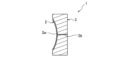
- FIG. 2 is a schematic AA line end view of the ultrasonic sensor of FIG.
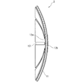
- FIG. 3 is a schematic enlarged sectional view taken along the line AA of the vibration detecting element of the ultrasonic sensor of FIG.
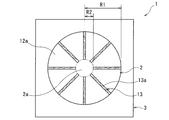
- FIG. 4 is a schematic front view of the ultrasonic sensor of FIG.
- FIG. 5 is a schematic rear view showing a bonded state between the vibration detection element and the support member of the ultrasonic sensor of FIG.
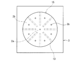
- FIG. 6 is a schematic front view showing the arrangement of the through holes of the supporting member of the ultrasonic sensor of FIG.
- FIG. 1 is a schematic perspective view of an ultrasonic sensor including a vibration detection element according to an embodiment of the present invention.
- FIG. 2 is a schematic AA line end view of the ultrasonic sensor of FIG.
- FIG. 3 is a schematic enlarged sectional view taken along the line AA of the vibration detecting
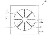
- FIG. 7 is a schematic front view showing an ultrasonic sensor according to an embodiment different from the ultrasonic sensor of FIG.
- FIG. 8 is a schematic front view showing a vibration detecting element of an ultrasonic sensor according to an embodiment different from the ultrasonic sensors of FIGS. 1 and 7.
- FIG. 9 is a schematic front view showing a vibration detecting element of an ultrasonic sensor according to an embodiment different from the ultrasonic sensors of FIGS. 1, 7 and 8.
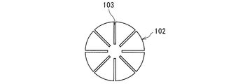
- FIG. 10 is a schematic front view showing the vibration detection element of the ultrasonic sensor according to the comparative embodiment.
- An ultrasonic sensor includes a support member having a curved surface, a film-shaped piezoelectric body provided on the curved surface of the support member, and a pair of electrodes laminated on the front and back of the piezoelectric body.
- a vibration detecting element which is an ultrasonic sensor including at least a part of the vibration detecting element, has a non-vibration detecting section that does not detect vibration, and the non-vibration detecting section is a table of the piezoelectric body or It is a portion where the electrode is not laminated on at least one of the back side and extends inward from the edge of the curved surface of the support member.
- the vibration detecting element has a base portion, and the non-vibration detecting portion may extend radially from the outer peripheral edge of the base portion.
- the piezoelectric body preferably has a slit in the non-vibration detecting portion.
- the vibration detection element may be curved or bent in the non-vibration detection part in a direction perpendicular to the extending direction of the non-vibration detection part.
- the curved surface should be concave.
- a pleats formed by the piezoelectric body may be formed on the non-vibration detection section.
- the support member preferably has at least one through hole.
- the vibration detecting element may be bonded to the supporting member by one or more non-vibration detecting portions.
- An ultrasonic sensor manufacturing method includes a support member having a curved surface, a film-shaped piezoelectric body, and a pair of electrodes laminated on the front and back surfaces of the piezoelectric body, and at least a part of the piezoelectric body.
- a vibration detecting element that does not detect vibration wherein the non-vibration detecting portion uses a vibration detecting element that is a portion in which the electrode is not laminated on at least one of the front and back of the piezoelectric body, The step of laminating the detection element on the curved surface, and the step of laminating the vibration detection element such that the non-vibration detection portion extends inward from the edge of the curved surface of the support member after the laminating step or at the same time as the laminating step. And a step of forming a shape according to the shape of.
- the "front” means the side that receives the vibration
- the "back” means the opposite side.
- the “fold” means a wrinkle formed by overlapping, folding, or the like.
- the ultrasonic sensor can be easily formed into a three-dimensional curved shape.
- the ultrasonic sensor 1 of FIGS. 1 and 2 includes a vibration detection element 2 and a support member 3 that supports the vibration detection element 2 from the back side.
- the ultrasonic sensor 1 is used in an inspection device for ultrasonically inspecting the heat sealability of a food package and the presence or absence of bubbles in a storage battery or a fuel cell.
- the surface on the front side of the vibration detecting element 2 constitutes an ultrasonic receiving surface that faces an ultrasonic transmitter (not shown) with the subject in between.
- the ultrasonic wave transmitting surface of the ultrasonic wave transmitter is formed as a quadratic curve rotating surface, a rotating parabolic surface, or the like so that the ultrasonic wave can be focused toward one point of the subject.
- the vibration detecting element 2 includes a film-shaped piezoelectric body 11 and a pair of electrodes laminated on the front and back sides of the piezoelectric body 11 (the first electrode 12a and the piezoelectric body laminated on the front side surface of the piezoelectric body 11). It has a second electrode 12b) laminated on the backside of the body 11.
- the vibration detecting element 2 has a sheet shape as a whole.
- the piezoelectric material forming the piezoelectric body 11 may be a flexible polymer piezoelectric material.
- the polymeric piezoelectric material include polyvinylidene fluoride (PVDF), vinylidene fluoride-trifluoroethylene copolymer (P (VDF / TrFE)), vinylidene cyanide-vinyl acetate copolymer (P (VDCN / VAc)) and the like. Further, by using these polymeric piezoelectric materials as the porous film, the flexibility is further increased, and the bendability and bendability of the vibration detection element 2 can be enhanced.
- the piezoelectric body 11 for example, polytetrafluoroethylene (PTFE), polypropylene (PP), polyethylene (PE), polyethylene terephthalate (PET), etc., which do not have piezoelectric characteristics, are formed with a large number of flat pores to form a corona discharge.
- PTFE polytetrafluoroethylene
- PP polypropylene
- PE polyethylene
- PET polyethylene terephthalate
- the lower limit of the average thickness of the piezoelectric body 11 is preferably 10 ⁇ m, more preferably 50 ⁇ m.
- the upper limit of the average thickness of the piezoelectric body 11 is preferably 500 ⁇ m, more preferably 200 ⁇ m. If the average thickness of the piezoelectric body 11 is less than the lower limit, the strength of the piezoelectric body 11 may be insufficient. On the other hand, if the average thickness of the piezoelectric body 11 exceeds the upper limit, it may be difficult to form the vibration detection element 2 into a desired curved or bent shape when the vibration detection element 2 is laminated on the support member 3.
- the first electrode 12a and the second electrode 12b are thin films.
- the first electrode 12a and the second electrode 12b are used to detect the potential difference between the front surface and the back surface of the piezoelectric body 11. Therefore, the first electrode 12a and the second electrode 12b are connected to a detection circuit (not shown).
- the material of the first electrode 12a and the second electrode 12b may be any material having conductivity, and examples thereof include metals such as aluminum, copper and nickel, and carbon.
- the method for laminating the first electrode 12a and the second electrode 12b on the piezoelectric body 11 is not particularly limited, and examples thereof include vapor deposition of metal, printing of carbon conductive ink, and coating and drying of silver paste.
- the average thickness of the first electrode 12a and the second electrode 12b may be, for example, 0.1 ⁇ m or more and 30 ⁇ m or less, depending on the stacking method. If the average thickness is less than the lower limit, the strength of the first electrode 12a and the second electrode 12b may be insufficient. On the contrary, when the average thickness exceeds the upper limit, there is a possibility that the followability to the curved surface shape in the state where the vibration detecting element 2 is curved or bent is deteriorated.
- the vibration detecting element 2 has a plurality of belt-shaped low-rigidity portions 13 extending inward from the outer edge thereof.
- the vibration detecting element 2 is smoothly curved or bent in a direction perpendicular to the extending direction of the low-rigidity portion 13 while absorbing the excess portion of the sheet in the plurality of low-rigidity portions 13.
- the vibration detecting element 2 is also curved or bent in the direction along the extending direction of the plurality of low-rigidity portions 13. That is, the vibration detecting element 2 is curved or bent three-dimensionally by the plurality of low-rigidity portions 13.
- the “strip shape” means a shape whose width is smaller than its length.
- the "extending direction of the low-rigidity portion” means a direction perpendicular to the width of the low-rigidity portion at any point.
- the low-rigidity portion 13 is a portion of the vibration detection element 2 having a lower rigidity than the portion where the first electrode 12a and the second electrode 12b are laminated on the piezoelectric body 11.
- the plurality of low-rigidity portions 13 are formed with the outer edge of the vibration detection element 2 as one end in the extending direction.
- the plurality of low-rigidity portions 13 are thin portions in which the first electrode 12a and the second electrode 12b are not laminated on both surfaces of the piezoelectric body 11.
- the vibration detecting element 2 is patterned in the same shape in plan view so that the first electrode 12a and the second electrode 12b face each other in the thickness direction of the piezoelectric body 11.
- the non-patterning regions of the first electrode 12a and the second electrode 12b form the low rigidity portion 13. That is, the piezoelectric body 11 has an exposed region where neither the first electrode 12a nor the second electrode 12b is laminated at a position facing each other in the thickness direction, and this exposed region constitutes the low-rigidity portion 13. ing.
- the ultrasonic sensor 1 has a vibration detection unit in which first electrodes 12a and second electrodes 12b are laminated on both surfaces of a piezoelectric body 11, and a first electrode 12a and second electrodes 12b are laminated on both surfaces of the piezoelectric body 11. And has a non-vibration detection unit that does not detect vibration.
- the vibration detection element 2 has at least a part of the non-vibration detection part that does not detect vibration, and the non-vibration detection part has electrodes laminated on at least one of the front and back of the piezoelectric body 11. Not the part.
- the plurality of low-rigidity portions 13 are non-vibration detecting portions that do not detect vibration.
- the vibration detecting element 2 Since the vibration detecting element 2 has the low-rigidity portion 13, the low-rigidity portion 13 absorbs the excess portion of the sheet (while the excess portion of the sheet due to the bending or bending is overlapped with the low-rigidity portion 13). Can be curved to More specifically, the vibration detecting element 2 in the expanded state has a surplus portion in the seat surface direction with respect to the curved or bent state. This excess portion is likely to be formed as a fold in a curved or bent state. At this time, if the low-rigidity portion 13 does not exist, a plurality of folds are likely to occur randomly (no principle) in the vibration detection portion in which the first electrode 12a and the second electrode 12b are laminated on the piezoelectric body 11.
- the vibration detecting element 2 has the low-rigidity part 13 whose rigidity is smaller than that of the vibration detection part is likely to be selectively folded.
- the vibration detection element 2 since the vibration detection element 2 has the low-rigidity portion 13, it is possible to prevent the low-rigidity portion 13 from forming a fold in the vibration detection portion. Therefore, in the ultrasonic sensor 1, since the vibration detection element 2 has the low-rigidity portion 13, it is possible to suppress a decrease in detection sensitivity due to a fold in the vibration detection portion, and appropriately detect vibration.
- the low-rigidity portions 13 arranged radially are arranged at a uniform pitch in the circumferential direction. By arranging the low-rigidity portions 13 at a uniform pitch, it is possible to form folds of the same degree on all the low-rigidity portions 13.
- the low rigidity portion 13 is the thin portion described above.
- the first electrode 12a and the second electrode 12b are separated by the piezoelectric body 11, and a short circuit between the first electrode 12a and the second electrode 12b can be prevented.
- a slit penetrating in the thickness direction of the vibration detection element instead of the low-rigidity portion 13.
- a cutout 103 that penetrates in the thickness direction of the vibration detection element 102 is provided in place of the low-rigidity portion 13, and the cutout 103 is not overlapped even when both sides of the cutout 103 are not overlapped.
- a conductive member may adhere to the end surface cut by 103, or conductive dust may adhere, resulting in a short circuit between the first electrode and the second electrode.
- the piezoelectric body 11 is provided with a thin portion where the first electrode 12a and the second electrode 12b are not laminated, thereby preventing a short circuit between the first electrode 12a and the second electrode 12b. can do.
- the vibration detecting element 2 has a shape corresponding to the shape of the ultrasonic wave transmitting surface of the ultrasonic wave transmitter described above.
- the vibration detecting element 2 is formed in a concave shape that is depressed on the back side.
- the vibration detecting element 2 has a bowl shape. Since the vibration detecting element 2 has a bowl shape, the ultrasonic sensor 1 can easily and surely detect defects such as adhesion failure and bubbles by ultrasonic waves.
- the vibration detecting element 2 has a base portion 2a in a region within its surface.
- the base 2a has a circular shape in plan view, more specifically, a perfect circular shape in plan view.
- the base portion 2a constitutes a part of a vibration detecting portion in which the first electrode 12a and the second electrode 12b are laminated on the piezoelectric body 11.
- the base portion 2a is located at the center portion (that is, the bottom portion) of the vibration detection element 2.
- the outer peripheral edge of the base portion 2a and the outer peripheral edge of the vibration detecting element 2 are formed in a concentric shape in a plan view.
- the vibration detecting element 2 has a plurality of low-rigidity portions 13 (that is, non-vibration detecting portions) radially extending from the outer peripheral edge of the base portion 2a.
- the plurality of low-rigidity portions 13 extend linearly in the radial direction of the vibration detection element 2.
- the plurality of low-rigidity portions 13 radially extend from the outer peripheral edge of the base portion 2a, so that the plurality of low-rigidity portions 13 extend in the extending direction (in the present embodiment, the diameter of the vibration detection element 2).
- the “circle” includes not only a perfect circle but also an ellipse and an oval.
- the base portion 2a is not limited to a circular shape in plan view, and may be a polygonal shape, a star shape, or the like.
- the base portion 2a is a region that does not absorb the excess portion of the sheet in a curved or bent state, and is formed in a relatively small area of the center portion of the vibration detection element 2 as shown in FIG.
- the lower limit of the ratio of the average radius R2 of the base 2a (the length along the curved or bent surface) to the average radius R1 of the vibration detection element 2 (the length along the curved or bent surface, that is, the average radius in the deployed state) is: 0.1 is preferable and 0.3 is more preferable.
- the upper limit of the ratio is preferably 0.5, more preferably 0.4.
- the ratio is less than the lower limit, the area ratio of the plurality of low-rigidity portions 13 becomes relatively large, which may unnecessarily reduce the area of the vibration detection portion.
- the ratio exceeds the upper limit, the plurality of low-rigidity portions 13 cannot sufficiently absorb the excess portion of the sheet, and there is a possibility that the vibration detection portion may be pleated.
- the plurality of low-rigidity portions 13 are arranged at equal angular intervals from the outer peripheral edge of the base portion 2a. By arranging the plurality of low-rigidity portions 13 at equal angular intervals, the plurality of low-rigidity portions 13 can effectively absorb the excess portion of the sheet, and it is easy to prevent the vibration detection portion from being pleated.
- the low-rigidity portion 13 has a strip shape and has a constant width. Since the low-rigidity portion 13 has a constant width, it is possible to absorb the excess portion of the sheet.
- the average width of the plurality of low-rigidity portions 13 can be set according to the size of the vibration detection element 2, but can be set to, for example, 0.5 mm or more and 3 mm or less.
- the low-rigidity portion 13 has a fold 13a. That is, it is preferable that the non-vibration detecting portion is formed with the pleats 13 a formed of the piezoelectric body 11.
- the folds 13a are formed by overlapping the excess sheet portions when the vibration detecting element 2 is formed into a curved shape from the expanded state.
- the folds 13a are formed in the low-rigidity portion 13, so that the vibration detection element 2 can be easily formed into a desired curved surface shape.
- the ultrasonic sensor 1 is formed with the folds in the low-rigidity portion 13, it becomes easy to keep the front side surface of the vibration detecting section in a desired smooth curved surface shape, and the vibration detecting section detects the vibration. A decrease in sensitivity can be suppressed.
- the support member 3 has an inverted shape of the surface on the back side of the vibration detection element 2 and has a mounting surface 3a on which the vibration detection element 2 is mounted from the back side.
- the mounting surface 3a is a curved surface. That is, the vibration detection element 2 is provided on the curved surface of the support member 3.
- the curved surface is a concave surface.
- the mounting surface 3a is curved three-dimensionally and has a bowl shape in the present embodiment.
- the non-vibration detecting portion extends inward from the edge of the curved surface of the support member 3.
- the support member 3 has a plurality of through holes 3b penetrating in the thickness direction (front and back direction).
- the vibration detection element 2 can be easily formed in a shape along the curved surface shape of the mounting surface 3a.
- the “bowl shape” means a shape that is three-dimensionally concave and has a blunt bottom (rounded or flat bottom).
- the non-vibration detecting section extendends from the edge of the curved surface” means that the end of the non-vibration detecting section is located at the edge of the curved surface, and It includes a structure in which a curved surface region of the support member exists.
- the support member 3 is formed of, for example, a synthetic resin as a main component.
- this synthetic resin include polyethylene terephthalate and polypropylene.
- a "main component” means a component with the largest content in terms of mass.
- the ultrasonic sensor 1 has a plurality of adhesive portions 14 (a plurality of first adhesive portions 14 a and a plurality of second adhesive portions 14 b) that adhere the vibration detection element 2 and the support member 3.
- the plurality of adhesive portions 14 can be formed by, for example, a well-known double-sided tape or adhesive.
- the plurality of first adhesive portions 14a are laminated on the plurality of low-rigidity portions 13. That is, the vibration detecting element 2 is bonded to the support member 3 at the plurality of non-vibration detecting portions. As a result, the vibration detection element 2 is partially bonded to the mounting surface 3a by the plurality of low-rigidity portions 13. In the ultrasonic sensor 1, the resonance frequency of the vibration detection element 2 is affected by the support member 3 because the vibration detection element 2 is partially bonded to the mounting surface 3a by the plurality of low-rigidity portions 13. It is possible to suppress the change.
- the plurality of second adhesive portions 14b are laminated on the outer peripheral edge portion of the vibration detection element 2.
- the plurality of second adhesive portions 14b are laminated on the outer peripheral edge portion of the second electrode 12b (that is, the vibration detection portion).
- the vibration detection element 2 is partially bonded to the mounting surface 3a at the outer peripheral edge portion of the vibration detection element 2 in addition to the plurality of low-rigidity portions 13.
- the resonance frequency of the vibration detection element 2 is affected by the support member 3 because the vibration detection element 2 is partially bonded to the mounting surface 3a at the outer peripheral edge portion of the vibration detection element 2. It is possible to easily suppress the peeling of the vibration detection element 2 from the mounting surface 3a while suppressing such a change.
- the plurality of through holes 3b are provided so as to reach the vibration detection element 2.
- the plurality of through holes 3b are provided so as to reach the vibration detection element 2 at a position not overlapping the plurality of low-rigidity portions 13.
- the ultrasonic sensor 1 can communicate the space on the back side of the vibration detection portion of the vibration detection element 2 with the space on the back side of the support member 3.
- the ultrasonic sensor 1 can suppress the resonance frequency of the vibration detection element 2 from being affected by the sealing with the mounting surface 3a.
- the ultrasonic sensor 1 includes the vibration detection unit in which the plurality of low-rigidity portions 13 that are non-vibration detection units and the first electrode 12a and the second electrode 12b are laminated on both surfaces of the piezoelectric body 11. 15 and.
- the vibration detecting unit 15 has a base portion 2a and a plurality of peripheral edge portions 2b defined by a plurality of low-rigidity portions 13 outside the outer peripheral edge of the base portion 2a.
- the ultrasonic sensor 1 is provided with through holes 3b corresponding to the base portion 2a and the plurality of peripheral portions 2b.
- the through holes 3b are provided in the base portion 2a and the peripheral portions 2b, and preferably, the through holes 3b are provided in a one-to-one correspondence with the base portion 2a and the peripheral portions 2b.
- the ultrasonic sensor 1 can communicate the space on the back side of each section of the vibration detection unit 15 with the space on the back side of the support member 3.
- the ultrasonic sensor 1 can more reliably suppress the resonance frequency of the vibration detection element 2 from being affected by the sealing with the mounting surface 3a.
- the ultrasonic sensor 1 fixes the vibration detection element 2 on the mounting surface 3a while allowing the flat film-shaped (developed state) vibration detection element 2 to follow the curved surface shape of the mounting surface 3a of the support member 3. It is formed by The method of manufacturing the ultrasonic sensor 1 includes a step of stacking the vibration detection element 2 on the mounting surface 3a (that is, a curved surface) of the support member 3 (a stacking step), and vibration detection after or at the same time as the stacking step. And a step (forming step) of forming the element 2 into a shape along the curved surface shape of the mounting surface 3a.
- the vibration detecting element 2 can be formed into a shape along the curved surface shape of the mounting surface 3a by suction from the back side of the supporting member 3.
- the vibration detecting element 2 may be pressed from the front side by a convex member.
- the vibration detecting element 2 is formed in a shape along the curved surface so that the non-vibration detecting portion extends inward from the edge of the curved surface of the support member 3.
- the vibration detecting element 2 is sucked toward the mounting surface 3a side by vacuuming from the plurality of through holes 3b of the supporting member 3.
- a plurality of folds 13a are selectively formed in the plurality of low-rigidity portions 13 of the vibration detecting element 2, whereby the vibration detecting element 2 is formed into a desired curved surface shape while absorbing the excess portion of the sheet.
- the vibration detecting element 2 has a plurality of belt-shaped low-rigidity portions 13 extending inward from the outer edge thereof, and the plurality of low-rigidity portions 13 are arranged in a direction perpendicular to the extending direction of the low-rigidity portions 13. It can be curved or bent. Furthermore, since the vibration detection element 2 has the plurality of belt-shaped low-rigidity portions 13, the vibration-detection element 2 is easily bent or bent in the direction along the extending direction of the low-rigidity portions 13. Therefore, the vibration detecting element 2 can be easily formed into a three-dimensional curved shape.
- the vibration detection element 2 has a plurality of belt-shaped low-rigidity portions 13 extending inward from the outer edge thereof.
- the low-rigidity portion 13 can be curved or bent in a direction perpendicular to the extending direction.
- the vibration detection element 2 since the vibration detection element 2 has the plurality of belt-shaped low-rigidity portions 13, the vibration detection element 2 is curved or bent in a direction along the extending direction of the low-rigidity portions 13. It's easy to do. Therefore, the ultrasonic sensor 1 can easily form the vibration detecting element 2 having a three-dimensional curved shape.
- the ultrasonic wave detecting element 2 is used as a pair with the ultrasonic wave transmitter. It is preferably used as a sensor for detecting sound waves.
- the method of manufacturing the ultrasonic sensor can easily and reliably manufacture the ultrasonic sensor 1 in which the vibration detecting element 2 can be easily formed into a three-dimensional curved shape.
- the ultrasonic sensor 21 of FIG. 7 includes a vibration detection element 22 and a support member 3 that supports the vibration detection element 22 from the back side.
- the vibration detection element 22 has a plurality of belt-shaped low-rigidity portions 23 (that is, non-vibration detection portions) extending inward from the outer edge thereof.
- the low-rigidity portion 23 has a slit 13b. That is, the vibration detecting element 22 has the slit 13b in the non-vibration detecting portion.
- the ultrasonic sensor 21 may have the same configuration as the ultrasonic sensor 1 of FIG. 1 except that the low-rigidity portion 23 has the slit 13b. Therefore, only the slit 13b will be described below.
- the slit 13b extends inward from the outer edge of the vibration detecting element 22.
- the slit 13b extends along the extending direction of the low-rigidity portion 23 at an intermediate position in the width direction of the low-rigidity portion 23 (a position that does not include both ends in the width direction).
- the slits 13b may be provided only in a part of the low-rigidity portions 23, it is preferable that the slits 13b be provided in each low-rigidity portion 23 in a one-to-one correspondence.
- the vibration detection element 22 Since the low-rigidity portion 23 has the slit 13b, the vibration detection element 22 is easily bent or bent by the slit 13b.
- the vibration detecting element 22 since the slit 13b is formed at an intermediate position in the width direction of the low-rigidity portion 23, at least one of the first electrode 12a and the second electrode 12b is provided in a certain range on both sides of the slit 13b. A non-vibration detection part is formed in which one does not exist. Therefore, the vibration detection element 22 easily suppresses a short circuit between the first electrode 12a and the second electrode 12b.
- the vibration detection element 22 since the vibration detection element 22 has the slit 13b in the low-rigidity portion 23, it is easy to bend or bend the vibration detection element 22 with the slit 13b.
- the slit 13b is formed at the intermediate position in the width direction of the low-rigidity portion 23, it is easy to suppress a short circuit between the first electrode 12a and the second electrode 12b.
- the base portion of the vibration detecting element does not necessarily have to be a perfect circle shape in plan view.
- the base 32a may have an oval shape.
- the plurality of low-rigidity portions 33 may extend radially only from the circumferential portion of the outer peripheral edge of the base portion 32a.
- the vibration detection element may have only one low-rigidity portion extending inward from the outer edge thereof.
- the vibration detecting element 42 of FIG. 9 has only one low-rigidity portion 43 extending inward from its outer edge.
- the low-rigidity portion 43 is formed in a spiral shape from the outer edge of the vibration detection element 42 toward the inside. That is, the low-rigidity portion 43 does not extend radially from the outer peripheral edge of the base portion that is circular in plan view. Even with this configuration, the vibration detection element can bend or bend in the low-rigidity portion 43 in the direction perpendicular to the extending direction of the low-rigidity portion 43.
- the curved surface shape of the vibration detecting element can be set according to the application, and the vibration detecting element does not necessarily have to be bowl-shaped.
- the vibration detection element may be configured in a dome shape or the like that is raised on the front side.
- the one or more low-rigidity portions may be composed of a thin portion in which electrodes are laminated only on one surface of the piezoelectric body.
- the difference in rigidity between the low-rigidity portion and the other portion (vibration detection portion) is large. Therefore, it is more preferable that the low-rigidity portion is a thin portion in which electrodes are not laminated on both surfaces of the piezoelectric body.
- the pair of electrodes may not be patterned in the same shape in plan view.
- a region where at least one electrode is not laminated on the piezoelectric body can be configured as a thin portion.
- a slit may be formed in the low rigidity portion. Further, the slit may be formed in an inner region apart from the outer edge of the vibration detecting element. Further, in the vibration detecting element, two or more slits may be formed for one low rigidity portion.
- the vibration detecting element may be provided with a low-rigidity portion between the base portion and the plurality of peripheral portions.
- a thin portion where at least one electrode is not laminated on the piezoelectric body may be formed between the base portion and the plurality of peripheral portions.
- the width of the one or more low-rigidity portions may not be constant along the extending direction.
- the width of these low-rigidity portions may be gradually reduced toward the outer side in the radial direction, may be gradually increased, and the width may be gradually increased. Both the gradually decreasing area and the gradually increasing area may be included.
- the ultrasonic sensor does not necessarily need to have pleats formed on the one or more low-rigidity portions as long as the curved shape of the vibration detecting element can be appropriately maintained.
- the ultrasonic sensor does not necessarily have to have the above-mentioned supporting member as long as the curved surface shape of the vibration detecting element can be maintained.
- the vibration detection element may be partially bonded to the mounting surface only at the one or more low-rigidity portions. Further, in the case where the ultrasonic sensor has this supporting member, the vibration detecting element and the supporting member can be adhered and fixed at an arbitrary laminated region of the electrode if the detection accuracy is not insufficient. ..
- the ultrasonic sensor may have a structure in which a plurality of vibration detecting elements are laminated on a supporting member.
- the ultrasonic sensor according to one aspect of the present invention can be easily formed into a three-dimensional curved shape, it is preferably used as an ultrasonic detection sensor.
Landscapes
- Physics & Mathematics (AREA)
- Engineering & Computer Science (AREA)
- Acoustics & Sound (AREA)
- Signal Processing (AREA)
- Health & Medical Sciences (AREA)
- Life Sciences & Earth Sciences (AREA)
- Chemical & Material Sciences (AREA)
- Analytical Chemistry (AREA)
- Biochemistry (AREA)
- General Health & Medical Sciences (AREA)
- General Physics & Mathematics (AREA)
- Immunology (AREA)
- Pathology (AREA)
- Transducers For Ultrasonic Waves (AREA)
- Investigating Or Analyzing Materials By The Use Of Ultrasonic Waves (AREA)
Abstract
本発明は、3次元湾曲形状を容易に形成することが可能な超音波センサの提供を課題とする。本発明の一態様に係る超音波センサ1は、曲面を有する支持部材3と、支持部材3の曲面に設けられる、フィルム状の圧電体及びこの圧電体の表裏に積層される一対の電極から構成される振動検出素子2とを備え、振動検出素子2の少なくとも一部に、振動を検出しない非振動検出部を有し、非振動検出部は、圧電体の表または裏の少なくとも一方に電極12aが積層されていない部分であり、支持部材3の曲面の縁から内側に延在している。
Description
本発明は、超音波センサ及び超音波センサの製造方法に関する。
例えば食品パッケージのヒートシール性、蓄電池や燃料電池等の中の気泡の有無等を検査するために超音波センサが用いられる。この超音波センサは、被検体を挟んで超音波発信器と対向して設けられる。この超音波センサは、超音波発信器から発信され、被検体を透過した超音波を検出することでヒートシールの接着状態等を検査可能に構成される。
この超音波センサは、圧電素子から構成され、被検体を挟んで超音波発信器と対向する超音波受信面を有している。この超音波受信面は、例えば被検体に焦点が位置する凹曲面形状を有している(特開2013-127400号公報参照)。
この超音波センサは、例えば一方向に弓なりに凹状に湾曲した背面付加材の上面に圧電素子を積層し、この圧電素子の上方から背面付加材の上面の反転形状を有する加圧板を押圧することで形成される(特開2010-258602号公報参照)。また、この圧電素子としては、チタン酸ジルコン酸鉛(PZT)等から構成される比較的高価な無機圧電体の両面に一対の電極を積層したものが用いられている。
一方、被検体のヒートシール性等を高精度で検査するためには、超音波発信器の超音波発信面及び超音波センサの超音波受信面をそれぞれ焦点位置が一致する3次元湾曲形状(例えば椀状)に形成することが望まれる。
しかしながら、前記従来の超音波センサを3次元湾曲形状に形成すると、超音波を検出する領域に皺が生じたりすることで適切な検査を行えないおそれがある。
本発明は、このような事情に基づいてなされたものであり、本発明の課題は、3次元湾曲形状を容易に形成することが可能な超音波センサを提供することにある。
前記課題を解決するためになされた本発明の一態様に係る超音波センサは、曲面を有する支持部材と、前記支持部材の曲面に設けられる、フィルム状の圧電体及びこの圧電体の表裏に積層される一対の電極から構成される振動検出素子と、を備えた超音波センサであって、前記振動検出素子の少なくとも一部に、振動を検出しない非振動検出部を有し、前記非振動検出部は、前記圧電体の表または裏の少なくとも一方に前記電極が積層されていない部分であり、前記支持部材の曲面の縁から内側に延在する。
本発明の一態様に係る超音波センサは、曲面を有する支持部材と、前記支持部材の曲面に設けられる、フィルム状の圧電体及びこの圧電体の表裏に積層される一対の電極から構成される振動検出素子と、を備えた超音波センサであって、前記振動検出素子の少なくとも一部に、振動を検出しない非振動検出部を有し、前記非振動検出部は、前記圧電体の表または裏の少なくとも一方に前記電極が積層されていない部分であり、前記支持部材の曲面の縁から内側に延在する。
前記振動検出素子は基部を有し、前記非振動検出部はこの基部の外周縁から放射状に延びているとよい。
前記圧電体は前記非振動検出部にスリットを有するとよい。
前記振動検出素子は、前記非振動検出部において、当該非振動検出部の延在方向と垂直な方向に湾曲又は屈曲しているとよい。
前記曲面が凹面であるとよい。
前記非振動検出部に前記圧電体によるひだが形成されるとよい。
前記支持部材は少なくとも1つの貫通孔を有するとよい。
前記振動検出素子は1又は複数の前記非振動検出部で前記支持部材と接着されているとよい。
本発明の他の一態様に係る超音波センサの製造方法は、曲面を有する支持部材と、フィルム状の圧電体及びこの圧電体の表裏に積層される一対の電極から構成され、少なくとも一部に、振動を検出しない非振動検出部を有し、前記非振動検出部は、前記圧電体の表または裏の少なくとも一方に前記電極が積層されていない部分である振動検出素子とを用い、前記振動検出素子を前記曲面に積層する工程と、前記積層工程後又は前記積層工程と同時に、前記非振動検出部が前記支持部材の曲面の縁から内側に延在するように前記振動検出素子を前記曲面の形状に沿った形状に形成する工程とを備える。
なお、本発明において、「表」とは振動を受信する側をいい、「裏」とはその反対側をいう。「ひだ」とは、重なり合い、折り返し等によって形成された皺を意味する。
当該超音波センサは、3次元湾曲形状に容易に形成することができる。
以下、適宜図面を参照しつつ、本発明の実施の形態を詳説する。
[第一実施形態]
<超音波センサ>
図1及び図2の超音波センサ1は、振動検出素子2と、振動検出素子2を裏側から支持する支持部材3とを備える。当該超音波センサ1は、食品パッケージのヒートシール性、蓄電池や燃料電池の中の気泡の有無等を超音波によって検査するための検査装置に用いられる。当該超音波センサ1は、振動検出素子2の表側の面が、被検体を挟んで超音波発信器(不図示)と対向する超音波受信面を構成する。前記超音波発信器の超音波発信面は、被検体の一点に向けて超音波を集束できるよう二次曲線回転面、回転放物面等に形成されている。
<超音波センサ>
図1及び図2の超音波センサ1は、振動検出素子2と、振動検出素子2を裏側から支持する支持部材3とを備える。当該超音波センサ1は、食品パッケージのヒートシール性、蓄電池や燃料電池の中の気泡の有無等を超音波によって検査するための検査装置に用いられる。当該超音波センサ1は、振動検出素子2の表側の面が、被検体を挟んで超音波発信器(不図示)と対向する超音波受信面を構成する。前記超音波発信器の超音波発信面は、被検体の一点に向けて超音波を集束できるよう二次曲線回転面、回転放物面等に形成されている。
(振動検出素子)
図3に示すように、振動検出素子2は、フィルム状の圧電体11及び圧電体11の表裏に積層される一対の電極(圧電体11の表側の面に積層される第1電極12a及び圧電体11の裏側の面に積層される第2電極12b)を有する。振動検出素子2は、全体としてシート状である。
図3に示すように、振動検出素子2は、フィルム状の圧電体11及び圧電体11の表裏に積層される一対の電極(圧電体11の表側の面に積層される第1電極12a及び圧電体11の裏側の面に積層される第2電極12b)を有する。振動検出素子2は、全体としてシート状である。
圧電体11を形成する圧電材料としては、可撓性を有する高分子圧電材料が挙げられる。前記高分子圧電材料としては、例えばポリフッ化ビニリデン(PVDF)、フッ化ビニリデン-3フッ化エチレン共重合体(P(VDF/TrFE))、シアン化ビニリデン-酢酸ビニル共重合体(P(VDCN/VAc))等が挙げられる。また、これらの高分子圧電材料を多孔性フィルムとすることによって、より可撓性が大きくなり、振動検出素子2の湾曲性及び屈曲性を高めることができる。
また、圧電体11としては、圧電特性を有しない例えばポリテトラフルオロエチレン(PTFE)、ポリプロピレン(PP)、ポリエチレン(PE)、ポリエチレンテレフタレート(PET)等に多数の扁平な気孔を形成し、コロナ放電等によって扁平な気孔の対向面を分極して帯電させることによって圧電特性を付与したものを使用することもできる。
圧電体11の平均厚さの下限としては、10μmが好ましく、50μmがより好ましい。一方、圧電体11の平均厚さの上限としては、500μmが好ましく、200μmがより好ましい。圧電体11の平均厚さが前記下限に満たないと、圧電体11の強度が不十分となるおそれがある。逆に、圧電体11の平均厚さが前記上限を超えると、振動検出素子2を支持部材3に積層する際に、所望の湾曲又は屈曲形状に形成し難くなるおそれがある。
第1電極12a及び第2電極12bは薄膜状である。第1電極12a及び第2電極12bは圧電体11の表裏の電位差を検出するために用いられる。このため、第1電極12a及び第2電極12bは、不図示の検出回路に接続される。
第1電極12a及び第2電極12bの材質としては、導電性を有するものであればよく、例えばアルミニウム、銅、ニッケル等の金属や、カーボン等が挙げられる。
第1電極12a及び第2電極12bの圧電体11への積層方法としては、特に限定されず、例えば金属の蒸着、カーボン導電インクの印刷、銀ペーストの塗布乾燥等が挙げられる。
第1電極12a及び第2電極12bの平均厚さとしては、積層方法にもよるが、例えば0.1μm以上30μm以下とすることができる。前記平均厚さが前記下限に満たないと、第1電極12a及び第2電極12bの強度が不十分となるおそれがある。逆に、前記平均厚さが前記上限を超えると、振動検出素子2を湾曲又は屈曲した状態での曲面形状への追従性が低下するおそれがある。
振動検出素子2は、その外縁から内側に延びる複数の帯状の低剛性部13を有する。振動検出素子2は、複数の低剛性部13においてシートの余剰部分を吸収しながら滑らかに低剛性部13の延在方向と垂直な方向に湾曲又は屈曲している。また、振動検出素子2は、複数の低剛性部13の延在方向に沿う方向でも湾曲又は屈曲している。つまり、振動検出素子2は、複数の低剛性部13で3次元的に湾曲又は屈曲している。なお、「帯状」とは、長さに対して幅が小さい形状をいう。また、「低剛性部の延在方向」とは、低剛性部の任意の点における幅と垂直な方向をいう。
低剛性部13は、振動検出素子2において、圧電体11に第1電極12a及び第2電極12bが積層されている部分よりも剛性の小さい部分である。複数の低剛性部13は、振動検出素子2の外縁をその延在方向の一端として形成されている。複数の低剛性部13は、圧電体11の両面に第1電極12a及び第2電極12bが積層されていない肉薄部である。振動検出素子2は、第1電極12a及び第2電極12bが圧電体11の厚さ方向に対向するよう平面視略同一形状にパターニングされている。振動検出素子2は、第1電極12a及び第2電極12bの非パターニング領域が低剛性部13を構成している。つまり、圧電体11は、厚さ方向に対向する位置に第1電極12a及び第2電極12bがいずれも積層されていない露出領域を有しており、この露出領域が低剛性部13を構成している。当該超音波センサ1は、圧電体11の両面に第1電極12a及び第2電極12bが積層された振動検出部と、圧電体11の両面に第1電極12a及び第2電極12bが積層されておらず、振動を検出しない非振動検出部とを有する。つまり、振動検出素子2は、少なくとも一部に、振動を検出しない前記非振動検出部を有しており、この非振動検出部は、圧電体11の表または裏の少なくとも一方に電極が積層されていない部分である。当該超音波センサ1において、複数の低剛性部13は、振動を検出しない非振動検出部である。
当該振動検出素子2は、低剛性部13を有することによって、シートの余剰部分を低剛性部13で吸収しつつ(湾曲又は屈曲に伴うシートの余剰部分を低剛性部13で重なり合わせながら)容易に湾曲することができる。詳しく説明すると、展開状態の振動検出素子2は、湾曲又は屈曲した状態に対してシート面方向において余剰部分を有している。この余剰部分は、湾曲又は屈曲した状態でひだとして形成されやすい。この際、低剛性部13が存在しないと、圧電体11に第1電極12a及び第2電極12bが積層された前記振動検出部にランダム(無原則)で複数のひだが生じやすい。これに対し、振動検出素子2が低剛性部13を有する場合、前記振動検出部よりも剛性が小さい低剛性部13に選択的にひだが生じやすくなる。換言すると、振動検出素子2が低剛性部13を有することで、この低剛性部13が前記振動検出部にひだが発生することを抑制する。従って、当該超音波センサ1は、振動検出素子2が低剛性部13を有することで、前記振動検出部にひだが生じることに起因する検出感度の低下を抑制し、振動を適切に検出することができる。前記振動検出部にひだが発生することを更に抑制するには、放射状に配置された低剛性部13が周回方向に均一のピッチで配置されるのが好ましい。均一なピッチで低剛性部13が配置されることで、全ての低剛性部13に同程度のひだを形成することができる。
また、当該振動検出素子2は、低剛性部13が前述の肉薄部である。これにより、第1電極12a及び第2電極12bは圧電体11によって分離され、第1電極12a及び第2電極12b間の短絡を防止することができる。詳しく説明すると、例えば第1電極12a及び第2電極12bの両方が形成されているところ(つまり、前述の振動検出部)に低剛性部13に代えて振動検出素子の厚さ方向を貫通するスリットを設け、このスリットを挟む両側の部分を重ね合わせることで湾曲又は屈曲形状を形成した場合、重ね合わせた部分で第1電極と第2電極が接続され、短絡を生じる。また、図10に示すように、低剛性部13に代えて振動検出素子102の厚さ方向に貫通する切欠き103を設け、切欠き103を挟む両側の部分を重ね合わせない場合でも、切欠き103による切断端面に導電性の部材が付着したり、導電性のゴミが付着することで第1電極及び第2電極間が短絡するおそれがある。これに対し、当該振動検出素子2は、圧電体11に第1電極12a及び第2電極12bが積層されていない肉薄部を設けることで、第1電極12a及び第2電極12b間の短絡を防止することができる。
振動検出素子2は、前述の超音波発信器の超音波発信面の形状に対応した形状を有する。振動検出素子2は、裏側に陥没した凹状に形成される。本実施形態において、振動検出素子2は椀状である。当該超音波センサ1は、振動検出素子2が椀状であることによって、接着不良や気泡等の不具合を超音波によって容易かつ確実に検出することができる。
図4に示すように、振動検出素子2は、その面内の領域に基部2aを有する。基部2aは、平面視円形、より詳しくは平面視真円状である。基部2aは、圧電体11に第1電極12a及び第2電極12bが積層された振動検出部の一部分を構成する。基部2aは、振動検出素子2の中心部(つまり底部)に位置する。基部2aの外周縁と振動検出素子2の外周縁とは平面視同心円状に形成されている。振動検出素子2は、複数の低剛性部13(すなわち非振動検出部)が基部2aの外周縁から放射状に延びている。複数の低剛性部13は振動検出素子2の径方向に直線状に延びている。当該振動検出素子2は、複数の低剛性部13が基部2aの外周縁から放射状に延びていることによって、複数の低剛性部13の延在方向(本実施形態では当該振動検出素子2の径方向)に亘ってシートの余剰部分を吸収しつつ、複数の低剛性部13の延在方向と垂直な方向に容易に湾曲又は屈曲することができる。なお、「円形」とは、真円形のみならず、楕円形及び長円形を含む。また、基部2aは平面視円形に限らず、多角形、星型等であってもよい。
基部2aは、湾曲又は屈曲状態でシートの余剰部分を吸収しない領域であり、図4に示すように、振動検出素子2の中心部の比較的小さい範囲に形成される。振動検出素子2の平均半径R1(湾曲又は屈曲面に沿う長さ。すなわち、展開状態における平均半径)に対する基部2aの平均半径R2(湾曲又は屈曲面に沿う長さ)の比の下限としては、0.1が好ましく、0.3がより好ましい。一方、前記比の上限としては、0.5が好ましく、0.4がより好ましい。前記比が前記下限に満たないと、複数の低剛性部13の面積割合が相対的に大きくなることで、振動検出部の面積が不必要に小さくなるおそれがある。逆に、前記比が前記上限を超えると、複数の低剛性部13によってシートの余剰部分を十分に吸収することができず、振動検出部にひだが生じるおそれがある。
複数の低剛性部13は、基部2aの外周縁から等角度間隔で配置されることが好ましい。複数の低剛性部13が等角度間隔で配置されることによって、複数の低剛性部13によってシートの余剰部分を効果的に吸収し、振動検出部にひだが生じることを防止しやすい。
前述のように、低剛性部13は帯状であり、一定の幅を有する。低剛性部13は一定の幅を有することで、シートの余剰部分を吸収することができる。複数の低剛性部13の平均幅としては、振動検出素子2のサイズに対応して設定可能であるが、例えば0.5mm以上3mm以下とすることができる。
図4に示すように、低剛性部13にはひだ13aが形成されていることが好ましい。つまり、前記非振動検出部には、圧電体11によるひだ13aが形成されることが好ましい。ひだ13aは、振動検出素子2を展開状態から曲面形状に形成する際に、余剰なシート部分が重なり合うこと等によって形成される。当該超音波センサ1は、低剛性部13にひだ13aが形成されることで、振動検出素子2を所望の曲面形状に形成しやすい。また、当該超音波センサ1は、低剛性部13にひだが形成されることで、前記振動検出部の表側の面を平滑な所望の曲面形状に保つことが容易となり、前記振動検出部の検出感度の低下を抑制することができる。
(支持部材)
支持部材3は、図2に示すように、振動検出素子2の裏側の面の反転形状を有し、振動検出素子2が裏側から載置される載置面3aを有する。載置面3aは曲面である。つまり、振動検出素子2は支持部材3の前記曲面に設けられている。前記曲面は、凹面である。載置面3aは、3次元に湾曲しており、本実施形態では椀状である。前記非振動検出部は、支持部材3の前記曲面の縁から内側に延在している。また、支持部材3は厚さ方向(表裏方向)に貫通する複数の貫通孔3bを有する。当該超音波センサ1は、支持部材3を備えることによって、振動検出素子2を載置面3aの曲面形状に沿った形状に容易に形成することができる。なお、「椀状」とは、3次元で凹状に形成され、底点が尖っていない(底点が丸められた又は平坦な)形状をいう。また、非振動検出部が「曲面の縁から延在する」とは、非振動検出部の端部が曲面の縁に位置する構成の他、非振動検出部の端部と曲面の縁との間に支持部材の曲面領域が存在する構成を含む。
支持部材3は、図2に示すように、振動検出素子2の裏側の面の反転形状を有し、振動検出素子2が裏側から載置される載置面3aを有する。載置面3aは曲面である。つまり、振動検出素子2は支持部材3の前記曲面に設けられている。前記曲面は、凹面である。載置面3aは、3次元に湾曲しており、本実施形態では椀状である。前記非振動検出部は、支持部材3の前記曲面の縁から内側に延在している。また、支持部材3は厚さ方向(表裏方向)に貫通する複数の貫通孔3bを有する。当該超音波センサ1は、支持部材3を備えることによって、振動検出素子2を載置面3aの曲面形状に沿った形状に容易に形成することができる。なお、「椀状」とは、3次元で凹状に形成され、底点が尖っていない(底点が丸められた又は平坦な)形状をいう。また、非振動検出部が「曲面の縁から延在する」とは、非振動検出部の端部が曲面の縁に位置する構成の他、非振動検出部の端部と曲面の縁との間に支持部材の曲面領域が存在する構成を含む。
支持部材3は、例えば合成樹脂を主成分として形成される。この合成樹脂としては、例えばポリエチレンテレフタレート、ポリプロピレン等が挙げられる。なお、「主成分」とは、質量換算で最も含有量の大きい成分をいう。
図5に示すように、当該超音波センサ1は、振動検出素子2及び支持部材3を接着する複数の接着部14(複数の第1接着部14a及び複数の第2接着部14b)を有する。複数の接着部14は、例えば公知の両面テープや接着剤によって形成することができる。
複数の第1接着部14aは、複数の低剛性部13に積層されている。つまり、振動検出素子2は、複数の前記非振動検出部で支持部材3と接着されている。これにより、振動検出素子2は、複数の低剛性部13で載置面3aと部分的に接着されている。当該超音波センサ1は、振動検出素子2が複数の低剛性部13で載置面3aと部分的に接着されていることによって、振動検出素子2の共振周波数が支持部材3の影響を受けて変化することを抑制することができる。
複数の第2接着部14bは、振動検出素子2の外周縁部に積層されている。本実施形態では、複数の第2接着部14bは、第2電極12b(つまり振動検出部)の外周縁部に積層されている。これにより、振動検出素子2は、複数の低剛性部13に加え、振動検出素子2の外周縁部でも載置面3aと部分的に接着されている。当該超音波センサ1は、振動検出素子2が振動検出素子2の外周縁部で載置面3aと部分的に接着されることによって、振動検出素子2の共振周波数が支持部材3の影響を受けて変化することを抑制しつつ、振動検出素子2の載置面3aからの剥離を容易に抑制することができる。
複数の貫通孔3bは、振動検出素子2に至るよう設けられている。特に、本実施形態では、図5に示すように、複数の貫通孔3bは、複数の低剛性部13と重ならない位置で振動検出素子2に至るよう設けられている。これにより、当該超音波センサ1は、振動検出素子2の前記振動検出部の裏側の空間を支持部材3の裏側の空間に連通することができる。その結果、当該超音波センサ1は、振動検出素子2の共振周波数が載置面3aとの密閉によって影響を受けることを抑制することができる。
図6を参照して、複数の貫通孔3bの配置について詳説する。まず、前述のように、当該超音波センサ1は、非振動検出部である複数の低剛性部13と、圧電体11の両面に第1電極12a及び第2電極12bが積層された振動検出部15とを有している。この振動検出部15は、基部2aと、基部2aの外周縁の外側で複数の低剛性部13によって区画される複数の周縁部2bとを有している。当該超音波センサ1は、基部2a及び複数の周縁部2bに対応して貫通孔3bが設けられている。詳しくは、基部2a及び各周縁部2bに対して貫通孔3bが設けられており、好ましくは基部2a及び各周縁部2bに対して1対1対応で貫通孔3bが設けられている。これにより、当該超音波センサ1は、振動検出部15の各区画の裏側の空間を支持部材3の裏側の空間に連通することができる。その結果、当該超音波センサ1は、振動検出素子2の共振周波数が載置面3aとの密閉によって影響を受けることをより確実に抑制することができる。
<超音波センサの製造方法>
当該超音波センサ1は、平膜状(展開状態)の振動検出素子2を支持部材3の載置面3aの曲面形状に追従させつつ、この振動検出素子2を載置面3a上に固定することで形成される。当該超音波センサ1の製造方法は、振動検出素子2を支持部材3の載置面3a(すなわち曲面)に積層する工程(積層工程)と、この積層工程後又はこの積層工程と同時に、振動検出素子2を載置面3aの曲面形状に沿った形状に形成する工程(形成工程)とを備える。前記形成工程では、支持部材3の裏側からの吸引により振動検出素子2を載置面3aの曲面形状に沿った形状に形成することができる。また、前記形成工程では、支持部材3の裏側からの吸引に代えて、振動検出素子2を表側から凸部材で押さえ付けてもよい。
当該超音波センサ1は、平膜状(展開状態)の振動検出素子2を支持部材3の載置面3aの曲面形状に追従させつつ、この振動検出素子2を載置面3a上に固定することで形成される。当該超音波センサ1の製造方法は、振動検出素子2を支持部材3の載置面3a(すなわち曲面)に積層する工程(積層工程)と、この積層工程後又はこの積層工程と同時に、振動検出素子2を載置面3aの曲面形状に沿った形状に形成する工程(形成工程)とを備える。前記形成工程では、支持部材3の裏側からの吸引により振動検出素子2を載置面3aの曲面形状に沿った形状に形成することができる。また、前記形成工程では、支持部材3の裏側からの吸引に代えて、振動検出素子2を表側から凸部材で押さえ付けてもよい。
前記形成工程では、前記非振動検出部が支持部材3の前記曲面の縁から内側に延在するように振動検出素子2を前記曲面の形状に沿った形状に形成する。前記形成工程では、例えば支持部材3の複数の貫通孔3bからの真空引きにより振動検出素子2を載置面3a側に吸引する。この際、振動検出素子2の複数の低剛性部13に選択的に複数のひだ13aが形成され、これによりシートの余剰な部分を吸収しつつ振動検出素子2を所望の曲面形状に形成することができる。
<利点>
当該振動検出素子2は、その外縁から内側に延びる複数の帯状の低剛性部13を有しており、複数の低剛性部13で、これらの低剛性部13の延在方向と垂直な方向に湾曲又は屈曲することができる。さらに、当該振動検出素子2は、複数の帯状の低剛性部13を有することで、これらの低剛性部13の延在方向に沿う方向にも湾曲又は屈曲しやすい。そのため、当該振動検出素子2は、3次元湾曲形状に容易に形成することができる。
当該振動検出素子2は、その外縁から内側に延びる複数の帯状の低剛性部13を有しており、複数の低剛性部13で、これらの低剛性部13の延在方向と垂直な方向に湾曲又は屈曲することができる。さらに、当該振動検出素子2は、複数の帯状の低剛性部13を有することで、これらの低剛性部13の延在方向に沿う方向にも湾曲又は屈曲しやすい。そのため、当該振動検出素子2は、3次元湾曲形状に容易に形成することができる。
当該超音波センサ1は、振動検出素子2が、その外縁から内側に延びる複数の帯状の低剛性部13を有しているので、振動検出素子2を、複数の低剛性部13で、これらの低剛性部13の延在方向と垂直な方向に湾曲又は屈曲することができる。さらに、当該超音波センサ1は、振動検出素子2が複数の帯状の低剛性部13を有することで、振動検出素子2をこれらの低剛性部13の延在方向に沿う方向にも湾曲又は屈曲しやすい。そのため、当該超音波センサ1は、3次元湾曲形状の振動検出素子2を容易に形成することができる。
当該超音波センサ1は、振動検出素子2を超音波発信器の超音波発信面に対応する所望の3次元湾曲形状に形成することが容易であるので、超音波発信器と対として用いられる超音波検出用のセンサとして好適に用いられる。
当該超音波センサの製造方法は、振動検出素子2を3次元湾曲形状に容易に形成可能な当該超音波センサ1を容易かつ確実に製造することができる。
[第二実施形態]
図7の超音波センサ21は、振動検出素子22と、振動検出素子22を裏側から支持する支持部材3とを備える。振動検出素子22は、その外縁から内側に延びる複数の帯状の低剛性部23(すなわち非振動検出部)を有する。低剛性部23はスリット13bを有する。つまり、振動検出素子22は、前記非振動検出部にスリット13bを有する。当該超音波センサ21は、低剛性部23がスリット13bを有する以外、図1の超音波センサ1と同様の構成とすることができる。そのため、以下ではスリット13bについてのみ説明する。
図7の超音波センサ21は、振動検出素子22と、振動検出素子22を裏側から支持する支持部材3とを備える。振動検出素子22は、その外縁から内側に延びる複数の帯状の低剛性部23(すなわち非振動検出部)を有する。低剛性部23はスリット13bを有する。つまり、振動検出素子22は、前記非振動検出部にスリット13bを有する。当該超音波センサ21は、低剛性部23がスリット13bを有する以外、図1の超音波センサ1と同様の構成とすることができる。そのため、以下ではスリット13bについてのみ説明する。
スリット13bは、振動検出素子22の外縁から内側に延びている。スリット13bは、低剛性部23の幅方向の中間位置(幅方向の両端を含まない位置)で低剛性部23の延在方向に沿って延びている。スリット13bは、一部の低剛性部23にのみ設けられてもよいが、各低剛性部23に例えば1対1対応で設けられることが好ましい。
<利点>
当該振動検出素子22は、低剛性部23がスリット13bを有するので、このスリット13bで湾曲又は屈曲させやすい。当該振動検出素子22は、スリット13bが低剛性部23の幅方向の中間位置に形成されているので、スリット13bを挟む両側の一定範囲には少なくとも第1電極12a及び第2電極12bのいずれか一方が存在しない非振動検出部が形成される。そのため、当該振動検出素子22は、第1電極12a及び第2電極12b間の短絡を抑制しやすい。
当該振動検出素子22は、低剛性部23がスリット13bを有するので、このスリット13bで湾曲又は屈曲させやすい。当該振動検出素子22は、スリット13bが低剛性部23の幅方向の中間位置に形成されているので、スリット13bを挟む両側の一定範囲には少なくとも第1電極12a及び第2電極12bのいずれか一方が存在しない非振動検出部が形成される。そのため、当該振動検出素子22は、第1電極12a及び第2電極12b間の短絡を抑制しやすい。
当該超音波センサ21は、振動検出素子22が低剛性部23にスリット13bを有するので、振動検出素子22をこのスリット13bで湾曲又は屈曲させやすい。当該超音波センサ21は、スリット13bが低剛性部23の幅方向の中間位置に形成されているので、第1電極12a及び第2電極12b間の短絡を抑制しやすい。
[その他の実施形態]
前記実施形態は、本発明の構成を限定するものではない。従って、前記実施形態は、本明細書の記載及び技術常識に基づいて前記実施形態各部の構成要素の省略、置換又は追加が可能であり、それらは全て本発明の範囲に属するものと解釈されるべきである。
前記実施形態は、本発明の構成を限定するものではない。従って、前記実施形態は、本明細書の記載及び技術常識に基づいて前記実施形態各部の構成要素の省略、置換又は追加が可能であり、それらは全て本発明の範囲に属するものと解釈されるべきである。
例えば当該振動検出素子は、基部が平面視円形である場合でも、この基部は必ずしも平面視真円状でなくてもよい。例えば図8に示すように、当該超音波センサは、振動検出素子32が椀状である場合、基部32aは長円状であってもよい。またこの場合、複数の低剛性部33は、基部32aの外周縁の円周部分のみから放射状に延びていてもよい。
当該振動検出素子は、その外縁から内側に延びる前記低剛性部を1つのみ有していてもよい。例えば図9の振動検出素子42は、その外縁から内側に延びる1つの低剛性部43のみを有している。この低剛性部43は、振動検出素子42の外縁から内側に向けて渦巻き状に形成されている。つまり、この低剛性部43は、平面視円形の基部の外周縁から放射状に延びていない。当該振動検出素子は、この構成によっても、低剛性部43で、この低剛性部43の延在方向と垂直な方向に湾曲又は屈曲することができる。
当該超音波センサにおいて、振動検出素子の曲面形状は用途に応じて設定可能であり、振動検出素子は必ずしも椀状でなくてもよい。例えば振動検出素子は、表側に隆起したドーム状等に構成されてもよい。
前記1又は複数の低剛性部は、圧電体の一方の面にのみ電極が積層された肉薄部から構成されてもよい。但し、1又は複数の低剛性部に選択的にひだを形成する観点からは、低剛性部とその他の部分(振動検出部)とで剛性の差が大きい方が好ましい。そのため、低剛性部は、圧電体の両面に電極が積層されていない肉薄部であることがより好ましい。
当該振動検出素子は、前記一対の電極が平面視同一形状でパターニングされていなくてもよい。この場合、少なくとも一方の電極が圧電体に積層されていない領域を肉薄部として構成することができる。
当該振動検出素子は、例えば図8及び図9の構成において、低剛性部にスリットが形成されてもよい。また、前記スリットは、当該振動検出素子の外縁から離れた内側の領域に形成されてもよい。さらに、当該振動検出素子は、1つの低剛性部に対して2以上のスリットが形成されてもよい。
当該振動検出素子は、前記基部と複数の周縁部との間に低剛性部を設けてもよい。換言すると、前記基部と複数の周縁部との間に、圧電体に少なくとも一方の電極が積層されていない肉薄部を形成してもよい。この構成によると、複数の振動検出部を低剛性部で分割したアレイ状のセンサを形成することができる。
前記1又は複数の低剛性部は、延在方向に沿って幅が一定でなくてもよい。例えば当該振動検出素子が放射状に配設される複数の低剛性部を有する場合、これらの低剛性部は、放射方向外側に向けて幅が漸減してもよく、漸増してもよく、幅が漸減する領域と幅が漸増領域とを共に有していてもよい。
当該超音波センサは、前記振動検出素子の曲面形状が適切に維持可能な場合であれば、前記1又は複数の低剛性部には必ずしもひだが形成されていなくてもよい。
当該超音波センサは、前記振動検出素子の曲面形状が維持できる限り、必ずしも前述の支持部材を有していなくてもよい。
当該超音波センサは、前記支持部材を有する場合、前記振動検出素子が前記1又は複数の低剛性部でのみ前記載置面と部分的に接着されていてもよい。また、当該超音波センサがこの支持部材を有する場合、検出精度が不十分とならない場合であれば、前記振動検出素子と支持部材とを電極の任意の積層領域で接着固定することも可能である。
当該超音波センサは、支持部材上に複数の振動検出素子が積層された構成とすることも可能である。
以上説明したように、本発明の一態様に係る超音波センサは、3次元湾曲形状に容易に形成することができるので、超音波検出用のセンサとして好適に用いられる。
1,21 超音波センサ
2,22,32,42 振動検出素子
2a,32a 基部
2b 周縁部
3 支持部材
3a 載置面
3b 貫通孔
11 圧電体
12a 第1電極
12b 第2電極
13,23,33,43 低剛性部
13a ひだ
13b スリット
14 接着部
14a 第1接着部
14b 第2接着部
15 振動検出部
102 振動検出素子
103 切欠き
2,22,32,42 振動検出素子
2a,32a 基部
2b 周縁部
3 支持部材
3a 載置面
3b 貫通孔
11 圧電体
12a 第1電極
12b 第2電極
13,23,33,43 低剛性部
13a ひだ
13b スリット
14 接着部
14a 第1接着部
14b 第2接着部
15 振動検出部
102 振動検出素子
103 切欠き
Claims (9)
- 曲面を有する支持部材と、
前記支持部材の曲面に設けられる、フィルム状の圧電体及びこの圧電体の表裏に積層される一対の電極から構成される振動検出素子と、を備えた超音波センサであって、
前記振動検出素子の少なくとも一部に、振動を検出しない非振動検出部を有し、前記非振動検出部は、前記圧電体の表または裏の少なくとも一方に前記電極が積層されていない部分であり、前記支持部材の曲面の縁から内側に延在する、超音波センサ。 - 前記振動検出素子は基部を有し、前記非振動検出部はこの基部の外周縁から放射状に延びている請求項1に記載の超音波センサ。
- 前記圧電体は前記非振動検出部にスリットを有する請求項1又は請求項2に記載の超音波センサ。
- 前記振動検出素子は、前記非振動検出部において、当該非振動検出部の延在方向と垂直な方向に湾曲又は屈曲している請求項1から請求項3のいずれかに記載の超音波センサ。
- 前記曲面が凹面である請求項1から請求項4のいずれかに記載の超音波センサ。
- 前記非振動検出部に前記圧電体によるひだが形成される請求項1から請求項5のいずれかに記載の超音波センサ。
- 前記支持部材は少なくとも1つの貫通孔を有する請求項1から請求項6のいずれかに記載の超音波センサ。
- 前記振動検出素子は1又は複数の前記非振動検出部で前記支持部材と接着されている請求項1から請求項7のいずれかに記載の超音波センサ。
- 曲面を有する支持部材と、フィルム状の圧電体及びこの圧電体の表裏に積層される一対の電極から構成され、少なくとも一部に、振動を検出しない非振動検出部を有し、前記非振動検出部は、前記圧電体の表または裏の少なくとも一方に前記電極が積層されていない部分である振動検出素子とを用い、
前記振動検出素子を前記曲面に積層する工程と、
前記積層工程後又は前記積層工程と同時に、前記非振動検出部が前記支持部材の曲面の縁から内側に延在するように前記振動検出素子を前記曲面の形状に沿った形状に形成する工程と
を備える超音波センサの製造方法。
Applications Claiming Priority (2)
| Application Number | Priority Date | Filing Date | Title |
|---|---|---|---|
| JP2018209174A JP2020077945A (ja) | 2018-11-06 | 2018-11-06 | 振動検出素子及び超音波センサ |
| JP2018-209174 | 2018-11-06 |
Publications (1)
| Publication Number | Publication Date |
|---|---|
| WO2020095930A1 true WO2020095930A1 (ja) | 2020-05-14 |
Family
ID=70611821
Family Applications (1)
| Application Number | Title | Priority Date | Filing Date |
|---|---|---|---|
| PCT/JP2019/043428 Ceased WO2020095930A1 (ja) | 2018-11-06 | 2019-11-06 | 超音波センサ及び超音波センサの製造方法 |
Country Status (2)
| Country | Link |
|---|---|
| JP (1) | JP2020077945A (ja) |
| WO (1) | WO2020095930A1 (ja) |
Citations (3)
| Publication number | Priority date | Publication date | Assignee | Title |
|---|---|---|---|---|
| JPH0432726A (ja) * | 1990-05-30 | 1992-02-04 | Toshiba Corp | ハイドロホン |
| JPH06281634A (ja) * | 1993-03-29 | 1994-10-07 | Hitachi Constr Mach Co Ltd | 超音波探触子 |
| JP2007036612A (ja) * | 2005-07-26 | 2007-02-08 | Tdk Corp | 圧電薄膜振動子およびその製造方法、並びにそれを用いた駆動装置および圧電モータ |
-
2018
- 2018-11-06 JP JP2018209174A patent/JP2020077945A/ja active Pending
-
2019
- 2019-11-06 WO PCT/JP2019/043428 patent/WO2020095930A1/ja not_active Ceased
Patent Citations (3)
| Publication number | Priority date | Publication date | Assignee | Title |
|---|---|---|---|---|
| JPH0432726A (ja) * | 1990-05-30 | 1992-02-04 | Toshiba Corp | ハイドロホン |
| JPH06281634A (ja) * | 1993-03-29 | 1994-10-07 | Hitachi Constr Mach Co Ltd | 超音波探触子 |
| JP2007036612A (ja) * | 2005-07-26 | 2007-02-08 | Tdk Corp | 圧電薄膜振動子およびその製造方法、並びにそれを用いた駆動装置および圧電モータ |
Also Published As
| Publication number | Publication date |
|---|---|
| JP2020077945A (ja) | 2020-05-21 |
Similar Documents
| Publication | Publication Date | Title |
|---|---|---|
| JP5160984B2 (ja) | 防水通音膜、防水通音膜の製造方法およびそれを用いた電気製品 | |
| US9635467B2 (en) | Electroacoustic converter film | |
| JP5599856B2 (ja) | 電気音響変換器および表示デバイス | |
| US20180364113A1 (en) | Pressure Sensor | |
| CN110832293A (zh) | 振动传感器 | |
| JP2016139494A (ja) | ラミネート型電池 | |
| WO2020049934A1 (ja) | 生体センサ | |
| JP2014103055A (ja) | 電池パック | |
| JP2020077945A (ja) | 振動検出素子及び超音波センサ | |
| JP7538293B2 (ja) | 積層電極体 | |
| US9986341B2 (en) | Electroacoustic converter | |
| WO2019064708A1 (ja) | 生体センサ | |
| CN112272883A (zh) | 电池 | |
| JP5575220B2 (ja) | 組電池の電池パック | |
| CN109068246B (zh) | 振膜及具有该振膜的扬声器 | |
| JP3270616B2 (ja) | 受波型圧電素子 | |
| TW202118370A (zh) | 覆蓋構件及具備其之構件供給組件 | |
| TW202108377A (zh) | 高分子複合壓電體及壓電薄膜 | |
| JP6838646B2 (ja) | 生体振動センサー | |
| JP2023109841A (ja) | 少なくとも1つの支持構造体を含む音響抵抗性支持体付き膜集成体 | |
| JP2020155919A (ja) | 超音波センサ | |
| KR101718970B1 (ko) | 전극 조립체 및 이를 이용한 이차 전지 | |
| JP2020202357A (ja) | 圧電センサ及び積層体 | |
| US20260129372A1 (en) | Driver unit and headphone | |
| JP2004249198A (ja) | ベントフィルタの製造方法及びベントフィルタ |
Legal Events
| Date | Code | Title | Description |
|---|---|---|---|
| 121 | Ep: the epo has been informed by wipo that ep was designated in this application |
Ref document number: 19881709 Country of ref document: EP Kind code of ref document: A1 |
|
| NENP | Non-entry into the national phase |
Ref country code: DE |
|
| 122 | Ep: pct application non-entry in european phase |
Ref document number: 19881709 Country of ref document: EP Kind code of ref document: A1 |