WO2020095470A1 - Rotor blade of axial-flow fluid machine - Google Patents
Rotor blade of axial-flow fluid machine Download PDFInfo
- Publication number
- WO2020095470A1 WO2020095470A1 PCT/JP2019/020316 JP2019020316W WO2020095470A1 WO 2020095470 A1 WO2020095470 A1 WO 2020095470A1 JP 2019020316 W JP2019020316 W JP 2019020316W WO 2020095470 A1 WO2020095470 A1 WO 2020095470A1
- Authority
- WO
- WIPO (PCT)
- Prior art keywords
- blade
- hub
- span
- stacking
- tip
- Prior art date
Links
Images


Classifications
-
- F—MECHANICAL ENGINEERING; LIGHTING; HEATING; WEAPONS; BLASTING
- F01—MACHINES OR ENGINES IN GENERAL; ENGINE PLANTS IN GENERAL; STEAM ENGINES
- F01D—NON-POSITIVE DISPLACEMENT MACHINES OR ENGINES, e.g. STEAM TURBINES
- F01D5/00—Blades; Blade-carrying members; Heating, heat-insulating, cooling or antivibration means on the blades or the members
- F01D5/12—Blades
- F01D5/14—Form or construction
- F01D5/141—Shape, i.e. outer, aerodynamic form
-
- F—MECHANICAL ENGINEERING; LIGHTING; HEATING; WEAPONS; BLASTING
- F04—POSITIVE - DISPLACEMENT MACHINES FOR LIQUIDS; PUMPS FOR LIQUIDS OR ELASTIC FLUIDS
- F04D—NON-POSITIVE-DISPLACEMENT PUMPS
- F04D29/00—Details, component parts, or accessories
- F04D29/26—Rotors specially for elastic fluids
- F04D29/32—Rotors specially for elastic fluids for axial flow pumps
-
- F—MECHANICAL ENGINEERING; LIGHTING; HEATING; WEAPONS; BLASTING
- F05—INDEXING SCHEMES RELATING TO ENGINES OR PUMPS IN VARIOUS SUBCLASSES OF CLASSES F01-F04
- F05D—INDEXING SCHEME FOR ASPECTS RELATING TO NON-POSITIVE-DISPLACEMENT MACHINES OR ENGINES, GAS-TURBINES OR JET-PROPULSION PLANTS
- F05D2220/00—Application
- F05D2220/30—Application in turbines
-
- F—MECHANICAL ENGINEERING; LIGHTING; HEATING; WEAPONS; BLASTING
- F05—INDEXING SCHEMES RELATING TO ENGINES OR PUMPS IN VARIOUS SUBCLASSES OF CLASSES F01-F04
- F05D—INDEXING SCHEME FOR ASPECTS RELATING TO NON-POSITIVE-DISPLACEMENT MACHINES OR ENGINES, GAS-TURBINES OR JET-PROPULSION PLANTS
- F05D2240/00—Components
- F05D2240/20—Rotors
- F05D2240/30—Characteristics of rotor blades, i.e. of any element transforming dynamic fluid energy to or from rotational energy and being attached to a rotor
Definitions
- the present disclosure relates to a moving blade of an axial fluid machine.
- Axial-flow fluid machines such as axial-flow fans, compressors, and turbines that are components of a gas turbine engine, for example, have one or more stages arranged in the axial direction, and each stage has a circumference. It is composed of a plurality of stationary blades and moving blades which are arranged at equal intervals in the direction.
- Fig. 3 shows the rotor blades of an axial turbine of a gas turbine engine.
- the “radial direction” and the “circumferential direction” used in the following description are directions corresponding to the radial direction and the circumferential direction of the axial flow turbine in which the moving blades are incorporated, respectively.
- the moving blade RB includes a blade portion AF having a blade-shaped cross-sectional shape, and a tip shroud TS and a platform PF that are respectively coupled to radially outer and inner ends of the blade portion AF.
- the rotor blade RB is further provided with a shank SK and a dovetail DT on the radially inner side of the platform PF, and is provided with a groove (a dovetail slot) provided on the outer peripheral surface of a disk (not shown) that is a rotating component constituting the axial turbine. ) Is attached to the disc by fitting the dovetail DT.
- the tip shroud TS and the platform PF are shaped so as to form a ring as a whole in a state where all the blades RB are attached to the disc, and at this time, the inner surface TSi of the tip shroud TS is the main flow passage.
- a radially outer end wall (chip-side end wall) of (the flow path of the combustion gas that is the working fluid), an outer surface PFo of the platform PF is a radially inner end wall (hub-side end wall) of the main flow path, Form each.
- the wing portion AF is a portion that extends across the mainstream flow path, and is between the leading edge LE and the trailing edge TE located on the upstream side and the downstream side in the flow direction of the combustion gas, and between the leading edge LE and the trailing edge TE.
- a positive pressure surface PS having a concave shape and a negative pressure surface SS having a convex shape.
- the tip shroud TS restrains the radially outer ends of the blades AF of the adjacent rotor blades RB from each other during operation of the axial turbine, so that excessive vibration is generated in the blades AF. And has a function of reducing the amount of combustion gas leaking from the upstream side to the downstream side by bypassing the radially outer side of the tip shroud TS by the seal fin TSf provided on the outer surface thereof.
- the gas force is regarded as a distributed load that acts on the blade portion AF supported in a cantilever manner at the radially inner end portion (joint portion with the platform PF) in the direction from the pressure surface PS toward the suction surface SS. Due to this, bending stress (tensile state on the positive pressure surface PS side and compressed state on the negative pressure surface SS side) acts on the blade portion AF.
- FIG. 4A and FIG. 4B are schematic perspective views showing the shape of the blade portion of a conventional moving blade
- FIG. 4A shows the shape of the blade portion AF0 having no inclination in the circumferential direction
- FIG. 4B shows the entire negative portion in the circumferential direction.
- the shape of the wing portion AF1 inclined to the pressure surface side is shown.
- the stacking mode is defined by the shape of the line connecting the center of gravity of the profile at each span direction position (this is referred to as the stacking line). Is common.
- the stacking line SL0 connecting the center of gravity G0 of the profile P0 at each span direction position coincides with the straight line RL that passes through the center of gravity G0h of the profile P0h at the hub portion and is parallel to the radial direction R. ing.
- the stacking line SL1 which connects the center of gravity G1 of the profile P1 at each position in the span direction passes through the center of gravity G1h of the profile P1h in the hub portion and is parallel to the radial direction R.
- the straight line RL is a straight line inclined in the circumferential direction by an angle ⁇ toward the suction surface SS1 side.
- the blade portion AF1 shown in FIG. 4B has a stacking line that is a straight line SL1 obtained by inclining the stacking line SL0 of the blade portion AF0 shown in FIG. 4A to the suction surface SS1 side by the angle ⁇ in the circumferential direction. Is.
- the gas force caused by the pressure difference between the pressure surface PS1 and the suction surface SS1 of the blade portion AF1 acts in the direction from the pressure surface PS1 to the suction surface SS1 as schematically represented by the arrow Fg. .. Therefore, in the figure, counterclockwise (CCW) moment Mg acts on the blade portion AF1 due to the gas force Fg.
- CCW counterclockwise
- the clockwise moment Mc acts to cancel at least a part of the counterclockwise moment Mg, and as a result, the bending stress acting on the blade portion AF1 is changed to the non-tilted blade portion AF0. It can be reduced in comparison.
- the stacking line SL1 is inclined, so that the secondary flow in the region near the hub portion (region near the hub-side end wall) is affected, and the stacking line SL1 in FIG. There is a problem that the loss due to the secondary flow (secondary flow loss) increases as compared to the blade portion AF0 shown.
- the present disclosure has been made in view of the above problems, and it is possible to reduce the secondary flow loss in the vicinity of the hub-side end wall while maintaining the effect of reducing the bending stress acting on the blade portion.
- An object is to provide a rotor blade of a possible axial flow fluid machine.
- a moving blade of an axial flow fluid machine includes a blade portion that extends in a span direction from a hub portion to a tip portion and has a pressure surface and a suction surface, and the blade portion has a blade shape. Is formed by stacking profiles having the shape of in the span direction, and a stacking line that connects the centers of gravity of the profiles at each span direction position is from the hub portion to the outer end of the secondary flow region near the hub portion. Is a straight line parallel to the radial direction, and in the region from the outer end of the secondary flow region to the tip portion, the straight line parallel to the radial direction is measured in the circumferential direction toward the negative pressure surface side. The distance is a curve that gradually increases toward the tip portion.
- the moving blade of the axial flow fluid machine of the present disclosure it is possible to reduce the secondary flow loss in the vicinity of the hub-side end wall while maintaining the effect of reducing the bending stress acting on the blade portion. Can be obtained.
- FIG. 3 is a schematic overall perspective view of a blade portion of a rotor blade of an axial flow fluid machine of the present disclosure.
- 3 is a graph showing a shape of a stacking line of a blade portion of a moving blade of an axial flow fluid machine of the present disclosure. It is a figure explaining the effect acquired by the wing part of the bucket of an axial flow fluid machine of this indication, and is showing the span direction distribution of the total pressure loss coefficient. It is a figure explaining the effect acquired by the wing part of the bucket of the axial flow fluid machine of this indication, and is showing the span direction distribution of stress.
- 1 is an overall schematic perspective view of a moving blade of an axial flow turbine of a gas turbine engine.
- FIG. 1 is an overall schematic perspective view of a moving blade of an axial flow turbine of a gas turbine engine.
- FIG. 3 is a schematic perspective view showing a shape of a blade portion of a conventional moving blade, showing a shape of the blade portion having no inclination in a circumferential direction. It is a schematic perspective view which shows the shape of the blade part of the prior art moving blade, and has shown the shape of the blade part which inclined the whole to the suction side in the circumferential direction.
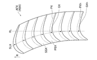
- FIG. 1A is an overall schematic perspective view showing a shape of a blade portion AFX of a moving blade (a moving blade of an axial turbine of a gas turbine engine) RBX of an axial flow fluid machine of the present disclosure.
- the overall structure of the moving blade RBX including the blade portion AFX is the same as that of the moving blade RB described with reference to FIG. 3, and thus duplicated description will be omitted.
- the wing portion AFX is formed by stacking the profiles PX in the span direction.
- the profiles PX at eight positions in the span direction including the hub portion and the tip portion of the blade portion AFX are shown.
- the shape of the profile PX at each position in the span direction is the same as the profiles P0 and P1 of the wing portions AF0 and AF1 described with reference to FIGS. 4A and 4B,
- the profile PXh in the hub portion, including its position is completely the same as the profiles P0h and P1h in the hub portion of the blades AF0 and AF1.
- the stacking line SLX of the wing portion AFX coincides with the straight line RL passing through the center of gravity GXh of the profile PXh in the hub portion and parallel to the radial direction R in the region on the hub side.
- the distance gradually deviates from the straight line RL as it goes to the chip side.
- the wing portion AFX has a shape that curves toward the suction surface SSX side in the circumferential direction from the intermediate portion in the span direction toward the tip side.
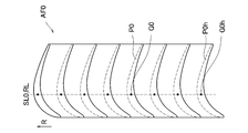
- FIG. 1B is a graph showing the shape of the stacking line SLX of the wing AFX.
- the vertical axis of the graph represents the position in the span direction
- the horizontal axis represents the displacement amount of the stacking line SLX in the circumferential direction (on the negative pressure surface SSX side).
- the spanwise position plotted on the vertical axis is the dimensionless value obtained by dividing the height measured from the hub of the blade by the total height of the blade (the height from the hub to the tip) as a percentage.
- the 0% span corresponds to the hub portion
- the 100% span corresponds to the tip portion.
- the shapes of the stacking lines SL0 and SL1 of the blade portions AF0 and AF1 of the conventional moving blade described in FIGS. 4A and 4B are also shown for comparison.
- the displacement amount of the blade AFX in the circumferential direction (on the negative pressure surface SSX side) of the stacking line SLX is zero in the portion from 0% span to 20% span, but from the 20% span to 100%.
- the area up to% span increases at an accelerating rate.
- the stacking line SLX of the wing portion AFX is a straight line parallel to the radial direction R in the portion from 0% span to 20% span and the diameter in the portion from 20% span to 100% span.
- the distance measured from the straight line (RL) parallel to the direction R to the negative pressure surface SSX side in the circumferential direction is a curve that gradually increases toward the tip portion. That is, the position in the span direction of the connection point between the straight line and the curved line forming the stacking line SLX of the wing portion AFX is 20% span.
- the displacement amount in the circumferential direction of the stacking line SL0 of the blade portion AF0 of the blade of the prior art shown for comparison is zero regardless of the position in the span direction, and the stacking line SL1 of the blade portion AF1 in the circumferential direction. Is zero at 0% span and increases linearly up to 100% span.
- the span direction position TP (hereinafter, referred to as the tilt start position) where the displacement amount of the stacking line SLX of the wing portion AFX starts to increase is set to 20% span, but this is.
- the inclination start position TP should be set to the radial outer end of the secondary flow region near the hub side end wall, which is grasped by analysis or test, or to the tip side from that.
- the amount of displacement in the circumferential direction of the stacking line SLX on the tip side from the tilt start position TP is the moment Mc caused by the centrifugal force Fc generated by tilting the stacking line SLX and the gas force acting on the blade portion AFX. It can be set appropriately in consideration of the magnitude relationship with the moment Mg caused by Fg. For example, as shown in FIG. 1B, even if the displacement amount of the stacking line SLX in the circumferential direction is zero in the portion from 0% span to 20% span, the displacement in the portion from 20% span to 100% span By appropriately setting the amount, it is possible to suppress the stress to be lower than that of the blade portion of the conventional blade. Even if the displacement amount is small, by appropriately setting it, it is possible to obtain the stress reduction effect equivalent to that of the conventional technique at any position in the span direction (see FIG. 2B).
- the stacking line SLX is not inclined in the circumferential direction at the portion where the secondary flow region is present in the vicinity of the hub-side end wall, thereby avoiding the influence on the secondary flow.
- the stacking line SLX is inclined in the circumferential direction toward the negative pressure surface SSX, thereby exerting the effect of reducing the bending stress acting on the blade portion AFX.
- FIG. 2A is a span of the total pressure loss coefficient obtained based on the result of analyzing the flow in the inter-blade flow path of the blade row configured by the blade AFX using CFD (Computational Fluid Dynamics).
- 6 is a graph showing a directional distribution in comparison with wing portions AF0 and AF1.
- FIG. 2B is a graph showing the distribution of the stress acting on the blade AFX in the span direction in comparison with the blade AF1.
- the peak of the total pressure loss coefficient due to the secondary flow loss is in the range of 0 to 20% span where the secondary flow region near the hub side end wall exists.
- the secondary flow loss is suppressed to a low level as compared with the conventional blade portion AF1 in which the whole is inclined toward the suction surface side in the circumferential direction (of the inclination in the circumferential direction). There is no equivalent level to the conventional wing AF0).
- the stress acting on the blade portion AFX is lower than that of the blade portion AF1 of the prior art in which the entire portion is inclined toward the suction surface side in the circumferential direction over almost the entire span direction. It is suppressed.
- the stress acting on the blade portion is suppressed lower than that of the blade portion AF1 of the related art, and at the same time, the secondary flow loss near the hub-side end wall is also reduced by the blade portion AF1 of the related art. It can be kept low compared to.
- the rotor blade of the present disclosure has been described as the rotor blade of the axial turbine of the gas turbine engine, but the present disclosure is not limited to this.
- the blades of the present disclosure are broadly applicable to axial flow fluid machines such as gas turbine engine fans or compressors, fans as a single unit, compressors or turbines.
- a blade of an axial flow fluid machine includes a blade portion that extends in a span direction from a hub portion to a tip portion and has a pressure surface and a suction surface, and the blade portion has an airfoil shape.
- the stacking line is formed by stacking the profiles having in the span direction, and the stacking line connecting the centers of gravity of the profiles at the respective positions in the span direction is located at a portion from the hub portion to the outer end of the secondary flow region near the hub portion.
- the distance from the hub portion to the connection point between the straight line and the curved line is 20% of the total height of the blade portion.
- the moving blade of the axial flow fluid machine includes a tip shroud coupled to the blade portion at the tip portion.
Abstract
Description
本開示の第1の態様の軸流流体機械の動翼は、ハブ部からチップ部までスパン方向に延びると共に正圧面と負圧面を有する翼部を備え、前記翼部は、翼型の形状を有するプロファイルを前記スパン方向に積み重ねることにより形成されており、各スパン方向位置における前記プロファイルの重心を連ねるスタッキングラインは、前記ハブ部から前記ハブ部近傍の二次流れ領域の外端までの部位においては、径方向に平行な直線であり、前記二次流れ領域の外端から前記チップ部までの部位においては、前記径方向に平行な直線から周方向に前記負圧面側へ計った距離が、前記チップ部へ向かって漸増する曲線である。 (Aspect of the present disclosure)
A blade of an axial flow fluid machine according to a first aspect of the present disclosure includes a blade portion that extends in a span direction from a hub portion to a tip portion and has a pressure surface and a suction surface, and the blade portion has an airfoil shape. The stacking line is formed by stacking the profiles having in the span direction, and the stacking line connecting the centers of gravity of the profiles at the respective positions in the span direction is located at a portion from the hub portion to the outer end of the secondary flow region near the hub portion. Is a straight line parallel to the radial direction, in the portion from the outer end of the secondary flow region to the tip portion, the distance measured from the straight line parallel to the radial direction to the negative pressure surface side in the circumferential direction, It is a curve that gradually increases toward the tip portion.
GX プロファイルの重心
PSX 正圧面
PX プロファイル
RBX 動翼
SLX スタッキングライン
SSX 負圧面
TS チップシュラウド AFX Blade GX Center of gravity of profile PSX Pressure surface PX Profile RBX Moving blade SLX Stacking line SSX Suction surface TS Chip shroud
Claims (3)
- 軸流流体機械の動翼であって、
ハブ部からチップ部までスパン方向に延びると共に正圧面と負圧面を有する翼部を備え、
前記翼部は、翼型の形状を有するプロファイルを前記スパン方向に積み重ねることにより形成されており、
各スパン方向位置における前記プロファイルの重心を連ねるスタッキングラインは、
前記ハブ部から前記ハブ部近傍の二次流れ領域の外端までの部位においては、径方向に平行な直線であり、
前記二次流れ領域の外端から前記チップ部までの部位においては、前記直線から周方向に前記負圧面側へ計った距離が、前記チップ部へ向かって漸増する曲線である、動翼。 A rotor blade of an axial fluid machine,
A wing portion that extends from the hub portion to the tip portion in the span direction and has a pressure surface and a suction surface,
The wing portion is formed by stacking profiles having an airfoil shape in the span direction,
The stacking line connecting the center of gravity of the profile at each span direction position is
In the portion from the hub portion to the outer end of the secondary flow region near the hub portion, it is a straight line parallel to the radial direction,
In the portion from the outer end of the secondary flow region to the tip portion, the moving blade is a curve in which the distance measured from the straight line to the suction surface side in the circumferential direction gradually increases toward the tip portion. - 前記ハブ部から、前記直線と前記曲線との接続点までの距離は、前記翼部の全高の20%である、請求項1に記載の動翼。 The moving blade according to claim 1, wherein the distance from the hub portion to the connection point between the straight line and the curved line is 20% of the total height of the blade portion.
- 前記チップ部において前記翼部に結合されたチップシュラウドを含む、請求項1または2に記載の動翼。 The moving blade according to claim 1 or 2, further comprising a tip shroud connected to the blade portion at the tip portion.
Priority Applications (4)
| Application Number | Priority Date | Filing Date | Title |
|---|---|---|---|
| JP2020556584A JP6959589B2 (en) | 2018-11-05 | 2019-05-22 | Blades of axial fluid machinery |
| CA3115079A CA3115079A1 (en) | 2018-11-05 | 2019-05-22 | Rotor blade of axial-flow fluid machine |
| EP19881673.8A EP3879072A4 (en) | 2018-11-05 | 2019-05-22 | Rotor blade of axial-flow fluid machine |
| US17/219,977 US11377959B2 (en) | 2018-11-05 | 2021-04-01 | Rotor blade of axial-flow fluid machine |
Applications Claiming Priority (2)
| Application Number | Priority Date | Filing Date | Title |
|---|---|---|---|
| JP2018-208241 | 2018-11-05 | ||
| JP2018208241 | 2018-11-05 |
Related Child Applications (1)
| Application Number | Title | Priority Date | Filing Date |
|---|---|---|---|
| US17/219,977 Continuation US11377959B2 (en) | 2018-11-05 | 2021-04-01 | Rotor blade of axial-flow fluid machine |
Publications (1)
| Publication Number | Publication Date |
|---|---|
| WO2020095470A1 true WO2020095470A1 (en) | 2020-05-14 |
Family
ID=70610834
Family Applications (1)
| Application Number | Title | Priority Date | Filing Date |
|---|---|---|---|
| PCT/JP2019/020316 WO2020095470A1 (en) | 2018-11-05 | 2019-05-22 | Rotor blade of axial-flow fluid machine |
Country Status (5)
| Country | Link |
|---|---|
| US (1) | US11377959B2 (en) |
| EP (1) | EP3879072A4 (en) |
| JP (1) | JP6959589B2 (en) |
| CA (1) | CA3115079A1 (en) |
| WO (1) | WO2020095470A1 (en) |
Families Citing this family (1)
| Publication number | Priority date | Publication date | Assignee | Title |
|---|---|---|---|---|
| DE102019210880A1 (en) * | 2019-07-23 | 2021-01-28 | MTU Aero Engines AG | ROTATING BLADE FOR A FLOW MACHINE |
Citations (6)
| Publication number | Priority date | Publication date | Assignee | Title |
|---|---|---|---|---|
| JPH01106903A (en) * | 1987-10-21 | 1989-04-24 | Toshiba Corp | Turbine nozzle |
| JPH10508671A (en) * | 1994-11-04 | 1998-08-25 | ユナイテッド テクノロジーズ コーポレイション | Blade with controlled tip leakage flow |
| JP2000018003A (en) * | 1998-06-30 | 2000-01-18 | Toshiba Corp | Turbine moving blade |
| JP2001193692A (en) * | 1999-12-06 | 2001-07-17 | General Electric Co <Ge> | Double-bent blade profile part of compressor |
| WO2005026501A1 (en) * | 2003-09-10 | 2005-03-24 | Hitachi, Ltd. | Turbine rotor blade |
| WO2012053024A1 (en) * | 2010-10-18 | 2012-04-26 | 株式会社 日立製作所 | Transonic blade |
Family Cites Families (21)
| Publication number | Priority date | Publication date | Assignee | Title |
|---|---|---|---|---|
| FR2556409B1 (en) * | 1983-12-12 | 1991-07-12 | Gen Electric | IMPROVED BLADE FOR A GAS TURBINE ENGINE AND MANUFACTURING METHOD |
| JP2753382B2 (en) | 1990-09-17 | 1998-05-20 | 株式会社日立製作所 | Axial flow turbine vane device and axial flow turbine |
| DE4228879A1 (en) | 1992-08-29 | 1994-03-03 | Asea Brown Boveri | Turbine with axial flow |
| FR2851798B1 (en) | 2003-02-27 | 2005-04-29 | Snecma Moteurs | TURBOREACTOR TURBINE BOW |
| JP2004285986A (en) | 2003-03-25 | 2004-10-14 | Toshiba Corp | Axial-flow turbine |
| GB2407136B (en) | 2003-10-15 | 2007-10-03 | Alstom | Turbine rotor blade for gas turbine engine |
| US7204676B2 (en) * | 2004-05-14 | 2007-04-17 | Pratt & Whitney Canada Corp. | Fan blade curvature distribution for high core pressure ratio fan |
| JP2006207554A (en) | 2005-01-31 | 2006-08-10 | Toshiba Corp | Turbine nozzle and axial-flow turbine using the same |
| JP2006299819A (en) | 2005-04-15 | 2006-11-02 | Ishikawajima Harima Heavy Ind Co Ltd | Turbine blade |
| JP2007009761A (en) | 2005-06-29 | 2007-01-18 | Toshiba Corp | Axial flow turbine |
| CH698109B1 (en) | 2005-07-01 | 2009-05-29 | Alstom Technology Ltd | Turbomachinery blade. |
| JP2007056824A (en) | 2005-08-26 | 2007-03-08 | Toshiba Corp | Stationary blade and moving blade for axial flow turbine, and axial flow turbine provided with same |
| US8480372B2 (en) * | 2008-11-06 | 2013-07-09 | General Electric Company | System and method for reducing bucket tip losses |
| JP4923073B2 (en) | 2009-02-25 | 2012-04-25 | 株式会社日立製作所 | Transonic wing |
| US20130259691A1 (en) * | 2009-07-17 | 2013-10-03 | General Electric Company | Perforated turbine bucket tip cover |
| JP2011074804A (en) | 2009-09-30 | 2011-04-14 | Hitachi Ltd | Nozzle of steam turbine |
| US9017036B2 (en) * | 2012-02-29 | 2015-04-28 | United Technologies Corporation | High order shaped curve region for an airfoil |
| FR2993323B1 (en) * | 2012-07-12 | 2014-08-15 | Snecma | TURBOMACHINE DAWN HAVING A PROFIL CONFIGURED TO OBTAIN IMPROVED AERODYNAMIC AND MECHANICAL PROPERTIES |
| EP2921647A1 (en) * | 2014-03-20 | 2015-09-23 | Alstom Technology Ltd | Gas turbine blade comprising bended leading and trailing edges |
| US10414486B2 (en) * | 2015-11-30 | 2019-09-17 | General Electric Company | Airfoil for a rotary machine including a propellor assembly |
| KR101997985B1 (en) * | 2017-10-27 | 2019-07-08 | 두산중공업 주식회사 | Modified J Type Cantilevered Vane And Gas Turbine Having The Same |
-
2019
- 2019-05-22 JP JP2020556584A patent/JP6959589B2/en active Active
- 2019-05-22 EP EP19881673.8A patent/EP3879072A4/en active Pending
- 2019-05-22 CA CA3115079A patent/CA3115079A1/en not_active Abandoned
- 2019-05-22 WO PCT/JP2019/020316 patent/WO2020095470A1/en unknown
-
2021
- 2021-04-01 US US17/219,977 patent/US11377959B2/en active Active
Patent Citations (6)
| Publication number | Priority date | Publication date | Assignee | Title |
|---|---|---|---|---|
| JPH01106903A (en) * | 1987-10-21 | 1989-04-24 | Toshiba Corp | Turbine nozzle |
| JPH10508671A (en) * | 1994-11-04 | 1998-08-25 | ユナイテッド テクノロジーズ コーポレイション | Blade with controlled tip leakage flow |
| JP2000018003A (en) * | 1998-06-30 | 2000-01-18 | Toshiba Corp | Turbine moving blade |
| JP2001193692A (en) * | 1999-12-06 | 2001-07-17 | General Electric Co <Ge> | Double-bent blade profile part of compressor |
| WO2005026501A1 (en) * | 2003-09-10 | 2005-03-24 | Hitachi, Ltd. | Turbine rotor blade |
| WO2012053024A1 (en) * | 2010-10-18 | 2012-04-26 | 株式会社 日立製作所 | Transonic blade |
Non-Patent Citations (1)
| Title |
|---|
| See also references of EP3879072A4 * |
Also Published As
| Publication number | Publication date |
|---|---|
| JP6959589B2 (en) | 2021-11-02 |
| JPWO2020095470A1 (en) | 2021-09-02 |
| US20210215048A1 (en) | 2021-07-15 |
| EP3879072A4 (en) | 2022-08-10 |
| CA3115079A1 (en) | 2020-05-14 |
| EP3879072A1 (en) | 2021-09-15 |
| US11377959B2 (en) | 2022-07-05 |
Similar Documents
| Publication | Publication Date | Title |
|---|---|---|
| JP5777531B2 (en) | Airfoil blades for axial turbomachinery | |
| JP6126995B2 (en) | Wings and platform assembly for subsonic flow | |
| US7740451B2 (en) | Turbomachine blade | |
| JP6877984B2 (en) | Turbomachinery and turbine blades for it | |
| US9546555B2 (en) | Tapered part-span shroud | |
| JP6461382B2 (en) | Turbine blade with shroud | |
| US9556741B2 (en) | Shrouded blade for a gas turbine engine | |
| US7794202B2 (en) | Turbine blade | |
| JP2016211542A (en) | Blade/disk dovetail backcut for blade/disk stress reduction for second stage of turbomachine | |
| WO2020095470A1 (en) | Rotor blade of axial-flow fluid machine | |
| US10982566B2 (en) | Turbine and gas turbine | |
| JP6955021B2 (en) | Snubbed wings with improved flutter resistance | |
| US20180030835A1 (en) | Turbine and gas turbine | |
| JP7106552B2 (en) | A steam turbine with an airfoil (82) having a backside camber. | |
| JP6905074B2 (en) | Blade with shroud with improved flutter resistance | |
| JP7162514B2 (en) | Axial turbomachinery and its blades | |
| JP2004263602A (en) | Nozzle blade, moving blade, and turbine stage of axial-flow turbine | |
| CN111448366B (en) | Multi-blade bucket for a turbine rotor and rotor comprising such a bucket | |
| KR102376903B1 (en) | Blade, compressor and gas turbine having the same | |
| JP2023509416A (en) | Diffuser with non-constant diffuser vane pitch and centrifugal turbomachine including such diffuser | |
| JP2021025489A (en) | Axial flow type fan and rotor blade for compressor | |
| JP2020176598A (en) | Axial flow compressor |
Legal Events
| Date | Code | Title | Description |
|---|---|---|---|
| 121 | Ep: the epo has been informed by wipo that ep was designated in this application |
Ref document number: 19881673 Country of ref document: EP Kind code of ref document: A1 |
|
| ENP | Entry into the national phase |
Ref document number: 2020556584 Country of ref document: JP Kind code of ref document: A |
|
| ENP | Entry into the national phase |
Ref document number: 3115079 Country of ref document: CA |
|
| NENP | Non-entry into the national phase |
Ref country code: DE |
|
| ENP | Entry into the national phase |
Ref document number: 2019881673 Country of ref document: EP Effective date: 20210607 |