WO2020090582A1 - Measuring device - Google Patents
Measuring device Download PDFInfo
- Publication number
- WO2020090582A1 WO2020090582A1 PCT/JP2019/041522 JP2019041522W WO2020090582A1 WO 2020090582 A1 WO2020090582 A1 WO 2020090582A1 JP 2019041522 W JP2019041522 W JP 2019041522W WO 2020090582 A1 WO2020090582 A1 WO 2020090582A1
- Authority
- WO
- WIPO (PCT)
- Prior art keywords
- flow path
- optical sensor
- liquid
- measurement
- flow
- Prior art date
Links
- 239000007788 liquid Substances 0.000 claims abstract description 165
- 230000003287 optical effect Effects 0.000 claims abstract description 164
- 238000005259 measurement Methods 0.000 claims abstract description 143
- 239000002245 particle Substances 0.000 claims abstract description 119
- 239000000758 substrate Substances 0.000 claims description 84
- 238000011084 recovery Methods 0.000 claims description 15
- 230000000052 comparative effect Effects 0.000 abstract description 3
- 238000000926 separation method Methods 0.000 description 36
- 239000000463 material Substances 0.000 description 16
- 230000007246 mechanism Effects 0.000 description 14
- 238000003756 stirring Methods 0.000 description 14
- 210000004369 blood Anatomy 0.000 description 9
- 239000008280 blood Substances 0.000 description 9
- 230000006866 deterioration Effects 0.000 description 9
- 238000010586 diagram Methods 0.000 description 9
- 239000004205 dimethyl polysiloxane Substances 0.000 description 9
- 229920000435 poly(dimethylsiloxane) Polymers 0.000 description 9
- 238000003825 pressing Methods 0.000 description 9
- 230000033001 locomotion Effects 0.000 description 8
- 210000000265 leukocyte Anatomy 0.000 description 7
- 238000000034 method Methods 0.000 description 7
- 239000011347 resin Substances 0.000 description 6
- 229920005989 resin Polymers 0.000 description 6
- 239000002699 waste material Substances 0.000 description 6
- 230000003321 amplification Effects 0.000 description 5
- 238000011088 calibration curve Methods 0.000 description 5
- 230000008859 change Effects 0.000 description 5
- 239000011521 glass Substances 0.000 description 5
- 230000005484 gravity Effects 0.000 description 5
- 238000003199 nucleic acid amplification method Methods 0.000 description 5
- 239000004065 semiconductor Substances 0.000 description 5
- 229920000089 Cyclic olefin copolymer Polymers 0.000 description 4
- 229920000178 Acrylic resin Polymers 0.000 description 3
- 239000004925 Acrylic resin Substances 0.000 description 3
- 230000007423 decrease Effects 0.000 description 3
- 210000003743 erythrocyte Anatomy 0.000 description 3
- 229920005668 polycarbonate resin Polymers 0.000 description 3
- 239000004431 polycarbonate resin Substances 0.000 description 3
- -1 polydimethylsiloxane Polymers 0.000 description 3
- 238000012545 processing Methods 0.000 description 3
- 239000004713 Cyclic olefin copolymer Substances 0.000 description 2
- 239000000470 constituent Substances 0.000 description 2
- 230000000694 effects Effects 0.000 description 2
- 239000004744 fabric Substances 0.000 description 2
- 238000007689 inspection Methods 0.000 description 2
- 238000012986 modification Methods 0.000 description 2
- 230000004048 modification Effects 0.000 description 2
- 239000003973 paint Substances 0.000 description 2
- 239000002504 physiological saline solution Substances 0.000 description 2
- 238000003860 storage Methods 0.000 description 2
- 229910019142 PO4 Inorganic materials 0.000 description 1
- 230000005856 abnormality Effects 0.000 description 1
- 239000000853 adhesive Substances 0.000 description 1
- 230000001070 adhesive effect Effects 0.000 description 1
- 238000005054 agglomeration Methods 0.000 description 1
- 230000002776 aggregation Effects 0.000 description 1
- 229910052782 aluminium Inorganic materials 0.000 description 1
- XAGFODPZIPBFFR-UHFFFAOYSA-N aluminium Chemical compound [Al] XAGFODPZIPBFFR-UHFFFAOYSA-N 0.000 description 1
- 230000008901 benefit Effects 0.000 description 1
- 230000005540 biological transmission Effects 0.000 description 1
- 210000004027 cell Anatomy 0.000 description 1
- 239000000919 ceramic Substances 0.000 description 1
- 238000006243 chemical reaction Methods 0.000 description 1
- 238000010924 continuous production Methods 0.000 description 1
- 239000003989 dielectric material Substances 0.000 description 1
- 239000006185 dispersion Substances 0.000 description 1
- PCHJSUWPFVWCPO-UHFFFAOYSA-N gold Chemical compound [Au] PCHJSUWPFVWCPO-UHFFFAOYSA-N 0.000 description 1
- 229910052737 gold Inorganic materials 0.000 description 1
- 239000010931 gold Substances 0.000 description 1
- 238000001746 injection moulding Methods 0.000 description 1
- 238000005304 joining Methods 0.000 description 1
- 230000031700 light absorption Effects 0.000 description 1
- 230000007774 longterm Effects 0.000 description 1
- 230000014759 maintenance of location Effects 0.000 description 1
- 229910052751 metal Inorganic materials 0.000 description 1
- 239000002184 metal Substances 0.000 description 1
- 239000007769 metal material Substances 0.000 description 1
- 150000002739 metals Chemical class 0.000 description 1
- NBIIXXVUZAFLBC-UHFFFAOYSA-K phosphate Chemical compound [O-]P([O-])([O-])=O NBIIXXVUZAFLBC-UHFFFAOYSA-K 0.000 description 1
- 239000010452 phosphate Substances 0.000 description 1
- 229920001296 polysiloxane Polymers 0.000 description 1
- 150000003839 salts Chemical class 0.000 description 1
- 238000012883 sequential measurement Methods 0.000 description 1
- 239000002904 solvent Substances 0.000 description 1
- 238000004544 sputter deposition Methods 0.000 description 1
- 239000000126 substance Substances 0.000 description 1
- 238000012360 testing method Methods 0.000 description 1
- 239000010409 thin film Substances 0.000 description 1
- 238000007740 vapor deposition Methods 0.000 description 1
Images


Classifications
-
- G—PHYSICS
- G01—MEASURING; TESTING
- G01N—INVESTIGATING OR ANALYSING MATERIALS BY DETERMINING THEIR CHEMICAL OR PHYSICAL PROPERTIES
- G01N35/00—Automatic analysis not limited to methods or materials provided for in any single one of groups G01N1/00 - G01N33/00; Handling materials therefor
- G01N35/00029—Automatic analysis not limited to methods or materials provided for in any single one of groups G01N1/00 - G01N33/00; Handling materials therefor provided with flat sample substrates, e.g. slides
- G01N35/00069—Automatic analysis not limited to methods or materials provided for in any single one of groups G01N1/00 - G01N33/00; Handling materials therefor provided with flat sample substrates, e.g. slides whereby the sample substrate is of the bio-disk type, i.e. having the format of an optical disk
-
- G—PHYSICS
- G01—MEASURING; TESTING
- G01N—INVESTIGATING OR ANALYSING MATERIALS BY DETERMINING THEIR CHEMICAL OR PHYSICAL PROPERTIES
- G01N15/00—Investigating characteristics of particles; Investigating permeability, pore-volume, or surface-area of porous materials
- G01N15/06—Investigating concentration of particle suspensions
-
- G01N15/01—
-
- G01N15/075—
-
- G—PHYSICS
- G01—MEASURING; TESTING
- G01N—INVESTIGATING OR ANALYSING MATERIALS BY DETERMINING THEIR CHEMICAL OR PHYSICAL PROPERTIES
- G01N15/00—Investigating characteristics of particles; Investigating permeability, pore-volume, or surface-area of porous materials
- G01N15/06—Investigating concentration of particle suspensions
- G01N2015/0687—Investigating concentration of particle suspensions in solutions, e.g. non volatile residue
-
- G—PHYSICS
- G01—MEASURING; TESTING
- G01N—INVESTIGATING OR ANALYSING MATERIALS BY DETERMINING THEIR CHEMICAL OR PHYSICAL PROPERTIES
- G01N35/00—Automatic analysis not limited to methods or materials provided for in any single one of groups G01N1/00 - G01N33/00; Handling materials therefor
- G01N35/00029—Automatic analysis not limited to methods or materials provided for in any single one of groups G01N1/00 - G01N33/00; Handling materials therefor provided with flat sample substrates, e.g. slides
- G01N2035/00099—Characterised by type of test elements
- G01N2035/00158—Elements containing microarrays, i.e. "biochip"
Definitions
- the present disclosure relates to a measuring device that causes a liquid containing a particle to be measured and a liquid to be compared to flow in respective flow channels to measure with an optical sensor.
- a liquid containing particles to be measured for example, a liquid such as blood containing white blood cells and the like, and a liquid to be compared not containing the particles, for example, a liquid such as physiological saline for calibration have a so-called micro flow path.
- various measurements are performed on a liquid containing particles to be measured by supplying it to a reaction device or a microchip (see, for example, Japanese Patent Application Laid-Open No. 2001-74724 and International Publication No. 2009/145022). ..
- the measuring device of the present disclosure includes a first flow path having a measurement region in which a first liquid containing particles to be measured is caused to flow and the particles in the first liquid are measured by an optical sensor, a comparison target not containing the particles.
- a second flow path having a comparison area for comparing and measuring the second liquid with the optical sensor, and a flow path device having a calibration area for calibrating the optical sensor; a light emitting element;
- the optical sensor having a light receiving element is arranged at a first end and a drive shaft is arranged at a second end, and an arm-shaped member connected to the drive shaft to drive the arm-shaped member to rotate within a predetermined range.
- the measurement area, the comparison area, and the calibration area each include a circumferential position at which the optical sensor moves as the arm member is driven to rotate. It is disposed as a region.
- the example of embodiment of the measuring device of this indication is shown, (a) is a top view and (b) is a side view.
- the other example of embodiment of the measuring device of this indication is shown, (a) is a top view and (b) is a side view.
- FIG. 1 It is sectional drawing which shows the example of the optical sensor in the measuring device of this indication.
- (A) is a sectional view showing a part of an example of a measuring device of this indication, and (b) is a figure explaining a measuring mechanism. It is sectional drawing which shows some other examples of the measuring device of this indication. It is a top view which shows the other example of the measuring device of this indication. It is sectional drawing which shows some other examples of the measuring device of this indication. It is a block diagram which shows typically the one part structure of the other example of the measuring device of this indication. It is a top view which shows some other examples of the flow path device in the measuring device of this indication. It is a top view which shows some other examples of the flow path device in the measuring device of this indication.
- each liquid is caused to flow through a flow path such as a micro flow path, and measurement is performed in a predetermined region of the flow path. ..
- an optical sensor is arranged for each of the two flow paths to perform simultaneous measurement, or one optical sensor performs sequential measurement.
- the first liquid containing the particles to be measured is flowed, and the first flow path having the measurement region and the second liquid to be compared containing no particles are flowed to have the comparison region.
- An optical sensor having a light emitting element and a light receiving element is arranged at a first end, and a drive shaft to which a rotation driving actuator is connected is arranged at a second end with respect to a flow path device having a second flow path. Since the measurement area and the comparison area are arranged at the circumferential position where the optical sensor moves in accordance with the rotation driving of the arm-shaped member, the measurement device can be downsized accurately and accurately. Stable measurement can be performed. In addition, since the flow path device has the calibration region arranged at the circumferential position where the optical sensor moves, the optical sensor can be calibrated as necessary during measurement. Accurate and stable measurement can be performed by reducing the influence of variation or deterioration.
- an orthogonal coordinate system (X, Y, Z) is defined for convenience, and the positive side in the Z-axis direction is the upper side, but in the present disclosure, any direction may be the upper side or the lower side. ..
- the following contents exemplify the embodiments of the present disclosure, and the present disclosure is not limited to these embodiments. It goes without saying that various modifications may be made without departing from the scope of the present disclosure.
- FIG. 1A and 1B are diagrams showing an example of an embodiment of a measuring device of the present disclosure
- FIG. 1A is a top view
- FIG. 1B is a side view.
- a part is shown in a see-through manner, and the other part is shown in duplicate for the purpose of explaining the operation.
- the measuring apparatus 1 of this example is for supplying the first liquid to be inspected and the second liquid to be compared to the first inflow port and the second inflow port of the inspection device (not shown), respectively. is there.
- the measuring apparatus 1 includes a first flow path 5 having a measurement region 105 in which a first liquid containing particles to be measured is caused to flow and particles in the first liquid are measured by the optical sensor 3, a comparison target not containing particles.
- a second channel 6 having a comparison region 106 through which the second liquid flows and the second sensor compares and measures the second liquid, and a channel device 2 having a calibration region 107 for calibrating the optical sensor 3. ing.
- the optical sensor 3 having the light emitting element and the light receiving element is arranged at the first end (the left end in the drawing), and the drive shaft 101 is arranged at the second end (the right end in the drawing). Is equipped with. Further, it is provided with a rotary drive actuator 102 which is connected to the drive shaft 101 and rotationally drives the arm member 100 within a predetermined range.
- the measurement area 105, the comparison area 106, and the calibration area 107 in the flow path device 2 are arranged in a circumferential position (virtual in FIG. 1A) where the optical sensor 3 moves as the arm member 100 is rotationally driven. Is indicated by a one-dot chain line).
- the measurement area 105 (first flow path 5), the comparison area 106 (second flow path 6) and the calibration area 107 (FIG. 1) located inside the flow path device 2 are shown.
- the positions of (b) are omitted in the drawing).
- the optical sensor 3 and the arm-shaped member 100 are shown by seeing through the flow path device 2, and the case where the optical sensor 3 faces each of the regions 105, 106, 107 overlaps.
- the optical sensor 3 is within a predetermined range (a circle with the drive shaft 101 as the center of rotation) by the arm-shaped member 100 in which the rotary drive actuator 102 is connected to the drive shaft 101.
- the measurement region 105 and the comparison region 106 are arranged as a region including a circumferential position where the optical sensor 3 moves as the arm member 100 is driven to rotate.
- the measurement in the measurement region 105 and the comparison measurement in the comparison region 106 can be sequentially performed with a slight movement of the arm-shaped member 100. As a result, the measurement can be easily and accurately performed, and the driving mechanism of the optical sensor 3 does not become large, so that the measuring device 1 can be downsized.
- the calibration area 107 used for the calibration of the optical sensor 3 is also arranged as an area including the circumferential position where the optical sensor 3 moves, the calibration area 107 of the optical sensor 3 is set as a zero point on each measurement.
- the characteristic can be calibrated, the influence of the variation of the characteristic of the optical sensor 3 can be reduced, and stable and accurate measurement can be performed.
- the measurement in the measurement region 105 by the optical sensor 3, the comparison measurement in the comparison region 106, and the calibration in the calibration region 107 can be easily performed in a desired order.
- the measuring device 1 of the present disclosure uses, for example, blood as the first liquid, and handles cells such as white blood cells as particles to be measured in the first liquid, so that the optical sensor 3 optically determines the concentration of the particles. It can be measured and functions as a particle concentration measuring device.
- physiological saline Phosphate Buffered Salts: PBS
- PBS Phosphate Buffered Salts
- the particles to be measured other particles made of various inorganic or organic substances can be applied, and the first liquid and the second liquid, which are suitable media, can be used for both of them.
- the measuring device 1 of the present disclosure functions as a particle concentration measuring device capable of optically measuring the concentrations of various particles in the first liquid.
- the configuration in the example of the flow channel device 2 will be described in detail later, but as a basic configuration, the first liquid and the second liquid are supplied from the upper surface side of the flow channel device 2, and the liquid for which measurement has been completed is the flow channel. It is discharged from the lower surface side of the device 2 and collected or discarded. Therefore, the optical sensor 3 is arranged on the lower surface side of the flow path device 2. However, since the supply and discharge of the first liquid and the second liquid may be performed from either the upper surface side or the lower surface side of the flow channel device 2, the optical sensor 3 may be connected to the flow channel device 2 depending on the configuration of the flow channel device 2. It may be arranged on the upper surface side of the device 2.
- the flow channel device 2 performs optical measurement on the first liquid and the second liquid in the measurement region 105 and the comparison region 106, at least these regions are translucent, but other parts are translucent. It may be transparent or non-translucent.
- the calibration area 107 does not necessarily have to be integrally arranged on the substrate of the flow path device 2 having the measurement area 105 and the comparison area 106.
- a part of a stage (not shown) for setting the flow channel device 2 for measurement is set as a member that integrally configures the flow channel device 2, and the member that configures the flow channel device 2 is set.
- the calibration area 107 may be arranged. According to this, even when the plurality of flow path devices 2 are replaced with the replacement of the plurality of first liquids, it is possible to calibrate the optical sensor 3 with the same reference by the same calibration region 107, and it is possible to accurately perform the calibration. This is advantageous for stable measurement.
- the calibration area 107 functions as a reference (zero point) for optical measurement, when the calibration area 107 is integrally arranged on the substrate of the flow channel device 2, a plurality of flow channel devices 2 are replaced.
- the characteristics of the calibration region 107 can be set as a reference according to the characteristics of the measurement object, for example, when the characteristics of the measurement object change, and thus various measurements can be performed. Can be adapted.
- the optical sensor 3 has a light emitting element and a light receiving element, and irradiates the light emitted from the light emitting element to the measurement region 105 in which the first liquid is present, the comparison region 106 in which the second liquid is present, and the calibration region 107.
- the output current thereof can be detected to optically measure the object.
- the arm-shaped member 100 is rotationally driven by the rotational driving actuator 102, and moves the optical sensor 3 in a circumferential shape around the drive shaft 101.
- the shape and size of the arm-shaped member 100 may be appropriately set according to the configuration of the flow path device 2 and so that desired strength and accuracy can be secured when the optical sensor 3 moves.
- the material of the arm-shaped member 100 various materials such as various resins, metals, glass, and ceramics can be selected as long as desired strength, accuracy, and durability can be secured.
- the arm-shaped member 100 is not limited to one configured as a single member as a whole, but may be configured by appropriately combining parts of each part.
- the drive shaft 101 is connected to the rotary drive shaft of the rotary drive actuator 102 and the second end of the arm-shaped member 100, and functions as a center point for rotationally driving the arm-shaped member 100 at a desired rotation angle and speed.
- various driving means can be used as long as the arm-shaped member 100 can be accurately driven to rotate at a predetermined position.
- various motors such as a pulse motor (also referred to as a stepping motor) and a servo motor may be directly connected to the drive shaft 101 or connected via a gear mechanism, and of course, a slider crank mechanism or a linear motion is converted into a rotary motion.
- a pulse motor also referred to as a stepping motor
- a servo motor may be directly connected to the drive shaft 101 or connected via a gear mechanism, and of course, a slider crank mechanism or a linear motion is converted into a rotary motion.
- a syringe having a gear mechanism such as a rack and pinion, a piezo actuator, or a linear motor.
- Rotational drive by a pulse motor is suitable as a drive unit for moving the optical sensor 3 in the present disclosure because it is easy to control, can be rotationally driven by high torque at low speed, and has good positioning accuracy. Further, in order to perform the optical measurement by the optical sensor 3, it is important to position the optical sensor 3 in each region and hold the optical sensor 3 in a stationary state in that area. Motors are preferred.
- a predetermined calculation is performed by inputting an output current from a power supply unit for supplying electric power to the light emitting element in the optical sensor 3 to cause the light emitting element to emit light. It also includes a processing unit for performing processing, and a control unit having a drive control unit for causing the rotation driving actuator 102 to perform desired rotation driving.
- a power supply unit for supplying electric power to the light emitting element in the optical sensor 3 to cause the light emitting element to emit light. It also includes a processing unit for performing processing, and a control unit having a drive control unit for causing the rotation driving actuator 102 to perform desired rotation driving.
- Various known circuits or devices can be applied to each of these parts.
- the flow path device 2 is arranged on the opposite side of the optical sensor 3, that is, on the upper surface side in this example, corresponding to the measurement region 105 and the comparison region 106. It is preferable to have a reflective member 24 or a non-reflective member 24.
- the reflecting member 24 receives the light emitted from the light emitting element of the optical sensor 3 that has passed through each of the first flow path 5 of the measurement region 105 and the second flow path 6 of the comparison region 106, and receives the light of the optical sensor 3. Can be reflected to the element.
- the non-reflective member 24 is configured to measure the light loss when the light passing through each of the first flow path 5 in the measurement area 105 and the second flow path 6 in the comparison area 106 has a large DC offset component. Can be prevented, and the incidence of ambient light can be prevented.
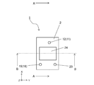
- FIG. 2 is a diagram showing another example of the embodiment of the measuring device of the present disclosure
- FIG. 2 (a) is a top view
- FIG. 2 (b) is a side view
- a part flow channel device 2
- another part arm-shaped member 100, etc.
- the flow channel device 2 has the first flow outlet 13 to which the first flow channel 5 is connected and the first liquid flows out within the movable range of the arm-shaped member 100.
- the arm-shaped member 100 has a first liquid recovery container 108 which is arranged corresponding to the first outlet 13 and recovers the first liquid flowing out from the first outlet 13. According to this, the first liquid that has been measured in the measurement region 105 of the first flow path 5 is caused to flow out from the first outlet 13, and the first liquid is positioned so as to correspond to the first outlet 13. The first liquid is recovered by the first liquid recovery container 108, and then the arm-shaped member 100 is rotatably moved to the outside of the flow channel device 2 and to the outside of the stage on which the flow channel device 2 is mounted.
- the recovery container 108 can be easily replaced to recover or discard the first liquid.
- the first liquid recovery container 108 in the measuring device 1 of this example extends the first end of the arm-shaped member 100 and is positioned closer to the first end than the optical sensor 3. It is placed in the extended part.
- the first liquid recovery container 108 is moved to the outside of the flow path device 2 to recover or discard the first liquid, there is an advantage that the distance of the rotational movement of the arm-shaped member 100 can be small. ..
- the position of the first liquid recovery container 108 arranged in the arm-shaped member 100 may be aligned with the position of the first outflow port 13 in the flow channel device 2, and may be for recovery outside the flow channel device 2.
- the arm-shaped member 100 may be arranged on the first end side or the second end side of the optical sensor 3.
- the first outlet 13 is formed as a first opening 11 located on the upper surface or the lower surface of the flow path device 2, as described later.
- the first liquid that flows out from the first outlet 13 does not necessarily have to be recovered by the first liquid recovery container 108.
- the first outlet 13 is arranged outside the movable range of the arm-shaped member 100, and the first liquid is irrespective of the movement of the arm-shaped member 100 by a separately arranged collection container or a tube connected for collection. You may be able to collect.
- it is preferable that the first outlet 13 is arranged on the lower surface of the flow path device 2 and the first liquid is recovered by utilizing gravity, but the first outlet 13 is arranged on the upper surface of the flow path device 2. Then, a recovery container, a tube, or the like may be connected, and the first liquid pushed out from the first flow path 5 and flowing out may be absorbed or sucked to be recovered.
- FIGS. 3 to 5 show a part of other examples of the measurement device of the present disclosure.
- FIG. 3 is a top view of the measuring device 1.
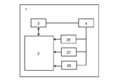
- FIG. 4 is a block diagram schematically showing the configuration of the measuring device 1.
- FIG. 5 is a cross-sectional view of the measuring device 1, and is a cross-sectional view when the measuring device 1 is cut along the line AA shown in FIG.
- a mechanism for rotationally driving the optical sensor 3 is not shown.
- the measuring device 1 can measure specific particles in a liquid.
- the measuring device 1 includes a flow channel device 2, an optical sensor 3, and a control unit 4. Note that the illustration of the mechanism that rotationally drives the optical sensor 3 is omitted.
- the optical sensor 3 is movably arranged so as to face a measurement region and a comparison region of a predetermined flow channel of the flow channel device 2, irradiates the first liquid with light, and transmits the light (after passing through the first liquid). The light reflected, passed again, and returned) can be received.
- the control unit 4 can estimate and measure the number of particles based on the output of the optical sensor 3.
- the first liquid is a liquid containing particles to be measured, and is a sample when it is an inspection target by measurement.
- the control unit 4 compares the light intensity and the calibration curve to obtain the concentration of particles. Can be measured.
- FIG. 6 schematically shows an example of the flow channel device 2.
- FIG. 6 is a top view of the flow channel device 2 as seen through from above.
- the line AA in FIG. 6 corresponds to the line AA in FIG.
- the flow channel device 2 is a measurement flow channel for measuring particles in the first liquid.
- the flow channel device 2 has a transparent first flow channel 5 and a second flow channel 6.
- the first liquid which is a measurement target including particles, flows through the first flow path 5.
- a second liquid which is a comparison target and does not contain particles, flows through the second flow path 6.
- the first channel 5 is a channel for measurement
- the second channel 6 is a channel for comparative measurement.
- the first liquid is a sample in the test, and blood, for example, is assumed.
- the second liquid is a liquid for comparison, and for example, PBS or the like can be used.
- the optical sensor 3 can sense particles in the first liquid. At the time of measurement, the optical sensor 3 irradiates the first flow path 5 and the second flow path 6 with light, and also receives the respective light that has passed through the first flow path 5 and the second flow path 6.
- the optical sensor 3 has a light emitting element 7 and a light receiving element 8.
- the light emitting element 7 may be, for example, an LED (Light Emitting Diode) or an LD (Laser Diode), and the light emitting element 7 of this example is an LED.
- the light receiving element 8 may be, for example, a PD (Photo Diode).
- the control unit 4 controls the measuring device 1.
- the control unit 4 compares the intensity of the light (first light) passing through the first flow path 5 and the intensity of the light (second light) passing through the second flow path 6 by the optical sensor 3, Particles in the first liquid can be measured. That is, the control unit 4 can measure the particles by calculating the intensity difference between the first light and the second light and comparing the intensity difference between the first light and the second light with the calibration curve.
- the conventional measuring device if the conventional measuring device is repeatedly used, the light emitting element of the optical sensor deteriorates and the light intensity decreases. That is, when an optical sensor is used to measure a particle from a change in the light intensity by utilizing the dispersion and absorption of light of the particle, for example, when the light intensity decreases due to deterioration of an optical element, the number of particles It is mistaken for the measurement result that there is more than the original number.
- the particles are measured from the intensity difference between the first light and the second light, so that the measurement accuracy is not affected by the deterioration of the optical element. It can be maintained or improved.
- the flow channel device 2 functions as a flow channel for measurement and comparison as described above.
- at least the measurement region of the first flow channel 5 and the comparison region of the second flow channel 6 have translucency so that the optical sensor 3 measures the particles in the first liquid.
- the flow channel device 2 has, for example, a plate shape.
- the flow channel device 2 of this example is formed mainly by bonding the first substrate 9 and the second substrate 10.
- the flow channel device 2 has a first substrate 9 having a groove and a second substrate 10 arranged on the surface of the first substrate 9.
- the second substrate 10 closes the opening of the groove of the first substrate 9. That is, the groove of the first substrate 9 and the surface of the second substrate 10 form the first flow path 5 and the second flow path 6.
- the flow channel device 2 may have members other than the first substrate 9 and the second substrate 10.
- the first substrate 9 is, for example, a flat member.
- the material of the first substrate 9 may be, for example, glass, acrylic resin, polycarbonate resin, cyclic olefin copolymer (COC) resin, cycloolefin polymer (COP) resin, polydimethylsiloxane (PDMS) resin, or the like.
- the material of the first substrate 9 in this example is PDMS.
- the refractive index of the first substrate 9 is set to 1.4 to 1.6, for example.
- the width of the groove of the first substrate 9 may be, for example, 500 to 4000 ⁇ m (0.5 to 4 mm).
- the depth of the groove may be, for example, 100 to 1000 ⁇ m (0.1 to 1 mm).
- the first substrate 9 and the groove of the first substrate 9 can be formed by a conventionally known method.
- the thickness of the groove of the first substrate 9 from the bottom surface is set to, for example, 0.5 to 1 mm.
- the width and depth of the groove of the first substrate 9 are the same as the width and height of the first flow channel 5 and the second flow channel 6.
- the second substrate 10 is, for example, a flat member.
- the material of the second substrate 10 may be, for example, glass, acrylic resin, polycarbonate resin, polydimethylsiloxane (PDMS) resin, or the like.
- the refractive index of the second substrate 10 is set to 1.4 to 1.6, for example.
- the material of the second substrate 10 in this example is glass.
- the second substrate 10 can be formed by a conventionally known method.
- the thickness of the second substrate 10 is set to, for example, 0.5 to 1 mm.
- the thickness of the second substrate 10 is set smaller than that of the first substrate 9.
- first substrate 9 is arranged on the upper side, in the flow channel device 2 of this example, the first substrate 9 is arranged on the upper surface of the second substrate 10. ..
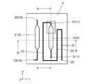
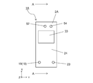
- FIG. 7 schematically shows a part of the flow channel device 2.
- FIG. 7 is an enlarged top view of the broken line portion in FIG.
- the first flow path 5 is a flow path into which at least the first liquid flows.
- the first channel 5 has a plurality of first openings 11 located on both sides of the channel device 2.
- the plurality of first openings 11 may be at least openings through which the first liquid flows in and out.
- the plurality of first openings 11 are arranged on the upper surface of the flow path device 2 (the upper surface of the second substrate 10) and the lower surface of the flow path device 2 (the lower surface of the first substrate 9).
- a first outlet 13 The first inflow port 12 is an opening for liquid to flow into the first flow path 5.
- the first outlet 13 is an opening through which the liquid flows out from the first flow path 5. Then, an external container or tube is connected so as to supply the first liquid to the first inlet 12.
- the first flow path 5 is connected to the first inflow port 12 and extends in the thickness direction, and a flat portion that is connected to the vertical portion 14 and extends in one direction of the plane. It further has 15 and.
- the vertical portion 14 is a through hole formed in the first substrate 9.
- the plane portion 15 is a groove formed in the first substrate 9.
- the shape of the cross section (cross section orthogonal to the moving direction of the liquid) of the flat surface portion 15 may be, for example, a rectangular shape.
- the flat surface portion 15 further has a first flat surface portion 16 connected to the vertical portion 14, and a second flat surface portion 17 connected to the first flat surface portion 16 and having a width larger than that of the first flat surface portion 16. You may have.
- the connecting portion between the first flat surface portion 16 and the second flat surface portion 17 is gradually widened.
- the irradiation area of the light emitting element 7 of the optical sensor 3 is the second plane portion 17, and this irradiation area is the measurement area 105 shown in FIG.
- the height of the second flat portion 17 may be higher than that of the first flat portion 16. Thereby, the particles can be easily diffused in the first liquid.
- the height of the first flat surface portion 16 may be, for example, 0.2 to 1 mm.
- the height of the second flat surface portion 17 may be, for example, 1 to 5 mm.
- the second flow path 6 is a flow path into which at least the second liquid flows.
- the second flow path 6 has a plurality of second openings 18 located on either side of the flow path device 2.
- the plurality of second openings 18 may be at least openings through which liquid flows in and out.
- the plurality of second openings 18 are arranged on the upper surface of the channel device 2 (the upper surface of the first substrate 9) and the second inlet port 19 and on the lower surface of the channel device 2 (the lower surface of the second substrate 10).
- a second outlet 20 is connected so as to supply the second liquid to the second inlet 19.
- the second flow path 6 is connected to the second inflow port 19 and extends in the thickness direction, and a vertical portion (not shown), which is connected to the vertical portion and extends in one direction of the plane. It further has the 3rd plane part 21 which exists.
- a part of the third flat surface portion 21 of the second flow path 6 may have at least the same shape as the second flat surface portion 17 of the first flow path 5, for example.
- the irradiation area of the light emitting element 7 of the optical sensor 3 on the third plane portion 21 becomes the comparison area 106 shown in FIG.
- the position in the thickness direction of a part of the third flat surface portion 21 having the same shape as the second flat surface portion 17 may be the same position as the first flow path 5, for example.
- the second flow path 6 may not have the same shape and the same position as the first flow path 5 as long as it can function as a comparison flow path.
- the flow channel device 2 may further have a third flow channel 22 connected to the first flow channel 5 in addition to the first flow channel 5. Then, the third flow path 22 may be connected to the flat surface portion 15 of the first flow path 5. The third flow path 22 has a function of pushing away the sample that has reached the flat portion 15 by flowing gas or the like. As a result, the retention of the sample in the first channel 5 (15) can be reduced.
- the third flow channel 22 is arranged so as to be connected to the connecting portion between the vertical portion 14 and the flat surface portion 15 of the first flow channel 5. Further, the third flow path 22 has a third opening 23 located on the surface of the flow path device 2 (the upper surface of the first substrate 9 in this example). The third opening 23 is an opening for injecting the extruding liquid for pushing out the sample.
- the flow channel device 2 of this example may further include a reflecting member 24 such as a mirror member, which is arranged in a region on the upper surface of the second substrate 10 overlapping the first flow channel 5 and the second flow channel 6. Good.
- the reflecting member 24 may reflect the light, which is emitted from the light emitting element 7 of the optical sensor 3 and has passed through each of the first flow path 5 and the second flow path 6, to the light receiving element 8 of the optical sensor 3. it can.
- the optical sensor 3 irradiates a region overlapping the first flow channel 5 and the second flow channel 6 on the side opposite to the optical sensor 3 with respect to the first flow channel 5 and the second flow channel 6.
- the reflecting member 24 that reflects the light toward the optical sensor 3
- the light emitted by the optical sensor 3 can be efficiently received by the optical sensor 3 through the first flow path 5 and the second flow path 6. .
- the disturbance light that enters the first flow path 5 and the second flow path 6 from the side opposite to the optical sensor 3 can be blocked by the reflecting member 24, the accuracy of measurement by the optical sensor 3 can be ensured satisfactorily. can do.
- the reflecting member 24 may be a thin film member, for example.
- the material of the reflecting member 24 may be a material having a refractive index different from that of the first substrate 9.
- the material of the reflecting member 24 can be formed of, for example, a metal material such as aluminum or gold, or a laminated body of dielectric materials such as a dielectric multilayer filter.
- the refractive index of the reflecting member 24 is set to 1.4 to 1.6, for example.
- the reflection member 24 can be formed on the upper surface of the first substrate 9 by a method such as a vapor deposition method or a sputtering method.
- the reflecting member 24 is arranged so as to overlap the first flow path 5 and the second flow path 6 as will be described later, but the first flow path 5 and the second flow path 6 are provided. However, it is not limited to an integral one that covers both of the above, and may be separately arranged so as to overlap with each of the first flow path 5 and the second flow path 6.
- a light shielding member may be arranged between the reflecting members 24 in order to shield ambient light.
- a non-reflecting member (light-shielding member) is arranged on the reflecting member 24 or in place of the reflecting member 24, and the non-reflecting member is provided. The transmission of light and the incidence of ambient light may be prevented by 24.
- the optical sensor 3 is provided in a region overlapping the first flow channel 5 and the second flow channel 6 on the side opposite to the optical sensor 3 with respect to the first flow channel 5 and the second flow channel 6.
- the non-reflecting member 24 that does not reflect the light emitted by the optical sensor 3
- the light emitted by the optical sensor 3 is reflected by the particles contained in the first flow passage 5, or the first flow passage 5 and the second flow passage.
- the light reflected by the interface of 6 (the ceiling surface viewed from the optical sensor 3 side) can be received by the optical sensor 3.
- the DC offset can be optically performed by measuring the reflection from the interface, and the light reflected by the particles can be satisfactorily received.
- the non-reflective member 24 can reliably block the disturbance light entering from the side opposite to the optical sensor 3 with respect to the first flow path 5 and the second flow path 6, the optical noise can be removed.
- the accuracy of measurement by the sensor 3 can be improved.
- a non-reflection cloth or the like can be used.
- a non-reflective member 24 may be formed by applying a matte paint such as black.
- the non-reflective member 24 is integrated so as to cover both the first flow path 5 and the second flow path 6 over the entire region measured by the optical sensor 3. Preferably.
- the flow channel device 2 of this example has a calibration area 107 in the non-reflective area, as shown in the sectional view of FIG.
- the non-reflective region can be a region of the flow channel device 2 where the first flow channel 5 and the second flow channel 6 are absent, and where the reflective member 24 is not arranged when viewed from above. ..
- a non-reflecting member 107a for reference that does not reflect the light emitted by the optical sensor 3 may be arranged in this non-reflecting region.
- the non-reflective member 107a can be used for calibration of the light receiving element 8 of the optical sensor 3, and serves as a reference when the measurement is performed by the optical sensor 3.
- the portion where the non-reflective member 107a is arranged serves as the portion that functions as the calibration area 107.
- a non-reflective cloth or the like may be installed, and may be formed by applying a black matting paint or the like.
- the non-reflective member 107a may be arranged on the lower surface of the second substrate 10 corresponding to the non-reflective region in a region that does not overlap the first flow channel 5 and the second flow channel 6.
- the portion where the non-reflective member 107a is arranged also serves as the calibration area 107. Also in this case, the influence of noise generated when the optical sensor 3 is used can be reduced by using the intensity of the reflected light from the non-reflecting member 107a as a reference.
- the measuring apparatus 1 of this example supplies a first pump 26 that supplies a first liquid to the first flow path 5 and a second liquid to the second flow path 6 as schematically shown in the block diagram of FIG. It further has a second pump 27 and a third pump 28 that supplies gas (hereinafter, also referred to as gas) to the third flow path 22.
- the first pump 26, the second pump 27, and the third pump 28 are respectively connected to the first opening 11, the second opening 18, and the third opening 23 via a plurality of other flow paths (not shown) such as tubes. I understand.
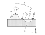
- FIG. 8 schematically shows an example of the optical sensor 3.
- FIG. 8 is an enlarged sectional view of the optical sensor 3 shown in FIG.
- the optical sensor 3 is a sensor for measuring particles in the first liquid.
- the optical sensor 3 has the light emitting element 7 and the light receiving element 8.
- the light receiving element 8 of the present example has a semiconductor substrate 29 having a region 29a of one conductivity type and a region 29b of another conductivity type on the upper surface, and a pair of first electrodes 30.
- the light emitting element 7 of this example has a plurality of semiconductor layers 31 arranged apart from the portion of the semiconductor substrate 29 that functions as the light receiving element 8, and a pair of second electrodes 32.
- the optical sensor 3 is installed movably in the plane direction on the surface of the flow path device 2 by rotationally driving the arm member 100.
- the measurement apparatus 1 can sequentially irradiate the measurement area 105 of the first flow path 5, the comparison area 106 and the calibration area 107 of the second flow path 6 with light while moving the optical sensor 3. Yes, the individual light intensity for each can be measured.
- the optical sensor 3 since the light emitting element 7 and the light receiving element 8 are integrally arranged on one semiconductor substrate 29, the optical sensor 3 can be downsized and the focal length of the optical sensor 3 can be shortened. Therefore, it is possible to accurately measure even a minute area.
- the configuration of the optical sensor 3 is not limited to this, and one optical sensor 3 is provided on one substrate.
- the light emitting element 7 and the light receiving element 8 may be separately mounted and they may be integrally arranged.
- the control unit 4 can control various operations in the measuring device 1. Specifically, the control unit 4 can also control driving of the optical sensor 3, the first pump 26, the second pump 27, the third pump 28, and the like. The control unit 4 can drive the first pump 26 to cause the first liquid to flow into the first flow path 5. Further, the control unit 4 can drive the second pump 27 to cause the second liquid to flow into the second flow path 6. Further, the control unit 4 can drive the third pump 28 to cause the gas to flow into the third flow path 22. Further, the control unit 4 can also control the operation of the rotation driving actuator 102 (not shown). The control unit 4 is configured by combining various circuits.
- the control unit 4 can calculate the measurement result based on the output result of the optical sensor 3. As described above, the control unit 4 measures the first particles in the first flow channel 5 by comparing the intensity of the light passing through the first flow channel 5 and the intensity of the light passing through the second flow channel 6. be able to.
- the measuring mechanism will be described with reference to FIG. 9A is a cross-sectional view of the measuring device 1 taken along the line BB shown in FIGS. 3 and 6, and FIG. 9B is a diagram for explaining the measurement mechanism.
- the optical sensor 3 measures the intensity of light corresponding to the non-reflective member 107a functioning as the calibration area 107, and outputs the calibration signal S1 as a calibrated reference signal (circled number 1 in the figure). ..
- the optical sensor 3 measures the intensity of light passing through the first substrate 9 and the second substrate 10 (reflected light from the reflection member 24 or the non-reflection member 24) before reaching the second flow path 6. However, this is not particularly necessary for measurement (circled number 2).
- the optical sensor 3 measures the intensity of passing light (reflected light from the reflecting member 24 or the non-reflecting member 24) of the second liquid in the comparison area 106 of the second flow path 6, and outputs the comparison signal S2. (Circle number 3).
- the comparison signal S2 is a signal that can be used as a calibration signal when the calibration signal S1 is not used.
- the optical sensor 3 transmits light passing through the first substrate 9 and the second substrate 10 (reflected light from the reflecting member 24 or the non-reflecting member 24) in a portion between the second flow path 6 and the first flow path 5. ) Is measured, but this is not particularly necessary for measurement (circled number 4).
- the optical sensor 3 transmits light of the first liquid in the measurement region 105 of the first flow path 5 (reflected light from the reflection member 24 or the non-reflection member 24, but when the non-reflection member 24 is arranged, ,
- the intensity of, for example, the particles other than those not reflected by the non-reflecting member 24 and the light reflected by the interface (ceiling surface) of the first flow path 5) is measured, and the measurement signal S3 is output (circled numbers). 5).
- the optical sensor 3 measures the intensity of the light passing through the first substrate 9 and the second substrate 10 (the light reflected from the reflecting member 24 or the non-reflecting member 24) at the portion passing through the first flow path 5, This is also not particularly necessary for measurement (circled number 6).
- the above-described measurement mechanism is such that the non-reflective member 107a as the calibration region 107 is provided on the optical sensor 3 side (second substrate) of the flow path device 2 as shown in the sectional view similar to FIG. The same applies to the case where it is arranged on the bottom surface of 10.
- the reflecting member 24 as the reflecting member may be arranged, but the difference is small. In some cases, it may be difficult to measure accurately.
- the measuring apparatus 1 and the measuring method of the present example described above in order to optically subtract the optical signal when measuring the optical output, the light transmitted through the channel device 2 and emitted to the outside is reflected. Then, it is possible to effectively reduce the return of light and the incidence of external light as ambient light. As a result, it is possible to optically set the DC offset for measurement, to block extraneous light from the outside, and to perform stable measurement on the flow path device 2. As a result, highly accurate measurement can be stably performed.
- the calibration area 107 by the non-reflective member 107a, the measurement area 105 of the first flow path 5 and the comparison area 106 of the second flow path 6 are integrally arranged.
- desired signals and data can be obtained by one measurement in a short time. It is possible to reduce the measurement error caused by the output variation of the element 7.
- the flow channel device 2 and the optical sensor 3 are compared. It is also possible to confirm whether and are installed in the correct position and angle relatively.
- the calibration curve data (standard data) does not necessarily have to be stored in the control unit 4.
- it may be recorded in another storage medium connected to the control unit via a network, and the storage medium may be accessed and withdrawn for each measurement.
- the control unit 4 may compare it with the reference signal of the second liquid in the standard data. As a result, if there is a large difference between the two signals, it can be determined that an abnormality has occurred in the measurement. As a result, it helps to collect only accurate measurement data.
- the optical sensor 3 irradiates the measurement area 105 of the first flow path 5 and the comparison area 106 of the second flow path 6 with light for each measurement, so that the first flow path 5 and the second flow path 6 are exposed. You may receive each light which passed.
- the control unit 4 may compare the intensity of light passing through the first flow path 5 and the intensity of light passing through the second flow path 6 for each measurement. As a result, for example, when measuring particles such as white blood cells in blood, even a slight change in the output of light has a great influence on the measurement result. The accuracy can be improved.
- the control unit 4 may output an error signal if the value is below an arbitrary reference value when the calibration signal S1 is acquired. As a result, for example, the life of the light emitting element 7 of the optical sensor 3 can be notified.
- the reference value may be a value obtained by subtracting a constant value from the reference signal of the second liquid in the standard data.
- the control unit 4 may return the optical sensor 3 to the original position after the optical sensor 3 outputs the signals S1, S2, and S3. Further, the control unit 4 does not have to return the optical sensor 3 to the original position after the optical sensor 3 outputs the signals S1, S2, and S3. If the optical sensor 3 is not returned to its original position, the measurement may be performed from the opposite direction during the next measurement.
- the control unit 4 may turn on the optical sensor 3 and output the signals S1, S2, and S3, and then turn off the optical sensor 3 while the optical sensor 3 is moving. Further, the control unit 4 may pulse-drive the optical sensor 3 to blink it during measurement. As a result, the deterioration of the light emitting element 7 of the optical sensor 3 can be reduced as compared with the case of continuously lighting.
- the control unit 4 positions the first liquid recovery container 108 so as to correspond to the first outlet 13, and then drives the third pump 28 so that the first flow path 5 of the measurement region 105 is reached.
- the inflowing first liquid may be pushed out.
- the determination of the end of measurement may be made when the optical sensor 3 outputs the signals S1, S2 and S3.
- the determination of the end of measurement may be made after the optical sensor 3 starts moving with respect to the flow path device 2 and returns to the original position. Further, the determination of the end of measurement is made by causing the optical sensor 3 to measure the calibration area 107, the measurement area 105 of the first flow path 5, and the comparison area 106 of the second flow path 6, and then again to measure the calibration area 107. May be done by The determination of the end of measurement may be made after a certain time has elapsed since the optical sensor 3 was driven.
- the control unit 4 may drive the first pump 26 and then drive the third pump 28 after a certain period of time has elapsed.
- the first liquid that has flowed into the first flow path 5 by driving the first pump 26 and the gas that flows into the first flow path 5 through the third flow path 22 by driving the third pump 28 Can be moved and carried in the first flow path 5.
- the movement of the first liquid in the first flow path 5 becomes faster, and the measurement efficiency can be improved.
- the control unit 4 may change the pressure of the gas in the third flow passage 22 by the third pump 28 after the first liquid flows into the first flow passage 5. As a result, it is possible to stir the first liquid that has flowed into the first flow path 5 and stir the particles in the first liquid. By thus stirring the particles to be measured, the measurement accuracy can be improved.
- the control unit 4 may stir the first liquid by the third pump 28 and start stirring the particles. As a result, it is possible to prevent the pressure in the first flow path 5 from being excessively reduced by the third pump 28 and the first liquid in the first flow path 5 from leaking from the third flow path 22. Note that, specifically, when the first liquid containing particles flows into the first flow path 5, the measurement signal S3 of the optical sensor 3 becomes smaller than that in the case where there are no particles, so the measurement signal S3 becomes smaller. When it does, it may be determined that the first liquid has flowed into the first flow path 5.
- the control unit 4 may start the stirring of the particles by driving the first pump 26 and then stirring the first liquid after a lapse of a certain time. Thereby, the deterioration of the light emitting element 7 can be reduced.
- the start position of stirring the particles may be before the irradiation region of the light emitting element 7.
- the gas is caused to flow into the first flow path 5 by the third pump 28 through the third flow path 22, and the first liquid is pushed out to the irradiation region of the light emitting element 7. Good.
- the control unit 4 may drive the optical sensor 3 while varying the pressure in the first flow path 5 by the third pump 28. That is, the first pump 26 connected to the first flow path 5 and the third flow path 22 may be stopped and the third pump 28 may be driven. As a result, it can be confirmed whether or not the particles to be measured are agitated. That is, when the particles are agglomerated, the measurement signal S3 becomes small, and when the particles are agitated to eliminate the particles agglomeration, the measurement signal S3 may become large. Therefore, by confirming that the fluctuation of the measurement signal S3 is within a certain range, it is possible to confirm whether or not the particles are agitated. In addition, specifically, for example, if the difference between the latest measurement signal S3 (or the measurement value R) and the same index for the last five times is ⁇ 5% or less, it is determined that the stirring of the particles is completed. Good.
- the control unit 4 may make the optical sensor 3 stand by at a position where the first flow path 5 is measured while stirring the particles to be measured. Thereby, the measurement efficiency can be improved.
- control unit 4 may blink the optical sensor 3 when the optical sensor 3 is on standby while stirring particles. Thereby, the deterioration of the light emitting element 7 can be reduced.
- control unit 4 should measure the second flow path 6 after the stirring of the particles is completed. Thereby, the measurement accuracy can be improved.
- the controller 4 may stir the first liquid by the third pump 28 and cause the second liquid to flow into the second flow path 6 by the second pump 27. That is, the second pump 27 may be driven to flow the second liquid into the second flow path 6 before the stirring of the particles to be measured is completed. As a result, the measurement efficiency can be improved.
- the second pump 27 may be driven simultaneously with the first pump 26 or the third pump 28. It may be driven before the first pump 26 and the third pump 28.
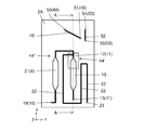
- FIG. 11 to 13 schematically show a part of the measuring device 1A of another example.
- FIG. 11 is a top view of the measuring device 1A as viewed from above.
- FIG. 12 is a sectional view of the measuring apparatus 1A, and is a sectional view in the case where the measuring apparatus 1A is cut along the line AA shown in FIG.
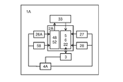
- FIG. 13 is a conceptual diagram of the measuring apparatus 1A, and shows the relationship of each constituent element by a block diagram. Note that, also in these drawings, the illustration of the mechanism for rotationally driving the optical sensor is omitted.
- the measuring device 1A further includes a separation channel device 33 arranged on the upper surface of the channel device 2A.
- the separation flow path device 33 is a flow path for separating and extracting specific particles to be measured from the sample, and selecting the particles. Since the measuring device 1A includes the flow channel device 2A and the separation flow channel device 33, the particles to be measured can be separated and sorted from the sample in a continuous process, thus improving work efficiency. Can be made In the following description of this example, the flow channel device 2A is referred to as "measuring flow channel device 2A".
- FIG. 14 is a top view of the separation channel device 33 when seen through from above.
- FIG. 15 is an enlarged view of the broken line portion in FIG.
- the separation channel device 33 can separate and collect particles contained in a liquid so that the particles can be taken out from the sample.
- the separation channel device 33 has a fourth channel 34. This allows the particles to be separated and collected.
- the separation channel device 33 is, for example, a plate-shaped member. Further, the planar shape of the separation channel device 33 is, for example, a rectangular shape, and the surface is a flat surface. The thickness of the separation channel device 33 may be, for example, 1 to 5 mm. The planar shape of the separation channel device 33 may be, for example, 10 to 30 mm on the short side and 10 to 50 mm on the long side.
- the separation channel device 33 can be formed by injection molding, for example.
- the separation channel device 33 is mainly formed by the third substrate 35 and the fourth substrate 36.
- the separation flow path device 33 has a third substrate 35 having a groove and a fourth substrate 36 arranged on the surface of the third substrate 35.
- the fourth substrate 36 closes the opening of the groove of the third substrate 35. That is, the groove of the third substrate 35 and the surface of the fourth substrate 36 form the fourth flow path 34.
- the separation channel device 33 may have members other than the third substrate 35 and the fourth substrate 36.
- the third substrate 35 and the fourth substrate 36 are flat members, for example.
- the material of the third substrate 35 and the fourth substrate 36 may be, for example, glass, acrylic resin, polycarbonate resin, polydimethylsiloxane (PDMS) resin, or the like.
- the material of the third substrate 35 and the fourth substrate 36 in this example is PDMS.
- the third substrate 35 or the fourth substrate 36 may be located on the upper side, in the separation channel device 33 of this example, the third substrate 35 is arranged on the upper surface of the fourth substrate 36. ing.
- the fourth flow path 34 has a fourth main flow path 37 and a fourth branch flow path 38 branched from the fourth main flow path 37.
- the liquid flowing in the separation channel device 33 flows into the fourth main channel 37 and is a particle different from the specific particle (first particle P1) to be measured.
- Only the (second particles P2) flow from the fourth main channel 37 into the fourth branch channel 38 to separate and collect the specific particles, and the separated specific particles (first particles P1) are used as the sample. It can be included and collected. It is also possible to separate and collect different particles (second particles P2) on the side of the fourth branch flow channel 38 by causing only different particles to flow into the fourth branch flow channel 38.
- the fourth branch flow path 38 is designed so that only the second particles P2 branch, but it is not always the case that only the second particles P2 branch. That is, particles different from the second particles P2 may flow into the fourth branch flow path 38.
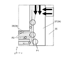
- FIG. 15 schematically shows how the first particles P1 and the second particles P2 are separated.
- the large circle in the figure indicates the first particle P1 and the small circle indicates the second particle P2.
- the thick arrow along the X-axis direction is the main flow, and the thick arrow along the Y-axis direction indicates the “pressing flow” described later. Further, the hatched area in the drawing indicates a "pull-in flow” described later.
- the fourth flow path 34 of this example has one fourth main flow path 37 and a plurality of fourth branch flow paths 38 connected to one side of one fourth main flow path 37.
- the fourth main flow path 37 and the fourth branch flow path 38 are adjusted to have a fourth cross section in the fourth main flow path 37 by adjusting the cross-sectional areas and lengths of the fourth main flow path 37 and the flow velocity of the sample.
- a “pull-in flow” that flows from the main flow path 37 to the fourth branch flow path 38 can be generated.
- a pressing flow capable of pressing the sample flowing in the fourth main channel 37 to the fourth branch channel 38 side is generated in the fourth channel 34. As a result, as shown in FIG.
- the width of the drawing flow is larger than the center of gravity of a predetermined particle (second particle P2) flowing in the sample, and the center of gravity of another particle (first particle P1).
- predetermined particles second particles P2 can be drawn into the fourth branch flow channel 38.
- the separation channel device 33 of this example is particularly intended to separate red blood cells (second particles P2) and white blood cells (first particles P1) in blood.
- the center of gravity of red blood cells in blood is, for example, a position of 2 to 2.5 ⁇ m from the edge, and the center of gravity of white blood cells is, for example, a position of 5 to 10 ⁇ m from the edge.
- the fourth main flow path 37 may have a cross-sectional area of 300 to 1000 ⁇ m 2 and a length of 0.5 to 20 mm, for example.
- the fourth branch flow channel 38 may have a cross-sectional area of 100 to 500 ⁇ m 2 and a length of 3 to 25 mm, for example.
- the flow velocity in the fourth flow path 34 may be, for example, 0.2 to 5 m / s.
- the width of the drawing flow can be set to, for example, 2 to 15 ⁇ m, and the red blood cells as the second particles P2 and the white blood cells as the first particles P1 can be separated from the blood.
- the fourth flow path 34 further has a fourth recovery flow path 39 connected to the fourth main flow path 37, and can recover the first particles P1.
- the pressing flow can be used to collect the first particles P1 in the fourth recovery flow path 39.
- the fourth flow path 34 may have a fourth waste flow path 40 connected to the plurality of fourth branch flow paths 38.
- the separated second particles P2 may be collected or discarded by the fourth disposal flow channel 40.
- one fourth waste channel 40 connected to the plurality of fourth branch channels 38 collects the first particles P1. Functions as a flow path. Further, in this case, the liquid that has completely flowed through the fourth main flow path 37 may be discarded.
- the fourth flow path 34 has a plurality of fourth openings 41 located on the surface of the separation flow path device 33.
- the plurality of fourth openings 41 includes at least a fourth sample inlet 42 through which the sample flows into the fourth main channel 37, a fourth sample outlet 43 for collecting the first particles from the fourth recovery channel 39, and a sample from the sample. And at least one fourth waste outlet 44 for collecting components other than the first particles.
- the fourth waste outlet 44 is connected to the fourth main passage 37 and the fourth waste passage 40.
- the liquid flowing out from the fourth waste outflow port 44 is recovered via a through hole 44 'formed in the second flow path device 2A described later.
- the fourth sample outlet 43 is connected to the first inlet 12 of the first channel 5 of the measurement channel device 2A.
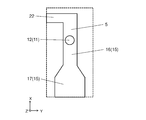
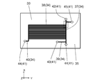
- FIG. 16 schematically shows the measurement channel device 2A.
- FIG. 16 is a top view of the measurement flow channel device 2A seen through from above.
- the upper surface of the measurement flow channel device 2A of this example has a first region 46 in which the separation flow channel device 33 is arranged and a second region 47 which does not overlap with the first region 46. ..
- the first channel 5 of the measurement channel device 2A is arranged from the first region 46 to the second region 47, and the separation channel device 33 is the same as that of the measurement channel device 2A. It is arranged only in the first area 46. Thereby, since the first flow path 5 is exposed in the second region 47, the second region 47 can be used as a measurement region (measurement region 105 and comparison region 106).
- the reflecting member 24 is arranged in the second region 47.
- the measurement flow channel device 2A may further include a fifth flow channel 48, which is different from the first flow channel 5, the second flow channel 6, and the third flow channel 22.
- the fifth flow path 48 may have a plurality of fifth openings 49 located on the surface of the measurement flow path device 2A.
- the fifth channel 48 can function as a channel through which the sample before particle separation flows.
- the plurality of fifth openings 49 have a fifth inflow port 50 and a fifth outflow port 51.
- the fifth inflow port 50 is an opening for the sample to flow into the fifth flow path 48.
- the fifth outflow port 51 is an opening for the sample to flow out from the fifth flow path 48.
- the fifth inflow port 50 is exposed, and the fifth outflow port 51 is connected to the fourth sample inflow port 42 of the separation channel device 33.
- the fifth inlet 50 and the fifth outlet 51 are located on the upper surface of the measurement flow path device 2A (the upper surface of the first substrate 9).
- the fifth inlet 50 is located on the same plane as the first inlet 12.
- the fifth outlet 51 is located on the same surface as the first inlet 12.
- the fifth inlets 50 of the plurality of fifth openings 49 and the third opening 23 are located on the same surface.
- the measurement flow channel device 2A may further include a sixth flow channel 52, which is different from the first flow channel 5, the second flow channel 6, the third flow channel 22, and the fifth flow channel 48.
- the sixth channel 52 has a plurality of sixth openings 53 located on the surface of the measurement channel device 2A.
- the plurality of sixth openings 53 have sixth inlets 54 and sixth outlets 55.
- the sixth inlet 54 is an opening through which the third liquid for the pressing flow in the separation channel device 33 flows into the sixth channel 52.
- the sixth outflow port 55 is an opening through which the third liquid flows out of the sixth flow path 52.
- the sixth inflow port 54 is exposed, and the sixth outflow port 55 is connected to the fourth pressing inflow port 45 of the separation channel device 33.
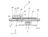
- FIG. 17 schematically shows the connection structure of the separation channel device and the measurement channel device. Note that FIG. 17 is an enlarged cross-sectional view of the broken line portion in FIG.
- the separation channel device 33 is arranged on the upper surface of the measurement channel device 2A as described above. Specifically, the sheet member 56 may be interposed between the lower surface of the separation channel device 33 and the upper surface of the measurement channel device 2A. In other words, the measuring device 1 may have the sheet member 56 arranged between the separation channel device 33 and the measurement channel device 2A.
- the sheet member 56 has a function as an intermediate layer for joining difficult-to-bond materials.
- the sheet member 56 may be made of a material such as silicone or PDMS.
- the sheet member 56 has a plurality of through holes 57. The liquid flows through the through hole 57 between the separation channel device 33 and the measurement channel device 2A.
- the separation channel device 33 and the measurement channel device 2A of this example are connected via an adhesive applied to the lower surface of the sheet member 56.
- the measuring apparatus 1A of the present example further includes a first pump 26A that supplies the first liquid to the fifth flow path 48 and a fourth pump 58 that supplies the third liquid to the sixth flow path 52.
- the first pump 26A corresponds to the first pump 26 in the above example. That is, the first pump 26A supplies the first liquid to the first flow path 5 through the fifth flow path 48 and the fourth flow path 34 in this order.
- the first pump 26A, the second pump 27, the third pump 28, and the fourth pump 58 each have a fifth opening 49, a second opening 18, and a plurality of other flow paths (not shown) such as tubes. It communicates with the third opening 23 and the sixth opening 53.
- the control unit 4A can control the measuring device 1A. Specifically, the control unit 4A can also control driving of the optical sensor 3, the first pump 26A, the second pump 27, the third pump 28, the fourth pump 58, and the like.
- the control unit 4A can drive the first pump 26A to cause the liquid containing the specific particles to flow into the first flow path 5 as the first liquid. Further, the control unit 4A can drive the second pump 27 to cause the liquid not containing the specific particles to flow into the second flow path 6 as the second liquid.
- the control unit 4A can drive the third pump 28 to cause gas (gas) to flow into the third flow path 22. Further, the control unit 4A can also control the operation of the rotary drive actuator 102 (not shown).
- the control unit 4A is configured by combining various circuits.
- the control unit 4A may cause the sample to flow into the fourth main channel 37 of the fourth channel 34 after the third liquid has flowed into the fourth main channel 37 of the fourth channel 34.
- the control unit 4A may drive the fourth pump 58 to cause the third liquid to flow into the fourth main channel 37, and then drive the first pump 26 to cause the sample to flow into the fourth main channel 37.
- one end of the second flow path 6 has been described as having the second outlet 20, but as shown in FIG. 18, one end of the second flow path 6 is the first flow path. 5 may be connected.
- the second flow path 6 When the second flow path 6 is connected to the first flow path 5, the second liquid can flow into the first flow path 5 via the second flow path 6.
- the second liquid when the amount of the first liquid flowing into the first flow path 5 is small, the second liquid can be replenished from the second flow path 6 to the first flow path 5.
- the second liquid may be the same liquid as the third liquid.
- the control unit 4 allows the first liquid to reach the first flow path 5 with a constant amount before the first liquid reaches the first flow path 5.
- the second liquid may be introduced. As a result, it is possible to quantitatively measure how many particles are contained in a certain amount of solvent (first liquid).
- the control unit 4 may check the presence or absence of the liquid by the optical sensor 3 when the second liquid is caused to flow into the first flow path 5. In this case, the control unit 4 drives the second pump 27 to cause the second liquid to flow into the second flow path 6 and then drives the optical sensor 3, and at the same time, drives the first pump 26 (or the first pump 26). The pump 26A and the fourth pump 58) may be driven to flow the first liquid into the first flow path 5 (and the liquid into the sixth flow path 52). Further, the control unit 4 may drive the second pump 27 within a certain time after driving the first pump 26 (or the first pump 26A and the fourth pump 58).
- the third flow path 22 may be connected to the connecting portion between the first flow path 5 and the second flow path 6.
- the control unit 4 first causes the second liquid to flow into the first flow path 5, then causes the first liquid to flow into the first flow path 5, and then supplies the gas to the first flow path 5. It is good to let it flow in. Thereby, it is possible to reduce the inflow of the first liquid into the second flow path 6.
- the gas may be caused to flow into the first flow path 5 to divide the second liquid existing from the second flow path 6 to the first flow path 5, and then the first liquid may be flowed in.
- the control unit 4 may drive the second pump 27, then the third pump 28, and then the first pump 26.
- the third liquid is supplied from the sixth flow channel 52 to the fourth flow channel 34
- the third liquid is supplied from the second flow channel 6.
- the second liquid and the third liquid are the same liquid. That is, the sixth flow path 52 does not exist, and one end of the second flow path 6 is connected to the fourth pressing inlet 45 of the fourth flow path 34.
- the sheet member 56 is used as the fourth substrate 36 instead of the fourth substrate 36. It may function.
Abstract
A measuring device of the present disclosure is provided with: a flow passage device having a first flow passage through which a first liquid including particles to be measured flows and which has a measurement region measured by an optical sensor, a second flow passage through which a second liquid to be compared flows and which has a comparative region comparatively measured by an optical sensor, and a correction region of the optical sensor; an arm-like member having a first end on which the optical sensor is arranged, and a second end on which a driving shaft is arranged; and a rotation drive actuator for rotationally driving the arm-like member within a predetermined range, wherein the measurement region, the comparative region, and the correction region are each arranged as a region including a cylindrical position to which the optical sensor moves according to the rotary operation of the arm-like member.
Description
本開示は、計測対象の粒子を含む液体と比較対象の液体とをそれぞれ流路に流して光学センサで計測する計測装置に関する。
The present disclosure relates to a measuring device that causes a liquid containing a particle to be measured and a liquid to be compared to flow in respective flow channels to measure with an optical sensor.
計測対象の粒子を含む液体、例えば白血球などを含む血液などの液体と、その粒子を含まない比較対象である液体、例えば較正のための生理食塩水などの液体とを、いわゆるマイクロ流路を有する反応装置またはマイクロチップに供給して、計測対象の粒子を含む液体について種々の計測を行なうことが知られている(例えば、特開2001-74724号公報および国際公開第2009/145022号を参照)。またその粒子の計測として、発光素子および受光素子を有する光学センサを用いて、計測対象の粒子の濃度などを計測することも知られている。
A liquid containing particles to be measured, for example, a liquid such as blood containing white blood cells and the like, and a liquid to be compared not containing the particles, for example, a liquid such as physiological saline for calibration have a so-called micro flow path. It is known that various measurements are performed on a liquid containing particles to be measured by supplying it to a reaction device or a microchip (see, for example, Japanese Patent Application Laid-Open No. 2001-74724 and International Publication No. 2009/145022). .. It is also known to measure the concentration of particles to be measured using an optical sensor having a light emitting element and a light receiving element as the measurement of the particles.
本開示の計測装置は、計測対象の粒子を含む第1液体が流されるとともに該第1液体中の前記粒子を光学センサで計測する計測領域を有する第1流路、前記粒子を含まない比較対象の第2液体が流されるとともに該第2液体を前記光学センサで比較計測する比較領域を有する第2流路、および前記光学センサの較正のための較正領域を有する流路デバイスと、発光素子および受光素子を有する前記光学センサが第1端に配置され、第2端に駆動軸が配置されているアーム状部材と、前記駆動軸に接続され、前記アーム状部材を所定の範囲内で回転駆動する回転駆動用アクチュエータとを備えており、前記計測領域、前記比較領域および前記較正領域は、それぞれ前記アーム状部材の回転駆動に伴って前記光学センサが動く円周状の位置を含む領域として配置されている。
The measuring device of the present disclosure includes a first flow path having a measurement region in which a first liquid containing particles to be measured is caused to flow and the particles in the first liquid are measured by an optical sensor, a comparison target not containing the particles. A second flow path having a comparison area for comparing and measuring the second liquid with the optical sensor, and a flow path device having a calibration area for calibrating the optical sensor; a light emitting element; The optical sensor having a light receiving element is arranged at a first end and a drive shaft is arranged at a second end, and an arm-shaped member connected to the drive shaft to drive the arm-shaped member to rotate within a predetermined range. The measurement area, the comparison area, and the calibration area each include a circumferential position at which the optical sensor moves as the arm member is driven to rotate. It is disposed as a region.
計測対象の粒子を含む液体および比較対象の液体を光学センサで計測するには、それぞれの液体をマイクロ流路などの流路に流して、その流路の所定の領域において計測することが行なわれる。その際、両方の流路に対して、それぞれ光学センサを配置して同時に計測したり、1つの光学センサで順に計測したりすることが行なわれる。
In order to measure a liquid containing particles to be measured and a liquid to be compared with an optical sensor, each liquid is caused to flow through a flow path such as a micro flow path, and measurement is performed in a predetermined region of the flow path. .. At that time, an optical sensor is arranged for each of the two flow paths to perform simultaneous measurement, or one optical sensor performs sequential measurement.
しかしながら、複数の光学センサを用いてそれぞれの流路に対して配置する場合には、計測装置の小型化が困難になる傾向があり、また、光学センサ間の特性のばらつきあるいは劣化を補正して精度よく計測することが困難になる傾向があった。一方、両方の流路の所定領域に対して1つの光学センサを用いて、光学センサを移動させて順に計測する場合には、光学センサの特性のばらつきあるいは劣化の影響は低減されるものの、移動機構の小型化を図りつつ各領域に対応させて速やかにかつ精度よく移動させることが困難になる傾向があった。
However, when using a plurality of optical sensors and arranging them for each flow path, it tends to be difficult to reduce the size of the measuring device, and it is necessary to correct the variation or deterioration of the characteristics between the optical sensors. It tends to be difficult to measure accurately. On the other hand, when one optical sensor is used for a predetermined region of both flow paths and the optical sensors are moved and sequentially measured, the effect of variation or deterioration in the characteristics of the optical sensor is reduced, but the movement is reduced. There is a tendency that it is difficult to move the mechanism quickly and accurately in correspondence with each area while reducing the size of the mechanism.
そこで、計測領域を有する流路と比較領域を有する流路とを有する流路デバイスに対して、光学センサによって精度よく安定した計測を行なうことができる実用的な手段が求められている。
Therefore, there is a demand for a practical means capable of performing accurate and stable measurement with an optical sensor for a flow channel device having a flow channel having a measurement region and a flow channel having a comparison region.
本開示の計測装置によれば、計測対象の粒子を含む第1液体が流され、計測領域を有する第1流路と、粒子を含まない比較対象の第2液体が流され、比較領域を有する第2流路とを有する流路デバイスに対して、発光素子および受光素子を有する光学センサが第1端に配置され、回転駆動用アクチュエータが接続された駆動軸が第2端に配置されているアーム状部材を用い、このアーム状部材の回転駆動に伴って光学センサが動く円周状の位置に計測領域および比較領域が配置されていることから、計測装置の小型化を図りつつ精度よくかつ安定した計測を行なうことができる。また、流路デバイスには、光学センサが動く円周状の位置に較正領域が配置されていることから、計測に際して必要に応じて光学センサの較正を行なうことができるので、光学センサの特性のばらつきあるいは劣化の影響を低減して、精度よく安定した計測を行なうことができる。
According to the measurement device of the present disclosure, the first liquid containing the particles to be measured is flowed, and the first flow path having the measurement region and the second liquid to be compared containing no particles are flowed to have the comparison region. An optical sensor having a light emitting element and a light receiving element is arranged at a first end, and a drive shaft to which a rotation driving actuator is connected is arranged at a second end with respect to a flow path device having a second flow path. Since the measurement area and the comparison area are arranged at the circumferential position where the optical sensor moves in accordance with the rotation driving of the arm-shaped member, the measurement device can be downsized accurately and accurately. Stable measurement can be performed. In addition, since the flow path device has the calibration region arranged at the circumferential position where the optical sensor moves, the optical sensor can be calibrated as necessary during measurement. Accurate and stable measurement can be performed by reducing the influence of variation or deterioration.
以下、本開示の計測装置の実施形態の例について、またこの計測装置における流路デバイスの例について、図面を参照しつつ説明する。本開示では、便宜的に直交座標系(X,Y,Z)を定義してZ軸方向の正側を上方とするが、本開示においては、いずれの方向が上方または下方とされてもよい。以下の内容は本開示の実施形態を例示するものであって、本開示はこれらの実施形態に限定されるものではない。本開示の要旨を逸脱しない範囲で、種々の変更を加えても差し支えないことは言うまでもない。
Hereinafter, an example of an embodiment of a measuring device of the present disclosure and an example of a flow channel device in this measuring device will be described with reference to the drawings. In the present disclosure, an orthogonal coordinate system (X, Y, Z) is defined for convenience, and the positive side in the Z-axis direction is the upper side, but in the present disclosure, any direction may be the upper side or the lower side. .. The following contents exemplify the embodiments of the present disclosure, and the present disclosure is not limited to these embodiments. It goes without saying that various modifications may be made without departing from the scope of the present disclosure.
図1は、本開示の計測装置の実施形態の例を示す図であり、図1(a)は上面図であり、図1(b)は側面図である。なお、図1(a)においては、一部を透視して示すとともに、動作を説明するために他の一部を重複して示している。
1A and 1B are diagrams showing an example of an embodiment of a measuring device of the present disclosure, FIG. 1A is a top view, and FIG. 1B is a side view. In addition, in FIG. 1A, a part is shown in a see-through manner, and the other part is shown in duplicate for the purpose of explaining the operation.
本例の計測装置1は、検査対象である第1液体および比較対象である第2液体をそれぞれ検査用デバイス(図示せず)の第1流入口および第2流入口に供給するためのものである。計測装置1は、計測対象の粒子を含む第1液体が流されるとともにこの第1液体中の粒子を光学センサ3で計測する計測領域105を有する第1流路5、粒子を含まない比較対象の第2液体が流されるとともにこの第2液体を光学センサ3で比較計測する比較領域106を有する第2流路6、および光学センサ3の較正のための較正領域107を有する流路デバイス2を備えている。また、発光素子および受光素子を有する光学センサ3が第1端(図における左側の端)に配置され、第2端(図における右側の端)に駆動軸101が配置されているアーム状部材100を備えている。また、駆動軸101に接続され、アーム状部材100を所定の範囲内で回転駆動する回転駆動用アクチュエータ102を備えている。そして、流路デバイス2における計測領域105、比較領域106および較正領域107は、それぞれアーム状部材100の回転駆動に伴って光学センサ3が動く円周状の位置(図1(a)中に仮想的に一点鎖線で示す。)を含む領域として配置されている。
The measuring apparatus 1 of this example is for supplying the first liquid to be inspected and the second liquid to be compared to the first inflow port and the second inflow port of the inspection device (not shown), respectively. is there. The measuring apparatus 1 includes a first flow path 5 having a measurement region 105 in which a first liquid containing particles to be measured is caused to flow and particles in the first liquid are measured by the optical sensor 3, a comparison target not containing particles. A second channel 6 having a comparison region 106 through which the second liquid flows and the second sensor compares and measures the second liquid, and a channel device 2 having a calibration region 107 for calibrating the optical sensor 3. ing. Further, the optical sensor 3 having the light emitting element and the light receiving element is arranged at the first end (the left end in the drawing), and the drive shaft 101 is arranged at the second end (the right end in the drawing). Is equipped with. Further, it is provided with a rotary drive actuator 102 which is connected to the drive shaft 101 and rotationally drives the arm member 100 within a predetermined range. The measurement area 105, the comparison area 106, and the calibration area 107 in the flow path device 2 are arranged in a circumferential position (virtual in FIG. 1A) where the optical sensor 3 moves as the arm member 100 is rotationally driven. Is indicated by a one-dot chain line).
なお、図1(a)および(b)において、流路デバイス2の内部に位置する計測領域105(第1流路5)および比較領域106(第2流路6)ならびに較正領域107(図1(b)では図示を省略)の位置は、それぞれ破線で示している。また、図1(a)において、光学センサ3およびアーム状部材100は、流路デバイス2を透視して示しているとともに、光学センサ3が各領域105,106,107に対向する場合を重複して3か所に位置するように示し、破線の両矢印の円弧でその動きを示している。
1A and 1B, the measurement area 105 (first flow path 5), the comparison area 106 (second flow path 6) and the calibration area 107 (FIG. 1) located inside the flow path device 2 are shown. The positions of (b) are omitted in the drawing). In addition, in FIG. 1A, the optical sensor 3 and the arm-shaped member 100 are shown by seeing through the flow path device 2, and the case where the optical sensor 3 faces each of the regions 105, 106, 107 overlaps. Are shown to be located at three positions, and their movements are indicated by the arcs of the double-headed arrow with broken lines.
このような本例の計測装置1によれば、駆動軸101に回転駆動用アクチュエータ102が接続されたアーム状部材100によって、光学センサ3を所定の範囲内(駆動軸101を回転中心とした円周上の範囲)で回転駆動するとともに、計測領域105および比較領域106が、アーム状部材100の回転駆動に伴って光学センサ3が動く円周状の位置を含む領域として配置されていることによって、計測領域105での計測と比較領域106での比較計測とをアーム状部材100のわずかな動きで順に行なうことが可能となる。これにより、簡便に精度よく計測が行なえるとともに、光学センサ3の駆動機構が大掛かりなものにならず、計測装置1の小型化を図ることができる。また、光学センサ3の較正に使用する較正領域107も、同様に光学センサ3が動く円周状の位置を含む領域として配置されているので、計測毎に測定上のゼロ点として光学センサ3の特性を較正することができ、光学センサ3の特性の変動による影響を低減して、安定して精度よく計測を行なうことができる。また、光学センサ3による計測領域105での計測、比較領域106での比較計測、および較正領域107での較正を、所望の順序で容易に行なうことができる。
According to the measuring device 1 of the present example as described above, the optical sensor 3 is within a predetermined range (a circle with the drive shaft 101 as the center of rotation) by the arm-shaped member 100 in which the rotary drive actuator 102 is connected to the drive shaft 101. While being driven to rotate in a circumferential range), the measurement region 105 and the comparison region 106 are arranged as a region including a circumferential position where the optical sensor 3 moves as the arm member 100 is driven to rotate. The measurement in the measurement region 105 and the comparison measurement in the comparison region 106 can be sequentially performed with a slight movement of the arm-shaped member 100. As a result, the measurement can be easily and accurately performed, and the driving mechanism of the optical sensor 3 does not become large, so that the measuring device 1 can be downsized. Further, since the calibration area 107 used for the calibration of the optical sensor 3 is also arranged as an area including the circumferential position where the optical sensor 3 moves, the calibration area 107 of the optical sensor 3 is set as a zero point on each measurement. The characteristic can be calibrated, the influence of the variation of the characteristic of the optical sensor 3 can be reduced, and stable and accurate measurement can be performed. Further, the measurement in the measurement region 105 by the optical sensor 3, the comparison measurement in the comparison region 106, and the calibration in the calibration region 107 can be easily performed in a desired order.
本開示の計測装置1は、第1液体として例えば血液を用いて、第1液体中の計測対象の粒子として例えば白血球等の細胞を扱うことにより、光学センサ3によってその粒子の濃度を光学的に計測することができるものであり、粒子濃度計測装置として機能するものである。第1液体として血液を用いる場合には、粒子を含まない第2液体としては、例えば生理食塩水(リン酸緩衝生理食塩水、Phosphate Buffered Salts:PBS)を用いることができる。なお、計測対象である粒子としては、他にも種々の無機物あるいは有機物からなる粒子にも適用することができ、いずれも適当な媒質である第1液体および第2液体を用いることができる。これにより、本開示の計測装置1は、第1液体中の種々の粒子の濃度を光学的に計測することができる粒子濃度計測装置として機能する。
The measuring device 1 of the present disclosure uses, for example, blood as the first liquid, and handles cells such as white blood cells as particles to be measured in the first liquid, so that the optical sensor 3 optically determines the concentration of the particles. It can be measured and functions as a particle concentration measuring device. When blood is used as the first liquid, physiological saline (Phosphate Buffered Salts: PBS) can be used as the second liquid that does not contain particles, for example. As the particles to be measured, other particles made of various inorganic or organic substances can be applied, and the first liquid and the second liquid, which are suitable media, can be used for both of them. Thereby, the measuring device 1 of the present disclosure functions as a particle concentration measuring device capable of optically measuring the concentrations of various particles in the first liquid.
流路デバイス2の例における構成については、詳しくは後述するが、基本的な構成として、流路デバイス2の上面側から第1液体および第2液体が供給され、計測を終えた液体は流路デバイス2の下面側から排出されて回収あるいは廃棄される。従って、光学センサ3は流路デバイス2の下面側に配置されることとなる。しかしながら、第1液体および第2液体の供給および排出は流路デバイス2の上面側および下面側のどちら側から行なってもよいので、流路デバイス2の構成に応じて、光学センサ3を流路デバイス2の上面側に配置してもよい。
The configuration in the example of the flow channel device 2 will be described in detail later, but as a basic configuration, the first liquid and the second liquid are supplied from the upper surface side of the flow channel device 2, and the liquid for which measurement has been completed is the flow channel. It is discharged from the lower surface side of the device 2 and collected or discarded. Therefore, the optical sensor 3 is arranged on the lower surface side of the flow path device 2. However, since the supply and discharge of the first liquid and the second liquid may be performed from either the upper surface side or the lower surface side of the flow channel device 2, the optical sensor 3 may be connected to the flow channel device 2 depending on the configuration of the flow channel device 2. It may be arranged on the upper surface side of the device 2.
流路デバイス2は、計測領域105および比較領域106において第1液体および第2液体に対する光学的な測定を行なうため、少なくともこれらの領域は透光性であるが、その他の部分については、透光性であっても非透光性であってもよい。
Since the flow channel device 2 performs optical measurement on the first liquid and the second liquid in the measurement region 105 and the comparison region 106, at least these regions are translucent, but other parts are translucent. It may be transparent or non-translucent.
なお、較正領域107については、必ずしも計測領域105および比較領域106を有する流路デバイス2の基板に一体に配置されている必要はない。例えば、計測に当たって流路デバイス2をセットするステージ(図示せず)の一部を、セットすることによって一体的に流路デバイス2を構成する部材としておき、この流路デバイス2を構成する部材に較正領域107を配置しておくようにしてもよい。これによれば、複数の第1液体の交換に伴って複数の流路デバイス2を交換する場合にも、同じ較正領域107によって同じ基準での光学センサ3の較正を行なうことができ、精度よく安定した計測を行なう上で有利となる。また、較正領域107は光学的測定の基準(ゼロ点)として機能するものであるので、較正領域107を流路デバイス2の基板に一体に配置した場合には、複数の流路デバイス2を交換する場合に、常に新規な基準として機能させることができ、例えば計測の対象物の特性が変わる場合に、その特性に応じた基準として較正領域107の特性を設定することができ、多様な計測に対応できるものとすることができる。
Note that the calibration area 107 does not necessarily have to be integrally arranged on the substrate of the flow path device 2 having the measurement area 105 and the comparison area 106. For example, a part of a stage (not shown) for setting the flow channel device 2 for measurement is set as a member that integrally configures the flow channel device 2, and the member that configures the flow channel device 2 is set. The calibration area 107 may be arranged. According to this, even when the plurality of flow path devices 2 are replaced with the replacement of the plurality of first liquids, it is possible to calibrate the optical sensor 3 with the same reference by the same calibration region 107, and it is possible to accurately perform the calibration. This is advantageous for stable measurement. Further, since the calibration area 107 functions as a reference (zero point) for optical measurement, when the calibration area 107 is integrally arranged on the substrate of the flow channel device 2, a plurality of flow channel devices 2 are replaced. In this case, the characteristics of the calibration region 107 can be set as a reference according to the characteristics of the measurement object, for example, when the characteristics of the measurement object change, and thus various measurements can be performed. Can be adapted.
光学センサ3は、発光素子および受光素子を有しており、発光素子から発した光を第1液体が存在する計測領域105、第2液体が存在する比較領域106、および較正領域107に照射し、それぞれの領域から反射してくる反射光を受光素子で受光することにより、その出力電流を検出することによって対象物の光学的な計測を行なうことができる。
The optical sensor 3 has a light emitting element and a light receiving element, and irradiates the light emitted from the light emitting element to the measurement region 105 in which the first liquid is present, the comparison region 106 in which the second liquid is present, and the calibration region 107. By receiving the reflected light reflected from each of the regions by the light receiving element, the output current thereof can be detected to optically measure the object.
アーム状部材100は、回転駆動用アクチュエータ102によって回転駆動されて、駆動軸101を中心とした円周状に光学センサ3を移動させるものである。アーム状部材100の形状および大きさは、流路デバイス2の構成に応じて、また光学センサ3の移動に際して所望の強度および精度が確保できるように、適宜設定すればよい。また、アーム状部材100の材質についても、所望の強度、精度および耐久性が確保できるものであれば、各種の樹脂、金属、ガラス、セラミックスなど、種々の材料を選択できる。アーム状部材100は、全体を1つの部材として構成するものに限られず、各部のパーツに分けて適宜組み合わせて構成してもよい。
The arm-shaped member 100 is rotationally driven by the rotational driving actuator 102, and moves the optical sensor 3 in a circumferential shape around the drive shaft 101. The shape and size of the arm-shaped member 100 may be appropriately set according to the configuration of the flow path device 2 and so that desired strength and accuracy can be secured when the optical sensor 3 moves. As for the material of the arm-shaped member 100, various materials such as various resins, metals, glass, and ceramics can be selected as long as desired strength, accuracy, and durability can be secured. The arm-shaped member 100 is not limited to one configured as a single member as a whole, but may be configured by appropriately combining parts of each part.
駆動軸101は、回転駆動用アクチュエータ102の回転駆動軸とアーム状部材100の第2端とに接続されて、アーム状部材100を所望の回転角および速度で回転駆動する中心点として機能する。
The drive shaft 101 is connected to the rotary drive shaft of the rotary drive actuator 102 and the second end of the arm-shaped member 100, and functions as a center point for rotationally driving the arm-shaped member 100 at a desired rotation angle and speed.
回転駆動用アクチュエータ102は、アーム状部材100を所定の位置に精度よく回転駆動できるものであれば種々の駆動手段を用いることができる。例えば、パルスモータ(ステッピングモータともいう)、サーボモータなどの各種モータを駆動軸101への直結あるいはギヤ機構を介して接続すればよいのはもとより、スライダクランク機構あるいは直線運動を回転運動に変換するラック&ピニオンのようなギヤ機構を備えたシリンジ(ピストン)、ピエゾアクチュエータまたはリニアモータなど、本開示におけるアーム状部材100の回転駆動を行なえるものであれば特に制約はない。
As the rotation driving actuator 102, various driving means can be used as long as the arm-shaped member 100 can be accurately driven to rotate at a predetermined position. For example, various motors such as a pulse motor (also referred to as a stepping motor) and a servo motor may be directly connected to the drive shaft 101 or connected via a gear mechanism, and of course, a slider crank mechanism or a linear motion is converted into a rotary motion. There is no particular limitation as long as it can rotate and drive the arm-shaped member 100 in the present disclosure, such as a syringe (piston) having a gear mechanism such as a rack and pinion, a piezo actuator, or a linear motor.
中でも、回転駆動用アクチュエータ102には、パルスモータを用いることが好ましい。パルスモータによる回転駆動は、制御が用意で、低速で高トルクによる回転駆動ができ、位置決め精度も良好であるので、本開示における光学センサ3の移動についての駆動手段として好適である。また、光学センサ3による光学的測定をするためには、各領域において光学センサ3の位置決めをして、かつその場において静止状態で保持することが重要であるが、そのような特性においてもパルスモータは好適である。
Above all, it is preferable to use a pulse motor for the rotary drive actuator 102. Rotational drive by a pulse motor is suitable as a drive unit for moving the optical sensor 3 in the present disclosure because it is easy to control, can be rotationally driven by high torque at low speed, and has good positioning accuracy. Further, in order to perform the optical measurement by the optical sensor 3, it is important to position the optical sensor 3 in each region and hold the optical sensor 3 in a stationary state in that area. Motors are preferred.
なお、図示は省略しているが、本開示の計測装置1は、光学センサ3における発光素子に電力を供給して発光させるための電源部、受光素子からの出力電流が入力されて所定の演算処理をするための処理部、および回転駆動用アクチュエータ102に所望の回転駆動を行なわせるための駆動制御部などを有する制御部も備える。これら各部には、公知の種々の回路または装置などを適用することができる。
Although illustration is omitted, in the measurement device 1 of the present disclosure, a predetermined calculation is performed by inputting an output current from a power supply unit for supplying electric power to the light emitting element in the optical sensor 3 to cause the light emitting element to emit light. It also includes a processing unit for performing processing, and a control unit having a drive control unit for causing the rotation driving actuator 102 to perform desired rotation driving. Various known circuits or devices can be applied to each of these parts.
本開示の計測装置1において、図1(b)に示すように、流路デバイス2は、計測領域105および比較領域106に対応して光学センサ3の反対側、本例では上面側に配置された反射部材24または非反射部材24を有していることが好ましい。反射部材24は、光学センサ3の発光素子が出射した光のうち、計測領域105の第1流路5および比較領域106の第2流路6のそれぞれを通過した光を、光学センサ3の受光素子へ反射することができる。また、非反射部材24は、光損失の測定において計測領域105の第1流路5および比較領域106の第2流路6のそれぞれを通過した光にDCオフセットの成分が多い場合に、その光の反射を防ぎ、また外乱光の入射を防ぐことができる。
In the measurement device 1 of the present disclosure, as shown in FIG. 1B, the flow path device 2 is arranged on the opposite side of the optical sensor 3, that is, on the upper surface side in this example, corresponding to the measurement region 105 and the comparison region 106. It is preferable to have a reflective member 24 or a non-reflective member 24. The reflecting member 24 receives the light emitted from the light emitting element of the optical sensor 3 that has passed through each of the first flow path 5 of the measurement region 105 and the second flow path 6 of the comparison region 106, and receives the light of the optical sensor 3. Can be reflected to the element. Further, the non-reflective member 24 is configured to measure the light loss when the light passing through each of the first flow path 5 in the measurement area 105 and the second flow path 6 in the comparison area 106 has a large DC offset component. Can be prevented, and the incidence of ambient light can be prevented.
次に、図2は、本開示の計測装置の実施形態の他の例を示す図であり、図2(a)は上面図であり、図2(b)は側面図である。図2(b)においても、図1(b)と同様に、一部(流路デバイス2)を透視して示すとともに、動作を説明するために他の一部(アーム状部材100など)を重複して示している。
Next, FIG. 2 is a diagram showing another example of the embodiment of the measuring device of the present disclosure, FIG. 2 (a) is a top view, and FIG. 2 (b) is a side view. In FIG. 2B as well, similar to FIG. 1B, a part (flow channel device 2) is shown in a see-through manner, and another part (arm-shaped member 100, etc.) is shown for explaining the operation. It is shown redundantly.
本例の計測装置1においては、流路デバイス2は、アーム状部材100の可動範囲内に、第1流路5が接続されていて第1液体が流れ出る第1流出口13を有しており、アーム状部材100は、第1流出口13に対応して配置され、この第1流出口13から流れ出る第1液体を回収する第1液体回収容器108を有している。これによれば、第1流路5の計測領域105において計測を終えた第1液体を第1流出口13から流出させ、その第1液体をこの第1流出口13に対応するように位置させた第1液体回収容器108で回収し、その後、アーム状部材100を流路デバイス2の外側に、また流路デバイス2が載置されるステージの外側に、回転移動させることによって、第1液体回収容器108を簡単に取り替えて、第1液体を回収または廃棄することができる。
In the measuring device 1 of the present example, the flow channel device 2 has the first flow outlet 13 to which the first flow channel 5 is connected and the first liquid flows out within the movable range of the arm-shaped member 100. The arm-shaped member 100 has a first liquid recovery container 108 which is arranged corresponding to the first outlet 13 and recovers the first liquid flowing out from the first outlet 13. According to this, the first liquid that has been measured in the measurement region 105 of the first flow path 5 is caused to flow out from the first outlet 13, and the first liquid is positioned so as to correspond to the first outlet 13. The first liquid is recovered by the first liquid recovery container 108, and then the arm-shaped member 100 is rotatably moved to the outside of the flow channel device 2 and to the outside of the stage on which the flow channel device 2 is mounted. The recovery container 108 can be easily replaced to recover or discard the first liquid.
本例の計測装置1における第1液体回収容器108は、図1に示した例に比べて、アーム状部材100の第1端を延長し、光学センサ3よりも第1端側に位置するように、その延長した部分に配置している。この場合には、第1液体回収容器108を流路デバイス2の外側に移動させて第1液体を回収または廃棄する際に、アーム状部材100の回転移動の距離が小さくてすむという利点がある。
Compared to the example shown in FIG. 1, the first liquid recovery container 108 in the measuring device 1 of this example extends the first end of the arm-shaped member 100 and is positioned closer to the first end than the optical sensor 3. It is placed in the extended part. In this case, when the first liquid recovery container 108 is moved to the outside of the flow path device 2 to recover or discard the first liquid, there is an advantage that the distance of the rotational movement of the arm-shaped member 100 can be small. ..
なお、アーム状部材100に配置される第1液体回収容器108の位置は、流路デバイス2における第1流出口13の位置に合わせて、また流路デバイス2の外側での回収に差し支えないように設定すればよく、アーム状部材100において光学センサ3に対して第1端側に配置しても、第2端側に配置してもよい。
It should be noted that the position of the first liquid recovery container 108 arranged in the arm-shaped member 100 may be aligned with the position of the first outflow port 13 in the flow channel device 2, and may be for recovery outside the flow channel device 2. The arm-shaped member 100 may be arranged on the first end side or the second end side of the optical sensor 3.
第1流出口13は、後述するように、流路デバイス2の上面または下面に位置した第1開口11として形成される。なお、第1流出口13から流出させる第1液体は、必ずしも第1液体回収容器108によって回収しなければならないものではない。例えば、第1流出口13をアーム状部材100の可動範囲外に配置して、別途配置した回収容器あるいは回収用に接続したチューブなどによって、アーム状部材100の動きとは無関係に第1液体を回収できるようにしてもよい。また、第1流出口13は流路デバイス2の下面に配置して、重力を利用して第1液体を回収するのが好ましいが、第1流出口13を流路デバイス2の上面に配置して、回収容器あるいはチューブなどを接続して、第1流路5から押し出されて流出する第1液体を吸収したり吸引したりして回収するようにしてもよい。
The first outlet 13 is formed as a first opening 11 located on the upper surface or the lower surface of the flow path device 2, as described later. The first liquid that flows out from the first outlet 13 does not necessarily have to be recovered by the first liquid recovery container 108. For example, the first outlet 13 is arranged outside the movable range of the arm-shaped member 100, and the first liquid is irrespective of the movement of the arm-shaped member 100 by a separately arranged collection container or a tube connected for collection. You may be able to collect. Further, it is preferable that the first outlet 13 is arranged on the lower surface of the flow path device 2 and the first liquid is recovered by utilizing gravity, but the first outlet 13 is arranged on the upper surface of the flow path device 2. Then, a recovery container, a tube, or the like may be connected, and the first liquid pushed out from the first flow path 5 and flowing out may be absorbed or sucked to be recovered.
次に、図3~5に、本開示の計測装置の他の例の一部を示す。図3は、計測装置1の上面図である。図4は、計測装置1の構成を模式的に示すブロック図である。図5は、計測装置1の断面図であり、図3に示したA-A線に沿って計測装置1を切断した場合の断面図である。なお、これらの図においては、光学センサ3を回転駆動する機構の図示は省略している。
Next, FIGS. 3 to 5 show a part of other examples of the measurement device of the present disclosure. FIG. 3 is a top view of the measuring device 1. FIG. 4 is a block diagram schematically showing the configuration of the measuring device 1. FIG. 5 is a cross-sectional view of the measuring device 1, and is a cross-sectional view when the measuring device 1 is cut along the line AA shown in FIG. In addition, in these drawings, a mechanism for rotationally driving the optical sensor 3 is not shown.
計測装置1は、液体中の特定の粒子を対象として計測することができる。計測装置1は、流路デバイス2と、光学センサ3と、制御部4とを有している。なお、光学センサ3を回転駆動する機構についての図示は省略している。流路デバイス2中には、特定の粒子(粒子、例えば白血球)を含んだ液体(第1液体、例えば血液)および粒子を含まない液体(第2液体、例えばPBS)が流れる。光学センサ3は、流路デバイス2の所定の流路の計測領域、比較領域に対向するように移動可能に配置され、第1液体に光を照射し、第1液体を通過した光(通過後に反射して再び通過して戻ってきた光)を受光することができる。制御部4は、光学センサ3の出力に基づいて、粒子の数などを推定して計測することができる。なお、第1液体は、計測対象の粒子を含む液体であり、計測による検査の対象である場合には検体である。
The measuring device 1 can measure specific particles in a liquid. The measuring device 1 includes a flow channel device 2, an optical sensor 3, and a control unit 4. Note that the illustration of the mechanism that rotationally drives the optical sensor 3 is omitted. A liquid (first liquid, eg, blood) containing specific particles (particles, eg, white blood cells) and a liquid (second liquid, eg, PBS) containing no particles flow in the flow path device 2. The optical sensor 3 is movably arranged so as to face a measurement region and a comparison region of a predetermined flow channel of the flow channel device 2, irradiates the first liquid with light, and transmits the light (after passing through the first liquid). The light reflected, passed again, and returned) can be received. The control unit 4 can estimate and measure the number of particles based on the output of the optical sensor 3. The first liquid is a liquid containing particles to be measured, and is a sample when it is an inspection target by measurement.
光学センサ3から第1液体に光を照射したときに、第1液体を通過する光は、粒子によって反射、散乱または吸収され、光の強度が低下する。そして、粒子の数が既知である検体と光の減衰量との関係を示した検量線を予め準備しておき、制御部4によって光の強度と検量線とを比較することによって、粒子の濃度を計測することができる。
When the optical sensor 3 irradiates the first liquid with light, the light passing through the first liquid is reflected, scattered or absorbed by the particles, and the intensity of the light decreases. Then, a calibration curve showing the relationship between the sample whose number of particles is known and the attenuation of light is prepared in advance, and the control unit 4 compares the light intensity and the calibration curve to obtain the concentration of particles. Can be measured.
図6に、流路デバイス2の例を模式的に示す。図6は、流路デバイス2を上面透視した場合の上面図である。なお、図6中のA-A線は、図3中のA-A線に対応している。
FIG. 6 schematically shows an example of the flow channel device 2. FIG. 6 is a top view of the flow channel device 2 as seen through from above. The line AA in FIG. 6 corresponds to the line AA in FIG.
流路デバイス2は、第1液体中の粒子を計測するための計測用の流路である。流路デバイス2は、透光性の第1流路5および第2流路6を有している。第1流路5には、粒子を含む計測対象である第1液体が流れる。第2流路6には、粒子を含まない、比較対象である第2液体が流れる。第1流路5は、計測用の流路であり、第2流路6は、比較計測用の流路である。第1液体は、検査における検体であり、例えば血液などが想定される。第2液体は、比較用の液体であり、例えばPBSなどを利用することができる。
The flow channel device 2 is a measurement flow channel for measuring particles in the first liquid. The flow channel device 2 has a transparent first flow channel 5 and a second flow channel 6. The first liquid, which is a measurement target including particles, flows through the first flow path 5. A second liquid, which is a comparison target and does not contain particles, flows through the second flow path 6. The first channel 5 is a channel for measurement, and the second channel 6 is a channel for comparative measurement. The first liquid is a sample in the test, and blood, for example, is assumed. The second liquid is a liquid for comparison, and for example, PBS or the like can be used.
光学センサ3は、第1液体中の粒子をセンシングすることができる。光学センサ3は、計測時に、第1流路5および第2流路6のそれぞれに光を照射するとともに、第1流路5および第2流路6を通過したそれぞれの光を受光する。光学センサ3は、発光素子7と受光素子8とを有している。発光素子7は、例えばLED(Light emitting Diode)またはLD(Laser Diode)であればよく、本例の発光素子7は、LEDである。受光素子8は、例えばPD(Photo Diode)であればよい。
The optical sensor 3 can sense particles in the first liquid. At the time of measurement, the optical sensor 3 irradiates the first flow path 5 and the second flow path 6 with light, and also receives the respective light that has passed through the first flow path 5 and the second flow path 6. The optical sensor 3 has a light emitting element 7 and a light receiving element 8. The light emitting element 7 may be, for example, an LED (Light Emitting Diode) or an LD (Laser Diode), and the light emitting element 7 of this example is an LED. The light receiving element 8 may be, for example, a PD (Photo Diode).
制御部4は、計測装置1を制御するものである。制御部4は、光学センサ3によって得られる第1流路5を通過した光(第1光)の強度および第2流路6を通過した光(第2光)の強度を比較することによって、第1液体中の粒子を計測することができる。すなわち、制御部4は、第1光と第2光との強度差を算出し、第1光と第2光との強度差を検量線と比較することによって、粒子を計測することができる。
The control unit 4 controls the measuring device 1. The control unit 4 compares the intensity of the light (first light) passing through the first flow path 5 and the intensity of the light (second light) passing through the second flow path 6 by the optical sensor 3, Particles in the first liquid can be measured. That is, the control unit 4 can measure the particles by calculating the intensity difference between the first light and the second light and comparing the intensity difference between the first light and the second light with the calibration curve.
ここで、従来の計測装置を繰り返し使用していると、光学センサの発光素子が劣化し、光の強度が低下してくる。すなわち、光学センサを用いて、粒子の光の分散、吸収などを利用して光の強度の変化から粒子を計測する場合に、例えば、光学素子の劣化によって光の強度が低下すると、粒子の数が本来の数よりも多いという計測結果に誤認してしまう。これに対して、本開示の計測装置1では、上記の通り、第1光と第2光との強度差から粒子を計測しているので、光学素子の劣化に左右されず、計測の精度を維持あるいは向上させることができる。
Ite Here, if the conventional measuring device is repeatedly used, the light emitting element of the optical sensor deteriorates and the light intensity decreases. That is, when an optical sensor is used to measure a particle from a change in the light intensity by utilizing the dispersion and absorption of light of the particle, for example, when the light intensity decreases due to deterioration of an optical element, the number of particles It is mistaken for the measurement result that there is more than the original number. On the other hand, in the measuring device 1 of the present disclosure, as described above, the particles are measured from the intensity difference between the first light and the second light, so that the measurement accuracy is not affected by the deterioration of the optical element. It can be maintained or improved.
流路デバイス2は、上記の通り、計測用および比較用の流路として機能するものである。流路デバイス2は、光学センサ3で第1液体中の粒子を計測するために、少なくとも第1流路5の計測領域および第2流路6の比較領域が透光性を有している。
The flow channel device 2 functions as a flow channel for measurement and comparison as described above. In the flow channel device 2, at least the measurement region of the first flow channel 5 and the comparison region of the second flow channel 6 have translucency so that the optical sensor 3 measures the particles in the first liquid.
流路デバイス2は、例えば板状である。本例の流路デバイス2は、主に第1基板9および第2基板10を接合することによって形成されている。具体的には、流路デバイス2は、溝を有した第1基板9と、第1基板9の表面に配された第2基板10とを有している。第2基板10は、第1基板9の溝の開口を塞いでいる。すなわち、第1基板9の溝および第2基板10の表面によって、第1流路5および第2流路6が構成される。なお、流路デバイス2は、第1基板9および第2基板10以外の部材を有していても構わない。
The flow channel device 2 has, for example, a plate shape. The flow channel device 2 of this example is formed mainly by bonding the first substrate 9 and the second substrate 10. Specifically, the flow channel device 2 has a first substrate 9 having a groove and a second substrate 10 arranged on the surface of the first substrate 9. The second substrate 10 closes the opening of the groove of the first substrate 9. That is, the groove of the first substrate 9 and the surface of the second substrate 10 form the first flow path 5 and the second flow path 6. The flow channel device 2 may have members other than the first substrate 9 and the second substrate 10.
第1基板9は、例えば、平板状の部材である。第1基板9の材料は、例えば、ガラス、アクリル樹脂、ポリカーボネート樹脂、環状オレフィン・コポリマー(COC)樹脂、シクロオレフィンポリマー(COP)樹脂またはポリジメチルシロキサン(PDMS)樹脂等であればよい。本例の第1基板9の材料は、PDMSである。第1基板9の屈折率は、例えば1.4~1.6に設定される。
The first substrate 9 is, for example, a flat member. The material of the first substrate 9 may be, for example, glass, acrylic resin, polycarbonate resin, cyclic olefin copolymer (COC) resin, cycloolefin polymer (COP) resin, polydimethylsiloxane (PDMS) resin, or the like. The material of the first substrate 9 in this example is PDMS. The refractive index of the first substrate 9 is set to 1.4 to 1.6, for example.
第1基板9の溝の幅は、例えば500~4000μm(0.5~4mm)であればよい。溝の深さは、例えば100~1000μm(0.1~1mm)であればよい。なお、第1基板9および第1基板9の溝は、従来周知の方法によって形成することができる。第1基板9の溝の底面からの厚みは、例えば0.5~1mmに設定されている。なお、本例の流路デバイス2では、第1基板9の溝の幅および深さは、第1流路5および第2流路6の幅および高さと同じである。
The width of the groove of the first substrate 9 may be, for example, 500 to 4000 μm (0.5 to 4 mm). The depth of the groove may be, for example, 100 to 1000 μm (0.1 to 1 mm). The first substrate 9 and the groove of the first substrate 9 can be formed by a conventionally known method. The thickness of the groove of the first substrate 9 from the bottom surface is set to, for example, 0.5 to 1 mm. In the flow channel device 2 of this example, the width and depth of the groove of the first substrate 9 are the same as the width and height of the first flow channel 5 and the second flow channel 6.
第2基板10は、例えば平板状の部材である。第2基板10の材料は、例えばガラス、アクリル樹脂、ポリカーボネート樹脂またはポリジメチルシロキサン(PDMS)樹脂等であればよい。第2基板10の屈折率は、例えば1.4~1.6に設定される。本例の第2基板10の材料は、ガラスである。第2基板10は、従来周知の方法によって形成することができる。第2基板10の厚みは、例えば0.5~1mmに設定されている。なお、第2基板10の厚みは、第1基板9の厚みよりも小さく設定されている。
The second substrate 10 is, for example, a flat member. The material of the second substrate 10 may be, for example, glass, acrylic resin, polycarbonate resin, polydimethylsiloxane (PDMS) resin, or the like. The refractive index of the second substrate 10 is set to 1.4 to 1.6, for example. The material of the second substrate 10 in this example is glass. The second substrate 10 can be formed by a conventionally known method. The thickness of the second substrate 10 is set to, for example, 0.5 to 1 mm. The thickness of the second substrate 10 is set smaller than that of the first substrate 9.
なお、第1基板9および第2基板10は、いずれが上側に位置していてもよいが、本例の流路デバイス2では、第2基板10の上面に第1基板9が配されている。
Although either the first substrate 9 or the second substrate 10 may be located on the upper side, in the flow channel device 2 of this example, the first substrate 9 is arranged on the upper surface of the second substrate 10. ..
図7に、流路デバイス2の一部を模式的に示す。図7は、図6中の破線部を拡大した上面図である。
FIG. 7 schematically shows a part of the flow channel device 2. FIG. 7 is an enlarged top view of the broken line portion in FIG.
第1流路5は、少なくとも第1液体が流れ込む流路である。第1流路5は、流路デバイス2の両面に位置した複数の第1開口11を有している。複数の第1開口11は、少なくとも第1液体が流入したり流出したりするための開口であればよい。複数の第1開口11は、流路デバイス2の上面(第2基板10の上面)に配置された第1流入口12と、流路デバイス2の下面(第1基板9の下面)に配置された第1流出口13とを有している。第1流入口12は、液体が第1流路5に流入するための開口である。第1流出口13は、第1流路5から液体が流出するための開口である。そして、第1流入口12に第1液体を供給するように外部の容器あるいはチューブが接続される。
The first flow path 5 is a flow path into which at least the first liquid flows. The first channel 5 has a plurality of first openings 11 located on both sides of the channel device 2. The plurality of first openings 11 may be at least openings through which the first liquid flows in and out. The plurality of first openings 11 are arranged on the upper surface of the flow path device 2 (the upper surface of the second substrate 10) and the lower surface of the flow path device 2 (the lower surface of the first substrate 9). And a first outlet 13. The first inflow port 12 is an opening for liquid to flow into the first flow path 5. The first outlet 13 is an opening through which the liquid flows out from the first flow path 5. Then, an external container or tube is connected so as to supply the first liquid to the first inlet 12.
第1流路5は、第1流入口12に接続しているとともに厚み方向に延びている鉛直部14と、鉛直部14に接続しているとともに平面の一方向に沿って延びている平面部15とをさらに有している。鉛直部14は、第1基板9に形成された貫通孔である。平面部15は、第1基板9に形成された溝である。平面部15の横断面(液体の移動方向に直交する断面)の形状は、例えば矩形状であればよい。
The first flow path 5 is connected to the first inflow port 12 and extends in the thickness direction, and a flat portion that is connected to the vertical portion 14 and extends in one direction of the plane. It further has 15 and. The vertical portion 14 is a through hole formed in the first substrate 9. The plane portion 15 is a groove formed in the first substrate 9. The shape of the cross section (cross section orthogonal to the moving direction of the liquid) of the flat surface portion 15 may be, for example, a rectangular shape.
平面部15は、鉛直部14に接続している第1平面部16と、第1平面部16に接続しているとともに第1平面部16よりも幅が大きい第2平面部17とをさらに有していてもよい。第1平面部16および第2平面部17の接続部は、徐々に幅広になっている。なお、光学センサ3の発光素子7の照射領域は、第2平面部17であり、この照射領域が図1(a)に示した計測領域105となる。
The flat surface portion 15 further has a first flat surface portion 16 connected to the vertical portion 14, and a second flat surface portion 17 connected to the first flat surface portion 16 and having a width larger than that of the first flat surface portion 16. You may have. The connecting portion between the first flat surface portion 16 and the second flat surface portion 17 is gradually widened. The irradiation area of the light emitting element 7 of the optical sensor 3 is the second plane portion 17, and this irradiation area is the measurement area 105 shown in FIG.
また、第2平面部17は、第1平面部16よりも高さが高くてもよい。それにより、粒子を第1液体中で拡散させやすくすることができる。第1平面部16の高さは、例えば0.2~1mmであればよい。第2平面部17の高さは、例えば1~5mmであればよい。
The height of the second flat portion 17 may be higher than that of the first flat portion 16. Thereby, the particles can be easily diffused in the first liquid. The height of the first flat surface portion 16 may be, for example, 0.2 to 1 mm. The height of the second flat surface portion 17 may be, for example, 1 to 5 mm.
第2流路6は、少なくとも第2液体が流れ込む流路である。第2流路6は、流路デバイス2の両面のいずれかに位置した複数の第2開口18を有している。複数の第2開口18は、少なくとも液体が流入したり流出したりするための開口であればよい。複数の第2開口18は、流路デバイス2の上面(第1基板9の上面)に配置された第2流入口19と、流路デバイス2の下面(第2基板10の下面)に配置された第2流出口20とを有している。そして、第2流入口19に対して第2液体を供給するように外部の容器あるいはチューブが接続される。
The second flow path 6 is a flow path into which at least the second liquid flows. The second flow path 6 has a plurality of second openings 18 located on either side of the flow path device 2. The plurality of second openings 18 may be at least openings through which liquid flows in and out. The plurality of second openings 18 are arranged on the upper surface of the channel device 2 (the upper surface of the first substrate 9) and the second inlet port 19 and on the lower surface of the channel device 2 (the lower surface of the second substrate 10). And a second outlet 20. Then, an external container or tube is connected so as to supply the second liquid to the second inlet 19.
第2流路6は、第2流入口19に接続しているとともに厚み方向に延びている鉛直部(図示せず)と、鉛直部に接続しているとともに平面の一方向に沿って延びている第3平面部21とをさらに有している。第2流路6の第3平面部21の一部は、例えば、少なくとも第1流路5の第2平面部17と同一形状を有していればよい。この第3平面部21における光学センサ3の発光素子7の照射領域が、図1(a)に示した比較領域106となる。また、第2平面部17と同一形状を有する第3平面部21の一部の厚み方向の位置は、例えば第1流路5と同一位置であればよい。なお、第2流路6は、比較用流路として機能することができれば、第1流路5と同一形状および同一位置でなくてもよい。
The second flow path 6 is connected to the second inflow port 19 and extends in the thickness direction, and a vertical portion (not shown), which is connected to the vertical portion and extends in one direction of the plane. It further has the 3rd plane part 21 which exists. A part of the third flat surface portion 21 of the second flow path 6 may have at least the same shape as the second flat surface portion 17 of the first flow path 5, for example. The irradiation area of the light emitting element 7 of the optical sensor 3 on the third plane portion 21 becomes the comparison area 106 shown in FIG. Further, the position in the thickness direction of a part of the third flat surface portion 21 having the same shape as the second flat surface portion 17 may be the same position as the first flow path 5, for example. The second flow path 6 may not have the same shape and the same position as the first flow path 5 as long as it can function as a comparison flow path.
流路デバイス2は、第1流路5の他に、第1流路5に接続した第3流路22をさらに有していてもよい。そして、第3流路22は、第1流路5の平面部15に接続されていてもよい。第3流路22は、例えばガスなどを流すことによって、平面部15に到達した検体を押し流す機能を有する。その結果、第1流路5(15)内での検体の滞留を低減することができる。
The flow channel device 2 may further have a third flow channel 22 connected to the first flow channel 5 in addition to the first flow channel 5. Then, the third flow path 22 may be connected to the flat surface portion 15 of the first flow path 5. The third flow path 22 has a function of pushing away the sample that has reached the flat portion 15 by flowing gas or the like. As a result, the retention of the sample in the first channel 5 (15) can be reduced.
本例の流路デバイス2では、第3流路22は、第1流路5の鉛直部14と平面部15との接続部に接続されるように配されている。また、第3流路22は、流路デバイス2の表面(本例では、第1基板9の上面)に位置した第3開口23を有している。第3開口23は、検体を押し流すための押出用液体を流入させるための開口である。
In the flow channel device 2 of this example, the third flow channel 22 is arranged so as to be connected to the connecting portion between the vertical portion 14 and the flat surface portion 15 of the first flow channel 5. Further, the third flow path 22 has a third opening 23 located on the surface of the flow path device 2 (the upper surface of the first substrate 9 in this example). The third opening 23 is an opening for injecting the extruding liquid for pushing out the sample.
本例の流路デバイス2は、第2基板10の上面の第1流路5および第2流路6に重なる領域に配置された、例えばミラー部材などの反射部材24をさらに有していてもよい。反射部材24は、光学センサ3の発光素子7が出射した光のうち、第1流路5および第2流路6のそれぞれを通過した光を、光学センサ3の受光素子8へ反射することができる。
The flow channel device 2 of this example may further include a reflecting member 24 such as a mirror member, which is arranged in a region on the upper surface of the second substrate 10 overlapping the first flow channel 5 and the second flow channel 6. Good. The reflecting member 24 may reflect the light, which is emitted from the light emitting element 7 of the optical sensor 3 and has passed through each of the first flow path 5 and the second flow path 6, to the light receiving element 8 of the optical sensor 3. it can.
流路デバイス2において、第1流路5および第2流路6に対して、光学センサ3と反対側の第1流路5および第2流路6に重なる領域に、光学センサ3が照射する光を光学センサ3に向けて反射する反射部材24を配置することによって、光学センサ3が照射する光を第1流路5および第2流路6を通して効率よく光学センサ3で受光することができる。また、第1流路5および第2流路6に対して光学センサ3と反対側から入射する外乱光を反射部材24によって遮光することができるので、光学センサ3による計測の精度を良好に確保することができる。
In the flow channel device 2, the optical sensor 3 irradiates a region overlapping the first flow channel 5 and the second flow channel 6 on the side opposite to the optical sensor 3 with respect to the first flow channel 5 and the second flow channel 6. By disposing the reflecting member 24 that reflects the light toward the optical sensor 3, the light emitted by the optical sensor 3 can be efficiently received by the optical sensor 3 through the first flow path 5 and the second flow path 6. .. Further, since the disturbance light that enters the first flow path 5 and the second flow path 6 from the side opposite to the optical sensor 3 can be blocked by the reflecting member 24, the accuracy of measurement by the optical sensor 3 can be ensured satisfactorily. can do.
反射部材24は、例えば薄膜状の部材であればよい。反射部材24の材料は、屈折率が第1基板9の屈折率と異なる材料であればよい。反射部材24の材料は、例えばアルミニウムまたは金などの金属材料、あるいは例えば誘電体多層膜フィルタなどの誘電体材料の積層体で形成することができる。反射部材24の屈折率は、例えば1.4~1.6に設定される。反射部材24は、例えば、蒸着法またはスパッタリング法などの方法によって第1基板9の上面に形成することができる。
The reflecting member 24 may be a thin film member, for example. The material of the reflecting member 24 may be a material having a refractive index different from that of the first substrate 9. The material of the reflecting member 24 can be formed of, for example, a metal material such as aluminum or gold, or a laminated body of dielectric materials such as a dielectric multilayer filter. The refractive index of the reflecting member 24 is set to 1.4 to 1.6, for example. The reflection member 24 can be formed on the upper surface of the first substrate 9 by a method such as a vapor deposition method or a sputtering method.
また、本例においては、反射部材24は、後述するように第1流路5および第2流路6に重なるように配置されるものであるが、第1流路5および第2流路6の両方をカバーする一体のものに限られるものではなく、第1流路5および第2流路6のそれぞれに重なるように別々に配置されていても構わない。反射部材24を別々に配置する場合には、外乱光を遮光するために、それら反射部材24の間に遮光部材を配置してもよい。また、反射部材24によって外乱光を遮光する効果をより確実に奏するために、反射部材24の上に、または反射部材24に代えて、非反射部材(遮光部材)を配置して、非反射部材24によって光の透過および外乱光の入射を防ぐようにしてもよい。
Further, in this example, the reflecting member 24 is arranged so as to overlap the first flow path 5 and the second flow path 6 as will be described later, but the first flow path 5 and the second flow path 6 are provided. However, it is not limited to an integral one that covers both of the above, and may be separately arranged so as to overlap with each of the first flow path 5 and the second flow path 6. When the reflecting members 24 are separately arranged, a light shielding member may be arranged between the reflecting members 24 in order to shield ambient light. Further, in order to more reliably obtain the effect of shielding ambient light by the reflecting member 24, a non-reflecting member (light-shielding member) is arranged on the reflecting member 24 or in place of the reflecting member 24, and the non-reflecting member is provided. The transmission of light and the incidence of ambient light may be prevented by 24.
本例の流路デバイス2は、第1流路5および第2流路6に対して、光学センサ3と反対側の第1流路5および第2流路6に重なる領域に、光学センサ3が照射する光を反射しない非反射部材24を配置することによって、光学センサ3が照射する光のうち第1流路5に含まれる粒子で反射した光あるいは第1流路5および第2流路6の界面(光学センサ3側から見た天井面)で反射した光を光学センサ3で受光することができる。これにより、界面からの反射を計測してDCオフセットを光学的に行なうことができるとともに、粒子で反射した光を良好に受光することができる。また、第1流路5および第2流路6に対して光学センサ3と反対側から入射する外乱光を非反射部材24によって確実に遮光することができるので、光学ノイズを除去して、光学センサ3による計測の精度を良好にすることができる。この非反射部材24としては、例えば無反射布などを用いることができる。また、黒色などの艶消し塗料を塗布して非反射部材24としてもよい。反射部材24に代えて非反射部材24を配置する場合には、光学センサ3が計測する領域の全体に渡って第1流路5および第2流路6の両方をカバーする一体のものとすることが好ましい。
In the flow channel device 2 of this example, the optical sensor 3 is provided in a region overlapping the first flow channel 5 and the second flow channel 6 on the side opposite to the optical sensor 3 with respect to the first flow channel 5 and the second flow channel 6. By arranging the non-reflecting member 24 that does not reflect the light emitted by the optical sensor 3, the light emitted by the optical sensor 3 is reflected by the particles contained in the first flow passage 5, or the first flow passage 5 and the second flow passage. The light reflected by the interface of 6 (the ceiling surface viewed from the optical sensor 3 side) can be received by the optical sensor 3. Thus, the DC offset can be optically performed by measuring the reflection from the interface, and the light reflected by the particles can be satisfactorily received. Further, since the non-reflective member 24 can reliably block the disturbance light entering from the side opposite to the optical sensor 3 with respect to the first flow path 5 and the second flow path 6, the optical noise can be removed. The accuracy of measurement by the sensor 3 can be improved. As the non-reflection member 24, for example, a non-reflection cloth or the like can be used. Alternatively, a non-reflective member 24 may be formed by applying a matte paint such as black. When disposing the non-reflective member 24 in place of the reflective member 24, the non-reflective member 24 is integrated so as to cover both the first flow path 5 and the second flow path 6 over the entire region measured by the optical sensor 3. Preferably.
本例の流路デバイス2は、図9(a)に断面図で示すように、非反射領域に較正領域107を有している。非反射領域には、流路デバイス2のうち第1流路5および第2流路6が無い部分であり、かつ上面視したときに反射部材24が配置されていない領域を利用することができる。そして、この非反射領域に、光学センサ3が照射する光を反射しない基準用の非反射部材107aを配置するとよい。非反射部材107aは、光学センサ3の受光素子8についての較正に使用することができ、光学センサ3による計測のときに基準となるものである。非反射部材107aにおける反射光の強度を基準にすることによって、光学センサ3の使用時に発生するノイズの影響を低減することができる。この非反射部材107aを配置した部位が、較正領域107として機能する部位となる。なお、非反射部材107aとしては、例えば、無反射布などを設置すればよく、黒色の艶消し塗料などを塗布して形成しても構わない。
The flow channel device 2 of this example has a calibration area 107 in the non-reflective area, as shown in the sectional view of FIG. The non-reflective region can be a region of the flow channel device 2 where the first flow channel 5 and the second flow channel 6 are absent, and where the reflective member 24 is not arranged when viewed from above. .. Then, a non-reflecting member 107a for reference that does not reflect the light emitted by the optical sensor 3 may be arranged in this non-reflecting region. The non-reflective member 107a can be used for calibration of the light receiving element 8 of the optical sensor 3, and serves as a reference when the measurement is performed by the optical sensor 3. By using the intensity of the reflected light from the non-reflecting member 107a as a reference, it is possible to reduce the influence of noise generated when the optical sensor 3 is used. The portion where the non-reflective member 107a is arranged serves as the portion that functions as the calibration area 107. As the non-reflective member 107a, for example, a non-reflective cloth or the like may be installed, and may be formed by applying a black matting paint or the like.
また、非反射部材107aは、第1流路5および第2流路6に重ならない領域で、非反射領域に対応する第2基板10の下面に配置してもよい。この非反射部材107aを配置した部位も、較正領域107として機能する部位となる。この場合にも、非反射部材107aにおける反射光の強度を基準にすることによって、光学センサ3の使用時に発生するノイズの影響を低減することができる。
Further, the non-reflective member 107a may be arranged on the lower surface of the second substrate 10 corresponding to the non-reflective region in a region that does not overlap the first flow channel 5 and the second flow channel 6. The portion where the non-reflective member 107a is arranged also serves as the calibration area 107. Also in this case, the influence of noise generated when the optical sensor 3 is used can be reduced by using the intensity of the reflected light from the non-reflecting member 107a as a reference.
本例の計測装置1は、図4にブロック図で模式的に示すように、第1流路5に第1液体を供給する第1ポンプ26、第2流路6に第2液体を供給する第2ポンプ27、第3流路22に気体(以下、ガスともいう。)を供給する第3ポンプ28をさらに有している。第1ポンプ26、第2ポンプ27および第3ポンプ28は、チューブなどの複数の他の流路(図示せず)を介して、それぞれ第1開口11、第2開口18、第3開口23に通じている。
The measuring apparatus 1 of this example supplies a first pump 26 that supplies a first liquid to the first flow path 5 and a second liquid to the second flow path 6 as schematically shown in the block diagram of FIG. It further has a second pump 27 and a third pump 28 that supplies gas (hereinafter, also referred to as gas) to the third flow path 22. The first pump 26, the second pump 27, and the third pump 28 are respectively connected to the first opening 11, the second opening 18, and the third opening 23 via a plurality of other flow paths (not shown) such as tubes. I understand.
図8に、光学センサ3の例を模式的に示す。図8は、図6に示した光学センサ3を拡大した断面図である。
FIG. 8 schematically shows an example of the optical sensor 3. FIG. 8 is an enlarged sectional view of the optical sensor 3 shown in FIG.
光学センサ3は、第1液体中の粒子を計測するためのセンサである。光学センサ3は、上記の通り、発光素子7と受光素子8とを有している。本例の受光素子8は、上面に一導電型の領域29aおよび他導電型の領域29bを有した半導体基板29と、一対の第1電極30とを有している。本例の発光素子7は、半導体基板29の受光素子8として機能する部分から離れて配された複数の半導体層31と、一対の第2電極32とを有している。
The optical sensor 3 is a sensor for measuring particles in the first liquid. As described above, the optical sensor 3 has the light emitting element 7 and the light receiving element 8. The light receiving element 8 of the present example has a semiconductor substrate 29 having a region 29a of one conductivity type and a region 29b of another conductivity type on the upper surface, and a pair of first electrodes 30. The light emitting element 7 of this example has a plurality of semiconductor layers 31 arranged apart from the portion of the semiconductor substrate 29 that functions as the light receiving element 8, and a pair of second electrodes 32.
光学センサ3は、流路デバイス2の表面に対して、平面方向にアーム状部材100の回転駆動によって移動可能に設置されている。それにより、計測装置1は、光学センサ3を移動させながら、第1流路5の計測領域105および第2流路6の比較領域106ならびに較正領域107に対して順番に光を照射することができ、それぞれに対する個々の光の強度を測定することができる。
The optical sensor 3 is installed movably in the plane direction on the surface of the flow path device 2 by rotationally driving the arm member 100. As a result, the measurement apparatus 1 can sequentially irradiate the measurement area 105 of the first flow path 5, the comparison area 106 and the calibration area 107 of the second flow path 6 with light while moving the optical sensor 3. Yes, the individual light intensity for each can be measured.
このように、光学センサ3は、発光素子7および受光素子8が1つの半導体基板29に一体的に配置されていることから、光学センサ3を小型化できるとともに、光学センサ3の焦点距離を短くすることができ、微小な領域に対しても精度よく計測を行なうことができる。
As described above, in the optical sensor 3, since the light emitting element 7 and the light receiving element 8 are integrally arranged on one semiconductor substrate 29, the optical sensor 3 can be downsized and the focal length of the optical sensor 3 can be shortened. Therefore, it is possible to accurately measure even a minute area.
なお、ここでは光学センサ3として1つの半導体基板29に発光素子7および受光素子8が形成されている例を示したが、光学センサ3の構成はこれに限られるものではなく、1つの基板上に個別の発光素子7と受光素子8とを搭載して、それらが一体的に配置されているものであってもよい。
Here, an example in which the light emitting element 7 and the light receiving element 8 are formed on one semiconductor substrate 29 as the optical sensor 3 is shown, but the configuration of the optical sensor 3 is not limited to this, and one optical sensor 3 is provided on one substrate. Alternatively, the light emitting element 7 and the light receiving element 8 may be separately mounted and they may be integrally arranged.
制御部4は、計測装置1における種々の動作などを制御することができる。具体的には、制御部4は、光学センサ3、第1ポンプ26、第2ポンプ27および第3ポンプ28などの駆動も制御することができる。制御部4は、第1ポンプ26を駆動して、第1液体を第1流路5に流入させることができる。また、制御部4は、第2ポンプ27を駆動して、第2液体を第2流路6に流入させることができる。また、制御部4は、第3ポンプ28を駆動して、ガスを第3流路22に流入させることができる。さらに、制御部4は、図示していない回転駆動用アクチュエータ102の動作も制御することができる。制御部4は、種々の回路を組み合わせて構成される。
The control unit 4 can control various operations in the measuring device 1. Specifically, the control unit 4 can also control driving of the optical sensor 3, the first pump 26, the second pump 27, the third pump 28, and the like. The control unit 4 can drive the first pump 26 to cause the first liquid to flow into the first flow path 5. Further, the control unit 4 can drive the second pump 27 to cause the second liquid to flow into the second flow path 6. Further, the control unit 4 can drive the third pump 28 to cause the gas to flow into the third flow path 22. Further, the control unit 4 can also control the operation of the rotation driving actuator 102 (not shown). The control unit 4 is configured by combining various circuits.
制御部4は、光学センサ3の出力結果に基づいて、計測結果を算出することができる。制御部4は、上記の通り、第1流路5を通過した光の強度および第2流路6を通過した光の強度を比較することによって、第1流路5における第1粒子を計測することができる。その計測の仕組みを、図9を参照して説明する。図9(a)は、計測装置1を図3および図6に示すB-B線で切断したときの断面図であり、図9(b)は、計測の仕組みを説明する図である。
The control unit 4 can calculate the measurement result based on the output result of the optical sensor 3. As described above, the control unit 4 measures the first particles in the first flow channel 5 by comparing the intensity of the light passing through the first flow channel 5 and the intensity of the light passing through the second flow channel 6. be able to. The measuring mechanism will be described with reference to FIG. 9A is a cross-sectional view of the measuring device 1 taken along the line BB shown in FIGS. 3 and 6, and FIG. 9B is a diagram for explaining the measurement mechanism.
まず、光学センサ3は、較正領域107として機能する非反射部材107aに対応した光の強度を測定し、較正された基準信号としての較正信号S1を出力する(同図中の丸付き数字1)。次に、光学センサ3は、第2流路6に到る前の部分で第1基板9および第2基板10の通過光(反射部材24または非反射部材24からの反射光)の強度を測定するが、これは計測には特に必要ではない(丸付き数字2)。次に、光学センサ3は、第2流路6の比較領域106における第2液体の通過光(反射部材24または非反射部材24からの反射光)の強度を測定し、比較信号S2を出力する(丸付き数字3)。なお、この比較信号S2は、較正信号S1を使用しない場合には、較正信号として使用できる信号である。次に、光学センサ3は、第2流路6と第1流路5との間の部分で第1基板9および第2基板10の通過光(反射部材24または非反射部材24からの反射光)の強度を測定するが、これも計測には特に必要ではない(丸付き数字4)。次に、光学センサ3は、第1流路5の計測領域105における第1液体の通過光(反射部材24または非反射部材24からの反射光であるが、非反射部材24を配置した場合は、実質的には非反射部材24で反射されなかった以外の例えば粒子および第1流路5の界面(天井面)による反射光)の強度を測定し、計測信号S3を出力する(丸付き数字5)。その後、光学センサ3は、第1流路5を過ぎた部分で第1基板9および第2基板10の通過光(反射部材24または非反射部材24からの反射光)の強度を測定するが、これも計測には特に必要ではない(丸付き数字6)。
First, the optical sensor 3 measures the intensity of light corresponding to the non-reflective member 107a functioning as the calibration area 107, and outputs the calibration signal S1 as a calibrated reference signal (circled number 1 in the figure). .. Next, the optical sensor 3 measures the intensity of light passing through the first substrate 9 and the second substrate 10 (reflected light from the reflection member 24 or the non-reflection member 24) before reaching the second flow path 6. However, this is not particularly necessary for measurement (circled number 2). Next, the optical sensor 3 measures the intensity of passing light (reflected light from the reflecting member 24 or the non-reflecting member 24) of the second liquid in the comparison area 106 of the second flow path 6, and outputs the comparison signal S2. (Circle number 3). The comparison signal S2 is a signal that can be used as a calibration signal when the calibration signal S1 is not used. Next, the optical sensor 3 transmits light passing through the first substrate 9 and the second substrate 10 (reflected light from the reflecting member 24 or the non-reflecting member 24) in a portion between the second flow path 6 and the first flow path 5. ) Is measured, but this is not particularly necessary for measurement (circled number 4). Next, the optical sensor 3 transmits light of the first liquid in the measurement region 105 of the first flow path 5 (reflected light from the reflection member 24 or the non-reflection member 24, but when the non-reflection member 24 is arranged, , The intensity of, for example, the particles other than those not reflected by the non-reflecting member 24 and the light reflected by the interface (ceiling surface) of the first flow path 5) is measured, and the measurement signal S3 is output (circled numbers). 5). After that, the optical sensor 3 measures the intensity of the light passing through the first substrate 9 and the second substrate 10 (the light reflected from the reflecting member 24 or the non-reflecting member 24) at the portion passing through the first flow path 5, This is also not particularly necessary for measurement (circled number 6).
次に、第2流路6における比較信号S2と較正信号S1との差(S2-S1)と、第1流路5における計測信号S3と較正信号S1との差(S3-S1)とを引き算した計測値R(=(S2-S1)-(S3-S1)=S2-S3)を算出する。そして、計測値Rと、予め制御部4に記憶されている検量線の値とを比較することによって、第1流路5における第1液体中の粒子の数を推定することができる。
Next, subtract the difference (S2-S1) between the comparison signal S2 and the calibration signal S1 in the second flow path 6 and the difference (S3-S1) between the measurement signal S3 and the calibration signal S1 in the first flow path 5 from each other. The measured value R (= (S2-S1)-(S3-S1) = S2-S3) is calculated. Then, by comparing the measured value R with the value of the calibration curve stored in the control unit 4 in advance, the number of particles in the first liquid in the first flow path 5 can be estimated.
なお、以上の計測の仕組みは、図10に図9(a)と同様の断面図で示すような、較正領域107としての非反射部材107aを流路デバイス2の光学センサ3側(第2基板10の下面)に配置した場合も同様である。
Note that the above-described measurement mechanism is such that the non-reflective member 107a as the calibration region 107 is provided on the optical sensor 3 side (second substrate) of the flow path device 2 as shown in the sectional view similar to FIG. The same applies to the case where it is arranged on the bottom surface of 10.
ここで、較正信号S1と計測対象による光損失に対応する比較信号S2および計測信号S3との差が十分に大きいときは、反射部材である反射部材24を配置すればよいが、その差が小さい場合には、精度よく計測することが難しくなる場合がある。この対策としては、光学センサ3の発光素子7の光出力を増加させるか、受光素子8で受光した後に信号の増幅率を高めるかといったことが考えられる。しかしながら、発光素子7の光出力を増加させるのは容易ではない場合が多く、信号の増幅率を高めるにも増幅回路の制約などがあって増幅範囲にも限界がある。また、信号処理の回路上で一定の出力を差し引いてから増幅する方法も考えられるが、一定の出力を差し引く際には、信号がその分小さくなるもののノイズ成分はそのまま残るため、増幅後にはノイズ成分がより大きく増幅されてしまうという問題がある。
Here, when the difference between the calibration signal S1 and the comparison signal S2 and the measurement signal S3 corresponding to the optical loss due to the measurement target is sufficiently large, the reflecting member 24 as the reflecting member may be arranged, but the difference is small. In some cases, it may be difficult to measure accurately. As a countermeasure against this, it is conceivable to increase the light output of the light emitting element 7 of the optical sensor 3 or increase the amplification factor of the signal after the light receiving element 8 receives the light. However, it is often not easy to increase the optical output of the light emitting element 7, and there is a limitation in the amplification circuit to increase the signal amplification factor, and the amplification range is also limited. Also, a method of amplifying after subtracting a constant output on the signal processing circuit is conceivable, but when subtracting a constant output, the signal becomes smaller by that amount, but the noise component remains as it is, so the noise after amplification remains. There is a problem that the components are amplified more.
これに対して、上記の本例の計測装置1および計測方法によれば、光出力の計測に際して光学的に光信号を差し引くために、流路デバイス2から透過して外部に出た光が反射して戻って来たり、外部の光が外乱光として入射したりすることを効果的に低減することができる。これにより、計測に当たってDCオフセットの設定を光学的に行なうことができ、外部からの余分な光を遮光することができ、流路デバイス2に対して安定した計測ができる。その結果、精度の良好な計測を安定して行なうことができる。
On the other hand, according to the measuring apparatus 1 and the measuring method of the present example described above, in order to optically subtract the optical signal when measuring the optical output, the light transmitted through the channel device 2 and emitted to the outside is reflected. Then, it is possible to effectively reduce the return of light and the incidence of external light as ambient light. As a result, it is possible to optically set the DC offset for measurement, to block extraneous light from the outside, and to perform stable measurement on the flow path device 2. As a result, highly accurate measurement can be stably performed.
また、本例の計測装置1および計測方法によれば、非反射部材107aによる較正領域107と第1流路5の計測領域105と第2流路6の比較領域106とを一体的に配置し、それらを走査するように光学センサ3をアーム状部材100の回転駆動によって移動させながら計測を行なうことで、短時間に1度の計測で所望の信号およびデータを得ることができるので、例えば発光素子7の出力変動などに起因する測定誤差の低減が可能となる。
Further, according to the measuring apparatus 1 and the measuring method of this example, the calibration area 107 by the non-reflective member 107a, the measurement area 105 of the first flow path 5 and the comparison area 106 of the second flow path 6 are integrally arranged. By performing measurement while moving the optical sensor 3 by rotating the arm-shaped member 100 so as to scan them, desired signals and data can be obtained by one measurement in a short time. It is possible to reduce the measurement error caused by the output variation of the element 7.
また、制御部4における信号に対する演算を、例えば-10×log(計測信号/基準信号)として光損失(dB)で行なう場合には、発光素子7の発光強度を相当程度変化させても計算結果はほとんど影響を受けず変わらないので、長期使用における発光素子7の劣化にも影響を受けにくく、安定した計測が可能となる。
In addition, when the calculation of the signal in the control unit 4 is performed with an optical loss (dB) as, for example, −10 × log (measurement signal / reference signal), even if the emission intensity of the light emitting element 7 is changed to a considerable extent, the calculation result Is hardly affected and does not change, so that deterioration of the light emitting element 7 during long-term use is hardly affected and stable measurement is possible.
また、上記の計測の仕組みにおいて説明した丸付き数字2,4,6の信号を、それら同士あるいは較正信号S1、比較信号S2および計測信号S3と比較することで、流路デバイス2と光学センサ3とが相対的に正しい位置および角度に設置されているかどうかの確認を行なうことも可能となる。
Further, by comparing the signals of the circled numbers 2, 4, and 6 described in the above-described measurement mechanism with each other or with the calibration signal S1, the comparison signal S2, and the measurement signal S3, the flow channel device 2 and the optical sensor 3 are compared. It is also possible to confirm whether and are installed in the correct position and angle relatively.
なお、検量線のデータ(標準データ)は、必ずしも制御部4に記憶されている必要はない。例えば、制御部とネットワークで接続された他の記憶媒体に記録しておき、測定毎にその記憶媒体にアクセスして引き出すようにしてもよい。
Note that the calibration curve data (standard data) does not necessarily have to be stored in the control unit 4. For example, it may be recorded in another storage medium connected to the control unit via a network, and the storage medium may be accessed and withdrawn for each measurement.
制御部4は、比較信号S2を取得したときに、標準データにおける第2液体の基準信号と比較してもよい。その結果、両者の信号に大きな差がある場合には、測定に異常が生じたと判断することができる。その結果、正確な測定データのみを収集することに役立つ。
When the comparison signal S2 is acquired, the control unit 4 may compare it with the reference signal of the second liquid in the standard data. As a result, if there is a large difference between the two signals, it can be determined that an abnormality has occurred in the measurement. As a result, it helps to collect only accurate measurement data.
光学センサ3は、1回の測定毎に、第1流路5の計測領域105および第2流路6の比較領域106のそれぞれに光を照射し、第1流路5および第2流路6を通過したそれぞれの光を受光してもよい。また、制御部4は、1回の測定毎に、第1流路5を通過した光の強度および第2流路6を通過した光の強度を比較してもよい。その結果、例えば、血液中の白血球などの粒子を計測する場合には、わずかな光の出力の変動であっても計測結果に大きな影響があるため、上記の構成を有することによって、粒子の計測精度を向上させることができる。
The optical sensor 3 irradiates the measurement area 105 of the first flow path 5 and the comparison area 106 of the second flow path 6 with light for each measurement, so that the first flow path 5 and the second flow path 6 are exposed. You may receive each light which passed. In addition, the control unit 4 may compare the intensity of light passing through the first flow path 5 and the intensity of light passing through the second flow path 6 for each measurement. As a result, for example, when measuring particles such as white blood cells in blood, even a slight change in the output of light has a great influence on the measurement result. The accuracy can be improved.
制御部4は、較正信号S1を取得したときに、その値が任意の基準値よりも下回っていた場合には、エラー信号を出力してもよい。その結果、例えば、光学センサ3の発光素子7の寿命を知らせることができる。なお、基準値は、標準データにおける第2液体の基準信号から一定値を差し引いた値などを用いてもよい。
The control unit 4 may output an error signal if the value is below an arbitrary reference value when the calibration signal S1 is acquired. As a result, for example, the life of the light emitting element 7 of the optical sensor 3 can be notified. The reference value may be a value obtained by subtracting a constant value from the reference signal of the second liquid in the standard data.
制御部4は、光学センサ3が各信号S1、S2およびS3を出力した後に、光学センサ3を元の位置に戻してもよい。また、制御部4は、光学センサ3が各信号S1、S2およびS3を出力した後に、光学センサ3を元の位置に戻さなくてもよい。なお、光学センサ3を元の位置に戻さない場合には、次の測定時には、反対方向から計測してもよい。
The control unit 4 may return the optical sensor 3 to the original position after the optical sensor 3 outputs the signals S1, S2, and S3. Further, the control unit 4 does not have to return the optical sensor 3 to the original position after the optical sensor 3 outputs the signals S1, S2, and S3. If the optical sensor 3 is not returned to its original position, the measurement may be performed from the opposite direction during the next measurement.
制御部4は、光学センサ3を点灯して、各信号S1、S2およびS3を出力した後、光学センサ3の移動中に、光学センサ3を消灯してもよい。また、制御部4は、計測中に光学センサ3をパルス駆動して点滅させてもよい。その結果、連続点灯させる場合に比べて、光学センサ3の発光素子7の劣化を低減することができる。
The control unit 4 may turn on the optical sensor 3 and output the signals S1, S2, and S3, and then turn off the optical sensor 3 while the optical sensor 3 is moving. Further, the control unit 4 may pulse-drive the optical sensor 3 to blink it during measurement. As a result, the deterioration of the light emitting element 7 of the optical sensor 3 can be reduced as compared with the case of continuously lighting.
制御部4は、計測終了後に、第1液体回収容器108を第1流出口13に対応するように位置させてから、第3ポンプ28を駆動して、計測領域105の第1流路5に流入させた第1液体を押し出してもよい。なお、計測終了の判断は、光学センサ3が各信号S1、S2およびS3を出力した時でもよい。また、計測終了の判断は、光学センサ3が、流路デバイス2に対して、移動を開始して元の位置に戻って来てからでもよい。また、計測終了の判断は、光学センサ3に、較正領域107、第1流路5の計測領域105、第2流路6の比較領域106を計測させた後、再度、較正領域107を計測させることによって行なってもよい。また、計測終了の判断は、光学センサ3を駆動してから一定時間経過後であってもよい。
After the measurement is completed, the control unit 4 positions the first liquid recovery container 108 so as to correspond to the first outlet 13, and then drives the third pump 28 so that the first flow path 5 of the measurement region 105 is reached. The inflowing first liquid may be pushed out. The determination of the end of measurement may be made when the optical sensor 3 outputs the signals S1, S2 and S3. The determination of the end of measurement may be made after the optical sensor 3 starts moving with respect to the flow path device 2 and returns to the original position. Further, the determination of the end of measurement is made by causing the optical sensor 3 to measure the calibration area 107, the measurement area 105 of the first flow path 5, and the comparison area 106 of the second flow path 6, and then again to measure the calibration area 107. May be done by The determination of the end of measurement may be made after a certain time has elapsed since the optical sensor 3 was driven.
制御部4は、第1ポンプ26を駆動した後、一定時間経過後に第3ポンプ28を駆動してもよい。その結果、第1ポンプ26の駆動によって第1流路5に流入した第1液体を、第3ポンプ28の駆動によってガスを第3流路22を介して第1流路5に流入させることによって、第1流路5内で移動させて運ぶことができる。その結果、第1流路5中の第1液体の移動が速くなり、計測効率を向上させることができる。
The control unit 4 may drive the first pump 26 and then drive the third pump 28 after a certain period of time has elapsed. As a result, the first liquid that has flowed into the first flow path 5 by driving the first pump 26 and the gas that flows into the first flow path 5 through the third flow path 22 by driving the third pump 28 , Can be moved and carried in the first flow path 5. As a result, the movement of the first liquid in the first flow path 5 becomes faster, and the measurement efficiency can be improved.
制御部4は、第1流路5に第1液体が流入した後、第3ポンプ28によって、第3流路22内のガスの圧力を変動させてもよい。その結果、第1流路5内に流入した第1液体を撹拌し、第1液体中の粒子を攪拌することができる。このように計測対象の粒子を攪拌することによって、計測精度を向上させることができる。
The control unit 4 may change the pressure of the gas in the third flow passage 22 by the third pump 28 after the first liquid flows into the first flow passage 5. As a result, it is possible to stir the first liquid that has flowed into the first flow path 5 and stir the particles in the first liquid. By thus stirring the particles to be measured, the measurement accuracy can be improved.
制御部4は、光学センサ3によって第1流路5に第1液体が流入したことを確認した後、第3ポンプ28によって第1液体を撹拌し、粒子の攪拌を開始してもよい。それにより、第3ポンプ28によって第1流路5内の圧力を減圧し過ぎて、第1流路5内の第1液体が第3流路22から漏れてしまうことを低減することができる。なお、具体的には、第1流路5に粒子を含む第1液体が流入すると、光学センサ3の計測信号S3が、粒子がない場合と比較して小さくなるため、計測信号S3が小さくなったときに、第1流路5に第1液体が流入したと判定すればよい。
After confirming that the first liquid has flowed into the first flow path 5 by the optical sensor 3, the control unit 4 may stir the first liquid by the third pump 28 and start stirring the particles. As a result, it is possible to prevent the pressure in the first flow path 5 from being excessively reduced by the third pump 28 and the first liquid in the first flow path 5 from leaking from the third flow path 22. Note that, specifically, when the first liquid containing particles flows into the first flow path 5, the measurement signal S3 of the optical sensor 3 becomes smaller than that in the case where there are no particles, so the measurement signal S3 becomes smaller. When it does, it may be determined that the first liquid has flowed into the first flow path 5.
制御部4は、第1ポンプ26を駆動した後、一定時間経過後に第1液体を撹拌し、粒子の攪拌を開始してもよい。これにより、発光素子7の劣化を低減することができる。この場合、粒子の攪拌の開始位置は、発光素子7の照射領域の手前であっても構わない。また、この場合は、粒子の攪拌の終了後、第3ポンプ28によって第3流路22を介してガスを第1流路5に流入させ、第1液体を発光素子7の照射領域まで押し出してもよい。
The control unit 4 may start the stirring of the particles by driving the first pump 26 and then stirring the first liquid after a lapse of a certain time. Thereby, the deterioration of the light emitting element 7 can be reduced. In this case, the start position of stirring the particles may be before the irradiation region of the light emitting element 7. Further, in this case, after the particles are stirred, the gas is caused to flow into the first flow path 5 by the third pump 28 through the third flow path 22, and the first liquid is pushed out to the irradiation region of the light emitting element 7. Good.
制御部4は、第3ポンプ28によって第1流路5内の圧力を変動させつつ、光学センサ3を駆動してもよい。すなわち、第1流路5および第3流路22につながる第1ポンプ26を停止し、第3ポンプ28を駆動してもよい。その結果、計測対象の粒子が攪拌されたかどうかを確認することができる。すなわち、粒子が凝集しているとき、計測信号S3が小さくなり、粒子を攪拌して粒子の凝集がなくなると、計測信号S3が大きくなる場合がある。したがって、計測信号S3の変動が一定の範囲に収まったことを確認すれば、粒子が攪拌されたかどうか確認することができる。なお、具体的には、例えば、最新の計測信号S3(または計測値R)と、直前の5回分の同じ指標との差が±5%以下であれば、粒子の攪拌が完了したと判断すればよい。
The control unit 4 may drive the optical sensor 3 while varying the pressure in the first flow path 5 by the third pump 28. That is, the first pump 26 connected to the first flow path 5 and the third flow path 22 may be stopped and the third pump 28 may be driven. As a result, it can be confirmed whether or not the particles to be measured are agitated. That is, when the particles are agglomerated, the measurement signal S3 becomes small, and when the particles are agitated to eliminate the particles agglomeration, the measurement signal S3 may become large. Therefore, by confirming that the fluctuation of the measurement signal S3 is within a certain range, it is possible to confirm whether or not the particles are agitated. In addition, specifically, for example, if the difference between the latest measurement signal S3 (or the measurement value R) and the same index for the last five times is ± 5% or less, it is determined that the stirring of the particles is completed. Good.
制御部4は、計測対象の粒子の攪拌中に、光学センサ3を、第1流路5を測定する位置に待機させていてもよい。それにより、計測効率を向上させることができる。
The control unit 4 may make the optical sensor 3 stand by at a position where the first flow path 5 is measured while stirring the particles to be measured. Thereby, the measurement efficiency can be improved.
また、制御部4は、粒子の攪拌中に、光学センサ3を待機させている場合に、光学センサ3を点滅させてもよい。それにより、発光素子7の劣化を低減することができる。
Also, the control unit 4 may blink the optical sensor 3 when the optical sensor 3 is on standby while stirring particles. Thereby, the deterioration of the light emitting element 7 can be reduced.
また、制御部4は、粒子の攪拌中に、光学センサ3を待機させた場合は、粒子の攪拌の完了後に、第2流路6を測定した方がよい。それにより、計測精度を向上させることができる。
Further, if the optical sensor 3 is made to stand by while the particles are being stirred, the control unit 4 should measure the second flow path 6 after the stirring of the particles is completed. Thereby, the measurement accuracy can be improved.
制御部4は、第3ポンプ28によって、第1液体を攪拌するとともに、第2ポンプ27によって、第2流路6に第2液体を流入させてもよい。すなわち、計測対象の粒子の攪拌完了前に、第2ポンプ27を駆動して第2流路6に第2液体を流入させてもよい。その結果、計測効率を向上させることができる。なお、第2ポンプ27の駆動は、第1ポンプ26または第3ポンプ28と同時であってもよいし。第1ポンプ26および第3ポンプ28よりも先に駆動していてもよい。
The controller 4 may stir the first liquid by the third pump 28 and cause the second liquid to flow into the second flow path 6 by the second pump 27. That is, the second pump 27 may be driven to flow the second liquid into the second flow path 6 before the stirring of the particles to be measured is completed. As a result, the measurement efficiency can be improved. The second pump 27 may be driven simultaneously with the first pump 26 or the third pump 28. It may be driven before the first pump 26 and the third pump 28.
次に、本開示の計測装置の他の例について説明する。
Next, another example of the measurement device according to the present disclosure will be described.
図11~13に、他の例の計測装置1Aの一部を模式的に示す。図11は、計測装置1Aを上面視した上面図である。図12は、計測装置1Aの断面図であり、図11に示したA-A線に沿って計測装置1Aを切断した場合の断面図である。図13は、計測装置1Aの概念図であり、ブロック図によって各構成要件の関係を示す。なお、これらの図においても、光学センサを回転駆動する機構の図示は省略している。
11 to 13 schematically show a part of the measuring device 1A of another example. FIG. 11 is a top view of the measuring device 1A as viewed from above. FIG. 12 is a sectional view of the measuring apparatus 1A, and is a sectional view in the case where the measuring apparatus 1A is cut along the line AA shown in FIG. FIG. 13 is a conceptual diagram of the measuring apparatus 1A, and shows the relationship of each constituent element by a block diagram. Note that, also in these drawings, the illustration of the mechanism for rotationally driving the optical sensor is omitted.
計測装置1Aは、流路デバイス2Aの上面に配された分離用流路デバイス33をさらに備えている。分離用流路デバイス33は、検体から計測対象となる特定の粒子を分離して取り出し、選別するための流路である。計測装置1Aが、流路デバイス2Aおよび分離用流路デバイス33を備えていることで、計測対象である粒子を検体から分離して選別することが連続したプロセスで可能になり、作業効率を向上させることができる。なお、本例の以下の説明では、流路デバイス2Aを「測定用流路デバイス2A」とする。
The measuring device 1A further includes a separation channel device 33 arranged on the upper surface of the channel device 2A. The separation flow path device 33 is a flow path for separating and extracting specific particles to be measured from the sample, and selecting the particles. Since the measuring device 1A includes the flow channel device 2A and the separation flow channel device 33, the particles to be measured can be separated and sorted from the sample in a continuous process, thus improving work efficiency. Can be made In the following description of this example, the flow channel device 2A is referred to as "measuring flow channel device 2A".
図14および図15に分離用流路デバイス33を模式的に示す。図14は、分離用流路デバイス33を上面透視したときの上面図である。図15は、図14中の破線部を拡大した図である。
14 and 15 schematically show the separation channel device 33. FIG. 14 is a top view of the separation channel device 33 when seen through from above. FIG. 15 is an enlarged view of the broken line portion in FIG.
分離用流路デバイス33は、液体に含まれる粒子を分離し、検体中から取り出すように選別して回収することができる。分離用流路デバイス33は、第4流路34を有している。これにより、粒子を分離し、回収することができる。
The separation channel device 33 can separate and collect particles contained in a liquid so that the particles can be taken out from the sample. The separation channel device 33 has a fourth channel 34. This allows the particles to be separated and collected.
分離用流路デバイス33は、例えば、板状の部材である。また、分離用流路デバイス33の平面形状は例えば矩形状であり、表面は平坦面である。分離用流路デバイス33の厚みは、例えば1~5mmであればよい。分離用流路デバイス33の平面形状は、例えば短辺が10~30mm、長辺が10~50mmであればよい。分離用流路デバイス33は、例えば射出成型によって成形することができる。
The separation channel device 33 is, for example, a plate-shaped member. Further, the planar shape of the separation channel device 33 is, for example, a rectangular shape, and the surface is a flat surface. The thickness of the separation channel device 33 may be, for example, 1 to 5 mm. The planar shape of the separation channel device 33 may be, for example, 10 to 30 mm on the short side and 10 to 50 mm on the long side. The separation channel device 33 can be formed by injection molding, for example.
分離用流路デバイス33は、主に、第3基板35および第4基板36によって形成されている。具体的には、分離用流路デバイス33は、溝を有した第3基板35と、第3基板35の表面に配された第4基板36とを有している。第4基板36は、第3基板35の溝の開口を塞いでいる。すなわち、第3基板35の溝および第4基板36の表面によって、第4流路34が構成される。なお、分離用流路デバイス33は、第3基板35および第4基板36以外の部材を有していても構わない。
The separation channel device 33 is mainly formed by the third substrate 35 and the fourth substrate 36. Specifically, the separation flow path device 33 has a third substrate 35 having a groove and a fourth substrate 36 arranged on the surface of the third substrate 35. The fourth substrate 36 closes the opening of the groove of the third substrate 35. That is, the groove of the third substrate 35 and the surface of the fourth substrate 36 form the fourth flow path 34. The separation channel device 33 may have members other than the third substrate 35 and the fourth substrate 36.
第3基板35および第4基板36は、例えば平板状の部材である。第3基板35および第4基板36の材料は、例えば、ガラス、アクリル樹脂、ポリカーボネート樹脂またはポリジメチルシロキサン(PDMS)樹脂等であればよい。本例の第3基板35および第4基板36の材料は、PDMSである。
The third substrate 35 and the fourth substrate 36 are flat members, for example. The material of the third substrate 35 and the fourth substrate 36 may be, for example, glass, acrylic resin, polycarbonate resin, polydimethylsiloxane (PDMS) resin, or the like. The material of the third substrate 35 and the fourth substrate 36 in this example is PDMS.
なお、第3基板35および第4基板36は、いずれが上側に位置していてもよいが、本例の分離用流路デバイス33では、第4基板36の上面に第3基板35が配されている。
Although either the third substrate 35 or the fourth substrate 36 may be located on the upper side, in the separation channel device 33 of this example, the third substrate 35 is arranged on the upper surface of the fourth substrate 36. ing.
第4流路34は、第4主流路37と、第4主流路37から分岐した第4分岐流路38とを有している。本例の分離用流路デバイス33においては、分離用流路デバイス33内を流れる液体は、第4主流路37に流入し、計測対象となる特定の粒子(第1粒子P1)とは異なる粒子(第2粒子P2)のみが第4主流路37から第4分岐流路38に流れこむことによって、特定の粒子を分離して回収し、分離した特定の粒子(第1粒子P1)を検体に含ませて回収することができる。なお、異なる粒子のみが第4分岐流路38に流れ込むことによって、異なる粒子(第2粒子P2)を第4分岐流路38側に分離して回収することもできる。
The fourth flow path 34 has a fourth main flow path 37 and a fourth branch flow path 38 branched from the fourth main flow path 37. In the separation channel device 33 of this example, the liquid flowing in the separation channel device 33 flows into the fourth main channel 37 and is a particle different from the specific particle (first particle P1) to be measured. Only the (second particles P2) flow from the fourth main channel 37 into the fourth branch channel 38 to separate and collect the specific particles, and the separated specific particles (first particles P1) are used as the sample. It can be included and collected. It is also possible to separate and collect different particles (second particles P2) on the side of the fourth branch flow channel 38 by causing only different particles to flow into the fourth branch flow channel 38.
なお、第4分岐流路38は、第2粒子P2のみが分岐するように設計するが、必ずしも第2粒子P2のみが分岐するとは限らない。すなわち、第4分岐流路38には、第2粒子P2とは異なる粒子が流入することもある。
The fourth branch flow path 38 is designed so that only the second particles P2 branch, but it is not always the case that only the second particles P2 branch. That is, particles different from the second particles P2 may flow into the fourth branch flow path 38.
図15に、第1粒子P1と第2粒子P2との分離の様子を模式的に示す。なお、図中の大きい円が第1粒子P1を示し、小さい円が第2粒子P2を示す。また、X軸方向に沿った太い矢印が主流であり、Y軸方向に沿った太い矢印が、後述する「押付流れ」を示す。さらに、図中のハッチングの領域は、後述する「引込み流れ」を示す。
FIG. 15 schematically shows how the first particles P1 and the second particles P2 are separated. The large circle in the figure indicates the first particle P1 and the small circle indicates the second particle P2. The thick arrow along the X-axis direction is the main flow, and the thick arrow along the Y-axis direction indicates the “pressing flow” described later. Further, the hatched area in the drawing indicates a "pull-in flow" described later.
本例の第4流路34は、1つの第4主流路37と、1つの第4主流路37の片側に接続された複数の第4分岐流路38とを有している。分離用流路デバイス33では、第4主流路37および第4分岐流路38のそれぞれの断面積および長さ、ならびに検体の流速などを調整することによって、第4主流路37内に、第4主流路37から第4分岐流路38へ流れ込む「引込み流れ」を発生させることができる。そして、分離用流路デバイス33では、第4流路34に、第4主流路37内を流れる検体を第4分岐流路38側に押し付け可能な押付流れを発生させている。その結果、図15に示したように、引込み流れの幅を、検体中を流れる所定の粒子(第2粒子P2)の重心位置よりも大きく、また他の粒子(第1粒子P1)の重心位置よりも小さくすることによって、第4分岐流路38に所定の粒子(第2粒子P2)を引き込むことができる。
The fourth flow path 34 of this example has one fourth main flow path 37 and a plurality of fourth branch flow paths 38 connected to one side of one fourth main flow path 37. In the separation flow path device 33, the fourth main flow path 37 and the fourth branch flow path 38 are adjusted to have a fourth cross section in the fourth main flow path 37 by adjusting the cross-sectional areas and lengths of the fourth main flow path 37 and the flow velocity of the sample. A “pull-in flow” that flows from the main flow path 37 to the fourth branch flow path 38 can be generated. Then, in the separation channel device 33, a pressing flow capable of pressing the sample flowing in the fourth main channel 37 to the fourth branch channel 38 side is generated in the fourth channel 34. As a result, as shown in FIG. 15, the width of the drawing flow is larger than the center of gravity of a predetermined particle (second particle P2) flowing in the sample, and the center of gravity of another particle (first particle P1). By making it smaller than the above, predetermined particles (second particles P2) can be drawn into the fourth branch flow channel 38.
本例の分離用流路デバイス33は、特に、血液中の赤血球(第2粒子P2)と白血球(第1粒子P1)とを分離することを意図している。なお、血液中の赤血球の重心位置は、例えば縁から2~2.5μmの位置であり、白血球の重心位置は、例えば縁から5~10μmの位置である。この場合、第4主流路37は、例えば、断面積が300~1000μm2、長さが0.5~20mmであればよい。また、第4分岐流路38は、例えば断面積が100~500μm2、長さが3~25mmであればよい。また、第4流路34内の流速は、例えば0.2~5m/sにすればよい。その結果、引込み流れの幅を、例えば2~15μmに設定することができ、血液から第2粒子P2としての赤血球と第1粒子P1としての白血球とを分離することができる。
The separation channel device 33 of this example is particularly intended to separate red blood cells (second particles P2) and white blood cells (first particles P1) in blood. The center of gravity of red blood cells in blood is, for example, a position of 2 to 2.5 μm from the edge, and the center of gravity of white blood cells is, for example, a position of 5 to 10 μm from the edge. In this case, the fourth main flow path 37 may have a cross-sectional area of 300 to 1000 μm 2 and a length of 0.5 to 20 mm, for example. The fourth branch flow channel 38 may have a cross-sectional area of 100 to 500 μm 2 and a length of 3 to 25 mm, for example. Further, the flow velocity in the fourth flow path 34 may be, for example, 0.2 to 5 m / s. As a result, the width of the drawing flow can be set to, for example, 2 to 15 μm, and the red blood cells as the second particles P2 and the white blood cells as the first particles P1 can be separated from the blood.
第4流路34は、第4主流路37に接続した第4回収流路39をさらに有しており、第1粒子P1を回収することができる。本開示では、第4流路34では、押付流れを利用して、第4回収流路39に第1粒子P1を回収することができる。
The fourth flow path 34 further has a fourth recovery flow path 39 connected to the fourth main flow path 37, and can recover the first particles P1. In the present disclosure, in the fourth flow path 34, the pressing flow can be used to collect the first particles P1 in the fourth recovery flow path 39.
また、第4流路34は、複数の第4分岐流路38に接続した第4廃棄流路40を有していてもよい。第4廃棄流路40によって、分離された第2粒子P2を回収してもよいし、廃棄してもよい。なお、複数の第4分岐流路38によって第1粒子P1を回収する場合には、複数の第4分岐流路38が接続した1つの第4廃棄流路40は、第1粒子P1を回収する流路として機能する。また、この場合に第4主流路37を最後まで流れた液体は、廃棄してもよい。
Further, the fourth flow path 34 may have a fourth waste flow path 40 connected to the plurality of fourth branch flow paths 38. The separated second particles P2 may be collected or discarded by the fourth disposal flow channel 40. When the first particles P1 are collected by the plurality of fourth branch channels 38, one fourth waste channel 40 connected to the plurality of fourth branch channels 38 collects the first particles P1. Functions as a flow path. Further, in this case, the liquid that has completely flowed through the fourth main flow path 37 may be discarded.
第4流路34は、分離用流路デバイス33の表面に位置した複数の第4開口41を有している。複数の第4開口41は、少なくとも第4主流路37に検体が流入する第4検体流入口42と、第4回収流路39から第1粒子を回収する第4検体流出口43と、検体から第1粒子を除いた成分を回収する少なくとも1つの第4廃棄流出口44とを有している。また、本例では、検体を第4分岐流路38側に押し付けるための第3液体が流入する第4押付流入口45も有している。なお、本例では、第4廃棄流出口44は、第4主流路37および第4廃棄流路40に接続されている。または、第4廃棄流出口44から流出する液体は、後述する第2流路デバイス2Aに形成された貫通孔44′を介して回収される。なお、第4検体流出口43は、測定用流路デバイス2Aの第1流路5の第1流入口12に接続されている。
The fourth flow path 34 has a plurality of fourth openings 41 located on the surface of the separation flow path device 33. The plurality of fourth openings 41 includes at least a fourth sample inlet 42 through which the sample flows into the fourth main channel 37, a fourth sample outlet 43 for collecting the first particles from the fourth recovery channel 39, and a sample from the sample. And at least one fourth waste outlet 44 for collecting components other than the first particles. Further, in the present example, there is also a fourth pressing inlet 45 into which the third liquid for pressing the sample toward the fourth branch flow channel 38 flows. In this example, the fourth waste outlet 44 is connected to the fourth main passage 37 and the fourth waste passage 40. Alternatively, the liquid flowing out from the fourth waste outflow port 44 is recovered via a through hole 44 'formed in the second flow path device 2A described later. The fourth sample outlet 43 is connected to the first inlet 12 of the first channel 5 of the measurement channel device 2A.
次に、図16に、測定用流路デバイス2Aを模式的に示す。図16は、測定用流路デバイス2Aを上面透視したときの上面図である。
Next, FIG. 16 schematically shows the measurement channel device 2A. FIG. 16 is a top view of the measurement flow channel device 2A seen through from above.
本例の測定用流路デバイス2Aの上面は、図12に示した例と同様に、分離用流路デバイス33が配置された第1領域46およびそれと重ならない第2領域47を有している。上面視したときに、測定用流路デバイス2Aの第1流路5は、第1領域46から第2領域47にわたって配されており、分離用流路デバイス33は、測定用流路デバイス2Aの第1領域46のみに配されている。それにより、第2領域47に第1流路5が露出していることから、第2領域47を測定領域(計測領域105および比較領域106)として使用することができる。本例では、第2領域47には反射部材24が配される。
Similar to the example shown in FIG. 12, the upper surface of the measurement flow channel device 2A of this example has a first region 46 in which the separation flow channel device 33 is arranged and a second region 47 which does not overlap with the first region 46. .. When viewed from above, the first channel 5 of the measurement channel device 2A is arranged from the first region 46 to the second region 47, and the separation channel device 33 is the same as that of the measurement channel device 2A. It is arranged only in the first area 46. Thereby, since the first flow path 5 is exposed in the second region 47, the second region 47 can be used as a measurement region (measurement region 105 and comparison region 106). In this example, the reflecting member 24 is arranged in the second region 47.
測定用流路デバイス2Aは、第1流路5、第2流路6および第3流路22とは異なる、第5流路48をさらに有していてもよい。また、第5流路48は、測定用流路デバイス2Aの表面に位置した複数の第5開口49を有していてもよい。第5流路48は、粒子分離前の検体が流れる流路として機能することができる。
The measurement flow channel device 2A may further include a fifth flow channel 48, which is different from the first flow channel 5, the second flow channel 6, and the third flow channel 22. The fifth flow path 48 may have a plurality of fifth openings 49 located on the surface of the measurement flow path device 2A. The fifth channel 48 can function as a channel through which the sample before particle separation flows.
複数の第5開口49は、第5流入口50および第5流出口51を有している。第5流入口50は、検体が第5流路48に流入するための開口である。第5流出口51は、検体が第5流路48から流出するための開口である。第5流入口50は露出しており、第5流出口51は、分離用流路デバイス33の第4検体流入口42に接続されている。
The plurality of fifth openings 49 have a fifth inflow port 50 and a fifth outflow port 51. The fifth inflow port 50 is an opening for the sample to flow into the fifth flow path 48. The fifth outflow port 51 is an opening for the sample to flow out from the fifth flow path 48. The fifth inflow port 50 is exposed, and the fifth outflow port 51 is connected to the fourth sample inflow port 42 of the separation channel device 33.
第5流入口50および第5流出口51は、測定用流路デバイス2Aの上面(第1基板9の上面)に位置している。本例では、第5流入口50は、第1流入口12と同じ面に位置している。また、本例では、第5流出口51は、第1流入口12と同じ面に位置している。複数の第5開口49の第5流入口50、第3開口23と同じ面に位置している。
The fifth inlet 50 and the fifth outlet 51 are located on the upper surface of the measurement flow path device 2A (the upper surface of the first substrate 9). In the present example, the fifth inlet 50 is located on the same plane as the first inlet 12. Further, in this example, the fifth outlet 51 is located on the same surface as the first inlet 12. The fifth inlets 50 of the plurality of fifth openings 49 and the third opening 23 are located on the same surface.
測定用流路デバイス2Aは、第1流路5、第2流路6、第3流路22および第5流路48とは異なる、第6流路52をさらに有していてもよい。第6流路52は、測定用流路デバイス2Aの表面に位置した複数の第6開口53を有している。複数の第6開口53は、第6流入口54および第6流出口55を有している。第6流入口54は、分離用流路デバイス33における押付流れのための第3液体が第6流路52に流入するための開口である。第6流出口55は、第3液体が第6流路52から流出するための開口である。第6流入口54は露出しており、第6流出口55は、分離用流路デバイス33の第4押付流入口45に接続されている。
The measurement flow channel device 2A may further include a sixth flow channel 52, which is different from the first flow channel 5, the second flow channel 6, the third flow channel 22, and the fifth flow channel 48. The sixth channel 52 has a plurality of sixth openings 53 located on the surface of the measurement channel device 2A. The plurality of sixth openings 53 have sixth inlets 54 and sixth outlets 55. The sixth inlet 54 is an opening through which the third liquid for the pressing flow in the separation channel device 33 flows into the sixth channel 52. The sixth outflow port 55 is an opening through which the third liquid flows out of the sixth flow path 52. The sixth inflow port 54 is exposed, and the sixth outflow port 55 is connected to the fourth pressing inflow port 45 of the separation channel device 33.
次に、図17に、分離用流路デバイスと測定用流路デバイスの接続構造を模式的に示す。なお、図17は、図12中の破線部を拡大した断面図である。
Next, FIG. 17 schematically shows the connection structure of the separation channel device and the measurement channel device. Note that FIG. 17 is an enlarged cross-sectional view of the broken line portion in FIG.
分離用流路デバイス33は、上記の通り、測定用流路デバイス2Aの上面に配されている。具体的には、分離用流路デバイス33の下面は、測定用流路デバイス2Aの上面との間にシート部材56を介在させてもよい。言い換えれば、計測装置1は、分離用流路デバイス33と測定用流路デバイス2Aとの間に配されたシート部材56を有していてもよい。
The separation channel device 33 is arranged on the upper surface of the measurement channel device 2A as described above. Specifically, the sheet member 56 may be interposed between the lower surface of the separation channel device 33 and the upper surface of the measurement channel device 2A. In other words, the measuring device 1 may have the sheet member 56 arranged between the separation channel device 33 and the measurement channel device 2A.
シート部材56は、難接着の材料同士を接合するための中間層としての機能を有している。シート部材56は、例えばシリコーンまたはPDMSなどの材料で形成されていればよい。なお、シート部材56は、複数の貫通孔57を有している。分離用流路デバイス33と測定用流路デバイス2Aとの間は、貫通孔57を介して液体が流れることになる。本例の分離用流路デバイス33と測定用流路デバイス2Aとは、シート部材56の下面に塗布された接着剤を介して接続されている。
The sheet member 56 has a function as an intermediate layer for joining difficult-to-bond materials. The sheet member 56 may be made of a material such as silicone or PDMS. The sheet member 56 has a plurality of through holes 57. The liquid flows through the through hole 57 between the separation channel device 33 and the measurement channel device 2A. The separation channel device 33 and the measurement channel device 2A of this example are connected via an adhesive applied to the lower surface of the sheet member 56.
本例の計測装置1Aは、図13に示すように、第5流路48に第1液体を供給する第1ポンプ26A、第6流路52に第3液体を供給する第4ポンプ58をさらに有している。なお、第1ポンプ26Aは、上述の例における第1ポンプ26に相当するものである。すなわち、第1ポンプ26Aは、第5流路48、第4流路34の順に通じて、第1流路5に第1液体を供給するものである。第1ポンプ26A、第2ポンプ27、第3ポンプ28および第4ポンプ58は、チューブなどの複数の他の流路(図示せず)を介して、それぞれ第5開口49、第2開口18、第3開口23および第6開口53に通じている。
As shown in FIG. 13, the measuring apparatus 1A of the present example further includes a first pump 26A that supplies the first liquid to the fifth flow path 48 and a fourth pump 58 that supplies the third liquid to the sixth flow path 52. Have The first pump 26A corresponds to the first pump 26 in the above example. That is, the first pump 26A supplies the first liquid to the first flow path 5 through the fifth flow path 48 and the fourth flow path 34 in this order. The first pump 26A, the second pump 27, the third pump 28, and the fourth pump 58 each have a fifth opening 49, a second opening 18, and a plurality of other flow paths (not shown) such as tubes. It communicates with the third opening 23 and the sixth opening 53.
制御部4Aは、計測装置1Aを制御することができる。具体的には、制御部4Aは、光学センサ3、第1ポンプ26A、第2ポンプ27、第3ポンプ28および第4ポンプ58などの駆動も制御することができる。制御部4Aは、第1ポンプ26Aを駆動させて、特定の粒子を含む液体を第1液体として第1流路5に流入させることができる。また、制御部4Aは、第2ポンプ27を駆動させて、特定の粒子を含まない液体を第2液体として第2流路6に流入させることができる。また、制御部4Aは、第3ポンプ28を駆動させて、気体(ガス)を第3流路22に流入させることができる。さらに、制御部4Aは、図示していない回転駆動用アクチュエータ102の動作も制御することができる。制御部4Aは、種々の回路を組み合わせて構成されている。
The control unit 4A can control the measuring device 1A. Specifically, the control unit 4A can also control driving of the optical sensor 3, the first pump 26A, the second pump 27, the third pump 28, the fourth pump 58, and the like. The control unit 4A can drive the first pump 26A to cause the liquid containing the specific particles to flow into the first flow path 5 as the first liquid. Further, the control unit 4A can drive the second pump 27 to cause the liquid not containing the specific particles to flow into the second flow path 6 as the second liquid. In addition, the control unit 4A can drive the third pump 28 to cause gas (gas) to flow into the third flow path 22. Further, the control unit 4A can also control the operation of the rotary drive actuator 102 (not shown). The control unit 4A is configured by combining various circuits.
制御部4Aは、第3液体を第4流路34の第4主流路37に流入させた後に、検体を第4流路34の第4主流路37に流入させるとよい。制御部4Aは、第4ポンプ58を駆動して第4主流路37に第3液体を流入させた後に、第1ポンプ26を駆動して第4主流路37に検体を流入させればよい。
The control unit 4A may cause the sample to flow into the fourth main channel 37 of the fourth channel 34 after the third liquid has flowed into the fourth main channel 37 of the fourth channel 34. The control unit 4A may drive the fourth pump 58 to cause the third liquid to flow into the fourth main channel 37, and then drive the first pump 26 to cause the sample to flow into the fourth main channel 37.
本開示は、上述した実施形態の例に限定されるものではない。すなわち、上記の第1の例および第2の例の各構成要件は適宜組み合わせてもよく、また、本開示の要旨を逸脱しない範囲において種々の変更、改良などが可能である。
The present disclosure is not limited to the above-described example embodiments. That is, the constituent elements of the first example and the second example described above may be appropriately combined, and various modifications and improvements can be made without departing from the scope of the present disclosure.
上述した例では、第2流路6の一端は第2流出口20を有している例を説明したが、図18に示したように、第2流路6の一端は、第1流路5に接続されていてもよい。第2流路6が第1流路5に接続している場合は、第1流路5に第2流路6を介して第2液体を流入させることができる。その結果、第1流路5に流入する第1液体の量が少ない場合に、第2流路6から第1流路5に第2液体を補充することができる。なお、この場合、第2液体は、第3液体と同じ液体であってもよい。
In the above-described example, one end of the second flow path 6 has been described as having the second outlet 20, but as shown in FIG. 18, one end of the second flow path 6 is the first flow path. 5 may be connected. When the second flow path 6 is connected to the first flow path 5, the second liquid can flow into the first flow path 5 via the second flow path 6. As a result, when the amount of the first liquid flowing into the first flow path 5 is small, the second liquid can be replenished from the second flow path 6 to the first flow path 5. In this case, the second liquid may be the same liquid as the third liquid.
また、第2流路6が第1流路5に接続している場合は、制御部4は、第1液体が第1流路5に到達する前に、第1流路5に一定量の第2液体を流入させてもよい。その結果、一定量の溶媒(第1液体)中にどの程度の粒子が含まれているかを定量的に測定することができる。
Further, when the second flow path 6 is connected to the first flow path 5, the control unit 4 allows the first liquid to reach the first flow path 5 with a constant amount before the first liquid reaches the first flow path 5. The second liquid may be introduced. As a result, it is possible to quantitatively measure how many particles are contained in a certain amount of solvent (first liquid).
制御部4は、第1流路5に第2液体を流入させる場合に、光学センサ3によって液体の有無を確認してもよい。この場合には、制御部4は、第2ポンプ27を駆動して第2流路6に第2液体を流入させた後、光学センサ3を駆動し、それとともに第1ポンプ26(または第1ポンプ26Aおよび第4ポンプ58)を駆動して、第1流路5に第1液体を(および第6流路52に液体を)流入させてもよい。また、制御部4は、第1ポンプ26(または第1ポンプ26Aおよび第4ポンプ58)を駆動した後、一定時間内に第2ポンプ27を駆動してもよい。
The control unit 4 may check the presence or absence of the liquid by the optical sensor 3 when the second liquid is caused to flow into the first flow path 5. In this case, the control unit 4 drives the second pump 27 to cause the second liquid to flow into the second flow path 6 and then drives the optical sensor 3, and at the same time, drives the first pump 26 (or the first pump 26). The pump 26A and the fourth pump 58) may be driven to flow the first liquid into the first flow path 5 (and the liquid into the sixth flow path 52). Further, the control unit 4 may drive the second pump 27 within a certain time after driving the first pump 26 (or the first pump 26A and the fourth pump 58).
また、第1流路5と第2流路6が接続している場合は、第1流路5と第2流路6との接続部に第3流路22を接続してもよい。この場合には、制御部4は、まず、第1流路5に第2液体を流入させた後、第1流路5に第1液体を流入させ、次に第1流路5にガスを流入させるとよい。それにより、第2流路6に第1液体が流入することを低減することができる。
Further, when the first flow path 5 and the second flow path 6 are connected, the third flow path 22 may be connected to the connecting portion between the first flow path 5 and the second flow path 6. In this case, the control unit 4 first causes the second liquid to flow into the first flow path 5, then causes the first liquid to flow into the first flow path 5, and then supplies the gas to the first flow path 5. It is good to let it flow in. Thereby, it is possible to reduce the inflow of the first liquid into the second flow path 6.
また、第1流路5にガスを流入させて、第2流路6から第1流路5にわたって存在している第2液体を分断した後、第1液体を流入させてもよい。この場合は、制御部4は、第2ポンプ27を駆動した後、第3ポンプ28を駆動し、第1ポンプ26を駆動すればよい。
Alternatively, the gas may be caused to flow into the first flow path 5 to divide the second liquid existing from the second flow path 6 to the first flow path 5, and then the first liquid may be flowed in. In this case, the control unit 4 may drive the second pump 27, then the third pump 28, and then the first pump 26.
上述した例では、第4流路34に第6流路52から第3液体を供給する例を説明したが、第6流路52の代わりに、第2流路6から第3液体を供給してもよい。この場合には、第2液体と第3液体とは同一の液体になる。すなわち、第6流路52は存在せず、第2流路6の一端が第4流路34の第4押付流入口45に接続される。
In the example described above, the example in which the third liquid is supplied from the sixth flow channel 52 to the fourth flow channel 34 has been described, but instead of the sixth flow channel 52, the third liquid is supplied from the second flow channel 6. May be. In this case, the second liquid and the third liquid are the same liquid. That is, the sixth flow path 52 does not exist, and one end of the second flow path 6 is connected to the fourth pressing inlet 45 of the fourth flow path 34.
また、上述した例では、分離用流路デバイス33が第3基板35および第4基板36を有している例を説明したが、第4基板36の代わりにシート部材56を第4基板36として機能させてもよい。
Further, in the above-described example, the example in which the separation flow path device 33 has the third substrate 35 and the fourth substrate 36 has been described, but the sheet member 56 is used as the fourth substrate 36 instead of the fourth substrate 36. It may function.
1、1A 計測装置
2 流路デバイス
2A 測定用流路デバイス
3 光学センサ
4、4A 制御部
5 第1流路
6 第2流路
7 発光素子
8 受光素子
13 第1流出口
24 反射部材、非反射部材
33 分離用流路デバイス
100 アーム状部材
101 駆動軸
102 回転駆動用アクチュエータ
105 計測領域
106 比較領域
107 較正領域
107a 非反射部材
108 第1液体回収容器 1,1A Measuring device 2 Flow channel device 2A Measurement flow channel device 3 Optical sensor 4, 4A Control unit 5 First flow channel 6 Second flow channel 7 Light emitting element 8 Light receiving element
13 First outlet
24 Reflective material, non-reflective material
33 Separation flow path device
100 arm member
101 drive axis
102 Rotation drive actuator
105 measurement area
106 comparison area
107 Calibration area
107a Non-reflective material
108 First liquid recovery container
2 流路デバイス
2A 測定用流路デバイス
3 光学センサ
4、4A 制御部
5 第1流路
6 第2流路
7 発光素子
8 受光素子
13 第1流出口
24 反射部材、非反射部材
33 分離用流路デバイス
100 アーム状部材
101 駆動軸
102 回転駆動用アクチュエータ
105 計測領域
106 比較領域
107 較正領域
107a 非反射部材
108 第1液体回収容器 1,
13 First outlet
24 Reflective material, non-reflective material
33 Separation flow path device
100 arm member
101 drive axis
102 Rotation drive actuator
105 measurement area
106 comparison area
107 Calibration area
107a Non-reflective material
108 First liquid recovery container
Claims (5)
- 計測対象の粒子を含む第1液体が流されるとともに該第1液体中の前記粒子を光学センサで計測する計測領域を有する第1流路、前記粒子を含まない比較対象の第2液体が流されるとともに該第2液体を前記光学センサで比較計測する比較領域を有する第2流路、および前記光学センサの較正のための較正領域を有する流路デバイスと、
発光素子および受光素子を有する前記光学センサが第1端に配置され、第2端に駆動軸が配置されているアーム状部材と、
前記駆動軸に接続され、前記アーム状部材を所定の範囲内で回転駆動する回転駆動用アクチュエータとを備えており、
前記計測領域、前記比較領域および前記較正領域は、それぞれ前記アーム状部材の回転駆動に伴って前記光学センサが動く円周状の位置を含む領域として配置されている、
計測装置。 The first liquid containing the particles to be measured is caused to flow, and the first flow path having a measurement region for measuring the particles in the first liquid with an optical sensor, and the second liquid to be compared not containing the particles are caused to flow. And a flow channel device having a second flow channel having a comparison region for comparatively measuring the second liquid with the optical sensor, and a flow channel device having a calibration region for calibrating the optical sensor,
An arm-shaped member in which the optical sensor having a light emitting element and a light receiving element is arranged at a first end, and a drive shaft is arranged at a second end;
A rotary drive actuator that is connected to the drive shaft and rotationally drives the arm-shaped member within a predetermined range,
The measurement region, the comparison region, and the calibration region are arranged as a region including a circumferential position where the optical sensor moves in accordance with rotational driving of the arm-shaped member,
Measuring device. - 前記流路デバイスは、前記計測領域および前記比較領域に対応して前記光学センサの反対側に配置された反射部材または非反射部材を有している、請求項1に記載の計測装置。 The measuring device according to claim 1, wherein the flow path device has a reflecting member or a non-reflecting member arranged on the opposite side of the optical sensor corresponding to the measurement region and the comparison region.
- 前記流路デバイスは、前記アーム状部材の可動範囲内に、前記第1流路が接続されていて前記第1液体が流れ出る第1流出口を有しており、
前記アーム状部材は、前記第1流出口に対応して配置され、該第1流出口から流れ出る前記第1液体を回収する第1液体回収容器を有している、請求項1に記載の計測装置。 The flow channel device has a first outflow port to which the first flow channel is connected and in which the first liquid flows out, within a movable range of the arm-shaped member,
The measurement according to claim 1, wherein the arm-shaped member has a first liquid recovery container that is arranged corresponding to the first outlet and recovers the first liquid flowing out from the first outlet. apparatus. - 前記回転駆動用アクチュエータは、パルスモータである、請求項1に記載の計測装置。 The measuring device according to claim 1, wherein the rotary drive actuator is a pulse motor.
- 前記光学センサは、前記発光素子および前記受光素子が1つの基板に一体的に配置されている、請求項1に記載の計測装置。 The measuring device according to claim 1, wherein, in the optical sensor, the light emitting element and the light receiving element are integrally arranged on one substrate.
Priority Applications (4)
| Application Number | Priority Date | Filing Date | Title |
|---|---|---|---|
| CN201980069602.3A CN112888931A (en) | 2018-10-29 | 2019-10-23 | Measuring device |
| JP2020553815A JP7066001B2 (en) | 2018-10-29 | 2019-10-23 | Measuring device |
| EP19877709.6A EP3875941A4 (en) | 2018-10-29 | 2019-10-23 | Measuring device |
| US17/286,528 US11802826B2 (en) | 2018-10-29 | 2019-10-23 | Measurement apparatus |
Applications Claiming Priority (2)
| Application Number | Priority Date | Filing Date | Title |
|---|---|---|---|
| JP2018202597 | 2018-10-29 | ||
| JP2018-202597 | 2018-10-29 |
Publications (1)
| Publication Number | Publication Date |
|---|---|
| WO2020090582A1 true WO2020090582A1 (en) | 2020-05-07 |
Family
ID=70464490
Family Applications (1)
| Application Number | Title | Priority Date | Filing Date |
|---|---|---|---|
| PCT/JP2019/041522 WO2020090582A1 (en) | 2018-10-29 | 2019-10-23 | Measuring device |
Country Status (5)
| Country | Link |
|---|---|
| US (1) | US11802826B2 (en) |
| EP (1) | EP3875941A4 (en) |
| JP (1) | JP7066001B2 (en) |
| CN (1) | CN112888931A (en) |
| WO (1) | WO2020090582A1 (en) |
Families Citing this family (1)
| Publication number | Priority date | Publication date | Assignee | Title |
|---|---|---|---|---|
| US11255770B2 (en) * | 2018-01-30 | 2022-02-22 | Kyocera Corporation | Measurement apparatus |
Citations (6)
| Publication number | Priority date | Publication date | Assignee | Title |
|---|---|---|---|---|
| JP2001074724A (en) | 1999-09-06 | 2001-03-23 | Takashi Inaga | Reaction method and device using molecule dispersion |
| JP2008209353A (en) * | 2007-02-28 | 2008-09-11 | Denso Corp | Method for detecting liquid state |
| JP2009145022A (en) | 2007-12-18 | 2009-07-02 | Daikin Ind Ltd | Humidity controller |
| JP2012118046A (en) * | 2010-11-12 | 2012-06-21 | Hitachi High-Technologies Corp | Analyzer and analytical method |
| JP2015031676A (en) * | 2013-08-07 | 2015-02-16 | 倉敷紡績株式会社 | Concentration measuring device and concentration measuring method |
| WO2017221986A1 (en) * | 2016-06-22 | 2017-12-28 | 京セラ株式会社 | Fine particle measuring instrument |
Family Cites Families (15)
| Publication number | Priority date | Publication date | Assignee | Title |
|---|---|---|---|---|
| US4063097A (en) * | 1976-09-16 | 1977-12-13 | General Electric Company | X-ray body scanner for computerized tomography comprising inner fluid container surrounded by outer fluid container |
| US4234539A (en) * | 1979-08-23 | 1980-11-18 | Coulter Electronics, Inc. | Apparatus for monitoring chemical reactions and employing moving photometer means |
| US4623797A (en) * | 1983-06-27 | 1986-11-18 | Mts Vektronics Corporation | Event scanning |
| US7423750B2 (en) * | 2001-11-29 | 2008-09-09 | Applera Corporation | Configurations, systems, and methods for optical scanning with at least one first relative angular motion and at least one second angular motion or at least one linear motion |
| US7294513B2 (en) * | 2002-07-24 | 2007-11-13 | Wyatt Technology Corporation | Method and apparatus for characterizing solutions of small particles |
| US7724356B2 (en) * | 2005-05-13 | 2010-05-25 | Showa Denko K.K. | Apparatus for measuring differential refractive index |
| JP2009014702A (en) * | 2007-06-06 | 2009-01-22 | Hitachi Ltd | Fine-particulate detector and fine-particulate detection method |
| JP2009002830A (en) * | 2007-06-22 | 2009-01-08 | Hitachi Omron Terminal Solutions Corp | Optical sensor having correctable quantity of light emission, sheet identifying apparatus using the same, and correction method for the same |
| JPWO2009145022A1 (en) | 2008-05-27 | 2011-10-06 | コニカミノルタエムジー株式会社 | Microchip with fine flow path |
| DE102009043524A1 (en) * | 2009-09-30 | 2011-03-31 | Siemens Healthcare Diagnostics Products Gmbh | Apparatus for the photometric examination of samples |
| JP6239243B2 (en) * | 2013-02-08 | 2017-11-29 | エフ.ホフマン−ラ ロシュ アーゲーF. Hoffmann−La Roche Aktiengesellschaft | Automatic analyzer |
| BR112015019969B1 (en) * | 2013-03-15 | 2021-01-05 | Iris International, Inc. | method for obtaining particle images using a particle analysis system configured for combined hydrodynamic focusing of viscosity and geometry, and a particle analysis system that performs combined hydrodynamic focusing of viscosity and geometry for image particles in a sample of blood |
| SG11201706777QA (en) * | 2015-02-19 | 2017-09-28 | Premium Genetics (Uk) Ltd | Scanning infrared measurement system |
| JP6620983B2 (en) * | 2015-12-28 | 2019-12-18 | パナソニックIpマネジメント株式会社 | Particle detection sensor |
| WO2019204841A1 (en) * | 2018-04-23 | 2019-10-31 | Meon Medical Solutions Gmbh & Co Kg | Automatic analyser and optical measurement method for obtaining measurement signals from liquid media |
-
2019
- 2019-10-23 JP JP2020553815A patent/JP7066001B2/en active Active
- 2019-10-23 CN CN201980069602.3A patent/CN112888931A/en active Pending
- 2019-10-23 WO PCT/JP2019/041522 patent/WO2020090582A1/en unknown
- 2019-10-23 US US17/286,528 patent/US11802826B2/en active Active
- 2019-10-23 EP EP19877709.6A patent/EP3875941A4/en active Pending
Patent Citations (6)
| Publication number | Priority date | Publication date | Assignee | Title |
|---|---|---|---|---|
| JP2001074724A (en) | 1999-09-06 | 2001-03-23 | Takashi Inaga | Reaction method and device using molecule dispersion |
| JP2008209353A (en) * | 2007-02-28 | 2008-09-11 | Denso Corp | Method for detecting liquid state |
| JP2009145022A (en) | 2007-12-18 | 2009-07-02 | Daikin Ind Ltd | Humidity controller |
| JP2012118046A (en) * | 2010-11-12 | 2012-06-21 | Hitachi High-Technologies Corp | Analyzer and analytical method |
| JP2015031676A (en) * | 2013-08-07 | 2015-02-16 | 倉敷紡績株式会社 | Concentration measuring device and concentration measuring method |
| WO2017221986A1 (en) * | 2016-06-22 | 2017-12-28 | 京セラ株式会社 | Fine particle measuring instrument |
Also Published As
| Publication number | Publication date |
|---|---|
| CN112888931A (en) | 2021-06-01 |
| EP3875941A4 (en) | 2022-08-17 |
| EP3875941A1 (en) | 2021-09-08 |
| US11802826B2 (en) | 2023-10-31 |
| JP7066001B2 (en) | 2022-05-12 |
| JPWO2020090582A1 (en) | 2021-09-16 |
| US20220018751A1 (en) | 2022-01-20 |
Similar Documents
| Publication | Publication Date | Title |
|---|---|---|
| EP3064929B1 (en) | Surface plasmon resonance fluorescence analysis method and surface plasmon resonance fluorescence analysis device | |
| US9778184B2 (en) | Measurement method and measurement device | |
| JP7213932B2 (en) | Fluidic device and measurement equipment | |
| US10495576B2 (en) | Surface-plasmon enhanced fluorescence measurement method, surface-plasmon enhanced fluorescence measurement device, and analytical chip | |
| JP6777090B2 (en) | Surface plasmon resonance fluorescence analysis method and surface plasmon resonance fluorescence analyzer | |
| JP2018169400A (en) | Apparatus and method for determining blood sedimentation rate and other parameters associated therewith | |
| US11921027B2 (en) | Method for introducing liquid samples into sample processing device | |
| WO2020090582A1 (en) | Measuring device | |
| JPWO2018034143A1 (en) | Measuring method, measuring device and measuring system | |
| JP6766820B2 (en) | Optical sample detection system | |
| JPWO2018034208A1 (en) | Measuring method | |
| JP6956695B2 (en) | Liquid supply device | |
| JP2009288103A (en) | Flow cell for measuring surface plasmon resonance phenomenon | |
| WO2020137532A1 (en) | Test strip and component measurement system | |
| JP7405846B2 (en) | Measuring method and measuring device | |
| JPH1123232A (en) | Instrument and method for measuring face-to-face distance of transparent body | |
| JP2016033454A (en) | Inspection chip |
Legal Events
| Date | Code | Title | Description |
|---|---|---|---|
| 121 | Ep: the epo has been informed by wipo that ep was designated in this application |
Ref document number: 19877709 Country of ref document: EP Kind code of ref document: A1 |
|
| ENP | Entry into the national phase |
Ref document number: 2020553815 Country of ref document: JP Kind code of ref document: A |
|
| NENP | Non-entry into the national phase |
Ref country code: DE |
|
| ENP | Entry into the national phase |
Ref document number: 2019877709 Country of ref document: EP Effective date: 20210531 |