WO2020085261A1 - 中心線生成装置、ネットワークデータ生成システム、及びプログラム - Google Patents
中心線生成装置、ネットワークデータ生成システム、及びプログラム Download PDFInfo
- Publication number
- WO2020085261A1 WO2020085261A1 PCT/JP2019/041209 JP2019041209W WO2020085261A1 WO 2020085261 A1 WO2020085261 A1 WO 2020085261A1 JP 2019041209 W JP2019041209 W JP 2019041209W WO 2020085261 A1 WO2020085261 A1 WO 2020085261A1
- Authority
- WO
- WIPO (PCT)
- Prior art keywords
- centerline
- line
- center line
- generation device
- generation
- Prior art date
- Legal status (The legal status is an assumption and is not a legal conclusion. Google has not performed a legal analysis and makes no representation as to the accuracy of the status listed.)
- Ceased
Links
Images










Classifications
-
- G—PHYSICS
- G06—COMPUTING OR CALCULATING; COUNTING
- G06T—IMAGE DATA PROCESSING OR GENERATION, IN GENERAL
- G06T11/00—Two-dimensional [2D] image generation
- G06T11/20—Drawing from basic elements
-
- G—PHYSICS
- G06—COMPUTING OR CALCULATING; COUNTING
- G06F—ELECTRIC DIGITAL DATA PROCESSING
- G06F30/00—Computer-aided design [CAD]
- G06F30/10—Geometric CAD
- G06F30/18—Network design, e.g. design based on topological or interconnect aspects of utility systems, piping, heating ventilation air conditioning [HVAC] or cabling
-
- G—PHYSICS
- G06—COMPUTING OR CALCULATING; COUNTING
- G06F—ELECTRIC DIGITAL DATA PROCESSING
- G06F30/00—Computer-aided design [CAD]
- G06F30/10—Geometric CAD
- G06F30/13—Architectural design, e.g. computer-aided architectural design [CAAD] related to design of buildings, bridges, landscapes, production plants or roads
-
- G—PHYSICS
- G06—COMPUTING OR CALCULATING; COUNTING
- G06T—IMAGE DATA PROCESSING OR GENERATION, IN GENERAL
- G06T11/00—Two-dimensional [2D] image generation
- G06T11/20—Drawing from basic elements
- G06T11/23—Drawing from basic elements using straight lines or curves
-
- G—PHYSICS
- G09—EDUCATION; CRYPTOGRAPHY; DISPLAY; ADVERTISING; SEALS
- G09B—EDUCATIONAL OR DEMONSTRATION APPLIANCES; APPLIANCES FOR TEACHING, OR COMMUNICATING WITH, THE BLIND, DEAF OR MUTE; MODELS; PLANETARIA; GLOBES; MAPS; DIAGRAMS
- G09B29/00—Maps; Plans; Charts; Diagrams, e.g. route diagram
Definitions
- the present invention relates to a centerline generation device, a network data generation system, and a program for generating a centerline for generating network data of indoor space.
- Non-patent document 1 a method using a property of Delaunay triangulation (Non-patent document 1) and a method using a property of Voronoi diagram (non-patent document 2) are known. Has been.
- Non-Patent Documents 1 and 2 above have a problem that it takes a long time to perform correction processing on the generated center line because there is an unnecessary portion.
- the present invention has been made in view of the above circumstances, and a centerline generation device and a network data generation system capable of generating a centerline for generating network data of an indoor space while suppressing a calculation amount. And to provide a program.
- a centerline generation device is a centerline generation device that generates a centerline of a passage that is a movable area in an indoor space represented by two-dimensional vector data
- a center line generation unit that generates a continuous center line that does not intersect with the frame line of the passage in the indoor space and that is formed by a plurality of straight lines, using the concave corner vertices that are elements that form the two-dimensional vector data It is configured to include.
- a network data generation system is a network including the centerline generation device, a link representing the passage, and a node serving as a start point or an end point of the link based on the simplified centerline. And a network data generation device that generates data.
- the program of the present invention is a program for causing a computer to function as each unit that constitutes the above-described centerline generation device.
- the center line generation device As described above, according to the center line generation device, the network data generation system, and the program of the present invention, it is possible to generate a center line for generating network data of indoor space while suppressing the amount of calculation. The effect is obtained.
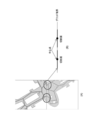
- FIG. 5 is a flowchart showing a centerline generation processing routine of the centerline generation device in the embodiment of the present invention. It is a figure for demonstrating the method of generating a center line using the characteristic of Delaunay triangulation. It is a figure for demonstrating the method of generating a center line using the characteristic of a Voronoi diagram.
- the Delaunay triangulation method is used to perform triangulation, and if there is a non-shaped triangle, recalculate. Then, as shown in FIG. 24B, a node is generated at the center of gravity of the triangle.
- points are generated at even intervals with respect to the frame line of the shape.
- a Voronoi polygon is generated for the generated points.
- the center line is the side of each Voronoi polygon that does not intersect the frame line of the original shape. Further, as shown in FIG. 25D, overlapping line segments are removed or vertices are thinned to simplify the center line.
- both the method using the characteristics of the Delaunay triangulation and the method using the characteristics of the Voronoi diagram include many nodes and links that are useless as a network for route search etc. I'm out. Therefore, after the centerline is generated, the minimum necessary correction to use as network data for route search (decimation of nodes in the method using the characteristics of Delaunay triangulation, overlapping line in the method using the characteristics of Voronoi diagram) The removal and node thinning) processing also takes time.
- the centerline generation device As compared with the conventional method, it does not largely depend on the shape of the indoor space of the input data, recalculation is unnecessary, the generation cost is suppressed, and the network is reduced. Allows you to generate data.
- the shape of the passage in the indoor space is input, and the characteristics of the shape are used to generate the center line that is the source of the network data.
- the generated center line is a continuous line that does not intersect with the frame line of the shape of the passage in the input indoor space and can be connected by a straight line from any internal position of the shape. Also, by generating a center line by paying attention to the concave vertex of the input indoor space shape, the generated center line does not intersect with the frame line of the shape of the input indoor space passage, and the shape is arbitrary. Meet that it is an unbroken line that can be connected by a straight line from the position inside.
- the input indoor space shape has a large area or a large number of vertices, divide it into grids, generate center lines for each grid, connect the center lines of each grid, and then connect one center line. By generating, the generation cost is suppressed.
- FIG. 1 is a block diagram showing the configuration of a network data generation system 100 according to the embodiment of the present invention.
- 2D architectural CAD computer-aided design
- digital vector data such as a 3D model included in BIM (Building Information Modeling) data are used to generate the centerline.
- architectural CAD is software that creates drawings such as a plan view, an elevation view, a cross-sectional view, or a perspective view of a three-dimensional structure such as a building or a structure.
- the CAD for architecture has a layer definition, and in general, in addition to walls and corridors, pillars, shops, toilets, escalators, etc. can be divided into layers and managed.
- BIM manages a digital model including a three-dimensional building shape and attribute information.
- BIM has a class definition, and IFC (Industry Foundation Classes), which is one format of BIM data, is defined for each structure such as hierarchy, space, stairs, doors, and pillars.
- IFC Industry Foundation Classes
- the input data shall be managed such that the shapes of rooms, corridors, entrances, stairs, elevators, etc. are pre-specified by layer and class definitions.
- a network data generation system 100 includes an indoor spatial data storage device 10 that stores this input data, a centerline generation device 20 that generates a centerline from the input data, and a centerline that stores the result. It includes a data storage device 30, a network data generation device 40 that automatically generates network data from the generated center line, and a network data storage device 50 that stores the generated network data.
- the center line generation device 20 can be configured by a computer including a CPU, a RAM, and a ROM that stores programs and various data for executing each processing routine described later.
- the centerline generation device 20 is functionally provided with an input unit 22, a calculation unit 24, and an output unit 26, as shown in FIG.
- the input unit 22 receives input data representing a passage, which is a movable area in the indoor space represented by the two-dimensional vector data, from the indoor space data storage device 10.
- a passage is a space for moving between rooms.
- the number of entrances / exits connected to the space is two or more and the shape of the space is a concave gyrus (perforated) polygon, it corresponds to a passage.
- the calculation unit 24 includes a grid division unit 240, a centerline generation unit 242, and a centerline connection unit 244.
- the grid division unit 240 divides the indoor space represented by the two-dimensional vector data in the input data into a grid of a predetermined size. Details of the processing of the grid division unit 240 will be described later.
- the center line generation unit 242 uses at least concave vertices that are elements that form two-dimensional vector data for each grid, does not intersect the frame line of the passage in the indoor space, and is formed by a plurality of straight lines. To generate a centerline.
- the center line connection unit 244 connects the center lines generated for each grid. Details of the processing of the center line connection unit 244 will be described later.
- the centerline generation unit 242 generates a centerline necessary for generating network data of indoor space.
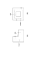
- a centerline is needed to generate network data. For example, description will be made using the shapes shown in FIGS.
- the shape shown in FIG. 3 (A) has no concave angle, for example, even if there are a plurality of entrances / exits at any position of the outer frame, the entrances / exits can be connected by a straight line, and therefore the center line is It is unnecessary.
- the centerline generation device 20 when the shape of the passage of the indoor space data that is the input data of the centerline generation device 20 has a reentrant angle and when it has an inner frame, the centerline is generated so that the line connected between the entrances has a shape. Prevents it from going outside, crossing the outer frame of the shape, and connecting lines crossing the inner frame of the shape.
- the entrance / exit passes through the centerline of the shape, so that it does not go out of the outer frame, does not intersect with the outer frame, and does not intersect with the inner frame. It will be possible to derive.
- Non-Patent Document 1 As an algorithm for generating a center line for a shape, conventionally, there is a method using a characteristic of Delaunay triangulation (Non-Patent Document 1) and an algorithm using a characteristic of a Voronoi diagram (Non-Patent Document 2).
- both methods are algorithms that largely depend on the size of the shape area and the complexity of the shape (number of vertices), as described above, and the generation cost is difficult to apply to actual data.
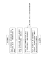
- the centerline generation unit 242 generates the centerline using generation logic that does not largely depend on the complexity of the shape when generating the centerline. This generation logic is shown in FIG. 5, and the transition of the center line generation of each step of the generation logic is shown in FIGS.
- Step 1 using the reentrant vertices, create the points where the first straight line and the second straight line forming the center line intersect. Specifically, a bisector of a corner is drawn from each of the reentrant vertices, and the center point of the bisector of the reentrant apex and the point at which the bisector of each reentrant apex intersects the centerline. It is created as a point where the first straight line and the second straight line constituting
- a concave corner vertex (circle mark in FIG. 7) of the shape is extracted from the shape of the passage in the indoor space for which the center line is generated as shown in FIG.
- a line (thick line in FIG. 7) drawn until the line intersects the shape frame line is extracted (Step 1-1).
- Step 2 connect the points created in Step 1 above with a line.
- the line is not connected when it intersects with the frame line of the shape of the passage or when it intersects with another line.
- Step 2-2 the points (circles in Fig. 9) extracted in Step 1-2 are connected in a brute force manner (thick line in Fig. 9, Step 2-1). At that time, the connection is not made when it intersects with the frame line of the shape of the passage and when it intersects with the already connected line (thick line in FIG. 9). As a result, as shown in FIG. 10, the connection line (thick line in FIG. 10) connected in Step 2-1 is obtained (Step 2-2).
- Step 3 from the closed polygon surrounded by the connection lines obtained in Step 2 above, delete the connection line corresponding to the longest side until the closed polygon disappears.
- connection line (broken line in FIG. 11) is extracted (Step 3-1).
- Step 3-2 the longest connection line (broken line in FIG. 11) extracted in Step 3-1 is removed (Step 3-2).
- Step 4 there is a center point of the farthest frame line that can be connected from each vertex of the connection line obtained in Step 3 above without colliding with the frame line of the passage shape and without intersecting with other connection lines. When doing so, the vertex and the center point are connected. At this time, if there is another connecting line closer than the distance between the center point and the vertex, the vertex is not connected to the center point.
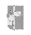
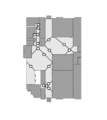
- Step 3-2 the vertices of the connecting lines (thick lines in FIG. 13) remaining in Step 3-2 are extracted, and the vertices and the center points (sides) of each side of the shape frame line (outer frame) 13 (black circle)) (Step 4-1). At that time, the connection is not made when it intersects with the frame line of the shape of the passage or when it intersects with the already connected connection line (thick line in FIG. 13).
- Step 3-2 For each vertex of the connecting line remaining in Step 3-2, only the longest connecting line among the connecting lines with the center point of the side is extracted as a candidate line (broken line in FIG. 13). However, if the shortest distance between the center point of the side that is the apex of the candidate line (broken line) and the connecting line (thick line) that is already connected is shorter than the length of the candidate line (broken line), the candidate line Is removed, otherwise the candidate line is left.
- connection line extracted in Step 3-2 (thick line in FIG. 14) and the candidate line remaining in Step 4-1 (broken line in FIG. 14) are obtained (Step 4-2).
- This is the center line generated by the generation logic of this embodiment for the shape of the passage in the indoor space for which the center line is generated.
- Step 4 "from each vertex of the connecting line, if there is a central point of the farthest frame line that can be connected without colliding with the frame line of the shape of the passage and without intersecting with other connecting lines, "Connecting the apex and the center point" needs to be searched by brute force between the apex of the generated center line and each side of the outer frame of the frame line of the shape of the passage.
- the cost may increase depending on the number of generated center lines and the number of sides of the shape frame line.
- the centerline generation logic has the possibility of generating the generation cost depending on the original shape, although there is a consideration to suppress the generation cost by focusing on the concave corner vertices.
- the grid division unit 240 sets the grid division unit 240 in FIG. As shown in FIG. 7, the shape of the passage in the indoor space is divided into small units by a grid, and the centerline generation unit 242 applies the above-described centerline generation logic to each of the small unit grids to generate a centerline.
- the center line connection unit 244 connects the center lines between the grids. As a result, as shown in FIG. 18A, since the center line is generated for each grid, the number of vertices and center points is reduced, and the generation cost is reduced.
- the center line connection unit 244 connects the center lines generated for each grid. Specifically, the center point of the grid cut surface (see FIG. 18B) and the closest vertex of the already generated center line are connected to both sides of the grid cut surface. With this, it is possible to always generate a centerline having the center point of the grid cutting plane as an apex so that the centerlines between the grids are always connected, and it is possible to generate one centerline without breaks.
- FIG. 19A when the center point of the cut surface between the grids and the vertex of the closest center line are connected to each other and the outer frame intersects, As shown in B), the outer frame is cut along a line E connecting the center point of the cut surface and the apex of the center line, and the closed polygonal shape formed by the line E and the outer frame is cut. In order to increase the size, a shape surrounded by a line F separated by a predetermined distance from each side of the polygon is generated. Then, as shown in FIG. 19C, of the sides of the generated shape, the sides G, H, and I that are not parallel to the cut line E are adopted to generate a center line that bypasses the outer frame. To do.
- FIG. 20 (A) when connecting the center point of the cutting plane between the grids and the vertex of the closest center line and intersecting the inner frame, FIG. As shown, of the two closed polygonal shapes formed by the line J and the inner frame by cutting the inner frame with a line J connecting the center point of the cut surface and the apex of the center line A shape surrounded by a line K separated by a predetermined distance from each side of the polygon is generated such that the polygon having the smaller area is made larger. Then, as shown in FIG. 20C, of the sides of the generated shape, the sides L, M, and N that are not parallel to the cut line J are adopted to generate a center line that bypasses the inner frame. To do.
- the centerline generation cost from a polygon having about 10,000 vertices is, for example, 18 hours when grid division is not performed, by the method of dividing into grids as described above. It was confirmed that the calculation time could be reduced to about 2 minutes and 30 seconds without cutting the center line when the grid was divided into 10 ⁇ 10 by the method of the present embodiment and divided into 100 grids. Further, comparing the center line when the center line is generated without dividing the grid (see FIG. 21) with the center line when the center lines are connected after the grid division (see FIG. 22), the shape is large. It was confirmed that it was not different.
- each of the target spaces which is a part of the indoor space, is divided into the room, the passage, the entrance, and the connection of the floor from the input data, and the generated data is generated.
- the indoor space consists of links that represent passages and nodes that are the start or end points of the links. Automatically generate network data.
- the target space can be distributed by the class and layer definition of the input data, the name and attribute information attached to the shape, it will be distributed to rooms, passages, entrances, and floor connections for each hierarchy.
- the room is a space that can be the destination of the navigation point.
- a room corresponds to a room when the number of entrances and exits connected to the space is one. If the shape of the space is a convex polygon, it corresponds to a room.
- the space is an area that divides the indoor space into meaningful units (passages, rooms).
- the space is a movable area where network data is generated.
- the doorway is the place that connects the spaces (no doors and walls), and the floor connection is the place that connects the floors of the indoor space (stairs, elevators, escalators, etc.).
- the link is a line drawn in the movable area on the assumption that a moving body (person, wheelchair, stroller, robot, drone, etc.) can move on the link.
- Both ends of the link are always nodes, and in addition to basic attribute information such as direction and length, the link can have characteristics of the movable area such as height, width, step, number of steps, and handrails as attribute information. . If there is a branch in the middle of the link or if the direction of the link is changed, the node is hit at the starting point and the link is divided.
- a node is the starting point or the ending point of a link. In addition to changing the direction of the link (creating a curve), branching the link, etc., a node will be generated, and if you want to set a navigation point near the entrance / exit, intentionally add it in the middle of the link. Sometimes you hit a node to split a link.
- the attribute information included in the input data includes information directly included as attribute information in “room”, “passage”, “entrance / exit”, and “floor connection”, and shapes that are not included directly.
- the shape for example, the handrail on the stairs, the number of toilet bowls in the toilet
- the attribute information of the shape for example, the material of the floor surface in the space
- POI is an abbreviation for Point of Interest, and manages representative points for the shape of a space (store, room, toilet, etc.) and its attributes.
- input data representing a passage which is a movable area in the indoor space represented by two-dimensional vector data
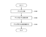
- the center line generation device 20 executes the center line generation processing routine shown in FIG.
- step S100 the indoor space represented by the two-dimensional vector data is divided into grids of a predetermined size based on the input data.
- step S102 the center line of the passage in the grid is generated for each grid according to the generation logic shown in FIG.
- step S104 the center lines generated for each grid are connected to generate one continuous center line, and the output unit 26 stores the center line in the center line data storage device 30 to execute the center line generation processing routine. finish.
- the centerline generation device in the indoor space, at least the concave corner vertices that are the elements forming the two-dimensional vector data expressing the passage of the indoor space are used.
- generating a continuous center line that does not intersect the passage line and is composed of multiple straight lines it is possible to reduce the amount of calculation and generate a center line for generating network data for indoor space. it can.
- the network data generation system by suppressing the calculation amount in the generation of the center line, it is possible to suppress the calculation amount and generate the network data of the indoor space.
- the center line may be generated without dividing the grid.
- the centerline generation device 20 described above has a computer system inside, the “computer system” also includes a homepage providing environment (or display environment) if a WWW system is used. Let's assume.
- the program can be stored in a computer-readable recording medium and provided, or provided via a network. It is also possible to do so.
Landscapes
- Engineering & Computer Science (AREA)
- Physics & Mathematics (AREA)
- Theoretical Computer Science (AREA)
- General Physics & Mathematics (AREA)
- Geometry (AREA)
- Computer Hardware Design (AREA)
- Pure & Applied Mathematics (AREA)
- General Engineering & Computer Science (AREA)
- Evolutionary Computation (AREA)
- Computational Mathematics (AREA)
- Mathematical Analysis (AREA)
- Mathematical Optimization (AREA)
- Civil Engineering (AREA)
- Structural Engineering (AREA)
- Architecture (AREA)
- Mathematical Physics (AREA)
- Business, Economics & Management (AREA)
- Educational Administration (AREA)
- Educational Technology (AREA)
- Computer Networks & Wireless Communication (AREA)
- Processing Or Creating Images (AREA)
- Image Generation (AREA)
- Instructional Devices (AREA)
Abstract
計算量を抑えて、屋内空間のネットワークデータを生成するための中心線を生成することができる。 中心線生成部は、凹角頂点を用いて、中心線を構成する第1の直線と第2の直線が交わる点を作成する(Step1)。上記Step1で作成した点間を線で接続する(Step2)。上記Step2で得られた接続線で囲われた閉多角形から、最も長い辺に対応する接続線を削除することを、閉多角形がなくなるまで繰り返す(Step3)。上記Step3で得られた接続線の各頂点から、通路の形状の枠線にぶつからず、かつ、他の接続線と交差せずに接続できる、一番遠い枠線の中心点が存在する場合に、当該頂点と中心点とを接続する(Step4)。
Description
本発明は、屋内空間のネットワークデータを生成するための中心線を生成する中心線生成装置、ネットワークデータ生成システム、及びプログラムに関する。
従来より、ネットワークデータの元となる中心線を生成する従来技術として、ドロネ三角形分割の特性を利用する方法(非特許文献1)やボロノイ図の特性を利用する方法(非特許文献2)が知られている。
Filippo Mortari,"Automatic Extraction of Improved Geometrical Network Model from CityGML for Indoor navigation",<インターネット検索:https://3d.bk.tudelft.nl/pdfs/FilippoMortari_thesis.pdf 検索日:2018/10/05>
奥秋 恵子,"道路形状ポリゴンを用いた、道路幅員ネットワークデータの自動生成",<インターネット検索:https://www.gisa-japan.org/conferences/proceedings/2012/papers/D-1-4.pdf 検索日:2018/10/05>
上記非特許文献1、2に記載のどちらの手法でも、生成した中心線に不要な部分が存在するため、それらの補正処理に時間がかかってしまうという課題がある。
本発明は、上記の事情を鑑みてなされたものであり、計算量を抑えて、屋内空間のネットワークデータを生成するための中心線を生成することができる中心線生成装置、ネットワークデータ生成システム、及びプログラムを提供することを目的とする。
上記目的を達成するために、本発明に係る中心線生成装置は、2次元ベクトルデータで表現された屋内空間における移動可能領域である通路の中心線を生成する中心線生成装置であって、少なくとも、前記2次元ベクトルデータを構成する要素である凹角頂点を用いて、前記屋内空間における通路の枠線と交差せず、かつ複数の直線で構成された連続する中心線を生成する中心線生成部を含んで構成されている。
また、本発明に係るネットワークデータ生成システムは、上記の中心線生成装置と、前記簡素化された前記中心線に基づいて、前記通路を表すリンクおよび前記リンクの起点若しくは終点となるノードからなるネットワークデータを生成するネットワークデータ生成装置と、を含んで構成されている。
また、本発明のプログラムは、コンピュータを、上記の中心線生成装置を構成する各部として機能させるためのプログラムである。
以上説明したように、本発明の中心線生成装置、ネットワークデータ生成システム、及びプログラムによれば、計算量を抑えて、屋内空間のネットワークデータを生成するための中心線を生成することができる、という効果が得られる。
以下、図面を参照して本発明の実施の形態を詳細に説明する。
<概要>
まず、ドロネ三角形分割の特性を利用して中心線を生成する方法について説明する。ドロネ三角形分割の特性を利用した方法では、元形状をドロネ三角形分割し、その重心同士をつなぐことで中心線を生成する。
まず、ドロネ三角形分割の特性を利用して中心線を生成する方法について説明する。ドロネ三角形分割の特性を利用した方法では、元形状をドロネ三角形分割し、その重心同士をつなぐことで中心線を生成する。
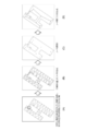
具体的には、図24(A)に示すように、ドロネ三角形分割法を用いて三角形分割し、形状外の三角形が存在していたら再計算する。そして、図24(B)に示すように、三角形の重心にノードを生成する。
そして図24(C)に示すように、ノードを間引く。このとき、つないだ結果、直線に近いノードを除去する。そして、図24(D)に示すように、ノード間にリンクを生成する。このように、ドロネ三角形分割の特性を利用して中心線を生成する方法では、生成アルゴリズムの特性上、元形状の複雑さによって、ネットワークデータの生成コストが高くなる傾向にある。さらに、元形状によっては、再計算が繰り返され、時間がかかることが実証の結果明らかとなった。
次に、ボロノイ図の特性を利用して中心線を生成する方法について説明する。ボロノイ図の特性を利用した方法では、元形状の辺上に、一定間隔の点をうち、その点群からボロノイ多角形を生成する。このとき、隣り合う多角形同士を融合し、融合した多角形の辺のうち元形状の内部にある辺を中心線とする。
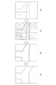
具体的には、図25(A)に示すように、形状の枠線に対して、等間隔に点を生成する。そして、図25(B)に示すように、生成した点に対して、ボロノイ多角形を生成する。
そして、図25(C)に示すように、各ボロノイ多角形の辺のうち元形状の枠線と交差しない辺を中心線とする。また、図25(D)に示すように、重複する線分の除去や頂点の間引きを行い、中心線を簡素化する。
このように、ボロノイ図の特性を利用して生成した中心線は、生成アルゴリズムの特性上、元形状の複雑さによって、ネットワークデータの生成コストが高くなる傾向にある。
上述したように、ドロネ三角形分割の特性を利用した手法も、ボロノイ図の特性を利用した手法も、生成した結果そのままでは、経路探索などのネットワークとして利用するには無駄なノードやリンクを多く含んでいる。従って、中心線を生成した後に、経路探索のネットワークデータとするための必要最低限の補正(ドロネ三角形分割の特性を利用した手法におけるノードの間引き、ボロノイ図の特性を利用した手法における重複線の除去やノードの間引き)処理も時間を要することになる。
そこで、本発明の実施の形態に係る中心線生成装置では、従来の手法と比較して、入力データの屋内空間の形状に大きく依存せず、再計算を不要とし、生成コストを抑えて、ネットワークデータを生成できるようにする。
具体的には、屋内空間のネットワークデータを生成するために、屋内空間の通路の形状を入力として、その形状の特徴を利用して、ネットワークデータの元となる中心線を生成する。
ここで、生成される中心線は、入力する屋内空間の通路の形状の枠線と交差せず、かつ、その形状の任意の内部の位置から直線でつなげることができる途切れのない線となる。また、入力する屋内空間形状の凹角頂点に着目し中心線を生成することで、生成される中心線は、入力する屋内空間の通路の形状の枠線と交差せず、かつ、その形状の任意の内部の位置から直線でつなげることができる途切れのない線であることを満たす。
また、入力する屋内空間形状の面積が大きい場合や頂点数が多い場合は、グリッドに分割し、グリッド毎に中心線を生成したうえで、各グリッドの中心線を接続し、一つの中心線を生成することで、生成コストを抑える。
また、各グリッド間の中心線を接続する際に、通路の枠線と交差してしまう場合は、迂回する中心線を生成することで、入力する屋内空間の形状の枠線と交差せず、かつ、その形状の任意の内部の位置から直線でつなげることができる途切れのない線であることを満たす。
<本発明の実施の形態に係るネットワークデータ生成システムの構成>
図1は、本発明の実施の形態に係るネットワークデータ生成システム100の構成を示すブロック図である。
図1は、本発明の実施の形態に係るネットワークデータ生成システム100の構成を示すブロック図である。
一般的に、中心線の生成のために、建築設計時に作成する2Dの建築用CAD(computer-aided design)データや、BIM(Building Information Modeling)データに含まれる3Dモデルといったデジタルベクトルデータを利用する。
ここで、建築用CADは、建物や構造物などの建築物の立体を平面図・立面図・断面図、あるいは透視図等の図面を作成するソフトウェアである。建築用CADでは、レイヤ定義を有し、一般的に、壁や廊下のほか、柱、店舗、トイレ、エスカレータなどをレイヤで分けて管理することができる。
また、BIMは、3次元の建物形状および属性情報が含まれるデジタルモデルを管理するものである。BIMでは、クラス定義を有し、BIMデータの一つのフォーマットであるIFC(Industry Foundation Classes)では、階層、空間、階段、ドア、柱などの構造物毎に定義付けられている。
BIMデータを利用する際は、階層毎に水平投射することで、2Dのベクトルデータとして扱う。
また、入力データは、部屋や通路や、出入口、階段、エレベータなどの形状があらかじめレイヤやクラス定義などで意味付けられて管理されているものとする。
本発明の実施形態に係るネットワークデータ生成システム100は、この入力データを記憶する屋内空間データ記憶装置10と、入力データから中心線を生成する中心線生成装置20と、その結果を格納する中心線データ記憶装置30と、生成された中心線からネットワークデータを自動生成するネットワークデータ生成装置40と、生成したネットワークデータを記憶するネットワークデータ記憶装置50とを含む。
<中心線生成装置の構成>
次に、中心線生成装置20の構成について説明する。図2に示すように、中心線生成装置20は、CPUと、RAMと、後述する各処理ルーチンを実行するためのプログラムや各種データを記憶したROMと、を含むコンピュータで構成することが出来る。この中心線生成装置20は、機能的には図2に示すように、入力部22と、演算部24と、出力部26を備えている。
次に、中心線生成装置20の構成について説明する。図2に示すように、中心線生成装置20は、CPUと、RAMと、後述する各処理ルーチンを実行するためのプログラムや各種データを記憶したROMと、を含むコンピュータで構成することが出来る。この中心線生成装置20は、機能的には図2に示すように、入力部22と、演算部24と、出力部26を備えている。
入力部22は、屋内空間データ記憶装置10から、2次元ベクトルデータで表現された屋内空間における移動可能領域である通路を表す入力データを受け付ける。
ここで、通路とは、部屋と部屋を移動するための空間である。空間に接続している出入口数が2つ以上、かつ、空間の形状が凹回(穴あき)多角形の場合、通路に該当する。
演算部24は、図2に示すように、グリッド分割部240、中心線生成部242、及び中心線接続部244を備えている。
グリッド分割部240は、入力データにおける2次元ベクトルデータで表現された屋内空間を所定の大きさのグリッドに分割する。グリッド分割部240の処理の詳細については後述する。
中心線生成部242は、グリッドごとに、少なくとも、2次元ベクトルデータを構成する要素である凹角頂点を用いて、屋内空間における通路の枠線と交差せず、かつ複数の直線で構成された連続する中心線を生成する。
中心線接続部244は、グリッドごとに生成された中心線を接続する。中心線接続部244の処理の詳細については後述する。
<中心線生成部242による処理の詳細>
中心線生成部242では、屋内空間のネットワークデータを生成するために必要となる中心線を生成する。まず、ネットワークデータを生成するために、なぜ、中心線が必要となるのかを示す。例えば、図3(A)~(C)で示す形状を用いて説明する。
中心線生成部242では、屋内空間のネットワークデータを生成するために必要となる中心線を生成する。まず、ネットワークデータを生成するために、なぜ、中心線が必要となるのかを示す。例えば、図3(A)~(C)で示す形状を用いて説明する。
図3(A)で示す形状は、凹角が存在しないため、例えば、外枠の任意の位置に出入口が複数存在していても、その出入口間は直線で接続することができるため、中心線は不要である。
しかし、図3(B)で示す形状は凹角が存在するため、出入口の位置によってはその出入口間を直線で接続することができない場合がある。すわなち、接続した線が形状の外側に出てしまったり、形状の外枠と交差する場合、ネットワークデータとして誤りとなってしまう。
また、図3(C)で示す形状は内枠が存在するため、出入口の位置によってはその出入口間を直線で接続することができない場合がある。すわなち、接続した線が形状の内枠と交差する場合、ネットワークデータとして誤りとなってしまう。
従って、中心線生成装置20の入力データとなる屋内空間データの通路の形状が凹角を持つ場合と、内枠を持つ場合は、中心線を生成することで、出入口間で接続した線が形状の外側に出てしまったり、形状の外枠と交差したり、接続した線が形状の内枠と交差することを防ぐ。
図4(A)、(B)で示す通り、出入口は形状に対する中心線を経由することで、外枠の外に出ず、外枠と交差せず、内枠と交差しない通路のネットワークデータを導出することができるようになる。
ここで、形状に対する中心線を生成するアルゴリズムには、従来、ドロネ三角形分割の特性を利用する方法(非特許文献1)や、ボロノイ図の特性などを利用するアルゴリズム(非特許文献2)が存在するが、どちらの方式も、上述した通り、形状の面積の大きさや、形状の複雑さ(頂点数)に大きく依存するアルゴリズムであり、実データに対して適用するには生成コスト的に厳しいことが、実証の結果、明らかとなった。
従って、中心線生成部242は、この中心線を生成する際の形状の複雑さに大きく依存しない生成ロジックを用いて中心線を生成する。この生成ロジックを図5に示し、生成ロジックの各Stepの中心線生成の遷移を図6~14に示す。
Step1では、凹角頂点を用いて、中心線を構成する第1の直線と第2の直線が交わる点を作成する。具体的には、凹角頂点の各々から角の2等分線を引き、凹角頂点の角の二等分線の中心点、及び、凹角頂点の各々の二等分線が交わる点を、中心線を構成する第1の直線と第2の直線が交わる点として作成する。
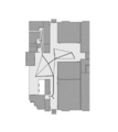
例えば、図6に示す中心線生成対象となる屋内空間の通路の形状から、図7に示すように、形状の凹角頂点(図7の丸印)を抽出し、凹角頂点の角の二等分線を、形状の枠線と交差するまで引いた線(図7の太線)を抽出する(Step1-1)。
そして、図8に示すように、Step1-1で抽出した線(図8の太線)の中点と、二等分線同士の交点とを抽出する(図8の丸印、Step1-2)。
Step2では、上記Step1で作成した点間を線で接続する。このとき、通路の形状の枠線と交差する場合や、他の線と交差する場合には、線で接続しない。
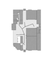
例えば、図9に示すように、Step1-2で抽出した点(図9の丸印)を総当たりで接続している(図9の太線、Step2-1)。その際、通路の形状の枠線と交差する場合、及び既に接続している線(図9の太線)と交差する場合は接続しない。これにより、図10に示すように、Step2-1で接続した接続線(図10の太線)が得られる(Step2-2)。
Step3では、上記Step2で得られた接続線で囲われた閉多角形から、最も長い辺に対応する接続線を削除することを、閉多角形がなくなるまで繰り返す。
例えば、図11に示すように、Step2-2で得られた接続線(図11の太線)のうち、閉多角形となっている接続線の組合せを抽出し、その組み合わせの内、一番長い接続線(図11の破線)を抽出する(Step3-1)。
そして、図12に示すように、Step3-1で抽出した一番長い接続線(図11の破線)を除去する(Step3-2)。
Step4では、上記Step3で得られた接続線の各頂点から、通路の形状の枠線にぶつからず、かつ、他の接続線と交差せずに接続できる、一番遠い枠線の中心点が存在する場合に、当該頂点と中心点とを接続する。このとき、中心点と頂点との距離より近い他の接続線が存在した場合は、当該頂点と中心点とを接続しない。
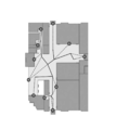
例えば、図13に示すように、Step3-2で残った接続線(図13の太線)の頂点を抽出し、その各頂点と、形状の枠線(外枠)の各辺の中心点(図13の黒丸)とを接続する(Step4-1)。その際、通路の形状の枠線と交差する場合や、既に接続している接続線(図13の太線)と交差する場合は接続しない。
また、Step3-2で残った接続線の頂点毎に、辺の中心点との接続線のうち、一番長い接続線のみを候補線として抽出する(図13の破線)。ただし、その候補線(破線)の頂点である辺の中心点と、既に接続している接続線(太線)との最短距離が、当該候補線(破線)の長さより短い場合は、当該候補線を除去し、そうでない場合は当該候補線を残す。
そして、図14に示すように、Step3-2にて抽出した接続線(図14の太線)とStep4-1で残った候補線(図14の破線)が得られる(Step4-2)。これが、中心線生成対象の屋内空間の通路の形状に対して本実施の形態の生成ロジックで生成した中心線となる。
なお、通路の形状に凹角頂点が1つしか存在しない場合、接続線が生成されない。その場合は、図15に示すように、凹角頂点の二等分線の中心点(図15の白丸)から、凹角頂点(図15の黒丸)をなす2つの枠線の辺A,Bと平行な線C,Dを生成して、中心線とすれば良い。
<グリッド分割部240及び中心線接続部244の処理の詳細>
本実施の形態の生成ロジックの場合、通路の形状の特徴となる凹角頂点のみに着目するため、従来の手法と比べ、大幅に生成コストを削減することができる。
本実施の形態の生成ロジックの場合、通路の形状の特徴となる凹角頂点のみに着目するため、従来の手法と比べ、大幅に生成コストを削減することができる。
この手法により、1万点ほどの頂点を持った多角形からの中心線生成コストについて、従来の方式では数日たっても中心線を生成できなかったのに対し、上記の生成ロジックを用いると18時間で中心線が生成できることが明らかとなった。
しかし、上記のStep3における「接続線で囲われた閉多角形から、最も長い辺に対応する接続線を削除する」ことは、生成した接続線の総当たりで閉多角形を探索する必要がある。
また、Step4における「接続線の各頂点から、通路の形状の枠線にぶつからず、かつ、他の接続線と交差せずに接続できる、一番遠い枠線の中心点が存在する場合に、当該頂点と中心点とを接続する」は、生成した中心線の頂点と、通路の形状の枠線のうち外枠の各辺との総当たりで探索する必要がある。
従って、生成済みの中心線の数や、形状の枠線の辺の数に依存して、コストが大きくなる恐れがある。
そこで、本実施の形態では、中心線の生成ロジックを用いた中心線の生成コストの改善手法を用いる。
上記で述べた通り、中心線の生成ロジックは、凹角頂点に着目することで生成コストを抑える考慮はあるものの、元形状によっては、生成コストを要する可能性を含んでいる。
従って、生成コストを要する場合(例えば、図16に示すように元形状の頂点数が多い場合や面積が大きい場合など)であっても生成コストを抑えるために、グリッド分割部240は、図17に示すように、屋内空間の通路の形状をグリッドで小さい単位に分割し、中心線生成部242は、その小さい単位のグリッド毎に、上記の中心線生成ロジックを適用して中心線を生成し、中心線接続部244は、各グリッド間の中心線同士を接続する。これにより、図18(A)に示すように、グリッド毎に中心線を生成するため、頂点と中心点が減り、生成コストが下がる。
中心線接続部244は、グリッドごとに生成された中心線を接続する。具体的には、グリッド切断面の両側それぞれに対し、グリッド切断面の中心点(図18(B)参照)と、既に生成されている中心線の一番近い頂点とを接続する。これにより、グリッド間の中心線が必ずつながるように、グリッド切断面の中心点を頂点とする中心線を必ず生成することができ、切れ目のない一つの中心線を生成することができる。
ここで、グリッド間の切断面の中心点と中心線を接続する際に、通路の形状の枠線と交差してしまっては、中心線の意味を失ってしまう。従って、そのような場合は、迂回する中心線を生成することで、接続した中心線が形状の枠線と交差することを防ぐ。
具体的には、図19(A)に示すように、グリッド間の切断面の中心点と、一番近い中心線の頂点と接続したときに、外枠と交差する場合には、図19(B)に示すように、外枠を、切断面の中心点と中心線の頂点とをつないだ線Eで切り、当該線Eと外枠とで形成された、閉じた多角形の形状に対して、大きくするように、多角形の各辺に対して所定距離離れた線Fで囲んだ形状を生成する。そして、図19(C)に示すように、生成した形状の辺のうち、切った当該線Eと平行な線でない辺G、H、Iを採用して、外枠を迂回する中心線を生成する。
また、図20(A)に示すように、グリッド間の切断面の中心点と、一番近い中心線の頂点と接続したときに、内枠と交差する場合には、図20(B)に示すように、内枠を、切断面の中心点と中心線の頂点とをつないだ線Jで切り、当該線Jと内枠とで形成された、2つの閉じた多角形の形状のうち、面積の小さいほうの多角形の形状に対して、大きくするように、多角形の各辺に対して所定距離離れた線Kで囲んだ形状を生成する。そして、図20(C)に示すように、生成した形状の辺のうち、切った当該線Jと平行な線でない辺L、M、Nを採用して、内枠を迂回する中心線を生成する。
また、グリッド内の中心線が存在しない(グリッド内の形状に凹角頂点が存在しない)場合は、グリッド内の通路の形状の重心と、グリッド間の切断面の中心点を接続すれば良い。
本実施の形態では、上述したようにグリッドに分割する手法により、1万点ほどの頂点を持った多角形からの中心線生成コストについて、例えば、グリッド分割しない場合は18時間かかっていたのが、本実施の形態の手法にて10×10に分割し、100個のグリッドに分割したところ、中心線が切れることなく、計算時間を2分30秒程度まで削減できることを確認した。更に、グリッド分割せずに中心線を生成した場合の中心線(図21参照)と、グリッド分割後に中心線同士を接続した場合の中心線(図22参照)とを比較しても大きく形状は異なっていないことが確認できた。
<ネットワークデータ生成装置40の構成>
本発明の実施の形態に係るネットワークデータ生成装置40では、入力データから、階層毎に、屋内空間の一部である対象空間の各々を、部屋、通路、出入口、階の接続に振り分けると共に、生成された中心線に基づいて、中心線の頂点、交点にノードを生成し、そのノード間をリンクで接続することで、通路を表すリンクおよびリンクの起点若しくは終点となるノードからなる、屋内空間のネットワークデータを自動生成する。
本発明の実施の形態に係るネットワークデータ生成装置40では、入力データから、階層毎に、屋内空間の一部である対象空間の各々を、部屋、通路、出入口、階の接続に振り分けると共に、生成された中心線に基づいて、中心線の頂点、交点にノードを生成し、そのノード間をリンクで接続することで、通路を表すリンクおよびリンクの起点若しくは終点となるノードからなる、屋内空間のネットワークデータを自動生成する。
具体的には、対象空間を、入力データが持つクラスやレイヤ定義、形状に付けられた名称や属性情報により振り分け可能な場合は、階層毎に部屋、通路、出入口、階の接続に振り分ける。
ここで、部屋は、ナビゲーションポイントの目的地となり得る空間である。空間に接続している出入口数が1つの場合、部屋に該当する。また、空間の形状が、凸多角形の場合、部屋に該当する。
また、空間は、屋内空間を意味のある単位(通路、部屋)に分割した領域である。また、空間は、ネットワークデータの生成対象となる移動可能な領域である。
また、出入口は、空間と空間とを接続する場所(ドア、壁無し)であり、階の接続は、屋内空間の階層間を接続する場所(階段、エレベータ、エスカレータ等)である。
また、リンクは、移動体(人、車いす、ベビーカー、ロボット、ドローン等)がリンク上を移動可能であることを想定し、移動可能な領域に引かれる線である。リンクの両端は必ずノードであり、リンクは、向き、長さという基本的な属性情報に加え、高さ、幅、段差、段数、手すり有といった移動可能領域の特徴を属性情報として持つことができる。また、リンクの途中で分岐がある場合や、リンクの向きを変える場合には、その起点となる点にノードを打ち、リンクを分割する。
ノードは、リンクの起点、もしくは終点となる点である。リンクの向きを変える(カーブを作成する)、リンクを分岐させる、などの場合にノードが生成されるほか、出入口の最寄にナビゲーションポイントを設けたい場合などには、意図的にリンクの途中にノードを打って、リンクを分割する場合がある。
また、ネットワークデータを生成する際に、入力データがもつ属性情報を付加することで、より、利用価値が高いデータを効率的に自動生成することができる。
ここで、入力データがもつ属性情報には、「部屋」、「通路」、「出入口」、「階の接続」に直接属性情報として含まれる情報や、直接的に含まれていないがそれらの形状の近傍や内部に含まれる形状(例えば、階段における手すりや、トイレにおける便器の数など)や、その形状がもつ属性情報(例えば、空間における床面の素材など)を自動的に抽出することで得られる情報も含まれる。
属性情報を付加する際、同一の属性情報を複数のネットワークデータに付加する場合は、別途、POIを生成して、そのIDを属性情報に付加することで、データ量を削減することもできる。ここで、POIはPoint of Interestの略であり、空間(店舗、部屋、トイレ等)が持つ形状に対する代表点と、その属性とを管理するものである。
<本発明の実施の形態に係る中心線生成装置の作用>
次に、本発明の実施の形態に係る中心線生成装置20の作用について説明する。
次に、本発明の実施の形態に係る中心線生成装置20の作用について説明する。
まず、2次元ベクトルデータで表現された屋内空間における移動可能領域である通路を表す入力データが、屋内空間データ記憶装置10に格納されている。そして、屋内空間データ記憶装置10に格納されている入力データを、入力部22によって受け付けると、中心線生成装置20は、図23に示す中心線生成処理ルーチンを実行する。
まず、ステップS100において、入力データに基づいて、2次元ベクトルデータで表現された屋内空間を所定の大きさのグリッドに分割する。
そして、ステップS102において、グリッド毎に、上記図5に示す生成ロジックに従って、当該グリッド内の通路の中心線を生成する。
ステップS104では、グリッドごとに生成された中心線を接続して、切れ目のない一つの中心線を生成し、出力部26により、中心線データ記憶装置30に格納して、中心線生成処理ルーチンを終了する。
以上説明したように、本発明の実施の形態に係る中心線生成装置によれば、少なくとも、屋内空間の通路を表現する2次元ベクトルデータを構成する要素である凹角頂点を用いて、屋内空間における通路の枠線と交差せず、かつ複数の直線で構成された連続する中心線を生成することにより、計算量を抑えて、屋内空間のネットワークデータを生成するための中心線を生成することができる。
また、本発明の実施の形態に係るネットワークデータ生成システムによれば、中心線の生成における計算量を抑えることにより、計算量を抑えて、屋内空間のネットワークデータを生成することができる。
なお、本発明は、上述した実施形態に限定されるものではなく、この発明の要旨を逸脱しない範囲内で様々な変形や応用が可能である。
例えば、入力する屋内空間形状の面積が小さい場合や頂点数が少ない場合には、グリッド分割せずに中心線を生成してもよい。
また、上述の中心線生成装置20は、内部にコンピュータシステムを有しているが、「コンピュータシステム」は、WWWシステムを利用している場合であれば、ホームページ提供環境(あるいは表示環境)も含むものとする。
また、本願明細書中において、プログラムが予めインストールされている実施形態として説明したが、当該プログラムを、コンピュータ読み取り可能な記録媒体に格納して提供することも可能であるし、ネットワークを介して提供することも可能である。
10 屋内空間データ記憶装置
20 中心線生成装置
22 入力部
24 演算部
26 出力部
30 中心線データ記憶装置
40 ネットワークデータ生成装置
50 ネットワークデータ記憶装置
100 ネットワークデータ生成システム
240 グリッド分割部
242 中心線生成部
244 中心線接続部
20 中心線生成装置
22 入力部
24 演算部
26 出力部
30 中心線データ記憶装置
40 ネットワークデータ生成装置
50 ネットワークデータ記憶装置
100 ネットワークデータ生成システム
240 グリッド分割部
242 中心線生成部
244 中心線接続部
Claims (8)
- 2次元ベクトルデータで表現された屋内空間における移動可能領域である通路の中心線を生成する中心線生成装置であって、
少なくとも、前記2次元ベクトルデータを構成する要素である凹角頂点を用いて、前記屋内空間における通路の枠線と交差せず、かつ複数の直線で構成された連続する中心線を生成する中心線生成部
を含むことを特徴とする中心線生成装置。 - 前記中心線生成部は、前記凹角頂点を用いて、前記中心線を構成する第1の直線と第2の直線が交わる点を取得し、前記取得した点を接続することで中心線を生成することを特徴とする請求項1記載の中心線生成装置。
- 前記中心線生成部は、前記凹角頂点の角の二等分線を用いて前記中心線を生成することを特徴とする請求項1又は2記載の中心線生成装置。
- 前記中心線生成部は、前記凹角頂点の角の二等分線の中心点、及び、前記凹角頂点の各々の前記二等分線が交わる点を抽出し、抽出した点を接続することで前記中心線を生成することを特徴とする請求項3記載の中心線生成装置。
- 前記中心線生成部は、更に、生成された前記中心線で囲われた閉多角形から、最も長い辺に対応する中心線を削除することを特徴とする請求項1~請求項4の何れか1項記載の中心線生成装置。
- 前記2次元ベクトルデータで表現された屋内空間を所定の大きさのグリッドに分割するグリッド分割部と、
中心線接続部と、
を更に含み、
前記中心線生成部は、前記グリッドごとに前記中心線を生成し、
前記中心線接続部は、前記グリッドごとに生成された前記中心線を接続する請求項1~請求項5の何れか1項記載の中心線生成装置。 - 請求項1~請求項6の何れか1項記載の中心線生成装置と、
前記生成された前記中心線に基づいて、前記通路を表すリンクおよび前記リンクの起点若しくは終点となるノードからなるネットワークデータを生成するネットワークデータ生成装置と、
を含むネットワークデータ生成システム。 - コンピュータを、請求項1~請求項6の何れか1項記載の中心線生成装置を構成する各部として機能させるためのプログラム。
Priority Applications (1)
| Application Number | Priority Date | Filing Date | Title |
|---|---|---|---|
| US17/287,842 US11625868B2 (en) | 2018-10-24 | 2019-10-18 | Center line generation device, network data generation system and program |
Applications Claiming Priority (2)
| Application Number | Priority Date | Filing Date | Title |
|---|---|---|---|
| JP2018200184A JP6996472B2 (ja) | 2018-10-24 | 2018-10-24 | 中心線生成装置、ネットワークデータ生成システム、及びプログラム |
| JP2018-200184 | 2018-10-24 |
Publications (1)
| Publication Number | Publication Date |
|---|---|
| WO2020085261A1 true WO2020085261A1 (ja) | 2020-04-30 |
Family
ID=70331417
Family Applications (1)
| Application Number | Title | Priority Date | Filing Date |
|---|---|---|---|
| PCT/JP2019/041209 Ceased WO2020085261A1 (ja) | 2018-10-24 | 2019-10-18 | 中心線生成装置、ネットワークデータ生成システム、及びプログラム |
Country Status (3)
| Country | Link |
|---|---|
| US (1) | US11625868B2 (ja) |
| JP (1) | JP6996472B2 (ja) |
| WO (1) | WO2020085261A1 (ja) |
Families Citing this family (1)
| Publication number | Priority date | Publication date | Assignee | Title |
|---|---|---|---|---|
| WO2025070595A1 (ja) * | 2023-09-28 | 2025-04-03 | 株式会社Muse | 地図生成装置、地図生成方法および地図生成システム |
Citations (4)
| Publication number | Priority date | Publication date | Assignee | Title |
|---|---|---|---|---|
| JP2003132353A (ja) * | 2001-10-29 | 2003-05-09 | Pasuko:Kk | 中心線生成プログラム |
| JP2011107770A (ja) * | 2009-11-12 | 2011-06-02 | Hitachi Ltd | 屋内空間データ作成支援システム及び屋内空間データ作成支援方法 |
| JP2013058173A (ja) * | 2011-09-09 | 2013-03-28 | Hitachi Information & Control Solutions Ltd | 2次元cadデータのためのオブジェクト抽出システム及びプログラム |
| JP2015210626A (ja) * | 2014-04-25 | 2015-11-24 | 株式会社日立ソリューションズ | 地図のネットワークデータ自動生成装置、ネットワークデータ自動生成方法及びネットワークデータ自動生成プログラム |
Family Cites Families (4)
| Publication number | Priority date | Publication date | Assignee | Title |
|---|---|---|---|---|
| US8699759B2 (en) * | 2009-10-12 | 2014-04-15 | Qualcomm Incorporated | Method and apparatus for automated determination of features on an electronic map |
| US11216599B2 (en) * | 2015-11-24 | 2022-01-04 | Takeshi SHIRABE | Method, apparatus and computer program for designing a corridor |
| US11409920B2 (en) * | 2016-11-14 | 2022-08-09 | Autodesk, Inc. | Generative design for architecture |
| US20220180595A1 (en) * | 2020-06-12 | 2022-06-09 | Boom Interactive, Inc. | System and method for creating three-dimensional renderings of environments from two-dimensional images |
-
2018
- 2018-10-24 JP JP2018200184A patent/JP6996472B2/ja active Active
-
2019
- 2019-10-18 WO PCT/JP2019/041209 patent/WO2020085261A1/ja not_active Ceased
- 2019-10-18 US US17/287,842 patent/US11625868B2/en active Active
Patent Citations (4)
| Publication number | Priority date | Publication date | Assignee | Title |
|---|---|---|---|---|
| JP2003132353A (ja) * | 2001-10-29 | 2003-05-09 | Pasuko:Kk | 中心線生成プログラム |
| JP2011107770A (ja) * | 2009-11-12 | 2011-06-02 | Hitachi Ltd | 屋内空間データ作成支援システム及び屋内空間データ作成支援方法 |
| JP2013058173A (ja) * | 2011-09-09 | 2013-03-28 | Hitachi Information & Control Solutions Ltd | 2次元cadデータのためのオブジェクト抽出システム及びプログラム |
| JP2015210626A (ja) * | 2014-04-25 | 2015-11-24 | 株式会社日立ソリューションズ | 地図のネットワークデータ自動生成装置、ネットワークデータ自動生成方法及びネットワークデータ自動生成プログラム |
Also Published As
| Publication number | Publication date |
|---|---|
| US11625868B2 (en) | 2023-04-11 |
| JP2020067827A (ja) | 2020-04-30 |
| JP6996472B2 (ja) | 2022-01-17 |
| US20210390743A1 (en) | 2021-12-16 |
Similar Documents
| Publication | Publication Date | Title |
|---|---|---|
| Teo et al. | BIM-oriented indoor network model for indoor and outdoor combined route planning | |
| Xu et al. | BIM-based indoor path planning considering obstacles | |
| CN109979006B (zh) | 室内路网模型构建方法及装置 | |
| Fu et al. | Generating straight skeleton-based navigation networks with Industry Foundation Classes for indoor way-finding | |
| JP7077913B2 (ja) | 中心線簡素化装置、ネットワークデータ生成システム、及びプログラム | |
| US11520944B2 (en) | System and method for modeling of parts with lattice structures | |
| Koltsova et al. | Visibility analysis for 3D urban environments | |
| CN107862738A (zh) | 一种基于移动激光测量点云进行室内结构化三维重建方法 | |
| Boguslawski et al. | BIM-GIS modelling in support of emergency response applications | |
| CN114777793A (zh) | 一种面向任意导航主体的bim地图提取及路径规划方法 | |
| NL2017238B1 (en) | A method and an apparatus for calculating a distance in an area | |
| JPWO2018016558A1 (ja) | シミュレーション装置、シミュレーションシステム、シミュレーション方法、及びプログラム | |
| KR101810663B1 (ko) | 비정형 슬라브 부재의 bim 데이터 변환장치 및 그 방법 | |
| CN116628828A (zh) | 一种大型建筑物拆除点确定方法、介质及系统 | |
| US11913804B2 (en) | Network data generator, network data generation method, and program | |
| JP6996472B2 (ja) | 中心線生成装置、ネットワークデータ生成システム、及びプログラム | |
| JP2003337836A (ja) | 解析用モデル作成方法および解析用モデル作成装置 | |
| CN113326545B (zh) | 面向典型梁桥结构健康检测的轻量语义bim建模系统及方法 | |
| Fu et al. | Automatic generation of path networks for evacuation using building information modeling | |
| CN113192181A (zh) | 面向综合体导航应用的室内多层次语义拓扑索引构建方法 | |
| JP6814261B2 (ja) | 経路結合装置、方法、及びプログラム | |
| JP7848279B2 (ja) | ナビゲーションマップ生成システム、ナビゲーションマップ生成方法及びナビゲーションマップ生成プログラム | |
| JP2020074060A (ja) | 経路情報生成装置、方法、及びプログラム | |
| CN113963089B (zh) | 一种基于a*算法的三维空间疏散模拟方法 | |
| Musliman et al. | Modeling dynamic weight for 3D navigation routing |
Legal Events
| Date | Code | Title | Description |
|---|---|---|---|
| 121 | Ep: the epo has been informed by wipo that ep was designated in this application |
Ref document number: 19877406 Country of ref document: EP Kind code of ref document: A1 |
|
| NENP | Non-entry into the national phase |
Ref country code: DE |
|
| 122 | Ep: pct application non-entry in european phase |
Ref document number: 19877406 Country of ref document: EP Kind code of ref document: A1 |