WO2020085050A1 - 推定方法、推定装置及び推定プログラム - Google Patents
推定方法、推定装置及び推定プログラム Download PDFInfo
- Publication number
- WO2020085050A1 WO2020085050A1 PCT/JP2019/039371 JP2019039371W WO2020085050A1 WO 2020085050 A1 WO2020085050 A1 WO 2020085050A1 JP 2019039371 W JP2019039371 W JP 2019039371W WO 2020085050 A1 WO2020085050 A1 WO 2020085050A1
- Authority
- WO
- WIPO (PCT)
- Prior art keywords
- failure
- network
- pattern information
- path
- network device
- Prior art date
- Legal status (The legal status is an assumption and is not a legal conclusion. Google has not performed a legal analysis and makes no representation as to the accuracy of the status listed.)
- Ceased
Links
Images




Classifications
-
- H—ELECTRICITY
- H04—ELECTRIC COMMUNICATION TECHNIQUE
- H04L—TRANSMISSION OF DIGITAL INFORMATION, e.g. TELEGRAPHIC COMMUNICATION
- H04L43/00—Arrangements for monitoring or testing data switching networks
- H04L43/10—Active monitoring, e.g. heartbeat, ping or trace-route
-
- H—ELECTRICITY
- H04—ELECTRIC COMMUNICATION TECHNIQUE
- H04L—TRANSMISSION OF DIGITAL INFORMATION, e.g. TELEGRAPHIC COMMUNICATION
- H04L41/00—Arrangements for maintenance, administration or management of data switching networks, e.g. of packet switching networks
- H04L41/06—Management of faults, events, alarms or notifications
- H04L41/0604—Management of faults, events, alarms or notifications using filtering, e.g. reduction of information by using priority, element types, position or time
- H04L41/0627—Management of faults, events, alarms or notifications using filtering, e.g. reduction of information by using priority, element types, position or time by acting on the notification or alarm source
-
- H—ELECTRICITY
- H04—ELECTRIC COMMUNICATION TECHNIQUE
- H04L—TRANSMISSION OF DIGITAL INFORMATION, e.g. TELEGRAPHIC COMMUNICATION
- H04L41/00—Arrangements for maintenance, administration or management of data switching networks, e.g. of packet switching networks
- H04L41/06—Management of faults, events, alarms or notifications
- H04L41/0677—Localisation of faults
-
- H—ELECTRICITY
- H04—ELECTRIC COMMUNICATION TECHNIQUE
- H04L—TRANSMISSION OF DIGITAL INFORMATION, e.g. TELEGRAPHIC COMMUNICATION
- H04L43/00—Arrangements for monitoring or testing data switching networks
- H04L43/50—Testing arrangements
Definitions
- the present invention relates to an estimation method, an estimation device, and an estimation program.
- failure point When a failure occurs in a communication line or communication path (hereinafter referred to as “service path") configured in a communication network, it is important to estimate the location of the failure (hereinafter referred to as “failure point").
- the operator may use the Internet Control Notification Protocol (ICMP) defined by RFC (Request for comments) 792 and RFC4443 (see Non-Patent Documents 1 and 2) to estimate the failure location. .
- ICMP Internet Control Notification Protocol
- the operator When a failure occurs in the service path, the operator inputs a transmission command of "ping" of the Internet control notification protocol to the management device, for example.
- the management device transmits a request message (for example, "echo request” message) to the network device, and a response message (for example, "echo reply” message) for the network device.
- a request message for example, "echo request” message
- a response message for example, "echo reply” message
- the management device changes the destination of the request message according to the "ping" transmission command input by the operator. In this way, the operator confirms the continuity (connectivity) between the management device and the network device based on whether or not the management device has received the response message from the destination of the request message.
- the operator estimates the failure point in the service path based on whether the management device could receive the response message from the network device. However, the operator may make an error in estimating the failure location. In particular, when there are many network devices included in the communication network, the operator often makes an error in estimating the failure location. Therefore, an estimation device that automatically estimates a failure point has been attempted instead of the manual division of the operator (see Patent Document 1).
- the estimation device may estimate the failure location based on the result of comparison between the result information indicating whether the response message was actually received by the network device or the like and the actual network information (device, topology, etc.). .
- the conventional estimation device provides the comparison network information and the comparison program according to the change of the communication network (for example, deletion, addition and change of service paths, removal of network equipment, addition and change, etc.).
- the location of the failure could not be estimated unless changed. Changes in the communication network often occur frequently, and the network information corresponding to the communication network tends to be complicated and enormous.
- the present invention provides an estimation method, an estimation device, and an estimation program capable of estimating a failure location without changing the comparison network information and the comparison program according to the change of the communication network.
- the purpose is to do.
- One aspect of the present invention is an estimation method executed by an estimation device that estimates a failure point in a service path, which is a communication line or a communication path configured in a communication network, and is “N (N is 2 or more)”.
- Pattern generation step for previously generating, as pattern information for each failure point, success or failure of the connectivity confirmation test between the nodes when a failure occurs at one or more points in the path to be verified composed of one node, and the communication.
- One aspect of the present invention is the above estimation method, wherein the number of the nodes in the path to be verified is the maximum number of the network devices among the plurality of service paths configured in the communication network. The number of network devices is greater than the number of network devices in the service path to be provided.
- One aspect of the present invention is the above estimation method, wherein the first network device configuring the service path is the second network device configuring the service path in the connectivity confirmation test. Send a request message to.
- One aspect of the present invention is the above estimation method, wherein the second network device configuring the service path is the first network device configuring the service path in the connectivity confirmation test. , Or send a response message to the estimation device.
- One aspect of the present invention is the above estimation method, wherein the request message is a ping or traceroute message using Internet Control Notification Protocol (ICMP).
- ICMP Internet Control Notification Protocol
- One aspect of the present invention is the above estimation method, wherein the network device is at least one of a physical node and a logical node in the communication network.
- An estimation device that includes a location estimation unit that estimates a fault location in the path.
- One aspect of the present invention is an estimation program for causing a computer to execute the above estimation method.
- separation using a connectivity confirmation protocol about a to-be-verified path. It is a figure which shows the example of the pattern information of the to-be-verified path comprised by N nodes. It is a figure which shows the structural example of a communication network. It is a figure which shows the example of the correspondence of each node of the verification path of "N 3" produced
- FIG. 1 is a diagram illustrating a configuration example of the estimation system 1.
- the estimation system 1 is a system that estimates a failure point in a communication network.
- the estimation system 1 includes an estimation device 2 and a communication network 3.
- the estimation device 2 is an information processing device that estimates a failure point in the communication network.
- the estimation device 2 includes a generation unit 10, a processing unit 20, and a storage unit 21.
- a part or all of the generation unit 10 is realized by a processor such as a CPU (Central Processing Unit) executing a program stored in the storage unit 21.
- a processor such as a CPU (Central Processing Unit) executing a program stored in the storage unit 21.
- CPU Central Processing Unit
- the communication network 3 is a network that provides communication services.
- the communication network 3 includes a plurality of network devices.
- the network device is, for example, a router and a switch.
- M the number of network devices that make up the service path.
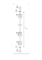
- FIG. 2 is a diagram showing an example of a path (hereinafter referred to as “verified path”) in which connectivity of nodes is verified.
- the verified path 4 is a logical path composed of N generalized nodes 33.
- the number N is an integer of 2 or more, and among the one or more service paths existing in the communication network 3, the maximum number M (maximum number M max ) of network devices constituting the service path is N. It can be taken as the maximum number.
- the generation unit 10 determines the success or failure of the connectivity confirmation test between the respective nodes in the case where one or more failures occur in the verified path 4 with respect to the verified path 4 including the N nodes 33, for each failure point. It is generated in advance as the pattern information 210.
- the generation unit 10 does not have to generate the pattern information of the number that does not exist among the number of network devices that construct the service path existing in the communication network 3.
- the user network interface 31 indicates a connection point between the user network 32 and the service path, and may perform processing such as protocol conversion.
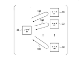
- FIG. 3 is a diagram showing an example of notification of a message when a connectivity confirmation test is executed using the connectivity confirmation protocol for the path to be verified 4.
- Each of the nodes 33 in the verified path 4 serves as a starting point for transmitting the request message.
- the node 33 “#n” (n is any integer from 1 to N inclusive), which is the starting point, is assigned to another node 33 (a message return point) other than its own node in the path to be verified 4.
- a message 100 (request message) is transmitted toward the destination.
- the arrow of the message 100 shown in FIG. 3 visualizes the exchange between the nodes 33.
- the arrow of the message 100 represents a request message from the starting node 33 to the returning node 33 and a response message from the returning node 33 to the starting node 33.
- Send (each request message).
- the node 33 "#n” receives each message 100 (each response message) from the nodes 33 "# 1" to 33 "#N” as a response to the request message.
- the connectivity confirmation test is executed by using all the nodes 33 as the transmission origin of the request message.
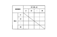
- FIG. 4 is a diagram showing an example of the pattern information 210 of the path to be verified 4 which is composed of N nodes.
- the pattern information 210 is information (pattern information) representing whether or not the node 33 can receive the response message for each combination of the modeled nodes 33 in the path to be verified 4. That is, the pattern information 210 is information indicating whether or not the node 33 at the starting point can receive the response message from the node 33 at the turning point.
- the pattern information 210 is generated in advance for each of one or more failure points in the path to be verified 4. Therefore, the pattern information 210 is associated with one or more failure points.
- the origin node 33 when the origin node 33 can receive the response message from the return point node 33, for example, it is expressed as “G (Good)”. In the pattern information 210, when the origin node 33 cannot receive the response message from the loopback node 33, for example, it is expressed as “NG (No-Good)”. “G (Good)” may be expressed as 0 and “NG (No-Good)” may be expressed as 1. Note that in FIG. 4, the description of “G” and “NG” is omitted, but the data such as “G” and “NG” are described at the location corresponding to the combination of nodes according to the failure location. It The pattern information to be held may be in another data format such as a text format in addition to the table format shown in FIG. Further, the held pattern information may include not only the information shown in FIG. 4 but also other information regarding the path to be verified 4 (for example, topology information indicating the connection relationship between nodes).
- the pattern information 210 represents information on the success / failure result of the connectivity confirmation test for each failure point in the modeled path of the path to be verified 4.
- the estimation device 2 When a failure is detected in a certain service path, the estimation device 2 sends an instruction for a connectivity confirmation test of each network device that constructs the service path, and each network device that has received the instruction causes the estimation device to perform the estimation device.
- the connectivity confirmation test is performed on the network device instructed by 2, and the result is returned to the estimation device 2.
- the ICMP protocol is used as the connectivity confirmation protocol used in the connectivity confirmation test and “ping” is used in the connectivity confirmation test.
- the estimation device 2 detects a failure in the network by an alert or the like, extracts a target service path, and then selects a network device belonging to the service path.
- the estimation apparatus 2 transmits a start command of the operation of transmitting the request message (hereinafter, referred to as “transmission start command”) to the selected network device.
- transmission start command a start command of the operation of transmitting the request message
- the network device Upon receiving the transmission start instruction, the network device transmits the request message to the network device that is the return point of the request message.
- the network device that has received the transmission start command receives a response message to the request message from the network device that is the turning point.
- the processing unit 20 shown in FIG. 1 includes a failure detection unit 200, a device selection unit 201, a command transmission / reception unit 202, and a location estimation unit 203.
- a part or all of the processing unit 20 is realized by a processor such as a CPU executing a program stored in the storage unit 21.
- Some or all of the functional units of the processing unit 20 may be realized by using hardware such as LSI (Large Scale Integration) and ASIC (Application Specific Integrated Circuit).
- the failure detection unit 200 detects the occurrence of a failure in a service path in the communication network 3. For example, when the reception of the data transmitted from the user network 32-1 shown in FIG. 2 times out in the user network 32-2 (system alarm), the failure detection unit 200 generates a failure (possible failure). To detect.
- the device selection unit 201 extracts a service path affected by the failure and includes M network devices forming the service path in the communication network 3. Selected from multiple network devices.
- the device selection unit 201 selects M network devices forming the service path from a plurality of network devices included in the communication network 3. Good.
- the command transmitting / receiving unit 202 sequentially transmits a transmission start command to each selected network device.
- the transmission start instruction may be transmitted simultaneously to some or all of the selected network devices.
- Each network device reports the result of the connection confirmation test executed by the transmission start command to the command transmission / reception unit 202.
- the location estimation unit 203 stores the result of the connection confirmation test in a usable format.
- the location estimation unit 203 changes to the communication network 3 (addition, change or deletion of service path). Or the addition, change, or deletion of network devices) occurs, if the number of network devices in the service path that requires identification of the failure location is less than N, the location estimation unit 203 identifies the failure location. It is possible to estimate. That is, the location estimation unit 203 can continuously perform a test for confirming the connectivity of the network device (a connectivity confirmation test) with respect to the change of the communication network 3 without changing the pattern information. .
- the storage unit 21 is preferably a non-volatile recording medium (non-temporary recording medium) such as a flash memory or an HDD (Hard Disk Drive).
- the storage unit 21 may include a volatile recording medium such as a RAM (Random Access Memory).
- the storage unit 21 stores the pattern information 210 for each failure point in the path to be verified 4.
- the storage unit 21 stores in advance the pattern information 210 of 2 ⁇ 2 size, the pattern information 210 of 3 ⁇ 3 size, ..., And the pattern information 210 of N ⁇ N size.
- the estimation device 2 can make the M network devices 30 A connection relationship similar to the configured service path can be simulated using the path under test 4.
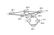
- FIG. 5 is a diagram showing a configuration example of the communication network 3.
- the communication network 3 is composed of eight network devices 30.
- the network device 30 may be a physical node, a logical mode, or a combination of a physical node and a logical node.
- the service path 5-1 that is the first service path is composed of three network devices: a network device 30-1, a network device 30-2, and a network device 30-3.
- the service path 5-2 which is the second service path, is composed of three network devices: the network device 30-6, the network device 30-7, and the network device 30-8.
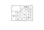
- Each node of the path to be verified 4 is associated with each network device 30 constituting the service path 5 in the communication network 3.
- the location estimating unit 203 associates the verified path 4 and the service path 5 with each other at the stage of comparing the verified path 4 and the service path 5, and estimates the failure location.
- the location estimation unit 203 may store the correspondence information as shown in FIG. 6 in the storage unit in advance and estimate the failure location using the held correspondence information. In this case, the location estimation unit 203 needs to update the correspondence information according to the change of the communication network 3.
- the device selecting unit 201 determines that the network device 30-1, the network device 30-2, and the network device 30-3 that form the service path 5-1. Select.
- FIG. 7 is a diagram showing a first example of a failure location (failure location “A”).
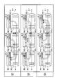
- the network device 30 includes a message transmitting / receiving unit 300, an interface 301, and a switch function unit 302.
- a part or all of the network device 30 is realized by a processor such as a CPU executing a program stored in a storage unit.
- Some or all of the functional units of the network device 30 may be realized by using hardware such as LSI and ASIC.
- the message transmitting / receiving unit 300 is a functional unit (“ping” engine) that transmits / receives a request message and a response message.
- the message transmission / reception unit 300 acquires the transmission start instruction from the instruction transmission / reception unit 202
- the message transmission / reception unit 300 executes “ping” for the instructed network device 30. That is, when the message transmission / reception unit 300 acquires the transmission start command from the command transmission / reception unit 202, the message transmission / reception unit 300 transmits a request message (echo request) to the instructed network device 30. Further, the message transmitting / receiving unit 300 may receive a response message (echo reply) from the network device 30 that has transmitted the request message.
- a request message echo request
- the message transmitting / receiving unit 300 may receive a response message (echo reply) from the network device 30 that has transmitted the request message.
- the interface 301 transfers the request message and the response message to the network device 30 adjacent to the own network device.
- the interface 301 transfers the request message and the response message to the switch function unit 302.
- the switch function unit 302 distributes a request message and a response message addressed to its own network device to its own message transmitting / receiving unit.
- the switch function unit 302 relays a message other than addressed to its own network device to an adjacent network device.
- the switch function unit 302 may perform address conversion or the like by signal processing.
- the interface 303 operates similarly to the interface 301. In addition to the message, the interface 303 and the switch function unit 302 circulate various data transmitted via the service path.
- FIG. 7 an example in which a failure has occurred in the relay of the switch function unit 302-2 of the network device 30-2 is shown as a failure point “A”.
- the command transmission / reception unit 202 transmits a transmission start command to the selected network device 30-1.
- the message transmitting / receiving unit 300-1 of the starting network device 30-1 transmits a request message (for example, an “echo request” message) to the network device 30-2, and sends a response message (for example, an “echo reply” message) to the network device 30-2. It is received from the device 30-2. Even if the request is sent to the network device 30-3, the originating network device 30-1 cannot receive the response message from the network device 30-3 due to a failure.
- a request message for example, an “echo request” message
- a response message for example, an “echo reply” message
- the command transmission / reception unit 202 transmits a transmission start command to the selected network device 30-2.
- the originating network device 30-2 transmits a request message to the network device 30-1 and receives a response message from the network device 30-1.
- the originating network device 30-2 transmits a request message to the network device 30-3 and receives a response message from the network device 30-3.
- the command transceiver 202 transmits a transmission start command to the selected network device 30-3.
- the originating network device 30-3 cannot receive the response message from the network device 30-1 due to a failure even if the request message is transmitted to the network device 30-1.
- the originating network device 30-3 transmits a request message to the network device 30-2 and receives a response message from the network device 30-2.
- FIG. 8 is a diagram showing a second example of a failure location (failure location “B”).
- failure location “B” an example in which a failure has occurred in the interface 303-2 of the network device 30-2 is shown as a failure location “B”.
- the command transmission / reception unit 202 transmits a transmission start command to the selected network device 30-1.
- the message transmitting / receiving unit 300-1 of the origin network device 30-1 transmits a request message to the network device 30-2 and receives a response message from the network device 30-2.
- the originating network device 30-1 cannot receive the response message from the network device 30-3 due to a failure even if the request message is transmitted to the network device 30-3.
- the command transmission / reception unit 202 transmits a transmission start command to the selected network device 30-2.
- the originating network device 30-2 transmits a request message to the network device 30-1 and receives a response message from the network device 30-1. Even if the request is sent to the network device 30-3, the originating network device 30-2 cannot receive the response message from the network device 30-3 due to a failure.
- the command transceiver 202 transmits a transmission start command to the selected network device 30-3.
- the originating network device 30-3 cannot receive the response message from the network device 30-1 due to a failure even if the request message is transmitted to the network device 30-1.
- the originating network device 30-3 cannot receive the response message from the network device 30-2 due to a failure even if the request message is transmitted to the network device 30-2.
- FIG. 9 is a diagram showing the result information of the connection confirmation test in the first example of the failure location (failure location “A” shown in FIG. 6).
- the location estimation unit 203 acquires the pattern information 210 as shown in FIG. 4 from the storage unit 21.
- the location estimation unit 203 shapes (sorts) the result of the connection confirmation test into data in a format in which the topology of the service path and the topology registered as pattern information correspond to each other.
- the corresponding format here means a correspondence relationship as shown in FIG.
- FIG. 10 is a diagram showing an example of the result information in the second example of the failure location (failure location “B” shown in FIG. 7).
- the location estimating unit 203 estimates the failure location in the same procedure as the failure location identification in FIG.
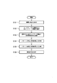
- FIG. 11 is a flowchart showing an operation example of the estimation system 1.
- the failure detection unit 200 detects the occurrence of a failure in the communication network.
- the failure detection unit 200 acquires a failure occurrence report from the operator.
- the failure detection unit 200 may acquire failure occurrence information from a management device that separately manages the network (step S101).
- the device selection unit 201 extracts the service path 5 in which the failure has been detected, and selects the network device 30 that constitutes the service path (step S102). In selecting the network device 30, the device selection unit 201 may acquire information on the network device 30 that constitutes the service path 5 from the management device.
- the device selection unit 201 may acquire the information on the network devices 30 forming the service path 5 before the occurrence of the failure.
- the command transmitting / receiving unit 202 transmits a transmission start command to each selected network device 30, and receives the result of the connectivity confirmation test corresponding to the transmission start command from each network device (step S103).
- the location estimation unit 203 collects and shapes the results (reception results) of the connectivity confirmation test.
- the location estimation unit 203 acquires the pattern information 210 of “N” nodes 33, which is equal to the number “M” of the network devices 30 configuring the service path 5 (step S104). Note that when the pattern information 210 is obtained, only “N” pattern information 210 having the same topology as the network topology of the service path 5 may be acquired.
- the location estimation unit 203 compares the result of the connectivity confirmation test with the acquired pattern information 210 for each failure location (step S105).
- the location estimating unit 203 estimates the failure location associated with the pattern information 210 that matches the result of the connectivity confirmation test as the failure location in the service path 5 (step S106).
- the network device 30 that is the return point of the request message may send a response message to the network device 30 that is the starting point, or may send a response message to the estimation device 2.
- the estimation device 2 estimates (specifies) the failure point in the service path 5 based on the result of comparison between the pattern information and the result information indicating whether or not the network device 30 has actually received the response message.
- the estimation device 2 of the embodiment estimates a failure point in the service path 5 which is a communication line or a communication path configured in the communication network 3.
- the estimation device 2 includes a generation unit 10, a device selection unit 201, a command transmission / reception unit 202, and a location estimation unit 203.
- the generation unit 10 determines whether or not the connectivity confirmation test between the nodes 33 is successful when one or more failures occur in the path to be verified 4 configured of “N (N is 2 or more)” nodes.
- the pattern information 210 is generated in advance for each location.
- the device selection unit 201 selects “M (M is 2 or more)” network devices 30 forming the service path 5 from the plurality of network devices 30 in the communication network 3 according to the occurrence of a failure. .
- the command transmission / reception unit 202 executes a connectivity confirmation test between the selected network devices 30.
- the estimation device 2 of the embodiment can estimate the failure location based on the pattern information 210 without changing the comparison network information and the comparison program according to the change of the communication network 3. .
- the first network device 30 configuring the service path 5 transmits a request message to the second network device 30 configuring the service path 5 in the connectivity confirmation test.
- the second network device 30 transmits a response message to the first network device 30 in the connectivity confirmation test.
- the first network device 30 transmits the reception result of the response message to the estimation device 2.
- the second network device 30 may send a response message to the estimation device 2 instead of sending a response message to the first network device 30.
- the estimation device 2 can estimate the failure location based on the response message.
- the pattern information in the modeled path to be verified is generated and stored in advance, so that the same pattern information can be applied to a plurality of service paths to estimate the failure location. Is. As a result, the number of pattern information 210 (patterns) stored in the storage unit 21 in advance is suppressed.
- the estimation device 2 is a command of the Internet control notification protocol that checks the route of the communication network instead of the “ping” command.
- the “traceroute” command may be used.
- the estimation device 2 determines not only the continuity (connectivity) from the starting point network device 30 to the turning point network device 30 but also from the starting point network device 30 to the turning point network device 30. It is also possible to check the continuity (connectivity) of the relay network device 30 up to. As a result, the estimation device 2 can reduce the procedure required to confirm the continuity between the network devices 30, as compared with the case where the “ping” command is used. Further, the connectivity confirmation test may be performed using another protocol other than ICMP.
- the device of the present invention can be realized by a computer and a program, and the program can be recorded in a recording medium or provided through a network.
- the estimating device and the network device (node) in the above-described embodiment may be realized by a computer.
- a program for realizing this function may be recorded in a computer-readable recording medium, and the program recorded in this recording medium may be read by a computer system and executed.
- the “computer system” mentioned here includes an OS and hardware such as peripheral devices.
- the "computer-readable recording medium” refers to a portable medium such as a flexible disk, a magneto-optical disk, a ROM, a CD-ROM, or a storage device such as a hard disk built in a computer system.
- the "computer-readable recording medium” means to hold a program dynamically for a short time like a communication line when transmitting the program through a network such as the Internet or a communication line such as a telephone line.
- a volatile memory inside a computer system that serves as a server or a client in that case may hold a program for a certain period of time.
- the program may be for realizing a part of the functions described above, and may be a program that can realize the functions described above in combination with a program already recorded in a computer system, It may be realized using a programmable logic device such as FPGA (Field Programmable Gate Array).
- the present invention is applicable to communication systems.
Landscapes
- Engineering & Computer Science (AREA)
- Computer Networks & Wireless Communication (AREA)
- Signal Processing (AREA)
- Health & Medical Sciences (AREA)
- Cardiology (AREA)
- General Health & Medical Sciences (AREA)
- Data Exchanges In Wide-Area Networks (AREA)
Abstract
推定方法は、「N」台のノードから構成される被検証パスに障害が発生した場合におけるノードの間の接続性確認試験の成否を障害箇所ごとにパターン情報として生成する生成ステップと、複数のネットワーク機器のうちから、「M」台のネットワーク機器を、障害の発生に応じて選択するステップと、選択されたネットワーク機器の間で接続性確認試験を実行するステップと、接続性確認試験の確認結果と、パターン情報のうちで「N=M」となるパターン情報とを比較するステップと、「N=M」となるパターン情報と確認結果とが一致した場合、パターン情報に対応付けられた障害箇所に基づいてサービス・パス内の障害箇所を推定するステップとを有する。
Description
本発明は、推定方法、推定装置及び推定プログラムに関する。
通信ネットワークに構成される通信回線又は通信パス(以下「サービス・パス」という。)に障害が発生した場合、障害の発生箇所(以下「障害箇所」という。)を推定することは重要である。オペレータは、RFC(Request for comments)792及びRFC4443(非特許文献1及び2参照)によって規定されたインターネット制御通知プロトコル(ICMP: Internet Control Message Protocol)を利用して、障害箇所を推定する場合がある。
サービス・パスにおいて障害が発生した場合、オペレータは、例えばインターネット制御通知プロトコルの「ping」の送信命令を、管理装置に入力する。管理装置は、「ping」の送信命令が入力された場合、要求メッセージ(例えば、「echo request」メッセージ)をネットワーク機器に送信し、応答メッセージ(例えば、「echo reply」メッセージ)を、そのネットワーク機器から受信する。
管理装置は、オペレータから入力された「ping」の送信命令に応じて、要求メッセージの送信先を変更する。このようにして、オペレータは、管理装置が応答メッセージを要求メッセージの送信先から受信できたか否かに基づいて、管理装置とネットワーク機器との導通(接続性)を確認する。
オペレータは、管理装置が応答メッセージをネットワーク機器から受信できたか否かに基づいて、サービス・パスにおける障害箇所を推定する。しかしながら、オペレータは、障害箇所の推定を誤ることがある。特に、通信ネットワークに含まれているネットワーク機器が多い場合、オペレータは、障害箇所の推定を誤ることが多い。そこで、オペレータの人手による切り分けではなく、障害箇所を自動で推定する推定装置が試みられている(特許文献1参照)。
RFC792, "Internet Control Message Protocol - DARPA Internet Program - Protocol Specification", September 1981
RFC4443, "Internet Control Message Protocol (ICMPv6) for the Internet Protocol Version 6 (IPv6) Specification", March 2006
推定装置は、応答メッセージをネットワーク機器等が実際に受信できたか否かを表す結果情報と、実際のネットワーク情報(装置、トポロジ等)との比較結果に基づいて、障害箇所を推定する場合がある。ネットワークに変更があった場合には、その変更の都度、比較対象となる実際のネットワーク情報(以下「比較用ネットワーク情報」という)の修正と、比較用プログラム(比較アルゴリズム)の変更とが必要となる。このように、従来の推定装置は、通信ネットワークの変更(例えば、サービス・パスの削除、追加及び変更等、ネットワーク機器の撤去、追加及び変更等)に応じて比較用ネットワーク情報及び比較用プログラムを変更しなければ、障害箇所を推定することができないという問題があった。通信ネットワークの変更は頻繁に生じることも多く、また通信ネットワークに対応するネットワーク情報は複雑かつ膨大となる傾向にある。
上記事情に鑑み、本発明は、通信ネットワークの変更に応じて比較用ネットワーク情報及び比較用プログラムを変更することなく、障害箇所を推定することが可能である推定方法、推定装置及び推定プログラムを提供することを目的としている。
本発明の一態様は、通信ネットワークに構成される通信回線又は通信パスであるサービス・パス内の障害箇所を推定する推定装置が実行する推定方法であって、「N(Nは2以上)」台のノードから構成される被検証パスに1箇所以上の障害が発生した場合における前記ノードの間の接続性確認試験の成否を障害箇所ごとにパターン情報として予め生成するパターン生成ステップと、前記通信ネットワークにおける複数のネットワーク機器のうちから、前記サービス・パスを構成する「M(Mは2以上)」台の前記ネットワーク機器を、前記障害の発生に応じて選択するステップと、選択された前記ネットワーク機器の間で前記接続性確認試験を実行するステップと、前記接続性確認試験の確認結果と、予め生成された前記パターン情報のうちで「N=M」となる前記パターン情報とを比較するステップと、「N=M」となる前記パターン情報と前記確認結果とが一致した場合、「N=M」となる前記パターン情報に対応付けられた前記障害箇所に基づいて前記サービス・パス内の障害箇所を推定するステップとを有する推定方法である。
本発明の一態様は、上記の推定方法であって、前記被検証パスの前記ノードの台数は、前記通信ネットワークに構成される複数の前記サービス・パスのうち、最大台数の前記ネットワーク機器から構成される前記サービス・パスの前記ネットワーク機器の台数よりも多い台数である。
本発明の一態様は、上記の推定方法であって、前記サービス・パスを構成する第1の前記ネットワーク機器は、前記接続性確認試験において、前記サービス・パスを構成する第2の前記ネットワーク機器に対して要求メッセージを送信する。
本発明の一態様は、上記の推定方法であって、前記サービス・パスを構成する第2の前記ネットワーク機器は、前記接続性確認試験において、前記サービス・パスを構成する第1の前記ネットワーク機器、又は、前記推定装置に対して応答メッセージを送信する。
本発明の一態様は、上記の推定方法であって、前記要求メッセージは、インターネット制御通知プロトコル(ICMP)を利用するping又はtracerouteのメッセージである。
本発明の一態様は、上記の推定方法であって、前記ネットワーク機器は、前記通信ネットワークにおける、物理的なノードと論理的なノードとのうちの少なくとも一方である。
本発明の一態様は、通信ネットワークに構成される通信回線又は通信パスであるサービス・パス内の障害箇所を推定する推定装置であって、「N(Nは2以上)」台のノードから構成される被検証パスに1箇所以上の障害が発生した場合における前記ノードの間の接続性確認試験の成否を障害箇所ごとにパターン情報として予め生成する生成部と、前記通信ネットワークにおける複数のネットワーク機器のうちから、前記サービス・パスを構成する「M(Mは2以上)」台の前記ネットワーク機器を、前記障害の発生に応じて選択する機器選択部と、選択された前記ネットワーク機器の間で前記接続性確認試験を実行する命令送受信部と、前記接続性確認試験の確認結果と、予め生成された前記パターン情報のうちで「N=M」となる前記パターン情報とを比較し、「N=M」となる前記パターン情報と前記確認結果とが一致した場合、「N=M」となる前記パターン情報に対応付けられた前記障害箇所に基づいて前記サービス・パス内の障害箇所を推定する箇所推定部とを備える推定装置である。
本発明の一態様は、上記の推定方法をコンピュータに実行させるための推定プログラムである。
本発明により、通信ネットワークの変更に応じて比較用ネットワーク情報及び比較用プログラムを変更することなく、障害箇所を推定することが可能である。
本発明の実施形態について、図面を参照して詳細に説明する。
図1は、推定システム1の構成例を示す図である。推定システム1は、通信ネットワークにおいて障害箇所を推定するシステムである。推定システム1は、推定装置2と、通信ネットワーク3とを備える。推定装置2は、通信ネットワークにおける障害箇所を推定する情報処理装置である。推定装置2は、生成部10と、処理部20と、記憶部21とを備える。生成部10の一部又は全部は、CPU(Central Processing Unit)等のプロセッサが、記憶部21に記憶されたプログラムを実行することにより実現される。
図1は、推定システム1の構成例を示す図である。推定システム1は、通信ネットワークにおいて障害箇所を推定するシステムである。推定システム1は、推定装置2と、通信ネットワーク3とを備える。推定装置2は、通信ネットワークにおける障害箇所を推定する情報処理装置である。推定装置2は、生成部10と、処理部20と、記憶部21とを備える。生成部10の一部又は全部は、CPU(Central Processing Unit)等のプロセッサが、記憶部21に記憶されたプログラムを実行することにより実現される。
通信ネットワーク3は、通信サービスを提供するネットワークである。通信ネットワーク3は、複数のネットワーク機器を備える。ネットワーク機器は、例えば、ルータ及びスイッチである。以下、サービス・パスを構成するネットワーク機器の台数を「M」と表記する。
次に、通信ネットワーク3のモデルを用いたシミュレーションによるパターン情報の生成について、図2から図4までを用いて説明する。
図2は、ノードの接続性が検証されるパス(以下「被検証パス」という。)の例を示す図である。被検証パス4は、N台の一般化されたノード33から構成される論理パスである。台数Nは、2以上の整数であり、通信ネットワーク3において存在する1以上のサービス・パスのうちで、サービス・パスを構成するネットワーク機器の台数Mの最大数(最大台数Mmax)をNの最大数として取りうる。生成部10は、N台のノード33で構成される被検証パス4に関して、被検証パスに1箇所以上の障害が発生した場合における各ノード間の接続性確認試験の成否を、障害箇所ごとにパターン情報210として予め生成する。なお、N=2からN=Mmaxのそれぞれの場合における被検証パスのパターン情報が生成される。ただし、記憶容量削減のため、生成部10は、通信ネットワーク3に存在するサービス・パスを構築するネットワーク機器の台数のうちで存在しない台数のパターン情報を生成しなくてもよい。頻繁に発生するネットワーク変更に対応するため、Nは、N=2から、N=(Mmax+α)まででもよい(αは1以上の自然数)。
ユーザー網インタフェース31は、ユーザー網32とサービス・パスとの間の接続点を示すものであり、プロトコル変換などの処理を行ってもよい。
図3は、被検証パス4について接続性確認プロトコルを用いて接続性確認試験を実行する際のメッセージの通知例を示す図である。被検証パス4におけるノード33は、それぞれ要求メッセージの送信の起点となる。図3では、起点となったノード33「#n」(nは、1以上N以下のいずれかの整数)は、被検証パス4における自ノード以外の他のノード33(メッセージの折り返し点)に向けて、メッセージ100(要求メッセージ)を送信する。図3に示されたメッセージ100の矢印は、ノード33の間のやりとりを可視化したものである。メッセージ100の矢印は、起点のノード33から折り返しのノード33への要求メッセージと、折り返しのノード33から起点のノード33への応答メッセージとを表す。
図3では、メッセージ100の起点であるノード33「#n」は、自ノードを除くメッセージ100の折り返し点であるノード33「#1」~ノード33「#N」)に向けて、各メッセージ100(各要求メッセージ)を送信する。ノード33「#n」は、ノード33「#1」~ノード33「#N」から、各メッセージ100(各応答メッセージ)を要求メッセージの応答として受信する。接続性確認試験は、全てのノード33を要求メッセージの送信起点として実行される。
図4は、N台のノードで構成される被検証パス4のパターン情報210の例を示す図である。パターン情報210は、応答メッセージをノード33が受信可能であるか否かを、被検証パス4におけるモデル化されたノード33の組み合わせごとに表す情報(パターン情報)である。すなわち、パターン情報210は、起点のノード33が応答メッセージを折り返し点のノード33から受信可能であるか否かを表す情報である。
被検証パス4における障害箇所は、複数(多重障害)でもよい。パターン情報210は、被検証パス4における1以上の障害箇所ごとに予め生成される。したがって、パターン情報210は、1以上の障害箇所に対応付けられている。
パターン情報210では、起点のノード33が応答メッセージを折り返し点のノード33から受信可能である場合に、例えば「G(Good)」と表現される。パターン情報210では、起点のノード33が応答メッセージを折り返し点のノード33から受信可能でない場合に、例えば「NG(No-Good)」と表現される。「G(Good)」は0と表現され、「NG(No-Good)」は1と表現されてもよい。なお、図4では、「G」、「NG」の記載が省略されているが、「G」及び「NG」などのデータは、故障箇所に応じて、ノードの組み合わせに対応する箇所に記載される。なお、保持されるパターン情報は、図4に示されているような表形式だけでなく、テキスト形式など別のデータ形式でも良い。また、保持されるパターン情報に図4に示す情報だけでなく、被検証パス4に関する他の情報(例えば、ノード間の接続関係を示すトポロジ情報)を含んでもよい。
このように、パターン情報210は、被検証パス4のモデル化されたパスにおける故障箇所ごとに、接続性確認試験の成否結果の情報を表す。
次に、実際の通信ネットワーク3におけるサービス・パスに対して接続性確認試験を実行する場合について説明する。
あるサービス・パスに障害の発生が検知された場合について、推定装置2は、サービス・パスを構築する各ネットワーク機器の接続性確認試験の指示を送付し、指示を受信した各ネットワーク機器は推定装置2より指示されたネットワーク機器へ接続性確認試験を実施し、その結果を推定装置2へと返す。本実施形態では、接続性確認試験で用いる接続性確認プロトコルとしてICMPプロトコルを用い、接続性確認試験に「ping」を用いた場合について説明を行う。推定装置2は、アラートなどによりネットワーク内の障害を検知し、対象となるサービス・パスの抽出後、サービス・パスに属するネットワーク機器を選択する。推定装置2は、要求メッセージを送信する動作の開始命令(以下「送信開始命令」という。)を、選択されたネットワーク機器に送信する。送信開始命令を受けたネットワーク機器は、要求メッセージの折り返し点となるネットワーク機器に対して、要求メッセージを送信する。送信開始命令を受けたネットワーク機器は、折り返し点となったネットワーク機器から、要求メッセージに対する応答メッセージを受信する。
図1に示された処理部20は、障害検知部200と、機器選択部201と、命令送受信部202と、箇所推定部203とを備える。処理部20の一部又は全部は、CPU等のプロセッサが、記憶部21に記憶されたプログラムを実行することにより実現される。処理部20の各機能部のうち一部又は全部は、例えば、LSI(Large Scale Integration)やASIC(Application Specific Integrated Circuit)等のハードウェアを用いて実現されてもよい。
障害検知部200は、通信ネットワーク3内のサービス・パスにおける障害の発生を検知する。障害検知部200は、例えば、図2に示されたユーザー網32-1から送信されたデータの受信がユーザー網32-2においてタイムアウトした場合(システム警報)、障害の発生(障害の可能性)を検知する。
機器選択部201は、通信ネットワーク3における障害の発生が検知された場合、障害の影響を受けるサービス・パスを抽出し、サービス・パスを構成するM台のネットワーク機器を、通信ネットワーク3に含まれている複数のネットワーク機器から選択する。
機器選択部201は、「ping」の送信命令がオペレータによって入力された場合、サービス・パスを構成するM台のネットワーク機器を、通信ネットワーク3に含まれている複数のネットワーク機器から選択してもよい。
命令送受信部202は、選択された各ネットワーク機器に対して、送信開始命令を順に送信する。なお、送信開始命令は、一部又は全ての選択されたネットワーク機器に対して同時に送信されてもよい。各ネットワーク機器は、送信開始命令によって実行された接続確認試験の結果を、命令送受信部202へ報告する。箇所推定部203は、利用可能な形式で、接続確認試験の結果を記憶する。
箇所推定部203は、記憶部21に保持されるパターン情報210の内「N=M」となるパターン情報と、機器選択部201によって選択された各ネットワーク機器が報告した接続性確認試験との比較結果に基づいて、サービス・パスにおける障害箇所を推定する。
「N>Mmax」の条件でパターン情報を予め生成し、記憶部21にパターン情報が保持されていた場合、箇所推定部203は、通信ネットワーク3に変更(サービス・パスの追加、変更又は削除や、ネットワーク機器の追加、変更又は削除など)が生じた場合でも、障害箇所の特定が必要なサービス・パスのネットワーク機器の台数がNより少ない場合には、箇所推定部203は、障害箇所を推定することが可能である。すなわち、箇所推定部203は、通信ネットワーク3の変更に対して、ネットワーク機器の接続性を確認する試験(接続性確認試験)を、パターン情報の変更なしに継続的に実行することが可能である。
記憶部21は、例えばフラッシュメモリ、HDD(Hard Disk Drive)などの不揮発性の記録媒体(非一時的な記録媒体)が好ましい。記憶部21は、RAM(Random AccessMemory)などの揮発性の記録媒体を備えてもよい。記憶部21は、被検証パス4における障害箇所ごとに、パターン情報210を記憶する。記憶部21は、2×2のサイズのパターン情報210と、3×3のサイズのパターン情報210と、…、N×Nのサイズのパターン情報210とを予め記憶する。
次に、実際の通信ネットワーク3について障害箇所を推定する処理の詳細を説明する。
試験対象となるサービス・パスを構成する各ネットワーク機器を、一般化された各ノード(モデル上の各ノード)のそれぞれに、推定において対応付けることで、推定装置2は、M台のネットワーク機器30から構成されるサービス・パスと同様の接続関係を、被検証パス4を用いて模擬することができる。
試験対象となるサービス・パスを構成する各ネットワーク機器を、一般化された各ノード(モデル上の各ノード)のそれぞれに、推定において対応付けることで、推定装置2は、M台のネットワーク機器30から構成されるサービス・パスと同様の接続関係を、被検証パス4を用いて模擬することができる。
図5は、通信ネットワーク3の構成例を示す図である。図5では、通信ネットワーク3は、8台のネットワーク機器30で構成される。ネットワーク機器30は、物理的ノードでもよいし、論理的モードでもよいし、物理的ノード及び論理的ノードの組み合わせでもよい。第1のサービス・パスであるサービス・パス5-1は、ネットワーク機器30-1と、ネットワーク機器30-2と、ネットワーク機器30-3との3台のネットワーク機器で構成される。第2のサービス・パスであるサービス・パス5-2は、ネットワーク機器30-6と、ネットワーク機器30-7と、ネットワーク機器30-8との3台のネットワーク機器で構成される。
図6は、パターン情報として生成されている「N=3」の被検証パス4の各ノード33と、各サービス・パス5を構成するネットワーク機器30との対応関係の例を示す図である。被検証パス4の各ノードは、通信ネットワーク3におけるサービス・パス5を構成する各ネットワーク機器30に対応付けられる。なお、箇所推定部203は、被検証パス4とサービス・パス5とを比較する段階で被検証パス4とサービス・パス5とを対応付けて、障害箇所を推定する。箇所推定部203は、図6のような対応情報を事前に記憶部に保持し、保持された対応情報を用いて障害箇所を推定してもよい。この場合、箇所推定部203は、通信ネットワーク3の変更に応じて対応情報を最新化する必要がある。
機器選択部201は、例えばサービス・パス5-1における障害の発生が検知された場合、サービス・パス5-1を構成するネットワーク機器30-1とネットワーク機器30-2とネットワーク機器30-3とを選択する。
以下では、サービス・パス5-1に障害が発生した場合における故障箇所特定について説明する。
図7は、障害箇所の第1例(障害箇所「A」)を示す図である。ネットワーク機器30は、メッセージ送受信部300と、インタフェース301と、スイッチ機能部302とを備える。ネットワーク機器30の一部又は全部は、CPU等のプロセッサが、記憶部に記憶されたプログラムを実行することにより実現される。ネットワーク機器30の各機能部のうち一部又は全部は、例えば、LSIやASIC等のハードウェアを用いて実現されてもよい。
メッセージ送受信部300は、要求メッセージの送受信と、応答メッセージの送受信とを行う機能部(「ping」エンジン)である。メッセージ送受信部300は、送信開始命令を命令送受信部202から取得した場合、指示されたネットワーク機器30に対して「ping」を実行する。すなわち、メッセージ送受信部300は、送信開始命令を命令送受信部202から取得した場合、指示されたネットワーク機器30に対して要求メッセージ(echo request)を送信する。また、メッセージ送受信部300は、要求メッセージを送信したネットワーク機器30から応答メッセージ(echo reply)を受信してもよい。
インタフェース301は、要求メッセージ及び応答メッセージを、自ネットワーク機器に隣接するネットワーク機器30に転送する。インタフェース301は、要求メッセージ及び応答メッセージを、スイッチ機能部302に転送する。スイッチ機能部302は、自ネットワーク機器宛ての要求メッセージ及び応答メッセージを、自身のメッセージ送受信部へと振り分ける。スイッチ機能部302は、自ネットワーク機器宛て以外のメッセージを、隣接するネットワーク機器へと中継する。なお、スイッチ機能部302は、信号処理により、アドレス変換などを行ってもよい。インタフェース303は、インタフェース301と同様に動作する。なお、インタフェース303及びスイッチ機能部302には、メッセージ以外にも、サービス・パスを経由して伝送される様々なデータが流通される。
図7には、ネットワーク機器30-2のスイッチ機能部302-2の中継に障害が発生した例が、障害箇所「A」として示されている。命令送受信部202は、選択されたネットワーク機器30-1に送信開始命令を送信する。起点のネットワーク機器30-1のメッセージ送受信部300-1は、要求メッセージ(例えば、「echo request」メッセージ)をネットワーク機器30-2に送信し、応答メッセージ(例えば、「echo reply」メッセージ)をネットワーク機器30-2から受信する。起点のネットワーク機器30-1は、要求メッセージをネットワーク機器30-3に送信しても、障害のため応答メッセージをネットワーク機器30-3から受信できない。
次に、命令送受信部202は、選択されたネットワーク機器30-2に送信開始命令を送信する。起点のネットワーク機器30-2は、要求メッセージをネットワーク機器30-1に送信し、応答メッセージをネットワーク機器30-1から受信する。起点のネットワーク機器30-2は、要求メッセージをネットワーク機器30-3に送信し、応答メッセージをネットワーク機器30-3から受信する。
最後に、命令送受信部202は、選択されたネットワーク機器30-3に送信開始命令を送信する。起点のネットワーク機器30-3は、要求メッセージをネットワーク機器30-1に送信しても、障害のため、応答メッセージをネットワーク機器30-1から受信できない。起点のネットワーク機器30-3は、要求メッセージをネットワーク機器30-2に送信し、応答メッセージをネットワーク機器30-2から受信する。
図8は、障害箇所の第2例(障害箇所「B」)を示す図である。図8には、ネットワーク機器30-2のインタフェース303-2に障害が発生した例が、障害箇所「B」として示されている。命令送受信部202は、選択されたネットワーク機器30-1に送信開始命令を送信する。起点のネットワーク機器30-1のメッセージ送受信部300-1は、要求メッセージをネットワーク機器30-2に送信し、応答メッセージをネットワーク機器30-2から受信する。起点のネットワーク機器30-1は、要求メッセージをネットワーク機器30-3に送信しても、障害のため、応答メッセージをネットワーク機器30-3から受信できない。
次に、命令送受信部202は、選択されたネットワーク機器30-2に送信開始命令を送信する。起点のネットワーク機器30-2は、要求メッセージをネットワーク機器30-1に送信し、応答メッセージをネットワーク機器30-1から受信する。起点のネットワーク機器30-2は、要求メッセージをネットワーク機器30-3に送信しても、障害のため、応答メッセージをネットワーク機器30-3から受信できない。
最後に、命令送受信部202は、選択されたネットワーク機器30-3に送信開始命令を送信する。起点のネットワーク機器30-3は、要求メッセージをネットワーク機器30-1に送信しても、障害のため、応答メッセージをネットワーク機器30-1から受信できない。起点のネットワーク機器30-3は、要求メッセージをネットワーク機器30-2に送信しても、障害のため、応答メッセージをネットワーク機器30-2から受信できない。
図9は、障害箇所の第1例(図6に示された障害箇所「A」)における接続確認試験の結果情報を示す図である。箇所推定部203は、図4に示されたようなパターン情報210を、記憶部21から取得する。箇所推定部203は、サービス・パス5-1を構成するネットワーク機器の台数「M=3」に合わせて、「N=3」のパターン情報210を、記憶部21から取得する。箇所推定部203は、サービス・パスのトポロジとパターン情報として登録されているトポロジとが対応する形式のデータに、接続確認試験の結果を整形(並び替え)する。ここでの対応する形式とは、図6に示すような対応関係のことである。次に、箇所推定部203は、接続確認試験の結果と取得された「N=3」のパターン情報とを比較する。
箇所推定部203は、比較の結果、ノード「#2」の中継部の障害を示す「N=3」のパターン情報と接続確認試験の結果とが一致することから、サービス・パス5-1における対応するネットワーク機器30-2のスイッチ機能部302(障害箇所「A」)における中継機能障害であると推定する。
図10は、障害箇所の第2例(図7に示された障害箇所「B」)における結果情報の例を示す図である。箇所推定部203は、図9の故障箇所特定と同様の手順で、故障箇所を推定する。箇所推定部203は、パターン情報と接続性確認試験の結果とを比較する。箇所推定部203は、ノード「#2」及びノード「#3」の間の障害を示す「N=3」のパターン情報と接続性確認試験の結果とが一致することから、各ノードにサービス・パス5-1において対応するネットワーク機器30-2及びネットワーク機器30-3の間(障害箇所「B」)のリンク障害であると推定する。
次に、推定システム1の動作例を説明する。
図11は、推定システム1の動作例を示すフローチャートである。障害検知部200は、通信ネットワークにおける障害発生を検知する。ここで、障害検知部200は、オペレータから、障害発生の申告を取得する。障害検知部200は、別途ネットワークを管理する管理装置から、障害発生の情報を取得してもよい(ステップS101)。機器選択部201は、障害の発生が検知されたサービス・パス5を抽出し、サービス・パスを構成するネットワーク機器30を選択する(ステップS102)。なお、ネットワーク機器30の選択にあたり、機器選択部201は、サービス・パス5を構成するネットワーク機器30の情報を管理装置から取得してもよい。機器選択部201は、サービス・パス5を構成するネットワーク機器30の情報を、障害の発生前に取得しても良い。
図11は、推定システム1の動作例を示すフローチャートである。障害検知部200は、通信ネットワークにおける障害発生を検知する。ここで、障害検知部200は、オペレータから、障害発生の申告を取得する。障害検知部200は、別途ネットワークを管理する管理装置から、障害発生の情報を取得してもよい(ステップS101)。機器選択部201は、障害の発生が検知されたサービス・パス5を抽出し、サービス・パスを構成するネットワーク機器30を選択する(ステップS102)。なお、ネットワーク機器30の選択にあたり、機器選択部201は、サービス・パス5を構成するネットワーク機器30の情報を管理装置から取得してもよい。機器選択部201は、サービス・パス5を構成するネットワーク機器30の情報を、障害の発生前に取得しても良い。
命令送受信部202は、選択された各ネットワーク機器30に送信開始命令を送信し、その送信開始命令に応じた接続性確認試験の結果を各ネットワーク機器から受信する(ステップS103)。箇所推定部203は、接続性確認試験の結果(受信結果)を集約及び整形する。箇所推定部203は、サービス・パス5を構成するネットワーク機器30の台数「M」に等しい「N」台のノード33のパターン情報210を取得する(ステップS104)。なお、パターン情報210の所得の際に、サービス・パス5のネットワークトポロジと同一のトポロジを有する「N」台のパターン情報210のみを取得してもよい。
箇所推定部203は、接続性確認試験の結果と取得されたパターン情報210とを、故障箇所ごとに比較する(ステップS105)。
箇所推定部203は、接続性確認試験の結果に一致するパターン情報210に対応付けられている障害箇所を、サービス・パス5における障害箇所と推定する(ステップS106)。
なお、要求メッセージの折り返し点となったネットワーク機器30は、起点となったネットワーク機器30に対して応答メッセージを送信してもよいし、推定装置2に対して応答メッセージを送信してもよい。推定装置2は、応答メッセージをネットワーク機器30が実際に受信できたか否かを表す結果情報とパターン情報との比較結果に基づいて、サービス・パス5における障害箇所を推定(特定)する。
以上のように、実施形態の推定装置2は、通信ネットワーク3に構成される通信回線又は通信パスであるサービス・パス5内の障害箇所を推定する。推定装置2は、生成部10と、機器選択部201と、命令送受信部202と、箇所推定部203とを備える。生成部10は、「N(Nは2以上)」台のノードから構成される被検証パス4に1箇所以上の障害が発生した場合におけるノード33の間の接続性確認試験の成否を、障害箇所ごとにパターン情報210として予め生成する。機器選択部201は、通信ネットワーク3における複数のネットワーク機器30のうちから、サービス・パス5を構成する「M(Mは2以上)」台のネットワーク機器30を、障害の発生に応じて選択する。命令送受信部202は、選択されたネットワーク機器30の間で、接続性確認試験を実行する。箇所推定部203は、接続性確認試験の確認結果と、予め生成されたパターン情報210のうちで「N=M」となるパターン情報とを比較する。箇所推定部203は、「N=M」となるパターン情報と確認結果とが一致した場合、「N=M」となるパターン情報に対応付けられた障害箇所に基づいて、サービス・パス5内の障害箇所を推定する。
これによって、実施形態の推定装置2は、通信ネットワーク3の変更に応じて比較用ネットワーク情報及び比較用プログラムを変更することなく、パターン情報210に基づいて、障害箇所を推定することが可能である。
サービス・パス5を構成する第1のネットワーク機器30は、接続性確認試験において、サービス・パス5を構成する第2のネットワーク機器30に対して、要求メッセージを送信する。第2のネットワーク機器30は、接続性確認試験において、第1のネットワーク機器30に対して応答メッセージを送信する。第1のネットワーク機器30は、応答メッセージの受信結果を推定装置2に対して送信する。第2のネットワーク機器30は、接続性確認試験において、第1のネットワーク機器30に対して応答メッセージを送信する代わりに、推定装置2に対して応答メッセージを送信してもよい。これによって、推定装置2は、応答メッセージに基づいて障害箇所を推定することが可能である。
サービス・パス5ごとの障害箇所と応答メッセージの結果情報との単純な対応付けの結果は複雑であり、それらの対応付けの数(組み合わせ)は膨大である。本発明では、モデル化した被検証パスにおけるパターン情報を事前に生成・記憶しておくことで、複数のサービス・パスに対して、同じパターン情報を適用して障害箇所の推定を行うことが可能である。これにより、記憶部21に予め記憶されるパターン情報210(パターン)の数は抑制される。
以上、この発明の実施形態について図面を参照して詳述してきたが、具体的な構成はこの実施形態に限られるものではなく、この発明の要旨を逸脱しない範囲の設計等も含まれる。
例えば、上述の実施形態では、「ping」コマンドが用いられた例を説明したが、推定装置2は、「ping」コマンドの代わりに、通信ネットワークの経路を調べるインターネット制御通知プロトコルのコマンドである「traceroute」コマンドを用いてもよい。「traceroute」コマンドが用いられた場合、推定装置2は、起点のネットワーク機器30から折り返し点のネットワーク機器30までの導通(接続性)だけでなく、起点のネットワーク機器30から折り返し点のネットワーク機器30までの中継のネットワーク機器30の導通(接続性)も確認することができる。これによって、推定装置2は、「ping」コマンドが用いられた場合と比較して、各ネットワーク機器30の間の導通の確認に要する手順を削減することができる。また、ICMP以外の別のプロトコルを用いて、接続性確認試験を実施してもよい。
本発明の装置はコンピュータとプログラムによっても実現でき、プログラムを記録媒体に記録することも、ネットワークを通して提供することも可能である。
すなわち、上述した実施形態における推定装置、ネットワーク機器(ノード)をコンピュータで実現するようにしてもよい。その場合、この機能を実現するためのプログラムをコンピュータ読み取り可能な記録媒体に記録して、この記録媒体に記録されたプログラムをコンピュータシステムに読み込ませ、実行することによって実現してもよい。なお、ここでいう「コンピュータシステム」とは、OSや周辺機器等のハードウェアを含むものとする。また、「コンピュータ読み取り可能な記録媒体」とは、フレキシブルディスク、光磁気ディスク、ROM、CD-ROM等の可搬媒体、コンピュータシステムに内蔵されるハードディスク等の記憶装置のことをいう。さらに「コンピュータ読み取り可能な記録媒体」とは、インターネット等のネットワークや電話回線等の通信回線を介してプログラムを送信する場合の通信線のように、短時間の間、動的にプログラムを保持するもの、その場合のサーバやクライアントとなるコンピュータシステム内部の揮発性メモリのように、一定時間プログラムを保持しているものも含んでもよい。また上記プログラムは、前述した機能の一部を実現するためのものであってもよく、さらに前述した機能をコンピュータシステムにすでに記録されているプログラムとの組み合わせで実現できるものであってもよく、FPGA(Field Programmable Gate Array)等のプログラマブルロジックデバイスを用いて実現されるものであってもよい。
本発明は、通信システムに適用可能である。
1…推定システム、2…推定装置、3…通信ネットワーク、4…被検証パス、5…サービス・パス、10…生成部、20…処理部、21…記憶部、30…ネットワーク機器、31…ユーザー網インタフェース、32…ユーザー網、33…ノード、100…メッセージ、200…障害検知部、201…機器選択部、202…命令送受信部、203…箇所推定部、210…パターン情報、300…メッセージ送受信部、301…インタフェース、302…スイッチ機能部、303…インタフェース
Claims (8)
- 通信ネットワークに構成される通信回線又は通信パスであるサービス・パス内の障害箇所を推定する推定装置が実行する推定方法であって、
「N(Nは2以上)」台のノードから構成される被検証パスに1箇所以上の障害が発生した場合における前記ノードの間の接続性確認試験の成否を障害箇所ごとにパターン情報として予め生成するパターン生成ステップと、
前記通信ネットワークにおける複数のネットワーク機器のうちから、前記サービス・パスを構成する「M(Mは2以上)」台の前記ネットワーク機器を、前記障害の発生に応じて選択するステップと、
選択された前記ネットワーク機器の間で前記接続性確認試験を実行するステップと、
前記接続性確認試験の確認結果と、予め生成された前記パターン情報のうちで「N=M」となる前記パターン情報とを比較するステップと、
「N=M」となる前記パターン情報と前記確認結果とが一致した場合、「N=M」となる前記パターン情報に対応付けられた前記障害箇所に基づいて前記サービス・パス内の障害箇所を推定するステップと
を有する推定方法。 - 前記被検証パスの前記ノードの台数は、前記通信ネットワークに構成される複数の前記サービス・パスのうち、最大台数の前記ネットワーク機器から構成される前記サービス・パスの前記ネットワーク機器の台数よりも多い台数である、
請求項1に記載の推定方法。 - 前記サービス・パスを構成する第1の前記ネットワーク機器は、前記接続性確認試験において、前記サービス・パスを構成する第2の前記ネットワーク機器に対して要求メッセージを送信する、
請求項1又は請求項2に記載の推定方法。 - 前記サービス・パスを構成する第2の前記ネットワーク機器は、前記接続性確認試験において、前記サービス・パスを構成する第1の前記ネットワーク機器、又は、前記推定装置に対して応答メッセージを送信する、
請求項3に記載の推定方法。 - 前記要求メッセージは、インターネット制御通知プロトコル(ICMP)を利用するping又はtracerouteのメッセージである、
請求項3又は請求項4に記載の推定方法。 - 前記ネットワーク機器は、前記通信ネットワークにおける、物理的なノードと論理的なノードとのうちの少なくとも一方である、
請求項1から請求項5のいずれか一項に記載の推定方法。 - 通信ネットワークに構成される通信回線又は通信パスであるサービス・パス内の障害箇所を推定する推定装置であって、
「N(Nは2以上)」台のノードから構成される被検証パスに1箇所以上の障害が発生した場合における前記ノードの間の接続性確認試験の成否を障害箇所ごとにパターン情報として予め生成する生成部と、
前記通信ネットワークにおける複数のネットワーク機器のうちから、前記サービス・パスを構成する「M(Mは2以上)」台の前記ネットワーク機器を、前記障害の発生に応じて選択する機器選択部と、
選択された前記ネットワーク機器の間で前記接続性確認試験を実行する命令送受信部と、
前記接続性確認試験の確認結果と、予め生成された前記パターン情報のうちで「N=M」となる前記パターン情報とを比較し、「N=M」となる前記パターン情報と前記確認結果とが一致した場合、「N=M」となる前記パターン情報に対応付けられた前記障害箇所に基づいて前記サービス・パス内の障害箇所を推定する箇所推定部と
を備える推定装置。 - 請求項1から請求項6のいずれか一項に記載の推定方法をコンピュータに実行させるための推定プログラム。
Priority Applications (1)
| Application Number | Priority Date | Filing Date | Title |
|---|---|---|---|
| US17/286,730 US11902137B2 (en) | 2018-10-26 | 2019-10-04 | Service path failure location estimation method, apparatus, and program |
Applications Claiming Priority (2)
| Application Number | Priority Date | Filing Date | Title |
|---|---|---|---|
| JP2018-202005 | 2018-10-26 | ||
| JP2018202005A JP6997378B2 (ja) | 2018-10-26 | 2018-10-26 | 推定方法、推定装置及び推定プログラム |
Publications (1)
| Publication Number | Publication Date |
|---|---|
| WO2020085050A1 true WO2020085050A1 (ja) | 2020-04-30 |
Family
ID=70330309
Family Applications (1)
| Application Number | Title | Priority Date | Filing Date |
|---|---|---|---|
| PCT/JP2019/039371 Ceased WO2020085050A1 (ja) | 2018-10-26 | 2019-10-04 | 推定方法、推定装置及び推定プログラム |
Country Status (3)
| Country | Link |
|---|---|
| US (1) | US11902137B2 (ja) |
| JP (1) | JP6997378B2 (ja) |
| WO (1) | WO2020085050A1 (ja) |
Families Citing this family (5)
| Publication number | Priority date | Publication date | Assignee | Title |
|---|---|---|---|---|
| JP6997378B2 (ja) * | 2018-10-26 | 2022-01-17 | 日本電信電話株式会社 | 推定方法、推定装置及び推定プログラム |
| JP7329017B2 (ja) * | 2021-06-25 | 2023-08-17 | ソフトバンク株式会社 | 診断装置、診断方法、プログラム及び診断システム |
| WO2024127639A1 (ja) * | 2022-12-16 | 2024-06-20 | 日本電信電話株式会社 | ネットワーク管理装置、ネットワーク管理方法及びネットワーク管理プログラム |
| JP7506229B1 (ja) | 2023-07-11 | 2024-06-25 | ソフトバンク株式会社 | 診断装置、診断方法、診断プログラム、及び診断システム |
| CN120835016A (zh) * | 2024-04-19 | 2025-10-24 | 中兴通讯股份有限公司 | 故障诊断方法、电子设备及存储介质 |
Citations (5)
| Publication number | Priority date | Publication date | Assignee | Title |
|---|---|---|---|---|
| JP2005341062A (ja) * | 2004-05-25 | 2005-12-08 | Fujitsu Ltd | ネットワーク監視方法、ネットワーク監視ノード及びセグメント監視ノード |
| JP2006186633A (ja) * | 2004-12-27 | 2006-07-13 | Hitachi Ltd | 障害経路診断システム、障害経路診断方法、および障害経路診断プログラム |
| JP2010034876A (ja) * | 2008-07-29 | 2010-02-12 | Oki Electric Ind Co Ltd | 障害監視サーバおよびネットワーク障害監視システム。 |
| JP2010147595A (ja) * | 2008-12-16 | 2010-07-01 | Mitsubishi Electric Corp | ネットワーク管理装置およびネットワーク管理方法 |
| JP2014053658A (ja) * | 2012-09-05 | 2014-03-20 | Nomura Research Institute Ltd | 障害部位推定システムおよび障害部位推定プログラム |
Family Cites Families (12)
| Publication number | Priority date | Publication date | Assignee | Title |
|---|---|---|---|---|
| US5881048A (en) * | 1996-11-25 | 1999-03-09 | Mci Communication Corporation | Method and apparatus for determining maximum network failure spans forrestoration |
| US6081812A (en) * | 1998-02-06 | 2000-06-27 | Ncr Corporation | Identifying at-risk components in systems with redundant components |
| WO2006046309A1 (ja) * | 2004-10-29 | 2006-05-04 | Fujitsu Limited | 通信ネットワークにおける障害発生箇所を特定する装置および方法 |
| US8160055B1 (en) * | 2006-02-24 | 2012-04-17 | Cisco Technology, Inc. | System and methods for identifying network path performance |
| KR101386097B1 (ko) * | 2009-03-06 | 2014-04-29 | 인터디지탈 패튼 홀딩스, 인크 | 무선 장치들의 플랫폼 입증 및 관리 |
| JP5928583B2 (ja) * | 2012-05-16 | 2016-06-01 | 富士通株式会社 | ノード装置および通信方法 |
| JP2014183449A (ja) * | 2013-03-19 | 2014-09-29 | Nec Corp | ホスト間通信システム、ホスト間通信方法、及び、ホスト間通信プログラム |
| US9596305B2 (en) * | 2013-04-06 | 2017-03-14 | Citrix Systems, Inc. | Systems and methods for distributed hash table contract renewal |
| US9077652B2 (en) * | 2013-09-30 | 2015-07-07 | Silicon Laboratories Inc. | Methods for limiting number of routers in a mesh network |
| US10795751B2 (en) * | 2017-03-03 | 2020-10-06 | Mentor Graphics Corporation | Cell-aware diagnostic pattern generation for logic diagnosis |
| JP6985611B2 (ja) * | 2018-10-11 | 2021-12-22 | 日本電信電話株式会社 | 故障箇所推定方法及び故障箇所推定装置 |
| JP6997378B2 (ja) * | 2018-10-26 | 2022-01-17 | 日本電信電話株式会社 | 推定方法、推定装置及び推定プログラム |
-
2018
- 2018-10-26 JP JP2018202005A patent/JP6997378B2/ja active Active
-
2019
- 2019-10-04 US US17/286,730 patent/US11902137B2/en active Active
- 2019-10-04 WO PCT/JP2019/039371 patent/WO2020085050A1/ja not_active Ceased
Patent Citations (5)
| Publication number | Priority date | Publication date | Assignee | Title |
|---|---|---|---|---|
| JP2005341062A (ja) * | 2004-05-25 | 2005-12-08 | Fujitsu Ltd | ネットワーク監視方法、ネットワーク監視ノード及びセグメント監視ノード |
| JP2006186633A (ja) * | 2004-12-27 | 2006-07-13 | Hitachi Ltd | 障害経路診断システム、障害経路診断方法、および障害経路診断プログラム |
| JP2010034876A (ja) * | 2008-07-29 | 2010-02-12 | Oki Electric Ind Co Ltd | 障害監視サーバおよびネットワーク障害監視システム。 |
| JP2010147595A (ja) * | 2008-12-16 | 2010-07-01 | Mitsubishi Electric Corp | ネットワーク管理装置およびネットワーク管理方法 |
| JP2014053658A (ja) * | 2012-09-05 | 2014-03-20 | Nomura Research Institute Ltd | 障害部位推定システムおよび障害部位推定プログラム |
Also Published As
| Publication number | Publication date |
|---|---|
| JP2020068510A (ja) | 2020-04-30 |
| JP6997378B2 (ja) | 2022-01-17 |
| US11902137B2 (en) | 2024-02-13 |
| US20210385146A1 (en) | 2021-12-09 |
Similar Documents
| Publication | Publication Date | Title |
|---|---|---|
| WO2020085050A1 (ja) | 推定方法、推定装置及び推定プログラム | |
| JP7416919B2 (ja) | データ処理方法及び装置並びにコンピュータ記憶媒体 | |
| JP4018638B2 (ja) | Ipネットワーク内でトポロジー認識情報を提供する方法 | |
| JP2021087222A (ja) | 故障根本原因決定方法及び装置並びにコンピュータ記憶媒体 | |
| JP6985611B2 (ja) | 故障箇所推定方法及び故障箇所推定装置 | |
| US7912055B1 (en) | Method and apparatus for configuration and analysis of network multicast routing protocols | |
| CN105743687B (zh) | 节点故障的判断方法及装置 | |
| JP5617304B2 (ja) | スイッチング装置、情報処理装置および障害通知制御プログラム | |
| JP2013207316A (ja) | ネットワーク機器設定装置、設定システム、設定方法及び設定プログラム | |
| CN118282886A (zh) | 检测有线客户端卡住 | |
| US7646729B2 (en) | Method and apparatus for determination of network topology | |
| CN119520242B (zh) | 虚拟机的网络切换方法、装置、计算机设备和存储介质 | |
| CN107819594B (zh) | 网络故障定位方法及装置 | |
| JP6490167B2 (ja) | 通信装置、通信方法、コンピュータプログラムおよび通信システム | |
| CN102075364B (zh) | 一种直连链路的确定方法和设备 | |
| CN109510718B (zh) | 告警信息的处理方法及装置 | |
| CN116032730A (zh) | 一种多az场景支持专线快速切换的方法 | |
| JP6007599B2 (ja) | 通信システム、中継装置、中継方法、及び中継プログラム | |
| JP6043307B2 (ja) | ネットワーク制御装置 | |
| JP2022129879A (ja) | 監視装置、障害検知方法および障害検知プログラム | |
| TWI908536B (zh) | 基於網路數位分身的事件分析與環境生成系統及方法 | |
| Nicol et al. | Sdn resiliency to controller failure in mobile contexts | |
| CN111669290A (zh) | 网元管理方法、管理服务器和存储介质 | |
| CN119743463B (zh) | 一种ip地址的监测方法以及系统 | |
| JP4924081B2 (ja) | 試験装置、方法及びプログラム |
Legal Events
| Date | Code | Title | Description |
|---|---|---|---|
| 121 | Ep: the epo has been informed by wipo that ep was designated in this application |
Ref document number: 19875326 Country of ref document: EP Kind code of ref document: A1 |
|
| NENP | Non-entry into the national phase |
Ref country code: DE |
|
| 122 | Ep: pct application non-entry in european phase |
Ref document number: 19875326 Country of ref document: EP Kind code of ref document: A1 |