WO2020085029A1 - 通信システム、ネットワーク側装置、伝送機能変更方法及びプログラム - Google Patents
通信システム、ネットワーク側装置、伝送機能変更方法及びプログラム Download PDFInfo
- Publication number
- WO2020085029A1 WO2020085029A1 PCT/JP2019/039076 JP2019039076W WO2020085029A1 WO 2020085029 A1 WO2020085029 A1 WO 2020085029A1 JP 2019039076 W JP2019039076 W JP 2019039076W WO 2020085029 A1 WO2020085029 A1 WO 2020085029A1
- Authority
- WO
- WIPO (PCT)
- Prior art keywords
- transmission function
- quality
- unit
- side device
- user
- Prior art date
- Legal status (The legal status is an assumption and is not a legal conclusion. Google has not performed a legal analysis and makes no representation as to the accuracy of the status listed.)
- Ceased
Links
Images





Classifications
-
- H—ELECTRICITY
- H04—ELECTRIC COMMUNICATION TECHNIQUE
- H04L—TRANSMISSION OF DIGITAL INFORMATION, e.g. TELEGRAPHIC COMMUNICATION
- H04L1/00—Arrangements for detecting or preventing errors in the information received
- H04L1/0001—Systems modifying transmission characteristics according to link quality, e.g. power backoff
- H04L1/0009—Systems modifying transmission characteristics according to link quality, e.g. power backoff by adapting the channel coding
-
- H—ELECTRICITY
- H04—ELECTRIC COMMUNICATION TECHNIQUE
- H04L—TRANSMISSION OF DIGITAL INFORMATION, e.g. TELEGRAPHIC COMMUNICATION
- H04L1/00—Arrangements for detecting or preventing errors in the information received
-
- H—ELECTRICITY
- H04—ELECTRIC COMMUNICATION TECHNIQUE
- H04L—TRANSMISSION OF DIGITAL INFORMATION, e.g. TELEGRAPHIC COMMUNICATION
- H04L1/00—Arrangements for detecting or preventing errors in the information received
- H04L1/004—Arrangements for detecting or preventing errors in the information received by using forward error control
- H04L1/0041—Arrangements at the transmitter end
-
- H—ELECTRICITY
- H04—ELECTRIC COMMUNICATION TECHNIQUE
- H04L—TRANSMISSION OF DIGITAL INFORMATION, e.g. TELEGRAPHIC COMMUNICATION
- H04L65/00—Network arrangements, protocols or services for supporting real-time applications in data packet communication
- H04L65/60—Network streaming of media packets
- H04L65/75—Media network packet handling
- H04L65/762—Media network packet handling at the source
-
- H—ELECTRICITY
- H04—ELECTRIC COMMUNICATION TECHNIQUE
- H04L—TRANSMISSION OF DIGITAL INFORMATION, e.g. TELEGRAPHIC COMMUNICATION
- H04L65/00—Network arrangements, protocols or services for supporting real-time applications in data packet communication
- H04L65/80—Responding to QoS
Definitions
- the present invention relates to a communication system, a network side device, a transmission function changing method and a program.
- Non-Patent Document 1 In recent years, along with the spread of Internet of Things (IoT) devices (see Non-Patent Document 1, for example), many efforts have been made to provide new services over networks (hereinafter also referred to as “NW”).
- NW networks
- IoT Internet of Things
- NW networks
- An example of a service conventionally, it was only limited to the integrated analysis of sensor information, but like automatic driving and robot control, media information such as images and sounds is transmitted from the IoT device to the NW, and those information is transmitted on the NW.
- a system that analyzes information and feeds it back to an IoT device has also been devised.
- an application hereinafter, also referred to as an application
- low delay property is required. Therefore, there is a demand for a system that provides a service by edge computing that operates an application on the edge of an access station or the like that is close to an IoT device, instead of providing the service on the cloud in the related art.
- Communication equipment operates transmission functions (frame synchronization, error correction, line coding). These functions are related to the reception rate of frames and the error rate of received signals.
- transmission functions frame synchronization, error correction, line coding
- a higher frame reception rate and a lower error rate can be obtained by using an algorithm with a larger calculation amount.
- an algorithm with a large amount of calculation is used in order to guarantee high transmission quality.
- PSNR peak signal noise ratio
- MAX represents the maximum pixel value.
- m indicates the image size in the vertical direction, and n indicates the image size in the horizontal direction.
- I (i, j) indicates an original image, and K (i, j) indicates an image in which noise is added to the original image.
- the original image is essential for the PSNR evaluation of noise-added image data.
- the median filter is a famous method.
- the median filter is a method of removing noise by taking a median value from a target pixel and peripheral pixels in an image. Since the image filter uses the correlation of the peripheral pixels of the image, the calculation is simple and the calculation is lower than the error correction process which requires complicated arithmetic calculation.
- Fig. 11 shows a possible configuration for edge computing in optical access.
- edge computing a server is installed in the communication (access) station building. Therefore, transmission between the edge device and the communication station according to the passive optical network (PON) standard or the like is required, and a dedicated device that meets the standard is required.
- Edge computing is done on a server connected to its dedicated device. Therefore, there is a problem in that each user who uses the edge computing service needs a dedicated device that meets the standards in each access station, leading to an increase in equipment cost.
- PON passive optical network
- an object of the present invention is to provide a communication system, a network side device, a transmission function changing method and a program that can realize a transmission function on the network side without using a dedicated device.
- One aspect of the present invention is a communication system, wherein the network-side device is configured to perform a transmission function process on data received from the user-side device, and to transmit data from the user-side device.
- a quality calculation unit that calculates the quality of the media data that has been subjected to the processing by the transmission function unit, and the transmission function unit within a range in which the quality calculated by the quality calculation unit satisfies the quality required by an application.
- a transmission function changing unit that changes the transmission function executed by the communication system.
- One aspect of the present invention is the communication system as described above, wherein the network-side device performs the transmission function process on the media data received by the transmission function unit from the user-side device,
- the quality calculation unit calculates the quality of the media data, and the transmission function changing unit reduces the transmission function within a range in which the quality calculated by the quality calculation unit satisfies the quality required by an application.
- the transmission function changing unit notifies the network side device of the completion of the transmission function change when the change for reducing the transmission function is completed.
- the quality calculation unit further includes a quality improvement processing unit, and the quality calculation unit calculates the quality of the media data on which the processing of the transmission function is executed by the transmission function unit and the quality improvement processing is performed by the quality improvement processing unit.
- One aspect of the present invention is the communication system described above, wherein the transmission function changing unit changes one or more of a frame search rate, a redundancy of error correction, and a line coding method.
- One aspect of the present invention is the communication system described above, wherein the transmission function changing unit does not change an error correction function for a header of a frame received from the user side device, and an error correction for a payload unit of the frame is performed. Change the function of.
- One aspect of the present invention is a transmission function unit that executes a process of a transmission function for data received from a user side device, and a medium that is transmitted from the user side device and on which the process is executed by the transmission function unit.
- a quality calculation unit that calculates the quality of data
- a transmission function change unit that changes the transmission function executed by the transmission function unit within a range in which the quality calculated by the quality calculation unit satisfies the quality required by an application.
- a device on the network side including.
- a function changing step is a function changing step.
- One aspect of the present invention is a program for causing a computer to function as the above-mentioned network side device.
- the amount of calculation required for communication is reduced by performing communication using the minimum or near-minimum transmission function that satisfies the request of the application.
- the NW-side device minimizes the transmission function (mainly physical layer functions such as frame synchronization, error correction, and line coding) in a range where PSNR, which is an image quality evaluation index, is larger than the reference.
- R is set to be small when the frame search rate R is the number of bits for performing processing for searching the beginning of a frame with respect to the number of bits of a continuous input signal.
- error correction the amount of calculation is reduced by reducing the redundancy of the method.
- line coding change to a method with a low calculation amount. There are a plurality of methods for low-computation line coding. For example, 8B10B has a lower calculation amount than 64B66B.
- the device on the NW side minimizes the transmission function (frame synchronization, error correction, line coding) within a range where PSNR is larger than the reference, after performing noise removal by image filtering processing with a low calculation amount.
- edge computing can be realized without using a dedicated device on the NW side that complies with the standard. Further, communication processing can be performed with low resources. Detailed embodiments will be described below.
- FIG. 1 is a configuration diagram of an edge computing system 1 according to this embodiment.
- the NW side device 2 installed in the station building of the access station is configured by a server, and the application is operated by the server.
- This application is, for example, an edge application for providing a service to a user.
- the communication function of the NW device 2 is the minimum transmission function that satisfies the application request of the edge application.
- the NW side device 2 is connected to one or more user side devices 3. Incidentally.
- the NW side device 2 may be connected to the user side device 3 via a LAN.
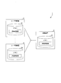
- FIG. 2 is a diagram showing a connection configuration example of the NW side device 2 and the user side device 3.
- Each of the memory 21 of the NW side device 2 and the memory 31 of the user side device 3 stores a common evaluation image for evaluating the PSNR.
- FIG. 3 is a block diagram showing the configuration of the NW side device 2.
- the NW side device 2 includes a memory 21, a transmission function unit 22, a PSNR calculation unit 23, a transmission function changing unit 24, and an upper layer function unit 25.
- the memory 21 is an example of a storage unit, and stores the evaluation image.
- the transmission function unit 22 performs a transmission function process on the data received from the user side device 3.
- the transmission function unit 22 has a frame synchronization unit 221, an error correction unit 222, and a line coding unit 223.
- the frame synchronization unit 221 performs frame synchronization on the received data.
- the error correction unit 222 performs error correction processing on the received data.
- the line coding unit 223 performs line coding on the received data.
- the PSNR calculation unit 23 calculates the evaluation image (original image) stored in the memory 21 and the image data (original image) in which the transmission function unit 22 performs the transmission function processing on the evaluation image transmitted from the user side device 3. And an image in which noise is added to the image of 1), the PSNR is calculated by Expressions (1) and (2).
- the transmission function changing unit 24 changes the transmission function executed by the transmission function unit 22 based on the PSNR calculated by the PSNR calculation unit 23.
- the upper layer functional unit 25 executes the function of the upper layer.
- the functions of the upper layer include a function of executing an edge application.
- FIG. 4 is a sequence diagram in the edge computing system 1.
- the NW side device 2 minimizes the transmission function.
- the user-side device 3 transmits a signal in which an evaluation image is set to the NW-side device 2 (step S101).
- Discovery is completed by performing communication several times using only the standard communication standard or the function with degraded performance.
- the transmission function unit 22 of the NW-side device 2 performs the transmission function process on the signal received from the user-side device 3 (step S102), and the PSNR calculation unit 23 performs the evaluation function image on which the transmission function process is performed.
- the PSNR of is calculated (step S103).
- the transmission function changing unit 24 changes the transmission function of the transmission function unit 22 based on the calculated PSNR (step S104).
- the transmission function changing unit 24 instructs the user apparatus 3 to change the transmission function in response to the change of the transmission function to the transmission function unit 22 (step S105). It should be noted that if the user side device 3 does not need to change the transmission function, the instruction can be omitted.
- the edge computing system 1 repeats the same processing as step S101 to step S105 (step S106 to step S110, step S111 to step S114).
- the NW side device 2 changes the transmission function and calculates the changed PSNR, and minimizes each transmission function (uses an algorithm with a small amount of calculation) within a range in which the PSNR satisfies the reference value T SNR. Thing).
- the transmission function changing unit 24 finishes changing the transmission function for the transmission function unit 22
- the transmission function changing unit 24 notifies the user side device 3 of the completion of the transmission function change (step S115).
- the changed transmission function may be set in the notification of the completion of the transmission function change.
- the NW side device 2 establishes communication with the user side device 3.
- the PSNR calculation unit 23 does not calculate the PSNR of the data processed by the transmission function unit 22 and outputs the data to the upper layer function unit 25.
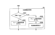
- FIG. 5 is a diagram showing a transmission function changing method for the frame synchronization function of the NW side device 2.
- the transmission function changing unit 24 reduces the frame search rate within a range in which PSNR is larger than the reference value T SNR . That is, when the transmission function changing unit 24 determines that the PSNR calculated by the PSNR calculating unit 23 is larger than the reference value T SNR (step S201: True), the value obtained by subtracting the predetermined value a from the current frame search rate R. First, the frame search rate R is reduced (step S202). The transmission function changing unit 24 outputs the updated frame search rate R to the frame synchronization unit 221. The frame synchronization unit 221 uses the updated frame search rate R to perform frame synchronization processing.
- the transmission function changing unit 24 repeats the process from step S201 every time the evaluation image is received from the user side device 3, and determines that the PSNR calculated by the PSNR calculating unit 23 is equal to or less than the reference value T SNR ( (Step S201: False), the transmission function changing unit 24 updates the frame search rate R with a value obtained by adding the predetermined value a to the current frame search rate R (step S203). This restores the value of the frame search rate R when the PSNR exceeds the reference value T SNR .
- the transmission function changing unit 24 outputs the updated frame search rate R to the frame synchronization unit 221.
- the frame synchronization unit 221 uses the updated frame search rate R to perform frame synchronization processing.
- the transmission function changing unit 24 completes the transmission function change for the frame synchronization function (step S204). That is, the transmission function changing unit 24 further notifies the user side device 3 of the transmission function change and changes another transmission function, or notifies the user side device 3 of the completion of the transmission function change.
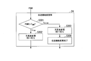
- FIG. 6 is a diagram showing a transmission function changing method for the error correction decoding method of the NW side device 2.
- the transmission function changing unit 24 reduces the redundancy within a range in which the PSNR is larger than the reference value T SNR . That is, when the transmission function changing unit 24 determines that the PSNR calculated by the PSNR calculating unit 23 is larger than the reference value T SNR (step S301: True), the transmission function changing unit 24 subtracts the predetermined value b from the current redundancy RD. , Redundancy RD is reduced (step S302). The redundancy RD indicates the number of redundancy of error correction. The transmission function changing unit 24 outputs the updated redundancy RD to the error correcting unit 222.
- the error correction unit 222 performs error correction processing using the updated redundancy RD.
- the transmission function changing unit 24 transmits a transmission function changing instruction in which the updated redundancy RD is set to the user side device 3.
- the user side device 3 changes the transmission function according to the transmission function change instruction.
- the transmission function changing unit 24 repeats the process from step S201 every time the evaluation image is received from the user side device 3, and determines that the PSNR calculated by the PSNR calculating unit 23 is equal to or less than the reference value T SNR ( (Step S301: False), the transmission function changing unit 24 updates the redundancy RD with a value obtained by adding the predetermined value b to the current redundancy RD (step S303). This restores the value of the redundancy RD when the PSNR exceeds the reference value T SNR .
- the transmission function changing unit 24 outputs the updated redundancy RD to the error correcting unit 222.
- the error correction unit 222 performs error correction processing using the updated redundancy RD.
- the transmission function changing unit 24 completes the transmission function change for the error correction decoding method (step S304). That is, the transmission function changing unit 24 further notifies the user side device 3 of the transmission function change and changes another transmission function, or notifies the user side device 3 of the completion of the transmission function change. In this notification, the redundancy RD updated in step S303 is set. The user side device 3 changes the transmission function according to the transmission function change instruction.
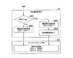
- FIG. 7 is a diagram showing a transmission function changing method for the line coding decoding method of the NW side device 2.
- the transmission function changing unit 24 uses a line coding method in which band loss is small (the number of additional bits is small) within a range in which PSNR is larger than a reference value T SNR .
- the transmission function changing unit 24 determines that the PSNR calculated by the PSNR calculating unit 23 is larger than the reference value T SNR (step S401: True)
- the value of the label Label is incremented by 1 to the current value of the label Label.
- the updated value is updated (step S402).
- the transmission function changing unit 24 outputs the updated label Label to the line coding unit 223.
- the line coding unit 223 performs demodulation by line coding according to the updated value of the label Label.
- the transmission function changing unit 24 transmits to the user side device 3 a transmission function change instruction in which the updated label value Label or information indicating the line coding method corresponding to the value is set.
- the user side device 3 changes the transmission function according to the transmission function change instruction.
- the transmission function changing unit 24 repeats the process from step S201 every time the evaluation image is received from the user side device 3, and determines that the PSNR calculated by the PSNR calculating unit 23 is equal to or less than the reference value T SNR ( (Step S401: False), the transmission function changing unit 24 updates the value of the label Label to the value obtained by subtracting 1 from the current value of the label Label (step S403).
- the transmission function changing unit 24 notifies the line coding unit 223 of the updated Label value, and restores the original line coding method when the PSNR exceeds the reference value T SNR .
- the line coding unit 223 performs demodulation by line coding according to the updated Label value.
- the transmission function changing unit 24 completes the transmission function change for the line coding decoding method (step S404). That is, the transmission function changing unit 24 further notifies the user side device 3 of the transmission function change and changes another transmission function, or notifies the user side device 3 of the completion of the transmission function change. In this notification, the value of the label Label updated in step S403 or the information indicating the line coding method corresponding to the value is set. The user side device 3 changes the transmission function according to the transmission function change instruction.
- FIG. 8 is a diagram showing an error correction method performed by the error correction unit 222.
- the header of the received frame represents control information. Therefore, the header portion of the received frame is subjected to standard error correction with high error correction capability.
- the payload portion of the received frame represents image information used in an image application or the like.
- the error correction unit 222 executes error correction for the payload portion, the function of which has been changed by the transmission function changing unit 24. The function change of the error correction method is performed by the method shown in FIG. 6 described above.
- the amount of calculation required for the transmission function of the NW side device can be reduced by performing communication with the minimum or near-minimum transmission function that satisfies the request of the edge application.
- the NW-side device of this embodiment removes noise from image data that has undergone the processing of the transmission function.
- the transmission function is minimized by using a low calculation amount image filter for noise removal. The difference from the first embodiment will be described below.
- FIG. 9 is a block diagram showing a configuration example of the NW-side device 2a of the present embodiment.
- the NW-side device 2a shown in the figure is different from the NW-side device 2 of the first embodiment shown in FIG. 3 in that an image filter unit 26 is further provided.
- the image filter unit 26 removes noise from the image information subjected to the transmission function processing in the transmission function unit 22 before the PSNR calculation in the PSNR calculation unit 23. As a result, a high PSNR can be obtained even when the performance of the transmission function is low. Further, the image filter unit 26 performs noise removal on the image information before outputting the image information received from the user side device 3 to the upper layer functional unit 25 in order to execute the edge application.
- the present embodiment it is possible to further reduce the amount of calculation required for the transmission function of the NW side device, compared to the first embodiment.
- an application process for providing a service to a user is performed in the cloud of the upper NW, not in the NW side device installed in the access station.
- the NW-side device and the cloud may cooperate to perform application processing.
- FIG. 10 is a configuration diagram of the cloud service providing system 100 according to the present embodiment.
- the NW side device 2b is connected to one or more user side devices 3.
- the NW side device 2b has the same configuration as the NW side device 2 shown in FIG. 2 or the NW side device 2a shown in FIG. 8, but the upper layer functional unit 25 does not execute the application of the service provided to the user. That is, in the access station, the NW side device 2b, which is a simple device such as a server having a minimum transmission function that satisfies the application request, is installed.
- the media data deteriorated by the transmission between the user side device 3 and the access station side device is sent from the NW side device 2b to the communication device 4 of the upper NW and is sent to the application execution device 5.
- the data output by the application executing device 5 executing the application of the service provided to the user is output to the user side device 3 via the communication device 4 and the NW side device 2b.
- applications such as image / voice processing are executed in the cloud.
- the same evaluation medium (for example, evaluation image) is held by both the user side device and the NW side device.
- the NW-side device receives the evaluation medium transmitted from the user-side device, and sets the frame so that the quality (for example, PSNR) of the received media information satisfies at least the minimum quality required by the edge computing application.
- the quality for example, PSNR
- At least one of the search rate, the redundancy of error correction, and the line coding method is changed to reduce the transmission function.
- edge computing can be realized without using a dedicated device on the NW side that complies with standards such as PON.
- the NW side device can be realized by the server. It can also be applied to the NW-side device that transfers media information to the cloud.
- a part or all of the functions of the NW side devices 2, 2a, 2b in the above-described embodiment may be realized by a computer.
- a program for realizing this function may be recorded in a computer-readable recording medium, and the program recorded in this recording medium may be read by a computer system and executed.
- the “computer system” mentioned here includes an OS and hardware such as peripheral devices.
- the "computer-readable recording medium” refers to a portable medium such as a flexible disk, a magneto-optical disk, a ROM, a CD-ROM, or a storage device such as a hard disk built in a computer system.
- the "computer-readable recording medium” means to hold a program dynamically for a short time like a communication line when transmitting the program through a network such as the Internet or a communication line such as a telephone line.
- a volatile memory inside a computer system that serves as a server or a client in that case may hold a program for a certain period of time.
- the program may be one for realizing some of the functions described above, or may be one that can realize the functions described above in combination with a program already recorded in the computer system.
- the communication system includes the network side device and the user side device.
- the communication system is the edge computing system 1 and the cloud service providing system 100.
- the network-side device includes a transmission function unit, a quality calculation unit, and a transmission function changing unit.
- the transmission function unit performs a transmission function process on the data received from the user side device.
- the quality calculation unit calculates the quality of the media data transmitted from the user side device and subjected to the transmission function processing by the transmission function unit.
- the media data is an evaluation medium such as an evaluation image
- the quality calculation unit is the PSNR calculation unit 23.
- the transmission function changing unit changes the transmission function executed by the transmission function unit so that the quality calculated by the quality calculating unit satisfies the minimum quality required by the application.
- the transmission function changing unit changes one or more of the frame search rate, the error correction redundancy, and the line coding method.
- the transmission function changing unit instructs the device on the user side to change the transmission function according to the change of the transmission function in the transmission function unit.
- the user-side device includes a transmission unit that performs a transmission function process on the media data and transmits the media data to the network-side device after the connection with the network-side device is confirmed.
- the transmission unit changes the transmission function applied to the data to be transmitted to the network side device, in accordance with the instruction from the transmission function changing unit of the network side device.
- the transmission function unit executes the processing of the transmission function on the media data received from the user side device, the quality calculation unit calculates the quality of the media data, and the transmission function change unit calculates the quality.
- the process of reducing the transmission function is repeated within a range in which the quality calculated by the unit satisfies the quality required by the application.
- the network side device notifies the user side device of the completion of the transmission function change, and establishes communication with the user side device.
- the network-side device may further include a quality improvement processing unit that performs a process of improving the quality of the data for which the transmission function process has been performed by the transmission function unit.
- the quality calculation unit calculates the quality of the media data that has undergone the processing of the transmission function by the transmission function unit and has undergone the quality improvement processing by the quality improvement processing unit.
Landscapes
- Engineering & Computer Science (AREA)
- Computer Networks & Wireless Communication (AREA)
- Signal Processing (AREA)
- Multimedia (AREA)
- Quality & Reliability (AREA)
- Detection And Prevention Of Errors In Transmission (AREA)
Abstract
通信システムは、ネットワーク側装置とユーザ側装置とを有する。ネットワーク側装置は、ユーザ側装置から受信したデータに対して、伝送機能の処理を実行する伝送機能部と、ユーザ側装置から伝送され、伝送機能部により処理が実行されたメディアデータの品質を算出する品質算出部と、算出された品質がアプリケーションにより要求される品質を満たす範囲で、伝送機能部が実行する伝送機能を変更する伝送機能変更部とを備える。
Description
本発明は、通信システム、ネットワーク側装置、伝送機能変更方法及びプログラムに関する。
近年、Internet of Things(IoT)デバイスの普及(例えば、非特許文献1参照)と共に、ネットワーク(以下、「NW」とも記載)越しに新たなサービスを提供する取り組みが多く成されている。サービスの例としては、従来はセンサー情報の集約解析のみに留まっていたが、自動運転やロボット制御のように、IoTデバイスから画像・音声などのメディア情報をNWに送信し、NW上でそれらの情報の解析を行い、IoTデバイスにフィードバックを行うようなシステムも考案されている。更に、そのようなIoTデバイスへのフィードバックを必要とするアプリケーション(以下、アプリとも記載)では、低遅延性が要求される。そのため、従来のクラウド上のサービス提供ではなく、IoTデバイスに近い距離にあるアクセス局舎等のエッジ上で、アプリケーションを動作させるエッジコンピューティングによってサービスを提供するシステムが求められている。
アクセス局舎にアプリを実行するサーバを置くことで低遅延というメリットが得られる。一方で、データセンターにアプリを実行するサーバを集約するクラウドと異なり、各地のアクセス局舎にoptical line terminal(OLT)やメディアコンバータ等の通信機器とサーバを配備するため、設備コストが大きくなることが予想される。この課題に関して、簡易なサーバのみでエッジコンピューティングを実現する方法が期待される。
通信機器では、伝送機能(フレーム同期、誤り訂正、ラインコーディング)を動作させている。これらの機能は、フレームの受信率、受信信号のエラーレートに関わってくる。
近年、伝送機能のソフトウェア実装が成されてきており(例えば、非特許文献2参照)、より演算量の大きいアルゴリズムを用いるほど、高いフレーム受信率や、低いエラーレートを得ることができる。しかし、標準の通信規格においては、高い伝送品質を保証するために、演算量の大きいアルゴリズムを使っている。
近年、伝送機能のソフトウェア実装が成されてきており(例えば、非特許文献2参照)、より演算量の大きいアルゴリズムを用いるほど、高いフレーム受信率や、低いエラーレートを得ることができる。しかし、標準の通信規格においては、高い伝送品質を保証するために、演算量の大きいアルゴリズムを使っている。
エッジコンピューティングのアプリの一例として画像処理が考えられるが、画像はノイズが入った状態でも画像処理が可能である。画像の品質評価は、peak signal noise ratio(PSNR:ピーク信号対雑音比)を用いて行われる。PSNR=30dB程度が画像圧縮でも基準となっており、画像処理に問題ないレベルの画像劣化であると考えられる。
PSNRは以下のように定義される。
PSNRは以下のように定義される。


MAXは最大のピクセル値を表す。mは縦方向の画像サイズを、nは横方向の画像サイズを示す。I(i,j)はオリジナルの画像、K(i,j)はオリジナルの画像に対してノイズが付与された画像を示す。オリジナルの画像は、ノイズが付与された画像データのPSNR評価に必須である。
一方、画像処理ではノイズを除去する方法があり、例えば、メディアンフィルタが有名な手法である。メディアンフィルタは、画像中の注目画素と周辺画素から中央値をとることでノイズを除去する方法である。画像フィルタは、画像の周辺画素の相関を利用するため、演算が単純であり、複雑な算術演算が必要な誤り訂正処理より低演算である。
総務省,"第3節 IoT化する情報通信産業",平成29年版 情報通信白書,2017年,p.125-142
Takahiro Suzuki,Sang-Yuep Kim,Jun-ichi Kani,Toshihiro Hanawa,Ken-Ichi Suzuki,Akihiro Otaka,"Demonstration of 10-Gbps Real-Time Reed-Solomon Decoding Using GPU Direct Transfer and Kernel Scheduling for Flexible Access Systems Demonstration of 10-Gbps Real-Time Reed-Solomon Decoding Using GPU Direct Transfer and Kernel Scheduling for Flexible Access Systems",Journal of Lightwave Technology,2018年5月,Vol.36, No.10,p.1875-1881
光アクセスにおけるエッジコンピューティングについて考えられる構成を図11に示す。エッジコンピューティングにおいては通信(アクセス)局舎にサーバを配備する。そのため、エッジデバイスと通信局舎間は、passive optical network(PON)の規格等での伝送が必要となり、規格を満たす専用装置が必要である。エッジコンピューティングは、その専用装置に接続されたサーバ上で行われる。従って、エッジコンピューティングのサービスを利用するユーザ毎に、各アクセス局舎に規格を満たす専用装置が必要となり設備コストの増大につながる、という問題があった。
上記事情に鑑み、本発明は、専用装置を用いずにネットワーク側の伝送機能を実現することができる通信システム、ネットワーク側装置、伝送機能変更方法及びプログラムを提供することを目的としている。
本発明の一態様は、通信システムであって、前記ネットワーク側装置は、前記ユーザ側装置から受信したデータに対して、伝送機能の処理を実行する伝送機能部と、前記ユーザ側装置から伝送され、前記伝送機能部により前記処理が実行されたメディアデータの品質を算出する品質算出部と、前記品質算出部により算出された前記品質がアプリケーションにより要求される品質を満たす範囲で、前記伝送機能部が実行する前記伝送機能を変更する伝送機能変更部とを備える、通信システムである。
本発明の一態様は、上述の通信システムであって、前記ネットワーク側装置は、前記伝送機能部が、前記ユーザ側装置から受信した前記メディアデータに対して、前記伝送機能の処理を実行し、前記品質算出部が、前記メディアデータの品質を算出し、前記伝送機能変更部が、前記品質算出部により算出された前記品質がアプリケーションにより要求される品質を満たす範囲で、前記伝送機能を低減する処理を繰り返し、前記伝送機能変更部は、前記伝送機能を低減する変更を終了した場合に前記ネットワーク側装置に伝送機能変更完了を通知する。
本発明の一態様は、上述の通信システムであって、前記ネットワーク側装置は、前記伝送機能部により前記伝送機能の処理が実行された前記データに、データの品質を改善する品質改善処理を行う品質改善処理部をさらに備え、前記品質算出部は、前記伝送機能部により前記伝送機能の処理が実行され、前記品質改善処理部により前記品質改善処理が行われたメディアデータの品質を算出する。
本発明の一態様は、上述の通信システムであって、前記伝送機能変更部は、フレーム探索率と、誤り訂正の冗長度と、ラインコーディングの方式とのうち1以上を変更する。
本発明の一態様は、上述の通信システムであって、前記伝送機能変更部は、前記ユーザ側装置から受信したフレームのヘッダーに対する誤り訂正の機能を変更せず、前記フレームのペイロード部に対する誤り訂正の機能の変更を行う。
本発明の一態様は、ユーザ側装置から受信したデータに対して、伝送機能の処理を実行する伝送機能部と、前記ユーザ側装置から伝送され、前記伝送機能部により前記処理が実行されたメディアデータの品質を算出する品質算出部と、前記品質算出部により算出された前記品質がアプリケーションにより要求される品質を満たす範囲で、前記伝送機能部が実行する前記伝送機能を変更する伝送機能変更部と、を備えるネットワーク側装置である。
本発明の一態様は、ユーザ側装置から受信したデータに対して、伝送機能の処理を実行する伝送機能実行ステップと、前記ユーザ側装置から伝送され、前記伝送機能実行ステップにおいて前記処理が実行されたメディアデータの品質を算出する品質算出ステップと、前記品質算出ステップにおいて算出された前記品質がアプリケーションにより要求される品質を満たす範囲で、前記伝送機能実行ステップにおいて実行する前記伝送機能を変更する伝送機能変更ステップと、を有する伝送機能変更方法である。
本発明の一態様は、コンピュータを、上述したネットワーク側装置として機能させるためのプログラムである。
本発明により、専用装置を用いずにネットワーク側の伝送機能を実現することが可能となる。
以下、図面を参照しながら本発明の実施形態を詳細に説明する。
本実施形態では、アプリの要求を満たす最小の又は最小に近い伝送機能による通信を行うことで通信に必要な演算量を削減する。これにより、アクセス局舎に設置するNW側装置をサーバのみで構成することを可能にする。具体的には、NW側装置は、以下により伝送機能を小さくする。
本実施形態では、アプリの要求を満たす最小の又は最小に近い伝送機能による通信を行うことで通信に必要な演算量を削減する。これにより、アクセス局舎に設置するNW側装置をサーバのみで構成することを可能にする。具体的には、NW側装置は、以下により伝送機能を小さくする。
(1)NW側装置は、画像品質の評価指標であるPSNRが基準より大きな範囲で、伝送機能(主にフレーム同期、誤り訂正、ラインコーディング等の物理層機能)を最小化する。フレーム同期では、連続的な入力信号のビット数に対して、フレームの先頭を探索する処理を行うビット数をフレーム探索率Rとしたときに、Rを小さくする。これにより、フレームの検出エラーは増えるが、演算量を削減することができる。誤り訂正に関しては、方式の冗長度を小さくすることで、演算量を削減する。ラインコーディングに関しては、低演算量の方式に変更する。なお、低演算量のラインコーディングには、複数の方式が存在する。例えば、64B66Bより8B10Bは低演算量である。
(2)NW側装置は、低演算量の画像フィルタ処理でノイズ除去を行った後に、PSNRが基準より大きな範囲で、伝送機能(フレーム同期、誤り訂正、ラインコーディング)を最小化する。
これにより、規格に準拠したNW側の専用装置を用いることなく、エッジコンピューティングを実現できる。また、低リソースで通信処理を行うことができる。
以下に、詳細な実施形態を説明する。
以下に、詳細な実施形態を説明する。
[第1の実施形態]
図1は、本実施形態によるエッジコンピューティングシステム1の構成図である。同図に示すエッジコンピューティングシステム1は、伝送機能を最小化することにより、アクセス局の局舎に設置するNW側装置2をサーバで構成し、そのサーバによりアプリケーションを動作させる。このアプリケーションは、例えば、ユーザへサービスを提供するためのエッジアプリである。NW側装置2が有する通信機能を、エッジアプリのアプリケーション要求を満たす最小の伝送機能とする。NW側装置2は、1台以上のユーザ側装置3と接続される。なお。NW側装置2は、LANによりユーザ側装置3と接続されてもよい。
図1は、本実施形態によるエッジコンピューティングシステム1の構成図である。同図に示すエッジコンピューティングシステム1は、伝送機能を最小化することにより、アクセス局の局舎に設置するNW側装置2をサーバで構成し、そのサーバによりアプリケーションを動作させる。このアプリケーションは、例えば、ユーザへサービスを提供するためのエッジアプリである。NW側装置2が有する通信機能を、エッジアプリのアプリケーション要求を満たす最小の伝送機能とする。NW側装置2は、1台以上のユーザ側装置3と接続される。なお。NW側装置2は、LANによりユーザ側装置3と接続されてもよい。
図2は、NW側装置2とユーザ側装置3の接続構成例を示す図である。PON構成のように、NW側装置2に複数のユーザ側装置3が接続される構成や、single star(SS)のようにNW側装置2とユーザ側装置3が1対1で接続される構成が想定される。NW側装置2のメモリ21及びユーザ側装置3のメモリ31のそれぞれは、PSNRを評価するための共通の評価用画像を記憶する。
図3は、NW側装置2の構成を示すブロック図である。NW側装置2は、メモリ21、伝送機能部22、PSNR算出部23、伝送機能変更部24及び上位層機能部25を有する。メモリ21は記憶部の一例であり、評価用画像を記憶する。伝送機能部22は、ユーザ側装置3から受信したデータに、伝送機能の処理を施す。伝送機能部22は、フレーム同期部221、誤り訂正部222及びラインコーディング部223を有する。フレーム同期部221は、受信したデータにフレーム同期を行う。誤り訂正部222は、受信したデータに、誤り訂正処理を行う。ラインコーディング部223は、受信したデータにラインコーディングを行う。
PSNR算出部23は、メモリ21に記憶される評価用画像(オリジナルの画像)と、ユーザ側装置3から送信された評価用画像に伝送機能部22が伝送機能の処理を施した画像データ(オリジナルの画像にノイズが付与された画像)とを用いて、式(1)及び(2)によりPSNRを算出する。伝送機能変更部24は、PSNR算出部23が算出したPSNRに基づいて伝送機能部22が実行する伝送機能の変更を行う。上位層機能部25は、上位層の機能を実行する。上位層の機能には、エッジアプリを実行する機能が含まれる。
図4は、エッジコンピューティングシステム1におけるシーケンス図である。このシーケンスによって、NW側装置2は、伝送機能を最小化する。まず、NW側装置2が、自装置と接続されたユーザ側装置3のDiscoveryを完了した後、ユーザ側装置3は、NW側装置2に評価用画像を設定した信号を送信する(ステップS101)。なお、Discoveryにおいては、標準の通信規格もしくは、性能を低下させた機能のみで通信を何度か行うことで、Discoveryを完了する。
NW側装置2の伝送機能部22は、ユーザ側装置3から受信した信号に対して伝送機能の処理を施し(ステップS102)、PSNR算出部23は、伝送機能の処理が施された評価用画像のPSNRを算出する(ステップS103)。伝送機能変更部24は、算出されたPSNRに基づいて、伝送機能部22が有する伝送機能の変更を行う(ステップS104)。伝送機能変更部24は、伝送機能部22に対する伝送機能の変更に応じて、ユーザ側装置3へ伝送機能の変更を指示する(ステップS105)。なお、ユーザ側装置3において伝送機能を変更する必要がない場合、指示を省略することができる。
エッジコンピューティングシステム1は、ステップS101~ステップS105と同様の処理を繰り返す(ステップS106~ステップS110、ステップS111~ステップS114)。この繰り返しにより、NW側装置2は伝送機能の変更と変更後のPSNR算出とを行い、PSNRが基準となる値TSNRを満たす範囲で、各伝送機能の最小化(演算量が小さいアルゴリズムを用いること)を行う。伝送機能変更部24は、伝送機能部22に対する伝送機能の変更が終了すると、伝送機能変更完了をユーザ側装置3に通知する(ステップS115)。ステップS114における伝送機能の変更によってユーザ側装置3においても伝送機能の変更が必要な場合、伝送機能変更完了の通知に、変更後の伝送機能を設定してもよい。これにより、NW側装置2は、ユーザ側装置3との間の通信を確立する。伝送機能変更完了後、PSNR算出部23は、伝送機能部22が伝送機能の処理を行ったデータにPSNRの算出を行わず、上位層機能部25に出力する。
図5は、NW側装置2のフレーム同期機能に対する伝送機能変更方法を示す図である。
一例としては、伝送機能変更部24は、PSNRが基準となる値TSNRより大きい範囲内で、フレーム探索率を小さくする。すなわち、伝送機能変更部24は、PSNR算出部23が算出したPSNRが基準値TSNRよりも大きいと判断した場合(ステップS201:True)、現在のフレーム探索率Rから所定値aを減算した値に、フレーム探索率Rを小さくする(ステップS202)。伝送機能変更部24は、更新されたフレーム探索率Rをフレーム同期部221に出力する。フレーム同期部221は、更新されたフレーム探索率Rを用いて、フレーム同期処理を行う。
一例としては、伝送機能変更部24は、PSNRが基準となる値TSNRより大きい範囲内で、フレーム探索率を小さくする。すなわち、伝送機能変更部24は、PSNR算出部23が算出したPSNRが基準値TSNRよりも大きいと判断した場合(ステップS201:True)、現在のフレーム探索率Rから所定値aを減算した値に、フレーム探索率Rを小さくする(ステップS202)。伝送機能変更部24は、更新されたフレーム探索率Rをフレーム同期部221に出力する。フレーム同期部221は、更新されたフレーム探索率Rを用いて、フレーム同期処理を行う。
そして、伝送機能変更部24は、ユーザ側装置3から評価用画像を受信するたびにステップS201からの処理を繰り返し、PSNR算出部23が算出したPSNRが基準値TSNR以下となったと判断すると(ステップS201:False)、伝送機能変更部24は、現在のフレーム探索率Rに所定値aを加算した値により、フレーム探索率Rを更新する(ステップS203)。これにより、PSNRが基準値TSNRを超えていたときのフレーム探索率Rの値に戻す。伝送機能変更部24は、更新されたフレーム探索率Rをフレーム同期部221に出力する。フレーム同期部221は、更新されたフレーム探索率Rを用いて、フレーム同期処理を行う。伝送機能変更部24は、フレーム同期機能に対する伝送機能変更を完了する(ステップS204)。すなわち、伝送機能変更部24は、ユーザ側装置3にさらに伝送機能変更の通知を行って他の伝送機能の変更を行うか、ユーザ側装置3に伝送機能変更完了の通知を行う。
図6は、NW側装置2の誤り訂正の復号方式に対する伝送機能変更方法を示す図である。一例として、伝送機能変更部24は、PSNRが基準となる値TSNRより大きい範囲内で、冗長度を小さくする。すなわち、伝送機能変更部24は、PSNR算出部23が算出したPSNRが基準値TSNRよりも大きいと判断した場合(ステップS301:True)、現在の冗長度RDから所定値bを減算した値に、冗長度RDを小さくする(ステップS302)。冗長度RDは、誤り訂正の冗長数を示す。伝送機能変更部24は、更新された冗長度RDを誤り訂正部222に出力する。誤り訂正部222は、更新された冗長度RDを用いて、誤り訂正処理を行う。また、伝送機能変更部24は、更新された冗長度RDを設定した伝送機能変更指示をユーザ側装置3へ送信する。ユーザ側装置3は、伝送機能変更指示に従って伝送機能を変更する。
そして、伝送機能変更部24は、ユーザ側装置3から評価用画像を受信するたびにステップS201からの処理を繰り返し、PSNR算出部23が算出したPSNRが基準値TSNR以下となったと判断すると(ステップS301:False)、伝送機能変更部24は、現在の冗長度RDに所定値bを加算した値により、冗長度RDを更新する(ステップS303)。これにより、PSNRが基準値TSNRを超えていたときの冗長度RDの値に元に戻す。伝送機能変更部24は、更新された冗長度RDを誤り訂正部222に出力する。誤り訂正部222は、更新された冗長度RDを用いて、誤り訂正処理を行う。伝送機能変更部24は、誤り訂正の復号方式に対する伝送機能変更を完了する(ステップS304)。すなわち、伝送機能変更部24は、ユーザ側装置3にさらに伝送機能変更の通知を行って他の伝送機能の変更を行うか、ユーザ側装置3に伝送機能変更完了の通知を行う。この通知には、ステップS303において更新された冗長度RDが設定される。ユーザ側装置3は、伝送機能変更指示に従って伝送機能を変更する。
図7は、NW側装置2のラインコーディングの復号方式に対する伝送機能変更方法を示す図である。一例として、伝送機能変更部24は、PSNRが基準となる値TSNRより大きい範囲内で、帯域のロスが少ない(追加ビットが少ない)ラインコーディング方式を使用する。本実施形態では、ラインコーディング部223は、ラベルLabel=1のときには64B66Bを行い、Label=2のときには8B10Bを行う。
伝送機能変更部24は、PSNR算出部23が算出したPSNRが基準値TSNRよりも大きいと判断した場合(ステップS401:True)、ラベルLabelの値を、現在のラベルLabelの値に1を加算した値に更新する(ステップS402)。伝送機能変更部24は、更新されたラベルLabelをラインコーディング部223に出力する。
ラインコーディング部223は、更新されたラベルLabelの値に応じたラインコーディングにより復調を行う。また、伝送機能変更部24は、更新されたラベルLabelの値、又は、その値に対応したラインコーディング方式を表す情報を設定した伝送機能変更指示をユーザ側装置3へ送信する。ユーザ側装置3は、伝送機能変更指示に従って伝送機能を変更する。
ラインコーディング部223は、更新されたラベルLabelの値に応じたラインコーディングにより復調を行う。また、伝送機能変更部24は、更新されたラベルLabelの値、又は、その値に対応したラインコーディング方式を表す情報を設定した伝送機能変更指示をユーザ側装置3へ送信する。ユーザ側装置3は、伝送機能変更指示に従って伝送機能を変更する。
そして、伝送機能変更部24は、ユーザ側装置3から評価用画像を受信するたびにステップS201からの処理を繰り返し、PSNR算出部23が算出したPSNRが基準値TSNR以下となったと判断すると(ステップS401:False)、伝送機能変更部24は、ラベルLabelの値を、現在のラベルLabelの値から1を減算した値に更新する(ステップS403)。伝送機能変更部24は、更新されたLabelの値をラインコーディング部223に通知し、PSNRが基準値TSNRを超えていたときのラインコーディング方式に元に戻す。ラインコーディング部223は、更新されたLabelの値に応じたラインコーディングにより復調を行う。伝送機能変更部24は、ラインコーディングの復号方式に対する伝送機能変更を完了する(ステップS404)。すなわち、伝送機能変更部24は、ユーザ側装置3にさらに伝送機能変更の通知を行って他の伝送機能の変更を行うか、ユーザ側装置3に伝送機能変更完了の通知を行う。この通知には、ステップS403において更新されたラベルLabelの値、又は、その値に対応したラインコーディング方式を表す情報が設定される。ユーザ側装置3は、伝送機能変更指示に従って伝送機能を変更する。
図8は、誤り訂正部222が行う誤り訂正の方法を示す図である。受信フレームのヘッダーは、制御情報を表す。そこで、受信フレームのヘッダーの部分は、高い誤り訂正能力のある標準の誤り訂正を行う。受信フレームのペイロード部分は、画像アプリケーションなどにおいて用いられる画像情報を表す。誤り訂正部222は、このペイロード部分に関しては、伝送機能変更部24により機能変更された誤り訂正を実行する。誤り訂正方式の機能変更は、上述した図6に示す方法で行われる。
本実施形態によれば、エッジアプリの要求を満たす最小の又は最小に近い伝送機能による通信を行うことで、NW側装置の伝送機能に必要な演算量を削減できる。
[第2の実施形態]
本実施形態のNW側装置は、伝送機能の処理が施された画像データに対してノイズ除去を行う。ノイズ除去として低演算量の画像フィルタを用いることで、伝送機能を最小化する。以下では、第1の実施形態との差分を説明する。
本実施形態のNW側装置は、伝送機能の処理が施された画像データに対してノイズ除去を行う。ノイズ除去として低演算量の画像フィルタを用いることで、伝送機能を最小化する。以下では、第1の実施形態との差分を説明する。
図9は、本実施形態のNW側装置2aの構成例を示すブロック図である。同図に示すNW側装置2aが、図3に示す第1の実施形態のNW側装置2と異なる点は、画像フィルタ部26をさらに備える点である。画像フィルタ部26は、PSNR算出部23におけるPSNR算出前に、伝送機能部22において伝送機能の処理が施された画像情報のノイズ除去を行う。これにより、伝送機能の性能が低い場合でも、高いPSNRを得ることが出来る。また、画像フィルタ部26は、エッジアプリ実行のために、ユーザ側装置3から受信した画像情報を上位層機能部25へ出力する前に、画像情報のノイズ除去を行う。
本実施形態によれば、第1の実施形態よりもさらに、NW側装置の伝送機能に必要な演算量を削減できる。
[第3の実施形態]
本実施形態では、アクセス局舎に設置されるNW側装置ではなく、上位NWにおけるクラウドにおいてユーザへサービスを提供するアプリ処理を行う。あるいは、NW側装置とクラウドが協働してアプリ処理を行ってもよい。
本実施形態では、アクセス局舎に設置されるNW側装置ではなく、上位NWにおけるクラウドにおいてユーザへサービスを提供するアプリ処理を行う。あるいは、NW側装置とクラウドが協働してアプリ処理を行ってもよい。
図10は、本実施形態によるクラウドサービス提供システム100の構成図である。NW側装置2bは、1台以上のユーザ側装置3と接続される。NW側装置2bは、図2に示すNW側装置2又は図8に示すNW側装置2aと同様の構成であるが、上位層機能部25は、ユーザへ提供するサービスのアプリケーションを実行しない。すなわち、アクセス局舎には、アプリケーション要求を満たす最小の伝送機能を有するサーバなどの簡易な装置であるNW側装置2bを設置する。ユーザ側装置3とアクセス局舎側装置との間の伝送で劣化したメディアデータは、NW側装置2bから上位NWの通信装置4まで送られ、アプリ実行装置5に送信される。また、アプリ実行装置5が、ユーザへ提供するサービスのアプリケーションを実行することにより出力されたデータは、通信装置4及びNW側装置2bを介してユーザ側装置3へ出力される。これにより、クラウドで画像・音声処理等のアプリケーションを実行する。
本実施形態によれば、クラウドでアプリを実行する場合でも、アクセス局舎のNW側装置の伝送機能に必要な演算量を削減できる。
上述した実施形態によれば、ユーザ側装置とNW側装置の双方で同一の評価用メディア(例えば、評価用画像)を保持する。NW側装置は、ユーザ側装置から送信された評価用メディアを受信し、受信したメディア情報の品質(例えば、PSNR)がエッジコンピューティングのアプリが要求する最低限の品質を少なくとも満たすように、フレーム探索率、誤り訂正の冗長度、ラインコーディング方式のうち少なくとも1つを変更し、伝送機能を低減する。これにより、PON等の規格に準拠したNW側の専用装置を用いることなく、エッジコンピューティングを実現することができる。アプリの要求を満たす最小の伝送機能で通信を行って、NW側装置において必要な演算量を削減することができるため、NW側装置をサーバにより実現することが可能となる。また、クラウドへメディア情報を転送するNW側装置にも適用可能である。
上述した実施形態におけるNW側装置2、2a、2bの一部又は全ての機能をコンピュータで実現するようにしてもよい。その場合、この機能を実現するためのプログラムをコンピュータ読み取り可能な記録媒体に記録して、この記録媒体に記録されたプログラムをコンピュータシステムに読み込ませ、実行することによって実現してもよい。なお、ここでいう「コンピュータシステム」とは、OSや周辺機器等のハードウェアを含むものとする。また、「コンピュータ読み取り可能な記録媒体」とは、フレキシブルディスク、光磁気ディスク、ROM、CD-ROM等の可搬媒体、コンピュータシステムに内蔵されるハードディスク等の記憶装置のことをいう。さらに「コンピュータ読み取り可能な記録媒体」とは、インターネット等のネットワークや電話回線等の通信回線を介してプログラムを送信する場合の通信線のように、短時間の間、動的にプログラムを保持するもの、その場合のサーバやクライアントとなるコンピュータシステム内部の揮発性メモリのように、一定時間プログラムを保持しているものも含んでもよい。また上記プログラムは、前述した機能の一部を実現するためのものであってもよく、さらに前述した機能をコンピュータシステムにすでに記録されているプログラムとの組み合わせで実現できるものであってもよい。
以上説明した実施形態によれば、通信システムは、ネットワーク側装置と、ユーザ側装置とを有する。例えば、通信システムは、エッジコンピューティングシステム1、クラウドサービス提供システム100である。ネットワーク側装置は、伝送機能部と、品質算出部と、伝送機能変更部とを備える。伝送機能部は、ユーザ側装置から受信したデータに対して、伝送機能の処理を実行する。品質算出部は、ユーザ側装置から伝送され、伝送機能部により伝送機能の処理が実行されたメディアデータの品質を算出する。例えば、メディアデータは、評価用画像などの評価用メディアであり、品質算出部は、PSNR算出部23である。伝送機能変更部は、品質算出部により算出された品質がアプリケーションにより要求される最低限の品質を満たすように、伝送機能部が実行する伝送機能を変更する。
例えば、伝送機能変更部は、フレーム探索率と、誤り訂正の冗長度と、ラインコーディングの方式とのうち1以上を変更する。
例えば、伝送機能変更部は、フレーム探索率と、誤り訂正の冗長度と、ラインコーディングの方式とのうち1以上を変更する。
また、伝送機能変更部は、伝送機能部における伝送機能の変更に応じて、ユーザ側の装置に伝送機能の変更を指示する。一方で、ユーザ側装置は、ネットワーク側装置との接続が確認された後に、メディアデータに伝送機能の処理を施してネットワーク側装置へ送信する送信部を備える。送信部は、ネットワーク側装置の伝送機能変更部からの指示に従って、ネットワーク側装置に送信するデータに施す伝送機能を変更する。
ネットワーク側装置は、伝送機能部が、ユーザ側装置から受信したメディアデータに対して伝送機能の処理を実行し、品質算出部が、メディアデータの品質を算出し、伝送機能変更部が、品質算出部により算出された品質がアプリケーションにより要求される品質を満たす範囲で、伝送機能を低減する処理を繰り返す。伝送機能変更部が、この繰り返しによって伝送機能を低減する変更を終了した場合に、ネットワーク側装置は、ユーザ側装置に伝送機能変更完了を通知し、ユーザ側装置との通信を確立する。
ネットワーク側装置は、伝送機能部により伝送機能の処理が実行されたデータに、データの品質を改善する処理を行う品質改善処理部をさらに備えてもよい。品質算出部は、伝送機能部により伝送機能の処理が実行され、品質改善処理部により品質改善処理が行われたメディアデータの品質を算出する。
以上、この発明の実施形態について図面を参照して詳述してきたが、具体的な構成はこの実施形態に限られるものではなく、この発明の要旨を逸脱しない範囲の設計等も含まれる。
アクセスシステムに適用可能である。
1…エッジコンピューティングシステム, 2、2a、2b…NW側装置, 3…ユーザ側装置, 4…通信装置, 5…アプリ実行装置, 21…メモリ, 22…伝送機能部, 23…PSNR算出部, 24…伝送機能変更部, 25…上位層機能部, 221…フレーム同期部, 222…誤り訂正部, 223…ラインコーディング部, 26…画像フィルタ部, 31…メモリ, 100…クラウドサービス提供システム
Claims (8)
- ネットワーク側装置とユーザ側装置とを有する通信システムであって、
前記ネットワーク側装置は、
前記ユーザ側装置から受信したデータに対して、伝送機能の処理を実行する伝送機能部と、
前記ユーザ側装置から伝送され、前記伝送機能部により前記処理が実行されたメディアデータの品質を算出する品質算出部と、
前記品質算出部により算出された前記品質がアプリケーションにより要求される品質を満たす範囲で、前記伝送機能部が実行する前記伝送機能を変更する伝送機能変更部とを備える、
通信システム。 - 前記ネットワーク側装置は、前記伝送機能部が、前記ユーザ側装置から受信した前記メディアデータに対して、前記伝送機能の処理を実行し、前記品質算出部が、前記メディアデータの品質を算出し、前記伝送機能変更部が、前記品質算出部により算出された前記品質がアプリケーションにより要求される品質を満たす範囲で、前記伝送機能を低減する処理を繰り返し、
前記伝送機能変更部は、前記伝送機能を低減する変更を終了した場合に前記ネットワーク側装置に伝送機能変更完了を通知する、
請求項1に記載の通信システム。 - 前記ネットワーク側装置は、前記伝送機能部により前記伝送機能の処理が実行された前記データに、データの品質を改善する品質改善処理を行う品質改善処理部をさらに備え、
前記品質算出部は、前記伝送機能部により前記伝送機能の処理が実行され、前記品質改善処理部により前記品質改善処理が行われたメディアデータの品質を算出する、
請求項1又は請求項2に記載の通信システム。 - 前記伝送機能変更部は、フレーム探索率と、誤り訂正の冗長度と、ラインコーディングの方式とのうち1以上を変更する、
請求項1から請求項3のいずれか一項に記載の通信システム。 - 前記伝送機能変更部は、前記ユーザ側装置から受信したフレームのヘッダーに対する誤り訂正の機能を変更せず、前記フレームのペイロード部に対する誤り訂正の機能の変更を行う、
請求項4に記載の通信システム。 - ユーザ側装置から受信したデータに対して、伝送機能の処理を実行する伝送機能部と、
前記ユーザ側装置から伝送され、前記伝送機能部により前記処理が実行されたメディアデータの品質を算出する品質算出部と、
前記品質算出部により算出された前記品質がアプリケーションにより要求される品質を満たす範囲で、前記伝送機能部が実行する前記伝送機能を変更する伝送機能変更部と、
を備えるネットワーク側装置。 - ユーザ側装置から受信したデータに対して、伝送機能の処理を実行する伝送機能実行ステップと、
前記ユーザ側装置から伝送され、前記伝送機能実行ステップにおいて前記処理が実行されたメディアデータの品質を算出する品質算出ステップと、
前記品質算出ステップにおいて算出された前記品質がアプリケーションにより要求される品質を満たす範囲で、前記伝送機能実行ステップにおいて実行する前記伝送機能を変更する伝送機能変更ステップと、
を有する伝送機能変更方法。 - コンピュータを、
請求項6に記載のネットワーク側装置として機能させるためのプログラム。
Priority Applications (1)
| Application Number | Priority Date | Filing Date | Title |
|---|---|---|---|
| US17/286,973 US11558447B2 (en) | 2018-10-25 | 2019-10-03 | Communication system, network-side apparatus, transmission function changing method and program |
Applications Claiming Priority (2)
| Application Number | Priority Date | Filing Date | Title |
|---|---|---|---|
| JP2018201211A JP7161103B2 (ja) | 2018-10-25 | 2018-10-25 | 通信システム、ネットワーク側装置、伝送機能変更方法及びプログラム |
| JP2018-201211 | 2018-10-25 |
Publications (1)
| Publication Number | Publication Date |
|---|---|
| WO2020085029A1 true WO2020085029A1 (ja) | 2020-04-30 |
Family
ID=70330959
Family Applications (1)
| Application Number | Title | Priority Date | Filing Date |
|---|---|---|---|
| PCT/JP2019/039076 Ceased WO2020085029A1 (ja) | 2018-10-25 | 2019-10-03 | 通信システム、ネットワーク側装置、伝送機能変更方法及びプログラム |
Country Status (3)
| Country | Link |
|---|---|
| US (1) | US11558447B2 (ja) |
| JP (1) | JP7161103B2 (ja) |
| WO (1) | WO2020085029A1 (ja) |
Citations (4)
| Publication number | Priority date | Publication date | Assignee | Title |
|---|---|---|---|---|
| JP2007104571A (ja) * | 2005-10-07 | 2007-04-19 | Sumitomo Electric Ind Ltd | 光通信システムにおける制御局側装置及び端末局側装置 |
| JP2009296164A (ja) * | 2008-06-03 | 2009-12-17 | Canon Inc | データ送信装置、その制御方法及びプログラム |
| US20100296428A1 (en) * | 2007-09-28 | 2010-11-25 | Pin-Han Ho | A robust system and method for wireless data multicasting using superposition modulation |
| JP2012529847A (ja) * | 2009-06-10 | 2012-11-22 | アルカテル−ルーセント | チャネル適応型エラー耐性バーストモード伝送のためのシステムおよび方法 |
Family Cites Families (13)
| Publication number | Priority date | Publication date | Assignee | Title |
|---|---|---|---|---|
| US7457359B2 (en) * | 2001-09-26 | 2008-11-25 | Mabey Danny L | Systems, devices and methods for securely distributing highly-compressed multimedia content |
| US7693058B2 (en) * | 2002-12-03 | 2010-04-06 | Hewlett-Packard Development Company, L.P. | Method for enhancing transmission quality of streaming media |
| DE602004030487D1 (de) * | 2004-01-30 | 2011-01-20 | Ericsson Telefon Ab L M | Paketablaufsteuerung zur Datenstromübertragung |
| US8914529B2 (en) * | 2007-01-22 | 2014-12-16 | Microsoft Corporation | Dynamically adapting media content streaming and playback parameters for existing streaming and playback conditions |
| US20090300687A1 (en) * | 2008-05-28 | 2009-12-03 | Broadcom Corporation | Edge device establishing and adjusting wireless link parameters in accordance with qos-desired video data rate |
| WO2012029648A1 (ja) * | 2010-08-30 | 2012-03-08 | 日本電気株式会社 | サーバ装置、映像品質計測システム、映像品質計測方法およびプログラム |
| US10389780B2 (en) * | 2012-02-08 | 2019-08-20 | Arris Enterprises Llc | Managed adaptive streaming |
| US9264475B2 (en) * | 2012-12-31 | 2016-02-16 | Sonic Ip, Inc. | Use of objective quality measures of streamed content to reduce streaming bandwidth |
| US9386308B2 (en) * | 2013-07-16 | 2016-07-05 | Cisco Technology, Inc. | Quality optimization with buffer and horizon constraints in adaptive streaming |
| KR102158733B1 (ko) * | 2013-10-16 | 2020-09-22 | 삼성전자 주식회사 | 자원 제어 장치 및 방법 |
| US9894130B2 (en) * | 2014-09-23 | 2018-02-13 | Intel Corporation | Video quality enhancement |
| CA3030827C (en) * | 2016-07-14 | 2021-08-24 | Arris Enterprises Llc | Quality tagging in adaptive bitrate technologies |
| US11019349B2 (en) * | 2017-01-20 | 2021-05-25 | Snap Inc. | Content-based client side video transcoding |
-
2018
- 2018-10-25 JP JP2018201211A patent/JP7161103B2/ja active Active
-
2019
- 2019-10-03 WO PCT/JP2019/039076 patent/WO2020085029A1/ja not_active Ceased
- 2019-10-03 US US17/286,973 patent/US11558447B2/en active Active
Patent Citations (4)
| Publication number | Priority date | Publication date | Assignee | Title |
|---|---|---|---|---|
| JP2007104571A (ja) * | 2005-10-07 | 2007-04-19 | Sumitomo Electric Ind Ltd | 光通信システムにおける制御局側装置及び端末局側装置 |
| US20100296428A1 (en) * | 2007-09-28 | 2010-11-25 | Pin-Han Ho | A robust system and method for wireless data multicasting using superposition modulation |
| JP2009296164A (ja) * | 2008-06-03 | 2009-12-17 | Canon Inc | データ送信装置、その制御方法及びプログラム |
| JP2012529847A (ja) * | 2009-06-10 | 2012-11-22 | アルカテル−ルーセント | チャネル適応型エラー耐性バーストモード伝送のためのシステムおよび方法 |
Non-Patent Citations (2)
| Title |
|---|
| SAKAUSHI, AIRI ET AL.: "Image Enhancement and Rate Adaptation for High-quality and Network-friendly Video Surveillance System", IEICE TECHNICAL REPORT, vol. 117, no. 330, 2017, pages 123 - 128 * |
| SUZUKI, TAKAHIRO ET AL.: "Software Implementation of PON Physical-Layer Processing for Fully Software-Defined Optical Access Systems", 2018 EUROPEAN CONFERENCE ON OPTICAL COMMUNICATION (ECOC, September 2018 (2018-09-01), pages 1 - 3, XP033447413 * |
Also Published As
| Publication number | Publication date |
|---|---|
| JP2020068488A (ja) | 2020-04-30 |
| JP7161103B2 (ja) | 2022-10-26 |
| US11558447B2 (en) | 2023-01-17 |
| US20210392181A1 (en) | 2021-12-16 |
Similar Documents
| Publication | Publication Date | Title |
|---|---|---|
| KR101640508B1 (ko) | 무선 시스템에서의 비압축 영상 통신을 위한 점진적 레이트 조정 방법 및 시스템 | |
| JP2010521856A (ja) | 通信システムにおけるデータ伝送方法 | |
| CN103188054B (zh) | 反馈时延的获取方法、装置及系统 | |
| CN109992419A (zh) | 一种优化的协同边缘计算低延迟任务分配卸载方法 | |
| US20150296406A1 (en) | Traffic distribution method, device, and system | |
| CN113068001B (zh) | 基于级联摄像机的数据处理方法、装置、设备和介质 | |
| CN118489248A (zh) | 用于视频压缩的基于时间注意力的神经网络 | |
| JP2002111684A (ja) | 無線通信システムおよびそのタイムアウト値更新方法 | |
| KR20230165340A (ko) | 코딩 툴과 연관된 전체 제약 플래그의 사용 | |
| US11910042B2 (en) | Dynamic allocation of compute capacity in video stream processing | |
| JP6512282B2 (ja) | 通信装置、利用可能帯域計算システム、利用可能帯域計算方法及びプログラム | |
| US20160073173A1 (en) | Video stream providing method and system and relay apparatus | |
| JP7161103B2 (ja) | 通信システム、ネットワーク側装置、伝送機能変更方法及びプログラム | |
| US11334979B2 (en) | System and method to detect macroblocking in images | |
| JP2020145584A (ja) | 送信装置、受信装置、及びプログラム | |
| CN115623155A (zh) | 视频数据处理方法、视频数据处理装置、存储介质 | |
| CN106162227B (zh) | 实时视频传输的rs编码冗余包分配方法和发送设备 | |
| CN105681730A (zh) | 一种进行医疗软视频会议的方法 | |
| CN108111878B (zh) | 一种媒体流图像传输的方法及系统 | |
| JP7533752B2 (ja) | 情報通信装置、情報通信方法及び情報通信プログラム | |
| US11601650B2 (en) | Dynamic allocation of virtual and/or physical resources vis-a-vis virtual machines in video stream processing | |
| US20180007390A1 (en) | Smart small form-factor pluggable (sfp) transceiver | |
| Farzamnia et al. | Multicasting multiple description coding using p-cycle network coding. | |
| Pankov et al. | Holographic traffic network characteristics: Prototype implementation | |
| CN119520714A (zh) | 视频通话数据的ai视频超分辨率处理的控制方法及装置 |
Legal Events
| Date | Code | Title | Description |
|---|---|---|---|
| 121 | Ep: the epo has been informed by wipo that ep was designated in this application |
Ref document number: 19876874 Country of ref document: EP Kind code of ref document: A1 |
|
| NENP | Non-entry into the national phase |
Ref country code: DE |
|
| 122 | Ep: pct application non-entry in european phase |
Ref document number: 19876874 Country of ref document: EP Kind code of ref document: A1 |