WO2020084919A1 - Light-emitting element - Google Patents
Light-emitting element Download PDFInfo
- Publication number
- WO2020084919A1 WO2020084919A1 PCT/JP2019/034947 JP2019034947W WO2020084919A1 WO 2020084919 A1 WO2020084919 A1 WO 2020084919A1 JP 2019034947 W JP2019034947 W JP 2019034947W WO 2020084919 A1 WO2020084919 A1 WO 2020084919A1
- Authority
- WO
- WIPO (PCT)
- Prior art keywords
- ring
- group
- atom
- layer
- substituents
- Prior art date
Links
- 150000004696 coordination complex Chemical class 0.000 claims abstract description 177
- 150000001875 compounds Chemical class 0.000 claims abstract description 132
- 125000001424 substituent group Chemical group 0.000 claims description 235
- 239000000463 material Substances 0.000 claims description 155
- 125000000623 heterocyclic group Chemical group 0.000 claims description 134
- 238000002347 injection Methods 0.000 claims description 93
- 239000007924 injection Substances 0.000 claims description 93
- 125000004432 carbon atom Chemical group C* 0.000 claims description 75
- JUJWROOIHBZHMG-UHFFFAOYSA-N Pyridine Chemical group C1=CC=NC=C1 JUJWROOIHBZHMG-UHFFFAOYSA-N 0.000 claims description 63
- 125000003118 aryl group Chemical group 0.000 claims description 55
- 125000004435 hydrogen atom Chemical group [H]* 0.000 claims description 53
- 125000004429 atom Chemical group 0.000 claims description 52
- PBMFSQRYOILNGV-UHFFFAOYSA-N pyridazine Chemical group C1=CC=NN=C1 PBMFSQRYOILNGV-UHFFFAOYSA-N 0.000 claims description 42
- 125000003277 amino group Chemical group 0.000 claims description 41
- 230000005525 hole transport Effects 0.000 claims description 38
- 229910052799 carbon Inorganic materials 0.000 claims description 32
- 125000000217 alkyl group Chemical group 0.000 claims description 30
- 125000001997 phenyl group Chemical group [H]C1=C([H])C([H])=C(*)C([H])=C1[H] 0.000 claims description 30
- 125000000753 cycloalkyl group Chemical group 0.000 claims description 25
- 125000002950 monocyclic group Chemical group 0.000 claims description 24
- 125000004433 nitrogen atom Chemical group N* 0.000 claims description 24
- 238000000295 emission spectrum Methods 0.000 claims description 23
- 229910052757 nitrogen Inorganic materials 0.000 claims description 22
- 239000003446 ligand Substances 0.000 claims description 19
- WCZVZNOTHYJIEI-UHFFFAOYSA-N cinnoline Chemical group N1=NC=CC2=CC=CC=C21 WCZVZNOTHYJIEI-UHFFFAOYSA-N 0.000 claims description 18
- BASFCYQUMIYNBI-UHFFFAOYSA-N platinum Chemical group [Pt] BASFCYQUMIYNBI-UHFFFAOYSA-N 0.000 claims description 18
- 229910052741 iridium Inorganic materials 0.000 claims description 17
- GKOZUEZYRPOHIO-UHFFFAOYSA-N iridium atom Chemical group [Ir] GKOZUEZYRPOHIO-UHFFFAOYSA-N 0.000 claims description 17
- 125000002029 aromatic hydrocarbon group Chemical group 0.000 claims description 16
- 239000003963 antioxidant agent Substances 0.000 claims description 15
- 125000000732 arylene group Chemical group 0.000 claims description 15
- KDLHZDBZIXYQEI-UHFFFAOYSA-N Palladium Chemical group [Pd] KDLHZDBZIXYQEI-UHFFFAOYSA-N 0.000 claims description 14
- 230000003078 antioxidant effect Effects 0.000 claims description 14
- 125000003545 alkoxy group Chemical group 0.000 claims description 13
- 125000004430 oxygen atom Chemical group O* 0.000 claims description 12
- 229910052703 rhodium Inorganic materials 0.000 claims description 12
- MHOVAHRLVXNVSD-UHFFFAOYSA-N rhodium atom Chemical group [Rh] MHOVAHRLVXNVSD-UHFFFAOYSA-N 0.000 claims description 12
- 125000000129 anionic group Chemical group 0.000 claims description 11
- 125000000000 cycloalkoxy group Chemical group 0.000 claims description 11
- WTKZEGDFNFYCGP-UHFFFAOYSA-N Pyrazole Chemical group C=1C=NNC=1 WTKZEGDFNFYCGP-UHFFFAOYSA-N 0.000 claims description 9
- 125000002911 monocyclic heterocycle group Chemical group 0.000 claims description 8
- 229910052717 sulfur Inorganic materials 0.000 claims description 8
- 125000004434 sulfur atom Chemical group 0.000 claims description 8
- 125000004104 aryloxy group Chemical group 0.000 claims description 7
- 125000002947 alkylene group Chemical group 0.000 claims description 6
- 125000002993 cycloalkylene group Chemical group 0.000 claims description 6
- 125000005843 halogen group Chemical group 0.000 claims description 6
- 125000004093 cyano group Chemical group *C#N 0.000 claims description 4
- 238000004020 luminiscence type Methods 0.000 claims description 2
- 238000006467 substitution reaction Methods 0.000 claims description 2
- 125000001425 triazolyl group Chemical group 0.000 claims 1
- 229910052751 metal Inorganic materials 0.000 abstract description 27
- 239000002184 metal Substances 0.000 abstract description 27
- 239000010410 layer Substances 0.000 description 378
- 238000000034 method Methods 0.000 description 56
- 239000000203 mixture Substances 0.000 description 48
- -1 2- Ethylhexyl group Chemical group 0.000 description 45
- 150000004945 aromatic hydrocarbons Chemical group 0.000 description 37
- 230000015572 biosynthetic process Effects 0.000 description 36
- TXCDCPKCNAJMEE-UHFFFAOYSA-N dibenzofuran Chemical compound C1=CC=C2C3=CC=CC=C3OC2=C1 TXCDCPKCNAJMEE-UHFFFAOYSA-N 0.000 description 34
- UHOVQNZJYSORNB-UHFFFAOYSA-N Benzene Chemical compound C1=CC=CC=C1 UHOVQNZJYSORNB-UHFFFAOYSA-N 0.000 description 33
- 125000005842 heteroatom Chemical group 0.000 description 33
- IYYZUPMFVPLQIF-UHFFFAOYSA-N dibenzothiophene Chemical compound C1=CC=C2C3=CC=CC=C3SC2=C1 IYYZUPMFVPLQIF-UHFFFAOYSA-N 0.000 description 30
- 239000000976 ink Substances 0.000 description 30
- 229920000642 polymer Polymers 0.000 description 30
- 150000001721 carbon Chemical group 0.000 description 27
- UJOBWOGCFQCDNV-UHFFFAOYSA-N 9H-carbazole Chemical compound C1=CC=C2C3=CC=CC=C3NC2=C1 UJOBWOGCFQCDNV-UHFFFAOYSA-N 0.000 description 26
- 239000002904 solvent Substances 0.000 description 24
- WYURNTSHIVDZCO-UHFFFAOYSA-N Tetrahydrofuran Chemical compound C1CCOC1 WYURNTSHIVDZCO-UHFFFAOYSA-N 0.000 description 16
- 239000000758 substrate Substances 0.000 description 16
- JYEUMXHLPRZUAT-UHFFFAOYSA-N 1,2,3-triazine Chemical compound C1=CN=NN=C1 JYEUMXHLPRZUAT-UHFFFAOYSA-N 0.000 description 15
- YXFVVABEGXRONW-UHFFFAOYSA-N Toluene Chemical compound CC1=CC=CC=C1 YXFVVABEGXRONW-UHFFFAOYSA-N 0.000 description 15
- 150000002391 heterocyclic compounds Chemical class 0.000 description 15
- UFWIBTONFRDIAS-UHFFFAOYSA-N Naphthalene Chemical compound C1=CC=CC2=CC=CC=C21 UFWIBTONFRDIAS-UHFFFAOYSA-N 0.000 description 14
- 238000004519 manufacturing process Methods 0.000 description 14
- 230000000052 comparative effect Effects 0.000 description 13
- UMJSCPRVCHMLSP-UHFFFAOYSA-N pyridine Natural products COC1=CC=CN=C1 UMJSCPRVCHMLSP-UHFFFAOYSA-N 0.000 description 13
- 238000003786 synthesis reaction Methods 0.000 description 13
- YLQBMQCUIZJEEH-UHFFFAOYSA-N Furan Chemical compound C=1C=COC=1 YLQBMQCUIZJEEH-UHFFFAOYSA-N 0.000 description 12
- 150000003384 small molecules Chemical class 0.000 description 12
- 125000002619 bicyclic group Chemical group 0.000 description 11
- 238000011156 evaluation Methods 0.000 description 11
- 125000000609 carbazolyl group Chemical group C1(=CC=CC=2C3=CC=CC=C3NC12)* 0.000 description 10
- WEVYAHXRMPXWCK-UHFFFAOYSA-N Acetonitrile Chemical compound CC#N WEVYAHXRMPXWCK-UHFFFAOYSA-N 0.000 description 9
- RMBPEFMHABBEKP-UHFFFAOYSA-N fluorene Chemical compound C1=CC=C2C3=C[CH]C=CC3=CC2=C1 RMBPEFMHABBEKP-UHFFFAOYSA-N 0.000 description 9
- NIHNNTQXNPWCJQ-UHFFFAOYSA-N o-biphenylenemethane Natural products C1=CC=C2CC3=CC=CC=C3C2=C1 NIHNNTQXNPWCJQ-UHFFFAOYSA-N 0.000 description 9
- BPMFPOGUJAAYHL-UHFFFAOYSA-N 9H-Pyrido[2,3-b]indole Chemical compound C1=CC=C2C3=CC=CC=C3NC2=N1 BPMFPOGUJAAYHL-UHFFFAOYSA-N 0.000 description 8
- BZHCVCNZIJZMRN-UHFFFAOYSA-N 9h-pyridazino[3,4-b]indole Chemical compound N1=CC=C2C3=CC=CC=C3NC2=N1 BZHCVCNZIJZMRN-UHFFFAOYSA-N 0.000 description 8
- YNPNZTXNASCQKK-UHFFFAOYSA-N phenanthrene Chemical compound C1=CC=C2C3=CC=CC=C3C=CC2=C1 YNPNZTXNASCQKK-UHFFFAOYSA-N 0.000 description 8
- 239000000243 solution Substances 0.000 description 7
- CTQNGGLPUBDAKN-UHFFFAOYSA-N O-Xylene Chemical compound CC1=CC=CC=C1C CTQNGGLPUBDAKN-UHFFFAOYSA-N 0.000 description 6
- 125000003342 alkenyl group Chemical group 0.000 description 6
- MWPLVEDNUUSJAV-UHFFFAOYSA-N anthracene Chemical compound C1=CC=CC2=CC3=CC=CC=C3C=C21 MWPLVEDNUUSJAV-UHFFFAOYSA-N 0.000 description 6
- 125000003983 fluorenyl group Chemical group C1(=CC=CC=2C3=CC=CC=C3CC12)* 0.000 description 6
- PUZPDOWCWNUUKD-UHFFFAOYSA-M sodium fluoride Chemical compound [F-].[Na+] PUZPDOWCWNUUKD-UHFFFAOYSA-M 0.000 description 6
- 150000003852 triazoles Chemical group 0.000 description 6
- 239000008096 xylene Substances 0.000 description 6
- TZMSYXZUNZXBOL-UHFFFAOYSA-N 10H-phenoxazine Chemical compound C1=CC=C2NC3=CC=CC=C3OC2=C1 TZMSYXZUNZXBOL-UHFFFAOYSA-N 0.000 description 5
- 125000000304 alkynyl group Chemical group 0.000 description 5
- 125000006615 aromatic heterocyclic group Chemical group 0.000 description 5
- 239000000470 constituent Substances 0.000 description 5
- XXPBFNVKTVJZKF-UHFFFAOYSA-N dihydrophenanthrene Natural products C1=CC=C2CCC3=CC=CC=C3C2=C1 XXPBFNVKTVJZKF-UHFFFAOYSA-N 0.000 description 5
- 229910052731 fluorine Inorganic materials 0.000 description 5
- 238000004128 high performance liquid chromatography Methods 0.000 description 5
- 150000002500 ions Chemical class 0.000 description 5
- 125000002183 isoquinolinyl group Chemical group C1(=NC=CC2=CC=CC=C12)* 0.000 description 5
- 150000002605 large molecules Chemical class 0.000 description 5
- 238000004528 spin coating Methods 0.000 description 5
- AFBZMKWCZFFWIC-HVEFNXCZSA-N (3s)-3-[[(2s)-2-[[(2s)-2-[[(2r)-2-[[(2s)-2-[[(2s)-2-[[(2s)-2-amino-3-methylbutanoyl]amino]-3-(4-hydroxyphenyl)propanoyl]amino]-3-(4-hydroxyphenyl)propanoyl]amino]-3-sulfanylpropanoyl]amino]-3-(1h-imidazol-5-yl)propanoyl]amino]-4-methylpentanoyl]amino]-4-[ Chemical compound C([C@@H](C(=O)N[C@@H](CC(C)C)C(=O)N[C@@H](CC(O)=O)C(=O)N[C@@H]([C@@H](C)CC)C(=O)N[C@@H]([C@@H](C)CC)C(=O)N[C@@H](CC=1C2=CC=CC=C2NC=1)C(O)=O)NC(=O)[C@H](CS)NC(=O)[C@H](CC=1C=CC(O)=CC=1)NC(=O)[C@H](CC=1C=CC(O)=CC=1)NC(=O)[C@@H](N)C(C)C)C1=CNC=N1 AFBZMKWCZFFWIC-HVEFNXCZSA-N 0.000 description 4
- 0 *C1(C2)C2(*)c2ccccc2C2c3ccccc3C=C*12 Chemical compound *C1(C2)C2(*)c2ccccc2C2c3ccccc3C=C*12 0.000 description 4
- WJFKNYWRSNBZNX-UHFFFAOYSA-N 10H-phenothiazine Chemical compound C1=CC=C2NC3=CC=CC=C3SC2=C1 WJFKNYWRSNBZNX-UHFFFAOYSA-N 0.000 description 4
- HJCUTNIGJHJGCF-UHFFFAOYSA-N 9,10-dihydroacridine Chemical compound C1=CC=C2CC3=CC=CC=C3NC2=C1 HJCUTNIGJHJGCF-UHFFFAOYSA-N 0.000 description 4
- KAESVJOAVNADME-UHFFFAOYSA-N Pyrrole Chemical compound C=1C=CNC=1 KAESVJOAVNADME-UHFFFAOYSA-N 0.000 description 4
- YTPLMLYBLZKORZ-UHFFFAOYSA-N Thiophene Chemical compound C=1C=CSC=1 YTPLMLYBLZKORZ-UHFFFAOYSA-N 0.000 description 4
- 150000004982 aromatic amines Chemical group 0.000 description 4
- FCEUOTOBJMBWHC-UHFFFAOYSA-N benzo[f]cinnoline Chemical compound N1=CC=C2C3=CC=CC=C3C=CC2=N1 FCEUOTOBJMBWHC-UHFFFAOYSA-N 0.000 description 4
- HCAUQPZEWLULFJ-UHFFFAOYSA-N benzo[f]quinoline Chemical compound C1=CC=C2C3=CC=CC=C3C=CC2=N1 HCAUQPZEWLULFJ-UHFFFAOYSA-N 0.000 description 4
- BMWYMEQOMFGKSN-UHFFFAOYSA-N benzo[g]cinnoline Chemical compound N1=NC=CC2=CC3=CC=CC=C3C=C21 BMWYMEQOMFGKSN-UHFFFAOYSA-N 0.000 description 4
- 229920001940 conductive polymer Polymers 0.000 description 4
- 125000000392 cycloalkenyl group Chemical group 0.000 description 4
- IYYZUPMFVPLQIF-ALWQSETLSA-N dibenzothiophene Chemical group C1=CC=CC=2[34S]C3=C(C=21)C=CC=C3 IYYZUPMFVPLQIF-ALWQSETLSA-N 0.000 description 4
- 230000001747 exhibiting effect Effects 0.000 description 4
- 125000001153 fluoro group Chemical group F* 0.000 description 4
- 239000011521 glass Substances 0.000 description 4
- 238000010438 heat treatment Methods 0.000 description 4
- 125000001041 indolyl group Chemical group 0.000 description 4
- 238000004895 liquid chromatography mass spectrometry Methods 0.000 description 4
- 238000005259 measurement Methods 0.000 description 4
- 125000001624 naphthyl group Chemical group 0.000 description 4
- 229950000688 phenothiazine Drugs 0.000 description 4
- 125000002943 quinolinyl group Chemical group N1=C(C=CC2=CC=CC=C12)* 0.000 description 4
- 238000001542 size-exclusion chromatography Methods 0.000 description 4
- 238000007740 vapor deposition Methods 0.000 description 4
- FCEHBMOGCRZNNI-UHFFFAOYSA-N 1-benzothiophene Chemical compound C1=CC=C2SC=CC2=C1 FCEHBMOGCRZNNI-UHFFFAOYSA-N 0.000 description 3
- IVURTNNWJAPOML-UHFFFAOYSA-N 5,10-dihydrophenazine Chemical compound C1=CC=C2NC3=CC=CC=C3NC2=C1 IVURTNNWJAPOML-UHFFFAOYSA-N 0.000 description 3
- 229910000838 Al alloy Inorganic materials 0.000 description 3
- IJGRMHOSHXDMSA-UHFFFAOYSA-N Atomic nitrogen Chemical compound N#N IJGRMHOSHXDMSA-UHFFFAOYSA-N 0.000 description 3
- OKTJSMMVPCPJKN-UHFFFAOYSA-N Carbon Chemical compound [C] OKTJSMMVPCPJKN-UHFFFAOYSA-N 0.000 description 3
- RYGMFSIKBFXOCR-UHFFFAOYSA-N Copper Chemical compound [Cu] RYGMFSIKBFXOCR-UHFFFAOYSA-N 0.000 description 3
- XEKOWRVHYACXOJ-UHFFFAOYSA-N Ethyl acetate Chemical compound CCOC(C)=O XEKOWRVHYACXOJ-UHFFFAOYSA-N 0.000 description 3
- BQCADISMDOOEFD-UHFFFAOYSA-N Silver Chemical compound [Ag] BQCADISMDOOEFD-UHFFFAOYSA-N 0.000 description 3
- 229910045601 alloy Inorganic materials 0.000 description 3
- 239000000956 alloy Substances 0.000 description 3
- 238000000576 coating method Methods 0.000 description 3
- 229910052802 copper Inorganic materials 0.000 description 3
- 239000010949 copper Substances 0.000 description 3
- 229910001873 dinitrogen Inorganic materials 0.000 description 3
- 238000005516 engineering process Methods 0.000 description 3
- GVEPBJHOBDJJJI-UHFFFAOYSA-N fluoranthrene Natural products C1=CC(C2=CC=CC=C22)=C3C2=CC=CC3=C1 GVEPBJHOBDJJJI-UHFFFAOYSA-N 0.000 description 3
- 125000001449 isopropyl group Chemical group [H]C([H])([H])C([H])(*)C([H])([H])[H] 0.000 description 3
- 238000010030 laminating Methods 0.000 description 3
- VLKZOEOYAKHREP-UHFFFAOYSA-N n-Hexane Chemical compound CCCCCC VLKZOEOYAKHREP-UHFFFAOYSA-N 0.000 description 3
- 125000000168 pyrrolyl group Chemical group 0.000 description 3
- 229910052709 silver Inorganic materials 0.000 description 3
- 239000004332 silver Substances 0.000 description 3
- 239000011775 sodium fluoride Substances 0.000 description 3
- 235000013024 sodium fluoride Nutrition 0.000 description 3
- 125000000999 tert-butyl group Chemical group [H]C([H])([H])C(*)(C([H])([H])[H])C([H])([H])[H] 0.000 description 3
- MYKQKWIPLZEVOW-UHFFFAOYSA-N 11h-benzo[a]carbazole Chemical compound C1=CC2=CC=CC=C2C2=C1C1=CC=CC=C1N2 MYKQKWIPLZEVOW-UHFFFAOYSA-N 0.000 description 2
- BAXOFTOLAUCFNW-UHFFFAOYSA-N 1H-indazole Chemical compound C1=CC=C2C=NNC2=C1 BAXOFTOLAUCFNW-UHFFFAOYSA-N 0.000 description 2
- YBYIRNPNPLQARY-UHFFFAOYSA-N 1H-indene Chemical compound C1=CC=C2CC=CC2=C1 YBYIRNPNPLQARY-UHFFFAOYSA-N 0.000 description 2
- JUGSKHLZINSXPQ-UHFFFAOYSA-N 2,2,3,3,4,4,5,5-octafluoropentan-1-ol Chemical compound OCC(F)(F)C(F)(F)C(F)(F)C(F)F JUGSKHLZINSXPQ-UHFFFAOYSA-N 0.000 description 2
- 229910001316 Ag alloy Inorganic materials 0.000 description 2
- XMWRBQBLMFGWIX-UHFFFAOYSA-N C60 fullerene Chemical compound C12=C3C(C4=C56)=C7C8=C5C5=C9C%10=C6C6=C4C1=C1C4=C6C6=C%10C%10=C9C9=C%11C5=C8C5=C8C7=C3C3=C7C2=C1C1=C2C4=C6C4=C%10C6=C9C9=C%11C5=C5C8=C3C3=C7C1=C1C2=C4C6=C2C9=C5C3=C12 XMWRBQBLMFGWIX-UHFFFAOYSA-N 0.000 description 2
- HEDRZPFGACZZDS-UHFFFAOYSA-N Chloroform Chemical compound ClC(Cl)Cl HEDRZPFGACZZDS-UHFFFAOYSA-N 0.000 description 2
- IAZDPXIOMUYVGZ-UHFFFAOYSA-N Dimethylsulphoxide Chemical compound CS(C)=O IAZDPXIOMUYVGZ-UHFFFAOYSA-N 0.000 description 2
- 229910000846 In alloy Inorganic materials 0.000 description 2
- SIKJAQJRHWYJAI-UHFFFAOYSA-N Indole Chemical compound C1=CC=C2NC=CC2=C1 SIKJAQJRHWYJAI-UHFFFAOYSA-N 0.000 description 2
- 238000005481 NMR spectroscopy Methods 0.000 description 2
- PXHVJJICTQNCMI-UHFFFAOYSA-N Nickel Chemical compound [Ni] PXHVJJICTQNCMI-UHFFFAOYSA-N 0.000 description 2
- SLGBZMMZGDRARJ-UHFFFAOYSA-N Triphenylene Natural products C1=CC=C2C3=CC=CC=C3C3=CC=CC=C3C2=C1 SLGBZMMZGDRARJ-UHFFFAOYSA-N 0.000 description 2
- XLOMVQKBTHCTTD-UHFFFAOYSA-N Zinc monoxide Chemical compound [Zn]=O XLOMVQKBTHCTTD-UHFFFAOYSA-N 0.000 description 2
- 239000005456 alcohol based solvent Substances 0.000 description 2
- 229910052782 aluminium Inorganic materials 0.000 description 2
- XAGFODPZIPBFFR-UHFFFAOYSA-N aluminium Chemical compound [Al] XAGFODPZIPBFFR-UHFFFAOYSA-N 0.000 description 2
- 238000004458 analytical method Methods 0.000 description 2
- 150000001450 anions Chemical class 0.000 description 2
- 125000000477 aza group Chemical group 0.000 description 2
- 238000007611 bar coating method Methods 0.000 description 2
- 125000002618 bicyclic heterocycle group Chemical group 0.000 description 2
- XJHCXCQVJFPJIK-UHFFFAOYSA-M caesium fluoride Chemical compound [F-].[Cs+] XJHCXCQVJFPJIK-UHFFFAOYSA-M 0.000 description 2
- 150000001768 cations Chemical class 0.000 description 2
- 238000006243 chemical reaction Methods 0.000 description 2
- 229910052801 chlorine Inorganic materials 0.000 description 2
- WDECIBYCCFPHNR-UHFFFAOYSA-N chrysene Chemical compound C1=CC=CC2=CC=C3C4=CC=CC=C4C=CC3=C21 WDECIBYCCFPHNR-UHFFFAOYSA-N 0.000 description 2
- 238000013329 compounding Methods 0.000 description 2
- BERDEBHAJNAUOM-UHFFFAOYSA-N copper(i) oxide Chemical compound [Cu]O[Cu] BERDEBHAJNAUOM-UHFFFAOYSA-N 0.000 description 2
- 239000012043 crude product Substances 0.000 description 2
- 125000004122 cyclic group Chemical group 0.000 description 2
- 125000004987 dibenzofuryl group Chemical group C1(=CC=CC=2OC3=C(C21)C=CC=C3)* 0.000 description 2
- 125000004988 dibenzothienyl group Chemical group C1(=CC=CC=2SC3=C(C21)C=CC=C3)* 0.000 description 2
- 238000009826 distribution Methods 0.000 description 2
- 125000003438 dodecyl group Chemical group [H]C([H])([H])C([H])([H])C([H])([H])C([H])([H])C([H])([H])C([H])([H])C([H])([H])C([H])([H])C([H])([H])C([H])([H])C([H])([H])C([H])([H])* 0.000 description 2
- 230000005284 excitation Effects 0.000 description 2
- 230000005281 excited state Effects 0.000 description 2
- 229910003472 fullerene Inorganic materials 0.000 description 2
- 229910002804 graphite Inorganic materials 0.000 description 2
- 239000010439 graphite Substances 0.000 description 2
- 238000007756 gravure coating Methods 0.000 description 2
- 238000005286 illumination Methods 0.000 description 2
- WUNJCKOTXFSWBK-UHFFFAOYSA-N indeno[2,1-a]carbazole Chemical compound C1=CC=C2C=C3C4=NC5=CC=CC=C5C4=CC=C3C2=C1 WUNJCKOTXFSWBK-UHFFFAOYSA-N 0.000 description 2
- VVVPGLRKXQSQSZ-UHFFFAOYSA-N indolo[3,2-c]carbazole Chemical compound C1=CC=CC2=NC3=C4C5=CC=CC=C5N=C4C=CC3=C21 VVVPGLRKXQSQSZ-UHFFFAOYSA-N 0.000 description 2
- 229960005544 indolocarbazole Drugs 0.000 description 2
- 238000007641 inkjet printing Methods 0.000 description 2
- PQXKHYXIUOZZFA-UHFFFAOYSA-M lithium fluoride Chemical compound [Li+].[F-] PQXKHYXIUOZZFA-UHFFFAOYSA-M 0.000 description 2
- 239000011572 manganese Substances 0.000 description 2
- 239000011159 matrix material Substances 0.000 description 2
- 229910044991 metal oxide Inorganic materials 0.000 description 2
- 150000004706 metal oxides Chemical class 0.000 description 2
- 150000002739 metals Chemical class 0.000 description 2
- 125000002496 methyl group Chemical group [H]C([H])([H])* 0.000 description 2
- 125000001570 methylene group Chemical group [H]C([H])([*:1])[*:2] 0.000 description 2
- 239000012046 mixed solvent Substances 0.000 description 2
- IBHBKWKFFTZAHE-UHFFFAOYSA-N n-[4-[4-(n-naphthalen-1-ylanilino)phenyl]phenyl]-n-phenylnaphthalen-1-amine Chemical compound C1=CC=CC=C1N(C=1C2=CC=CC=C2C=CC=1)C1=CC=C(C=2C=CC(=CC=2)N(C=2C=CC=CC=2)C=2C3=CC=CC=C3C=CC=2)C=C1 IBHBKWKFFTZAHE-UHFFFAOYSA-N 0.000 description 2
- 239000003960 organic solvent Substances 0.000 description 2
- WCPAKWJPBJAGKN-UHFFFAOYSA-N oxadiazole Chemical compound C1=CON=N1 WCPAKWJPBJAGKN-UHFFFAOYSA-N 0.000 description 2
- 239000002245 particle Substances 0.000 description 2
- 125000002080 perylenyl group Chemical group C1(=CC=C2C=CC=C3C4=CC=CC5=CC=CC(C1=C23)=C45)* 0.000 description 2
- CSHWQDPOILHKBI-UHFFFAOYSA-N peryrene Natural products C1=CC(C2=CC=CC=3C2=C2C=CC=3)=C3C2=CC=CC3=C1 CSHWQDPOILHKBI-UHFFFAOYSA-N 0.000 description 2
- 125000001484 phenothiazinyl group Chemical group C1(=CC=CC=2SC3=CC=CC=C3NC12)* 0.000 description 2
- 125000000951 phenoxy group Chemical group [H]C1=C([H])C([H])=C(O*)C([H])=C1[H] 0.000 description 2
- 125000000843 phenylene group Chemical group C1(=C(C=CC=C1)*)* 0.000 description 2
- 229910052697 platinum Inorganic materials 0.000 description 2
- NROKBHXJSPEDAR-UHFFFAOYSA-M potassium fluoride Chemical compound [F-].[K+] NROKBHXJSPEDAR-UHFFFAOYSA-M 0.000 description 2
- 238000007639 printing Methods 0.000 description 2
- BBEAQIROQSPTKN-UHFFFAOYSA-N pyrene Chemical compound C1=CC=C2C=CC3=CC=CC4=CC=C1C2=C43 BBEAQIROQSPTKN-UHFFFAOYSA-N 0.000 description 2
- 239000007787 solid Substances 0.000 description 2
- 238000004544 sputter deposition Methods 0.000 description 2
- 239000000126 substance Substances 0.000 description 2
- 150000003536 tetrazoles Chemical class 0.000 description 2
- 229930192474 thiophene Natural products 0.000 description 2
- 125000005580 triphenylene group Chemical group 0.000 description 2
- LWIHDJKSTIGBAC-UHFFFAOYSA-K tripotassium phosphate Chemical compound [K+].[K+].[K+].[O-]P([O-])([O-])=O LWIHDJKSTIGBAC-UHFFFAOYSA-K 0.000 description 2
- WFKWXMTUELFFGS-UHFFFAOYSA-N tungsten Chemical compound [W] WFKWXMTUELFFGS-UHFFFAOYSA-N 0.000 description 2
- 229910052721 tungsten Inorganic materials 0.000 description 2
- 239000010937 tungsten Substances 0.000 description 2
- XLYOFNOQVPJJNP-UHFFFAOYSA-N water Substances O XLYOFNOQVPJJNP-UHFFFAOYSA-N 0.000 description 2
- ICPSWZFVWAPUKF-UHFFFAOYSA-N 1,1'-spirobi[fluorene] Chemical compound C1=CC=C2C=C3C4(C=5C(C6=CC=CC=C6C=5)=CC=C4)C=CC=C3C2=C1 ICPSWZFVWAPUKF-UHFFFAOYSA-N 0.000 description 1
- FNQJDLTXOVEEFB-UHFFFAOYSA-N 1,2,3-benzothiadiazole Chemical compound C1=CC=C2SN=NC2=C1 FNQJDLTXOVEEFB-UHFFFAOYSA-N 0.000 description 1
- AZQWKYJCGOJGHM-UHFFFAOYSA-N 1,4-benzoquinone Chemical compound O=C1C=CC(=O)C=C1 AZQWKYJCGOJGHM-UHFFFAOYSA-N 0.000 description 1
- IANQTJSKSUMEQM-UHFFFAOYSA-N 1-benzofuran Chemical group C1=CC=C2OC=CC2=C1 IANQTJSKSUMEQM-UHFFFAOYSA-N 0.000 description 1
- 125000006039 1-hexenyl group Chemical group 0.000 description 1
- KWKAKUADMBZCLK-UHFFFAOYSA-N 1-octene Chemical group CCCCCCC=C KWKAKUADMBZCLK-UHFFFAOYSA-N 0.000 description 1
- 238000005160 1H NMR spectroscopy Methods 0.000 description 1
- YRAJNWYBUCUFBD-UHFFFAOYSA-N 2,2,6,6-tetramethylheptane-3,5-dione Chemical compound CC(C)(C)C(=O)CC(=O)C(C)(C)C YRAJNWYBUCUFBD-UHFFFAOYSA-N 0.000 description 1
- FKNIDKXOANSRCS-UHFFFAOYSA-N 2,3,4-trinitrofluoren-1-one Chemical compound C1=CC=C2C3=C([N+](=O)[O-])C([N+]([O-])=O)=C([N+]([O-])=O)C(=O)C3=CC2=C1 FKNIDKXOANSRCS-UHFFFAOYSA-N 0.000 description 1
- VFBJMPNFKOMEEW-UHFFFAOYSA-N 2,3-diphenylbut-2-enedinitrile Chemical group C=1C=CC=CC=1C(C#N)=C(C#N)C1=CC=CC=C1 VFBJMPNFKOMEEW-UHFFFAOYSA-N 0.000 description 1
- IXHWGNYCZPISET-UHFFFAOYSA-N 2-[4-(dicyanomethylidene)-2,3,5,6-tetrafluorocyclohexa-2,5-dien-1-ylidene]propanedinitrile Chemical compound FC1=C(F)C(=C(C#N)C#N)C(F)=C(F)C1=C(C#N)C#N IXHWGNYCZPISET-UHFFFAOYSA-N 0.000 description 1
- JLUYKFBNWSWSGY-UHFFFAOYSA-N 3,15-diazahexacyclo[11.11.0.02,10.04,9.014,22.016,21]tetracosa-1,3,5,7,9,11,13,15,17,19,21,23-dodecaene Chemical compound C12=CC=C3C4=CC=CC=C4N=C3C1=CC=C1C2=NC2=CC=CC=C12 JLUYKFBNWSWSGY-UHFFFAOYSA-N 0.000 description 1
- DMEVMYSQZPJFOK-UHFFFAOYSA-N 3,4,5,6,9,10-hexazatetracyclo[12.4.0.02,7.08,13]octadeca-1(18),2(7),3,5,8(13),9,11,14,16-nonaene Chemical group N1=NN=C2C3=CC=CC=C3C3=CC=NN=C3C2=N1 DMEVMYSQZPJFOK-UHFFFAOYSA-N 0.000 description 1
- 125000004975 3-butenyl group Chemical group C(CC=C)* 0.000 description 1
- 125000006201 3-phenylpropyl group Chemical group [H]C1=C([H])C([H])=C(C([H])=C1[H])C([H])([H])C([H])([H])C([H])([H])* 0.000 description 1
- CMSGUKVDXXTJDQ-UHFFFAOYSA-N 4-(2-naphthalen-1-ylethylamino)-4-oxobutanoic acid Chemical compound C1=CC=C2C(CCNC(=O)CCC(=O)O)=CC=CC2=C1 CMSGUKVDXXTJDQ-UHFFFAOYSA-N 0.000 description 1
- DDTHMESPCBONDT-UHFFFAOYSA-N 4-(4-oxocyclohexa-2,5-dien-1-ylidene)cyclohexa-2,5-dien-1-one Chemical compound C1=CC(=O)C=CC1=C1C=CC(=O)C=C1 DDTHMESPCBONDT-UHFFFAOYSA-N 0.000 description 1
- BGEVROQFKHXUQA-UHFFFAOYSA-N 71012-25-4 Chemical compound C12=CC=CC=C2C2=CC=CC=C2C2=C1C1=CC=CC=C1N2 BGEVROQFKHXUQA-UHFFFAOYSA-N 0.000 description 1
- ZCYVEMRRCGMTRW-UHFFFAOYSA-N 7553-56-2 Chemical group [I] ZCYVEMRRCGMTRW-UHFFFAOYSA-N 0.000 description 1
- 239000005725 8-Hydroxyquinoline Substances 0.000 description 1
- 239000005964 Acibenzolar-S-methyl Substances 0.000 description 1
- HKMTVMBEALTRRR-UHFFFAOYSA-N Benzo[a]fluorene Chemical compound C1=CC=CC2=C3CC4=CC=CC=C4C3=CC=C21 HKMTVMBEALTRRR-UHFFFAOYSA-N 0.000 description 1
- KHNYNFUTFKJLDD-UHFFFAOYSA-N Benzo[j]fluoranthene Chemical compound C1=CC(C=2C3=CC=CC=C3C=CC=22)=C3C2=CC=CC3=C1 KHNYNFUTFKJLDD-UHFFFAOYSA-N 0.000 description 1
- KYNSBQPICQTCGU-UHFFFAOYSA-N Benzopyrane Chemical compound C1=CC=C2C=CCOC2=C1 KYNSBQPICQTCGU-UHFFFAOYSA-N 0.000 description 1
- WKBOTKDWSSQWDR-UHFFFAOYSA-N Bromine atom Chemical group [Br] WKBOTKDWSSQWDR-UHFFFAOYSA-N 0.000 description 1
- OYPRJOBELJOOCE-UHFFFAOYSA-N Calcium Chemical compound [Ca] OYPRJOBELJOOCE-UHFFFAOYSA-N 0.000 description 1
- ZAMOUSCENKQFHK-UHFFFAOYSA-N Chlorine atom Chemical compound [Cl] ZAMOUSCENKQFHK-UHFFFAOYSA-N 0.000 description 1
- 229910052693 Europium Inorganic materials 0.000 description 1
- PXGOKWXKJXAPGV-UHFFFAOYSA-N Fluorine Chemical compound FF PXGOKWXKJXAPGV-UHFFFAOYSA-N 0.000 description 1
- DGAQECJNVWCQMB-PUAWFVPOSA-M Ilexoside XXIX Chemical compound C[C@@H]1CC[C@@]2(CC[C@@]3(C(=CC[C@H]4[C@]3(CC[C@@H]5[C@@]4(CC[C@@H](C5(C)C)OS(=O)(=O)[O-])C)C)[C@@H]2[C@]1(C)O)C)C(=O)O[C@H]6[C@@H]([C@H]([C@@H]([C@H](O6)CO)O)O)O.[Na+] DGAQECJNVWCQMB-PUAWFVPOSA-M 0.000 description 1
- WHXSMMKQMYFTQS-UHFFFAOYSA-N Lithium Chemical compound [Li] WHXSMMKQMYFTQS-UHFFFAOYSA-N 0.000 description 1
- HBBGRARXTFLTSG-UHFFFAOYSA-N Lithium ion Chemical compound [Li+] HBBGRARXTFLTSG-UHFFFAOYSA-N 0.000 description 1
- FYYHWMGAXLPEAU-UHFFFAOYSA-N Magnesium Chemical compound [Mg] FYYHWMGAXLPEAU-UHFFFAOYSA-N 0.000 description 1
- XCHARIIIZLLEBL-UHFFFAOYSA-N Medicagenic acid 3-O-beta-D-glucoside Chemical compound C12CC(C)(C)CCC2(C(O)=O)CCC(C2(CCC3C4(C)C(O)=O)C)(C)C1=CCC2C3(C)CC(O)C4OC1OC(CO)C(O)C(O)C1O XCHARIIIZLLEBL-UHFFFAOYSA-N 0.000 description 1
- 229910000861 Mg alloy Inorganic materials 0.000 description 1
- ZOKXTWBITQBERF-UHFFFAOYSA-N Molybdenum Chemical compound [Mo] ZOKXTWBITQBERF-UHFFFAOYSA-N 0.000 description 1
- 229930192627 Naphthoquinone Natural products 0.000 description 1
- ISWSIDIOOBJBQZ-UHFFFAOYSA-N Phenol Chemical compound OC1=CC=CC=C1 ISWSIDIOOBJBQZ-UHFFFAOYSA-N 0.000 description 1
- OAICVXFJPJFONN-UHFFFAOYSA-N Phosphorus Chemical compound [P] OAICVXFJPJFONN-UHFFFAOYSA-N 0.000 description 1
- 229920000265 Polyparaphenylene Polymers 0.000 description 1
- 229920000292 Polyquinoline Polymers 0.000 description 1
- ZLMJMSJWJFRBEC-UHFFFAOYSA-N Potassium Chemical compound [K] ZLMJMSJWJFRBEC-UHFFFAOYSA-N 0.000 description 1
- NPYPAHLBTDXSSS-UHFFFAOYSA-N Potassium ion Chemical compound [K+] NPYPAHLBTDXSSS-UHFFFAOYSA-N 0.000 description 1
- VYPSYNLAJGMNEJ-UHFFFAOYSA-N Silicium dioxide Chemical compound O=[Si]=O VYPSYNLAJGMNEJ-UHFFFAOYSA-N 0.000 description 1
- FKNQFGJONOIPTF-UHFFFAOYSA-N Sodium cation Chemical compound [Na+] FKNQFGJONOIPTF-UHFFFAOYSA-N 0.000 description 1
- ATJFFYVFTNAWJD-UHFFFAOYSA-N Tin Chemical compound [Sn] ATJFFYVFTNAWJD-UHFFFAOYSA-N 0.000 description 1
- RTAQQCXQSZGOHL-UHFFFAOYSA-N Titanium Chemical compound [Ti] RTAQQCXQSZGOHL-UHFFFAOYSA-N 0.000 description 1
- HCHKCACWOHOZIP-UHFFFAOYSA-N Zinc Chemical compound [Zn] HCHKCACWOHOZIP-UHFFFAOYSA-N 0.000 description 1
- ULGYAEQHFNJYML-UHFFFAOYSA-N [AlH3].[Ca] Chemical compound [AlH3].[Ca] ULGYAEQHFNJYML-UHFFFAOYSA-N 0.000 description 1
- JFBZPFYRPYOZCQ-UHFFFAOYSA-N [Li].[Al] Chemical compound [Li].[Al] JFBZPFYRPYOZCQ-UHFFFAOYSA-N 0.000 description 1
- JHYLKGDXMUDNEO-UHFFFAOYSA-N [Mg].[In] Chemical compound [Mg].[In] JHYLKGDXMUDNEO-UHFFFAOYSA-N 0.000 description 1
- ILYGRCGTUMHLGR-UHFFFAOYSA-N acenaphtho[1,2-j]fluoranthene Chemical compound C1=CC2=CC=CC(C=3C4=C5C=6C=CC=C7C=CC=C(C=67)C5=CC=3)=C2C4=C1 ILYGRCGTUMHLGR-UHFFFAOYSA-N 0.000 description 1
- 150000001338 aliphatic hydrocarbons Chemical class 0.000 description 1
- SNAAJJQQZSMGQD-UHFFFAOYSA-N aluminum magnesium Chemical compound [Mg].[Al] SNAAJJQQZSMGQD-UHFFFAOYSA-N 0.000 description 1
- 150000001408 amides Chemical class 0.000 description 1
- PYKYMHQGRFAEBM-UHFFFAOYSA-N anthraquinone Natural products CCC(=O)c1c(O)c2C(=O)C3C(C=CC=C3O)C(=O)c2cc1CC(=O)OC PYKYMHQGRFAEBM-UHFFFAOYSA-N 0.000 description 1
- 150000004056 anthraquinones Chemical class 0.000 description 1
- 229910052788 barium Inorganic materials 0.000 description 1
- DSAJWYNOEDNPEQ-UHFFFAOYSA-N barium atom Chemical compound [Ba] DSAJWYNOEDNPEQ-UHFFFAOYSA-N 0.000 description 1
- 238000005452 bending Methods 0.000 description 1
- RFRXIWQYSOIBDI-UHFFFAOYSA-N benzarone Chemical compound CCC=1OC2=CC=CC=C2C=1C(=O)C1=CC=C(O)C=C1 RFRXIWQYSOIBDI-UHFFFAOYSA-N 0.000 description 1
- QRUDEWIWKLJBPS-UHFFFAOYSA-N benzotriazole Chemical compound C1=CC=C2N[N][N]C2=C1 QRUDEWIWKLJBPS-UHFFFAOYSA-N 0.000 description 1
- 229910052790 beryllium Inorganic materials 0.000 description 1
- ATBAMAFKBVZNFJ-UHFFFAOYSA-N beryllium atom Chemical compound [Be] ATBAMAFKBVZNFJ-UHFFFAOYSA-N 0.000 description 1
- 125000004369 butenyl group Chemical group C(=CCC)* 0.000 description 1
- 125000004106 butoxy group Chemical group [*]OC([H])([H])C([H])([H])C(C([H])([H])[H])([H])[H] 0.000 description 1
- 125000000484 butyl group Chemical group [H]C([*])([H])C([H])([H])C([H])([H])C([H])([H])[H] 0.000 description 1
- 125000000480 butynyl group Chemical group [*]C#CC([H])([H])C([H])([H])[H] 0.000 description 1
- VLNWWTIIWPNFKN-UHFFFAOYSA-N c(cc1)cc(-c(cc2)cc(c3ncccc33)c2[n]3-c2cc(-[n]3c4cccnc4c4cc(-c5ccccc5-c5ccccn5)ccc34)ccc2)c1-c1ncccc1 Chemical compound c(cc1)cc(-c(cc2)cc(c3ncccc33)c2[n]3-c2cc(-[n]3c4cccnc4c4cc(-c5ccccc5-c5ccccn5)ccc34)ccc2)c1-c1ncccc1 VLNWWTIIWPNFKN-UHFFFAOYSA-N 0.000 description 1
- AWXGSYPUMWKTBR-UHFFFAOYSA-N c(cc1)cc(c2c3cccc2)c1[n]3-c(cc1)ccc1N(c(cc1)ccc1-[n]1c2ccccc2c2c1cccc2)c(cc1)ccc1-[n]1c2ccccc2c2c1cccc2 Chemical compound c(cc1)cc(c2c3cccc2)c1[n]3-c(cc1)ccc1N(c(cc1)ccc1-[n]1c2ccccc2c2c1cccc2)c(cc1)ccc1-[n]1c2ccccc2c2c1cccc2 AWXGSYPUMWKTBR-UHFFFAOYSA-N 0.000 description 1
- 229910052792 caesium Inorganic materials 0.000 description 1
- TVFDJXOCXUVLDH-UHFFFAOYSA-N caesium atom Chemical compound [Cs] TVFDJXOCXUVLDH-UHFFFAOYSA-N 0.000 description 1
- 239000011575 calcium Substances 0.000 description 1
- 229910052791 calcium Inorganic materials 0.000 description 1
- 238000005266 casting Methods 0.000 description 1
- 239000012295 chemical reaction liquid Substances 0.000 description 1
- 239000000460 chlorine Substances 0.000 description 1
- 125000001309 chloro group Chemical group Cl* 0.000 description 1
- 229910017052 cobalt Inorganic materials 0.000 description 1
- 239000010941 cobalt Substances 0.000 description 1
- GUTLYIVDDKVIGB-UHFFFAOYSA-N cobalt atom Chemical compound [Co] GUTLYIVDDKVIGB-UHFFFAOYSA-N 0.000 description 1
- 239000003086 colorant Substances 0.000 description 1
- 239000004020 conductor Substances 0.000 description 1
- 229920001577 copolymer Polymers 0.000 description 1
- 238000004132 cross linking Methods 0.000 description 1
- 125000000113 cyclohexyl group Chemical group [H]C1([H])C([H])([H])C([H])([H])C([H])(*)C([H])([H])C1([H])[H] 0.000 description 1
- 125000004956 cyclohexylene group Chemical group 0.000 description 1
- 125000002933 cyclohexyloxy group Chemical group C1(CCCCC1)O* 0.000 description 1
- 125000002704 decyl group Chemical group [H]C([H])([H])C([H])([H])C([H])([H])C([H])([H])C([H])([H])C([H])([H])C([H])([H])C([H])([H])C([H])([H])C([H])([H])* 0.000 description 1
- 229910052805 deuterium Inorganic materials 0.000 description 1
- 125000004431 deuterium atom Chemical group 0.000 description 1
- 125000004663 dialkyl amino group Chemical group 0.000 description 1
- 125000004986 diarylamino group Chemical group 0.000 description 1
- XNKVIGSNRYAOQZ-UHFFFAOYSA-N dibenzofluorene Chemical compound C12=CC=CC=C2C2=CC=CC=C2C2=C1CC1=CC=CC=C12 XNKVIGSNRYAOQZ-UHFFFAOYSA-N 0.000 description 1
- 125000001664 diethylamino group Chemical group [H]C([H])([H])C([H])([H])N(*)C([H])([H])C([H])([H])[H] 0.000 description 1
- 125000002147 dimethylamino group Chemical group [H]C([H])([H])N(*)C([H])([H])[H] 0.000 description 1
- 238000003618 dip coating Methods 0.000 description 1
- 238000004090 dissolution Methods 0.000 description 1
- 230000000694 effects Effects 0.000 description 1
- 239000003759 ester based solvent Substances 0.000 description 1
- 125000005678 ethenylene group Chemical group [H]C([*:1])=C([H])[*:2] 0.000 description 1
- 239000004210 ether based solvent Substances 0.000 description 1
- 125000001301 ethoxy group Chemical group [H]C([H])([H])C([H])([H])O* 0.000 description 1
- 125000001495 ethyl group Chemical group [H]C([H])([H])C([H])([H])* 0.000 description 1
- 125000000816 ethylene group Chemical group [H]C([H])([*:1])C([H])([H])[*:2] 0.000 description 1
- 125000002534 ethynyl group Chemical group [H]C#C* 0.000 description 1
- OGPBJKLSAFTDLK-UHFFFAOYSA-N europium atom Chemical compound [Eu] OGPBJKLSAFTDLK-UHFFFAOYSA-N 0.000 description 1
- 239000000706 filtrate Substances 0.000 description 1
- YLQWCDOCJODRMT-UHFFFAOYSA-N fluoren-9-one Chemical compound C1=CC=C2C(=O)C3=CC=CC=C3C2=C1 YLQWCDOCJODRMT-UHFFFAOYSA-N 0.000 description 1
- 239000011737 fluorine Substances 0.000 description 1
- PCHJSUWPFVWCPO-UHFFFAOYSA-N gold Chemical compound [Au] PCHJSUWPFVWCPO-UHFFFAOYSA-N 0.000 description 1
- 229910052737 gold Inorganic materials 0.000 description 1
- 239000010931 gold Substances 0.000 description 1
- RBTKNAXYKSUFRK-UHFFFAOYSA-N heliogen blue Chemical compound [Cu].[N-]1C2=C(C=CC=C3)C3=C1N=C([N-]1)C3=CC=CC=C3C1=NC([N-]1)=C(C=CC=C3)C3=C1N=C([N-]1)C3=CC=CC=C3C1=N2 RBTKNAXYKSUFRK-UHFFFAOYSA-N 0.000 description 1
- 125000003187 heptyl group Chemical group [H]C([*])([H])C([H])([H])C([H])([H])C([H])([H])C([H])([H])C([H])([H])C([H])([H])[H] 0.000 description 1
- 125000004836 hexamethylene group Chemical group [H]C([H])([*:2])C([H])([H])C([H])([H])C([H])([H])C([H])([H])C([H])([H])[*:1] 0.000 description 1
- 125000006038 hexenyl group Chemical group 0.000 description 1
- 125000004051 hexyl group Chemical group [H]C([H])([H])C([H])([H])C([H])([H])C([H])([H])C([H])([H])C([H])([H])* 0.000 description 1
- 125000003707 hexyloxy group Chemical group [H]C([H])([H])C([H])([H])C([H])([H])C([H])([H])C([H])([H])C([H])([H])O* 0.000 description 1
- 125000005980 hexynyl group Chemical group 0.000 description 1
- 229910052738 indium Inorganic materials 0.000 description 1
- APFVFJFRJDLVQX-UHFFFAOYSA-N indium atom Chemical compound [In] APFVFJFRJDLVQX-UHFFFAOYSA-N 0.000 description 1
- LHJOPRPDWDXEIY-UHFFFAOYSA-N indium lithium Chemical compound [Li].[In] LHJOPRPDWDXEIY-UHFFFAOYSA-N 0.000 description 1
- 229910003437 indium oxide Inorganic materials 0.000 description 1
- YZASAXHKAQYPEH-UHFFFAOYSA-N indium silver Chemical compound [Ag].[In] YZASAXHKAQYPEH-UHFFFAOYSA-N 0.000 description 1
- PJXISJQVUVHSOJ-UHFFFAOYSA-N indium(iii) oxide Chemical compound [O-2].[O-2].[O-2].[In+3].[In+3] PJXISJQVUVHSOJ-UHFFFAOYSA-N 0.000 description 1
- AMGQUBHHOARCQH-UHFFFAOYSA-N indium;oxotin Chemical compound [In].[Sn]=O AMGQUBHHOARCQH-UHFFFAOYSA-N 0.000 description 1
- PZOUSPYUWWUPPK-UHFFFAOYSA-N indole Natural products CC1=CC=CC2=C1C=CN2 PZOUSPYUWWUPPK-UHFFFAOYSA-N 0.000 description 1
- RKJUIXBNRJVNHR-UHFFFAOYSA-N indolenine Natural products C1=CC=C2CC=NC2=C1 RKJUIXBNRJVNHR-UHFFFAOYSA-N 0.000 description 1
- 239000011261 inert gas Substances 0.000 description 1
- 238000009830 intercalation Methods 0.000 description 1
- 230000002687 intercalation Effects 0.000 description 1
- 229910052740 iodine Inorganic materials 0.000 description 1
- 238000007733 ion plating Methods 0.000 description 1
- 125000000959 isobutyl group Chemical group [H]C([H])([H])C([H])(C([H])([H])[H])C([H])([H])* 0.000 description 1
- 239000005453 ketone based solvent Substances 0.000 description 1
- 238000002372 labelling Methods 0.000 description 1
- 239000004973 liquid crystal related substance Substances 0.000 description 1
- 229910052744 lithium Inorganic materials 0.000 description 1
- 229910001416 lithium ion Inorganic materials 0.000 description 1
- GCICAPWZNUIIDV-UHFFFAOYSA-N lithium magnesium Chemical compound [Li].[Mg] GCICAPWZNUIIDV-UHFFFAOYSA-N 0.000 description 1
- 239000011777 magnesium Substances 0.000 description 1
- 229910052749 magnesium Inorganic materials 0.000 description 1
- SJCKRGFTWFGHGZ-UHFFFAOYSA-N magnesium silver Chemical compound [Mg].[Ag] SJCKRGFTWFGHGZ-UHFFFAOYSA-N 0.000 description 1
- WPBNNNQJVZRUHP-UHFFFAOYSA-L manganese(2+);methyl n-[[2-(methoxycarbonylcarbamothioylamino)phenyl]carbamothioyl]carbamate;n-[2-(sulfidocarbothioylamino)ethyl]carbamodithioate Chemical compound [Mn+2].[S-]C(=S)NCCNC([S-])=S.COC(=O)NC(=S)NC1=CC=CC=C1NC(=S)NC(=O)OC WPBNNNQJVZRUHP-UHFFFAOYSA-L 0.000 description 1
- 229910001512 metal fluoride Inorganic materials 0.000 description 1
- 125000000956 methoxy group Chemical group [H]C([H])([H])O* 0.000 description 1
- 229910052750 molybdenum Inorganic materials 0.000 description 1
- 239000011733 molybdenum Substances 0.000 description 1
- MACHGYNFLRLMEV-UHFFFAOYSA-N n-[4-(4-aminophenyl)phenyl]-3-methyl-n-(3-methylphenyl)aniline Chemical compound CC1=CC=CC(N(C=2C=CC(=CC=2)C=2C=CC(N)=CC=2)C=2C=C(C)C=CC=2)=C1 MACHGYNFLRLMEV-UHFFFAOYSA-N 0.000 description 1
- FTMRMQALUDDFQO-UHFFFAOYSA-N naphtho[2,3-b][1]benzofuran Chemical compound C1=CC=C2C=C3C4=CC=CC=C4OC3=CC2=C1 FTMRMQALUDDFQO-UHFFFAOYSA-N 0.000 description 1
- 150000002791 naphthoquinones Chemical class 0.000 description 1
- 125000005186 naphthyloxy group Chemical group C1(=CC=CC2=CC=CC=C12)O* 0.000 description 1
- 229910052759 nickel Inorganic materials 0.000 description 1
- 125000002347 octyl group Chemical group [H]C([*])([H])C([H])([H])C([H])([H])C([H])([H])C([H])([H])C([H])([H])C([H])([H])C([H])([H])[H] 0.000 description 1
- 238000007645 offset printing Methods 0.000 description 1
- 239000012044 organic layer Substances 0.000 description 1
- 125000001820 oxy group Chemical group [*:1]O[*:2] 0.000 description 1
- 229960003540 oxyquinoline Drugs 0.000 description 1
- 229910052763 palladium Inorganic materials 0.000 description 1
- 125000001147 pentyl group Chemical group C(CCCC)* 0.000 description 1
- 125000005981 pentynyl group Chemical group 0.000 description 1
- 229910052698 phosphorus Inorganic materials 0.000 description 1
- 239000011574 phosphorus Substances 0.000 description 1
- 238000000103 photoluminescence spectrum Methods 0.000 description 1
- 229920003023 plastic Polymers 0.000 description 1
- 239000004033 plastic Substances 0.000 description 1
- 238000007747 plating Methods 0.000 description 1
- 229920003227 poly(N-vinyl carbazole) Polymers 0.000 description 1
- 229920000553 poly(phenylenevinylene) Polymers 0.000 description 1
- 229920001467 poly(styrenesulfonates) Polymers 0.000 description 1
- 229920000767 polyaniline Polymers 0.000 description 1
- 229920000412 polyarylene Polymers 0.000 description 1
- 125000005575 polycyclic aromatic hydrocarbon group Chemical group 0.000 description 1
- 229920002098 polyfluorene Polymers 0.000 description 1
- 229920000128 polypyrrole Polymers 0.000 description 1
- 229960002796 polystyrene sulfonate Drugs 0.000 description 1
- 239000011970 polystyrene sulfonate Substances 0.000 description 1
- 229920000123 polythiophene Polymers 0.000 description 1
- 239000011148 porous material Substances 0.000 description 1
- 239000011591 potassium Substances 0.000 description 1
- 229910052700 potassium Inorganic materials 0.000 description 1
- 239000011698 potassium fluoride Substances 0.000 description 1
- 235000003270 potassium fluoride Nutrition 0.000 description 1
- 229910001414 potassium ion Inorganic materials 0.000 description 1
- 239000000047 product Substances 0.000 description 1
- 125000004368 propenyl group Chemical group C(=CC)* 0.000 description 1
- 125000001436 propyl group Chemical group [H]C([*])([H])C([H])([H])C([H])([H])[H] 0.000 description 1
- 125000004805 propylene group Chemical group [H]C([H])([H])C([H])([*:1])C([H])([H])[*:2] 0.000 description 1
- 125000002568 propynyl group Chemical group [*]C#CC([H])([H])[H] 0.000 description 1
- MCJGNVYPOGVAJF-UHFFFAOYSA-N quinolin-8-ol Chemical compound C1=CN=C2C(O)=CC=CC2=C1 MCJGNVYPOGVAJF-UHFFFAOYSA-N 0.000 description 1
- 238000007348 radical reaction Methods 0.000 description 1
- 239000002994 raw material Substances 0.000 description 1
- 238000012827 research and development Methods 0.000 description 1
- 229910052701 rubidium Inorganic materials 0.000 description 1
- IGLNJRXAVVLDKE-UHFFFAOYSA-N rubidium atom Chemical compound [Rb] IGLNJRXAVVLDKE-UHFFFAOYSA-N 0.000 description 1
- 238000007650 screen-printing Methods 0.000 description 1
- 238000007789 sealing Methods 0.000 description 1
- 238000010898 silica gel chromatography Methods 0.000 description 1
- 239000010703 silicon Substances 0.000 description 1
- 229910052710 silicon Inorganic materials 0.000 description 1
- 239000011734 sodium Substances 0.000 description 1
- 229910052708 sodium Inorganic materials 0.000 description 1
- 229910001415 sodium ion Inorganic materials 0.000 description 1
- 238000005507 spraying Methods 0.000 description 1
- 229910052712 strontium Inorganic materials 0.000 description 1
- CIOAGBVUUVVLOB-UHFFFAOYSA-N strontium atom Chemical compound [Sr] CIOAGBVUUVVLOB-UHFFFAOYSA-N 0.000 description 1
- 150000005846 sugar alcohols Polymers 0.000 description 1
- 150000003462 sulfoxides Chemical class 0.000 description 1
- DZLFLBLQUQXARW-UHFFFAOYSA-N tetrabutylammonium Chemical compound CCCC[N+](CCCC)(CCCC)CCCC DZLFLBLQUQXARW-UHFFFAOYSA-N 0.000 description 1
- IFLREYGFSNHWGE-UHFFFAOYSA-N tetracene Chemical compound C1=CC=CC2=CC3=CC4=CC=CC=C4C=C3C=C21 IFLREYGFSNHWGE-UHFFFAOYSA-N 0.000 description 1
- NLDYACGHTUPAQU-UHFFFAOYSA-N tetracyanoethylene Chemical group N#CC(C#N)=C(C#N)C#N NLDYACGHTUPAQU-UHFFFAOYSA-N 0.000 description 1
- 125000000383 tetramethylene group Chemical group [H]C([H])([*:1])C([H])([H])C([H])([H])C([H])([H])[*:2] 0.000 description 1
- 239000011135 tin Substances 0.000 description 1
- 229910052718 tin Inorganic materials 0.000 description 1
- XOLBLPGZBRYERU-UHFFFAOYSA-N tin dioxide Chemical compound O=[Sn]=O XOLBLPGZBRYERU-UHFFFAOYSA-N 0.000 description 1
- 229910001887 tin oxide Inorganic materials 0.000 description 1
- 239000010936 titanium Substances 0.000 description 1
- 229910052719 titanium Inorganic materials 0.000 description 1
- 125000000169 tricyclic heterocycle group Chemical group 0.000 description 1
- 125000002023 trifluoromethyl group Chemical group FC(F)(F)* 0.000 description 1
- ODHXBMXNKOYIBV-UHFFFAOYSA-N triphenylamine Chemical compound C1=CC=CC=C1N(C=1C=CC=CC=1)C1=CC=CC=C1 ODHXBMXNKOYIBV-UHFFFAOYSA-N 0.000 description 1
- 229910000404 tripotassium phosphate Inorganic materials 0.000 description 1
- 235000019798 tripotassium phosphate Nutrition 0.000 description 1
- 238000001771 vacuum deposition Methods 0.000 description 1
- 125000000391 vinyl group Chemical group [H]C([*])=C([H])[H] 0.000 description 1
- 229910052725 zinc Inorganic materials 0.000 description 1
- 239000011701 zinc Substances 0.000 description 1
- YVTHLONGBIQYBO-UHFFFAOYSA-N zinc indium(3+) oxygen(2-) Chemical compound [O--].[Zn++].[In+3] YVTHLONGBIQYBO-UHFFFAOYSA-N 0.000 description 1
- 239000011787 zinc oxide Substances 0.000 description 1
Images

Classifications
-
- C—CHEMISTRY; METALLURGY
- C09—DYES; PAINTS; POLISHES; NATURAL RESINS; ADHESIVES; COMPOSITIONS NOT OTHERWISE PROVIDED FOR; APPLICATIONS OF MATERIALS NOT OTHERWISE PROVIDED FOR
- C09K—MATERIALS FOR MISCELLANEOUS APPLICATIONS, NOT PROVIDED FOR ELSEWHERE
- C09K11/00—Luminescent, e.g. electroluminescent, chemiluminescent materials
- C09K11/06—Luminescent, e.g. electroluminescent, chemiluminescent materials containing organic luminescent materials
Definitions
- the present invention relates to a light emitting element.
- Patent Document 1 describes a light emitting device having a light emitting layer containing a metal complex B0-1, a metal complex G1 and a metal complex R1 and an electron transporting layer containing a compound ET1.
- Patent Document 2 discloses a light emitting device having a light emitting layer containing a metal complex G2-1 and a metal complex R2, a light emitting layer containing a metal complex B0-2, and an electron transport layer containing a compound ET1. Have been described.
- the light emitting element described above does not always have sufficient luminous efficiency. Therefore, it is an object of the present invention to provide a light emitting device having excellent luminous efficiency.
- the present invention provides the following [1] to [13].
- a light emitting element having an anode, a cathode, a first layer provided between the anode and the cathode, and a second layer provided between the cathode and the first layer
- the first layer is a layer containing two or more kinds of the metal complex represented by the formula (1) and the metal complex represented by the formula (2)
- a light emitting device wherein at least one layer of the first layer and the second layer contains a compound represented by the formula (T-1).
- M 1 represents a rhodium atom, a palladium atom, an iridium atom or a platinum atom.
- n 1 represents an integer of 1 or more
- n 2 represents an integer of 0 or more.
- E L represents a carbon atom or a nitrogen atom. If the E L there are a plurality, or different in each of them the same.
- Ring L 1 represents a 6-membered aromatic heterocycle, and this ring may have a single or a plurality of substituents. When a plurality of substituents are present, they may be the same or different and may be bonded to each other to form a ring with the atoms to which they are bonded. When there are a plurality of rings L 1 , they may be the same or different.
- Ring L 2 represents an aromatic hydrocarbon ring or an aromatic heterocycle, and these rings may have a single or a plurality of substituents. When a plurality of substituents are present, they may be the same or different and may be bonded to each other to form a ring with the atoms to which they are bonded.
- rings L 2 When multiple rings L 2 are present, they may be the same or different.
- the substituent that the ring L 1 may have and the substituent that the ring L 2 may have may be the same or different, and they are bonded to each other to form a ring together with the atom to which they are bonded. You may have. However, at least one of the ring L 1 and the ring L 2 has a group represented by the formula (1-T) as a substituent. When there are a plurality of groups represented by formula (1-T), they may be the same or different.
- a 1 -G 1 -A 2 represents an anionic bidentate ligand.
- a 1 and A 2 each independently represent a carbon atom, an oxygen atom or a nitrogen atom, and these atoms may be atoms constituting a ring.
- G 1 represents a single bond or an atomic group forming a bidentate ligand together with A 1 and A 2 .
- a 1 -G 1 -A 2 When there are a plurality of A 1 -G 1 -A 2 , they may be the same or different.
- M 2 represents a rhodium atom, a palladium atom, an iridium atom or a platinum atom.
- n 3 represents an integer of 1 or more
- n 4 represents an integer of 0 or more.
- E 1 and E 2 each independently represent a carbon atom or a nitrogen atom. When a plurality of E 1 and E 2 are present, they may be the same or different.
- Ring R 1 represents a 5-membered aromatic heterocycle, and this ring may have a single or a plurality of substituents. When a plurality of substituents are present, they may be the same or different and may be bonded to each other to form a ring with the atoms to which they are bonded. When multiple rings R 1 are present, they may be the same or different.
- Ring R 2 represents an aromatic hydrocarbon ring or an aromatic heterocycle, and these rings may have a single or a plurality of substituents. When a plurality of substituents are present, they may be the same or different and may be bonded to each other to form a ring with the atoms to which they are bonded.
- a 3 -G 2 -A 4 represents an anionic bidentate ligand.
- a 3 and A 4 each independently represent a carbon atom, an oxygen atom or a nitrogen atom, and these atoms may be atoms constituting a ring.
- G 2 represents a single bond or an atomic group forming a bidentate ligand together with A 3 and A 4 .
- R 1T represents an alkyl group, a cycloalkyl group, an alkoxy group, a cycloalkoxy group, an aryloxy group, an aryl group, a monovalent heterocyclic group, a substituted amino group or a halogen atom, and these groups are monovalent. It may have one or more substituents. When a plurality of substituents are present, they may be the same or different and may be bonded to each other to form a ring with the atoms to which they are bonded. ]
- n T1 represents an integer of 0 or more and 5 or less. When a plurality of n T1s are present, they may be the same or different. n T2 represents an integer of 1 or more and 10 or less.
- Ar T1 is a fused ring monovalent heterocyclic group containing a nitrogen atom having no double bond in the ring and a group represented by ⁇ N—, and the group is a single or plural substituents. When there are a plurality of substituents, they may be the same or different, and they may be bonded to each other to form a ring together with the atom to which they are bonded. When a plurality of Ar T1s are present, they may be the same or different.
- L T1 is an alkylene group, a cycloalkylene group, an arylene group, a divalent heterocyclic group, -NR T1 '- represents a group represented by an oxygen atom or a sulfur atom, the these groups single or multiple substitutions When it has a plurality of substituents, they may be the same or different and may be bonded to each other to form a ring together with the atom to which they are bonded.
- R T1 ′ represents a hydrogen atom, an alkyl group, a cycloalkyl group, an aryl group or a monovalent heterocyclic group, and these groups may have a single or a plurality of substituents, and the substituent is When a plurality of them are present, they may be the same or different and may be bonded to each other to form a ring with the atom to which each is bonded. When there are a plurality of L T1 , they may be the same or different.
- Ar T2 represents an aromatic hydrocarbon group or a heterocyclic group, and these groups may have a single or a plurality of substituents, and when there are a plurality of the substituents, they may be the same or different.
- X T1 represents a single bond, an oxygen atom, a sulfur atom, a group represented by —N (R XT1 ) —, or a group represented by —C (R XT1 ′ ) 2 —.
- R XT1 and R XT1 ′ are each independently a hydrogen atom, an alkyl group, a cycloalkyl group, an alkoxy group, a cycloalkoxy group, an aryl group, an aryloxy group, a monovalent heterocyclic group, a substituted amino group, a halogen atom or Represents a cyano group, these groups may have a single or a plurality of substituents, when there are a plurality of the substituents, they may be the same or different, and they are bonded to each other, It may form a ring together with the atom to be bonded.
- the plurality of R XT1 ′ s that are present may be the same or different and may be bonded to each other to form a ring together with the atom to which each is bonded.
- the ring R T1 and the ring R T2 each independently represent an aromatic hydrocarbon ring or a heterocycle, and these rings may have a single or a plurality of substituents, and a plurality of the above substituents are present. In this case, they may be the same or different and may be bonded to each other to form a ring with the atom to which each is bonded.
- At least one of the ring R T1 and the ring R T2 is a heterocycle containing a group represented by ⁇ N— in the ring, and the ring has a single or a plurality of substituents.
- substituents when there are a plurality of the above-mentioned substituents, they may be the same or different, and they may be bonded to each other to form a ring with the atoms to which they are bonded.
- the ring R T1 is an aromatic hydrocarbon ring or a heterocycle containing a group represented by ⁇ N— in the ring, and these rings may have a single or a plurality of substituents.
- the ring R T2 is a heterocycle containing a group represented by ⁇ N— in the ring, and the ring may have a single or a plurality of substituents.
- the ring R T1 is a monocyclic aromatic hydrocarbon ring or a monocyclic heterocycle containing a group represented by ⁇ N— in the ring, and these rings are single or plural. It may have a substituent, and the ring R T2 is a monocyclic heterocycle containing a group represented by ⁇ N— in the ring, and the ring has a single or a plurality of substituents.
- the ring R T1 is a benzene ring, a pyridine ring or a diazabenzene ring, and these rings may have a single or a plurality of substituents
- the ring R T2 is a pyridine ring or
- the ring L 1 is a pyridine ring, a diazabenzene ring, an azanaphthalene ring or a diazanaphthalene ring, and these rings may have a single or a plurality of substituents
- the ring L 1 2 is a benzene ring, a pyridine ring or a diazabenzene ring, and these rings may have a single or a plurality of substituents, wherein the light emitting device according to any one of [1] to [6].
- the light emitting device according to any one of [1] to [7], in which the maximum peak wavelength of the emission spectrum of the metal complex represented by the formula (1) is 495 nm or more and less than 750 nm.
- the ring R 1 is a diazole ring or a triazole ring, and these rings may have a single or a plurality of substituents
- the ring R 2 is a benzene ring, a pyridine ring or
- the light-emitting device according to any one of [1] to [9], which is a diazabenzene ring, and these rings may have a single or a plurality of substituents.
- Ar H1 and Ar H2 each independently represent an aryl group, a monovalent heterocyclic group or a substituted amino group, and these groups may have a single or a plurality of substituents. When a plurality of substituents are present, they may be the same or different and may be bonded to each other to form a ring with the atoms to which they are bonded.
- n H1 represents an integer of 0 or more.
- L H1 represents an arylene group, a divalent heterocyclic group, an alkylene group or a cycloalkylene group, and these groups may have a single or a plurality of substituents.
- the first layer further contains at least one selected from the group consisting of a hole transport material, a hole injection material, an electron transport material, an electron injection material, a light emitting material, and an antioxidant.
- the light emitting element in any one of [11].
- FIG. 1 is a schematic cross-sectional view of a light emitting device according to one embodiment of the present invention.
- Room temperature means 25 ° C.
- Me represents a methyl group
- i-Pr represents an isopropyl group
- t-Bu represents a tert-butyl group.
- the hydrogen atom may be a deuterium atom or a light hydrogen atom.
- the solid line representing the bond with the central metal means a covalent bond or a coordinate bond.
- the “polymer compound” means a polymer having a molecular weight distribution and a polystyrene-equivalent number average molecular weight of 1 ⁇ 10 3 to 1 ⁇ 10 8 .
- the “low molecular weight compound” means a compound having no molecular weight distribution and a molecular weight of 1 ⁇ 10 4 or less.
- the “constituent unit” means a unit present in one or more units in the polymer compound.
- the constitutional unit having two or more present in the polymer compound is generally called a "repeating unit".
- the “alkyl group” may be linear or branched.
- the number of carbon atoms in the straight-chain alkyl group, not including the number of carbon atoms in the substituent, is usually 1 to 50, preferably 1 to 20, and more preferably 1 to 10.
- the number of carbon atoms of the branched alkyl group is usually 3 to 50, not including the number of carbon atoms of the substituent, preferably 3 to 20, and more preferably 4 to 10.
- the alkyl group may have a substituent, and examples thereof include a methyl group, an ethyl group, an isopropyl group, a butyl group, an isobutyl group, a tert-butyl group, a pentyl group, a hexyl group, a heptyl group, an octyl group, and a 2- Ethylhexyl group, decyl group, 3,7-dimethyloctyl group, 2-ethyloctyl group, dodecyl group, trifluoromethyl group, 3-phenylpropyl group, 3- (4-methylphenyl) propyl group, 3- (3,3 Examples thereof include a 5-di-hexylphenyl) propyl group and a 6-ethyloxyhexyl group.
- the number of carbon atoms of the “cycloalkyl group” is usually 3 to 50, preferably 4 to 10, not including the number of carbon atoms of the substituent.
- the cycloalkyl group may have a substituent, and examples thereof include a cyclohexyl group and a methylcyclohexyl group.
- the number of carbon atoms of the “alkylene group” is usually 1 or more and 20 or less, preferably 1 or more and 15 or less, and more preferably 1 or more and 10 or less, not including the number of carbon atoms of the substituent.
- the alkylene group may have a substituent, and examples thereof include a methylene group, an ethylene group, a propylene group, a butylene group, a hexylene group and an octylene group.
- the number of carbon atoms of the “cycloalkylene group” is usually 3 or more and 20 or less, not including the number of carbon atoms of the substituent.
- the cycloalkylene group may have a substituent, and examples thereof include a cyclohexylene group.
- aromatic hydrocarbon group means a group obtained by removing one or more hydrogen atoms directly bonded to carbon atoms constituting a ring from aromatic hydrocarbon.
- a group obtained by removing one hydrogen atom directly bonded to a carbon atom forming a ring from an aromatic hydrocarbon is also referred to as an "aryl group”.
- a group obtained by removing two hydrogen atoms directly bonded to carbon atoms constituting a ring from an aromatic hydrocarbon is also referred to as "arylene group”.
- the number of carbon atoms of the aromatic hydrocarbon group, not including the number of carbon atoms of the substituent is usually 6 to 60, preferably 6 to 30, and more preferably 6 to 18.
- aromatic hydrocarbon group is, for example, a monocyclic aromatic hydrocarbon (for example, benzene) or a polycyclic aromatic hydrocarbon (for example, a bicyclic group such as naphthalene and indene).
- the "alkoxy group” may be linear or branched.
- the number of carbon atoms of the straight-chain alkoxy group is usually 1 to 40, preferably 1 to 10, not including the number of carbon atoms of the substituent.
- the number of carbon atoms of the branched alkoxy group is usually 3 to 40, not including the number of carbon atoms of the substituent, and preferably 4 to 10.
- the alkoxy group may have a substituent, and examples thereof include a methoxy group, an ethoxy group, an isopropyloxy group, a butyloxy group, a hexyloxy group, a 2-ethylhexyloxy group, a 3,7-dimethyloctyloxy group, and lauryl.
- the number of carbon atoms of the “cycloalkoxy group” is usually 3 to 40, preferably 4 to 10, not including the number of carbon atoms of the substituent.
- the cycloalkoxy group may have a substituent, and examples thereof include a cyclohexyloxy group.
- the number of carbon atoms of the “aryloxy group” is usually 6 to 60, preferably 6 to 48, not including the number of carbon atoms of the substituent.
- the aryloxy group may have a substituent, and examples thereof include a phenoxy group, a naphthyloxy group, an anthracenyloxy group, and a pyrenyloxy group.
- heterocyclic group means a group obtained by removing one or more hydrogen atoms directly bonded to carbon atoms or heteroatoms constituting a ring from a heterocyclic compound.
- an “aromatic heterocyclic group” which is a group obtained by removing one or more hydrogen atoms directly bonded to carbon atoms or hetero atoms constituting a ring from an aromatic heterocyclic compound, is preferable.
- a group obtained by removing p hydrogen atoms (p represents an integer of 1 or more) directly bonded to a carbon atom or a hetero atom constituting a ring from a heterocyclic compound is also referred to as a “p-valent heterocyclic group”.
- a group obtained by removing p hydrogen atoms directly bonded to a carbon atom or a hetero atom constituting a ring from an aromatic heterocyclic compound is also referred to as a “p-valent aromatic heterocyclic group”.
- aromatic heterocyclic compound examples include compounds in which the heterocycle itself has aromaticity such as azole, thiophene, furan, pyridine, diazabenzene, triazine, azanaphthalene, diazanaphthalene and carbazole, and phenoxazine.
- the number of carbon atoms in the heterocyclic group is usually 1 to 60, preferably 2 to 40, more preferably 3 to 20, not including the number of carbon atoms in the substituent.
- the number of hetero atoms in the heterocyclic group is usually 1 to 30, preferably 1 to 10 and more preferably 1 to 3, not including the number of hetero atoms in the substituent.
- the heterocyclic group may have a substituent, for example, a monocyclic heterocyclic compound (for example, furan, thiophene, oxadiazole, pyrrole, diazole, triazole, tetrazole, pyridine, diazabenzene and triazine are Or a polycyclic heterocyclic compound (for example, a bicyclic heterocyclic compound such as azanaphthalene, diazanaphthalene, benzofuran, benzothiophene, indole, benzodiazole and benzothiadiazole; dibenzofuran , Dibenzothiophene, carbazole, azacarbazole, diazacarbazole, phenoxazine, phenothiazine, 9,10-dihydroacridine, 5,10-dihydrophenazine, azaanthracene, diazaanthracene, azaphenanthrene and diazaphenanthrene
- Halogen atom means a fluorine atom, a chlorine atom, a bromine atom or an iodine atom.
- the "amino group” may have a substituent, and a substituted amino group is preferable.
- the substituent which the amino group has is preferably an alkyl group, a cycloalkyl group, an aryl group or a monovalent heterocyclic group.
- Examples of the substituted amino group include a dialkylamino group, a dicycloalkylamino group and a diarylamino group. More specifically, examples of the substituted amino group include a dimethylamino group, a diethylamino group, a diphenylamino group, a bis (methylphenyl) amino group, and a bis (3,5-di-tert-butylphenyl) amino group. Can be mentioned.
- the “alkenyl group” may be linear or branched.
- the number of carbon atoms of the straight-chain alkenyl group is usually 2 to 30, preferably 3 to 20, not including the number of carbon atoms of the substituent.
- the number of carbon atoms of the branched alkenyl group is usually 3 to 30, preferably 4 to 20, not including the number of carbon atoms of the substituent.
- the number of carbon atoms of the “cycloalkenyl group” is usually 3 to 30, not including the number of carbon atoms of the substituent, and preferably 4 to 20.
- the alkenyl group and cycloalkenyl group may have a substituent, for example, vinyl group, propenyl group, butenyl group, 3-butenyl group, 3-pentenyl group, 4-pentenyl group, 1-hexenyl group, 5 Examples thereof include a hexenyl group, a 7-octenyl group, and a group in which these groups have a substituent.
- alkynyl group may be linear or branched.
- the number of carbon atoms of the alkynyl group is usually 2 to 20, preferably 3 to 20, not including the carbon atoms of the substituent.
- the number of carbon atoms of the branched alkynyl group is usually 4 to 30, and preferably 4 to 20, not including the carbon atoms of the substituents.
- the number of carbon atoms of the “cycloalkynyl group” is usually 4 to 30, and preferably 4 to 20, not including the carbon atoms of the substituents.
- the alkynyl group and cycloalkynyl group may have a substituent, for example, an ethynyl group, a propynyl group, a butynyl group, a pentynyl group, a hexynyl group, a 5-hexynyl group, and these groups have a substituent.
- a substituent for example, an ethynyl group, a propynyl group, a butynyl group, a pentynyl group, a hexynyl group, a 5-hexynyl group, and these groups have a substituent.
- crosslinkable group is a group capable of forming a new bond by being subjected to heating, ultraviolet irradiation, near-ultraviolet irradiation, visible light irradiation, infrared irradiation, radical reaction, or the like, and preferably has the formula: A group represented by any one of (XL-1) to formula (XL-19). These groups may have a substituent.
- R XL represents a methylene group, an oxygen atom or a sulfur atom
- n XL represents an integer of 0 to 5.
- R XL represents a methylene group, an oxygen atom or a sulfur atom
- n XL represents an integer of 0 to 5.
- R XL represents a methylene group, an oxygen atom or a sulfur atom
- n XL represents an integer of 0 to 5.
- * 1 represents a binding position.
- These crosslinkable groups may have a single or a plurality of substituents, and when there are a plurality of the substituents, they may be the same or different and are bonded to each other to form a carbon atom to which each is bonded. It may form a ring together with the atom.
- Examples of the “substituent” include a halogen atom, a cyano group, an alkyl group, a cycloalkyl group, an aryl group, a monovalent heterocyclic group, an alkoxy group, a cycloalkoxy group, an aryloxy group, an amino group, a substituted amino group, Examples thereof include an alkenyl group, a cycloalkenyl group, an alkynyl group and a cycloalkynyl group.
- the substituent may be a crosslinkable group.
- the group having a substituent can have a single or a plurality of substituents.
- the ring having a substituent can have a single or a plurality of substituents.
- substituents When there are a plurality of substituents, they may be the same or different, and they may be bonded to each other to form a ring with the atoms to which they are bonded, but it is preferable that they do not form a ring. .
- the metal complex represented by the formula (1) is usually a metal complex exhibiting phosphorescence emission at room temperature, and preferably a metal complex exhibiting light emission from a triplet excited state at room temperature.
- M 1 is preferably an iridium atom or a platinum atom, and more preferably an iridium atom, because the light emitting device of the present embodiment is more excellent in light emission efficiency.
- n 1 is preferably 2 or 3, and more preferably 3.
- M 1 is a palladium atom or a platinum atom
- n 1 is preferably 2.
- E L is preferably a carbon atom.
- the number of carbon atoms of the 6-membered aromatic heterocycle in ring L 1 is usually 1 to 60, preferably 2 to 30 and more preferably 3 to 15, not including the number of carbon atoms of the substituent. is there.
- the number of heteroatoms in the 6-membered aromatic heterocycle in the ring L 1 is usually 1 to 30, preferably 1 to 10 and more preferably 1 to 3, not including the number of heteroatoms in the substituent. Is.
- the ring L 1 examples include a 6-membered aromatic heterocycle having one or more nitrogen atoms as constituent atoms among the aromatic heterocycles exemplified in the above-mentioned heterocyclic group, and the present embodiment
- the above-mentioned light emitting device is more excellent in light emission efficiency, and therefore, it is preferably a 6-membered aromatic heterocycle having one or more and four or less nitrogen atoms as constituent atoms, and more preferably a pyridine ring, diazabenzene ring or azanaphthalene.
- a ring or a diazanaphthalene ring more preferably a pyridine ring, a quinoline ring or an isoquinoline ring, and these rings may have a substituent.
- rings L 1 are preferably the same, because the metal complex represented by the formula (1) can be easily synthesized. More specifically, if the ring L 1 there are a plurality of ring L 1 there are a plurality of, preferably at least two are the same, and more preferably all ring L 1 that there are a plurality are identical.
- the number of carbon atoms of the aromatic hydrocarbon ring in ring L 2 is usually 6 to 60, preferably 6 to 30, and more preferably 6 to 18, not including the number of carbon atoms of the substituent.
- Examples of the aromatic hydrocarbon ring in the ring L 2 include the aromatic hydrocarbon ring exemplified in the above-mentioned aromatic hydrocarbon group, and preferably the aromatic hydrocarbon ring exemplified in the above-mentioned aromatic hydrocarbon group.
- a monocyclic, bicyclic or tricyclic aromatic hydrocarbon ring more preferably a benzene ring, a naphthalene ring, a fluorene ring, a phenanthrene ring or a dihydrophenanthrene ring, and further preferably a benzene ring, It is a fluorene ring or a dihydrophenanthrene ring, particularly preferably a benzene ring, and these rings may have a substituent.
- the number of carbon atoms of the aromatic heterocycle in the ring L 2 is usually 1 to 60, preferably 2 to 30 and more preferably 3 to 15, not including the number of carbon atoms of the substituent.
- the number of hetero atoms of the aromatic heterocycle in the ring L 2 is usually 1 to 30, preferably 1 to 10 and more preferably 1 to 3, not including the number of hetero atoms of the substituent.
- Examples of the aromatic heterocycle in the ring L 2 include the aromatic heterocycles exemplified in the above-mentioned section of the heterocyclic group, preferably the monocyclic group, 2 exemplified in the above-mentioned section of the heterocyclic group.
- a cyclic or tricyclic aromatic heterocycle more preferably a pyridine ring, a diazabenzene ring, an azanaphthalene ring, a diazanaphthalene ring, an indole ring, a benzofuran ring, a benzothiophene ring, a carbazole ring, an azacarbazole ring, Diazacarbazole ring, dibenzofuran ring or dibenzothiophene ring, more preferably pyridine ring, diazabenzene ring, carbazole ring, dibenzofuran ring or dibenzothiophene ring, particularly preferably pyridine ring or diazabenzene ring, these The ring may have a substituent.
- the ring L 2 is preferably a benzene ring, a pyridine ring or a diazabenzene ring, more preferably a benzene ring, since the light emitting device of the present embodiment has a higher luminous efficiency, and these rings have a substituent. You may have.
- a plurality of rings L 2 are present, they are preferably the same, because the metal complex represented by the formula (1) can be easily synthesized. More specifically, if the ring L 2 there are a plurality of the rings L 2 there are a plurality of, preferably at least two are the same, and more preferably all ring L 2 that there are a plurality are identical.
- the ring L 1 is a pyridine ring, a diazabenzene ring, an azanaphthalene ring or a diazanaphthalene ring
- the ring L 2 is a benzene ring, a pyridine ring or a diazabenzene ring. More preferably, the ring L 1 is a pyridine ring, a quinoline ring or an isoquinoline ring, and the ring L 2 is more preferably a benzene ring, and these rings may have a substituent.
- At least one of the ring L 1 and the ring L 2 are as substituents, formula having a group represented by (1-T)" and, atoms constituting the ring L 1 and the ring L 2 (preferably Is a carbon atom or a nitrogen atom, and more preferably a carbon atom.) Means that the group represented by the formula (1-T) is directly bonded.
- the metal complex represented by the formula (1) when a plurality of rings L 1 and L 2 are present, at least one ring of the plurality of rings L 1 and L 2 is represented by the formula (1-T) As long as it has a group represented, the luminous efficiency of the light emitting device of the present embodiment is more excellent.
- all the plural rings L 1 exist, all the plural rings L 2 exist, or the plural rings exist. It is preferable that all of the ring L 1 and the ring L 2 have a group represented by the formula (1-T), and all of the plurality of rings L 1 or all of the plurality of rings L 2 have the formula It is more preferable to have a group represented by (1-T).
- the number of the group represented by the formula (1-T) in at least one of the ring L 1 and the ring L 2 is usually 1 to 5, Since the metal complex represented by (1) can be easily synthesized, it is preferably 1 to 3, more preferably 1 or 2, and further preferably 1.
- the total number of groups represented by the formula (1-T) in the ring L 1 and the ring L 2 is usually 1 to 30, which is more excellent in light emission efficiency of the light emitting device of the present embodiment, and therefore is preferably 1 to 18, more preferably 2 to 12, and further preferably 3 to There are six.
- the total number of groups represented by the formula (1-T) in the ring L 1 and the ring L 2 is usually 1 to 20, which is more excellent in light emission efficiency of the light emitting device of the present embodiment, and thus is preferably 1 to 12, more preferably 1 to 8, and further preferably 2 to There are four.
- the substituent which the ring L 1 and the ring L 2 may have is preferably a group represented by the formula (1-T), because the light emitting element of the present embodiment is more excellent in light emission efficiency.
- the substituent other than the group represented by formula (1-T) is preferably a cyano group, an alkenyl group or a cycloalkenyl group.
- the group may further have a substituent. Examples and preferred ranges of the substituents which the substituent other than the group represented by the formula (1-T) may further have are examples and preferred ranges of the substituents which R 1T described later may have. Is the same as.
- the aryl group for R 1T is preferably a group obtained by removing one hydrogen atom directly bonded to a carbon atom constituting a ring from a monocyclic, bicyclic or tricyclic aromatic hydrocarbon, and It is preferably a phenyl group, a naphthyl group or a fluorenyl group, more preferably a phenyl group, and these groups may have a substituent.
- the monovalent heterocyclic group for R 1T is preferably one hydrogen atom directly bonded to a carbon atom or a heteroatom constituting a ring from a monocyclic, bicyclic or tricyclic heterocyclic compound.
- a group removed more preferably, a pyridine ring, a diazabenzene ring, a triazine ring, an azanaphthalene ring, a diazanaphthalene ring, a carbazole ring, a dibenzofuran ring or a dibenzothiophene ring directly bonded to a carbon atom or a hetero atom constituting the ring.
- Is a group excluding one hydrogen atom more preferably a group excluding one hydrogen atom directly bonded to a carbon atom constituting the ring from a pyridine ring, a diazabenzene ring or a triazine ring, and these groups are It may have a substituent.
- the substituent that the amino group has is preferably an aryl group or a monovalent heterocyclic group, more preferably an aryl group, and these groups may further have a substituent.
- Examples and preferred ranges of the aryl group that is the substituent of the amino group are the same as the examples and preferred ranges of the aryl group for R 1T .
- Examples and preferred ranges of the monovalent heterocyclic group that is a substituent of the amino group are the same as the examples and preferred ranges of the monovalent heterocyclic group for R 1T .
- R 1T is more excellent in the light emission efficiency of the light emitting device of the present embodiment, it is preferably an alkyl group, a cycloalkyl group, an alkoxy group, a cycloalkoxy group, an aryl group, a monovalent heterocyclic group, a substituted amino group or fluorine.
- Atoms more preferably an alkyl group, a cycloalkyl group, an aryl group, a monovalent heterocyclic group or a substituted amino group, and still more preferably an alkyl group, a cycloalkyl group, an aryl group or a monovalent heterocyclic group.
- a group, and these groups may have a substituent.
- the substituent which R 1T may have is preferably an alkyl group, a cycloalkyl group, an alkoxy group, a cycloalkoxy group, an aryl group, a monovalent heterocyclic group, a substituted amino group or a fluorine atom, More preferably, it is an alkyl group, a cycloalkyl group, an aryl group, a monovalent heterocyclic group or a substituted amino group, still more preferably an alkyl group, a cycloalkyl group or an aryl group, and these groups are further substituents. May have.
- Examples and preferred ranges of the aryl group, the monovalent heterocyclic group and the substituted amino group in the substituent which R 1T may have are the aryl group, the monovalent heterocyclic group and the substituted amino group in R 1T , respectively. And the preferred range.
- substituent which the substituent which R 1T may have may further have, an alkyl group, a cycloalkyl group, an alkoxy group, a cycloalkoxy group, an aryl group and a monovalent heterocyclic group are preferable.
- a substituted amino group or a fluorine atom more preferably an alkyl group, a cycloalkyl group, an aryl group, a monovalent heterocyclic group or a substituted amino group, and further preferably an alkyl group or a cycloalkyl group, These groups may have a substituent, but preferably have no further substituents.
- Examples and preferred ranges of the aryl group, the monovalent heterocyclic group and the substituted amino group in the substituent which the substituent that R 1T may further have are the aryl group in R 1T , It is the same as the examples and preferred ranges of the monovalent heterocyclic group and the substituted amino group.
- anionic bidentate ligand examples include a ligand represented by the following formula. However, the anionic bidentate ligand represented by A 1 -G 1 -A 2 is different from the ligand whose number is defined by the subscript n 1 .
- Examples of the metal complex represented by the formula (1) include a metal complex represented by the following formula, and metal complexes G2, G3 and R2 to R5 described later.
- the metal complex represented by the formula (2) is usually a metal complex exhibiting phosphorescence emission property at room temperature, and preferably a metal complex exhibiting light emission from a triplet excited state at room temperature.
- M 2 is preferably an iridium atom or a platinum atom, and more preferably an iridium atom, because the light emitting element of the present embodiment is more excellent in light emission efficiency.
- n 3 is preferably 2 or 3, and more preferably 3.
- M 2 is a palladium atom or a platinum atom
- n 3 is preferably 2.
- E 1 and E 2 are preferably carbon atoms. E 1 and E 2 are preferably the same because the metal complex represented by the formula (2) can be easily synthesized. Further, since the metal complex represented by the formula (2) can be easily synthesized, when a plurality of E 1's are present, they are preferably the same. Further, since the metal complex represented by the formula (2) can be easily synthesized, when a plurality of E 2's are present, they are preferably the same. Further, since the metal complex represented by the formula (2) can be easily synthesized, when a plurality of E 2's are present, they are preferably the same.
- the ring R 1 examples include a 5-membered aromatic heterocycle having at least one nitrogen atom as a constituent atom among the aromatic heterocycles exemplified in the above-mentioned section of the heterocyclic group, and preferably, It is a 5-membered monocyclic aromatic heterocycle, more preferably a diazole ring or a triazole ring, even more preferably a diazole ring, and these rings may have a substituent.
- a plurality of rings R 1 are present, they are preferably the same, because the metal complex represented by the formula (2) can be easily synthesized.
- the ring R 1 there are a plurality of the rings R 1 there are a plurality of preferably at least two are the same, and more preferably all ring R 1 to plurality of are identical.
- Examples and preferable ranges of the ring R 2 are the same as examples and preferable ranges of the ring L 2 .
- the ring R 1 is preferably a diazole ring or a triazole ring
- the ring R 2 is preferably a benzene ring, a pyridine ring or a diazabenzene ring, because the light emitting device of the present embodiment is more excellent in luminous efficiency, and the ring R 1 is It is more preferable that the ring R 2 is a diazole ring or a triazole ring, the ring R 2 is a benzene ring, the ring R 1 is a diazole ring, and the ring R 2 is a benzene ring. May have a substituent.
- Examples and preferable ranges of the substituents that the ring R 1 and ring R 2 may have are the same as examples and preferable ranges of the substituents that the ring L 1 and ring L 2 may have.
- At least one of the ring R 1 and the ring R 2 preferably has a substituent (preferably a group represented by the formula (1-T)).
- a substituent preferably a group represented by the formula (1-T)
- the light emitting device of the present embodiment is more excellent in light emission efficiency, all of the plurality of rings R 1 and all of the plurality of rings R 2 or the plurality of rings R 1 and R 2 are present.
- R 1 has a substituent
- all of the plurality of rings R 1 or all of the plurality of rings of R 2 have a substituent
- all of the plurality of rings of R 1 it is more preferable to have a substituent.
- the number of substituents contained in at least one of the ring R 1 and the ring R 2 is usually 1 to 5, and the metal complex represented by the formula (2) Is preferably 1 to 3, more preferably 1 or 2 and even more preferably 1 because it can be easily synthesized.
- the metal complex represented by the formula (2) when M 2 is a rhodium atom or an iridium atom, the total number of substituents contained in the ring R 1 and the ring R 2 is usually 1 to 30, Since the light emitting device of the present embodiment is more excellent in light emission efficiency, it is preferably 1 to 18, more preferably 2 to 12, and further preferably 3 to 6.
- the total number of substituents contained in the ring R 1 and the ring R 2 is usually 1 to 20, Since the luminous efficiency of the light emitting device of the present embodiment is more excellent, it is preferably 1 to 12, more preferably 1 to 8, and further preferably 2 to 4.
- Examples and preferred ranges of the anionic bidentate ligand represented by A 3 -G 2 -A 4 include the examples of the anionic bidentate ligand represented by A 1 -G 1 -A 2 and It is the same as the preferred range.
- * in the above formula represents a site that binds to M 2 .
- the anionic bidentate ligand represented by A 3 -G 2 -A 4 is different from the ligand whose number is defined by the subscript n 3 .
- Examples of the metal complex represented by the formula (2) include a metal complex represented by the following formula and a metal complex B1 described later.
- Z A represents a group represented by —CH ⁇ or a group represented by —N ⁇ . When a plurality of Z A are present, they may be the same or different.
- the molecular weight of the compound represented by formula (H-1) is usually 1 ⁇ 10 2 to 1 ⁇ 10 4 , preferably 2 ⁇ 10 2 to 5 ⁇ 10 3 , and more preferably 3 ⁇ 10 2 to It is 3 ⁇ 10 3 , and more preferably 4 ⁇ 10 2 to 1 ⁇ 10 3 .
- the compound represented by the formula (H-1) is a low molecular weight compound.
- the aryl group in Ar H1 and Ar H2, and the arylene group in L H1 are preferably a hydrogen atom 1 directly bonded to a carbon atom forming a ring from a monocyclic or 2 to 6 ring aromatic hydrocarbon. Or two (however, in the case of an aryl group, it has one hydrogen atom, and in the case of an arylene group, it has two hydrogen atoms, and the same applies hereinafter), and more preferably a single group.
- the monovalent heterocyclic group in Ar H1 and Ar H2, and the divalent heterocyclic group in L H1 are preferably carbons constituting a ring from a monocyclic or a 2 to 6 ring heterocyclic compound.
- 1 or 2 hydrogen atoms directly bonded to an atom or a heteroatom (however, in the case of a monovalent heterocyclic group, one hydrogen atom, and in the case of a divalent heterocyclic group, two hydrogen atoms, The same shall apply hereinafter), and more preferably a monocyclic, bicyclic, tricyclic or pentacyclic heterocyclic compound is directly attached to a carbon atom or a hetero atom constituting the ring.
- a group excluding one or two hydrogen atoms to be bonded more preferably pyridine, diazabenzene, triazine, azanaphthalene, diazanaphthalene, carbazole, dibenzofuran, dibenzothiophene, phenoxazine, phenothiazine, A group obtained by removing one or two hydrogen atoms directly bonded to carbon atoms or heteroatoms constituting a ring from benzocarbazole, indolocarbazole or indenocarbazole, and particularly preferably pyridine, diazabenzene, triazine and azanaphthalene.
- Diazanaphthalene, carbazole, dibenzofuran or dibenzothiophene are groups in which one or two hydrogen atoms directly bonded to carbon atoms or heteroatoms constituting a ring are removed, and these groups have a substituent.
- the substituent that the amino group has is preferably an aryl group or a monovalent heterocyclic group, more preferably an aryl group, and these groups further have a substituent.
- Examples and preferred ranges of the aryl group that is a substituent that the amino group has are the same as the examples and preferred ranges of the aryl group in Ar H1 and Ar H2 .
- Examples and preferred ranges of the monovalent heterocyclic group that is a substituent of the amino group are the same as the examples and preferred ranges of the monovalent heterocyclic group in Ar H1 and Ar H2 .
- At least one of Ar H1 and Ar H2 is preferably an aryl group or a monovalent heterocyclic group, and is preferably a monovalent heterocyclic group, because the light emitting device of the present embodiment has higher luminous efficiency.
- a carbazolyl group, a dibenzothienyl group or a dibenzofuryl group is more preferable, a carbazolyl group is particularly preferable, and these groups may have a substituent.
- Ar H1 and Ar H2 are preferably aryl groups or monovalent heterocyclic groups, and more preferably benzene, fluorene, pyridine, diazabenzene, triazine, since the light emitting device of the present embodiment has further excellent luminous efficiency.
- Carbazole, dibenzofuran or dibenzothiophene is a group obtained by removing one hydrogen atom directly bonded to a carbon atom or a hetero atom constituting a ring, and more preferably a phenyl group, a fluorenyl group, a dibenzothienyl group, a dibenzofuryl group or a carbazolyl group.
- a group, particularly preferably a carbazolyl group, and these groups may have a substituent.
- At least one of L H1 is preferably an arylene group or a divalent heterocyclic group, and more preferably a divalent heterocyclic group, because the light emitting device of the present embodiment has higher emission efficiency. It is more preferable that carbazole, dibenzofuran, or dibenzothiophene is a group in which two hydrogen atoms directly bonded to carbon atoms or hetero atoms (preferably carbon atoms) constituting the ring are removed, and these groups further have a substituent. You may have.
- L H1 is preferably an arylene group or a divalent heterocyclic group, and more preferably benzene, naphthalene, fluorene, pyridine, diazabenzene, triazine, aza, since the light emitting device of the present embodiment has further excellent luminous efficiency.
- Naphthalene, diazanaphthalene, carbazole, dibenzofuran or dibenzothiophene is a group obtained by removing two hydrogen atoms directly bonded to carbon atoms or heteroatoms (preferably carbon atoms) constituting a ring, and more preferably benzene and fluorene.
- the substituent which Ar H1 , Ar H2 and L H1 may have is preferably an alkyl group, a cycloalkyl group, an alkoxy group, a cycloalkoxy group, an aryl group, a monovalent heterocyclic group or a substituted amino group.
- a fluorine atom more preferably an alkyl group, a cycloalkyl group, an aryl group, a monovalent heterocyclic group or a substituted amino group, and still more preferably an alkyl group, an aryl group or a monovalent heterocyclic group.
- these groups may further have a substituent.
- Examples and preferable ranges of the aryl group, the monovalent heterocyclic group and the substituted amino group in the substituent which Ar H1 , Ar H2 and L H1 may have are the aryl group in Ar H1 and Ar H2 , respectively.
- substituent which the substituent which Ar H1 , Ar H2 and L H1 may further have is preferably an alkyl group, a cycloalkyl group, an aryl group, a monovalent heterocyclic group or It is a substituted amino group, more preferably an alkyl group or a cycloalkyl group, and these groups may further have a substituent, but preferably have no further substituents.
- Examples and preferred ranges of the aryl group, the monovalent heterocyclic group and the substituted amino group in the substituent which the substituent which Ar H1 , Ar H2 and L H1 may further have are respectively: It is the same as the examples and preferred ranges of the aryl group, the monovalent heterocyclic group and the substituted amino group in Ar H1 and Ar H2 .
- n H1 is generally an integer of 0 or more and 10 or less, preferably an integer of 0 or more and 5 or less, more preferably an integer of 1 or more and 3 or less, and particularly preferably 1.
- Examples of the compound represented by the formula (H-1) include compounds represented by the following formula.
- Z A has the same meaning as described above.
- Z B represents an oxygen atom or a sulfur atom. When there are a plurality of Z B , they may be the same or different.
- the molecular weight of the compound represented by the formula (T-1) is usually 1 ⁇ 10 2 to 1 ⁇ 10 4 , preferably 2 ⁇ 10 2 to 5 ⁇ 10 3 , and more preferably 3 ⁇ 10 2 to It is 3 ⁇ 10 3 , and more preferably 4 ⁇ 10 2 to 1.5 ⁇ 10 3 .
- the compound represented by the formula (T-1) is a low molecular weight compound.
- n T1 is preferably an integer of 0 or more and 3 or less, and more preferably 0 or 1, since the light emitting element of the present embodiment is more excellent in light emission efficiency.
- n T2 is preferably an integer of 1 or more and 5 or less, more preferably an integer of 1 or more and 3 or less, and further preferably 2 because the light emitting element of the present embodiment is more excellent in light emission efficiency.
- the "nitrogen atom having no double bond” means a nitrogen atom having only a single bond between the nitrogen atom and all the atoms bonded to the nitrogen atom.
- a condensed ring monovalent heterocyclic group (hereinafter, also referred to as “heterocyclic group of Ar T1 ”) containing a nitrogen atom having no double bond in the ring and a group represented by ⁇ N—
- the number of nitrogen atoms having no double bond constituting the ring is usually 1 to 10, preferably 1 to 5, more preferably 1 to 3, and further preferably 1 or 2.
- the number of groups represented by ⁇ N— constituting the ring is usually 1 to 10, preferably 1 to 5, and more preferably 1 to 3 and more preferably 1 or 2.
- the number of carbon atoms constituting the ring is usually 2 to 60, preferably 5 to 30, and more preferably 8 to 25.
- the heterocyclic group of Ar T1 is a heterocyclic ring containing a nitrogen atom having no double bond in the ring and not containing a group represented by ⁇ N— (hereinafter, “donor heterocycle”).
- donor heterocycle a group represented by ⁇ N—
- the number of carbon atoms constituting the ring is usually 1 to 60, preferably 2 to 30, and more preferably 3 to 15.
- the number of nitrogen atoms having no double bond constituting the ring is usually 1 to 10, preferably 1 to 5, more preferably 1 to 3, and further preferably Is 1 or 2.
- the donor type heterocycle is more preferable in the luminous efficiency of the light emitting device of the present embodiment, and therefore, the pyrrole ring, the indole ring, the carbazole ring, the 9,10-dihydroacridine ring, the 5,10-dihydrophenazine ring, and the phenoxazine are preferable. It is a ring or a phenothiazine ring, more preferably a pyrrole ring, an indole ring or a carbazole ring, even more preferably a pyrrole ring or an indole ring, and these rings may have a substituent. Examples and preferred ranges of the substituents that the donor heterocycle may have are the same as examples and preferred ranges of the substituents that Ar H1 , Ar H2 and L H1 may have.
- the number of carbon atoms constituting the ring is usually 1 to 60, preferably 2 to 30, and more preferably 3 to 15. .
- heterocyclic ring examples include: among them, a monocyclic, bicyclic or tricyclic heterocyclic ring is preferable, and a monocyclic heterocyclic ring is more preferable, and these rings have a substituent. You may have.
- a group in which one hydrogen atom is removed, and a group in which one hydrogen atom directly bonded to a carbon atom or a hetero atom constituting a ring is removed from azacarbazole or diazacarbazole is preferable.
- the group may have a substituent.
- Examples and preferable ranges of the substituents that the heterocyclic group of Ar T1 may have are the same as the examples and preferable ranges of the substituents that Ar H1 , Ar H2 and L H1 may have.
- a plurality of Ar T1s are present, they are preferably the same so that the compound represented by the formula (T-1) can be easily synthesized.
- the heterocyclic group of Ar T1 is preferably a group represented by the formula (T1-1) because the light emitting element of the present embodiment is more excellent in light emission efficiency.
- X T1 is preferably a single bond, an oxygen atom, a sulfur atom or a group represented by —C (R XT1 ′ ) 2- , more preferably a single bond, an oxygen atom or a sulfur atom, and further preferably a single bond. It is a combination.
- R XT1 is preferably an alkyl group, a cycloalkyl group, an aryl group or a monovalent heterocyclic group, more preferably an aryl group or a monovalent heterocyclic group, and further preferably an aryl group. , These groups may have a substituent.
- R XT1 ′ is preferably an alkyl group, a cycloalkyl group, an aryl group, a monovalent heterocyclic group or a substituted amino group, more preferably an alkyl group or an aryl group, and further preferably an alkyl group. And these groups may have a substituent. It is preferable that a plurality of R XT1 ′ 's that are present are bonded to each other and do not form a ring together with the carbon atom to which they are bonded.
- Examples and preferred ranges of the aryl group, the monovalent heterocyclic group and the substituted amino group in R XT1 and R XT1 ′ are the aryl group, the monovalent heterocyclic group and the substituted amino group in Ar H1 and Ar H2 , respectively. And the same as the preferable range.
- Examples and preferred ranges of the substituents that R XT1 and R XT1 ′ may have are the same as the examples and preferred ranges of the substituents that Ar H1 , Ar H2 and L H1 may have.
- the number of carbon atoms of the aromatic hydrocarbon ring in the ring R T1 and the ring R T2 is usually 6 to 60, preferably 6 to 30 and more preferably 6 to 6, not including the number of carbon atoms of the substituent. Eighteen.
- Examples of the aromatic hydrocarbon ring in the ring R T1 and the ring R T2 include the aromatic hydrocarbon rings exemplified in the above-mentioned aromatic hydrocarbon group, and the luminous efficiency of the light emitting device of the present embodiment is more improved. Since it is excellent, it is preferably a monocyclic, bicyclic or tricyclic aromatic hydrocarbon ring exemplified in the section of the aromatic hydrocarbon group described above, and more preferably a monocyclic aromatic hydrocarbon ring.
- the aromatic hydrocarbon ring in the ring R T1 and the ring R T2 is preferably a benzene ring, a naphthalene ring, a fluorene ring, a phenanthrene ring or a dihydrophenanthrene ring, because the light emitting element of the present embodiment is more excellent in the luminous efficiency. , More preferably a benzene ring, a fluorene ring or a dihydrophenanthrene ring, even more preferably a benzene ring, and these rings may have a substituent.
- the number of carbon atoms of the heterocyclic ring in the ring R T1 and the ring R T2 is usually 1 to 60, preferably 2 to 30 and more preferably 3 to 15, not including the number of carbon atoms of the substituent. .
- the number of hetero atoms in the hetero ring in the ring R T1 and the ring R T2 does not include the number of hetero atoms in the substituent, and is usually 1 to 30, preferably 1 to 10, and more preferably 1 to 3. is there.
- Examples of the heterocyclic ring in the ring R T1 and the ring R T2 include the heterocyclic rings exemplified in the above-mentioned section of the heterocyclic group, and the luminous efficiency of the light emitting device of the present embodiment is more excellent.
- a heterocycle containing a group represented by-, more preferably a heterocycle containing a group represented by N- in the ring), and these rings each have a substituent. Good.
- the heterocycle in the ring R T1 and the ring R T2 is preferably a carbazole ring, a 9,10-dihydroacridine ring, a 5,10-dihydrophenazine ring, or a phenoxy ring, because the light emitting element of the present embodiment is more excellent in the luminous efficiency.
- the ring R T2 is preferably a heterocycle containing a group represented by ⁇ N— in the ring, and more preferably ⁇ N— in the ring, because the light emitting element of the present embodiment has higher emission efficiency. It is a monocyclic heterocycle containing a group represented by, more preferably a pyridine ring or a diazabenzene ring, particularly preferably a pyridine ring, and these rings may have a substituent.
- ring R T2 is a pyridine ring or a diazabenzene ring
- ring R T1 is a benzene ring
- ring R T2 is a pyridine ring.
- These rings may have a substituent.
- Examples and preferred ranges of the substituents that the ring R T1 and ring R T2 may have are the same as the examples and the preferred ranges of the substituents that Ar H1 , Ar H2 and L H1 may have.
- the examples and preferred ranges of the arylene group for L T1 are the same as the examples and preferred ranges of the arylene group for the arylene group for L H1 .
- the examples and preferred ranges of the divalent heterocyclic group for L T1 are the same as the examples and preferred ranges of the arylene group for the divalent heterocyclic group for L H1 .
- L T1 is preferably an arylene group or a divalent heterocyclic group, and more preferably a ring derived from benzene, naphthalene, fluorene, pyridine, diazabenzene, triazine, azanaphthalene, diazanaphthalene, carbazole, dibenzofuran or dibenzothiophene.
- a group excluding two hydrogen atoms directly bonded to a hetero atom particularly preferably a group excluding two hydrogen atoms directly bonded to carbon atoms constituting a ring from benzene, dibenzofuran or dibenzothiophene, Especially preferred Or, it is a phenylene group, and these groups may have a substituent.
- L T1s When a plurality of L T1s are present, they are preferably the same, because the compound represented by the formula (T-1) can be easily synthesized.
- Examples and preferred ranges of the substituents that L T1 may have are the same as the examples and preferred ranges of the substituents that Ar H1 , Ar H2 and L H1 may have.
- R T1 ′ is preferably an aryl group or a monovalent heterocyclic group, more preferably an aryl group, and these groups may have a substituent.
- Examples and preferred ranges of the aryl group and monovalent heterocyclic group for R T1 ′ are the same as the examples and preferred ranges of the aryl group and monovalent heterocyclic group for Ar H1 and Ar H2 , respectively.
- Examples and preferred ranges of the substituents that R T1 ′ may have are the same as the examples and preferred ranges of the substituents that Ar H1 , Ar H2 and L H1 may have.
- the aromatic hydrocarbon group for Ar T2 is preferably a group obtained by removing one or more hydrogen atoms directly bonded to the carbon atoms constituting the ring from a monocyclic or 2-6 ring aromatic hydrocarbon, More preferably, it is a group obtained by removing one or more hydrogen atoms directly bonded to carbon atoms constituting a ring from a monocyclic, bicyclic or tricyclic aromatic hydrocarbon, and even more preferably benzene or naphthalene. , Fluorene, phenanthrene or anthracene except for one or more hydrogen atoms directly bonded to carbon atoms constituting the ring, and these groups may have a substituent.
- the heterocyclic group for Ar T2 is preferably a group obtained by removing one or more hydrogen atoms directly bonded to carbon atoms or heteroatoms constituting the ring from a monocyclic or 2 to 6 ring heterocyclic compound. More preferably, it is a group obtained by removing one or more hydrogen atoms directly bonded to carbon atoms or heteroatoms constituting a ring from a monocyclic, bicyclic or tricyclic heterocyclic compound, and further preferably , Pyridine, diazabenzene, triazine, azanaphthalene, diazanaphthalene, carbazole, dibenzofuran, dibenzothiophene, phenoxazine, phenothiazine, azaanthracene, diazaanthracene, azaphenanthrene or diazaphenanthrene to a carbon atom or a heteroatom constituting a ring.
- Ar T2 is more excellent in light emission efficiency of the light emitting device of the present embodiment, it is preferable that Ar T2 is directly bonded to a carbon atom or a hetero atom forming a ring from benzene, fluorene, pyridine, diazabenzene, triazine, carbazole, dibenzofuran or dibenzothiophene.
- Examples and preferred ranges of the substituents that Ar T2 may have are the same as the examples and preferred ranges of the substituents that Ar H1 , Ar H2 and L H1 may have.
- Examples of the compound represented by the formula (T-1) include a compound represented by the following formula, and compounds ET1 to ET3 described later.
- Z A and Z B have the same meanings as described above.
- the light-emitting element of this embodiment has an anode, a cathode, a first layer provided between the anode and the cathode, and a second layer provided between the cathode and the first layer.
- the first layer is a layer containing two or more kinds of the metal complex represented by the formula (1), and at least one layer of the first layer and the second layer is represented by the formula ( A light-emitting device containing a compound represented by T-1).
- the light emitting element of the present embodiment is an anode from the viewpoint of adjusting the emission color of the light emitting element of the present embodiment (particularly from the viewpoint of adjusting the emission color to white) and the viewpoint of improving the light emission efficiency of the light emitting element of the present embodiment.
- the first layer is a layer containing two or more kinds of metal complexes represented by the formula (1).
- the total content of the metal complex represented by the formula (1) may be within the range in which the function as the first layer is exhibited.
- the total content of the metal complex represented by the formula (1) may be 0.001% by mass or more and 100% by mass or less based on the total amount of the first layer, and 0.01% by mass or more and 50% by mass or less. It may be the following, preferably 0.05% by mass or more and 30% by mass or less, more preferably 0.1% by mass or more and 10% by mass or less, and 0.5% by mass or more and 5% by mass or less. More preferably,
- the first layer may contain only two kinds or three or more kinds of the metal complex represented by the formula (1).
- the first layer and the second layer contains the compound represented by the formula (T-1), but the first layer contains the compound represented by the formula (T- When the compound represented by 1) is contained, it is preferably contained in the first layer as a host material described later.
- the first layer may contain one type of the compound represented by formula (T-1) alone, or may contain two or more types.
- the first layer is represented by Formula (2). It is preferable to further include a metal complex. More specifically, from the viewpoint of adjusting the emission color of the light emitting device of the present embodiment and improving the light emission efficiency of the light emitting device of the present embodiment, the first layer is made of the metal complex represented by the formula (1). It is preferable that the layer contains two or more kinds and the metal complex represented by the formula (2). When the first layer further contains the metal complex represented by the formula (2), the total content of the metal complex represented by the formula (1) and the metal complex represented by the formula (2) is contained in the first layer.
- the amount may be in the range where the function as the first layer is achieved.
- the total content of the metal complex represented by the formula (1) and the metal complex represented by the formula (2) is 0.01% by mass or more and 100% by mass or less based on the total amount of the first layer. It is preferably 0.1% by mass or more and 70% by mass or less, more preferably 1% by mass or more and 50% by mass or less, and further preferably 10% by mass or more and 30% by mass or less.
- the first layer may contain one kind of the metal complex represented by the formula (2) alone, or may contain two kinds or more. When the first layer contains the metal complex represented by the formula (2), the total content of the metal complex represented by the formula (2) and the total content of the metal complex represented by the formula (1).
- the emission color of the light emitting element of the present embodiment can be confirmed by measuring the emission chromaticity of the light emitting element and obtaining the chromaticity coordinates (CIE chromaticity coordinates). It is preferable that the emission color of white has an X of chromaticity coordinates in the range of 0.25 to 0.55 and a Y of chromaticity coordinates in the range of 0.25 to 0.55.
- the CIE chromaticity coordinates (x, y) are the xy chromaticity coordinates (x, y) based on the XYZ color system, which is an international labeling method established by the International Commission on Illumination CIE (Commission Internationale de l'Eclairage) in 1931. y).
- the maximum peak of the emission spectrum of the metal complex represented by the formula (2) is usually 380 nm or more and less than 495 nm, preferably 400 nm or more and 490 nm or less, more preferably 420 nm or more and 485 nm or less, and further preferably 450 nm or more and 480 nm or less.
- the maximum peak of the emission spectrum of the metal complex represented by the formula (1) from the viewpoint of adjusting the emission color of the light emitting device of the present embodiment.
- the wavelength is usually 495 nm or more and less than 750 nm, preferably 500 nm or more and 680 nm or less, and more preferably 505 nm or more and 640 nm or less. Further, from the viewpoint of adjusting the emission color of the light emitting device of the present embodiment, at least two kinds of formulas (1) among the two or more kinds of metal complexes represented by the formula (1) contained in the first layer are used.
- the maximum peak wavelengths of the emission spectra of the metal complexes represented are preferably different from each other, and the difference between the different maximum peak wavelengths is preferably 10 to 200 nm, more preferably 20 to 150 nm, and further preferably 40 to It is 120 nm. Further, from the viewpoint of adjusting the emission color of the light emitting device of the present embodiment, at least two kinds of formulas (1) among the two or more kinds of metal complexes represented by the formula (1) contained in the first layer are used. When the maximum peak wavelength of the emission spectrum of the metal complex represented is different, the maximum peak wavelength of the emission spectrum of the metal complex represented by the formula (1) on the short wavelength side is preferably 500 nm or more.
- the maximum peak wavelength of the emission spectrum of the metal complex represented by the formula (1) on the long wavelength side is preferably 570 nm or more and 680 nm or less, more preferably 575 nm or more and 660 nm or less. And more preferably 590 nm or more and 640 nm or less.
- the maximum peak wavelength of the emission spectrum of the metal complex is obtained by dissolving the metal complex in an organic solvent such as xylene, toluene, chloroform, or tetrahydrofuran to prepare a dilute solution (concentration is, for example, 1 ⁇ 10 ⁇ 6 mass% or more 1 ⁇ 10 -3 wt% or less.), can be assessed by measuring at room temperature the PL spectra of rare-thin solution.
- Xylene is preferable as the organic solvent for dissolving the metal complex.
- the total content of the metal complex represented by the formula (1) is from the viewpoint of adjusting the emission color of the light emitting device of the present embodiment.
- the content of the metal complex represented by the formula (2) is 100 parts by mass, it is preferably 0.01 parts by mass or more and 50 parts by mass or less, more preferably 0.1 parts by mass or more and 30 parts by mass or less. It is more preferably 0.5 part by mass or more and 10 parts by mass or less, and particularly preferably 1 part by mass or more and 5 parts by mass or less.
- the viewpoint of adjusting the emission color of the light emitting device of the present embodiment at least two kinds of formulas (1) among the two or more kinds of metal complexes represented by the formula (1) contained in the first layer are used.
- the maximum peak wavelength of the emission spectrum of the metal complex represented is different, the content of the metal complex represented by the formula (1) on the long wavelength side of the emission spectrum has a short maximum peak wavelength of the emission spectrum.
- the metal complex represented by the formula (1) on the wavelength side is 100 parts by mass, the amount is usually 1 part by mass or more and 10000 parts by mass or less, and the color reproducibility of the light emitting device of the present embodiment is excellent, and therefore it is preferable.
- the amount is 0.5 parts by mass or more and 1000 parts by mass or less, more preferably 1 part by mass or more and 100 parts by mass or less, and further preferably 5 parts by mass or more and 50 parts by mass or less.
- the metal complex represented by the formula (2) can be produced by the wet method for the light-emitting element of the present embodiment. Those which exhibit solubility in a solvent capable of dissolving the metal complex represented by
- the light emitting device of the present embodiment is more excellent in light emission efficiency, it is represented by at least one kind of formula (1) among the two or more kinds of metal complexes represented by formula (1) contained in the first layer.
- ring L 1 is preferably a pyridine ring, quinoline ring or isoquinoline ring, and ring L 2 is preferably a benzene ring, ring L 1 is a pyridine ring, and ring L 2 is a benzene ring. Is more preferable, and these rings may have a substituent.
- the light emitting device of the present embodiment is more excellent in light emission efficiency, it is represented by at least two types of formula (1) among the two or more types of metal complexes represented by formula (1) contained in the first layer.
- the metal complex it is preferable that the ring L 1 is a pyridine ring, a quinoline ring or an isoquinoline ring, and the ring L 2 is a benzene ring, the ring L 1 is a pyridine ring or an isoquinoline ring, and the ring L 2 Is more preferably a benzene ring, and these rings may have a substituent.
- the first layer further comprises a host material having at least one function selected from hole injection property, hole transport property, electron injection property and electron transport property. It is preferable to contain, and it is more preferable to further contain the host material and the metal complex represented by the formula (2).
- the first layer may contain one kind of the host material alone, or may contain two or more kinds thereof.
- the total content of the metal complex represented by the formula (1) is 100 parts by mass based on the total amount of the metal complex represented by the formula (1) and the host material. In general, the amount is 0.01 parts by mass or more and 50 parts by mass or less, preferably 0.05 parts by mass or more and 30 parts by mass or less, more preferably 0.1 parts by mass or more and 10 parts by mass or less, and It is preferably 0.5 parts by mass or more and 5 parts by mass or less.
- the total content of the metal complexes represented by the formula (1) is the metal represented by the formula (1).
- the metal complex represented by the formula (2) and the host material is 100 parts by mass, it is usually 0.001 part by mass or more and 50 parts by mass or less, preferably 0.01 part by mass or more and 30 parts by mass. Parts or less, more preferably 0.1 parts by mass or more and 10 parts by mass or less, further preferably 0.2 parts by mass or more and 5 parts by mass or less, particularly preferably 0.5 parts by mass or more and 3 parts by mass or less. Is.
- the lowest excited triplet state (T 1 ) of the host material has a higher emission efficiency of the light emitting device of this embodiment, and thus the lowest excited triplet state (T 1 ) of the metal complex represented by the formula (1) is obtained. Higher energy levels are preferred.
- the lowest excited triplet state (T 1 ) of the host material has a luminous efficiency of the light emitting element of this embodiment. Is more excellent, the energy level is preferably higher than the lowest excited triplet state (T 1 ) of the metal complex represented by the formula (2), and the lowest energy level of the metal complex represented by the formula (2).
- the first layer further contains the host material and the metal complex represented by the formula (2)
- the light emitting element of the present embodiment has further excellent light emission efficiency, and thus the lowest excited triplet state ( T 1 ) is an energy level higher than the lowest excited triplet state (T 1 ) of the metal complex represented by the formula (2), and the lowest excitation of the metal complex represented by the formula (2).
- the triplet state (T 1 ) is preferably an energy level higher than the lowest excited triplet state (T 1 ) of the metal complex represented by the formula (1).
- the light emitting element of this embodiment can be produced by a wet method, and therefore, a material that exhibits solubility in a solvent capable of dissolving the metal complex represented by the formula (1) is preferable.
- the first layer further contains the host material and the metal complex represented by the formula (2)
- the host material and the metal complex represented by the formula (2) can be obtained by using the light emitting element of the present embodiment as a wet type. Since it can be prepared by the method, a solvent having solubility in a solvent capable of dissolving the metal complex represented by the formula (1) is preferable.
- the host material is classified into a low molecular weight compound (low molecular weight host) and a high molecular weight compound (polymeric host), and the first layer may contain any host material.
- a low molecular weight compound is preferable.
- the low molecular weight host is preferably a compound represented by the formula (H-1) or a compound represented by the formula (T-1), and more preferably a compound represented by the formula (H-1). is there.
- the polymer host include a polymer compound which is a hole transport material described later and a polymer compound which is an electron transport material described later.
- the first layer includes two or more kinds of metal complexes represented by the formula (1), the host material described above, the metal complex represented by the formula (2) described above, a hole transport material, a hole injection material, A layer containing a composition (hereinafter, also referred to as “first composition (a)”) containing at least one selected from the group consisting of an electron transport material, an electron injection material, a light emitting material, and an antioxidant. It may be. However, in the first composition (a), the light emitting material is different from the metal complex represented by the formula (1) and the metal complex represented by the formula (2).
- the first composition (a) includes two or more kinds of the metal complex represented by the formula (1) and the metal complex represented by the formula (2). And a composition containing at least one selected from the group consisting of the above-mentioned host material, hole-transporting material, hole-injecting material, electron-transporting material, electron-injecting material, light-emitting material, and antioxidant (hereinafter referred to as " 1) (also referred to as the composition (b) ”of 1).
- the first composition (a) and the first composition (b) may be collectively referred to as the first composition.
- the hole transport material is classified into low molecular weight compounds and high molecular weight compounds, and preferably high molecular weight compounds.
- the hole transport material may have a crosslinkable group.
- the low molecular weight compound include triphenylamine and its derivatives, N, N′-di-1-naphthyl-N, N′-diphenylbenzidine ( ⁇ -NPD), and N, N′-diphenyl-N, Examples thereof include aromatic amine compounds such as N'-di (m-tolyl) benzidine (TPD).
- the polymer compound include polyvinylcarbazole and its derivative; polyarylene having an aromatic amine structure in its side chain or main chain and its derivative.
- the polymer compound may be a compound having an electron-accepting site bound thereto.
- the electron-accepting site include fullerene, tetrafluorotetracyanoquinodimethane, tetracyanoethylene, trinitrofluorenone, and the like, with fullerene being preferred.
- the content of the hole transport material is usually 1 part by mass or more and 10000 parts by mass or less when the total amount of the metal complex represented by the formula (1) is 100 parts by mass. is there.
- the content of the hole transport material is such that the total amount of the metal complex represented by the formula (1) and the metal complex represented by the formula (2) is 100 parts by mass, Usually, it is 1 part by mass or more and 10000 parts by mass or less.
- the hole transport materials may be used alone or in combination of two or more.
- Electron transport materials are classified into low molecular weight compounds and high molecular weight compounds.
- the electron transport material may have a crosslinkable group.
- the low molecular weight compound include metal complexes having 8-hydroxyquinoline as a ligand, oxadiazole, anthraquinodimethane, benzoquinone, naphthoquinone, anthraquinone, tetracyanoanthraquinodimethane, fluorenone, diphenyldicyanoethylene and diphenoquinone. , And derivatives thereof.
- the polymer compound include polyphenylene, polyfluorene, and derivatives thereof.
- the polymer compound may be doped with a metal.
- the content of the electron transport material is usually 1 part by mass or more and 10000 parts by mass or less, when the total amount of the metal complex represented by the formula (1) is 100 parts by mass. .
- the content of the electron-transporting material is usually, when the total amount of the metal complex represented by the formula (1) and the metal complex represented by the formula (2) is 100 parts by mass. It is 1 part by mass or more and 10000 parts by mass or less.
- the electron transport materials may be used alone or in combination of two or more.
- the hole injection material and the electron injection material are classified into a low molecular compound and a high molecular compound, respectively.
- the hole injection material and the electron injection material may have a crosslinkable group.
- the low molecular weight compounds include metal phthalocyanines such as copper phthalocyanine; carbon; metal oxides such as molybdenum and tungsten; metal fluorides such as lithium fluoride, sodium fluoride, cesium fluoride and potassium fluoride.
- the polymer compound examples include polyaniline, polythiophene, polypyrrole, polyphenylene vinylene, polythienylene vinylene, polyquinoline and polyquinoxaline, and derivatives thereof; conductive materials such as polymers containing an aromatic amine structure in its main chain or side chain. Polymers are mentioned.
- the content of the hole injecting material and the content of the electron injecting material are each usually 1 part by mass when the total amount of the metal complex represented by the formula (1) is 100 parts by mass. It is above 10000 parts by mass.
- the content of the hole injecting material and the content of the electron injecting material are each 100 in total of the metal complex represented by the formula (1) and the metal complex represented by the formula (2). When it is defined as parts by mass, it is usually 1 part by mass or more and 10000 parts by mass or less.
- Each of the electron injection material and the hole injection material may be used alone or in combination of two or more kinds.
- the electric conductivity of the conductive polymer is preferably 1 ⁇ 10 ⁇ 5 S / cm or more and 1 ⁇ 10 3 S / cm or less.
- the conductive polymer can be doped with an appropriate amount of ions in order to set the electric conductivity of the conductive polymer in such a range.
- the types of ions to be doped are anions for hole injection materials and cations for electron injection materials.
- Examples of the anion include polystyrene sulfonate ion, alkylbenzene sulfonate ion, and camphor sulfonate ion.
- the cation include lithium ion, sodium ion, potassium ion, and tetrabutylammonium ion.
- the ions to be doped may be used alone or in combination of two or more.
- Light emitting materials are classified into low molecular weight compounds and high molecular weight compounds.
- the light emitting material may have a crosslinkable group.
- Examples of the low molecular weight compound include naphthalene and its derivative, anthracene and its derivative, perylene and its derivative, and a triplet light emitting complex having iridium, platinum or europium as a central metal.
- Examples of the triplet light emitting complex include the following metal complexes.
- an arylene group such as a phenylene group, a naphthalene diyl group, a fluorenediyl group, a phenanthrene diyl group, a dihydrophenanthren diyl group, an anthracene diyl group and a pyrenediyl group; two hydrogen atoms from an aromatic amine Examples thereof include aromatic amine residues such as removed groups; and polymer compounds containing a divalent heterocyclic group such as carbazolediyl group, phenoxazinediyl group and phenothiazinediyl group.
- the content of the light emitting material is usually 1 part by mass or more and 10000 parts by mass or less when the total amount of the metal complex represented by the formula (1) is 100 parts by mass.
- the content of the light emitting material is usually, when the total amount of the metal complex represented by the formula (1) and the metal complex represented by the formula (2) is 100 parts by mass. It is 1 part by mass or more and 10000 parts by mass or less.
- the light emitting materials may be used alone or in combination of two or more.
- the antioxidant may be any compound as long as it is soluble in the same solvent as the metal complex represented by the formula (1) and does not inhibit light emission and charge transport, and examples thereof include a phenol-based antioxidant and a phosphorus-based antioxidant. Is mentioned.
- the compounding amount of the antioxidant is usually 0.00001 parts by mass or more and 10 parts by mass or less when the total amount of the metal complex represented by the formula (1) is 100 parts by mass.
- the compounding amount of the antioxidant is usually when the total amount of the metal complex represented by the formula (1) and the metal complex represented by the formula (2) is 100 parts by mass. , 0.00001 parts by mass or more and 10 parts by mass or less.
- the antioxidants may be used alone or in combination of two or more.
- the first layer is formed by using a composition containing two or more kinds of metal complexes represented by formula (1) and a solvent (hereinafter, also referred to as “first ink (a)”). be able to.
- the first ink (a) is a spin coating method, casting method, micro gravure coating method, gravure coating method, bar coating method, roll coating method, wire bar coating method, dip coating method, spray coating method, screen printing method, It can be suitably used for a wet method such as a flexographic printing method, an offset printing method, an inkjet printing method, a capillary coating method, and a nozzle coating method.
- the first ink (a) is a composition containing two or more kinds of metal complexes represented by formula (1), a metal complex represented by formula (2), and a solvent (hereinafter, referred to as “first Ink (b) ”).
- first Ink (b) a solvent
- the first ink (a) and the first ink (b) may be collectively referred to as the first ink.
- the viscosity of the first ink may be adjusted according to the type of the wet method, but when applied to a printing method in which a solution such as an inkjet printing method passes through an ejection device, clogging and flight bending occur during ejection.
- the solvent contained in the first ink is preferably a solvent that can dissolve or uniformly disperse the solid content in the ink.
- the solvent include chlorine-based solvents, ether-based solvents, aromatic hydrocarbon-based solvents, aliphatic hydrocarbon-based solvents, ketone-based solvents, ester-based solvents, polyhydric alcohol-based solvents, alcohol-based solvents, sulfoxide-based solvents and An amide solvent may be used.
- the solvent may be used alone or in combination of two or more.
- the content of the solvent is usually 1,000 parts by mass or more and 1,000,000 parts by mass or less, when the total amount of the metal complex represented by the formula (1) is 100 parts by mass.
- the content of the solvent is usually 1000 parts by mass when the total amount of the metal complex represented by the formula (1) and the metal complex represented by the formula (2) is 100 parts by mass. It is from 1 part to 1,000,000 parts by mass.
- the second layer contains the compound represented by formula (T-1), but the light emitting efficiency of the light emitting device of the present embodiment Therefore, it is preferable that the second layer contains the compound represented by formula (T-1), and the second layer contains the compound represented by formula (T-1), and It is more preferable that the first layer does not contain the compound represented by formula (T-1), and it is further preferable that only the second layer contains the compound represented by formula (T-1).
- the second layer may contain one kind of the compound represented by the formula (T-1) alone, or may contain two or more kinds thereof.
- the content of the compound represented by the formula (T-1) is the same as that of the second layer. It may be within the range where the function of (1) is achieved.
- the content of the compound represented by the formula (T-1) may be 1% by mass or more and 100% by mass or less, and 30% by mass or more and 100% by mass or less based on the total amount of the first layer. Is more preferable, 60% by mass or more and 100% by mass or less is more preferable, 90% by mass or more and 100% by mass or less is further preferable, and 100% by mass is particularly preferable.
- the second layer contains the compound represented by formula (T-1)
- the second layer contains the compound represented by formula (T-1), a hole transport material, a hole injection material,
- a layer containing a composition (hereinafter, also referred to as “second composition”) containing at least one material selected from the group consisting of an electron transport material, an electron injection material, a light emitting material, and an antioxidant. May be.
- the electron transport material and the electron injection material are different from the compound represented by the formula (T-1).
- Examples and preferred ranges of the hole transport material, electron transport material, hole injection material and electron injection material contained in the second composition are the hole transport material and electron transport material contained in the first composition. The same as the examples and preferable ranges of the hole injection material and the electron injection material.
- Examples of the light emitting material contained in the second composition are represented by the light emitting material which the first composition may contain, the metal complex represented by the formula (2), and the formula (1). A metal complex is mentioned.
- the light emitting materials may be used alone or in combination of two or more.
- the content of each of the hole transport material, the electron transport material, the hole injection material, the electron injection material, and the light emitting material is 100 parts by mass of the compound represented by the formula (T-1). When it does, it is 1 mass part or more and 1000 mass parts or less normally.
- the example and the preferable range of the antioxidant contained in the second composition are the same as the example and the preferable range of the antioxidant contained in the first composition.
- the content of the antioxidant is usually 0.001 part by mass or more and 10 parts by mass or less when the compound represented by the formula (T-1) is 100 parts by mass.
- the second layer contains a compound represented by the formula (T-1)
- the second layer contains a compound represented by the formula (T-1) and a solvent (hereinafter, referred to as a composition).
- a solvent hereinafter, referred to as a composition
- the second ink can be preferably used in the wet method described in the section of the first ink.
- the preferable range of the viscosity of the second ink is the same as the preferable range of the viscosity of the first ink.
- the example and the preferable range of the solvent contained in the second ink are the same as the example and the preferable range of the solvent contained in the first ink.
- the content of the solvent is usually 1000 parts by mass or more and 100000 parts by mass or less, when the compound represented by the formula (T-1) is 100 parts by mass.
- FIG. 1 is a schematic cross-sectional view of a light emitting device according to one embodiment of the present invention.
- the light-emitting element 10 shown in FIG. 1 is provided between an anode 11, a cathode 14, a first layer 12 provided between the anode 11 and the cathode 14, and a cathode 14 and the first layer 12.
- a second layer 13 The light emitting device of this embodiment may have layers other than the anode 11, the cathode 14, the first layer 12, and the second layer 13.
- the first layer 12 is usually a light emitting layer (hereinafter, referred to as “first light emitting layer”).
- the second layer 13 is usually a light emitting layer (a light emitting layer separate from the first light emitting layer, and hereinafter referred to as “second light emitting layer”) and electron transport. It is a layer or an electron injection layer, more preferably an electron transport layer.
- the second layer 13 is preferably a second light emitting layer, an electron transport layer or an electron injection layer provided between the cathode 14 and the first layer 12, and the cathode 14 And the electron transport layer provided between the first layer 12 is more preferable.
- the first layer 12 and the second layer 13 are preferably adjacent to each other because the light emitting element of the present embodiment has a higher light emitting efficiency.
- the light emitting device of this embodiment since the light emitting device of this embodiment is more excellent in light emission efficiency, at least one of a hole injection layer and a hole transport layer is provided between the anode 11 and the first layer 12. It is preferable to further have a layer.
- the light emitting element of the present embodiment when the second layer 13 is the second light emitting layer provided between the cathode 14 and the first layer 12, the light emitting element of the present embodiment has higher luminous efficiency. It is preferable to further include at least one layer of an electron transport layer and an electron injection layer between the cathode 14 and the second layer 13.
- the light emitting device of the present embodiment when the second layer 13 is an electron transport layer provided between the cathode 14 and the first layer 12, the light emitting device of the present embodiment is more excellent in light emission efficiency. It is preferable to further include an electron injection layer between 14 and the second layer 13. In the light emitting device of the present embodiment, when the second layer 13 is an electron injection layer provided between the cathode 14 and the first layer 12, the light emitting device of the present embodiment is more excellent in light emission efficiency. It is preferable to further include an electron transport layer between the first layer 12 and the second layer 13.
- the layer structure of the light emitting device of this embodiment includes layer structures represented by (D1) to (D9).
- the light emitting device of the present embodiment usually has a substrate, but may be laminated on the substrate from the anode, or may be laminated on the substrate from the cathode.
- first light emitting layer (first layer) / electron transport layer (second layer) means the first light emitting layer (first layer) and the electron transport layer (second layer). Layer) means that they are laminated adjacent to each other.
- two or more layers are provided for each of the anode, the hole injection layer, the hole transport layer, the second light emitting layer, the electron transport layer, the electron injection layer, and the cathode, if necessary. May be.
- anodes hole injection layers, hole transport layers, second light emitting layers, electron transport layers, electron injection layers and cathodes, they may be the same or different.
- the thickness of the anode, the hole injection layer, the hole transport layer, the first light emitting layer, the second light emitting layer, the electron transport layer, the electron injection layer, and the cathode is usually 1 nm or more and 1 ⁇ m or less, preferably 2 nm.
- the order, the number, and the thickness of the layers to be stacked may be adjusted in consideration of the light emission efficiency of the light emitting device, the driving voltage, and the life of the device.
- the second light emitting layer is usually the second layer or a layer containing a light emitting material, and preferably a layer containing a light emitting material.
- the second light emitting layer is a layer containing a light emitting material
- examples of the light emitting material contained in the second light emitting layer include a light emitting material which may be contained in the second composition.
- the light emitting material contained in the second light emitting layer may be contained alone or in combination of two or more.
- the second light emitting layer is the second layer. It is preferable.
- the hole transport layer is usually a layer containing a hole transport material.
- the hole transporting material contained in the hole transporting layer include the hole transporting material which may be contained in the above-mentioned first composition.
- the hole transport material contained in the hole transport layer may be contained alone or in combination of two or more.
- the electron transport layer is usually a second layer or a layer containing an electron transport material, and preferably the second layer.
- the electron-transporting layer is a layer containing an electron-transporting material
- examples of the electron-transporting material contained in the electron-transporting layer include the electron-transporting material that the first composition may contain. ..
- the electron transport material contained in the electron transport layer may be contained alone or in combination of two or more.
- the electron transport layer is the second layer. preferable.
- the hole injection layer is a layer containing a hole injection material.
- Examples of the hole injection material contained in the hole injection layer include the hole injection material which the first composition may contain.
- the hole injection material contained in the hole injection layer may be contained alone or in combination of two or more.
- the electron injection layer is a second layer or a layer containing an electron injection material, and preferably a layer containing an electron injection material.
- examples of the electron injection material contained in the electron injection layer include the electron injection material which the above-mentioned first composition may contain. .
- the electron injection material contained in the electron injection layer may be contained alone or in combination of two or more.
- the substrate in the light emitting element may be any substrate that can form an electrode and does not chemically change when forming a layer, and may be a substrate made of a material such as glass, plastic, or silicon. . If an opaque substrate is used, the electrodes furthest from the substrate are preferably transparent or translucent.
- Examples of the material of the anode include conductive metal oxides and semitransparent metals, and preferably indium oxide, zinc oxide, tin oxide; indium tin oxide (ITO), indium zinc oxide, etc.
- Examples of materials for the cathode include metals such as lithium, sodium, potassium, rubidium, cesium, beryllium, magnesium, calcium, strontium, barium, aluminum, zinc and indium; alloys of two or more of them; Alloys of one or more with one or more of silver, copper, manganese, titanium, cobalt, nickel, tungsten, tin; and graphite and graphite intercalation compounds.
- Examples of the alloy include magnesium-silver alloy, magnesium-indium alloy, magnesium-aluminum alloy, indium-silver alloy, lithium-aluminum alloy, lithium-magnesium alloy, lithium-indium alloy, and calcium-aluminum alloy.
- At least one of the anode and the cathode is usually transparent or semitransparent, but the anode is preferably transparent or semitransparent.
- Examples of the method of forming the anode and the cathode include a vacuum vapor deposition method, a sputtering method, an ion plating method, a plating method and a laminating method.
- a dry method such as a vacuum deposition method and the first ink are used.
- the wet method described in the section 1) is used, and when the polymer compound is used, for example, the wet method described in the section of the first ink is used.
- the first layer, the second layer, and the other layers may be formed by the wet method described in the section of the first ink, using the above-described various inks and inks containing various materials. Alternatively, it may be formed by a dry method such as a vacuum vapor deposition method.
- the first layer is formed by the wet method, it is preferable to use the first ink.
- the first layer is preferably formed by a wet method because the light emitting device of this embodiment can be easily manufactured.
- the second layer is formed by the wet method, it is preferable to use the second ink.
- the second layer is preferably formed by a wet method because the light emitting device of this embodiment can be easily manufactured.
- the light emitting device of this embodiment can be manufactured by, for example, sequentially laminating each layer on a substrate. Specifically, an anode is provided on a substrate, layers such as a hole injection layer and a hole transport layer are provided thereon, and a light emitting layer is provided thereon, and an electron transport layer, an electron injection layer, and the like are provided thereon.
- a light emitting device can be manufactured by providing a layer and further laminating a cathode thereon.
- a cathode is provided on a substrate, a layer such as an electron injection layer, an electron transport layer, a light emitting layer, a hole transport layer, and a hole injection layer is provided thereon, and an anode is further provided thereon.
- a light emitting element can be manufactured by stacking.
- an anode or an anode-side base material in which each layer is laminated on the anode and a cathode or a cathode-side base material in which each layer is laminated on the cathode are opposed to each other to be manufactured. it can.
- a material used for forming a hole injection layer a material used for forming a light emitting layer, a material used for forming a hole transport layer, a material used for forming an electron transport layer, and an electron
- the materials used for forming the injection layer are each soluble in the solvent used when forming the layer adjacent to the hole injection layer, the light emitting layer, the hole transport layer, the electron transport layer and the electron injection layer, It is preferred that the material is avoided to dissolve.
- a method of avoiding dissolution of the material i) a method of using a material having a crosslinkable group, or ii) a method of providing a difference in solubility between adjacent layers in a solvent is preferable.
- the layer can be insolubilized by forming a layer using a material having a crosslinkable group and then crosslinking the crosslinkable group.
- the method of ii) for example, when an electron transport layer is laminated on the light emitting layer by utilizing the difference in solubility, the ink having low solubility in the light emitting layer is used to transport electron.
- the layer can be laminated on the light emitting layer.
- planar anode and cathode may be arranged so as to overlap each other.
- a method of installing a mask having a patterned window on the surface of a planar light emitting element, and forming a layer to be a non-light emitting portion with an extremely thick layer to make it substantially non-light emitting There is a method, a method of forming an anode or a cathode, or both electrodes in a pattern. By forming a pattern by any of these methods and arranging some electrodes so that they can be turned ON / OFF independently, a segment type display device capable of displaying numbers, characters, etc.
- both the anode and the cathode may be formed in stripes and arranged so as to be orthogonal to each other. Partial color display and multi-color display are possible by a method of separately applying a plurality of types of polymer compounds having different emission colors, and a method of using a color filter or a fluorescence conversion filter.
- the dot matrix display device can be passively driven or can be actively driven in combination with a TFT or the like. These display devices can be used for displays of computers, televisions, mobile terminals and the like.
- the planar light emitting element can be suitably used as a planar light source for a backlight of a liquid crystal display device or a planar light source for illumination. If a flexible substrate is used, it can be used as a curved light source and a display device.
- the polystyrene-equivalent number average molecular weight (Mn) and polystyrene-equivalent weight average molecular weight (Mw) of the polymer compound were determined by size exclusion chromatography (SEC) using tetrahydrofuran as the mobile phase.
- SEC size exclusion chromatography
- the measurement conditions of SEC are as follows. The polymer compound to be measured was dissolved in tetrahydrofuran at a concentration of about 0.05% by mass, and 10 ⁇ L was injected into SEC. The mobile phase was flowed at a flow rate of 2.0 mL / min.
- PLgel MIXED-B manufactured by Polymer Laboratories
- a UV-VIS detector manufactured by Shimadzu Corporation, trade name: SPD-10Avp was used as the detector.
- LC-MS was measured by the following method.
- the measurement sample was dissolved in tetrahydrofuran so as to have a concentration of about 2 mg / mL, and about 1 ⁇ L was injected into LC-MS (manufactured by Agilent, trade name: 1290 Infinity LC and 6230 TOF LC / MS).
- LC-MS manufactured by Agilent, trade name: 1290 Infinity LC and 6230 TOF LC / MS.
- acetonitrile and tetrahydrofuran were used while changing the ratio, and flowed at a flow rate of 1.0 mL / min.
- SUMIPAX ODS Z-CLUE manufactured by Sumika Analytical Center, inner diameter: 4.6 mm, length: 250 mm, particle diameter 3 ⁇ m
- NMR NMR was measured by the following method. A measurement sample of 5 to 10 mg was dissolved in about 0.5 mL of heavy tetrahydrofuran, and the measurement was performed using an NMR apparatus (manufactured by JEOL RESONANCE, trade name: JNM-ECZ400S / L1).
- HPLC high performance liquid chromatography
- SUMIPAX ODS Z-CLUE manufactured by Sumika Chemical Analysis Service, inner diameter: 4.6 mm, length: 250 mm, particle diameter 3 ⁇ m
- a photodiode array detector manufactured by Shimadzu Corporation, trade name: SPD-M20A was used as the detector.
- the maximum peak wavelength of the emission spectrum of the metal complex was measured at room temperature with a spectrophotometer (FP-6500 manufactured by JASCO Corporation).
- FP-6500 manufactured by JASCO Corporation
- a xylene solution in which the compound was dissolved in xylene at a concentration of about 0.8 ⁇ 10 ⁇ 4 mass% was used as a sample.
- UV light having a wavelength of 325 nm was used as the excitation light.
- the polymer compound HTL-1 was synthesized by using the compound M1, the compound M2 and the compound M3 according to the method described in International Publication No. 2015/145871.
- the theoretical value obtained from the amount of the charged raw material indicates that the structural unit derived from the compound M1, the structural unit derived from the compound M2, and the structural unit derived from the compound M3 are It is a copolymer composed of a molar ratio of 45: 5: 50.
- Compound HM-1 was purchased from Luminescence Technology.
- the metal complex B1 was synthesized according to the methods described in International Publication No. 2006/121811 and JP2013-048190A.
- the maximum peak wavelength of the emission spectrum of the metal complex B1 was 471 nm.
- the metal complex G1 was purchased from Luminescience Technology.
- the metal complex G2 was synthesized according to the method described in JP2013-237789A.
- the metal complex G3 was synthesized according to the method described in WO 2009/131255.
- the maximum peak wavelength of the emission spectrum of the compound G1 was 510 nm.
- the maximum peak wavelength of the emission spectrum of compound G2 was 508 nm.
- the maximum peak wavelength of the emission spectrum of the compound G3 was 514 nm.
- the metal complex R1 was purchased from American Dye Source.
- the metal complex R2 was purchased from Luminescience Technology.
- the metal complex R3 was synthesized according to the method described in JP-A-2006-188673.
- the metal complex R4 was synthesized according to the method described in JP-A-2008-179617.
- the metal complex R5 was synthesized according to the method described in JP2011-105701A.
- the maximum peak wavelength of the emission spectrum of the metal complex R1 was 618 nm.
- the maximum peak wavelength of the emission spectrum of the metal complex R2 was 620 nm.
- the maximum peak wavelength of the emission spectrum of the metal complex R3 was 619 nm.
- the maximum peak wavelength of the emission spectrum of the metal complex R4 was 594 nm.
- the maximum peak wavelength of the emission spectrum of the metal complex R5 was 611 nm.
- the compound ET2a (8.7 g), the compound ET2b (8.1 g), dimethyl sulfoxide (218 mL), copper (I) oxide (1.3 g), tripotassium phosphate ( 16.7g) and dipivaloyl methane (3.2g) were added, and it stirred at 150 degreeC for 10 hours.
- the obtained reaction liquid was cooled to room temperature, toluene and ion-exchanged water were added, and the mixture was filtered through a glass filter lined with Celite. The obtained filtrate was washed with ion-exchanged water, and the obtained organic layer was concentrated to obtain a crude product.
- the obtained crude product was purified by silica gel column chromatography (mixed solvent of hexane and ethyl acetate), and then crystallized using a mixed solvent of acetonitrile and toluene.
- the obtained solid was dried under reduced pressure at 50 ° C. to obtain compound ET2 (8.0 g).
- the HPLC area percentage value of the compound ET2 was 99.5% or more.
- Example D1 Production and evaluation of light-emitting element D1 (formation of anode and hole injection layer) An anode was formed by attaching an ITO film having a thickness of 45 nm on a glass substrate by a sputtering method. A film of ND-3202 (manufactured by Nissan Chemical Industries, Ltd.), which is a hole injection material, was formed on the anode by a spin coating method to a thickness of 35 nm. In an air atmosphere, a hole injection layer was formed by heating on a hot plate at 50 ° C. for 3 minutes and further at 230 ° C. for 15 minutes.
- ND-3202 manufactured by Nissan Chemical Industries, Ltd.
- the polymer compound HTL-1 was dissolved in xylene at a concentration of 0.7% by mass. Using the obtained xylene solution, a film having a thickness of 20 nm was formed on the hole injection layer by a spin coating method, and heated at 180 ° C. for 60 minutes on a hot plate in a nitrogen gas atmosphere to form a positive film. A pore transport layer was formed. By this heating, the polymer compound HTL-1 became a crosslinked product.
- the compound ET1 was dissolved in 2,2,3,3,4,4,5,5-octafluoro-1-pentanol at a concentration of 0.25 mass%. Using the obtained 2,2,3,3,4,4,5,5-octafluoro-1-pentanol solution, a film having a thickness of 10 nm was formed on the first layer by spin coating.
- the second layer (electron transport layer) was formed by heating at 130 ° C. for 10 minutes in a nitrogen gas atmosphere.
- Example D2 to D4 and Comparative Example CD1 Production and Evaluation of Light-Emitting Elements D2 to D4 and CD1 “Compound HM-1, Metal Complex B1, Metal Complex G3 and Metal” in (Formation of First Layer) of Example D1
- Light-emitting elements D2 to D4 and CD1 were produced in the same manner as in Example D1 except that the materials shown in Table 1 were used instead of the “complex R5”.
- EL light emission was observed by applying a voltage to the light emitting devices D2 to D4 and CD1. The luminous efficiency at 5000 cd / m 2 [lm / W] and the CIE chromaticity coordinates were measured.
- Table 1 shows the results of Examples D1 to D4 and Comparative Example CD1. The relative values of the luminous efficiencies of the light emitting elements D1 to D4 when the luminous efficiency of the light emitting element CD1 is 1.00 are shown.
- Examples D5 to D6 and Comparative Example CD2 Production and Evaluation of Light-Emitting Elements D5, D6, and CD2 “Compound HM-1, Metal Complex B1, Metal Complex G3, and Metal” in (Formation of First Layer) of Example D1
- Example 2 was carried out except that the materials shown in Table 2 were used instead of the “complex R5”, and that the “compound ET2” was used instead of the “compound ET1” in (Formation of the second layer) of Example D1.
- Light emitting devices D5, D6 and CD2 were produced in the same manner as in Example D1.
- EL light emission was observed by applying a voltage to the light emitting devices D5, D6 and CD2.
- the luminous efficiency at 5000 cd / m 2 [lm / W] and the CIE chromaticity coordinates were measured.
- Table 2 shows the results of Example D5, Example D6 and Comparative Example CD2. The relative value of the light emission efficiency of the light emitting elements D5 and D6 is shown when the light emission efficiency of the light emitting element CD2 is 1.00.
- Examples D7 to D8 and Comparative Example CD3 Production and Evaluation of Light-Emitting Elements D7, D8, and CD3 “Compound HM-1, Metal Complex B1, Metal Complex G3, and Metal” in (Formation of First Layer) of Example D1
- Compound ET3 was used instead of “Compound ET1” in (Formation of Second Layer) of Example D1.
- Light emitting devices D7, D8 and CD3 were produced in the same manner as in Example D1.
- EL light emission was observed by applying a voltage to the light emitting devices D7, D8 and CD3.
- the luminous efficiency at 5000 cd / m 2 [lm / W] and the CIE chromaticity coordinates were measured.
- Table 3 shows the results of Example D7, Example D8, and Comparative Example CD3. The relative value of the light emission efficiency of the light emitting elements D7 and D8 when the light emission efficiency of the light emitting element CD3 is 1.00 is shown.
- Example D9 and D10 Production and Evaluation of Light-Emitting Elements D9 and D10 Instead of “Compound HM-1, Metal Complex B1, Metal Complex G3, and Metal Complex R5” in (Formation of First Layer) of Example D1
- Light-emitting elements D9 and D10 were produced in the same manner as in Example D1 except that the materials shown in Table 4 were used.
- EL light emission was observed by applying a voltage to the light emitting devices D9 and D10.
- Luminous efficiency [lm / W] at 100 cd / m 2 and CIE chromaticity coordinates were measured.
- Table 4 shows the results of Example D9, Example D10, Comparative Example CD4 and Comparative Example CD5. The relative value of the light emission efficiency of the light emitting elements D9, D10 and CD5 when the light emission efficiency of the light emitting element CD4 is 1.0 is shown.
- Examples D11 and D12 Production and Evaluation of Light-Emitting Elements D11 and D12 Instead of “Compound HM-1, Metal Complex B1, Metal Complex G3, and Metal Complex R5” in (Formation of First Layer) of Example D1
- the compounds shown in Table 5 were used and "Compound ET2” was used instead of "Compound ET1” in (Formation of the second layer) of Example D1.
- the light emitting devices D11 and D12 were produced. EL light emission was observed by applying a voltage to the light emitting devices D11 and D12. Luminous efficiency [lm / W] at 100 cd / m 2 and CIE chromaticity coordinates were measured.
- Table 5 shows the results of Example D11, Example D12, and Comparative Example CD6.
- the relative value of the light emission efficiency of the light emitting elements D11 and D12 when the light emission efficiency of the light emitting element CD6 is 1.0 is shown.
- Example D13 Production and Evaluation of Light-Emitting Element D13 Instead of “Compound HM-1, Metal Complex B1, Metal Complex G3, and Metal Complex R5” in (Formation of First Layer) of Example D1, the results are shown in Table 6.
- Light-emitting element D13 was prepared in the same manner as in Example D1, except that the above-mentioned materials were used and "Compound ET3" was used instead of "Compound ET1” in (Formation of the second layer) of Example D1.
- EL light emission was observed by applying a voltage to the light emitting device D13. Luminous efficiency [lm / W] at 100 cd / m 2 and CIE chromaticity coordinates were measured.
- Table 6 shows the results of Example D13 and Comparative Example CD7. The relative value of the light emission efficiency of the light emitting element D13 when the light emission efficiency of the light emitting element CD7 is 1.0 is shown.
- a light emitting element having excellent luminous efficiency has effects such as resource saving and energy saving.
Abstract
The present invention provides a light-emitting element having excellent light emission efficiency. Provided is a light-emitting element having an anode, a cathode, a first layer provided between the anode and the cathode, and a second layer provided between the cathode and the first layer, wherein the first layer contains two or more metal complexes represented by formula (1) and a metal complex represented by formula (2), and at least one layer from among the first layer and the second layer contains a compound represented by formula (T-1). Further provided is the aforementioned light-emitting element, wherein the second layer contains the compound represented by formula (T-1).
Description
本発明は、発光素子に関する。
The present invention relates to a light emitting element.
有機エレクトロルミネッセンス素子等の発光素子は、ディスプレイ及び照明の用途に好適に使用することが可能であり、研究開発が行われている。例えば、特許文献1には、金属錯体B0-1、金属錯体G1及び金属錯体R1を含有する発光層と、化合物ET1を含有する電子輸送層とを有する発光素子が記載されている。また、特許文献2には、金属錯体G2-1及び金属錯体R2を含有する発光層と、金属錯体B0-2を含有する発光層と、化合物ET1を含有する電子輸送層とを有する発光素子が記載されている。
Light emitting devices such as organic electroluminescent devices can be suitably used for display and lighting applications, and research and development are being conducted. For example, Patent Document 1 describes a light emitting device having a light emitting layer containing a metal complex B0-1, a metal complex G1 and a metal complex R1 and an electron transporting layer containing a compound ET1. Further, Patent Document 2 discloses a light emitting device having a light emitting layer containing a metal complex G2-1 and a metal complex R2, a light emitting layer containing a metal complex B0-2, and an electron transport layer containing a compound ET1. Have been described.

しかし、上述した発光素子は、発光効率が必ずしも十分ではない。
そこで、本発明は、発光効率が優れる発光素子を提供することを目的とする。 However, the light emitting element described above does not always have sufficient luminous efficiency.
Therefore, it is an object of the present invention to provide a light emitting device having excellent luminous efficiency.
そこで、本発明は、発光効率が優れる発光素子を提供することを目的とする。 However, the light emitting element described above does not always have sufficient luminous efficiency.
Therefore, it is an object of the present invention to provide a light emitting device having excellent luminous efficiency.
本発明は、以下の[1]~[13]を提供する。
[1] 陽極と、陰極と、前記陽極及び前記陰極の間に設けられた第1の層と、前記陰極及び前記第1の層との間に設けられた第2の層とを有する発光素子であり、
前記第1の層が、式(1)で表される金属錯体の2種以上と、式(2)で表される金属錯体とを含有する層であり、
前記第1の層及び前記第2の層のうちの少なくとも1層が、式(T-1)で表される化合物を含有する、発光素子。 The present invention provides the following [1] to [13].
[1] A light emitting element having an anode, a cathode, a first layer provided between the anode and the cathode, and a second layer provided between the cathode and the first layer And
The first layer is a layer containing two or more kinds of the metal complex represented by the formula (1) and the metal complex represented by the formula (2),
A light emitting device, wherein at least one layer of the first layer and the second layer contains a compound represented by the formula (T-1).

M1は、ロジウム原子、パラジウム原子、イリジウム原子又は白金原子を表す。
n1は1以上の整数を表し、n2は0以上の整数を表す。但し、M1がロジウム原子又はイリジウム原子の場合、n1+n2は3であり、M1がパラジウム原子又は白金原子の場合、n1+n2は2である。
ELは、炭素原子又は窒素原子を表す。ELが複数存在する場合、それらはそれぞれ同一でも異なっていてもよい。
環L1は、6員の芳香族複素環を表し、この環は単一又は複数の置換基を有していてもよい。前記置換基が複数存在する場合、それらは同一でも異なっていてもよく、互いに結合して、それぞれが結合する原子とともに環を形成していてもよい。環L1が複数存在する場合、それらは同一でも異なっていてもよい。
環L2は、芳香族炭化水素環又は芳香族複素環を表し、これらの環は単一又は複数の置換基を有していてもよい。前記置換基が複数存在する場合、それらは同一でも異なっていてもよく、互いに結合して、それぞれが結合する原子とともに環を形成していてもよい。
環L2が複数存在する場合、それらは同一でも異なっていてもよい。
環L1が有していてもよい置換基と環L2が有していてもよい置換基とは、同一でも異なっていてもよく、互いに結合して、それぞれが結合する原子とともに環を形成していてもよい。
但し、環L1及び環L2のうちの少なくとも1つは、置換基として、式(1-T)で表される基を有する。式(1-T)で表される基が複数存在する場合、それらは同一でも異なっていてもよい。
A1-G1-A2は、アニオン性の2座配位子を表す。A1及びA2は、それぞれ独立に、炭素原子、酸素原子又は窒素原子を表し、これらの原子は環を構成する原子であってもよい。G1は、単結合、又は、A1及びA2とともに2座配位子を構成する原子団を表す。A1-G1-A2が複数存在する場合、それらは同一でも異なっていてもよい。]
M 1 represents a rhodium atom, a palladium atom, an iridium atom or a platinum atom.
n 1 represents an integer of 1 or more, and n 2 represents an integer of 0 or more. However, when M 1 is a rhodium atom or an iridium atom, n 1 + n 2 is 3, and when M 1 is a palladium atom or a platinum atom, n 1 + n 2 is 2.
E L represents a carbon atom or a nitrogen atom. If the E L there are a plurality, or different in each of them the same.
Ring L 1 represents a 6-membered aromatic heterocycle, and this ring may have a single or a plurality of substituents. When a plurality of substituents are present, they may be the same or different and may be bonded to each other to form a ring with the atoms to which they are bonded. When there are a plurality of rings L 1 , they may be the same or different.
Ring L 2 represents an aromatic hydrocarbon ring or an aromatic heterocycle, and these rings may have a single or a plurality of substituents. When a plurality of substituents are present, they may be the same or different and may be bonded to each other to form a ring with the atoms to which they are bonded.
When multiple rings L 2 are present, they may be the same or different.
The substituent that the ring L 1 may have and the substituent that the ring L 2 may have may be the same or different, and they are bonded to each other to form a ring together with the atom to which they are bonded. You may have.
However, at least one of the ring L 1 and the ring L 2 has a group represented by the formula (1-T) as a substituent. When there are a plurality of groups represented by formula (1-T), they may be the same or different.
A 1 -G 1 -A 2 represents an anionic bidentate ligand. A 1 and A 2 each independently represent a carbon atom, an oxygen atom or a nitrogen atom, and these atoms may be atoms constituting a ring. G 1 represents a single bond or an atomic group forming a bidentate ligand together with A 1 and A 2 . When there are a plurality of A 1 -G 1 -A 2 , they may be the same or different. ]

M2は、ロジウム原子、パラジウム原子、イリジウム原子又は白金原子を表す。
n3は1以上の整数を表し、n4は0以上の整数を表す。但し、M2がロジウム原子又はイリジウム原子の場合、n3+n4は3であり、M2がパラジウム原子又は白金原子の場合、n3+n4は2である。
E1及びE2は、それぞれ独立に、炭素原子又は窒素原子を表す。E1及びE2が複数存在する場合、それらはそれぞれ同一でも異なっていてもよい。
環R1は、5員の芳香族複素環を表し、この環は単一又は複数の置換基を有していてもよい。前記置換基が複数存在する場合、それらは同一でも異なっていてもよく、互いに結合して、それぞれが結合する原子とともに環を形成していてもよい。環R1が複数存在する場合、それらは同一でも異なっていてもよい。
環R2は、芳香族炭化水素環又は芳香族複素環を表し、これらの環は単一又は複数の置換基を有していてもよい。前記置換基が複数存在する場合、それらは同一でも異なっていてもよく、互いに結合して、それぞれが結合する原子とともに環を形成していてもよい。
環R2が複数存在する場合、それらは同一でも異なっていてもよい。
環R1が有していてもよい置換基と環R2が有していてもよい置換基とは、同一でも異なっていてもよく、互いに結合して、それぞれが結合する原子とともに環を形成していてもよい。
A3-G2-A4は、アニオン性の2座配位子を表す。A3及びA4は、それぞれ独立に、炭素原子、酸素原子又は窒素原子を表し、これらの原子は環を構成する原子であってもよい。G2は、単結合、又は、A3及びA4とともに2座配位子を構成する原子団を表す。A3-G2-A4が複数存在する場合、それらは同一でも異なっていてもよい。]
M 2 represents a rhodium atom, a palladium atom, an iridium atom or a platinum atom.
n 3 represents an integer of 1 or more, and n 4 represents an integer of 0 or more. However, when M 2 is a rhodium atom or an iridium atom, n 3 + n 4 is 3, and when M 2 is a palladium atom or a platinum atom, n 3 + n 4 is 2.
E 1 and E 2 each independently represent a carbon atom or a nitrogen atom. When a plurality of E 1 and E 2 are present, they may be the same or different.
Ring R 1 represents a 5-membered aromatic heterocycle, and this ring may have a single or a plurality of substituents. When a plurality of substituents are present, they may be the same or different and may be bonded to each other to form a ring with the atoms to which they are bonded. When multiple rings R 1 are present, they may be the same or different.
Ring R 2 represents an aromatic hydrocarbon ring or an aromatic heterocycle, and these rings may have a single or a plurality of substituents. When a plurality of substituents are present, they may be the same or different and may be bonded to each other to form a ring with the atoms to which they are bonded.
When there are a plurality of rings R 2 , they may be the same or different.
The substituent that the ring R 1 may have and the substituent that the ring R 2 may have may be the same or different, and they are bonded to each other to form a ring together with the atom to which they are bonded. You may have.
A 3 -G 2 -A 4 represents an anionic bidentate ligand. A 3 and A 4 each independently represent a carbon atom, an oxygen atom or a nitrogen atom, and these atoms may be atoms constituting a ring. G 2 represents a single bond or an atomic group forming a bidentate ligand together with A 3 and A 4 . When there are a plurality of A 3 -G 2 -A 4 , they may be the same or different. ]

nT1は、0以上5以下の整数を表す。nT1が複数存在する場合、それらは同一でも異なっていてもよい。
nT2は、1以上10以下の整数を表す。
ArT1は、環内に二重結合を有さない窒素原子及び=N-で表される基を含む、縮合環の1価の複素環基であり、該基は単一又は複数の置換基を有していてもよく、前記置換基が複数存在する場合、それらは同一でも異なっていてもよく、互いに結合して、それぞれが結合する原子とともに環を形成していてもよい。ArT1が複数存在する場合、それらは同一でも異なっていてもよい。
LT1は、アルキレン基、シクロアルキレン基、アリーレン基、2価の複素環基、-NRT1’-で表される基、酸素原子又は硫黄原子を表し、これらの基は単一又は複数の置換基を有していてもよく、前記置換基が複数存在する場合、それらは同一でも異なっていてもよく、互いに結合して、それぞれが結合する原子とともに環を形成していてもよい。
RT1’は、水素原子、アルキル基、シクロアルキル基、アリール基又は1価の複素環基を表し、これらの基は単一又は複数の置換基を有していてもよく、前記置換基が複数存在する場合、それらは同一でも異なっていてもよく、互いに結合して、それぞれが結合する原子とともに環を形成していてもよい。LT1が複数存在する場合、それらは同一でも異なっていてもよい。
ArT2は、芳香族炭化水素基又は複素環基を表し、これらの基は単一又は複数の置換基を有していてもよく、前記置換基が複数存在する場合、それらは同一でも異なっていてもよく、互いに結合して、それぞれが結合する原子とともに環を形成していてもよい。][2] 前記第2の層が、前記式(T-1)で表される化合物を含有する、[1]に記載の発光素子。
[3] 前記ArT1が、式(T1-1)で表される基である、[1]又は[2]に記載の発光素子。
n T1 represents an integer of 0 or more and 5 or less. When a plurality of n T1s are present, they may be the same or different.
n T2 represents an integer of 1 or more and 10 or less.
Ar T1 is a fused ring monovalent heterocyclic group containing a nitrogen atom having no double bond in the ring and a group represented by ═N—, and the group is a single or plural substituents. When there are a plurality of substituents, they may be the same or different, and they may be bonded to each other to form a ring together with the atom to which they are bonded. When a plurality of Ar T1s are present, they may be the same or different.
L T1 is an alkylene group, a cycloalkylene group, an arylene group, a divalent heterocyclic group, -NR T1 '- represents a group represented by an oxygen atom or a sulfur atom, the these groups single or multiple substitutions When it has a plurality of substituents, they may be the same or different and may be bonded to each other to form a ring together with the atom to which they are bonded.
R T1 ′ represents a hydrogen atom, an alkyl group, a cycloalkyl group, an aryl group or a monovalent heterocyclic group, and these groups may have a single or a plurality of substituents, and the substituent is When a plurality of them are present, they may be the same or different and may be bonded to each other to form a ring with the atom to which each is bonded. When there are a plurality of L T1 , they may be the same or different.
Ar T2 represents an aromatic hydrocarbon group or a heterocyclic group, and these groups may have a single or a plurality of substituents, and when there are a plurality of the substituents, they may be the same or different. Alternatively, they may be bonded to each other to form a ring together with the atoms to which they are bonded. [2] The light-emitting device according to [1], wherein the second layer contains the compound represented by the formula (T-1).
[3] The light emitting device according to [1] or [2], wherein Ar T1 is a group represented by formula (T1-1).

XT1は、単結合、酸素原子、硫黄原子、-N(RXT1)-で表される基、又は、-C(RXT1’)2-で表される基を表す。RXT1及びRXT1’は、それぞれ独立に、水素原子、アルキル基、シクロアルキル基、アルコキシ基、シクロアルコキシ基、アリール基、アリールオキシ基、1価の複素環基、置換アミノ基、ハロゲン原子又はシアノ基を表し、これらの基は単一又は複数の置換基を有していてもよく、前記置換基が複数存在する場合、それらは同一でも異なっていてもよく、互いに結合して、それぞれが結合する原子とともに環を形成していてもよい。複数存在するRXT1’は、同一でも異なっていてもよく、互いに結合して、それぞれが結合する原子とともに環を形成していてもよい。
環RT1及び環RT2は、それぞれ独立に、芳香族炭化水素環又は複素環を表し、これらの環は単一又は複数の置換基を有していてもよく、前記置換基が複数存在する場合、それらは同一でも異なっていてもよく、互いに結合して、それぞれが結合する原子とともに環を形成していてもよい。
但し、環RT1及び環RT2のうちの少なくとも一つは、環内に=N-で表される基を含む複素環であり、該環は単一又は複数の置換基を有していてもよく、前記置換基が複数存在する場合、それらは同一でも異なっていてもよく、互いに結合して、それぞれが結合する原子とともに環を形成していてもよい。]
[4] 前記環RT1が、芳香族炭化水素環又は環内に=N-で表される基を含む複素環であり、これらの環は単一又は複数の置換基を有していてもよく、且つ、前記環RT2が、環内に=N-で表される基を含む複素環であり、該環は単一又は複数の置換基を有していてもよい、[3]に記載の発光素子。
[5] 前記環RT1が、単環式の芳香族炭化水素環又は環内に=N-で表される基を含む単環式の複素環であり、これらの環は単一又は複数の置換基を有していてもよく、且つ、前記環RT2が、環内に=N-で表される基を含む単環式の複素環であり、該環は単一又は複数の置換基を有していてもよい、[4]に記載の発光素子。
[6] 前記環RT1が、ベンゼン環、ピリジン環又はジアザベンゼン環であり、これらの環は単一又は複数の置換基を有していてもよく、且つ、前記環RT2が、ピリジン環又はジアザベンゼン環であり、これらの環は単一又は複数の置換基を有していてもよい、[5]に記載の発光素子。
[7] 前記環L1が、ピリジン環、ジアザベンゼン環、アザナフタレン環又はジアザナフタレン環であり、これらの環は単一又は複数の置換基を有していてもよく、且つ、前記環L2が、ベンゼン環、ピリジン環又はジアザベンゼン環であり、これらの環は単一又は複数の置換基を有していてもよい、[1]~[6]のいずれかに記載の発光素子。
[8] 前記式(1)で表される金属錯体の発光スペクトルの最大ピーク波長が495nm以上750nm未満である、[1]~[7]のいずれかに記載の発光素子。
[9] 前記環R1が、ジアゾール環又はトリアゾール環であり、これらの環は単一又は複数の置換基を有していてもよく、且つ、前記環R2が、ベンゼン環、ピリジン環又はジアザベンゼン環であり、これらの環は単一又は複数の置換基を有していてもよい、[1]~[9]のいずれかに記載の発光素子。
[10] 前記式(2)で表される金属錯体の発光スペクトルの最大ピーク波長が380nm以上495nm未満である、[1]~[9]のいずれかに記載の発光素子。
[11] 前記第1の層が、式(H-1)で表される化合物を更に含有する、[1]~[10]のいずれかに記載の発光素子。
X T1 represents a single bond, an oxygen atom, a sulfur atom, a group represented by —N (R XT1 ) —, or a group represented by —C (R XT1 ′ ) 2 —. R XT1 and R XT1 ′ are each independently a hydrogen atom, an alkyl group, a cycloalkyl group, an alkoxy group, a cycloalkoxy group, an aryl group, an aryloxy group, a monovalent heterocyclic group, a substituted amino group, a halogen atom or Represents a cyano group, these groups may have a single or a plurality of substituents, when there are a plurality of the substituents, they may be the same or different, and they are bonded to each other, It may form a ring together with the atom to be bonded. The plurality of R XT1 ′ s that are present may be the same or different and may be bonded to each other to form a ring together with the atom to which each is bonded.
The ring R T1 and the ring R T2 each independently represent an aromatic hydrocarbon ring or a heterocycle, and these rings may have a single or a plurality of substituents, and a plurality of the above substituents are present. In this case, they may be the same or different and may be bonded to each other to form a ring with the atom to which each is bonded.
Provided that at least one of the ring R T1 and the ring R T2 is a heterocycle containing a group represented by ═N— in the ring, and the ring has a single or a plurality of substituents. Alternatively, when there are a plurality of the above-mentioned substituents, they may be the same or different, and they may be bonded to each other to form a ring with the atoms to which they are bonded. ]
[4] The ring R T1 is an aromatic hydrocarbon ring or a heterocycle containing a group represented by ═N— in the ring, and these rings may have a single or a plurality of substituents. Well, and the ring R T2 is a heterocycle containing a group represented by ═N— in the ring, and the ring may have a single or a plurality of substituents. The light emitting device described.
[5] The ring R T1 is a monocyclic aromatic hydrocarbon ring or a monocyclic heterocycle containing a group represented by ═N— in the ring, and these rings are single or plural. It may have a substituent, and the ring R T2 is a monocyclic heterocycle containing a group represented by ═N— in the ring, and the ring has a single or a plurality of substituents. The light-emitting device according to [4], which may have:
[6] The ring R T1 is a benzene ring, a pyridine ring or a diazabenzene ring, and these rings may have a single or a plurality of substituents, and the ring R T2 is a pyridine ring or The light emitting device according to [5], which is a diazabenzene ring, and these rings may have a single or a plurality of substituents.
[7] The ring L 1 is a pyridine ring, a diazabenzene ring, an azanaphthalene ring or a diazanaphthalene ring, and these rings may have a single or a plurality of substituents, and the
[8] The light emitting device according to any one of [1] to [7], in which the maximum peak wavelength of the emission spectrum of the metal complex represented by the formula (1) is 495 nm or more and less than 750 nm.
[9] The ring R 1 is a diazole ring or a triazole ring, and these rings may have a single or a plurality of substituents, and the ring R 2 is a benzene ring, a pyridine ring or The light-emitting device according to any one of [1] to [9], which is a diazabenzene ring, and these rings may have a single or a plurality of substituents.
[10] The light-emitting device according to any one of [1] to [9], wherein the metal complex represented by the formula (2) has a maximum emission peak wavelength of 380 nm or more and less than 495 nm.
[11] The light-emitting device according to any one of [1] to [10], wherein the first layer further contains a compound represented by formula (H-1).

ArH1及びArH2は、それぞれ独立に、アリール基、1価の複素環基又は置換アミノ基を表し、これらの基は単一又は複数の置換基を有していてもよい。前記置換基が複数存在する場合、それらは同一でも異なっていてもよく、互いに結合して、それぞれが結合する原子とともに環を形成していてもよい。
nH1は、0以上の整数を表す。
LH1は、アリーレン基、2価の複素環基、アルキレン基又はシクロアルキレン基を表し、これらの基は単一又は複数の置換基を有していてもよい。前記置換基が複数存在する場合、それらは同一でも異なっていてもよく、互いに結合して、それぞれが結合する原子とともに環を形成していてもよい。LH1が複数存在する場合、それらは同一でも異なっていてもよい。]
[12] 前記第1の層が、正孔輸送材料、正孔注入材料、電子輸送材料、電子注入材料、発光材料及び酸化防止剤からなる群より選ばれる少なくとも1種を更に含有する、[1]~[11]のいずれかに記載の発光素子。
[13] 前記第1の層と、前記第2の層とが、隣接している、[1]~[12]のいずれかに記載の発光素子。
Ar H1 and Ar H2 each independently represent an aryl group, a monovalent heterocyclic group or a substituted amino group, and these groups may have a single or a plurality of substituents. When a plurality of substituents are present, they may be the same or different and may be bonded to each other to form a ring with the atoms to which they are bonded.
n H1 represents an integer of 0 or more.
L H1 represents an arylene group, a divalent heterocyclic group, an alkylene group or a cycloalkylene group, and these groups may have a single or a plurality of substituents. When a plurality of substituents are present, they may be the same or different and may be bonded to each other to form a ring with the atoms to which they are bonded. When a plurality of L H1 are present, they may be the same or different. ]
[12] The first layer further contains at least one selected from the group consisting of a hole transport material, a hole injection material, an electron transport material, an electron injection material, a light emitting material, and an antioxidant. ] The light emitting element in any one of [11].
[13] The light emitting device according to any one of [1] to [12], wherein the first layer and the second layer are adjacent to each other.
本発明によれば、発光効率が優れる発光素子を提供することができる。
According to the present invention, it is possible to provide a light emitting element having excellent luminous efficiency.
以下、本実施形態の好適な実施形態について詳細に説明する。
Hereinafter, a preferred embodiment of this embodiment will be described in detail.
<共通する用語の説明>
本明細書で共通して用いられる用語は、特記しない限り、以下の意味である。 <Explanation of common terms>
The terms commonly used in the present specification have the following meanings unless otherwise specified.
本明細書で共通して用いられる用語は、特記しない限り、以下の意味である。 <Explanation of common terms>
The terms commonly used in the present specification have the following meanings unless otherwise specified.
「室温」とは、25℃を意味する。
Meはメチル基、i-Prはイソプロピル基、t-Buはtert-ブチル基を表す。
水素原子は、重水素原子であっても、軽水素原子であってもよい。
金属錯体を表す式中、中心金属との結合を表す実線は、共有結合又は配位結合を意味する。 “Room temperature” means 25 ° C.
Me represents a methyl group, i-Pr represents an isopropyl group, and t-Bu represents a tert-butyl group.
The hydrogen atom may be a deuterium atom or a light hydrogen atom.
In the formula representing the metal complex, the solid line representing the bond with the central metal means a covalent bond or a coordinate bond.
「高分子化合物」とは、分子量分布を有し、ポリスチレン換算の数平均分子量が1×10³~1×10⁸である重合体を意味する。
「低分子化合物」とは、分子量分布を有さず、分子量が1×10⁴以下の化合物を意味する。
「構成単位」とは、高分子化合物中に1個以上存在する単位を意味する。高分子化合物中に2個以上存在する構成単位は、一般的に、「繰り返し単位」と呼ばれることがある。 The “polymer compound” means a polymer having a molecular weight distribution and a polystyrene-equivalent number average molecular weight of 1 × 10 3 to 1 × 10 8 .
The “low molecular weight compound” means a compound having no molecular weight distribution and a molecular weight of 1 × 10 4 or less.
The “constituent unit” means a unit present in one or more units in the polymer compound. The constitutional unit having two or more present in the polymer compound is generally called a "repeating unit".
「アルキル基」は、直鎖及び分岐のいずれでもよい。直鎖のアルキル基の炭素原子数は、置換基の炭素原子数を含めないで、通常1~50であり、好ましくは1~20であり、より好ましくは1~10である。分岐のアルキル基の炭素原子数は、置換基の炭素原子数を含めないで、通常3~50であり、好ましくは3~20であり、より好ましくは4~10である。アルキル基は、置換基を有していてもよく、例えば、メチル基、エチル基、イソプロピル基、ブチル基、イソブチル基、tert-ブチル基、ペンチル基、ヘキシル基、ヘプチル基、オクチル基、2-エチルヘキシル基、デシル基、3,7-ジメチルオクチル基、2-エチルオクチル基、ドデシル基、トリフルオロメチル基、3-フェニルプロピル基、3-(4-メチルフェニル)プロピル基、3-(3,5-ジ-ヘキシルフェニル)プロピル基、及び6-エチルオキシヘキシル基が挙げられる。
「シクロアルキル基」の炭素原子数は、置換基の炭素原子数を含めないで、通常3~50であり、好ましくは4~10である。シクロアルキル基は、置換基を有していてもよく、例えば、シクロヘキシル基及びメチルシクロヘキシル基が挙げられる。
「アルキレン基」の炭素原子数は、置換基の炭素原子数を含めないで、通常1以上20以下であり、好ましくは1以上15以下であり、より好ましくは1以上10以下である。
アルキレン基は、置換基を有していてもよく、例えば、メチレン基、エチレン基、プロピレン基、ブチレン基、ヘキシレン基及びオクチレン基が挙げられる。
「シクロアルキレン基」の炭素原子数は、置換基の炭素原子数を含めないで、通常3以上20以下である。シクロアルキレン基は、置換基を有していてもよく、例えば、シクロヘキシレン基が挙げられる。 The “alkyl group” may be linear or branched. The number of carbon atoms in the straight-chain alkyl group, not including the number of carbon atoms in the substituent, is usually 1 to 50, preferably 1 to 20, and more preferably 1 to 10. The number of carbon atoms of the branched alkyl group is usually 3 to 50, not including the number of carbon atoms of the substituent, preferably 3 to 20, and more preferably 4 to 10. The alkyl group may have a substituent, and examples thereof include a methyl group, an ethyl group, an isopropyl group, a butyl group, an isobutyl group, a tert-butyl group, a pentyl group, a hexyl group, a heptyl group, an octyl group, and a 2- Ethylhexyl group, decyl group, 3,7-dimethyloctyl group, 2-ethyloctyl group, dodecyl group, trifluoromethyl group, 3-phenylpropyl group, 3- (4-methylphenyl) propyl group, 3- (3,3 Examples thereof include a 5-di-hexylphenyl) propyl group and a 6-ethyloxyhexyl group.
The number of carbon atoms of the “cycloalkyl group” is usually 3 to 50, preferably 4 to 10, not including the number of carbon atoms of the substituent. The cycloalkyl group may have a substituent, and examples thereof include a cyclohexyl group and a methylcyclohexyl group.
The number of carbon atoms of the “alkylene group” is usually 1 or more and 20 or less, preferably 1 or more and 15 or less, and more preferably 1 or more and 10 or less, not including the number of carbon atoms of the substituent.
The alkylene group may have a substituent, and examples thereof include a methylene group, an ethylene group, a propylene group, a butylene group, a hexylene group and an octylene group.
The number of carbon atoms of the “cycloalkylene group” is usually 3 or more and 20 or less, not including the number of carbon atoms of the substituent. The cycloalkylene group may have a substituent, and examples thereof include a cyclohexylene group.
「芳香族炭化水素基」は、芳香族炭化水素から環を構成する炭素原子に直接結合する水素原子1個以上を除いた基を意味する。芳香族炭化水素から環を構成する炭素原子に直接結合する水素原子1個を除いた基を「アリール基」ともいう。芳香族炭化水素から環を構成する炭素原子に直接結合する水素原子2個を除いた基を「アリーレン基」ともいう。
芳香族炭化水素基の炭素原子数は、置換基の炭素原子数を含めないで、通常6~60であり、好ましくは6~30であり、より好ましくは6~18である。
「芳香族炭化水素基」は、例えば、単環式の芳香族炭化水素(例えば、ベンゼンが挙げられる。)、又は、多環式の芳香族炭化水素(例えば、ナフタレン及びインデン等の2環式の芳香族炭化水素;アントラセン、フェナントレン、ジヒドロフェナントレン及びフルオレン等の3環式の芳香族炭化水素;トリフェニレン、ナフタセン、ベンゾフルオレン、ピレン、クリセン及びフルオランテン等の4環式の芳香族炭化水素;ジベンゾフルオレン、ペリレン及びベンゾフルオランテン等の5環式の芳香族炭化水素;スピロビフルオレン等の6環式の芳香族炭化水素;並びに、ベンゾスピロビフルオレン及びアセナフトフルオランテン等の7環式の芳香族炭化水素が挙げられる。)から、環を構成する炭素原子に直接結合する水素原子1個以上を除いた基が挙げられ、これらの基は置換基を有していてもよい。芳香族炭化水素基は、これらの基が複数結合した基を含む。 The “aromatic hydrocarbon group” means a group obtained by removing one or more hydrogen atoms directly bonded to carbon atoms constituting a ring from aromatic hydrocarbon. A group obtained by removing one hydrogen atom directly bonded to a carbon atom forming a ring from an aromatic hydrocarbon is also referred to as an "aryl group". A group obtained by removing two hydrogen atoms directly bonded to carbon atoms constituting a ring from an aromatic hydrocarbon is also referred to as "arylene group".
The number of carbon atoms of the aromatic hydrocarbon group, not including the number of carbon atoms of the substituent, is usually 6 to 60, preferably 6 to 30, and more preferably 6 to 18.
The “aromatic hydrocarbon group” is, for example, a monocyclic aromatic hydrocarbon (for example, benzene) or a polycyclic aromatic hydrocarbon (for example, a bicyclic group such as naphthalene and indene). Aromatic hydrocarbons; tricyclic aromatic hydrocarbons such as anthracene, phenanthrene, dihydrophenanthrene and fluorene; tetracyclic aromatic hydrocarbons such as triphenylene, naphthacene, benzofluorene, pyrene, chrysene and fluoranthene; dibenzofluorene , 5-ring aromatic hydrocarbons such as perylene and benzofluoranthene; 6-ring aromatic hydrocarbons such as spirobifluorene; and 7-ring aromatic hydrocarbons such as benzospirobifluorene and acenaphthofluoranthene From aromatic hydrocarbons), one or more hydrogen atoms directly bonded to carbon atoms constituting the ring There were group, and these groups may have a substituent. The aromatic hydrocarbon group includes a group in which a plurality of these groups are bonded.
「アルコキシ基」は、直鎖及び分岐のいずれでもよい。直鎖のアルコキシ基の炭素原子数は、置換基の炭素原子数を含めないで、通常1~40であり、好ましくは1~10である。分岐のアルコキシ基の炭素原子数は、置換基の炭素原子数を含めないで、通常3~40であり、好ましくは4~10である。アルコキシ基は、置換基を有していてもよく、例えば、メトキシ基、エトキシ基、イソプロピルオキシ基、ブチルオキシ基、ヘキシルオキシ基、2-エチルヘキシルオキシ基、3,7-ジメチルオクチルオキシ基、及びラウリルオキシ基が挙げられる。
「シクロアルコキシ基」の炭素原子数は、置換基の炭素原子数を含めないで、通常3~40であり、好ましくは4~10である。シクロアルコキシ基は、置換基を有していてもよく、例えば、シクロヘキシルオキシ基が挙げられる。
「アリールオキシ基」の炭素原子数は、置換基の炭素原子数を含めないで、通常6~60であり、好ましくは6~48である。アリールオキシ基は、置換基を有していてもよく、例えば、フェノキシ基、ナフチルオキシ基、アントラセニルオキシ基、及びピレニルオキシ基が挙げられる。 The "alkoxy group" may be linear or branched. The number of carbon atoms of the straight-chain alkoxy group is usually 1 to 40, preferably 1 to 10, not including the number of carbon atoms of the substituent. The number of carbon atoms of the branched alkoxy group is usually 3 to 40, not including the number of carbon atoms of the substituent, and preferably 4 to 10. The alkoxy group may have a substituent, and examples thereof include a methoxy group, an ethoxy group, an isopropyloxy group, a butyloxy group, a hexyloxy group, a 2-ethylhexyloxy group, a 3,7-dimethyloctyloxy group, and lauryl. An oxy group is mentioned.
The number of carbon atoms of the “cycloalkoxy group” is usually 3 to 40, preferably 4 to 10, not including the number of carbon atoms of the substituent. The cycloalkoxy group may have a substituent, and examples thereof include a cyclohexyloxy group.
The number of carbon atoms of the “aryloxy group” is usually 6 to 60, preferably 6 to 48, not including the number of carbon atoms of the substituent. The aryloxy group may have a substituent, and examples thereof include a phenoxy group, a naphthyloxy group, an anthracenyloxy group, and a pyrenyloxy group.
「複素環基」とは、複素環式化合物から環を構成する炭素原子又はヘテロ原子に直接結合する水素原子1個以上を除いた基を意味する。複素環基の中でも、芳香族複素環式化合物から環を構成する炭素原子又はヘテロ原子に直接結合する水素原子1個以上を除いた基である「芳香族複素環基」が好ましい。複素環式化合物から環を構成する炭素原子又はヘテロ原子に直接結合する水素原子p個(pは、1以上の整数を表す。)を除いた基を「p価の複素環基」ともいう。芳香族複素環式化合物から環を構成する炭素原子又はヘテロ原子に直接結合する水素原子p個を除いた基を「p価の芳香族複素環基」ともいう。
「芳香族複素環式化合物」としては、例えば、アゾール、チオフェン、フラン、ピリジン、ジアザベンゼン、トリアジン、アザナフタレン、ジアザナフタレン及びカルバゾール等の複素環自体が芳香族性を示す化合物、並びに、フェノキサジン、フェノチアジン及びベンゾピラン等の複素環自体は芳香族性を示さなくとも、複素環に芳香環が縮環されている化合物が挙げられる。
複素環基の炭素原子数は、置換基の炭素原子数を含めないで、通常1~60であり、好ましくは2~40であり、より好ましくは3~20である。複素環基のヘテロ原子数は、置換基のヘテロ原子数を含めないで、通常1~30であり、好ましくは、1~10であり、より好ましくは1~3である。
複素環基は、置換基を有していてもよく、例えば、単環式の複素環式化合物(例えば、フラン、チオフェン、オキサジアゾール、ピロール、ジアゾール、トリアゾール、テトラゾール、ピリジン、ジアザベンゼン及びトリアジンが挙げられる。)、又は、多環式の複素環式化合物(例えば、アザナフタレン、ジアザナフタレン、ベンゾフラン、ベンゾチオフェン、インドール、ベンゾジアゾール及びベンゾチアジアゾール等の2環式の複素環式化合物;ジベンゾフラン、ジベンゾチオフェン、カルバゾール、アザカルバゾール、ジアザカルバゾール、フェノキサジン、フェノチアジン、9,10-ジヒドロアクリジン、5,10-ジヒドロフェナジン、アザアントラセン、ジアザアントラセン、アザフェナントレン及びジアザフェナントレン等の3環式の複素環式化合物;ヘキサアザトリフェニレン、ベンゾカルバゾール及びベンゾナフトフラン等の4環式の複素環式化合物;ジベンゾカルバゾール、インドロカルバゾール及びインデノカルバゾール等の5環式の複素環式化合物;カルバゾロカルバゾール、ベンゾインドロカルバゾール及びベンゾインデノカルバゾール等の6環式の複素環式化合物;並びに、ジベンゾインドロカルバゾール等の7環式の複素環式化合物が挙げられる。)から、環を構成する原子に直接結合する水素原子1個以上を除いた基が挙げられ、これらの基は置換基を有していてもよい。複素環基は、これらの基が複数結合した基を含む。 The “heterocyclic group” means a group obtained by removing one or more hydrogen atoms directly bonded to carbon atoms or heteroatoms constituting a ring from a heterocyclic compound. Among the heterocyclic groups, an “aromatic heterocyclic group”, which is a group obtained by removing one or more hydrogen atoms directly bonded to carbon atoms or hetero atoms constituting a ring from an aromatic heterocyclic compound, is preferable. A group obtained by removing p hydrogen atoms (p represents an integer of 1 or more) directly bonded to a carbon atom or a hetero atom constituting a ring from a heterocyclic compound is also referred to as a “p-valent heterocyclic group”. A group obtained by removing p hydrogen atoms directly bonded to a carbon atom or a hetero atom constituting a ring from an aromatic heterocyclic compound is also referred to as a “p-valent aromatic heterocyclic group”.
Examples of the "aromatic heterocyclic compound" include compounds in which the heterocycle itself has aromaticity such as azole, thiophene, furan, pyridine, diazabenzene, triazine, azanaphthalene, diazanaphthalene and carbazole, and phenoxazine. A compound in which a heterocyclic ring is condensed with a heterocyclic ring such as phenothiazine and benzopyran, even though the heterocyclic ring itself does not exhibit aromaticity.
The number of carbon atoms in the heterocyclic group is usually 1 to 60, preferably 2 to 40, more preferably 3 to 20, not including the number of carbon atoms in the substituent. The number of hetero atoms in the heterocyclic group is usually 1 to 30, preferably 1 to 10 and more preferably 1 to 3, not including the number of hetero atoms in the substituent.
The heterocyclic group may have a substituent, for example, a monocyclic heterocyclic compound (for example, furan, thiophene, oxadiazole, pyrrole, diazole, triazole, tetrazole, pyridine, diazabenzene and triazine are Or a polycyclic heterocyclic compound (for example, a bicyclic heterocyclic compound such as azanaphthalene, diazanaphthalene, benzofuran, benzothiophene, indole, benzodiazole and benzothiadiazole; dibenzofuran , Dibenzothiophene, carbazole, azacarbazole, diazacarbazole, phenoxazine, phenothiazine, 9,10-dihydroacridine, 5,10-dihydrophenazine, azaanthracene, diazaanthracene, azaphenanthrene and diazaphenanthrene A heterocyclic compound such as hexaazatriphenylene, benzocarbazole and benzonaphthofuran; a heterocyclic compound such as dibenzocarbazole, indolocarbazole and indenocarbazole A compound; a 6-ring heterocyclic compound such as carbazolocarbazole, benzoindrocarbazole and benzoindenocarbazole; and a 7-ring heterocyclic compound such as dibenzoindrocarbazole). Examples thereof include groups excluding one or more hydrogen atoms that are directly bonded to constituent atoms, and these groups may have a substituent. The heterocyclic group includes a group in which a plurality of these groups are bonded.
「ハロゲン原子」とは、フッ素原子、塩素原子、臭素原子又はヨウ素原子を示す。
“Halogen atom” means a fluorine atom, a chlorine atom, a bromine atom or an iodine atom.
「アミノ基」は、置換基を有していてもよく、置換アミノ基が好ましい。アミノ基が有する置換基としては、アルキル基、シクロアルキル基、アリール基又は1価の複素環基が好ましい。
置換アミノ基としては、例えば、ジアルキルアミノ基、ジシクロアルキルアミノ基及びジアリールアミノ基が挙げられる。
より具体的には、置換アミノ基としては、例えば、ジメチルアミノ基、ジエチルアミノ基、ジフェニルアミノ基、ビス(メチルフェニル)アミノ基、及びビス(3,5-ジ-tert-ブチルフェニル)アミノ基が挙げられる。 The "amino group" may have a substituent, and a substituted amino group is preferable. The substituent which the amino group has is preferably an alkyl group, a cycloalkyl group, an aryl group or a monovalent heterocyclic group.
Examples of the substituted amino group include a dialkylamino group, a dicycloalkylamino group and a diarylamino group.
More specifically, examples of the substituted amino group include a dimethylamino group, a diethylamino group, a diphenylamino group, a bis (methylphenyl) amino group, and a bis (3,5-di-tert-butylphenyl) amino group. Can be mentioned.
「アルケニル基」は、直鎖及び分岐のいずれでもよい。直鎖のアルケニル基の炭素原子数は、置換基の炭素原子数を含めないで、通常2~30であり、好ましくは3~20である。分岐のアルケニル基の炭素原子数は、置換基の炭素原子数を含めないで、通常3~30であり、好ましくは4~20である。
「シクロアルケニル基」の炭素原子数は、置換基の炭素原子数を含めないで、通常3~30であり、好ましくは4~20である。
アルケニル基及びシクロアルケニル基は、置換基を有していてもよく、例えば、ビニル基、プロペニル基、ブテニル基、3-ブテニル基、3-ペンテニル基、4-ペンテニル基、1-ヘキセニル基、5-ヘキセニル基、7-オクテニル基、及び、これらの基が置換基を有する基が挙げられる。 The “alkenyl group” may be linear or branched. The number of carbon atoms of the straight-chain alkenyl group is usually 2 to 30, preferably 3 to 20, not including the number of carbon atoms of the substituent. The number of carbon atoms of the branched alkenyl group is usually 3 to 30, preferably 4 to 20, not including the number of carbon atoms of the substituent.
The number of carbon atoms of the “cycloalkenyl group” is usually 3 to 30, not including the number of carbon atoms of the substituent, and preferably 4 to 20.
The alkenyl group and cycloalkenyl group may have a substituent, for example, vinyl group, propenyl group, butenyl group, 3-butenyl group, 3-pentenyl group, 4-pentenyl group, 1-hexenyl group, 5 Examples thereof include a hexenyl group, a 7-octenyl group, and a group in which these groups have a substituent.
「アルキニル基」は、直鎖及び分岐のいずれでもよい。アルキニル基の炭素原子数は、置換基の炭素原子を含めないで、通常2~20であり、好ましくは3~20である。分岐のアルキニル基の炭素原子数は、置換基の炭素原子を含めないで、通常4~30であり、好ましくは4~20である。
「シクロアルキニル基」の炭素原子数は、置換基の炭素原子を含めないで、通常4~30であり、好ましくは4~20である。
アルキニル基及びシクロアルキニル基は、置換基を有していてもよく、例えば、エチニル基、プロピニル基、ブチニル基、ペンチニル基、ヘキシニル基、5-ヘキシニル基、及び、これらの基が置換基を有する基が挙げられる。 The "alkynyl group" may be linear or branched. The number of carbon atoms of the alkynyl group is usually 2 to 20, preferably 3 to 20, not including the carbon atoms of the substituent. The number of carbon atoms of the branched alkynyl group is usually 4 to 30, and preferably 4 to 20, not including the carbon atoms of the substituents.
The number of carbon atoms of the “cycloalkynyl group” is usually 4 to 30, and preferably 4 to 20, not including the carbon atoms of the substituents.
The alkynyl group and cycloalkynyl group may have a substituent, for example, an ethynyl group, a propynyl group, a butynyl group, a pentynyl group, a hexynyl group, a 5-hexynyl group, and these groups have a substituent. Groups.
「架橋性基」とは、加熱、紫外線照射、近紫外線照射、可視光照射、赤外線照射、ラジカル反応等に供することにより、新たな結合を生成することが可能な基であり、好ましくは、式(XL-1)~式(XL-19)のいずれかで表される基である。これらの基は、置換基を有していてもよい。
The "crosslinkable group" is a group capable of forming a new bond by being subjected to heating, ultraviolet irradiation, near-ultraviolet irradiation, visible light irradiation, infrared irradiation, radical reaction, or the like, and preferably has the formula: A group represented by any one of (XL-1) to formula (XL-19). These groups may have a substituent.

「置換基」としては、例えば、ハロゲン原子、シアノ基、アルキル基、シクロアルキル基、アリール基、1価の複素環基、アルコキシ基、シクロアルコキシ基、アリールオキシ基、アミノ基、置換アミノ基、アルケニル基、シクロアルケニル基、アルキニル基及びシクロアルキニル基が挙げられる。置換基は架橋性基であってもよい。置換基を有する基は、単一又は複数の置換基を有することができる。置換基を有する環は、単一又は複数の置換基を有することができる。なお、置換基が複数存在する場合、それらは同一でも異なっていてもよく、それらは互いに結合して、それぞれが結合する原子とともに環を形成していてもよいが、環を形成しないことが好ましい。
Examples of the “substituent” include a halogen atom, a cyano group, an alkyl group, a cycloalkyl group, an aryl group, a monovalent heterocyclic group, an alkoxy group, a cycloalkoxy group, an aryloxy group, an amino group, a substituted amino group, Examples thereof include an alkenyl group, a cycloalkenyl group, an alkynyl group and a cycloalkynyl group. The substituent may be a crosslinkable group. The group having a substituent can have a single or a plurality of substituents. The ring having a substituent can have a single or a plurality of substituents. When there are a plurality of substituents, they may be the same or different, and they may be bonded to each other to form a ring with the atoms to which they are bonded, but it is preferable that they do not form a ring. .
<式(1)で表される金属錯体>
式(1)で表される金属錯体は、通常、室温で燐光発光性を示す金属錯体であり、好ましくは、室温で三重項励起状態からの発光を示す金属錯体である。 <Metal Complex Represented by Formula (1)>
The metal complex represented by the formula (1) is usually a metal complex exhibiting phosphorescence emission at room temperature, and preferably a metal complex exhibiting light emission from a triplet excited state at room temperature.
M1は、本実施形態の発光素子の発光効率がより優れるので、イリジウム原子又は白金原子であることが好ましく、イリジウム原子であることがより好ましい。
M1がロジウム原子又はイリジウム原子の場合、n1は2又は3であることが好ましく、3であることがより好ましい。
M1がパラジウム原子又は白金原子の場合、n1は2であることが好ましい。
ELは、炭素原子であることが好ましい。式(1)で表される金属錯体を容易に合成できるので、ELが複数存在する場合、それらは好ましくは同一である。 M 1 is preferably an iridium atom or a platinum atom, and more preferably an iridium atom, because the light emitting device of the present embodiment is more excellent in light emission efficiency.
When M 1 is a rhodium atom or an iridium atom, n 1 is preferably 2 or 3, and more preferably 3.
When M 1 is a palladium atom or a platinum atom, n 1 is preferably 2.
E L is preferably a carbon atom. When a plurality of ELs are present, they are preferably the same, because the metal complex represented by the formula (1) can be easily synthesized.
環L1における6員の芳香族複素環の炭素原子数は、置換基の炭素原子数を含めないで、通常1~60であり、好ましくは2~30であり、更に好ましくは3~15である。環L1における6員の芳香族複素環のヘテロ原子数は、置換基のヘテロ原子数を含めないで、通常1~30であり、好ましくは、1~10であり、より好ましくは1~3である。
環L1としては、例えば、前述の複素環基の項で例示した芳香族複素環の中で1つ以上の窒素原子を構成原子として有する6員の芳香族複素環が挙げられ、本実施形態の発光素子の発光効率がより優れるので、好ましくは、1つ以上4つ以下の窒素原子を構成原子として有する6員の芳香族複素環であり、より好ましくは、ピリジン環、ジアザベンゼン環、アザナフタレン環又はジアザナフタレン環であり、更に好ましくは、ピリジン環、キノリン環又はイソキノリン環であり、これらの環は置換基を有していてもよい。
式(1)で表される金属錯体を容易に合成できるので、環L1が複数存在する場合、それらは好ましくは同一である。より詳細には、環L1が複数存在する場合、複数存在する環L1のうち、少なくとも2つが同一であることが好ましく、複数存在する環L1のすべてが同一であることがより好ましい。 The number of carbon atoms of the 6-membered aromatic heterocycle in ring L 1 is usually 1 to 60, preferably 2 to 30 and more preferably 3 to 15, not including the number of carbon atoms of the substituent. is there. The number of heteroatoms in the 6-membered aromatic heterocycle in the ring L 1 is usually 1 to 30, preferably 1 to 10 and more preferably 1 to 3, not including the number of heteroatoms in the substituent. Is.
Examples of the ring L 1 include a 6-membered aromatic heterocycle having one or more nitrogen atoms as constituent atoms among the aromatic heterocycles exemplified in the above-mentioned heterocyclic group, and the present embodiment The above-mentioned light emitting device is more excellent in light emission efficiency, and therefore, it is preferably a 6-membered aromatic heterocycle having one or more and four or less nitrogen atoms as constituent atoms, and more preferably a pyridine ring, diazabenzene ring or azanaphthalene. It is a ring or a diazanaphthalene ring, more preferably a pyridine ring, a quinoline ring or an isoquinoline ring, and these rings may have a substituent.
When a plurality of rings L 1 are present, they are preferably the same, because the metal complex represented by the formula (1) can be easily synthesized. More specifically, if the ring L 1 there are a plurality of ring L 1 there are a plurality of, preferably at least two are the same, and more preferably all ring L 1 that there are a plurality are identical.
環L2における芳香族炭化水素環の炭素原子数は、置換基の炭素原子数を含めないで、通常6~60であり、好ましくは6~30であり、更に好ましくは6~18である。
環L2における芳香族炭化水素環としては、例えば、前述の芳香族炭化水素基の項で例示した芳香族炭化水素環が挙げられ、好ましくは、前述の芳香族炭化水素基の項で例示した、単環式、2環式又は3環式の芳香族炭化水素環であり、より好ましくは、ベンゼン環、ナフタレン環、フルオレン環、フェナントレン環又はジヒドロフェナントレン環であり、更に好ましくは、ベンゼン環、フルオレン環又はジヒドロフェナントレン環であり、特に好ましくは、ベンゼン環であり、これらの環は置換基を有していてもよい。
環L2における芳香族複素環の炭素原子数は、置換基の炭素原子数を含めないで、通常1~60であり、好ましくは2~30であり、より好ましくは3~15である。環L2における芳香族複素環のヘテロ原子数は、置換基のヘテロ原子数を含めないで、通常1~30であり、好ましくは、1~10であり、より好ましくは1~3である。
環L2における芳香族複素環としては、例えば、前述の複素環基の項で例示した芳香族複素環が挙げられ、好ましくは、前述の複素環基の項で例示した、単環式、2環式又は3環式の芳香族複素環であり、より好ましくは、ピリジン環、ジアザベンゼン環、アザナフタレン環、ジアザナフタレン環、インドール環、ベンゾフラン環、ベンゾチオフェン環、カルバゾール環、アザカルバゾール環、ジアザカルバゾール環、ジベンゾフラン環又はジベンゾチオフェン環であり、更に好ましくは、ピリジン環、ジアザベンゼン環、カルバゾール環、ジベンゾフラン環又はジベンゾチオフェン環であり、特に好ましくは、ピリジン環又はジアザベンゼン環であり、これらの環は置換基を有していてもよい。
環L2は、本実施形態の発光素子の発光効率がより優れるので、好ましくは、ベンゼン環、ピリジン環又はジアザベンゼン環であり、より好ましくは、ベンゼン環であり、これらの環は置換基を有していてもよい。
式(1)で表される金属錯体を容易に合成できるので、環L2が複数存在する場合、それらは好ましくは同一である。より詳細には、環L2が複数存在する場合、複数存在する環L2のうち、少なくとも2つが同一であることが好ましく、複数存在する環L2のすべてが同一であることがより好ましい。 The number of carbon atoms of the aromatic hydrocarbon ring in ring L 2 is usually 6 to 60, preferably 6 to 30, and more preferably 6 to 18, not including the number of carbon atoms of the substituent.
Examples of the aromatic hydrocarbon ring in the ring L 2 include the aromatic hydrocarbon ring exemplified in the above-mentioned aromatic hydrocarbon group, and preferably the aromatic hydrocarbon ring exemplified in the above-mentioned aromatic hydrocarbon group. , A monocyclic, bicyclic or tricyclic aromatic hydrocarbon ring, more preferably a benzene ring, a naphthalene ring, a fluorene ring, a phenanthrene ring or a dihydrophenanthrene ring, and further preferably a benzene ring, It is a fluorene ring or a dihydrophenanthrene ring, particularly preferably a benzene ring, and these rings may have a substituent.
The number of carbon atoms of the aromatic heterocycle in the ring L 2 is usually 1 to 60, preferably 2 to 30 and more preferably 3 to 15, not including the number of carbon atoms of the substituent. The number of hetero atoms of the aromatic heterocycle in the ring L 2 is usually 1 to 30, preferably 1 to 10 and more preferably 1 to 3, not including the number of hetero atoms of the substituent.
Examples of the aromatic heterocycle in the ring L 2 include the aromatic heterocycles exemplified in the above-mentioned section of the heterocyclic group, preferably the monocyclic group, 2 exemplified in the above-mentioned section of the heterocyclic group. A cyclic or tricyclic aromatic heterocycle, more preferably a pyridine ring, a diazabenzene ring, an azanaphthalene ring, a diazanaphthalene ring, an indole ring, a benzofuran ring, a benzothiophene ring, a carbazole ring, an azacarbazole ring, Diazacarbazole ring, dibenzofuran ring or dibenzothiophene ring, more preferably pyridine ring, diazabenzene ring, carbazole ring, dibenzofuran ring or dibenzothiophene ring, particularly preferably pyridine ring or diazabenzene ring, these The ring may have a substituent.
The ring L 2 is preferably a benzene ring, a pyridine ring or a diazabenzene ring, more preferably a benzene ring, since the light emitting device of the present embodiment has a higher luminous efficiency, and these rings have a substituent. You may have.
When a plurality of rings L 2 are present, they are preferably the same, because the metal complex represented by the formula (1) can be easily synthesized. More specifically, if the ring L 2 there are a plurality of the rings L 2 there are a plurality of, preferably at least two are the same, and more preferably all ring L 2 that there are a plurality are identical.
本実施形態の発光素子の発光効率がより優れるので、環L1はピリジン環、ジアザベンゼン環、アザナフタレン環又はジアザナフタレン環であり、且つ、環L2はベンゼン環、ピリジン環又はジアザベンゼン環であることが好ましく、環L1はピリジン環、キノリン環又はイソキノリン環であり、且つ、環L2はベンゼン環であることがより好ましく、これらの環は置換基を有していてもよい。
Since the luminous efficiency of the light emitting device of the present embodiment is more excellent, the ring L 1 is a pyridine ring, a diazabenzene ring, an azanaphthalene ring or a diazanaphthalene ring, and the ring L 2 is a benzene ring, a pyridine ring or a diazabenzene ring. More preferably, the ring L 1 is a pyridine ring, a quinoline ring or an isoquinoline ring, and the ring L 2 is more preferably a benzene ring, and these rings may have a substituent.
「環L1及び環L2のうちの少なくとも1つは、置換基として、式(1-T)で表される基を有する」とは、環L1及び環L2を構成する原子(好ましくは炭素原子又は窒素原子であり、より好ましくは炭素原子である。)の少なくとも1つに式(1-T)で表される基が直接結合していることを意味する。式(1)で表される金属錯体において、環L1及び環L2が複数存在する場合、複数存在する環L1及び環L2のうちの少なくとも1つの環が式(1-T)で表される基を有していればよいが、本実施形態の発光素子の発光効率がより優れるので、複数存在する環L1の全て、複数存在する環L2の全て、又は、複数存在する環L1及び環L2の全てが、式(1-T)で表される基を有することが好ましく、複数存在する環L1の全て、又は、複数存在する環L2の全てが、式(1-T)で表される基を有することがより好ましい。
"At least one of the ring L 1 and the ring L 2 are as substituents, formula having a group represented by (1-T)" and, atoms constituting the ring L 1 and the ring L 2 (preferably Is a carbon atom or a nitrogen atom, and more preferably a carbon atom.) Means that the group represented by the formula (1-T) is directly bonded. In the metal complex represented by the formula (1), when a plurality of rings L 1 and L 2 are present, at least one ring of the plurality of rings L 1 and L 2 is represented by the formula (1-T) As long as it has a group represented, the luminous efficiency of the light emitting device of the present embodiment is more excellent. Therefore, all the plural rings L 1 exist, all the plural rings L 2 exist, or the plural rings exist. It is preferable that all of the ring L 1 and the ring L 2 have a group represented by the formula (1-T), and all of the plurality of rings L 1 or all of the plurality of rings L 2 have the formula It is more preferable to have a group represented by (1-T).
式(1)で表される金属錯体において、環L1及び環L2の少なくとも1つが有する式(1-T)で表される基の個数は、通常、1個~5個であり、式(1)で表される金属錯体を容易に合成できるので、好ましくは1個~3個であり、より好ましくは1個又は2個であり、更に好ましくは1個である。
式(1)で表される金属錯体において、M1がロジウム原子又はイリジウム原子の場合、環L1及び環L2が有する式(1-T)で表される基の合計の個数は、通常、1個~30個であり、本実施形態の発光素子の発光効率がより優れるので、好ましくは1個~18個であり、より好ましくは2個~12個であり、更に好ましくは3個~6個である。
式(1)で表される金属錯体において、M1がパラジウム原子又は白金原子の場合、環L1及び環L2が有する式(1-T)で表される基の合計の個数は、通常、1個~20個であり、本実施形態の発光素子の発光効率がより優れるので、好ましくは1個~12個であり、より好ましくは1個~8個であり、更に好ましくは2個~4個である。 In the metal complex represented by the formula (1), the number of the group represented by the formula (1-T) in at least one of the ring L 1 and the ring L 2 is usually 1 to 5, Since the metal complex represented by (1) can be easily synthesized, it is preferably 1 to 3, more preferably 1 or 2, and further preferably 1.
In the metal complex represented by the formula (1), when M 1 is a rhodium atom or an iridium atom, the total number of groups represented by the formula (1-T) in the ring L 1 and the ring L 2 is usually 1 to 30, which is more excellent in light emission efficiency of the light emitting device of the present embodiment, and therefore is preferably 1 to 18, more preferably 2 to 12, and further preferably 3 to There are six.
In the metal complex represented by the formula (1), when M 1 is a palladium atom or a platinum atom, the total number of groups represented by the formula (1-T) in the ring L 1 and the ring L 2 is usually 1 to 20, which is more excellent in light emission efficiency of the light emitting device of the present embodiment, and thus is preferably 1 to 12, more preferably 1 to 8, and further preferably 2 to There are four.
環L1及び環L2が有していてもよい置換基は、本実施形態の発光素子の発光効率がより優れるので、好ましくは、式(1-T)で表される基である。
環L1及び環L2が有していてもよい置換基において、式(1-T)で表される基以外の置換基としては、シアノ基、アルケニル基又はシクロアルケニル基が好ましく、これらの基は更に置換基を有していてもよい。式(1-T)で表される基以外の置換基が更に有していてもよい置換基の例及び好ましい範囲は、後述のR1Tが有していてもよい置換基の例及び好ましい範囲と同じである。 The substituent which the ring L 1 and the ring L 2 may have is preferably a group represented by the formula (1-T), because the light emitting element of the present embodiment is more excellent in light emission efficiency.
In the substituents which ring L 1 and ring L 2 may have, the substituent other than the group represented by formula (1-T) is preferably a cyano group, an alkenyl group or a cycloalkenyl group. The group may further have a substituent. Examples and preferred ranges of the substituents which the substituent other than the group represented by the formula (1-T) may further have are examples and preferred ranges of the substituents which R 1T described later may have. Is the same as.
[式(1-T)で表される基]
R1Tにおけるアリール基としては、好ましくは、単環式、2環式又は3環式の芳香族炭化水素から環を構成する炭素原子に直接結合する水素原子1個を除いた基であり、より好ましくは、フェニル基、ナフチル基又はフルオレニル基であり、更に好ましくは、フェニル基であり、これらの基は置換基を有していてもよい。
R1Tにおける1価の複素環基としては、好ましくは、単環式、2環式又は3環式の複素環式化合物から環を構成する炭素原子又はヘテロ原子に直接結合する水素原子1個を除いた基であり、より好ましくは、ピリジン環、ジアザベンゼン環、トリアジン環、アザナフタレン環、ジアザナフタレン環、カルバゾール環、ジベンゾフラン環又はジベンゾチオフェン環から環を構成する炭素原子又はヘテロ原子に直接結合する水素原子1個を除いた基であり、更に好ましくは、ピリジン環、ジアザベンゼン環又はトリアジン環から環を構成する炭素原子に直接結合する水素原子1個を除いた基であり、これらの基は置換基を有していてもよい。
R1Tにおける置換アミノ基において、アミノ基が有する置換基としては、アリール基又は1価の複素環基が好ましく、アリール基がより好ましく、これらの基は更に置換基を有していてもよい。アミノ基が有する置換基であるアリール基の例及び好ましい範囲は、R1Tにおけるアリール基の例及び好ましい範囲と同じである。アミノ基が有する置換基である1価の複素環基の例及び好ましい範囲は、R1Tにおける1価の複素環基の例及び好ましい範囲と同じである。 [Group represented by formula (1-T)]
The aryl group for R 1T is preferably a group obtained by removing one hydrogen atom directly bonded to a carbon atom constituting a ring from a monocyclic, bicyclic or tricyclic aromatic hydrocarbon, and It is preferably a phenyl group, a naphthyl group or a fluorenyl group, more preferably a phenyl group, and these groups may have a substituent.
The monovalent heterocyclic group for R 1T is preferably one hydrogen atom directly bonded to a carbon atom or a heteroatom constituting a ring from a monocyclic, bicyclic or tricyclic heterocyclic compound. It is a group removed, more preferably, a pyridine ring, a diazabenzene ring, a triazine ring, an azanaphthalene ring, a diazanaphthalene ring, a carbazole ring, a dibenzofuran ring or a dibenzothiophene ring directly bonded to a carbon atom or a hetero atom constituting the ring. Is a group excluding one hydrogen atom, more preferably a group excluding one hydrogen atom directly bonded to a carbon atom constituting the ring from a pyridine ring, a diazabenzene ring or a triazine ring, and these groups are It may have a substituent.
In the substituted amino group for R 1T, the substituent that the amino group has is preferably an aryl group or a monovalent heterocyclic group, more preferably an aryl group, and these groups may further have a substituent. Examples and preferred ranges of the aryl group that is the substituent of the amino group are the same as the examples and preferred ranges of the aryl group for R 1T . Examples and preferred ranges of the monovalent heterocyclic group that is a substituent of the amino group are the same as the examples and preferred ranges of the monovalent heterocyclic group for R 1T .
R1Tは、本実施形態の発光素子の発光効率がより優れるので、好ましくは、アルキル基、シクロアルキル基、アルコキシ基、シクロアルコキシ基、アリール基、1価の複素環基、置換アミノ基又はフッ素原子であり、より好ましくは、アルキル基、シクロアルキル基、アリール基、1価の複素環基又は置換アミノ基であり、更に好ましくは、アルキル基、シクロアルキル基、アリール基又は1価の複素環基であり、これらの基は置換基を有していてもよい。
Since R 1T is more excellent in the light emission efficiency of the light emitting device of the present embodiment, it is preferably an alkyl group, a cycloalkyl group, an alkoxy group, a cycloalkoxy group, an aryl group, a monovalent heterocyclic group, a substituted amino group or fluorine. Atoms, more preferably an alkyl group, a cycloalkyl group, an aryl group, a monovalent heterocyclic group or a substituted amino group, and still more preferably an alkyl group, a cycloalkyl group, an aryl group or a monovalent heterocyclic group. A group, and these groups may have a substituent.
R1Tが有していてもよい置換基としては、好ましくは、アルキル基、シクロアルキル基、アルコキシ基、シクロアルコキシ基、アリール基、1価の複素環基、置換アミノ基又はフッ素原子であり、より好ましくは、アルキル基、シクロアルキル基、アリール基、1価の複素環基又は置換アミノ基であり、更に好ましくは、アルキル基、シクロアルキル基又はアリール基であり、これらの基は更に置換基を有していてもよい。
R1Tが有していてもよい置換基におけるアリール基、1価の複素環基及び置換アミノ基の例及び好ましい範囲は、それぞれ、R1Tにおけるアリール基、1価の複素環基及び置換アミノ基の例及び好ましい範囲と同じである。 The substituent which R 1T may have is preferably an alkyl group, a cycloalkyl group, an alkoxy group, a cycloalkoxy group, an aryl group, a monovalent heterocyclic group, a substituted amino group or a fluorine atom, More preferably, it is an alkyl group, a cycloalkyl group, an aryl group, a monovalent heterocyclic group or a substituted amino group, still more preferably an alkyl group, a cycloalkyl group or an aryl group, and these groups are further substituents. May have.
Examples and preferred ranges of the aryl group, the monovalent heterocyclic group and the substituted amino group in the substituent which R 1T may have are the aryl group, the monovalent heterocyclic group and the substituted amino group in R 1T , respectively. And the preferred range.
R1Tが有していてもよい置換基が更に有していてもよい置換基としては、好ましくは、アルキル基、シクロアルキル基、アルコキシ基、シクロアルコキシ基、アリール基、1価の複素環基、置換アミノ基又はフッ素原子であり、より好ましくは、アルキル基、シクロアルキル基、アリール基、1価の複素環基又は置換アミノ基であり、更に好ましくは、アルキル基又はシクロアルキル基であり、これらの基は更に置換基を有していてもよいが、更に置換基を有さないことが好ましい。
R1Tが有していてもよい置換基が更に有していてもよい置換基におけるアリール基、1価の複素環基及び置換アミノ基の例及び好ましい範囲は、それぞれ、R1Tにおけるアリール基、1価の複素環基及び置換アミノ基の例及び好ましい範囲と同じである。 As the substituent which the substituent which R 1T may have may further have, an alkyl group, a cycloalkyl group, an alkoxy group, a cycloalkoxy group, an aryl group and a monovalent heterocyclic group are preferable. A substituted amino group or a fluorine atom, more preferably an alkyl group, a cycloalkyl group, an aryl group, a monovalent heterocyclic group or a substituted amino group, and further preferably an alkyl group or a cycloalkyl group, These groups may have a substituent, but preferably have no further substituents.
Examples and preferred ranges of the aryl group, the monovalent heterocyclic group and the substituted amino group in the substituent which the substituent that R 1T may further have are the aryl group in R 1T , It is the same as the examples and preferred ranges of the monovalent heterocyclic group and the substituted amino group.
[アニオン性の2座配位子]
A1-G1-A2で表されるアニオン性の2座配位子としては、例えば、下記式で表される配位子が挙げられる。但し、A1-G1-A2で表されるアニオン性の2座配位子は、添え字n1でその数を定義されている配位子とは異なる。 [Anionic bidentate ligand]
Examples of the anionic bidentate ligand represented by A 1 -G 1 -A 2 include a ligand represented by the following formula. However, the anionic bidentate ligand represented by A 1 -G 1 -A 2 is different from the ligand whose number is defined by the subscript n 1 .

式(1)で表される金属錯体としては、例えば、下記式で表される金属錯体、並びに、後述の金属錯体G2、G3及びR2~R5が挙げられる。
Examples of the metal complex represented by the formula (1) include a metal complex represented by the following formula, and metal complexes G2, G3 and R2 to R5 described later.


<式(2)で表される金属錯体>
式(2)で表される金属錯体は、通常、室温で燐光発光性を示す金属錯体であり、好ましくは、室温で三重項励起状態からの発光を示す金属錯体である。 <Metal Complex Represented by Formula (2)>
The metal complex represented by the formula (2) is usually a metal complex exhibiting phosphorescence emission property at room temperature, and preferably a metal complex exhibiting light emission from a triplet excited state at room temperature.
M2は、本実施形態の発光素子の発光効率がより優れるので、イリジウム原子又は白金原子であることが好ましく、イリジウム原子であることがより好ましい。
M2がロジウム原子又はイリジウム原子の場合、n3は2又は3であることが好ましく、3であることがより好ましい。
M2がパラジウム原子又は白金原子の場合、n3は2であることが好ましい。
E1及びE2は、炭素原子であることが好ましい。
式(2)で表される金属錯体を容易に合成できるので、E1及びE2は好ましくは同一である。また、式(2)で表される金属錯体を容易に合成できるので、E1が複数存在する場合、それらは好ましくは同一である。また、式(2)で表される金属錯体を容易に合成できるので、E2が複数存在する場合、それらは好ましくは同一である。 M 2 is preferably an iridium atom or a platinum atom, and more preferably an iridium atom, because the light emitting element of the present embodiment is more excellent in light emission efficiency.
When M 2 is a rhodium atom or an iridium atom, n 3 is preferably 2 or 3, and more preferably 3.
When M 2 is a palladium atom or a platinum atom, n 3 is preferably 2.
E 1 and E 2 are preferably carbon atoms.
E 1 and E 2 are preferably the same because the metal complex represented by the formula (2) can be easily synthesized. Further, since the metal complex represented by the formula (2) can be easily synthesized, when a plurality of E 1's are present, they are preferably the same. Further, since the metal complex represented by the formula (2) can be easily synthesized, when a plurality of E 2's are present, they are preferably the same.
環R1としては、例えば、前述の複素環基の項で例示した芳香族複素環の中で1つ以上の窒素原子を構成原子として有する5員の芳香族複素環が挙げられ、好ましくは、5員の単環式の芳香族複素環であり、より好ましくは、ジアゾール環又はトリアゾール環であり、更に好ましくは、ジアゾール環であり、これらの環は置換基を有していてもよい。
式(2)で表される金属錯体を容易に合成できるので、環R1が複数存在する場合、それらは好ましくは同一である。より詳細には、環R1が複数存在する場合、複数存在する環R1のうち、少なくとも2つが同一であることが好ましく、複数存在する環R1のすべてが同一であることがより好ましい。
環R2の例及び好ましい範囲は、環L2の例及び好ましい範囲と同じである。 Examples of the ring R 1 include a 5-membered aromatic heterocycle having at least one nitrogen atom as a constituent atom among the aromatic heterocycles exemplified in the above-mentioned section of the heterocyclic group, and preferably, It is a 5-membered monocyclic aromatic heterocycle, more preferably a diazole ring or a triazole ring, even more preferably a diazole ring, and these rings may have a substituent.
When a plurality of rings R 1 are present, they are preferably the same, because the metal complex represented by the formula (2) can be easily synthesized. More specifically, if the ring R 1 there are a plurality of the rings R 1 there are a plurality of, preferably at least two are the same, and more preferably all ring R 1 to plurality of are identical.
Examples and preferable ranges of the ring R 2 are the same as examples and preferable ranges of the ring L 2 .
本実施形態の発光素子の発光効率がより優れるので、環R1はジアゾール環又はトリアゾール環であり、且つ、環R2はベンゼン環、ピリジン環又はジアザベンゼン環であることが好ましく、環R1はジアゾール環又はトリアゾール環であり、且つ、環R2はベンゼン環であることがより好ましく、環R1はジアゾール環であり、且つ、環R2はベンゼン環であることが更に好ましく、これらの環は置換基を有していてもよい。
The ring R 1 is preferably a diazole ring or a triazole ring, and the ring R 2 is preferably a benzene ring, a pyridine ring or a diazabenzene ring, because the light emitting device of the present embodiment is more excellent in luminous efficiency, and the ring R 1 is It is more preferable that the ring R 2 is a diazole ring or a triazole ring, the ring R 2 is a benzene ring, the ring R 1 is a diazole ring, and the ring R 2 is a benzene ring. May have a substituent.
環R1及び環R2が有していてもよい置換基の例及び好ましい範囲は、環L1及び環L2が有していてもよい置換基の例及び好ましい範囲と同じである。
Examples and preferable ranges of the substituents that the ring R 1 and ring R 2 may have are the same as examples and preferable ranges of the substituents that the ring L 1 and ring L 2 may have.
環R1及び環R2のうちの少なくとも1つは、置換基(好ましくは、式(1-T)で表される基である。)を有することが好ましい。
なお、式(2)で表される金属錯体において、環R1及び環R2が複数存在する場合、複数存在する環R1及び環R2のうちの少なくとも1つの環が置換基を有していればよいが、本実施形態の発光素子の発光効率がより優れるので、複数存在する環R1の全て、複数存在する環R2の全て、又は、複数存在する環R1及び環R2の全てが、置換基を有することが好ましく、複数存在する環R1の全て、又は、複数存在する環R2の全てが、置換基を有することがより好ましく、複数存在する環R1の全てが、置換基を有することが更に好ましい。 At least one of the ring R 1 and the ring R 2 preferably has a substituent (preferably a group represented by the formula (1-T)).
Incidentally, a in the metal complex represented by formula (2), wherein ring R 1 and ring R 2 there are a plurality, at least one ring substituent of the rings R 1 and ring R 2 there are a plurality of However, since the light emitting device of the present embodiment is more excellent in light emission efficiency, all of the plurality of rings R 1 and all of the plurality of rings R 2 or the plurality of rings R 1 and R 2 are present. It is preferable that all of R 1 have a substituent, all of the plurality of rings R 1 or all of the plurality of rings of R 2 have a substituent, all of the plurality of rings of R 1 However, it is more preferable to have a substituent.
式(2)で表される金属錯体において、環R1及び環R2の少なくとも1つが有する置換基の個数は、通常、1個~5個であり、式(2)で表される金属錯体を容易に合成できるので、好ましくは1個~3個であり、より好ましくは1個又は2個であり、更に好ましくは1個である。
式(2)で表される金属錯体において、M2がロジウム原子又はイリジウム原子の場合、環R1及び環R2が有する置換基の合計の個数は、通常、1個~30個であり、本実施形態の発光素子の発光効率がより優れるので、好ましくは1個~18個であり、より好ましくは2個~12個であり、更に好ましくは3個~6個である。
式(2)で表される金属錯体において、M2がパラジウム原子又は白金原子の場合、環R1及び環R2が有する置換基の合計の個数は、通常、1個~20個であり、本実施形態の発光素子の発光効率がより優れるので、好ましくは1個~12個であり、より好ましくは1個~8個であり、更に好ましくは2個~4個である。 In the metal complex represented by the formula (2), the number of substituents contained in at least one of the ring R 1 and the ring R 2 is usually 1 to 5, and the metal complex represented by the formula (2) Is preferably 1 to 3, more preferably 1 or 2 and even more preferably 1 because it can be easily synthesized.
In the metal complex represented by the formula (2), when M 2 is a rhodium atom or an iridium atom, the total number of substituents contained in the ring R 1 and the ring R 2 is usually 1 to 30, Since the light emitting device of the present embodiment is more excellent in light emission efficiency, it is preferably 1 to 18, more preferably 2 to 12, and further preferably 3 to 6.
In the metal complex represented by the formula (2), when M 2 is a palladium atom or a platinum atom, the total number of substituents contained in the ring R 1 and the ring R 2 is usually 1 to 20, Since the luminous efficiency of the light emitting device of the present embodiment is more excellent, it is preferably 1 to 12, more preferably 1 to 8, and further preferably 2 to 4.
A3-G2-A4で表されるアニオン性の2座配位子の例及び好ましい範囲は、A1-G1-A2で表されるアニオン性の2座配位子の例及び好ましい範囲と同じである。なお、A3-G2-A4で表されるアニオン性の2座配位子において、上記式中の*はM2と結合する部位を表す。但し、A3-G2-A4で表されるアニオン性の2座配位子は、添え字n3でその数を規定されている配位子とは異なる。
Examples and preferred ranges of the anionic bidentate ligand represented by A 3 -G 2 -A 4 include the examples of the anionic bidentate ligand represented by A 1 -G 1 -A 2 and It is the same as the preferred range. In the anionic bidentate ligand represented by A 3 -G 2 -A 4 , * in the above formula represents a site that binds to M 2 . However, the anionic bidentate ligand represented by A 3 -G 2 -A 4 is different from the ligand whose number is defined by the subscript n 3 .
式(2)で表される金属錯体としては、例えば、下記式で表される金属錯体、及び後述の金属錯体B1が挙げられる。なお、式中、ZAは、-CH=で表される基又は-N=で表される基を表す。ZAが複数存在する場合、それらは同一でも異なっていてもよい。
Examples of the metal complex represented by the formula (2) include a metal complex represented by the following formula and a metal complex B1 described later. In the formula, Z A represents a group represented by —CH═ or a group represented by —N═. When a plurality of Z A are present, they may be the same or different.


<式(H-1)で表される化合物>
式(H-1)で表される化合物の分子量は、通常1×10²~1×10⁴であり、好ましくは2×10²~5×10³であり、より好ましくは3×10²~3×10³であり、更に好ましくは4×10²~1×10³である。式(H-1)で表される化合物は、低分子化合物である。 <Compound represented by formula (H-1)>
The molecular weight of the compound represented by formula (H-1) is usually 1 × 10 2 to 1 × 10 4 , preferably 2 × 10 2 to 5 × 10 3 , and more preferably 3 × 10 2 to It is 3 × 10 3 , and more preferably 4 × 10 2 to 1 × 10 3 . The compound represented by the formula (H-1) is a low molecular weight compound.
ArH1及びArH2におけるアリール基、並びに、LH1におけるアリーレン基としては、好ましくは、単環式又は2~6環式の芳香族炭化水素から環を構成する炭素原子に直接結合する水素原子1個又は2個(但し、アリール基の場合、水素原子1個であり、アリーレン基の場合、水素原子2個であり、以下、同様である。)を除いた基であり、より好ましくは、単環式又は2~4環式の芳香族炭化水素から環を構成する炭素原子に直接結合する水素原子1個又は2個を除いた基であり、更に好ましくは、ベンゼン、ナフタレン、フルオレン、フェナントレン又はトリフェニレンから環を構成する炭素原子に直接結合する水素原子1個又は2個を除いた基であり、これらの基は置換基を有していてもよい。
ArH1及びArH2における1価の複素環基、並びに、LH1における2価の複素環基としては、好ましくは、単環式又は2~6環式の複素環式化合物から環を構成する炭素原子又はヘテロ原子に直接結合する水素原子1個又は2個(但し、1価の複素環基の場合、水素原子1個であり、2価の複素環基の場合、水素原子2個であり、以下、同様である。)を除いた基であり、より好ましくは、単環式、2環式、3環式又は5環式の複素環式化合物から環を構成する炭素原子又はヘテロ原子に直接結合する水素原子1個又は2個を除いた基であり、更に好ましくは、ピリジン、ジアザベンゼン、トリアジン、アザナフタレン、ジアザナフタレン、カルバゾール、ジベンゾフラン、ジベンゾチオフェン、フェノキサジン、フェノチアジン、ジベンゾカルバゾール、インドロカルバゾール又はインデノカルバゾールから環を構成する炭素原子又はヘテロ原子に直接結合する水素原子1個又は2個を除いた基であり、特に好ましくは、ピリジン、ジアザベンゼン、トリアジン、アザナフタレン、ジアザナフタレン、カルバゾール、ジベンゾフラン又はジベンゾチオフェンから環を構成する炭素原子又はヘテロ原子に直接結合する水素原子1個又は2個を除いた基であり、これらの基は置換基を有していてもよい。
ArH1及びArH2における置換アミノ基において、アミノ基が有する置換基としては、アリール基又は1価の複素環基が好ましく、アリール基がより好ましく、これらの基は更に置換基を有していてもよい。アミノ基が有する置換基であるアリール基の例及び好ましい範囲は、ArH1及びArH2におけるアリール基の例及び好ましい範囲と同じである。アミノ基が有する置換基である1価の複素環基の例及び好ましい範囲は、ArH1及びArH2における1価の複素環基の例及び好ましい範囲と同じである。 The aryl group in Ar H1 and Ar H2, and the arylene group in L H1 are preferably ahydrogen atom 1 directly bonded to a carbon atom forming a ring from a monocyclic or 2 to 6 ring aromatic hydrocarbon. Or two (however, in the case of an aryl group, it has one hydrogen atom, and in the case of an arylene group, it has two hydrogen atoms, and the same applies hereinafter), and more preferably a single group. A group obtained by removing one or two hydrogen atoms directly bonded to carbon atoms constituting a ring from a cyclic or 2 to 4 ring aromatic hydrocarbon, and more preferably benzene, naphthalene, fluorene, phenanthrene or It is a group in which one or two hydrogen atoms directly bonded to carbon atoms constituting a ring are removed from triphenylene, and these groups may have a substituent.
The monovalent heterocyclic group in Ar H1 and Ar H2, and the divalent heterocyclic group in L H1 are preferably carbons constituting a ring from a monocyclic or a 2 to 6 ring heterocyclic compound. 1 or 2 hydrogen atoms directly bonded to an atom or a heteroatom (however, in the case of a monovalent heterocyclic group, one hydrogen atom, and in the case of a divalent heterocyclic group, two hydrogen atoms, The same shall apply hereinafter), and more preferably a monocyclic, bicyclic, tricyclic or pentacyclic heterocyclic compound is directly attached to a carbon atom or a hetero atom constituting the ring. A group excluding one or two hydrogen atoms to be bonded, more preferably pyridine, diazabenzene, triazine, azanaphthalene, diazanaphthalene, carbazole, dibenzofuran, dibenzothiophene, phenoxazine, phenothiazine, A group obtained by removing one or two hydrogen atoms directly bonded to carbon atoms or heteroatoms constituting a ring from benzocarbazole, indolocarbazole or indenocarbazole, and particularly preferably pyridine, diazabenzene, triazine and azanaphthalene. , Diazanaphthalene, carbazole, dibenzofuran or dibenzothiophene are groups in which one or two hydrogen atoms directly bonded to carbon atoms or heteroatoms constituting a ring are removed, and these groups have a substituent. Good.
In the substituted amino group in Ar H1 and Ar H2, the substituent that the amino group has is preferably an aryl group or a monovalent heterocyclic group, more preferably an aryl group, and these groups further have a substituent. Good. Examples and preferred ranges of the aryl group that is a substituent that the amino group has are the same as the examples and preferred ranges of the aryl group in Ar H1 and Ar H2 . Examples and preferred ranges of the monovalent heterocyclic group that is a substituent of the amino group are the same as the examples and preferred ranges of the monovalent heterocyclic group in Ar H1 and Ar H2 .
ArH1及びArH2における1価の複素環基、並びに、LH1における2価の複素環基としては、好ましくは、単環式又は2~6環式の複素環式化合物から環を構成する炭素原子又はヘテロ原子に直接結合する水素原子1個又は2個(但し、1価の複素環基の場合、水素原子1個であり、2価の複素環基の場合、水素原子2個であり、以下、同様である。)を除いた基であり、より好ましくは、単環式、2環式、3環式又は5環式の複素環式化合物から環を構成する炭素原子又はヘテロ原子に直接結合する水素原子1個又は2個を除いた基であり、更に好ましくは、ピリジン、ジアザベンゼン、トリアジン、アザナフタレン、ジアザナフタレン、カルバゾール、ジベンゾフラン、ジベンゾチオフェン、フェノキサジン、フェノチアジン、ジベンゾカルバゾール、インドロカルバゾール又はインデノカルバゾールから環を構成する炭素原子又はヘテロ原子に直接結合する水素原子1個又は2個を除いた基であり、特に好ましくは、ピリジン、ジアザベンゼン、トリアジン、アザナフタレン、ジアザナフタレン、カルバゾール、ジベンゾフラン又はジベンゾチオフェンから環を構成する炭素原子又はヘテロ原子に直接結合する水素原子1個又は2個を除いた基であり、これらの基は置換基を有していてもよい。
ArH1及びArH2における置換アミノ基において、アミノ基が有する置換基としては、アリール基又は1価の複素環基が好ましく、アリール基がより好ましく、これらの基は更に置換基を有していてもよい。アミノ基が有する置換基であるアリール基の例及び好ましい範囲は、ArH1及びArH2におけるアリール基の例及び好ましい範囲と同じである。アミノ基が有する置換基である1価の複素環基の例及び好ましい範囲は、ArH1及びArH2における1価の複素環基の例及び好ましい範囲と同じである。 The aryl group in Ar H1 and Ar H2, and the arylene group in L H1 are preferably a
The monovalent heterocyclic group in Ar H1 and Ar H2, and the divalent heterocyclic group in L H1 are preferably carbons constituting a ring from a monocyclic or a 2 to 6 ring heterocyclic compound. 1 or 2 hydrogen atoms directly bonded to an atom or a heteroatom (however, in the case of a monovalent heterocyclic group, one hydrogen atom, and in the case of a divalent heterocyclic group, two hydrogen atoms, The same shall apply hereinafter), and more preferably a monocyclic, bicyclic, tricyclic or pentacyclic heterocyclic compound is directly attached to a carbon atom or a hetero atom constituting the ring. A group excluding one or two hydrogen atoms to be bonded, more preferably pyridine, diazabenzene, triazine, azanaphthalene, diazanaphthalene, carbazole, dibenzofuran, dibenzothiophene, phenoxazine, phenothiazine, A group obtained by removing one or two hydrogen atoms directly bonded to carbon atoms or heteroatoms constituting a ring from benzocarbazole, indolocarbazole or indenocarbazole, and particularly preferably pyridine, diazabenzene, triazine and azanaphthalene. , Diazanaphthalene, carbazole, dibenzofuran or dibenzothiophene are groups in which one or two hydrogen atoms directly bonded to carbon atoms or heteroatoms constituting a ring are removed, and these groups have a substituent. Good.
In the substituted amino group in Ar H1 and Ar H2, the substituent that the amino group has is preferably an aryl group or a monovalent heterocyclic group, more preferably an aryl group, and these groups further have a substituent. Good. Examples and preferred ranges of the aryl group that is a substituent that the amino group has are the same as the examples and preferred ranges of the aryl group in Ar H1 and Ar H2 . Examples and preferred ranges of the monovalent heterocyclic group that is a substituent of the amino group are the same as the examples and preferred ranges of the monovalent heterocyclic group in Ar H1 and Ar H2 .
本実施形態の発光素子の発光効率がより優れるので、ArH1及びArH2の少なくとも1つは、アリール基又は1価の複素環基であることが好ましく、1価の複素環基であることがより好ましく、カルバゾリル基、ジベンゾチエニル基又はジベンゾフリル基であることが更に好ましく、カルバゾリル基であることが特に好ましく、これらの基は置換基を有していてもよい。
本実施形態の発光素子の発光効率が更に優れるので、ArH1及びArH2は、好ましくは、アリール基又は1価の複素環基であり、より好ましくは、ベンゼン、フルオレン、ピリジン、ジアザベンゼン、トリアジン、カルバゾール、ジベンゾフラン又はジベンゾチオフェンから環を構成する炭素原子又はヘテロ原子に直接結合する水素原子1個を除いた基であり、更に好ましくは、フェニル基、フルオレニル基、ジベンゾチエニル基、ジベンゾフリル基又はカルバゾリル基であり、特に好ましくは、カルバゾリル基であり、これらの基は置換基を有していてもよい。 At least one of Ar H1 and Ar H2 is preferably an aryl group or a monovalent heterocyclic group, and is preferably a monovalent heterocyclic group, because the light emitting device of the present embodiment has higher luminous efficiency. A carbazolyl group, a dibenzothienyl group or a dibenzofuryl group is more preferable, a carbazolyl group is particularly preferable, and these groups may have a substituent.
Ar H1 and Ar H2 are preferably aryl groups or monovalent heterocyclic groups, and more preferably benzene, fluorene, pyridine, diazabenzene, triazine, since the light emitting device of the present embodiment has further excellent luminous efficiency. Carbazole, dibenzofuran or dibenzothiophene is a group obtained by removing one hydrogen atom directly bonded to a carbon atom or a hetero atom constituting a ring, and more preferably a phenyl group, a fluorenyl group, a dibenzothienyl group, a dibenzofuryl group or a carbazolyl group. A group, particularly preferably a carbazolyl group, and these groups may have a substituent.
本実施形態の発光素子の発光効率がより優れるので、LH1の少なくとも1つは、アリーレン基又は2価の複素環基であることが好ましく、2価の複素環基であることがより好ましく、カルバゾール、ジベンゾフラン又はジベンゾチオフェンから環を構成する炭素原子又はヘテロ原子(好ましくは炭素原子)に直接結合する水素原子2個を除いた基であることが更に好ましく、これらの基は更に置換基を有していてもよい。
At least one of L H1 is preferably an arylene group or a divalent heterocyclic group, and more preferably a divalent heterocyclic group, because the light emitting device of the present embodiment has higher emission efficiency. It is more preferable that carbazole, dibenzofuran, or dibenzothiophene is a group in which two hydrogen atoms directly bonded to carbon atoms or hetero atoms (preferably carbon atoms) constituting the ring are removed, and these groups further have a substituent. You may have.
本実施形態の発光素子の発光効率が更に優れるので、LH1は、好ましくは、アリーレン基又は2価の複素環基であり、より好ましくは、ベンゼン、ナフタレン、フルオレン、ピリジン、ジアザベンゼン、トリアジン、アザナフタレン、ジアザナフタレン、カルバゾール、ジベンゾフラン又はジベンゾチオフェンから環を構成する炭素原子又はヘテロ原子(好ましくは炭素原子)に直接結合する水素原子2個を除いた基であり、更に好ましくは、ベンゼン、フルオレン、ピリジン、ジアザベンゼン、トリアジン、カルバゾール、ジベンゾフラン又はジベンゾチオフェンから環を構成する炭素原子又はヘテロ原子(好ましくは炭素原子)に直接結合する水素原子2個を除いた基であり、特に好ましくは、ジベンゾフラン又はジベンゾチオフェンから環を構成する炭素原子に直接結合する水素原子2個を除いた基であり、これらの基は置換基を有していてもよい。
L H1 is preferably an arylene group or a divalent heterocyclic group, and more preferably benzene, naphthalene, fluorene, pyridine, diazabenzene, triazine, aza, since the light emitting device of the present embodiment has further excellent luminous efficiency. Naphthalene, diazanaphthalene, carbazole, dibenzofuran or dibenzothiophene is a group obtained by removing two hydrogen atoms directly bonded to carbon atoms or heteroatoms (preferably carbon atoms) constituting a ring, and more preferably benzene and fluorene. , Pyridine, diazabenzene, triazine, carbazole, dibenzofuran or dibenzothiophene, a group in which two hydrogen atoms directly bonded to carbon atoms or heteroatoms (preferably carbon atoms) constituting the ring are removed, and particularly preferably dibenzofuran or Dibenzothiophene To a group excluding two hydrogen atoms directly bonded to carbon atoms constituting the ring, and these groups may have a substituent.
ArH1、ArH2及びLH1が有していてもよい置換基としては、好ましくは、アルキル基、シクロアルキル基、アルコキシ基、シクロアルコキシ基、アリール基、1価の複素環基、置換アミノ基又はフッ素原子であり、より好ましくは、アルキル基、シクロアルキル基、アリール基、1価の複素環基又は置換アミノ基であり、更に好ましくは、アルキル基、アリール基又は1価の複素環基であり、これらの基は更に置換基を有していてもよい。
ArH1、ArH2及びLH1が有していてもよい置換基におけるアリール基、1価の複素環基及び置換アミノ基の例及び好ましい範囲は、それぞれ、ArH1及びArH2におけるアリール基、1価の複素環基及び置換アミノ基の例及び好ましい範囲と同じである。 The substituent which Ar H1 , Ar H2 and L H1 may have is preferably an alkyl group, a cycloalkyl group, an alkoxy group, a cycloalkoxy group, an aryl group, a monovalent heterocyclic group or a substituted amino group. Or a fluorine atom, more preferably an alkyl group, a cycloalkyl group, an aryl group, a monovalent heterocyclic group or a substituted amino group, and still more preferably an alkyl group, an aryl group or a monovalent heterocyclic group. And these groups may further have a substituent.
Examples and preferable ranges of the aryl group, the monovalent heterocyclic group and the substituted amino group in the substituent which Ar H1 , Ar H2 and L H1 may have are the aryl group in Ar H1 and Ar H2 , respectively. The same as the examples and preferred ranges of the valent heterocyclic group and the substituted amino group.
ArH1、ArH2及びLH1が有していてもよい置換基が更に有していてもよい置換基としては、好ましくは、アルキル基、シクロアルキル基、アリール基、1価の複素環基又は置換アミノ基であり、より好ましくは、アルキル基又はシクロアルキル基であり、これらの基は更に置換基を有していてもよいが、更に置換基を有さないことが好ましい。
ArH1、ArH2及びLH1が有していてもよい置換基が更に有していてもよい置換基におけるアリール基、1価の複素環基及び置換アミノ基の例及び好ましい範囲は、それぞれ、ArH1及びArH2におけるアリール基、1価の複素環基及び置換アミノ基の例及び好ましい範囲と同じである。 As the substituent which the substituent which Ar H1 , Ar H2 and L H1 may further have, is preferably an alkyl group, a cycloalkyl group, an aryl group, a monovalent heterocyclic group or It is a substituted amino group, more preferably an alkyl group or a cycloalkyl group, and these groups may further have a substituent, but preferably have no further substituents.
Examples and preferred ranges of the aryl group, the monovalent heterocyclic group and the substituted amino group in the substituent which the substituent which Ar H1 , Ar H2 and L H1 may further have are respectively: It is the same as the examples and preferred ranges of the aryl group, the monovalent heterocyclic group and the substituted amino group in Ar H1 and Ar H2 .
nH1は、通常、0以上10以下の整数であり、好ましくは0以上5以下の整数であり、更に好ましくは1以上3以下の整数であり、特に好ましくは1である。
n H1 is generally an integer of 0 or more and 10 or less, preferably an integer of 0 or more and 5 or less, more preferably an integer of 1 or more and 3 or less, and particularly preferably 1.
式(H-1)で表される化合物としては、例えば、下記式で表される化合物が挙げられる。なお、式中、ZAは、前記と同じ意味を表す。式中、ZBは、酸素原子又は硫黄原子を表す。ZBが複数存在する場合、それらは同一でも異なっていてもよい。
Examples of the compound represented by the formula (H-1) include compounds represented by the following formula. In the formula, Z A has the same meaning as described above. In the formula, Z B represents an oxygen atom or a sulfur atom. When there are a plurality of Z B , they may be the same or different.


<式(T-1)で表される化合物>
式(T-1)で表される化合物の分子量は、通常1×10²~1×10⁴であり、好ましくは2×10²~5×10³であり、より好ましくは3×10²~3×10³であり、更に好ましくは4×10²~1.5×10³である。式(T-1)で表される化合物は、低分子化合物である。 <Compound represented by Formula (T-1)>
The molecular weight of the compound represented by the formula (T-1) is usually 1 × 10 2 to 1 × 10 4 , preferably 2 × 10 2 to 5 × 10 3 , and more preferably 3 × 10 2 to It is 3 × 10 3 , and more preferably 4 × 10 2 to 1.5 × 10 3 . The compound represented by the formula (T-1) is a low molecular weight compound.
nT1は、本実施形態の発光素子の発光効率がより優れるので、好ましくは0以上3以下の整数であり、より好ましくは0又は1である。
nT2は、本実施形態の発光素子の発光効率がより優れるので、好ましくは1以上5以下の整数であり、より好ましくは1以上3以下の整数であり、更に好ましくは2である。 n T1 is preferably an integer of 0 or more and 3 or less, and more preferably 0 or 1, since the light emitting element of the present embodiment is more excellent in light emission efficiency.
n T2 is preferably an integer of 1 or more and 5 or less, more preferably an integer of 1 or more and 3 or less, and further preferably 2 because the light emitting element of the present embodiment is more excellent in light emission efficiency.
「二重結合を有さない窒素原子」とは、窒素原子と、その窒素原子と結合するすべての原子との間に単結合のみを有する窒素原子を意味する。
「環内に二重結合を有さない窒素原子を含む」とは、環内に-N(-RN)-(式中、RNは水素原子又は置換基を表す。)又は式: The "nitrogen atom having no double bond" means a nitrogen atom having only a single bond between the nitrogen atom and all the atoms bonded to the nitrogen atom.
The "in the ring containing the nitrogen atom that has no double bond", -N in the ring (-R N) - (. Wherein, R N represents a hydrogen atom or a substituent), or the formula:

環内に二重結合を有さない窒素原子及び=N-で表される基を含む、縮合環の1価の複素環基(以下、「ArT1の複素環基」ともいう。)において、環を構成する二重結合を有さない窒素原子の数は、通常、1~10であり、好ましくは1~5であり、より好ましくは1~3であり、更に好ましくは1又は2である。また、縮合環の1価の複素環基において、環を構成する=N-で表される基の数は、通常、1~10であり、好ましくは1~5であり、より好ましくは1~3であり、更に好ましくは1又は2である。縮合環の1価の複素環基において、環を構成する炭素原子の数は、通常2~60であり、好ましくは5~30であり、より好ましくは8~25である。
In a condensed ring monovalent heterocyclic group (hereinafter, also referred to as “heterocyclic group of Ar T1 ”) containing a nitrogen atom having no double bond in the ring and a group represented by ═N—, The number of nitrogen atoms having no double bond constituting the ring is usually 1 to 10, preferably 1 to 5, more preferably 1 to 3, and further preferably 1 or 2. . In the condensed monovalent heterocyclic group, the number of groups represented by ═N— constituting the ring is usually 1 to 10, preferably 1 to 5, and more preferably 1 to 3 and more preferably 1 or 2. In the monovalent heterocyclic group having a condensed ring, the number of carbon atoms constituting the ring is usually 2 to 60, preferably 5 to 30, and more preferably 8 to 25.
ArT1の複素環基は、環内に二重結合を有さない窒素原子を含み、且つ、環内に=N-で表される基を含まない複素環(以下、「ドナー型複素環」ともいう。)の1個以上(好ましくは5個以下、より好ましくは3個以下、更に好ましくは1個)と、環内に=N-で表される基を含む複素環の1個以上(好ましくは5個以下、より好ましくは3個以下、更に好ましくは1個)とが縮合した複素環式化合物から、環を構成する炭素原子又はヘテロ原子に直接結合する水素原子1個を除いた基であることが好ましく、これらの基は置換基を有していてもよい。
The heterocyclic group of Ar T1 is a heterocyclic ring containing a nitrogen atom having no double bond in the ring and not containing a group represented by ═N— (hereinafter, “donor heterocycle”). (Also referred to as “. A group in which one hydrogen atom directly bonded to a carbon atom or a hetero atom constituting a ring is removed from a heterocyclic compound condensed with preferably 5 or less, more preferably 3 or less, and further preferably 1) Is preferable, and these groups may have a substituent.
ドナー型複素環において、環を構成する炭素原子の数は、通常1~60であり、好ましくは2~30であり、より好ましくは3~15である。ドナー型複素環において、環を構成する二重結合を有さない窒素原子の数は、通常、1~10であり、好ましくは1~5であり、より好ましくは1~3であり、更に好ましくは1又は2である。
ドナー型複素環としては、例えば、前述の複素環基の項で例示した複素環式化合物の中で、環内に二重結合を有さない窒素原子を含み、且つ、環内に=N-で表される基を含まない複素環が挙げられ、その中でも、好ましくは、単環式又は2~5環式の複素環であり、より好ましくは、単環式、2環式又は3環式の複素環であり、更に好ましくは、単環式又は2環式の複素環であり、これらの環は置換基を有していてもよい。
ドナー型複素環は、本実施形態の発光素子の発光効率がより優れるので、好ましくは、ピロール環、インドール環、カルバゾール環、9,10-ジヒドロアクリジン環、5,10-ジヒドロフェナジン環、フェノキサジン環又はフェノチアジン環であり、より好ましくは、ピロール環、インドール環又はカルバゾール環であり、更に好ましくは、ピロール環又はインドール環であり、これらの環は置換基を有していてもよい。
ドナー型複素環が有していてもよい置換基の例及び好ましい範囲は、ArH1、ArH2及びLH1が有していてもよい置換基の例及び好ましい範囲と同じである。 In the donor type heterocycle, the number of carbon atoms constituting the ring is usually 1 to 60, preferably 2 to 30, and more preferably 3 to 15. In the donor type heterocycle, the number of nitrogen atoms having no double bond constituting the ring is usually 1 to 10, preferably 1 to 5, more preferably 1 to 3, and further preferably Is 1 or 2.
The donor type heterocycle includes, for example, in the heterocyclic compounds exemplified in the above-mentioned heterocyclic group, a nitrogen atom having no double bond in the ring, and = N- Examples of the heterocyclic ring do not include a group represented by: Of these, a monocyclic or a 2-5 ring heterocyclic ring is preferable, and a monocyclic, bicyclic or tricyclic ring is more preferable. And more preferably a monocyclic or bicyclic heterocycle, and these rings may have a substituent.
The donor type heterocycle is more preferable in the luminous efficiency of the light emitting device of the present embodiment, and therefore, the pyrrole ring, the indole ring, the carbazole ring, the 9,10-dihydroacridine ring, the 5,10-dihydrophenazine ring, and the phenoxazine are preferable. It is a ring or a phenothiazine ring, more preferably a pyrrole ring, an indole ring or a carbazole ring, even more preferably a pyrrole ring or an indole ring, and these rings may have a substituent.
Examples and preferred ranges of the substituents that the donor heterocycle may have are the same as examples and preferred ranges of the substituents that Ar H1 , Ar H2 and L H1 may have.
環内に=N-で表される基を含む複素環において、環を構成する炭素原子の数は、通常1~60であり、好ましくは2~30であり、より好ましくは3~15である。環内に=N-で表される基を含む複素環において、環を構成する=N-で表される基の数は、通常、1~10であり、好ましくは1~5であり、より好ましくは1~3であり、更に好ましくは1又は2である。
環内に=N-で表される基を含む複素環としては、例えば、前述の複素環基の項で例示した複素環式化合物の中で、環内に=N-で表される基を含む複素環が挙げられ、その中でも、好ましくは、単環式、2環式又は3環式の複素環であり、より好ましくは単環式の複素環であり、これらの環は置換基を有していてもよい。
環内に=N-で表される基を含む複素環は、本実施形態の発光素子の発光効率がより優れるので、好ましくは、ジアゾール環、トリアゾール環、テトラゾール環、ピリジン環、ジアザベンゼン環、トリアジン環、アザナフタレン環、ジアザナフタレン環、アザカルバゾール環、ジアザカルバゾール環、アザアントラセン環、ジアザアントラセン環、アザフェナントレン環又はジアザフェナントレン環であり、より好ましくは、ピリジン環、ジアザベンゼン環、アザナフタレン環、ジアザナフタレン環、アザカルバゾール環又はジアザカルバゾール環であり、更に好ましくは、ピリジン環又はジアザベンゼン環であり、これらの環は置換基を有していてもよい。
環内に=N-で表される基を含む複素環が有していてもよい置換基の例及び好ましい範囲は、ArH1、ArH2及びLH1が有していてもよい置換基の例及び好ましい範囲と同じである。 In the heterocycle containing a group represented by = N- in the ring, the number of carbon atoms constituting the ring is usually 1 to 60, preferably 2 to 30, and more preferably 3 to 15. . In a heterocycle containing a group represented by = N- in the ring, the number of groups represented by = N- constituting the ring is usually 1 to 10, and preferably 1 to 5, It is preferably 1 to 3, and more preferably 1 or 2.
Examples of the heterocycle containing a group represented by = N- in the ring include a group represented by = N- in the ring among the heterocyclic compounds exemplified in the above-mentioned section of the heterocyclic group. Examples of the heterocyclic ring include: among them, a monocyclic, bicyclic or tricyclic heterocyclic ring is preferable, and a monocyclic heterocyclic ring is more preferable, and these rings have a substituent. You may have.
The heterocycle containing a group represented by = N- in the ring is more preferable in the light emitting efficiency of the light emitting device of the present embodiment, and therefore, it is preferably a diazole ring, a triazole ring, a tetrazole ring, a pyridine ring, a diazabenzene ring or a triazine. Ring, azanaphthalene ring, diazanaphthalene ring, azacarbazole ring, diazacarbazole ring, azaanthracene ring, diazaanthracene ring, azaphenanthrene ring or diazaphenanthrene ring, more preferably pyridine ring, diazabenzene ring, It is an azanaphthalene ring, a diazanaphthalene ring, an azacarbazole ring or a diazacarbazole ring, more preferably a pyridine ring or a diazabenzene ring, and these rings may have a substituent.
Examples and preferred ranges of the substituents that the heterocycle containing a group represented by = N- may have are examples of the substituents that Ar H1 , Ar H2 and L H1 may have. And the same as the preferable range.
ArT1の複素環基としては、例えば、アザインドール、ジアザインドール、アザカルバゾール、ジアザカルバゾール、又は、これらの環にドナー型複素環及び/若しくは環内に=N-で表される基を含む複素環が1個以上(好ましくは5個以下、より好ましくは3個以下、更に好ましくは1個である。)縮合した複素環式化合物から、環を構成する炭素原子又はヘテロ原子に直接結合する水素原子1個を除いた基が挙げられ、好ましくは、アザカルバゾール又はジアザカルバゾールから、環を構成する炭素原子又はヘテロ原子に直接結合する水素原子1個を除いた基であり、これらの基は置換基を有していてもよい。
ArT1の複素環基が有していてもよい置換基の例及び好ましい範囲は、ArH1、ArH2及びLH1が有していてもよい置換基の例及び好ましい範囲と同じである。
式(T-1)で表される化合物を容易に合成できるので、ArT1が複数存在する場合、それらは好ましくは同一である。 As the heterocyclic group of Ar T1 , for example, azaindole, diazaindole, azacarbazole, diazacarbazole, or a group represented by a donor heterocycle in these rings and / or = N- in the ring is used. 1 or more (preferably 5 or less, more preferably 3 or less, further preferably 1) fused heterocyclic compound is directly bonded to a carbon atom or a hetero atom constituting the ring. A group in which one hydrogen atom is removed, and a group in which one hydrogen atom directly bonded to a carbon atom or a hetero atom constituting a ring is removed from azacarbazole or diazacarbazole is preferable. The group may have a substituent.
Examples and preferable ranges of the substituents that the heterocyclic group of Ar T1 may have are the same as the examples and preferable ranges of the substituents that Ar H1 , Ar H2 and L H1 may have.
When a plurality of Ar T1s are present, they are preferably the same so that the compound represented by the formula (T-1) can be easily synthesized.
ArT1の複素環基は、本実施形態の発光素子の発光効率がより優れるので、好ましくは、式(T1-1)で表される基である。
The heterocyclic group of Ar T1 is preferably a group represented by the formula (T1-1) because the light emitting element of the present embodiment is more excellent in light emission efficiency.
[式(T1-1)で表される基]
XT1は、好ましくは単結合、酸素原子、硫黄原子又は-C(RXT1’)2-で表される基であり、より好ましくは単結合、酸素原子又は硫黄原子であり、更に好ましくは単結合である。 [Group represented by formula (T1-1)]
X T1 is preferably a single bond, an oxygen atom, a sulfur atom or a group represented by —C (R XT1 ′ ) 2- , more preferably a single bond, an oxygen atom or a sulfur atom, and further preferably a single bond. It is a combination.
RXT1は、好ましくは、アルキル基、シクロアルキル基、アリール基又は1価の複素環基であり、より好ましくは、アリール基又は1価の複素環基であり、更に好ましくは、アリール基であり、これらの基は置換基を有していてもよい。
RXT1’は、好ましくは、アルキル基、シクロアルキル基、アリール基、1価の複素環基又は置換アミノ基であり、より好ましくは、アルキル基又はアリール基であり、更に好ましくは、アルキル基であり、これらの基は置換基を有していてもよい。
複数存在するRXT1’は、互いに結合して、それぞれが結合する炭素原子とともに環を形成しないことが好ましい。 R XT1 is preferably an alkyl group, a cycloalkyl group, an aryl group or a monovalent heterocyclic group, more preferably an aryl group or a monovalent heterocyclic group, and further preferably an aryl group. , These groups may have a substituent.
R XT1 ′ is preferably an alkyl group, a cycloalkyl group, an aryl group, a monovalent heterocyclic group or a substituted amino group, more preferably an alkyl group or an aryl group, and further preferably an alkyl group. And these groups may have a substituent.
It is preferable that a plurality of R XT1 ′ 's that are present are bonded to each other and do not form a ring together with the carbon atom to which they are bonded.
RXT1及びRXT1’におけるアリール基、1価の複素環基及び置換アミノ基の例及び好ましい範囲は、それぞれ、ArH1及びArH2におけるアリール基、1価の複素環基及び置換アミノ基の例及び好ましい範囲と同じである。
RXT1及びRXT1’が有していてもよい置換基の例及び好ましい範囲は、ArH1、ArH2及びLH1が有していてもよい置換基の例及び好ましい範囲と同じである。 Examples and preferred ranges of the aryl group, the monovalent heterocyclic group and the substituted amino group in R XT1 and R XT1 ′ are the aryl group, the monovalent heterocyclic group and the substituted amino group in Ar H1 and Ar H2 , respectively. And the same as the preferable range.
Examples and preferred ranges of the substituents that R XT1 and R XT1 ′ may have are the same as the examples and preferred ranges of the substituents that Ar H1 , Ar H2 and L H1 may have.
環RT1及び環RT2における芳香族炭化水素環の炭素原子数は、置換基の炭素原子数を含めないで、通常6~60であり、好ましくは6~30であり、更に好ましくは6~18である。
環RT1及び環RT2における芳香族炭化水素環としては、例えば、前述の芳香族炭化水素基の項で例示した芳香族炭化水素環が挙げられ、本実施形態の発光素子の発光効率がより優れるので、好ましくは、前述の芳香族炭化水素基の項で例示した、単環式、2環式又は3環式の芳香族炭化水素環であり、より好ましくは、単環式の芳香族炭化水素環であり、これらの基は置換基を有していてもよい。
環RT1及び環RT2における芳香族炭化水素環としては、本実施形態の発光素子の発光効率が更に優れるので、好ましくは、ベンゼン環、ナフタレン環、フルオレン環、フェナントレン環又はジヒドロフェナントレン環であり、より好ましくは、ベンゼン環、フルオレン環又はジヒドロフェナントレン環であり、更に好ましくは、ベンゼン環であり、これらの環は置換基を有していてもよい。
環RT1及び環RT2における複素環の炭素原子数は、置換基の炭素原子数を含めないで、通常1~60であり、好ましくは2~30であり、より好ましくは3~15である。
環RT1及び環RT2における複素環のヘテロ原子数は、置換基のヘテロ原子数を含めないで、通常1~30であり、好ましくは、1~10であり、より好ましくは1~3である。
環RT1及び環RT2における複素環としては、例えば、前述の複素環基の項で例示した複素環が挙げられ、本実施形態の発光素子の発光効率がより優れるので、好ましくは、前述の複素環基の項で例示した、単環式、2環式又は3環式の複素環(好ましくは、ドナー型複素環又は環内に=N-で表される基を含む複素環であり、より好ましくは、環内に=N-で表される基を含む複素環である。)であり、より好ましくは、単環式の複素環(好ましくは、ドナー型複素環又は環内に=N-で表される基を含む複素環であり、より好ましくは、環内に=N-で表される基を含む複素環である。)であり、これらの環は置換基を有していてもよい。
環RT1及び環RT2における複素環としては、本実施形態の発光素子の発光効率が更に優れるので、好ましくは、カルバゾール環、9,10-ジヒドロアクリジン環、5,10-ジヒドロフェナジン環、フェノキサジン環、フェノチアジン環、ピリジン環、ジアザベンゼン環、アザナフタレン環、ジアザナフタレン環、アザカルバゾール環、ジアザカルバゾール環、ジベンゾフラン環又はジベンゾチオフェン環であり、より好ましくは、ピリジン環、ジアザベンゼン環、アザナフタレン環、ジアザナフタレン環、アザカルバゾール環又はジアザカルバゾール環であり、更に好ましくは、ピリジン環又はジアザベンゼン環であり、これらの環は置換基を有していてもよい。 The number of carbon atoms of the aromatic hydrocarbon ring in the ring R T1 and the ring R T2 is usually 6 to 60, preferably 6 to 30 and more preferably 6 to 6, not including the number of carbon atoms of the substituent. Eighteen.
Examples of the aromatic hydrocarbon ring in the ring R T1 and the ring R T2 include the aromatic hydrocarbon rings exemplified in the above-mentioned aromatic hydrocarbon group, and the luminous efficiency of the light emitting device of the present embodiment is more improved. Since it is excellent, it is preferably a monocyclic, bicyclic or tricyclic aromatic hydrocarbon ring exemplified in the section of the aromatic hydrocarbon group described above, and more preferably a monocyclic aromatic hydrocarbon ring. It is a hydrogen ring, and these groups may have a substituent.
The aromatic hydrocarbon ring in the ring R T1 and the ring R T2 is preferably a benzene ring, a naphthalene ring, a fluorene ring, a phenanthrene ring or a dihydrophenanthrene ring, because the light emitting element of the present embodiment is more excellent in the luminous efficiency. , More preferably a benzene ring, a fluorene ring or a dihydrophenanthrene ring, even more preferably a benzene ring, and these rings may have a substituent.
The number of carbon atoms of the heterocyclic ring in the ring R T1 and the ring R T2 is usually 1 to 60, preferably 2 to 30 and more preferably 3 to 15, not including the number of carbon atoms of the substituent. .
The number of hetero atoms in the hetero ring in the ring R T1 and the ring R T2 does not include the number of hetero atoms in the substituent, and is usually 1 to 30, preferably 1 to 10, and more preferably 1 to 3. is there.
Examples of the heterocyclic ring in the ring R T1 and the ring R T2 include the heterocyclic rings exemplified in the above-mentioned section of the heterocyclic group, and the luminous efficiency of the light emitting device of the present embodiment is more excellent. The monocyclic, bicyclic or tricyclic heterocycle exemplified in the section of the heterocyclic group (preferably a donor heterocycle or a heterocycle containing a group represented by = N- in the ring, More preferably, it is a heterocycle containing a group represented by = N- in the ring, and more preferably a monocyclic heterocycle (preferably a donor heterocycle or = N in the ring). A heterocycle containing a group represented by-, more preferably a heterocycle containing a group represented by = N- in the ring), and these rings each have a substituent. Good.
The heterocycle in the ring R T1 and the ring R T2 is preferably a carbazole ring, a 9,10-dihydroacridine ring, a 5,10-dihydrophenazine ring, or a phenoxy ring, because the light emitting element of the present embodiment is more excellent in the luminous efficiency. Sazine ring, phenothiazine ring, pyridine ring, diazabenzene ring, azanaphthalene ring, diazanaphthalene ring, azacarbazole ring, diazacarbazole ring, dibenzofuran ring or dibenzothiophene ring, more preferably pyridine ring, diazabenzene ring, aza ring It is a naphthalene ring, a diazanaphthalene ring, an azacarbazole ring or a diazacarbazole ring, more preferably a pyridine ring or a diazabenzene ring, and these rings may have a substituent.
環RT1は、本実施形態の発光素子の発光効率がより優れるので、好ましくは、芳香族炭化水素環又は環内に=N-で表される基を含む複素環であり、より好ましくは、単環式の芳香族炭化水素環又は環内に=N-で表される基を含む単環式の複素環であり、更に好ましくは、ベンゼン環、ピリジン環又はジアザベンゼン環であり、特に好ましくはベンゼン環であり、これらの環は置換基を有していてもよい。
環RT2は、本実施形態の発光素子の発光効率がより優れるので、好ましくは、環内に=N-で表される基を含む複素環であり、より好ましくは、環内に=N-で表される基を含む単環式の複素環であり、更に好ましくは、ピリジン環又はジアザベンゼン環であり、特に好ましくはピリジン環であり、これらの環は置換基を有していてもよい。
本実施形態の発光素子の発光効率が更に優れるので、環RT1が、芳香族炭化水素環又は環内に=N-で表される基を含む複素環であり、且つ、環RT2が、環内に=N-で表される基を含む複素環であることが好ましく、環RT1が、単環式の芳香族炭化水素環又は環内に=N-で表される基を含む単環式の複素環であり、且つ、環RT2が、環内に=N-で表される基を含む単環式の複素環であることがより好ましく、環RT1が、ベンゼン環、ピリジン環又はジアザベンゼン環であり、且つ、環RT2が、ピリジン環又はジアザベンゼン環であることが更に好ましく、環RT1がベンゼン環であり、且つ、環RT2が、ピリジン環であることが特に好ましく、これらの環は置換基を有していてもよい。 The ring R T1 is preferably an aromatic hydrocarbon ring or a heterocycle containing a group represented by ═N— in the ring, because the light emitting element of the present embodiment is more excellent in light emission efficiency, and more preferably, A monocyclic aromatic hydrocarbon ring or a monocyclic heterocycle containing a group represented by = N- in the ring, more preferably a benzene ring, a pyridine ring or a diazabenzene ring, particularly preferably It is a benzene ring, and these rings may have a substituent.
The ring R T2 is preferably a heterocycle containing a group represented by ═N— in the ring, and more preferably ═N— in the ring, because the light emitting element of the present embodiment has higher emission efficiency. It is a monocyclic heterocycle containing a group represented by, more preferably a pyridine ring or a diazabenzene ring, particularly preferably a pyridine ring, and these rings may have a substituent.
Since the luminous efficiency of the light emitting device of the present embodiment is further excellent, the ring R T1 is an aromatic hydrocarbon ring or a heterocycle containing a group represented by ═N— in the ring, and the ring R T2 is A heterocyclic ring containing a group represented by = N- is preferred, and the ring R T1 is a monocyclic aromatic hydrocarbon ring or a monocyclic aromatic hydrocarbon ring containing a group represented by = N-. It is more preferable that the ring R T2 is a cyclic heterocycle and the ring R T2 is a monocyclic heterocycle containing a group represented by ═N— in the ring, and the ring R T1 is a benzene ring or pyridine. More preferably, it is a ring or a diazabenzene ring, and ring R T2 is a pyridine ring or a diazabenzene ring, ring R T1 is a benzene ring, and ring R T2 is a pyridine ring. , These rings may have a substituent.
環RT1及び環RT2が有していてもよい置換基の例及び好ましい範囲は、ArH1、ArH2及びLH1が有していてもよい置換基の例及び好ましい範囲と同じである。
Examples and preferred ranges of the substituents that the ring R T1 and ring R T2 may have are the same as the examples and the preferred ranges of the substituents that Ar H1 , Ar H2 and L H1 may have.
LT1におけるアリーレン基の例及び好ましい範囲は、LH1におけるアリーレン基におけるアリーレン基の例及び好ましい範囲と同じである。
LT1における2価の複素環基の例及び好ましい範囲は、LH1における2価の複素環基におけるアリーレン基の例及び好ましい範囲と同じである。 The examples and preferred ranges of the arylene group for L T1 are the same as the examples and preferred ranges of the arylene group for the arylene group for L H1 .
The examples and preferred ranges of the divalent heterocyclic group for L T1 are the same as the examples and preferred ranges of the arylene group for the divalent heterocyclic group for L H1 .
LT1は、好ましくは、アリーレン基又は2価の複素環基であり、より好ましくは、ベンゼン、ナフタレン、フルオレン、ピリジン、ジアザベンゼン、トリアジン、アザナフタレン、ジアザナフタレン、カルバゾール、ジベンゾフラン又はジベンゾチオフェンから環を構成する炭素原子又はヘテロ原子に直接結合する水素原子2個を除いた基であり、更に好ましくは、ベンゼン、フルオレン、ピリジン、ジアザベンゼン、トリアジン、カルバゾール、ジベンゾフラン又はジベンゾチオフェンから環を構成する炭素原子又はヘテロ原子に直接結合する水素原子2個を除いた基であり、特に好ましくは、ベンゼン、ジベンゾフラン又はジベンゾチオフェンから環を構成する炭素原子に直接結合する水素原子2個を除いた基であり、とりわけ好ましくは、フェニレン基であり、これらの基は置換基を有していてもよい。
式(T-1)で表される化合物を容易に合成できるので、LT1が複数存在する場合、それらは好ましくは同一である。 L T1 is preferably an arylene group or a divalent heterocyclic group, and more preferably a ring derived from benzene, naphthalene, fluorene, pyridine, diazabenzene, triazine, azanaphthalene, diazanaphthalene, carbazole, dibenzofuran or dibenzothiophene. Is a group excluding two hydrogen atoms directly bonded to a carbon atom or a heteroatom constituting, and more preferably a carbon atom constituting a ring from benzene, fluorene, pyridine, diazabenzene, triazine, carbazole, dibenzofuran or dibenzothiophene. Or a group excluding two hydrogen atoms directly bonded to a hetero atom, particularly preferably a group excluding two hydrogen atoms directly bonded to carbon atoms constituting a ring from benzene, dibenzofuran or dibenzothiophene, Especially preferred Or, it is a phenylene group, and these groups may have a substituent.
When a plurality of L T1s are present, they are preferably the same, because the compound represented by the formula (T-1) can be easily synthesized.
LT1が有していてもよい置換基の例及び好ましい範囲は、ArH1、ArH2及びLH1が有していてもよい置換基の例及び好ましい範囲と同じである。
Examples and preferred ranges of the substituents that L T1 may have are the same as the examples and preferred ranges of the substituents that Ar H1 , Ar H2 and L H1 may have.
RT1’は、好ましくは、アリール基又は1価の複素環基であり、より好ましくはアリール基であり、これらの基は置換基を有していてもよい。
RT1’におけるアリール基及び1価の複素環基の例及び好ましい範囲は、それぞれ、ArH1及びArH2におけるアリール基及び1価の複素環基の例及び好ましい範囲と同じである。
RT1’が有していてもよい置換基の例及び好ましい範囲は、ArH1、ArH2及びLH1が有していてもよい置換基の例及び好ましい範囲と同じである。 R T1 ′ is preferably an aryl group or a monovalent heterocyclic group, more preferably an aryl group, and these groups may have a substituent.
Examples and preferred ranges of the aryl group and monovalent heterocyclic group for R T1 ′ are the same as the examples and preferred ranges of the aryl group and monovalent heterocyclic group for Ar H1 and Ar H2 , respectively.
Examples and preferred ranges of the substituents that R T1 ′ may have are the same as the examples and preferred ranges of the substituents that Ar H1 , Ar H2 and L H1 may have.
ArT2における芳香族炭化水素基は、好ましくは、単環式又は2~6環式の芳香族炭化水素から環を構成する炭素原子に直接結合する水素原子1個以上を除いた基であり、より好ましくは、単環式、2環式又は3環式の芳香族炭化水素から環を構成する炭素原子に直接結合する水素原子1個以上を除いた基であり、更に好ましくは、ベンゼン、ナフタレン、フルオレン、フェナントレン又はアントラセンから環を構成する炭素原子に直接結合する水素原子1個以上を除いた基であり、これらの基は置換基を有していてもよい。
ArT2における複素環基は、好ましくは、単環式又は2~6環式の複素環式化合物から環を構成する炭素原子又はヘテロ原子に直接結合する水素原子1個以上を除いた基であり、より好ましくは、単環式、2環式又は3環式の複素環式化合物から環を構成する炭素原子又はヘテロ原子に直接結合する水素原子1個以上を除いた基であり、更に好ましくは、ピリジン、ジアザベンゼン、トリアジン、アザナフタレン、ジアザナフタレン、カルバゾール、ジベンゾフラン、ジベンゾチオフェン、フェノキサジン、フェノチアジン、アザアントラセン、ジアザアントラセン、アザフェナントレン又はジアザフェナントレンから環を構成する炭素原子又はヘテロ原子に直接結合する水素原子1個以上を除いた基であり、特に好ましくは、ピリジン、ジアザベンゼン、トリアジン、アザナフタレン、ジアザナフタレン、カルバゾール、ジベンゾフラン、ジベンゾチオフェン、アザアントラセン、ジアザアントラセン、アザフェナントレン又はジアザフェナントレンから環を構成する炭素原子又はヘテロ原子に直接結合する水素原子1個以上を除いた基であり、これらの基は置換基を有していてもよい。
ArT2は、本実施形態の発光素子の発光効率がより優れるので、好ましくは、ベンゼン、フルオレン、ピリジン、ジアザベンゼン、トリアジン、カルバゾール、ジベンゾフラン又はジベンゾチオフェンから環を構成する炭素原子又はヘテロ原子に直接結合する水素原子1個以上を除いた基であり、より好ましくは、ベンゼン、ジベンゾフラン又はジベンゾチオフェンから環を構成する炭素原子に直接結合する水素原子1個以上を除いた基であり、これらの基は置換基を有していてもよい。
ArT2が有していてもよい置換基の例及び好ましい範囲は、ArH1、ArH2及びLH1が有していてもよい置換基の例及び好ましい範囲と同じである。 The aromatic hydrocarbon group for Ar T2 is preferably a group obtained by removing one or more hydrogen atoms directly bonded to the carbon atoms constituting the ring from a monocyclic or 2-6 ring aromatic hydrocarbon, More preferably, it is a group obtained by removing one or more hydrogen atoms directly bonded to carbon atoms constituting a ring from a monocyclic, bicyclic or tricyclic aromatic hydrocarbon, and even more preferably benzene or naphthalene. , Fluorene, phenanthrene or anthracene except for one or more hydrogen atoms directly bonded to carbon atoms constituting the ring, and these groups may have a substituent.
The heterocyclic group for Ar T2 is preferably a group obtained by removing one or more hydrogen atoms directly bonded to carbon atoms or heteroatoms constituting the ring from a monocyclic or 2 to 6 ring heterocyclic compound. More preferably, it is a group obtained by removing one or more hydrogen atoms directly bonded to carbon atoms or heteroatoms constituting a ring from a monocyclic, bicyclic or tricyclic heterocyclic compound, and further preferably , Pyridine, diazabenzene, triazine, azanaphthalene, diazanaphthalene, carbazole, dibenzofuran, dibenzothiophene, phenoxazine, phenothiazine, azaanthracene, diazaanthracene, azaphenanthrene or diazaphenanthrene to a carbon atom or a heteroatom constituting a ring. A group excluding one or more hydrogen atoms directly bonded, particularly preferably pyridine, One or more hydrogen atom directly bonded to a carbon atom or hetero atom forming a ring from diazabenzene, triazine, azanaphthalene, diazanaphthalene, carbazole, dibenzofuran, dibenzothiophene, azaanthracene, diazaanthracene, azaphenanthrene or diazaphenanthrene Is a group except for, and these groups may have a substituent.
Since Ar T2 is more excellent in light emission efficiency of the light emitting device of the present embodiment, it is preferable that Ar T2 is directly bonded to a carbon atom or a hetero atom forming a ring from benzene, fluorene, pyridine, diazabenzene, triazine, carbazole, dibenzofuran or dibenzothiophene. Is a group excluding one or more hydrogen atoms, more preferably a group excluding one or more hydrogen atoms directly bonded to carbon atoms constituting a ring from benzene, dibenzofuran or dibenzothiophene, and these groups are It may have a substituent.
Examples and preferred ranges of the substituents that Ar T2 may have are the same as the examples and preferred ranges of the substituents that Ar H1 , Ar H2 and L H1 may have.
式(T-1)で表される化合物としては、例えば、下記式で表される化合物、及び、後述の化合物ET1~ET3が挙げられる。なお、式中、ZA及びZBは、前記と同じ意味を表す。
Examples of the compound represented by the formula (T-1) include a compound represented by the following formula, and compounds ET1 to ET3 described later. In the formula, Z A and Z B have the same meanings as described above.


<発光素子>
本実施形態の発光素子は、陽極と、陰極と、陽極及び陰極の間に設けられた第1の層と、陰極及び第1の層との間に設けられた第2の層とを有する発光素子であり、第1の層が、式(1)で表される金属錯体の2種以上を含有する層であり、第1の層及び第2の層のうちの少なくとも1層が、式(T-1)で表される化合物を含有する、発光素子である。 <Light emitting element>
The light-emitting element of this embodiment has an anode, a cathode, a first layer provided between the anode and the cathode, and a second layer provided between the cathode and the first layer. In the device, the first layer is a layer containing two or more kinds of the metal complex represented by the formula (1), and at least one layer of the first layer and the second layer is represented by the formula ( A light-emitting device containing a compound represented by T-1).
本実施形態の発光素子は、本実施形態の発光素子の発光色を調整する観点(特に、発光色を白色に調整する観点)及び本実施形態の発光素子の発光効率向上の観点から、陽極と、陰極と、陽極及び陰極の間に設けられた第1の層と、陰極及び第1の層との間に設けられた第2の層とを有する発光素子であり、第1の層が、式(1)で表される金属錯体の2種以上と、式(2)で表される金属錯体とを含有する層であり、第1の層及び第2の層のうちの少なくとも1層が、式(T-1)で表される化合物を含有する、発光素子であることが好ましい。
The light emitting element of the present embodiment is an anode from the viewpoint of adjusting the emission color of the light emitting element of the present embodiment (particularly from the viewpoint of adjusting the emission color to white) and the viewpoint of improving the light emission efficiency of the light emitting element of the present embodiment. A light emitting element having a cathode, a first layer provided between the anode and the cathode, and a second layer provided between the cathode and the first layer, the first layer comprising: A layer containing two or more kinds of the metal complex represented by the formula (1) and a metal complex represented by the formula (2), wherein at least one layer of the first layer and the second layer is A light emitting device containing a compound represented by formula (T-1) is preferable.
(第1の層)
第1の層は、2種以上の式(1)で表される金属錯体を含有する層である。第1の層において、式(1)で表される金属錯体の合計含有量は、第1の層としての機能が奏される範囲であればよい。例えば、式(1)で表される金属錯体の合計含有量は、第1の層の全量基準で0.001質量%以上100質量%以下であってよく、0.01質量%以上50質量%以下であってよく、0.05質量%以上30質量%以下であることが好ましく、0.1質量%以上10質量%以下であることがより好ましく、0.5質量%以上5質量%以下であることが更に好ましい。
第1の層は、式(1)で表される金属錯体を、2種のみ含有していてもよく、3種以上含有していてもよい。 (First layer)
The first layer is a layer containing two or more kinds of metal complexes represented by the formula (1). In the first layer, the total content of the metal complex represented by the formula (1) may be within the range in which the function as the first layer is exhibited. For example, the total content of the metal complex represented by the formula (1) may be 0.001% by mass or more and 100% by mass or less based on the total amount of the first layer, and 0.01% by mass or more and 50% by mass or less. It may be the following, preferably 0.05% by mass or more and 30% by mass or less, more preferably 0.1% by mass or more and 10% by mass or less, and 0.5% by mass or more and 5% by mass or less. More preferably,
The first layer may contain only two kinds or three or more kinds of the metal complex represented by the formula (1).
本実施形態の発光素子において、第1の層及び第2の層のうちの少なくとも1層に、式(T-1)で表される化合物を含有するが、第1の層に式(T-1)で表される化合物を含有する場合、後述のホスト材料として、第1の層に含有されることが好ましい。第1の層は、式(T-1)で表される化合物の1種を単独で含有していてもよく、2種以上を含有していてもよい。
In the light-emitting device of this embodiment, at least one of the first layer and the second layer contains the compound represented by the formula (T-1), but the first layer contains the compound represented by the formula (T- When the compound represented by 1) is contained, it is preferably contained in the first layer as a host material described later. The first layer may contain one type of the compound represented by formula (T-1) alone, or may contain two or more types.
本実施形態の発光素子の発光色を調整する観点(特に、発光色を白色に調整する観点であり、以下、同様である。)から、第1の層は、式(2)で表される金属錯体を更に含むことが好ましい。
より詳細には、本実施形態の発光素子の発光色を調整する観点及び本実施形態の発光素子の発光効率向上の観点から、第1の層は、式(1)で表される金属錯体の2種以上と、式(2)で表される金属錯体とを含有する層であることが好ましい。
第1の層が式(2)で表される金属錯体を更に含む場合、第1の層において、式(1)で表される金属錯体及び式(2)で表される金属錯体の合計含有量は、第1の層としての機能が奏される範囲であればよい。例えば、式(1)で表される金属錯体及び式(2)で表される金属錯体の合計含有量は、第1の層の全量基準で0.01質量%以上100質量%以下であってよく、0.1質量%以上70質量%以下であることが好ましく、1質量%以上50質量%以下であることがより好ましく、10質量%以上30質量%以下であることが更に好ましい。
第1の層は、式(2)で表される金属錯体の1種を単独で含有していてもよく、2種以上を含有していてもよい。
なお、第1の層が式(2)で表される金属錯体を含む場合、式(2)で表される金属錯体の合計含有量と、式(1)で表される金属錯体の合計含有量との比率を調整することで、本実施形態の発光素子の発光色を調整することが可能であり、発光色を白色に調整することも可能である。
ここで、発光素子の発光色は、発光素子の発光色度を測定して色度座標(CIE色度座標)を求めることで確認することができる。白色の発光色は、色度座標のXが0.25~0.55の範囲内であり、且つ、色度座標のYが0.25~0.55の範囲内であることが好ましい。
なお、CIE色度座標(x,y)は、国際照明委員会CIE(Commission Internationale de l’Eclairage)が1931年に策定した国際表示法であるXYZ表色系に基づくxy色度座標(x,y)である。 From the viewpoint of adjusting the emission color of the light emitting element of the present embodiment (especially from the viewpoint of adjusting the emission color to white, the same applies hereinafter), the first layer is represented by Formula (2). It is preferable to further include a metal complex.
More specifically, from the viewpoint of adjusting the emission color of the light emitting device of the present embodiment and improving the light emission efficiency of the light emitting device of the present embodiment, the first layer is made of the metal complex represented by the formula (1). It is preferable that the layer contains two or more kinds and the metal complex represented by the formula (2).
When the first layer further contains the metal complex represented by the formula (2), the total content of the metal complex represented by the formula (1) and the metal complex represented by the formula (2) is contained in the first layer. The amount may be in the range where the function as the first layer is achieved. For example, the total content of the metal complex represented by the formula (1) and the metal complex represented by the formula (2) is 0.01% by mass or more and 100% by mass or less based on the total amount of the first layer. It is preferably 0.1% by mass or more and 70% by mass or less, more preferably 1% by mass or more and 50% by mass or less, and further preferably 10% by mass or more and 30% by mass or less.
The first layer may contain one kind of the metal complex represented by the formula (2) alone, or may contain two kinds or more.
When the first layer contains the metal complex represented by the formula (2), the total content of the metal complex represented by the formula (2) and the total content of the metal complex represented by the formula (1). By adjusting the ratio with the amount, it is possible to adjust the emission color of the light emitting element of the present embodiment, and it is also possible to adjust the emission color to white.
Here, the emission color of the light emitting element can be confirmed by measuring the emission chromaticity of the light emitting element and obtaining the chromaticity coordinates (CIE chromaticity coordinates). It is preferable that the emission color of white has an X of chromaticity coordinates in the range of 0.25 to 0.55 and a Y of chromaticity coordinates in the range of 0.25 to 0.55.
The CIE chromaticity coordinates (x, y) are the xy chromaticity coordinates (x, y) based on the XYZ color system, which is an international labeling method established by the International Commission on Illumination CIE (Commission Internationale de l'Eclairage) in 1931. y).
第1の層が式(2)で表される金属錯体を含む場合、本実施形態の発光素子の発光色を調整する観点から、式(2)で表される金属錯体の発光スペクトルの最大ピーク波長は、通常380nm以上495nm未満であり、好ましくは400nm以上490nm以下であり、より好ましくは420nm以上485nm以下であり、更に好ましくは450nm以上480nm以下である。
When the first layer contains the metal complex represented by the formula (2), from the viewpoint of adjusting the emission color of the light emitting device of the present embodiment, the maximum peak of the emission spectrum of the metal complex represented by the formula (2). The wavelength is usually 380 nm or more and less than 495 nm, preferably 400 nm or more and 490 nm or less, more preferably 420 nm or more and 485 nm or less, and further preferably 450 nm or more and 480 nm or less.
第1の層が式(2)で表される金属錯体を含む場合、本実施形態の発光素子の発光色を調整する観点から、式(1)で表される金属錯体の発光スペクトルの最大ピーク波長は、通常495nm以上750nm未満であり、好ましくは500nm以上680nm以下であり、より好ましくは505nm以上640nm以下である。
また、本実施形態の発光素子の発光色を調整する観点から、第1の層に含まれる2種以上の式(1)で表される金属錯体のうち、少なくとも2種の式(1)で表される金属錯体の発光スペクトルの最大ピーク波長は互いに異なることが好ましく、互いに異なる最大ピーク波長の差は、好ましくは10~200nmであり、より好ましくは20~150nmであり、更に好ましくは40~120nmである。
また、本実施形態の発光素子の発光色を調整する観点から、第1の層に含まれる2種以上の式(1)で表される金属錯体のうち、少なくとも2種の式(1)で表される金属錯体の発光スペクトルの最大ピーク波長が異なる場合、発光スペクトルの最大ピーク波長が短波長側の式(1)で表される金属錯体の発光スペクトルの最大ピーク波長は、好ましくは500nm以上570nm未満であり、より好ましくは505nm以上560nm以下である。また、発光スペクトルの最大ピーク波長が長波長側の式(1)で表される金属錯体の発光スペクトルの最大ピーク波長は、好ましくは570nm以上680nm以下であり、より好ましくは、575nm以上660nm以下であり、更に好ましくは590nm以上640nm以下である。 When the first layer contains the metal complex represented by the formula (2), the maximum peak of the emission spectrum of the metal complex represented by the formula (1) from the viewpoint of adjusting the emission color of the light emitting device of the present embodiment. The wavelength is usually 495 nm or more and less than 750 nm, preferably 500 nm or more and 680 nm or less, and more preferably 505 nm or more and 640 nm or less.
Further, from the viewpoint of adjusting the emission color of the light emitting device of the present embodiment, at least two kinds of formulas (1) among the two or more kinds of metal complexes represented by the formula (1) contained in the first layer are used. The maximum peak wavelengths of the emission spectra of the metal complexes represented are preferably different from each other, and the difference between the different maximum peak wavelengths is preferably 10 to 200 nm, more preferably 20 to 150 nm, and further preferably 40 to It is 120 nm.
Further, from the viewpoint of adjusting the emission color of the light emitting device of the present embodiment, at least two kinds of formulas (1) among the two or more kinds of metal complexes represented by the formula (1) contained in the first layer are used. When the maximum peak wavelength of the emission spectrum of the metal complex represented is different, the maximum peak wavelength of the emission spectrum of the metal complex represented by the formula (1) on the short wavelength side is preferably 500 nm or more. It is less than 570 nm, more preferably 505 nm or more and 560 nm or less. The maximum peak wavelength of the emission spectrum of the metal complex represented by the formula (1) on the long wavelength side is preferably 570 nm or more and 680 nm or less, more preferably 575 nm or more and 660 nm or less. And more preferably 590 nm or more and 640 nm or less.
金属錯体の発光スペクトルの最大ピーク波長は、金属錯体を、キシレン、トルエン、クロロホルム、テトラヒドロフラン等の有機溶媒に溶解させ、希薄溶液を調製し(濃度は、例えば、1×10⁻⁶質量%以上1×10⁻³質量%以下である。)、該希薄溶液のPLスペクトルを室温で測定することで評価することができる。金属錯体を溶解させる有機溶媒としては、キシレンが好ましい。
The maximum peak wavelength of the emission spectrum of the metal complex is obtained by dissolving the metal complex in an organic solvent such as xylene, toluene, chloroform, or tetrahydrofuran to prepare a dilute solution (concentration is, for example, 1 × 10 −6 mass% or more 1 × 10 -3 wt% or less.), can be assessed by measuring at room temperature the PL spectra of rare-thin solution. Xylene is preferable as the organic solvent for dissolving the metal complex.
第1の層が式(2)で表される金属錯体を含む場合、本実施形態の発光素子の発光色を調整する観点から、式(1)で表される金属錯体の合計含有量は、式(2)で表される金属錯体の含有量を100質量部とした場合、好ましくは0.01質量部以上50質量部以下であり、より好ましくは0.1質量部以上30質量部以下であり、更に好ましくは0.5質量部以上10質量部以下であり、特に好ましくは1質量部以上5質量部以下である。
また、本実施形態の発光素子の発光色を調整する観点から、第1の層に含まれる2種以上の式(1)で表される金属錯体のうち、少なくとも2種の式(1)で表される金属錯体の発光スペクトルの最大ピーク波長が異なる場合、発光スペクトルの最大ピーク波長が長波長側の式(1)で表される金属錯体の含有量は、発光スペクトルの最大ピーク波長が短波長側の式(1)で表される金属錯体を100質量部とした場合、通常、1質量部以上10000質量部以下であり、本実施形態の発光素子の色再現性が優れるので、好ましくは0.5質量部以上1000質量部以下であり、より好ましくは1質量部以上100質量部以下であり、更に好ましくは5質量部以上50質量部以下である。 When the first layer contains the metal complex represented by the formula (2), the total content of the metal complex represented by the formula (1) is from the viewpoint of adjusting the emission color of the light emitting device of the present embodiment. When the content of the metal complex represented by the formula (2) is 100 parts by mass, it is preferably 0.01 parts by mass or more and 50 parts by mass or less, more preferably 0.1 parts by mass or more and 30 parts by mass or less. It is more preferably 0.5 part by mass or more and 10 parts by mass or less, and particularly preferably 1 part by mass or more and 5 parts by mass or less.
Further, from the viewpoint of adjusting the emission color of the light emitting device of the present embodiment, at least two kinds of formulas (1) among the two or more kinds of metal complexes represented by the formula (1) contained in the first layer are used. When the maximum peak wavelength of the emission spectrum of the metal complex represented is different, the content of the metal complex represented by the formula (1) on the long wavelength side of the emission spectrum has a short maximum peak wavelength of the emission spectrum. When the metal complex represented by the formula (1) on the wavelength side is 100 parts by mass, the amount is usually 1 part by mass or more and 10000 parts by mass or less, and the color reproducibility of the light emitting device of the present embodiment is excellent, and therefore it is preferable. The amount is 0.5 parts by mass or more and 1000 parts by mass or less, more preferably 1 part by mass or more and 100 parts by mass or less, and further preferably 5 parts by mass or more and 50 parts by mass or less.
第1の層が、式(2)で表される金属錯体を含む場合、式(2)で表される金属錯体としては、本実施形態の発光素子を湿式法で作製できるので、式(1)で表される金属錯体を溶解することが可能な溶媒に対して溶解性を示すものが好ましい。
When the first layer contains the metal complex represented by the formula (2), the metal complex represented by the formula (2) can be produced by the wet method for the light-emitting element of the present embodiment. Those which exhibit solubility in a solvent capable of dissolving the metal complex represented by
本実施形態の発光素子の発光効率がより優れるので、第1の層に含まれる2種以上の式(1)で表される金属錯体のうち、少なくとも1種の式(1)で表される金属錯体において、環L1がピリジン環、キノリン環又はイソキノリン環であり、且つ、環L2がベンゼン環であることが好ましく、環L1がピリジン環であり、且つ、環L2がベンゼン環であることがより好ましく、これらの環は置換基を有していてもよい。
Since the light emitting device of the present embodiment is more excellent in light emission efficiency, it is represented by at least one kind of formula (1) among the two or more kinds of metal complexes represented by formula (1) contained in the first layer. In the metal complex, ring L 1 is preferably a pyridine ring, quinoline ring or isoquinoline ring, and ring L 2 is preferably a benzene ring, ring L 1 is a pyridine ring, and ring L 2 is a benzene ring. Is more preferable, and these rings may have a substituent.
本実施形態の発光素子の発光効率がより優れるので、第1の層に含まれる2種以上の式(1)で表される金属錯体のうち、少なくとも2種の式(1)で表される金属錯体において、環L1がピリジン環、キノリン環又はイソキノリン環であり、且つ、環L2がベンゼン環であることが好ましく、環L1がピリジン環又はイソキノリン環であり、且つ、環L2がベンゼン環であることがより好ましく、これらの環は置換基を有していてもよい。
Since the light emitting device of the present embodiment is more excellent in light emission efficiency, it is represented by at least two types of formula (1) among the two or more types of metal complexes represented by formula (1) contained in the first layer. In the metal complex, it is preferable that the ring L 1 is a pyridine ring, a quinoline ring or an isoquinoline ring, and the ring L 2 is a benzene ring, the ring L 1 is a pyridine ring or an isoquinoline ring, and the ring L 2 Is more preferably a benzene ring, and these rings may have a substituent.
[ホスト材料]
本実施形態の発光素子の発光効率がより優れるので、第1の層は、正孔注入性、正孔輸送性、電子注入性及び電子輸送性から選ばれる少なくとも1つの機能を有するホスト材料を更に含むことが好ましく、ホスト材料及び式(2)で表される金属錯体を更に含むことがより好ましい。第1の層は、ホスト材料の1種を単独で含有していてもよく、2種以上を含有していてもよい。 [Host material]
Since the light emitting device of the present embodiment has higher luminous efficiency, the first layer further comprises a host material having at least one function selected from hole injection property, hole transport property, electron injection property and electron transport property. It is preferable to contain, and it is more preferable to further contain the host material and the metal complex represented by the formula (2). The first layer may contain one kind of the host material alone, or may contain two or more kinds thereof.
第1の層が、ホスト材料を更に含む場合、式(1)で表される金属錯体の合計の含有量は、式(1)で表される金属錯体及びホスト材料の合計を100質量部とした場合、通常、0.01質量部以上50質量部以下であり、好ましくは0.05質量部以上30質量部以下であり、より好ましくは0.1質量部以上10質量部以下であり、更に好ましくは0.5質量部以上5質量部以下である。
第1の層が、ホスト材料及び式(2)で表される金属錯体を更に含む場合、式(1)で表される金属錯体の合計の含有量は、式(1)で表される金属錯体、式(2)で表される金属錯体及びホスト材料の合計を100質量部とした場合、通常、0.001質量部以上50質量部以下であり、好ましくは0.01質量部以上30質量部以下であり、より好ましくは0.1質量部以上10質量部以下であり、更に好ましくは0.2質量部以上5質量部以下であり、特に好ましくは0.5質量部以上3質量部以下である。 When the first layer further contains a host material, the total content of the metal complex represented by the formula (1) is 100 parts by mass based on the total amount of the metal complex represented by the formula (1) and the host material. In general, the amount is 0.01 parts by mass or more and 50 parts by mass or less, preferably 0.05 parts by mass or more and 30 parts by mass or less, more preferably 0.1 parts by mass or more and 10 parts by mass or less, and It is preferably 0.5 parts by mass or more and 5 parts by mass or less.
When the first layer further contains the host material and the metal complex represented by the formula (2), the total content of the metal complexes represented by the formula (1) is the metal represented by the formula (1). When the total amount of the complex, the metal complex represented by the formula (2) and the host material is 100 parts by mass, it is usually 0.001 part by mass or more and 50 parts by mass or less, preferably 0.01 part by mass or more and 30 parts by mass. Parts or less, more preferably 0.1 parts by mass or more and 10 parts by mass or less, further preferably 0.2 parts by mass or more and 5 parts by mass or less, particularly preferably 0.5 parts by mass or more and 3 parts by mass or less. Is.
ホスト材料の有する最低励起三重項状態(T1)は、本実施形態の発光素子の発光効率がより優れるので、式(1)で表される金属錯体の有する最低励起三重項状態(T1)より高いエネルギー準位であることが好ましい。
また、第1の層が、ホスト材料及び式(2)で表される金属錯体を更に含む場合、ホスト材料の有する最低励起三重項状態(T1)は、本実施形態の発光素子の発光効率がより優れるので、式(2)で表される金属錯体の有する最低励起三重項状態(T1)より高いエネルギー準位であることが好ましく、式(2)で表される金属錯体の有する最低励起三重項状態(T1)より高いエネルギー準位であり、且つ、式(1)で表される金属錯体の有する最低励起三重項状態(T1)より高いエネルギー準位であることがより好ましい。
また、第1の層が、ホスト材料及び式(2)で表される金属錯体を更に含む場合、本実施形態の発光素子の発光効率が更に優れるので、ホスト材料の有する最低励起三重項状態(T1)は、式(2)で表される金属錯体の有する最低励起三重項状態(T1)より高いエネルギー準位であり、且つ、式(2)で表される金属錯体の有する最低励起三重項状態(T1)は式(1)で表される金属錯体の有する最低励起三重項状態(T1)より高いエネルギー準位であることが好ましい。 The lowest excited triplet state (T 1 ) of the host material has a higher emission efficiency of the light emitting device of this embodiment, and thus the lowest excited triplet state (T 1 ) of the metal complex represented by the formula (1) is obtained. Higher energy levels are preferred.
In addition, when the first layer further contains the host material and the metal complex represented by the formula (2), the lowest excited triplet state (T 1 ) of the host material has a luminous efficiency of the light emitting element of this embodiment. Is more excellent, the energy level is preferably higher than the lowest excited triplet state (T 1 ) of the metal complex represented by the formula (2), and the lowest energy level of the metal complex represented by the formula (2). a higher energy level than the excited triplet state (T 1), and, more preferably lowest excited triplet state (T 1) higher energy levels possessed by the metal complex represented by the formula (1) .
In addition, when the first layer further contains the host material and the metal complex represented by the formula (2), the light emitting element of the present embodiment has further excellent light emission efficiency, and thus the lowest excited triplet state ( T 1 ) is an energy level higher than the lowest excited triplet state (T 1 ) of the metal complex represented by the formula (2), and the lowest excitation of the metal complex represented by the formula (2). The triplet state (T 1 ) is preferably an energy level higher than the lowest excited triplet state (T 1 ) of the metal complex represented by the formula (1).
ホスト材料としては、本実施形態の発光素子を湿式法で作製できるので、式(1)で表される金属錯体を溶解することが可能な溶媒に対して溶解性を示すものが好ましい。
また、第1の層が、ホスト材料及び式(2)で表される金属錯体を更に含む場合、ホスト材料及び式(2)で表される金属錯体としては、本実施形態の発光素子を湿式法で作製できるので、式(1)で表される金属錯体を溶解することが可能な溶媒に対して溶解性を示すものが好ましい。 As the host material, the light emitting element of this embodiment can be produced by a wet method, and therefore, a material that exhibits solubility in a solvent capable of dissolving the metal complex represented by the formula (1) is preferable.
When the first layer further contains the host material and the metal complex represented by the formula (2), the host material and the metal complex represented by the formula (2) can be obtained by using the light emitting element of the present embodiment as a wet type. Since it can be prepared by the method, a solvent having solubility in a solvent capable of dissolving the metal complex represented by the formula (1) is preferable.
ホスト材料は、低分子化合物(低分子ホスト)と高分子化合物(高分子ホスト)とに分類され、第1の層はいずれのホスト材料を含有していてもよい。第1の層に含有されていてもよいホスト材料としては、低分子化合物が好ましい。
低分子ホストは、好ましくは、式(H-1)で表される化合物又は式(T-1)で表される化合物であり、より好ましくは、式(H-1)で表される化合物である。
高分子ホストとしては、例えば、後述の正孔輸送材料である高分子化合物、後述の電子輸送材料である高分子化合物が挙げられる。 The host material is classified into a low molecular weight compound (low molecular weight host) and a high molecular weight compound (polymeric host), and the first layer may contain any host material. As the host material that may be contained in the first layer, a low molecular weight compound is preferable.
The low molecular weight host is preferably a compound represented by the formula (H-1) or a compound represented by the formula (T-1), and more preferably a compound represented by the formula (H-1). is there.
Examples of the polymer host include a polymer compound which is a hole transport material described later and a polymer compound which is an electron transport material described later.
[第1の組成物(a)及び第1の組成物(b)]
第1の層は、2種以上の式(1)で表される金属錯体と、前述のホスト材料、前述の式(2)で表される金属錯体、正孔輸送材料、正孔注入材料、電子輸送材料、電子注入材料、発光材料及び酸化防止剤からなる群より選ばれる少なくとも1種とを含む組成物(以下、「第1の組成物(a)」ともいう。)を含有する層であってもよい。
但し、第1の組成物(a)において、発光材料は、式(1)で表される金属錯体及び式(2)で表される金属錯体とは異なる。
本実施形態の発光素子の発光効率がより優れるので、第1の組成物(a)は、2種以上の式(1)で表される金属錯体と、式(2)で表される金属錯体と、前述のホスト材料、正孔輸送材料、正孔注入材料、電子輸送材料、電子注入材料、発光材料及び酸化防止剤からなる群より選ばれる少なくとも1種とを含む組成物(以下、「第1の組成物(b)」ともいう。)であることが好ましい。以下、第1の組成物(a)及び第1の組成物(b)を総称して第1の組成物ということがある。 [First composition (a) and first composition (b)]
The first layer includes two or more kinds of metal complexes represented by the formula (1), the host material described above, the metal complex represented by the formula (2) described above, a hole transport material, a hole injection material, A layer containing a composition (hereinafter, also referred to as “first composition (a)”) containing at least one selected from the group consisting of an electron transport material, an electron injection material, a light emitting material, and an antioxidant. It may be.
However, in the first composition (a), the light emitting material is different from the metal complex represented by the formula (1) and the metal complex represented by the formula (2).
Since the luminous efficiency of the light emitting device of the present embodiment is more excellent, the first composition (a) includes two or more kinds of the metal complex represented by the formula (1) and the metal complex represented by the formula (2). And a composition containing at least one selected from the group consisting of the above-mentioned host material, hole-transporting material, hole-injecting material, electron-transporting material, electron-injecting material, light-emitting material, and antioxidant (hereinafter referred to as " 1) (also referred to as the composition (b) ”of 1). Hereinafter, the first composition (a) and the first composition (b) may be collectively referred to as the first composition.
[正孔輸送材料]
正孔輸送材料は、低分子化合物と高分子化合物とに分類され、好ましくは高分子化合物である。正孔輸送材料は、架橋性基を有していてもよい。
低分子化合物としては、例えば、トリフェニルアミン及びその誘導体、N,N’-ジ-1-ナフチル-N,N’-ジフェニルベンジジン(α-NPD)、並びに、N,N’-ジフェニル-N,N’-ジ(m-トリル)ベンジジン(TPD)等の芳香族アミン化合物が挙げられる。
高分子化合物としては、例えば、ポリビニルカルバゾール及びその誘導体;側鎖又は主鎖に芳香族アミン構造を有するポリアリーレン及びその誘導体が挙げられる。高分子化合物は、電子受容性部位が結合された化合物でもよい。電子受容性部位としては、例えば、フラーレン、テトラフルオロテトラシアノキノジメタン、テトラシアノエチレン、トリニトロフルオレノン等が挙げられ、好ましくはフラーレンである。
第1の組成物(a)において、正孔輸送材料の含有量は、式(1)で表される金属錯体の合計を100質量部とした場合、通常、1質量部以上10000質量部以下である。
第1の組成物(b)において、正孔輸送材料の含有量は、式(1)で表される金属錯体及び式(2)で表される金属錯体の合計を100質量部とした場合、通常、1質量部以上10000質量部以下である。
正孔輸送材料は、一種単独で用いても二種以上を併用してもよい。 [Hole transport material]
The hole transport material is classified into low molecular weight compounds and high molecular weight compounds, and preferably high molecular weight compounds. The hole transport material may have a crosslinkable group.
Examples of the low molecular weight compound include triphenylamine and its derivatives, N, N′-di-1-naphthyl-N, N′-diphenylbenzidine (α-NPD), and N, N′-diphenyl-N, Examples thereof include aromatic amine compounds such as N'-di (m-tolyl) benzidine (TPD).
Examples of the polymer compound include polyvinylcarbazole and its derivative; polyarylene having an aromatic amine structure in its side chain or main chain and its derivative. The polymer compound may be a compound having an electron-accepting site bound thereto. Examples of the electron-accepting site include fullerene, tetrafluorotetracyanoquinodimethane, tetracyanoethylene, trinitrofluorenone, and the like, with fullerene being preferred.
In the first composition (a), the content of the hole transport material is usually 1 part by mass or more and 10000 parts by mass or less when the total amount of the metal complex represented by the formula (1) is 100 parts by mass. is there.
In the first composition (b), the content of the hole transport material is such that the total amount of the metal complex represented by the formula (1) and the metal complex represented by the formula (2) is 100 parts by mass, Usually, it is 1 part by mass or more and 10000 parts by mass or less.
The hole transport materials may be used alone or in combination of two or more.
[電子輸送材料]
電子輸送材料は、低分子化合物と高分子化合物とに分類される。電子輸送材料は、架橋性基を有していてもよい。
低分子化合物としては、例えば、8-ヒドロキシキノリンを配位子とする金属錯体、オキサジアゾール、アントラキノジメタン、ベンゾキノン、ナフトキノン、アントラキノン、テトラシアノアントラキノジメタン、フルオレノン、ジフェニルジシアノエチレン及びジフェノキノン、並びに、これらの誘導体が挙げられる。
高分子化合物としては、例えば、ポリフェニレン、ポリフルオレン、及び、これらの誘導体が挙げられる。高分子化合物は、金属でドープされていてもよい。
第1の組成物(a)において、電子輸送材料の含有量は、式(1)で表される金属錯体の合計を100質量部とした場合、通常、1質量部以上10000質量部以下である。
第1の組成物(b)において、電子輸送材料の含有量は、式(1)で表される金属錯体及び式(2)で表される金属錯体の合計を100質量部とした場合、通常、1質量部以上10000質量部以下である。
電子輸送材料は、一種単独で用いても二種以上を併用してもよい。 [Electron transport material]
Electron transport materials are classified into low molecular weight compounds and high molecular weight compounds. The electron transport material may have a crosslinkable group.
Examples of the low molecular weight compound include metal complexes having 8-hydroxyquinoline as a ligand, oxadiazole, anthraquinodimethane, benzoquinone, naphthoquinone, anthraquinone, tetracyanoanthraquinodimethane, fluorenone, diphenyldicyanoethylene and diphenoquinone. , And derivatives thereof.
Examples of the polymer compound include polyphenylene, polyfluorene, and derivatives thereof. The polymer compound may be doped with a metal.
In the first composition (a), the content of the electron transport material is usually 1 part by mass or more and 10000 parts by mass or less, when the total amount of the metal complex represented by the formula (1) is 100 parts by mass. .
In the first composition (b), the content of the electron-transporting material is usually, when the total amount of the metal complex represented by the formula (1) and the metal complex represented by the formula (2) is 100 parts by mass. It is 1 part by mass or more and 10000 parts by mass or less.
The electron transport materials may be used alone or in combination of two or more.
[正孔注入材料及び電子注入材料]
正孔注入材料及び電子注入材料は、各々、低分子化合物と高分子化合物とに分類される。正孔注入材料及び電子注入材料は、架橋性基を有していてもよい。
低分子化合物としては、例えば、銅フタロシアニン等の金属フタロシアニン;カーボン;モリブデン、タングステン等の金属酸化物;フッ化リチウム、フッ化ナトリウム、フッ化セシウム、フッ化カリウム等の金属フッ化物が挙げられる。
高分子化合物としては、例えば、ポリアニリン、ポリチオフェン、ポリピロール、ポリフェニレンビニレン、ポリチエニレンビニレン、ポリキノリン及びポリキノキサリン、並びに、これらの誘導体;芳香族アミン構造を主鎖又は側鎖に含む重合体等の導電性高分子が挙げられる。
第1の組成物(a)において、正孔注入材料及び電子注入材料の含有量は、各々、式(1)で表される金属錯体の合計を100質量部とした場合、通常、1質量部以上10000質量部以下である。
第1の組成物(b)において、正孔注入材料及び電子注入材料の含有量は、各々、式(1)で表される金属錯体及び式(2)で表される金属錯体の合計を100質量部とした場合、通常、1質量部以上10000質量部以下である。
電子注入材料及び正孔注入材料は、各々、一種単独で用いても二種以上を併用してもよい。 [Hole injection material and electron injection material]
The hole injection material and the electron injection material are classified into a low molecular compound and a high molecular compound, respectively. The hole injection material and the electron injection material may have a crosslinkable group.
Examples of the low molecular weight compounds include metal phthalocyanines such as copper phthalocyanine; carbon; metal oxides such as molybdenum and tungsten; metal fluorides such as lithium fluoride, sodium fluoride, cesium fluoride and potassium fluoride.
Examples of the polymer compound include polyaniline, polythiophene, polypyrrole, polyphenylene vinylene, polythienylene vinylene, polyquinoline and polyquinoxaline, and derivatives thereof; conductive materials such as polymers containing an aromatic amine structure in its main chain or side chain. Polymers are mentioned.
In the first composition (a), the content of the hole injecting material and the content of the electron injecting material are each usually 1 part by mass when the total amount of the metal complex represented by the formula (1) is 100 parts by mass. It is above 10000 parts by mass.
In the first composition (b), the content of the hole injecting material and the content of the electron injecting material are each 100 in total of the metal complex represented by the formula (1) and the metal complex represented by the formula (2). When it is defined as parts by mass, it is usually 1 part by mass or more and 10000 parts by mass or less.
Each of the electron injection material and the hole injection material may be used alone or in combination of two or more kinds.
[イオンドープ]
正孔注入材料又は電子注入材料が導電性高分子を含む場合、導電性高分子の電気伝導度は、好ましくは、1×10⁻⁵S/cm以上1×103S/cm以下である。導電性高分子の電気伝導度をかかる範囲とするために、導電性高分子に適量のイオンをドープすることができる。
ドープするイオンの種類は、正孔注入材料であればアニオン、電子注入材料であればカチオンである。アニオンとしては、例えば、ポリスチレンスルホン酸イオン、アルキルベンゼンスルホン酸イオン、樟脳スルホン酸イオンが挙げられる。カチオンとしては、例えば、リチウムイオン、ナトリウムイオン、カリウムイオン、テトラブチルアンモニウムイオンが挙げられる。
ドープするイオンは、一種単独で用いても二種以上を併用してもよい。 [Ion dope]
When the hole injection material or the electron injection material contains a conductive polymer, the electric conductivity of the conductive polymer is preferably 1 × 10 −5 S / cm or more and 1 × 10 3 S / cm or less. The conductive polymer can be doped with an appropriate amount of ions in order to set the electric conductivity of the conductive polymer in such a range.
The types of ions to be doped are anions for hole injection materials and cations for electron injection materials. Examples of the anion include polystyrene sulfonate ion, alkylbenzene sulfonate ion, and camphor sulfonate ion. Examples of the cation include lithium ion, sodium ion, potassium ion, and tetrabutylammonium ion.
The ions to be doped may be used alone or in combination of two or more.
[発光材料]
発光材料は、低分子化合物と高分子化合物とに分類される。発光材料は、架橋性基を有していてもよい。
低分子化合物としては、例えば、ナフタレン及びその誘導体、アントラセン及びその誘導体、ペリレン及びその誘導体、並びに、イリジウム、白金又はユーロピウムを中心金属とする三重項発光錯体が挙げられる。
三重項発光錯体としては、例えば、以下に示す金属錯体が挙げられる。 [Luminescent material]
Light emitting materials are classified into low molecular weight compounds and high molecular weight compounds. The light emitting material may have a crosslinkable group.
Examples of the low molecular weight compound include naphthalene and its derivative, anthracene and its derivative, perylene and its derivative, and a triplet light emitting complex having iridium, platinum or europium as a central metal.
Examples of the triplet light emitting complex include the following metal complexes.

高分子化合物としては、例えば、フェニレン基、ナフタレンジイル基、フルオレンジイル基、フェナントレンジイル基、ジヒドロフェナントレンジイル基、アントラセンジイル基及びピレンジイル基等のアリーレン基;芳香族アミンから2個の水素原子を取り除いてなる基等の芳香族アミン残基;並びに、カルバゾールジイル基、フェノキサジンジイル基及びフェノチアジンジイル基等の2価の複素環基を含む高分子化合物が挙げられる。
第1の組成物(a)において、発光材料の含有量は、式(1)で表される金属錯体の合計を100質量部とした場合、通常、1質量部以上10000質量部以下である。
第1の組成物(b)において、発光材料の含有量は、式(1)で表される金属錯体及び式(2)で表される金属錯体の合計を100質量部とした場合、通常、1質量部以上10000質量部以下である。
発光材料は、一種単独で用いても二種以上を併用してもよい。 As the polymer compound, for example, an arylene group such as a phenylene group, a naphthalene diyl group, a fluorenediyl group, a phenanthrene diyl group, a dihydrophenanthren diyl group, an anthracene diyl group and a pyrenediyl group; two hydrogen atoms from an aromatic amine Examples thereof include aromatic amine residues such as removed groups; and polymer compounds containing a divalent heterocyclic group such as carbazolediyl group, phenoxazinediyl group and phenothiazinediyl group.
In the first composition (a), the content of the light emitting material is usually 1 part by mass or more and 10000 parts by mass or less when the total amount of the metal complex represented by the formula (1) is 100 parts by mass.
In the first composition (b), the content of the light emitting material is usually, when the total amount of the metal complex represented by the formula (1) and the metal complex represented by the formula (2) is 100 parts by mass. It is 1 part by mass or more and 10000 parts by mass or less.
The light emitting materials may be used alone or in combination of two or more.
[酸化防止剤]
酸化防止剤は、式(1)で表される金属錯体と同じ溶媒に可溶であり、発光及び電荷輸送を阻害しない化合物であればよく、例えば、フェノール系酸化防止剤、リン系酸化防止剤が挙げられる。
第1の組成物(a)において、酸化防止剤の配合量は、式(1)で表される金属錯体の合計を100質量部とした場合、通常、0.00001質量部以上10質量部以下である。
第1の組成物(b)において、酸化防止剤の配合量は、式(1)で表される金属錯体及び式(2)で表される金属錯体の合計を100質量部とした場合、通常、0.00001質量部以上10質量部以下である。
酸化防止剤は、一種単独で用いても二種以上を併用してもよい。 [Antioxidant]
The antioxidant may be any compound as long as it is soluble in the same solvent as the metal complex represented by the formula (1) and does not inhibit light emission and charge transport, and examples thereof include a phenol-based antioxidant and a phosphorus-based antioxidant. Is mentioned.
In the first composition (a), the compounding amount of the antioxidant is usually 0.00001 parts by mass or more and 10 parts by mass or less when the total amount of the metal complex represented by the formula (1) is 100 parts by mass. Is.
In the first composition (b), the compounding amount of the antioxidant is usually when the total amount of the metal complex represented by the formula (1) and the metal complex represented by the formula (2) is 100 parts by mass. , 0.00001 parts by mass or more and 10 parts by mass or less.
The antioxidants may be used alone or in combination of two or more.
[第1のインク(a)及び第1のインク(b)]
第1の層は、2種以上の式(1)で表される金属錯体と、溶媒とを含有する組成物(以下、「第1のインク(a)」ともいう。)を用いて形成することができる。第1のインク(a)は、スピンコート法、キャスティング法、マイクログラビアコート法、グラビアコート法、バーコート法、ロールコート法、ワイヤーバーコート法、ディップコート法、スプレーコート法、スクリーン印刷法、フレキソ印刷法、オフセット印刷法、インクジェット印刷法、キャピラリ-コート法、ノズルコート法等の湿式法に好適に使用することができる。
第1のインク(a)は、2種以上の式(1)で表される金属錯体と、式(2)で表される金属錯体と、溶媒とを含有する組成物(以下、「第1のインク(b)」ともいう。)であることが好ましい。以下、第1のインク(a)及び第1のインク(b)を総称して第1のインクということがある。
第1のインクの粘度は、湿式法の種類によって調整すればよいが、インクジェット印刷法等の溶液が吐出装置を経由する印刷法に適用する場合には、吐出時の目づまりと飛行曲がりが起こりづらいので、好ましくは25℃において1mPa・s以上20mPa・s以下である。
第1のインクに含有される溶媒は、好ましくは、インク中の固形分を溶解又は均一に分散できる溶媒である。溶媒としては、例えば、塩素系溶媒、エーテル系溶媒、芳香族炭化水素系溶媒、脂肪族炭化水素系溶媒、ケトン系溶媒、エステル系溶媒、多価アルコール系溶媒、アルコール系溶媒、スルホキシド系溶媒及びアミド系溶媒が挙げられる。溶媒は、一種単独で用いても二種以上を併用してもよい。
第1のインク(a)において、溶媒の含有量は、式(1)で表される金属錯体の合計を100質量部とした場合、通常、1000質量部以上1000000質量部以下である。
第1のインク(b)において、溶媒の含有量は、式(1)で表される金属錯体及び式(2)で表される金属錯体の合計を100質量部とした場合、通常、1000質量部以上1000000質量部以下である。 [First Ink (a) and First Ink (b)]
The first layer is formed by using a composition containing two or more kinds of metal complexes represented by formula (1) and a solvent (hereinafter, also referred to as “first ink (a)”). be able to. The first ink (a) is a spin coating method, casting method, micro gravure coating method, gravure coating method, bar coating method, roll coating method, wire bar coating method, dip coating method, spray coating method, screen printing method, It can be suitably used for a wet method such as a flexographic printing method, an offset printing method, an inkjet printing method, a capillary coating method, and a nozzle coating method.
The first ink (a) is a composition containing two or more kinds of metal complexes represented by formula (1), a metal complex represented by formula (2), and a solvent (hereinafter, referred to as “first Ink (b) ”). Hereinafter, the first ink (a) and the first ink (b) may be collectively referred to as the first ink.
The viscosity of the first ink may be adjusted according to the type of the wet method, but when applied to a printing method in which a solution such as an inkjet printing method passes through an ejection device, clogging and flight bending occur during ejection. Since it is difficult, it is preferably 1 mPa · s or more and 20 mPa · s or less at 25 ° C.
The solvent contained in the first ink is preferably a solvent that can dissolve or uniformly disperse the solid content in the ink. Examples of the solvent include chlorine-based solvents, ether-based solvents, aromatic hydrocarbon-based solvents, aliphatic hydrocarbon-based solvents, ketone-based solvents, ester-based solvents, polyhydric alcohol-based solvents, alcohol-based solvents, sulfoxide-based solvents and An amide solvent may be used. The solvent may be used alone or in combination of two or more.
In the first ink (a), the content of the solvent is usually 1,000 parts by mass or more and 1,000,000 parts by mass or less, when the total amount of the metal complex represented by the formula (1) is 100 parts by mass.
In the first ink (b), the content of the solvent is usually 1000 parts by mass when the total amount of the metal complex represented by the formula (1) and the metal complex represented by the formula (2) is 100 parts by mass. It is from 1 part to 1,000,000 parts by mass.
<第2の層>
本実施形態の発光素子において、第1の層及び第2の層のうちの少なくとも1層に、式(T-1)で表される化合物を含有するが、本実施形態の発光素子の発光効率が優れるので、第2の層に、式(T-1)で表される化合物を含有することが好ましく、第2の層に式(T-1)で表される化合物を含有し、且つ、第1の層に式(T-1)で表される化合物を含有しないことがより好ましく、第2の層のみに式(T-1)で表される化合物を含有することが更に好ましい。第2の層は、式(T-1)で表される化合物の1種を単独で含有していてもよく、2種以上を含有していてもよい。
本実施形態の発光素子において、第2の層に式(T-1)で表される化合物を含有する場合、式(T-1)で表される化合物の含有量は、第2の層としての機能が奏される範囲であればよい。例えば、式(T-1)で表される化合物の含有量は、第1の層の全量基準で1質量%以上100質量%以下であってよく、30質量%以上100質量%以下であることが好ましく、60質量%以上100質量%以下であることがより好ましく、90質量%以上100質量%以下であることが更に好ましく、100質量%であることが特に好ましい。 <Second layer>
In the light emitting device of the present embodiment, at least one of the first layer and the second layer contains the compound represented by the formula (T-1), but the light emitting efficiency of the light emitting device of the present embodiment Therefore, it is preferable that the second layer contains the compound represented by formula (T-1), and the second layer contains the compound represented by formula (T-1), and It is more preferable that the first layer does not contain the compound represented by formula (T-1), and it is further preferable that only the second layer contains the compound represented by formula (T-1). The second layer may contain one kind of the compound represented by the formula (T-1) alone, or may contain two or more kinds thereof.
In the light emitting device of this embodiment, when the second layer contains the compound represented by the formula (T-1), the content of the compound represented by the formula (T-1) is the same as that of the second layer. It may be within the range where the function of (1) is achieved. For example, the content of the compound represented by the formula (T-1) may be 1% by mass or more and 100% by mass or less, and 30% by mass or more and 100% by mass or less based on the total amount of the first layer. Is more preferable, 60% by mass or more and 100% by mass or less is more preferable, 90% by mass or more and 100% by mass or less is further preferable, and 100% by mass is particularly preferable.
[第2の組成物]
第2の層が式(T-1)で表される化合物を含有する場合、第2の層は、式(T-1)で表される化合物と、正孔輸送材料、正孔注入材料、電子輸送材料、電子注入材料、発光材料及び酸化防止剤からなる群より選ばれる少なくとも1種の材料とを含む組成物(以下、「第2の組成物」ともいう。)を含有する層であってもよい。但し、第2の組成物において、電子輸送材料及び電子注入材料は、式(T-1)で表される化合物とは異なる。 [Second composition]
When the second layer contains the compound represented by formula (T-1), the second layer contains the compound represented by formula (T-1), a hole transport material, a hole injection material, A layer containing a composition (hereinafter, also referred to as “second composition”) containing at least one material selected from the group consisting of an electron transport material, an electron injection material, a light emitting material, and an antioxidant. May be. However, in the second composition, the electron transport material and the electron injection material are different from the compound represented by the formula (T-1).
第2の組成物に含有される正孔輸送材料、電子輸送材料、正孔注入材料及び電子注入材料の例及び好ましい範囲は、第1の組成物に含有される正孔輸送材料、電子輸送材料、正孔注入材料及び電子注入材料の例及び好ましい範囲と同じである。
第2の組成物に含有される発光材料としては、例えば、第1の組成物が含有していてもよい発光材料、式(2)で表される金属錯体及び式(1)で表される金属錯体が挙げられる。発光材料は、一種単独で用いても二種以上を併用してもよい。 Examples and preferred ranges of the hole transport material, electron transport material, hole injection material and electron injection material contained in the second composition are the hole transport material and electron transport material contained in the first composition. The same as the examples and preferable ranges of the hole injection material and the electron injection material.
Examples of the light emitting material contained in the second composition are represented by the light emitting material which the first composition may contain, the metal complex represented by the formula (2), and the formula (1). A metal complex is mentioned. The light emitting materials may be used alone or in combination of two or more.
第2の組成物において、正孔輸送材料、電子輸送材料、正孔注入材料、電子注入材料及び発光材料の含有量は、各々、式(T-1)で表される化合物を100質量部とした場合、通常、1質量部以上1000質量部以下である。
In the second composition, the content of each of the hole transport material, the electron transport material, the hole injection material, the electron injection material, and the light emitting material is 100 parts by mass of the compound represented by the formula (T-1). When it does, it is 1 mass part or more and 1000 mass parts or less normally.
第2の組成物に含有される酸化防止剤の例及び好ましい範囲は、第1の組成物に含有される酸化防止剤の例及び好ましい範囲と同じである。第2の組成物において、酸化防止剤の含有量は、式(T-1)で表される化合物を100質量部とした場合、通常、0.001質量部以上10質量部以下である。
The example and the preferable range of the antioxidant contained in the second composition are the same as the example and the preferable range of the antioxidant contained in the first composition. In the second composition, the content of the antioxidant is usually 0.001 part by mass or more and 10 parts by mass or less when the compound represented by the formula (T-1) is 100 parts by mass.
第2の層が式(T-1)で表される化合物を含有する場合、第2の層は、式(T-1)で表される化合物と、溶媒とを含有する組成物(以下、「第2のインク」ともいう。)を用いて形成することができる。第2のインクは、第1のインクの項で説明した湿式法に好適に使用することができる。第2のインクの粘度の好ましい範囲は、第1のインクの粘度の好ましい範囲と同じである。第2のインクに含有される溶媒の例及び好ましい範囲は、第1のインクに含有される溶媒の例及び好ましい範囲と同じである。
第2のインクにおいて、溶媒の含有量は、式(T-1)で表される化合物を100質量部とした場合、通常、1000質量部以上100000質量部以下である。 When the second layer contains a compound represented by the formula (T-1), the second layer contains a compound represented by the formula (T-1) and a solvent (hereinafter, referred to as a composition). It is also possible to use a "second ink"). The second ink can be preferably used in the wet method described in the section of the first ink. The preferable range of the viscosity of the second ink is the same as the preferable range of the viscosity of the first ink. The example and the preferable range of the solvent contained in the second ink are the same as the example and the preferable range of the solvent contained in the first ink.
In the second ink, the content of the solvent is usually 1000 parts by mass or more and 100000 parts by mass or less, when the compound represented by the formula (T-1) is 100 parts by mass.
<発光素子の層構成>
図1は、本発明の一態様に係る発光素子の概略断面図である。図1に示される発光素子10は、陽極11と、陰極14と、陽極11及び陰極14の間に設けられた第1の層12と、陰極14及び第1の層12との間に設けられた第2の層13とを有する。
本実施形態の発光素子は、陽極11、陰極14、第1の層12及び第2の層13以外の層を有していてもよい。
本実施形態の発光素子において、第1の層12は、通常、発光層(以下、「第1の発光層」と言う。)である。
本実施形態の発光素子において、第2の層13は、通常、発光層(第1の発光層とは別個の発光層であり、以下、「第2の発光層」と言う。)、電子輸送層又は電子注入層であり、より好ましくは電子輸送層である。 <Layer structure of light emitting element>
FIG. 1 is a schematic cross-sectional view of a light emitting device according to one embodiment of the present invention. The light-emittingelement 10 shown in FIG. 1 is provided between an anode 11, a cathode 14, a first layer 12 provided between the anode 11 and the cathode 14, and a cathode 14 and the first layer 12. And a second layer 13.
The light emitting device of this embodiment may have layers other than theanode 11, the cathode 14, the first layer 12, and the second layer 13.
In the light emitting device of the present embodiment, thefirst layer 12 is usually a light emitting layer (hereinafter, referred to as “first light emitting layer”).
In the light emitting device of the present embodiment, thesecond layer 13 is usually a light emitting layer (a light emitting layer separate from the first light emitting layer, and hereinafter referred to as “second light emitting layer”) and electron transport. It is a layer or an electron injection layer, more preferably an electron transport layer.
図1は、本発明の一態様に係る発光素子の概略断面図である。図1に示される発光素子10は、陽極11と、陰極14と、陽極11及び陰極14の間に設けられた第1の層12と、陰極14及び第1の層12との間に設けられた第2の層13とを有する。
本実施形態の発光素子は、陽極11、陰極14、第1の層12及び第2の層13以外の層を有していてもよい。
本実施形態の発光素子において、第1の層12は、通常、発光層(以下、「第1の発光層」と言う。)である。
本実施形態の発光素子において、第2の層13は、通常、発光層(第1の発光層とは別個の発光層であり、以下、「第2の発光層」と言う。)、電子輸送層又は電子注入層であり、より好ましくは電子輸送層である。 <Layer structure of light emitting element>
FIG. 1 is a schematic cross-sectional view of a light emitting device according to one embodiment of the present invention. The light-emitting
The light emitting device of this embodiment may have layers other than the
In the light emitting device of the present embodiment, the
In the light emitting device of the present embodiment, the
本実施形態の発光素子において、第2の層13は、陰極14及び第1の層12の間に設けられた第2の発光層、電子輸送層又は電子注入層であることが好ましく、陰極14及び第1の層12の間に設けられた電子輸送層であることがより好ましい。
本実施形態の発光素子において、第1の層12と第2の層13とは、本実施形態の発光素子の発光効率がより優れるので、隣接していることが好ましい。 In the light emitting device of the present embodiment, thesecond layer 13 is preferably a second light emitting layer, an electron transport layer or an electron injection layer provided between the cathode 14 and the first layer 12, and the cathode 14 And the electron transport layer provided between the first layer 12 is more preferable.
In the light emitting element of the present embodiment, thefirst layer 12 and the second layer 13 are preferably adjacent to each other because the light emitting element of the present embodiment has a higher light emitting efficiency.
本実施形態の発光素子において、第1の層12と第2の層13とは、本実施形態の発光素子の発光効率がより優れるので、隣接していることが好ましい。 In the light emitting device of the present embodiment, the
In the light emitting element of the present embodiment, the
本実施形態の発光素子において、本実施形態の発光素子の発光効率がより優れるので、陽極11と第1の層12との間に、正孔注入層及び正孔輸送層のうちの少なくとも1つの層を更に有することが好ましい。
本実施形態の発光素子において、第2の層13が陰極14及び第1の層12の間に設けられた第2の発光層である場合、本実施形態の発光素子の発光効率がより優れるので、陰極14と第2の層13との間に、電子輸送層及び電子注入層のうちの少なくとも1つの層を更に有することが好ましい。
本実施形態の発光素子において、第2の層13が陰極14及び第1の層12の間に設けられた電子輸送層である場合、本実施形態の発光素子の発光効率がより優れるので、陰極14と第2の層13との間に、電子注入層を更に有することが好ましい。
本実施形態の発光素子において、第2の層13が陰極14及び第1の層12の間に設けられた電子注入層である場合、本実施形態の発光素子の発光効率がより優れるので、第1の層12と第2の層13との間に、電子輸送層を更に有することが好ましい。 In the light emitting device of this embodiment, since the light emitting device of this embodiment is more excellent in light emission efficiency, at least one of a hole injection layer and a hole transport layer is provided between theanode 11 and the first layer 12. It is preferable to further have a layer.
In the light emitting element of the present embodiment, when thesecond layer 13 is the second light emitting layer provided between the cathode 14 and the first layer 12, the light emitting element of the present embodiment has higher luminous efficiency. It is preferable to further include at least one layer of an electron transport layer and an electron injection layer between the cathode 14 and the second layer 13.
In the light emitting device of the present embodiment, when thesecond layer 13 is an electron transport layer provided between the cathode 14 and the first layer 12, the light emitting device of the present embodiment is more excellent in light emission efficiency. It is preferable to further include an electron injection layer between 14 and the second layer 13.
In the light emitting device of the present embodiment, when thesecond layer 13 is an electron injection layer provided between the cathode 14 and the first layer 12, the light emitting device of the present embodiment is more excellent in light emission efficiency. It is preferable to further include an electron transport layer between the first layer 12 and the second layer 13.
本実施形態の発光素子において、第2の層13が陰極14及び第1の層12の間に設けられた第2の発光層である場合、本実施形態の発光素子の発光効率がより優れるので、陰極14と第2の層13との間に、電子輸送層及び電子注入層のうちの少なくとも1つの層を更に有することが好ましい。
本実施形態の発光素子において、第2の層13が陰極14及び第1の層12の間に設けられた電子輸送層である場合、本実施形態の発光素子の発光効率がより優れるので、陰極14と第2の層13との間に、電子注入層を更に有することが好ましい。
本実施形態の発光素子において、第2の層13が陰極14及び第1の層12の間に設けられた電子注入層である場合、本実施形態の発光素子の発光効率がより優れるので、第1の層12と第2の層13との間に、電子輸送層を更に有することが好ましい。 In the light emitting device of this embodiment, since the light emitting device of this embodiment is more excellent in light emission efficiency, at least one of a hole injection layer and a hole transport layer is provided between the
In the light emitting element of the present embodiment, when the
In the light emitting device of the present embodiment, when the
In the light emitting device of the present embodiment, when the
本実施形態の発光素子の具体的な層構成としては、例えば、(D1)~(D9)で表される層構成が挙げられる。本実施形態の発光素子は、通常、基板を有するが、基板上に陽極から積層されていてもよく、基板上に陰極から積層されていてもよい。
Specific examples of the layer structure of the light emitting device of this embodiment include layer structures represented by (D1) to (D9). The light emitting device of the present embodiment usually has a substrate, but may be laminated on the substrate from the anode, or may be laminated on the substrate from the cathode.
(D1)陽極/正孔注入層/正孔輸送層/第1の発光層(第1の層)/電子輸送層(第2の層)/電子注入層/陰極
(D2)陽極/正孔注入層/正孔輸送層/第1の発光層(第1の層)/電子輸送層/電子注入層(第2の層)/陰極
(D3)陽極/正孔注入層/正孔輸送層/第1の発光層(第1の層)/第2の発光層(第2の層)/電子輸送層/電子注入層/陰極
(D4)陽極/正孔注入層/正孔輸送層/第1の発光層(第1の層)/第2の発光層/電子輸送層(第2の層)/電子注入層/陰極
(D5)陽極/正孔注入層/正孔輸送層/第1の発光層(第1の層)/第2の発光層/電子輸送層/電子注入層(第2の層)/陰極
(D6)陽極/正孔注入層/第2の発光層/第1の発光層(第1の層)/電子輸送層(第2の層)/電子注入層/陰極
(D7)陽極/正孔注入層/第2の発光層/第1の発光層(第1の層)/電子輸送層/電子注入層(第2の層)/陰極
(D8)陽極/正孔注入層/正孔輸送層/第2の発光層/第1の発光層(第1の層)/電子輸送層(第2の層)/電子注入層/陰極
(D9)陽極/正孔注入層/正孔輸送層/第2の発光層/第1の発光層(第1の層)/電子輸送層/電子注入層(第2の層)/陰極 (D1) Anode / hole injection layer / hole transport layer / first light emitting layer (first layer) / electron transport layer (second layer) / electron injection layer / cathode (D2) anode / hole injection Layer / hole transport layer / first light emitting layer (first layer) / electron transport layer / electron injection layer (second layer) / cathode (D3) anode / hole injection layer / hole transport layer / first 1 light emitting layer (first layer) / second light emitting layer (second layer) / electron transport layer / electron injection layer / cathode (D4) anode / hole injection layer / hole transport layer / first Light emitting layer (first layer) / second light emitting layer / electron transport layer (second layer) / electron injection layer / cathode (D5) anode / hole injection layer / hole transport layer / first light emitting layer (First layer) / second light emitting layer / electron transport layer / electron injection layer (second layer) / cathode (D6) anode / hole injection layer / second light emitting layer / first light emitting layer ( First layer) / electron transport layer (second layer) / electron injection layer / shade (D7) Anode / hole injection layer / second light emitting layer / first light emitting layer (first layer) / electron transport layer / electron injection layer (second layer) / cathode (D8) anode / hole Injection layer / hole transport layer / second emission layer / first emission layer (first layer) / electron transport layer (second layer) / electron injection layer / cathode (D9) anode / hole injection layer / Hole transport layer / Second light emitting layer / First light emitting layer (first layer) / Electron transport layer / Electron injection layer (second layer) / Cathode
(D1)~(D9)中、「/」は、その前後の層が隣接して積層していることを意味する。具体的には、「第1の発光層(第1の層)/電子輸送層(第2の層)」とは、第1の発光層(第1の層)と電子輸送層(第2の層)とが隣接して積層していることを意味する。
In (D1) to (D9), “/” means that the layers before and after that are adjacently stacked. Specifically, the “first light emitting layer (first layer) / electron transport layer (second layer)” means the first light emitting layer (first layer) and the electron transport layer (second layer). Layer) means that they are laminated adjacent to each other.
本実施形態の発光素子において、陽極、正孔注入層、正孔輸送層、第2の発光層、電子輸送層、電子注入層及び陰極は、それぞれ、必要に応じて、2層以上設けられていてもよい。
陽極、正孔注入層、正孔輸送層、第2の発光層、電子輸送層、電子注入層及び陰極が複数存在する場合、それらはそれぞれ同一でも異なっていてもよい。
陽極、正孔注入層、正孔輸送層、第1の発光層、第2の発光層、電子輸送層、電子注入層及び陰極の厚さは、通常、1nm以上1μm以下であり、好ましくは2nm以上500nm以下であり、更に好ましくは5nm以上150nm以下である。
本実施形態の発光素子において、積層する層の順番、数、及び厚さは、発光素子の発光効率、駆動電圧及び素子寿命を勘案して調整すればよい。 In the light emitting device of this embodiment, two or more layers are provided for each of the anode, the hole injection layer, the hole transport layer, the second light emitting layer, the electron transport layer, the electron injection layer, and the cathode, if necessary. May be.
When there are a plurality of anodes, hole injection layers, hole transport layers, second light emitting layers, electron transport layers, electron injection layers and cathodes, they may be the same or different.
The thickness of the anode, the hole injection layer, the hole transport layer, the first light emitting layer, the second light emitting layer, the electron transport layer, the electron injection layer, and the cathode is usually 1 nm or more and 1 μm or less, preferably 2 nm. Or more and 500 nm or less, more preferably 5 nm or more and 150 nm or less.
In the light emitting device of this embodiment, the order, the number, and the thickness of the layers to be stacked may be adjusted in consideration of the light emission efficiency of the light emitting device, the driving voltage, and the life of the device.
[第2の発光層]
第2の発光層は、通常、第2の層又は発光材料を含有する層であり、好ましくは、発光材料を含有する層である。第2の発光層が発光材料を含有する層である場合、第2の発光層に含有される発光材料としては、例えば、前述の第2の組成物が含有していてもよい発光材料が挙げられる。第2の発光層に含有される発光材料は、1種単独で含有されていても、2種以上が含有されていてもよい。
本実施形態の発光素子が第2の発光層を有し、且つ、第2の層が後述の電子輸送層及び後述の電子注入層ではない場合、第2の発光層は第2の層であることが好ましい。 [Second light emitting layer]
The second light emitting layer is usually the second layer or a layer containing a light emitting material, and preferably a layer containing a light emitting material. When the second light emitting layer is a layer containing a light emitting material, examples of the light emitting material contained in the second light emitting layer include a light emitting material which may be contained in the second composition. To be The light emitting material contained in the second light emitting layer may be contained alone or in combination of two or more.
When the light emitting device of the present embodiment has the second light emitting layer and the second layer is not the electron transporting layer or electron injecting layer described later, the second light emitting layer is the second layer. It is preferable.
[正孔輸送層]
正孔輸送層は、通常、正孔輸送材料を含有する層である。正孔輸送層に含有される正孔輸送材料としては、例えば、前述の第1の組成物が含有していてもよい正孔輸送材料が挙げられる。正孔輸送層に含有される正孔輸送材料は、1種単独で含有されていてもよく、2種以上が含有されていてもよい。 [Hole transport layer]
The hole transport layer is usually a layer containing a hole transport material. Examples of the hole transporting material contained in the hole transporting layer include the hole transporting material which may be contained in the above-mentioned first composition. The hole transport material contained in the hole transport layer may be contained alone or in combination of two or more.
[電子輸送層]
電子輸送層は、通常、第2の層又は電子輸送材料を含有する層であり、好ましくは、第2の層である。電子輸送層が電子輸送材料を含有する層である場合、電子輸送層に含有される電子輸送材料としては、例えば、前述の第1の組成物が含有していてもよい電子輸送材料が挙げられる。電子輸送層に含有される電子輸送材料は、1種単独で含有されていても、2種以上が含有されていてもよい。
本実施形態の発光素子が電子輸送層を有し、且つ、第2の層が前述の第2の発光層及び後述の電子注入層ではない場合、電子輸送層は第2の層であることが好ましい。 [Electron transport layer]
The electron transport layer is usually a second layer or a layer containing an electron transport material, and preferably the second layer. When the electron-transporting layer is a layer containing an electron-transporting material, examples of the electron-transporting material contained in the electron-transporting layer include the electron-transporting material that the first composition may contain. .. The electron transport material contained in the electron transport layer may be contained alone or in combination of two or more.
When the light emitting device of the present embodiment has an electron transport layer and the second layer is not the above-mentioned second light emitting layer or electron injection layer described later, the electron transport layer is the second layer. preferable.
[正孔注入層及び電子注入層]
正孔注入層は、正孔注入材料を含有する層である。正孔注入層に含有される正孔注入材料としては、例えば、前述の第1の組成物が含有していてもよい正孔注入材料が挙げられる。正孔注入層に含有される正孔注入材料は、1種単独で含有されていても、2種以上が含有されていてもよい。
電子注入層は、第2の層又は電子注入材料を含有する層であり、好ましくは、電子注入材料を含有する層である。電子注入層が電子注入材料を含有する層である場合、電子注入層に含有される電子注入材料としては、例えば、前述の第1の組成物が含有していてもよい電子注入材料が挙げられる。電子注入層に含有される電子注入材料は、1種単独で含有されていても、2種以上が含有されていてもよい。
本実施形態の発光素子が電子注入層を有し、且つ、第2の層が前述の第2の発光層及び前述の電子輸送層ではない場合、電子注入層は第2の層であることが好ましい。 [Hole injection layer and electron injection layer]
The hole injection layer is a layer containing a hole injection material. Examples of the hole injection material contained in the hole injection layer include the hole injection material which the first composition may contain. The hole injection material contained in the hole injection layer may be contained alone or in combination of two or more.
The electron injection layer is a second layer or a layer containing an electron injection material, and preferably a layer containing an electron injection material. When the electron injection layer is a layer containing an electron injection material, examples of the electron injection material contained in the electron injection layer include the electron injection material which the above-mentioned first composition may contain. . The electron injection material contained in the electron injection layer may be contained alone or in combination of two or more.
When the light emitting device of the present embodiment has the electron injection layer and the second layer is not the above-mentioned second light emitting layer and the above-mentioned electron transport layer, the electron injection layer is the second layer. preferable.
[基板/電極]
発光素子における基板は、電極を形成することができ、且つ、層を形成する際に化学的に変化しない基板であればよく、例えば、ガラス、プラスチック、シリコン等の材料からなる基板であってよい。不透明な基板を使用する場合には、基板から最も遠くにある電極が透明又は半透明であることが好ましい。 [Substrate / Electrode]
The substrate in the light emitting element may be any substrate that can form an electrode and does not chemically change when forming a layer, and may be a substrate made of a material such as glass, plastic, or silicon. . If an opaque substrate is used, the electrodes furthest from the substrate are preferably transparent or translucent.
陽極の材料としては、例えば、導電性の金属酸化物、半透明の金属が挙げられ、好ましくは、酸化インジウム、酸化亜鉛、酸化スズ;インジウム・スズ・オキサイド(ITO)、インジウム・亜鉛・オキサイド等の導電性化合物;銀とパラジウムと銅との複合体(APC);NESA、金、白金、銀、銅である。
Examples of the material of the anode include conductive metal oxides and semitransparent metals, and preferably indium oxide, zinc oxide, tin oxide; indium tin oxide (ITO), indium zinc oxide, etc. Conductive compound; a complex of silver, palladium, and copper (APC); NESA, gold, platinum, silver, and copper.
陰極の材料としては、例えば、リチウム、ナトリウム、カリウム、ルビジウム、セシウム、ベリリウム、マグネシウム、カルシウム、ストロンチウム、バリウム、アルミニウム、亜鉛、インジウム等の金属;それらのうち2種以上の合金;それらのうち1種以上と、銀、銅、マンガン、チタン、コバルト、ニッケル、タングステン、錫のうち1種以上との合金;並びに、グラファイト及びグラファイト層間化合物が挙げられる。合金としては、例えば、マグネシウム-銀合金、マグネシウム-インジウム合金、マグネシウム-アルミニウム合金、インジウム-銀合金、リチウム-アルミニウム合金、リチウム-マグネシウム合金、リチウム-インジウム合金、カルシウム-アルミニウム合金が挙げられる。
Examples of materials for the cathode include metals such as lithium, sodium, potassium, rubidium, cesium, beryllium, magnesium, calcium, strontium, barium, aluminum, zinc and indium; alloys of two or more of them; Alloys of one or more with one or more of silver, copper, manganese, titanium, cobalt, nickel, tungsten, tin; and graphite and graphite intercalation compounds. Examples of the alloy include magnesium-silver alloy, magnesium-indium alloy, magnesium-aluminum alloy, indium-silver alloy, lithium-aluminum alloy, lithium-magnesium alloy, lithium-indium alloy, and calcium-aluminum alloy.
本実施形態の発光素子において、陽極及び陰極の少なくとも一方は、通常、透明又は半透明であるが、陽極が透明又は半透明であることが好ましい。
陽極及び陰極の形成方法としては、例えば、真空蒸着法、スパッタリング法、イオンプレーティング法、メッキ法及びラミネート法が挙げられる。 In the light emitting device of this embodiment, at least one of the anode and the cathode is usually transparent or semitransparent, but the anode is preferably transparent or semitransparent.
Examples of the method of forming the anode and the cathode include a vacuum vapor deposition method, a sputtering method, an ion plating method, a plating method and a laminating method.
[発光素子の製造方法]
本実施形態の発光素子において、第1の層、第2の層、及び、その他の層の形成方法としては、低分子化合物を用いる場合、例えば、真空蒸着法等の乾式法及び第1のインクの項で説明した湿式法が挙げられ、また、高分子化合物を用いる場合、例えば、第1のインクの項で説明した湿式法が挙げられる。第1の層、第2の層、及び、その他の層は、上述した各種インク、各種材料を含むインクを用いて、前述の第1のインクの項で説明した湿式法により形成してもよいし、真空蒸着法等の乾式法により形成してもよい。 [Method of manufacturing light emitting device]
In the light emitting device of the present embodiment, as a method of forming the first layer, the second layer, and other layers, when a low molecular compound is used, for example, a dry method such as a vacuum deposition method and the first ink are used. The wet method described in the section 1) is used, and when the polymer compound is used, for example, the wet method described in the section of the first ink is used. The first layer, the second layer, and the other layers may be formed by the wet method described in the section of the first ink, using the above-described various inks and inks containing various materials. Alternatively, it may be formed by a dry method such as a vacuum vapor deposition method.
第1の層を湿式法により形成する場合、第1のインクを用いることが好ましい。第1の層は、本実施形態の発光素子の製造が容易になるので、湿式法により形成することが好ましい。
第2の層を湿式法により形成する場合、第2のインクを用いることが好ましい。第2の層は、本実施形態の発光素子の製造が容易になるので、湿式法により形成することが好ましい。 When the first layer is formed by the wet method, it is preferable to use the first ink. The first layer is preferably formed by a wet method because the light emitting device of this embodiment can be easily manufactured.
When the second layer is formed by the wet method, it is preferable to use the second ink. The second layer is preferably formed by a wet method because the light emitting device of this embodiment can be easily manufactured.
本実施形態の発光素子は、例えば、基板上に各層を順次積層することにより製造することができる。具体的には、基板上に陽極を設け、その上に正孔注入層、正孔輸送層等の層を設け、その上に発光層を設け、その上に電子輸送層、電子注入層等の層を設け、更にその上に、陰極を積層することにより、発光素子を製造することができる。他の製造方法としては、基板上に陰極を設け、その上に電子注入層、電子輸送層、発光層、正孔輸送層、正孔注入層等の層を設け、更にその上に、陽極を積層することにより、発光素子を製造することができる。更に他の製造方法としては、陽極又は陽極上に各層を積層した陽極側基材と陰極又は陰極上に各層を積層させた陰極側基材とを、対向させて接合することにより製造することができる。
The light emitting device of this embodiment can be manufactured by, for example, sequentially laminating each layer on a substrate. Specifically, an anode is provided on a substrate, layers such as a hole injection layer and a hole transport layer are provided thereon, and a light emitting layer is provided thereon, and an electron transport layer, an electron injection layer, and the like are provided thereon. A light emitting device can be manufactured by providing a layer and further laminating a cathode thereon. As another manufacturing method, a cathode is provided on a substrate, a layer such as an electron injection layer, an electron transport layer, a light emitting layer, a hole transport layer, and a hole injection layer is provided thereon, and an anode is further provided thereon. A light emitting element can be manufactured by stacking. As still another manufacturing method, an anode or an anode-side base material in which each layer is laminated on the anode and a cathode or a cathode-side base material in which each layer is laminated on the cathode are opposed to each other to be manufactured. it can.
本実施形態の発光素子の作製において、正孔注入層の形成に用いる材料、発光層の形成に用いる材料、正孔輸送層の形成に用いる材料、電子輸送層の形成に用いる材料、及び、電子注入層の形成に用いる材料が、各々、正孔注入層、発光層、正孔輸送層、電子輸送層及び電子注入層に隣接する層の形成時に使用される溶媒に溶解する場合、該溶媒に該材料が溶解することが回避されることが好ましい。材料の溶解を回避する方法としては、i)架橋性基を有する材料を用いる方法、又は、ii)隣接する層の溶媒への溶解性に差を設ける方法が好ましい。上記i)の方法では、架橋性基を有する材料を用いて層を形成した後、該架橋性基を架橋させることにより、該層を不溶化させることができる。また、上記ii)の方法としては、例えば、発光層の上に、溶解性の差を利用して電子輸送層を積層する場合、発光層に対して溶解性の低いインクを用いることで電子輸送層を発光層上に積層することができる。
In the production of the light emitting element of this embodiment, a material used for forming a hole injection layer, a material used for forming a light emitting layer, a material used for forming a hole transport layer, a material used for forming an electron transport layer, and an electron When the materials used for forming the injection layer are each soluble in the solvent used when forming the layer adjacent to the hole injection layer, the light emitting layer, the hole transport layer, the electron transport layer and the electron injection layer, It is preferred that the material is avoided to dissolve. As a method of avoiding dissolution of the material, i) a method of using a material having a crosslinkable group, or ii) a method of providing a difference in solubility between adjacent layers in a solvent is preferable. In the above method i), the layer can be insolubilized by forming a layer using a material having a crosslinkable group and then crosslinking the crosslinkable group. In addition, as the method of ii), for example, when an electron transport layer is laminated on the light emitting layer by utilizing the difference in solubility, the ink having low solubility in the light emitting layer is used to transport electron. The layer can be laminated on the light emitting layer.
[発光素子の用途]
発光素子を用いて面状の発光を得るためには、面状の陽極と陰極とが重なり合うように配置すればよい。パターン状の発光を得るためには、面状の発光素子の表面にパターン状の窓を設けたマスクを設置する方法、非発光部にしたい層を極端に厚く形成し実質的に非発光とする方法、陽極若しくは陰極、又は両方の電極をパターン状に形成する方法がある。これらのいずれかの方法でパターンを形成し、いくつかの電極を独立にON/OFFできるように配置することにより、数字、文字等を表示できるセグメントタイプの表示装置が得られる。ドットマトリックス表示装置とするためには、陽極と陰極を共にストライプ状に形成して直交するように配置すればよい。複数の種類の発光色の異なる高分子化合物を塗り分ける方法、カラーフィルター又は蛍光変換フィルターを用いる方法により、部分カラー表示、マルチカラー表示が可能となる。ドットマトリックス表示装置は、パッシブ駆動も可能であるし、TFT等と組み合わせてアクティブ駆動も可能である。これらの表示装置は、コンピュータ、テレビ、携帯端末等のディスプレイに用いることができる。面状の発光素子は、液晶表示装置のバックライト用の面状光源、又は、面状の照明用光源として好適に用いることができる。フレキシブルな基板を用いれば、曲面状の光源及び表示装置としても使用できる。 [Uses of light emitting device]
In order to obtain planar light emission using the light emitting element, the planar anode and cathode may be arranged so as to overlap each other. In order to obtain patterned light emission, a method of installing a mask having a patterned window on the surface of a planar light emitting element, and forming a layer to be a non-light emitting portion with an extremely thick layer to make it substantially non-light emitting There is a method, a method of forming an anode or a cathode, or both electrodes in a pattern. By forming a pattern by any of these methods and arranging some electrodes so that they can be turned ON / OFF independently, a segment type display device capable of displaying numbers, characters, etc. can be obtained. In order to obtain a dot matrix display device, both the anode and the cathode may be formed in stripes and arranged so as to be orthogonal to each other. Partial color display and multi-color display are possible by a method of separately applying a plurality of types of polymer compounds having different emission colors, and a method of using a color filter or a fluorescence conversion filter. The dot matrix display device can be passively driven or can be actively driven in combination with a TFT or the like. These display devices can be used for displays of computers, televisions, mobile terminals and the like. The planar light emitting element can be suitably used as a planar light source for a backlight of a liquid crystal display device or a planar light source for illumination. If a flexible substrate is used, it can be used as a curved light source and a display device.
以下、実施例によって本発明を更に詳細に説明するが、本発明はこれらの実施例に限定されるものではない。
Hereinafter, the present invention will be described in more detail with reference to examples, but the present invention is not limited to these examples.
実施例において、高分子化合物のポリスチレン換算の数平均分子量(Mn)及びポリスチレン換算の重量平均分子量(Mw)は、移動相にテトラヒドロフランを用い、サイズエクスクルージョンクロマトグラフィー(SEC)により求めた。SECの測定条件は、次のとおりである。
測定する高分子化合物を約0.05質量%の濃度でテトラヒドロフランに溶解させ、SECに10μL注入した。移動相は、2.0mL/分の流量で流した。カラムとして、PLgel MIXED-B(ポリマーラボラトリーズ製)を用いた。検出器にはUV-VIS検出器(島津製作所製、商品名:SPD-10Avp)を用いた。 In the examples, the polystyrene-equivalent number average molecular weight (Mn) and polystyrene-equivalent weight average molecular weight (Mw) of the polymer compound were determined by size exclusion chromatography (SEC) using tetrahydrofuran as the mobile phase. The measurement conditions of SEC are as follows.
The polymer compound to be measured was dissolved in tetrahydrofuran at a concentration of about 0.05% by mass, and 10 μL was injected into SEC. The mobile phase was flowed at a flow rate of 2.0 mL / min. PLgel MIXED-B (manufactured by Polymer Laboratories) was used as a column. A UV-VIS detector (manufactured by Shimadzu Corporation, trade name: SPD-10Avp) was used as the detector.
LC-MSは、下記の方法で測定した。
測定試料を約2mg/mLの濃度になるようにテトラヒドロフランに溶解させ、LC-MS(Agilent製、商品名:1290 Infinity LC及び6230 TOF LC/MS)に約1μL注入した。LC-MSの移動相には、アセトニトリル及びテトラヒドロフランの比率を変化させながら用い、1.0mL/分の流量で流した。カラムは、SUMIPAX ODS Z-CLUE(住化分析センター製、内径:4.6mm、長さ:250mm、粒径3μm)を用いた。 LC-MS was measured by the following method.
The measurement sample was dissolved in tetrahydrofuran so as to have a concentration of about 2 mg / mL, and about 1 μL was injected into LC-MS (manufactured by Agilent, trade name: 1290 Infinity LC and 6230 TOF LC / MS). As the mobile phase of LC-MS, acetonitrile and tetrahydrofuran were used while changing the ratio, and flowed at a flow rate of 1.0 mL / min. As the column, SUMIPAX ODS Z-CLUE (manufactured by Sumika Analytical Center, inner diameter: 4.6 mm, length: 250 mm, particle diameter 3 μm) was used.
NMRは、下記の方法で測定した。
5~10mgの測定試料を約0.5mLの重テトラヒドロフランに溶解させ、NMR装置(JEOL RESONANCE製、商品名:JNM-ECZ400S/L1)を用いて測定した。 NMR was measured by the following method.
A measurement sample of 5 to 10 mg was dissolved in about 0.5 mL of heavy tetrahydrofuran, and the measurement was performed using an NMR apparatus (manufactured by JEOL RESONANCE, trade name: JNM-ECZ400S / L1).
化合物の純度の指標として、高速液体クロマトグラフィー(HPLC)面積百分率の値を用いた。この値は、特に記載がない限り、HPLC(島津製作所製、商品名:LC-20A)でのUV=254nmにおける値とする。この際、測定する化合物は、0.01~0.2質量%の濃度になるようにテトラヒドロフランに溶解させ、濃度に応じてHPLCに1~10μL注入した。HPLCの移動相には、アセトニトリル/テトラヒドロフランの比率を100/0~0/100(容積比)まで変化させながら用い、1.0mL/分の流量で流した。カラムは、SUMIPAX ODS Z-CLUE(住化分析センター製、内径:4.6mm、長さ:250mm、粒径3μm)を用いた。検出器には、フォトダイオードアレイ検出器(島津製作所製、商品名:SPD-M20A)を用いた。
The value of high performance liquid chromatography (HPLC) area percentage was used as an index of the purity of the compound. This value is a value at UV = 254 nm in HPLC (manufactured by Shimadzu Corporation, trade name: LC-20A) unless otherwise specified. At this time, the compound to be measured was dissolved in tetrahydrofuran so as to have a concentration of 0.01 to 0.2% by mass, and 1 to 10 μL was injected into HPLC depending on the concentration. The mobile phase of HPLC was used while changing the ratio of acetonitrile / tetrahydrofuran from 100/0 to 0/100 (volume ratio), and flowed at a flow rate of 1.0 mL / min. As the column, SUMIPAX ODS Z-CLUE (manufactured by Sumika Chemical Analysis Service, inner diameter: 4.6 mm, length: 250 mm, particle diameter 3 μm) was used. A photodiode array detector (manufactured by Shimadzu Corporation, trade name: SPD-M20A) was used as the detector.
本実施例において、金属錯体の発光スペクトルの最大ピーク波長は、分光光度計(日本分光株式会社製、FP-6500)により室温にて測定した。化合物をキシレンに、約0.8×10⁻⁴質量%の濃度で溶解させたキシレン溶液を試料として用いた。励起光としては、波長325nmのUV光を用いた。
In this example, the maximum peak wavelength of the emission spectrum of the metal complex was measured at room temperature with a spectrophotometer (FP-6500 manufactured by JASCO Corporation). A xylene solution in which the compound was dissolved in xylene at a concentration of about 0.8 × 10 −4 mass% was used as a sample. UV light having a wavelength of 325 nm was used as the excitation light.
<合成例M> 化合物M1~M3の合成
化合物M1は国際公開第2015/145871号に記載の方法に従って合成した。
化合物M2は国際公開第2013/146806号に記載の方法に従って合成した。
化合物M3は国際公開第2005/049546号に記載の方法に従って合成した。 <Synthesis Example M> Synthesis of Compounds M1 to M3 Compound M1 was synthesized according to the method described in International Publication No. 2015/145871.
Compound M2 was synthesized according to the method described in WO 2013/146806.
Compound M3 was synthesized according to the method described in WO 2005/049546.

<合成例HTL> 高分子化合物HTL-1の合成
高分子化合物HTL-1は、化合物M1、化合物M2及び化合物M3を用いて、国際公開第2015/145871号に記載の方法に従って合成した。高分子化合物HTL-1は、Mn=2.3×104及びMw=1.2×105であった。
高分子化合物HTL-1は、仕込み原料の量から求めた理論値では、化合物M1から誘導される構成単位と、化合物M2から誘導される構成単位と、化合物M3から誘導される構成単位とが、45:5:50のモル比で構成された共重合体である。 <Synthesis example HTL> Synthesis of polymer compound HTL-1 The polymer compound HTL-1 was synthesized by using the compound M1, the compound M2 and the compound M3 according to the method described in International Publication No. 2015/145871. The polymer compound HTL-1 had Mn = 2.3 × 10 4 and Mw = 1.2 × 10 5 .
In the polymer compound HTL-1, the theoretical value obtained from the amount of the charged raw material indicates that the structural unit derived from the compound M1, the structural unit derived from the compound M2, and the structural unit derived from the compound M3 are It is a copolymer composed of a molar ratio of 45: 5: 50.
<化合物HM-1>
化合物HM-1はLuminescence Technology社より購入した。 <Compound HM-1>
Compound HM-1 was purchased from Luminescence Technology.
化合物HM-1はLuminescence Technology社より購入した。 <Compound HM-1>
Compound HM-1 was purchased from Luminescence Technology.

<合成例B> 金属錯体B1の合成
金属錯体B1は、国際公開第2006/121811号及び特開2013-048190号公報に記載の方法に準じて合成した。金属錯体B1の発光スペクトルの最大ピーク波長は471nmであった。 <Synthesis Example B> Synthesis of Metal Complex B1 The metal complex B1 was synthesized according to the methods described in International Publication No. 2006/121811 and JP2013-048190A. The maximum peak wavelength of the emission spectrum of the metal complex B1 was 471 nm.
金属錯体B1は、国際公開第2006/121811号及び特開2013-048190号公報に記載の方法に準じて合成した。金属錯体B1の発光スペクトルの最大ピーク波長は471nmであった。 <Synthesis Example B> Synthesis of Metal Complex B1 The metal complex B1 was synthesized according to the methods described in International Publication No. 2006/121811 and JP2013-048190A. The maximum peak wavelength of the emission spectrum of the metal complex B1 was 471 nm.

<合成例G> 金属錯体G1~G3の合成及び入手
金属錯体G1はLuminescence Technology社より購入した。
金属錯体G2は特開2013-237789号公報に記載の方法に従って合成した。
金属錯体G3は国際公開第2009/131255号に記載の方法に準じて合成した。 <Synthesis Example G> Synthesis and acquisition of metal complexes G1 to G3 The metal complex G1 was purchased from Luminescience Technology.
The metal complex G2 was synthesized according to the method described in JP2013-237789A.
The metal complex G3 was synthesized according to the method described in WO 2009/131255.

化合物G1の発光スペクトルの最大ピーク波長は510nmであった。
化合物G2の発光スペクトルの最大ピーク波長は508nmであった。
化合物G3の発光スペクトルの最大ピーク波長は514nmであった。 The maximum peak wavelength of the emission spectrum of the compound G1 was 510 nm.
The maximum peak wavelength of the emission spectrum of compound G2 was 508 nm.
The maximum peak wavelength of the emission spectrum of the compound G3 was 514 nm.
<合成例R> 金属錯体R1~R5の合成及び入手
金属錯体R1はAmerican Dye Source社より購入した。
金属錯体R2はLuminescence Technology社より購入した。
金属錯体R3は特開2006-188673号公報に記載の方法に準じて合成した。
金属錯体R4は特開2008-179617号公報に記載の方法に従って合成した。
金属錯体R5は特開2011-105701号公報に記載の方法に従って合成した。 <Synthesis Example R> Synthesis and Acquisition of Metal Complexes R1 to R5 The metal complex R1 was purchased from American Dye Source.
The metal complex R2 was purchased from Luminescience Technology.
The metal complex R3 was synthesized according to the method described in JP-A-2006-188673.
The metal complex R4 was synthesized according to the method described in JP-A-2008-179617.
The metal complex R5 was synthesized according to the method described in JP2011-105701A.


金属錯体R1の発光スペクトルの最大ピーク波長は618nmであった。
金属錯体R2の発光スペクトルの最大ピーク波長は620nmであった。
金属錯体R3の発光スペクトルの最大ピーク波長は619nmであった。
金属錯体R4の発光スペクトルの最大ピーク波長は594nmであった。
金属錯体R5の発光スペクトルの最大ピーク波長は611nmであった。 The maximum peak wavelength of the emission spectrum of the metal complex R1 was 618 nm.
The maximum peak wavelength of the emission spectrum of the metal complex R2 was 620 nm.
The maximum peak wavelength of the emission spectrum of the metal complex R3 was 619 nm.
The maximum peak wavelength of the emission spectrum of the metal complex R4 was 594 nm.
The maximum peak wavelength of the emission spectrum of the metal complex R5 was 611 nm.
<合成例ET1> 化合物ET1及び化合物ET3の合成
化合物ET1及び化合物ET3は、特開2010-235575号公報に記載の方法に準じて合成した。 <Synthesis Example ET1> Synthesis of Compound ET1 and Compound ET3 Compound ET1 and Compound ET3 were synthesized according to the method described in JP 2010-235575 A.
化合物ET1及び化合物ET3は、特開2010-235575号公報に記載の方法に準じて合成した。 <Synthesis Example ET1> Synthesis of Compound ET1 and Compound ET3 Compound ET1 and Compound ET3 were synthesized according to the method described in JP 2010-235575 A.

<化合物ET2> 化合物ET2の合成
<Compound ET2> Synthesis of compound ET2

反応容器内を不活性ガス雰囲気とした後、化合物ET2a(8.7g)、化合物ET2b(8.1g)、ジメチルスルホキシド(218mL)、酸化銅(I)(1.3g)、リン酸三カリウム(16.7g)及びジピバロイルメタン(3.2g)を加え、150℃で10時間撹拌した。得られた反応液を室温まで冷却した後、トルエン及びイオン交換水を加え、セライトを敷いたグラスフィルターでろ過した。得られたろ液をイオン交換水で洗浄した後、得られた有機層を濃縮することにより、粗生成物を得た。得られた粗生成物をシリカゲルカラムクロマトグラフィー(ヘキサン及び酢酸エチルの混合溶媒)により精製し、次いで、アセトニトリル及びトルエンの混合溶媒を用いて晶析を行った。得られた固体を50℃で減圧乾燥させることにより、化合物ET2(8.0g)を得た。化合物ET2のHPLC面積百分率値は99.5%以上であった。
After making the inside of the reaction vessel an inert gas atmosphere, the compound ET2a (8.7 g), the compound ET2b (8.1 g), dimethyl sulfoxide (218 mL), copper (I) oxide (1.3 g), tripotassium phosphate ( 16.7g) and dipivaloyl methane (3.2g) were added, and it stirred at 150 degreeC for 10 hours. The obtained reaction liquid was cooled to room temperature, toluene and ion-exchanged water were added, and the mixture was filtered through a glass filter lined with Celite. The obtained filtrate was washed with ion-exchanged water, and the obtained organic layer was concentrated to obtain a crude product. The obtained crude product was purified by silica gel column chromatography (mixed solvent of hexane and ethyl acetate), and then crystallized using a mixed solvent of acetonitrile and toluene. The obtained solid was dried under reduced pressure at 50 ° C. to obtain compound ET2 (8.0 g). The HPLC area percentage value of the compound ET2 was 99.5% or more.
化合物ET2の分析結果は以下のとおりであった。
LC-MS(ESI,positive):m/z=573[M+H]+
1H-NMR(400MHz,THF-d8):δ(ppm)=1.01(t,3H),1.58-1.68(m,2H),1.95-2.05(m,2H),3.14-3.19(m,2H),7.32-7.39(m,4H),7.49-7.57(m,4H),7.72(s,1H),7.79-7.88(m,3H),8.34-8.42(m,3H),8.55-8.68(m,4H). The analysis results of the compound ET2 were as follows.
LC-MS (ESI, positive): m / z = 573 [M + H] +
1 H-NMR (400 MHz, THF-d 8 ): δ (ppm) = 1.01 (t, 3H), 1.58-1.68 (m, 2H), 1.95-2.05 (m, 2H), 3.14-3.19 (m, 2H), 7.32-7.39 (m, 4H), 7.49-7.57 (m, 4H), 7.72 (s, 1H) , 7.79-7.88 (m, 3H), 8.34-8.42 (m, 3H), 8.55-8.68 (m, 4H).
<実施例D1> 発光素子D1の作製と評価
(陽極及び正孔注入層の形成)
ガラス基板にスパッタ法により45nmの厚みでITO膜を付けることにより陽極を形成した。該陽極上に、正孔注入材料であるND-3202(日産化学工業製)をスピンコート法により35nmの厚さで成膜した。大気雰囲気下において、ホットプレート上で50℃、3分間加熱し、更に230℃、15分間加熱することにより正孔注入層を形成した。 <Example D1> Production and evaluation of light-emitting element D1 (formation of anode and hole injection layer)
An anode was formed by attaching an ITO film having a thickness of 45 nm on a glass substrate by a sputtering method. A film of ND-3202 (manufactured by Nissan Chemical Industries, Ltd.), which is a hole injection material, was formed on the anode by a spin coating method to a thickness of 35 nm. In an air atmosphere, a hole injection layer was formed by heating on a hot plate at 50 ° C. for 3 minutes and further at 230 ° C. for 15 minutes.
(正孔輸送層の形成)
キシレンに高分子化合物HTL-1を0.7質量%の濃度で溶解させた。得られたキシレン溶液を用いて、正孔注入層の上にスピンコート法により20nmの厚さで成膜し、窒素ガス雰囲気下において、ホットプレート上で180℃、60分間加熱させることにより、正孔輸送層を形成した。この加熱により、高分子化合物HTL-1は、架橋体となった。 (Formation of hole transport layer)
The polymer compound HTL-1 was dissolved in xylene at a concentration of 0.7% by mass. Using the obtained xylene solution, a film having a thickness of 20 nm was formed on the hole injection layer by a spin coating method, and heated at 180 ° C. for 60 minutes on a hot plate in a nitrogen gas atmosphere to form a positive film. A pore transport layer was formed. By this heating, the polymer compound HTL-1 became a crosslinked product.
(第1の層の形成)
トルエンに、化合物HM-1、金属錯体B1、金属錯体G3及び金属錯体R5(化合物HM-1/金属錯体B1/金属錯体G3/金属錯体R5=73.9質量%/25質量%/1質量%/0.1質量%)を2質量%の濃度で溶解させた。得られたトルエン溶液を用いて、正孔輸送層の上にスピンコート法により80nmの厚さで成膜し、窒素ガス雰囲気下において、130℃、10分間加熱させることにより第1の層(発光層)を形成した。 (Formation of first layer)
In toluene, the compound HM-1, the metal complex B1, the metal complex G3, and the metal complex R5 (compound HM-1 / metal complex B1 / metal complex G3 / metal complex R5 = 73.9 mass% / 25 mass% / 1 mass% /0.1% by mass) was dissolved at a concentration of 2% by mass. Using the obtained toluene solution, a film having a thickness of 80 nm was formed on the hole transport layer by spin coating, and heated in a nitrogen gas atmosphere at 130 ° C. for 10 minutes to form the first layer (emission). Layers) were formed.
(第2の層の形成)
2,2,3,3,4,4,5,5-オクタフルオロ-1-ペンタノールに、化合物ET1を0.25質量%の濃度で溶解させた。得られた2,2,3,3,4,4,5,5-オクタフルオロ-1-ペンタノール溶液を用いて、第1の層の上にスピンコート法により10nmの厚さで成膜し、窒素ガス雰囲気下において、130℃、10分間加熱させることにより第2の層(電子輸送層)を形成した。 (Formation of second layer)
The compound ET1 was dissolved in 2,2,3,3,4,4,5,5-octafluoro-1-pentanol at a concentration of 0.25 mass%. Using the obtained 2,2,3,3,4,4,5,5-octafluoro-1-pentanol solution, a film having a thickness of 10 nm was formed on the first layer by spin coating. The second layer (electron transport layer) was formed by heating at 130 ° C. for 10 minutes in a nitrogen gas atmosphere.
(陰極の形成)
第1の層を形成した基板を蒸着機内において、1.0×10⁻⁴Pa以下にまで減圧した後、陰極として、第2の層の上にフッ化ナトリウムを約4nm、次いで、フッ化ナトリウム層の上にアルミニウムを約80nm蒸着した。蒸着後、ガラス基板を用いて封止することにより、発光素子D1を作製した。 (Formation of cathode)
After depressurizing the substrate on which the first layer was formed to 1.0 × 10 −4 Pa or less in a vapor deposition machine, sodium fluoride was deposited on the second layer to a thickness of about 4 nm as a cathode, and then sodium fluoride was formed. Aluminum was evaporated to about 80 nm on the layer. After vapor deposition, the light emitting element D1 was produced by sealing with a glass substrate.
(発光素子の評価)
発光素子D1に電圧を印加することによりEL発光が観測された。5000cd/m2における発光効率[lm/W]及びCIE色度座標を測定した。 (Evaluation of light emitting element)
EL light emission was observed by applying a voltage to the light emitting device D1. The luminous efficiency at 5000 cd / m 2 [lm / W] and the CIE chromaticity coordinates were measured.
発光素子D1に電圧を印加することによりEL発光が観測された。5000cd/m2における発光効率[lm/W]及びCIE色度座標を測定した。 (Evaluation of light emitting element)
EL light emission was observed by applying a voltage to the light emitting device D1. The luminous efficiency at 5000 cd / m 2 [lm / W] and the CIE chromaticity coordinates were measured.
<実施例D2~D4及び比較例CD1> 発光素子D2~D4及びCD1の作製と評価 実施例D1の(第1の層の形成)における「化合物HM-1、金属錯体B1、金属錯体G3及び金属錯体R5」に代えて、表1に記載の材料を用いた以外は、実施例D1と同様にして、発光素子D2~D4及びCD1を作製した。
発光素子D2~D4及びCD1に電圧を印加することによりEL発光が観測された。5000cd/m2における発光効率[lm/W]及びCIE色度座標を測定した。 <Examples D2 to D4 and Comparative Example CD1> Production and Evaluation of Light-Emitting Elements D2 to D4 and CD1 “Compound HM-1, Metal Complex B1, Metal Complex G3 and Metal” in (Formation of First Layer) of Example D1 Light-emitting elements D2 to D4 and CD1 were produced in the same manner as in Example D1 except that the materials shown in Table 1 were used instead of the “complex R5”.
EL light emission was observed by applying a voltage to the light emitting devices D2 to D4 and CD1. The luminous efficiency at 5000 cd / m 2 [lm / W] and the CIE chromaticity coordinates were measured.
実施例D1~D4及び比較例CD1の結果を表1に示す。発光素子CD1の発光効率を1.00としたときの発光素子D1~D4の発光効率の相対値を示す。
Table 1 shows the results of Examples D1 to D4 and Comparative Example CD1. The relative values of the luminous efficiencies of the light emitting elements D1 to D4 when the luminous efficiency of the light emitting element CD1 is 1.00 are shown.

<実施例D5~D6及び比較例CD2> 発光素子D5、D6及びCD2の作製と評価 実施例D1の(第1の層の形成)における「化合物HM-1、金属錯体B1、金属錯体G3及び金属錯体R5」に代えて、表2に記載の材料を用い、更に、実施例D1の(第2の層の形成)における「化合物ET1」に代えて、「化合物ET2」を用いた以外は、実施例D1と同様にして、発光素子D5、D6及びCD2を作製した。
発光素子D5、D6及びCD2に電圧を印加することによりEL発光が観測された。5000cd/m2における発光効率[lm/W]及びCIE色度座標を測定した。 <Examples D5 to D6 and Comparative Example CD2> Production and Evaluation of Light-Emitting Elements D5, D6, and CD2 “Compound HM-1, Metal Complex B1, Metal Complex G3, and Metal” in (Formation of First Layer) of Example D1 Example 2 was carried out except that the materials shown in Table 2 were used instead of the “complex R5”, and that the “compound ET2” was used instead of the “compound ET1” in (Formation of the second layer) of Example D1. Light emitting devices D5, D6 and CD2 were produced in the same manner as in Example D1.
EL light emission was observed by applying a voltage to the light emitting devices D5, D6 and CD2. The luminous efficiency at 5000 cd / m 2 [lm / W] and the CIE chromaticity coordinates were measured.
実施例D5、実施例D6及び比較例CD2の結果を表2に示す。発光素子CD2の発光効率を1.00としたときの発光素子D5及びD6の発光効率の相対値を示す。
Table 2 shows the results of Example D5, Example D6 and Comparative Example CD2. The relative value of the light emission efficiency of the light emitting elements D5 and D6 is shown when the light emission efficiency of the light emitting element CD2 is 1.00.

<実施例D7~D8及び比較例CD3> 発光素子D7、D8及びCD3の作製と評価 実施例D1の(第1の層の形成)における「化合物HM-1、金属錯体B1、金属錯体G3及び金属錯体R5」に代えて、表3に記載の材料を用い、更に、実施例D1の(第2の層の形成)における「化合物ET1」に代えて、「化合物ET3」を用いた以外は、実施例D1と同様にして、発光素子D7、D8及びCD3を作製した。
発光素子D7、D8及びCD3に電圧を印加することによりEL発光が観測された。5000cd/m2における発光効率[lm/W]及びCIE色度座標を測定した。 <Examples D7 to D8 and Comparative Example CD3> Production and Evaluation of Light-Emitting Elements D7, D8, and CD3 “Compound HM-1, Metal Complex B1, Metal Complex G3, and Metal” in (Formation of First Layer) of Example D1 In place of “Complex R5”, the materials shown in Table 3 were used, and “Compound ET3” was used instead of “Compound ET1” in (Formation of Second Layer) of Example D1. Light emitting devices D7, D8 and CD3 were produced in the same manner as in Example D1.
EL light emission was observed by applying a voltage to the light emitting devices D7, D8 and CD3. The luminous efficiency at 5000 cd / m 2 [lm / W] and the CIE chromaticity coordinates were measured.
実施例D7、実施例D8及び比較例CD3の結果を表3に示す。発光素子CD3の発光効率を1.00としたときの発光素子D7及びD8の発光効率の相対値を示す。
Table 3 shows the results of Example D7, Example D8, and Comparative Example CD3. The relative value of the light emission efficiency of the light emitting elements D7 and D8 when the light emission efficiency of the light emitting element CD3 is 1.00 is shown.

<実施例D9及びD10> 発光素子D9及びD10の作製と評価
実施例D1の(第1の層の形成)における「化合物HM-1、金属錯体B1、金属錯体G3及び金属錯体R5」に代えて、表4に記載の材料を用いた以外は、実施例D1と同様にして、発光素子D9及びD10を作製した。
発光素子D9及びD10に電圧を印加することによりEL発光が観測された。100cd/m2における発光効率[lm/W]及びCIE色度座標を測定した。 <Examples D9 and D10> Production and Evaluation of Light-Emitting Elements D9 and D10 Instead of “Compound HM-1, Metal Complex B1, Metal Complex G3, and Metal Complex R5” in (Formation of First Layer) of Example D1 Light-emitting elements D9 and D10 were produced in the same manner as in Example D1 except that the materials shown in Table 4 were used.
EL light emission was observed by applying a voltage to the light emitting devices D9 and D10. Luminous efficiency [lm / W] at 100 cd / m 2 and CIE chromaticity coordinates were measured.
<比較例CD4及びCD5> 発光素子CD4及びCD5の作製と評価
実施例D1の(第1の層の形成)における「化合物HM-1、金属錯体B1、金属錯体G3及び金属錯体R5」に代えて、表4に記載の材料及び組成比(質量%)を用い、更に、実施例D1の(正孔輸送層の形成)における「高分子化合物HTL-1」に代えて、表4に記載の材料及び組成比(質量%)を用いた以外は、実施例D1と同様にして、発光素子CD4及びCD5を作製した。
発光素子CD4及びCD5に電圧を印加することによりEL発光が観測された。100cd/m2における発光効率[lm/W]及びCIE色度座標を測定した。 <Comparative Examples CD4 and CD5> Production and Evaluation of Light-Emitting Elements CD4 and CD5 Instead of “Compound HM-1, Metal Complex B1, Metal Complex G3, and Metal Complex R5” in (Formation of First Layer) of Example D1 , Using the materials and composition ratios (% by mass) shown in Table 4, and further substituting the materials shown in Table 4 for the “polymer compound HTL-1” in (Formation of hole transport layer) of Example D1. Further, light emitting devices CD4 and CD5 were produced in the same manner as in Example D1 except that the composition ratio (mass%) was used.
EL light emission was observed by applying a voltage to the light emitting devices CD4 and CD5. Luminous efficiency [lm / W] at 100 cd / m 2 and CIE chromaticity coordinates were measured.
実施例D9、実施例D10、比較例CD4及び比較例CD5の結果を表4に示す。発光素子CD4の発光効率を1.0としたときの発光素子D9、D10及びCD5の発光効率の相対値を示す。
Table 4 shows the results of Example D9, Example D10, Comparative Example CD4 and Comparative Example CD5. The relative value of the light emission efficiency of the light emitting elements D9, D10 and CD5 when the light emission efficiency of the light emitting element CD4 is 1.0 is shown.

<実施例D11及びD12> 発光素子D11及びD12の作製と評価
実施例D1の(第1の層の形成)における「化合物HM-1、金属錯体B1、金属錯体G3及び金属錯体R5」に代えて、表5に記載の材料を用い、更に、実施例D1の(第2の層の形成)における「化合物ET1」に代えて、「化合物ET2」を用いた以外は、実施例D1と同様にして、発光素子D11及びD12を作製した。
発光素子D11及びD12に電圧を印加することによりEL発光が観測された。100cd/m2における発光効率[lm/W]及びCIE色度座標を測定した。 <Examples D11 and D12> Production and Evaluation of Light-Emitting Elements D11 and D12 Instead of “Compound HM-1, Metal Complex B1, Metal Complex G3, and Metal Complex R5” in (Formation of First Layer) of Example D1 In the same manner as in Example D1 except that the compounds shown in Table 5 were used and "Compound ET2" was used instead of "Compound ET1" in (Formation of the second layer) of Example D1. The light emitting devices D11 and D12 were produced.
EL light emission was observed by applying a voltage to the light emitting devices D11 and D12. Luminous efficiency [lm / W] at 100 cd / m 2 and CIE chromaticity coordinates were measured.
<比較例CD6> 発光素子CD6の作製と評価
実施例D1の(第1の層の形成)における「化合物HM-1、金属錯体B1、金属錯体G3及び金属錯体R5」に代えて、表5に記載の材料及び組成比(質量%)を用い、実施例D1の(第2の層の形成)における「化合物ET1」に代えて、「化合物ET2」を用い、更に、実施例D1の(正孔輸送層の形成)における「高分子化合物HTL-1」に代えて、表5に記載の材料及び組成比(質量%)を用いた以外は、実施例D1と同様にして、発光素子CD6を作製した。
発光素子CD6に電圧を印加することによりEL発光が観測された。100cd/m2における発光効率[lm/W]及びCIE色度座標を測定した。 <Comparative Example CD6> Production and Evaluation of Light-Emitting Element CD6 Instead of “Compound HM-1, Metal Complex B1, Metal Complex G3, and Metal Complex R5” in (Formation of First Layer) of Example D1, the results are shown in Table 5. Using the described materials and composition ratios (% by mass), “Compound ET2” was used instead of “Compound ET1” in (Formation of second layer) of Example D1, and further, (hole of Example D1 was used. A light emitting device CD6 was produced in the same manner as in Example D1 except that the material and the composition ratio (% by mass) shown in Table 5 were used instead of the “polymer compound HTL-1” in (Formation of Transport Layer). did.
EL light emission was observed by applying a voltage to the light emitting device CD6. Luminous efficiency [lm / W] at 100 cd / m 2 and CIE chromaticity coordinates were measured.
実施例D11、実施例D12及び比較例CD6の結果を表5に示す。発光素子CD6の発光効率を1.0としたときの発光素子D11及びD12の発光効率の相対値を示す。
Table 5 shows the results of Example D11, Example D12, and Comparative Example CD6. The relative value of the light emission efficiency of the light emitting elements D11 and D12 when the light emission efficiency of the light emitting element CD6 is 1.0 is shown.
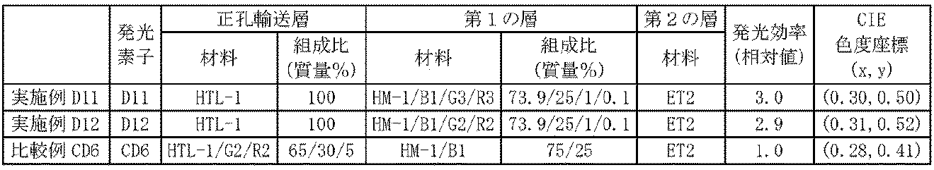
<実施例D13> 発光素子D13の作製と評価
実施例D1の(第1の層の形成)における「化合物HM-1、金属錯体B1、金属錯体G3及び金属錯体R5」に代えて、表6に記載の材料を用い、更に、実施例D1の(第2の層の形成)における「化合物ET1」に代えて、「化合物ET3」を用いた以外は、実施例D1と同様にして、発光素子D13を作製した。
発光素子D13に電圧を印加することによりEL発光が観測された。100cd/m2における発光効率[lm/W]及びCIE色度座標を測定した。 Example D13 Production and Evaluation of Light-Emitting Element D13 Instead of “Compound HM-1, Metal Complex B1, Metal Complex G3, and Metal Complex R5” in (Formation of First Layer) of Example D1, the results are shown in Table 6. Light-emitting element D13 was prepared in the same manner as in Example D1, except that the above-mentioned materials were used and "Compound ET3" was used instead of "Compound ET1" in (Formation of the second layer) of Example D1. Was produced.
EL light emission was observed by applying a voltage to the light emitting device D13. Luminous efficiency [lm / W] at 100 cd / m 2 and CIE chromaticity coordinates were measured.
<比較例CD7> 発光素子CD7の作製と評価
実施例D1の(第1の層の形成)における「化合物HM-1、金属錯体B1、金属錯体G3及び金属錯体R5」に代えて、表6に記載の材料及び組成比(質量%)を用い、実施例D1の(第2の層の形成)における「化合物ET1」に代えて、「化合物ET3」を用い、更に、実施例D1の(正孔輸送層の形成)における「高分子化合物HTL-1」に代えて、表6に記載の材料及び組成比(質量%)を用いた以外は、実施例D1と同様にして、発光素子CD7を作製した。
発光素子CD7に電圧を印加することによりEL発光が観測された。100cd/m2における発光効率[lm/W]及びCIE色度座標を測定した。 <Comparative Example CD7> Production and Evaluation of Light-Emitting Element CD7 In Table 6, instead of “Compound HM-1, Metal Complex B1, Metal Complex G3, and Metal Complex R5” in (Formation of First Layer) of Example D1, Using the materials and composition ratios (% by mass) described, using “Compound ET3” in place of “Compound ET1” in (Formation of the second layer) of Example D1, and further using (hole A light emitting device CD7 was produced in the same manner as in Example D1 except that the material and the composition ratio (% by mass) shown in Table 6 were used instead of the “polymer compound HTL-1” in (Formation of Transport Layer). did.
EL light emission was observed by applying a voltage to the light emitting device CD7. Luminous efficiency [lm / W] at 100 cd / m 2 and CIE chromaticity coordinates were measured.
実施例D13及び比較例CD7の結果を表6に示す。発光素子CD7の発光効率を1.0としたときの発光素子D13の発光効率の相対値を示す。
Table 6 shows the results of Example D13 and Comparative Example CD7. The relative value of the light emission efficiency of the light emitting element D13 when the light emission efficiency of the light emitting element CD7 is 1.0 is shown.
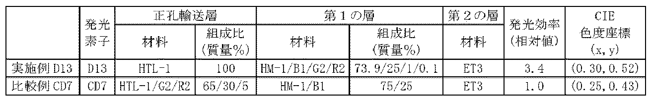
本発明によれば、発光効率が優れる発光素子を提供することができる。発光効率の優れた発光素子は、省資源化、省エネルギー化等の効果がある。
According to the present invention, it is possible to provide a light emitting element having excellent luminous efficiency. A light emitting element having excellent light emitting efficiency has effects such as resource saving and energy saving.
10 発光素子、11 陽極、12 第1の層、13 第2の層、14 陰極。
10 light emitting elements, 11 anodes, 12 first layers, 13 second layers, 14 cathodes.
Claims (13)
- 陽極と、陰極と、前記陽極及び前記陰極の間に設けられた第1の層と、前記陰極及び前記第1の層との間に設けられた第2の層とを有する発光素子であり、
前記第1の層が、式(1)で表される金属錯体の2種以上と、式(2)で表される金属錯体とを含有する層であり、
前記第1の層及び前記第2の層のうちの少なくとも1層が、式(T-1)で表される化合物を含有する、発光素子。

M1は、ロジウム原子、パラジウム原子、イリジウム原子又は白金原子を表す。
n1は1以上の整数を表し、n2は0以上の整数を表す。但し、M1がロジウム原子又はイリジウム原子の場合、n1+n2は3であり、M1がパラジウム原子又は白金原子の場合、n1+n2は2である。
ELは、炭素原子又は窒素原子を表す。ELが複数存在する場合、それらはそれぞれ同一でも異なっていてもよい。
環L1は、6員の芳香族複素環を表し、この環は単一又は複数の置換基を有していてもよい。前記置換基が複数存在する場合、それらは同一でも異なっていてもよく、互いに結合して、それぞれが結合する原子とともに環を形成していてもよい。環L1が複数存在する場合、それらは同一でも異なっていてもよい。
環L2は、芳香族炭化水素環又は芳香族複素環を表し、これらの環は単一又は複数の置換基を有していてもよい。前記置換基が複数存在する場合、それらは同一でも異なっていてもよく、互いに結合して、それぞれが結合する原子とともに環を形成していてもよい。
環L2が複数存在する場合、それらは同一でも異なっていてもよい。
環L1が有していてもよい置換基と環L2が有していてもよい置換基とは、同一でも異なっていてもよく、互いに結合して、それぞれが結合する原子とともに環を形成していてもよい。
但し、環L1及び環L2のうちの少なくとも1つは、置換基として、式(1-T)で表される基を有する。式(1-T)で表される基が複数存在する場合、それらは同一でも異なっていてもよい。
A1-G1-A2は、アニオン性の2座配位子を表す。A1及びA2は、それぞれ独立に、炭素原子、酸素原子又は窒素原子を表し、これらの原子は環を構成する原子であってもよい。G1は、単結合、又は、A1及びA2とともに2座配位子を構成する原子団を表す。A1-G1-A2が複数存在する場合、それらは同一でも異なっていてもよい。]

M2は、ロジウム原子、パラジウム原子、イリジウム原子又は白金原子を表す。
n3は1以上の整数を表し、n4は0以上の整数を表す。但し、M2がロジウム原子又はイリジウム原子の場合、n3+n4は3であり、M2がパラジウム原子又は白金原子の場合、n3+n4は2である。
E1及びE2は、それぞれ独立に、炭素原子又は窒素原子を表す。E1及びE2が複数存在する場合、それらはそれぞれ同一でも異なっていてもよい。
環R1は、5員の芳香族複素環を表し、この環は単一又は複数の置換基を有していてもよい。前記置換基が複数存在する場合、それらは同一でも異なっていてもよく、互いに結合して、それぞれが結合する原子とともに環を形成していてもよい。環R1が複数存在する場合、それらは同一でも異なっていてもよい。
環R2は、芳香族炭化水素環又は芳香族複素環を表し、これらの環は単一又は複数の置換基を有していてもよい。前記置換基が複数存在する場合、それらは同一でも異なっていてもよく、互いに結合して、それぞれが結合する原子とともに環を形成していてもよい。
環R2が複数存在する場合、それらは同一でも異なっていてもよい。
環R1が有していてもよい置換基と環R2が有していてもよい置換基とは、同一でも異なっていてもよく、互いに結合して、それぞれが結合する原子とともに環を形成していてもよい。
A3-G2-A4は、アニオン性の2座配位子を表す。A3及びA4は、それぞれ独立に、炭素原子、酸素原子又は窒素原子を表し、これらの原子は環を構成する原子であってもよい。G2は、単結合、又は、A3及びA4とともに2座配位子を構成する原子団を表す。A3-G2-A4が複数存在する場合、それらは同一でも異なっていてもよい。]


nT1は、0以上5以下の整数を表す。nT1が複数存在する場合、それらは同一でも異なっていてもよい。
nT2は、1以上10以下の整数を表す。
ArT1は、環内に二重結合を有さない窒素原子及び=N-で表される基を含む、縮合環の1価の複素環基であり、該基は単一又は複数の置換基を有していてもよく、前記置換基が複数存在する場合、それらは同一でも異なっていてもよく、互いに結合して、それぞれが結合する原子とともに環を形成していてもよい。ArT1が複数存在する場合、それらは同一でも異なっていてもよい。
LT1は、アルキレン基、シクロアルキレン基、アリーレン基、2価の複素環基、-NRT1’-で表される基、酸素原子又は硫黄原子を表し、これらの基は単一又は複数の置換基を有していてもよく、前記置換基が複数存在する場合、それらは同一でも異なっていてもよく、互いに結合して、それぞれが結合する原子とともに環を形成していてもよい。
RT1’は、水素原子、アルキル基、シクロアルキル基、アリール基又は1価の複素環基を表し、これらの基は単一又は複数の置換基を有していてもよく、前記置換基が複数存在する場合、それらは同一でも異なっていてもよく、互いに結合して、それぞれが結合する原子とともに環を形成していてもよい。LT1が複数存在する場合、それらは同一でも異なっていてもよい。
ArT2は、芳香族炭化水素基又は複素環基を表し、これらの基は単一又は複数の置換基を有していてもよく、前記置換基が複数存在する場合、それらは同一でも異なっていてもよく、互いに結合して、それぞれが結合する原子とともに環を形成していてもよい。] A light emitting device having an anode, a cathode, a first layer provided between the anode and the cathode, and a second layer provided between the cathode and the first layer,
The first layer is a layer containing two or more kinds of the metal complex represented by the formula (1) and the metal complex represented by the formula (2),
A light emitting device, wherein at least one layer of the first layer and the second layer contains a compound represented by the formula (T-1).
M 1 represents a rhodium atom, a palladium atom, an iridium atom or a platinum atom.
n 1 represents an integer of 1 or more, and n 2 represents an integer of 0 or more. However, when M 1 is a rhodium atom or an iridium atom, n 1 + n 2 is 3, and when M 1 is a palladium atom or a platinum atom, n 1 + n 2 is 2.
E L represents a carbon atom or a nitrogen atom. If the E L there are a plurality, or different in each of them the same.
Ring L 1 represents a 6-membered aromatic heterocycle, and this ring may have a single or a plurality of substituents. When a plurality of substituents are present, they may be the same or different and may be bonded to each other to form a ring with the atoms to which they are bonded. When there are a plurality of rings L 1 , they may be the same or different.
Ring L 2 represents an aromatic hydrocarbon ring or an aromatic heterocycle, and these rings may have a single or a plurality of substituents. When a plurality of substituents are present, they may be the same or different and may be bonded to each other to form a ring with the atoms to which they are bonded.
When multiple rings L 2 are present, they may be the same or different.
The substituent that the ring L 1 may have and the substituent that the ring L 2 may have may be the same or different, and they are bonded to each other to form a ring together with the atom to which they are bonded. You may have.
However, at least one of the ring L 1 and the ring L 2 has a group represented by the formula (1-T) as a substituent. When there are a plurality of groups represented by formula (1-T), they may be the same or different.
A 1 -G 1 -A 2 represents an anionic bidentate ligand. A 1 and A 2 each independently represent a carbon atom, an oxygen atom or a nitrogen atom, and these atoms may be atoms constituting a ring. G 1 represents a single bond or an atomic group forming a bidentate ligand together with A 1 and A 2 . When there are a plurality of A 1 -G 1 -A 2 , they may be the same or different. ]
M 2 represents a rhodium atom, a palladium atom, an iridium atom or a platinum atom.
n 3 represents an integer of 1 or more, and n 4 represents an integer of 0 or more. However, when M 2 is a rhodium atom or an iridium atom, n 3 + n 4 is 3, and when M 2 is a palladium atom or a platinum atom, n 3 + n 4 is 2.
E 1 and E 2 each independently represent a carbon atom or a nitrogen atom. When a plurality of E 1 and E 2 are present, they may be the same or different.
Ring R 1 represents a 5-membered aromatic heterocycle, and this ring may have a single or a plurality of substituents. When a plurality of substituents are present, they may be the same or different and may be bonded to each other to form a ring with the atoms to which they are bonded. When multiple rings R 1 are present, they may be the same or different.
Ring R 2 represents an aromatic hydrocarbon ring or an aromatic heterocycle, and these rings may have a single or a plurality of substituents. When a plurality of substituents are present, they may be the same or different and may be bonded to each other to form a ring with the atoms to which they are bonded.
When there are a plurality of rings R 2 , they may be the same or different.
The substituent that the ring R 1 may have and the substituent that the ring R 2 may have may be the same or different, and they are bonded to each other to form a ring together with the atom to which they are bonded. You may have.
A 3 -G 2 -A 4 represents an anionic bidentate ligand. A 3 and A 4 each independently represent a carbon atom, an oxygen atom or a nitrogen atom, and these atoms may be atoms constituting a ring. G 2 represents a single bond or an atomic group forming a bidentate ligand together with A 3 and A 4 . When there are a plurality of A 3 -G 2 -A 4 , they may be the same or different. ]
n T1 represents an integer of 0 or more and 5 or less. When a plurality of n T1s are present, they may be the same or different.
n T2 represents an integer of 1 or more and 10 or less.
Ar T1 is a fused ring monovalent heterocyclic group containing a nitrogen atom having no double bond in the ring and a group represented by ═N—, and the group is a single or plural substituents. When there are a plurality of substituents, they may be the same or different, and they may be bonded to each other to form a ring together with the atom to which they are bonded. When a plurality of Ar T1s are present, they may be the same or different.
L T1 is an alkylene group, a cycloalkylene group, an arylene group, a divalent heterocyclic group, -NR T1 '- represents a group represented by an oxygen atom or a sulfur atom, the these groups single or multiple substitutions When it has a plurality of substituents, they may be the same or different and may be bonded to each other to form a ring together with the atom to which they are bonded.
R T1 ′ represents a hydrogen atom, an alkyl group, a cycloalkyl group, an aryl group or a monovalent heterocyclic group, and these groups may have a single or a plurality of substituents, and the substituent is When a plurality of them are present, they may be the same or different and may be bonded to each other to form a ring with the atom to which each is bonded. When there are a plurality of L T1 , they may be the same or different.
Ar T2 represents an aromatic hydrocarbon group or a heterocyclic group, and these groups may have a single or a plurality of substituents, and when there are a plurality of the substituents, they may be the same or different. Alternatively, they may be bonded to each other to form a ring together with the atoms to which they are bonded. ] - 前記第2の層が、前記式(T-1)で表される化合物を含有する、請求項1に記載の発光素子。 The light emitting device according to claim 1, wherein the second layer contains a compound represented by the formula (T-1).
- 前記ArT1が、式(T1-1)で表される基である、請求項1又は2に記載の発光素子。

XT1は、単結合、酸素原子、硫黄原子、-N(RXT1)-で表される基、又は、-C(RXT1’)2-で表される基を表す。RXT1及びRXT1’は、それぞれ独立に、水素原子、アルキル基、シクロアルキル基、アルコキシ基、シクロアルコキシ基、アリール基、アリールオキシ基、1価の複素環基、置換アミノ基、ハロゲン原子又はシアノ基を表し、これらの基は単一又は複数の置換基を有していてもよく、前記置換基が複数存在する場合、それらは同一でも異なっていてもよく、互いに結合して、それぞれが結合する原子とともに環を形成していてもよい。複数存在するRXT1’は、同一でも異なっていてもよく、互いに結合して、それぞれが結合する原子とともに環を形成していてもよい。
環RT1及び環RT2は、それぞれ独立に、芳香族炭化水素環又は複素環を表し、これらの環は単一又は複数の置換基を有していてもよく、前記置換基が複数存在する場合、それらは同一でも異なっていてもよく、互いに結合して、それぞれが結合する原子とともに環を形成していてもよい。
但し、環RT1及び環RT2のうちの少なくとも一つは、環内に=N-で表される基を含む複素環であり、該環は単一又は複数の置換基を有していてもよく、前記置換基が複数存在する場合、それらは同一でも異なっていてもよく、互いに結合して、それぞれが結合する原子とともに環を形成していてもよい。] The light emitting device according to claim 1, wherein the Ar T1 is a group represented by the formula (T1-1).
X T1 represents a single bond, an oxygen atom, a sulfur atom, a group represented by —N (R XT1 ) —, or a group represented by —C (R XT1 ′ ) 2 —. R XT1 and R XT1 ′ are each independently a hydrogen atom, an alkyl group, a cycloalkyl group, an alkoxy group, a cycloalkoxy group, an aryl group, an aryloxy group, a monovalent heterocyclic group, a substituted amino group, a halogen atom or Represents a cyano group, these groups may have a single or a plurality of substituents, when there are a plurality of the substituents, they may be the same or different, and they are bonded to each other, It may form a ring together with the atom to be bonded. The plurality of R XT1 ′ s that are present may be the same or different and may be bonded to each other to form a ring together with the atom to which each is bonded.
The ring R T1 and the ring R T2 each independently represent an aromatic hydrocarbon ring or a heterocycle, and these rings may have a single or a plurality of substituents, and a plurality of the above substituents are present. In this case, they may be the same or different and may be bonded to each other to form a ring with the atom to which each is bonded.
Provided that at least one of the ring R T1 and the ring R T2 is a heterocycle containing a group represented by ═N— in the ring, and the ring has a single or a plurality of substituents. Alternatively, when there are a plurality of the above-mentioned substituents, they may be the same or different, and they may be bonded to each other to form a ring with the atoms to which they are bonded. ] - 前記環RT1が、芳香族炭化水素環又は環内に=N-で表される基を含む複素環であり、これらの環は単一又は複数の置換基を有していてもよく、且つ、前記環RT2が、環内に=N-で表される基を含む複素環であり、該環は単一又は複数の置換基を有していてもよい、請求項3に記載の発光素子。 The ring R T1 is an aromatic hydrocarbon ring or a heterocycle containing a group represented by ═N— in the ring, and these rings may have a single or a plurality of substituents, and The luminescence according to claim 3, wherein the ring R T2 is a heterocycle containing a group represented by = N- in the ring, and the ring may have a single or a plurality of substituents. element.
- 前記環RT1が、単環式の芳香族炭化水素環又は環内に=N-で表される基を含む単環式の複素環であり、これらの環は単一又は複数の置換基を有していてもよく、且つ、前記環RT2が、環内に=N-で表される基を含む単環式の複素環であり、該環は単一又は複数の置換基を有していてもよい、請求項4に記載の発光素子。 The ring R T1 is a monocyclic aromatic hydrocarbon ring or a monocyclic heterocycle containing a group represented by ═N— in the ring, and these rings each have a single or a plurality of substituents. And the ring R T2 is a monocyclic heterocycle containing a group represented by ═N— in the ring, and the ring has a single or a plurality of substituents. The light emitting device according to claim 4, which may be included.
- 前記環RT1が、ベンゼン環、ピリジン環又はジアザベンゼン環であり、これらの環は単一又は複数の置換基を有していてもよく、且つ、前記環RT2が、ピリジン環又はジアザベンゼン環であり、これらの環は単一又は複数の置換基を有していてもよい、請求項5に記載の発光素子。 The ring R T1 is a benzene ring, a pyridine ring or a diazabenzene ring, and these rings may have a single or plural substituents, and the ring R T2 is a pyridine ring or a diazabenzene ring. The light emitting device according to claim 5, wherein these rings may have a single or a plurality of substituents.
- 前記環L1が、ピリジン環、ジアザベンゼン環、アザナフタレン環又はジアザナフタレン環であり、これらの環は単一又は複数の置換基を有していてもよく、且つ、前記環L2が、ベンゼン環、ピリジン環又はジアザベンゼン環であり、これらの環は単一又は複数の置換基を有していてもよい、請求項1~6のいずれか一項に記載の発光素子。 The ring L 1 is a pyridine ring, a diazabenzene ring, an azanaphthalene ring or a diazanaphthalene ring, and these rings may have a single or a plurality of substituents, and the ring L 2 is 7. The light emitting device according to claim 1, which is a benzene ring, a pyridine ring or a diazabenzene ring, and these rings may have a single or a plurality of substituents.
- 前記式(1)で表される金属錯体の発光スペクトルの最大ピーク波長が495nm以上750nm未満である、請求項1~7のいずれか一項に記載の発光素子。 The light emitting device according to any one of claims 1 to 7, wherein a maximum peak wavelength of an emission spectrum of the metal complex represented by the formula (1) is 495 nm or more and less than 750 nm.
- 前記環R1が、ジアゾール環又はトリアゾール環であり、これらの環は単一又は複数の置換基を有していてもよく、且つ、前記環R2が、ベンゼン環、ピリジン環又はジアザベンゼン環であり、これらの環は単一又は複数の置換基を有していてもよい、請求項1~8のいずれか一項に記載の発光素子。 The ring R 1 is a diazole ring or a triazole ring, these rings may have a single or a plurality of substituents, and the ring R 2 is a benzene ring, a pyridine ring or a diazabenzene ring. The light emitting device according to any one of claims 1 to 8, wherein these rings may have a single or a plurality of substituents.
- 前記式(2)で表される金属錯体の発光スペクトルの最大ピーク波長が380nm以上495nm未満である、請求項1~9のいずれか一項に記載の発光素子。 The light emitting device according to any one of claims 1 to 9, wherein a maximum peak wavelength of an emission spectrum of the metal complex represented by the formula (2) is 380 nm or more and less than 495 nm.
- 前記第1の層が、式(H-1)で表される化合物を更に含有する、請求項1~10のいずれか一項に記載の発光素子。

ArH1及びArH2は、それぞれ独立に、アリール基、1価の複素環基又は置換アミノ基を表し、これらの基は単一又は複数の置換基を有していてもよい。前記置換基が複数存在する場合、それらは同一でも異なっていてもよく、互いに結合して、それぞれが結合する原子とともに環を形成していてもよい。
nH1は、0以上の整数を表す。
LH1は、アリーレン基、2価の複素環基、アルキレン基又はシクロアルキレン基を表し、これらの基は単一又は複数の置換基を有していてもよい。前記置換基が複数存在する場合、それらは同一でも異なっていてもよく、互いに結合して、それぞれが結合する原子とともに環を形成していてもよい。LH1が複数存在する場合、それらは同一でも異なっていてもよい。] The light emitting device according to any one of claims 1 to 10, wherein the first layer further contains a compound represented by the formula (H-1).
Ar H1 and Ar H2 each independently represent an aryl group, a monovalent heterocyclic group or a substituted amino group, and these groups may have a single or a plurality of substituents. When a plurality of substituents are present, they may be the same or different and may be bonded to each other to form a ring with the atoms to which they are bonded.
n H1 represents an integer of 0 or more.
L H1 represents an arylene group, a divalent heterocyclic group, an alkylene group or a cycloalkylene group, and these groups may have a single or a plurality of substituents. When a plurality of substituents are present, they may be the same or different and may be bonded to each other to form a ring with the atoms to which they are bonded. When a plurality of L H1 are present, they may be the same or different. ] - 前記第1の層が、正孔輸送材料、正孔注入材料、電子輸送材料、電子注入材料、発光材料及び酸化防止剤からなる群より選ばれる少なくとも1種を更に含有する、請求項1~11のいずれか一項に記載の発光素子。 12. The first layer further contains at least one selected from the group consisting of a hole transport material, a hole injection material, an electron transport material, an electron injection material, a light emitting material and an antioxidant. The light emitting device according to any one of 1.
- 前記第1の層と、前記第2の層とが、隣接している、請求項1~12のいずれか一項に記載の発光素子。 The light emitting device according to any one of claims 1 to 12, wherein the first layer and the second layer are adjacent to each other.
Applications Claiming Priority (2)
| Application Number | Priority Date | Filing Date | Title |
|---|---|---|---|
| JP2018200623 | 2018-10-25 | ||
| JP2018-200623 | 2018-10-25 |
Publications (1)
| Publication Number | Publication Date |
|---|---|
| WO2020084919A1 true WO2020084919A1 (en) | 2020-04-30 |
Family
ID=70332219
Family Applications (1)
| Application Number | Title | Priority Date | Filing Date |
|---|---|---|---|
| PCT/JP2019/034947 WO2020084919A1 (en) | 2018-10-25 | 2019-09-05 | Light-emitting element |
Country Status (2)
| Country | Link |
|---|---|
| JP (1) | JP6692980B2 (en) |
| WO (1) | WO2020084919A1 (en) |
Citations (6)
| Publication number | Priority date | Publication date | Assignee | Title |
|---|---|---|---|---|
| WO2010001830A1 (en) * | 2008-07-01 | 2010-01-07 | コニカミノルタホールディングス株式会社 | White light-emitting organic electroluminescent element, illuminating device and display device |
| JP2013045923A (en) * | 2011-08-25 | 2013-03-04 | Konica Minolta Holdings Inc | Organic electroluminescent element, lighting device, and display device |
| WO2013042446A1 (en) * | 2011-09-21 | 2013-03-28 | コニカミノルタホールディングス株式会社 | Organic electroluminescent element, display device, and illumination device |
| JP2016207954A (en) * | 2015-04-28 | 2016-12-08 | コニカミノルタ株式会社 | Organic electroluminescent element and organic electroluminescent element material |
| JP2017098416A (en) * | 2015-11-25 | 2017-06-01 | コニカミノルタ株式会社 | Organic electroluminescent element material, organic electroluminescent element, display device and illuminating device |
| JP2018083940A (en) * | 2016-11-14 | 2018-05-31 | 住友化学株式会社 | Composition and light emitting element prepared therewith |
Family Cites Families (9)
| Publication number | Priority date | Publication date | Assignee | Title |
|---|---|---|---|---|
| JPH07211457A (en) * | 1994-01-21 | 1995-08-11 | Chisso Corp | Organic thin-film electroluminescent element |
| WO2009102054A1 (en) * | 2008-02-15 | 2009-08-20 | Idemitsu Kosan Co., Ltd. | Organic luminescent medium and organic el device |
| JP5516317B2 (en) * | 2009-10-22 | 2014-06-11 | 住友化学株式会社 | Organic electroluminescence device |
| JP5722000B2 (en) * | 2010-01-15 | 2015-05-20 | ユー・ディー・シー アイルランド リミテッド | Charge transport material and organic electroluminescent device |
| JP6212098B2 (en) * | 2010-01-15 | 2017-10-11 | ユー・ディー・シー アイルランド リミテッド | Organic electroluminescence device |
| US8710493B2 (en) * | 2010-05-24 | 2014-04-29 | Idemitsu Kosan Co., Ltd. | Organic electroluminescent element |
| KR20230051628A (en) * | 2014-09-30 | 2023-04-18 | 가부시키가이샤 한도오따이 에네루기 켄큐쇼 | Light-emitting element, display device, electronic device, and lighting device |
| US10290816B2 (en) * | 2015-11-16 | 2019-05-14 | The Regents Of The University Of Michigan | Organic electroluminescent materials and devices |
| JP6935287B2 (en) * | 2016-09-29 | 2021-09-15 | 東京応化工業株式会社 | Hydrogen barrier agent, composition for forming hydrogen barrier membrane, hydrogen barrier membrane, method for producing hydrogen barrier membrane, and electronic device |
-
2019
- 2019-08-26 JP JP2019153332A patent/JP6692980B2/en not_active Expired - Fee Related
- 2019-09-05 WO PCT/JP2019/034947 patent/WO2020084919A1/en active Application Filing
Patent Citations (6)
| Publication number | Priority date | Publication date | Assignee | Title |
|---|---|---|---|---|
| WO2010001830A1 (en) * | 2008-07-01 | 2010-01-07 | コニカミノルタホールディングス株式会社 | White light-emitting organic electroluminescent element, illuminating device and display device |
| JP2013045923A (en) * | 2011-08-25 | 2013-03-04 | Konica Minolta Holdings Inc | Organic electroluminescent element, lighting device, and display device |
| WO2013042446A1 (en) * | 2011-09-21 | 2013-03-28 | コニカミノルタホールディングス株式会社 | Organic electroluminescent element, display device, and illumination device |
| JP2016207954A (en) * | 2015-04-28 | 2016-12-08 | コニカミノルタ株式会社 | Organic electroluminescent element and organic electroluminescent element material |
| JP2017098416A (en) * | 2015-11-25 | 2017-06-01 | コニカミノルタ株式会社 | Organic electroluminescent element material, organic electroluminescent element, display device and illuminating device |
| JP2018083940A (en) * | 2016-11-14 | 2018-05-31 | 住友化学株式会社 | Composition and light emitting element prepared therewith |
Also Published As
| Publication number | Publication date |
|---|---|
| JP6692980B2 (en) | 2020-05-13 |
| JP2020072256A (en) | 2020-05-07 |
Similar Documents
| Publication | Publication Date | Title |
|---|---|---|
| WO2020084924A1 (en) | Light-emitting element | |
| WO2020203209A1 (en) | Light-emitting element and composition for light-emitting element | |
| WO2020084923A1 (en) | Light-emitting element | |
| JP6692980B2 (en) | Light emitting element | |
| JP6651041B1 (en) | Light emitting element | |
| JP6672518B1 (en) | Light emitting element | |
| JP6600064B1 (en) | Light emitting element | |
| JP6589032B1 (en) | Light emitting element | |
| JP2020107806A (en) | Composition for light-emitting element and method for manufacturing light-emitting element | |
| KR102191197B1 (en) | Composition for light-emitting device, method for producing composition for light-emitting device, method for evaluating composition for light-emitting device, method for producing light-emitting device and light-emitting device | |
| JP2020077853A (en) | Light emitting element | |
| JP2020077852A (en) | Light-emitting device | |
| JP6688868B1 (en) | Light emitting device composition and method for producing light emitting device | |
| KR102201526B1 (en) | Composition for light-emitting element and light-emitting element containing same | |
| JP2020109874A (en) | Light emitting element composition and light emitting element including the same | |
| JP2020109825A (en) | Light emitting element composition and light emitting element including the same | |
| WO2020137445A1 (en) | Composition for luminescent element, and luminescent element containing same | |
| JP2020109828A (en) | Light emitting element composition and light emitting element including the same | |
| JP2020109826A (en) | Light emitting element composition and light emitting element including the same | |
| JP2020107822A (en) | Composition for light-emitting element and light-emitting element containing the same |
Legal Events
| Date | Code | Title | Description |
|---|---|---|---|
| 121 | Ep: the epo has been informed by wipo that ep was designated in this application |
Ref document number: 19874949 Country of ref document: EP Kind code of ref document: A1 |
|
| NENP | Non-entry into the national phase |
Ref country code: DE |
|
| 122 | Ep: pct application non-entry in european phase |
Ref document number: 19874949 Country of ref document: EP Kind code of ref document: A1 |