WO2020075862A1 - Procédé de codage de données tridimensionnelles, procédé de décodage de données tridimensionnelles, dispositif de codage de données tridimensionnelles et dispositif de décodage de données tridimensionnelles - Google Patents
Procédé de codage de données tridimensionnelles, procédé de décodage de données tridimensionnelles, dispositif de codage de données tridimensionnelles et dispositif de décodage de données tridimensionnelles Download PDFInfo
- Publication number
- WO2020075862A1 WO2020075862A1 PCT/JP2019/040331 JP2019040331W WO2020075862A1 WO 2020075862 A1 WO2020075862 A1 WO 2020075862A1 JP 2019040331 W JP2019040331 W JP 2019040331W WO 2020075862 A1 WO2020075862 A1 WO 2020075862A1
- Authority
- WO
- WIPO (PCT)
- Prior art keywords
- dimensional data
- dimensional
- information
- encoding
- data
- Prior art date
Links
Images


Classifications
-
- G—PHYSICS
- G06—COMPUTING; CALCULATING OR COUNTING
- G06T—IMAGE DATA PROCESSING OR GENERATION, IN GENERAL
- G06T9/00—Image coding
- G06T9/001—Model-based coding, e.g. wire frame
-
- G—PHYSICS
- G06—COMPUTING; CALCULATING OR COUNTING
- G06T—IMAGE DATA PROCESSING OR GENERATION, IN GENERAL
- G06T9/00—Image coding
-
- G—PHYSICS
- G06—COMPUTING; CALCULATING OR COUNTING
- G06T—IMAGE DATA PROCESSING OR GENERATION, IN GENERAL
- G06T9/00—Image coding
- G06T9/004—Predictors, e.g. intraframe, interframe coding
-
- H—ELECTRICITY
- H04—ELECTRIC COMMUNICATION TECHNIQUE
- H04N—PICTORIAL COMMUNICATION, e.g. TELEVISION
- H04N19/00—Methods or arrangements for coding, decoding, compressing or decompressing digital video signals
- H04N19/46—Embedding additional information in the video signal during the compression process
- H04N19/463—Embedding additional information in the video signal during the compression process by compressing encoding parameters before transmission
-
- H—ELECTRICITY
- H04—ELECTRIC COMMUNICATION TECHNIQUE
- H04N—PICTORIAL COMMUNICATION, e.g. TELEVISION
- H04N19/00—Methods or arrangements for coding, decoding, compressing or decompressing digital video signals
- H04N19/50—Methods or arrangements for coding, decoding, compressing or decompressing digital video signals using predictive coding
- H04N19/597—Methods or arrangements for coding, decoding, compressing or decompressing digital video signals using predictive coding specially adapted for multi-view video sequence encoding
Definitions
- the present disclosure relates to a three-dimensional data encoding method, a three-dimensional data decoding method, a three-dimensional data encoding device, and a three-dimensional data decoding device.
- ⁇ In a wide range of fields, such as computer vision, map information, monitoring, infrastructure inspection, and video distribution for autonomous operation of automobiles or robots, devices or services utilizing three-dimensional data are expected to spread in the future.
- the three-dimensional data is acquired by various methods such as a distance sensor such as a range finder, a stereo camera, or a combination of a plurality of monocular cameras.
- One of the three-dimensional data representation methods is a representation method called a point cloud that represents the shape of a three-dimensional structure by a point group in a three-dimensional space.
- the point cloud stores the position and color of the point cloud.
- Point clouds are expected to become mainstream as a method of expressing three-dimensional data, but point clouds have a very large data volume. Therefore, in the storage or transmission of three-dimensional data, it is necessary to compress the amount of data by encoding, as in the case of two-dimensional moving images (for example, MPEG-4 @ AVC or HEVC standardized by MPEG). Become.
- ⁇ Point cloud compression ⁇ is partially supported by a public library (Point ⁇ Cloud ⁇ Library) that performs point cloud related processing.
- Patent Document 1 a technique for searching for and displaying facilities located around the vehicle using three-dimensional map data is known (for example, see Patent Document 1).
- -It is desired that the processing amount can be reduced in the encoding process or the decoding process of three-dimensional data.
- the present disclosure aims to provide a three-dimensional data encoding method, a three-dimensional data decoding method, a three-dimensional data encoding device, or a three-dimensional data decoding device that can reduce the processing amount.
- a three-dimensional data encoding method divides a plurality of three-dimensional points included in point cloud data into processing units each including one or more three-dimensional points, and includes the processing unit as a processing target.
- a bitstream is generated by encoding the attribute information of the three-dimensional point to be processed with reference to the encoded processing unit.
- a three-dimensional data decoding method In a three-dimensional data decoding method according to an aspect of the present disclosure, a plurality of three-dimensional points included in point cloud data is divided from a bitstream, and a processing unit each including one or more three-dimensional points is encoded.
- the encoded data is acquired, and the attribute information of the processing target three-dimensional point included in the processing unit of the processing target is decoded from the encoded data by referring to the decoded processing unit.
- the present disclosure can provide a three-dimensional data encoding method, a three-dimensional data decoding method, a three-dimensional data encoding device, or a three-dimensional data decoding device that can reduce the processing amount.
- FIG. 1 is a diagram showing a structure of encoded three-dimensional data according to the first embodiment.
- FIG. 2 is a diagram showing an example of a prediction structure between SPCs belonging to the lowest layer of GOS according to the first embodiment.
- FIG. 3 is a diagram showing an example of an inter-layer prediction structure according to the first embodiment.
- FIG. 4 is a diagram showing an example of a GOS encoding order according to the first embodiment.
- FIG. 5 is a diagram showing an example of a GOS encoding order according to the first embodiment.
- FIG. 6 is a block diagram of the three-dimensional data encoding device according to the first embodiment.
- FIG. 7 is a flowchart of the encoding process according to the first embodiment.
- FIG. 1 is a diagram showing a structure of encoded three-dimensional data according to the first embodiment.
- FIG. 2 is a diagram showing an example of a prediction structure between SPCs belonging to the lowest layer of GOS according to the first embodiment.
- FIG. 3 is
- FIG. 8 is a block diagram of the three-dimensional data decoding device according to the first embodiment.
- FIG. 9 is a flowchart of the decoding process according to the first embodiment.
- FIG. 10 is a diagram showing an example of the meta information according to the first embodiment.
- FIG. 11 is a diagram showing a configuration example of the SWLD according to the second embodiment.
- FIG. 12 is a diagram showing an operation example of the server and the client according to the second embodiment.
- FIG. 13 is a diagram showing an operation example of the server and the client according to the second embodiment.
- FIG. 14 is a diagram showing an operation example of the server and the client according to the second embodiment.
- FIG. 15 is a diagram showing an operation example of the server and the client according to the second embodiment.
- FIG. 15 is a diagram showing an operation example of the server and the client according to the second embodiment.
- FIG. 16 is a block diagram of the three-dimensional data encoding device according to the second embodiment.
- FIG. 17 is a flowchart of the encoding process according to the second embodiment.
- FIG. 18 is a block diagram of the three-dimensional data decoding device according to the second embodiment.
- FIG. 19 is a flowchart of the decoding process according to the second embodiment.
- FIG. 20 is a diagram showing a configuration example of the WLD according to the second embodiment.
- FIG. 21 is a diagram illustrating an example of the WLD octree structure according to the second embodiment.
- FIG. 22 is a diagram showing a configuration example of the SWLD according to the second embodiment.
- FIG. 23 is a diagram showing an example of an octree tree structure of SWLD according to the second embodiment.
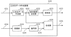
- FIG. 24 is a block diagram of the three-dimensional data creation device according to the third embodiment.
- FIG. 25 is a block diagram of the three-dimensional data transmission device according to the third embodiment.
- FIG. 26 is a block diagram of the three-dimensional information processing device according to the fourth embodiment.
- FIG. 27 is a block diagram of the three-dimensional data creation device according to the fifth embodiment.
- FIG. 28 is a diagram showing the configuration of the system according to the sixth embodiment.
- FIG. 29 is a block diagram of a client device according to the sixth embodiment.
- FIG. 30 is a block diagram of a server according to the sixth embodiment.
- FIG. 31 is a flowchart of the three-dimensional data creation processing by the client device according to the sixth embodiment.
- FIG. 32 is a flowchart of sensor information transmission processing by the client device according to the sixth embodiment.
- FIG. 33 is a flowchart of the three-dimensional data creation processing by the server according to the sixth embodiment.
- FIG. 34 is a flowchart of the three-dimensional map transmission processing by the server according to the sixth embodiment.
- FIG. 35 is a diagram showing a configuration of a modified example of the system according to the sixth embodiment.
- FIG. 36 is a diagram showing configurations of the server and the client device according to the sixth embodiment.
- FIG. 37 is a block diagram of the three-dimensional data encoding device according to the seventh embodiment.
- FIG. 38 is a diagram showing an example of the prediction residual according to the seventh embodiment.
- FIG. 39 is a diagram showing an example of a volume according to the seventh embodiment.
- FIG. 39 is a diagram showing an example of a volume according to the seventh embodiment.
- FIG. 40 is a diagram showing an example of an octree tree representation of a volume according to the seventh embodiment.
- FIG. 41 is a diagram showing an example of a bit string of a volume according to the seventh embodiment.
- FIG. 42 is a diagram showing an example of an octree tree representation of a volume according to the seventh embodiment.
- FIG. 43 is a diagram showing an example of a volume according to the seventh embodiment.
- FIG. 44 is a diagram for explaining the intra prediction process according to the seventh embodiment.
- FIG. 45 is a diagram for explaining the rotation and translation processing according to the seventh embodiment.
- FIG. 46 is a diagram showing a syntax example of an RT application flag and RT information according to the seventh embodiment.
- FIG. 47 is a diagram for explaining the inter prediction process according to the seventh embodiment.
- FIG. 41 is a diagram showing an example of a bit string of a volume according to the seventh embodiment.
- FIG. 42 is a diagram showing an example of an octree tree representation of a
- FIG. 48 is a block diagram of a three-dimensional data decoding device according to the seventh embodiment.
- FIG. 49 is a flowchart of the three-dimensional data encoding process by the three-dimensional data encoding device according to the seventh embodiment.
- FIG. 50 is a flowchart of the three-dimensional data decoding process by the three-dimensional data decoding device according to the seventh embodiment.
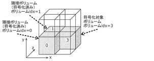
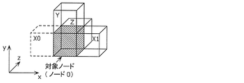
- FIG. 51 is a diagram showing reference relationships in the octree structure according to the eighth embodiment.
- FIG. 52 is a diagram showing a reference relationship in the spatial area according to the eighth embodiment.
- FIG. 53 is a diagram showing an example of an adjacent reference node according to the eighth embodiment.
- FIG. 54 is a diagram showing a relationship between a parent node and nodes according to the eighth embodiment.
- FIG. 49 is a flowchart of the three-dimensional data encoding process by the three-dimensional data encoding device according to the seventh embodiment.
- FIG. 50 is a flowchart of the three-dimensional data decoding
- FIG. 55 is a diagram showing an example of the occupancy code of the parent node according to the eighth embodiment.
- FIG. 56 is a block diagram of a three-dimensional data encoding device according to the eighth embodiment.
- FIG. 57 is a block diagram of a three-dimensional data decoding device according to the eighth embodiment.
- FIG. 58 is a flowchart of the three-dimensional data encoding process according to the eighth embodiment.
- FIG. 59 is a flowchart of the three-dimensional data decoding process according to the eighth embodiment.
- FIG. 60 is a diagram showing an example of coding table switching according to the eighth embodiment.
- FIG. 61 is a diagram showing a reference relationship in the spatial region according to the first modification of the eighth embodiment.
- FIG. 62 is a diagram showing a syntax example of header information according to the first modification of the eighth embodiment.
- FIG. 63 is a diagram showing a syntax example of header information according to the first modification of the eighth embodiment.
- FIG. 64 is a diagram showing an example of an adjacent reference node according to the second modification of the eighth embodiment.
- FIG. 65 is a diagram showing an example of a target node and an adjacent node according to the second modification of the eighth embodiment.
- FIG. 66 is a diagram showing a reference relationship in the octree structure according to the third modification of the eighth embodiment.
- FIG. 67 is a diagram showing a reference relationship in the spatial area according to the third modification of the eighth embodiment.
- FIG. 68 is a diagram showing an example of three-dimensional points according to the ninth embodiment.
- FIG. 69 is a diagram showing a setting example of LoD according to the ninth embodiment.
- FIG. 70 is a diagram showing an example of thresholds used for setting LoD according to the ninth embodiment.
- FIG. 71 is a diagram showing an example of attribute information used for predicted values according to the ninth embodiment.
- FIG. 72 is a diagram showing an example of the exponential Golomb code according to the ninth embodiment.
- FIG. 73 is a diagram showing processing for the exponential Golomb code according to the ninth embodiment.
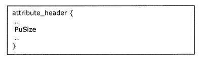
- FIG. 74 is a diagram showing a syntax example of an attribute header according to the ninth embodiment.
- FIG. 75 is a diagram showing a syntax example of attribute data according to the ninth embodiment.
- FIG. 76 is a flowchart of the three-dimensional data encoding process according to the ninth embodiment.
- FIG. 77 is a flowchart of the attribute information encoding process according to the ninth embodiment.
- FIG. 78 is a diagram showing processing for an exponential Golomb code according to the ninth embodiment.
- FIG. 79 is a diagram showing an example of a reverse lookup table showing the relationship between the remaining code and its value according to the ninth embodiment.
- FIG. 80 is a flowchart of the three-dimensional data decoding process according to the ninth embodiment.
- FIG. 81 is a flowchart of the attribute information decoding process according to the ninth embodiment.
- FIG. 82 is a block diagram of a three-dimensional data encoding device according to the ninth embodiment.
- FIG. 83 is a block diagram of a three-dimensional data decoding device according to the ninth embodiment.
- FIG. 84 is a flowchart of the three-dimensional data encoding process according to the ninth embodiment.
- FIG. 85 is a flowchart of the three-dimensional data decoding process according to the ninth embodiment.
- FIG. 86 is a diagram showing a first example of a table showing prediction values calculated in each prediction mode according to the tenth embodiment.
- FIG. 87 is a diagram showing an example of attribute information used for predicted values according to the tenth embodiment.
- FIG. 88 is a diagram showing a second example of a table showing prediction values calculated in each prediction mode according to the tenth embodiment.
- FIG. 89 is a diagram showing a third example of a table showing prediction values calculated in each prediction mode according to the tenth embodiment.
- FIG. 86 is a diagram showing a first example of a table showing prediction values calculated in each prediction mode according to the tenth embodiment.
- FIG. 87 is a diagram showing an example of attribute information used for predicted values according to the tenth embodiment.
- FIG. 88
- FIG. 90 is a diagram showing a fourth example of a table showing prediction values calculated in each prediction mode according to the tenth embodiment.
- FIG. 91 is a diagram showing PU definition example 1 according to the eleventh embodiment.
- FIG. 92 is a diagram showing PU definition example 2 according to the eleventh embodiment.
- FIG. 93 is a diagram showing a syntax example of an attribute header according to the eleventh embodiment.
- FIG. 94 is a diagram showing a syntax example of attribute data according to the eleventh embodiment.
- FIG. 95 is a diagram showing a syntax example of attribute data according to the eleventh embodiment.
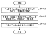
- FIG. 96 is a flowchart of the encoding process of the prediction mode information according to the eleventh embodiment.
- FIG. 97 is a flowchart of the prediction mode information decoding process according to the eleventh embodiment.
- FIG. 98 is a flowchart of the encoding process according to the eleventh embodiment.
- FIG. 99 is a flowchart of the attribute information encoding process according to the eleventh embodiment.
- FIG. 100 is a flowchart of the decoding process according to the eleventh embodiment.
- FIG. 101 is a flowchart of the attribute information decoding process according to the eleventh embodiment.
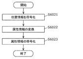
- FIG. 102 is a flowchart of the encoding process according to the eleventh embodiment.
- FIG. 103 is a flowchart of the decoding process according to the eleventh embodiment.
- a three-dimensional data encoding method divides a plurality of three-dimensional points included in point cloud data into processing units each including one or more three-dimensional points, and includes the processing unit as a processing target.
- a bitstream is generated by encoding the attribute information of the three-dimensional point to be processed with reference to the encoded processing unit.
- the processing amount can be reduced.
- multiple 3D points included in the same processing unit can be processed in parallel.
- another processed three-dimensional point included in the processing target processing unit may be referred to.
- coding efficiency can be improved by allowing reference to other 3D points included in the same processing unit.
- a plurality of three-dimensional points included in each processing unit may be encoded using the same prediction mode, and information indicating the prediction mode used for encoding each processing unit may be added to the bitstream. ..
- the processing amount can be reduced by setting the prediction mode for each processing unit. Further, the data amount can be reduced as compared with the case where information indicating the prediction mode for each three-dimensional point is added to the bitstream.
- the prediction used for encoding the processing unit of the processing target The information indicating the mode is not added to the bit stream, the difference between the plurality of referenceable attribute information is greater than the predetermined value, and the number of usable prediction modes is greater than 1.
- the information indicating the prediction mode used for encoding the processing unit to be processed may be added to the bitstream.
- the data amount of the bit stream can be reduced.
- the bitstream may include information indicating the number of three-dimensional points included in the processing unit.
- a three-dimensional data decoding method In a three-dimensional data decoding method according to an aspect of the present disclosure, a plurality of three-dimensional points included in point cloud data is divided from a bitstream, and a processing unit each including one or more three-dimensional points is encoded.
- the encoded data is acquired, and the attribute information of the processing target three-dimensional point included in the processing unit of the processing target is decoded from the encoded data by referring to the decoded processing unit.
- the processing amount can be reduced.
- multiple 3D points included in the same processing unit can be processed in parallel.
- another processed three-dimensional point included in the processing target processing unit may be referred to.
- coding efficiency can be improved by allowing reference to other 3D points included in the same processing unit.
- the bitstream includes information indicating a prediction mode used for encoding each processing unit, and based on the information, decodes a plurality of 3D points included in each processing unit using the same prediction mode. You may.
- the processing amount can be reduced by setting the prediction mode for each processing unit. Further, the data amount can be reduced as compared with the case where information indicating the prediction mode for each three-dimensional point is added to the bitstream.
- a plurality of prediction modes are used.
- a predetermined prediction mode may be used to decode the attribute information of the three-dimensional point to be processed.
- the data amount of the bit stream can be reduced.
- the bitstream may include information indicating the number of three-dimensional points included in the processing unit.
- a three-dimensional data encoding device includes a processor and a memory, and the processor uses the memory to set a plurality of three-dimensional points included in the point cloud data to one each. Generates a bitstream by dividing the processing unit including the above 3D points and encoding the attribute information of the processing target 3D point included in the processing unit of the processing target with reference to the encoded processing unit. To do.
- the processing amount can be reduced.
- a three-dimensional data decoding device includes a processor and a memory, and the processor uses the memory to detect a plurality of three-dimensional points included in point cloud data from a bitstream. Obtained is encoded data in which processing units each of which is divided and each of which includes one or more three-dimensional points are obtained, and from the encoded data, attribute information of the three-dimensional points to be processed included in the processing unit to be processed Is decoded by referring to the already-processed processing unit.
- the processing amount can be reduced.
- a recording medium such as a system, a method, an integrated circuit, a computer program or a computer-readable CD-ROM, and the system, the method, the integrated circuit, and the computer program. And any combination of recording media.
- FIG. 1 is a diagram showing a structure of encoded three-dimensional data according to the present embodiment.
- the three-dimensional space is divided into spaces (SPC) corresponding to pictures in moving image coding, and three-dimensional data is coded in units of spaces.
- the space is further divided into volumes (VLM) corresponding to macroblocks in moving image coding, and prediction and conversion are performed in units of VLM.
- the volume includes a plurality of voxels (VXL) that are the minimum units with which the position coordinates are associated.
- VXL voxels
- the prediction is similar to the prediction performed on a two-dimensional image, and refers to another processing unit to generate predicted three-dimensional data similar to the processing unit of the processing target, and the predicted three-dimensional data and the processing target. It is to encode the difference from the processing unit. Further, this prediction includes not only spatial prediction that refers to other prediction units at the same time but also temporal prediction that refers to prediction units at different times.
- a three-dimensional data encoding device (hereinafter, also referred to as an encoding device) encodes a three-dimensional space represented by point cloud data such as a point cloud
- the three-dimensional data encoding device determines the point cloud according to the voxel size. , Or a plurality of points included in the voxel are collectively encoded.
- the three-dimensional shape of the point cloud can be expressed with high accuracy, and by increasing the size of the voxel, the three-dimensional shape of the point cloud can be roughly expressed.
- the three-dimensional data is a point cloud
- the three-dimensional data is not limited to the point cloud and may be any type of three-dimensional data.
- hierarchical voxels may be used.
- n-th layer it may be indicated in order whether or not the sample points are present in the n-1th layer or lower (lower layer of the n-th layer).
- the sample points in the n-1 or lower layers, it can be considered that the sample point exists at the center of the voxel of the n-th layer and decoding can be performed.
- the encoding device acquires the point cloud data using a distance sensor, a stereo camera, a monocular camera, a gyro, an inertial sensor, or the like.
- Space can be independently decoded intra space (I-SPC), unidirectional reference-only predictive space (P-SPC), and bi-directional reference, similar to moving picture encoding. Classified into any of at least three prediction structures including a bidirectional space (B-SPC).
- the space has two types of time information, that is, the decoding time and the display time.
- GOS Group Of Space
- WLD world
- the spatial area occupied by the world is associated with the absolute position on the earth by GPS or latitude and longitude information. This position information is stored as meta information.
- the meta information may be included in the encoded data or may be transmitted separately from the encoded data.
- all SPCs may be three-dimensionally adjacent to each other, or SPCs that are not three-dimensionally adjacent to other SPCs may exist.
- the processing such as encoding, decoding, or reference to the three-dimensional data included in the processing unit such as GOS, SPC, or VLM is also referred to as simply encoding, decoding, or referencing the processing unit.
- the three-dimensional data included in the processing unit includes, for example, at least one set of a spatial position such as three-dimensional coordinates and a characteristic value such as color information.
- a plurality of SPCs in the same GOS or a plurality of VLMs in the same SPC occupy different spaces but have the same time information (decoding time and display time).
- the SPC that is the first in the decoding order in GOS is I-SPC.
- GOS There are two types of GOS, closed GOS and open GOS.
- the closed GOS is a GOS capable of decoding all SPCs in the GOS when starting decoding from the first I-SPC.
- the open GOS some SPCs whose display time is earlier than the start I-SPC in the GOS refer to different GOSs, and the decryption cannot be performed only by the GOSs.
- the WLD may be decoded from the reverse direction of the encoding order, and if there is a dependency between GOS, reverse reproduction is difficult. Therefore, in such a case, the closed GOS is basically used.
- GOS has a layer structure in the height direction, and encoding or decoding is performed in order from the SPC of the lower layer.
- FIG. 2 is a diagram showing an example of a prediction structure between SPCs belonging to the lowest layer of GOS.
- FIG. 3 is a diagram showing an example of a prediction structure between layers.
- I-SPC there is at least one I-SPC in GOS.
- Objects such as humans, animals, cars, bicycles, traffic lights, or buildings serving as landmarks are present in the three-dimensional space, and it is effective to code particularly small objects as I-SPC.
- the three-dimensional data decoding device (hereinafter, also referred to as a decoding device) decodes only the I-SPC in the GOS when decoding the GOS with a low processing amount or at a high speed.
- the encoding device may switch the encoding interval or appearance frequency of the I-SPC according to the density of the objects in the WLD.
- the encoding device or the decoding device encodes or decodes a plurality of layers in order from the lower layer (layer 1). As a result, it is possible to raise the priority of data near the ground, which has a larger amount of information for an autonomous vehicle, for example.
- the encoded data used in a drone or the like may be encoded or decoded in the GOS in order from the SPC of the upper layer in the height direction.
- the encoding device or the decoding device may encode or decode multiple layers so that the decoding device can roughly grasp the GOS and gradually increase the resolution.
- the encoding device or the decoding device may perform encoding or decoding in the order of layers 3, 8, 1, 9 ...
- static objects or scenes such as buildings or roads (collectively called static objects) and dynamic objects such as cars or people (hereinafter called dynamic objects).
- dynamic objects such as cars or people
- the detection of the object is performed separately by extracting feature points from the data of the point cloud, camera images of a stereo camera, or the like.
- an example of the encoding method of the dynamic object will be described.
- the first method is a method of encoding without distinguishing between static objects and dynamic objects.
- the second method is a method of distinguishing a static object and a dynamic object by identification information.
- GOS is used as an identification unit.
- the GOS including the SPC forming the static object and the GOS including the SPC forming the dynamic object are distinguished by the identification information stored in the encoded data or separately from the encoded data.
- SPC may be used as an identification unit.
- the SPC including the VLM forming the static object and the SPC including the VLM forming the dynamic object are distinguished by the identification information.
- VLM or VXL may be used as an identification unit.
- the VLM or VXL including the static object and the VLM or VXL including the dynamic object are distinguished by the identification information.
- the encoding device may encode the dynamic object as one or more VLMs or SPCs, and encode the VLM or SPC including the static object and the SPC including the dynamic object as different GOSs. Also, the encoding device separately stores the size of the GOS as meta information when the size of the GOS is variable according to the size of the dynamic object.
- the encoding device may encode the static object and the dynamic object independently of each other, and superimpose the dynamic object on the world composed of the static objects.
- the dynamic object is composed of one or more SPCs, and each SPC is associated with one or more SPCs composing a static object on which the SPC is superimposed.
- the dynamic object may be represented by one or more VLMs or VXLs instead of SPC.
- the encoding device may encode the static object and the dynamic object as different streams from each other.
- the encoding device may generate a GOS including one or more SPCs forming a dynamic object. Furthermore, the encoding device may set the GOS (GOS_M) including the dynamic object and the GOS of the static object corresponding to the spatial area of GOS_M to the same size (occupying the same spatial area). As a result, the superimposition processing can be performed in GOS units.
- the P-SPC or B-SPC that constitutes the dynamic object may refer to the SPC included in different encoded GOS.
- the position of a dynamic object changes with time and the same dynamic object is encoded as GOS at different times
- reference across GOS is effective from the viewpoint of compression rate.
- the above first method and second method may be switched depending on the use of the encoded data. For example, when using encoded three-dimensional data as a map, it is desirable to be able to separate dynamic objects, so the encoding device uses the second method. On the other hand, the encoding device uses the first method when encoding three-dimensional data of an event such as a concert or a sports, when it is not necessary to separate the dynamic objects.
- the decoding time and display time of GOS or SPC can be stored in the encoded data or as meta information. Moreover, the time information of all static objects may be the same. At this time, the actual decoding time and display time may be determined by the decoding device. Alternatively, a different value may be given to each GOS or SPC as the decoding time, and the same value may be given to all the display times. Furthermore, like the decoder model in moving picture encoding such as HEVC's HRD (Hypothetical Reference Decoder), the decoder has a buffer of a predetermined size, and if the bitstream is read at a predetermined bit rate according to the decoding time, it can be decoded without failure. A model that guarantees
- GOS in the world Coordinates in a three-dimensional space in the world are represented by three coordinate axes (x axis, y axis, z axis) that are orthogonal to each other.
- GOS in the xz plane is continuously encoded.
- the value of the y-axis is updated after the coding of all the GOS in a certain xz plane is completed. That is, as the encoding progresses, the world extends in the y-axis direction.
- the GOS index number is set in the encoding order.
- the 3D space of the world is associated with GPS or geographical absolute coordinates such as latitude and longitude in a one-to-one correspondence.
- the three-dimensional space may be represented by a relative position from a preset reference position.
- the x-axis, y-axis, and z-axis directions of the three-dimensional space are expressed as a direction vector determined based on latitude and longitude, and the direction vector is stored as meta information together with encoded data.
- the size of GOS is fixed, and the encoding device stores the size as meta information. Further, the size of the GOS may be switched according to whether or not it is an urban area, whether it is indoor or outdoor, or the like. That is, the size of the GOS may be switched according to the amount or nature of the objects that are valuable as information.
- the encoding device may adaptively switch the GOS size or the I-SPC interval in the GOS according to the density of objects in the same world. For example, the encoder reduces the size of GOS and shortens the interval of I-SPC in GOS as the density of objects increases.
- the GOS is subdivided in order to realize random access with a fine granularity.
- the 7th to 10th GOS exist on the back side of the 3rd to 6th GOS, respectively.
- FIG. 6 is a block diagram of three-dimensional data encoding apparatus 100 according to the present embodiment.
- FIG. 7 is a flowchart showing an operation example of the three-dimensional data encoding device 100.
- the three-dimensional data encoding device 100 shown in FIG. 6 generates encoded three-dimensional data 112 by encoding the three-dimensional data 111.
- the three-dimensional data encoding device 100 includes an acquisition unit 101, an encoding area determination unit 102, a division unit 103, and an encoding unit 104.
- the acquisition unit 101 acquires the three-dimensional data 111 that is point cloud data (S101).
- the coding area determination unit 102 determines a coding target area in the spatial area corresponding to the acquired point cloud data (S102). For example, the coding area determination unit 102 determines, according to the position of the user or the vehicle, a spatial area around the position as a coding target area.
- the dividing unit 103 divides the point cloud data included in the area to be encoded into each processing unit.
- the processing unit is the above-mentioned GOS, SPC, or the like.
- the area to be encoded corresponds to, for example, the above-mentioned world.
- the dividing unit 103 divides the point cloud data into processing units based on the size of the GOS set in advance, or the presence or absence of the dynamic object or the size (S103). Further, the dividing unit 103 determines the start position of the SPC that becomes the head in the encoding order in each GOS.
- the encoding unit 104 generates the encoded three-dimensional data 112 by sequentially encoding the plurality of SPCs in each GOS (S104).
- the three-dimensional data encoding device 100 generates the encoded three-dimensional data 112 by encoding the three-dimensional data 111.
- the three-dimensional data encoding device 100 divides the three-dimensional data into first processing units (GOS), which are random access units and are associated with three-dimensional coordinates, respectively.
- the processing unit (GOS) is divided into a plurality of second processing units (SPC), and the second processing unit (SPC) is divided into a plurality of third processing units (VLM).
- the third processing unit (VLM) includes one or more voxels (VXL) that is the minimum unit with which the position information is associated.
- the three-dimensional data encoding device 100 generates encoded three-dimensional data 112 by encoding each of the plurality of first processing units (GOS). Specifically, the three-dimensional data encoding device 100 encodes each of the plurality of second processing units (SPC) in each first processing unit (GOS). In addition, the three-dimensional data encoding device 100 encodes each of the plurality of third processing units (VLM) in each second processing unit (SPC).
- GOS first processing unit
- VLM third processing units
- the three-dimensional data encoding device 100 is the second processing unit to be processed included in the first processing unit (GOS) to be processed.
- SPC is encoded with reference to another second processing unit (SPC) included in the first processing unit (GOS) to be processed. That is, the three-dimensional data encoding apparatus 100 does not refer to the second processing unit (SPC) included in the first processing unit (GOS) different from the first processing unit (GOS) to be processed.
- the second processing unit (SPC) to be processed included in the first processing unit (GOS) to be processed is the first processing unit to be processed.
- Another second processing unit (SPC) included in one processing unit (GOS), or a second processing unit (SPC) included in a first processing unit (GOS) different from the first processing unit (GOS) to be processed ) Is referred to and encoded.
- the three-dimensional data encoding apparatus 100 uses the first type (I-SPC) that does not refer to the other second processing unit (SPC) as the type of the second processing unit (SPC) to be processed, and the other one.
- a second type (P-SPC) that refers to the second processing unit (SPC) or a third type that refers to the other two second processing units (SPC) is selected, and processing is performed according to the selected type.
- FIG. 8 is a block diagram of blocks of the three-dimensional data decoding device 200 according to this embodiment.
- FIG. 9 is a flowchart showing an operation example of the three-dimensional data decoding device 200.
- the three-dimensional data decoding device 200 shown in FIG. 8 decodes the encoded three-dimensional data 211 to generate the decoded three-dimensional data 212.
- the encoded three-dimensional data 211 is, for example, the encoded three-dimensional data 112 generated by the three-dimensional data encoding device 100.
- the three-dimensional data decoding device 200 includes an acquisition unit 201, a decoding start GOS determination unit 202, a decoding SPC determination unit 203, and a decoding unit 204.
- the acquisition unit 201 acquires the encoded three-dimensional data 211 (S201).
- the decoding start GOS determination unit 202 determines the GOS to be decoded (S202). Specifically, the decoding start GOS determination unit 202 refers to the meta information stored in the encoded three-dimensional data 211 or separately from the encoded three-dimensional data, and refers to the spatial position to start the decoding, the object, or , GOS including the SPC corresponding to the time is determined as the GOS to be decoded.
- the decryption SPC determination unit 203 determines the type (I, P, B) of the SPC to be decrypted within GOS (S203). For example, the decoding SPC determining unit 203 determines (1) decoding only I-SPC, (2) decoding I-SPC and P-SPC, or (3) decoding all types. If the type of SPC to be decoded is determined in advance, such as decoding all SPCs, this step may not be performed.
- the decoding unit 204 acquires the address position where the first SPC in the decoding order (same as the encoding order) in the GOS starts in the encoded three-dimensional data 211, and the code of the first SPC is obtained from the address position.
- the encoded data is acquired, and each SPC is sequentially decoded from the head SPC (S204).
- the address position is stored in the meta information or the like.
- the three-dimensional data decoding device 200 decodes the decoded three-dimensional data 212. Specifically, the three-dimensional data decoding device 200 decodes each of the encoded three-dimensional data 211 of the first processing unit (GOS), which is a random access unit and is associated with three-dimensional coordinates. As a result, the decoded three-dimensional data 212 of the first processing unit (GOS) is generated. More specifically, the three-dimensional data decoding device 200 decodes each of the plurality of second processing units (SPC) in each first processing unit (GOS). Also, the three-dimensional data decoding device 200 decodes each of the plurality of third processing units (VLM) in each second processing unit (SPC).
- SPC second processing units
- VLM third processing units
- This meta information is generated by the three-dimensional data encoding device 100 and is included in the encoded three-dimensional data 112 (211).
- FIG. 10 is a diagram showing an example of a table included in the meta information. Note that not all the tables shown in FIG. 10 need to be used, and at least one table may be used.
- the address may be an address in a logical format or a physical address of HDD or memory. Further, instead of the address, information specifying the file segment may be used. For example, a file segment is a unit obtained by segmenting one or more GOS and the like.
- the object-GOS table may indicate multiple GOSs to which the object belongs. If the plurality of GOSs are closed GOSs, the encoding device and the decoding device can perform encoding or decoding in parallel. On the other hand, if the plurality of GOSs are open GOSs, the plurality of GOSs can refer to each other to further improve the compression efficiency.
- the three-dimensional data encoding device 100 extracts a characteristic point unique to an object from a three-dimensional point cloud or the like when encoding the world, detects the object based on the characteristic point, and detects the detected object as a random access point. Can be set as
- the three-dimensional data encoding device 100 includes the first information indicating the plurality of first processing units (GOS) and the three-dimensional coordinates associated with each of the plurality of first processing units (GOS). To generate.
- the encoded three-dimensional data 112 (211) includes this first information.
- the first information further indicates at least one of an object, a time, and a data storage destination, which is associated with each of the plurality of first processing units (GOS).
- the three-dimensional data decoding device 200 acquires the first information from the encoded three-dimensional data 211, and uses the first information to encode the encoded tertiary of the first processing unit corresponding to the designated three-dimensional coordinate, object, or time.
- the original data 211 is specified and the encoded three-dimensional data 211 is decoded.
- the three-dimensional data encoding device 100 may generate and store the following meta information. Further, the three-dimensional data decoding device 200 may use this meta information at the time of decoding.
- a profile may be defined according to the application, and information indicating the profile may be included in the meta information. For example, a profile for an urban area, a suburb, or a flying object is defined, and the maximum or minimum size of the world, SPC, or VLM is defined in each profile. For example, for a city area, more detailed information is required than for a suburban area, so the minimum size of the VLM is set to be small.
- -Meta information may include a tag value indicating the type of object.
- This tag value is associated with the VLM, SPC, or GOS forming the object. For example, the tag value “0” indicates “person”, the tag value “1” indicates “car”, the tag value “2” indicates “traffic light”, etc.
- the tag value is set for each type of object. Good.
- a tag value indicating the size or a property such as a dynamic object or a static object may be used.
- the meta information may include information indicating the range of the spatial area occupied by the world.
- the meta information may store the size of the SPC or VXL as the header information common to the entire stream of encoded data or a plurality of SPCs such as the SPC in GOS.
- the meta information may include identification information of a distance sensor or a camera used for generating the point cloud, or information indicating the position accuracy of the point cloud in the point cloud.
- the meta information may include information indicating whether the world is composed of only static objects or dynamic objects.
- the encoding device or the decoding device may encode or decode two or more different SPCs or GOSs in parallel.
- the GOS to be encoded or decoded in parallel can be determined based on the meta information indicating the spatial position of the GOS.
- the encoding device or the decoding device uses GPS, route information, zoom magnification, or the like.
- the GOS or SPC included in the space specified based on the above may be encoded or decoded.
- the decryption device may perform decryption in order from the space near the self position or the travel route.
- the encoding device or the decoding device may encode or decode the space far from the self position or the travel route by lowering the priority compared to the near space.
- lowering the priority means lowering the processing order, lowering the resolution (processing by thinning out), or lowering the image quality (increasing the coding efficiency, for example, increasing the quantization step).
- the decoding device may only decode the lower layers.
- the decoding device may preferentially decode from a lower hierarchy according to the zoom ratio of the map or the application.
- the encoding device or the decoding device reduces the resolution except for the area within a specific height from the road surface (the area where recognition is performed). It may be encrypted or decrypted.
- the encoding device may individually encode the point clouds that represent the spatial shapes of the indoor and outdoor spaces. For example, by separating GOS that represents an indoor space (indoor GOS) and GOS that represents an outdoor space (outdoor GOS), the decoding device selects the GOS to be decoded according to the viewpoint position when using the encoded data. it can.
- the encoding device may encode the indoor GOS and the outdoor GOS whose coordinates are close to each other so that they are adjacent to each other in the encoded stream. For example, the encoding device associates the two identifiers and stores information indicating the associated identifier in the encoded stream or in the separately stored meta information. Thereby, the decoding device can identify the indoor GOS and the outdoor GOS whose coordinates are close to each other by referring to the information in the meta information.
- the encoding device may switch the size of GOS or SPC between indoor GOS and outdoor GOS. For example, the encoding device sets the size of GOS smaller indoors than outdoors. In addition, the encoding device may change the accuracy when extracting feature points from the point cloud, the accuracy of object detection, or the like between the indoor GOS and the outdoor GOS.
- the encoding device may add information for the decoding device to display the dynamic object separately from the static object, to the encoded data. Accordingly, the decoding device can display the dynamic object and the red frame or the descriptive character together. The decoding device may display only the red frame or the descriptive character instead of the dynamic object. Further, the decryption device may display a finer object type. For example, a red frame may be used for cars and a yellow frame may be used for humans.
- the encoding device or the decoding device encodes the dynamic object and the static object as different SPCs or GOSs according to the appearance frequency of the dynamic object, the ratio of the static object to the dynamic object, or the like. Alternatively, it may be determined whether to decrypt. For example, when the appearance frequency or ratio of dynamic objects exceeds a threshold value, SPC or GOS in which dynamic objects and static objects are mixed is allowed, and the appearance frequency or ratio of dynamic objects does not exceed the threshold value. Does not allow SPC or GOS in which dynamic objects and static objects are mixed.
- the encoding device When detecting the dynamic object from the two-dimensional image information of the camera instead of the point cloud, the encoding device separately acquires information (frame or character) for identifying the detection result and the object position, These pieces of information may be encoded as a part of three-dimensional encoded data. In this case, the decoding device superimposes and displays the auxiliary information (frame or character) indicating the dynamic object on the decoding result of the static object.
- the encoding device may change the coarseness or fineness of VXL or VLM in the SPC according to the complexity of the shape of the static object. For example, the encoding device sets VXL or VLM more densely as the shape of the static object is more complicated. Further, the encoding device may determine the quantization step or the like when quantizing the spatial position or the color information according to the coarseness or fineness of VXL or VLM. For example, the encoder sets a smaller quantization step as VXL or VLM is denser.
- the encoding device or the decoding device performs space encoding or decoding in space units having coordinate information.
- the encoding device and the decoding device perform encoding or decoding on a volume-by-volume basis within the space.
- the volume includes a voxel which is the minimum unit with which the position information is associated.
- the encoding device and the decoding device associate any element with a table that associates each element of spatial information including coordinates, objects, and time with a GOP, or a table that associates each element. Encoding or decoding is performed. Further, the decoding device determines the coordinates using the values of the selected elements, specifies the volume, voxel, or space from the coordinates, and decodes the space including the volume or voxel, or the specified space.
- the encoding device determines a volume, voxel or space that can be selected by an element by extracting feature points or object recognition, and encodes as a randomly accessible volume, voxel or space.
- the space refers to an I-SPC that can be encoded or decoded by the space itself, a P-SPC that is encoded or decoded by referring to any one processed space, and any two processed spaces. It is classified into three types of B-SPC that is encoded or decoded by
- 1 or more volumes correspond to static objects or dynamic objects.
- the space including the static object and the space including the dynamic object are encoded or decoded as GOS different from each other. That is, the SPC including the static object and the SPC including the dynamic object are assigned to different GOSs.
- -Dynamic objects are encoded or decoded for each object and are associated with one or more spaces including static objects. That is, the plurality of dynamic objects are encoded individually, and the obtained encoded data of the plurality of dynamic objects is associated with the SPC including the static object.
- the encoding device and the decoding device raise the priority of I-SPC in GOS and perform encoding or decoding. For example, the encoding device performs encoding so that deterioration of I-SPC is reduced (so that the original three-dimensional data can be more faithfully reproduced after decoding). Further, the decoding device, for example, decodes only I-SPC.
- the encoding device may perform encoding by changing the frequency of using the I-SPC according to the density or the number (quantity) of objects in the world. That is, the encoding device changes the frequency of selecting the I-SPC according to the number or density of the objects included in the three-dimensional data. For example, the encoding device uses the I space more frequently as the objects in the world are denser.
- the encoding device sets a random access point in units of GOS and stores information indicating a spatial area corresponding to GOS in header information.
- the encoding device uses, for example, a default value as the GOS space size.
- the encoding device may change the size of the GOS according to the number (amount) or density of objects or dynamic objects. For example, the encoder reduces the GOS space size as the number of objects or dynamic objects increases, or as the number of objects increases.
- the space or volume includes a feature point group derived using information obtained by a sensor such as a depth sensor, a gyro, or a camera.
- the coordinates of the feature points are set at the center position of the voxel. Further, it is possible to realize high accuracy of the position information by subdividing the voxels.
- the feature point group is derived using multiple pictures.
- the plurality of pictures have at least two types of time information, that is, the actual time information and the same time information (for example, encoding time used for rate control or the like) in the plurality of pictures associated with spaces.
- encoding or decoding is performed in GOS units including one or more spaces.
- the encoding device and the decoding device refer to the space in the processed GOS and predict the P space or B space in the processing target GOS.
- the encoding device and the decoding device do not refer to different GOSs, but use the processed space in the processing target GOS to predict the P space or B space in the processing target GOS.
- the encoding device and the decoding device transmit or receive the encoded stream in world units including one or more GOS.
- GOS has a layer structure in at least one direction within the world, and the encoding device and the decoding device perform encoding or decoding from the lower layer.
- randomly accessible GOS belongs to the lowest layer.
- the GOS belonging to the upper layer refers to the GOS belonging to the same layer and below. That is, GOS is spatially divided in a predetermined direction and includes a plurality of layers each including one or more SPCs.
- the encoding device and the decoding device encode or decode each SPC by referring to the SPC included in the same layer as the SPC or a layer lower than the SPC.
- the encoding device and the decoding device continuously encode or decode the GOS within the world unit including a plurality of GOSs.
- the encoding device and the decoding device write or read information indicating the order (direction) of encoding or decoding as metadata. That is, the encoded data includes information indicating the encoding order of a plurality of GOS.
- the encoding device and the decoding device encode or decode in parallel two or more spaces or GOS different from each other.
- the encoding device and the decoding device encode or decode the space or space information (coordinates, size, etc.) of the GOS.
- the encoding device and the decoding device encode or decode a space or GOS included in a specific space specified based on external information related to its own position or / and area size such as GPS, route information, or magnification. .
- the encoding device or the decoding device encodes or decodes the space far from its own position by lowering the priority compared to the near space.
- the encoding device sets one direction of the world according to the magnification or the use, and encodes GOS having a layer structure in that direction. Further, the decoding device preferentially decodes the GOS having a layer structure in one direction of the world set according to the magnification or the use from the lower layer.
- the encoding device changes the feature point extraction contained in the space, the accuracy of object recognition, the space area size, etc., indoors and outdoors.
- the encoding device and the decoding device encode or decode the indoor GOS and the outdoor GOS, which have close coordinates, adjacently in the world, and also code or decode them in association with each other.
- the three-dimensional data encoding method and the three-dimensional data encoding device for providing a function of transmitting and receiving only necessary information according to the application in the three-dimensional point cloud encoded data A three-dimensional data decoding method and a three-dimensional data decoding device for decoding encoded data will be described.
- Voxels (VXL) that have a certain amount of features are defined as feature voxels (FVXL), and the world (WLD) configured by FVXL is defined as sparse world (SWLD).
- FIG. 11 is a diagram showing a configuration example of the sparse world and the world.
- SWLD includes FGOS which is a GOS configured by FVXL, FSPC which is an SPC configured by FVXL, and FVLM which is a VLM configured by FVXL.
- the data structure and prediction structure of FGOS, FSPC, and FVLM may be the same as GOS, SPC, and VLM.
- the feature amount is a feature amount that expresses VXL three-dimensional position information or visible light information of the VXL position, and is particularly a feature amount that is often detected at the corners and edges of a three-dimensional object.
- the feature amount is a three-dimensional feature amount or a visible light feature amount as described below, but what is the other feature amount indicating the VXL position, brightness, color information, or the like? Anything is fine.
- a SHOT feature amount Signature of Histograms of Orientations
- a PFH feature amount Point Feature Histograms
- a PPF feature amount Point Pair Feature
- the SHOT feature is obtained by dividing the VXL periphery, calculating the inner product of the reference point and the normal vector of the divided area, and creating a histogram.
- This SHOT feature amount has a feature that the dimension number is high and the feature expressing power is high.
- PFH features are obtained by selecting a large number of 2-point pairs near VXL, calculating the normal vector, etc. from the 2 points, and creating a histogram. Since the PFH feature amount is a histogram feature, it has robustness against some disturbance and has a high feature expressing power.
- the PPF feature amount is a feature amount calculated using a normal vector for each of the two VXLs. Since all VXLs are used for this PPF feature amount, it has robustness to occlusion.
- SIFT Scale-Invariant Feature Transform
- SURF Speeded Up Robust Features
- HOG Histogram of Oriented
- SWLD is generated by calculating the above feature amount from each VXL of WLD and extracting FVXL.
- the SWLD may be updated every time the WLD is updated, or may be periodically updated after the elapse of a certain time regardless of the update timing of the WLD.
- SWLD may be generated for each feature amount. For example, different SWLDs may be generated for each feature amount, such as SWLD1 based on the SHOT feature amount and SWLD2 based on the SIFT feature amount, and the SWLD may be selectively used according to the application. Further, the calculated feature amount of each FVXL may be held in each FVXL as feature amount information.
- SWLD Sparse World
- SWLD information instead of WLD
- WLD the read time from the hard disk and the bandwidth and transfer time during network transfer.
- WLD and SWLD in the server as map information and switching the map information to be transmitted to WLD or SWLD in response to a request from the client, the network band and transfer time can be suppressed.
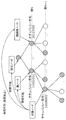
- FIG. 12 and 13 are diagrams showing examples of using SWLD and WLD.
- the client 1 which is an in-vehicle device, requires map information for self-position determination
- the client 1 sends a request for acquisition of map data for self-position estimation to the server (S301).
- the server transmits SWLD to the client 1 in response to the acquisition request (S302).
- the client 1 uses the received SWLD to determine its own position (S303).
- the client 1 obtains the VXL information around the client 1 by various methods such as a range sensor such as a range finder, a stereo camera, or a combination of a plurality of monocular cameras, and uses the obtained VXL information and SWLD to identify itself.
- Estimate location information includes the three-dimensional position information and the orientation of the client 1.
- the client 2 which is an in-vehicle device needs map information as a purpose of drawing a map such as a three-dimensional map
- the client 2 sends a request to acquire map data for map drawing to the server (S311). ).
- the server transmits the WLD to the client 2 according to the acquisition request (S312).
- the client 2 draws a map using the received WLD (S313).
- the client 2 creates a rendering image using, for example, the image captured by the visible light camera or the like by itself and the WLD acquired from the server, and draws the created image on the screen of a car navigation system or the like.
- the server sends the SWLD to the client in the application mainly requiring the feature amount of each VXL such as the self-position estimation, and the WLD in the case where the detailed VXL information is required like the map drawing. Send to client. As a result, map data can be efficiently transmitted and received.
- the client may determine which of SWLD and WLD is necessary, and request the server to send SWLD or WLD. Further, the server may determine which of SWLD and WLD should be transmitted according to the situation of the client or the network.
- SWLD Sparse World
- WWD World
- FIG. 14 is a diagram showing an operation example in this case.
- a low-speed network with a limited network bandwidth such as an LTE (Long Term Evolution) environment
- the client accesses the server via the low-speed network (S321)
- the server maps SWLD is acquired as information (S322).
- a high-speed network with a sufficient network bandwidth such as under Wi-Fi (registered trademark) environment
- the client accesses the server via the high-speed network (S323) and acquires the WLD from the server. Yes (S324). This allows the client to acquire appropriate map information according to the network bandwidth of the client.
- the client receives the SWLD via LTE outdoors, and acquires the WLD via Wi-Fi (registered trademark) when it enters indoors such as a facility. This enables the client to acquire more detailed indoor map information.
- Wi-Fi registered trademark
- the client may request the server for WLD or SWLD depending on the bandwidth of the network used by the client.
- the client may transmit information indicating the bandwidth of the network used by the client to the server, and the server may transmit data (WLD or SWLD) suitable for the client according to the information.
- the server may determine the network bandwidth of the client and transmit data (WLD or SWLD) suitable for the client.
- FIG. 15 is a diagram showing an operation example in this case.
- the client when the client is moving at high speed (S331), the client receives SWLD from the server (S332).
- the client receives the WLD from the server (S334).
- the client can acquire the map information suitable for the speed while suppressing the network band.
- the client can update the rough map information at an appropriate speed by receiving the SWLD having a small amount of data while traveling on the highway.
- the client can acquire more detailed map information by receiving the WLD while traveling on the general road.
- the client may request WLD or SWLD from the server according to the moving speed of the client.
- the client may transmit information indicating the moving speed of the client to the server, and the server may transmit data (WLD or SWLD) suitable for the client according to the information.
- the server may determine the moving speed of the client and transmit data (WLD or SWLD) suitable for the client.
- the client may first acquire SWLD from the server and then acquire the WLD of the important area among them. For example, when the client acquires map data, the client first acquires rough map information by SWLD, narrows down an area where many features such as buildings, signs, and people appear, and extracts the WLD of the narrowed area. Get it later. As a result, the client can acquire detailed information on a necessary area while suppressing the amount of data received from the server.
- the server may create different SWLDs for each object from the WLD, and the client may receive each according to the purpose.
- the network band can be suppressed.
- the server recognizes a person or a vehicle from the WLD in advance and creates a person's SWLD and a vehicle's SWLD.
- the client receives the SWLD of the person when it wants to acquire the information of the people around it, and receives the SWLD of the car when it wants to acquire the information of the car.
- SWLD types may be distinguished by the information (flag or type) added to the header or the like.
- FIG. 16 is a block diagram of three-dimensional data encoding apparatus 400 according to the present embodiment.
- FIG. 17 is a flowchart of the three-dimensional data encoding process by the three-dimensional data encoding device 400.
- the three-dimensional data encoding device 400 shown in FIG. 16 encodes the input three-dimensional data 411 to generate encoded three-dimensional data 413 and 414 which are encoded streams.
- the coded three-dimensional data 413 is coded three-dimensional data corresponding to WLD
- the coded three-dimensional data 414 is coded three-dimensional data corresponding to SWLD.
- the three-dimensional data encoding device 400 includes an acquisition unit 401, an encoding region determination unit 402, a SWLD extraction unit 403, a WLD encoding unit 404, and a SWLD encoding unit 405.
- the acquisition unit 401 acquires input three-dimensional data 411 that is point cloud data in a three-dimensional space (S401).
- the coding area determination unit 402 determines the spatial area to be coded based on the spatial area in which the point cloud data exists (S402).
- the SWLD extraction unit 403 defines the spatial area to be encoded as WLD, and calculates the feature amount from each VXL included in the WLD. Then, the SWLD extraction unit 403 extracts VXL having a feature amount equal to or larger than a predetermined threshold value, defines the extracted VXL as FVXL, and adds the FVXL to SWLD to generate the extracted three-dimensional data 412. (S403). That is, the extracted three-dimensional data 412 whose feature amount is the threshold value or more is extracted from the input three-dimensional data 411.
- the WLD encoding unit 404 generates the encoded three-dimensional data 413 corresponding to the WLD by encoding the input three-dimensional data 411 corresponding to the WLD (S404). At this time, the WLD encoding unit 404 adds information for distinguishing that the encoded three-dimensional data 413 is a stream including the WLD to the header of the encoded three-dimensional data 413.
- the SWLD encoding unit 405 generates encoded three-dimensional data 414 corresponding to SWLD by encoding the extracted three-dimensional data 412 corresponding to SWLD (S405). At this time, the SWLD encoding unit 405 adds information for distinguishing that the encoded three-dimensional data 414 is a stream including SWLD to the header of the encoded three-dimensional data 414.
- the processing order of the process of generating the encoded three-dimensional data 413 and the process of generating the encoded three-dimensional data 414 may be the reverse of the above. Moreover, some or all of these processes may be performed in parallel.
- a parameter “world_type” is defined.
- one of the encoded three-dimensional data 413 and 414 may include a specific flag.
- the encoded three-dimensional data 414 may be provided with a flag including that the stream includes SWLD. In this case, the decoding device can determine whether the stream includes the WLD or the stream including the SWLD depending on the presence / absence of the flag.
- the encoding method used by the WLD encoding unit 404 when encoding the WLD and the encoding method used by the SWLD encoding unit 405 when encoding the SWLD may be different.
- inter prediction may be prioritized among the intra prediction and the inter prediction over the coding method used for WLD.
- the encoding method used for SWLD and the encoding method used for WLD may differ in the method of expressing the three-dimensional position.
- the three-dimensional position of FVXL may be expressed by three-dimensional coordinates
- WLD the three-dimensional position may be expressed by an octree described below, and vice versa.
- the SWLD encoding unit 405 performs encoding so that the data size of the encoded three-dimensional data 414 of SWLD is smaller than the data size of the encoded three-dimensional data 413 of WLD.
- SWLD may have lower correlation between data than WLD.
- the encoding efficiency is reduced, and the data size of the encoded three-dimensional data 414 may be larger than the data size of the encoded three-dimensional data 413 of the WLD. Therefore, when the data size of the obtained encoded three-dimensional data 414 is larger than the data size of the encoded three-dimensional data 413 of the WLD, the SWLD encoding unit 405 re-encodes the data size. To regenerate the encoded three-dimensional data 414.
- the SWLD extraction unit 403 regenerates the extracted three-dimensional data 412 in which the number of feature points to be extracted is reduced, and the SWLD encoding unit 405 encodes the extracted three-dimensional data 412.
- the degree of quantization in the SWLD encoding unit 405 may be made coarser.
- the degree of quantization can be coarsened by rounding the data of the lowest layer.
- the SWLD encoding unit 405 does not generate the SWLD encoded three-dimensional data 414. May be.
- the WLD encoded three-dimensional data 413 may be copied to the SWLD encoded three-dimensional data 414. That is, the encoded three-dimensional data 413 of the WLD may be used as it is as the encoded three-dimensional data 414 of the SWLD.
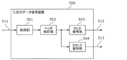
- FIG. 18 is a block diagram of the three-dimensional data decoding device 500 according to this embodiment.
- FIG. 19 is a flowchart of the three-dimensional data decoding process by the three-dimensional data decoding device 500.
- the three-dimensional data decoding device 500 shown in FIG. 18 generates decoded three-dimensional data 512 or 513 by decoding the encoded three-dimensional data 511.
- the encoded three-dimensional data 511 is, for example, the encoded three-dimensional data 413 or 414 generated by the three-dimensional data encoding device 400.
- the three-dimensional data decoding device 500 includes an acquisition unit 501, a header analysis unit 502, a WLD decoding unit 503, and a SWLD decoding unit 504.
- the acquisition unit 501 acquires the encoded three-dimensional data 511 (S501).
- the header analysis unit 502 analyzes the header of the encoded three-dimensional data 511, and determines whether the encoded three-dimensional data 511 is a stream including WLD or a stream including SWLD (S502). For example, the determination is performed by referring to the above-mentioned parameter of world_type.
- the WLD decoding unit 503 When the encoded three-dimensional data 511 is a stream including the WLD (Yes in S503), the WLD decoding unit 503 generates the decoded three-dimensional data 512 of the WLD by decoding the encoded three-dimensional data 511 (S504). . On the other hand, when the encoded three-dimensional data 511 is a stream including SWLD (No in S503), the SWLD decoding unit 504 generates the decoded three-dimensional data 513 of SWLD by decoding the encoded three-dimensional data 511 ( S505).
- the decoding method used when the WLD decoding unit 503 decodes the WLD and the decoding method used when the SWLD decoding unit 504 decodes the SWLD may be different.
- inter prediction may be prioritized among the intra prediction and the inter prediction over the decoding method used for WLD.
- the decoding method used for SWLD and the decoding method used for WLD may differ in the method of expressing the three-dimensional position.
- the three-dimensional position of FVXL may be expressed by three-dimensional coordinates
- WLD the three-dimensional position may be expressed by an octree described below, and vice versa.
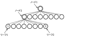
- FIG. 20 is a diagram illustrating an example of VXL of WLD.
- FIG. 21 is a diagram showing an octree tree structure of the WLD shown in FIG.
- the octree structure is composed of nodes and leaves. Each node has a maximum of 8 nodes or leaves. Each leaf has VXL information.
- leaves 1, 2, and 3 represent VXL1, VXL2, and VXL3 shown in FIG. 20, respectively.
- each node and leaf corresponds to a three-dimensional position.
- Node 1 corresponds to the entire block shown in FIG.
- the block corresponding to the node 1 is divided into eight blocks. Of the eight blocks, the block containing the valid VXL is set as the node, and the other blocks are set as the leaves.
- the block corresponding to the node is further divided into eight nodes or leaves, and this process is repeated for each hierarchical level of the tree structure. In addition, all the blocks in the lowest layer are set as leaves.
- FIG. 22 is a diagram showing an example of SWLD generated from the WLD shown in FIG. VXL1 and VXL2 shown in FIG. 20 are determined to be FVXL1 and FVXL2 as a result of feature amount extraction, and are added to SWLD.
- VXL3 is not determined to be FVXL and is not included in SWLD.
- FIG. 23 is a diagram showing an octree tree structure of the SWLD shown in FIG. In the octree structure shown in FIG. 23, the leaf 3 corresponding to VXL3 shown in FIG. 21 is deleted. As a result, the node 3 shown in FIG. 21 has no valid VXL and is changed to a leaf.
- the number of leaves of SWLD is generally smaller than the number of leaves of WLD, and the encoded three-dimensional data of SWLD is smaller than the encoded three-dimensional data of WLD.
- a client such as an in-vehicle device receives SWLD from a server when performing self-position estimation, performs self-position estimation using SWLD, and when performing obstacle detection, a range sensor such as a range finder or a stereo.
- Obstacle detection may be performed based on three-dimensional information of the surroundings acquired by oneself using various methods such as a camera or a combination of a plurality of monocular cameras.
- the server may hold a subsampled world (subWLD) that subsamples the WLD and send SWLD and subWLD to the client for static obstacle detection.
- subWLD subsampled world
- the client side can perform self-position estimation and obstacle detection while suppressing the network band.
- the server may generate a mesh from the WLD and hold it in advance as a mesh world (MWLD). For example, the client receives the MWLD when it needs a rough three-dimensional drawing and the WLD when it needs a detailed three-dimensional drawing. Thereby, the network band can be suppressed.
- MWLD mesh world
- the server sets the VXL of each VXL whose feature amount is equal to or more than the threshold value to the FVXL, but the FVXL may be calculated by a different method. For example, the server determines that VXL, VLM, SPC, or GOS forming a signal or an intersection is necessary for self-position estimation, driving assistance, autonomous driving, or the like, and includes it in SWLD as FVXL, FVLM, FSPC, or FGOS. You may do so. Further, the above determination may be made manually. The FVXL or the like obtained by the above method may be added to the FVXL or the like set based on the feature amount. That is, the SWLD extraction unit 403 may further extract the data corresponding to the object having the predetermined attribute from the input three-dimensional data 411 as the extracted three-dimensional data 412.
- the server may separately hold FVXL necessary for self-position estimation such as traffic lights or intersections, driving assistance, or automatic driving as an upper layer of SWLD (for example, lane world).
- the server may add an attribute to the VXL in the WLD for each random access unit or each predetermined unit.
- the attribute includes, for example, information indicating whether it is necessary or unnecessary for self-position estimation, or information indicating whether it is important as traffic information such as a signal or an intersection. Further, the attribute may include a correspondence relationship with Feature (intersection or road) in the lane information (GDF: Geographic Data Files etc.).
- the following method may be used as a method for updating WLD or SWLD.
- Update information indicating changes in people, construction, or row of trees (for trucks) is uploaded to the server as point clouds or metadata.
- the server updates the WLD based on the upload, and then updates the SWLD using the updated WLD.
- the client may transmit the 3D information generated by itself to the server together with the update notification. Good.
- the server updates SWLD using WLD. If the SWLD is not updated, the server determines that the WLD itself is old.
- header information of the encoded stream information for distinguishing between WLD and SWLD is added, but when there are many kinds of worlds such as mesh world or lane world, they are distinguished.
- the information may be added to the header information.
- information for distinguishing each may be added to the header information.
- the SWLD is composed of FVXL, but it may include VXL that is not determined to be FVXL.
- the SWLD may include an adjacent VXL used when calculating the feature amount of the FVXL. Accordingly, even when the feature amount information is not added to each FVXL of SWLD, the client can calculate the feature amount of FVXL when receiving the SWLD. At that time, the SWLD may include information for distinguishing whether each VXL is FVXL or VXL.
- the three-dimensional data encoding device 400 extracts and extracts the extracted three-dimensional data 412 (second three-dimensional data) whose feature amount is the threshold value or more from the input three-dimensional data 411 (first three-dimensional data).
- the encoded three-dimensional data 412 is encoded to generate encoded three-dimensional data 414 (first encoded three-dimensional data).
- the three-dimensional data encoding device 400 generates the encoded three-dimensional data 414 by encoding the data whose feature amount is equal to or more than the threshold value. As a result, the data amount can be reduced as compared with the case where the input three-dimensional data 411 is directly encoded. Therefore, the three-dimensional data encoding device 400 can reduce the amount of data to be transmitted.
- the three-dimensional data encoding device 400 further encodes the input three-dimensional data 411 to generate encoded three-dimensional data 413 (second encoded three-dimensional data).
- the three-dimensional data encoding device 400 can selectively transmit the encoded three-dimensional data 413 and the encoded three-dimensional data 414 according to the intended use or the like.
- the extracted three-dimensional data 412 is encoded by the first encoding method, and the input three-dimensional data 411 is encoded by the second encoding method different from the first encoding method.
- the three-dimensional data encoding device 400 can use the encoding method suitable for the input three-dimensional data 411 and the extracted three-dimensional data 412, respectively.
- inter prediction is prioritized over intra prediction and inter prediction over the second coding method.
- the three-dimensional data encoding device 400 can increase the priority of inter prediction with respect to the extracted three-dimensional data 412 in which the correlation between adjacent data tends to be low.
- the representation method of the three-dimensional position is different between the first encoding method and the second encoding method.
- a three-dimensional position is represented by an octree
- a three-dimensional position is represented by three-dimensional coordinates.
- the three-dimensional data encoding device 400 can use a more suitable three-dimensional position representation method for three-dimensional data having different data numbers (the number of VXL or FVXL).
- At least one of the encoded three-dimensional data 413 and 414 is the encoded three-dimensional data obtained by encoding the input three-dimensional data 411, or the input three-dimensional data 411. It includes an identifier indicating whether the data is encoded three-dimensional data obtained by encoding a part of the data. That is, the identifier indicates whether the encoded three-dimensional data is the encoded three-dimensional data 413 of the WLD or the encoded three-dimensional data 414 of the SWLD.
- the decoding device can easily determine whether the acquired encoded three-dimensional data is the encoded three-dimensional data 413 or the encoded three-dimensional data 414.
- the three-dimensional data encoding device 400 encodes the extracted three-dimensional data 412 so that the data amount of the encoded three-dimensional data 414 is smaller than the data amount of the encoded three-dimensional data 413.
- the three-dimensional data encoding device 400 can make the data amount of the encoded three-dimensional data 414 smaller than the data amount of the encoded three-dimensional data 413.
- the three-dimensional data encoding device 400 further extracts, from the input three-dimensional data 411, data corresponding to an object having a predetermined attribute as extracted three-dimensional data 412.
- an object having a predetermined attribute is an object necessary for self-position estimation, driving assistance, automatic driving, or the like, such as a signal or an intersection.
- the three-dimensional data encoding device 400 can generate the encoded three-dimensional data 414 including the data required by the decoding device.
- the three-dimensional data encoding device 400 (server) further transmits one of the encoded three-dimensional data 413 and 414 to the client according to the state of the client.
- the three-dimensional data encoding device 400 can transmit appropriate data according to the state of the client.
- the status of the client includes the communication status of the client (for example, network bandwidth) or the moving speed of the client.
- the three-dimensional data encoding device 400 further transmits one of the encoded three-dimensional data 413 and 414 to the client in response to the request from the client.
- the three-dimensional data encoding device 400 can transmit appropriate data according to the request of the client.
- the three-dimensional data decoding device 500 decodes the encoded three-dimensional data 413 or 414 generated by the above three-dimensional data encoding device 400.
- the three-dimensional data decoding device 500 first-decodes the encoded three-dimensional data 414 obtained by encoding the extracted three-dimensional data 412 in which the feature amount extracted from the input three-dimensional data 411 has a threshold value or more. Decrypt by the method. Also, the three-dimensional data decoding device 500 decodes the encoded three-dimensional data 413 obtained by encoding the input three-dimensional data 411 by the second decoding method different from the first decoding method.
- the three-dimensional data decoding device 500 selects the coded three-dimensional data 414 and the coded three-dimensional data 413 obtained by coding the data whose feature amount is equal to or more than the threshold value, for example, according to the intended use. Can be received. Thereby, the three-dimensional data decoding device 500 can reduce the amount of data to be transmitted. Furthermore, the 3D data decoding apparatus 500 can use a decoding method suitable for the input 3D data 411 and the extracted 3D data 412, respectively.
- inter prediction is given priority over intra prediction and inter prediction over the second decoding method.
- the three-dimensional data decoding device 500 can increase the priority of inter prediction for the extracted three-dimensional data in which the correlation between adjacent data is likely to be low.
- the representation method of the three-dimensional position is different between the first decoding method and the second decoding method.
- the three-dimensional position is represented by an octree
- the three-dimensional position is represented by the three-dimensional coordinates.
- the three-dimensional data decoding device 500 can use a more suitable three-dimensional position representation method for three-dimensional data having different data numbers (the number of VXL or FVXL).
- At least one of the encoded three-dimensional data 413 and 414 is the encoded three-dimensional data obtained by encoding the input three-dimensional data 411, or the input three-dimensional data 411. It includes an identifier indicating whether the data is encoded three-dimensional data obtained by encoding a part of the data.
- the three-dimensional data decoding device 500 identifies the encoded three-dimensional data 413 and 414 with reference to the identifier.
- the three-dimensional data decoding device 500 can easily determine whether the acquired encoded three-dimensional data is the encoded three-dimensional data 413 or the encoded three-dimensional data 414.
- the three-dimensional data decoding device 500 further notifies the server of the state of the client (three-dimensional data decoding device 500).
- the three-dimensional data decoding device 500 receives one of the encoded three-dimensional data 413 and 414 transmitted from the server according to the state of the client.
- the three-dimensional data decoding device 500 can receive appropriate data according to the state of the client.
- the status of the client includes the communication status of the client (for example, network bandwidth) or the moving speed of the client.
- the three-dimensional data decoding device 500 further requests one of the encoded three-dimensional data 413 and 414 from the server and, in response to the request, transmits one of the encoded three-dimensional data 413 and 414 transmitted from the server. To receive.
- the three-dimensional data decoding device 500 can receive appropriate data according to the application.
- FIG. 24 is a block diagram of the three-dimensional data creation device 620 according to this embodiment.
- the three-dimensional data creation device 620 is, for example, included in the own vehicle, and by combining the received second three-dimensional data 635 with the first three-dimensional data 632 created by the three-dimensional data creation device 620, a higher density is obtained. 3rd three-dimensional data 636 is created.
- the three-dimensional data creation device 620 includes a three-dimensional data creation unit 621, a request range determination unit 622, a search unit 623, a reception unit 624, a decoding unit 625, and a synthesis unit 626.
- the three-dimensional data creation unit 621 creates the first three-dimensional data 632 using the sensor information 631 detected by the sensor of the vehicle.
- the request range determination unit 622 determines the request range which is the three-dimensional space range in which the data is lacking in the created first three-dimensional data 632.
- the search unit 623 searches for a surrounding vehicle that owns the three-dimensional data of the requested range, and transmits the requested range information 633 indicating the requested range to the surrounding vehicles specified by the search.
- the receiving unit 624 receives the encoded three-dimensional data 634, which is the encoded stream in the requested range, from the surrounding vehicles (S624).
- the search unit 623 may indiscriminately issue a request to all vehicles existing in the specific range and receive the encoded three-dimensional data 634 from the other party who responded.
- the search unit 623 may issue a request to an object such as a traffic light or a sign, and receive the encoded three-dimensional data 634 from the object, not limited to the vehicle.
- the decoding unit 625 acquires the second three-dimensional data 635 by decoding the received encoded three-dimensional data 634.
- the synthesizing unit 626 synthesizes the first three-dimensional data 632 and the second three-dimensional data 635 to create more dense third three-dimensional data 636.
- FIG. 25 is a block diagram of the three-dimensional data transmission device 640.
- the three-dimensional data transmission device 640 is, for example, included in the above-described peripheral vehicle, processes the fifth three-dimensional data 652 created by the peripheral vehicle into the sixth three-dimensional data 654 requested by the own vehicle, and then generates the sixth three-dimensional data.
- the encoded three-dimensional data 634 is generated by encoding 654, and the encoded three-dimensional data 634 is transmitted to the vehicle.
- the three-dimensional data transmitting device 640 includes a three-dimensional data creating unit 641, a receiving unit 642, an extracting unit 643, an encoding unit 644, and a transmitting unit 645.
- the three-dimensional data creating unit 641 creates the fifth three-dimensional data 652 using the sensor information 651 detected by the sensors provided in the surrounding vehicles.
- the receiving unit 642 receives the request range information 633 transmitted from the own vehicle.
- the extraction unit 643 processes the fifth three-dimensional data 652 into the sixth three-dimensional data 654 by extracting the three-dimensional data of the requested range indicated by the requested range information 633 from the fifth three-dimensional data 652. To do.
- the encoding unit 644 encodes the sixth three-dimensional data 654 to generate encoded three-dimensional data 634 that is an encoded stream. Then, the transmission unit 645 transmits the encoded three-dimensional data 634 to the vehicle.
- each vehicle includes the three-dimensional data creation device 620 and the surrounding vehicles include the three-dimensional data transmission device 640.
- each vehicle includes the three-dimensional data creation device 620 and the three-dimensional data transmission device 620. It may have a function with 640.
- the self-position estimation matches a three-dimensional map with three-dimensional information (hereinafter, three-dimensional data detected by the vehicle) around the vehicle acquired by a range finder (LiDAR, etc.) mounted on the vehicle or a sensor such as a stereo camera. Then, it can be realized by estimating the own vehicle position in the three-dimensional map.
- three-dimensional information hereinafter, three-dimensional data detected by the vehicle
- LiDAR range finder
- a sensor such as a stereo camera
- 3D maps are not only 3D point clouds such as HD maps advocated by HERE, but also 2D map data such as road and intersection shape information, or real-time changes such as congestion and accidents. Information to be included may be included.
- a three-dimensional map is composed of a plurality of layers such as three-dimensional data, two-dimensional data, and metadata that changes in real time, and the device can also acquire or refer to only necessary data.
- the point cloud data may be the SWLD described above, or may include point cloud data that is not a feature point.
- the point cloud data is transmitted and received based on one or a plurality of random access units.
- the apparatus compares the shapes of the point clouds in the point clouds with each other, and determines that the portions with high similarity between the feature points are at the same position. Further, when the three-dimensional map is composed of SWLD, the apparatus compares the feature points forming the SWLD with the three-dimensional feature points extracted from the own-vehicle detected three-dimensional data to perform matching.
- (A) the three-dimensional map and the own-vehicle detected three-dimensional data can be acquired, and (B) those accuracies satisfy predetermined criteria. Will be required. However, in the following abnormal cases, (A) or (B) cannot be satisfied.
- FIG. 26 is a block diagram showing a configuration example of the three-dimensional information processing apparatus 700 according to this embodiment.
- the three-dimensional information processing device 700 is mounted on a moving body such as an automobile. As illustrated in FIG. 26, the 3D information processing apparatus 700 includes a 3D map acquisition unit 701, a vehicle detection data acquisition unit 702, an abnormal case determination unit 703, a coping operation determination unit 704, and an operation control unit 705. With.
- the three-dimensional information processing apparatus 700 is not shown for detecting a structure or a moving object around the vehicle, such as a camera for acquiring a two-dimensional image or a sensor for one-dimensional data using ultrasonic waves or lasers.
- a two-dimensional or one-dimensional sensor may be provided.
- the 3D information processing apparatus 700 may include a communication unit (not shown) for acquiring the 3D map by a mobile communication network such as 4G or 5G, or vehicle-to-vehicle communication or road-to-vehicle communication. .
- the three-dimensional map acquisition unit 701 acquires a three-dimensional map 711 near the travel route.
- the three-dimensional map acquisition unit 701 acquires the three-dimensional map 711 by a mobile communication network, vehicle-vehicle communication, or road-vehicle communication.
- the vehicle detection data acquisition unit 702 acquires the vehicle detection three-dimensional data 712 based on the sensor information. For example, the vehicle detection data acquisition unit 702 generates the vehicle detection three-dimensional data 712 based on the sensor information acquired by the sensor included in the vehicle.
- the abnormal case determination unit 703 detects an abnormal case by performing a predetermined check on at least one of the acquired three-dimensional map 711 and the detected vehicle three-dimensional data 712. That is, the abnormal case determination unit 703 determines whether at least one of the acquired three-dimensional map 711 and the acquired vehicle three-dimensional data 712 is abnormal.
- the coping operation determining unit 704 determines a coping operation for the abnormal case.
- the operation control unit 705 controls the operation of each processing unit such as the three-dimensional map acquisition unit 701 that is necessary for performing the coping operation.
- the 3D information processing apparatus 700 ends the process.
- the 3D information processing apparatus 700 also uses the 3D map 711 and the own vehicle detected 3D data 712 to estimate the self position of the vehicle having the 3D information processing apparatus 700. Next, the three-dimensional information processing apparatus 700 uses the result of self-position estimation to automatically drive the vehicle.
- the three-dimensional information processing apparatus 700 acquires the map data (three-dimensional map 711) including the first three-dimensional position information via the communication path.
- the first three-dimensional position information is coded in units of subspaces having three-dimensional coordinate information, each is an aggregate of one or more subspaces, and each of the plurality of random numbers is capable of being independently decoded. Including access unit.
- the first three-dimensional position information is data (SWLD) in which feature points having a three-dimensional feature amount equal to or larger than a predetermined threshold value are encoded.
- the 3D information processing apparatus 700 also generates second 3D position information (self vehicle detection 3D data 712) from the information detected by the sensor. Next, the three-dimensional information processing apparatus 700 performs the abnormality determination processing on the first three-dimensional position information or the second three-dimensional position information to obtain the first three-dimensional position information or the second three-dimensional position information. It is determined whether the three-dimensional position information is abnormal.
- the three-dimensional information processing device 700 determines a coping action for the abnormality. Next, the three-dimensional information processing apparatus 700 carries out the control necessary for carrying out the coping operation.
- the three-dimensional information processing apparatus 700 can detect an abnormality in the first three-dimensional position information or the second three-dimensional position information and take a coping action.
- FIG. 27 is a block diagram showing a configuration example of the three-dimensional data creation device 810 according to the present embodiment.
- the three-dimensional data creation device 810 is installed in, for example, a vehicle.
- the three-dimensional data creation device 810 sends and receives three-dimensional data to and from an external traffic monitoring cloud, a preceding vehicle or a following vehicle, and creates and stores three-dimensional data.
- the three-dimensional data creation device 810 includes a data reception unit 811, a communication unit 812, a reception control unit 813, a format conversion unit 814, a plurality of sensors 815, a three-dimensional data creation unit 816, and a three-dimensional data synthesis unit. 817, a three-dimensional data storage unit 818, a communication unit 819, a transmission control unit 820, a format conversion unit 821, and a data transmission unit 822.
- the data receiving unit 811 receives the three-dimensional data 831 from the traffic monitoring cloud or the preceding vehicle.
- the three-dimensional data 831 includes, for example, information such as a point cloud, a visible light image, depth information, sensor position information, or speed information including a region that cannot be detected by the sensor 815 of the vehicle.
- the communication unit 812 communicates with the traffic monitoring cloud or the preceding vehicle and transmits a data transmission request or the like to the traffic monitoring cloud or the preceding vehicle.
- the reception control unit 813 exchanges information such as a compatible format with the communication destination via the communication unit 812, and establishes communication with the communication destination.
- the format conversion unit 814 generates the three-dimensional data 832 by performing format conversion or the like on the three-dimensional data 831 received by the data receiving unit 811. In addition, the format conversion unit 814 performs decompression or decoding processing when the three-dimensional data 831 is compressed or encoded.
- the plurality of sensors 815 are a sensor group such as LiDAR, a visible light camera or an infrared camera that acquires information outside the vehicle, and generates sensor information 833.
- the sensor 815 is a laser sensor such as LiDAR
- the sensor information 833 is three-dimensional data such as a point cloud (point cloud data). Note that the number of sensors 815 need not be plural.
- the three-dimensional data creation unit 816 generates three-dimensional data 834 from the sensor information 833.
- the three-dimensional data 834 includes information such as a point cloud, visible light image, depth information, sensor position information, or speed information, for example.
- the three-dimensional data synthesizing unit 817 synthesizes the three-dimensional data 832 created by the traffic monitoring cloud or the preceding vehicle with the three-dimensional data 834 created based on the sensor information 833 of the own vehicle, thereby The three-dimensional data 835 including the space in front of the preceding vehicle that cannot be detected by the sensor 815 is constructed.
- the three-dimensional data storage unit 818 stores the generated three-dimensional data 835 and the like.
- the communication unit 819 communicates with the traffic monitoring cloud or the following vehicle and transmits a data transmission request or the like to the traffic monitoring cloud or the following vehicle.
- the transmission control unit 820 exchanges information such as compatible formats with the communication destination via the communication unit 819, and establishes communication with the communication destination. In addition, the transmission control unit 820 determines the space of the three-dimensional data to be transmitted based on the three-dimensional data construction information of the three-dimensional data 832 generated by the three-dimensional data synthesizing unit 817 and the data transmission request from the communication destination. Determine a transmission area.
- the transmission control unit 820 determines a transmission area including a space in front of the own vehicle that cannot be detected by the sensor of the following vehicle in response to a traffic transmission cloud or a data transmission request from the following vehicle. In addition, the transmission control unit 820 determines the transmission area by determining whether or not the transmittable space or the transmitted space is updated based on the three-dimensional data construction information. For example, the transmission control unit 820 determines the area designated by the data transmission request and the area in which the corresponding three-dimensional data 835 exists as the transmission area. Then, the transmission control unit 820 notifies the format conversion unit 821 of the format and the transmission area that the communication destination supports.
- the format conversion unit 821 converts the three-dimensional data 836 in the transmission area out of the three-dimensional data 835 stored in the three-dimensional data storage unit 818 into a format compatible with the receiving side to generate the three-dimensional data 837. To generate.
- the format conversion unit 821 may reduce the data amount by compressing or encoding the three-dimensional data 837.
- the data transmission unit 822 transmits the three-dimensional data 837 to the traffic monitoring cloud or the following vehicle.
- the three-dimensional data 837 includes, for example, information such as a point cloud in front of the own vehicle including a blind spot of the following vehicle, a visible light image, depth information, or sensor position information.
- the three-dimensional data creation device 810 acquires from the outside the three-dimensional data 831 of the area that cannot be detected by the sensor 815 of the own vehicle, and the three-dimensional data 831 and the sensor information 833 detected by the sensor 815 of the own vehicle. And the three-dimensional data 834 based on the above are combined to generate the three-dimensional data 835. As a result, the three-dimensional data creation device 810 can generate three-dimensional data in a range that cannot be detected by the sensor 815 of the vehicle.
- the three-dimensional data creation device 810 in response to a data transmission request from the traffic monitoring cloud or the following vehicle, collects three-dimensional data including the space in front of the own vehicle that cannot be detected by the sensor of the following vehicle from the traffic monitoring cloud or the following vehicle. Can be sent to vehicles, etc.
- a client device such as a vehicle transmits three-dimensional data to another vehicle or a server such as a traffic monitoring cloud.
- the client device transmits the sensor information obtained by the sensor to the server or another client device.
- FIG. 28 is a diagram showing a configuration of a transmission / reception system of the three-dimensional map and the sensor information according to the present embodiment.
- the system includes a server 901 and client devices 902A and 902B.
- client apparatuses 902A and 902B are not particularly distinguished, they are also referred to as the client apparatus 902.
- the client device 902 is, for example, an in-vehicle device mounted on a moving body such as a vehicle.
- the server 901 is, for example, a traffic monitoring cloud or the like, and can communicate with a plurality of client devices 902.
- the server 901 transmits a three-dimensional map composed of a point cloud to the client device 902.
- the configuration of the three-dimensional map is not limited to the point cloud, and may be other three-dimensional data such as a mesh structure.
- the client device 902 transmits the sensor information acquired by the client device 902 to the server 901.
- the sensor information includes, for example, at least one of LiDAR acquisition information, visible light image, infrared image, depth image, sensor position information, and speed information.
- the data transmitted and received between the server 901 and the client device 902 may be compressed for data reduction, or may be left uncompressed to maintain the accuracy of the data.
- a three-dimensional compression method based on an octree structure for example, can be used for the point cloud.
- a two-dimensional image compression method can be used for the visible light image, the infrared image, and the depth image.
- the two-dimensional image compression method is, for example, MPEG-4 AVC or HEVC standardized by MPEG.
- the server 901 transmits the three-dimensional map managed by the server 901 to the client device 902 in response to the transmission request of the three-dimensional map from the client device 902.
- the server 901 may transmit the three-dimensional map without waiting for the transmission request for the three-dimensional map from the client device 902.
- the server 901 may broadcast the three-dimensional map to one or more client devices 902 in a predetermined space.
- the server 901 may transmit a three-dimensional map suitable for the position of the client device 902 to the client device 902 that has once received the transmission request, at regular time intervals.
- the server 901 may also send the three-dimensional map to the client device 902 every time the three-dimensional map managed by the server 901 is updated.
- the client device 902 issues a three-dimensional map transmission request to the server 901. For example, when the client device 902 wants to perform self-position estimation during traveling, the client device 902 transmits a transmission request for a three-dimensional map to the server 901.
- the client device 902 may issue a three-dimensional map transmission request to the server 901 in the following cases.
- the client device 902 may issue a request for transmitting the 3D map to the server 901.
- the client device 902 may issue a request for transmitting the three-dimensional map to the server 901.
- the client device 902 may issue a transmission request for the three-dimensional map to the server 901 at a certain time before the client device 902 leaves the space indicated by the three-dimensional map held by the client device 902. For example, when the client device 902 exists within a predetermined distance from the boundary of the space indicated by the three-dimensional map held by the client device 902, the client device 902 issues a three-dimensional map transmission request to the server 901. May be. Further, when the movement route and the movement speed of the client device 902 are known, the time when the client device 902 goes out is predicted from the space indicated by the three-dimensional map held by the client device 902 based on these. May be.
- the client device 902 may issue a request for transmitting the three-dimensional map to the server 901 when the error in aligning the three-dimensional data created by the client device 902 from the sensor information and the three-dimensional map is equal to or more than a certain value.
- the client device 902 transmits the sensor information to the server 901 in response to the sensor information transmission request transmitted from the server 901.
- the client device 902 may send the sensor information to the server 901 without waiting for the sensor information transmission request from the server 901.
- the client device 902 may transmit the sensor information to the server 901 periodically for a certain period when the sensor information transmission request is once received from the server 901.
- the client device 902 determines that if the error in alignment between the three-dimensional data created by the client device 902 based on the sensor information and the three-dimensional map obtained from the server 901 is greater than or equal to a certain value, It may be determined that there is a possibility that the three-dimensional map has changed, and the fact and the sensor information may be transmitted to the server 901.
- the server 901 issues a sensor information transmission request to the client device 902.
- the server 901 receives the position information of the client device 902 such as GPS from the client device 902. If the server 901 determines that the client device 902 is approaching a space with less information in the three-dimensional map managed by the server 901 based on the position information of the client device 902, the client 902 generates a new three-dimensional map.
- a request for transmitting sensor information is issued to the device 902.
- the server 901 issues a sensor information transmission request when updating the three-dimensional map, when confirming road conditions such as snowfall or disaster, when confirming traffic jam condition, accident situation, etc. Good.
- the client device 902 may set the data amount of the sensor information to be transmitted to the server 901, according to the communication state or the band at the time of receiving the sensor information transmission request received from the server 901.
- Setting the data amount of the sensor information to be transmitted to the server 901 means, for example, increasing / decreasing the data itself or appropriately selecting the compression method.
- FIG. 29 is a block diagram showing a configuration example of the client device 902.
- the client device 902 receives a three-dimensional map composed of a point cloud or the like from the server 901, and estimates the self-position of the client device 902 from the three-dimensional data created based on the sensor information of the client device 902.
- the client device 902 also transmits the acquired sensor information to the server 901.
- the client device 902 includes a data reception unit 1011, a communication unit 1012, a reception control unit 1013, a format conversion unit 1014, a plurality of sensors 1015, a three-dimensional data generation unit 1016, and a three-dimensional image processing unit 1017.
- a three-dimensional data storage unit 1018, a format conversion unit 1019, a communication unit 1020, a transmission control unit 1021, and a data transmission unit 1022 are provided.
- the data receiving unit 1011 receives the three-dimensional map 1031 from the server 901.
- the three-dimensional map 1031 is data including a point cloud such as WLD or SWLD.
- the three-dimensional map 1031 may include either compressed data or non-compressed data.
- the communication unit 1012 communicates with the server 901 and sends a data transmission request (for example, a three-dimensional map transmission request) to the server 901.
- a data transmission request for example, a three-dimensional map transmission request
- the reception control unit 1013 exchanges information such as a compatible format with the communication destination via the communication unit 1012, and establishes communication with the communication destination.
- the format conversion unit 1014 generates a three-dimensional map 1032 by performing format conversion or the like on the three-dimensional map 1031 received by the data receiving unit 1011. Also, the format conversion unit 1014 performs decompression or decoding processing when the three-dimensional map 1031 is compressed or encoded. Note that the format conversion unit 1014 does not perform decompression or decoding processing if the three-dimensional map 1031 is uncompressed data.
- the plurality of sensors 1015 is a sensor group such as LiDAR, visible light camera, infrared camera, or depth sensor that acquires information outside the vehicle in which the client device 902 is installed, and generates sensor information 1033.
- the sensor information 1033 is three-dimensional data such as a point cloud (point cloud data) when the sensor 1015 is a laser sensor such as LiDAR. Note that the number of sensors 1015 need not be plural.
- the three-dimensional data creating unit 1016 creates three-dimensional data 1034 around the vehicle based on the sensor information 1033.
- the three-dimensional data creation unit 1016 creates point cloud data with color information around the vehicle using the information acquired by LiDAR and the visible light image obtained by the visible light camera.
- the three-dimensional image processing unit 1017 uses the received three-dimensional map 1032 such as a point cloud and the three-dimensional data 1034 around the own vehicle generated from the sensor information 1033 to perform self-position estimation processing of the own vehicle. .
- the three-dimensional image processing unit 1017 creates three-dimensional data 1035 around the host vehicle by synthesizing the three-dimensional map 1032 and the three-dimensional data 1034, and estimates the self-position using the created three-dimensional data 1035. Processing may be performed.
- the 3D data storage unit 1018 stores the 3D map 1032, the 3D data 1034, the 3D data 1035, and the like.
- the format conversion unit 1019 generates the sensor information 1037 by converting the sensor information 1033 into a format compatible with the receiving side.
- the format conversion unit 1019 may reduce the data amount by compressing or encoding the sensor information 1037. Further, the format conversion unit 1019 may omit the processing when it is not necessary to perform the format conversion. Also, the format conversion unit 1019 may control the amount of data to be transmitted according to the designation of the transmission range.
- the communication unit 1020 communicates with the server 901 and receives a data transmission request (sensor information transmission request) and the like from the server 901.
- the transmission control unit 1021 exchanges information such as a compatible format with a communication destination via the communication unit 1020 to establish communication.
- the data transmission unit 1022 transmits the sensor information 1037 to the server 901.
- the sensor information 1037 includes, for example, a plurality of sensors such as information acquired by LiDAR, a brightness image acquired by a visible light camera, an infrared image acquired by an infrared camera, a depth image acquired by a depth sensor, sensor position information, and speed information.
- 1015 includes the information acquired by 1015.
- FIG. 30 is a block diagram showing a configuration example of the server 901.
- the server 901 receives the sensor information transmitted from the client device 902, and creates three-dimensional data based on the received sensor information.
- the server 901 updates the three-dimensional map managed by the server 901 using the created three-dimensional data. Further, the server 901 transmits the updated three-dimensional map to the client device 902 in response to the transmission request of the three-dimensional map from the client device 902.
- the server 901 includes a data receiving unit 1111, a communication unit 1112, a reception control unit 1113, a format converting unit 1114, a three-dimensional data creating unit 1116, a three-dimensional data synthesizing unit 1117, and a three-dimensional data accumulating unit 1118.
- the data receiving unit 1111 receives the sensor information 1037 from the client device 902.
- the sensor information 1037 includes, for example, information acquired by LiDAR, a brightness image acquired by a visible light camera, an infrared image acquired by an infrared camera, a depth image acquired by a depth sensor, sensor position information, and speed information.
- the communication unit 1112 communicates with the client device 902 and transmits a data transmission request (for example, a sensor information transmission request) to the client device 902.
- a data transmission request for example, a sensor information transmission request
- the reception control unit 1113 exchanges information such as compatible formats with the communication destination via the communication unit 1112 to establish communication.
- the format conversion unit 1114 When the received sensor information 1037 is compressed or encoded, the format conversion unit 1114 generates the sensor information 1132 by performing decompression or decoding processing. The format conversion unit 1114 does not perform decompression or decoding processing if the sensor information 1037 is uncompressed data.
- the three-dimensional data creating unit 1116 creates three-dimensional data 1134 around the client device 902 based on the sensor information 1132. For example, the three-dimensional data creation unit 1116 creates point cloud data with color information around the client device 902 using the information acquired by LiDAR and the visible light image obtained by the visible light camera.
- the three-dimensional data combination unit 1117 updates the three-dimensional map 1135 by combining the three-dimensional data 1134 created based on the sensor information 1132 with the three-dimensional map 1135 managed by the server 901.
- the three-dimensional data storage unit 1118 stores the three-dimensional map 1135 and the like.
- the format conversion unit 1119 generates the three-dimensional map 1031 by converting the three-dimensional map 1135 into a format compatible with the receiving side.
- the format conversion unit 1119 may reduce the data amount by compressing or encoding the three-dimensional map 1135. Further, the format conversion unit 1119 may omit the processing when it is not necessary to perform the format conversion.
- the format conversion unit 1119 may control the amount of data to be transmitted according to the designation of the transmission range.
- the communication unit 1120 communicates with the client device 902 and receives a data transmission request (three-dimensional map transmission request) or the like from the client device 902.
- the transmission control unit 1121 exchanges information such as a compatible format with a communication destination via the communication unit 1120 to establish communication.
- the data transmission unit 1122 transmits the three-dimensional map 1031 to the client device 902.
- the three-dimensional map 1031 is data including a point cloud such as WLD or SWLD.
- the three-dimensional map 1031 may include either compressed data or non-compressed data.
- FIG. 31 is a flowchart showing the operation when the client device 902 acquires a three-dimensional map.
- the client device 902 requests the server 901 to transmit a three-dimensional map (point cloud or the like) (S1001). At this time, the client device 902 may request the server 901 to transmit a three-dimensional map related to the position information by also transmitting the position information of the client device 902 obtained by GPS or the like.
- a three-dimensional map point cloud or the like
- the client device 902 receives the three-dimensional map from the server 901 (S1002). If the received 3D map is compressed data, the client device 902 decodes the received 3D map to generate an uncompressed 3D map (S1003).
- the client device 902 creates three-dimensional data 1034 around the client device 902 from the sensor information 1033 obtained by the plurality of sensors 1015 (S1004).
- the client device 902 estimates the self-position of the client device 902 using the three-dimensional map 1032 received from the server 901 and the three-dimensional data 1034 created from the sensor information 1033 (S1005).
- FIG. 32 is a flowchart showing the operation when the client device 902 transmits sensor information.
- the client device 902 receives a sensor information transmission request from the server 901 (S1011).
- the client device 902 that has received the transmission request transmits the sensor information 1037 to the server 901 (S1012).
- the sensor information 1033 includes a plurality of pieces of information obtained by the plurality of sensors 1015
- the client device 902 generates the sensor information 1037 by compressing each piece of information with a compression method suitable for each piece of information. Good.
- FIG. 33 is a flowchart showing the operation when the server 901 acquires sensor information.
- the server 901 requests the client device 902 to transmit sensor information (S1021).
- the server 901 receives the sensor information 1037 transmitted from the client device 902 in response to the request (S1022).
- the server 901 creates three-dimensional data 1134 using the received sensor information 1037 (S1023).
- the server 901 reflects the created three-dimensional data 1134 on the three-dimensional map 1135 (S1024).
- FIG. 34 is a flowchart showing the operation when the server 901 transmits a three-dimensional map.
- the server 901 receives a three-dimensional map transmission request from the client device 902 (S1031).
- the server 901 having received the request for transmitting the three-dimensional map transmits the three-dimensional map 1031 to the client device 902 (S1032).
- the server 901 may extract a three-dimensional map in the vicinity thereof in accordance with the position information of the client device 902 and transmit the extracted three-dimensional map.
- the server 901 may compress the three-dimensional map configured by the point cloud using, for example, a compression method having an octree structure, and transmit the compressed three-dimensional map.
- the server 901 creates three-dimensional data 1134 near the position of the client device 902 using the sensor information 1037 received from the client device 902. Next, the server 901 calculates the difference between the three-dimensional data 1134 and the three-dimensional map 1135 by matching the created three-dimensional data 1134 and the three-dimensional map 1135 of the same area managed by the server 901. . If the difference is greater than or equal to a predetermined threshold value, the server 901 determines that some abnormality has occurred around the client device 902. For example, when a land subsidence or the like occurs due to a natural disaster such as an earthquake, a large difference occurs between the three-dimensional map 1135 managed by the server 901 and the three-dimensional data 1134 created based on the sensor information 1037. It is possible.
- the sensor information 1037 may include information indicating at least one of the sensor type, the sensor performance, and the sensor model number. Further, a class ID or the like according to the performance of the sensor may be added to the sensor information 1037. For example, when the sensor information 1037 is information acquired by LiDAR, a sensor that can acquire information with accuracy of several mm is class 1, a sensor that can acquire information with accuracy of several cm is class 2, and sensor is several m. It is conceivable to assign an identifier to the performance of the sensor, such as class 3, for a sensor that can acquire information with accuracy. Further, the server 901 may estimate sensor performance information and the like from the model number of the client device 902.
- the server 901 may determine the sensor specification information from the vehicle type of the vehicle. In this case, the server 901 may obtain the information on the vehicle type of the vehicle in advance, or the sensor information may include the information. Further, the server 901 may use the acquired sensor information 1037 to switch the degree of correction for the three-dimensional data 1134 created using the sensor information 1037. For example, when the sensor performance is high accuracy (class 1), the server 901 does not perform correction on the three-dimensional data 1134. When the sensor performance is low accuracy (class 3), the server 901 applies correction to the three-dimensional data 1134 according to the accuracy of the sensor. For example, the server 901 increases the degree of correction (strength) as the accuracy of the sensor decreases.
- the server 901 increases the degree of correction (strength) as the accuracy of the sensor decreases.
- the server 901 may issue a request for transmitting sensor information to a plurality of client devices 902 in a certain space at the same time.
- the server 901 receives a plurality of sensor information from a plurality of client devices 902, it is not necessary to use all the sensor information for creating the three-dimensional data 1134. For example, depending on the performance of the sensor, the sensor used. You may select the information.
- the server 901 selects highly accurate sensor information (class 1) from the plurality of received sensor information, and creates three-dimensional data 1134 using the selected sensor information. You may.
- the server 901 is not limited to a server such as a traffic monitoring cloud, but may be another client device (vehicle).
- FIG. 35 is a diagram showing a system configuration in this case.
- the client device 902C issues a sensor information transmission request to the nearby client device 902A, and acquires the sensor information from the client device 902A. Then, the client device 902C creates three-dimensional data using the acquired sensor information of the client device 902A, and updates the three-dimensional map of the client device 902C. As a result, the client apparatus 902C can generate a three-dimensional map of the space that can be acquired from the client apparatus 902A, making full use of the performance of the client apparatus 902C. For example, such a case is considered to occur when the performance of the client device 902C is high.
- the client device 902A that has provided the sensor information is given the right to obtain the highly accurate three-dimensional map generated by the client device 902C.
- the client device 902A receives the highly accurate three-dimensional map from the client device 902C according to the right.
- the client device 902C may issue a sensor information transmission request to a plurality of client devices 902 (client device 902A and client device 902B) located nearby.
- client device 902A and client device 902B client devices 902 located nearby.
- the client device 902C can create three-dimensional data using the sensor information obtained by this high-performance sensor.
- FIG. 36 is a block diagram showing the functional configurations of the server 901 and the client device 902.
- the server 901 includes, for example, a three-dimensional map compression / decoding processing unit 1201 that compresses and decodes a three-dimensional map and a sensor information compression / decoding processing unit 1202 that compresses and decodes sensor information.
- the client device 902 includes a three-dimensional map decoding processing unit 1211 and a sensor information compression processing unit 1212.
- the three-dimensional map decoding processing unit 1211 receives the encoded data of the compressed three-dimensional map, decodes the encoded data, and acquires the three-dimensional map.
- the sensor information compression processing unit 1212 compresses the sensor information itself instead of the three-dimensional data created from the acquired sensor information, and transmits the encoded data of the compressed sensor information to the server 901.
- the client device 902 only needs to internally hold a processing unit (device or LSI) that performs a process of decoding a three-dimensional map (point cloud or the like), and three-dimensional data of the three-dimensional map (point cloud or the like). It is not necessary to internally hold a processing unit that performs a process of compressing. As a result, the cost and power consumption of the client device 902 can be suppressed.
- the client device 902 is mounted on a moving body, and based on the sensor information 1033 indicating the surroundings of the moving body obtained by the sensor 1015 mounted on the moving body, The peripheral three-dimensional data 1034 is created.
- the client device 902 estimates the self-position of the moving body using the created three-dimensional data 1034.
- the client device 902 transmits the acquired sensor information 1033 to the server 901 or another mobile body 902.
- the client device 902 transmits the sensor information 1033 to the server 901 and the like.
- the data amount of the transmission data may be reduced as compared with the case of transmitting the three-dimensional data.
- the processing amount of the client device 902 can be reduced. Therefore, the client device 902 can reduce the amount of data to be transmitted or simplify the configuration of the device.
- the client device 902 further transmits a three-dimensional map transmission request to the server 901 and receives the three-dimensional map 1031 from the server 901. In estimating the self-position, the client device 902 estimates the self-position by using the three-dimensional data 1034 and the three-dimensional map 1032.
- the sensor information 1033 includes at least one of information obtained by the laser sensor, a brightness image, an infrared image, a depth image, position information of the sensor, and speed information of the sensor.
- the sensor information 1033 also includes information indicating the performance of the sensor.
- the client device 902 encodes or compresses the sensor information 1033, and in the transmission of the sensor information, the encoded or compressed sensor information 1037 is transmitted to the server 901 or another mobile body 902. According to this, the client device 902 can reduce the amount of data to be transmitted.
- the client device 902 includes a processor and a memory, and the processor uses the memory to perform the above processing.
- the server 901 can communicate with the client device 902 mounted on the mobile body, and the sensor information 1037 indicating the surrounding situation of the mobile body, which is obtained by the sensor 1015 mounted on the mobile body. Is received from the client device 902. The server 901 creates three-dimensional data 1134 around the moving body from the received sensor information 1037.
- the server 901 creates the three-dimensional data 1134 using the sensor information 1037 transmitted from the client device 902. As a result, the data amount of the transmission data may be reduced as compared with the case where the client device 902 transmits the three-dimensional data. Further, since it is not necessary to perform processing such as compression or encoding of three-dimensional data in the client device 902, the processing amount of the client device 902 can be reduced. Therefore, the server 901 can realize reduction of the amount of data to be transmitted or simplification of the device configuration.
- the server 901 further transmits a sensor information transmission request to the client device 902.
- the server 901 further updates the three-dimensional map 1135 by using the created three-dimensional data 1134, and sends the three-dimensional map 1135 to the client device 902 in response to a transmission request of the three-dimensional map 1135 from the client device 902. Send.
- the sensor information 1037 includes at least one of information obtained by the laser sensor, a luminance image, an infrared image, a depth image, sensor position information, and sensor speed information.
- the sensor information 1037 also includes information indicating the performance of the sensor.
- the server 901 further corrects the three-dimensional data according to the sensor performance. According to this, the three-dimensional data creation method can improve the quality of the three-dimensional data.
- the server 901 receives a plurality of sensor information 1037 from a plurality of client devices 902 in receiving the sensor information, and based on the plurality of information indicating the performance of the sensor included in the plurality of sensor information 1037, the three-dimensional data 1134.
- the sensor information 1037 used to create the is selected. According to this, the server 901 can improve the quality of the three-dimensional data 1134.
- the server 901 also decodes or expands the received sensor information 1037, and creates three-dimensional data 1134 from the decoded or expanded sensor information 1132. According to this, the server 901 can reduce the amount of data to be transmitted.
- the server 901 includes a processor and a memory, and the processor uses the memory to perform the above processing.
- FIG. 37 is a block diagram of three-dimensional data encoding apparatus 1300 according to this embodiment.
- the three-dimensional data coding device 1300 generates a coded bitstream (hereinafter, also simply referred to as a bitstream) that is a coded signal by coding the three-dimensional data.
- the three-dimensional data encoding device 1300 includes a dividing unit 1301, a subtracting unit 1302, a converting unit 1303, a quantizing unit 1304, an inverse quantizing unit 1305, and an inverse transforming unit 1306.
- An addition unit 1307, a reference volume memory 1308, an intra prediction unit 1309, a reference space memory 1310, an inter prediction unit 1311, a prediction control unit 1312, and an entropy coding unit 1313 are provided.
- the dividing unit 1301 divides each space (SPC) included in the three-dimensional data into a plurality of volumes (VLM) that are coding units.
- the dividing unit 1301 also expresses the voxels in each volume into an octree tree (Octree conversion). Note that the dividing unit 1301 may make the space and the volume the same size and represent the space in an octree representation. Further, the dividing unit 1301 may add information (depth information, etc.) necessary for octree partitioning to a bitstream header or the like.
- the subtraction unit 1302 calculates a difference between the volume (encoding target volume) output from the division unit 1301 and a prediction volume generated by intra prediction or inter prediction described later, and the calculated difference is used as a prediction residual. It is output to the conversion unit 1303.
- FIG. 38 is a diagram illustrating a calculation example of the prediction residual.
- the bit strings of the encoding target volume and the prediction volume shown here are, for example, position information indicating the positions of three-dimensional points (for example, point clouds) included in the volume.
- FIG. 39 is a diagram showing a structural example of a volume including a plurality of voxels.
- FIG. 40 is a diagram showing an example of converting the volume shown in FIG. 39 into an octree structure.
- leaves 1, 2, and 3 respectively represent the voxels VXL1, VXL2, and VXL3 shown in FIG. 39, and represent VXL including the point cloud (hereinafter, effective VXL).
- the octree is represented by a binary string of 0 and 1, for example.
- the binary string shown in FIG. 40 is assigned to each node and leaf. Then, this binary string is scanned in accordance with the scan order of width priority or depth priority. For example, in the case of scanning with the width priority, the binary string shown in A of FIG. 41 is obtained. When the depth-first scanning is performed, the binary string shown in B of FIG. 41 is obtained.
- the binary string obtained by this scan is coded by entropy coding to reduce the amount of information.
- the depth in the octree representation is used to control to what granularity the point cloud information included in the volume is retained. If the depth is set large, the point cloud information can be reproduced to a finer level, but the amount of data for expressing the nodes and leaves increases. Conversely, when the depth is set to a small value, the amount of data decreases, but since the point cloud information of different positions and different colors are considered to be the same position and the same color, the information that the original point cloud information has is lost. become.
- the octree shown in FIG. 42 has a smaller amount of data than the octree shown in FIG. That is, the octree shown in FIG. 42 has a smaller number of bits after binarization than the octree shown in FIG.
- the leaf 1 and the leaf 2 shown in FIG. 40 are represented by the leaf 1 shown in FIG. That is, the information that the leaf 1 and the leaf 2 shown in FIG. 40 are at different positions is lost.
- FIG. 43 is a diagram showing volumes corresponding to the octree shown in FIG. VXL1 and VXL2 shown in FIG. 39 correspond to VXL12 shown in FIG.
- the three-dimensional data encoding device 1300 generates the color information of VXL12 shown in FIG. 43 from the color information of VXL1 and VXL2 shown in FIG.
- the three-dimensional data encoding device 1300 calculates the average value, the intermediate value, or the weighted average value of the color information of VXL1 and VXL2 as the color information of VXL12. In this way, the three-dimensional data encoding device 1300 may control the reduction of the data amount by changing the depth of the octree.
- the three-dimensional data encoding device 1300 may set the depth information of the octree in any of world units, space units, and volume units. At that time, the three-dimensional data encoding device 1300 may add depth information to the world header information, the space header information, or the volume header information. Also, the same value may be used for depth information in all worlds, spaces, and volumes at different times. In this case, the three-dimensional data encoding device 1300 may add depth information to the header information that manages the world at all times.
- the conversion unit 1303 applies frequency conversion such as orthogonal transformation to the prediction residual of the voxel color information in the volume. For example, the conversion unit 1303 creates a one-dimensional array by scanning the prediction residuals in a certain scan order. After that, the transforming unit 1303 transforms the one-dimensional array into the frequency domain by applying a one-dimensional orthogonal transform to the created one-dimensional array. As a result, when the values of the prediction residuals in the volume are close to each other, the value of the low frequency component becomes large and the value of the high frequency component becomes small. Therefore, the quantization unit 1304 can reduce the code amount more efficiently.
- frequency conversion such as orthogonal transformation
- the transforming unit 1303 may use orthogonal transform of two or more dimensions instead of one dimension. For example, the conversion unit 1303 maps the prediction residuals to a two-dimensional array in a certain scan order, and applies two-dimensional orthogonal transformation to the obtained two-dimensional array. Further, the transforming unit 1303 may select the orthogonal transform method to be used from the plurality of orthogonal transform methods. In this case, the three-dimensional data encoding device 1300 adds information indicating which orthogonal transform method was used to the bitstream. Further, the transforming unit 1303 may select the orthogonal transform method to be used from a plurality of orthogonal transform methods having different dimensions. In this case, the 3D data encoding apparatus 1300 adds to the bitstream which dimension of the orthogonal transform method was used.
- the conversion unit 1303 matches the scan order of prediction residuals with the scan order (width priority or depth priority) in the octree of the volume. By this means, it is not necessary to add information indicating the scan order of prediction residuals to the bitstream, and thus it is possible to reduce overhead. Also, the conversion unit 1303 may apply a scan order different from the scan order of the octree. In this case, the three-dimensional data encoding device 1300 adds information indicating the scan order of prediction residuals to the bitstream. Thereby, the three-dimensional data encoding device 1300 can efficiently encode the prediction residual.
- the three-dimensional data encoding device 1300 adds information (flag or the like) indicating whether or not to apply the scan order of the octree to the bitstream, and predicts when the scan order of the octree is not applied.
- Information indicating the scan order of residuals may be added to the bitstream.
- the conversion unit 1303 may convert not only the prediction residual of the color information but also other attribute information of the voxel.
- the conversion unit 1303 may convert and encode information such as reflectance obtained when the point cloud is acquired by LiDAR or the like.
- the conversion unit 1303 may skip the process when the space does not have attribute information such as color information. Also, the three-dimensional data encoding device 1300 may add information (flag) indicating whether or not to skip the processing of the conversion unit 1303 to the bitstream.
- the quantization unit 1304 generates a quantization coefficient by performing quantization on the frequency component of the prediction residual generated by the conversion unit 1303 using the quantization control parameter. This reduces the amount of information.
- the generated quantized coefficient is output to the entropy coding unit 1313.
- the quantization unit 1304 may control the quantization control parameter in world units, space units, or volume units.
- the three-dimensional data encoding device 1300 adds the quantization control parameter to each header information or the like.
- the quantization unit 1304 may perform quantization control by changing the weight for each frequency component of the prediction residual. For example, the quantization unit 1304 may finely quantize the low frequency component and roughly quantize the high frequency component. In this case, the three-dimensional data encoding device 1300 may add a parameter representing the weight of each frequency component to the header.
- the quantizer 1304 may skip the process when the space does not have attribute information such as color information. Also, the three-dimensional data encoding device 1300 may add information (flag) indicating whether or not to skip the processing of the quantization unit 1304 to the bitstream.
- the dequantization unit 1305 uses the quantization control parameter to dequantize the quantized coefficient generated by the quantization unit 1304 to generate the dequantized coefficient of the prediction residual, and the generated dequantized coefficient.
- the conversion coefficient is output to the inverse transform unit 1306.
- the inverse transform unit 1306 applies the inverse transform to the inverse quantized coefficient generated by the inverse quantizer 1305 to generate the prediction residual after the inverse transform is applied. Since the prediction residual after applying the inverse transform is the prediction residual generated after the quantization, the prediction residual does not have to completely match the prediction residual output by the transform unit 1303.
- the addition unit 1307 has the post-inverse-transformation prediction residual generated by the inverse transform unit 1306 and a prediction volume generated by intra-prediction or inter-prediction described below, which is used for generating the prediction residual before quantization. To generate a reconstructed volume. This reconstructed volume is stored in the reference volume memory 1308 or the reference space memory 1310.
- the intra prediction unit 1309 uses the attribute information of the adjacent volume stored in the reference volume memory 1308 to generate a prediction volume of the encoding target volume.
- the attribute information includes voxel color information or reflectance.
- the intra prediction unit 1309 generates color information of the encoding target volume or a predicted value of reflectance.
- FIG. 44 is a diagram for explaining the operation of the intra prediction unit 1309.
- the volume idx is identifier information added to the volume in the space, and a different value is assigned to each volume.
- the order of allocation of the volume idx may be the same as the encoding order or may be different from the encoding order.
- the prediction residual is generated by subtracting the predicted value of the color information from the color information of each voxel included in the encoding target volume.
- the processing after the conversion unit 1303 is performed on this prediction residual.
- the three-dimensional data encoding device 1300 adds the adjacent volume information and the prediction mode information to the bitstream.
- the adjacent volume information is information indicating the adjacent volume used for prediction, and indicates, for example, the volume idx of the adjacent volume used for prediction.
- the prediction mode information indicates the mode used to generate the prediction volume.
- the mode is, for example, an average value mode in which a predicted value is generated from the average value of voxels in the adjacent volume, an intermediate value mode in which a predicted value is generated from the intermediate value of voxels in the adjacent volume, or the like.
- FIG. 45 is a diagram schematically showing the inter prediction process according to the present embodiment.
- the inter prediction unit 1311 codes (inter prediction) a space (SPC) at a certain time T_Cur using a coded space at a different time T_LX.
- the inter prediction unit 1311 applies the rotation and translation processing to the coded spaces at different times T_LX to perform the coding processing.
- the three-dimensional data encoding device 1300 adds RT information relating to rotation and translation processing applied to spaces at different times T_LX to a bitstream.
- the different time T_LX is, for example, the time T_L0 before the certain time T_Cur.
- the three-dimensional data encoding device 1300 may add RT information RT_L0 relating to the rotation and translation processing applied to the space at time T_L0 to the bitstream.
- the different time T_LX is, for example, the time T_L1 after the certain time T_Cur.
- the three-dimensional data encoding device 1300 may add RT information RT_L1 relating to the rotation and translation processing applied to the space at time T_L1 to the bitstream.
- the inter prediction unit 1311 performs coding (bi-prediction) with reference to both spaces at different times T_L0 and T_L1.
- the three-dimensional data encoding device 1300 may add both the RT information RT_L0 and RT_L1 relating to rotation and translation applied to each space to the bitstream.
- T_L0 is set to a time before T_Cur and T_L1 is set to a time after T_Cur, but not limited to this.
- both T_L0 and T_L1 may be times before T_Cur.
- both T_L0 and T_L1 may be times later than T_Cur.
- the three-dimensional data encoding device 1300 performs encoding by referring to a plurality of spaces at different times, even if RT information relating to rotation and translation applied to each space is added to the bitstream.
- the three-dimensional data encoding device 1300 manages a plurality of encoded spaces to be referred to by two reference lists (L0 list and L1 list). Let L0R0 be the first reference space in the L0 list, L0R1 be the second reference space in the L0 list, L1R0 be the first reference space in the L1 list, and L1R1 be the second reference space in the L1 list.
- the three-dimensional data encoding device 1300 adds the RT information RT_L0R0 of L0R0, the RT information RT_L0R1 of L0R1, the RT information RT_L1R0 of L1R0, and the RT information RT_L1R1 of L1R1 to the bitstream.
- the three-dimensional data encoding device 1300 adds the RT information to the header of the bit stream or the like.
- the three-dimensional data encoding device 1300 determines whether or not to apply rotation and translation for each reference space. At that time, the three-dimensional data encoding device 1300 may add information (RT application flag or the like) indicating whether or not rotation and translation have been applied for each reference space to the header information or the like of the bitstream. For example, the three-dimensional data encoding device 1300 calculates the RT information and the ICP error value using the ICP (Interactive Closest Point) algorithm for each reference space referred to from the encoding target space.
- ICP Interactive Closest Point
- the three-dimensional data encoding device 1300 determines that rotation and translation need not be performed and sets the RT application flag to OFF. On the other hand, when the ICP error value is larger than the fixed value, the three-dimensional data encoding device 1300 sets the RT applicable flag to ON and adds the RT information to the bitstream.
- FIG. 46 is a diagram showing a syntax example in which the RT information and the RT application flag are added to the header.
- the number of bits assigned to each syntax may be determined within a range that the syntax can take. For example, when the number of reference spaces included in the reference list L0 is 8, MaxRefSpc_10 may be assigned 3 bits.
- the number of bits to be allocated may be variable according to the value that each syntax can take, or may be fixed regardless of the value that the syntax can take. When the number of allocated bits is fixed, the three-dimensional data encoding device 1300 may add the fixed number of bits to another header information.
- MaxRefSpc_10 shown in FIG. 46 indicates the number of reference spaces included in the reference list L0.
- RT_flag_10 [i] is an RT application flag of the reference space i in the reference list L0.
- RT_flag_10 [i] is 1, rotation and translation are applied to the reference space i. If RT_flag_10 [i] is 0, then rotation and translation are not applied to reference space i.
- R_l0 [i] and T_l0 [i] are RT information of the reference space i in the reference list L0.
- R_10 [i] is rotation information of the reference space i in the reference list L0.
- the rotation information indicates the content of the applied rotation processing, and is, for example, a rotation matrix or a quaternion.
- T_10 [i] is translation information of the reference space i in the reference list L0.
- the translation information indicates the content of the applied translation processing, and is, for example, a translation vector or the like.
- MaxRefSpc_l1 indicates the number of reference spaces included in the reference list L1.
- RT_flag_l1 [i] is an RT application flag of the reference space i in the reference list L1. When RT_flag_l1 [i] is 1, rotation and translation are applied to the reference space i. When RT_flag_l1 [i] is 0, rotation and translation are not applied to the reference space i.
- R_l1 [i] and T_l1 [i] are RT information of the reference space i in the reference list L1.
- R_l1 [i] is rotation information of the reference space i in the reference list L1.
- the rotation information indicates the content of the applied rotation processing, and is, for example, a rotation matrix or a quaternion.
- T_l1 [i] is translation information of the reference space i in the reference list L1.
- the translation information indicates the content of the applied translation processing, and is, for example, a translation vector or the like.
- the inter prediction unit 1311 uses the information of the encoded reference space stored in the reference space memory 1310 to generate the prediction volume of the encoding target volume. As described above, the inter prediction unit 1311 uses the encoding target space and the reference space in order to make the overall positional relationship between the encoding target space and the reference space close to each other before generating the prediction volume of the encoding target volume.
- RT information is obtained using an ICP (Interactive Closest Point) algorithm. Then, the inter prediction unit 1311 obtains the reference space B by applying rotation and translation processing to the reference space using the obtained RT information. After that, the inter prediction unit 1311 generates a prediction volume of the encoding target volume in the encoding target space using the information in the reference space B.
- the three-dimensional data encoding device 1300 adds the RT information used to obtain the reference space B to the header information or the like of the encoding target space.
- the inter prediction unit 1311 applies the rotation and translation processing to the reference space to bring the overall positional relationship between the encoding target space and the reference space close to each other, and then uses the information of the reference space to predict the prediction volume. By generating, the accuracy of the prediction volume can be improved. Moreover, since the prediction residual can be suppressed, the code amount can be reduced.
- the present invention is not limited to this.
- the inter prediction unit 1311 performs ICP using at least one of a coding target space in which the number of voxels or point clouds is thinned and a reference space in which the number of voxels or point cloud is thinned in order to reduce the processing amount. Therefore, the RT information may be obtained.
- the inter prediction unit 1311 performs rotation and rotation when the ICP error value obtained as a result of ICP is smaller than the first threshold value set in advance, that is, when the positional relationship between the encoding target space and the reference space is close. It may be determined that the translation process is not necessary, and the rotation and translation may not be performed. In this case, the three-dimensional data encoding device 1300 may suppress the overhead by not adding the RT information to the bitstream.
- the inter prediction unit 1311 determines that the shape change between spaces is large, and applies intra prediction to all the volumes of the coding target space. You may.
- the space to which the intra prediction is applied is called the intra space.
- the second threshold is a value larger than the first threshold.
- any method may be applied as long as it is a method of obtaining RT information from two voxel sets or two point cloud sets.
- the inter prediction unit 1311 uses, as the prediction volume of the encoding target volume in the encoding target space, for example, the encoding target volume in the reference space. Then, a volume whose attribute information such as shape or color is closest is searched.
- the reference space is, for example, the reference space after the above-described rotation and translation processing is performed.
- the inter prediction unit 1311 generates a prediction volume from the volume (reference volume) obtained by the search.
- FIG. 47 is a diagram for explaining a predicted volume generating operation.
- the inter prediction unit 1311 scans the reference volumes in the reference space in order and refers to the encoding target volume.
- the volume with the smallest prediction residual which is the difference from the volume, is searched for.
- the inter prediction unit 1311 selects the volume with the smallest prediction residual as the prediction volume.
- the prediction residual between the encoding target volume and the prediction volume is encoded by the processing of the conversion unit 1303 and subsequent steps.
- the prediction residual is a difference between the attribute information of the encoding target volume and the attribute information of the prediction volume.
- the three-dimensional data encoding device 1300 adds the volume idx of the reference volume within the reference space referred to as the prediction volume to the bitstream header or the like.
- the prediction control unit 1312 controls which of intra prediction and inter prediction is used to encode the encoding target volume.
- a mode including intra prediction and inter prediction is called a prediction mode.
- the prediction control unit 1312 calculates, as the evaluation value, the prediction residual when the encoding target volume is predicted by the intra prediction and the prediction residual when the coding target volume is predicted by the inter prediction, and the prediction with the smaller evaluation value is performed.
- Select a mode The prediction control unit 1312 calculates and calculates the actual code amount by applying orthogonal transformation, quantization, and entropy coding to the prediction residual of intra prediction and the prediction residual of inter prediction, respectively.
- the prediction mode may be selected using the calculated code amount as an evaluation value.
- the prediction control unit 1312 may always select the intra prediction when it is determined in advance that the encoding target space is encoded in the intra space.
- the entropy coding unit 1313 generates a coded signal (coded bit stream) by variable-length coding the quantized coefficient that is the input from the quantization unit 1304. Specifically, the entropy encoding unit 1313 binarizes the quantized coefficient and arithmetically encodes the obtained binary signal, for example.
- FIG. 48 is a block diagram of three-dimensional data decoding device 1400 according to the present embodiment.
- the three-dimensional data decoding device 1400 includes an entropy decoding unit 1401, an inverse quantization unit 1402, an inverse conversion unit 1403, an addition unit 1404, a reference volume memory 1405, an intra prediction unit 1406, and a reference space memory 1407.
- the inter prediction unit 1408 and the prediction control unit 1409 are included.
- the entropy decoding unit 1401 performs variable length decoding of the coded signal (coded bit stream). For example, the entropy decoding unit 1401 arithmetically decodes the coded signal to generate a binary signal, and generates a quantization coefficient from the generated binary signal.
- the inverse quantization unit 1402 generates an inverse quantization coefficient by inversely quantizing the quantization coefficient input from the entropy decoding unit 1401 using the quantization parameter added to the bitstream or the like.
- the inverse transform unit 1403 generates a prediction residual by inverse transforming the inverse quantized coefficient input from the inverse quantization unit 1402. For example, the inverse transform unit 1403 generates a prediction residual by performing an inverse orthogonal transform on the inverse quantized coefficient based on the information added to the bitstream.
- the adding unit 1404 adds the prediction residual generated by the inverse transforming unit 1403 and the prediction volume generated by intra prediction or inter prediction to generate a reconstructed volume.
- This reconstructed volume is output as decoded three-dimensional data and stored in the reference volume memory 1405 or the reference space memory 1407.
- the intra prediction unit 1406 generates a prediction volume by intra prediction using the reference volume in the reference volume memory 1405 and the information added to the bitstream. Specifically, the intra prediction unit 1406 acquires the adjacent volume information (for example, volume idx) added to the bitstream and the prediction mode information, and uses the adjacent volume indicated by the adjacent volume information to calculate the prediction mode information. A prediction volume is generated in the mode indicated by. The details of these processes are the same as the processes by the intra prediction unit 1309 described above, except that the information added to the bitstream is used.
- the adjacent volume information for example, volume idx
- the inter prediction unit 1408 uses the reference space in the reference space memory 1407 and the information added to the bitstream to generate a prediction volume by inter prediction. Specifically, the inter prediction unit 1408 applies the rotation and translation processing to the reference space by using the RT information for each reference space added to the bitstream, and uses the applied reference space to calculate the prediction volume. To generate. When the RT application flag for each reference space exists in the bitstream, the inter prediction unit 1408 applies the rotation and translation processing to the reference space according to the RT application flag. The details of these processes are the same as the processes by the inter prediction unit 1311 described above, except that the information added to the bitstream is used.
- the prediction control unit 1409 controls whether the decoding target volume is decoded by intra prediction or inter prediction. For example, the prediction control unit 1409 selects intra prediction or inter prediction according to the information indicating the prediction mode used, which is added to the bitstream. Note that the prediction control unit 1409 may always select intra prediction when it is determined in advance that the decoding target space will be decoded in the intra space.
- the three-dimensional data encoding device 1300 may divide a space into subspaces and apply rotation and translation in subspace units. In this case, the three-dimensional data encoding device 1300 generates RT information for each subspace and adds the generated RT information to the bitstream header or the like. Also, the three-dimensional data encoding device 1300 may apply rotation and translation in volume units that are encoding units.
- the three-dimensional data encoding device 1300 generates RT information in units of encoded volumes, and adds the generated RT information to a bitstream header or the like. Further, the above may be combined. That is, the three-dimensional data encoding device 1300 may apply rotation and translation in large units and then apply rotation and translation in small units. For example, the three-dimensional data encoding device 1300 may apply rotation and translation in space units and apply different rotation and translation to each of the plurality of volumes included in the obtained space.
- the three-dimensional data encoding device 1300 may change the size of the three-dimensional data by applying scaling processing, for example. Further, the three-dimensional data encoding device 1300 may apply any one or two of rotation, translation, and scale. When the processing is applied in different units in multiple stages as described above, the type of processing applied to each unit may be different. For example, rotation and translation may be applied in space units, and translation may be applied in volume units.
- FIG. 48 is a flowchart of inter prediction processing by the three-dimensional data encoding device 1300.
- the three-dimensional data encoding device 1300 uses the position information of the three-dimensional points included in the reference three-dimensional data (for example, the reference space) at a different time from the target three-dimensional data (for example, the encoding target space) to calculate the predicted position information.
- a prediction volume is generated (S1301).
- the 3D data encoding device 1300 generates predicted position information by applying rotation and translation processing to the position information of the 3D points included in the reference 3D data.
- the three-dimensional data encoding device 1300 performs rotation and translation processing in a first unit (for example, space), and generates predicted position information in a second unit (for example, volume) that is smaller than the first unit. Good. For example, the three-dimensional data encoding device 1300 selects the volume having the smallest difference between the encoding target volume included in the encoding target space and the position information among the plurality of volumes included in the reference space after the rotation and translation processing. The volume obtained by searching is used as the prediction volume. Note that the three-dimensional data encoding device 1300 may perform rotation and translation processing and generation of predicted position information in the same unit.
- the three-dimensional data encoding device 1300 applies the first rotation and translation processing in the first unit (for example, space) to the position information of the three-dimensional points included in the reference three-dimensional data, and then performs the first rotation and translation processing.
- the predicted position information may be generated by applying the second rotation and translation processing in the second unit (eg, volume) smaller than the first unit to the position information of the three-dimensional point obtained by.
- the three-dimensional point position information and the predicted position information are represented by an octree structure, as shown in FIG. 41, for example.
- the position information of the three-dimensional point and the predicted position information are represented in the scan order in which the width has priority among the depth and the width in the octree structure.
- the position information and the predicted position information of the three-dimensional point are represented in the order of scanning in which the depth has priority among the depth and the width in the octree structure.
- the three-dimensional data encoding device 1300 encodes an RT application flag indicating whether to apply rotation and translation processing to the position information of the three-dimensional points included in the reference three-dimensional data. To do. That is, the three-dimensional data encoding device 1300 generates an encoded signal (encoded bit stream) including the RT application flag. Also, the three-dimensional data encoding device 1300 encodes RT information indicating the contents of the rotation and translation processing. That is, the three-dimensional data encoding device 1300 generates an encoded signal (encoded bit stream) including RT information.
- the three-dimensional data encoding device 1300 encodes the RT information when the RT application flag indicates that the rotation and translation processing is applied, and the RT application flag indicates that the rotation and translation processing is not applied.
- the RT information does not have to be encoded.
- the 3D data includes, for example, position information of 3D points and attribute information (color information etc.) of each 3D point.
- the 3D data encoding apparatus 1300 generates prediction attribute information using the attribute information of the 3D points included in the reference 3D data (S1302).
- the three-dimensional data encoding device 1300 encodes the position information of the three-dimensional points included in the target three-dimensional data using the predicted position information. For example, the three-dimensional data encoding device 1300 calculates difference position information that is the difference between the position information of the three-dimensional point included in the target three-dimensional data and the predicted position information as shown in FIG. 38 (S1303).
- the three-dimensional data encoding device 1300 encodes the attribute information of the three-dimensional points included in the target three-dimensional data using the prediction attribute information. For example, the three-dimensional data encoding device 1300 calculates difference attribute information that is a difference between the attribute information of the three-dimensional point included in the target three-dimensional data and the prediction attribute information (S1304). Next, the three-dimensional data encoding device 1300 performs conversion and quantization on the calculated difference attribute information (S1305).
- the three-dimensional data encoding device 1300 encodes (for example, entropy encoding) the difference position information and the quantized difference attribute information (S1306). That is, the three-dimensional data encoding device 1300 generates an encoded signal (encoded bit stream) including the difference position information and the difference attribute information.
- the three-dimensional data encoding device 1300 does not have to perform steps S1302, S1304, and S1305. Also, the three-dimensional data encoding device 1300 may perform only one of the encoding of the position information of the three-dimensional point and the encoding of the attribute information of the three-dimensional point.
- the order of the processes shown in FIG. 49 is an example, and the order is not limited to this.
- the processing for position information (S1301, S1303) and the processing for attribute information (S1302, S1304, S1305) are independent of each other, and thus may be performed in any order, or some of them may be processed in parallel. May be.
- the three-dimensional data encoding device 1300 generates the predicted position information using the position information of the three-dimensional points included in the reference three-dimensional data at a time different from that of the target three-dimensional data, and the target three-dimensional data.
- the difference position information which is the difference between the position information of the three-dimensional point included in the original data and the predicted position information, is encoded.
- the data amount of the encoded signal can be reduced, so that the encoding efficiency can be improved.
- the three-dimensional data encoding device 1300 generates prediction attribute information using the attribute information of the three-dimensional points included in the reference three-dimensional data, and calculates the three-dimensional points included in the target three-dimensional data.
- the difference attribute information that is the difference between the attribute information and the predicted attribute information is encoded. As a result, the data amount of the encoded signal can be reduced, so that the encoding efficiency can be improved.
- the three-dimensional data encoding device 1300 includes a processor and a memory, and the processor uses the memory to perform the above processing.
- FIG. 48 is a flowchart of inter prediction processing by the three-dimensional data decoding device 1400.
- the three-dimensional data decoding device 1400 decodes (eg, entropy decoding) the difference position information and the difference attribute information from the coded signal (coded bit stream) (S1401).
- the 3D data decoding apparatus 1400 decodes the RT application flag indicating whether or not the rotation and translation processing is applied to the position information of the 3D point included in the reference 3D data from the encoded signal. Also, the three-dimensional data decoding device 1400 decodes RT information indicating the contents of the rotation and translation processing. Note that the three-dimensional data decoding device 1400 decodes the RT information when the RT application flag indicates that the rotation and translation processing is applied, and when the RT application flag indicates that the rotation and translation processing is not applied. It is not necessary to decode the RT information.
- the three-dimensional data decoding device 1400 performs inverse quantization and inverse transformation on the decoded difference attribute information (S1402).
- the three-dimensional data decoding device 1400 uses the position information of the three-dimensional point included in the reference three-dimensional data (for example, the reference space) at a different time from the target three-dimensional data (for example, the decoding target space) to calculate the predicted position information ( For example, a predicted volume) is generated (S1403). Specifically, the three-dimensional data decoding device 1400 generates predicted position information by applying rotation and translation processing to the position information of the three-dimensional point included in the reference three-dimensional data.
- the 3D data decoding apparatus 1400 when the RT application flag indicates that the rotation and translation processing is applied, the 3D data decoding apparatus 1400 includes position information of the 3D points included in the reference 3D data indicated by the RT information. Apply rotation and translation processing to. On the other hand, when the RT application flag indicates that the rotation and translation processing is not applied, the three-dimensional data decoding device 1400 does not apply the rotation and translation processing to the position information of the three-dimensional point included in the reference three-dimensional data. .
- the three-dimensional data decoding device 1400 may perform the rotation and translation processing in the first unit (for example, space) and generate the predicted position information in the second unit (for example, volume) smaller than the first unit. Good. Note that the three-dimensional data decoding device 1400 may perform rotation and translation processing and generation of predicted position information in the same unit.
- the 3D data decoding apparatus 1400 applies the first rotation and translation processing in the first unit (for example, a space) to the position information of the 3D points included in the reference 3D data, and performs the first rotation and translation processing.
- the predicted position information may be generated by applying the second rotation and translation processing to the position information of the obtained three-dimensional point in a second unit (eg, volume) smaller than the first unit.
- the three-dimensional point position information and the predicted position information are represented by an octree structure, as shown in FIG. 41, for example.
- the position information of the three-dimensional point and the predicted position information are represented in the scan order in which the width has priority among the depth and the width in the octree structure.
- the position information and the predicted position information of the three-dimensional point are represented in the order of scanning in which the depth has priority among the depth and the width in the octree structure.
- the three-dimensional data decoding device 1400 generates prediction attribute information using the attribute information of the three-dimensional points included in the reference three-dimensional data (S1404).
- the 3D data decoding apparatus 1400 restores the 3D point position information included in the target 3D data by decoding the encoded position information included in the encoded signal using the predicted position information.
- the encoded position information is, for example, difference position information
- the three-dimensional data decoding device 1400 adds the difference position information and the predicted position information to determine the three-dimensional point included in the target three-dimensional data.
- the position information is restored (S1405).
- the 3D data decoding apparatus 1400 restores the 3D point attribute information included in the target 3D data by decoding the encoded attribute information included in the encoded signal using the prediction attribute information.
- the encoding attribute information is, for example, difference attribute information
- the three-dimensional data decoding device 1400 adds the difference attribute information and the prediction attribute information to determine the three-dimensional point included in the target three-dimensional data.
- the attribute information is restored (S1406).
- the 3D data decoding apparatus 1400 does not have to perform steps S1402, S1404, and S1406. Further, the 3D data decoding apparatus 1400 may perform only one of the decoding of the position information of the 3D point and the decoding of the attribute information of the 3D point.
- the order of processing shown in FIG. 50 is an example, and the order is not limited to this.
- the processing for position information (S1403, S1405) and the processing for attribute information (S1402, S1404, S1406) are independent of each other, they may be performed in any order, or some of them may be processed in parallel. May be.
- FIG. 51 and 52 are diagrams showing reference relationships according to the present embodiment.
- FIG. 51 is a diagram showing the reference relationship on the octree structure
- FIG. 52 is a diagram showing the reference relationship on the spatial domain.
- the three-dimensional data encoding device when encoding the encoding information of the node to be encoded (hereinafter, referred to as the target node), in the parent node (parent node) to which the target node belongs Reference the encoding information of each node.
- the coding information of each node in another node (hereinafter, parent adjacent node) on the same layer as the parent node is not referred to. That is, the three-dimensional data encoding device sets the reference of the parent adjacent node to be disabled or prohibits the reference.
- the three-dimensional data encoding device may allow the reference of the encoding information in the parent node to which the parent node belongs (hereinafter, referred to as a grandfather node (grandparent node)). That is, the three-dimensional data encoding device may encode the encoding information of the target node with reference to the encoding information of the parent node and the grandfather node to which the target node belongs.
- the encoded information here is, for example, an occupancy code.
- the three-dimensional data encoding device when encoding the occupancy code of the target node, refers to information (hereinafter, occupancy information) indicating whether or not each node in the parent node to which the target node belongs includes a point cloud. To do. In other words, the three-dimensional data encoding device refers to the occupancy code of the parent node when encoding the occupancy code of the target node. On the other hand, the three-dimensional data encoding device does not refer to the occupation information of each node in the parent adjacent node. That is, the three-dimensional data encoding device does not refer to the occupancy code of the parent adjacent node. Further, the three-dimensional data encoding device may refer to the occupation information of each node in the grandfather node. That is, the three-dimensional data encoding device may refer to the occupation information of the parent node and the parent adjacent node.
- the three-dimensional data encoding device is used when entropy-encoding the occupancy code of the target node using the occupancy code of the parent node or grandfather node to which the target node belongs when encoding the occupancy code of the target node. Switch the encoding table.
- the three-dimensional data encoding device does not have to refer to the occupancy code of the parent adjacent node.
- the three-dimensional data encoding device when encoding the occupancy code of the target node, it is possible to appropriately switch the encoding table according to the information of the occupancy code of the parent node or the grandfather node, the encoding The efficiency can be improved.
- the three-dimensional data encoding device can suppress the information confirmation processing of the parent adjacent node and the memory capacity for storing them by not referring to the parent adjacent node. Further, it becomes easy to scan and encode the occupancy code of each node of the octree in the depth priority order.
- FIG. 53 is a diagram illustrating an example of a target node and an adjacent reference node.
- FIG. 54 is a diagram showing the relationship between parent nodes and nodes.
- FIG. 55 is a diagram illustrating an example of the occupancy code of the parent node.
- the adjacent reference node is a node that is referred to when the target node is encoded among the nodes spatially adjacent to the target node.
- the adjacent node is a node belonging to the same layer as the target node.
- a node X adjacent to the target block in the x direction a node Y adjacent to the y direction, and a node Z adjacent to the z direction are used. That is, one adjacent block is set as the reference adjacent block in each of the x, y, and z directions.
- the node numbers shown in FIG. 54 are examples, and the relationship between the node numbers and the positions of the nodes is not limited to this. Further, in FIG. 55, the node 0 is assigned to the lower bit and the node 7 is assigned to the upper bit, but the assignment may be performed in the reverse order. Also, each node may be assigned to any bit.
- the three-dimensional data encoding device determines the encoding table when entropy-encoding the occupancy code of the target node, for example, by the following formula.
- CodingTable indicates an encoding table for the occupancy code of the target node, and has a value of 0 to 7.
- FlagX is occupancy information of the adjacent node X, and indicates 1 if the adjacent node X includes (occupies) a point cloud, and indicates 0 otherwise.
- FlagY is occupancy information of the adjacent node Y, and indicates 1 if the adjacent node Y includes (occupies) a point cloud, and indicates 0 otherwise.
- FlagZ is occupancy information of the adjacent node Z, and indicates 1 if the adjacent node Z includes (occupies) a point cloud, and indicates 0 otherwise.
- the three-dimensional data encoding device uses the value indicated by the occupancy code of the parent node to code.
- a conversion table may be selected.
- the three-dimensional data encoding device can improve the encoding efficiency by switching the encoding table using the information indicating whether or not the point cloud is included in the adjacent node of the target node.
- the three-dimensional data encoding device may switch the adjacent reference node according to the spatial position of the target node in the parent node, as shown in FIG. That is, the three-dimensional data encoding device may switch the adjacent node to be referenced among the plurality of adjacent nodes according to the spatial position in the parent node of the target node.
- FIG. 56 is a block diagram of three-dimensional data encoding apparatus 2100 according to this embodiment.
- the three-dimensional data encoding device 2100 shown in FIG. 56 includes an octree tree generation unit 2101, a geometric information calculation unit 2102, an encoding table selection unit 2103, and an entropy encoding unit 2104.
- the octree tree generation unit 2101 generates, for example, an octree from the input three-dimensional point (point cloud), and generates an occupancy code of each node included in the octree.
- the geometric information calculation unit 2102 acquires occupancy information indicating whether or not the adjacent reference node of the target node is occupied. For example, the geometric information calculation unit 2102 acquires the occupancy information of the adjacent reference node from the occupancy code of the parent node to which the target node belongs.
- the geometric information calculation unit 2102 may switch the adjacent reference node according to the position in the parent node of the target node, as shown in FIG. The geometric information calculation unit 2102 does not refer to the occupation information of each node in the parent adjacent node.
- the coding table selection unit 2103 selects a coding table used for entropy coding of the occupancy code of the target node using the occupancy information of the adjacent reference node calculated by the geometric information calculation unit 2102.
- the entropy coding unit 2104 generates a bitstream by entropy-coding the occupancy code using the selected coding table. Note that the entropy coding unit 2104 may add information indicating the selected coding table to the bitstream.
- FIG. 57 is a block diagram of the three-dimensional data decoding device 2110 according to this embodiment.
- the three-dimensional data decoding device 2110 shown in FIG. 57 includes an octree tree generation unit 2111, a geometric information calculation unit 2112, an encoding table selection unit 2113, and an entropy decoding unit 2114.
- the octree tree generation unit 2111 generates an octree of a certain space (node) using the header information of the bitstream and the like.
- the octree tree generation unit 2111 generates a large space (root node) using, for example, the sizes in the x-axis, y-axis, and z-axis directions of a certain space added to the header information.
- Eight small spaces A are generated by dividing the y-axis and the z-axis into two, thereby generating an octree. Further, the nodes A0 to A7 are sequentially set as target nodes.
- the geometric information calculation unit 2112 acquires occupancy information indicating whether the adjacent reference node of the target node is occupied. For example, the geometric information calculation unit 2112 acquires the occupancy information of the adjacent reference node from the occupancy code of the parent node to which the target node belongs. The geometric information calculation unit 2112 may switch the adjacent reference node according to the position in the parent node of the target node, as shown in FIG. The geometric information calculation unit 2112 does not refer to the occupation information of each node in the parent adjacent node.
- the coding table selection unit 2113 selects a coding table (decoding table) used for entropy decoding of the occupancy code of the target node using the occupancy information of the adjacent reference node calculated by the geometric information calculation unit 2112.
- the entropy decoding unit 2114 generates a three-dimensional point by entropy decoding the occupancy code using the selected coding table.
- the coding table selection unit 2113 decodes and acquires the information of the selected coding table added to the bitstream, and the entropy decoding unit 2114 uses the coding table indicated by the acquired information. May be.
- Each bit of the occupancy code (8 bits) included in the bit stream indicates whether or not each of the eight small spaces A (node A0 to node A7) includes a point cloud. Furthermore, the three-dimensional data decoding device divides the small space node A0 into eight small spaces B (nodes B0 to B7) to generate an octree, and each node of the small space B includes a point cloud. The information indicating whether or not to be acquired is acquired by decoding the occupancy code. In this way, the three-dimensional data decoding device decodes the occupancy code of each node while generating an octree from the large space to the small space.
- FIG. 58 is a flowchart of the three-dimensional data encoding process in the three-dimensional data encoding device.
- the three-dimensional data encoding device determines (defines) a space (target node) including a part or all of the input three-dimensional point cloud (S2101).
- the three-dimensional data encoding device divides the target node into eight to generate eight small spaces (nodes) (S2102).
- the three-dimensional data encoding device generates the occupancy code of the target node according to whether or not each node includes a point cloud (S2103).
- the three-dimensional data encoding device calculates (obtains) the occupation information of the adjacent reference node of the target node from the occupancy code of the parent node of the target node (S2104).
- the three-dimensional data encoding device selects an encoding table used for entropy encoding based on the determined occupation information of the adjacent reference node of the target node (S2105).
- the three-dimensional data encoding device entropy-encodes the occupancy code of the target node using the selected encoding table (S2106).
- the three-dimensional data encoding device repeats the process of dividing each node into eight and encoding the occupancy code of each node until the node cannot be divided (S2107). That is, the processing of steps S2102 to S2106 is recursively repeated.
- FIG. 59 is a flowchart of the three-dimensional data decoding method in the three-dimensional data decoding device.
- the three-dimensional data decoding device determines (defines) a space (target node) to be decoded using the header information of the bitstream (S2111).
- the three-dimensional data decoding device divides the target node into eight to generate eight small spaces (nodes) (S2112).
- the three-dimensional data decoding device calculates (obtains) the occupation information of the adjacent reference node of the target node from the occupancy code of the parent node of the target node (S2113).
- the three-dimensional data decoding device selects an encoding table used for entropy decoding based on the occupation information of the adjacent reference node (S2114).
- the three-dimensional data decoding device entropy-decodes the occupancy code of the target node using the selected coding table (S2115).
- the three-dimensional data decoding device repeats the process of dividing each node into eight and decoding the occupancy code of each node until the node cannot be divided (S2116). That is, the processing of steps S2112 to S2115 is recursively repeated.
- FIG. 60 is a diagram showing an example of switching encoding tables.
- the same context model may be applied to a plurality of occupancy codes.
- a different context model may be assigned to each occupancy code. Accordingly, the context model can be assigned according to the occurrence probability of the occupancy code, so that the coding efficiency can be improved.
- a context model that updates the probability table according to the frequency of occurrence of the occupancy code may be used.
- a context model with a fixed probability table may be used.
- FIG. 61 is a diagram showing a reference relationship in this modification.
- the three-dimensional data encoding device does not refer to the occupancy code of the parent adjacent node, but whether or not to refer to the occupancy encoding of the parent adjacent node is switched according to a specific condition. Good.
- the three-dimensional data coding apparatus codes the occupancy code of the target node by referring to the occupancy information of the node in the parent adjacent node.
- the three-dimensional data encoding device prohibits the reference of the occupation information of the node in the parent adjacent node when encoding while scanning the octree with the depth priority. In this way, by appropriately switching the referenceable nodes according to the scan order (encoding order) of the nodes of the octree, it is possible to improve the encoding efficiency and suppress the processing load.
- the three-dimensional data encoding device may add information such as whether the octree is encoded with the width priority or the depth priority to the header of the bitstream.
- FIG. 62 is a diagram showing a syntax example of the header information in this case.
- Octree_scan_order shown in FIG. 62 is coding order information (coding order flag) indicating the coding order of the octree. For example, when octree_scan_order is 0, it indicates width priority, and when it is 1, it indicates depth priority. Accordingly, the three-dimensional data decoding apparatus can know whether the bitstream is coded in the width priority or the depth priority by referring to the octree_scan_order, and thus can appropriately decode the bitstream.
- the three-dimensional data encoding device may add information indicating whether or not the reference of the parent adjacent node is prohibited to the header information of the bitstream.
- FIG. 63 is a diagram showing a syntax example of header information in this case.
- the limit_refer_flag is prohibition switching information (prohibition switching flag) indicating whether or not the reference of the parent adjacent node is prohibited. For example, when limit_refer_flag is 1, it indicates that the reference of the parent adjacent node is prohibited, and when it is 0, there is no reference restriction (permits the reference of the parent adjacent node).
- the three-dimensional data encoding device determines whether or not to prohibit the reference of the parent adjacent node, and switches the reference or prohibition of the reference of the parent adjacent node based on the result of the above determination.
- the three-dimensional data encoding device generates a bitstream that is the result of the above determination and that includes prohibition switching information indicating whether to prohibit the reference of the parent adjacent node.
- the three-dimensional data decoding device acquires prohibition switching information indicating whether to prohibit the reference of the parent adjacent node from the bitstream, and prohibits or permits the reference of the parent adjacent node based on the prohibition switching information. Or switch.
- the three-dimensional data encoding device can control the reference of the parent adjacent node and generate the bitstream. Further, the 3D data decoding apparatus can acquire information indicating whether or not the reference of the parent adjacent node is prohibited from the header of the bitstream.
- the occupancy code encoding process is described as an example of the encoding process that prohibits the reference of the parent adjacent node, but the present invention is not limited to this.
- a similar method can be applied when encoding other information of the octree node.
- the method of the present embodiment may be applied when encoding other attribute information such as the color, normal vector, or reflectance added to the node.
- the same method can be applied when encoding the encoding table or the predicted value.
- FIG. 53 an example in which three reference adjacent nodes are used is shown, but four or more reference adjacent nodes may be used.
- FIG. 64 is a diagram illustrating an example of the target node and the reference neighboring node.
- the three-dimensional data encoding device calculates the encoding table when entropy-encoding the occupancy code of the target node shown in FIG.
- CodingTable (FlagX0 ⁇ 3) + (FlagX1 ⁇ 2) + (FlagY ⁇ 1) + (FlagZ)
- CodingTable indicates an encoding table for the occupancy code of the target node, and has a value of 0 to 15.
- FlagY is occupancy information of the adjacent node Y, and indicates 1 if the adjacent node Y includes (occupies) a point cloud, and indicates 0 otherwise.
- FlagZ is occupancy information of the adjacent node Z, and indicates 1 if the adjacent node Z includes (occupies) a point cloud, and indicates 0 otherwise.
- the three-dimensional data encoding apparatus determines that the substitute value is 1 (occupied) or 0 (unoccupied). Any fixed value may be used.
- FIG. 65 is a diagram showing an example of a target node and an adjacent node.
- the occupancy information of the adjacent node may be calculated by referring to the occupancy code of the grandfather node of the target node.
- the three-dimensional data encoding device calculates FlagX0 in the above equation using the occupation information of the adjacent node G0 instead of the adjacent node X0 shown in FIG. 65, and calculates the value of the encoding table using the calculated FlagX0. You may decide.
- the adjacent node G0 shown in FIG. 65 is an adjacent node whose occupancy code can determine whether it is occupied by the grandfather node.
- the adjacent node X1 is an adjacent node whose occupancy code of the parent node can determine whether it is occupied.
- FIG. 66 and 67 are diagrams showing the reference relationship according to the present modification.
- FIG. 66 is a diagram showing the reference relation on the octree structure
- FIG. 67 is a diagram showing the reference relation on the spatial domain.
- the three-dimensional data encoding device when encoding the encoding information of the node to be encoded (hereinafter, referred to as the target node 2), encodes each node in the parent node to which the target node 2 belongs.
- the target node 2 refers to the encoding information. That is, the three-dimensional data encoding device permits the reference of the information (for example, the occupation information) of the child node of the first node having the same parent node as the target node among the plurality of adjacent nodes.
- the three-dimensional data encoding apparatus encodes the occupancy code of the target node 2 shown in FIG.
- the node existing in the parent node to which the target node 2 belongs for example, the occupancy of the target node shown in FIG. 66.
- the occupancy code of the target node shown in FIG. 66 represents, for example, whether or not each node in the target nodes adjacent to the target node 2 is occupied, as shown in FIG. 67. Therefore, the three-dimensional data encoding device can switch the encoding table of the occupancy code of the target node 2 according to the finer shape of the target node, so that the encoding efficiency can be improved.
- the three-dimensional data encoding device may calculate an encoding table when entropy-encoding the occupancy code of the target node 2, for example, by the following formula.
- CodingTable (FlagX1 ⁇ 5) + (FlagX2 ⁇ 4) + (FlagX3 ⁇ 3) + (FlagX4 ⁇ 2) + (FlagY ⁇ 1) + (FlagZ)
- CodingTable indicates an encoding table for the occupancy code of the target node 2, and has a value of 0 to 63.
- FlagY is occupancy information of the adjacent node Y, and indicates 1 if the adjacent node Y includes (occupies) a point cloud, and indicates 0 otherwise.
- FlagZ is the occupation information of the adjacent node Y, and indicates 1 if the adjacent node Z includes (occupies) a point cloud, and indicates 0 otherwise.
- the three-dimensional data encoding device may change the encoding table calculation method according to the node position of the target node 2 in the parent node.
- the three-dimensional data encoding device may refer to the encoding information of each node in the parent adjacent node if the reference of the parent adjacent node is not prohibited. For example, when the reference of the parent adjacent node is not prohibited, the reference of the information (for example, occupancy information) of the child node of the third node whose parent node is different from the target node is permitted.
- the three-dimensional data encoding device acquires the occupation information of the child node of the adjacent node X0 by referring to the occupancy code of the adjacent node X0 whose parent node is different from the target node.
- the three-dimensional data encoding device switches the encoding table used for entropy encoding of the occupancy code of the target node based on the acquired occupation information of the child node of the adjacent node X0.
- the three-dimensional data encoding device is the information of the target node included in the N (N is an integer of 2 or more) branch tree structure of a plurality of three-dimensional points included in the three-dimensional data.
- Encode eg, occupancy code
- the three-dimensional data encoding device is configured such that, in the above encoding, the first node is the same as the target node among the plurality of adjacent nodes spatially adjacent to the target node.
- Information for example, occupancy information
- reference for information for example, occupancy information
- the three-dimensional data encoding device permits the reference of the information of the parent node (for example, occupancy code), and the information of the other node (parent adjacent node) in the same layer as the parent node (for example, occupancy). (Reference) is prohibited.
- the three-dimensional data encoding apparatus performs encoding by referring to the information of the first node of the plurality of adjacent nodes spatially adjacent to the target node, which has the same parent node as the target node.
- the efficiency can be improved.
- the three-dimensional data encoding apparatus can reduce the processing amount by not referring to the information of the second node having a different parent node from the target node among the plurality of adjacent nodes. In this way, the three-dimensional data encoding device can improve the encoding efficiency and reduce the processing amount.
- the three-dimensional data encoding device further determines whether to prohibit the reference of the information of the second node, and in the encoding, prohibits the reference of the information of the second node based on the result of the determination. Switch to allow or allow.
- the three-dimensional data encoding device further outputs a bitstream that is the result of the determination and that includes prohibition switching information (for example, limit_refer_flag shown in FIG. 63) indicating whether or not to prohibit the reference of the information of the second node. To generate.
- the three-dimensional data encoding device can switch whether to prohibit the reference of the information of the second node. Also, the three-dimensional data decoding device can appropriately perform the decoding process using the prohibition switching information.
- the information of the target node is information (for example, occupancy code) indicating whether or not a three-dimensional point exists in each of the child nodes belonging to the target node
- the information of the first node is the three-dimensional information of the first node.
- Information indicating whether or not a point exists (occupancy information for the first node), and information for the second node indicates whether or not a three-dimensional point exists at the second node (occupancy of the second node).
- Information indicates whether or not a point exists in each of the child nodes belonging to the target node
- the information of the first node is the three-dimensional information of the first node.
- Information indicating whether or not a point exists occupancy information for the first node
- information for the second node indicates whether or not a three-dimensional point exists at the second node (occupancy of the second node).
- the three-dimensional data encoding device selects an encoding table based on whether or not a three-dimensional point exists in the first node, and uses the selected encoding table to select the target node.
- Information for example, occupancy code
- the three-dimensional data encoding device permits the reference of the information (for example, the occupation information) of the child node of the first node among the plurality of adjacent nodes, as shown in FIGS. 66 and 67. .
- the three-dimensional data encoding device can refer to the more detailed information of the adjacent node, the encoding efficiency can be improved.
- the three-dimensional data encoding device switches the reference adjacent node among a plurality of adjacent nodes in the above encoding according to the spatial position in the parent node of the target node.
- the three-dimensional data encoding device can refer to an appropriate adjacent node according to the spatial position in the parent node of the target node.
- the three-dimensional data encoding device includes a processor and a memory, and the processor performs the above-described processing using the memory.
- the three-dimensional data decoding apparatus is configured such that information on a target node included in an N (N is an integer of 2 or more) branch tree structure of a plurality of three-dimensional points included in three-dimensional data (for example, occupancy code). ) Is decrypted.
- N is an integer of 2 or more
- the three-dimensional data decoding device in the above decoding, is the information of the first node having the same parent node as the target node among the plurality of adjacent nodes spatially adjacent to the target node. (For example, exclusive information) is permitted, and reference of information (for example, exclusive information) on the second node whose parent node is different from the target node is prohibited.
- the three-dimensional data decoding device permits the reference of the information of the parent node (for example, occupancy code), and the information of the other node (parent adjacent node) in the same layer as the parent node (for example, occupancy code). Are prohibited.
- the three-dimensional data decoding apparatus refers to the information of the first node, which is the same as the target node and the parent node, among the plurality of adjacent nodes spatially adjacent to the target node, to thereby improve the coding efficiency. Can be improved.
- the three-dimensional data decoding device can reduce the processing amount by not referring to the information of the second node having a different parent node from the target node among the plurality of adjacent nodes. In this way, the three-dimensional data decoding device can improve the coding efficiency and reduce the processing amount.
- the three-dimensional data decoding device further obtains prohibition switching information (for example, limit_refer_flag shown in FIG. 63) indicating whether to prohibit the reference of the information of the second node from the bitstream, and in the above decoding, the prohibition switching information is prohibited. Based on the switching information, the reference to the information of the second node is prohibited or permitted.
- prohibition switching information for example, limit_refer_flag shown in FIG. 63
- the three-dimensional data decoding device can appropriately perform the decoding process using the prohibition switching information.
- the information of the target node is information (for example, occupancy code) indicating whether or not a three-dimensional point exists in each of the child nodes belonging to the target node
- the information of the first node is the three-dimensional information of the first node.
- Information indicating whether or not a point exists (occupancy information for the first node), and information for the second node indicates whether or not a three-dimensional point exists at the second node (occupancy of the second node).
- Information indicates whether or not a point exists in each of the child nodes belonging to the target node
- the information of the first node is the three-dimensional information of the first node.
- Information indicating whether or not a point exists occupancy information for the first node
- information for the second node indicates whether or not a three-dimensional point exists at the second node (occupancy of the second node).
- the three-dimensional data decoding device selects an encoding table based on whether or not a three-dimensional point exists in the first node, and uses the selected encoding table to obtain information about the target node.
- Entropy decode e.g., occupancy code
- the three-dimensional data decoding device permits the reference of the information (for example, the occupation information) of the child node of the first node among the plurality of adjacent nodes, as shown in FIGS. 66 and 67.
- the three-dimensional data decoding device can refer to more detailed information of the adjacent node, the coding efficiency can be improved.
- the three-dimensional data decoding device switches the reference adjacent node among the plurality of adjacent nodes in the above decoding according to the spatial position in the parent node of the target node.
- the three-dimensional data decoding device can refer to an appropriate adjacent node according to the spatial position in the parent node of the target node.
- the three-dimensional data decoding device includes a processor and a memory, and the processor uses the memory to perform the above processing.
- the information of the three-dimensional point group includes position information (geometry) and attribute information (attribute).
- the position information includes coordinates (x coordinate, y coordinate, z coordinate) with respect to a certain point.
- the position of each three-dimensional point is represented by an octree expression, and the information is encoded by encoding the octree information. A method to reduce the volume is used.
- the attribute information includes information indicating color information (RGB, YUV, etc.) of each three-dimensional point, reflectance, a normal vector, and the like.
- the three-dimensional data encoding device can encode the attribute information using an encoding method different from the position information.
- an attribute information encoding method will be described.
- an integer value is used as the value of the attribute information for description.
- each color component of the color information RGB or YUV has 8-bit precision
- each color component takes an integer value of 0 to 255.
- the value of the reflectance is 10-bit precision
- the value of the reflectance takes an integer value of 0 to 1023.
- the bit precision of the attribute information is decimal precision
- the three-dimensional data encoding device may multiply the value by a scale value and then round to an integer value so that the value of the attribute information is an integer value. .
- the three-dimensional data encoding device may add this scale value to a bit stream header or the like.
- the code amount can be reduced by entropy-coding the absolute difference value Diffp using a coding table in which the smaller the value, the smaller the number of generated bits.
- the reference three-dimensional point is a three-dimensional point within a predetermined distance range from the target three-dimensional point.
- the three-dimensional data encoding device uses the three-dimensional data represented by (Expression A1). The Euclidean distance d (p, q) between the point p and the three-dimensional point q is calculated.
- the three-dimensional data encoding device determines that the position of the three-dimensional point q is close to the position of the target three-dimensional point p, and determines the target three-dimensional point. It is determined that the value of the attribute information of the three-dimensional point q is used to generate the predicted value of the attribute information of the point p.
- the distance calculation method may be another method, for example, a Mahalanobis distance or the like may be used.
- the three-dimensional data encoding device may determine that a three-dimensional point outside a predetermined distance range from the target three-dimensional point is not used for the prediction processing.
- the three-dimensional data encoding device predicts the three-dimensional point r. May not be used. Note that the three-dimensional data encoding device may add information indicating the threshold THd to a bitstream header or the like.
- FIG. 68 is a diagram showing an example of three-dimensional points.
- the distance d (p, q) between the target three-dimensional point p and the three-dimensional point q is smaller than the threshold value THd. Therefore, the three-dimensional data encoding device determines the three-dimensional point q as the reference three-dimensional point of the target three-dimensional point p, and uses the attribute of the three-dimensional point q to generate the predicted value Pp of the attribute information Ap of the target three-dimensional p. It is determined that the value of the information Aq is used.
- the three-dimensional data encoding device determines that the three-dimensional point r is not the reference three-dimensional point of the target three-dimensional point p, and uses the three-dimensional point r to generate the predicted value Pp of the attribute information Ap of the target three-dimensional point p. It is determined that the value of the attribute information Ar is not used.
- the three-dimensional data encoding device uses the encoded and decoded three-dimensional point as the reference three-dimensional point.
- the three-dimensional data decoding device uses the three-dimensional point whose attribute information has already been decoded as the reference three-dimensional point.
- LoD Level @ ofDetail
- the three-dimensional data encoding device selects the initial point a0 and assigns it to LoD0.
- the three-dimensional data encoding device extracts a point a1 whose distance from the point a0 is larger than the threshold value Thrs_LoD [0] of LoD0, and assigns it to LoD0.
- the three-dimensional data encoding device extracts the point a2 whose distance from the point a1 is larger than the threshold Thres_LoD [0] of LoD0 and assigns it to LoD0.
- the three-dimensional data encoding device configures LoD0 such that the distance between each point in LoD0 is greater than threshold Thres_LoD [0].
- the three-dimensional data encoding device selects the point b0 to which LoD is not yet assigned and assigns it to LoD1.
- the three-dimensional data encoding apparatus extracts a point b1 to which the distance from the point b0 is larger than the threshold Thrs_LoD [1] of LoD1 and LoD is not allocated, and allocates the point b1 to LoD1.
- the three-dimensional data encoding device extracts a point b2 to which the distance from the point b1 is greater than the LoD1 threshold Thres_LoD [1] and LoD has not been assigned, and assigns the point b2 to LoD1. In this way, the three-dimensional data encoding device configures LoD1 such that the distance between the points in LoD1 is greater than threshold Thres_LoD [1].
- the three-dimensional data encoding device selects a point c0 to which LoD has not been assigned yet and assigns it to LoD2.
- the three-dimensional data encoding device extracts the point c1 to which LoD2 is not assigned and the distance from the point c0 is larger than the threshold Thres_LoD [2] of LoD2, and assigns it to LoD2.
- the three-dimensional data encoding device extracts a point c2 to which the distance from the point c1 is larger than the LoD2 threshold Thres_LoD [2] and LoD is not yet allocated, and allocates the point c2 to LoD2.
- the three-dimensional data encoding device configures LoD2 such that the distance between the points in LoD2 is larger than the threshold Thres_LoD [2].
- Thres_LoD [0], Thres_LoD [1], and Thres_LoD [2] of each LoD are set.
- the three-dimensional data encoding device may add information indicating a threshold value of each LoD to a bit stream header or the like. For example, in the case of the example illustrated in FIG. 70, the three-dimensional data encoding device may add thresholds Thres_LoD [0], Thres_LoD [1], and Thres_LoD [2] to the header.
- the three-dimensional data encoding device may assign all three-dimensional points to which LoD has not been assigned to the lowest layer of LoD.
- the three-dimensional data encoding device can reduce the code amount of the header by not adding the lowermost threshold of LoD to the header. For example, in the case of the example shown in FIG. 70, the three-dimensional data encoding device adds the thresholds Thres_LoD [0] and Thres_LoD [1] to the header, and does not add Thres_LoD [2] to the header.
- the three-dimensional data decoding device may estimate that the value of Thres_LoD [2] is 0. Further, the three-dimensional data encoding device may add the number of LoD layers to the header. Thus, the three-dimensional data decoding device can determine the lowest LoD using the number of LoD hierarchies.
- the upper layer (layer closer to LoD0) becomes a sparse point group (sparse) in which the distance between the three-dimensional points is larger.
- the lower the layer is, the closer the distance between the three-dimensional points becomes, the denser the point becomes.
- LoD0 is the highest layer.
- the method of selecting an initial three-dimensional point when setting each LoD may depend on the encoding order at the time of position information encoding. For example, the three-dimensional data encoding device selects a three-dimensional point encoded first at the time of position information encoding as an initial point a0 of LoD0, and selects points a1 and a2 based on the initial point a0. To form LoD0. Then, the three-dimensional data encoding device may select, as the initial point b0 of LoD1, a three-dimensional point whose position information is encoded earliest among three-dimensional points that do not belong to LoD0.
- the three-dimensional data encoding apparatus uses the three-dimensional point having the earliest position information encoded as the initial point n0 of LoDn among the three-dimensional points not belonging to the upper layer of LoDn (LoD0 to LoDn-1). May be selected.
- the three-dimensional data decoding device can configure the same LoD as at the time of encoding by using the same initial point selection method at the time of decoding, and thus can appropriately decode the bit stream.
- the three-dimensional data decoding apparatus selects, as the initial point n0 of LoDn, a three-dimensional point whose position information has been decoded earliest among three-dimensional points that do not belong to an upper layer of LoDn.
- a method for generating a predicted value of attribute information of a three-dimensional point by using LoD information will be described below.
- the three-dimensional data encoding device sequentially encodes three-dimensional points included in LoD0
- the target three-dimensional points included in LoD1 are encoded and decoded in LoD0 and LoD1 (hereinafter, simply referred to as “ It is also generated using the attribute information of "coded”.
- the three-dimensional data encoding device calculates the prediction value of the attribute information of the three-dimensional point by using N or less three-dimensional points among the encoded three-dimensional points around the target three-dimensional point to be encoded. Generated by calculating the average of the attribute values. Further, the three-dimensional data encoding device may add the value of N to a bit stream header or the like. The three-dimensional data encoding device may change the value of N for each three-dimensional point and add the value of N for each three-dimensional point. With this, it is possible to select an appropriate N for each three-dimensional point, and thus it is possible to improve the accuracy of the predicted value. Therefore, the prediction residual can be reduced.
- the three-dimensional data encoding device may add the value of N to the header of the bit stream and fix the value of N in the bit stream. This eliminates the need to encode or decode the value of N for each three-dimensional point, thereby reducing the amount of processing. Also, the three-dimensional data encoding device may separately encode the value of N for each LoD. Thereby, coding efficiency can be improved by selecting an appropriate N for each LoD.
- the three-dimensional data encoding device may calculate the predicted value of the attribute information of the three-dimensional point by a weighted average value of the attribute information of the N encoded surrounding three-dimensional points. For example, the three-dimensional data encoding device calculates the weight using the respective distance information between the target three-dimensional point and the surrounding N three-dimensional points.
- the three-dimensional data encoding device sets a higher N value for the upper layer of LoD and a lower N value for the lower layer, for example. Since the distance between the three-dimensional points belonging to the upper layer of LoD is large, there is a possibility that the prediction accuracy can be improved by setting a large value of N and selecting and averaging a plurality of surrounding three-dimensional points. In addition, since the distance between the three-dimensional points belonging to the lower layer of LoD is short, it is possible to perform efficient prediction while setting the value of N to be small and suppressing the averaging processing amount.
- the surrounding point P ' is selected based on the distance from the point P.
- the predicted value of the attribute information of the point b2 shown in FIG. 71 is generated using the attribute information of the points a0, a1, a2, b0, b1.
- the predicted value is calculated by a distance-dependent weighted average.
- the predicted value a2p of the point a2 is calculated by the weighted average of the attribute information of the points a0 and a1 as shown in (Expression A2) and (Expression A3).
- a i is the value of the attribute information of the point ai.
- the predicted value b2p of the point b2 is calculated by the weighted average of the attribute information of the points a0, a1, a2, b0, b1 as shown in (Equation A4) to (Equation A6).
- B i is the value of the attribute information of the point bi.
- the three-dimensional data encoding device calculates a difference value (prediction residual) between the value of the attribute information of the three-dimensional point and a prediction value generated from surrounding points, and quantizes the calculated prediction residual.
- a three-dimensional data encoding device performs quantization by dividing a prediction residual by a quantization scale (also referred to as a quantization step).
- a quantization scale also referred to as a quantization step.
- the smaller the quantization scale the smaller the error (quantization error) that can occur due to quantization.
- the larger the quantization scale the larger the quantization error.
- the three-dimensional data encoding device may change the quantization scale used for each LoD. For example, in the three-dimensional data encoding device, the quantization scale is reduced in the upper layer, and the quantization scale is increased in the lower layer. Since the value of the attribute information of the 3D points belonging to the upper layer may be used as the predicted value of the attribute information of the 3D points belonging to the lower layer, the quantization scale of the upper layer should be reduced to Encoding efficiency can be improved by suppressing the quantization error that may occur and increasing the accuracy of the predicted value. Note that the three-dimensional data encoding device may add a quantization scale used for each LoD to a header or the like. Accordingly, the three-dimensional data decoding device can correctly decode the quantization scale, and can appropriately decode the bit stream.
- the three-dimensional data encoding device may convert a signed integer value (signed quantized value), which is a prediction residual after quantization, into an unsigned integer value (unsigned quantized value). This eliminates the need to consider the occurrence of a negative integer when entropy coding the prediction residual. Note that the three-dimensional data encoding device does not necessarily need to convert a signed integer value to an unsigned integer value. For example, a code bit may be separately entropy-encoded.
- the prediction residual is calculated by subtracting the prediction value from the original value.
- the prediction residual a2r of the point a2 is calculated by subtracting the prediction value a2p of the point a2 from the value A 2 of the attribute information of the point a2 as shown in (Expression A7).
- the prediction residual b2r at the point b2 is calculated by subtracting the predicted value b2p at the point b2 from the value B 2 of the attribute information at the point b2, as shown in (Expression A8).
- the prediction residual is quantized by being divided by QS (Quantization Step).
- the quantized value a2q of the point a2 is calculated by (Equation A9).
- the quantized value b2q at the point b2 is calculated by (Equation A10).
- QS_LoD0 is a QS for LoD0
- QS_LoD1 is a QS for LoD1. That is, QS may be changed according to LoD.
- the three-dimensional data encoding device converts the signed integer value, which is the above-described quantized value, into an unsigned integer value as follows.
- the signed integer value a2q is smaller than 0, the three-dimensional data encoding device sets the unsigned integer value a2u to ⁇ 1 ⁇ (2 ⁇ a2q).
- the signed integer value a2q is 0 or more, the three-dimensional data encoding device sets the unsigned integer value a2u to 2 ⁇ a2q.
- the three-dimensional data encoding device sets the unsigned integer value b2u to ⁇ 1 ⁇ (2 ⁇ b2q).
- the three-dimensional data encoding device sets the unsigned integer value b2u to 2 ⁇ b2q.
- the three-dimensional data encoding device may encode the prediction residual (unsigned integer value) after quantization by entropy encoding. For example, after binarizing an unsigned integer value, binary arithmetic coding may be applied.
- the three-dimensional data encoding device may switch the binarization method according to the value of the prediction residual. For example, when the prediction residual pu is smaller than the threshold R_TH, the three-dimensional data encoding device binarizes the prediction residual pu with a fixed number of bits necessary to represent the threshold R_TH. In addition, when the prediction residual pu is equal to or larger than the threshold R_TH, the three-dimensional data encoding apparatus converts the binary data of the threshold R_TH and the value of (pu ⁇ R_TH) into an exponential Golomb (Exponential-Golomb) or the like. Value.
- the three-dimensional data encoding device binarizes the prediction residual pu with 6 bits.
- the three-dimensional data encoding apparatus binarizes the binary data (111111) and (pu-63) of the threshold R_TH using an exponential Golomb. Perform arithmetic coding.
- the three-dimensional data encoding device when the prediction residual pu is 32, the three-dimensional data encoding device generates 6-bit binary data (100,000) and arithmetically encodes this bit string. Also, when the prediction residual pu is 66, the three-dimensional data encoding device generates the binary data (111111) of the threshold R_TH and the bit string (00100) in which the value 3 (66-63) is represented by exponential Golomb. , This bit string (111111 + 00100) is arithmetically encoded.
- the three-dimensional data encoding device switches the binarization method according to the size of the prediction residual, thereby suppressing a sharp increase in the number of binary bits when the prediction residual increases. It is possible to perform encoding while suppressing it.
- the three-dimensional data encoding device may add the threshold value R_TH to a bit stream header or the like.
- the three-dimensional data encoding device sets the threshold value R_TH to be large.
- the threshold value R_TH is set to be small.
- the three-dimensional data encoding device may switch the threshold value R_TH for each LoD and add the threshold value R_TH for each LoD to the header or the like. That is, the three-dimensional data encoding device may switch the binarization method for each LoD. For example, since the distance between the three-dimensional points is long in the upper layer, the prediction accuracy is poor, and as a result, the prediction residual may increase. Therefore, the three-dimensional data encoding device prevents the sudden increase in the bit length of the binary data by setting the threshold value R_TH to a small value for the upper layer. In the lower layer, since the distance between the three-dimensional points is short, the prediction accuracy is high, and as a result, the prediction residual may be small. Therefore, the three-dimensional data encoding device improves the encoding efficiency by setting the threshold value R_TH large for the layer.
- FIG. 72 is a diagram showing an example of the exponential Golomb code, and is a diagram showing the relationship between the value (multi-value) before binarization and the bit (code) after binarization. Note that 0 and 1 shown in FIG. 72 may be reversed.
- the three-dimensional data encoding device applies arithmetic encoding to the binarized data of the prediction residual. Thereby, the coding efficiency can be improved.
- an n-bit code (n-bit @ code) which is a binarized part with n bits and a remaining part which is a binarized part using an exponential Golomb in the binary data.
- the three-dimensional data encoding device may switch the method of applying arithmetic coding between the n-bit code and the remaining code.
- the three-dimensional data encoding device performs arithmetic encoding on an n-bit code using a different encoding table (probability table) for each bit.
- the three-dimensional data encoding device may change the number of encoding tables used for each bit. For example, the three-dimensional data encoding device performs arithmetic encoding on the first bit b0 of the n-bit code using one encoding table. Further, the three-dimensional data encoding device uses two encoding tables for the next bit b1. Further, the three-dimensional data encoding device switches the encoding table used for the arithmetic encoding of the bit b1 according to the value of b0 (0 or 1).
- the three-dimensional data encoding device uses four encoding tables for the next bit b2. Further, the three-dimensional data encoding device switches the encoding table used for the arithmetic encoding of the bit b2 according to the values (0 to 3) of b0 and b1.
- the three-dimensional data encoding device uses 2 n-1 encoding tables when arithmetically encoding each bit bn-1 of the n-bit code. Further, the three-dimensional data encoding device switches the encoding table to be used according to the value (generation pattern) of bits before bn-1. This allows the three-dimensional data encoding device to use an appropriate encoding table for each bit, thereby improving encoding efficiency.
- the three-dimensional data encoding device may reduce the number of encoding tables used for each bit. For example, three-dimensional data encoding apparatus, 2 m pieces in accordance with the value (generation patterns) of each bit bn-1 when arithmetic coding, prior to m bits than bn-1 (m ⁇ n- 1) May be switched. This makes it possible to improve the coding efficiency while suppressing the number of coding tables used for each bit.
- the three-dimensional data encoding device may update the occurrence probabilities of 0 and 1 in each encoding table according to the value of the actually generated binarized data. Also, the three-dimensional data encoding device may fix the occurrence probabilities of 0 and 1 in the encoding table of some bits. As a result, the number of updates of the occurrence probability can be suppressed, so that the processing amount can be reduced.
- the n-bit code is b0b1b2... Bn-1
- there is one coding table for b0 (CTb0).
- the coding table for b1 is two (CTb10, CTb11).
- the encoding table to be used is switched according to the value of b0 (0 to 1).
- There are four coding tables for b2 (CTb20, CTb21, CTb22, CTb23).
- the coding table to be used is switched according to the values (0 to 3) of b0 and b1.
- the coding table for bn-1 is 2 n-1 (CTbn0, CTbn1,..., CTbn (2 n-1 -1)).
- the coding table to be used can be switched according to the value of b0b1... Bn-2 (0 to 2 n ⁇ 1 ⁇ 1).
- the three-dimensional data decoding device may restore the n-bit code by m-ary arithmetic decoding.
- FIG. 73 is a diagram for explaining processing when the remaining code is an exponential Golomb code, for example.
- the remaining code which is a binarized portion using the exponential Golomb, includes a prefix portion and a suffix portion, as shown in FIG.
- the three-dimensional data encoding device switches the encoding table between the prefix section and the suffix section. That is, the three-dimensional data encoding device arithmetically encodes each bit included in the prefix part using the encoding table for prefix, and encodes each bit included in the suffix part using the encoding table for suffix. Perform arithmetic coding.
- the three-dimensional data encoding device may update the occurrence probabilities of 0 and 1 in each encoding table according to the value of the actually generated binarized data.
- the three-dimensional data encoding device may fix the occurrence probabilities of 0 and 1 in one of the encoding tables.
- the number of updates of the occurrence probability can be suppressed, so that the processing amount can be reduced.
- the three-dimensional data encoding device may update the occurrence probability for the prefix part and fix the occurrence probability for the suffix part.
- the three-dimensional data encoding device decodes the prediction residual after quantization by inverse quantization and reconstruction, and decodes the decoded value that is the decoded prediction residual after the three-dimensional point to be encoded. Used for prediction. Specifically, the three-dimensional data encoding device calculates an inverse quantized value by multiplying the quantized prediction residual (quantized value) by a quantization scale, and calculates the inverse quantized value and the predicted value. To obtain a decoded value (reconstructed value).
- the inverse quantized value a2iq at the point a2 is calculated by (Equation A11) using the quantized value a2q at the point a2.
- the inverse quantized value b2iq at the point b2 is calculated by (Equation A12) using the quantized value b2q at the point b2.
- QS_LoD0 is a QS for LoD0
- QS_LoD1 is a QS for LoD1. That is, QS may be changed according to LoD.
- the decoded value a2rec at the point a2 is calculated by adding the predicted value a2p at the point a2 to the dequantized value a2iq at the point a2 as shown in (Expression A13).
- the decoded value b2rec at the point b2 is calculated by adding the dequantized value b2iq at the point b2 to the predicted value b2p at the point b2, as shown in (Expression A14).
- FIG. 74 is a diagram showing a syntax example of an attribute header (attribute_header) according to the present embodiment.
- the attribute header is header information of the attribute information.
- the attribute header includes layer number information (NumLoD), three-dimensional point information (NumOfPoint [i]), layer threshold (Thres_Lod [i]), and surrounding point number information (NumNeighborPoint [i]).
- QS [i] quantization scale
- R_TH [i] binarization threshold
- the number-of-layers information indicates the number of layers of LoD used.
- the three-dimensional point number information indicates the number of three-dimensional points belonging to the hierarchy i.
- the three-dimensional data encoding device may add three-dimensional point total information (AllNumOfPoint) indicating the total number of three-dimensional points to another header.
- the three-dimensional data encoding device does not need to add NumOfPoint [NumLoD-1] indicating the number of three-dimensional points belonging to the lowest layer to the header.
- the three-dimensional data decoding device can calculate NumOfPoint [NumLoD-1] by (Equation A15). Thereby, the code amount of the header can be reduced.
- the layer threshold (Thres_Lod [i]) is a threshold used for setting the layer i.
- the three-dimensional data encoding device and the three-dimensional data decoding device configure LoDi so that the distance between each point in LoDi is greater than a threshold value Thres_LoD [i]. Further, the three-dimensional data encoding device does not have to add the value of Thres_Lod [NumLoD-1] (the lowest layer) to the header. In this case, the three-dimensional data decoding device estimates the value of Thres_Lod [NumLoD-1] to be 0. Thereby, the code amount of the header can be reduced.
- Surrounding point number information indicates an upper limit value of surrounding points used for generating a predicted value of a three-dimensional point belonging to hierarchy i.
- the three-dimensional data encoding device may calculate the prediction value using the M surrounding points. Further, when it is not necessary to divide the value of NumNeighborPoint [i] for each LoD, the three-dimensional data encoding apparatus may add one piece of surrounding point information (NumNeighborPoint) used in all LoDs to the header. Good.
- the prediction threshold (THd [i]) indicates an upper limit value of a distance between a surrounding three-dimensional point and a target three-dimensional point used for prediction of a target three-dimensional point to be coded or decoded in layer i.
- the three-dimensional data encoding device and the three-dimensional data decoding device do not use a three-dimensional point whose distance from the target three-dimensional point is greater than THd [i] for prediction.
- the three-dimensional data encoding device may add one prediction threshold value (THd) used in all LoDs to the header when it is not necessary to divide the value of THd [i] in each LoD. .
- Quantization scale indicates a quantization scale used in quantization and inverse quantization of layer i.
- the binarization threshold (R_TH [i]) is a threshold for switching the binarization method of the prediction residual of the three-dimensional point belonging to the layer i.
- the three-dimensional data encoding device binarizes the prediction residual pu with a fixed number of bits when the prediction residual is smaller than the threshold R_TH, and binarizes the threshold R_TH when the prediction residual is greater than or equal to the threshold R_TH.
- the binarized data and the value of (pu-R_TH) are binarized using the exponential Golomb. If it is not necessary to switch the value of R_TH [i] for each LoD, the three-dimensional data encoding apparatus adds one binarization threshold (R_TH) used for all LoDs to the header. Is also good.
- minimum value minimum bit number
- the three-dimensional data encoding device entropy-encodes at least one of NumLoD, Thres_Lod [i], NumNeighborPoint [i], THd [i], QS [i], and R_TH [i] and adds the entropy-encoded header to the header. Is also good.
- the three-dimensional data encoding device may binarize each value and arithmetically encode it. Further, the three-dimensional data encoding device may encode each value with a fixed length in order to suppress the processing amount.
- the three-dimensional data encoding device need not add at least one of NumLoD, Thres_Lod [i], NumNeighborPoint [i], THd [i], QS [i], and R_TH [i] to the header.
- at least one of these values may be defined by a profile or a level such as a standard. Thereby, the bit amount of the header can be reduced.
- FIG. 75 is a diagram showing a syntax example of attribute data (attribute_data) according to the present embodiment.
- This attribute data includes encoded data of attribute information of a plurality of three-dimensional points. As shown in FIG. 75, the attribute data includes an n-bit code (n-bit code) and a remaining code (remaining code).
- the n-bit code (n-bit code) is coded data of the prediction residual of the value of the attribute information or a part thereof.
- the bit length of the n-bit code depends on the value of R_TH [i]. For example, when the value indicated by R_TH [i] is 63, the n-bit code is 6 bits, and when the value indicated by R_TH [i] is 255, the n-bit code is 8 bits.
- the remaining code is encoded data that is encoded by exponential Golomb, of the encoded data of the prediction residual of the value of the attribute information. This remaining code is encoded or decoded if the n-bit code is the same as R_TH [i]. Also, the three-dimensional data decoding device decodes the prediction residual by adding the value of the n-bit code and the value of the remaining code. When the n-bit code is not the same value as R_TH [i], the remaining codes need not be coded or decoded.
- FIG. 76 is a flowchart of the three-dimensional data encoding process by the three-dimensional data encoding device.
- the three-dimensional data encoding device encodes position information (geometry) (S3001). For example, in three-dimensional data encoding, encoding is performed using an octree representation.
- the three-dimensional data encoding device reassigns the attribute information of the original three-dimensional point to the changed three-dimensional point when the position of the three-dimensional point changes due to quantization or the like after encoding the position information ( S3002). For example, the three-dimensional data encoding device performs reassignment by interpolating the value of attribute information according to the amount of change in position. For example, the three-dimensional data encoding device detects N three-dimensional points before the change close to the three-dimensional position after the change, and weights and averages the attribute information values of the N three-dimensional points. For example, the three-dimensional data encoding device determines the weight in the weighted average based on the distance from the changed three-dimensional position to each of the N three-dimensional positions.
- the three-dimensional data encoding device determines the value obtained by the weighted average as the value of the attribute information of the changed three-dimensional point. Further, when two or more three-dimensional points change to the same three-dimensional position due to quantization or the like, the three-dimensional data encoding device determines the value of the attribute information of the three-dimensional point after the change as the value of the attribute information before the change. An average value of attribute information of two or more three-dimensional points may be assigned.
- the three-dimensional data encoding device encodes the reassigned attribute information (Attribute) (S3003).
- the three-dimensional data encoding device may encode a plurality of types of attribute information in order when encoding a plurality of types of attribute information.
- the three-dimensional data encoding device may generate a bitstream in which the reflectance encoding result is added after the color encoding result.
- the order of the plurality of encoding results of the attribute information added to the bit stream is not limited to this order, and may be any order.
- the three-dimensional data encoding device may add information indicating the encoded data start location of each attribute information in the bitstream to a header or the like.
- the three-dimensional data decoding device can selectively decode the attribute information that needs to be decoded, and can omit the decoding process of the attribute information that does not need to be decoded. Therefore, the processing amount of the three-dimensional data decoding device can be reduced.
- the three-dimensional data encoding device may encode a plurality of types of attribute information in parallel, and integrate the encoding result into one bit stream.
- the three-dimensional data encoding device can encode a plurality of types of attribute information at high speed.
- FIG. 77 is a flowchart of the attribute information encoding process (S3003).
- the three-dimensional data encoding device sets LoD (S3011). That is, the three-dimensional data encoding device assigns each three-dimensional point to one of the plurality of LoDs.
- the three-dimensional data encoding device starts a LoD-unit loop (S3012). That is, the three-dimensional data encoding device repeats the processing of steps S3013 to S3021 for each LoD.
- the three-dimensional data encoding device starts a loop for each three-dimensional point (S3013). That is, the three-dimensional data encoding device repeats the processing of steps S3014 to S3020 for each three-dimensional point.
- the three-dimensional data encoding device searches for a plurality of surrounding points, which are three-dimensional points existing around the target three-dimensional point, which are used to calculate the predicted value of the target three-dimensional point to be processed (S3014).
- the three-dimensional data encoding device calculates a weighted average of the values of the attribute information of a plurality of surrounding points, and sets the obtained value as the predicted value P (S3015).
- the three-dimensional data encoding device calculates a prediction residual which is a difference between the attribute information of the target three-dimensional point and the predicted value (S3016).
- the three-dimensional data encoding device calculates a quantized value by quantizing the prediction residual (S3017).
- the three-dimensional data encoding device arithmetically encodes the quantized value (S3018).
- the three-dimensional data encoding device calculates the inverse quantized value by inversely quantizing the quantized value (S3019).
- the three-dimensional data encoding device generates a decoded value by adding the prediction value to the dequantized value (S3020).
- the three-dimensional data encoding device ends the loop for each three-dimensional point (S3021).
- the three-dimensional data encoding device also ends the LoD-unit loop (S3022).
- the three-dimensional data decoding device is decoded by performing arithmetic decoding on the binarized data of the attribute information in the bit stream generated by the three-dimensional data encoding device in the same manner as the three-dimensional data encoding device. Generate binary data.
- the application method of arithmetic encoding is switched between the n-bit binarized portion (n-bit code) and the exponential Golomb binarized portion (remaining code). In this case, the three-dimensional data decoding device performs decoding according to the arithmetic decoding when it is applied.
- the three-dimensional data decoding apparatus performs arithmetic decoding using a different encoding table (decoding table) for each bit.
- the three-dimensional data decoding device may change the number of encoding tables used for each bit. For example, arithmetic decoding is performed on the first bit b0 of the n-bit code using one coding table. Further, the three-dimensional data decoding device uses two encoding tables for the next bit b1. Further, the three-dimensional data decoding device switches an encoding table used for arithmetic decoding of the bit b1 according to the value of b0 (0 or 1).
- the three-dimensional data decoding device uses four coding tables for the next bit b2. Further, the three-dimensional data decoding device switches the encoding table used for arithmetic decoding of the bit b2 according to the values (0 to 3) of b0 and b1.
- the three-dimensional data decoding apparatus uses 2 n-1 encoding tables when arithmetically decoding each bit bn-1 of the n-bit code. Further, the three-dimensional data decoding device switches the encoding table to be used in accordance with the value (occurrence pattern) of the bit before bn-1. Accordingly, the three-dimensional data decoding device can appropriately decode a bitstream with improved coding efficiency by using an appropriate coding table for each bit.
- the three-dimensional data decoding device may reduce the number of encoding tables used for each bit. For example, when the three-dimensional data decoding device arithmetically decodes each bit bn-1, 2 m codes are generated according to the value (generation pattern) of m bits (m ⁇ n-1) before bn-1. The conversion table may be switched. Thereby, the three-dimensional data decoding device can appropriately decode a bit stream with improved coding efficiency while suppressing the number of coding tables used for each bit.
- the three-dimensional data decoding device may update the occurrence probabilities of 0 and 1 in each encoding table according to the value of the actually generated binarized data. Further, the three-dimensional data decoding device may fix the occurrence probabilities of 0 and 1 in the encoding table of some bits. As a result, the number of updates of the occurrence probability can be suppressed, so that the processing amount can be reduced.
- the n-bit code is b0b1b2... Bn-1
- there is one coding table for b0 (CTb0).
- the coding table for b1 is two (CTb10, CTb11).
- the coding table is switched according to the value of b0 (0 to 1).
- There are four coding tables for b2 (CTb20, CTb21, CTb22, CTb23).
- the encoding table is switched according to the values (0 to 3) of b0 and b1.
- the encoding table for bn-1 is 2 n-1 (CTbn0, CTbn1,..., CTbn (2 n-1 -1)).
- the coding table is switched according to the value of b0b1... Bn-2 (0 to 2 n-1 -1).
- FIG. 78 is a diagram for explaining the process when the remaining code is an exponential Golomb code, for example.
- the part (remaining code) that is binarized and coded by the three-dimensional data coding device using exponential Golomb includes a prefix part and a suffix part, as shown in FIG. 78.
- the three-dimensional data decoding device switches the encoding table between the prefix section and the suffix section. That is, the three-dimensional data decoding apparatus arithmetically decodes each bit included in the prefix part using the encoding table for prefix, and arithmetically decodes each bit included in the suffix part using the encoding table for suffix. Decrypt.
- the three-dimensional data decoding device may update the probability of occurrence of 0 and 1 in each encoding table according to the value of binary data generated at the time of decoding.
- the three-dimensional data decoding device may fix the occurrence probabilities of 0 and 1 in one of the encoding tables.
- the number of updates of the occurrence probability can be suppressed, so that the processing amount can be reduced.
- the three-dimensional data decoding device may update the occurrence probability for the prefix section and fix the occurrence probability for the suffix section.
- the three-dimensional data decoding device multiplies the binarized data of the arithmetically decoded prediction residual in accordance with the encoding method used in the three-dimensional data encoding device, thereby obtaining the quantized prediction residual. Decode the difference (unsigned integer value).
- the three-dimensional data decoding device first calculates the value of the decoded n-bit code by arithmetically decoding the binary data of the n-bit code. Next, the three-dimensional data decoding device compares the value of the n-bit code with the value of R_TH.
- the three-dimensional data decoding device determines that the bit encoded by the exponential Golomb exists next, and uses the binarized data encoded by the exponential Golomb. Arithmetic decoding of some remaining code. Then, the three-dimensional data decoding device calculates the value of the remaining code from the decoded remaining code using a reverse lookup table indicating the relationship between the remaining code and its value.
- FIG. 79 is a diagram showing an example of a reverse lookup table showing the relationship between the remaining code and its value.
- the three-dimensional data decoding device obtains the multi-valued quantized prediction residual by adding the obtained residual code value to R_TH.
- the three-dimensional data decoding apparatus uses the value of the n-bit code as it is and converts the multi-valued quantized prediction residual after quantization. Determine the difference. Accordingly, the three-dimensional data decoding device can appropriately decode the bit stream generated by switching the binarization method according to the value of the prediction residual in the three-dimensional data encoding device.
- the three-dimensional data decoding apparatus may decode the value of the threshold value R_TH from the header and switch the decoding method using the decoded value of the threshold value R_TH. Good. Further, when the threshold R_TH is added to the header or the like for each LoD, the three-dimensional data decoding device switches the decoding method using the threshold R_TH decoded for each LoD.
- the three-dimensional data decoding device obtains the value of the remaining code by decoding the remaining code by exponential Golomb. For example, in the example shown in FIG. 79, the remaining code is 00100, and 3 is obtained as the value of the remaining code.
- the three-dimensional data decoding apparatus obtains a prediction residual value 66 by adding the threshold value R_TH value 63 and the remaining code value 3.
- the three-dimensional data decoding apparatus sets the n-bit code value 32 to the value of the prediction residual.
- the three-dimensional data decoding device converts the decoded prediction residual after quantization from an unsigned integer value to a signed integer value by, for example, a process reverse to the process in the three-dimensional data encoding device. This allows the three-dimensional data decoding device to appropriately decode the generated bitstream without considering occurrence of a negative integer when performing entropy coding on the prediction residual. Note that the three-dimensional data decoding apparatus does not always need to convert an unsigned integer value to a signed integer value. For example, when decoding a bit stream generated by separately entropy-encoding code bits, decoding the code bits May be.
- the three-dimensional data decoding device generates a decoded value by decoding the quantized prediction residual converted into a signed integer value by inverse quantization and reconstruction.
- the three-dimensional data decoding device uses the generated decoded value for prediction of a three-dimensional point or later to be decoded.
- the three-dimensional data decoding apparatus calculates an inverse quantization value by multiplying the prediction residual after quantization by the decoded quantization scale, and adds the inverse quantization value and the prediction value. To obtain a decoded value.
- the decoded unsigned integer value (unsigned quantized value) is converted into a signed integer value by the following processing.
- the three-dimensional data decoding device sets the signed integer a2q to-((a2u + 1) >> 1). If the LSB of the unsigned integer value a2u is not 1, the three-dimensional data decoding device sets the signed integer value a2q to (a2u >> 1).
- the three-dimensional data decoding device sets the signed integer value b2q to ⁇ ((b2u + 1) >> 1).
- the three-dimensional data decoding device sets the signed integer b2q to (b2u >> 1).
- ⁇ Details of the inverse quantization and reconstruction processing by the three-dimensional data encoding device are the same as those of the three-dimensional data encoding device.
- FIG. 80 is a flowchart of the three-dimensional data decoding process performed by the three-dimensional data decoding device.
- the three-dimensional data decoding device decodes position information (geometry) from the bitstream (S3031). For example, a three-dimensional data decoding device performs decoding using an octree representation.
- the three-dimensional data decoding device decodes the attribute information (Attribute) from the bitstream (S3032). For example, when decoding a plurality of types of attribute information, the three-dimensional data decoding device may sequentially decode the plurality of types of attribute information. For example, when decoding the color and the reflectance as the attribute information, the three-dimensional data decoding apparatus decodes the color coding result and the reflectance coding result in the order of being added to the bitstream. For example, in the bitstream, when the reflectance coding result is added after the color coding result, the three-dimensional data decoding apparatus decodes the color coding result, and then the reflectance coding result. To decrypt. The three-dimensional data decoding device may decode the encoding result of the attribute information added to the bit stream in any order.
- the three-dimensional data decoding device may obtain information indicating a start position of encoded data of each attribute information in the bit stream by decoding a header or the like.
- the three-dimensional data decoding device can selectively decode the attribute information that needs to be decoded, and can omit the decoding process of the attribute information that does not need to be decoded. Therefore, the processing amount of the three-dimensional data decoding device can be reduced.
- the three-dimensional data decoding device may decode a plurality of types of attribute information in parallel, and integrate the decoding result into one three-dimensional point group.
- the three-dimensional data decoding device can decode a plurality of types of attribute information at high speed.
- the three-dimensional data decoding device sets LoD (S3041). That is, the three-dimensional data decoding device assigns each of the plurality of three-dimensional points having the decoded position information to one of the plurality of LoDs. For example, this assignment method is the same as the assignment method used in the three-dimensional data encoding device.
- the three-dimensional data decoding device starts a loop for each LoD (S3042). That is, the three-dimensional data decoding device repeats the processing of steps S3043 to S3049 for each LoD.
- the three-dimensional data decoding device starts a loop for each three-dimensional point (S3043). That is, the three-dimensional data decoding device repeats the processing of steps S3044 to S3048 for each three-dimensional point.
- the three-dimensional data decoding device searches for a plurality of surrounding points, which are three-dimensional points existing around the target three-dimensional point, which are used to calculate the predicted value of the target three-dimensional point to be processed (S3044).
- the three-dimensional data decoding device calculates a weighted average of the values of the attribute information of a plurality of surrounding points, and sets the obtained value as the predicted value P (S3045).
- the three-dimensional data decoding device arithmetically decodes the quantized value from the bitstream (S3046). Further, the three-dimensional data decoding device calculates the inverse quantized value by inversely quantizing the decoded quantized value (S3047). Next, the three-dimensional data decoding device generates a decoded value by adding the prediction value to the dequantized value (S3048). Next, the three-dimensional data decoding device ends the loop for each three-dimensional point (S3049). Also, the three-dimensional data decoding device ends the LoD-unit loop (S3050).
- FIG. 82 is a block diagram showing the configuration of three-dimensional data encoding device 3000 according to the present embodiment.
- the three-dimensional data encoding device 3000 includes a position information encoding unit 3001, an attribute information reallocation unit 3002, and an attribute information encoding unit 3003.
- the attribute information encoding unit 3003 encodes position information (geometry) of a plurality of three-dimensional points included in the input point group.
- the attribute information reassignment unit 3002 reassigns the values of the attribute information of a plurality of three-dimensional points included in the input point group using the encoding and decoding results of the position information.
- the attribute information encoding unit 3003 encodes the reassigned attribute information (attribute).
- the three-dimensional data encoding device 3000 also generates a bitstream including encoded position information and encoded attribute information.
- FIG. 83 is a block diagram showing the configuration of three-dimensional data decoding device 3010 according to the present embodiment.
- the three-dimensional data decoding device 3010 includes a position information decoding unit 3011 and an attribute information decoding unit 3012.
- the position information decoding unit 3011 decodes position information (geometry) of a plurality of three-dimensional points from the bitstream.
- the attribute information decoding unit 3012 decodes the attribute information (attribute) of a plurality of three-dimensional points from the bitstream.
- the three-dimensional data decoding device 3010 also generates an output point cloud by combining the decoded position information and the decoded attribute information.
- the three-dimensional data encoding device performs the processing shown in FIG.
- the three-dimensional data encoding device encodes a three-dimensional point having attribute information.
- the three-dimensional data encoding device calculates a predicted value of attribute information of a three-dimensional point (S3061).
- the three-dimensional data encoding device calculates a prediction residual which is a difference between the attribute information of the three-dimensional point and the predicted value (S3062).
- the three-dimensional data encoding device binarizes the prediction residual to generate binary data (S3063).
- the three-dimensional data encoding device arithmetically encodes the binary data (S3064).
- the three-dimensional data encoding device calculates the prediction residual of the attribute information, and further binarizes and arithmetically encodes the prediction residual to obtain the code amount of the encoded data of the attribute information. Can be reduced.
- the three-dimensional data coding device uses a different coding table for each bit of binary data. According to this, the three-dimensional data encoding device can improve the encoding efficiency.
- the three-dimensional data encoding device selects an encoding table used for the arithmetic encoding of the target bit according to the value of the high-order bit of the target bit included in the binary data. . According to this, the three-dimensional data encoding device can select the encoding table according to the value of the high-order bit, so that the encoding efficiency can be improved.
- the three-dimensional data encoding device when the prediction residual is smaller than the threshold value (R_TH), the three-dimensional data encoding device generates binary data by binarizing the prediction residual with a fixed number of bits. , If the prediction residual is greater than or equal to the threshold value (R_TH), the first code (n-bit code) having a fixed number of bits indicating the threshold value (R_TH) and the value obtained by subtracting the threshold value (R_TH) from the prediction residual are exponential Golombs. Binary data including the binarized second code (remaining code) is generated.
- the three-dimensional data coding apparatus uses different arithmetic coding methods for the first code and the second code.
- the three-dimensional data encoding apparatus can arithmetically encode the first code and the second code by, for example, an arithmetic encoding method suitable for each of the first code and the second code, so that the encoding efficiency is improved. Can be improved.
- the three-dimensional data encoding device quantizes the prediction residual, and in binarization (S3063), the quantized prediction residual is binarized.
- the threshold value (R_TH) is changed according to the quantization scale in quantization. According to this, the three-dimensional data encoding device can use an appropriate threshold value according to the quantization scale, so that encoding efficiency can be improved.
- the second code includes a prefix part and a suffix part.
- the three-dimensional data coding apparatus uses different coding tables for the prefix section and the suffix section. According to this, the three-dimensional data encoding device can improve the encoding efficiency.
- the three-dimensional data encoding device includes a processor and a memory, and the processor performs the above-described processing using the memory.
- the three-dimensional data decoding device performs the processing shown in FIG.
- the three-dimensional data decoding device decodes a three-dimensional point having attribute information.
- the 3D data decoding apparatus calculates a predicted value of the attribute information of a 3D point (S3071).
- the three-dimensional data decoding device arithmetically decodes the encoded data included in the bitstream to generate binary data (S3072).
- the three-dimensional data decoding device multi-values the binary data to generate a prediction residual (S3073).
- the three-dimensional data decoding device calculates the decoded value of the attribute information of the three-dimensional point by adding the prediction value and the prediction residual (S3074).
- the three-dimensional data decoding device appropriately calculates the prediction residual of the attribute information, and further appropriately outputs the bit stream of the attribute information generated by binarizing and arithmetically coding the prediction residual. Can be decrypted.
- the three-dimensional data decoding device uses a different encoding table for each bit of binary data. According to this, the three-dimensional data decoding device can appropriately decode a bitstream with improved coding efficiency.
- the three-dimensional data decoding device selects the encoding table used for arithmetic decoding of the target bit according to the value of the higher-order bit of the target bit included in the binary data. According to this, the three-dimensional data decoding device can appropriately decode a bitstream with improved coding efficiency.
- the three-dimensional data decoding device multi-values (S3073), multi-values the first code (n-bit code) having a fixed number of bits included in the binary data to generate the first value.
- the three-dimensional data decoding device determines the first value as the prediction residual when the first value is smaller than the threshold value (R_TH), and includes the binary data when the first value is equal to or larger than the threshold value (R_TH).
- a second code (remaining code) that is an exponential Golomb code is multivalued to generate a second value, and a first value and a second value are added to generate a prediction residual.
- the three-dimensional data decoding device uses different arithmetic decoding methods for the first code and the second code.
- the three-dimensional data decoding device can appropriately decode a bitstream with improved coding efficiency.
- the three-dimensional data decoding device dequantizes the prediction residual, and in addition (S3074), adds the prediction value and the dequantized prediction residual.
- the threshold value (R_TH) is changed according to the quantization scale in inverse quantization. According to this, the three-dimensional data decoding device can appropriately decode a bitstream with improved coding efficiency.
- the second code includes a prefix part and a suffix part.
- the three-dimensional data decoding device uses different encoding tables for the prefix section and the suffix section. According to this, the three-dimensional data decoding device can appropriately decode a bitstream with improved coding efficiency.
- the three-dimensional data decoding device includes a processor and a memory, and the processor uses the memory to perform the above processing.
- the predicted value may be generated by a method different from that of the ninth embodiment.
- the three-dimensional point to be encoded may be referred to as a first three-dimensional point, and the surrounding three-dimensional points may be referred to as a second three-dimensional point.
- the attribute value of the closest three-dimensional point among the encoded and decoded surrounding three-dimensional points of the three-dimensional point to be encoded is directly used. It may be generated as a predicted value.
- the prediction mode information (PredMode) may be added for each three-dimensional point, and one prediction value may be selected from the plurality of prediction values so that the prediction value can be generated. That is, for example, in the prediction mode of the total number M, the average value is assigned to the prediction mode 0, the attribute value of the three-dimensional point A is assigned to the prediction mode 1, ..., The attribute value of the three-dimensional point Z is assigned to the prediction mode M-1.
- the prediction mode used for prediction is added to the bitstream for each 3D point.
- the first prediction mode value indicating the first prediction mode in which the average of the attribute information of the surrounding three-dimensional points is calculated as the predicted value
- the attribute information itself of the surrounding three-dimensional points is calculated as the predicted value. It may be smaller than the second prediction mode value indicating the second prediction mode.
- the “average value”, which is the predicted value calculated in the prediction mode 0 is the average value of the attribute values of the three-dimensional points around the three-dimensional point to be encoded.
- FIG. 86 is a diagram showing a first example of a table showing prediction values calculated in each prediction mode according to the tenth embodiment.
- FIG. 87 is a diagram showing an example of attribute information used for predicted values according to the tenth embodiment.
- FIG. 88 is a diagram showing a second example of a table showing prediction values calculated in each prediction mode according to the tenth embodiment.
- Prediction mode number M may be added to the bitstream.
- the predicted value of the attribute information of the point b2 can be generated using the attribute information of the points a0, a1, a2, b1.
- the attribute value of each point a0, a1, a2, b1 is a predicted value based on the distance information from the point b2 to each point a0, a1, a2, b1. You may select the prediction mode produced
- the prediction mode is added for each 3D point to be encoded. The predicted value is calculated according to the value according to the added prediction mode.
- the predicted value of the attribute information of the point a2 can be generated using the attribute information of the points a0 and a1.
- a prediction mode in which the attribute value of each point a0, a1 is generated as a prediction value is selected based on the distance information from the point a2 to each store a0, a1. May be.
- the prediction mode is added for each 3D point to be encoded.
- the predicted value is calculated according to the value according to the added prediction mode.
- the prediction mode in which the predicted value is not assigned in the table may be set as not available.
- the prediction mode values may be assigned in the order of distance from the 3D point to be encoded.
- the prediction mode value indicating a plurality of prediction modes is smaller as the distance from the encoding target three-dimensional point to the surrounding three-dimensional point having the attribute information used as the prediction value is smaller.
- FIG. 86 shows that the distances to the point b2, which is the three-dimensional point to be encoded, are close in the order of the points b1, a2, a1, and a0.
- the attribute information of the point b1 is calculated as the prediction value in the prediction mode in which the prediction mode value among the two or more prediction modes is indicated by "1", and the prediction mode value is indicated by "2".
- the attribute information of the point a2 is calculated as a predicted value in the predicted mode.
- the prediction mode value indicating the prediction mode in which the attribute information of the point b1 is calculated as the prediction value is the prediction in which the attribute information of the point a2 located farther than the point b1 is calculated as the prediction value. It is smaller than the prediction mode value indicating the mode.
- a small prediction mode value may be preferentially assigned to a three-dimensional point belonging to the same LoD as the three-dimensional point to be encoded.
- FIG. 89 is a diagram showing a third example of a table showing predicted values calculated in each prediction mode according to the tenth embodiment.
- the third example is an example in which the attribute information used for the predicted value is a value based on the color information (YUV) of surrounding three-dimensional points.
- the attribute information used for the predicted value may be color information indicating the color of the three-dimensional point.
- the prediction value calculated in the prediction mode in which the prediction mode value is “0” is the average of the YUV components that define the YUV color space.
- the predicted value is a weighted average Yave of Yb1, Ya2, Ya1, and Ya0, which are Y component values corresponding to points b1, a2, a1, and a0, respectively, and points b1, a2, a1 and a0.
- Yave of Yb1, Ya2, Ya1, and Ya0 are Y component values corresponding to points b1, a2, a1, and a0, respectively, and points b1, a2, a1 and a0.
- Uave of Ub1, Ua2, Ua1, and Ua0 corresponding to the values of V component and Vb1, Va2, Va1, and Va0 of values of V component corresponding to points b1, a2, a1, and a0, respectively.
- a weighted average Vave is a weighted average Vave.
- the prediction values calculated in the prediction modes indicated by the prediction mode values “1” to “4” include the color information of the surrounding three-dimensional points b1, a2, a1, and a0, respectively.
- the color information is indicated by a combination of Y component value, U component value, and V component value.
- the color information is indicated by a value defined in the YUV color space, but the color information is not limited to the YUV color space, and may be indicated by a value defined in the RGB color space or other values. May be represented by a value defined in the color space of.
- two or more averages or attribute information may be calculated as the prediction value of the prediction mode.
- the two or more averages or the attribute information may indicate the values of two or more components that define the color space.
- the Y component, U component, and V component of the attribute value of the three-dimensional point to be encoded are predicted values, respectively. You may use and encode as Ya2, Ua2, and Va2. In this case, “2” as the prediction mode value is added to the bitstream.
- FIG. 90 is a diagram showing a fourth example of a table showing prediction values calculated in each prediction mode according to the tenth embodiment.
- the fourth example is an example in which the attribute information used for the predicted value is a value based on reflectance information of surrounding three-dimensional points.
- the reflectance information is information indicating the reflectance R, for example.
- the prediction values calculated in the prediction mode in which the prediction mode value is “0” are the reflectances Rb1, Ra2, Ra1, Ra0 corresponding to the points b1, a2, a1, a0, respectively. It is a weighted average Rave. Further, the prediction values calculated in the prediction modes indicated by the prediction mode values “1” to “4” are the reflectances Rb1, Ra2, Ra1, Ra0 of the surrounding three-dimensional points b1, a2, a1, a0, respectively. Is.
- the prediction mode indicated by the prediction mode value “3” in the table of FIG. 90 when the prediction mode indicated by the prediction mode value “3” in the table of FIG. 90 is selected, the reflectance of the attribute value of the three-dimensional point to be encoded is used as the prediction value Ra1 for encoding. Good. In this case, “3” as the prediction mode value is added to the bitstream.
- the attribute information may include first attribute information and second attribute information of a type different from the first attribute information.
- the first attribute information is, for example, color information.
- the second attribute information is, for example, reflectance information.
- the first predicted value may be calculated using the first attribute information and the second predicted value may be calculated using the second attribute information.
- a prediction unit (Prediction Unit: PU) may be provided according to the encoding or decoding order, and the attribute information may be encoded or decoded for each PU.
- the number of three-dimensional points (PuSize) included in PU is defined.
- the three-dimensional data encoding device or three-dimensional data decoding device divides a three-dimensional point into a plurality of PUs according to the encoding or decoding order and performs encoding or decoding.
- the encoding or decoding order of the 3D point attribute information may be any order.
- the three-dimensional data encoding device or the three-dimensional data decoding device may generate LoD (Level of Detail) and perform encoding or decoding sequentially for each LoD layer.
- LoD Level of Detail
- LoD is a hierarchy to which each 3D point classified using the positional information of the 3D point belongs. Specifically, first, the three-dimensional data encoding device selects the initial point a0 and assigns it to LoD0. Next, the three-dimensional data encoding device extracts a point a1 whose distance from the point a0 is larger than the threshold value Thrs_LoD [0] of LoD0, and assigns it to LoD0. Next, the three-dimensional data encoding device extracts the point a2 whose distance from the point a1 is larger than the threshold Thres_LoD [0] of LoD0 and assigns it to LoD0. In this way, the three-dimensional data encoding device configures LoD0 such that the distance between each point in LoD0 is greater than threshold Thres_LoD [0].
- the three-dimensional data encoding device selects the point b0 to which LoD is not yet assigned and assigns it to LoD1.
- the three-dimensional data encoding apparatus extracts a point b1 to which the distance from the point b0 is larger than the threshold Thrs_LoD [1] of LoD1 and LoD is not allocated, and allocates the point b1 to LoD1.
- the three-dimensional data encoding device extracts a point b2 to which the distance from the point b1 is greater than the LoD1 threshold Thres_LoD [1] and LoD has not been assigned, and assigns the point b2 to LoD1.
- the three-dimensional data encoding device configures LoD1 such that the distance between the points in LoD1 is greater than threshold Thres_LoD [1].
- LoD2 and later are configured by similar processing.
- the three-dimensional data encoding device or the three-dimensional data decoding device may encode or decode the attribute information in the order of encoding or decoding the position information of the three-dimensional point without generating the LoD. Further, the three-dimensional data encoding device or the three-dimensional data decoding device may generate a Morton code using the position information of the three-dimensional points, and may encode or decode the Morton code in order.
- FIG. 91 is a diagram showing a PU definition example 1.
- the three-dimensional data encoding device adds prediction mode information (PredMode) to each PU, and predictively encodes three-dimensional points in the PU using the same prediction mode.
- PredMode prediction mode information
- the 3D data decoding device can decode 3D points in the same PU in parallel. Moreover, since the prediction mode information is added to each PU, the overhead can be reduced as compared with the case where the prediction mode information is added to each three-dimensional point, so that the coding efficiency can be improved.
- the prediction mode is a prediction method used when generating a predicted value of the attribute information of the target 3D point of the processing target using one or more 3D points of the reference destination.
- a plurality of selectable prediction methods include a predicted value based on a reference three-dimensional point (which three-dimensional point is referred to), the number of reference three-dimensional points, and attribute information of a plurality of reference three-dimensional points.
- the calculation method (average, median, etc.) for calculating is different.
- a prediction residual which is a difference between the attribute information of the target three-dimensional point and the generated prediction value is calculated, and the prediction residual is encoded.
- FIG. 92 is a diagram showing a second definition example of PU.
- Encoded or decoded 3D points in the same PU can be referenced. 3D points that have not been encoded or decoded cannot be referenced. Three-dimensional points in different encoded or decoded PUs can be referenced.
- the three-dimensional data encoding device adds prediction mode information (PredMode) for each PU, and predictively encodes three-dimensional points in the PU using the same prediction mode.
- PredMode prediction mode information
- the prediction accuracy can be improved.
- the coding efficiency can be improved.
- the prediction mode information is added to each PU, the overhead can be reduced as compared with the case where the prediction mode information is added to each three-dimensional point, so that the coding efficiency can be improved.
- FIG. 93 is a diagram illustrating a syntax example of an attribute header (attribute_header) included in the three-dimensional point attribute information.
- the attribute header includes PU size information (PuSize).
- the PU size information indicates the size of a unit (PU) for predicting the attribute value of a three-dimensional point.
- the PU size information indicates the number of three-dimensional points included in one PU.
- the 3D data encoding device divides the 3D points into PUs by dividing the 3D points by the number in the processing order.
- the three-dimensional data encoding device adds prediction mode information to each PU and encodes three-dimensional points in the same PU using the same prediction mode.
- FIG. 94 is a diagram showing a syntax example of attribute data (attribute_data) included in the attribute information.
- the attribute data includes prediction mode information (PredMode), an n-bit code (n-bit code), and a remaining code (remaining code).
- PredMode prediction mode information
- n-bit code an n-bit code
- remaining code remaining code
- Prediction mode information indicates a prediction mode for encoding or decoding the attribute information of the j-th three-dimensional point of hierarchy i.
- the prediction mode information takes values 0 to M-1 (M is the total number of prediction modes).
- M is the total number of prediction modes.
- the 3D data decoding apparatus determines that the prediction mode information has a value of 0. It may be estimated.
- maxdiff is the maximum absolute difference value of the attribute information of a plurality of 3D points that can be referred to.
- Thfix [i] is a predetermined threshold value.
- the value 0 of the prediction mode information is, for example, a prediction mode in which the average value of the attribute information of a plurality of 3D points that can be referred to is used as the prediction value. That is, when the difference between the plurality of referable attribute information is smaller than a predetermined value, the predetermined prediction mode is used.
- NumPredMode [i] indicates the number of prediction modes that can be used. That is, when the number of usable prediction modes is 1, a predetermined prediction mode is used.
- the three-dimensional data decoding device may use not only the value 0 but also a predetermined value from 0 to M ⁇ 1 as the estimated value. Further, an estimated value when the prediction mode information is not included in the bitstream may be added to the header or the like separately.
- the three-dimensional data encoding device may binarize the prediction mode information by a truncated unary code using the number of prediction modes to which the prediction value is assigned, and arithmetically encode it. Also, the three-dimensional data encoding device may add prediction mode information to each PU.
- the n-bit code is encoded residual prediction data that is the difference between the attribute information value and the predicted value.
- the bit length of the n-bit code depends on the value of R_TH [i]. For example, when the value indicated by R_TH [i] is 63, the bit length is 6 bits, and when the value indicated by R_TH [i] is 255, the bit length is 8 bits.
- the remaining code is the coded data of the prediction residual of the value of the attribute information, which is coded by Exponential-Golomb. Specifically, the three-dimensional data decoding device decodes the remaining code when the n-bit code is the same as R_TH [i], and adds the value of the n-bit code and the value of the remaining code to obtain the prediction residual. Decrypt. The three-dimensional data decoding device does not have to decode the remaining codes when the n-bit code is not the same value as R_TH [i].
- the n-bit code indicating the prediction residual is coded and the remaining code is not coded. If the prediction residual is greater than or equal to the threshold R_TH [i], the n-bit code indicating the value of the threshold R_TH [i] and the residual code indicating the value obtained by subtracting the threshold R_TH [i] from the prediction residual are encoded. To be done.
- FIG. 95 is a diagram illustrating a syntax example of attribute data (attribute_data) in the syntax example 2.
- Attribute data includes prediction mode information (PredMode), an n-bit code (n-bit code), and a remaining code (remaining code).
- PredMode prediction mode information
- n-bit code an n-bit code
- remaining code remaining code
- Prediction mode information indicates a prediction mode for encoding or decoding the attribute value of the j-th three-dimensional point of hierarchy i.
- the prediction mode information takes values 0 to M-1 (M is the total number of prediction modes).
- the three-dimensional data decoding device may estimate that the prediction mode information has a value of 0.
- the three-dimensional data decoding device may use not only the value 0 but also a predetermined value from 0 to M ⁇ 1 as the estimated value. Further, an estimated value when the prediction mode information is not included in the bitstream may be added to the header or the like separately.
- the three-dimensional data encoding device may binarize the prediction mode information with a truncated unary code using the value of the total number M of prediction modes and perform arithmetic coding.
- the three-dimensional data encoding device may encode the value of the total number of prediction modes M in the header as the number of prediction modes (NumPredMode). Accordingly, the three-dimensional data decoding device can decode the prediction mode number information in the header to calculate the prediction mode total number M, and can use the prediction mode total number M to decode the prediction mode information.
- the three-dimensional data decoding device executes LoD, performs surrounding arithmetic decoding of the bitstream without waiting for calculation of the number of prediction modes to which prediction values are allocated by calculating surrounding three-dimensional points that can be used for prediction. it can. Accordingly, the three-dimensional data decoding device can execute the arithmetic decoding process of the bitstream, the LoD generation process, and the like in parallel, so that the overall throughput of the decoding process can be improved.
- the three-dimensional data encoding device may add prediction mode information to each PU.
- the n-bit code and the remaining code are the same as in FIG.
- FIG. 96 is a flowchart of encoding processing of prediction mode information (PredMode).
- the three-dimensional data encoding device binarizes the prediction mode information using the truncation Unary code using the total number M of prediction modes (S6001).
- the three-dimensional data encoding device arithmetically encodes the binarized data of the Trunkt Unary code (S6002).
- the three-dimensional data encoding device adds (encodes) the prediction mode total number M to the header as prediction mode number information (NumPredMode) (S6003).
- FIG. 97 is a flowchart of the decoding process of the prediction mode information (PredMode).
- the three-dimensional data decoding device decodes the prediction mode number information (NumPredMode) from the header, and sets the prediction mode total number M indicated by the prediction mode number information (S6011).
- the three-dimensional data decoding device arithmetically decodes the prediction mode information (PredMode) using the total number M of prediction modes to generate binarized data of the Trunkt Unary code (S6012).
- the three-dimensional data decoding device calculates the prediction mode from the binarized data of the Trunkt Unary code (S6013).
- FIG. 98 is a flowchart of encoding processing in the three-dimensional data encoding device.
- the three-dimensional data encoding device encodes position information (geometry) (S6021).
- the three-dimensional data coding device performs coding using an octree tree representation.
- the three-dimensional data encoding device converts the attribute information (S6022). For example, the three-dimensional data encoding device reassigns the attribute information of the original three-dimensional point to the changed three-dimensional point when the position of the three-dimensional point changes due to quantization or the like after encoding the position information. To do. Note that the three-dimensional data encoding device may interpolate the value of the attribute information according to the amount of change in position and perform reallocation. For example, the three-dimensional data encoding device detects N three-dimensional points before the change that are close to the three-dimensional position after the change, and calculates the attribute information values of the N three-dimensional points from the three-dimensional positions after the change.
- the value of the attribute information of the changed three-dimensional point is calculated by performing weighted averaging on the basis of the distances to each N three-dimensional points.
- the three-dimensional data encoding apparatus sets the value of the attribute information after the change to two or more before the change. You may allocate the average value of the attribute information in a three-dimensional point.
- the three-dimensional data encoding device encodes the attribute information (S6023).
- the three-dimensional data encoding device may sequentially encode a plurality of types of attribute information when encoding a plurality of types of attribute information. For example, when the color and the reflectance are encoded as the attribute information, the three-dimensional data encoding device generates a bitstream in which the reflectance encoding result is added after the color encoding result.
- the coding result of the attribute information added to the bitstream may be in any order.
- the three-dimensional data encoding device may add information indicating the encoded data start location of each attribute information in the bitstream to a header or the like.
- the three-dimensional data decoding device can selectively decode the attribute information that needs to be decoded, and the processing amount can be reduced by omitting the decoding process of the attribute information that does not need to be decoded.
- the three-dimensional data encoding device may encode a plurality of pieces of attribute information in parallel and integrate the encoding result into one bitstream. Thereby, a plurality of attribute information can be encoded at high speed.
- FIG. 99 is a flowchart of the attribute information encoding process (S6023).
- the three-dimensional data encoding device sets LoD (S6031). That is, the three-dimensional data encoding device assigns each three-dimensional point to one of the plurality of LoDs.
- the three-dimensional data encoding device starts a LoD-unit loop (S6032). That is, the three-dimensional data encoding device repeats the processing of steps S6033 to S6043 for each LoD.
- the three-dimensional data encoding device starts a loop for each three-dimensional point in LoD (S6033). That is, the three-dimensional data encoding device repeats the processing of steps S6034 to S6042 for each three-dimensional point.
- the three-dimensional data encoding device starts a loop for each three-dimensional point in the PU (S6034). That is, the three-dimensional data encoding device repeats the processing of steps S6035 to S6041 for each three-dimensional point.
- the three-dimensional data encoding device generates a prediction value of attribute information according to the constraint of the definition example 1 or definition example 2 of the PU described above, and encodes the quantized difference (prediction residual).
- the three-dimensional data encoding device searches for a plurality of surrounding points, which are three-dimensional points existing around the target three-dimensional point, which are used to calculate the predicted value of the target three-dimensional point to be processed. Yes (S6035).
- the three-dimensional data encoding device calculates a weighted average of the values of the attribute information of a plurality of surrounding points, and sets the obtained value as the predicted value P (S6036).
- the three-dimensional data encoding device calculates a prediction residual which is a difference between the attribute information of the target three-dimensional point and the predicted value (S6037).
- the three-dimensional data encoding device calculates a quantized value by quantizing the prediction residual (S6038).
- the three-dimensional data encoding device arithmetically encodes the quantized value (S6039).
- the three-dimensional data encoding device calculates an inverse quantized value by inversely quantizing the quantized value (S6040).
- the three-dimensional data encoding device generates a decoded value by adding the prediction value to the dequantized value (S6041).
- the 3D data encoding apparatus ends the loop of 3D point units in the PU (S6042).
- the three-dimensional data encoding device ends the loop for each three-dimensional point in LoD (S6043).
- the three-dimensional data encoding device also ends the LoD-unit loop (S6044).
- FIG. 100 is a flowchart of a three-dimensional data decoding process performed by the three-dimensional data decoding device.
- the three-dimensional data decoding device decodes position information (geometry) from the bitstream (S6051).
- a three-dimensional data decoding device performs decoding using an octree representation.
- the three-dimensional data decoding device decodes the attribute information (Attribute) from the bitstream (S6052). For example, when decoding a plurality of types of attribute information, the three-dimensional data decoding device may sequentially decode the plurality of types of attribute information. For example, when decoding the color and the reflectance as the attribute information, the three-dimensional data decoding apparatus decodes the color coding result and the reflectance coding result in the order of being added to the bitstream. For example, in the bitstream, when the reflectance coding result is added after the color coding result, the three-dimensional data decoding apparatus decodes the color coding result, and then the reflectance coding result. To decrypt. The three-dimensional data decoding device may decode the encoding result of the attribute information added to the bit stream in any order.
- the three-dimensional data decoding device may obtain information indicating a start position of encoded data of each attribute information in the bit stream by decoding a header or the like.
- the three-dimensional data decoding device can selectively decode the attribute information that needs to be decoded, and can omit the decoding process of the attribute information that does not need to be decoded. Therefore, the processing amount of the three-dimensional data decoding device can be reduced.
- the three-dimensional data decoding device may decode a plurality of types of attribute information in parallel, and integrate the decoding result into one three-dimensional point group.
- the three-dimensional data decoding device can decode a plurality of types of attribute information at high speed.
- FIG. 101 is a flowchart of the attribute information decoding process (S6052).
- the three-dimensional data decoding device sets LoD (S6061). That is, the three-dimensional data decoding device assigns each of the plurality of three-dimensional points having the decoded position information to one of the plurality of LoDs. For example, this assignment method is the same as the assignment method used in the three-dimensional data encoding device.
- the three-dimensional data decoding device starts a LoD-unit loop (S6062). That is, the three-dimensional data decoding device repeats the processing of steps S6063 to S6071 for each LoD.
- the three-dimensional data decoding device starts a loop for each three-dimensional point in LoD (S6063). That is, the 3D data decoding apparatus repeats the processing of steps S6064 to S6070 for each 3D point.
- the three-dimensional data decoding device starts a loop for each three-dimensional point in the PU (S6064). That is, the 3D data decoding apparatus repeats the processing of steps S6065 to S6069 for each 3D point.
- the three-dimensional data decoding device generates the prediction value of the attribute value according to the constraint of the definition example 1 or the definition example 2 of the PU described above, and adds the decoded difference (prediction residual) and the prediction value to obtain the attribute information. Decrypt.
- the three-dimensional data decoding device searches for a plurality of surrounding points, which are three-dimensional points existing around the target three-dimensional point, which are used to calculate the predicted value of the target three-dimensional point to be processed. (S6065).
- the three-dimensional data decoding device calculates a weighted average of the values of the attribute information of a plurality of surrounding points, and sets the obtained value as the predicted value P (S6066).
- the three-dimensional data decoding device arithmetically decodes the quantized value from the bitstream (S6067). Further, the three-dimensional data decoding device calculates the inverse quantized value by inversely quantizing the decoded quantized value (S6068). Next, the three-dimensional data decoding device generates a decoded value by adding the prediction value to the dequantized value (S6069). Next, the three-dimensional data decoding device in the PU ends the loop for each three-dimensional point (S6070). In addition, the three-dimensional data decoding device ends the loop for each three-dimensional point in LoD (S6071). Also, the three-dimensional data decoding device ends the LoD-unit loop (S6072).
- the three-dimensional data encoding device performs the processing shown in FIG.
- the three-dimensional data encoding apparatus divides a plurality of three-dimensional points included in the point cloud data into processing units (for example, PU) each including one or more three-dimensional points (S6081), and includes the processing target processing unit.
- a bitstream is generated by encoding the attribute information of the three-dimensional point to be processed with reference to the encoded processing unit (S6082).
- the processing unit is not limited to PU, and may be another unit.
- the processing unit may be LoD.
- the processing amount can be reduced.
- the three-dimensional data encoding apparatus does not refer to another processed three-dimensional point included in the processing unit of the processing target when encoding the attribute information of the three-dimensional point of the processing target. (Reference prohibited).
- the three-dimensional data encoding device can process a plurality of three-dimensional points included in the same processing unit in parallel.
- the three-dimensional data encoding apparatus encodes another processed three-dimensional point included in the processing unit of the processing target in the encoding of the attribute information of the three-dimensional point of the processing target. Reference (reference is allowed).
- the three-dimensional data encoding device can improve the encoding efficiency by allowing the reference of other three-dimensional points included in the same processing unit.
- the three-dimensional data encoding device encodes a plurality of three-dimensional points included in each processing unit using the same prediction mode, and information indicating the prediction mode used for encoding each processing unit (for example, PredMode) to the bitstream. That is, the three-dimensional data encoding device sets a prediction mode for each processing unit, and encodes a plurality of three-dimensional points included in each processing unit using the same prediction mode set for the processing unit. .
- the processing amount can be reduced by setting the prediction mode for each processing unit. Further, the data amount can be reduced as compared with the case where information indicating the prediction mode for each three-dimensional point is added to the bitstream.
- the three-dimensional data encoding apparatus determines whether the difference between a plurality of attribute information that can be referred to is less than a predetermined value, or when the number of usable prediction modes is 1, the processing unit of the processing target.
- Information indicating the prediction mode used for encoding (for example, PredMode) is not added to the bitstream.
- the three-dimensional data encoding device when the difference between the plurality of referenceable attribute information is larger than the predetermined value and the number of usable prediction modes is larger than 1, the process to be processed.
- Information for example, PredMode indicating the prediction mode used for unit encoding is added to the bitstream.
- the three-dimensional data encoding device can reduce the data amount of the bitstream.
- the bit stream includes information (eg PuSize) indicating the number of three-dimensional points included in the processing unit.
- information eg PuSize
- the three-dimensional data encoding device includes a processor and a memory, and the processor performs the above-described processing using the memory.
- the three-dimensional data decoding device performs the processing shown in FIG. 103.
- the three-dimensional data decoding device is a coded data in which a plurality of three-dimensional points included in point cloud data is divided from a bit stream, and a processing unit (for example, PU) including one or more three-dimensional points is encoded.
- PU processing unit
- the attribute information of the processing target three-dimensional point included in the processing target processing unit is decoded from the encoded data by referring to the decoded processing unit (S6092).
- the processing unit is not limited to PU, and may be another unit.
- the processing unit may be LoD.
- the three-dimensional data decoding device can control the reference relationship by using the processing unit, the processing amount can be reduced.
- the processing 3D data decoding apparatus does not refer to another processed 3D point included in the processing unit of the processing target in decoding the attribute information of the processing target 3D point ( References are prohibited).
- the three-dimensional data decoding device can process a plurality of three-dimensional points included in the same processing unit in parallel.
- the three-dimensional data decoding apparatus refers to another processed three-dimensional point included in the processing unit of the processing target in decoding the attribute information of the three-dimensional point of the processing target ( References are allowed).
- the three-dimensional data decoding device can improve the coding efficiency by allowing the reference of other three-dimensional points included in the same processing unit.
- the bitstream includes information (for example, PredMode) indicating the prediction mode used for encoding each processing unit, and the three-dimensional data decoding device uses the information to output a plurality of three-dimensional data included in each processing unit. Decode the points using the same prediction mode.
- PredMode the prediction mode used for encoding each processing unit
- the processing amount can be reduced by setting the prediction mode for each processing unit. Further, the data amount can be reduced as compared with the case where information indicating the prediction mode for each three-dimensional point is added to the bitstream.
- the three-dimensional data decoding device adds information (for example, PredMode) indicating the prediction mode used for encoding the processing unit of the processing target to the bitstream. If not, a predetermined prediction mode (for example, a prediction mode with a value of 0) out of the plurality of prediction modes is used to decode the attribute information of the processing target three-dimensional point.
- PredMode information indicating the prediction mode used for encoding the processing unit of the processing target to the bitstream.
- a predetermined prediction mode for example, a prediction mode with a value of 0
- the data amount of the bit stream can be reduced.
- the bit stream includes information (eg PuSize) indicating the number of three-dimensional points included in the processing unit.
- information eg PuSize
- the three-dimensional data decoding device includes a processor and a memory, and the processor uses the memory to perform the above processing.
- the present disclosure is not limited to this embodiment.
- Each processing unit included in the three-dimensional data encoding device, the three-dimensional data decoding device, and the like according to the above embodiment is typically realized as an LSI that is an integrated circuit. These may be individually integrated into one chip, or may be integrated into one chip so as to include some or all of them.
- the integration into a circuit is not limited to an LSI, but may be realized by a dedicated circuit or a general-purpose processor.
- An FPGA Field Programmable Gate Array
- a reconfigurable processor that can reconfigure the connection and setting of circuit cells inside the LSI may be used.
- each component may be configured by dedicated hardware, or may be realized by executing a software program suitable for each component.
- Each component may be realized by a program execution unit such as a CPU or a processor reading and executing a software program recorded on a recording medium such as a hard disk or a semiconductor memory.
- the present disclosure may be realized as a three-dimensional data encoding method, a three-dimensional data decoding method, or the like executed by the three-dimensional data encoding device, the three-dimensional data decoding device, or the like.
- the division of functional blocks in the block diagram is merely an example, and a plurality of functional blocks can be implemented as one functional block, one functional block can be divided into a plurality of functional blocks, and some functions can be transferred to other functional blocks. You may. Also, the functions of a plurality of functional blocks having similar functions may be processed by a single piece of hardware or software in parallel or time division.
- the three-dimensional data encoding device, the three-dimensional data decoding device, and the like have been described based on the embodiments.
- the present disclosure is not limited to the embodiments. .
- various modifications conceivable by those skilled in the art may be applied to the present embodiment, and a form constructed by combining components in different embodiments may be in the range of one or more aspects. May be included within.
- the present disclosure can be applied to a three-dimensional data encoding device and a three-dimensional data decoding device.
Abstract
L'invention concerne un procédé de codage de données tridimensionnelles dans lequel une pluralité de points tridimensionnels compris dans des données de groupe de points sont divisés en unités de traitement comprenant chacune au moins un point tridimensionnel (S6081) tandis qu'un train de bits est généré par codage d'informations d'attribut du point tridimensionnel en cours de traitement, compris dans l'unité de traitement en cours de traitement, en référence à une unité de traitement codée (S6082). Lors du codage des informations d'attribut du point tridimensionnel en cours de traitement, il est possible de ne pas se référer à un autre point tridimensionnel traité compris dans l'unité de traitement en cours de traitement, par exemple. Dans le codage des informations d'attribut du point tridimensionnel en cours de traitement, il est possible de se référer à un autre point tridimensionnel traité compris dans l'unité de traitement en cours de traitement, par exemple.
Priority Applications (2)
| Application Number | Priority Date | Filing Date | Title |
|---|---|---|---|
| US17/223,667 US11483588B2 (en) | 2018-10-12 | 2021-04-06 | Three-dimensional data encoding method, three-dimensional data decoding method, three-dimensional data encoding device, and three-dimensional data decoding device |
| US17/903,288 US20230007300A1 (en) | 2018-10-12 | 2022-09-06 | Three-dimensional data encoding method, three-dimensional data decoding method, three-dimensional data encoding device, and three-dimensional data decoding device |
Applications Claiming Priority (2)
| Application Number | Priority Date | Filing Date | Title |
|---|---|---|---|
| US201862744969P | 2018-10-12 | 2018-10-12 | |
| US62/744,969 | 2018-10-12 |
Related Child Applications (1)
| Application Number | Title | Priority Date | Filing Date |
|---|---|---|---|
| US17/223,667 Continuation US11483588B2 (en) | 2018-10-12 | 2021-04-06 | Three-dimensional data encoding method, three-dimensional data decoding method, three-dimensional data encoding device, and three-dimensional data decoding device |
Publications (1)
| Publication Number | Publication Date |
|---|---|
| WO2020075862A1 true WO2020075862A1 (fr) | 2020-04-16 |
Family
ID=70164133
Family Applications (1)
| Application Number | Title | Priority Date | Filing Date |
|---|---|---|---|
| PCT/JP2019/040331 WO2020075862A1 (fr) | 2018-10-12 | 2019-10-11 | Procédé de codage de données tridimensionnelles, procédé de décodage de données tridimensionnelles, dispositif de codage de données tridimensionnelles et dispositif de décodage de données tridimensionnelles |
Country Status (2)
| Country | Link |
|---|---|
| US (2) | US11483588B2 (fr) |
| WO (1) | WO2020075862A1 (fr) |
Cited By (3)
| Publication number | Priority date | Publication date | Assignee | Title |
|---|---|---|---|---|
| WO2021232251A1 (fr) * | 2020-05-19 | 2021-11-25 | Oppo广东移动通信有限公司 | Procédé de codage et de décodage de nuages de points, codeur, décodeur et support de stockage |
| WO2021261499A1 (fr) * | 2020-06-22 | 2021-12-30 | パナソニック インテレクチュアル プロパティ コーポレーション オブ アメリカ | Procédé de codage de données tridimensionnelles, procédé de décodage de données tridimensionnelles, dispositif de codage de données tridimensionnelles et dispositif de décodage de données tridimensionnelles |
| WO2021261514A1 (fr) * | 2020-06-23 | 2021-12-30 | パナソニック インテレクチュアル プロパティ コーポレーション オブ アメリカ | Procédé de codage de données tridimensionnelles, procédé de décodage de données tridimensionnelles, dispositif de codage de données tridimensionnelles et dispositif de décodage de données tridimensionnelles |
Families Citing this family (1)
| Publication number | Priority date | Publication date | Assignee | Title |
|---|---|---|---|---|
| US11943457B2 (en) * | 2019-03-19 | 2024-03-26 | Sony Group Corporation | Information processing apparatus and method |
Citations (3)
| Publication number | Priority date | Publication date | Assignee | Title |
|---|---|---|---|---|
| JP2012517059A (ja) * | 2009-02-06 | 2012-07-26 | トムソン ライセンシング | 3次元メッシュモデルの符号化方法及び装置、並びに符号化された3次元メッシュモデルの復号方法及び装置 |
| JP2017126890A (ja) * | 2016-01-14 | 2017-07-20 | キヤノン株式会社 | 符号化装置及びその制御方法 |
| WO2017126314A1 (fr) * | 2016-01-22 | 2017-07-27 | Mitsubishi Electric Corporation | Procédé destiné à compresser un nuage de points |
Family Cites Families (14)
| Publication number | Priority date | Publication date | Assignee | Title |
|---|---|---|---|---|
| US20100195723A1 (en) * | 2007-09-25 | 2010-08-05 | Tomohiro Ikai | Moving image encoder and moving image decoder |
| CN104246831B (zh) | 2012-07-30 | 2016-12-28 | 三菱电机株式会社 | 地图显示装置 |
| CN103634606B (zh) * | 2012-08-21 | 2015-04-08 | 腾讯科技(深圳)有限公司 | 视频编码方法和装置 |
| US10663609B2 (en) * | 2013-09-30 | 2020-05-26 | Saudi Arabian Oil Company | Combining multiple geophysical attributes using extended quantization |
| KR101940718B1 (ko) * | 2015-09-04 | 2019-01-22 | 한국전자통신연구원 | Rgb-d 영상 기반 사람 영역 추출 장치 및 그 방법 |
| JP7094076B2 (ja) * | 2016-08-19 | 2022-07-01 | 沖電気工業株式会社 | 映像符号化装置、プログラム及び方法、並びに、映像復号装置、プログラム及び方法、並びに、映像伝送システム |
| CN116647679A (zh) * | 2016-11-29 | 2023-08-25 | 成均馆大学校产学协力团 | 影像编码/解码方法、装置以及对比特流进行存储的记录介质 |
| US10553015B2 (en) * | 2017-03-31 | 2020-02-04 | Google Llc | Implicit view-dependent quantization |
| US10861196B2 (en) * | 2017-09-14 | 2020-12-08 | Apple Inc. | Point cloud compression |
| US11113845B2 (en) * | 2017-09-18 | 2021-09-07 | Apple Inc. | Point cloud compression using non-cubic projections and masks |
| US10499054B2 (en) * | 2017-10-12 | 2019-12-03 | Mitsubishi Electric Research Laboratories, Inc. | System and method for inter-frame predictive compression for point clouds |
| JP7151141B2 (ja) * | 2018-04-12 | 2022-10-12 | 富士フイルムビジネスイノベーション株式会社 | 符号化装置、復号装置及びプログラム |
| US11294060B2 (en) * | 2018-04-18 | 2022-04-05 | Faraday & Future Inc. | System and method for lidar-based vehicular localization relating to autonomous navigation |
| US11109065B2 (en) * | 2018-09-26 | 2021-08-31 | Google Llc | Video encoding by providing geometric proxies |
-
2019
- 2019-10-11 WO PCT/JP2019/040331 patent/WO2020075862A1/fr active Application Filing
-
2021
- 2021-04-06 US US17/223,667 patent/US11483588B2/en active Active
-
2022
- 2022-09-06 US US17/903,288 patent/US20230007300A1/en active Pending
Patent Citations (3)
| Publication number | Priority date | Publication date | Assignee | Title |
|---|---|---|---|---|
| JP2012517059A (ja) * | 2009-02-06 | 2012-07-26 | トムソン ライセンシング | 3次元メッシュモデルの符号化方法及び装置、並びに符号化された3次元メッシュモデルの復号方法及び装置 |
| JP2017126890A (ja) * | 2016-01-14 | 2017-07-20 | キヤノン株式会社 | 符号化装置及びその制御方法 |
| WO2017126314A1 (fr) * | 2016-01-22 | 2017-07-27 | Mitsubishi Electric Corporation | Procédé destiné à compresser un nuage de points |
Non-Patent Citations (1)
| Title |
|---|
| SHAO, Y. ET AL.: "HYBRID POINT CLOUD ATTRIBUTE COMPRESSION USING SLICE-BASED LAYERED STRUCTURE AND BLOCK-BASED INTRA PREDICTION", 28 April 2018 (2018-04-28), XP058420837, Retrieved from the Internet <URL:https://arxiv.org/abs/1804.10783v1> [retrieved on 20190802] * |
Cited By (3)
| Publication number | Priority date | Publication date | Assignee | Title |
|---|---|---|---|---|
| WO2021232251A1 (fr) * | 2020-05-19 | 2021-11-25 | Oppo广东移动通信有限公司 | Procédé de codage et de décodage de nuages de points, codeur, décodeur et support de stockage |
| WO2021261499A1 (fr) * | 2020-06-22 | 2021-12-30 | パナソニック インテレクチュアル プロパティ コーポレーション オブ アメリカ | Procédé de codage de données tridimensionnelles, procédé de décodage de données tridimensionnelles, dispositif de codage de données tridimensionnelles et dispositif de décodage de données tridimensionnelles |
| WO2021261514A1 (fr) * | 2020-06-23 | 2021-12-30 | パナソニック インテレクチュアル プロパティ コーポレーション オブ アメリカ | Procédé de codage de données tridimensionnelles, procédé de décodage de données tridimensionnelles, dispositif de codage de données tridimensionnelles et dispositif de décodage de données tridimensionnelles |
Also Published As
| Publication number | Publication date |
|---|---|
| US20210227259A1 (en) | 2021-07-22 |
| US20230007300A1 (en) | 2023-01-05 |
| US11483588B2 (en) | 2022-10-25 |
Similar Documents
| Publication | Publication Date | Title |
|---|---|---|
| WO2020162495A1 (fr) | Procédé de codage de données en trois dimensions, procédé de décodage de données en trois dimensions, dispositif de codage de données en trois dimensions et dispositif de décodage de données en trois dimensions | |
| JP7167147B2 (ja) | 三次元データ符号化方法、三次元データ復号方法、三次元データ符号化装置、及び三次元データ復号装置 | |
| JP7330962B2 (ja) | 三次元データ符号化方法、三次元データ復号方法、三次元データ符号化装置、及び三次元データ復号装置 | |
| JP7245244B2 (ja) | 三次元データ符号化方法、三次元データ復号方法、三次元データ符号化装置、及び三次元データ復号装置 | |
| JP7167144B2 (ja) | 三次元データ符号化方法、三次元データ復号方法、三次元データ符号化装置、及び三次元データ復号装置 | |
| JP7448519B2 (ja) | 三次元データ符号化方法、三次元データ復号方法、三次元データ符号化装置、及び三次元データ復号装置 | |
| JP7410879B2 (ja) | 三次元データ符号化方法、三次元データ復号方法、三次元データ符号化装置、及び三次元データ復号装置 | |
| JP7389028B2 (ja) | 三次元データ符号化方法、三次元データ復号方法、三次元データ符号化装置、及び三次元データ復号装置 | |
| WO2020075862A1 (fr) | Procédé de codage de données tridimensionnelles, procédé de décodage de données tridimensionnelles, dispositif de codage de données tridimensionnelles et dispositif de décodage de données tridimensionnelles | |
| JP7478668B2 (ja) | 三次元データ符号化方法、三次元データ復号方法、三次元データ符号化装置、及び三次元データ復号装置 | |
| WO2020138352A1 (fr) | Procédé de codage de données en trois dimensions, procédé de décodage de données en trois dimensions, dispositif de codage de données en trois dimensions et dispositif de décodage de données en trois dimensions | |
| JP2024052911A (ja) | 符号化方法 | |
| WO2020196677A1 (fr) | Procédé de codage de données tridimensionnelles, procédé de décodage de données tridimensionnelles, dispositif de codage de données tridimensionnelles, et dispositif de décodage de données tridimensionnelles | |
| WO2019235587A1 (fr) | Procédé de codage de données tridimensionnelles, procédé de décodage de données tridimensionnelles, dispositif de codage de données tridimensionnelles et dispositif de décodage de données tridimensionnelles | |
| WO2020196680A1 (fr) | Procédé de codage de données tridimensionnelles, procédé de décodage de données tridimensionnelles, dispositif de codage de données tridimensionnelles et dispositif de décodage de données tridimensionnelles | |
| JP7453212B2 (ja) | 三次元データ符号化方法、三次元データ復号方法、三次元データ符号化装置、及び三次元データ復号装置 | |
| CN113348488B (zh) | 三维数据编码方法、三维数据解码方法、三维数据编码装置、以及三维数据解码装置 | |
| WO2020184444A1 (fr) | Procédé d'encodage de données tridimensionnelles, procédé de décodage de données tridimensionnelles, dispositif d'encodage de données tridimensionnelles et dispositif de décodage de données tridimensionnelles | |
| JP2024061785A (ja) | 三次元データ符号化方法、三次元データ復号方法、三次元データ符号化装置、及び三次元データ復号装置 |
Legal Events
| Date | Code | Title | Description |
|---|---|---|---|
| 121 | Ep: the epo has been informed by wipo that ep was designated in this application |
Ref document number: 19870943 Country of ref document: EP Kind code of ref document: A1 |
|
| NENP | Non-entry into the national phase |
Ref country code: DE |
|
| 32PN | Ep: public notification in the ep bulletin as address of the adressee cannot be established |
Free format text: NOTING OF LOSS OF RIGHTS PURSUANT TO RULE 112(1) EPC (EPO FORM 1205A DATED 21.07.2021) |
|
| 122 | Ep: pct application non-entry in european phase |
Ref document number: 19870943 Country of ref document: EP Kind code of ref document: A1 |