WO2020071311A1 - 映像符号化装置および映像符号化方法 - Google Patents
映像符号化装置および映像符号化方法Info
- Publication number
- WO2020071311A1 WO2020071311A1 PCT/JP2019/038505 JP2019038505W WO2020071311A1 WO 2020071311 A1 WO2020071311 A1 WO 2020071311A1 JP 2019038505 W JP2019038505 W JP 2019038505W WO 2020071311 A1 WO2020071311 A1 WO 2020071311A1
- Authority
- WO
- WIPO (PCT)
- Prior art keywords
- pixel block
- picture
- block group
- region
- pixel
- Prior art date
- Legal status (The legal status is an assumption and is not a legal conclusion. Google has not performed a legal analysis and makes no representation as to the accuracy of the status listed.)
- Ceased
Links
Images







Classifications
-
- H—ELECTRICITY
- H04—ELECTRIC COMMUNICATION TECHNIQUE
- H04N—PICTORIAL COMMUNICATION, e.g. TELEVISION
- H04N19/00—Methods or arrangements for coding, decoding, compressing or decompressing digital video signals
- H04N19/10—Methods or arrangements for coding, decoding, compressing or decompressing digital video signals using adaptive coding
- H04N19/102—Methods or arrangements for coding, decoding, compressing or decompressing digital video signals using adaptive coding characterised by the element, parameter or selection affected or controlled by the adaptive coding
- H04N19/103—Selection of coding mode or of prediction mode
- H04N19/107—Selection of coding mode or of prediction mode between spatial and temporal predictive coding, e.g. picture refresh
-
- H—ELECTRICITY
- H04—ELECTRIC COMMUNICATION TECHNIQUE
- H04N—PICTORIAL COMMUNICATION, e.g. TELEVISION
- H04N19/00—Methods or arrangements for coding, decoding, compressing or decompressing digital video signals
- H04N19/10—Methods or arrangements for coding, decoding, compressing or decompressing digital video signals using adaptive coding
- H04N19/134—Methods or arrangements for coding, decoding, compressing or decompressing digital video signals using adaptive coding characterised by the element, parameter or criterion affecting or controlling the adaptive coding
- H04N19/167—Position within a video image, e.g. region of interest [ROI]
-
- H—ELECTRICITY
- H04—ELECTRIC COMMUNICATION TECHNIQUE
- H04N—PICTORIAL COMMUNICATION, e.g. TELEVISION
- H04N19/00—Methods or arrangements for coding, decoding, compressing or decompressing digital video signals
- H04N19/10—Methods or arrangements for coding, decoding, compressing or decompressing digital video signals using adaptive coding
- H04N19/169—Methods or arrangements for coding, decoding, compressing or decompressing digital video signals using adaptive coding characterised by the coding unit, i.e. the structural portion or semantic portion of the video signal being the object or the subject of the adaptive coding
- H04N19/17—Methods or arrangements for coding, decoding, compressing or decompressing digital video signals using adaptive coding characterised by the coding unit, i.e. the structural portion or semantic portion of the video signal being the object or the subject of the adaptive coding the unit being an image region, e.g. an object
- H04N19/174—Methods or arrangements for coding, decoding, compressing or decompressing digital video signals using adaptive coding characterised by the coding unit, i.e. the structural portion or semantic portion of the video signal being the object or the subject of the adaptive coding the unit being an image region, e.g. an object the region being a slice, e.g. a line of blocks or a group of blocks
-
- H—ELECTRICITY
- H04—ELECTRIC COMMUNICATION TECHNIQUE
- H04N—PICTORIAL COMMUNICATION, e.g. TELEVISION
- H04N19/00—Methods or arrangements for coding, decoding, compressing or decompressing digital video signals
- H04N19/50—Methods or arrangements for coding, decoding, compressing or decompressing digital video signals using predictive coding
- H04N19/503—Methods or arrangements for coding, decoding, compressing or decompressing digital video signals using predictive coding involving temporal prediction
- H04N19/51—Motion estimation or motion compensation
- H04N19/55—Motion estimation with spatial constraints, e.g. at image or region borders
Definitions
- the present invention relates to a technique for encoding a video.
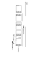
- FIG. 1A shows how the intra slice area moves.
- the number of pictures in which the intra slice area moves from the upper end to the lower end of the picture is called an intra slice period.
- FIG. 1B shows how the intra-column area moves.
- refresh is realized by moving an intra-column area vertically arranged with respect to a picture from the left end to the right end.
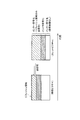
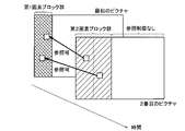
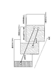
- FIG. 2 is a diagram showing an outline of a coding process of a picture including an intra slice area.
- a region above the intra-slice region only a refresh region in the reference picture (a region where the intra-slice region has passed in the previous picture) can be referred to, and inter-screen prediction (inter prediction) coding is performed.
- intra prediction encoding is performed in the intra slice area.
- inter coding is performed with reference to an arbitrary area in the reference picture.
- a coded block included in the intra slice region is an intra block that performs only intra prediction coding.
- coded blocks that are not included in the intra slice area include both intra blocks for performing intra prediction coding and inter blocks for performing inter coding.
- the present invention has been made in view of the above, and it is an object of the present invention to suppress visual deterioration in image quality in video coding that does not use an I picture.
- a video encoding device is a video encoding device that encodes a picture constituting a video for each pixel block, and generates a predicted image that performs intra prediction encoding or inter prediction encoding of the pixel block.
- a prediction block wherein the prediction image generation unit performs intra-prediction coding on a pixel block included in a first region of a first picture of a predetermined cycle, and performs coding of an n-th (n> 1) picture of the predetermined cycle.
- the pixel blocks included in the n-th region obtained by expanding the (n-1) -th region are subjected to inter prediction coding so that only the pixel blocks included in the m-th region of the m-th (m ⁇ n) picture can be referred to.
- a video encoding method is a video encoding method that encodes a picture constituting a video for each pixel block, and includes a pixel block included in a first region of a first picture of a predetermined cycle. And intra-prediction encoding of the n-th (n> 1) picture of the predetermined cycle, and the pixel block included in the n-th area obtained by expanding the (n ⁇ 1) -th area of the n-th picture (m ⁇ n) And performing inter-prediction coding so that only the pixel blocks included in the m-th region can be referred to.
- FIG. 1A is a diagram illustrating a manner in which an intra slice area moves.
- FIG. 1B is a diagram showing how the intra-column area moves.
- FIG. 2 is a diagram illustrating an outline of a coding process of a picture including an intra slice area.
- FIG. 3 is a functional block diagram illustrating a configuration of the video encoding device according to the present embodiment.
- FIG. 4 is a diagram showing a change in the area to be refreshed.
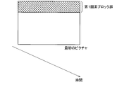
- FIG. 5A is a diagram showing a state where the first pixel block group is set in the first picture in the refresh cycle.
- FIG. 5B is a diagram illustrating a state in which a second pixel block group is set in the second picture in the refresh cycle.
- FIG. 1A is a diagram illustrating a manner in which an intra slice area moves.
- FIG. 1B is a diagram showing how the intra-column area moves.
- FIG. 2 is a diagram illustrating an outline of a coding process of a picture
- FIG. 5C is a diagram illustrating a state where a third pixel block group is set in the third picture in the refresh cycle.
- FIG. 6A is a diagram illustrating a state where the first pixel block group is set in the first picture in the refresh cycle.
- FIG. 6B is a diagram illustrating a state where a second pixel block group is set in the second picture in the refresh cycle.
- FIG. 6C is a diagram illustrating a state where a third pixel block group is set in the third picture in the refresh cycle.
- FIG. 7A is a diagram illustrating a state where the first pixel block group is set in the first picture of the refresh cycle.
- FIG. 7B is a diagram showing a state where the second pixel block group is set in the second picture in the refresh cycle.
- FIG. 7C is a diagram illustrating a state where a third pixel block group is set in the third picture in the refresh cycle.
- FIG. 3 is a functional block diagram showing the configuration of the video encoding device 1 of the present embodiment.
- the video encoding device 1 shown in FIG. 1 includes an adder A, an orthogonal transform unit 11, a quantization unit 12, a variable length encoding unit 13, a quantization control unit 14, an inverse quantization unit 15, an inverse orthogonal transform unit 16, An adder B and a predicted image generation unit 17 are provided.
- the adder A generates a prediction residual by subtracting the prediction image generated by the prediction image generation unit 17 from the input picture constituting the video.
- the orthogonal transform unit 11 performs an orthogonal transform such as a discrete cosine transform on the prediction residual output from the adder A.
- the quantization unit 12 quantizes the orthogonally transformed transform residual coefficients using the quantization parameters output from the quantization control unit 14.
- the variable-length encoding unit 13 encodes the quantized transform coefficients of the prediction residual by a predetermined encoding method capable of reversible processing, and outputs encoded data.
- the quantization control unit 14 determines a quantization parameter using a generated code amount obtained from the input picture and the data amount output from the variable length coding unit 13 and the like.
- the output of the quantization unit 12 is input to the variable-length encoding unit 13 and also to the inverse quantization unit 15.
- the inverse quantization unit 15 inversely quantizes the output of the quantization unit 12 and decodes the transform coefficients of the prediction residual.
- the inverse orthogonal transform unit 16 performs an inverse orthogonal transform on the output of the inverse quantization unit 15 to decode the prediction residual.
- the adder B adds the prediction image generated by the prediction image generation unit 17 and the prediction residual decoded by the inverse orthogonal transform unit 16 to generate a locally decoded image.
- the predicted image generation unit 17 includes an intra prediction unit 171 and an inter prediction unit 172.
- the prediction image generation unit 17 switches the output of the intra prediction unit 171 or the inter prediction unit 172 according to the prediction efficiency for each coding target block.
- the video encoding device 1 is based on H.264. H.264 / AVC or H.264. Since encoded data conforming to a video encoding standard such as H.265 / HEVC is generated, many processes are performed in block units.
- the intra-prediction unit 171 performs intra-prediction coding of a pixel block using a pixel value of a locally decoded image using a correlation between neighboring pixels.
- the inter prediction unit 172 performs inter prediction coding of the pixel block using the motion information of the coding target detected from the frame before or after the locally decoded image.
- the predicted image generation unit 17 inserts a set of pixel blocks (first pixel block group) to be subjected to intra prediction encoding into the first picture in the refresh cycle, and in the second and subsequent pictures in the refresh cycle, the n-th picture (n> 1) ),
- the pixel blocks in the n-th pixel block group are inter-prediction-coded so that only the m-th pixel block group in the m-th (m ⁇ n) picture (reference picture) can be referred to.
- the predicted image generation unit 17 expands the n-th pixel block group of the n-th picture to include the area adjacent to the (n-1) -th pixel block group of the (n-1) -th picture.
- the first pixel block group of the first picture is a refreshed area in which the error in the previous refresh cycle has not been propagated.
- the second pixel block group that has been inter-prediction coded with reference to only the first pixel block group of the second picture is also a refreshed area.
- the area that has been inter-prediction coded with reference to only the refreshed area in the reference picture is a refreshed area. Since the predicted image generation unit 17 inserts the first pixel block group to be subjected to intra prediction encoding only into the first picture in the refresh cycle, a difference in image quality occurs between the region subjected to intra prediction encoding and the region subjected to inter prediction encoding. Hateful.
- FIG. 4 shows the change of the area to be refreshed.
- FIG. 4 shows four pictures in the refresh cycle, but the present invention is not limited to this, and the number of pictures in the refresh cycle can be set arbitrarily.
- the first pixel block group 110A to be subjected to intra prediction encoding is a refreshed area.
- the second pixel block group 110B including the first pixel block group 110A and the area adjacent to the first pixel block group 110A is a region to be refreshed.
- the pixel blocks of the second pixel block group 110B are inter-prediction coded so that only the first pixel block group 110A of the picture 100A can be referred to.
- the third pixel block group 110C including the second pixel block group 110B and the area adjacent to the second pixel block group 110B is a region to be refreshed.
- the pixel blocks of the third pixel block group 110C are inter-prediction coded so that only the first pixel block group 110A of the picture 100A and the second pixel block group 110B of the picture 100B can be referred to.
- the entire picture is an area to be refreshed.
- the pixel block of the last picture 100D is inter-prediction coded so that only the second pixel block group 110B and the third pixel block group 110C of the previous or two previous pictures 100B and 100C can be referred to.
- the first pixel block group to be subjected to intra prediction encoding is inserted into the first picture in the same manner as described above, and the area to be refreshed in subsequent pictures is expanded.
- the predicted image generation unit 17 inserts a set of pixel blocks (first pixel block group) to be subjected to intra prediction encoding at the upper end of the first picture in the refresh cycle.
- the intra prediction unit 171 performs intra prediction encoding on the pixel blocks in the first pixel block group.
- Pixel blocks other than the first pixel block group are subjected to inter prediction coding by the inter prediction unit 172.
- Pixel blocks other than the first pixel block group may switch between intra prediction encoding and inter prediction encoding according to prediction efficiency. The same applies to pixel blocks other than the n-th pixel block group described below.
- the first pixel block group shown in FIG. 5A corresponds to a band-like intra slice (horizontal band) extended in the horizontal direction in the picture.
- the first pixel block group is not limited to an intra slice, but may be a band-like intra column (vertical band) that is vertically extended in a picture, which will be described later.
- the first pixel block group may be composed of pixel blocks included in a closed region located at the end of the picture.
- the first pixel block group to be subjected to intra prediction encoding may be a part of the horizontal band in FIG. 5A.
- the predicted image generation unit 17 assigns the first pixel block group and a set of pixel blocks in an area adjacent to the first pixel block group of the second picture to a second pixel block group.
- the width of the second pixel block group is desirably about twice the width of the first pixel block group.
- the pixel block of the second pixel block group is subjected to inter prediction coding by the inter prediction unit 172 so that only the first pixel block group in the first picture can be referred to. Pixel blocks other than the second pixel block group are subjected to inter prediction coding by the inter prediction unit 172 without reference restriction.
- the predicted image generation unit 17 defines a set of pixel blocks in the second picture block group and an area adjacent to the second picture block group in the third picture as a third picture block group. I do.
- the width of the third pixel block group is desirably about the sum of the width of the second pixel block group and the width of the first pixel block group.
- the inter prediction unit 172 performs inter prediction coding on the pixel blocks of the third pixel block group so that only the first pixel block group in the first picture and the second pixel block group in the second picture can be referred to. Pixel blocks other than the third pixel block group are subjected to inter prediction coding by the inter prediction unit 172 without reference restriction.
- the predicted image generation unit 17 also refreshes the region (the fourth image block group, the fifth image block group,...) That restricts the region that can be referred to in the inter prediction coding even after the fourth picture.
- the region to be expanded is expanded, and the pixel blocks in the region are subjected to inter prediction coding so that only the refreshed region in the reference picture can be referred to.
- the predicted image generation unit 17 inserts the first pixel block group into the first picture of a new refresh cycle.
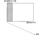
- the predicted image generation unit 17 inserts a vertical pixel band first pixel block group into the left end of the first picture in the refresh cycle.
- the intra prediction unit 171 performs intra prediction encoding on the pixel blocks in the first pixel block group. Pixel blocks other than the first pixel block group are subjected to inter prediction coding by the inter prediction unit 172. Pixel blocks other than the first pixel block group may switch between intra prediction encoding and inter prediction encoding according to prediction efficiency. The same applies to pixel blocks other than the n-th pixel block group described below.
- the predicted image generation unit 17 determines the first pixel block group and the set of pixel blocks in the right region adjacent to the first pixel block group in the second picture as a second pixel block. Group.
- the width of the second pixel block group is desirably about twice the width of the first pixel block group.
- the pixel block of the second pixel block group is subjected to inter prediction coding by the inter prediction unit 172 so that only the first pixel block group in the first picture can be referred to. Pixel blocks other than the second pixel block group are subjected to inter prediction coding by the inter prediction unit 172 without reference restriction.
- the predicted image generation unit 17 converts the set of pixel blocks in the third picture into the second pixel block group and the right region adjacent to the second pixel block group into the third pixel block. Group.
- the width of the third pixel block group is desirably about the sum of the width of the second pixel block group and the width of the first pixel block group.
- the inter prediction unit 172 performs inter prediction coding on the pixel blocks of the third pixel block group so that only the first pixel block group in the first picture and the second pixel block group in the second picture can be referred to. Pixel blocks other than the third pixel block group are subjected to inter prediction coding by the inter prediction unit 172 without reference restriction.
- the predicted image generation unit 17 extends the refreshed area to the right in the fourth and subsequent pictures, and sets the pixel blocks of the refreshed area to be only the refreshed area in the reference picture. Perform predictive encoding.
- the predicted image generation unit 17 inserts a horizontal band first pixel block group into each of the upper end and the lower end of the first picture in the refresh cycle.
- the intra prediction unit 171 performs intra prediction encoding on the pixel blocks in the first pixel block group. Pixel blocks other than the first pixel block group are subjected to inter prediction coding by the inter prediction unit 172. Pixel blocks other than the first pixel block group may switch between intra prediction encoding and inter prediction encoding according to prediction efficiency. The same applies to pixel blocks other than the n-th pixel block group described below.
- the prediction image generation unit 17 generates a set of pixel blocks in two regions adjacent to the center of each of the first pixel block group and the first pixel block group in the second picture. Is a second pixel block group.
- the pixel block of the second pixel block group is subjected to inter prediction coding by the inter prediction unit 172 so that only the first pixel block group in the first picture can be referred to.
- the pixel blocks of the second pixel block group at the lower end of the picture may refer to the first pixel block group at the upper end of the reference picture, or the pixel blocks of the second pixel block group at the upper end of the picture may be referred to.
- the first pixel block group at the lower end of the picture may be referred to.
- Pixel blocks other than the second pixel block group are subjected to inter prediction coding by the inter prediction unit 172 without reference restriction.
- the prediction image generation unit 17 generates a set of pixel blocks in the second picture and two areas adjacent to the center of each of the second pixel block group and the second pixel block group in the third picture. Is a third pixel block group.
- the inter prediction unit 172 performs inter prediction coding on the pixel blocks of the third pixel block group so that only the first pixel block group in the first picture and the second pixel block group in the second picture can be referred to.
- the pixel blocks of the third pixel block group at the lower end of the picture may refer to the first and second pixel block groups at the upper end of the reference picture, or the pixel blocks of the third pixel block group at the upper end of the picture. May refer to the first and second pixel block groups at the lower end of the reference picture. Pixel blocks other than the third pixel block group are subjected to inter prediction coding by the inter prediction unit 172 without reference restriction.
- the predicted image generation unit 17 similarly extends the refreshed area toward the inside of the picture after the fourth picture, and the pixel blocks of the refreshed area include only the refreshed area in the reference picture. Inter prediction coding is performed as a reference.
- the first pixel block may be inserted on the left and right sides of the picture to extend the refreshed area from the left and right ends of the picture toward the center.
- the predicted image generation unit 17 performs intra prediction encoding on the pixel blocks included in the first pixel block group of the first picture in the refresh cycle, and performs n-th ( A pixel block included in an n-th pixel block group (an area obtained by expanding the (n-1) -th pixel block group) of a picture of (n> 1) is a pixel included in an m-th pixel block group of an m-th (m ⁇ n) picture.
- intra-slice regions do not move in video coding that does not use I-pictures, so that visual image quality degradation can be suppressed.
- the pixel blocks included in the n-th pixel block group (the area obtained by expanding the (n-1) -th pixel block group) of the n-th (n> 1) picture in the refresh cycle depend on the prediction efficiency. It is also possible to switch between intra prediction coding and inter prediction coding.
Landscapes
- Engineering & Computer Science (AREA)
- Multimedia (AREA)
- Signal Processing (AREA)
- Compression Or Coding Systems Of Tv Signals (AREA)
Abstract
予測画像生成部(17)が、リフレッシュ周期の最初のピクチャの第1画素ブロック群に含まれる画素ブロックをイントラ予測符号化し、リフレッシュ周期のn番目(n>1)のピクチャの第n画素ブロック群(第n-1画素ブロック群を拡張した領域)に含まれる画素ブロックをm番目(m<n)のピクチャの第m画素ブロック群に含まれる画素ブロックのみを参照可能としてインター予測符号化する。
Description
本発明は、映像を符号化する技術に関する。
リアルタイムに映像通信を行う場合、映像送信側でピクチャを取得してから映像受信側でピクチャを表示するまでに要する時間(遅延時間)を短縮することが望まれる。映像の符号化処理/復号処理による遅延時間を短縮する技術の1つとして、イントラスライスあるいはイントラコラムと呼ばれる技術が知られている。
イントラスライスを利用した映像符号化では、画面内だけで独立して符号化することで得られるIピクチャを利用しない代わりに、符号化ブロックを強制的に画面内予測(イントラ予測)符号化するイントラスライス領域をピクチャ単位で上から下に移動させてリフレッシュを実現する。図1Aにイントラスライス領域が移動する様子を示す。イントラスライス領域がピクチャの上端から下端に移動するピクチャ数をイントラスライス周期と呼ぶ。図1Bに、イントラコラム領域が移動する様子を示す。イントラコラムを利用した映像符号化では、ピクチャに対して縦に配置したイントラコラム領域を左端から右端に移動させてリフレッシュを実現する。
図2は、イントラスライス領域を含むピクチャの符号化処理の概要を示す図である。イントラスライス領域より上の領域では、参照ピクチャにおけるリフレッシュ領域(以前のピクチャでイントラスライス領域が通過した領域)のみを参照可能として、画面間予測(インター予測)符号化を行う。イントラスライス領域では、イントラ予測符号化を行う。イントラスライス領域より下の領域では、参照ピクチャ中の任意の領域を参照してインター符号化を行う。
イントラスライス領域に含まれる符号化ブロックは、イントラ予測符号化のみを行うイントラブロックである。一方、イントラスライス領域に含まれない符号化ブロックは、イントラ予測符号化を行うイントラブロックとインター符号化を行うインターブロックが混在する。映像の特性あるいは要求されるビットレートなどによっては、イントラスライス領域と非イントラスライス領域とで画質に差が生じることがある。その結果、イントラスライスを利用した符号化では、復号した映像中にイントラスライス領域が移動する様子が見えてしまい、視覚的な画質劣化を生じることがあるという課題があった。
本発明は、上記に鑑みてなされたものであり、Iピクチャを利用しない映像符号化において、視覚的な画質劣化を抑制することを目的とする。
本発明の一態様の映像符号化装置は、映像を構成するピクチャを画素ブロックごとに符号化する映像符号化装置であって、前記画素ブロックをイントラ予測符号化またはインター予測符号化する予測画像生成部を有し、前記予測画像生成部は、所定の周期の1番目のピクチャの第1領域に含まれる画素ブロックをイントラ予測符号化し、前記所定の周期のn番目(n>1)のピクチャの第n-1領域を広げた第n領域に含まれる画素ブロックをm番目(m<n)のピクチャの第m領域に含まれる画素ブロックのみを参照可能としてインター予測符号化する。
本発明の一態様の映像符号化方法は、映像を構成するピクチャを画素ブロックごとに符号化する映像符号化方法であって、所定の周期の1番目のピクチャの第1領域に含まれる画素ブロックをイントラ予測符号化するステップと、前記所定の周期のn番目(n>1)のピクチャの第n-1領域を広げた第n領域に含まれる画素ブロックをm番目(m<n)のピクチャの第m領域に含まれる画素ブロックのみを参照可能としてインター予測符号化するステップと、を有する。
本発明によれば、Iピクチャを利用しない映像符号化において、視覚的な画質劣化を抑制することができる。
以下、本発明の実施の形態について図面を用いて説明する。
図3は、本実施形態の映像符号化装置1の構成を示す機能ブロック図である。同図に示す映像符号化装置1は、加算器A、直交変換部11、量子化部12、可変長符号化部13、量子化制御部14、逆量子化部15、逆直交変換部16、加算器B、及び予測画像生成部17を備える。
加算器Aは、映像を構成する入力ピクチャから、予測画像生成部17が生成した予測画像を減算して予測残差を生成する。直交変換部11は、加算器Aの出力である予測残差に対し、離散コサイン変換などの直交変換を施す。量子化部12は、量子化制御部14から出力された量子化パラメータを用いて、直交変換された予測残差の変換係数を量子化する。可変長符号化部13は、量子化された予測残差の変換係数を、可逆的な処理が可能な所定の符号化方式により符号化して符号化データを出力する。量子化制御部14は、入力ピクチャおよび可変長符号化部13が出力するデータ量等から得られる発生符号量を用いて量子化パラメータを決定する。
量子化部12の出力は、可変長符号化部13に入力されるとともに、逆量子化部15にも入力される。逆量子化部15は、量子化部12の出力を逆量子化して予測残差の変換係数を復号する。逆直交変換部16は、逆量子化部15の出力を逆直交変換して予測残差を復号する。加算器Bは、予測画像生成部17が生成した予測画像と逆直交変換部16が復号した予測残差とを加算し、局所復号画像を生成する。
予測画像生成部17は、イントラ予測部171およびインター予測部172を備える。予測画像生成部17は、符号化対象ブロックごとに、予測効率に応じてイントラ予測部171又はインター予測部172の出力を切り替える。映像符号化装置1は、H.264/AVCあるいはH.265/HEVCなどの映像符号化標準に準拠する符号化データを生成することから、多くの処理がブロック単位で行われる。イントラ予測部171は、近接画素間の相関関係を利用し、局所復号画像の画素値を用いて画素ブロックをイントラ予測符号化する。インター予測部172は、局所復号画像の前方あるいは後方のフレームから検出される符号化対象の動き情報を用いて画素ブロックをインター予測符号化する。
予測画像生成部17は、リフレッシュ周期の最初のピクチャにイントラ予測符号化する画素ブロックの集合(第1画素ブロック群)を挿入し、リフレッシュ周期の2番目以降のピクチャでは、n番目(n>1)のピクチャの第n画素ブロック群の画素ブロックを、m番目(m<n)のピクチャ(参照ピクチャ)中の第m画素ブロック群のみを参照可能としてインター予測符号化する。予測画像生成部17は、n番目のピクチャの第n画素ブロック群を、n-1番目のピクチャの第n-1画素ブロック群に隣接する領域を含めて広げる。
最初のピクチャの第1画素ブロック群は、前のリフレッシュ周期での誤りが伝播されていないリフレッシュされた領域となる。また、2番目のピクチャの第1画素ブロック群のみを参照してインター予測符号化された第2画素ブロック群もリフレッシュされた領域となる。3番目以降のピクチャにおいても参照ピクチャ中のリフレッシュされた領域のみを参照してインター予測符号化された領域はリフレッシュされた領域となる。予測画像生成部17は、リフレッシュ周期の最初のピクチャのみにイントラ予測符号化する第1画素ブロック群を挿入するので、イントラ予測符号化した領域とインター予測符号化した領域との画質の差が生じにくい。
図4にリフレッシュされる領域の変化を示す。図4では、リフレッシュ周期内に4つのピクチャを示しているが、これに限定するものではなく、リフレッシュ周期内のピクチャ数は任意に設定できる。
リフレッシュ周期の最初のピクチャ100Aでは、イントラ予測符号化する第1画素ブロック群110Aがリフレッシュされた領域となる。
2番目のピクチャ100Bでは、第1画素ブロック群110Aと第1画素ブロック群110Aに隣接した領域を含む第2画素ブロック群110Bがリフレッシュされる領域である。第2画素ブロック群110Bの画素ブロックは、ピクチャ100Aの第1画素ブロック群110Aのみを参照可能としてインター予測符号化される。
3番目のピクチャ100Cでは、第2画素ブロック群110Bと第2画素ブロック群110Bに隣接した領域を含む第3画素ブロック群110Cがリフレッシュされる領域である。第3画素ブロック群110Cの画素ブロックは、ピクチャ100Aの第1画素ブロック群110Aおよびピクチャ100Bの第2画素ブロック群110Bのみを参照可能としてインター予測符号化される。
リフレッシュ周期の最後のピクチャ100Dでは、ピクチャ全体がリフレッシュされる領域となる。最後のピクチャ100Dの画素ブロックは、1つ前または2つ前のピクチャ100B,100Cの第2画素ブロック群110Bと第3画素ブロック群110Cのみを参照可能としてインター予測符号化される。
次のリフレッシュ周期では、上記と同様に、最初のピクチャにイントラ予測符号化する第1画素ブロック群を挿入し、以降のピクチャにおいて、リフレッシュされる領域を広げていく。
次に、予測画像生成部の処理について説明する。
予測画像生成部17は、図5Aに示すように、リフレッシュ周期の最初のピクチャの上端部に、イントラ予測符号化する画素ブロックの集合(第1画素ブロック群)を挿入する。第1画素ブロック群の画素ブロックは、イントラ予測部171がイントラ予測符号化する。第1画素ブロック群以外の画素ブロックは、インター予測部172がインター予測符号化する。第1画素ブロック群以外の画素ブロックは、予測効率に応じてイントラ予測符号化とインター予測符号化を切り替えてもよい。以下で説明する第n画素ブロック群以外の画素ブロックについても同様である。
図5Aに示す第1画素ブロック群は、ピクチャ中で横方向に延伸された帯状のイントラスライス(横帯)に相当する。第1画素ブロック群は、イントラスライスに限定するものではなく、後述の、ピクチャ中で縦方向に延伸された帯状のイントラコラム(縦帯)でもよい。第1画素ブロック群は、ピクチャの端部に位置する閉じた領域に含まれる画素ブロックで構成されればよい。例えば、イントラ予測符号化する第1画素ブロック群は図5Aの横帯の一部であってもよい。
続いて、予測画像生成部17は、図5Bに示すように、2番目のピクチャの、第1画素ブロック群と第1画素ブロック群に隣接する領域の画素ブロックの集合を第2画素ブロック群とする。第2画素ブロック群の幅は、第1画素ブロック群の幅の2倍程度が望ましい。第2画素ブロック群の画素ブロックは、最初のピクチャ中の第1画素ブロック群のみを参照可能としてインター予測部172がインター予測符号化する。第2画素ブロック群以外の画素ブロックは、参照制限なしでインター予測部172がインター予測符号化する。
続いて、予測画像生成部17は、図5Cに示すように、3番目のピクチャの、第2画素ブロック群と第2画素ブロック群に隣接する領域の画素ブロックの集合を第3画素ブロック群とする。第3画素ブロック群の幅は、第2画素ブロック群の幅に第1画素ブロック群の幅を加えた程度が望ましい。第3画素ブロック群の画素ブロックは、最初のピクチャ中の第1画素ブロック群および2番目のピクチャ中の第2画素ブロック群のみを参照可能としてインター予測部172がインター予測符号化する。第3画素ブロック群以外の画素ブロックは、参照制限なしでインター予測部172がインター予測符号化する。
予測画像生成部17は、4番目のピクチャ以降においても、インター予測符号化の際に参照可能な領域を制限する領域(第4画像ブロック群、第5画像ブロック群、・・・)つまりリフレッシュされる領域を広げていき、その領域の画素ブロックは参照ピクチャ中のリフレッシュされた領域のみを参照可能としてインター予測符号化する。
リフレッシュ周期の最後のピクチャは、リフレッシュされる領域がピクチャの全体となる。この最後のピクチャの次のピクチャは、新たなリフレッシュ周期の最初のピクチャである。予測画像生成部17は、図5Aに戻り、新たなリフレッシュ周期の最初のピクチャに第1画素ブロック群を挿入する。
次に、ピクチャの横方向にリフレッシュする例について説明する。
予測画像生成部17は、図6Aに示すように、リフレッシュ周期の最初のピクチャの左端部に縦帯の第1画素ブロック群を挿入する。第1画素ブロック群の画素ブロックは、イントラ予測部171がイントラ予測符号化する。第1画素ブロック群以外の画素ブロックは、インター予測部172がインター予測符号化する。第1画素ブロック群以外の画素ブロックは、予測効率に応じてイントラ予測符号化とインター予測符号化を切り替えてもよい。以下で説明する第n画素ブロック群以外の画素ブロックについても同様である。
続いて、予測画像生成部17は、図6Bに示すように、2番目のピクチャの、第1画素ブロック群と第1画素ブロック群に隣接する右側の領域の画素ブロックの集合を第2画素ブロック群とする。第2画素ブロック群の幅は、第1画素ブロック群の幅の2倍程度が望ましい。第2画素ブロック群の画素ブロックは、最初のピクチャ中の第1画素ブロック群のみを参照可能としてインター予測部172がインター予測符号化する。第2画素ブロック群以外の画素ブロックは、参照制限なしでインター予測部172がインター予測符号化する。
続いて、予測画像生成部17は、図6Cに示すように、3番目のピクチャの、第2画素ブロック群と第2画素ブロック群に隣接する右側の領域の画素ブロックの集合を第3画素ブロック群とする。第3画素ブロック群の幅は、第2画素ブロック群の幅に第1画素ブロック群の幅を加えた程度が望ましい。第3画素ブロック群の画素ブロックは、最初のピクチャ中の第1画素ブロック群および2番目のピクチャ中の第2画素ブロック群のみを参照可能としてインター予測部172がインター予測符号化する。第3画素ブロック群以外の画素ブロックは、参照制限なしでインター予測部172がインター予測符号化する。
予測画像生成部17は、4番目のピクチャ以降も同様に、リフレッシュされる領域を右方向へ広げていき、リフレッシュされる領域の画素ブロックは参照ピクチャ中のリフレッシュされた領域のみを参照可能としてインター予測符号化する。
次に、ピクチャの上下端から中央に向けてリフレッシュする例について説明する。
予測画像生成部17は、図7Aに示すように、リフレッシュ周期の最初のピクチャの上端部と下端部のそれぞれに横帯の第1画素ブロック群を挿入する。第1画素ブロック群の画素ブロックは、イントラ予測部171がイントラ予測符号化する。第1画素ブロック群以外の画素ブロックは、インター予測部172がインター予測符号化する。第1画素ブロック群以外の画素ブロックは、予測効率に応じてイントラ予測符号化とインター予測符号化を切り替えてもよい。以下で説明する第n画素ブロック群以外の画素ブロックについても同様である。
続いて、予測画像生成部17は、図7Bに示すように、2番目のピクチャの、第1画素ブロック群と第1画素ブロック群のそれぞれの中央側に隣接する2つの領域の画素ブロックの集合を第2画素ブロック群とする。第2画素ブロック群の画素ブロックは、最初のピクチャ中の第1画素ブロック群のみを参照可能としてインター予測部172がインター予測符号化する。ピクチャの下端部の第2画素ブロック群の画素ブロックは、参照ピクチャの上端部の第1画素ブロック群を参照してもよいし、ピクチャの上端部の第2画素ブロック群の画素ブロックは、参照ピクチャの下端部の第1画素ブロック群を参照してもよい。第2画素ブロック群以外の画素ブロックは、参照制限なしでインター予測部172がインター予測符号化する。
続いて、予測画像生成部17は、図7Cに示すように、3番目のピクチャの、第2画素ブロック群と第2画素ブロック群のそれぞれの中央側に隣接する2つの領域の画素ブロックの集合を第3画素ブロック群とする。第3画素ブロック群の画素ブロックは、最初のピクチャ中の第1画素ブロック群および2番目のピクチャ中の第2画素ブロック群のみを参照可能としてインター予測部172がインター予測符号化する。ピクチャの下端部の第3画素ブロック群の画素ブロックは、参照ピクチャの上端部の第1、第2画素ブロック群を参照してもよいし、ピクチャの上端部の第3画素ブロック群の画素ブロックは、参照ピクチャの下端部の第1、第2画素ブロック群を参照してもよい。第3画素ブロック群以外の画素ブロックは、参照制限なしでインター予測部172がインター予測符号化する。
予測画像生成部17は、4番目のピクチャ以降も同様に、リフレッシュされる領域をピクチャの内側に向けて拡張していき、リフレッシュされる領域の画素ブロックは参照ピクチャ中のリフレッシュされた領域のみを参照可能としてインター予測符号化する。
なお、ピクチャの左右に第1画素ブロックを挿入し、ピクチャの左右端部から中央に向けてリフレッシュされる領域を拡張してもよい。
以上説明したように、本実施の形態によれば、予測画像生成部17が、リフレッシュ周期の最初のピクチャの第1画素ブロック群に含まれる画素ブロックをイントラ予測符号化し、リフレッシュ周期のn番目(n>1)のピクチャの第n画素ブロック群(第n-1画素ブロック群を拡張した領域)に含まれる画素ブロックをm番目(m<n)のピクチャの第m画素ブロック群に含まれる画素ブロックのみを参照可能としてインター予測符号化することで、Iピクチャを利用しない映像符号化において、イントラスライス領域が移動しないので、視覚的な画質劣化を抑制することができる。
なお、上記各実施例において、リフレッシュ周期のn番目(n>1)のピクチャの第n画素ブロック群(第n-1画素ブロック群を拡張した領域)に含まれる画素ブロックは、予測効率に応じてイントラ予測符号化とインター予測符号化を切り替えてもよい。
1…映像符号化装置
11…直交変換部
12…量子化部
13…可変長符号化部
14…量子化制御部
15…逆量子化部
16…逆直交変換部
17…予測画像生成部
171…イントラ予測部
172…インター予測部
A,B…加算器
11…直交変換部
12…量子化部
13…可変長符号化部
14…量子化制御部
15…逆量子化部
16…逆直交変換部
17…予測画像生成部
171…イントラ予測部
172…インター予測部
A,B…加算器
Claims (4)
- 映像を構成するピクチャを画素ブロックごとに符号化する映像符号化装置であって、
前記画素ブロックをイントラ予測符号化またはインター予測符号化する予測画像生成部を有し、
前記予測画像生成部は、所定の周期の1番目のピクチャの第1領域に含まれる画素ブロックをイントラ予測符号化し、
前記所定の周期のn番目(n>1)のピクチャの第n-1領域を広げた第n領域に含まれる画素ブロックをm番目(m<n)のピクチャの第m領域に含まれる画素ブロックのみを参照可能としてインター予測符号化することを特徴とする映像符号化装置。 - 前記第1領域は、前記ピクチャの端部に位置し、当該端部に沿って延びる領域であり、
前記第n領域は、前記第n-1領域と前記第n-1領域に沿って延びる帯状の領域を合わせた領域であることを特徴とする請求項1に記載の映像符号化装置。 - 映像を構成するピクチャを画素ブロックごとに符号化する映像符号化方法であって、
所定の周期の1番目のピクチャの第1領域に含まれる画素ブロックをイントラ予測符号化するステップと、
前記所定の周期のn番目(n>1)のピクチャの第n-1領域を広げた第n領域に含まれる画素ブロックをm番目(m<n)のピクチャの第m領域に含まれる画素ブロックのみを参照可能としてインター予測符号化するステップと、
を有することを特徴とする映像符号化方法。 - 前記第1領域は、前記ピクチャの端部に位置し、当該端部に沿って延びる領域であり、
前記第n領域は、前記第n-1領域と前記第n-1領域に沿って延びる帯状の領域を合わせた領域であることを特徴とする請求項3に記載の映像符号化方法。
Applications Claiming Priority (2)
| Application Number | Priority Date | Filing Date | Title |
|---|---|---|---|
| JP2018187433A JP2020057936A (ja) | 2018-10-02 | 2018-10-02 | 映像符号化装置および映像符号化方法 |
| JP2018-187433 | 2018-10-02 |
Publications (1)
| Publication Number | Publication Date |
|---|---|
| WO2020071311A1 true WO2020071311A1 (ja) | 2020-04-09 |
Family
ID=70055553
Family Applications (1)
| Application Number | Title | Priority Date | Filing Date |
|---|---|---|---|
| PCT/JP2019/038505 Ceased WO2020071311A1 (ja) | 2018-10-02 | 2019-09-30 | 映像符号化装置および映像符号化方法 |
Country Status (2)
| Country | Link |
|---|---|
| JP (1) | JP2020057936A (ja) |
| WO (1) | WO2020071311A1 (ja) |
Citations (2)
| Publication number | Priority date | Publication date | Assignee | Title |
|---|---|---|---|---|
| JP2005020781A (ja) * | 2004-08-30 | 2005-01-20 | Oki Electric Ind Co Ltd | 符号化装置、復号化装置及び伝送システム |
| WO2010035505A1 (ja) * | 2008-09-29 | 2010-04-01 | パナソニック株式会社 | 動画像符号化方法および動画像符号化装置 |
-
2018
- 2018-10-02 JP JP2018187433A patent/JP2020057936A/ja active Pending
-
2019
- 2019-09-30 WO PCT/JP2019/038505 patent/WO2020071311A1/ja not_active Ceased
Patent Citations (2)
| Publication number | Priority date | Publication date | Assignee | Title |
|---|---|---|---|---|
| JP2005020781A (ja) * | 2004-08-30 | 2005-01-20 | Oki Electric Ind Co Ltd | 符号化装置、復号化装置及び伝送システム |
| WO2010035505A1 (ja) * | 2008-09-29 | 2010-04-01 | パナソニック株式会社 | 動画像符号化方法および動画像符号化装置 |
Also Published As
| Publication number | Publication date |
|---|---|
| JP2020057936A (ja) | 2020-04-09 |
Similar Documents
| Publication | Publication Date | Title |
|---|---|---|
| US12058369B2 (en) | Method and apparatus for decoding video signal | |
| KR102120135B1 (ko) | 마지막 프레임 모션 벡터 파티셔닝 | |
| US9001890B2 (en) | Method and apparatus for video intraprediction encoding and decoding | |
| KR101292093B1 (ko) | 화면내 예측 부호화를 위한 영상 부호화/복호화 장치 및 방법 | |
| US8165195B2 (en) | Method of and apparatus for video intraprediction encoding/decoding | |
| CN107087170B (zh) | 编码设备、编码方法、解码设备和解码方法 | |
| TWI674793B (zh) | 視訊編解碼的適應性預測候選位置 | |
| EP2755388B1 (en) | Method, device, and program for encoding and decoding image | |
| US20070053443A1 (en) | Method and apparatus for video intraprediction encoding and decoding | |
| US10298943B2 (en) | Compression of pictures | |
| KR20140124448A (ko) | 인트라 예측을 이용한 비디오 부호화/복호화 방법 및 장치 | |
| KR20140129417A (ko) | 복수의 트랜스폼들을 이용한 영상 부호화/복호화 방법 및 장치 | |
| JP7728429B2 (ja) | 画像復号装置、画像復号方法及びプログラム | |
| WO2020071311A1 (ja) | 映像符号化装置および映像符号化方法 | |
| EP4584951A1 (en) | Filter coefficient derivation simplification for cross-component prediction | |
| JP2025534495A (ja) | 領域ベースの成分間予測 | |
| WO2018216695A1 (ja) | 映像符号化装置および映像符号化方法 | |
| CN113225558A (zh) | 平滑定向和dc帧内预测 | |
| JP2008166916A (ja) | イントラ予測符号化装置およびイントラ予測符号化方法 | |
| KR20140124447A (ko) | 인트라 예측을 이용한 비디오 부호화/복호화 방법 및 장치 | |
| US9277214B2 (en) | Sub-picture hierarchical QP coding | |
| JP2015115614A (ja) | 変換処理方法、逆変換処理方法、変換処理装置、逆変換処理装置、変換処理プログラム及び逆変換処理プログラム | |
| KR20110067648A (ko) | 영상 부호화/복호화 방법 및 이를 수행하는 장치 | |
| KR100728032B1 (ko) | 워핑 기반의 인트라 예측 방법 | |
| JP2015222860A (ja) | 映像符号化装置及び映像符号化プログラム |
Legal Events
| Date | Code | Title | Description |
|---|---|---|---|
| 121 | Ep: the epo has been informed by wipo that ep was designated in this application |
Ref document number: 19868565 Country of ref document: EP Kind code of ref document: A1 |
|
| NENP | Non-entry into the national phase |
Ref country code: DE |
|
| 122 | Ep: pct application non-entry in european phase |
Ref document number: 19868565 Country of ref document: EP Kind code of ref document: A1 |