WO2020071140A1 - Ophthalmologic device and method of operating ophthalmologic device - Google Patents
Ophthalmologic device and method of operating ophthalmologic deviceInfo
- Publication number
- WO2020071140A1 WO2020071140A1 PCT/JP2019/036764 JP2019036764W WO2020071140A1 WO 2020071140 A1 WO2020071140 A1 WO 2020071140A1 JP 2019036764 W JP2019036764 W JP 2019036764W WO 2020071140 A1 WO2020071140 A1 WO 2020071140A1
- Authority
- WO
- WIPO (PCT)
- Prior art keywords
- reflection light
- regular reflection
- light
- optical system
- corneal
- Prior art date
- Legal status (The legal status is an assumption and is not a legal conclusion. Google has not performed a legal analysis and makes no representation as to the accuracy of the status listed.)
- Ceased
Links
Images


Classifications
-
- A—HUMAN NECESSITIES
- A61—MEDICAL OR VETERINARY SCIENCE; HYGIENE
- A61B—DIAGNOSIS; SURGERY; IDENTIFICATION
- A61B3/00—Apparatus for testing the eyes; Instruments for examining the eyes
- A61B3/10—Objective types, i.e. instruments for examining the eyes independent of the patients' perceptions or reactions
- A61B3/101—Objective types, i.e. instruments for examining the eyes independent of the patients' perceptions or reactions for examining the tear film
Definitions
- the present invention relates to an ophthalmologic device which is used for examining the state of the tear film of the subject’s eye and the method of operating the ophthalmologic device.
- the human tear film is primarily constituted of an oily layer (also referred to as a lipid layer), a watery layer, and a mucus layer, from the outermost to the innermost.
- the outermost oily layer is secreted from the meibomian glands located in the inside of the eyelid, and covers the surface of the tear film to prevent the tears from evaporating.
- the watery layer is secreted from the lacrimal glands, moistens the surface of the cornea, and drains into the punctums.
- Dry eye occurs if the tears tend to dry up because the amount of oil secreted from the meibomian glands is reduced due to decrease in meibomian glands, or the amount of the tears (the watery layer) secreted from the lacrimal glands is reduced. Therefore, for diagnosing dry eye, it is necessary to observe change over time of the thickness of the tear film on the surface of the cornea (such as the breaking state of the tear film). Dry eye is a disorder in which the stability of the tear film is decreased because of various factors, and causes ocular discomfort, irregularity in visual performance, etc. and is sometimes accompanied by a failure in the surface of the eye (“Revision of the definition and diagnostic criteria of dry eye in Japan (Nihon no dry eye no lessnessi to shindankijun no kaitei)” (2016 Edition), page 2).
- Patent Literature 1 and Patent Literature 2 disclose ophthalmologic devices, each of which includes an illuminating optical system configured to irradiate the corneal surface of the anterior segment of the subject’s eye with the illumination light (white light), an imaging optical system configured to capture an corneal reflection image produced by the corneal reflection light, which is the illumination light having been reflected by the corneal surface of the subject’s eye, and a determination unit configured to determine the state of the tear film (thickness, etc.) by analyzing the corneal reflection image on the basis of the image signal outputted from the imaging optical system. According to these ophthalmologic devices, the state of the tear film of the subject can be examined in non-contact and non-invasive manner.
- the regular reflection does not occur on the corneal surface even if the distance between the subject’s eye and the objective lens is adjusted by means of, for example, the standard eye (reference eye), since the corneal shape (e.g., the radius of curvature of the cornea) of the subject’s eye differs for each subject.
- the standard eye reference eye
- the corneal shape e.g., the radius of curvature of the cornea
- the illumination light and the corneal reflection light do not interfere (cannot be superimposed) with each other, and no interference figure is generated in the corneal reflection image.
- the present invention has been contrived in view of these circumstances, an object thereof being to provide an ophthalmologic device which can correctly determine the state of the tear film on the corneal surface of the subject’s eye regardless of the corneal shape of the subject’s eye, and a method of operating the ophthalmologic device.
- an ophthalmologic device includes: an objective lens; an illuminating optical system configured to irradiate a cornea of a subject’s eye with illumination light through the objective lens; an incident angle changing mechanism configured to change an incident angle of the illumination light incident to the cornea from the objective lens; an imaging optical system configured to output an image signal by capturing corneal reflection light of the illumination light entering through the objective lens; a regular reflection determination unit configured to, according to the image signal outputted from the imaging optical system, determine whether the corneal reflection light is regular reflection light that is regularly reflected by the cornea; an adjustment control unit configured to, when the regular reflection determination unit determines that the corneal reflection light is not the regular reflection light, adjust the incident angle to an angle at which the corneal reflection light is the regular reflection light by driving the incident angle changing mechanism according to the image signal; an imaging control unit configured to cause the imaging optical system to capture the regular reflection light; and a state determination unit configured to determine a state of a tear film of the subject’s eye according to
- the ophthalmologic device makes it possible, regardless of the corneal shape of the subject’s eye, to obtain the illumination light having been regularly reflected by the corneal surface, in other words, the corneal reflection light can be made the regular reflection light of the illumination light.
- the regular reflection determination unit is configured to, according to a brightness value of the corneal reflection image based on the image signal, determine whether the corneal reflection light is the regular reflection light; and the adjustment control unit is configured to adjust the incident angle according to the brightness value of the corneal reflection image. This makes it possible to have the corneal reflection light be the regular reflection light of the illumination light regardless of the corneal shape of the subject’s eye.
- the incident angle changing mechanism includes a relative movement mechanism configured to cause the objective lens to move relatively to the subject’s eye in an optical axis direction of the objective lens; and the adjustment control unit is configured to, according to the image signal, carry out positioning of the objective lens to a regular reflection position where the corneal reflection light is the regular reflection light by driving the relative movement mechanism. This makes it possible to have the reflection light be the regular reflection light of the illumination light regardless of the corneal shape of the subject’s eye.
- An ophthalmologic device further includes: an alignment determination unit configured to determine alignment of the objective lens to the subject’s eye in the optical axis direction; and an alignment control unit configured to adjust the alignment of the objective lens in the optical axis direction by driving the relative movement mechanism according to a result of determination by the alignment determination unit, wherein the regular reflection determination unit is configured to carry out the determination according to the image signal outputted from the imaging optical system in a state where the alignment of the objective lens is completed.
- the corneal reflection light can be the regular reflection light of the illumination light.
- the state determination unit is configured to determine an interference figure generated on a surface of the cornea from the corneal reflection image, and to determine a thickness of the tear film as the state of the tear film according to the interference figure.
- a method of operating an ophthalmologic device comprising an objective lens, an illuminating optical system configured to irradiate a cornea of a subject’s eye with illumination light through the objective lens, an incident angle changing mechanism configured to change an incident angle of the illumination light incident to the cornea from the objective lens, an imaging optical system configured to output an image signal by capturing corneal reflection light of the illumination light entering through the objective lens
- the method includes: a regular reflection determining step of, according to the image signal outputted from the imaging optical system, determining whether the corneal reflection light is regular reflection light that is regularly reflected by the cornea; an adjustment control step of, when the corneal reflection light is not determined as the regular reflection light in the regular reflection determining step, adjusting the incident angle to an angle at which the corneal reflection light is the regular reflection light by driving the incident angle changing mechanism according to the image signal; an imaging control step of causing the imaging optical system to capture the regular reflection light; and a state determining step of determining a state of
- the present invention it is possible to correctly determine the state of the tear film on the corneal surface of the subject’s eye regardless of the corneal shape of the subject’s eye.
- Fig. 1 is a schematic diagram which illustrates optical systems of an ophthalmologic device.
- Fig. 2 is a functional block diagram of a control device.
- Fig. 3 is an explanatory diagram for explaining examples in which the illumination light is not regularly reflected by the corneal surface.
- Fig. 4 is an explanatory diagram for explaining the positioning control of the first lens group shown in Fig. 3 by the positioning control unit.
- Fig. 5 is a flowchart for explaining the flow of determination processing of the state of the tear film of the subject’s eye by the ophthalmologic device.
- Fig. 1 is a schematic diagram of optical systems of an ophthalmologic device 10.
- the ophthalmologic device 10 includes an anterior segment observing optical system 12, an illuminating optical system 14, a measuring optical system 16 serving as the imaging optical system in the present invention, a focus adjusting system 18, and a control device 20.
- the anterior segment observing optical system 12 includes a first lens group 22 serving as the objective lens in the present invention.
- the anterior segment observing optical system 12 further includes a first semireflecting mirror 24, a lens 26, and an anterior segment camera 28, which are arranged along the optical axis direction OA of the first lens group 22.
- the first lens group 22 is a so-called objective lens and is placed in a lens barrel 30.
- the objective lens (the first lens group 22) includes a plurality of lenses in the present embodiment; however, the objective lens may consist of a single lens.
- the first lens group 22 irradiates the surface of the cornea Ea of the subject’s eye E with the illumination light L1 incident from the first semireflecting mirror 24.
- the corneal reflection light L2 which is the illumination light L1 having been reflected by the corneal surface, is incident to the first lens group 22.
- the corneal reflection light L2 is then incident on the first semireflecting mirror 24 through the first lens group 22.
- the lens barrel 30 is moved by a lens moving system 32 along the optical axis direction OA of the first lens group 22.
- the lens moving system 32 is driven under control by the control device 20, which is described later.
- the lens moving system 32 serves as the relative movement mechanism and the incident angle changing mechanism in the present invention.
- the lens moving system 32 includes a sliding mechanism configured to hold the lens barrel 30 to be slidable parallelly to the optical axis direction OA, and a driving mechanism such as a motor, etc. configured to move the lens barrel 30 back and forth parallelly to the optical axis direction OA.
- the lens moving system 32 can move the first lens group 32 in the optical axis direction OA relatively to the subject’s eye E by moving the lens barrel 30 in the optical axis direction OA.
- the lens moving system 32 is not limited to the motor-driven mechanism, and various driving mechanisms other than motor, such as a solenoid for example, may be used as far as the lens barrel 30 can be moved parallelly to the optical axis direction OA.
- the first semireflecting mirror 24 reflects a part of the illumination light L1 incident from the illuminating optical system 14, which is described later, toward the first lens group 22.
- the first semireflecting mirror 24 transmits a part of the corneal reflection light L2 incident from the first lens group 22 to the lens 26, and reflects the rest of the corneal reflection light L2 toward a second lens group 50 described later.
- the lens 26 transmits the corneal reflection light L2 incident from the first semireflecting mirror 24 to the anterior segment camera 28.
- the anterior segment camera 28 includes a CMOS (complementary metal oxide semiconductor) or CCD (charge-coupled device) type imaging element, and captures an observation image of the anterior segment of the subject’s eye E (hereinafter referred to as the “anterior segment observation image”) produced by the corneal reflection light L2 incident from the lens 26, and outputs the image signal of the anterior segment observation image to the control device 20 described later.
- CMOS complementary metal oxide semiconductor
- CCD charge-coupled device
- the illuminating optical system 14 forms a light path which branches off from the anterior segment observing optical system 12 through the first semireflecting mirror 24.
- the illuminating optical system 14 includes an illumination light source 40.
- the illuminating optical system 14 further includes a lens 42, a variable filter 44, a second semireflecting mirror 46, a mirror 48, and a second lens group 50, which are arranged along the light path OB of the illumination light L1 emitted from the illumination light source 40.
- the illuminating optical system 14 shares the first semireflecting mirror 24 and the first lens group 22 with the anterior segment observing optical system 12.
- the illumination light source 40 emits white light as the illumination light L1 toward the lens 42, and includes a known light source such as an LED (light emitting diode), a halogen lamp, etc. emitting white light.
- the lens 42 transmits the illumination light L1 incident from the illumination light source 40 to the variable filter 44.
- the variable filter 44 transmits the illumination light L1 incident from the lens 42 to the second semireflecting mirror 46 while adjusting the amount of the illumination light L1 incident to the second semireflecting mirror 46.
- the second semireflecting mirror 46 transmits a part of the illumination light L1 incident from the variable filter 44 to the mirror 48, and reflects a part of the corneal reflection light L2 incident from the second lens group 50, which is described later, toward the measuring optical system 16.
- the mirror 48 and the second lens group 50 transmit the illumination light L1 incident from the second semireflecting mirror 46 to the first semireflecting mirror 24, and transmit the corneal reflection light L2 incident from the first semireflecting mirror 24 to the second semireflecting mirror 46.
- the illumination light L1 emitted from the illumination light source 40 passes through the lens 42 to the first semireflecting mirror 24, and is incident to the surface of the cornea Ea through the first lens group 22. This causes the corneal reflection light L2, which is the illumination light L1 having been incident to and reflected by the corneal surface, to be incident to the first lens group 22.
- the measuring optical system 16 forms a light path which branches off from the illuminating optical system 14 through the second semireflecting mirror 46.
- the measuring optical system 16 includes a diaphragm 52, a lens 54 and an interference figure imaging camera 56, and shares a section from the first lens group 22 to the second semireflecting mirror 46 with the illuminating optical system 14.
- the diaphragm 52 and the lens 54 transmit the corneal reflection light L2 incident from the second semireflecting mirror 46 to the interference figure imaging camera 56.
- the interference figure imaging camera 56 includes a CMOS or CCD type imaging element, and captures a corneal reflection image 60 produced by the corneal reflection light L2 incident from the lens 54, and outputs the image signal of the corneal reflection image 60 to the control device 20.
- the focus adjusting system 18 serves as the alignment determination unit in the present invention, and is used for positioning (alignment) of the first lens group 22 in the optical axis direction OA of the subject’s eye E using the optical-lever method.
- the focus adjusting system 18 includes a light emitting unit 18a and a light receiving unit 18b arranged in the circumference of the lens barrel 30. The light emitting unit 18a and the light receiving unit 18b move together with the first lens group 22 and the lens barrel 30 along the optical axis direction OA.
- the light emitting unit 18a emits alignment determining light L3 that is incident to the surface of the cornea Ea from an oblique direction.
- the light receiving unit 18b receives the reflection light L4 that is the alignment determining light L3 having been reflected by the corneal surface.
- the light receiving unit 18b outputs a light receiving signal of the reflection light L4 to the control device 20.
- the light emitting unit 18a and the light receiving unit 18b of the focus adjusting system 18 may be placed in the periphery of the lens 26 after the first semireflecting mirror 24, and cause the alignment determining light L3 and the reflection light L4 to pass through the first lens group 22.
- Fig. 2 is a functional block diagram of the control device 20. As shown in Fig. 2, the control device 20 totally controls the action of each unit of the ophthalmologic device 10.
- the control device 20 is an arithmetic circuit including various processors, memories, etc.
- the various processors include a CPU (Central Processing Unit), a GPU (Graphics Processing Unit), an ASIC (Application Specific Integrated Circuit), and a programmable logical device (for example, SPLD (Simple Programmable Logic Devices), CPLD (Complex Programmable Logic Device), FPGA (Field Programmable Gate Arrays)), etc.
- the various functions of the control device 20 may be realized by a single processor, or by multiple processors of the same or different types.
- the control device 20 is connected with the above-described anterior segment observing optical system 12, illuminating optical system 14, measuring optical system 16, focus adjusting system 18 and lens moving system 32, and further with an operating unit 64, a monitor 66, and a memory unit 68.
- the operating unit 64 includes, for example, a keyboard, a mouse, operating switches, etc. and accepts various operations (such as measurement start operation and setting input operation) by the test staff.
- the monitor 66 includes, for example, a known LCD monitor, and displays the result of examination of the tear film of the subject’s eye E, the anterior segment observation image captured by the anterior segment observing optical system 12, and a screen for displaying various setting of the ophthalmologic device 10, etc.
- the memory unit 68 stores the control program for operation of the ophthalmologic device 10, the results of examination of the tear film of the subject’s eye E, etc.
- the control device 20 functions as an alignment control unit 70, an optical system control unit 72, a regular reflection determination unit 74, a positioning control unit 76, and a state determination unit 78 by running the control program stored in the storage unit 68.
- any part mentioned as a “... unit” may be a “... circuit”, a “... equipment” or a “... device”.
- Any part mentioned as a “... unit” may be composed of any of firmware, software, hardware, or combination thereof.
- the alignment control unit 70 carries out alignment adjustment for the first lens group 22 to the subject’s eye E in the optical axis direction OA by driving the lens moving system 32 on the basis of the light receiving signal inputted from the light receiving unit 18b, before the start of examination with the ophthalmologic device 10.
- the alignment control unit 70 starts operation of the light emitting unit 18a and the light receiving unit 18b of the focus adjusting system 18, and moves the first lens group 22 back and forth along the optical axis direction OA by driving the lens moving system 32. Then, when the reflection light L4 is received by the light receiving unit 18b during the back and forth movement of the first lens group 22, the alignment control unit 70 stops the back and forth movement of the first lens group 22 by the lens moving system 32. Thereby, the first lens group 22 can be settled at the position where the reflection light L4 is received by the light receiving unit 18b, that is, the position where the first lens group 22 is aligned to the subject’s eye E.
- the optical system control unit 72 controls the operations of the anterior segment observing optical system 12, the illuminating optical system 14, and the measuring optical system 16, namely, capture of the anterior segment observation image by the anterior segment observing optical system 12, emission of the illumination light L1 by the illumination light source 40, and capture of the corneal reflection image 60 by the interference figure imaging camera 56.
- the optical system control unit 72 After completion of the alignment by the alignment control unit 70, the optical system control unit 72 causes the illuminating optical system 14 and the measuring optical system 16 to perform temporary (provisional) capturing of the corneal reflection image 60, and when the prescribed condition described below is satisfied, causes the measuring optical system 16, etc. to perform normal (non-provisional) capturing of the corneal reflection image 60.
- the corneal reflection image 60 obtained by the temporary capturing is used for determining whether the illumination light L1 is regularly reflected by the surface of the cornea Ea, that is, whether the corneal reflection light L2 is the regular reflection light of the illumination light L1 (whether it is the regular reflection in which the angle of incidence of the illumination light L1 to the cornea surface is equal to the angle of reflection of the corneal reflection light L2 from the cornea surface) as explained in detail below.
- the corneal reflection image 60 obtained by the normal capturing is used for determining the state of the tear film of the subject’s eye E.
- the tear film may mean each of the oily layer (lipid layer), the watery layer and the mucus layer, or a film composed of two or more of these layers.
- the regular reflection determination unit 74 determines whether the corneal reflection light L2 is the regular reflection light of the illumination light L1 having been regularly reflected by the surface of the cornea Ea.
- the regular reflection here means that the light flux of the illumination light L1 is reflected back to the emission region where the illumination light L1 is emitted from the first lens group 22 (limited to the same position). Accordingly, the corneal reflection light L2 (the regular reflection light) that is the illumination light L1 having been emitted from an arbitrary region of the first lens group 22 and regularly reflected by the corneal surface is incident to the original region.
- the emission region of the illumination light L1 in the first lens group 22 coincides (or substantially coincides) with the incident region where the corneal reflection light L2 that is the regular reflection light of the illumination light L1 is incident to the first lens group 22.
- An example of the regular reflection light includes the perpendicularly reflected light that is the illumination light L1 perpendicularly incident to the corneal surface and perpendicularly reflected by the corneal surface; however, the regular reflection light is not limited to the perpendicularly reflected light.
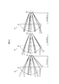
- Fig. 3 is an explanatory diagram for explaining examples of the cases where the illumination light L1 is not regularly reflected by the surface of the cornea Ea (the case in which the corneal reflection light L2 is not the regular reflection light).
- the distance fb is 24.0 mm, for example, in the present embodiment.
- the illumination light L1 is regularly reflected by the surface of the cornea Ea, and thus, the corneal reflection light L2 is the regular reflection light of the illumination light L1.
- the regular reflection determination unit 74 determines whether the corneal reflection light L2 is the regular reflection light of the illumination light L1, and if the regular reflection determination unit 74 determines that the corneal reflection light L2 is not the regular reflection light of the illumination light L1, the distance fb is adjusted with the positioning control unit 76 described below so that the corneal reflection light L2 is the regular reflection light of the illumination light L1.
- the regular reflection determination unit 74 obtains the image signal of the corneal reflection image 60 obtained by the temporary capturing from the measuring optical system 16 (the interference figure imaging camera 56), and calculates the statistical value (mean value, maximum value, minimum value, and additional value) of the brightness values on the basis of the brightness values (pixel values) of all or specific pixels of the corneal reflection image 60 based on the image signal.
- the statistical value of the brightness values is used as an index that indicates the amount of light of the corneal reflection light L2 (the corneal reflection image 60).
- the regular reflection determination unit 74 determines whether the corneal reflection light L2 is the regular reflection light on the basis of whether the statistical value of the brightness values is within a prescribed range of the lower limit and the upper limit (hereinafter referred to as the threshold range).
- the regular reflection determination unit 74 determines whether the corneal reflection light L2 is the regular reflection light of the illumination light L1 on the basis of whether the calculated statistical value of the brightness values of the corneal reflection image 60 is within the threshold range. Then, the regular reflection determination unit 74 outputs the result of the determination to the positioning control unit 76.
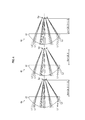
- Fig. 4 is an explanatory diagram for explaining the positioning control of the first lens group 22 shown in Fig. 3 by the positioning control unit 76.
- the positioning control unit 76 drives the lens moving system 32 to adjust the position of the first lens group 22 in the optical axis direction OA to the regular reflection position where the corneal reflection light L2 is the regular reflection light (the position where the incident angle of the illumination light L1 to the surface of the cornea Ea is set to the angle with which the corneal reflection light L2 is the regular reflection light). More specifically, on the basis of the statistical value of the brightness values of the corneal reflection image 60, the positioning control unit 76 adjusts the distance fb by moving the first lens group 22 by driving the lens moving system 32 so that the statistical value becomes within the threshold range.
- the positioning control unit 76 moves the first lens group 22 by the lens moving system 32 in the direction for making the distance fb larger as the case designated with the reference numeral 4a in Fig. 4.
- the positioning control unit 76 moves the first lens group 22 with the lens moving system 32 in the direction for making the distance fb smaller as the case designated with the reference numeral 4c in Fig. 4.
- the lens moving system 32 adjusts the position of the first lens group 22 (the lens barrel 30) in the optical axis direction OA in the present embodiment; however, not limited to this, the ophthalmologic device 10 as a whole or the measuring head containing the optical systems may be moved (positioned) in the optical axis direction OA. Further, instead of the lens moving system 32, a relative movement mechanism which relatively moves the first lens group 22 in the optical axis direction OA to the subject’s eye E by moving (positioning) the subject’s eye E (the supporting unit which supports the subject’s head), etc. in the optical axis direction OA may be provided.
- a known liquid lens which can be expanded or contracted by applying voltage may be used in the first lens group 22 (objective lens).
- a voltage control circuit which controls the voltage applied to the liquid lens is provided instead of the lens moving system 32.
- the incident angle of the illumination light L1 to the cornea Ea can be changed by expanding or contracting the liquid lens.
- the liquid lens and the voltage control circuit serve as the incident angle changing mechanism in the present invention.
- an interference figure (interference fringe) is generated on the corneal surface caused by reflection of the illumination light L1 on the outer and inner surfaces of the oily layer in the tear film.
- This interference figure has a color which corresponds to the thickness of the oily layer at each position on the corneal surface. Therefore, by determining the color of each position of the corneal reflection image 60 captured from the corneal reflection light L2 (the regular reflection light), the thickness of the tear film at each position on the corneal surface can be determined.
- the optical system control unit 72 serves as the imaging control unit in the present invention and starts operation of the illuminating optical system 14 and the measuring optical system 16 to perform the normal capturing of the corneal reflection image 60. More specifically, those prescribed conditions are such that the regular reflection determination unit 74 has determined that the corneal reflection light L2 is the regular reflection light, or that the positioning control unit 76 has completed the positioning control in the case where the regular reflection determination unit 74 has determined that the corneal reflection light L2 is not the regular reflection light. Then, the optical system control unit 72 outputs image data of the corneal reflection image 60 to the state determination unit 78 on the basis of the image signal outputted from the measuring optical system 16 by the normal capturing.
- the optical system control unit 72 may output to the state determination unit 78 the image data of the corneal reflection image 60 captured by the previous temporary capturing as the image data of the corneal reflection image 60 of the normal capturing, instead of causing the illuminating optical system 14 and the measuring optical system 16 carry out the normal capturing.
- the state determination unit 78 determines the thickness of the tear film (oily layer) at each position on the corneal surface by determining the color of the interference figure at each position of the corneal reflection image 60 on the basis of the image data of the corneal reflection image 60 inputted from the optical system control unit 72.
- the state determination unit 78 determines the temporal change in the thickness of the tear film as the state of the tear film. Furthermore, on the basis of the result of determination of the temporal change of the thickness of the tear film, the state determination unit 78 determines shape, forming position, and distribution of the forming positions, etc.
- the state of the tear film is not limited to the thickness of the tear film, the temporal change (change over time) of the thickness, and the dry spot (the shape, the forming position, and the distribution of the forming position), but covers the tear film break-up time (BUT), etc.
- the state determination unit 78 causes the results of the determination of the state of the tear film to be displayed on the monitor 66 and stored in the storage unit 68.
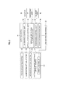
- FIG. 5 is a flowchart showing the flow of determination processing of the state of the tear film of the subject’s eye E with the ophthalmologic device 10 of the above-described configuration (corresponds to the method of operation of the ophthalmologic device in the present invention).
- the alignment control unit 70 of the control device 20 causes the light emitting unit 18a of the focus adjusting system 18 to emit the alignment determining light L3, and causes the light receiving unit 18b to ready for receiving the reflection light L4. Then, the alignment control unit 70 drives the lens moving system 32 to move the first lens group 22 back and forth along the optical axis direction OA. The alignment control unit 70 stops the back and forth movement of the first lens group 22 by the lens moving system 32 when the light receiving unit 18b receives the reflection light L4. Thus, the alignment of the first lens group 22 to the subject’s eye E in the optical axis direction OA is complete (Step S1).
- the optical system control unit 72 starts operation of the illumination light source 40 of the illuminating optical system 14 so as to irradiate the surface of the cornea Ea with the illumination light L1 by the illuminating optical system 14 through the first lens group 22, etc. (Step S2).
- This causes the corneal reflection light L2 of the illumination light L1 reflected on the surface of the cornea Ea to enter the measuring optical system 16 through the first lens group 22.
- the irradiation of the corneal surface with the illumination light L1 continues until the completion of the normal capturing of the corneal reflection image 60 in the present embodiment; however, the irradiation of the corneal surface with the illumination light L1 may be carried out only during the temporary capturing and the normal capturing of the corneal reflection image 60.
- the optical system control unit 72 starts operation of the interference figure imaging camera 56 of the measuring optical system 16 so as to carry out the temporary capturing of the corneal reflection light L2 by the interference figure imaging camera 56 (Step S3). Then, the interference figure imaging camera 56 outputs the image signal of the corneal reflection image 60 obtained by the temporary capturing of the corneal reflection light L2 to the regular reflection determination unit 74 of the control device 20.
- the regular reflection determination unit 74 calculates the statistical value of the brightness values of all or specific pixels of the corneal reflection image 60 on the basis of the obtained image signal, and determines whether the corneal reflection light L2 is the regular reflection light on the basis of whether the statistical value of the brightness values is within the threshold range (Step S4; corresponds to the determining step in the present invention).
- Step S5 If the regular reflection determination unit 74 determines that the corneal reflection light L2 is the regular reflection light (YES in Step S5), the process proceeds to Step S7 described later. To the contrary, if the regular reflection determination unit 74 determines that the corneal reflection light L2 is not the regular reflection light (NO in Step S5), the positioning control unit 76 starts operating.
- the positioning control unit 76 carries out the positioning control for moving the first lens group 22 to the regular reflection position by driving the lens moving system 32 according to the statistical value of the brightness values of the corneal reflection image 60 obtained by the temporary capturing, so that the statistical value is within the threshold range (Step S6; corresponds to the adjustment control step in the present invention).
- Step S6 corresponds to the adjustment control step in the present invention.
- Step S5 the optical system control unit 72 starts operation of the interference figure imaging camera 56 of the measuring optical system 16 to carry out the normal capturing of the corneal reflection light L2 which is the regular reflection light (Step S7; corresponds to the image-capturing control step in the present invention). Then, the interference figure imaging camera 56 outputs the image signal of the corneal reflection image 60 obtained by the normal capturing of the corneal reflection light L2 to the state determination unit 78.
- the state determination unit 78 determines the thickness, dry spot, etc. of the tear film, as the state of the tear film on the surface of the cornea Ea on the basis of the interference figure of the corneal reflection image 60 (Step S8; corresponds to the state determining step in the present invention). Then, the state determination unit 78 causes the result of the determination of the state of the tear film to be displayed on the monitor 66 and stored in the storage unit 68.
- the ophthalmologic device 10 of the present embodiment can reliably cause the illumination light L1 to be regularly reflected by the surface of the cornea Ea (i.e., the corneal reflection light L2 can be the regular reflection light), and thereby the normal capturing of the corneal reflection image 60 can be carried out in a state where the illumination light L1 and the corneal reflection light L2 reliably interfere with each other.
- the interference figure can be generated in the corneal reflection image 60 without fail, such that the state of the tear film on the corneal surface of the subject’s eye E can be determined regardless of the corneal shape of the subject’s eye E.
- the explanation is given using the focus adjusting system 18 which carries out the alignment of the first lens group 22 to the subject’s eye E in the optical axis direction OA by the optical-lever method as an example; however, the alignment method is not limited to the optical-lever method, and the alignment may be carried out with various alignment methods used for known ophthalmologic devices or known cameras such as an auto ref/keratometer, for example.
- the first lens group 22 is held in the lens barrel 30; however, the shape and configuration of the lens holding member (lens holding mechanism) which holds the first lens group 22 (namely, objective lens) are not specifically restricted.
- the lens moving system 32 adjusts the position of the first lens group 22 by moving the lens holding member along the optical axis direction OA.
- the configuration of various optical systems of the ophthalmologic device 10 are not restricted to the configurations shown in Fig. 1, and any configuration will do as far as it includes an optical system which irradiates the surface of the cornea Ea with the illumination light L1 through the objective lens, an optical system which captures the corneal reflection light L2 of the illumination light L1 incident through the objective lens, and a mechanism which carries out the positioning of the objective lens in the optical axis direction OA are provided, and moreover, configuration and placement of each optical system may be arbitrarily modified.
- ophthalmologic device 14 illuminating optical system 16: measuring optical system 18: focus adjusting system 20: control device 22: first lens group 30: lens barrel 40: illumination light source 56: interference figure imaging camera 60: corneal reflection image 70: alignment control unit 72: optical system control unit 74: regular reflection determination unit 76: positioning control unit 78: state determination unit
Landscapes
- Life Sciences & Earth Sciences (AREA)
- Health & Medical Sciences (AREA)
- Medical Informatics (AREA)
- Biophysics (AREA)
- Ophthalmology & Optometry (AREA)
- Engineering & Computer Science (AREA)
- Biomedical Technology (AREA)
- Heart & Thoracic Surgery (AREA)
- Physics & Mathematics (AREA)
- Molecular Biology (AREA)
- Surgery (AREA)
- Animal Behavior & Ethology (AREA)
- General Health & Medical Sciences (AREA)
- Public Health (AREA)
- Veterinary Medicine (AREA)
- Eye Examination Apparatus (AREA)
Abstract
Provided are an ophthalmologic device and a method of operation thereof which make it possible to correctly determine the state of the tear film on the corneal surface of the subject's eye regardless of the corneal shape of the subject's eye. The ophthalmologic device includes: an objective lens; an illuminating optical system configured to irradiate a cornea of a subject's eye with illumination light through the objective lens; an incident angle changing mechanism configured to change an incident angle of the illumination light incident to the cornea from the objective lens; an imaging optical system configured to output an image signal by capturing corneal reflection light of the illumination light entering through the objective lens; a regular reflection determination unit configured to, according to the image signal outputted from the imaging optical system, determine whether the corneal reflection light is regular reflection light that is regularly reflected by the cornea; an adjustment control unit configured to, when the regular reflection determination unit determines that the corneal reflection light is not the regular reflection light, adjust the incident angle to an angle at which the corneal reflection light is the regular reflection light by driving the incident angle changing mechanism according to the image signal; an imaging control unit configured to cause the imaging optical system to capture the regular reflection light; and a state determination unit configured to determine a state of a tear film of the subject's eye according to a corneal reflection image based on the image signal of the regular reflection light outputted from the imaging optical system.
Description
The present invention relates to an ophthalmologic device which is used for examining the state of the tear film of the subject’s eye and the method of operating the ophthalmologic device.
The number of patients who suffer with dry eye caused by working on VDT (visual display terminal), long-time using a smartphone, etc., or using contact lenses has been increasing in recent years. The human tear film is primarily constituted of an oily layer (also referred to as a lipid layer), a watery layer, and a mucus layer, from the outermost to the innermost. The outermost oily layer is secreted from the meibomian glands located in the inside of the eyelid, and covers the surface of the tear film to prevent the tears from evaporating. The watery layer is secreted from the lacrimal glands, moistens the surface of the cornea, and drains into the punctums. Dry eye occurs if the tears tend to dry up because the amount of oil secreted from the meibomian glands is reduced due to decrease in meibomian glands, or the amount of the tears (the watery layer) secreted from the lacrimal glands is reduced. Therefore, for diagnosing dry eye, it is necessary to observe change over time of the thickness of the tear film on the surface of the cornea (such as the breaking state of the tear film). Dry eye is a disorder in which the stability of the tear film is decreased because of various factors, and causes ocular discomfort, irregularity in visual performance, etc. and is sometimes accompanied by a failure in the surface of the eye (“Revision of the definition and diagnostic criteria of dry eye in Japan (Nihon no dry eye no teigi to shindankijun no kaitei)” (2016 Edition), page 2).
In the ophthalmologic devices disclosed in Patent Literature 1 and Patent Literature 2, in order to correctly determine the state of the tear film, it is necessary for the imaging optical system to capture the corneal reflection image produced by the corneal reflection light that is the illumination light having been regularly reflected by the corneal surface. Therefore, in the ophthalmologic device, the distance between the subject’s eye and the objective lens is appropriately adjusted by carrying out alignment, etc. so that the illumination light is regularly reflected by the corneal surface. However, in certain cases, the regular reflection does not occur on the corneal surface even if the distance between the subject’s eye and the objective lens is adjusted by means of, for example, the standard eye (reference eye), since the corneal shape (e.g., the radius of curvature of the cornea) of the subject’s eye differs for each subject. In these cases, a problem that the state of the tear film cannot be correctly determined occurs, since the illumination light and the corneal reflection light do not interfere (cannot be superimposed) with each other, and no interference figure is generated in the corneal reflection image.
The present invention has been contrived in view of these circumstances, an object thereof being to provide an ophthalmologic device which can correctly determine the state of the tear film on the corneal surface of the subject’s eye regardless of the corneal shape of the subject’s eye, and a method of operating the ophthalmologic device.
In order to attain the aforementioned object of the present invention, an ophthalmologic device includes: an objective lens; an illuminating optical system configured to irradiate a cornea of a subject’s eye with illumination light through the objective lens; an incident angle changing mechanism configured to change an incident angle of the illumination light incident to the cornea from the objective lens; an imaging optical system configured to output an image signal by capturing corneal reflection light of the illumination light entering through the objective lens; a regular reflection determination unit configured to, according to the image signal outputted from the imaging optical system, determine whether the corneal reflection light is regular reflection light that is regularly reflected by the cornea; an adjustment control unit configured to, when the regular reflection determination unit determines that the corneal reflection light is not the regular reflection light, adjust the incident angle to an angle at which the corneal reflection light is the regular reflection light by driving the incident angle changing mechanism according to the image signal; an imaging control unit configured to cause the imaging optical system to capture the regular reflection light; and a state determination unit configured to determine a state of a tear film of the subject’s eye according to a corneal reflection image based on the image signal of the regular reflection light outputted from the imaging optical system.
The ophthalmologic device makes it possible, regardless of the corneal shape of the subject’s eye, to obtain the illumination light having been regularly reflected by the corneal surface, in other words, the corneal reflection light can be made the regular reflection light of the illumination light.
In an ophthalmologic device according to another embodiment of the present invention, the regular reflection determination unit is configured to, according to a brightness value of the corneal reflection image based on the image signal, determine whether the corneal reflection light is the regular reflection light; and the adjustment control unit is configured to adjust the incident angle according to the brightness value of the corneal reflection image. This makes it possible to have the corneal reflection light be the regular reflection light of the illumination light regardless of the corneal shape of the subject’s eye.
In an ophthalmologic device according to another embodiment of the present invention, the incident angle changing mechanism includes a relative movement mechanism configured to cause the objective lens to move relatively to the subject’s eye in an optical axis direction of the objective lens; and the adjustment control unit is configured to, according to the image signal, carry out positioning of the objective lens to a regular reflection position where the corneal reflection light is the regular reflection light by driving the relative movement mechanism. This makes it possible to have the reflection light be the regular reflection light of the illumination light regardless of the corneal shape of the subject’s eye.
An ophthalmologic device according to another embodiment of the present invention further includes: an alignment determination unit configured to determine alignment of the objective lens to the subject’s eye in the optical axis direction; and an alignment control unit configured to adjust the alignment of the objective lens in the optical axis direction by driving the relative movement mechanism according to a result of determination by the alignment determination unit, wherein the regular reflection determination unit is configured to carry out the determination according to the image signal outputted from the imaging optical system in a state where the alignment of the objective lens is completed. Even in a case where the illumination light is not regularly reflected by the corneal surface after the alignment due to the corneal shape of the subject’s eye, the corneal reflection light can be the regular reflection light of the illumination light.
In an ophthalmologic device according to another embodiment of the present invention, the state determination unit is configured to determine an interference figure generated on a surface of the cornea from the corneal reflection image, and to determine a thickness of the tear film as the state of the tear film according to the interference figure.
In order to attain the aforementioned object of the present invention, a method of operating an ophthalmologic device comprising an objective lens, an illuminating optical system configured to irradiate a cornea of a subject’s eye with illumination light through the objective lens, an incident angle changing mechanism configured to change an incident angle of the illumination light incident to the cornea from the objective lens, an imaging optical system configured to output an image signal by capturing corneal reflection light of the illumination light entering through the objective lens, the method includes: a regular reflection determining step of, according to the image signal outputted from the imaging optical system, determining whether the corneal reflection light is regular reflection light that is regularly reflected by the cornea; an adjustment control step of, when the corneal reflection light is not determined as the regular reflection light in the regular reflection determining step, adjusting the incident angle to an angle at which the corneal reflection light is the regular reflection light by driving the incident angle changing mechanism according to the image signal; an imaging control step of causing the imaging optical system to capture the regular reflection light; and a state determining step of determining a state of a tear film of the subject’s eye according to a corneal reflection image based on the image signal of the regular reflection light outputted from the imaging optical system.
According to the present invention, it is possible to correctly determine the state of the tear film on the corneal surface of the subject’s eye regardless of the corneal shape of the subject’s eye.
Configuration of the ophthalmologic device
Fig. 1 is a schematic diagram of optical systems of anophthalmologic device 10. As shown in Fig. 1, the ophthalmologic device 10 includes an anterior segment observing optical system 12, an illuminating optical system 14, a measuring optical system 16 serving as the imaging optical system in the present invention, a focus adjusting system 18, and a control device 20.
Fig. 1 is a schematic diagram of optical systems of an
The anterior segment observing optical system 12 includes a first lens group 22 serving as the objective lens in the present invention. The anterior segment observing optical system 12 further includes a first semireflecting mirror 24, a lens 26, and an anterior segment camera 28, which are arranged along the optical axis direction OA of the first lens group 22.
The first lens group 22 is a so-called objective lens and is placed in a lens barrel 30. The objective lens (the first lens group 22) includes a plurality of lenses in the present embodiment; however, the objective lens may consist of a single lens. The first lens group 22 irradiates the surface of the cornea Ea of the subject’s eye E with the illumination light L1 incident from the first semireflecting mirror 24. The corneal reflection light L2, which is the illumination light L1 having been reflected by the corneal surface, is incident to the first lens group 22. The corneal reflection light L2 is then incident on the first semireflecting mirror 24 through the first lens group 22.
The lens barrel 30 is moved by a lens moving system 32 along the optical axis direction OA of the first lens group 22. The lens moving system 32 is driven under control by the control device 20, which is described later.
The lens moving system 32 serves as the relative movement mechanism and the incident angle changing mechanism in the present invention. Although not shown in the drawings, the lens moving system 32 includes a sliding mechanism configured to hold the lens barrel 30 to be slidable parallelly to the optical axis direction OA, and a driving mechanism such as a motor, etc. configured to move the lens barrel 30 back and forth parallelly to the optical axis direction OA. The lens moving system 32 can move the first lens group 32 in the optical axis direction OA relatively to the subject’s eye E by moving the lens barrel 30 in the optical axis direction OA. Thereby, the incident angle of the illumination light L1 to the surface of the cornea Ea can be changed as described in detail later with reference to Figs. 3 and 4. The lens moving system 32 is not limited to the motor-driven mechanism, and various driving mechanisms other than motor, such as a solenoid for example, may be used as far as the lens barrel 30 can be moved parallelly to the optical axis direction OA.
The first semireflecting mirror 24 reflects a part of the illumination light L1 incident from the illuminating optical system 14, which is described later, toward the first lens group 22. The first semireflecting mirror 24 transmits a part of the corneal reflection light L2 incident from the first lens group 22 to the lens 26, and reflects the rest of the corneal reflection light L2 toward a second lens group 50 described later.
The lens 26 transmits the corneal reflection light L2 incident from the first semireflecting mirror 24 to the anterior segment camera 28. The anterior segment camera 28 includes a CMOS (complementary metal oxide semiconductor) or CCD (charge-coupled device) type imaging element, and captures an observation image of the anterior segment of the subject’s eye E (hereinafter referred to as the “anterior segment observation image”) produced by the corneal reflection light L2 incident from the lens 26, and outputs the image signal of the anterior segment observation image to the control device 20 described later.
The illuminating optical system 14 forms a light path which branches off from the anterior segment observing optical system 12 through the first semireflecting mirror 24.
The illuminating optical system 14 includes an illumination light source 40. The illuminating optical system 14 further includes a lens 42, a variable filter 44, a second semireflecting mirror 46, a mirror 48, and a second lens group 50, which are arranged along the light path OB of the illumination light L1 emitted from the illumination light source 40. The illuminating optical system 14 shares the first semireflecting mirror 24 and the first lens group 22 with the anterior segment observing optical system 12.
The illumination light source 40 emits white light as the illumination light L1 toward the lens 42, and includes a known light source such as an LED (light emitting diode), a halogen lamp, etc. emitting white light. The lens 42 transmits the illumination light L1 incident from the illumination light source 40 to the variable filter 44. The variable filter 44 transmits the illumination light L1 incident from the lens 42 to the second semireflecting mirror 46 while adjusting the amount of the illumination light L1 incident to the second semireflecting mirror 46.
The second semireflecting mirror 46 transmits a part of the illumination light L1 incident from the variable filter 44 to the mirror 48, and reflects a part of the corneal reflection light L2 incident from the second lens group 50, which is described later, toward the measuring optical system 16.
The mirror 48 and the second lens group 50 transmit the illumination light L1 incident from the second semireflecting mirror 46 to the first semireflecting mirror 24, and transmit the corneal reflection light L2 incident from the first semireflecting mirror 24 to the second semireflecting mirror 46.
The illumination light L1 emitted from the illumination light source 40 passes through the lens 42 to the first semireflecting mirror 24, and is incident to the surface of the cornea Ea through the first lens group 22. This causes the corneal reflection light L2, which is the illumination light L1 having been incident to and reflected by the corneal surface, to be incident to the first lens group 22.
The measuring optical system 16 forms a light path which branches off from the illuminating optical system 14 through the second semireflecting mirror 46. The measuring optical system 16 includes a diaphragm 52, a lens 54 and an interference figure imaging camera 56, and shares a section from the first lens group 22 to the second semireflecting mirror 46 with the illuminating optical system 14.
The diaphragm 52 and the lens 54 transmit the corneal reflection light L2 incident from the second semireflecting mirror 46 to the interference figure imaging camera 56.
The interference figure imaging camera 56 includes a CMOS or CCD type imaging element, and captures a corneal reflection image 60 produced by the corneal reflection light L2 incident from the lens 54, and outputs the image signal of the corneal reflection image 60 to the control device 20.
The focus adjusting system 18 serves as the alignment determination unit in the present invention, and is used for positioning (alignment) of the first lens group 22 in the optical axis direction OA of the subject’s eye E using the optical-lever method. The focus adjusting system 18 includes a light emitting unit 18a and a light receiving unit 18b arranged in the circumference of the lens barrel 30. The light emitting unit 18a and the light receiving unit 18b move together with the first lens group 22 and the lens barrel 30 along the optical axis direction OA.
The light emitting unit 18a emits alignment determining light L3 that is incident to the surface of the cornea Ea from an oblique direction. When the first lens group 22 is aligned to the subject’s eye E, the light receiving unit 18b receives the reflection light L4 that is the alignment determining light L3 having been reflected by the corneal surface. Thus, it can be determined whether the first lens group 22 is aligned to the subject’s eye E on the basis of whether the light receiving unit 18b is receiving the reflection light L4. The light receiving unit 18b outputs a light receiving signal of the reflection light L4 to the control device 20. The light emitting unit 18a and the light receiving unit 18b of the focus adjusting system 18 may be placed in the periphery of the lens 26 after the first semireflecting mirror 24, and cause the alignment determining light L3 and the reflection light L4 to pass through the first lens group 22.
Fig. 2 is a functional block diagram of the control device 20. As shown in Fig. 2, the control device 20 totally controls the action of each unit of the ophthalmologic device 10. The control device 20 is an arithmetic circuit including various processors, memories, etc. The various processors include a CPU (Central Processing Unit), a GPU (Graphics Processing Unit), an ASIC (Application Specific Integrated Circuit), and a programmable logical device (for example, SPLD (Simple Programmable Logic Devices), CPLD (Complex Programmable Logic Device), FPGA (Field Programmable Gate Arrays)), etc. The various functions of the control device 20 may be realized by a single processor, or by multiple processors of the same or different types.
The control device 20 is connected with the above-described anterior segment observing optical system 12, illuminating optical system 14, measuring optical system 16, focus adjusting system 18 and lens moving system 32, and further with an operating unit 64, a monitor 66, and a memory unit 68.
The operating unit 64 includes, for example, a keyboard, a mouse, operating switches, etc. and accepts various operations (such as measurement start operation and setting input operation) by the test staff. The monitor 66 includes, for example, a known LCD monitor, and displays the result of examination of the tear film of the subject’s eye E, the anterior segment observation image captured by the anterior segment observing optical system 12, and a screen for displaying various setting of the ophthalmologic device 10, etc. The memory unit 68 stores the control program for operation of the ophthalmologic device 10, the results of examination of the tear film of the subject’s eye E, etc.
The control device 20 functions as an alignment control unit 70, an optical system control unit 72, a regular reflection determination unit 74, a positioning control unit 76, and a state determination unit 78 by running the control program stored in the storage unit 68. Hereinafter, in the present embodiment, any part mentioned as a “… unit” may be a “… circuit”, a “… equipment” or a “… device”. Any part mentioned as a “… unit” may be composed of any of firmware, software, hardware, or combination thereof.
The alignment control unit 70 carries out alignment adjustment for the first lens group 22 to the subject’s eye E in the optical axis direction OA by driving the lens moving system 32 on the basis of the light receiving signal inputted from the light receiving unit 18b, before the start of examination with the ophthalmologic device 10.
More specifically, to determine the alignment, the alignment control unit 70 starts operation of the light emitting unit 18a and the light receiving unit 18b of the focus adjusting system 18, and moves the first lens group 22 back and forth along the optical axis direction OA by driving the lens moving system 32. Then, when the reflection light L4 is received by the light receiving unit 18b during the back and forth movement of the first lens group 22, the alignment control unit 70 stops the back and forth movement of the first lens group 22 by the lens moving system 32. Thereby, the first lens group 22 can be settled at the position where the reflection light L4 is received by the light receiving unit 18b, that is, the position where the first lens group 22 is aligned to the subject’s eye E.
The optical system control unit 72 controls the operations of the anterior segment observing optical system 12, the illuminating optical system 14, and the measuring optical system 16, namely, capture of the anterior segment observation image by the anterior segment observing optical system 12, emission of the illumination light L1 by the illumination light source 40, and capture of the corneal reflection image 60 by the interference figure imaging camera 56.
After completion of the alignment by the alignment control unit 70, the optical system control unit 72 causes the illuminating optical system 14 and the measuring optical system 16 to perform temporary (provisional) capturing of the corneal reflection image 60, and when the prescribed condition described below is satisfied, causes the measuring optical system 16, etc. to perform normal (non-provisional) capturing of the corneal reflection image 60.
The corneal reflection image 60 obtained by the temporary capturing is used for determining whether the illumination light L1 is regularly reflected by the surface of the cornea Ea, that is, whether the corneal reflection light L2 is the regular reflection light of the illumination light L1 (whether it is the regular reflection in which the angle of incidence of the illumination light L1 to the cornea surface is equal to the angle of reflection of the corneal reflection light L2 from the cornea surface) as explained in detail below.
The corneal reflection image 60 obtained by the normal capturing is used for determining the state of the tear film of the subject’s eye E. Here, the tear film may mean each of the oily layer (lipid layer), the watery layer and the mucus layer, or a film composed of two or more of these layers.
The regular reflection determination unit 74 determines whether the corneal reflection light L2 is the regular reflection light of the illumination light L1 having been regularly reflected by the surface of the cornea Ea. The regular reflection here means that the light flux of the illumination light L1 is reflected back to the emission region where the illumination light L1 is emitted from the first lens group 22 (limited to the same position). Accordingly, the corneal reflection light L2 (the regular reflection light) that is the illumination light L1 having been emitted from an arbitrary region of the first lens group 22 and regularly reflected by the corneal surface is incident to the original region. That is, the emission region of the illumination light L1 in the first lens group 22 coincides (or substantially coincides) with the incident region where the corneal reflection light L2 that is the regular reflection light of the illumination light L1 is incident to the first lens group 22. An example of the regular reflection light includes the perpendicularly reflected light that is the illumination light L1 perpendicularly incident to the corneal surface and perpendicularly reflected by the corneal surface; however, the regular reflection light is not limited to the perpendicularly reflected light.
Fig. 3 is an explanatory diagram for explaining examples of the cases where the illumination light L1 is not regularly reflected by the surface of the cornea Ea (the case in which the corneal reflection light L2 is not the regular reflection light). As shown in Fig. 3, the distance fb between the subject’s eye E (the cornea Ea) and the first lens group 22 after completion of the alignment by the alignment control unit 70 is designed in accordance with the standard eye, in which the radius of curvature of the cornea Ea is R = 7.7 mm (including about 7.7 mm). The distance fb is 24.0 mm, for example, in the present embodiment.
In the present embodiment, the radius of curvature of the cornea Ea of the standard eye is set to R = 7.7 mm; however, this value is an example, and the radius of curvature may be larger or smaller than 7.7 mm.
In the case designated with the reference numeral 3b in Fig. 3 where the radius of curvature of the cornea Ea of the subject’s eye E is around R = 7.7 mm, the illumination light L1 is regularly reflected by the surface of the cornea Ea, and thus, the corneal reflection light L2 is the regular reflection light of the illumination light L1.
On the other hand, in the case designated with the reference numeral 3a in Fig. 3, for example, where the radius of curvature of the cornea Ea of the subject’s eye E is R = 6.7 mm, which is smaller than the standard value, the illumination light L1 is not regularly reflected by the surface of the cornea Ea with the distance fb (24.0 mm), which corresponds to the radius of curvature of R = 7.7 mm, and thus, the corneal reflection light L2 is not the regular reflection light.
Similarly, in the case designated with the reference numeral 3c in Fig. 3, for example, where the radius of curvature of the cornea Ea of the subject’s eye E is R = 8.7 mm, which is larger than the standard value, the illumination light L1 is not regularly reflected by the surface of the cornea Ea with the distance fb (24.0 mm), which corresponds to the radius of curvature of R = 7.7 mm, and thereby, the corneal reflection light L2 is not the regular reflection light. In the present embodiment, R = 6.7 mm and R = 8.7 mm are shown as examples of the radius of curvature of the cornea Ea in the case where the corneal reflection light L2 is not the regular reflection light; however, those values are also examples, and they may be other values.
In the present embodiment, the regular reflection determination unit 74 determines whether the corneal reflection light L2 is the regular reflection light of the illumination light L1, and if the regular reflection determination unit 74 determines that the corneal reflection light L2 is not the regular reflection light of the illumination light L1, the distance fb is adjusted with the positioning control unit 76 described below so that the corneal reflection light L2 is the regular reflection light of the illumination light L1.
More specifically, the regular reflection determination unit 74 obtains the image signal of the corneal reflection image 60 obtained by the temporary capturing from the measuring optical system 16 (the interference figure imaging camera 56), and calculates the statistical value (mean value, maximum value, minimum value, and additional value) of the brightness values on the basis of the brightness values (pixel values) of all or specific pixels of the corneal reflection image 60 based on the image signal. The statistical value of the brightness values is used as an index that indicates the amount of light of the corneal reflection light L2 (the corneal reflection image 60). The regular reflection determination unit 74 determines whether the corneal reflection light L2 is the regular reflection light on the basis of whether the statistical value of the brightness values is within a prescribed range of the lower limit and the upper limit (hereinafter referred to as the threshold range).
For example, in the case designated with the reference numeral 3a in Fig. 3 where the radius of curvature of the cornea Ea is R = 6.7 mm, a part of the corneal reflection light L2 is not captured by the measuring optical system 16, and the statistical value of the brightness values thereby becomes smaller than the prescribed lower limit value. On the other hand, in the case designated with the reference numeral 3c in Fig. 3 where the radius of curvature of the cornea Ea is R = 8.7 mm, the amount of the corneal reflection light L2 captured by the measuring optical system 16 is larger than that in the case designated with the reference numeral 3b (R = 7.7 mm), and the statistical value of the brightness values thereby becomes larger than the prescribed upper limit.
Accordingly, the regular reflection determination unit 74 determines whether the corneal reflection light L2 is the regular reflection light of the illumination light L1 on the basis of whether the calculated statistical value of the brightness values of the corneal reflection image 60 is within the threshold range. Then, the regular reflection determination unit 74 outputs the result of the determination to the positioning control unit 76.
Fig. 4 is an explanatory diagram for explaining the positioning control of the first lens group 22 shown in Fig. 3 by the positioning control unit 76. In Fig. 4, the positioning is carried out for the first lens group 22 in the case designated with the reference numeral 4a where the radius of curvature of the cornea Ea is R = 6.7 mm, and for the first lens group 22 in the case designated with the reference numeral 4c where the radius of curvature of the cornea Ea is R = 8.7 mm.
As shown in Fig. 4 as well as Figs. 2 and 3, if the regular reflection determination unit 74 determines that the corneal reflection light L2 is not the regular reflection light of the illumination light L1, the positioning control unit 76 drives the lens moving system 32 to adjust the position of the first lens group 22 in the optical axis direction OA to the regular reflection position where the corneal reflection light L2 is the regular reflection light (the position where the incident angle of the illumination light L1 to the surface of the cornea Ea is set to the angle with which the corneal reflection light L2 is the regular reflection light). More specifically, on the basis of the statistical value of the brightness values of the corneal reflection image 60, the positioning control unit 76 adjusts the distance fb by moving the first lens group 22 by driving the lens moving system 32 so that the statistical value becomes within the threshold range.
For example, when the statistical value of the brightness values is smaller than the lower limit of the threshold range as the case designated with the reference numeral 3a in Fig. 3, the positioning control unit 76 moves the first lens group 22 by the lens moving system 32 in the direction for making the distance fb larger as the case designated with the reference numeral 4a in Fig. 4. When the statistical value of the brightness values is larger than the upper limit of the threshold range as the case designated with the reference numeral 3c in Fig. 3, the positioning control unit 76 moves the first lens group 22 with the lens moving system 32 in the direction for making the distance fb smaller as the case designated with the reference numeral 4c in Fig. 4. Thus, the position of the first lens group 22 in the optical axis direction OA (the incident angle of the illumination light L1 to the cornea Ea) can be adjusted so that the corneal reflection light L2 is the regular reflection light of the illumination light L1.
The lens moving system 32 adjusts the position of the first lens group 22 (the lens barrel 30) in the optical axis direction OA in the present embodiment; however, not limited to this, the ophthalmologic device 10 as a whole or the measuring head containing the optical systems may be moved (positioned) in the optical axis direction OA. Further, instead of the lens moving system 32, a relative movement mechanism which relatively moves the first lens group 22 in the optical axis direction OA to the subject’s eye E by moving (positioning) the subject’s eye E (the supporting unit which supports the subject’s head), etc. in the optical axis direction OA may be provided.
Furthermore, a known liquid lens which can be expanded or contracted by applying voltage may be used in the first lens group 22 (objective lens). In this case, a voltage control circuit which controls the voltage applied to the liquid lens is provided instead of the lens moving system 32. The incident angle of the illumination light L1 to the cornea Ea can be changed by expanding or contracting the liquid lens. Thus, it is possible to cause the illumination light L1 to be regularly reflected by the surface of the cornea Ea, namely, the corneal reflection light L2 to be the regular reflection light, by adjusting the amount of expansion and contraction of the liquid lens. In this case, the liquid lens and the voltage control circuit serve as the incident angle changing mechanism in the present invention.
When the illumination light L1 is incident to the corneal surface, an interference figure (interference fringe) is generated on the corneal surface caused by reflection of the illumination light L1 on the outer and inner surfaces of the oily layer in the tear film. This interference figure has a color which corresponds to the thickness of the oily layer at each position on the corneal surface. Therefore, by determining the color of each position of the corneal reflection image 60 captured from the corneal reflection light L2 (the regular reflection light), the thickness of the tear film at each position on the corneal surface can be determined.
Returning to Fig. 2, when the prescribed conditions under which the corneal reflection light L2 is the regular reflection light are satisfied, the optical system control unit 72 serves as the imaging control unit in the present invention and starts operation of the illuminating optical system 14 and the measuring optical system 16 to perform the normal capturing of the corneal reflection image 60. More specifically, those prescribed conditions are such that the regular reflection determination unit 74 has determined that the corneal reflection light L2 is the regular reflection light, or that the positioning control unit 76 has completed the positioning control in the case where the regular reflection determination unit 74 has determined that the corneal reflection light L2 is not the regular reflection light. Then, the optical system control unit 72 outputs image data of the corneal reflection image 60 to the state determination unit 78 on the basis of the image signal outputted from the measuring optical system 16 by the normal capturing.
In the case where the regular reflection determination unit 74 has determined that the corneal reflection light L2 is the regular reflection light, the optical system control unit 72 may output to the state determination unit 78 the image data of the corneal reflection image 60 captured by the previous temporary capturing as the image data of the corneal reflection image 60 of the normal capturing, instead of causing the illuminating optical system 14 and the measuring optical system 16 carry out the normal capturing.
The state determination unit 78 determines the thickness of the tear film (oily layer) at each position on the corneal surface by determining the color of the interference figure at each position of the corneal reflection image 60 on the basis of the image data of the corneal reflection image 60 inputted from the optical system control unit 72. When a series of normal capturing of the corneal reflection image 60 is carried out in succession under control by the optical system control unit 72, the state determination unit 78 determines the temporal change in the thickness of the tear film as the state of the tear film. Furthermore, on the basis of the result of determination of the temporal change of the thickness of the tear film, the state determination unit 78 determines shape, forming position, and distribution of the forming positions, etc. of the dry spot which is the region where the tear film has been broken on the corneal surface as the state of the tear film. Since the method for determining the state of the tear film from the corneal reflection image 60 is well known art, no specific explanation is given here. The state of the tear film is not limited to the thickness of the tear film, the temporal change (change over time) of the thickness, and the dry spot (the shape, the forming position, and the distribution of the forming position), but covers the tear film break-up time (BUT), etc.
The state determination unit 78 causes the results of the determination of the state of the tear film to be displayed on the monitor 66 and stored in the storage unit 68.
Operation of the ophthalmologic device
Fig. 5 is a flowchart showing the flow of determination processing of the state of the tear film of the subject’s eye E with theophthalmologic device 10 of the above-described configuration (corresponds to the method of operation of the ophthalmologic device in the present invention).
Fig. 5 is a flowchart showing the flow of determination processing of the state of the tear film of the subject’s eye E with the
As shown in Fig. 5, if the subject’s eye E is positioned in front of the first lens group 22, the alignment control unit 70 of the control device 20 causes the light emitting unit 18a of the focus adjusting system 18 to emit the alignment determining light L3, and causes the light receiving unit 18b to ready for receiving the reflection light L4. Then, the alignment control unit 70 drives the lens moving system 32 to move the first lens group 22 back and forth along the optical axis direction OA. The alignment control unit 70 stops the back and forth movement of the first lens group 22 by the lens moving system 32 when the light receiving unit 18b receives the reflection light L4. Thus, the alignment of the first lens group 22 to the subject’s eye E in the optical axis direction OA is complete (Step S1).
Upon completion of the alignment, the optical system control unit 72 starts operation of the illumination light source 40 of the illuminating optical system 14 so as to irradiate the surface of the cornea Ea with the illumination light L1 by the illuminating optical system 14 through the first lens group 22, etc. (Step S2). This causes the corneal reflection light L2 of the illumination light L1 reflected on the surface of the cornea Ea to enter the measuring optical system 16 through the first lens group 22. The irradiation of the corneal surface with the illumination light L1 continues until the completion of the normal capturing of the corneal reflection image 60 in the present embodiment; however, the irradiation of the corneal surface with the illumination light L1 may be carried out only during the temporary capturing and the normal capturing of the corneal reflection image 60.
Thereafter, the optical system control unit 72 starts operation of the interference figure imaging camera 56 of the measuring optical system 16 so as to carry out the temporary capturing of the corneal reflection light L2 by the interference figure imaging camera 56 (Step S3). Then, the interference figure imaging camera 56 outputs the image signal of the corneal reflection image 60 obtained by the temporary capturing of the corneal reflection light L2 to the regular reflection determination unit 74 of the control device 20.
Upon obtaining the image signal of the corneal reflection image 60 from the measuring optical system 16, the regular reflection determination unit 74 calculates the statistical value of the brightness values of all or specific pixels of the corneal reflection image 60 on the basis of the obtained image signal, and determines whether the corneal reflection light L2 is the regular reflection light on the basis of whether the statistical value of the brightness values is within the threshold range (Step S4; corresponds to the determining step in the present invention).
If the regular reflection determination unit 74 determines that the corneal reflection light L2 is the regular reflection light (YES in Step S5), the process proceeds to Step S7 described later. To the contrary, if the regular reflection determination unit 74 determines that the corneal reflection light L2 is not the regular reflection light (NO in Step S5), the positioning control unit 76 starts operating.
The positioning control unit 76 carries out the positioning control for moving the first lens group 22 to the regular reflection position by driving the lens moving system 32 according to the statistical value of the brightness values of the corneal reflection image 60 obtained by the temporary capturing, so that the statistical value is within the threshold range (Step S6; corresponds to the adjustment control step in the present invention). Thereby, as described with reference to Fig. 4, the position of the first lens group 22 (the incident angle of the illumination light L1 to the surface of the cornea Ea) is adjusted such that the corneal reflection light L2 is the regular reflection light of the illumination light L1.
If the positioning control by the positioning control unit 76 is completed, or if it is determined as YES in Step S5, the optical system control unit 72 starts operation of the interference figure imaging camera 56 of the measuring optical system 16 to carry out the normal capturing of the corneal reflection light L2 which is the regular reflection light (Step S7; corresponds to the image-capturing control step in the present invention). Then, the interference figure imaging camera 56 outputs the image signal of the corneal reflection image 60 obtained by the normal capturing of the corneal reflection light L2 to the state determination unit 78.
Upon obtaining the image signal of the corneal reflection image 60 from the measuring optical system 16, the state determination unit 78 determines the thickness, dry spot, etc. of the tear film, as the state of the tear film on the surface of the cornea Ea on the basis of the interference figure of the corneal reflection image 60 (Step S8; corresponds to the state determining step in the present invention). Then, the state determination unit 78 causes the result of the determination of the state of the tear film to be displayed on the monitor 66 and stored in the storage unit 68.
Effects of the present embodiment
As described above, even when the corneal shape of the subject’s eye E is different from that of the standard eye, theophthalmologic device 10 of the present embodiment can reliably cause the illumination light L1 to be regularly reflected by the surface of the cornea Ea (i.e., the corneal reflection light L2 can be the regular reflection light), and thereby the normal capturing of the corneal reflection image 60 can be carried out in a state where the illumination light L1 and the corneal reflection light L2 reliably interfere with each other. Thus, the interference figure can be generated in the corneal reflection image 60 without fail, such that the state of the tear film on the corneal surface of the subject’s eye E can be determined regardless of the corneal shape of the subject’s eye E.
As described above, even when the corneal shape of the subject’s eye E is different from that of the standard eye, the
Modifications
In the above-described embodiment, the explanation is given using thefocus adjusting system 18 which carries out the alignment of the first lens group 22 to the subject’s eye E in the optical axis direction OA by the optical-lever method as an example; however, the alignment method is not limited to the optical-lever method, and the alignment may be carried out with various alignment methods used for known ophthalmologic devices or known cameras such as an auto ref/keratometer, for example.
In the above-described embodiment, the explanation is given using the
In the above-described embodiment, the first lens group 22 is held in the lens barrel 30; however, the shape and configuration of the lens holding member (lens holding mechanism) which holds the first lens group 22 (namely, objective lens) are not specifically restricted. In this case, the lens moving system 32 adjusts the position of the first lens group 22 by moving the lens holding member along the optical axis direction OA.
The configuration of various optical systems of the ophthalmologic device 10 are not restricted to the configurations shown in Fig. 1, and any configuration will do as far as it includes an optical system which irradiates the surface of the cornea Ea with the illumination light L1 through the objective lens, an optical system which captures the corneal reflection light L2 of the illumination light L1 incident through the objective lens, and a mechanism which carries out the positioning of the objective lens in the optical axis direction OA are provided, and moreover, configuration and placement of each optical system may be arbitrarily modified.
10: ophthalmologic device
14: illuminating optical system
16: measuring optical system
18: focus adjusting system
20: control device
22: first lens group
30: lens barrel
40: illumination light source
56: interference figure imaging camera
60: corneal reflection image
70: alignment control unit
72: optical system control unit
74: regular reflection determination unit
76: positioning control unit
78: state determination unit
14: illuminating optical system
16: measuring optical system
18: focus adjusting system
20: control device
22: first lens group
30: lens barrel
40: illumination light source
56: interference figure imaging camera
60: corneal reflection image
70: alignment control unit
72: optical system control unit
74: regular reflection determination unit
76: positioning control unit
78: state determination unit
Claims (6)
- An ophthalmologic device, comprising:
an objective lens;
an illuminating optical system configured to irradiate a cornea of a subject’s eye with illumination light through the objective lens;
an incident angle changing mechanism configured to change an incident angle of the illumination light incident to the cornea from the objective lens;
an imaging optical system configured to output an image signal by capturing corneal reflection light of the illumination light entering through the objective lens;
a regular reflection determination unit configured to, according to the image signal outputted from the imaging optical system, determine whether the corneal reflection light is regular reflection light that is regularly reflected by the cornea;
an adjustment control unit configured to, when the regular reflection determination unit determines that the corneal reflection light is not the regular reflection light, adjust the incident angle to an angle at which the corneal reflection light is the regular reflection light by driving the incident angle changing mechanism according to the image signal;
an imaging control unit configured to cause the imaging optical system to capture the regular reflection light; and
a state determination unit configured to determine a state of a tear film of the subject’s eye according to a corneal reflection image based on the image signal of the regular reflection light outputted from the imaging optical system. - The ophthalmologic device as defined in claim 1, wherein:
the regular reflection determination unit is configured to, according to a brightness value of the corneal reflection image based on the image signal, determine whether the corneal reflection light is the regular reflection light; and
the adjustment control unit is configured to adjust the incident angle according to the brightness value of the corneal reflection image. - The ophthalmologic device as defined in claim 1 or 2, wherein:
the incident angle changing mechanism includes a relative movement mechanism configured to cause the objective lens to move relatively to the subject’s eye in an optical axis direction of the objective lens; and
the adjustment control unit is configured to, according to the image signal, carry out positioning of the objective lens to a regular reflection position where the corneal reflection light is the regular reflection light by driving the relative movement mechanism. - The ophthalmologic device as defined in claim 3, further comprising:
an alignment determination unit configured to determine alignment of the objective lens to the subject’s eye in the optical axis direction; and
an alignment control unit configured to adjust the alignment of the objective lens in the optical axis direction by driving the relative movement mechanism according to a result of determination by the alignment determination unit,
wherein the regular reflection determination unit is configured to carry out the determination according to the image signal outputted from the imaging optical system in a state where the alignment of the objective lens is completed. - The ophthalmologic device as defined in any one of claims 1 to 4, wherein the state determination unit is configured to determine an interference figure generated on a surface of the cornea from the corneal reflection image, and to determine a thickness of the tear film as the state of the tear film according to the interference figure.
- A method of operating an ophthalmologic device comprising an objective lens, an illuminating optical system configured to irradiate a cornea of a subject’s eye with illumination light through the objective lens, an incident angle changing mechanism configured to change an incident angle of the illumination light incident to the cornea from the objective lens, an imaging optical system configured to output an image signal by capturing corneal reflection light of the illumination light entering through the objective lens, the method comprising:
a regular reflection determining step of, according to the image signal outputted from the imaging optical system, determining whether the corneal reflection light is regular reflection light that is regularly reflected by the cornea;
an adjustment control step of, when the corneal reflection light is not determined as the regular reflection light in the regular reflection determining step, adjusting the incident angle to an angle at which the corneal reflection light is the regular reflection light by driving the incident angle changing mechanism according to the image signal;
an imaging control step of causing the imaging optical system to capture the regular reflection light; and
a state determining step of determining a state of a tear film of the subject’s eye according to a corneal reflection image based on the image signal of the regular reflection light outputted from the imaging optical system.
Applications Claiming Priority (2)
| Application Number | Priority Date | Filing Date | Title |
|---|---|---|---|
| US201862741293P | 2018-10-04 | 2018-10-04 | |
| US62/741,293 | 2018-10-04 |
Publications (1)
| Publication Number | Publication Date |
|---|---|
| WO2020071140A1 true WO2020071140A1 (en) | 2020-04-09 |
Family
ID=70055894
Family Applications (1)
| Application Number | Title | Priority Date | Filing Date |
|---|---|---|---|
| PCT/JP2019/036764 Ceased WO2020071140A1 (en) | 2018-10-04 | 2019-09-19 | Ophthalmologic device and method of operating ophthalmologic device |
Country Status (1)
| Country | Link |
|---|---|
| WO (1) | WO2020071140A1 (en) |
Citations (10)
| Publication number | Priority date | Publication date | Assignee | Title |
|---|---|---|---|---|
| JPS5611802U (en) * | 1979-07-06 | 1981-01-31 | ||
| JPH06327633A (en) * | 1993-05-25 | 1994-11-29 | Canon Inc | Ophthalmological equipment |
| US5532769A (en) * | 1994-03-31 | 1996-07-02 | Nidek Co., Ltd. | Ophthalmologic alignment device with automatic alignment means |
| JPH09289970A (en) * | 1996-04-26 | 1997-11-11 | Kowa Co | Ophthalmic equipment |
| JPH1057318A (en) * | 1996-08-20 | 1998-03-03 | Topcon Corp | Corneal endothelial cell imaging system |
| JP2006130051A (en) * | 2004-11-05 | 2006-05-25 | Topcon Corp | Non-contact tonometer |
| EP1900320A1 (en) * | 2005-07-01 | 2008-03-19 | Kowa Kabushiki Kaisha | Ophthalmologic photographing device |
| US20080316499A1 (en) * | 2007-06-20 | 2008-12-25 | Korb Donald R | Tear film measurement |
| JP2017136212A (en) * | 2016-02-03 | 2017-08-10 | 株式会社ニデック | Ophthalmologic apparatus |
| JP2017148361A (en) * | 2016-02-26 | 2017-08-31 | パイオニア株式会社 | Observation device and observation method |
-
2019
- 2019-09-19 WO PCT/JP2019/036764 patent/WO2020071140A1/en not_active Ceased
Patent Citations (10)
| Publication number | Priority date | Publication date | Assignee | Title |
|---|---|---|---|---|
| JPS5611802U (en) * | 1979-07-06 | 1981-01-31 | ||
| JPH06327633A (en) * | 1993-05-25 | 1994-11-29 | Canon Inc | Ophthalmological equipment |
| US5532769A (en) * | 1994-03-31 | 1996-07-02 | Nidek Co., Ltd. | Ophthalmologic alignment device with automatic alignment means |
| JPH09289970A (en) * | 1996-04-26 | 1997-11-11 | Kowa Co | Ophthalmic equipment |
| JPH1057318A (en) * | 1996-08-20 | 1998-03-03 | Topcon Corp | Corneal endothelial cell imaging system |
| JP2006130051A (en) * | 2004-11-05 | 2006-05-25 | Topcon Corp | Non-contact tonometer |
| EP1900320A1 (en) * | 2005-07-01 | 2008-03-19 | Kowa Kabushiki Kaisha | Ophthalmologic photographing device |
| US20080316499A1 (en) * | 2007-06-20 | 2008-12-25 | Korb Donald R | Tear film measurement |
| JP2017136212A (en) * | 2016-02-03 | 2017-08-10 | 株式会社ニデック | Ophthalmologic apparatus |
| JP2017148361A (en) * | 2016-02-26 | 2017-08-31 | パイオニア株式会社 | Observation device and observation method |
Similar Documents
| Publication | Publication Date | Title |
|---|---|---|
| US11013400B2 (en) | Ophthalmic apparatus | |
| JP5850292B2 (en) | Ophthalmic equipment | |
| JP6041538B2 (en) | Ophthalmic equipment | |
| JP7378603B2 (en) | External alignment display/guidance system for retinal cameras | |
| US9848767B2 (en) | Ophthalmological apparatus | |
| CN106061367A (en) | Ocular fundus imaging systems, devices and methods | |
| JP2013248254A (en) | Ophthalmic device | |
| WO2019172062A1 (en) | Ocular fundus imaging device | |
| JP5654271B2 (en) | Ophthalmic equipment | |
| JP6853690B2 (en) | Ophthalmologic imaging equipment | |
| JP7580450B2 (en) | Ophthalmic Equipment | |
| US10433721B2 (en) | Ophthalmic apparatus and control method for the same | |
| JP6634765B2 (en) | Ophthalmic apparatus and ophthalmic apparatus control program | |
| US10485419B2 (en) | Optical imaging apparatus and method for controlling the same | |
| JP6060525B2 (en) | Fundus examination device | |
| JP7325272B2 (en) | Ophthalmic device and its control method | |
| WO2020071140A1 (en) | Ophthalmologic device and method of operating ophthalmologic device | |
| CA3121396A1 (en) | Portable device for visual function testing | |
| JP7009273B2 (en) | Ophthalmic device and its corneal shape measurement method | |
| JP2023019698A (en) | OPHTHALMOLOGICAL EXAMINATION APPARATUS AND OPHTHALMOLOGICAL EXAMINATION CONTROL METHOD | |
| CN115279255A (en) | Ophthalmic device and control method and program thereof | |
| US12402789B2 (en) | Ophthalmic apparatus, method of controlling ophthalmic apparatus, and recording medium | |
| JP7344351B2 (en) | Ophthalmological equipment and its operating method | |
| US20230014194A1 (en) | Ophthalmic apparatus, method of controlling same, and recording medium | |
| JP7460406B2 (en) | Ophthalmological device, its control method, and program |
Legal Events
| Date | Code | Title | Description |
|---|---|---|---|
| 121 | Ep: the epo has been informed by wipo that ep was designated in this application |
Ref document number: 19868758 Country of ref document: EP Kind code of ref document: A1 |
|
| NENP | Non-entry into the national phase |
Ref country code: DE |
|
| 122 | Ep: pct application non-entry in european phase |
Ref document number: 19868758 Country of ref document: EP Kind code of ref document: A1 |