WO2020066368A1 - Rotor, motor, and compressor - Google Patents
Rotor, motor, and compressor Download PDFInfo
- Publication number
- WO2020066368A1 WO2020066368A1 PCT/JP2019/032420 JP2019032420W WO2020066368A1 WO 2020066368 A1 WO2020066368 A1 WO 2020066368A1 JP 2019032420 W JP2019032420 W JP 2019032420W WO 2020066368 A1 WO2020066368 A1 WO 2020066368A1
- Authority
- WO
- WIPO (PCT)
- Prior art keywords
- arc portion
- rotor
- arc
- rotor core
- end point
- Prior art date
Links
Images


Classifications
-
- H—ELECTRICITY
- H02—GENERATION; CONVERSION OR DISTRIBUTION OF ELECTRIC POWER
- H02K—DYNAMO-ELECTRIC MACHINES
- H02K1/00—Details of the magnetic circuit
- H02K1/06—Details of the magnetic circuit characterised by the shape, form or construction
- H02K1/22—Rotating parts of the magnetic circuit
- H02K1/27—Rotor cores with permanent magnets
- H02K1/2706—Inner rotors
- H02K1/272—Inner rotors the magnetisation axis of the magnets being perpendicular to the rotor axis
- H02K1/274—Inner rotors the magnetisation axis of the magnets being perpendicular to the rotor axis the rotor consisting of two or more circumferentially positioned magnets
- H02K1/2753—Inner rotors the magnetisation axis of the magnets being perpendicular to the rotor axis the rotor consisting of two or more circumferentially positioned magnets the rotor consisting of magnets or groups of magnets arranged with alternating polarity
- H02K1/276—Magnets embedded in the magnetic core, e.g. interior permanent magnets [IPM]
- H02K1/2766—Magnets embedded in the magnetic core, e.g. interior permanent magnets [IPM] having a flux concentration effect
-
- F—MECHANICAL ENGINEERING; LIGHTING; HEATING; WEAPONS; BLASTING
- F25—REFRIGERATION OR COOLING; COMBINED HEATING AND REFRIGERATION SYSTEMS; HEAT PUMP SYSTEMS; MANUFACTURE OR STORAGE OF ICE; LIQUEFACTION SOLIDIFICATION OF GASES
- F25B—REFRIGERATION MACHINES, PLANTS OR SYSTEMS; COMBINED HEATING AND REFRIGERATION SYSTEMS; HEAT PUMP SYSTEMS
- F25B1/00—Compression machines, plants or systems with non-reversible cycle
- F25B1/005—Compression machines, plants or systems with non-reversible cycle of the single unit type
-
- H—ELECTRICITY
- H02—GENERATION; CONVERSION OR DISTRIBUTION OF ELECTRIC POWER
- H02K—DYNAMO-ELECTRIC MACHINES
- H02K21/00—Synchronous motors having permanent magnets; Synchronous generators having permanent magnets
- H02K21/12—Synchronous motors having permanent magnets; Synchronous generators having permanent magnets with stationary armatures and rotating magnets
- H02K21/14—Synchronous motors having permanent magnets; Synchronous generators having permanent magnets with stationary armatures and rotating magnets with magnets rotating within the armatures
- H02K21/16—Synchronous motors having permanent magnets; Synchronous generators having permanent magnets with stationary armatures and rotating magnets with magnets rotating within the armatures having annular armature cores with salient poles
-
- H—ELECTRICITY
- H02—GENERATION; CONVERSION OR DISTRIBUTION OF ELECTRIC POWER
- H02K—DYNAMO-ELECTRIC MACHINES
- H02K2201/00—Specific aspects not provided for in the other groups of this subclass relating to the magnetic circuits
- H02K2201/03—Machines characterised by aspects of the air-gap between rotor and stator
-
- H—ELECTRICITY
- H02—GENERATION; CONVERSION OR DISTRIBUTION OF ELECTRIC POWER
- H02K—DYNAMO-ELECTRIC MACHINES
- H02K2213/00—Specific aspects, not otherwise provided for and not covered by codes H02K2201/00 - H02K2211/00
- H02K2213/03—Machines characterised by numerical values, ranges, mathematical expressions or similar information
-
- H—ELECTRICITY
- H02—GENERATION; CONVERSION OR DISTRIBUTION OF ELECTRIC POWER
- H02K—DYNAMO-ELECTRIC MACHINES
- H02K29/00—Motors or generators having non-mechanical commutating devices, e.g. discharge tubes or semiconductor devices
- H02K29/03—Motors or generators having non-mechanical commutating devices, e.g. discharge tubes or semiconductor devices with a magnetic circuit specially adapted for avoiding torque ripples or self-starting problems
Definitions
- the present disclosure relates to a rotor, a motor, and a compressor.
- the present disclosure proposes a rotor capable of suppressing vibration during rotation, a motor using the rotor, and a compressor using the motor.
- the rotor of the present disclosure connects a first arc portion provided to intersect with the d-axis, a straight portion provided to intersect with the q-axis, and a connection between the first arc portion and the straight portion.
- a rotor core having an outer shape having a curved portion, wherein the first arc portion is an arc shape centered on the center of the rotor core, and the curved portion is a circle bulging radially outward of the rotor core. It includes an arc-shaped second arc portion, wherein a radius of curvature of the second arc portion is smaller than a radius of curvature of the first arc portion.
- the radius of curvature of the second arc portion is smaller than the radius of curvature of the first arc portion, the first arc portion and the straight line portion are smoothly connected by the curved portion including the second arc portion. It becomes possible. For this reason, the rapid change of the air gap between the rotor and the stator due to the rotation of the rotor is suppressed, and the rapid change of the electromagnetic force generated between the rotor and the stator is suppressed. Vibration due to force can be effectively suppressed.
- a rotor according to an aspect is characterized in that, when viewed from the axis of the rotor core, a circumferential angle range of the linear portion is larger than a circumferential angle range of the first arc portion.
- a rotor according to an aspect is characterized in that, when viewed from the axis of the rotor core, a circumferential angle range of the curved portion is larger than a circumferential angle range of the linear portion.
- the first arc portion and the second arc portion are directly connected, and a tangent to the second arc portion at an end point of the second arc portion connected to the first arc portion. Is substantially the same as the inclination of the tangent to the first arc portion at the end point of the first arc portion connected to the second arc portion.
- the resistance to the fluid flowing around the rotor during the rotation of the rotor during the rotation of the rotor can be effectively suppressed. (Stirring loss) can be reduced.
- the first arc portion and the second arc portion are directly connected, and a tangent to the second arc portion at an end point of the second arc portion connected to the first arc portion. Is characterized by being coincident with a tangent of the first arc portion at an end point of the first arc portion connected to the second arc portion.
- the resistance to the fluid flowing around the rotor at the time of rotation of the rotor (stirring loss) can be effectively suppressed while vibration is effectively suppressed. ) Can be reduced.
- the second arc portion and the straight portion are directly connected to each other, and a tangent of the second arc portion at an end point of the second arc portion connected to the straight portion is the straight line.
- the portion extends in a direction in which the portion extends.
- the resistance to the fluid flowing around the rotor (stirring loss) during rotation of the rotor can be reduced while effectively suppressing vibration. Can be reduced.
- a motor includes a rotor according to one embodiment described above, and a stator arranged so as to surround an outer peripheral surface of the rotor.
- the compressor according to an embodiment of the present disclosure includes a closed container, a compression mechanism disposed in the closed container, and a compressor disposed in the closed container and driving the compression mechanism via a rotating shaft. And a motor according to one aspect described above.
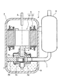
- FIG. 1 is a schematic vertical sectional view of a compressor according to a first embodiment of the present disclosure.
- FIG. 2 is a diagram of the motor according to the first embodiment of the present disclosure as viewed from an axial direction of the motor.
- FIG. 2 is a view of the rotor according to the first embodiment as viewed from an axial direction of the rotor.
- FIG. 3 is an enlarged view of a main part of the motor of FIG. 2.
- FIG. 2 is a schematic diagram illustrating an outer shape of a rotor core according to the first embodiment.
- FIG. 3 is a diagram illustrating a relationship between a circumferential position of the rotor and an electromagnetic force according to the first embodiment.
- FIG. 1 schematically shows a cross-sectional view when the compressor of the present embodiment is cut in a vertical plane.
- the compressor 1 includes a closed container 2, a compression mechanism 3 disposed in the closed container 2, and a motor 5 disposed in the closed container 2 and driving the compression mechanism 3 via a shaft 4. .
- This compressor 1 can be used for an air conditioner, for example.
- the compressor 1 is a so-called vertical high-pressure dome-type rotary compressor, in which a compression mechanism 3 is arranged below a closed container 2, and a motor 5 is arranged above the compression mechanism 3. I have.
- the compression mechanism 3 is driven via the shaft 4 by the rotor 10 of the motor 5.
- the shaft 4 is an example of a rotating shaft according to the present disclosure.
- the compression mechanism 3 sucks refrigerant gas from the accumulator 6 through the suction pipe 7.
- This refrigerant gas is obtained by controlling a condenser, an expansion mechanism, and an evaporator (not shown) that constitute an air conditioner as an example of a refrigeration system together with the compressor 1.
- the compressor 1 discharges the compressed high-temperature and high-pressure refrigerant gas from the compression mechanism 3 and fills the inside of the closed container 2.
- the refrigerant gas is discharged to the outside from a discharge pipe 8 provided above the motor 5 through a gap between the rotor 10 and the stator 20 of the motor 5 and the like. Further, an oil reservoir 9 in which lubricating oil is stored is formed below the high-pressure area in the sealed container 2.
- the compression mechanism 3 includes a cylinder 3a attached to the inner surface of the closed container 2, and upper and lower end plate members 3b and 3c attached to upper and lower open ends of the cylinder 3a, respectively. .
- a cylinder chamber 3d is formed by the cylinder 3a, the upper end plate member 3b, and the lower end plate member 3c.
- FIG. 2 is a view of the motor according to the present embodiment viewed from the axial direction of the motor.
- the motor 5 of the present embodiment is a so-called 6-pole, 9-slot inner rotor type.
- the motor 5 includes a rotor 10 and a stator 20 arranged so as to surround an outer peripheral surface of the rotor 10.
- An uneven air gap is provided between the stator 20 and the rotor 10 in the circumferential direction of the rotor 10. Further, the rotor 10 and the stator 20 are arranged such that the center of the rotor 10 and the center of the stator 20 match.
- the stator 20 includes a stator core 21 and a stator coil (not shown) wound around a later-described tooth portion 23 of the stator core 21.
- a stator coil (not shown) wound around a later-described tooth portion 23 of the stator core 21.
- the stator core 21 of the present embodiment has an annular yoke portion 22 and nine teeth portions 23 protruding radially inward of the stator core 21 from the inner peripheral surface of the yoke portion 22.
- the teeth 23 are arranged at regular intervals along the circumferential direction of the stator core 21. Specifically, the teeth 23 are arranged at intervals of 40 degrees along the circumferential direction of the stator core 21 around the axis of the stator core 21. In other words, the nine teeth portions 23 are arranged at positions that are symmetrical nine times with respect to the axis of the stator core 21.
- the teeth 23 extend from the inner peripheral surface of the yoke 22 toward the axis of the stator core 21.
- a slot 24 is formed between the two teeth 23 adjacent to each other in the circumferential direction of the stator core 21.
- the stator core 21 has nine slots 24 arranged at equal intervals along the circumferential direction of the stator core 21.
- the slots 24 are arranged at intervals of 40 degrees around the axis in the circumferential direction of the stator core 21. That is, the nine slots 24 are arranged at positions that are symmetrical nine times with respect to the axis of the stator core 21.
- FIG. 3 is a view of the rotor 10 according to the present embodiment as viewed from the axial direction of the rotor 10.
- the rotor 10 includes a columnar rotor core 11 and six permanent magnets 30 inserted into six magnet insertion holes 15 (described later) of the rotor core 11.
- the rotor core 11 of the present embodiment includes a shaft hole 12, six ventilation holes 13, six rivet holes 14, and six magnet insertion holes 15.
- the shaft hole 12, the ventilation hole 13, the rivet hole 14, and the magnet insertion hole 15 pass through the rotor core 11 in the axial direction of the rotor core 11.
- the shaft hole 12 is provided at the center of the rotor core 11.
- the shaft hole 12 is configured so that the shaft 4 (shown in FIG. 1) of the motor 5 can be inserted.
- the ventilation holes 13 are arranged at equal intervals along the circumferential direction of the rotor core 11. Specifically, the ventilation holes 13 are provided at intervals of 60 degrees around the axis O1 of the rotor core 11 along the circumferential direction of the rotor core 11. In other words, the six ventilation holes 13 are arranged at positions that are symmetrical six times with respect to the axis O1 of the rotor core 11.
- the rivet holes 14 are arranged at equal intervals along the circumferential direction of the rotor core 11. Specifically, the rivet holes 14 are provided at intervals of 60 degrees around the axis O1 of the rotor core 11 along the circumferential direction of the rotor core 11. In other words, the six rivet holes 14 are arranged at positions that are symmetrical six times with respect to the axis O1 of the rotor core 11.
- the rivet hole 14 is configured to allow a rivet (not shown) to be inserted.
- the magnet insertion hole 15 has a substantially rectangular shape that extends perpendicular to the radial direction of the rotor core 11 when viewed from the axial direction of the rotor core 11, and is configured to allow the permanent magnet 30 to be inserted.
- the magnet insertion holes 15 are provided radially outside the rotor core 11 with respect to the ventilation holes 13, and are arranged at equal intervals along the circumferential direction of the rotor core 11. Specifically, the magnet insertion holes 15 are arranged at intervals of 60 degrees around the axis O1 of the rotor core 11 along the circumferential direction of the rotor core 11. In other words, the six magnet insertion holes 15 are arranged at positions that are symmetrical six times with respect to the axis O1 of the rotor core 11.
- the magnet insertion hole 15 is provided so as to draw a hexagon when viewed from the axial direction of the rotor core 11.
- the magnet insertion hole 15 includes a magnetic flux short-circuit preventing portion 15a for preventing a magnetic flux short-circuit of the permanent magnet 30 at both ends in the extending direction.
- the magnetic flux short-circuit preventing portion 15a is a space in the magnet insertion hole 15 where the permanent magnet 30 is not arranged.
- the permanent magnet 30 is rectangular when viewed from the axial direction of the rotor core 11, and is inserted into the magnet insertion hole 15.
- the permanent magnets 30 are arranged at equal intervals along the circumferential direction of the rotor core 11. Specifically, the permanent magnets 30 are arranged at intervals of 60 degrees around the axis O1 of the rotor core 11 along the circumferential direction of the rotor core 11. In other words, the six permanent magnets 30 are arranged at positions that are six-fold symmetric with respect to the axis O1 of the rotor core 11.
- the permanent magnet 30 is provided so as to draw a hexagon when viewed from the axial direction of the rotor core 11 by being inserted into the magnet insertion hole 15.
- the rotor core 11 has a d-axis corresponding to a line connecting the longitudinal center of the permanent magnet 30 and the axis O1 of the rotor core 11.
- the d-axis is a line that bisects the permanent magnet 30 when viewed from the axial direction of the rotor core 11.
- the direction in which the d-axis extends is a direction in which the magnetic flux is unlikely to flow.
- the d-axis extends in a direction forming a mechanical angle of 30 deg with respect to a q-axis described later.
- the rotor core 11 has a q-axis corresponding to a line connecting a midpoint between two opposing ends of two magnet insertion holes 15 adjacent in the circumferential direction of the rotor core 11 and the axis O1 of the rotor core 11. .
- the direction in which the q axis extends is a direction in which the magnetic flux easily flows.
- the q-axis extends in a direction forming a mechanical angle of 30 deg with respect to the d-axis.
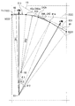
- FIG. 4 is an enlarged view of a main part of the motor 5 according to the present embodiment.
- the shaft hole 12, the ventilation hole 13, and the rivet hole 14 are omitted.
- the rotor core 11 of the present embodiment includes a first arc portion 40 provided to intersect with the d-axis, a linear portion 41 provided to be orthogonal to the q-axis, and a first arc portion. It has a curved portion 42 that connects the linear portion 40 to the linear portion 41.
- the straight portion 41 and the curved portion 42 are arranged radially inward of the virtual circle VC1 partially including the first arc portion 40.
- the first arc portion 40 has an arc shape with a radius of curvature CR1 about the axis O1 of the rotor core 11. Further, the first arc portion 40 intersects the d-axis at the center in the circumferential direction of the first arc portion 40. The first arc portion 40 is arranged outside the permanent magnet 30 in the radial direction of the rotor core 11.
- the air gap G between the rotor 10 and the stator 20 is constant and minimum in the first arc portion 40.
- the linear portion 41 is linear, and extends perpendicularly to the q-axis at the center of the direction in which the linear portion 41 extends.
- the straight portion 41 is disposed radially outside the rotor core 11 with respect to the magnetic flux short-circuit preventing portion 15a of the magnet insertion hole 15.
- the extending direction of the linear portion 41 is orthogonal to the radial direction of the rotor core 11.
- the straight portion 41 is disposed radially inward of the virtual circle VC1 partially including the first arc portion 40.
- the distance d between the axis O1 of the rotor core 11 and the center in the extending direction of the linear portion 41 is smaller than the radius of curvature CR1 of the first arc portion 40.
- the distance d between the axis O ⁇ b> 1 of the rotor core 11 and the center in the extending direction of the linear portion 41 is equal to the first arc portion 40. Is preferably 0.97 times or more of the curvature radius CR1.
- the outer shape of the rotor core 11 is a shape that is recessed inward in the radial direction of the rotor core 11 in the linear portion 41.
- the resistance generated between the rotor core 11 and the fluid containing the refrigerant, the mist-like lubricating oil, and the like corresponds to the fluid resistance.
- the air gap G between the rotor 10 and the stator 20 gradually increases from both ends in the extending direction of the straight portion 41 toward the center of the straight portion 41, and reaches a maximum at the center in the extending direction of the straight portion 41.
- the curved portion 42 of the present embodiment is formed of a second arc portion 43 having a radius of curvature CR2 (shown in FIG. 5) bulging outward in the radial direction of the rotor core 11 and having an arc shape.
- the radius of curvature CR2 of the second arc portion 43 is smaller than the radius of curvature CR1 of the first arc portion 40.
- the curved portion 42 is disposed radially inward of the virtual circle VC ⁇ b> 1 partially including the first arc portion 40.
- the air gap G between the rotor 10 and the stator 20 gradually increases in the second arc portion 43 of the curved portion 42 from the first arc portion 40 toward the straight portion 41.
- the air gap G between the rotor 10 and the stator 20 is minimum and constant in the first arc portion 40, gradually widens in the second arc portion 43 and the straight portion 41 of the curved portion 42, and gradually increases in the straight portion.
- the maximum is at the center of 41.
- the amount of change in the air gap G in the second arc portion 43 of the curved portion 42 is larger than the amount of change in the air gap G in the straight portion 41. In other words, the air gap G expands more gradually in the straight portion 41 than in the second arc portion 43 of the curved portion 42.
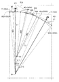
- FIG. 5 is a schematic diagram showing the outer shape of the rotor core 11 according to the present embodiment.
- the illustration of the shaft hole 12, the ventilation hole 13, the rivet hole 14, and the magnet insertion hole 15 of the rotor core 11 is omitted.
- the second arc portion 43 has an arc shape centered on the center point O2.
- the center point O2 is a line L1 connecting the end point 40a of the first arc portion 40 and the axis O1 of the rotor core 11, and a straight line L2 passing through the end point 41a of the straight portion 41 and extending in a direction orthogonal to the extending direction of the straight portion 41. Is the intersection with
- the second arc portion 43 smoothly connects the first arc portion 40 and the linear portion 41.
- the radius of curvature CR2 of the second arc portion 43 is smaller than the radius of curvature CR1 of the first arc portion 40.
- the angle range ⁇ 1 of the first circular arc portion 40 is smaller than the angle range ⁇ 2 of the linear portion 41.
- the angle range ⁇ 3 of the curved portion 42 is larger than the angle range ⁇ 2 of the linear portion 41. That is, the relationship of ⁇ 3> ⁇ 2> ⁇ 1 is established between the angle range ⁇ 1 of the first circular arc portion 40, the angle range ⁇ 2 of the linear portion 41, and the angle range ⁇ 3 of the curved portion.
- the first arc portion 40 and the second arc portion 43 of the present embodiment are directly connected. Specifically, the first arc portion 40 is connected to the second arc portion 43 at an end point 40 a of the first arc portion 40, and the second arc portion 43 is connected to the first arc portion 40 of the second arc portion 43. Is connected to the first arc portion 40 at the end point 43a on the side.
- first arc portion 40 and the second arc portion 43 are smoothly connected. Specifically, the tangent line T1 of the first arc portion 40 at the end point 40a of the first arc portion 40 connected to the second arc portion 43 is the end point 43a of the second arc portion 43 connected to the first arc portion 40. And the tangent line T2 of the second arc portion 43 in FIG.
- the tangent line T1 of the first arc portion 40 at the end point 40a connected to the second arc portion 43 of the first arc portion 40 is the first arc portion 40 of the virtual circle VC1 partially including the first arc portion 40. Is a tangent at an end point 40a on the second arc portion 43 side.
- the tangent line T2 of the second arc portion 43 at the end point 43a connected to the first arc portion 40 of the second arc portion 43 is the second arc portion 43 of the virtual circle VC2 including the second arc portion 43 as a part. Is a tangent line at an end point 43a on the first arc portion 40 side.
- the straight part 41 and the second arc part 43 of the present embodiment are directly connected. Specifically, the straight portion 41 is connected to the second arc portion 43 at an end point 41 a of the straight portion 41, and the second arc portion 43 is linearly connected to an end point 43 b on the straight portion 41 side of the second arc portion 43. It is connected to the unit 41.
- the straight part 41 and the second arc part 43 are smoothly connected. Specifically, the direction in which the tangent T3 of the second arc portion 43 extends at the end point 43b connected to the straight portion 41 of the second arc portion 43 coincides with the direction in which the straight portion 41 extends.
- the tangent T3 of the second arc portion 43 at the end point 43b connected to the linear portion 41 of the second arc portion 43 is the tangent T3 of the second arc portion 43 of the virtual circle VC2 partially including the second arc portion 43. It is a tangent line at the end point 43b on the side of the linear portion 41.
- the distance d (shown in FIG. 4) between the axis O1 of the rotor core 11 and the center in the extending direction of the linear portion 41 and the linear portion 41 as viewed from the axis O1 of the rotor core 11 Is determined and the radius of curvature CR1 of the first arc portion 40 is determined, the angle range ⁇ 1 of the first arc portion 40 as viewed from the axis O1 of the rotor core 11, the first arc portion 40 and the linear portion 41 are determined. May be uniquely determined with the curved portion 42 (the second circular arc portion 43) that smoothly connects.
- the distance d between the axis O1 of the rotor core 11 and the center in the extending direction of the linear portion 41, the radius of curvature CR1 of the first arc portion 40, and the first arc portion viewed from the axis O1 of the rotor core 11 Is determined, the angle range ⁇ 2 of the linear portion 41 as viewed from the axis O1 of the rotor core 11 and the curved portion 42 (the second portion) that smoothly connects the first arc portion 40 and the linear portion 41.
- the arc portion 43) may be uniquely determined in some cases.
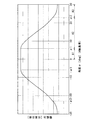
- FIG. 6 is a graph showing the relationship between the circumferential position of the rotor 10 of the present embodiment and the electromagnetic force generated between the rotor 10 and the stator 20.
- the vertical axis of the graph in FIG. 6 represents the electromagnetic force [arbitrary scale] generated between the rotor 10 and the stator 20.
- the electromagnetic force generated between the rotor 10 and the stator 20 is proportional to the square of the reciprocal of the air gap between the rotor 10 and the stator 20.
- the electromagnetic force generated between the rotor 10 and the stator 20 in the region A1 is constant because the first arc portion 40 has an arc shape centered on the axis O1 of the rotor core 11, so that the first arc portion 40 In this case, the air gap G (shown in FIG. 4) between the rotor 10 and the stator 20 is constant.
- the electromagnetic force generated between the rotor 10 and the stator 20 is a mechanical force based on the d-axis of the rotor 10. It decreases as the angle ⁇ increases.
- the area A2 is In the outer shape of the rotor core 11, it corresponds to the second arc portion 43 of the curved portion.
- the electromagnetic force generated between the rotor 10 and the stator 20 smoothly changes between the region A1 and the region A2. This is because the second arc portion 43 is smoothly connected to the first arc portion 40.
- the region A3 corresponds to the linear portion 41 in the outer shape of the rotor core 11.
- the change in the electromagnetic force generated between the rotor 10 and the stator 20 in the region A3 is gentler than the change in the electromagnetic force generated between the rotor 10 and the stator 20 in the region A2. This is because the air gap G (shown in FIG. 4) between the rotor 10 and the stator 20 is more gradually expanded in the straight portion 41 than in the second arc portion 43 of the curved portion 42.
- the electromagnetic force generated between the rotor 10 and the stator 20 changes smoothly between the region A2 and the region A3. This is because the second arc portion 43 is smoothly connected to the linear portion 41.
- the curved portion 42 including the second circular arc portion 43 forms a straight line with the first circular arc portion 40.
- the portion 41 is smoothly connected. Therefore, a sudden change in the air gap G between the rotor 10 and the stator 20 due to the rotation of the rotor 10 is suppressed, so that a sudden change in the electromagnetic force generated between the rotor 10 and the stator 20 is suppressed. Because it is suppressed, higher-order electromagnetic forces are reduced. As a result, vibration caused by the higher-order electromagnetic force can be effectively suppressed.
- the fluid resistance (stirring loss) during rotation of the rotor 10 is reduced while effectively suppressing vibration. it can.
- the fluid resistance (stirring loss) during rotation of the rotor 10 can be reduced while effectively suppressing vibration.
- the electromagnetic force generated between the rotor 10 and the stator 20 in the region near the d-axis of the rotor core 11 is maximum and constant.
- the characteristics (generated torque) can be fully exhibited.
- the electromagnetic force generated between the rotor 10 and the stator 20 can be reduced in a region near the q-axis of the rotor core 11 (region A3 in FIG. 6), the electromagnetic force generated between the motor 5 and the rotor 10 can be reduced. Vibration caused by force can be suppressed.
- the rotor 10 of the motor 5 of the present embodiment it is possible to suppress the vibration caused by the electromagnetic force generated between the motor 5 and the stator 20 while suppressing the decrease in the torque generated by the motor 5 and reduce the noise. Can be suppressed.
- the rotor core 111 according to the second embodiment is the same as the first embodiment except for the configuration of the curved portion 142.
- the same components as those in the first embodiment are denoted by the same reference numerals, and description thereof will be omitted.
- FIG. 7 is a diagram schematically showing the outer shape of the rotor core 111 according to the second embodiment.
- the curved portion 142 of the present embodiment is disposed radially inside a virtual circle VC1 partially including the first arc portion 40.
- the curved portion 142 of the present embodiment includes a second circular arc portion 143 that has a circular arc shape bulging outward in the radial direction.
- the radius of curvature of the second arc portion 143 is smaller than the radius of curvature CR1 of the first arc portion 40.
- the first arc portion 40 and the second arc portion 143 of the present embodiment are directly connected. Specifically, the first arc portion 40 is connected to the second arc portion 143 at an end point 40a of the first arc portion 40, and the second arc portion 143 is connected to the first arc portion 40 of the second arc portion 143. It is connected to the first arc portion 40 at the end point 143a on the side.
- the first arc portion 40 and the second arc portion 143 are substantially smoothly connected. Specifically, the inclination of the tangent line T1 of the first arc portion 40 at the end point 40a of the first arc portion 40 connected to the second arc portion 143 is connected to the first arc portion 40 of the second arc portion 143. The inclination substantially coincides with the inclination of the tangent T21 of the second arc portion 143 at the end point 143a.
- the tangent T21 of the second arc 143 at the end point 143a connected to the first arc 40 of the second arc 143 is the second arc 143 of the virtual circle VC21 partially including the second arc 143. Is a tangent at the end point 143a on the first arc portion 40 side.
- the fluid resistance (stirring loss) during rotation of the rotor can be reduced while suppressing vibration. Can be reduced.
- the rotor core 211 according to the third embodiment is the same as the first embodiment except for the configuration of the curved portion 242.
- the same components as those in the first embodiment are denoted by the same reference numerals, and description thereof will be omitted.
- FIG. 8 is a diagram schematically illustrating the outer shape of the rotor core 211 according to the third embodiment.
- the bending portion 242 of the present embodiment includes a second arc portion 243 arranged on the first arc portion 40 side and a straight portion 244 arranged on the straight portion 41 side.
- the second arc portion 243 of the present embodiment has an arc shape with a radius of curvature CR2 centered on the center point O2.
- the first arc portion 40 and the second arc portion 243 of the present embodiment are directly connected. Specifically, the first arc portion 40 is connected to the second arc portion 243 at an end point 40 a of the first arc portion 40, and the second arc portion 243 is connected to the first arc portion 40 of the second arc portion 243. It is connected to the first arc portion 40 at an end point 243a on the side.
- the first arc portion 40 and the second arc portion 243 are smoothly connected. Specifically, the tangent T1 of the first arc portion 40 at the end point 40a of the first arc portion 40 connected to the second arc portion 243 is the end point 243a of the second arc portion 243 connected to the first arc portion 40. And the tangent line T22 of the second arc portion 243 in FIG.
- the tangent line T22 of the second arc portion 243 at the end point 243a connected to the first arc portion 40 of the second arc portion 243 is the second arc portion 243 of the virtual circle VC22 partially including the second arc portion 243. Is a tangent line at an end point 243a on the first arc portion 40 side.
- the straight part 41 and the second arc part 243 of the present embodiment are connected via the straight part 244 of the curved part 242.
- the straight portion 41 is connected to the straight portion 244 of the curved portion 242 at an end point 41a of the straight portion 41
- the second arc portion 243 is connected to an end point 243b of the second arc portion 243 on the straight portion 41 side. Is connected to the straight portion 244 of the curved portion 242.
- the rotor core 311 according to the fourth embodiment is the same as the first embodiment except for the configuration of the curved portion 342.
- the same components as those in the first embodiment are denoted by the same reference numerals, and description thereof will be omitted.
- FIG. 9 is a diagram schematically illustrating the outer shape of the rotor core 311 according to the third embodiment.
- the curved portion 342 of the present embodiment includes a second arc portion 343 arranged on the straight portion 41 side and a straight portion 344 arranged on the first arc portion 40 side.
- the second arc portion 343 of the present embodiment has an arc shape with a radius of curvature CR2 centered on the center point O2.
- the straight part 41 and the second arc part 343 of the present embodiment are directly connected. Specifically, the straight portion 41 is connected to the second arc portion 343 at an end point 41a of the straight portion 41, and the second arc portion 343 is straightened at an end point 343b of the second arc portion 343 on the straight portion 41 side. It is connected to the unit 41.
- the straight part 41 and the second arc part 343 are smoothly connected. Specifically, the direction in which the tangent T33 of the second arc portion 343 extends at the end point 343b connected to the straight portion 41 of the second arc portion 343 matches the direction in which the straight portion 41 extends.
- the tangent line T33 of the second arc portion 343 at the end point 343b connected to the straight portion 41 of the second arc portion 343 is the same as the tangent T33 of the second arc portion 343 of the virtual circle VC23 partially including the second arc portion 343. It is a tangent line at the end point 343b on the straight line portion 41 side.
- the first arc portion 40 and the second arc portion 343 of the present embodiment are connected via a straight portion 344 of the curved portion 342.
- the first arc portion 40 is connected to the straight portion 344 of the curved portion 342 at an end point 40 a of the first arc portion 40
- the second arc portion 343 is connected to the first arc of the second arc portion 343. It is connected to the straight portion 344 of the curved portion 342 at an end point 343a on the side of the portion.
- the rotor core 411 according to the fifth embodiment is the same as the first embodiment except for the configuration of the curved portion 442.
- the same components as those in the first embodiment are denoted by the same reference numerals, and description thereof will be omitted.
- FIG. 10 is a diagram schematically showing the outer shape of the rotor core 411 according to the fifth embodiment.
- the curved portion 442 of the present embodiment includes a second arc portion 443 arranged on the first arc portion 40 side, a third arc portion 444 arranged on the straight line portion 41 side, and a second arc portion.
- a straight portion 445 connecting the portion 443 and the third arc portion 444 is provided.
- the second arc portion 443 of the present embodiment has an arc shape with a radius of curvature CR2 centered on the center point O2.
- the third arc portion 444 of the present embodiment has an arc shape with a radius of curvature CR2 centered on the center point O2.
- the first arc portion 40 and the second arc portion 443 of the present embodiment are directly connected. Specifically, the first arc portion 40 is connected to the second arc portion 443 at an end point 40a of the first arc portion 40, and the second arc portion 443 is connected to the first arc portion 40 of the second arc portion 443. It is connected to the first arc portion 40 at the end point 443a on the side.
- the first arc portion 40 and the second arc portion 443 are smoothly connected. Specifically, the tangent line T1 of the first arc portion 40 at the end point 40a of the first arc portion 40 connected to the second arc portion 443 is the end point 443a of the second arc portion 443 connected to the first arc portion 40. And the tangent line T24 of the second arc portion 443 in FIG.
- the tangent line T24 of the second arc portion 443 at the end point 443a connected to the first arc portion 40 of the second arc portion 443 is the second arc portion 443 of the virtual circle VC24 partially including the second arc portion 443. Is a tangent at the end point 443a on the first arc portion 40 side.
- the straight part 41 and the third circular arc part 444 of the present embodiment are directly connected. Specifically, the straight portion 41 is connected to the third arc portion 444 at an end point 41a of the straight portion 41, and the third arc portion 444 is straight at an end point 444b on the straight portion 41 side of the third arc portion 444. It is connected to the unit 41.
- the straight portion 41 and the third arc portion 444 are smoothly connected. Specifically, the direction in which the tangent T34 of the third arc portion 444 extends at the end point 444b connected to the straight portion 41 of the third arc portion 444 coincides with the direction in which the straight portion 41 extends.
- the tangent T34 of the third arc portion 444 at the end point 444b connected to the straight portion 41 of the third arc portion 444 is the tangent T34 of the third arc portion 444 of the virtual circle VC34 partially including the third arc portion 444. This is a tangent line at an end point 444b on the side of the linear portion 41.
- the number of poles of the rotor according to the present disclosure is not limited to six as in the first to fifth embodiments, and may be another number (for example, four).
- the shape of the rotor may be determined based on the pole number ratio (6 / X, where X is the number of other poles).
Landscapes
- Engineering & Computer Science (AREA)
- Power Engineering (AREA)
- Physics & Mathematics (AREA)
- Mechanical Engineering (AREA)
- Thermal Sciences (AREA)
- General Engineering & Computer Science (AREA)
- Iron Core Of Rotating Electric Machines (AREA)
- Connection Of Motors, Electrical Generators, Mechanical Devices, And The Like (AREA)
- Permanent Magnet Type Synchronous Machine (AREA)
- Permanent Field Magnets Of Synchronous Machinery (AREA)
Abstract
Description
図1は、本実施形態の圧縮機を鉛直面で切ったときの断面図を模式的に示す。 [First Embodiment]
FIG. 1 schematically shows a cross-sectional view when the compressor of the present embodiment is cut in a vertical plane.
以下、本実施形態に係るロータコア11の1極分の外形形状を説明する。図4は、本実施形態に係るモータ5の要部拡大図である。図4では、軸孔12、通風孔13、リベット孔14は省略している。 (Outer shape of rotor core)
Hereinafter, the outer shape of one pole of the
第2実施形態に係るロータコア111は、湾曲部142の構成を除いて上記第1実施形態と同様である。第2実施形態において、上記第1実施形態と同一の構成には、同一の参照番号を付して、その説明を省略する。 [Second embodiment]
The
第3実施形態に係るロータコア211は、湾曲部242の構成を除いて上記第1実施形態と同様である。第3実施形態において、上記第1実施形態と同一の構成には、同一の参照番号を付して、その説明を省略する。 [Third embodiment]
The
第4実施形態に係るロータコア311は、湾曲部342の構成を除いて上記第1実施形態と同様である。第4実施形態において、上記第1実施形態と同一の構成には、同一の参照番号を付して、その説明を省略する。 [Fourth embodiment]
The
第5実施形態に係るロータコア411は、湾曲部442の構成を除いて上記第1実施形態と同様である。第5実施形態において、上記第1実施形態と同一の構成には、同一の参照番号を付して、その説明を省略する。 [Fifth Embodiment]
The
2…密閉容器
3…圧縮機構部
3a…シリンダ
3b,3c…端板部材
3d…シリンダ室
4…シャフト
5…モータ
6…アキュムレータ
7…吸入管
8…吐出管
9…油溜まり部
10…ロータ
11…ロータコア
12…軸孔
13…通風孔
14…リベット孔
15,15A,15B…磁石挿通孔
15a…磁束短絡防止部
20…ステータ
21…ステータコア
22…ヨーク部
23…ティース部
24…スロット
30…永久磁石
40…第1円弧部
40a…端点
41…直線部
41a…端点
42…湾曲部
43…第2円弧部
43a…端点
43b…端点
111…ロータコア
142…湾曲部
143…第2円弧部
143a…端点
211…ロータコア
242…湾曲部
243…第2円弧部
243a…端点
243b…端点
244…直線部分
311…ロータコア
342…湾曲部
343…第2円弧部
343a…端点
343b…端点
344…直線部分
411…ロータコア
442…湾曲部
443…第2円弧部
443a…端点
444…第3円弧部
444b…端点
445…直線部分 DESCRIPTION OF SYMBOLS 1 ...
Claims (8)
- d軸と交差するように設けられた第1円弧部(40)と、
q軸と交差するように設けられた直線部(41)と、
上記第1円弧部(40)と上記直線部(41)との間を接続する湾曲部(42,142,242,342,442)と
を有する外形形状からなるロータコア(11)を備え、
上記第1円弧部(40)は、上記ロータコア(11)の軸心(O1)を中心とする円弧状であり、
上記湾曲部(42,142,242,342,442)は、上記ロータコア(11)の半径方向外側に膨出した円弧状の第2円弧部(43,143,243,343,443)を含み、
上記第2円弧部(43,143,243,343,443)の曲率半径(CR2)は、上記第1円弧部(40)の曲率半径(CR1)よりも小さいことを特徴とする、ロータ(10)。 a first arc portion (40) provided to intersect the d-axis;
a straight line portion (41) provided so as to intersect with the q axis;
A rotor core (11) having an outer shape having a curved portion (42, 142, 242, 342, 442) connecting between the first arc portion (40) and the linear portion (41);
The first arc portion (40) has an arc shape centered on the axis (O1) of the rotor core (11),
The curved portions (42, 142, 242, 342, 442) include arc-shaped second arc portions (43, 143, 243, 343, 443) bulging radially outward of the rotor core (11),
The radius of curvature (CR2) of the second arc portion (43, 143, 243, 343, 443) is smaller than the radius of curvature (CR1) of the first arc portion (40). ). - 請求項1に記載のロータ(10)であって、
上記ロータコア(11)の上記軸心(O1)から見て、上記直線部(41)の周方向の角度範囲(θ2)は、上記第1円弧部(40)の周方向の角度範囲(θ1)よりも大きいことを特徴とする、ロータ(10)。 The rotor (10) according to claim 1, wherein:
As viewed from the axis (O1) of the rotor core (11), the circumferential angular range (θ2) of the linear portion (41) is the circumferential angular range (θ1) of the first arc portion (40). A rotor (10) characterized by being larger than - 請求項1又は2に記載のロータ(10)であって、
上記ロータコア(11)の上記軸心(O1)から見て、上記湾曲部(42,142,242,342,442)の周方向の角度範囲(θ3)は、上記直線部(41)の周方向の角度範囲(θ2)よりも大きいことを特徴とする、ロータ(10)。 The rotor (10) according to claim 1 or 2, wherein:
When viewed from the axis (O1) of the rotor core (11), the angular range (θ3) in the circumferential direction of the curved portion (42, 142, 242, 342, 442) is in the circumferential direction of the linear portion (41). The rotor (10), which is larger than the angle range (θ2). - 請求項1から3のいずれか1項に記載のロータ(10)であって、
上記第1円弧部(40)と上記第2円弧部(143)とは、直接接続されており、
上記第2円弧部(143)の上記第1円弧部(40)に接続された端点(143a)における上記第2円弧部(143)の接線(T21)の傾きは、上記第1円弧部(40)の上記第2円弧部(143)に接続された端点(40a)における上記第1円弧部(40)の接線(T1)の傾きと実質的に一致することを特徴とする、ロータ(10)。 A rotor (10) according to any one of the preceding claims, wherein:
The first arc portion (40) and the second arc portion (143) are directly connected,
The inclination of the tangent (T21) of the second arc portion (143) at the end point (143a) of the second arc portion (143) connected to the first arc portion (40) is equal to the inclination of the first arc portion (40). ) Substantially coincides with the inclination of the tangent (T1) of the first arc portion (40) at the end point (40a) connected to the second arc portion (143). . - 請求項1から3のいずれか1項に記載のロータ(10)であって、
上記第1円弧部(40)と上記第2円弧部(43,243,443)とは、直接接続されており、
上記第2円弧部(43,243,443)の上記第1円弧部(40)に接続された端点(43a,243a,443a)における上記第2円弧部(43,143,243,443)の接線(T2,T22,T24)は、上記第1円弧部(40)の上記第2円弧部(43,243,443)に接続された端点(40a)における上記第1円弧部(40)の接線(T1)に一致することを特徴とする、ロータ(10)。 A rotor (10) according to any one of the preceding claims, wherein:
The first arc portion (40) and the second arc portion (43, 243, 443) are directly connected,
A tangent to the second arc portion (43, 143, 243, 443) at an end point (43a, 243a, 443a) of the second arc portion (43, 243, 443) connected to the first arc portion (40). (T2, T22, T24) is a tangent to the first arc portion (40) at an end point (40a) of the first arc portion (40) connected to the second arc portion (43, 243, 443). A rotor (10), characterized in that it corresponds to T1). - 請求項1から5のいずれか1項に記載のロータ(10)であって、
上記第2円弧部(43,343)と上記直線部(41)とは、直接接続されており、
上記第2円弧部(43,343)の上記直線部(41)に接続された端点(43b,343b)における上記第2円弧部(43,343)の接線(T3,T33)は、上記直線部(41)が延びている方向に延びることを特徴とする、ロータ(10)。 A rotor (10) according to any of the preceding claims, wherein:
The second arc portion (43, 343) and the straight portion (41) are directly connected,
The tangents (T3, T33) of the second arc portion (43, 343) at the end points (43b, 343b) connected to the linear portion (41) of the second arc portion (43, 343) are: A rotor (10) extending in the direction in which (41) extends. - 請求項1から6のいずれか1項に記載のロータ(10)と、
上記ロータ(10)の外周面を囲むように配置されたステータ(20)と
を備えたことを特徴とするモータ(5)。 A rotor (10) according to any one of the preceding claims,
A stator (20) arranged to surround the outer peripheral surface of the rotor (10). - 密閉容器(2)と、
上記密閉容器(2)内に配置された圧縮機構部(3)と、
上記密閉容器(2)内に配置されて、上記圧縮機構部(3)を回転軸(4)を介して駆動する、請求項7に記載されたモータ(5)と
を備えたことを特徴とする圧縮機(1)。 A closed container (2);
A compression mechanism (3) disposed in the closed container (2);
The motor (5) according to claim 7, wherein the motor (5) is disposed in the closed container (2) and drives the compression mechanism (3) via a rotating shaft (4). Compressor (1).
Priority Applications (4)
| Application Number | Priority Date | Filing Date | Title |
|---|---|---|---|
| EP19865327.1A EP3832851A4 (en) | 2018-09-28 | 2019-08-20 | Rotor, motor, and compressor |
| US17/277,280 US11936244B2 (en) | 2018-09-28 | 2019-08-20 | Rotor, motor, and compressor |
| AU2019347290A AU2019347290B2 (en) | 2018-09-28 | 2019-08-20 | Rotor, motor, and compressor |
| CN201980054645.4A CN112585843B (en) | 2018-09-28 | 2019-08-20 | Rotor, motor and compressor |
Applications Claiming Priority (2)
| Application Number | Priority Date | Filing Date | Title |
|---|---|---|---|
| JP2018184111A JP6811222B2 (en) | 2018-09-28 | 2018-09-28 | Rotor, motor, and compressor |
| JP2018-184111 | 2018-09-28 |
Publications (1)
| Publication Number | Publication Date |
|---|---|
| WO2020066368A1 true WO2020066368A1 (en) | 2020-04-02 |
Family
ID=69952002
Family Applications (1)
| Application Number | Title | Priority Date | Filing Date |
|---|---|---|---|
| PCT/JP2019/032420 WO2020066368A1 (en) | 2018-09-28 | 2019-08-20 | Rotor, motor, and compressor |
Country Status (6)
| Country | Link |
|---|---|
| US (1) | US11936244B2 (en) |
| EP (1) | EP3832851A4 (en) |
| JP (1) | JP6811222B2 (en) |
| CN (1) | CN112585843B (en) |
| AU (1) | AU2019347290B2 (en) |
| WO (1) | WO2020066368A1 (en) |
Cited By (2)
| Publication number | Priority date | Publication date | Assignee | Title |
|---|---|---|---|---|
| CN111725923A (en) * | 2020-07-27 | 2020-09-29 | 威灵(芜湖)电机制造有限公司 | Motor and household appliance |
| WO2022214752A1 (en) * | 2021-04-08 | 2022-10-13 | Seb S.A. | Rotor for brushless synchronous motor with inserted permanent magnets |
Families Citing this family (1)
| Publication number | Priority date | Publication date | Assignee | Title |
|---|---|---|---|---|
| CN112968580A (en) * | 2021-02-03 | 2021-06-15 | 大连理工大学 | Rotor structure of built-in permanent magnet synchronous motor and design method |
Citations (5)
| Publication number | Priority date | Publication date | Assignee | Title |
|---|---|---|---|---|
| JP2002010541A (en) | 2000-06-16 | 2002-01-11 | Fanuc Ltd | Rotor of synchronous electric motor |
| JP2007295708A (en) * | 2006-04-24 | 2007-11-08 | Nidec Sankyo Corp | Permanent magnet embedded motor |
| WO2008139675A1 (en) * | 2007-05-07 | 2008-11-20 | Panasonic Corporation | Permanent magnet buried type electric motor |
| WO2013011546A1 (en) * | 2011-07-15 | 2013-01-24 | 三菱電機株式会社 | Permanent magnet motor and compressor, ventilator, and frozen air condition device using same |
| JP2014054155A (en) * | 2012-09-10 | 2014-03-20 | Nsk Ltd | Electric motor and electric power steering device |
Family Cites Families (4)
| Publication number | Priority date | Publication date | Assignee | Title |
|---|---|---|---|---|
| CN1715676A (en) | 2004-06-28 | 2006-01-04 | 乐金电子(天津)电器有限公司 | Refrigerant path device for closed rotary compressor |
| JP4135018B2 (en) * | 2006-04-24 | 2008-08-20 | 株式会社富士通ゼネラル | Magnet-embedded rotor, electric motor using the rotor, and compressor using the electric motor |
| CN206353733U (en) | 2016-10-28 | 2017-07-25 | 珠海格力节能环保制冷技术研究中心有限公司 | A kind of motor, rotor and rotor punching |
| CN207368762U (en) | 2017-11-09 | 2018-05-15 | 广东威灵电机制造有限公司 | Motor |
-
2018
- 2018-09-28 JP JP2018184111A patent/JP6811222B2/en active Active
-
2019
- 2019-08-20 US US17/277,280 patent/US11936244B2/en active Active
- 2019-08-20 CN CN201980054645.4A patent/CN112585843B/en active Active
- 2019-08-20 EP EP19865327.1A patent/EP3832851A4/en active Pending
- 2019-08-20 AU AU2019347290A patent/AU2019347290B2/en active Active
- 2019-08-20 WO PCT/JP2019/032420 patent/WO2020066368A1/en active Application Filing
Patent Citations (5)
| Publication number | Priority date | Publication date | Assignee | Title |
|---|---|---|---|---|
| JP2002010541A (en) | 2000-06-16 | 2002-01-11 | Fanuc Ltd | Rotor of synchronous electric motor |
| JP2007295708A (en) * | 2006-04-24 | 2007-11-08 | Nidec Sankyo Corp | Permanent magnet embedded motor |
| WO2008139675A1 (en) * | 2007-05-07 | 2008-11-20 | Panasonic Corporation | Permanent magnet buried type electric motor |
| WO2013011546A1 (en) * | 2011-07-15 | 2013-01-24 | 三菱電機株式会社 | Permanent magnet motor and compressor, ventilator, and frozen air condition device using same |
| JP2014054155A (en) * | 2012-09-10 | 2014-03-20 | Nsk Ltd | Electric motor and electric power steering device |
Cited By (3)
| Publication number | Priority date | Publication date | Assignee | Title |
|---|---|---|---|---|
| CN111725923A (en) * | 2020-07-27 | 2020-09-29 | 威灵(芜湖)电机制造有限公司 | Motor and household appliance |
| WO2022214752A1 (en) * | 2021-04-08 | 2022-10-13 | Seb S.A. | Rotor for brushless synchronous motor with inserted permanent magnets |
| FR3121799A1 (en) * | 2021-04-08 | 2022-10-14 | Seb S.A. | ROTOR FOR BRUSHLESS SYNCHRONOUS MOTOR WITH INSERTED PERMANENT MAGNETS |
Also Published As
| Publication number | Publication date |
|---|---|
| CN112585843B (en) | 2024-04-12 |
| EP3832851A1 (en) | 2021-06-09 |
| US20210296951A1 (en) | 2021-09-23 |
| AU2019347290B2 (en) | 2022-03-03 |
| JP2020054189A (en) | 2020-04-02 |
| JP6811222B2 (en) | 2021-01-13 |
| EP3832851A4 (en) | 2021-09-22 |
| US11936244B2 (en) | 2024-03-19 |
| AU2019347290A1 (en) | 2021-04-29 |
| CN112585843A (en) | 2021-03-30 |
Similar Documents
| Publication | Publication Date | Title |
|---|---|---|
| WO2020066368A1 (en) | Rotor, motor, and compressor | |
| WO2017077590A1 (en) | Stator, motor, compressor and refrigerating air-conditioner | |
| JP6479267B2 (en) | Stator, electric motor, compressor, and refrigeration air conditioner | |
| WO2010016583A1 (en) | Stator, motor, and compressor | |
| CN111033947B (en) | Rotor, motor, compressor, and air conditioner | |
| JP6789390B2 (en) | Reluctance motors, compressors and air conditioners | |
| JPWO2020003390A1 (en) | Electric motors, compressors, blowers, and refrigeration and air conditioners | |
| JP2023168510A (en) | Motor, compressor, air blower, and refrigerating air conditioner | |
| JP7034328B2 (en) | Rotors, motors, compressors, and refrigeration and air conditioning equipment | |
| JP2020162414A (en) | Rotor, motor, and compressor | |
| JPWO2020194504A1 (en) | Rotors, motors, compressors, and air conditioners | |
| JP6914424B2 (en) | Motors, compressors, blowers, and refrigerating air conditioners | |
| WO2020026431A1 (en) | Stator, motor, compressor, and refrigeration and air conditioning device | |
| WO2020053927A1 (en) | Rotor, electrical motor, compressor, and refrigerating air conditioning device | |
| CN113555980B (en) | Motor and compressor comprising same | |
| WO2016151907A1 (en) | Sealed rotary compressor and refrigeration cycle device | |
| WO2022130935A1 (en) | Blower device | |
| WO2020059056A1 (en) | Stator, motor, compressor and air conditioning device | |
| CN115224823A (en) | Stator core unit, stator core, motor and compressor |
Legal Events
| Date | Code | Title | Description |
|---|---|---|---|
| 121 | Ep: the epo has been informed by wipo that ep was designated in this application |
Ref document number: 19865327 Country of ref document: EP Kind code of ref document: A1 |
|
| ENP | Entry into the national phase |
Ref document number: 2019865327 Country of ref document: EP Effective date: 20210304 |
|
| WWE | Wipo information: entry into national phase |
Ref document number: 2101001668 Country of ref document: TH |
|
| NENP | Non-entry into the national phase |
Ref country code: DE |
|
| ENP | Entry into the national phase |
Ref document number: 2019347290 Country of ref document: AU Date of ref document: 20190820 Kind code of ref document: A |