WO2020065897A1 - User equipment - Google Patents
User equipment Download PDFInfo
- Publication number
- WO2020065897A1 WO2020065897A1 PCT/JP2018/036152 JP2018036152W WO2020065897A1 WO 2020065897 A1 WO2020065897 A1 WO 2020065897A1 JP 2018036152 W JP2018036152 W JP 2018036152W WO 2020065897 A1 WO2020065897 A1 WO 2020065897A1
- Authority
- WO
- WIPO (PCT)
- Prior art keywords
- start timing
- timing
- cell
- mgta
- lte
- Prior art date
Links
Images


Classifications
-
- H—ELECTRICITY
- H04—ELECTRIC COMMUNICATION TECHNIQUE
- H04W—WIRELESS COMMUNICATION NETWORKS
- H04W36/00—Hand-off or reselection arrangements
- H04W36/0005—Control or signalling for completing the hand-off
- H04W36/0083—Determination of parameters used for hand-off, e.g. generation or modification of neighbour cell lists
- H04W36/0085—Hand-off measurements
- H04W36/0088—Scheduling hand-off measurements
-
- H—ELECTRICITY
- H04—ELECTRIC COMMUNICATION TECHNIQUE
- H04W—WIRELESS COMMUNICATION NETWORKS
- H04W24/00—Supervisory, monitoring or testing arrangements
- H04W24/10—Scheduling measurement reports ; Arrangements for measurement reports
-
- H—ELECTRICITY
- H04—ELECTRIC COMMUNICATION TECHNIQUE
- H04W—WIRELESS COMMUNICATION NETWORKS
- H04W72/00—Local resource management
- H04W72/04—Wireless resource allocation
- H04W72/044—Wireless resource allocation based on the type of the allocated resource
- H04W72/0446—Resources in time domain, e.g. slots or frames
-
- H—ELECTRICITY
- H04—ELECTRIC COMMUNICATION TECHNIQUE
- H04W—WIRELESS COMMUNICATION NETWORKS
- H04W88/00—Devices specially adapted for wireless communication networks, e.g. terminals, base stations or access point devices
- H04W88/02—Terminal devices
- H04W88/06—Terminal devices adapted for operation in multiple networks or having at least two operational modes, e.g. multi-mode terminals
Definitions
- the present invention relates to a user device.
- LTE Long Term Evolution
- LTE-Advanced LTE-Advanced
- NR 5G New Radio
- NG Next Generation
- a user apparatus User Equipment, UE
- RF radio frequency
- RF retuning any data and control signals are transmitted and received for RF retuning.
- the measurement gap (MG) can be set as a period not to be performed.
- SSB SS / PBCH block
- SMTC RRM Measurement Timing Configuration
- the MG starts from the middle point (0.5 ms) of the LTE subframe (1 ms), but the NR subcarrier interval (for example, 15 kHz)
- the UE cannot obtain a reference timing that can be referred to in order to determine the start timing of the advanced MG.
- an object of the present invention is to provide a user apparatus that can maintain the start timing accuracy of a measurement gap (MG) even when the start timing of the MG differs.
- One embodiment of the present invention is a user apparatus (UE200), which includes a control unit (control unit 230) that controls a start timing of a measurement gap, wherein the control unit uses a reference timing used in a target cell. The start timing according to the type is applied.
- UE200 user apparatus
- control unit 230 controls a start timing of a measurement gap
- the control unit uses a reference timing used in a target cell.
- the start timing according to the type is applied.
- FIG. 1 is an overall schematic configuration diagram of the wireless communication system 10.
- FIG. 2 is a functional block configuration diagram of the UE 200.
- FIG. 3 is a schematic diagram of the operation of the MGTA.
- FIG. 4 is a diagram showing an example of the relationship between the MG start timing when MGTA is applied and the reference timing used in the target cell.
- FIG. 5 is a diagram illustrating an example of the MG start timing based on the operation example 1 and the operation example 2.
- FIG. 6 is a diagram illustrating a configuration example of an OFDM symbol.
- FIG. 7 is a diagram illustrating an example of a hardware configuration of the UE 200.
- FIG. 1 is an overall schematic configuration diagram of a wireless communication system 10 according to the present embodiment.
- the radio communication system 10 is a radio communication system according to Long Term Evolution (LTE) and 5G New Radio (NR), and includes a radio base station 100 (hereinafter, eNB100), a radio base station 110 (hereinafter, gNB110), and a user device. 200 (hereinafter, UE200).
- LTE Long Term Evolution
- NR 5G New Radio
- eNB100 radio base station 100
- gNB110 radio base station 110
- UE200 user device.
- the specific configuration of the wireless communication system 10 including the number of gNBs and UEs is not limited to the example shown in FIG.
- ENB 100 is a radio base station according to LTE, and forms one or a plurality of cells.
- the gNB 110 is a wireless base station according to 5G and forms one or a plurality of cells.
- the cell can constitute a Master Cell Group (MCG) and a Secondary Cell Group (SCG).
- the eNB 100 and the UE 200 execute wireless communication according to LTE using one or a plurality of carriers.
- the gNB 110 and the UE 200 execute wireless communication according to 5G using one or a plurality of carriers.
- eNB100, gNB110 and UE200 control a radio signal transmitted from a plurality of antenna elements to generate a more highly directive beam Massive MIMO, a carrier aggregation (CA) using a plurality of component carriers (CC), And dual connectivity (DC) for simultaneously transmitting component carriers between a plurality of NG-RAN nodes and the UE.
- Massive MIMO Massive MIMO
- CA carrier aggregation
- CC component carriers
- DC dual connectivity
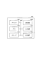
- FIG. 2 is a functional block configuration diagram of the UE 200. As shown in FIG. 2, the UE 200 includes a transmission unit 210, a reception unit 220, and a control unit 230.
- Transmission section 210 transmits an uplink signal (UL signal) according to NR.
- UL signal uplink signal
- the receiving unit 220 receives a downlink signal (DL signal) according to the NR.
- the receiving unit 220 receives a reference signal (RS). More specifically, the receiving unit 220 receives Radio Link Monitoring R (RLM-RS) and the like.
- RS Reference Signal
- RLM-RS Radio Link Monitoring R
- the control unit 230 performs control on the UL signal transmitted by the transmission unit 210 and the DL signal received by the reception unit 220.
- control unit 230 performs measurement on a carrier (beam) transmitted from the eNB 100 or the gNB 110. Specifically, control section 230 performs measurement of cell quality using the measurement gap.
- Measurement gap is understood as the period during which no data and control signals are transmitted or received for the purpose of measuring the desired radio frequency (RF) quality or the like.
- An example is a period in which no data and control signals are transmitted or received due to radio frequency (RF) tuning (RF retuning).
- RF radio frequency
- PDSCH Physical Downlink Shared Channel
- PUSCH Physical Uplink Shared Channel
- control signals Physical Downlink Control Channel (PDCCH) and Physical Uplink Control Channel (PUCCH)
- Control unit 230 also performs measurement according to SS / PBCH ⁇ block ⁇ (SSB) -based ⁇ RRM ⁇ Measurement ⁇ Timing ⁇ Configuration (SMTC). Further, in the present embodiment, the control unit 230 corresponds to a function of moving the MG start timing ahead, specifically, MGTA. The operation based on MGTA will be further described later.
- the control unit 230 controls the start timing of the MG. Specifically, the control unit 230 applies the MG start timing according to the type of the reference timing used in the target cell.
- control unit 230 applies the MG start timing according to the type of the reference timing used for the measurement target cell for which the cell quality is to be measured.
- the reference timing is derived from a subframe period (1 ms) of the measurement target cell or a slot (for example, 0.25 ms, 0.5 ms) configuring the subframe.
- a slot may be called a unit time or TTI.
- control unit 230 can determine the start timing of the MG so as to match the boundary of the slot.
- the control unit 230 can also apply the MG start timing according to the SMTC (predetermined measurement method) cycle set in the measurement target cell. Specifically, control section 230 adjusts the start timing of the MG to the start timing of the SMTC window set for the cell of Frequency RangeFR2 (FR2) to be measured.
- SMTC Frequency RangeFR2
- control unit 230 may apply a start timing according to the cycle of the subframe set in the measurement target cell.
- the cell to be measured is LTE, it is preferable to apply such a method.
- control unit 230 can apply a start timing according to the type of reference timing used in the communication node instructing the MG. Specifically, the control unit 230 determines the MG set from the Secondary Node (SN) which is the communication node instructing the MG, such as Per-FR ⁇ gap for FR2 (details will be described later) when the EN-DC is executed. To the reference timing (slot boundary) on the SCG side. In the present embodiment, the gNB 110 when executing the EN-DC corresponds to the SN.
- SN Secondary Node
- FIG. 3 is a schematic diagram of the operation of MGTA. Specifically, FIG. 3 shows the start timing of SMTC (SSB in the figure, left inclined line portion) and the start timing of MG (right inclined line portion). FIG. 3 shows an example in which MG is 4 ms.
- the start timing of the MG and the start timing of the SMTC coincide, that is, at the same time, and the MG and the SMTC overlap on the time axis.
- the start timing of the MG and the start timing of the SMTC are the same, a case may occur where the RF retuning time of the MG overlaps with the time of the SMTC, and the SSB in the SMTC cannot be measured.
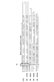
- MGTA values (advance time): 0ms / 0.25ms / 0.5ms. Specifically, 0 ms means that MG is not shifted forward. 0.5 ms is used when Frequency Range 1 (FR1) is included. 0.25 ms is used when the measurement target cell is only FR2 (only in the case of Per-FR gap for FR2).
- MG The following two types of MG are defined.
- Per-UE gap (same as LTE MG) ⁇ Per-FR gap
- LTE MG Long Term Evolution
- Per-FR gap In the Per-UE gap, only one MG can be set to UE 200 regardless of the frequency band of the measurement target cell. Also, data transmission / reception is not possible during MG.
- different MGs can be set for each of LTE and NR for FR1 measurement and for NR for FR2 measurement. For example, while MG is applied for NR FR2 measurement, communication in LTE and NR FR1 can be continued.
- the EN-DC when the EN-DC is executed, it is proposed that when Per-UE gap and MGTA is 0 ms, the timing is adjusted to the reference timing on the MCG side (LTE). Specifically, it has been proposed to start the MG in accordance with the subframe boundary on the LTE side. It is also proposed that, when the EN-DC is executed, if the Per-FR gap for FR1 measurement of the NR and MGTA is 0 ms, the timing is adjusted to the reference timing on the MCG side (LTE).
- FIG. 4 shows the MG when applying MGTA An example of a relationship between a start timing and a reference timing used in a target cell is shown. In FIG. 4, each horizontally long rectangle indicates a subframe or a slot.
- MGTA when MGTA is applied during execution of EN-DC, MG starts from timing T1, which is the middle of the LTE subframe (0.5 ms has elapsed).
- the UE 200 does not have a reference timing (slot boundary) that can be referred to at the timing T1 (another subcarrier interval). In the case of, there is a reference timing that can be referred to at the timing T1).
- SCS subcarrier interval
- the UE 200 can determine the MG start timing according to the measurement target cell for which the cell quality is to be measured (Operation Example 1).
- the UE 200 can determine the start timing based on the type of the reference timing used in the communication node (SN) indicating the MG (Operation Example 2).
- the start timing of the SMTC window set for the cell of FR2 to be measured or the measurement target MG start timing is determined based on a slot boundary of a cell (a cell using FR2 of NR).
- EN-DC is not executed (only LTE primary cell (PCell) operation)
- SMTC window set for the NR cell to be measured or based on the slot boundary of the NR cell
- the start timing of the MG is determined.
- MG start timing is determined using the result of SFN and Frame timing timing difference measurement (SFTD measurement) in which LTE eNB acquires the SSB transmission timing of the NR cell to be measured. May be done.
- SFTD measurement Frame timing timing difference measurement
- MGTA When MGTA is applied, a position shifted from the SMTC start timing by 1 to 4 slots ahead may be used as the MG start timing.
- the number of slots to be shifted is preferably changed according to the subcarrier interval (SCS). For example, a 0.5 ms MGTA is applied, and one slot can be used when the measurement target cell (NR cell) has a 30 kHz spacing, and two slots can be used when the measurement target cell (NR cell) has a 60 kHz spacing.
- SCS subcarrier interval
- the operation when operating as a standalone (SA) without dual connectivity, the operation may be the same as when EN-DC is not running. Further, when the measurement target cell is an LTE cell, the MG start timing may be determined in accordance with the LTE subframe (1 ms).
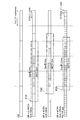
- FIG. 5 shows an example of the MG start timing based on the operation example 1 and the operation example 2. More specifically, FIG. 5 shows the start timing of the MG on the NR side when performing EN-DC.
- the MG start timing (see P10 in the figure) is adjusted to the LTE subframe.
- the MG is 4 ms and the SMTC window is 2 ms.
- the start timing of MG is determined based on the start timing of the SMTC window set for NR or the slot boundary of the NR cell (P20 in the figure). .
- the MG is 4 ms and the SMTC window is 3 ms.
- MGTA is 0.5 ms
- a position where the slot number (1 slot) corresponding to the MGTA is moved forward is set as the MG start timing.
- MGTA is applied, and also in the case of 120 kHz spacing, the start timing of MG is determined based on the start timing of the SMTC window set for NR or the slot boundary of the NR cell (P30 in the figure) ). In this case, MG is 3.5ms and SMTC window is 3ms.
- MGTA is 0.25 ms
- a position where the number of slots (two slots) corresponding to the MGTA is moved forward is the MG start timing.
- the start timing of MG is adjusted to the reference timing (slot boundary) of the cell on the SCG side.
- the start timing of the MG is adjusted to the timing on the LTE side.
- MGTA when MGTA is applied, a position shifted from the SMTC start timing by 1 to 4 slots ahead may be used as the MG start timing.
- the start timing of the MG may be determined based on the timing of the LTE subframe.
- the start timing of the MG is determined based on the timing of the LTE subframe, but the slot corresponding to the spacing of the subcarrier used in the NR cell is determined from the start timing.
- a position moved forward by a number is set as the MG start timing.
- the position where the slot number (1 slot) corresponding to the MGTA is moved forward is the MG start timing.
- the start timing of MG is the start timing of the SMTC window set for NR, or the slot boundary of the NR cell. (P30 in the figure).
- MGTA is 0.25 ms
- a position where the number of slots (two slots) corresponding to the MGTA is moved forward is the MG start timing.
- the OFDM symbol boundary is You may refer to it.
- FIG. 6 shows a configuration example of an OFDM symbol. Specifically, FIG. 6 shows an example of a 14 OFDM symbol. When the SCS has a spacing of 15 kHz, a boundary between the symbol # 6 and the symbol # 7 may be used as the reference timing.
- UE 200 applies MG start timing according to the type of reference timing used in the target cell. Therefore, it is possible to reliably avoid a state in which the reference timing that can be referred to for determining the MG start timing cannot be referred to. Thereby, it is possible to prevent the start timing accuracy of the MG in the UE 200 from being reduced.
- the start timing accuracy of the MG can be maintained.
- the UE 200 can apply the MG start timing according to the type of the reference timing used for the measurement target cell for which the cell quality is to be measured. Further, in the present embodiment, the MG start timing according to the SMTC (predetermined measurement scheme) cycle set in the measurement target cell or the subframe cycle set in the measurement target cell can be applied.
- SMTC predetermined measurement scheme
- the UE 200 can apply the start timing according to the type of the reference timing used in the communication node (SN or the like) indicating the MG.
- the operation example 1 and the operation example 2 described in the above embodiment may be combined.
- the operation example 1 may be applied to the stand-alone operation
- the operation example 2 may be applied to the execution of the EN-DC.
- the MG start timing may be adjusted to the frame timing or subframe timing used in the NR cell.
- each functional block may be realized using one device physically or logically coupled, or directly or indirectly (for example, two or more devices physically or logically separated). , Wired, wireless, etc.), and may be implemented using these multiple devices.
- the functional block may be realized by combining one device or the plurality of devices with software.
- Functions include: judgment, decision, judgment, calculation, calculation, processing, derivation, investigation, search, confirmation, reception, transmission, output, access, resolution, selection, selection, establishment, comparison, assumption, expectation, deemed, notification ( broadcasting), notifying, communicating, forwarding, configuring, reconfiguring, allocating, mapping, assigning, etc., but not limited to these .
- a functional block (configuration unit) that makes transmission function is called a transmitting unit (transmitting unit) or a transmitter (transmitter).
- the realization method is not particularly limited.
- FIG. 7 is a diagram illustrating an example of a hardware configuration of the UE 200.
- the device may be configured as a computer device including a processor 1001, a memory 1002, a storage 1003, a communication device 1004, an input device 1005, an output device 1006, a bus 1007, and the like.
- the term “apparatus” can be read as a circuit, a device, a unit, or the like.
- the hardware configuration of the device may be configured to include one or more devices illustrated in the drawing, or may be configured without including some devices.
- Each functional block of the device is realized by any hardware element of the computer device or a combination of the hardware components.
- the functions of the device are controlled by reading predetermined software (program) on hardware such as the processor 1001 and the memory 1002, so that the processor 1001 performs an operation and controls communication by the communication device 1004, It is realized by controlling at least one of reading and writing of data in the storage 1002 and the storage 1003.
- predetermined software program
- the processor 1001 performs an operation and controls communication by the communication device 1004, It is realized by controlling at least one of reading and writing of data in the storage 1002 and the storage 1003.
- the processor 1001 controls the entire computer by operating an operating system, for example.
- the processor 1001 may be configured by a central processing unit (CPU) including an interface with a peripheral device, a control device, an arithmetic device, a register, and the like.
- CPU central processing unit
- the processor 1001 reads out a program (program code), a software module, data, and the like from at least one of the storage 1003 and the communication device 1004 to the memory 1002, and executes various processes according to these.
- program program code
- a program that causes a computer to execute at least a part of the operation described in the above embodiment is used.
- the various processes described above may be executed by one processor 1001 or may be executed simultaneously or sequentially by two or more processors 1001.
- Processor 1001 may be implemented by one or more chips.
- the program may be transmitted from a network via a telecommunication line.
- the memory 1002 is a computer-readable recording medium, and includes, for example, at least one of Read Only Memory (ROM), Erasable Programmable ROM (EPROM), Electrically Erasable Programmable ROM (EEPROM), Random Access Memory (RAM), and the like. May be done.
- the memory 1002 may be called a register, a cache, a main memory (main storage device), or the like.
- the memory 1002 can store programs (program codes), software modules, and the like that can execute the method according to an embodiment of the present disclosure.
- the storage 1003 is a computer-readable recording medium, for example, an optical disc such as a Compact Disc ROM (CD-ROM), a hard disc drive, a flexible disc, a magneto-optical disc (for example, a compact disc, a digital versatile disc, a Blu-ray (Registered trademark) disk, a smart card, a flash memory (for example, a card, a stick, a key drive), a floppy (registered trademark) disk, and a magnetic strip.
- the storage 1003 may be called an auxiliary storage device.
- the above-described recording medium may be, for example, a database including at least one of the memory 1002 and the storage 1003, a server, or another appropriate medium.
- the communication device 1004 is hardware (transmitting / receiving device) for performing communication between computers via at least one of a wired network and a wireless network, and is also referred to as, for example, a network device, a network controller, a network card, a communication module, and the like.
- the communication device 1004 includes a high-frequency switch, a duplexer, a filter, a frequency synthesizer, and the like, for example, in order to realize at least one of frequency division duplex (Frequency Division Duplex: FDD) and time division duplex (Time Division Duplex: TDD). May be configured.
- FDD Frequency Division Duplex
- TDD Time Division Duplex
- the input device 1005 is an input device (for example, a keyboard, a mouse, a microphone, a switch, a button, a sensor, and the like) that receives an external input.
- the output device 1006 is an output device that performs output to the outside (for example, a display, a speaker, an LED lamp, and the like). Note that the input device 1005 and the output device 1006 may have an integrated configuration (for example, a touch panel).
- the devices such as the processor 1001 and the memory 1002 are connected by a bus 1007 for communicating information.
- the bus 1007 may be configured using a single bus, or may be configured using a different bus for each device.
- the device includes hardware such as a microprocessor, a digital signal processor (DSP), an application specific integrated circuit (ASIC), a programmable logic device (PLD), and a field programmable gate array (FPGA). And some or all of the functional blocks may be implemented by the hardware.
- the processor 1001 may be implemented using at least one of these pieces of hardware.
- notification of information is not limited to the aspect / embodiment described in the present disclosure, and may be performed using another method.
- information notification includes physical layer signaling (for example, Downlink Control Information (DCI), Uplink Control Information (UCI), upper layer signaling (for example, RRC signaling, Medium Access Control (MAC) signaling, and broadcast information (Master Information Block)).
- DCI Downlink Control Information
- UCI Uplink Control Information
- RRC signaling for example, RRC signaling, Medium Access Control (MAC) signaling, and broadcast information (Master Information Block)
- MIB System Information Block
- SIB System Information Block
- RRC signaling may be called an RRC message, for example, RRC connection setup (RRC Connection Setup). ) Message, an RRC connection reconfiguration message, etc.
- LTE Long Term Evolution
- LTE-A LTE-Advanced
- SUPER 3G IMT-Advanced
- 4th generation mobile communication system 4th generation mobile communication system
- 5G 5 th generation mobile communication system
- Future Radio Access FAA
- New Radio NR
- W-CDMA registered trademark
- GSM registered trademark
- CDMA2000 Code Division Multiple Access
- UMB Ultra Mobile Broadband
- IEEE 802.11 Wi-Fi (registered trademark))
- IEEE 802.16 WiMAX (R)
- IEEE 802.20 Ultra-WideBand (UWB), Bluetooth (R), and other appropriate systems
- at least a next generation system based on these systems It may be applied to one.
- a plurality of systems may be combined (for example, a combination of at least one of LTE and LTE-A with 5G) and applied.
- the specific operation described as being performed by the base station in the present disclosure may be performed by its upper node (upper node) in some cases.
- various operations performed for communication with a terminal are performed by the base station and other network nodes other than the base station (eg, MME or It is clear that this can be done by at least one of S-GW or the like (but not limited to these).
- MME Mobility Management Entity
- S-GW Packet Control Function
- Information and signals can be output from an upper layer (or lower layer) to a lower layer (or upper layer). Input and output may be performed via a plurality of network nodes.
- the input / output information may be stored in a specific place (for example, a memory) or may be managed using a management table. Information that is input and output can be overwritten, updated, or appended. The output information may be deleted. The input information may be transmitted to another device.
- the determination may be made based on a value (0 or 1) represented by one bit, a Boolean value (Boolean: true or false), or a comparison of numerical values (for example, a predetermined value). Value).
- Each aspect / embodiment described in the present disclosure may be used alone, may be used in combination, or may be used by switching with execution. Further, the notification of the predetermined information (for example, the notification of “X”) is not limited to being explicitly performed, and is performed implicitly (for example, not performing the notification of the predetermined information). Is also good.
- software, instructions, information, and the like may be transmitted and received via a transmission medium.
- a transmission medium For example, if the software uses at least one of wired technology (coaxial cable, fiber optic cable, twisted pair, digital subscriber line (DSL), etc.) and wireless technology (infrared, microwave, etc.), When transmitted from a server, or other remote source, at least one of these wired and / or wireless technologies is included within the definition of a transmission medium.
- the information, signals, etc. described in this disclosure may be represented using any of a variety of different technologies.
- data, instructions, commands, information, signals, bits, symbols, chips, etc. that can be referred to throughout the above description are not limited to voltages, currents, electromagnetic waves, magnetic or magnetic particles, light fields or photons, or any of these. May be represented by a combination of
- At least one of the channel and the symbol may be a signal (signaling).
- the signal may be a message.
- a component carrier (Component @ Carrier: CC) may be called a carrier frequency, a cell, a frequency carrier, or the like.
- system and “network” used in this disclosure are used interchangeably.
- the information, parameters, and the like described in the present disclosure may be expressed using an absolute value, may be expressed using a relative value from a predetermined value, or may be expressed using another corresponding information. May be represented.
- the radio resource may be indicated by an index.
- the names used for the above parameters are not limiting in any way. Further, equations and the like using these parameters may differ from those explicitly disclosed in the present disclosure.
- the various channels (eg, PUCCH, PDCCH, etc.) and information elements can be identified by any suitable name, so that the various names assigned to these various channels and information elements are limited in any way to the limited names is not.
- base station Base @ Station: BS
- wireless base station fixed station
- NodeB NodeB
- eNodeB eNodeB
- gNodeB gNodeB
- a base station may also be referred to as a macro cell, a small cell, a femto cell, a pico cell, or the like.
- a base station can accommodate one or more (eg, three) cells (also called sectors). If the base station accommodates a plurality of cells, the entire coverage area of the base station can be partitioned into a plurality of smaller areas, each smaller area being a base station subsystem (eg, a small indoor base station (RemoteReRadio Radio)). Head: RRH) can also provide communication services.
- a base station subsystem eg, a small indoor base station (RemoteReRadio Radio)
- Head: RRH can also provide communication services.
- cell refers to a base station that provides communication services in this coverage and / or a portion or the entire coverage area of at least one of the base station subsystems.
- MS Mobile station
- UE User equipment
- a mobile station can be a subscriber station, mobile unit, subscriber unit, wireless unit, remote unit, mobile device, wireless device, wireless communication device, remote device, mobile subscriber station, access terminal, mobile terminal, wireless terminal, by one of ordinary skill in the art. It may also be called a terminal, a remote terminal, a handset, a user agent, a mobile client, a client, or some other suitable term.
- At least one of the base station and the mobile station may be called a transmitting device, a receiving device, a communication device, or the like.
- at least one of the base station and the mobile station may be a device mounted on the mobile unit, the mobile unit itself, or the like.
- the moving object may be a vehicle (for example, a car, an airplane, etc.), an unmanned moving object (for example, a drone, a self-driving car, etc.), or a robot (maned or unmanned). ).
- at least one of the base station and the mobile station includes a device that does not necessarily move during a communication operation.
- at least one of the base station and the mobile station may be an Internet of Things (IoT) device such as a sensor.
- IoT Internet of Things
- the base station in the present disclosure may be read as a mobile station (user terminal, hereinafter the same).
- communication between a base station and a mobile station is replaced with communication between a plurality of mobile stations (for example, it may be called Device-to-Device (D2D), Vehicle-to-Everything (V2X), etc.).
- D2D Device-to-Device
- V2X Vehicle-to-Everything
- Each aspect / embodiment of the present disclosure may be applied to the configuration.
- the mobile station may have the function of the base station.
- words such as “up” and “down” may be read as words corresponding to communication between terminals (for example, “side”).
- an uplink channel, a downlink channel, and the like may be replaced with a side channel.
- the mobile station in the present disclosure may be read as a base station.
- the function that the mobile station has may be provided in the base station.
- connection means any direct or indirect connection or coupling between two or more elements that It may include the presence of one or more intermediate elements between the two elements "connected” or “coupled.”
- the coupling or connection between the elements may be physical, logical, or a combination thereof.
- connection may be read as “access”.
- two elements may be implemented using at least one of one or more electrical wires, cables, and printed electrical connections, and as some non-limiting and non-exhaustive examples, in the radio frequency domain. , Can be considered “connected” or “coupled” to each other, such as by using electromagnetic energy having wavelengths in the microwave and light (both visible and invisible) regions.
- the reference signal may be abbreviated as Reference Signal (RS), or may be referred to as a pilot depending on the standard applied.
- RS Reference Signal
- any reference to elements using designations such as "first,” “second,” etc., as used in the present disclosure, does not generally limit the quantity or order of those elements. These designations may be used in the present disclosure as a convenient way to distinguish between two or more elements. Thus, a reference to a first and second element does not mean that only two elements may be employed therein, or that the first element must somehow precede the second element.
- the term “A and B are different” may mean that “A and B are different from each other”.
- the term may mean that “A and B are different from C, respectively”.
- Terms such as “separate”, “coupled” and the like may be interpreted similarly to "different”.
- Wireless communication system 100 eNB 110 gNB 200 UE 210 transmitter 220 receiver 230 controller 1001 processor 1002 memory 1003 storage 1004 communication device 1005 input device 1006 output device 1007 bus
Abstract
This user equipment controls the start timing of a measurement gap. Specifically, the user equipment applies the start timing of a measurement gap that corresponds to the type of reference timing used in a given cell.
Description
本発明は、ユーザ装置に関する。
<< The present invention relates to a user device.
3rd Generation Partnership Project(3GPP)は、Long Term Evolution(LTE)を仕様化し、LTEのさらなる高速化を目的としてLTE-Advanced(以下、LTE-Advancedを含めてLTEという)を仕様化している。また、3GPPでは、さらに、5G New Radio(NR)、或いはNext Generation(NG)などと呼ばれるLTEの後継システムの仕様が検討されている。
The 3rd Generation Partnership Project (3GPP) specifies Long Term Evolution (LTE), and specifies LTE-Advanced (hereafter LTE-Advanced including LTE-Advanced) for the purpose of further increasing LTE speed. In 3GPP, the specification of a successor system of LTE called 5G New Radio (NR) or Next Generation (NG) is under study.
NRでは、LTEと同様に、ユーザ装置(User Equipment, UE)が、無線周波数(RF)のチューニング(RF retuning)が必要な測定を実行する場合、RF retuningのために一切データ及び制御信号が送受信されない期間として、測定ギャップ(MG)を設定できる。
In NR, as in LTE, when a user apparatus (User Equipment, UE) performs a measurement that requires radio frequency (RF) tuning (RF retuning), any data and control signals are transmitted and received for RF retuning. The measurement gap (MG) can be set as a period not to be performed.
また、SS/PBCH block (SSB)-based RRM Measurement Timing Configuration(SMTC)の開始タイミングと、MGの開始タイミングとが同一の場合、MGのRF retuningに要する時間とSMTCとが重複し、SMTCに従ったSSBを測定できない状態が発生し得る。そこで、MGの開始タイミングを前倒しする機能(Measurement Gap Timing Advance (MGTA))が導入されている。
If the start timing of the SS / PBCH block (SSB) -based RRM Measurement Timing Configuration (SMTC) is the same as the start timing of the MG, the time required for the RF retuning of the MG overlaps with the SMTC, and the SMTC is followed. A state may occur in which the measured SSB cannot be measured. Therefore, a function (Measurement Gap Timing Advance (MGTA)) that advances the MG start timing is introduced.
MGTAによる前倒し時間の値としては、0ms(前倒ししない)、0.25ms及び0.5msが規定されている。また、E-UTRA-NR Dual Connectivity(EN-DC)におけるMGの開始タイミングの設定についても提案されている(非特許文献1参照)。
As the value of the advance time by MGTA, 0 ms (do not advance), 0.25 ms, and 0.5 ms are specified. In addition, setting of MG start timing in E-UTRA-NR Dual Connectivity (EN-DC) has been proposed (see Non-Patent Document 1).
しかしながら、MGTAに従ってMGの開始タイミングを前倒しする場合など、MGの開始タイミングを決定するために参照し得る基準タイミング(例えば、サブフレームを構成するスロットの境界)が存在しないケースが発生し得る。
However, when the start timing of the MG is moved forward according to the MGTA, a case may occur in which there is no reference timing (for example, a boundary between slots constituting a subframe) that can be referred to for determining the start timing of the MG.
例えば、EN-DCにおいて0.5msのMGTAが適用される場合、LTEのサブフレーム(1ms)の中間地点(0.5ms)からMGが開始することとなるが、NRのサブキャリア間隔(例えば、15kHz)によっては、UEは、前倒しされたMGの開始タイミングを決定するために参照し得る基準タイミングを得ることができない。
For example, when a 0.5 ms MGTA is applied in EN-DC, the MG starts from the middle point (0.5 ms) of the LTE subframe (1 ms), but the NR subcarrier interval (for example, 15 kHz) In some cases, the UE cannot obtain a reference timing that can be referred to in order to determine the start timing of the advanced MG.
このため、UEにおけるMGの開始タイミングを適切に決定できない、もしくはMGの開始タイミング精度が低下することが懸念される。
た め Therefore, there is a concern that the start timing of the MG in the UE cannot be appropriately determined, or that the accuracy of the MG start timing decreases.
そこで、本発明は、このような状況に鑑みてなされたものであり、測定ギャップ(MG)の開始タイミングが異なる場合でも、MGの開始タイミング精度を維持し得るユーザ装置の提供を目的とする。
Accordingly, the present invention has been made in view of such a situation, and an object of the present invention is to provide a user apparatus that can maintain the start timing accuracy of a measurement gap (MG) even when the start timing of the MG differs.
本発明の一態様は、ユーザ装置(UE200)であって、測定ギャップの開始タイミングを制御する制御部(制御部230)を備え、前記制御部は、対象となるセルにおいて用いられている基準タイミングの種類に応じた前記開始タイミングを適用する。
One embodiment of the present invention is a user apparatus (UE200), which includes a control unit (control unit 230) that controls a start timing of a measurement gap, wherein the control unit uses a reference timing used in a target cell. The start timing according to the type is applied.
以下、実施形態を図面に基づいて説明する。なお、同一の機能や構成には、同一または類似の符号を付して、その説明を適宜省略する。
Hereinafter, embodiments will be described with reference to the drawings. Note that the same functions and configurations are denoted by the same or similar reference numerals, and description thereof will be omitted as appropriate.
(1)無線通信システムの全体概略構成
図1は、本実施形態に係る無線通信システム10の全体概略構成図である。無線通信システム10は、Long Term Evolution(LTE)及び5G New Radio(NR)に従った無線通信システムであり、無線基地局100(以下、eNB100)、無線基地局110(以下、gNB110)及びユーザ装置200(以下、UE200)を含む。なお、gNB及びUEの数を含む無線通信システム10の具体的な構成は、図1に示した例に限定されない。 (1) Overall Schematic Configuration of Wireless Communication System FIG. 1 is an overall schematic configuration diagram of awireless communication system 10 according to the present embodiment. The radio communication system 10 is a radio communication system according to Long Term Evolution (LTE) and 5G New Radio (NR), and includes a radio base station 100 (hereinafter, eNB100), a radio base station 110 (hereinafter, gNB110), and a user device. 200 (hereinafter, UE200). The specific configuration of the wireless communication system 10 including the number of gNBs and UEs is not limited to the example shown in FIG.
図1は、本実施形態に係る無線通信システム10の全体概略構成図である。無線通信システム10は、Long Term Evolution(LTE)及び5G New Radio(NR)に従った無線通信システムであり、無線基地局100(以下、eNB100)、無線基地局110(以下、gNB110)及びユーザ装置200(以下、UE200)を含む。なお、gNB及びUEの数を含む無線通信システム10の具体的な構成は、図1に示した例に限定されない。 (1) Overall Schematic Configuration of Wireless Communication System FIG. 1 is an overall schematic configuration diagram of a
eNB100は、LTEに従った無線基地局であり、一つまたは複数のセルを形成する。gNB110は、5Gに従った無線基地局であり、一つまたは複数のセルを形成する。当該セルによってMaster Cell Group(MCG)及びSecondary Cell Group(SCG)を構成できる。
ENB 100 is a radio base station according to LTE, and forms one or a plurality of cells. The gNB 110 is a wireless base station according to 5G and forms one or a plurality of cells. The cell can constitute a Master Cell Group (MCG) and a Secondary Cell Group (SCG).
eNB100とUE200とは、一つまたは複数のキャリアを用いて、LTEに従った無線通信を実行する。また、gNB110とUE200とは、一つまたは複数のキャリアを用いて、5Gに従った無線通信を実行する。
The eNB 100 and the UE 200 execute wireless communication according to LTE using one or a plurality of carriers. In addition, the gNB 110 and the UE 200 execute wireless communication according to 5G using one or a plurality of carriers.
eNB100、gNB110及びUE200は、複数のアンテナ素子から送信される無線信号を制御することによって、より指向性の高いビームを生成するMassive MIMO、複数のコンポーネントキャリア(CC)を用いるキャリアアグリゲーション(CA)、及び複数のNG-RAN NodeとUEとの間においてコンポーネントキャリアを同時送信するデュアルコネクティビティ(DC)などに対応することができる。
eNB100, gNB110 and UE200 control a radio signal transmitted from a plurality of antenna elements to generate a more highly directive beam Massive MIMO, a carrier aggregation (CA) using a plurality of component carriers (CC), And dual connectivity (DC) for simultaneously transmitting component carriers between a plurality of NG-RAN nodes and the UE.
(2)無線通信システムの機能ブロック構成
次に、無線通信システム10の機能ブロック構成について説明する。具体的には、UE200の機能ブロック構成について説明する。 (2) Functional Block Configuration of Wireless Communication System Next, a functional block configuration of thewireless communication system 10 will be described. Specifically, a functional block configuration of UE 200 will be described.
次に、無線通信システム10の機能ブロック構成について説明する。具体的には、UE200の機能ブロック構成について説明する。 (2) Functional Block Configuration of Wireless Communication System Next, a functional block configuration of the
図2は、UE200の機能ブロック構成図である。図2に示すように、UE200は、送信部210、受信部220及び制御部230を備える。
FIG. 2 is a functional block configuration diagram of the UE 200. As shown in FIG. 2, the UE 200 includes a transmission unit 210, a reception unit 220, and a control unit 230.
送信部210は、NRに従った上りリンク信号(UL信号)を送信する。
Transmission section 210 transmits an uplink signal (UL signal) according to NR.
受信部220は、NRに従った下りリンク信号(DL信号)を受信する。特に、本実施形態では、受信部220は、参照信号(RS)を受信する。具体的には、受信部220は、Radio Link Monitoring-RS(RLM-RS)などを受信する。
(4) The receiving unit 220 receives a downlink signal (DL signal) according to the NR. In particular, in the present embodiment, the receiving unit 220 receives a reference signal (RS). More specifically, the receiving unit 220 receives Radio Link Monitoring R (RLM-RS) and the like.
制御部230は、送信部210によって送信されるUL信号、及び受信部220によって受信されるDL信号に関する制御を実行する。
The control unit 230 performs control on the UL signal transmitted by the transmission unit 210 and the DL signal received by the reception unit 220.
また、本実施形態では、制御部230は、eNB100またはgNB110から送信されるキャリア(ビーム)に関する測定を実行する。具体的には、制御部230は、測定ギャップを利用してセル品質の測定を実行する。
In addition, in the present embodiment, the control unit 230 performs measurement on a carrier (beam) transmitted from the eNB 100 or the gNB 110. Specifically, control section 230 performs measurement of cell quality using the measurement gap.
測定ギャップ(MG)とは、所望する無線周波数(RF)の品質などの測定のために、一切のデータ及び制御信号が送受信されない期間と理解される。一例として、無線周波数(RF)のチューニング(RF retuning)のために一切のデータ及び制御信号が送受信されない期間である。具体的には、MGでは、データ(Physical Downlink Shared Channel (PDSCH)及びPhysical Uplink Shared Channel (PUSCH))及び制御信号(Physical Downlink Control Channel (PDCCH)及びPhysical Uplink Control Channel (PUCCH))が送受信されない。
Measurement gap (MG) is understood as the period during which no data and control signals are transmitted or received for the purpose of measuring the desired radio frequency (RF) quality or the like. An example is a period in which no data and control signals are transmitted or received due to radio frequency (RF) tuning (RF retuning). Specifically, in the MG, data (Physical Downlink Shared Channel (PDSCH) and Physical Uplink Shared Channel (PUSCH)) and control signals (Physical Downlink Control Channel (PDCCH) and Physical Uplink Control Channel (PUCCH)) are not transmitted and received.
また、制御部230は、SS/PBCH block (SSB)-based RRM Measurement Timing Configuration(SMTC)に従った測定を実行する。さらに、本実施形態では、制御部230は、MGの開始タイミングを前倒しする機能、具体的には、MGTAに対応している。MGTAに基づく動作については、さらに後述する。
{Control unit 230 also performs measurement according to SS / PBCH {block} (SSB) -based {RRM} Measurement {Timing} Configuration (SMTC). Further, in the present embodiment, the control unit 230 corresponds to a function of moving the MG start timing ahead, specifically, MGTA. The operation based on MGTA will be further described later.
制御部230は、MGの開始タイミングを制御する。具体的には、制御部230は、対象となるセルにおいて用いられている基準タイミングの種類に応じたMGの開始タイミングを適用する。
(4) The control unit 230 controls the start timing of the MG. Specifically, the control unit 230 applies the MG start timing according to the type of the reference timing used in the target cell.
より具体的には、制御部230は、セル品質の測定の対象となる測定対象セルに用いられている基準タイミングの種類に応じたMGの開始タイミングを適用する。基準タイミングは、当該測定対象セルのサブフレーム周期(1ms)、或いは当該サブフレームを構成するスロット(例えば、0.25ms, 0.5ms)から導き出される。スロットは、単位時間またはTTIと呼ばれてもよい。
More specifically, the control unit 230 applies the MG start timing according to the type of the reference timing used for the measurement target cell for which the cell quality is to be measured. The reference timing is derived from a subframe period (1 ms) of the measurement target cell or a slot (for example, 0.25 ms, 0.5 ms) configuring the subframe. A slot may be called a unit time or TTI.
すなわち、制御部230は、当該スロットの境界に合わせるようにMGの開始タイミングを決定できる。
That is, the control unit 230 can determine the start timing of the MG so as to match the boundary of the slot.
また、制御部230は、測定対象セルにおいて設定されているSMTC(所定の測定方式)の周期に応じたMGの開始タイミングを適用することもできる。具体的には、制御部230は、測定したいFrequency Range 2(FR2)のセル向けに設定されたSMTCウィンドウの開始タイミングにMGの開始タイミングを合わせる。
The control unit 230 can also apply the MG start timing according to the SMTC (predetermined measurement method) cycle set in the measurement target cell. Specifically, control section 230 adjusts the start timing of the MG to the start timing of the SMTC window set for the cell of Frequency RangeFR2 (FR2) to be measured.
さらに、制御部230は、測定対象セルにおいて設定されているサブフレームの周期に応じた開始タイミングを適用してもよい。特に、測定対象セルがLTEの場合、このような方法を適用することが好ましい。
Furthermore, the control unit 230 may apply a start timing according to the cycle of the subframe set in the measurement target cell. In particular, when the cell to be measured is LTE, it is preferable to apply such a method.
或いは、制御部230は、MGを指示する通信ノードにおいて用いられている基準タイミングの種類に応じた開始タイミングを適用することもできる。具体的には、制御部230は、EN-DC実行時におけるPer-FR gap for FR2(詳細については後述)など、MGを指示する通信ノードであるSecondary Node(SN)から設定されるMGに関しては、SCG側の基準タイミング(スロット境界)に合わせる。本実施形態では、EN-DC実行時におけるgNB110がSNに該当する。
Alternatively, the control unit 230 can apply a start timing according to the type of reference timing used in the communication node instructing the MG. Specifically, the control unit 230 determines the MG set from the Secondary Node (SN) which is the communication node instructing the MG, such as Per-FR {gap for FR2 (details will be described later) when the EN-DC is executed. To the reference timing (slot boundary) on the SCG side. In the present embodiment, the gNB 110 when executing the EN-DC corresponds to the SN.
(3)無線通信システムの動作
次に、無線通信システム10の動作について説明する。具体的には、UE200によるMGの開始タイミングの決定動作について説明する。 (3) Operation of Wireless Communication System Next, the operation of thewireless communication system 10 will be described. Specifically, an operation of determining the MG start timing by UE 200 will be described.
次に、無線通信システム10の動作について説明する。具体的には、UE200によるMGの開始タイミングの決定動作について説明する。 (3) Operation of Wireless Communication System Next, the operation of the
(3.1)MGTAの概要及び従来のMGの開始タイミング例
まず、図3及び図4を参照して、MGTAの概要、及び従来のMGの開始タイミング例について説明する。 (3.1) Overview of MGTA and Example of Start Timing of Conventional MG First, an overview of MGTA and an example of start timing of the conventional MG will be described with reference to FIGS. 3 and 4.
まず、図3及び図4を参照して、MGTAの概要、及び従来のMGの開始タイミング例について説明する。 (3.1) Overview of MGTA and Example of Start Timing of Conventional MG First, an overview of MGTA and an example of start timing of the conventional MG will be described with reference to FIGS. 3 and 4.
図3は、MGTAの動作概略図である。具体的には、図3は、SMTC(図中のSSB、左傾斜線部分)の開始タイミング、及びMG(右傾斜線部分)の開始タイミングを示す。図3では、MGが4msである例を示す。
Figure 3 is a schematic diagram of the operation of MGTA. Specifically, FIG. 3 shows the start timing of SMTC (SSB in the figure, left inclined line portion) and the start timing of MG (right inclined line portion). FIG. 3 shows an example in which MG is 4 ms.
図3の上側では、MGの開始タイミングと、SMTCの開始タイミングとが一致しており、つまり、同時であり、MGとSMTCとが時間軸上において重複している。このような場合、MGの開始タイミングと、SMTCの開始タイミングとのが同じであるため、MGのRF retuning時間がSMTCの時間と被り、SMTC内のSSBを測定できないケースが発生し得る。
で は In the upper part of FIG. 3, the start timing of the MG and the start timing of the SMTC coincide, that is, at the same time, and the MG and the SMTC overlap on the time axis. In such a case, since the start timing of the MG and the start timing of the SMTC are the same, a case may occur where the RF retuning time of the MG overlaps with the time of the SMTC, and the SSB in the SMTC cannot be measured.
図3の下側では、このようなMGとSMTCとの重複を回避するため、MGの開始タイミングを時間的に前方にずらす、つまり、前倒しするMGTAが導入されている。
の 下 In the lower part of FIG. 3, in order to avoid such overlap between the MG and the SMTC, an MGTA that shifts the start timing of the MG temporally forward, that is, moves forward is introduced.
MGTAの値(前倒し時間)は、0ms/0.25ms/0.5msの3種類である。具体的には、0msはMGを前方にずらさないことを意味する。0.5msは、Frequency Range 1(FR1)を含む場合に用いられる。0.25msは、測定対象セルがFR2のみの場合に用いられる(Per-FR gap for FR2の場合のみ)。
There are three MGTA values (advance time): 0ms / 0.25ms / 0.5ms. Specifically, 0 ms means that MG is not shifted forward. 0.5 ms is used when Frequency Range 1 (FR1) is included. 0.25 ms is used when the measurement target cell is only FR2 (only in the case of Per-FR gap for FR2).
また、MGとしては、以下の2種類が規定されている。
MGThe following two types of MG are defined.
・Per-UE gap(LTEのMGと同様)
・Per-FR gap
Per-UE gapでは、測定対象セルの周波数帯に関係なく、UE200に設定できるMGは1つのみである。また、MG中はデータの送受信が不可である。 ・ Per-UE gap (same as LTE MG)
・ Per-FR gap
In the Per-UE gap, only one MG can be set toUE 200 regardless of the frequency band of the measurement target cell. Also, data transmission / reception is not possible during MG.
・Per-FR gap
Per-UE gapでは、測定対象セルの周波数帯に関係なく、UE200に設定できるMGは1つのみである。また、MG中はデータの送受信が不可である。 ・ Per-UE gap (same as LTE MG)
・ Per-FR gap
In the Per-UE gap, only one MG can be set to
Per-FR gapでは、LTE及びNRのFR1測定向け、及びNRのFR2測定向けのそれぞれに対して、異なるMGを設定できる。例えば、NRのFR2測定向けにMGが適用されている間、LTE及びNRのFR1での通信は継続できる。
In {Per-FR} gap, different MGs can be set for each of LTE and NR for FR1 measurement and for NR for FR2 measurement. For example, while MG is applied for NR FR2 measurement, communication in LTE and NR FR1 can be continued.
NRでは、MGの開始タイミングについて幾つかの内容が提案されている(例えば、上述した非特許文献1)。
In NR, some contents are proposed for the MG start timing (for example, the above-mentioned Non-Patent Document 1).
例えば、EN-DC実行時では、Per-UE gapであって、MGTAが0msの場合、MCG側(LTE)の基準タイミングに合わせることが提案されている。具体的には、LTE側のサブフレーム境界に合わせてMGを開始することが提案されている。また、EN-DC実行時では、NRのFR1測定向けのPer-FR gapであって、MGTAが0msの場合、MCG側(LTE)の基準タイミングに合わせることも提案されている。
For example, when the EN-DC is executed, it is proposed that when Per-UE gap and MGTA is 0 ms, the timing is adjusted to the reference timing on the MCG side (LTE). Specifically, it has been proposed to start the MG in accordance with the subframe boundary on the LTE side. It is also proposed that, when the EN-DC is executed, if the Per-FR gap for FR1 measurement of the NR and MGTA is 0 ms, the timing is adjusted to the reference timing on the MCG side (LTE).
一方、以下のようなケースでは、MGの開始タイミングの決定方法が明確ではない。
On the other hand, in the following cases, it is not clear how to determine the MG start timing.
・EN-DC実行時であって、NRのFR2測定向けのPer-FR gapの適用時
・デュアルコネクティビティではないスタンドアロン(SA)運用時
・MGTAの適用時
図4は、MGTAの適用時におけるMGの開始タイミングと、対象となるセルにおいて用いられている基準タイミングとの関係例を示す。図4において、横長の長方形それぞれは、サブフレームまたはスロットを示す。 -When executing the EN-DC and applying the Per-FR gap for FR2 measurement of NR-When operating standalone (SA) that is not dual connectivity-When applying MGTA Figure 4 shows the MG when applying MGTA An example of a relationship between a start timing and a reference timing used in a target cell is shown. In FIG. 4, each horizontally long rectangle indicates a subframe or a slot.
図4に示すように、特に、EN-DC実行時において、MGTAを適用した場合、LTE のサブフレームの中間(0.5ms経過時点)であるタイミングT1からMGが開始することになる。
{As shown in FIG. 4, in particular, when MGTA is applied during execution of EN-DC, MG starts from timing T1, which is the middle of the LTE subframe (0.5 ms has elapsed).
しかしながら、対象となるセルがNRのセルであり、15kHzのサブキャリア間隔(SCS)である場合、UE200は、タイミングT1において参照可能な基準タイミング(スロットの境界)が存在しない(他のサブキャリア間隔の場合は、タイミングT1において参照可能な基準タイミングが存在する)。
However, when the target cell is an NR cell and has a subcarrier interval (SCS) of 15 kHz, the UE 200 does not have a reference timing (slot boundary) that can be referred to at the timing T1 (another subcarrier interval). In the case of, there is a reference timing that can be referred to at the timing T1).
このため、NRのセルの測定であるにも関わらず、全てのMGをLTE側の基準タイミング(サブフレーム)に合わせると、UE200のスペックなどによっては、意図しない、言い換えれば精度の低いタイミングにおいて、MGを開始する可能性がある。これにより、UE200におけるMGの開始タイミング精度が低下し、結果的に無線通信システム10全体としての品質が低下する可能性がある。
For this reason, when all MGs are adjusted to the reference timing (subframe) on the LTE side in spite of the measurement of the NR cell, depending on the specifications of the UE 200, unintended, in other words, at low accuracy timing, May start MG. As a result, the start timing accuracy of the MG in the UE 200 may be reduced, and as a result, the quality of the entire wireless communication system 10 may be reduced.
(3.2)動作例
次に、上述したような課題を解消するUE200の動作例について説明する。UE200は、上述したような課題を解消するため、MGの開始タイミングを適切に設定し、ネットワーク側が意図したタイミングにおいて、正確な周辺セルの品質を測定する。 (3.2) Operation Example Next, an operation example of theUE 200 that solves the above-described problem will be described. In order to solve the above-described problem, the UE 200 appropriately sets the MG start timing, and accurately measures the quality of the neighboring cells at the timing intended by the network side.
次に、上述したような課題を解消するUE200の動作例について説明する。UE200は、上述したような課題を解消するため、MGの開始タイミングを適切に設定し、ネットワーク側が意図したタイミングにおいて、正確な周辺セルの品質を測定する。 (3.2) Operation Example Next, an operation example of the
具体的には、UE200は、セル品質の測定の対象となる測定対象セルに応じたMGの開始タイミングを決定することができる(動作例1)。
Specifically, the UE 200 can determine the MG start timing according to the measurement target cell for which the cell quality is to be measured (Operation Example 1).
また、UE200は、MGを指示する通信ノード(SN)において用いられている基準タイミングの種類に基づいて、開始タイミングを決定することができる(動作例2)。
The UE 200 can determine the start timing based on the type of the reference timing used in the communication node (SN) indicating the MG (Operation Example 2).
以下、各動作例について説明する。
Hereinafter, each operation example will be described.
(3.2.1)動作例1
本動作例では、測定対象セルに用いられている基準タイミングの種類に応じたMGの開始タイミングが適用される。 (3.2.1) Operation example 1
In this operation example, the MG start timing according to the type of the reference timing used for the measurement target cell is applied.
本動作例では、測定対象セルに用いられている基準タイミングの種類に応じたMGの開始タイミングが適用される。 (3.2.1) Operation example 1
In this operation example, the MG start timing according to the type of the reference timing used for the measurement target cell is applied.
具体的には、EN-DC実行時におけるFR2向けのPer-FR gap(Per-FR gap for FR2)については、測定対象のFR2のセル向けに設定されたSMTCウィンドウの開始タイミング、或いは当該測定対象セル(NRのFR2が用いられたセル)のスロット境界に基づいて、MGの開始タイミングが決定される。
Specifically, for the Per-FR gap for FR2 (Per-FR gap for FR2) during the execution of EN-DC, the start timing of the SMTC window set for the cell of FR2 to be measured or the measurement target MG start timing is determined based on a slot boundary of a cell (a cell using FR2 of NR).
EN-DCが実行されていない場合(LTEのプライマリーセル(PCell)運用のみの場合)、測定対象のNRセル向けに設定されたSMTCウィンドウの開始タイミング、或いは当該NRセルのスロット境界に基づいて、MGの開始タイミングが決定される。
If EN-DC is not executed (only LTE primary cell (PCell) operation), based on the start timing of the SMTC window set for the NR cell to be measured, or based on the slot boundary of the NR cell, The start timing of the MG is determined.
なお、基準タイミング(スロット境界)の情報がない場合、LTE eNBが測定対象のNRセルのSSB送信タイミングを取得するSFN and Frame timing difference measurement (SFTD measurement)の結果を用いてMGの開始タイミングが決定されてもよい。
If there is no reference timing (slot boundary) information, MG start timing is determined using the result of SFN and Frame timing timing difference measurement (SFTD measurement) in which LTE eNB acquires the SSB transmission timing of the NR cell to be measured. May be done.
また、MGTAが適用されている場合、SMTCの開始タイミングから1~4スロット前方にシフトした位置をMGの開始タイミングとしてもよい。この場合、シフトするスロット数は、サブキャリア間隔(SCS)に応じて変更されることが好ましい。例えば、0.5msのMGTAが適用され、測定対象セル(NRセル)が30kHzスペーシングの場合は1スロット、測定対象セル(NRセル)が60kHzスペーシングの場合は2スロットとすることができる。
(4) When MGTA is applied, a position shifted from the SMTC start timing by 1 to 4 slots ahead may be used as the MG start timing. In this case, the number of slots to be shifted is preferably changed according to the subcarrier interval (SCS). For example, a 0.5 ms MGTA is applied, and one slot can be used when the measurement target cell (NR cell) has a 30 kHz spacing, and two slots can be used when the measurement target cell (NR cell) has a 60 kHz spacing.
なお、デュアルコネクティビティではないスタンドアロン(SA)運用時については、EN-DCが実行されていない場合と同様に動作してもよい。また、測定対象セルがLTEのセルである場合、LTEのサブフレーム(1ms)に合わせて、MGの開始タイミングが決定されてもよい。
Note that when operating as a standalone (SA) without dual connectivity, the operation may be the same as when EN-DC is not running. Further, when the measurement target cell is an LTE cell, the MG start timing may be determined in accordance with the LTE subframe (1 ms).
図5は、動作例1及び動作例2に基づくMGの開始タイミングの例を示す。具体的には、図5では、EN-DC実行時におけるNR側でのMGの開始タイミングが示されている。
FIG. 5 shows an example of the MG start timing based on the operation example 1 and the operation example 2. More specifically, FIG. 5 shows the start timing of the MG on the NR side when performing EN-DC.
MGTAが適用されておらず、30kHzスペーシングの場合、MGの開始タイミング(図中のP10参照)は、LTEのサブフレームに合わせられる。このケースでは、MGが4ms、SMTCウィンドウが2msである。
In the case where MGTA is not applied and the spacing is 30 kHz, the MG start timing (see P10 in the figure) is adjusted to the LTE subframe. In this case, the MG is 4 ms and the SMTC window is 2 ms.
MGTAが適用されており、30kHzスペーシングの場合、MGの開始タイミングは、NR向けに設定されたSMTCウィンドウの開始タイミング、或いは当該NRセルのスロット境界に基づいて決定される(図中のP20)。このケースでは、MGが4ms、SMTCウィンドウが3msである。
When MGTA is applied and in the case of 30 kHz spacing, the start timing of MG is determined based on the start timing of the SMTC window set for NR or the slot boundary of the NR cell (P20 in the figure). . In this case, the MG is 4 ms and the SMTC window is 3 ms.
この場合(ここでは、MGTAが0.5ms)、当該MGTAに応じたスロット数(1スロット)前倒しした位置がMGの開始タイミングとされる。
In this case (here, MGTA is 0.5 ms), a position where the slot number (1 slot) corresponding to the MGTA is moved forward is set as the MG start timing.
なお、P10及びP20では、Per-UE gapまたはPer-FR gap for FR1が適用されているものとする。
In P10 and P20, it is assumed that Per-UE gap or Per-FR gap for FR1 is applied.
MGTAが適用されており、120kHzスペーシングの場合も、MGの開始タイミングは、NR向けに設定されたSMTCウィンドウの開始タイミング、或いは当該NRセルのスロット境界に基づいて決定される(図中のP30)。このケースでは、MGが3.5ms、SMTCウィンドウが3msである。
MGTA is applied, and also in the case of 120 kHz spacing, the start timing of MG is determined based on the start timing of the SMTC window set for NR or the slot boundary of the NR cell (P30 in the figure) ). In this case, MG is 3.5ms and SMTC window is 3ms.
この場合(ここでは、MGTAが0.25ms)、当該MGTAに応じたスロット数(2スロット)前倒しした位置がMGの開始タイミングとされる。
In this case (here, MGTA is 0.25 ms), a position where the number of slots (two slots) corresponding to the MGTA is moved forward is the MG start timing.
(3.2.2)動作例2
本動作例では、MGを指示する通信ノード(SN)において用いられている基準タイミングの種類に応じた開始タイミングが適用される。 (3.2.2) Operation example 2
In this operation example, the start timing according to the type of the reference timing used in the communication node (SN) indicating the MG is applied.
本動作例では、MGを指示する通信ノード(SN)において用いられている基準タイミングの種類に応じた開始タイミングが適用される。 (3.2.2) Operation example 2
In this operation example, the start timing according to the type of the reference timing used in the communication node (SN) indicating the MG is applied.
具体的には、EN-DC実行時におけるPer-FR gap for FR2など、SNから設定されるMGについては、SCG側のセルの基準タイミング(スロット境界)にMGの開始タイミングが合わせられる。なお、EN-DC実行時におけるMNから設定されるMGについては、LTE側のタイミングにMGの開始タイミングが合わせられる。
Specifically, for MG set from SN, such as Per-FR-gap for FR2 at the time of execution of EN-DC, the start timing of MG is adjusted to the reference timing (slot boundary) of the cell on the SCG side. Note that for the MG set from the MN at the time of executing the EN-DC, the start timing of the MG is adjusted to the timing on the LTE side.
また、動作例1と同様に、MGTAが適用されている場合、SMTCの開始タイミングから1~4スロット前方にシフトした位置をMGの開始タイミングとしてもよい。
Also, as in the operation example 1, when MGTA is applied, a position shifted from the SMTC start timing by 1 to 4 slots ahead may be used as the MG start timing.
改めて、図5を参照して、動作例2に基づくMGの開始タイミングの例について説明する。以下、動作例1と異なる部分について説明する。
(5) An example of the MG start timing based on the operation example 2 will be described again with reference to FIG. Hereinafter, portions different from the operation example 1 will be described.
MGTAが適用されておらず、30kHzスペーシングの場合、MGの開始タイミング(図中のP10参照)は、LTEのサブフレームに合わせられる。当該動作は、動作例1と同様である。
In the case where MGTA is not applied and the spacing is 30 kHz, the MG start timing (see P10 in the figure) is adjusted to the LTE subframe. This operation is the same as in Operation Example 1.
MGTAが適用されており、30kHzスペーシングの場合であって、Master node(MN)からMGが指示される場合、MGの開始タイミングは、LTEのサブフレームに合わせられる(図中のP20)。
In the case of MGTA applied and 30 kHz spacing, when the MG is instructed from the MasterMnode (MN), the start timing of the MG is adjusted to the LTE subframe (P20 in the figure).
具体的には、MGTAが適用されていない場合、LTEのサブフレームのタイミングに基づいて、MGの開始タイミングを決定すればよい。一方、MGTAが適用されている場合、LTEのサブフレームのタイミングに基づいて、MGの開始タイミングを決定するが、当該開始タイミングからNRのセルにおいて用いられているサブキャリアのスペーシングに応じたスロット数(1~4スロットの何れか)分、前倒しした位置をMGの開始タイミングとする。
Specifically, when MGTA is not applied, the start timing of the MG may be determined based on the timing of the LTE subframe. On the other hand, when the MGTA is applied, the start timing of the MG is determined based on the timing of the LTE subframe, but the slot corresponding to the spacing of the subcarrier used in the NR cell is determined from the start timing. A position moved forward by a number (any of 1 to 4 slots) is set as the MG start timing.
この場合(ここでは、MGTAが0.5ms)、動作例1と同様に、当該MGTAに応じたスロット数(1スロット)前倒しした位置がMGの開始タイミングとされる。
In this case (here, MGTA is 0.5 ms), as in the operation example 1, the position where the slot number (1 slot) corresponding to the MGTA is moved forward is the MG start timing.
なお、P10及びP20では、Per-UE gapまたはPer-FR gap for FR1が適用されているものとする。
In P10 and P20, it is assumed that Per-UE gap or Per-FR gap for FR1 is applied.
MGTAが適用されており、120kHzスペーシングの場合であって、SNからMGが指示される場合、MGの開始タイミングは、NR向けに設定されたSMTCウィンドウの開始タイミング、或いは当該NRセルのスロット境界に基づいて決定される(図中のP30)。
MGTA is applied, in the case of 120 kHz spacing, and when MG is instructed from SN, the start timing of MG is the start timing of the SMTC window set for NR, or the slot boundary of the NR cell. (P30 in the figure).
この場合(ここでは、MGTAが0.25ms)、当該MGTAに応じたスロット数(2スロット)前倒しした位置がMGの開始タイミングとされる。
In this case (here, MGTA is 0.25 ms), a position where the number of slots (two slots) corresponding to the MGTA is moved forward is the MG start timing.
なお、NRのセルにおいて適用されるサブキャリア間隔(SCS)が15kHzであって、MGTAが適用されている場合など、UE200が参照可能なフレーム境界またはスロット境界が存在しない場合、OFDMシンボルの境界を参照してもよい。
If the subcarrier interval (SCS) applied in the NR cell is 15 kHz and there is no frame boundary or slot boundary that the UE 200 can refer to, such as when MGTA is applied, the OFDM symbol boundary is You may refer to it.
図6は、OFDMシンボルの構成例を示す。具体的には、図6は、14 OFDMシンボルの例を示す。SCSが15kHzスペーシングの場合、#6のシンボルと、#7のシンボルとの境界を基準タイミングとして用いてもよい。
FIG. 6 shows a configuration example of an OFDM symbol. Specifically, FIG. 6 shows an example of a 14 OFDM symbol. When the SCS has a spacing of 15 kHz, a boundary between the symbol # 6 and the symbol # 7 may be used as the reference timing.
(4)作用・効果
上述した実施形態によれば、以下の作用効果が得られる。具体的には、UE200は、対象となるセルにおいて用いられている基準タイミングの種類に応じたMGの開始タイミングを適用する。このため、MGの開始タイミングを決定するために参照し得る基準タイミングが参照できない状態を確実に回避できる。これにより、UE200におけるMGの開始タイミング精度が低下することを防止できる。 (4) Function / Effect According to the above-described embodiment, the following function / effect can be obtained. Specifically,UE 200 applies MG start timing according to the type of reference timing used in the target cell. Therefore, it is possible to reliably avoid a state in which the reference timing that can be referred to for determining the MG start timing cannot be referred to. Thereby, it is possible to prevent the start timing accuracy of the MG in the UE 200 from being reduced.
上述した実施形態によれば、以下の作用効果が得られる。具体的には、UE200は、対象となるセルにおいて用いられている基準タイミングの種類に応じたMGの開始タイミングを適用する。このため、MGの開始タイミングを決定するために参照し得る基準タイミングが参照できない状態を確実に回避できる。これにより、UE200におけるMGの開始タイミング精度が低下することを防止できる。 (4) Function / Effect According to the above-described embodiment, the following function / effect can be obtained. Specifically,
すなわち、UE200によれば、測定ギャップ(MG)の開始タイミングが異なる場合でも、MGの開始タイミング精度を維持し得る。
That is, according to the UE 200, even when the start timing of the measurement gap (MG) is different, the start timing accuracy of the MG can be maintained.
本実施形態では、UE200は、セル品質の測定の対象となる測定対象セルに用いられている基準タイミングの種類に応じたMGの開始タイミングを適用できる。また、本実施形態では、測定対象セルにおいて設定されているSMTC(所定の測定方式)の周期、或いは測定対象セルにおいて設定されているサブフレームの周期に応じたMGの開始タイミングを適用できる。
In the present embodiment, the UE 200 can apply the MG start timing according to the type of the reference timing used for the measurement target cell for which the cell quality is to be measured. Further, in the present embodiment, the MG start timing according to the SMTC (predetermined measurement scheme) cycle set in the measurement target cell or the subframe cycle set in the measurement target cell can be applied.
このため、測定対象セルの種別に関わらず、MGの開始タイミングを決定するために参照し得る基準タイミングが参照できない状態を回避できる。これにより、UE200におけるMGの開始タイミング精度が低下することをさらに確実に防止できる。
Therefore, regardless of the type of the measurement target cell, it is possible to avoid a state in which the reference timing that can be referred to for determining the start timing of the MG cannot be referred to. This makes it possible to more reliably prevent the start timing accuracy of the MG in the UE 200 from being reduced.
本実施形態では、UE200は、MGを指示する通信ノード(SNなど)において用いられている基準タイミングの種類に応じた開始タイミングを適用できる。
In the present embodiment, the UE 200 can apply the start timing according to the type of the reference timing used in the communication node (SN or the like) indicating the MG.
このため、MGを指示する通信ノードの種別に関わらず、MGの開始タイミングを決定するために参照し得る基準タイミングが参照できない状態を回避できる。これにより、UE200におけるMGの開始タイミング精度が低下することをさらに確実に防止できる。
Therefore, regardless of the type of the communication node instructing the MG, it is possible to avoid a state in which the reference timing that can be referred to for determining the MG start timing cannot be referred to. This makes it possible to more reliably prevent the start timing accuracy of the MG in the UE 200 from being reduced.
(5)その他の実施形態
以上、実施例に沿って本発明の内容を説明したが、本発明はこれらの記載に限定されるものではなく、種々の変形及び改良が可能であることは、当業者には自明である。 (5) Other Embodiments Although the contents of the present invention have been described in connection with the embodiments, the present invention is not limited to these descriptions, and various modifications and improvements are possible. It is obvious to the trader.
以上、実施例に沿って本発明の内容を説明したが、本発明はこれらの記載に限定されるものではなく、種々の変形及び改良が可能であることは、当業者には自明である。 (5) Other Embodiments Although the contents of the present invention have been described in connection with the embodiments, the present invention is not limited to these descriptions, and various modifications and improvements are possible. It is obvious to the trader.
具体的には、上述した実施形態において説明した動作例1及び動作例2は、組み合わせてもよい。例えば、スタンドアロン運用時には動作例1を適用し、EN-DC実行時には動作例2を適用してもよい。
Specifically, the operation example 1 and the operation example 2 described in the above embodiment may be combined. For example, the operation example 1 may be applied to the stand-alone operation, and the operation example 2 may be applied to the execution of the EN-DC.
また、NRのセル向けにSMTCが設定されていない場合、当該NRのセルにおいて用いられているフレームのタイミングまたはサブフレームのタイミングにMGの開始タイミングを合わせるようにしてもよい。
If the SMTC is not set for the NR cell, the MG start timing may be adjusted to the frame timing or subframe timing used in the NR cell.
また、上述した実施形態の説明に用いたブロック構成図(図2)は、機能単位のブロックを示している。これらの機能ブロック(構成部)は、ハードウェア及びソフトウェアの少なくとも一方の任意の組み合わせによって実現される。また、各機能ブロックの実現方法は特に限定されない。すなわち、各機能ブロックは、物理的または論理的に結合した1つの装置を用いて実現されてもよいし、物理的または論理的に分離した2つ以上の装置を直接的または間接的に(例えば、有線、無線などを用いて)接続し、これら複数の装置を用いて実現されてもよい。機能ブロックは、上記1つの装置または上記複数の装置にソフトウェアを組み合わせて実現されてもよい。
The block diagram (FIG. 2) used in the description of the above-described embodiment shows blocks in functional units. These functional blocks (components) are realized by an arbitrary combination of at least one of hardware and software. In addition, a method of implementing each functional block is not particularly limited. That is, each functional block may be realized using one device physically or logically coupled, or directly or indirectly (for example, two or more devices physically or logically separated). , Wired, wireless, etc.), and may be implemented using these multiple devices. The functional block may be realized by combining one device or the plurality of devices with software.
機能には、判断、決定、判定、計算、算出、処理、導出、調査、探索、確認、受信、送信、出力、アクセス、解決、選択、選定、確立、比較、想定、期待、みなし、報知(broadcasting)、通知(notifying)、通信(communicating)、転送(forwarding)、構成(configuring)、再構成(reconfiguring)、割り当て(allocating、mapping)、割り振り(assigning)などがあるが、これらに限られない。例えば、送信を機能させる機能ブロック(構成部)は、送信部(transmitting unit)や送信機(transmitter)と呼称される。何れも、上述したとおり、実現方法は特に限定されない。
Functions include: judgment, decision, judgment, calculation, calculation, processing, derivation, investigation, search, confirmation, reception, transmission, output, access, resolution, selection, selection, establishment, comparison, assumption, expectation, deemed, notification ( broadcasting), notifying, communicating, forwarding, configuring, reconfiguring, allocating, mapping, assigning, etc., but not limited to these . For example, a functional block (configuration unit) that makes transmission function is called a transmitting unit (transmitting unit) or a transmitter (transmitter). In any case, as described above, the realization method is not particularly limited.
さらに、上述したUE200は、本開示の無線通信方法の処理を行うコンピュータとして機能してもよい。図7は、UE200のハードウェア構成の一例を示す図である。図7に示すように、当該装置は、プロセッサ1001、メモリ1002、ストレージ1003、通信装置1004、入力装置1005、出力装置1006及びバス1007などを含むコンピュータ装置として構成されてもよい。
Furthermore, UE 200 described above may function as a computer that performs the process of the wireless communication method according to the present disclosure. FIG. 7 is a diagram illustrating an example of a hardware configuration of the UE 200. As shown in FIG. 7, the device may be configured as a computer device including a processor 1001, a memory 1002, a storage 1003, a communication device 1004, an input device 1005, an output device 1006, a bus 1007, and the like.
なお、以下の説明では、「装置」という文言は、回路、デバイス、ユニットなどに読み替えることができる。当該装置のハードウェア構成は、図に示した各装置を1つまたは複数含むように構成されてもよいし、一部の装置を含まずに構成されてもよい。
In the following description, the term “apparatus” can be read as a circuit, a device, a unit, or the like. The hardware configuration of the device may be configured to include one or more devices illustrated in the drawing, or may be configured without including some devices.
当該装置の各機能ブロックは、当該コンピュータ装置の何れかのハードウェア要素、または当該ハードウェア要素の組み合わせによって実現される。
Each functional block of the device is realized by any hardware element of the computer device or a combination of the hardware components.
また、当該装置における各機能は、プロセッサ1001、メモリ1002などのハードウェア上に所定のソフトウェア(プログラム)を読み込ませることによって、プロセッサ1001が演算を行い、通信装置1004による通信を制御したり、メモリ1002及びストレージ1003におけるデータの読み出し及び書き込みの少なくとも一方を制御したりすることによって実現される。
The functions of the device are controlled by reading predetermined software (program) on hardware such as the processor 1001 and the memory 1002, so that the processor 1001 performs an operation and controls communication by the communication device 1004, It is realized by controlling at least one of reading and writing of data in the storage 1002 and the storage 1003.
プロセッサ1001は、例えば、オペレーティングシステムを動作させてコンピュータ全体を制御する。プロセッサ1001は、周辺装置とのインターフェース、制御装置、演算装置、レジスタなどを含む中央処理装置(CPU)によって構成されてもよい。
The processor 1001 controls the entire computer by operating an operating system, for example. The processor 1001 may be configured by a central processing unit (CPU) including an interface with a peripheral device, a control device, an arithmetic device, a register, and the like.
また、プロセッサ1001は、プログラム(プログラムコード)、ソフトウェアモジュール、データなどを、ストレージ1003及び通信装置1004の少なくとも一方からメモリ1002に読み出し、これらに従って各種の処理を実行する。プログラムとしては、上述の実施の形態において説明した動作の少なくとも一部をコンピュータに実行させるプログラムが用いられる。さらに、上述の各種処理は、1つのプロセッサ1001によって実行されてもよいし、2つ以上のプロセッサ1001により同時または逐次に実行されてもよい。プロセッサ1001は、1以上のチップによって実装されてもよい。なお、プログラムは、電気通信回線を介してネットワークから送信されてもよい。
Also, the processor 1001 reads out a program (program code), a software module, data, and the like from at least one of the storage 1003 and the communication device 1004 to the memory 1002, and executes various processes according to these. As the program, a program that causes a computer to execute at least a part of the operation described in the above embodiment is used. Further, the various processes described above may be executed by one processor 1001 or may be executed simultaneously or sequentially by two or more processors 1001. Processor 1001 may be implemented by one or more chips. Note that the program may be transmitted from a network via a telecommunication line.
メモリ1002は、コンピュータ読み取り可能な記録媒体であり、例えば、Read Only Memory(ROM)、Erasable Programmable ROM(EPROM)、Electrically Erasable Programmable ROM(EEPROM)、Random Access Memory(RAM)などの少なくとも1つによって構成されてもよい。メモリ1002は、レジスタ、キャッシュ、メインメモリ(主記憶装置)などと呼ばれてもよい。メモリ1002は、本開示の一実施形態に係る方法を実行可能なプログラム(プログラムコード)、ソフトウェアモジュールなどを保存することができる。
The memory 1002 is a computer-readable recording medium, and includes, for example, at least one of Read Only Memory (ROM), Erasable Programmable ROM (EPROM), Electrically Erasable Programmable ROM (EEPROM), Random Access Memory (RAM), and the like. May be done. The memory 1002 may be called a register, a cache, a main memory (main storage device), or the like. The memory 1002 can store programs (program codes), software modules, and the like that can execute the method according to an embodiment of the present disclosure.
ストレージ1003は、コンピュータ読み取り可能な記録媒体であり、例えば、Compact Disc ROM(CD-ROM)などの光ディスク、ハードディスクドライブ、フレキシブルディスク、光磁気ディスク(例えば、コンパクトディスク、デジタル多用途ディスク、Blu-ray(登録商標)ディスク)、スマートカード、フラッシュメモリ(例えば、カード、スティック、キードライブ)、フロッピー(登録商標)ディスク、磁気ストリップなどの少なくとも1つによって構成されてもよい。ストレージ1003は、補助記憶装置と呼ばれてもよい。上述の記録媒体は、例えば、メモリ1002及びストレージ1003の少なくとも一方を含むデータベース、サーバその他の適切な媒体であってもよい。
The storage 1003 is a computer-readable recording medium, for example, an optical disc such as a Compact Disc ROM (CD-ROM), a hard disc drive, a flexible disc, a magneto-optical disc (for example, a compact disc, a digital versatile disc, a Blu-ray (Registered trademark) disk, a smart card, a flash memory (for example, a card, a stick, a key drive), a floppy (registered trademark) disk, and a magnetic strip. The storage 1003 may be called an auxiliary storage device. The above-described recording medium may be, for example, a database including at least one of the memory 1002 and the storage 1003, a server, or another appropriate medium.
通信装置1004は、有線ネットワーク及び無線ネットワークの少なくとも一方を介してコンピュータ間の通信を行うためのハードウェア(送受信デバイス)であり、例えばネットワークデバイス、ネットワークコントローラ、ネットワークカード、通信モジュールなどともいう。
The communication device 1004 is hardware (transmitting / receiving device) for performing communication between computers via at least one of a wired network and a wireless network, and is also referred to as, for example, a network device, a network controller, a network card, a communication module, and the like.
通信装置1004は、例えば周波数分割複信(Frequency Division Duplex:FDD)及び時分割複信(Time Division Duplex:TDD)の少なくとも一方を実現するために、高周波スイッチ、デュプレクサ、フィルタ、周波数シンセサイザなどを含んで構成されてもよい。
The communication device 1004 includes a high-frequency switch, a duplexer, a filter, a frequency synthesizer, and the like, for example, in order to realize at least one of frequency division duplex (Frequency Division Duplex: FDD) and time division duplex (Time Division Duplex: TDD). May be configured.
入力装置1005は、外部からの入力を受け付ける入力デバイス(例えば、キーボード、マウス、マイクロフォン、スイッチ、ボタン、センサなど)である。出力装置1006は、外部への出力を実施する出力デバイス(例えば、ディスプレイ、スピーカー、LEDランプなど)である。なお、入力装置1005及び出力装置1006は、一体となった構成(例えば、タッチパネル)であってもよい。
The input device 1005 is an input device (for example, a keyboard, a mouse, a microphone, a switch, a button, a sensor, and the like) that receives an external input. The output device 1006 is an output device that performs output to the outside (for example, a display, a speaker, an LED lamp, and the like). Note that the input device 1005 and the output device 1006 may have an integrated configuration (for example, a touch panel).
また、プロセッサ1001及びメモリ1002などの各装置は、情報を通信するためのバス1007で接続される。バス1007は、単一のバスを用いて構成されてもよいし、装置間毎に異なるバスを用いて構成されてもよい。
The devices such as the processor 1001 and the memory 1002 are connected by a bus 1007 for communicating information. The bus 1007 may be configured using a single bus, or may be configured using a different bus for each device.
さらに、当該装置は、マイクロプロセッサ、デジタル信号プロセッサ(Digital Signal Processor: DSP)、Application Specific Integrated Circuit(ASIC)、Programmable Logic Device(PLD)、Field Programmable Gate Array(FPGA)などのハードウェアを含んで構成されてもよく、当該ハードウェアにより、各機能ブロックの一部または全てが実現されてもよい。例えば、プロセッサ1001は、これらのハードウェアの少なくとも1つを用いて実装されてもよい。
Further, the device includes hardware such as a microprocessor, a digital signal processor (DSP), an application specific integrated circuit (ASIC), a programmable logic device (PLD), and a field programmable gate array (FPGA). And some or all of the functional blocks may be implemented by the hardware. For example, the processor 1001 may be implemented using at least one of these pieces of hardware.
また、情報の通知は、本開示において説明した態様/実施形態に限られず、他の方法を用いて行われてもよい。例えば、情報の通知は、物理レイヤシグナリング(例えば、Downlink Control Information(DCI)、Uplink Control Information(UCI)、上位レイヤシグナリング(例えば、RRCシグナリング、Medium Access Control(MAC)シグナリング、報知情報(Master Information Block(MIB)、System Information Block(SIB))、その他の信号またはこれらの組み合わせによって実施されてもよい。また、RRCシグナリングは、RRCメッセージと呼ばれてもよく、例えば、RRC接続セットアップ(RRC Connection Setup)メッセージ、RRC接続再構成(RRC Connection Reconfiguration)メッセージなどであってもよい。
通知 In addition, notification of information is not limited to the aspect / embodiment described in the present disclosure, and may be performed using another method. For example, information notification includes physical layer signaling (for example, Downlink Control Information (DCI), Uplink Control Information (UCI), upper layer signaling (for example, RRC signaling, Medium Access Control (MAC) signaling, and broadcast information (Master Information Block)). (MIB), System Information Block (SIB), other signals or a combination thereof, and RRC signaling may be called an RRC message, for example, RRC connection setup (RRC Connection Setup). ) Message, an RRC connection reconfiguration message, etc.
本開示において説明した各態様/実施形態は、Long Term Evolution(LTE)、LTE-Advanced(LTE-A)、SUPER 3G、IMT-Advanced、4th generation mobile communication system(4G)、5th generation mobile communication system(5G)、Future Radio Access(FRA)、New Radio(NR)、W-CDMA(登録商標)、GSM(登録商標)、CDMA2000、Ultra Mobile Broadband(UMB)、IEEE 802.11(Wi-Fi(登録商標))、IEEE 802.16(WiMAX(登録商標))、IEEE 802.20、Ultra-WideBand(UWB)、Bluetooth(登録商標)、その他の適切なシステムを利用するシステム及びこれらに基づいて拡張された次世代システムの少なくとも一つに適用されてもよい。また、複数のシステムが組み合わされて(例えば、LTE及びLTE-Aの少なくとも一方と5Gとの組み合わせなど)適用されてもよい。
Each aspect / embodiment described in this disclosure, Long Term Evolution (LTE), LTE-Advanced (LTE-A), SUPER 3G, IMT-Advanced, 4th generation mobile communication system (4G), 5 th generation mobile communication system (5G), Future Radio Access (FRA), New Radio (NR), W-CDMA (registered trademark), GSM (registered trademark), CDMA2000, Ultra Mobile Broadband (UMB), IEEE 802.11 (Wi-Fi (registered trademark)) ), IEEE 802.16 (WiMAX (R)), IEEE 802.20, Ultra-WideBand (UWB), Bluetooth (R), and other appropriate systems, and at least a next generation system based on these systems. It may be applied to one. A plurality of systems may be combined (for example, a combination of at least one of LTE and LTE-A with 5G) and applied.
本開示において説明した各態様/実施形態の処理手順、シーケンス、フローチャートなどは、矛盾の無い限り、順序を入れ替えてもよい。例えば、本開示において説明した方法については、例示的な順序を用いて様々なステップの要素を提示しており、提示した特定の順序に限定されない。
処理 The processing procedures, sequences, flowcharts, and the like of each aspect / embodiment described in the present disclosure may be interchanged as long as there is no inconsistency. For example, for the methods described in this disclosure, elements of various steps are presented in an exemplary order, and are not limited to the specific order presented.
本開示において基地局によって行われるとした特定動作は、場合によってはその上位ノード(upper node)によって行われることもある。基地局を有する1つまたは複数のネットワークノード(network nodes)からなるネットワークにおいて、端末との通信のために行われる様々な動作は、基地局及び基地局以外の他のネットワークノード(例えば、MMEまたはS-GWなどが考えられるが、これらに限られない)の少なくとも1つによって行われ得ることは明らかである。上記において基地局以外の他のネットワークノードが1つである場合を例示したが、複数の他のネットワークノードの組み合わせ(例えば、MME及びS-GW)であってもよい。
特定 The specific operation described as being performed by the base station in the present disclosure may be performed by its upper node (upper node) in some cases. In a network consisting of one or more network nodes having a base station (network @ nodes), various operations performed for communication with a terminal are performed by the base station and other network nodes other than the base station (eg, MME or It is clear that this can be done by at least one of S-GW or the like (but not limited to these). In the above, the case where the number of other network nodes other than the base station is one has been illustrated, but a combination of a plurality of other network nodes (for example, MME and S-GW) may be used.
情報、信号(情報等)は、上位レイヤ(または下位レイヤ)から下位レイヤ(または上位レイヤ)へ出力され得る。複数のネットワークノードを介して入出力されてもよい。
Information and signals (information and the like) can be output from an upper layer (or lower layer) to a lower layer (or upper layer). Input and output may be performed via a plurality of network nodes.
入出力された情報は、特定の場所(例えば、メモリ)に保存されてもよいし、管理テーブルを用いて管理してもよい。入出力される情報は、上書き、更新、または追記され得る。出力された情報は削除されてもよい。入力された情報は他の装置へ送信されてもよい。
The input / output information may be stored in a specific place (for example, a memory) or may be managed using a management table. Information that is input and output can be overwritten, updated, or appended. The output information may be deleted. The input information may be transmitted to another device.
判定は、1ビットで表される値(0か1か)によって行われてもよいし、真偽値(Boolean:trueまたはfalse)によって行われてもよいし、数値の比較(例えば、所定の値との比較)によって行われてもよい。
The determination may be made based on a value (0 or 1) represented by one bit, a Boolean value (Boolean: true or false), or a comparison of numerical values (for example, a predetermined value). Value).
本開示において説明した各態様/実施形態は単独で用いてもよいし、組み合わせて用いてもよいし、実行に伴って切り替えて用いてもよい。また、所定の情報の通知(例えば、「Xであること」の通知)は、明示的に行うものに限られず、暗黙的(例えば、当該所定の情報の通知を行わない)ことによって行われてもよい。
各 Each aspect / embodiment described in the present disclosure may be used alone, may be used in combination, or may be used by switching with execution. Further, the notification of the predetermined information (for example, the notification of “X”) is not limited to being explicitly performed, and is performed implicitly (for example, not performing the notification of the predetermined information). Is also good.
ソフトウェアは、ソフトウェア、ファームウェア、ミドルウェア、マイクロコード、ハードウェア記述言語と呼ばれるか、他の名称で呼ばれるかを問わず、命令、命令セット、コード、コードセグメント、プログラムコード、プログラム、サブプログラム、ソフトウェアモジュール、アプリケーション、ソフトウェアアプリケーション、ソフトウェアパッケージ、ルーチン、サブルーチン、オブジェクト、実行可能ファイル、実行スレッド、手順、機能などを意味するよう広く解釈されるべきである。
Software, regardless of whether it is called software, firmware, middleware, microcode, a hardware description language, or any other name, instructions, instruction sets, codes, code segments, program codes, programs, subprograms, software modules , Applications, software applications, software packages, routines, subroutines, objects, executables, threads of execution, procedures, functions, and the like.
また、ソフトウェア、命令、情報などは、伝送媒体を介して送受信されてもよい。例えば、ソフトウェアが、有線技術(同軸ケーブル、光ファイバケーブル、ツイストペア、デジタル加入者回線(Digital Subscriber Line:DSL)など)及び無線技術(赤外線、マイクロ波など)の少なくとも一方を使用してウェブサイト、サーバ、または他のリモートソースから送信される場合、これらの有線技術及び無線技術の少なくとも一方は、伝送媒体の定義内に含まれる。
ソ フ ト ウ ェ ア Also, software, instructions, information, and the like may be transmitted and received via a transmission medium. For example, if the software uses at least one of wired technology (coaxial cable, fiber optic cable, twisted pair, digital subscriber line (DSL), etc.) and wireless technology (infrared, microwave, etc.), When transmitted from a server, or other remote source, at least one of these wired and / or wireless technologies is included within the definition of a transmission medium.
本開示において説明した情報、信号などは、様々な異なる技術の何れかを使用して表されてもよい。例えば、上記の説明全体に渡って言及され得るデータ、命令、コマンド、情報、信号、ビット、シンボル、チップなどは、電圧、電流、電磁波、磁界若しくは磁性粒子、光場若しくは光子、またはこれらの任意の組み合わせによって表されてもよい。
The information, signals, etc. described in this disclosure may be represented using any of a variety of different technologies. For example, data, instructions, commands, information, signals, bits, symbols, chips, etc., that can be referred to throughout the above description are not limited to voltages, currents, electromagnetic waves, magnetic or magnetic particles, light fields or photons, or any of these. May be represented by a combination of
なお、本開示において説明した用語及び本開示の理解に必要な用語については、同一のまたは類似する意味を有する用語と置き換えてもよい。例えば、チャネル及びシンボルの少なくとも一方は信号(シグナリング)であってもよい。また、信号はメッセージであってもよい。また、コンポーネントキャリア(Component Carrier:CC)は、キャリア周波数、セル、周波数キャリアなどと呼ばれてもよい。
用語 Note that terms described in the present disclosure and terms necessary for understanding the present disclosure may be replaced with terms having the same or similar meaning. For example, at least one of the channel and the symbol may be a signal (signaling). Also, the signal may be a message. A component carrier (Component @ Carrier: CC) may be called a carrier frequency, a cell, a frequency carrier, or the like.
本開示において使用する「システム」及び「ネットワーク」という用語は、互換的に使用される。
用語 The terms “system” and “network” used in this disclosure are used interchangeably.
また、本開示において説明した情報、パラメータなどは、絶対値を用いて表されてもよいし、所定の値からの相対値を用いて表されてもよいし、対応する別の情報を用いて表されてもよい。例えば、無線リソースはインデックスによって指示されるものであってもよい。
Further, the information, parameters, and the like described in the present disclosure may be expressed using an absolute value, may be expressed using a relative value from a predetermined value, or may be expressed using another corresponding information. May be represented. For example, the radio resource may be indicated by an index.
上述したパラメータに使用する名称はいかなる点においても限定的な名称ではない。さらに、これらのパラメータを使用する数式等は、本開示で明示的に開示したものと異なる場合もある。様々なチャネル(例えば、PUCCH、PDCCHなど)及び情報要素は、あらゆる好適な名称によって識別できるため、これらの様々なチャネル及び情報要素に割り当てている様々な名称は、いかなる点においても限定的な名称ではない。
名称 The names used for the above parameters are not limiting in any way. Further, equations and the like using these parameters may differ from those explicitly disclosed in the present disclosure. The various channels (eg, PUCCH, PDCCH, etc.) and information elements can be identified by any suitable name, so that the various names assigned to these various channels and information elements are limited in any way to the limited names is not.
本開示においては、「基地局(Base Station:BS)」、「無線基地局」、「固定局(fixed station)」、「NodeB」、「eNodeB(eNB)」、「gNodeB(gNB)」、「アクセスポイント(access point)」、「送信ポイント(transmission point)」、「受信ポイント(reception point)、「送受信ポイント(transmission/reception point)」、「セル」、「セクタ」、「セルグループ」、「キャリア」、「コンポーネントキャリア」などの用語は、互換的に使用され得る。基地局は、マクロセル、スモールセル、フェムトセル、ピコセルなどの用語で呼ばれる場合もある。
In the present disclosure, "base station (Base @ Station: BS)", "wireless base station", "fixed station (fixed @ station)", "NodeB", "eNodeB (eNB)", "gNodeB (gNB)", " "Access point", "transmission point", "reception point", "transmission / reception point", "cell", "sector", "cell group", " Terms such as "carrier" and "component carrier" may be used interchangeably. A base station may also be referred to as a macro cell, a small cell, a femto cell, a pico cell, or the like.
基地局は、1つまたは複数(例えば、3つ)のセル(セクタとも呼ばれる)を収容することができる。基地局が複数のセルを収容する場合、基地局のカバレッジエリア全体は複数のより小さいエリアに区分でき、各々のより小さいエリアは、基地局サブシステム(例えば、屋内用の小型基地局(Remote Radio Head:RRH)によって通信サービスを提供することもできる。
A base station can accommodate one or more (eg, three) cells (also called sectors). If the base station accommodates a plurality of cells, the entire coverage area of the base station can be partitioned into a plurality of smaller areas, each smaller area being a base station subsystem (eg, a small indoor base station (RemoteReRadio Radio)). Head: RRH) can also provide communication services.
「セル」または「セクタ」という用語は、このカバレッジにおいて通信サービスを行う基地局、及び基地局サブシステムの少なくとも一方のカバレッジエリアの一部または全体を指す。
用語 The term “cell” or “sector” refers to a base station that provides communication services in this coverage and / or a portion or the entire coverage area of at least one of the base station subsystems.
本開示においては、「移動局(Mobile Station:MS)」、「ユーザ端末(user terminal)」、「ユーザ装置(User Equipment:UE)」、「端末」などの用語は、互換的に使用され得る。
In the present disclosure, terms such as “Mobile station (MS)”, “user terminal”, “User equipment” (UE), and “terminal” may be used interchangeably. .
移動局は、当業者によって、加入者局、モバイルユニット、加入者ユニット、ワイヤレスユニット、リモートユニット、モバイルデバイス、ワイヤレスデバイス、ワイヤレス通信デバイス、リモートデバイス、モバイル加入者局、アクセス端末、モバイル端末、ワイヤレス端末、リモート端末、ハンドセット、ユーザエージェント、モバイルクライアント、クライアント、またはいくつかの他の適切な用語で呼ばれる場合もある。
A mobile station can be a subscriber station, mobile unit, subscriber unit, wireless unit, remote unit, mobile device, wireless device, wireless communication device, remote device, mobile subscriber station, access terminal, mobile terminal, wireless terminal, by one of ordinary skill in the art. It may also be called a terminal, a remote terminal, a handset, a user agent, a mobile client, a client, or some other suitable term.
基地局及び移動局の少なくとも一方は、送信装置、受信装置、通信装置などと呼ばれてもよい。なお、基地局及び移動局の少なくとも一方は、移動体に搭載されたデバイス、移動体自体などであってもよい。当該移動体は、乗り物(例えば、車、飛行機など)であってもよいし、無人で動く移動体(例えば、ドローン、自動運転車など)であってもよいし、ロボット(有人型または無人型)であってもよい。なお、基地局及び移動局の少なくとも一方は、必ずしも通信動作時に移動しない装置も含む。例えば、基地局及び移動局の少なくとも一方は、センサなどのInternet of Things(IoT)機器であってもよい。
少 な く と も At least one of the base station and the mobile station may be called a transmitting device, a receiving device, a communication device, or the like. Note that at least one of the base station and the mobile station may be a device mounted on the mobile unit, the mobile unit itself, or the like. The moving object may be a vehicle (for example, a car, an airplane, etc.), an unmanned moving object (for example, a drone, a self-driving car, etc.), or a robot (maned or unmanned). ). Note that at least one of the base station and the mobile station includes a device that does not necessarily move during a communication operation. For example, at least one of the base station and the mobile station may be an Internet of Things (IoT) device such as a sensor.
また、本開示における基地局は、移動局(ユーザ端末、以下同)として読み替えてもよい。例えば、基地局及び移動局間の通信を、複数の移動局間の通信(例えば、Device-to-Device(D2D)、Vehicle-to-Everything(V2X)などと呼ばれてもよい)に置き換えた構成について、本開示の各態様/実施形態を適用してもよい。この場合、基地局が有する機能を移動局が有する構成としてもよい。また、「上り」及び「下り」などの文言は、端末間通信に対応する文言(例えば、「サイド(side)」)で読み替えられてもよい。例えば、上りチャネル、下りチャネルなどは、サイドチャネルで読み替えられてもよい。
基地 Also, the base station in the present disclosure may be read as a mobile station (user terminal, hereinafter the same). For example, communication between a base station and a mobile station is replaced with communication between a plurality of mobile stations (for example, it may be called Device-to-Device (D2D), Vehicle-to-Everything (V2X), etc.). Each aspect / embodiment of the present disclosure may be applied to the configuration. In this case, the mobile station may have the function of the base station. Further, words such as “up” and “down” may be read as words corresponding to communication between terminals (for example, “side”). For example, an uplink channel, a downlink channel, and the like may be replaced with a side channel.
同様に、本開示における移動局は、基地局として読み替えてもよい。この場合、移動局が有する機能を基地局が有する構成としてもよい。
Similarly, the mobile station in the present disclosure may be read as a base station. In this case, the function that the mobile station has may be provided in the base station.
「接続された(connected)」、「結合された(coupled)」という用語、またはこれらのあらゆる変形は、2またはそれ以上の要素間の直接的または間接的なあらゆる接続または結合を意味し、互いに「接続」または「結合」された2つの要素間に1またはそれ以上の中間要素が存在することを含むことができる。要素間の結合または接続は、物理的なものであっても、論理的なものであっても、或いはこれらの組み合わせであってもよい。例えば、「接続」は「アクセス」で読み替えられてもよい。本開示で使用する場合、2つの要素は、1またはそれ以上の電線、ケーブル及びプリント電気接続の少なくとも一つを用いて、並びにいくつかの非限定的かつ非包括的な例として、無線周波数領域、マイクロ波領域及び光(可視及び不可視の両方)領域の波長を有する電磁エネルギーなどを用いて、互いに「接続」または「結合」されると考えることができる。
The terms “connected,” “coupled,” or any variation thereof, mean any direct or indirect connection or coupling between two or more elements that It may include the presence of one or more intermediate elements between the two elements "connected" or "coupled." The coupling or connection between the elements may be physical, logical, or a combination thereof. For example, “connection” may be read as “access”. As used in this disclosure, two elements may be implemented using at least one of one or more electrical wires, cables, and printed electrical connections, and as some non-limiting and non-exhaustive examples, in the radio frequency domain. , Can be considered "connected" or "coupled" to each other, such as by using electromagnetic energy having wavelengths in the microwave and light (both visible and invisible) regions.
参照信号は、Reference Signal(RS)と略称することもでき、適用される標準によってパイロット(Pilot)と呼ばれてもよい。
The reference signal may be abbreviated as Reference Signal (RS), or may be referred to as a pilot depending on the standard applied.
本開示において使用する「に基づいて」という記載は、別段に明記されていない限り、「のみに基づいて」を意味しない。言い換えれば、「に基づいて」という記載は、「のみに基づいて」と「に少なくとも基づいて」の両方を意味する。
記載 The term “based on” as used in the present disclosure does not mean “based on” unless otherwise indicated. In other words, the phrase "based on" means both "based only on" and "based at least on."
本開示において使用する「第1」、「第2」などの呼称を使用した要素へのいかなる参照も、それらの要素の量または順序を全般的に限定しない。これらの呼称は、2つ以上の要素間を区別する便利な方法として本開示において使用され得る。したがって、第1及び第2の要素への参照は、2つの要素のみがそこで採用され得ること、または何らかの形で第1の要素が第2の要素に先行しなければならないことを意味しない。
い か な る Any reference to elements using designations such as "first," "second," etc., as used in the present disclosure, does not generally limit the quantity or order of those elements. These designations may be used in the present disclosure as a convenient way to distinguish between two or more elements. Thus, a reference to a first and second element does not mean that only two elements may be employed therein, or that the first element must somehow precede the second element.
本開示において、「含む(include)」、「含んでいる(including)」及びそれらの変形が使用されている場合、これらの用語は、用語「備える(comprising)」と同様に、包括的であることが意図される。さらに、本開示において使用されている用語「または(or)」は、排他的論理和ではないことが意図される。
Where the terms “include”, “including” and variations thereof are used in the present disclosure, these terms are as inclusive as the term “comprising” Is intended. Further, the term "or" as used in the present disclosure is not intended to be an exclusive or.
本開示において、例えば、英語でのa, an及びtheのように、翻訳により冠詞が追加された場合、本開示は、これらの冠詞の後に続く名詞が複数形であることを含んでもよい。
に お い て In the present disclosure, if articles are added by translation, for example, a, an, and the in English, the present disclosure may include that the nouns following these articles are plural.
本開示において、「AとBが異なる」という用語は、「AとBが互いに異なる」ことを意味してもよい。なお、当該用語は、「AとBがそれぞれCと異なる」ことを意味してもよい。「離れる」、「結合される」などの用語も、「異なる」と同様に解釈されてもよい。
に お い て In the present disclosure, the term “A and B are different” may mean that “A and B are different from each other”. The term may mean that “A and B are different from C, respectively”. Terms such as "separate", "coupled" and the like may be interpreted similarly to "different".
以上、本開示について詳細に説明したが、当業者にとっては、本開示が本開示中に説明した実施形態に限定されるものではないということは明らかである。本開示は、請求の範囲の記載により定まる本開示の趣旨及び範囲を逸脱することなく修正及び変更態様として実施することができる。したがって、本開示の記載は、例示説明を目的とするものであり、本開示に対して何ら制限的な意味を有するものではない。
Although the present disclosure has been described in detail above, it is obvious to those skilled in the art that the present disclosure is not limited to the embodiments described in the present disclosure. The present disclosure can be implemented as modified and changed aspects without departing from the spirit and scope of the present disclosure defined by the description of the claims. Therefore, the description of the present disclosure is intended for illustrative purposes, and has no restrictive meaning to the present disclosure.
10 無線通信システム
100 eNB
110 gNB
200 UE
210 送信部
220 受信部
230 制御部
1001 プロセッサ
1002 メモリ
1003 ストレージ
1004 通信装置
1005 入力装置
1006 出力装置
1007 バス 10Wireless communication system 100 eNB
110 gNB
200 UE
210transmitter 220 receiver 230 controller 1001 processor 1002 memory 1003 storage 1004 communication device 1005 input device 1006 output device 1007 bus
100 eNB
110 gNB
200 UE
210 送信部
220 受信部
230 制御部
1001 プロセッサ
1002 メモリ
1003 ストレージ
1004 通信装置
1005 入力装置
1006 出力装置
1007 バス 10
110 gNB
200 UE
210
Claims (5)
- 測定ギャップの開始タイミングを制御する制御部を備え、
前記制御部は、対象となるセルにおいて用いられている基準タイミングの種類に応じた前記開始タイミングを適用するユーザ装置。 A control unit that controls the start timing of the measurement gap,
The user device, wherein the control unit applies the start timing according to a type of reference timing used in a target cell. - 前記制御部は、セル品質の測定の対象となる測定対象セルに用いられている前記基準タイミングの種類に応じた前記開始タイミングを適用する請求項1に記載のユーザ装置。 2. The user apparatus according to claim 1, wherein the control unit applies the start timing according to a type of the reference timing used for a cell to be measured for measuring cell quality. 3.
- 前記制御部は、前記測定対象セルにおいて設定されている所定の測定方式の周期に応じた前記開始タイミングを適用する請求項2に記載のユーザ装置。 The user device according to claim 2, wherein the control unit applies the start timing according to a cycle of a predetermined measurement scheme set in the measurement target cell.
- 前記制御部は、前記測定対象セルにおいて設定されているサブフレームの周期に応じた前記開始タイミングを適用する請求項2に記載のユーザ装置。 The user device according to claim 2, wherein the control unit applies the start timing according to a subframe cycle set in the measurement target cell.
- 前記制御部は、前記測定ギャップを指示する通信ノードにおいて用いられている前記基準タイミングの種類に応じた前記開始タイミングを適用する請求項1に記載のユーザ装置。
The user apparatus according to claim 1, wherein the control unit applies the start timing according to a type of the reference timing used in a communication node that indicates the measurement gap.
Priority Applications (5)
| Application Number | Priority Date | Filing Date | Title |
|---|---|---|---|
| EP18934547.3A EP3860196A4 (en) | 2018-09-27 | 2018-09-27 | User equipment |
| PCT/JP2018/036152 WO2020065897A1 (en) | 2018-09-27 | 2018-09-27 | User equipment |
| CN201880097305.5A CN112655240B (en) | 2018-09-27 | 2018-09-27 | user device |
| JP2020547779A JP7145961B2 (en) | 2018-09-27 | 2018-09-27 | User equipment |
| US17/276,373 US20220046455A1 (en) | 2018-09-27 | 2018-09-27 | User equipment |
Applications Claiming Priority (1)
| Application Number | Priority Date | Filing Date | Title |
|---|---|---|---|
| PCT/JP2018/036152 WO2020065897A1 (en) | 2018-09-27 | 2018-09-27 | User equipment |
Publications (1)
| Publication Number | Publication Date |
|---|---|
| WO2020065897A1 true WO2020065897A1 (en) | 2020-04-02 |
Family
ID=69950459
Family Applications (1)
| Application Number | Title | Priority Date | Filing Date |
|---|---|---|---|
| PCT/JP2018/036152 WO2020065897A1 (en) | 2018-09-27 | 2018-09-27 | User equipment |
Country Status (5)
| Country | Link |
|---|---|
| US (1) | US20220046455A1 (en) |
| EP (1) | EP3860196A4 (en) |
| JP (1) | JP7145961B2 (en) |
| CN (1) | CN112655240B (en) |
| WO (1) | WO2020065897A1 (en) |
Families Citing this family (1)
| Publication number | Priority date | Publication date | Assignee | Title |
|---|---|---|---|---|
| EP3834549B1 (en) * | 2018-08-09 | 2023-09-20 | Apple Inc. | Techniques in measurement gap configuration in new radio (nr) related communications |
Citations (1)
| Publication number | Priority date | Publication date | Assignee | Title |
|---|---|---|---|---|
| JP2017041676A (en) * | 2015-08-17 | 2017-02-23 | 株式会社Nttドコモ | User device, base station, measuring method, and gap section determination method |
Family Cites Families (11)
| Publication number | Priority date | Publication date | Assignee | Title |
|---|---|---|---|---|
| US9084191B2 (en) * | 2011-01-20 | 2015-07-14 | Qualcomm Incorporated | Method and apparatus for determining timing information for cells |
| KR102369016B1 (en) * | 2014-01-29 | 2022-03-03 | 삼성전자주식회사 | Method and apparatus for transmitting and receiving a data using a plurality of carriers in mobilre communication system |
| EP3547753A1 (en) * | 2014-04-30 | 2019-10-02 | LG Electronics Inc. | Configuring measurement gap in wireless communication system using carrier aggregation |
| US20150327322A1 (en) * | 2014-05-08 | 2015-11-12 | Intel IP Corporation | Systems, devices, and methods for alignment procedures in dual-connectivity networks |
| US10045332B2 (en) * | 2014-05-09 | 2018-08-07 | Qualcomm Incorporated | UE autonomous radio resource configuration extension |
| US10602511B2 (en) * | 2014-08-08 | 2020-03-24 | Intel IP Corporation | One measurement gap in asynchronous dual connectivity |
| US20170295568A1 (en) * | 2014-09-25 | 2017-10-12 | Ntt Docomo, Inc. | User terminal, radio communication system and radio communication method |
| US10187884B2 (en) * | 2014-11-10 | 2019-01-22 | Telefonaktiebolaget L M Ericsson (Publ) | Methods of subframe pairing for measurement gap length configuration in dual connectivity |
| US10588040B2 (en) * | 2015-05-14 | 2020-03-10 | Apple Inc. | Measurement gap configuration in dual connectivity enhancement |
| US10285156B2 (en) * | 2017-04-09 | 2019-05-07 | Qualcomm Incorporated | Dynamic measurement gap configuration for inter-frequency positioning measurements |
| US10412614B2 (en) * | 2017-10-20 | 2019-09-10 | Futurewei Technologies, Inc. | Coordination of measurement gaps across sets of multiple frequencies |
-
2018
- 2018-09-27 EP EP18934547.3A patent/EP3860196A4/en active Pending
- 2018-09-27 WO PCT/JP2018/036152 patent/WO2020065897A1/en unknown
- 2018-09-27 US US17/276,373 patent/US20220046455A1/en not_active Abandoned
- 2018-09-27 JP JP2020547779A patent/JP7145961B2/en active Active
- 2018-09-27 CN CN201880097305.5A patent/CN112655240B/en active Active
Patent Citations (1)
| Publication number | Priority date | Publication date | Assignee | Title |
|---|---|---|---|---|
| JP2017041676A (en) * | 2015-08-17 | 2017-02-23 | 株式会社Nttドコモ | User device, base station, measuring method, and gap section determination method |
Non-Patent Citations (6)
| Title |
|---|
| INTEL ET AL.: "CR on starting point to execute the measurement gap", 3GPP TSG-RAN4 MEETING #88 R4-1810212, 10 August 2018 (2018-08-10), pages 1 - 6, XP051579215 * |
| LG ELECTRONICS ET AL.: "Discussion on UE behavior in the slot immediately before/after measurement gap", 3GPP TSG-RAN WG4 #88 MEETING R4-1810220, 10 August 2018 (2018-08-10), pages 1 - 9, XP051579223 * |
| NTT DOCOMO, INC. ET AL.: "The definition of measurement gap starting point", 3GPP TSG RAN WG4 MEETING #88BIS R4-1812706, 28 September 2018 (2018-09-28), pages 1 - 3, XP051581418 * |
| See also references of EP3860196A4 * |
| ZTE ET AL.: "Discussion on UL transmission after measurement gap", 3GPP TSG-RAN WG4 MEETING #88 R4-1810742, 10 August 2018 (2018-08-10), pages 1 - 4, XP051579668 * |
| ZTE ET AL.: "Way forward on UE behavior before or after measurement gap", 3GPP TSG-RAN WG4 MEETING #88 R4-1811869, 29 August 2018 (2018-08-29), pages 1 - 9, XP051580707 * |
Also Published As
| Publication number | Publication date |
|---|---|
| JP7145961B2 (en) | 2022-10-03 |
| CN112655240B (en) | 2023-11-21 |
| US20220046455A1 (en) | 2022-02-10 |
| EP3860196A1 (en) | 2021-08-04 |
| JPWO2020065897A1 (en) | 2021-08-30 |
| EP3860196A4 (en) | 2022-05-25 |
| CN112655240A (en) | 2021-04-13 |
Similar Documents
| Publication | Publication Date | Title |
|---|---|---|
| WO2021199346A1 (en) | Terminal | |
| WO2020188829A1 (en) | User device and communication method | |
| JP7356465B2 (en) | user equipment | |
| WO2022070365A1 (en) | Terminal and wireless communication method | |
| WO2020100379A1 (en) | User device and base station device | |
| WO2020065897A1 (en) | User equipment | |
| JP7341233B2 (en) | terminal | |
| WO2021149256A1 (en) | Terminal | |
| WO2020202397A1 (en) | User device and communication method | |
| WO2021029075A1 (en) | Terminal and communication method | |
| WO2020170404A1 (en) | User device | |
| WO2021064875A1 (en) | Terminal and transmission method | |
| WO2020222269A1 (en) | User device and communication method | |
| US20220124708A1 (en) | Radio base station and user equipment | |
| WO2020065802A1 (en) | User device | |
| WO2020065779A1 (en) | User device | |
| JP7312837B2 (en) | terminal | |
| WO2020065801A1 (en) | User device | |
| JP7100195B2 (en) | User device | |
| RU2787468C1 (en) | User equipment | |
| WO2020084745A1 (en) | User equipment | |
| JP7273861B2 (en) | Terminal, communication method, and wireless communication system | |
| WO2021005716A1 (en) | Terminal and transmission method | |
| WO2021064970A1 (en) | Terminal and measurement method | |
| WO2020144834A1 (en) | User device and communication method |
Legal Events
| Date | Code | Title | Description |
|---|---|---|---|
| 121 | Ep: the epo has been informed by wipo that ep was designated in this application |
Ref document number: 18934547 Country of ref document: EP Kind code of ref document: A1 |
|
| ENP | Entry into the national phase |
Ref document number: 2020547779 Country of ref document: JP Kind code of ref document: A |
|
| NENP | Non-entry into the national phase |
Ref country code: DE |
|
| ENP | Entry into the national phase |
Ref document number: 2018934547 Country of ref document: EP Effective date: 20210428 |