WO2020100379A1 - User device and base station device - Google Patents
User device and base station device Download PDFInfo
- Publication number
- WO2020100379A1 WO2020100379A1 PCT/JP2019/033958 JP2019033958W WO2020100379A1 WO 2020100379 A1 WO2020100379 A1 WO 2020100379A1 JP 2019033958 W JP2019033958 W JP 2019033958W WO 2020100379 A1 WO2020100379 A1 WO 2020100379A1
- Authority
- WO
- WIPO (PCT)
- Prior art keywords
- cell group
- timing
- advance value
- timing advance
- group
- Prior art date
Links
Images


Classifications
-
- H—ELECTRICITY
- H04—ELECTRIC COMMUNICATION TECHNIQUE
- H04L—TRANSMISSION OF DIGITAL INFORMATION, e.g. TELEGRAPHIC COMMUNICATION
- H04L5/00—Arrangements affording multiple use of the transmission path
- H04L5/0001—Arrangements for dividing the transmission path
- H04L5/0003—Two-dimensional division
- H04L5/0005—Time-frequency
- H04L5/0007—Time-frequency the frequencies being orthogonal, e.g. OFDM(A), DMT
- H04L5/001—Time-frequency the frequencies being orthogonal, e.g. OFDM(A), DMT the frequencies being arranged in component carriers
-
- H—ELECTRICITY
- H04—ELECTRIC COMMUNICATION TECHNIQUE
- H04W—WIRELESS COMMUNICATION NETWORKS
- H04W56/00—Synchronisation arrangements
- H04W56/0005—Synchronisation arrangements synchronizing of arrival of multiple uplinks
-
- H—ELECTRICITY
- H04—ELECTRIC COMMUNICATION TECHNIQUE
- H04L—TRANSMISSION OF DIGITAL INFORMATION, e.g. TELEGRAPHIC COMMUNICATION
- H04L5/00—Arrangements affording multiple use of the transmission path
- H04L5/003—Arrangements for allocating sub-channels of the transmission path
- H04L5/0032—Distributed allocation, i.e. involving a plurality of allocating devices, each making partial allocation
- H04L5/0035—Resource allocation in a cooperative multipoint environment
-
- H—ELECTRICITY
- H04—ELECTRIC COMMUNICATION TECHNIQUE
- H04W—WIRELESS COMMUNICATION NETWORKS
- H04W56/00—Synchronisation arrangements
- H04W56/004—Synchronisation arrangements compensating for timing error of reception due to propagation delay
- H04W56/0045—Synchronisation arrangements compensating for timing error of reception due to propagation delay compensating for timing error by altering transmission time
Definitions
- the present invention relates to a user device and a base station device in a wireless communication system.
- 5G Fifth Generation Partnership Project
- NR New Radio
- 5G various wireless technologies and network architectures are being studied in order to satisfy the requirement of achieving a throughput of 10 Gbps or more and a delay of a wireless section of 1 ms or less.
- a technology related to packet duplication for improving reliability by using frequency diversity for highly reliable communication such as URLLC (Ultra-reliable and low-latency communication) is being studied (for example, non-patent document). Reference 1).
- E-UTRA-NR dual connectivity hereinafter, also referred to as “EN-DC”
- MR-DC Multi Radio Access Technology
- the present invention has been made in view of the above points, and an object thereof is to allow a user apparatus to appropriately control communication to which dual connectivity is applied according to a transmission timing difference between cell groups.
- a control unit that determines a transmission timing in a cell group and a transmission timing in the second cell group, and executes transmission in the first cell group based on the determined transmission timing in the first cell group,
- a user equipment having a transmitter that performs transmission in the second cell group based on the determined transmission timing in the second cell group.
- the user apparatus can appropriately control the communication to which the dual connectivity is applied according to the transmission timing difference between the cell groups.
- LTE Long Term Evolution
- NR Universal Terrestrial Radio Access
- LAN Local Area Network
- the duplex system may be a TDD (Time Division Duplex) system, an FDD (Frequency Division Duplex) system, or other (for example, Flexible Duplex). Method may be used.
- TDD Time Division Duplex
- FDD Frequency Division Duplex
- Method may be used.
- “configuring” the wireless parameter and the like may mean that a predetermined value is set in advance (Pre-configure), or the base station device 10 Alternatively, the wireless parameter notified from the user device 20 may be set.
- FIG. 1 is a diagram showing an example of a wireless communication system according to an embodiment of the present invention.
- FIG. 1 is a schematic diagram showing a wireless communication system at the time of EN-DC.
- a UE 20 which is a user device, includes a base station device 10A provided by an LTE system and a base station device 10B provided by an NR system (hereinafter, the base station device 10A and the base station device 10B are distinguished from each other. Otherwise, it may be referred to as "base station device 10").
- the user equipment 20 uses the base station apparatus 10A as a master node (hereinafter also referred to as “MN”) and the base station apparatus 10B as a secondary node (hereinafter also referred to as “SN”) LTE-NR dual connectivity, That is, it supports EN-DC (E-UTRA-NR Dual Connectivity).
- MN master node
- SN secondary node
- the user apparatus 20 simultaneously uses a plurality of component carriers provided by the base station apparatus 10A that is the MN and the base station apparatus 10B that is the SN, and the base station apparatus 10A that is the MN and the base station apparatus 10B that is the SN. It is possible to perform simultaneous transmission or simultaneous reception.
- the base station device 10A that is an MN may be called an LTE base station device (eNB: enhanced NodeB), and the base station device 10B that is an SN may be an NR base station device (gNB: next generationNodeB). May be called.
- each of the LTE system and the NR system has only one base station. However, generally, a large number of base station devices 10 that cover the service areas of the LTE system and the NR system are arranged.
- the base station device 10A which is the MN, may form an MCG (Master cell group) by using a plurality of cells based on CA (Carrier aggregation) technology.
- the base station device 10B which is the SN, may form an SCG (Secondary cell group) using a plurality of cells by using the CA technology.
- a cell has CC (Component Carrier).
- the user device 20 can communicate with the MCG and the SCG using the dual connectivity.
- the dual connectivity of the wireless communication system according to the embodiment of the present invention is not limited to LTE-NR dual connectivity, and different RATs are used. It may be dual connectivity between a plurality of wireless communication systems, that is, MR-DC (Multi-RAT Dual Connectivity). Further, for example, the dual connectivity of the wireless communication system in the embodiment of the present invention may be NE-DC (NR-E-UTRA Dual Connectivity), or both the base station device 10A and the base station device 10B have LTE. The system may be dual connectivity, or both the base station device 10A and the base station device 10B may be NR system dual connectivity.
- MTTD Maximum Transmission Timing Difference
- UL uplink
- NR SCG intra-band synchronous EN-DC
- MTTD 0us
- option 1 is a setting in which there is no timing difference between UL transmission of LTE and UL transmission of NR.
- MTTD 5.21us
- option 2 is a setting that allows a timing difference between LTE UL transmission and NR UL transmission.
- the operation of the user apparatus 20 when the timing difference between the UL transmission of LTE and the UL transmission of NR exceeds the set MTTD is not clarified.
- MTTD 0 us cannot be realized unless the same timing advance command (Timing Advance Command) is applied to the MCG and the SCG.
- Timing Advance Command Timing Advance Command
- different timing advance can be set between the MCG and SCG, so there is a possibility that the MCG and SCG do not have the same timing advance.
- the intra-band synchronous EN-DC is premised on the same position (Co-locate), but since the timing advance calculation algorithm differs between LTE and NR, the timing advance does not always have the same value.
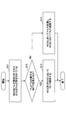
- FIG. 2 is a diagram for explaining an operation example (1) of the wireless communication system in the embodiment of the present invention.
- the timing advance value of the LTE PCell by the MN 10A is TA 1
- the timing advance value of the NR PSCell by the SN 10B is TA 2 .
- the PCell of LTE and the PSCell of NR are arranged in the intra band.
- the user equipment 20 uses the timing advance value set in each cell group, and when the deviation of the UL transmission timing between the cell groups exceeds MTTD, The timing advance value of MCG is used.
- FIG. 3 is a flowchart for explaining an operation example (1) of the wireless communication system according to the embodiment of the present invention.
- FIG. 3 an operation example of the user apparatus 20 in the communication state shown in FIG. 2 will be described.
- step S11 regarding the timing advance value of the user equipment 20, TA 1 is set in MCG and TA 2 is set in SCG. Then, it is determined whether the difference between TA 1 and TA 2 exceeds MTTD. If it exceeds MTTD (YES in S12), the process proceeds to step S13, and if it does not exceed MTTD (NO in S12), the process proceeds to step S14.
- step S13 the user equipment 20 transmits the timing advance value with TA 1 in the MCG and SCG.
- step S14 the user equipment 20 transmits the timing advance value with TA 1 in the MCG and the timing advance value with TA 2 in the SCG.
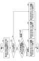
- FIG. 4 is a diagram for explaining an operation example (2) of the wireless communication system in the embodiment of the present invention.
- the timing advance value of the PCell belonging to the LTE pTAG (primary Timing Advance Group) of the MN 10A is TA 1
- the timing advance value of the SCell 2 belonging to the LTE sTAG (secondary Timing Advance Group) of the MN 10A is TA.
- the timing advance value of PSCell of NR by SN10B is to TA 3.
- the PCell of LTE, the SCell of LTE, and the PSCell of NR are all arranged in the intra band. Note that PCell may be called a master cell of a master cell group, PSCell may be called a master cell of a secondary cell group, and SCell may be called a secondary cell.
- FIG. 5 is a flowchart for explaining an operation example (2) of the wireless communication system according to the embodiment of the present invention.
- an operation example of the user device 20 in the communication state shown in FIG. 4 will be described.
- step S21 regarding the timing advance value of the user equipment 20, TA 1 is set to pTAG of MCG, TA 2 is set to sTAG of MCG, and TA 3 is set to SCG. Then, it is determined whether the difference between TA 1 and TA 3 exceeds MTTD. If it exceeds MTTD (YES in S22), the process proceeds to step S23, and if it does not exceed MTTD (NO in S22), the process proceeds to step S26.
- step S23 it is determined whether the PSCell frequency is closer to the MCG PCell frequency or the MCG SCell frequency.
- the process proceeds to step S24.
- the frequency is close to the SCell of SCG, the process proceeds to step S25.
- the example shown in FIG. 4 shows a case where the frequency of PSCell is close to the frequency of SCell of SCG.
- step S24 the user equipment 20 transmits the timing advance value by TA 1 in the PCell of MCG, TA 2 in the SCell belonging to the sTAG of MCG, and TA 1 in the SCG.
- step S25 the user device 20, a timing advance value, transmitted by TA 1 in PCell of MCG, transmitted by TA 2 in SCell belonging to MCG of sTAG, transmitted by TA 2 in SCG.
- step S26 the user equipment 20 transmits the timing advance value by TA 1 in the PCell of MCG, TA 2 in the SCell belonging to the sTAG of MCG, and TA 3 in the SCG.
- Step S21 to S23 shown in FIG. 5 are the same.
- the user equipment 20 transmits the timing advance value by TA 1 in the SCell belonging to the sTAG of the SCG.
- the user equipment 20 transmits the timing advance value by TA 2 in the SCell belonging to the sTAG of the SCG.
- the user apparatus 20 transmits the timing advance value by TA 4 in the SCell belonging to the sTAG of the SCG.
- the user equipment 20 can set the timing advance at the time of intra-band synchronous dual connectivity based on the timing advance value of each cell group. Moreover, the user apparatus 20 can set the timing advance at the time of intra-band synchronous dual connectivity based on the frequency allocation of each cell group.
- the user apparatus can appropriately control the communication to which the dual connectivity is applied according to the transmission timing difference between the cell groups.
- the base station device 10 and the user device 20 include a function for implementing the above-described embodiment. However, each of the base station device 10 and the user device 20 may have only some of the functions in the embodiment.
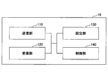
- FIG. 6 is a diagram illustrating an example of a functional configuration of the base station device 10.
- the base station device 10 includes a transmission unit 110, a reception unit 120, a setting unit 130, and a control unit 140.
- the functional configuration shown in FIG. 6 is merely an example. As long as the operation according to the embodiment of the present invention can be executed, the function categories and the names of the function units may be any names.
- the transmitting unit 110 includes a function of generating a signal to be transmitted to the user device 20 side and wirelessly transmitting the signal.
- the receiving unit 120 includes a function of receiving various signals transmitted from the user device 20 and acquiring, for example, information of a higher layer from the received signals. Further, the transmission unit 110 has a function of transmitting NR-PSS, NR-SSS, NR-PBCH, DL / UL control signal, DL reference signal, etc. to the user apparatus 20.
- the setting unit 130 stores preset setting information and various setting information to be transmitted to the user device 20, in the storage device, and reads from the storage device as necessary.
- the content of the setting information is, for example, information related to the setting of the communication to which the dual connectivity is applied.
- control unit 140 performs a process related to the setting for the user device 20 to perform communication to which dual connectivity is applied. Further, the control unit 140 transmits the scheduling of the communication to which the dual connectivity is applied to the user device 20 via the transmission unit 110.
- the functional unit related to signal transmission in the control unit 140 may be included in the transmission unit 110, and the functional unit related to signal reception in the control unit 140 may be included in the reception unit 120.
- FIG. 7 is a diagram illustrating an example of a functional configuration of the user device 20.
- the user device 20 includes a transmission unit 210, a reception unit 220, a setting unit 230, and a control unit 240.
- the functional configuration shown in FIG. 7 is merely an example. As long as the operation according to the embodiment of the present invention can be executed, the function categories and the names of the function units may be any names.
- the transmitter 210 generates a transmission signal from the transmission data and wirelessly transmits the transmission signal.
- the reception unit 220 wirelessly receives various signals and acquires higher-layer signal from the received physical-layer signal.
- the receiving unit 220 also has a function of receiving the NR-PSS, NR-SSS, NR-PBCH, DL / UL / SL control signal, reference signal, or the like transmitted from the base station apparatus 10.
- the setting unit 230 stores various setting information received from the base station device 10 or the user device 20 by the receiving unit 220 in a storage device, and reads from the storage device as necessary.
- the setting unit 230 also stores preset setting information.
- the content of the setting information is, for example, information related to the setting of the communication to which the dual connectivity is applied.
- the control unit 240 controls the communication to which the dual connectivity is applied, as described in the embodiment. In addition, the control unit 240 executes control related to the timing advance value of the communication to which the dual connectivity is applied.
- the functional unit related to signal transmission in the control unit 240 may be included in the transmission unit 210, and the functional unit related to signal reception in the control unit 240 may be included in the reception unit 220.
- each functional block may be realized by using one device physically or logically coupled, or directly or indirectly (for example, two or more devices physically or logically separated). , Wired, wireless, etc.) and may be implemented using these multiple devices.
- the functional blocks may be realized by combining the one device or the plurality of devices with software.
- Functions include judgment, decision, judgment, calculation, calculation, processing, derivation, investigation, search, confirmation, reception, transmission, output, access, resolution, selection, selection, establishment, comparison, assumption, expectation, observation, Broadcasting, notifying, communicating, forwarding, configuring, reconfiguring, allocating, mapping, assigning, etc., but not limited to these.
- a functional block (component) that functions for transmission is called a transmitting unit or a transmitter.
- the implementation method is not particularly limited.
- the base station device 10, the user device 20, and the like according to the embodiment of the present disclosure may function as a computer that performs the process of the wireless communication method of the present disclosure.
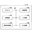
- FIG. 8 is a diagram illustrating an example of a hardware configuration of the base station device 10 and the user device 20 according to the embodiment of the present disclosure.
- the base station device 10 and the user device 20 described above are physically configured as a computer device including a processor 1001, a storage device 1002, an auxiliary storage device 1003, a communication device 1004, an input device 1005, an output device 1006, a bus 1007, and the like. May be done.
- the word “device” can be read as a circuit, device, unit, or the like.
- the hardware configurations of the base station device 10 and the user device 20 may be configured to include one or a plurality of each device illustrated in the figure, or may be configured not to include some devices.
- Each function in the base station device 10 and the user device 20 causes a predetermined software (program) to be loaded onto hardware such as the processor 1001, the storage device 1002, etc., so that the processor 1001 performs calculation and communication by the communication device 1004. It is realized by controlling or at least one of reading and writing of data in the storage device 1002 and the auxiliary storage device 1003.
- the processor 1001 operates an operating system to control the entire computer, for example.
- the processor 1001 may be configured by a central processing unit (CPU) including an interface with peripheral devices, a control device, an arithmetic device, a register, and the like.
- CPU central processing unit
- the control unit 140, the control unit 240, and the like described above may be realized by the processor 1001.
- the processor 1001 also reads a program (program code), software module, data, or the like from at least one of the auxiliary storage device 1003 and the communication device 1004 to the storage device 1002, and executes various processes according to these.
- a program that causes a computer to execute at least a part of the operations described in the above-described embodiments is used.
- the control unit 140 of the base station device 10 illustrated in FIG. 6 may be realized by a control program stored in the storage device 1002 and operated by the processor 1001.
- the control unit 240 of the user device 20 illustrated in FIG. 7 may be realized by a control program stored in the storage device 1002 and operated by the processor 1001.
- the processor 1001 may be implemented by one or more chips.
- the program may be transmitted from the network via an electric communication line.
- the storage device 1002 is a computer-readable recording medium, and includes, for example, at least one of ROM (Read Only Memory), EPROM (Erasable Programmable ROM), EEPROM (Electrically Erasable Programmable ROM), RAM (Random Access Memory), and the like. It may be configured.
- the storage device 1002 may be called a register, a cache, a main memory (main storage device), or the like.
- the storage device 1002 can store an executable program (program code), a software module, or the like for implementing the communication method according to the embodiment of the present disclosure.
- the auxiliary storage device 1003 is a computer-readable recording medium, and is, for example, an optical disk such as a CD-ROM (Compact Disc ROM), a hard disk drive, a flexible disk, a magneto-optical disk (for example, compact disk, digital versatile disk, Blu -Ray disk), smart card, flash memory (eg card, stick, key drive), floppy disk, magnetic strip, etc.
- the above-described storage medium may be, for example, a database including at least one of the storage device 1002 and the auxiliary storage device 1003, a server, or another appropriate medium.
- the communication device 1004 is hardware (transmission / reception device) for performing communication between computers via at least one of a wired network and a wireless network, and is also called, for example, a network device, a network controller, a network card, a communication module, or the like.
- the communication device 1004 includes, for example, a high frequency switch, a duplexer, a filter, a frequency synthesizer, and the like in order to realize at least one of frequency division duplex (FDD: Frequency Division Duplex) and time division duplex (TDD: Time Division Duplex). May be composed of
- FDD Frequency Division Duplex
- TDD Time Division Duplex
- the transmitter / receiver may be implemented by physically or logically separating the transmitter and the receiver.
- the input device 1005 is an input device (for example, a keyboard, a mouse, a microphone, a switch, a button, a sensor, etc.) that receives an input from the outside.
- the output device 1006 is an output device (for example, a display, a speaker, an LED lamp, etc.) that outputs to the outside.
- the input device 1005 and the output device 1006 may be integrated (for example, a touch panel).
- each device such as the processor 1001 and the storage device 1002 is connected by a bus 1007 for communicating information.
- the bus 1007 may be configured by using a single bus, or may be configured by using a different bus for each device.
- the base station device 10 and the user device 20 include a microprocessor, a digital signal processor (DSP: Digital Signal Processor), an ASIC (Application Specific Integrated Circuit), a PLD (Programmable Logic Device), an FPGA (Field Programmable Gate Array), and the like. It may be configured to include hardware, and the hardware may implement part or all of each functional block. For example, the processor 1001 may be implemented using at least one of these hardware.
- DSP Digital Signal Processor
- ASIC Application Specific Integrated Circuit
- PLD Programmable Logic Device
- FPGA Field Programmable Gate Array
- the first timing advance value of the first cell group in dual connectivity and the second timing advance value of the second cell group in dual connectivity are used.
- a control unit that determines the transmission timing in the first cell group and the transmission timing in the second cell group based on the difference between the first and second cell groups; and the first based on the determined transmission timing in the first cell group.
- a transmitting unit that performs transmission in the second cell group based on the determined transmission timing in the second cell group.
- the user equipment 20 can set the timing advance at the time of intra-band synchronous dual connectivity based on the timing advance value of each cell group. That is, the user apparatus can appropriately control the communication to which the dual connectivity is applied according to the transmission timing difference between the cell groups.
- the control unit sets the transmission timing in the second cell group to the first timing advance value. You may decide. With this configuration, the user equipment 20 can set the timing advance at the time of intra-band synchronization dual connectivity based on the timing advance value of each cell group.
- a first timing advance value is set in the primary timing alignment group of the first cell group
- a third timing advance value is set in the secondary timing alignment group of the first cell group
- the third timing advance value is set in the secondary timing alignment group of the first cell group.
- a second timing advance value is set in the primary timing alignment group of the second cell group, and a fourth timing advance value is set in the secondary timing alignment group of the second cell group, and
- the control unit sets the transmission timing in the secondary timing alignment group of the second cell group to the first cell.
- the frequencies of the master cells belonging to the primary timing alignment group of the group and the frequencies of the secondary cells belonging to the secondary timing alignment group of the first cell group timing alignment of frequencies closer to the frequencies of the master cells of the second cell group
- the timing advance value set in the group may be determined. With this configuration, the user equipment 20 can set the timing advance at the time of intra-band synchronous dual connectivity based on the frequency arrangement of each cell group.
- a receiving unit that executes the above and executes reception in the second cell group based on the determined reception timing in the second cell group.
- the user equipment 20 can set the timing advance at the time of intra-band synchronous dual connectivity based on the timing advance value of each cell group. That is, the user apparatus can appropriately control the communication to which the dual connectivity is applied according to the transmission timing difference between the cell groups.
- the operation of the plurality of functional units may be physically performed by one component, or the operation of one functional unit may be physically performed by the plurality of components.
- the order of processing may be changed as long as there is no contradiction.
- the base station apparatus 10 and the user apparatus 20 are described using functional block diagrams for convenience of processing description, such an apparatus may be realized by hardware, software, or a combination thereof.
- the software operated by the processor included in the base station device 10 according to the embodiment of the present invention and the software operated by the processor included in the user device 20 according to the embodiment of the present invention are respectively a random access memory (RAM), a flash memory, and a read memory. It may be stored in a dedicated memory (ROM), EPROM, EEPROM, register, hard disk (HDD), removable disk, CD-ROM, database, server, or any other suitable storage medium.
- the notification of information is not limited to the mode / embodiment described in the present disclosure, and may be performed using another method.
- information is notified by physical layer signaling (for example, DCI (Downlink Control Information), UCI (Uplink Control Information)), upper layer signaling (for example, RRC (Radio Resource Control) signaling, MAC (Medium Access Control) signaling, It may be carried out by broadcast information (MIB (Master Information Block), SIB (System Information Block)), other signals, or a combination thereof, and RRC signaling may be called an RRC message, for example, RRC message. It may be a connection setup (RRC Connection Setup) message, an RRC connection reconfiguration message, or the like.
- LTE Long Term Evolution
- LTE-A Long Term Evolution-Advanced
- SUPER 3G IMT-Advanced
- 4G 4th generation mobile communication system
- 5G 5th generation mobile communication system
- FRA Full Radio Access
- NR new Radio
- W-CDMA registered trademark
- GSM registered trademark
- CDMA2000 Code Division Multiple Access 2000
- UMB Universal Mobile Broadband
- IEEE 802.11 Wi-Fi (registered trademark)
- IEEE 802.16 WiMAX (registered trademark)
- IEEE 802.20 UWB (Ultra-WideBand
- Bluetooth registered trademark
- other systems using appropriate systems, and extensions based on these It may be applied to at least one of the next-generation systems.
- a plurality of systems may be combined and applied (for example, a combination of at least one of LTE and LTE-A and 5G).
- the specific operation that is performed by the base station device 10 in this specification may be performed by its upper node in some cases.
- various operations performed for communication with the user device 20 are other than the base station device 10 and the base station device 10.
- it may be performed by at least one of the network nodes of (eg, but not limited to, MME or S-GW, etc.).
- the other network node may be a combination of a plurality of other network nodes (for example, MME and S-GW). Good.
- Information, signals, etc. described in the present disclosure may be output from the upper layer (or lower layer) to the lower layer (or upper layer). Input / output may be performed via a plurality of network nodes.
- Information that has been input and output may be stored in a specific location (for example, memory), or may be managed using a management table. Information that is input / output may be overwritten, updated, or added. The output information and the like may be deleted. The input information and the like may be transmitted to another device.
- the determination in the present disclosure may be performed based on a value (0 or 1) represented by 1 bit, may be performed based on a Boolean value (Boolean: true or false), or may be performed by comparing numerical values (for example, , Comparison with a predetermined value).
- software, instructions, information, etc. may be sent and received via a transmission medium.
- the software uses a wired technology (coaxial cable, optical fiber cable, twisted pair, digital subscriber line (DSL: Digital Subscriber Line), etc.) and / or wireless technology (infrared, microwave, etc.) websites, When sent from a server, or other remote source, at least one of these wired and wireless technologies is included within the definition of transmission medium.
- wired technology coaxial cable, optical fiber cable, twisted pair, digital subscriber line (DSL: Digital Subscriber Line), etc.
- wireless technology infrared, microwave, etc.
- Information, signals, etc. described in this disclosure may be represented using any of a variety of different technologies.
- data, instructions, commands, information, signals, bits, symbols, chips, etc. that may be referred to throughout the above description include voltage, current, electromagnetic waves, magnetic fields or magnetic particles, optical fields or photons, or any of these. May be represented by a combination of
- At least one of the channel and the symbol may be a signal (signaling).
- the signal may also be a message.
- a component carrier CC may be called a carrier frequency, a cell, a frequency carrier, or the like.
- system and “network” used in this disclosure are used interchangeably.
- the information, parameters, etc. described in the present disclosure may be represented by using an absolute value, may be represented by using a relative value from a predetermined value, or by using other corresponding information. May be represented.
- the radio resources may be those indicated by the index.
- base station Base Station
- radio base station base station
- base station device fixed station
- NodeB NodeB
- eNodeB eNodeB
- GNB gNodeB
- access point “ transmission point ”,“ reception point ”,“ transmission / reception point ”,“ cell ”,“ sector ”
- Terms such as “cell group”, “carrier”, “component carrier” may be used interchangeably.
- a base station may be referred to by terms such as macro cell, small cell, femto cell, pico cell, and the like.
- a base station can accommodate one or more (eg, three) cells.
- a base station accommodates multiple cells, the entire coverage area of the base station can be divided into multiple smaller areas, each smaller area being defined by a base station subsystem (eg, indoor small base station (RRH: Communication services can also be provided by Remote Radio Head) .
- RRH indoor small base station
- the term "cell” or “sector” refers to a part or the whole of the coverage area of at least one of the base station and the base station subsystem that perform communication services in this coverage. Refers to.
- MS Mobile Station
- UE User Equipment
- Mobile stations are defined by those skilled in the art as subscriber stations, mobile units, subscriber units, wireless units, remote units, mobile devices, wireless devices, wireless communication devices, remote devices, mobile subscriber stations, access terminals, mobile terminals, wireless. It may also be referred to as a terminal, remote terminal, handset, user agent, mobile client, client, or some other suitable term.
- At least one of the base station and the mobile station may be called a transmission device, a reception device, a communication device, or the like.
- the base station and the mobile station may be a device mounted on the mobile body, the mobile body itself, or the like.
- the moving body may be a vehicle (eg, car, airplane, etc.), an unmanned moving body (eg, drone, self-driving car, etc.), or a robot (manned or unmanned).
- At least one of the base station and the mobile station also includes a device that does not necessarily move during a communication operation.
- at least one of the base station and the mobile station may be an IoT (Internet of Things) device such as a sensor.
- IoT Internet of Things
- the base station in the present disclosure may be replaced by the user terminal.
- the communication between the base station and the user terminal is replaced with communication between a plurality of user devices 20 (eg, may be called D2D (Device-to-Device), V2X (Vehicle-to-Everything), etc.)
- a plurality of user devices 20 eg, may be called D2D (Device-to-Device), V2X (Vehicle-to-Everything), etc.
- the user apparatus 20 may have the function of the above-described base station apparatus 10.
- the wording such as “up” and “down” may be replaced with the wording corresponding to the communication between terminals (for example, “side”).
- the uplink channel and the downlink channel may be replaced with the side channel.
- the user terminal in the present disclosure may be replaced by the base station.
- the base station may have the function of the above-described user terminal.
- determining and “determining” as used in this disclosure may encompass a wide variety of actions.
- “Judgment” and “decision” are, for example, judgment, calculation, computing, processing, processing, deriving, investigating, and looking up, search, inquiry. (Eg, searching in a table, a database, or another data structure), considering ascertaining as “judging” or “deciding” may be included.
- “decision” and “decision” include receiving (eg, receiving information), transmitting (eg, transmitting information), input (input), output (output), access (accessing) (for example, accessing data in a memory) may be regarded as “judging” and “deciding”.
- judgment and “decision” are considered to be “judgment” and “decision” when things such as resolving, selecting, choosing, establishing, establishing, and comparing are done. May be included. That is, the “judgment” and “decision” may include considering some action as “judged” and “decided”. In addition, “determination (decision)” may be read as “assuming,” “expecting,” “considering,” and the like.
- connection means any direct or indirect connection or coupling between two or more elements, and It can include the presence of one or more intermediate elements between two elements that are “connected” or “coupled”.
- the connections or connections between the elements may be physical, logical, or a combination thereof.
- connection may be read as “access”.
- two elements are in the radio frequency domain, with at least one of one or more wires, cables and printed electrical connections, and as some non-limiting and non-exhaustive examples. , Can be considered to be “connected” or “coupled” to each other, such as with electromagnetic energy having wavelengths in the microwave and light (both visible and invisible) regions.
- the reference signal may be abbreviated as RS (Reference Signal), or may be referred to as a pilot (Pilot) depending on the applied standard.
- RS Reference Signal
- Pilot pilot
- the phrase “based on” does not mean “based only on,” unless expressly specified otherwise. In other words, the phrase “based on” means both "based only on” and “based at least on.”
- references to elements using designations such as “first”, “second”, etc. as used in this disclosure does not generally limit the amount or order of those elements. These designations may be used in this disclosure as a convenient way to distinguish between two or more elements. Thus, references to the first and second elements do not mean that only two elements may be employed, or that the first element must precede the second element in any way.
- a radio frame may be composed of one or more frames in the time domain. Each frame or frames in the time domain may be referred to as a subframe. A subframe may also be composed of one or more slots in the time domain. The subframe may have a fixed time length (eg, 1 ms) that does not depend on numerology.
- Numerology may be a communication parameter applied to at least one of transmission and reception of a signal or channel.
- Numerology includes, for example, subcarrier spacing (SCS: SubCarrier Spacing), bandwidth, symbol length, cyclic prefix length, transmission time interval (TTI: Transmission Time Interval), number of symbols per TTI, radio frame configuration, transceiver At least one of a specific filtering process performed in the frequency domain and a specific windowing process performed by the transceiver in the time domain may be shown.
- a slot may be composed of one or more symbols (OFDM (Orthogonal Frequency Division Multiplexing) symbol, SC-FDMA (Single Carrier Frequency Division Multiple Access) symbol, etc.) in the time domain.
- a slot may be a time unit based on numerology.
- a slot may include multiple minislots. Each minislot may be composed of one or more symbols in the time domain. The minislot may also be called a subslot. Minislots may be composed of fewer symbols than slots.
- PDSCH (or PUSCH) transmitted in a time unit larger than a minislot may be referred to as PDSCH (or PUSCH) mapping type A.
- PDSCH (or PUSCH) transmitted using a minislot may be referred to as PDSCH (or PUSCH) mapping type B.
- Radio frame, subframe, slot, minislot, and symbol all represent the time unit for transmitting signals. Radio frames, subframes, slots, minislots, and symbols may have different names corresponding to them.
- one subframe may be called a transmission time interval (TTI)
- TTI transmission time interval
- TTI transmission time interval
- a plurality of consecutive subframes may be called a TTI
- one slot or one minislot is called a TTI.
- You may. That is, at least one of the subframe and the TTI may be a subframe (1 ms) in existing LTE, a period shorter than 1 ms (eg, 1-13 symbols), or a period longer than 1 ms. May be The unit representing the TTI may be called a slot, a minislot, etc. instead of a subframe.
- TTI means, for example, the minimum time unit of scheduling in wireless communication.
- the base station performs scheduling for allocating radio resources (frequency bandwidth that can be used in each user device 20, transmission power, etc.) to each user device 20 in units of TTI.
- the definition of TTI is not limited to this.
- the TTI may be a transmission time unit of a channel-encoded data packet (transport block), code block, codeword, or the like, or may be a processing unit of scheduling, link adaptation, or the like.
- the time interval for example, the number of symbols
- the transport block, code block, codeword, etc. may be shorter than the TTI.
- one slot or one minislot is called a TTI
- one or more TTIs may be the minimum time unit for scheduling.
- the number of slots (minislot number) that constitutes the minimum time unit of the scheduling may be controlled.
- a TTI having a time length of 1 ms may be called a normal TTI (TTI in LTE Rel. 8-12), a normal TTI, a long TTI, a normal subframe, a normal subframe, a long subframe, a slot, or the like.
- the TTI shorter than the normal TTI may be called a shortened TTI, a short TTI, a partial TTI (partial or fractional TTI), a shortened subframe, a short subframe, a minislot, a subslot, a slot, and the like.
- a long TTI (eg, normal TTI, subframe, etc.) may be read as a TTI having a time length of more than 1 ms, and a short TTI (eg, shortened TTI, etc.) is less than the TTI length of the long TTI and 1 ms. It may be read as a TTI having the above TTI length.
- a resource block is a resource allocation unit in the time domain and the frequency domain, and may include one or more continuous subcarriers in the frequency domain.
- the number of subcarriers included in the RB may be the same regardless of the numerology, and may be 12, for example.
- the number of subcarriers included in the RB may be determined based on numerology.
- the time domain of the RB may include one or more symbols, and may be one slot, one minislot, one subframe, or one TTI in length.
- Each 1 TTI, 1 subframe, etc. may be configured with one or a plurality of resource blocks.
- One or more RBs are a physical resource block (PRB: Physical RB), subcarrier group (SCG: Sub-Carrier Group), resource element group (REG: Resource Element Group), PRB pair, RB pair, etc. May be called.
- PRB Physical resource block
- SCG Sub-Carrier Group
- REG Resource Element Group
- PRB pair RB pair, etc. May be called.
- a resource block may be composed of one or more resource elements (RE: Resource Element).
- RE Resource Element
- one RE may be a radio resource area of one subcarrier and one symbol.
- a bandwidth part (may be called a partial bandwidth) may represent a subset of consecutive common RBs (common resource blocks) for a certain numerology in a certain carrier.
- the common RB may be specified by the index of the RB based on the common reference point of the carrier.
- PRBs may be defined in a BWP and numbered within that BWP.
- BWP may include BWP for UL (UL BWP) and BWP for DL (DL BWP).
- BWP for UL
- DL BWP BWP for DL
- One or more BWPs may be set in one carrier for the UE.
- At least one of the configured BWPs may be active, and the UE does not have to assume that it will send and receive predetermined signals / channels outside the active BWP.
- BWP bitmap
- the above-described structure of the radio frame, subframe, slot, minislot, symbol, etc. is merely an example.
- the number of subframes included in a radio frame, the number of slots per subframe or radio frame, the number of minislots included in a slot, the number of symbols and RBs included in a slot or minislot, and included in RBs The number of subcarriers, the number of symbols in the TTI, the symbol length, the cyclic prefix (CP: Cyclic Prefix) length, and the like can be variously changed.
- the term “A and B are different” may mean “A and B are different from each other”.
- the term may mean that “A and B are different from C”.
- the terms “remove”, “coupled” and the like may be construed as “different” as well.
- the notification of the predetermined information (for example, the notification of “being X”) is not limited to the explicit notification, but is performed implicitly (for example, the notification of the predetermined information is not performed). Good.
- the master cell group is an example of the first cell group.
- the secondary cell group is an example of the second cell group.
- base station device 110 transmission unit 120 reception unit 130 setting unit 140 control unit 20 user device 210 transmission unit 220 reception unit 230 setting unit 240 control unit 1001 processor 1002 storage device 1003 auxiliary storage device 1004 communication device 1005 input device 1006 output device
Abstract
Description
次に、これまでに説明した処理及び動作を実行する基地局装置10及びユーザ装置20の機能構成例を説明する。基地局装置10及びユーザ装置20は上述した実施例を実施する機能を含む。ただし、基地局装置10及びユーザ装置20はそれぞれ、実施例の中の一部の機能のみを備えることとしてもよい。 (Device configuration)
Next, a functional configuration example of the
図6は、基地局装置10の機能構成の一例を示す図である。図6に示されるように、基地局装置10は、送信部110と、受信部120と、設定部130と、制御部140とを有する。図6に示される機能構成は一例に過ぎない。本発明の実施の形態に係る動作を実行できるのであれば、機能区分及び機能部の名称はどのようなものでもよい。 <
FIG. 6 is a diagram illustrating an example of a functional configuration of the
図7は、ユーザ装置20の機能構成の一例を示す図である。図7に示されるように、ユーザ装置20は、送信部210と、受信部220と、設定部230と、制御部240とを有する。図7に示される機能構成は一例に過ぎない。本発明の実施の形態に係る動作を実行できるのであれば、機能区分及び機能部の名称はどのようなものでもよい。 <
FIG. 7 is a diagram illustrating an example of a functional configuration of the
上記実施形態の説明に用いたブロック図(図6及び図7)は、機能単位のブロックを示している。これらの機能ブロック(構成部)は、ハードウェア及びソフトウェアの少なくとも一方の任意の組み合わせによって実現される。また、各機能ブロックの実現方法は特に限定されない。すなわち、各機能ブロックは、物理的又は論理的に結合した1つの装置を用いて実現されてもよいし、物理的又は論理的に分離した2つ以上の装置を直接的又は間接的に(例えば、有線、無線などを用いて)接続し、これら複数の装置を用いて実現されてもよい。機能ブロックは、上記1つの装置又は上記複数の装置にソフトウェアを組み合わせて実現されてもよい。 (Hardware configuration)
The block diagrams (FIGS. 6 and 7) used in the description of the above embodiment show functional unit blocks. These functional blocks (components) are realized by an arbitrary combination of at least one of hardware and software. The method of realizing each functional block is not particularly limited. That is, each functional block may be realized by using one device physically or logically coupled, or directly or indirectly (for example, two or more devices physically or logically separated). , Wired, wireless, etc.) and may be implemented using these multiple devices. The functional blocks may be realized by combining the one device or the plurality of devices with software.
以上、説明したように、本発明の実施の形態によれば、デュアルコネクティビティにおける第1のセルグループの第1のタイミングアドバンス値と、デュアルコネクティビティにおける第2のセルグループの第2のタイミングアドバンス値との差に基づいて、前記第1のセルグループにおける送信タイミング及び前記第2のセルグループにおける送信タイミングを決定する制御部と、前記決定された第1のセルグループにおける送信タイミングに基づいて前記第1のセルグループにおいて送信を実行し、前記決定された第2のセルグループにおける送信タイミングに基づいて前記第2のセルグループにおいて送信を実行する送信部とを有するユーザ装置が提供される。 (Summary of Embodiments)
As described above, according to the embodiment of the present invention, the first timing advance value of the first cell group in dual connectivity and the second timing advance value of the second cell group in dual connectivity are used. A control unit that determines the transmission timing in the first cell group and the transmission timing in the second cell group based on the difference between the first and second cell groups; and the first based on the determined transmission timing in the first cell group. And a transmitting unit that performs transmission in the second cell group based on the determined transmission timing in the second cell group.
以上、本発明の実施の形態を説明してきたが、開示される発明はそのような実施形態に限定されず、当業者は様々な変形例、修正例、代替例、置換例等を理解するであろう。発明の理解を促すため具体的な数値例を用いて説明がなされたが、特に断りのない限り、それらの数値は単なる一例に過ぎず適切な如何なる値が使用されてもよい。上記の説明における項目の区分けは本発明に本質的ではなく、2以上の項目に記載された事項が必要に応じて組み合わせて使用されてよいし、ある項目に記載された事項が、別の項目に記載された事項に(矛盾しない限り)適用されてよい。機能ブロック図における機能部又は処理部の境界は必ずしも物理的な部品の境界に対応するとは限らない。複数の機能部の動作が物理的には1つの部品で行われてもよいし、あるいは1つの機能部の動作が物理的には複数の部品により行われてもよい。実施の形態で述べた処理手順については、矛盾の無い限り処理の順序を入れ替えてもよい。処理説明の便宜上、基地局装置10及びユーザ装置20は機能的なブロック図を用いて説明されたが、そのような装置はハードウェアで、ソフトウェアで又はそれらの組み合わせで実現されてもよい。本発明の実施の形態に従って基地局装置10が有するプロセッサにより動作するソフトウェア及び本発明の実施の形態に従ってユーザ装置20が有するプロセッサにより動作するソフトウェアはそれぞれ、ランダムアクセスメモリ(RAM)、フラッシュメモリ、読み取り専用メモリ(ROM)、EPROM、EEPROM、レジスタ、ハードディスク(HDD)、リムーバブルディスク、CD-ROM、データベース、サーバその他の適切な如何なる記憶媒体に保存されてもよい。 (Supplement to the embodiment)
Although the embodiment of the present invention has been described above, the disclosed invention is not limited to such an embodiment, and those skilled in the art can understand various modifications, modifications, alternatives, and substitutions. Let's see Although specific numerical values are used for the purpose of facilitating the understanding of the invention, unless otherwise specified, those numerical values are merely examples and any appropriate values may be used. The division of items in the above description is not essential to the present invention, and items described in two or more items may be used in combination as necessary, and items described in one item may be different items. It may apply to the matters described in (as long as there is no conflict). The boundaries of the functional units or processing units in the functional block diagram do not always correspond to the boundaries of physical parts. The operation of the plurality of functional units may be physically performed by one component, or the operation of one functional unit may be physically performed by the plurality of components. Regarding the processing procedures described in the embodiments, the order of processing may be changed as long as there is no contradiction. Although the
110 送信部
120 受信部
130 設定部
140 制御部
20 ユーザ装置
210 送信部
220 受信部
230 設定部
240 制御部
1001 プロセッサ
1002 記憶装置
1003 補助記憶装置
1004 通信装置
1005 入力装置
1006 出力装置 10
Claims (5)
- デュアルコネクティビティにおける第1のセルグループの第1のタイミングアドバンス値と、デュアルコネクティビティにおける第2のセルグループの第2のタイミングアドバンス値との差に基づいて、前記第1のセルグループにおける送信タイミング及び前記第2のセルグループにおける送信タイミングを決定する制御部と、
前記決定された第1のセルグループにおける送信タイミングに基づいて前記第1のセルグループにおいて送信を実行し、前記決定された第2のセルグループにおける送信タイミングに基づいて前記第2のセルグループにおいて送信を実行する送信部とを有するユーザ装置。 Based on the difference between the first timing advance value of the first cell group in dual connectivity and the second timing advance value of the second cell group in dual connectivity, the transmission timing in the first cell group and the A control unit that determines the transmission timing in the second cell group;
Transmission is performed in the first cell group based on the determined transmission timing in the first cell group, and transmission is performed in the second cell group based on the determined transmission timing in the second cell group. A user device having: - 前記制御部は、前記第1のタイミングアドバンス値と前記第2のタイミングアドバンス値との差が所定の値を超える場合、前記第2のセルグループにおける送信タイミングを、前記第1のタイミングアドバンス値に決定する請求項1記載のユーザ装置。 When the difference between the first timing advance value and the second timing advance value exceeds a predetermined value, the control unit sets the transmission timing in the second cell group to the first timing advance value. The user equipment according to claim 1, which determines.
- 前記第1のセルグループのプライマリタイミングアライメントグループに第1のタイミングアドバンス値が設定され、かつ、前記第1のセルグループのセカンダリタイミングアライメントグループに第3のタイミングアドバンス値が設定され、かつ、前記第1のタイミングアドバンス値と前記第2のタイミングアドバンス値との差が所定の値を超える場合、
前記制御部は、前記第2のセルグループにおける送信タイミングを、前記第1のセルグループのプライマリタイミングアライメントグループに属するマスタセルの周波数と、前記第1のセルグループのセカンダリタイミングアライメントグループに属するセカンダリセルの周波数とのうち、前記第2のセルグループのマスタセルの周波数により近い周波数のタイミングアライメントグループに設定されるタイミングアドバンス値に決定する請求項1記載のユーザ装置。 A first timing advance value is set in the primary timing alignment group of the first cell group, a third timing advance value is set in the secondary timing alignment group of the first cell group, and the third timing advance value is set in the secondary timing alignment group of the first cell group. When the difference between the timing advance value of 1 and the second timing advance value exceeds a predetermined value,
The control unit controls the transmission timing in the second cell group, the frequency of the master cell belonging to the primary timing alignment group of the first cell group, and the secondary cell belonging to the secondary timing alignment group of the first cell group. The user equipment according to claim 1, wherein the timing advance value set to a timing alignment group having a frequency closer to the frequency of the master cell of the second cell group among the frequencies is determined. - 前記第2のセルグループのプライマリタイミングアライメントグループに第2のタイミングアドバンス値が設定され、かつ、前記第2のセルグループのセカンダリタイミングアライメントグループに第4のタイミングアドバンス値が設定され、かつ、前記第1のタイミングアドバンス値と前記第2のタイミングアドバンス値との差が所定の値を超える場合、
前記制御部は、前記第2のセルグループのセカンダリタイミングアライメントグループにおける送信タイミングを、前記第1のセルグループのプライマリタイミングアライメントグループに属するマスタセルの周波数と、前記第1のセルグループのセカンダリタイミングアライメントグループに属するセカンダリセルの周波数とのうち、前記第2のセルグループのマスタセルの周波数により近い周波数のタイミングアライメントグループに設定されるタイミングアドバンス値に決定する請求項3記載のユーザ装置。 A second timing advance value is set in the primary timing alignment group of the second cell group, and a fourth timing advance value is set in the secondary timing alignment group of the second cell group, and When the difference between the timing advance value of 1 and the second timing advance value exceeds a predetermined value,
The control unit controls the transmission timing in the secondary timing alignment group of the second cell group, the frequency of the master cell belonging to the primary timing alignment group of the first cell group, and the secondary timing alignment group of the first cell group. 4. The user equipment according to claim 3, wherein the timing advance value is set to a timing alignment group having a frequency closer to the frequency of the master cell of the second cell group among the frequencies of the secondary cells belonging to. - デュアルコネクティビティにおける第1のセルグループの第1のタイミングアドバンス値と、デュアルコネクティビティにおける第2のセルグループの第2のタイミングアドバンス値との差に基づいて、前記第1のセルグループにおける受信タイミング及び前記第2のセルグループにおける受信タイミングを決定する制御部と、
前記決定された第1のセルグループにおける受信タイミングに基づいて前記第1のセルグループにおいて受信を実行し、前記決定された第2のセルグループにおける受信タイミングに基づいて前記第2のセルグループにおいて受信を実行する受信部とを有する基地局装置。 Based on the difference between the first timing advance value of the first cell group in dual connectivity and the second timing advance value of the second cell group in dual connectivity, the reception timing in the first cell group and the A control unit that determines reception timing in the second cell group;
Reception is performed in the first cell group based on the determined reception timing in the first cell group, and reception is performed in the second cell group based on the determined reception timing in the second cell group. A base station device having:
Priority Applications (5)
| Application Number | Priority Date | Filing Date | Title |
|---|---|---|---|
| EP19885547.0A EP3883306A4 (en) | 2018-11-13 | 2019-08-29 | User device and base station device |
| BR112021008693-5A BR112021008693A2 (en) | 2018-11-13 | 2019-08-29 | user equipment and base station apparatus |
| US17/283,585 US20210345271A1 (en) | 2018-11-13 | 2019-08-29 | User equipment and base station apparatus |
| JP2020556621A JP7193551B2 (en) | 2018-11-13 | 2019-08-29 | Terminal, base station, communication system and communication method |
| CN201980073947.6A CN112970296A (en) | 2018-11-13 | 2019-08-29 | User device and base station device |
Applications Claiming Priority (2)
| Application Number | Priority Date | Filing Date | Title |
|---|---|---|---|
| JP2018-213078 | 2018-11-13 | ||
| JP2018213078 | 2018-11-13 |
Publications (1)
| Publication Number | Publication Date |
|---|---|
| WO2020100379A1 true WO2020100379A1 (en) | 2020-05-22 |
Family
ID=70731079
Family Applications (1)
| Application Number | Title | Priority Date | Filing Date |
|---|---|---|---|
| PCT/JP2019/033958 WO2020100379A1 (en) | 2018-11-13 | 2019-08-29 | User device and base station device |
Country Status (6)
| Country | Link |
|---|---|
| US (1) | US20210345271A1 (en) |
| EP (1) | EP3883306A4 (en) |
| JP (1) | JP7193551B2 (en) |
| CN (1) | CN112970296A (en) |
| BR (1) | BR112021008693A2 (en) |
| WO (1) | WO2020100379A1 (en) |
Families Citing this family (2)
| Publication number | Priority date | Publication date | Assignee | Title |
|---|---|---|---|---|
| JP7275169B2 (en) * | 2019-01-09 | 2023-05-17 | 株式会社Nttドコモ | Terminal and communication method |
| US11832198B2 (en) * | 2020-07-02 | 2023-11-28 | Qualcomm Incorporated | Cell synchronization in physical (PHY) layer and medium access control (MAC) layer mobility |
Family Cites Families (11)
| Publication number | Priority date | Publication date | Assignee | Title |
|---|---|---|---|---|
| US9801140B2 (en) * | 2014-02-11 | 2017-10-24 | Lg Electronics Inc. | Method and apparatus for controlling uplink power in wireless |
| EP3135068B1 (en) * | 2014-04-24 | 2018-11-28 | LG Electronics Inc. | Method and apparatus for deciding maximum uplink transmission power in wireless communication system |
| JP5970506B2 (en) * | 2014-07-31 | 2016-08-17 | 株式会社Nttドコモ | User apparatus and uplink transmission timing control method |
| CN106717093A (en) * | 2014-09-25 | 2017-05-24 | 株式会社Ntt都科摩 | User terminal, wireless communication system, and wireless communication method |
| WO2016048210A1 (en) * | 2014-09-26 | 2016-03-31 | Telefonaktiebolaget L M Ericsson (Publ) | Detecting neighbor cell system information by low complexity user equipment |
| US10531451B2 (en) * | 2015-05-18 | 2020-01-07 | Telefonaktiebolaget Lm Ericsson (Publ) | Time advance for dual connectivity |
| CA2998606C (en) * | 2015-09-18 | 2023-03-28 | Sharp Kabushiki Kaisha | Terminal device, base station device, communication method, and integrated circuit |
| CN107734629A (en) * | 2016-08-10 | 2018-02-23 | 中兴通讯股份有限公司 | The acquisition of Timing Advance, calculating, processing method, apparatus and system |
| KR102440020B1 (en) * | 2017-05-04 | 2022-09-06 | 삼성전자주식회사 | Latch Power Offset |
| US11122470B2 (en) * | 2017-05-04 | 2021-09-14 | Ofinno, Llc | Network slice information for handover procedure |
| US10517045B2 (en) * | 2017-11-17 | 2019-12-24 | Qualcomm Incorporated | Techniques for power control using carrier aggregation in wireless communications |
-
2019
- 2019-08-29 US US17/283,585 patent/US20210345271A1/en not_active Abandoned
- 2019-08-29 WO PCT/JP2019/033958 patent/WO2020100379A1/en unknown
- 2019-08-29 CN CN201980073947.6A patent/CN112970296A/en active Pending
- 2019-08-29 JP JP2020556621A patent/JP7193551B2/en active Active
- 2019-08-29 EP EP19885547.0A patent/EP3883306A4/en active Pending
- 2019-08-29 BR BR112021008693-5A patent/BR112021008693A2/en unknown
Non-Patent Citations (4)
| Title |
|---|
| "Discussion on handling of TA in Synchrnous MR-DC", 3GPP TSG RAN WG1 #95 RL-1813290, 3 November 2018 (2018-11-03), XP051555306, Retrieved from the Internet <URL:http://www.3gpp.org/ftp/tsg_ran/WGl_RLl/TSGRl_95/Docs/Rl-1813290.zip> [retrieved on 20191018] * |
| 3GPP TS 37.340, September 2018 (2018-09-01) |
| 3GPP TS 38.300, September 2018 (2018-09-01) |
| See also references of EP3883306A4 |
Also Published As
| Publication number | Publication date |
|---|---|
| JPWO2020100379A1 (en) | 2021-09-24 |
| CN112970296A (en) | 2021-06-15 |
| EP3883306A1 (en) | 2021-09-22 |
| JP7193551B2 (en) | 2022-12-20 |
| US20210345271A1 (en) | 2021-11-04 |
| BR112021008693A2 (en) | 2021-08-10 |
| EP3883306A4 (en) | 2022-08-10 |
Similar Documents
| Publication | Publication Date | Title |
|---|---|---|
| JP2023156440A (en) | Terminal, base station, and communication method | |
| JP7241172B2 (en) | User equipment and base station equipment | |
| JP7386223B2 (en) | Terminal, base station device, communication method, and wireless communication system | |
| JP7193551B2 (en) | Terminal, base station, communication system and communication method | |
| WO2020100559A1 (en) | User equipment and base station apparatus | |
| WO2020166030A1 (en) | Network node | |
| WO2021038920A1 (en) | Terminal, base station and communication method | |
| EP4102908A1 (en) | Terminal and communication method | |
| WO2021044598A1 (en) | Terminal and communication method | |
| WO2020161824A1 (en) | User device and base station device | |
| WO2020166028A1 (en) | Network node | |
| WO2020157874A1 (en) | User device and base station device | |
| WO2020157873A1 (en) | User device and base station device | |
| WO2020179035A1 (en) | Network node | |
| WO2020166006A1 (en) | Network node | |
| WO2020170445A1 (en) | User device and base station device | |
| WO2020161907A1 (en) | User equipment | |
| JP7373559B2 (en) | User equipment and wireless communication systems | |
| WO2022153423A1 (en) | Base station and communication method | |
| WO2023002545A1 (en) | Base station, wireless communication system, and communication method | |
| WO2022190335A1 (en) | Terminal and communication method | |
| WO2022074729A1 (en) | Communication device | |
| US20240064754A1 (en) | Terminal and communication method | |
| WO2021140676A1 (en) | Terminal and communication method | |
| WO2020161912A1 (en) | Network node |
Legal Events
| Date | Code | Title | Description |
|---|---|---|---|
| 121 | Ep: the epo has been informed by wipo that ep was designated in this application |
Ref document number: 19885547 Country of ref document: EP Kind code of ref document: A1 |
|
| ENP | Entry into the national phase |
Ref document number: 2020556621 Country of ref document: JP Kind code of ref document: A |
|
| REG | Reference to national code |
Ref country code: BR Ref legal event code: B01A Ref document number: 112021008693 Country of ref document: BR |
|
| NENP | Non-entry into the national phase |
Ref country code: DE |
|
| ENP | Entry into the national phase |
Ref document number: 2019885547 Country of ref document: EP Effective date: 20210614 |
|
| ENP | Entry into the national phase |
Ref document number: 112021008693 Country of ref document: BR Kind code of ref document: A2 Effective date: 20210504 |