WO2020065896A1 - User device - Google Patents
User device Download PDFInfo
- Publication number
- WO2020065896A1 WO2020065896A1 PCT/JP2018/036151 JP2018036151W WO2020065896A1 WO 2020065896 A1 WO2020065896 A1 WO 2020065896A1 JP 2018036151 W JP2018036151 W JP 2018036151W WO 2020065896 A1 WO2020065896 A1 WO 2020065896A1
- Authority
- WO
- WIPO (PCT)
- Prior art keywords
- information
- user device
- base station
- notification
- transmission
- Prior art date
Links
Images


Classifications
-
- H—ELECTRICITY
- H04—ELECTRIC COMMUNICATION TECHNIQUE
- H04W—WIRELESS COMMUNICATION NETWORKS
- H04W72/00—Local resource management
- H04W72/04—Wireless resource allocation
-
- H—ELECTRICITY
- H04—ELECTRIC COMMUNICATION TECHNIQUE
- H04W—WIRELESS COMMUNICATION NETWORKS
- H04W4/00—Services specially adapted for wireless communication networks; Facilities therefor
- H04W4/30—Services specially adapted for particular environments, situations or purposes
- H04W4/40—Services specially adapted for particular environments, situations or purposes for vehicles, e.g. vehicle-to-pedestrians [V2P]
-
- H—ELECTRICITY
- H04—ELECTRIC COMMUNICATION TECHNIQUE
- H04L—TRANSMISSION OF DIGITAL INFORMATION, e.g. TELEGRAPHIC COMMUNICATION
- H04L5/00—Arrangements affording multiple use of the transmission path
- H04L5/14—Two-way operation using the same type of signal, i.e. duplex
-
- H—ELECTRICITY
- H04—ELECTRIC COMMUNICATION TECHNIQUE
- H04W—WIRELESS COMMUNICATION NETWORKS
- H04W72/00—Local resource management
- H04W72/20—Control channels or signalling for resource management
- H04W72/23—Control channels or signalling for resource management in the downlink direction of a wireless link, i.e. towards a terminal
-
- H—ELECTRICITY
- H04—ELECTRIC COMMUNICATION TECHNIQUE
- H04W—WIRELESS COMMUNICATION NETWORKS
- H04W76/00—Connection management
- H04W76/10—Connection setup
- H04W76/14—Direct-mode setup
-
- H—ELECTRICITY
- H04—ELECTRIC COMMUNICATION TECHNIQUE
- H04W—WIRELESS COMMUNICATION NETWORKS
- H04W8/00—Network data management
- H04W8/005—Discovery of network devices, e.g. terminals
-
- H—ELECTRICITY
- H04—ELECTRIC COMMUNICATION TECHNIQUE
- H04W—WIRELESS COMMUNICATION NETWORKS
- H04W88/00—Devices specially adapted for wireless communication networks, e.g. terminals, base stations or access point devices
- H04W88/02—Terminal devices
-
- H—ELECTRICITY
- H04—ELECTRIC COMMUNICATION TECHNIQUE
- H04W—WIRELESS COMMUNICATION NETWORKS
- H04W72/00—Local resource management
- H04W72/04—Wireless resource allocation
- H04W72/044—Wireless resource allocation based on the type of the allocated resource
- H04W72/0446—Resources in time domain, e.g. slots or frames
-
- H—ELECTRICITY
- H04—ELECTRIC COMMUNICATION TECHNIQUE
- H04W—WIRELESS COMMUNICATION NETWORKS
- H04W88/00—Devices specially adapted for wireless communication networks, e.g. terminals, base stations or access point devices
- H04W88/02—Terminal devices
- H04W88/04—Terminal devices adapted for relaying to or from another terminal or user
-
- H—ELECTRICITY
- H04—ELECTRIC COMMUNICATION TECHNIQUE
- H04W—WIRELESS COMMUNICATION NETWORKS
- H04W92/00—Interfaces specially adapted for wireless communication networks
- H04W92/16—Interfaces between hierarchically similar devices
- H04W92/18—Interfaces between hierarchically similar devices between terminal devices
Definitions
- the present invention relates to a user apparatus in a wireless communication system.
- LTE Long Term Evolution
- LTE-A Long Term Evolution Advanced
- NR New Radio
- 5G New Radio
- user devices directly communicate with each other without passing through a base station device.
- a D2D (Device @ to ⁇ Device) technique to be performed has been studied (for example, Non-Patent Document 1).
- D2D reduces traffic between a user apparatus and a base station apparatus, and enables communication between user apparatuses even when the base station apparatus becomes unable to communicate during a disaster or the like.
- D2D is referred to as “sidelink”, but in this specification, D2D which is a more general term is used. However, in the description of the embodiment described later, the term “side link” is also used as necessary.
- D2D communication includes D2D discovery (D2D @ discovery, also referred to as D2D discovery) for discovering another communicable user device, and D2D communication (D2D @ direct @ communication, D2D communication, terminal for direct communication between user devices). Inter-direct communication, etc.).
- D2D communication, D2D discovery, and the like are simply referred to as D2D unless otherwise distinguished.
- a signal transmitted and received in D2D is called a D2D signal.
- Various use cases of a service related to V2X (Vehicle to Everything) in NR are being studied (for example, Non-Patent Document 2).
- SLSS synchronization signal by side link
- PSBCH PBCH by side link, broadcast information
- TDD @ configuration is notified in order to determine the resource allocation for the side link (the resource allocation for the SL).
- TDD @ configuration can be set flexibly as compared with LTE, so there is a concern that resource overhead and the like will increase if the user equipment notifies TDD @ configuration via PSBCH. You.
- the present invention has been made in view of the above points, and has as its object to enable appropriate allocation of SL transmission resources with a small resource overhead.
- a receiving unit that receives information indicating resources used for a downlink or an uplink from a base station device, and a TDD configuration used to determine an arrangement of resources used for a side link
- a user apparatus having a transmitting unit for notifying information.
- FIG. 2 is a diagram illustrating an example of a functional configuration of a base station device 10 according to the embodiment of the present invention.
- FIG. 2 is a diagram illustrating an example of a functional configuration of a user device 20 according to the embodiment of the present invention.
- FIG. 2 is a diagram illustrating an example of a hardware configuration of a base station device 10 or a user device 20 according to the embodiment of the present invention.
- LTE Long Term Evolution
- NR NR-Advanced
- LAN Local Area Network
- the duplex (Duplex) method may be a TDD (Time Division Division Duplex) method, an FDD (Frequency Division Division Duplex) method, or any other method (for example, Flexible Duplex). The method may be used.
- the “configured” of the wireless parameter or the like may mean that a predetermined value is set (Pre-configured) in advance, or the base station device or the user The wireless parameter notified from the device may be set.
- FIG. 1 is a diagram for explaining V2X.
- V2X Vehicle to Everything
- eV2X enhanced V2X
- FIG. 1 V2X is a part of ITS (Intelligent Transport Systems), and means V2V (Vehicle to Vehicle), which means a form of communication performed between cars, and a roadside installed on the side of a car and a road.
- V2I Vehicle to Infrastructure
- V2N Vehicle toto
- Nomadic device and V2P (Vehicle to Pedestrian) meaning a form of communication between a car and a mobile terminal carried by a pedestrian.
- 3GPP is studying V2X using LTE or NR cellular communication and terminal-to-terminal communication. It is assumed that studies on L2 or NR V2X not limited to the 3GPP specifications will be made in the future. For example, ensuring interoperability, reducing costs by implementing higher layers, using or switching multiple RATs (Radio Access Technology), supporting regulations in each country, acquiring data from LTE or NR V2X platforms, distributing, managing databases, It is assumed that usage methods will be considered.
- RATs Radio Access Technology
- the communication device may be a terminal held by a person, the communication device may be a device mounted on a drone or an aircraft, the communication device may be a base station, an RSU, a relay station (relay node), It may be a user device having scheduling capability.
- SL Sidelink
- UL Uplink
- DL Downlink
- SL may be another name.
- 1) Resource allocation in time domain 2) Resource allocation in frequency domain 3) Reference synchronization signal (including SLSS (Sidelink Synchronization Signal)) 4) Reference signal used for path loss measurement for transmission power control
- a slot in the embodiment of the present invention may be read as a minislot, a subframe, a radio frame, or a TTI (Transmission Time Interval).
- the cell in the embodiment of the present invention may be read as a cell group, a carrier component, a BWP, a resource pool, a resource, a RAT (Radio Access Technology), a system (including a wireless LAN), or the like.
- a RAT Radio Access Technology
- FIG. 2 is a diagram for explaining an example of arrangement of a synchronization signal and broadcast information of a side link.
- a user equipment transmits an SLSS (Sidelink @ synchronization @ signal) which is a synchronization signal and a PSBCH (Physical @ Sidelink @ Broadcast @ Channel) which is a channel through which broadcast information is transmitted, and the other user apparatuses transmit the SLSS to the user.
- the device can be used as a synchronization source.
- PSCCH Physical Sidelink Control Channel
- PSSCH Physical Sidelink Shared Channel
- the signal related to the side link synchronization processing includes SLSS and PSBCH.
- the synchronization source may be, for example, GNSS (Global Navigation Satellite System), gNB (Next Generation Node-B), eNB (enhanced Node-B), NR-UE (User Equipment), or LTE-UE.
- SL @ SS @ block SL @ SS / PBCH @ block
- SL @ SS / PSBCH @ block SL @ SS / PSBCH @ block
- it is usually called SL @ SSB.
- SL @ SSB may also include DM @ RS and the like.
- FIG. 3 is a diagram showing an example of a wireless communication system according to the embodiment of the present invention.
- the user apparatus 20A may transmit the SL-SSB using the resources of the channel that is already arranged in the DL or the UL.
- the user device 20A can transmit the SL-SSB without newly securing a dedicated resource for the SL-SSB.
- the user apparatus 20A located within the coverage of the base station apparatus 10A receives the DL-SSB from the base station apparatus 10A.
- the user device 20A transmits the SL-SSB to the user device 20B located outside the coverage. Further, the user device 20B may transmit the SL-SSB to another user device 20B located outside the coverage.
- FIG. 4 is a diagram showing another example of the wireless communication system according to the embodiment of the present invention.
- preset memory such as SL-SSB resource information is stored in the memory or the SIM of the user device 20C located outside the coverage.
- the user device 20C transmits the SL-SSB to the other user devices 20D and 20E located outside the coverage based on the preset SL-SSB resource information and the like.
- FIG. 5 is a diagram showing information elements for notification of TDD configuration in LTE.
- the parameter TDD-ConfigSL in the information element TDD-Config is a parameter used for notification of TDD @ Configuration for the side link, and the values sa0 to sa6 set in the parameter TDD-ConfigSL indicate the pattern of TDD @ Configuration. I have.
- notification can be made with a relatively small number of bits.
- FIG. 6 is a diagram showing information elements for TDD @ configuration notification in NR.
- the information element TDD-UL-DL-Config includes TDD-UL-DL-ConfigCommon, TDD-UL-DL-ConfigDedicated, and the like, so that flexible settings can be made using various parameters. It is possible to
- TDD-UL-DL-ConfigCommon which is TDD configuration common information, includes sub-carrier spacing and DL-UL Configuration pattern information, and the pattern information includes DL-UL pattern cycle information, DL-UL Information for setting the number of DL slots, the number of DL symbols, the number of UL slots, the number of UL symbols, and the like in the UL pattern is included. Further, two different pieces of pattern information can be set, and they are continuously arranged. Further, in TDD-UL-DL-ConfigDedicated, a DL-UL pattern or the like in each slot can be set in more detail than TDD-UL-DL-ConfigCommon.
- the number of bits required for reporting TDD @ configuration is larger, and there is a concern that resource overhead and the like will increase for the user apparatus to report TDD @ configuration on PSBCH.
- Method 1 As a method 1 that enables appropriate allocation of SL transmission resources with a small resource overhead, a method of notifying only TDD-UL-DL-ConfigCommon can be considered. In method 1, TDD-UL-DL-ConfigDedicated need not be notified.
- Method 1 As one of method 1, all information included in TDD-UL-DL-ConfigCommon (period information of DL-UL pattern, number of DL slots in DL-UL pattern, number of DL symbols, number of UL slots, number of UL symbols, etc.) Information).
- Method 1-2 As method 2 of 2, it is conceivable to notify a part of information of TDD-UL-DL-ConfigCommon.
- Period information for example, of TDD-UL-DL-ConfigCommon
- UplinkSlot the number of UL slots
- UplinkSymbol the number of UL symbols
- pattern1, pattern2 can be notified as a configuration pattern.
- notification may be made for both pattern1 and pattern2, or for either one.
- a method of notifying a part of the information for example, instead of notifying the respective periodicities of two consecutive patterns (pattern1 and pattern2), a total of the respective periodicities is notified, and the UplinkSlot of the pattern2 is notified. , UplinkSymbol may be notified.
- a DownlinkSlot of the pattern2 is notified.
- DownlinkSymbol may be notified.
- a method of notifying part of the information for example, instead of notifying the respective periodicities of two consecutive patterns (pattern1 and pattern2), a total periodicity obtained by adding the respective periodicities is notified, and pattern1 or pattern2 is used. May be notified.
- Method 2 As a method 2 for enabling appropriate allocation of SL transmission resources with a small resource overhead, TDD-UL-DL-ConfigCommonPeriodity is notified, and the corresponding SL transmission resource allocation notification corresponds to the periodicity. A method of notifying the set offset is considered.
- FIG. 7 is a diagram illustrating an example of the notification method 2 of the TDD configuration according to the embodiment of the present invention.
- the reported TDD configuration configuration period corresponds to five slots. Then, an offset indicating the slot # 1, which is the second slot among the five slots slot # 0 to slot # 4, is notified.
- the offset to be notified may be both slot @ offset and symbol @ offset, or one of them.
- the SL transmission resource may include one or more of SL SS, PSBCH, SL SSB, PSCCH, PSSCH, and other SL channel resources.
- the information of the periodicity of the TDD-UL-DL-ConfigCommon to be notified may be both the periodicity of the pattern1 and the periodicity of the pattern2, or may be one of them.
- Method 3 As a method 3 that enables appropriate allocation of SL transmission resources with a small resource overhead, a candidate position of the SL resource is notified or specified, and DL / X (flexible) / UL configuration at the resource candidate position is performed. (Configuration, setting) may be notified or specified.
- the slot position of the SL resource is notified or specified, and the DL / X (flexible) / UL configuration (configuration, setting) at the slot position is notified or specified.
- the notification or definition of the configuration (configuration, setting) of DL / X (flexible) / UL at the slot position at least one of the number of DL symbols and the number of UL symbols may be notified or specified, or a SlotFormatIndicator.
- a pattern of DL / X (flexible) / UL configuration may be notified or defined by (SFI).
- the slot position notified or specified may be a single slot or a plurality of consecutive slots.
- Method 4 As a method 4 that enables the proper allocation of the resources for SL transmission with a small resource overhead, it is conceivable to notify the position of the DL SSB actually transmitted.
- the notification may be made using the slot @ offset and the periodicity of the SSB group, or may be notified using the transmitted SSB @ bitmap in the SSB group.
- the notification may be made using SSB ⁇ subcarrier ⁇ spacing or the like.
- similar information may be notified by the SL based on the actually transmitted notification of DL @ SSB obtained from the notification information of the DL.
- Method 5 As a method 5 that enables appropriate allocation of SL transmission resources with a small resource overhead, the position or the SSB index of the SSB that the user apparatus 20 can receive (detect) or the SSB that satisfies a predetermined threshold is used. It is conceivable to notify identifiable information such as.
- the SSB may be one SSB or a plurality of SSBs.
- the SSB may be notified, for example, in a bitmap format.
- the predetermined threshold value may be a measured SSB intensity or quality threshold value. For example, a threshold based on RSRP, RSRQ, SINR, or the like may be used.
- the predetermined threshold may be a threshold based on a value measured in L1 (layer 1) or a threshold based on a value obtained by filtering a measurement result in L3 (layer 3).
- the predetermined threshold may be applied to a measurement result measured in beam units, or may be applied to a measurement result measured in cell units.
- the predetermined threshold value may be notified to the user device 20 or may be specified.
- any one of the following items (1) to (5) is assigned to the allocation of DL, X, UL, and SSB determined by the above methods 1 to 5.
- a plurality of items may be applied.
- the resources for SL transmission overlapping with the area other than the UL may be excluded from the resources for SL transmission.
- the SL transmission resource overlapping the area other than X may be excluded from the SL transmission resource.
- the SL transmission resource that overlaps the area other than the X and the UL may be excluded from the SL transmission resource.
- An SL transmission resource that is overlapped with an actually transmitted SSB (transmitted SSB, actually transmitted SSB) symbol may be excluded from the SL transmission resource.
- the SL transmission resource overlapping with the area other than the actually transmitted SSB symbol may be excluded from the SL transmission resource.
- the information indicating the location of the SL transmission resource may be any one of the items (1) to (5) or an area other than an area excluded as a result of applying a plurality of items (that is, It may be applied as information to the (region not excluded).
- the slot @ offset, the symbol @ offset, or the like is one of the items (1) to (5) above. It may be applied as an offset to a region other than the region excluded as a result of applying one or a plurality of items.
- the offset indicating the second slot is applied to the regions (slot # 3 and slot # 4) excluding the regions other than the UL, so that the slots # 3 and slot # 4 are used.
- the second slot in # 4, that is, slot # 4 is the SL transmission resource.
- the SL transmission may be one or more of SL @ SS, PSBCH, SL @ SSB, PSCCH, PSSCH, and other SL channels.
- all the signaling for notification or designation may be any of RRC, MAC, DCI (Downlink Control Information) or SCI (Sidelink Control Information) signaling.
- the signaling may be transmitted via any of PBCH, PDCCH, PDSCH, PSBCH, PSDCH, PSSCH, and PSCCH channels. That is, the user device 20 may receive the signaling from the base station device 10, or the user device 20 may receive the signaling from another user device 20.
- the signaling may be pre-configured. For example, the signaling may be based on information written in a SIM card or a terminal in advance, or may be based on information holding information notified in the past.
- the base station device 10 and the user device 20 include a function for implementing the above-described embodiment. However, each of the base station device 10 and the user device 20 may include only some of the functions in the embodiment.
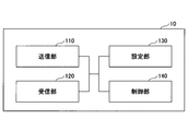
- FIG. 8 is a diagram illustrating an example of a functional configuration of the base station device 10.
- base station apparatus 10 includes transmitting section 110, receiving section 120, setting section 130, and control section 140.
- the functional configuration shown in FIG. 8 is merely an example. As long as the operation according to the embodiment of the present invention can be performed, the names of the functional divisions and the functional units may be any.
- the transmission unit 110 has a function of generating a signal to be transmitted to the user device 20 and transmitting the signal wirelessly.
- the receiving unit 120 includes a function of receiving various signals transmitted from the user device 20 and acquiring, for example, information of a higher layer from the received signals.
- the setting unit 130 stores in the storage device the setting information set in advance and various setting information to be transmitted to the user device 20, and reads out the setting information from the storage device as needed.
- the content of the setting information is, for example, information related to the setting of the D2D communication.
- the control unit 140 performs the process related to the setting for the user device 20 to perform the D2D communication, as described in the embodiment. In addition, the control unit 140 performs a process related to determining resources used for transmitting a synchronization signal and broadcast information for D2D communication. Further, the control unit 140 transmits the scheduling of the D2D communication to the user device 20 via the transmission unit 110.
- a function unit related to signal transmission in control unit 140 may be included in transmitting unit 110, and a function unit related to signal reception in control unit 140 may be included in receiving unit 120.
- FIG. 9 is a diagram illustrating an example of a functional configuration of the user device 20.
- the user device 20 includes a transmitting unit 210, a receiving unit 220, a setting unit 230, and a control unit 240.
- the functional configuration shown in FIG. 9 is only an example. As long as the operation according to the embodiment of the present invention can be performed, the names of the functional divisions and the functional units may be any.
- the transmission unit 210 creates a transmission signal from transmission data, and transmits the transmission signal wirelessly.
- the receiving unit 220 wirelessly receives various signals and obtains a higher-layer signal from the received physical-layer signal.
- the transmission unit 210 transmits the PSCCH (Physical Sidelink Shared Channel), the PSSCH (Physical Sidelink Shared Channel), the PSDCH (Physical Sidelink Discovery Channel), and the PSBCH (Physical Sidelink Broadcast Channel) to another user device 20 as D2D communication. )
- the receiving unit 220 receives a PSCCH, a PSSCH, a PSDCH, a PSBCH, or the like from another user apparatus 20.
- the setting unit 230 stores various setting information received from the base station device 10 or the user device 20 by the receiving unit 220 in a storage device, and reads out the setting information from the storage device as needed.
- the setting unit 230 also stores preset setting information.
- the content of the setting information is, for example, information related to the setting of the D2D communication.
- the control unit 240 controls the D2D communication with another user device 20 as described in the embodiment. In addition, the control unit 240 performs processing related to determination of resources used for transmitting a synchronization signal and broadcast information for D2D communication. Further, the control unit 240 may execute scheduling of D2D communication. A function unit related to signal transmission in control unit 240 may be included in transmission unit 210, and a function unit related to signal reception in control unit 240 may be included in reception unit 220.
- each functional block may be realized using one device physically or logically coupled, or directly or indirectly (for example, two or more devices physically or logically separated). , Wired, wireless, etc.), and may be implemented using these multiple devices.
- the functional block may be realized by combining one device or the plurality of devices with software.
- Functions include judgment, decision, judgment, calculation, calculation, processing, derivation, investigation, search, confirmation, reception, transmission, output, access, resolution, selection, selection, establishment, comparison, assumption, expectation, deemed, Broadcasting, notifying, communicating, forwarding, configuring, reconfiguring, allocating, mapping, assigning, but not limited to these I can't.
- a functional block (configuration unit) that causes transmission to function is called a transmitting unit (transmitting unit) or a transmitter (transmitter).
- the realization method is not particularly limited.
- the base station device 10, the user device 20, and the like may function as a computer that performs processing of the wireless communication method according to the present disclosure.
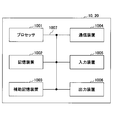
- FIG. 10 is a diagram illustrating an example of a hardware configuration of the base station device 10 and the user device 20 according to an embodiment of the present disclosure.
- the above-described base station device 10 and user device 20 are physically configured as computer devices including a processor 1001, a storage device 1002, an auxiliary storage device 1003, a communication device 1004, an input device 1005, an output device 1006, a bus 1007, and the like. May be done.
- the term “apparatus” can be read as a circuit, a device, a unit, or the like.
- the hardware configurations of the base station device 10 and the user device 20 may be configured to include one or more of the devices illustrated in the drawing, or may be configured without including some devices.
- the functions of the base station device 10 and the user device 20 are performed by reading predetermined software (program) on hardware such as the processor 1001 and the storage device 1002 so that the processor 1001 performs an arithmetic operation and the communication by the communication device 1004 is performed. This is realized by controlling, or controlling at least one of reading and writing of data in the storage device 1002 and the auxiliary storage device 1003.
- the processor 1001 controls the entire computer by operating an operating system, for example.
- the processor 1001 may be configured by a central processing unit (CPU: Central Processing Unit) including an interface with a peripheral device, a control device, an arithmetic device, a register, and the like.
- CPU Central Processing Unit
- the control unit 140, the control unit 240, and the like described above may be realized by the processor 1001.
- the processor 1001 reads a program (program code), a software module, data, or the like from at least one of the auxiliary storage device 1003 and the communication device 1004 to the storage device 1002, and executes various processes according to these.
- a program program that causes a computer to execute at least a part of the operation described in the above embodiment is used.
- the control unit 140 of the base station device 10 illustrated in FIG. 8 may be realized by a control program stored in the storage device 1002 and operated by the processor 1001.
- the control unit 240 of the user device 20 illustrated in FIG. 9 may be realized by a control program stored in the storage device 1002 and operated by the processor 1001.
- Processor 1001 may be implemented by one or more chips. Note that the program may be transmitted from a network via a telecommunication line.
- the storage device 1002 is a computer-readable recording medium, and includes, for example, at least one of a ROM (Read Only Memory), an EPROM (Erasable Programmable ROM), an EEPROM (Electrically Erasable Programmable ROM), and a RAM (Random Access Memory). It may be configured.
- the storage device 1002 may be called a register, a cache, a main memory (main storage device), or the like.
- the storage device 1002 can store a program (program code), a software module, and the like that can be executed to execute the communication method according to an embodiment of the present disclosure.
- the auxiliary storage device 1003 is a computer-readable recording medium, for example, an optical disk such as a CD-ROM (Compact Disc ROM), a hard disk drive, a flexible disk, a magneto-optical disk (for example, a compact disk, a digital versatile disk, Blu -Ray (registered trademark) disk), smart card, flash memory (eg, card, stick, key drive), floppy (registered trademark) disk, magnetic strip, or the like.
- the auxiliary storage device 1003 may be called an auxiliary storage device.
- the storage medium described above may be, for example, a database including at least one of the storage device 1002 and the auxiliary storage device 1003, a server, or another appropriate medium.
- the communication device 1004 is hardware (transmission / reception device) for performing communication between computers via at least one of a wired network and a wireless network, and is also referred to as, for example, a network device, a network controller, a network card, a communication module, or the like.
- the communication device 1004 includes a high-frequency switch, a duplexer, a filter, a frequency synthesizer, and the like, for example, in order to realize at least one of frequency division duplex (FDD: Frequency Division Duplex) and time division duplex (TDD: Time Division Duplex). May be configured.
- FDD Frequency Division Duplex
- TDD Time Division Duplex
- a transmitting / receiving antenna, an amplifier unit, a transmitting / receiving unit, a transmission line interface, and the like may be realized by the communication device 1004.
- the transmission / reception unit may be physically or logically separated from the transmission unit and the reception unit.
- the input device 1005 is an input device (for example, a keyboard, a mouse, a microphone, a switch, a button, a sensor, and the like) that receives an external input.
- the output device 1006 is an output device (for example, a display, a speaker, an LED lamp, and the like) that performs output to the outside. Note that the input device 1005 and the output device 1006 may have an integrated configuration (for example, a touch panel).
- the devices such as the processor 1001 and the storage device 1002 are connected by a bus 1007 for communicating information.
- the bus 1007 may be configured using a single bus, or may be configured using a different bus for each device.
- the base station device 10 and the user device 20 include a microprocessor, a digital signal processor (DSP), an ASIC (Application Specific Integrated Circuit), a PLD (Programmable Logic Device), an FPGA (Field Programmable Gate Array), and the like. It may be configured to include hardware, and some or all of the functional blocks may be realized by the hardware. For example, the processor 1001 may be implemented using at least one of these pieces of hardware.
- DSP digital signal processor
- ASIC Application Specific Integrated Circuit
- PLD Programmable Logic Device
- FPGA Field Programmable Gate Array
- a receiving unit that receives information indicating resources used for the downlink or the uplink from the base station device and a resource allocation for the side link are determined. And a transmitting unit for notifying a TDD configuration used for the user device.
- the user device 20 can perform appropriate SL resource allocation with a small resource overhead.
- the operation of a plurality of functional units may be physically performed by one component, or the operation of one functional unit may be physically performed by a plurality of components.
- the order of the processing may be changed unless there is a contradiction.
- the base station device 10 and the user device 20 have been described using a functional block diagram for convenience of processing description, such a device may be realized by hardware, software, or a combination thereof.
- Software operated by the processor of the base station apparatus 10 according to the embodiment of the present invention and software operated by the processor of the user apparatus 20 according to the embodiment of the present invention are a random access memory (RAM), a flash memory, and a read-only memory, respectively. (ROM), EPROM, EEPROM, register, hard disk (HDD), removable disk, CD-ROM, database, server, or any other suitable storage medium.
- notification of information is not limited to the aspect / embodiment described in the present disclosure, and may be performed using another method.
- the notification of information includes physical layer signaling (for example, DCI (Downlink Control Information), UCI (Uplink Control Information)), upper layer signaling (for example, RRC (Radio Resource Control) signaling, MAC (Medium Access Control) signaling, RRC signaling may be implemented by broadcast information (MIB (Master Information Block), SIB (System Information Block)), other signals, or a combination thereof, and RRC signaling may be called an RRC message, for example, RRC message.
- a connection setup (RRC (Connection Setup) message, an RRC connection reconfiguration (RRC Connection Reconfiguration) message, or the like may be used.
- LTE Long Term Evolution
- LTE-A Long Term Evolution-Advanced
- SUPER 3G IMT-Advanced
- 4G 4th generation mobile communication system
- 5G 5th generation mobile communication
- FRA Full Radio Access
- NR new Radio
- W-CDMA registered trademark
- GSM registered trademark
- CDMA2000 Code Division Multiple Access 2000
- UMB Universal Mobile Broadband
- IEEE 802.11 Wi-Fi (registered trademark)
- Systems using IEEE@802.16 WiMAX®
- IEEE@802.20 UWB (Ultra-WideBand
- Bluetooth® and other suitable systems and extensions based thereon. It may be applied to at least one of the next generation systems.
- a plurality of systems may be combined (for example, a combination of at least one of LTE and LTE-A with 5G) and applied.
- the specific operation described as being performed by the base station device 10 in this specification may be performed by an upper node (upper node) in some cases.
- an upper node In a network including one or a plurality of network nodes (network @ nodes) having the base station device 10, various operations performed for communication with the user device 20 are performed by the base station device 10 and other operations other than the base station device 10. It is clear that this can be done by at least one of the following network nodes (for example, but not limited to MME or S-GW, etc.).
- MME Mobility Management Entity
- ⁇ Information, signals, and the like described in the present disclosure can be output from an upper layer (or lower layer) to a lower layer (or upper layer). Input and output may be performed via a plurality of network nodes.
- the input and output information may be stored in a specific place (for example, a memory) or may be managed using a management table. Information that is input and output can be overwritten, updated, or added. The output information or the like may be deleted. The input information or the like may be transmitted to another device.
- the determination in the present disclosure may be performed by a value represented by 1 bit (0 or 1), may be performed by a Boolean value (Boolean: true or false), or may be compared by numerical values (for example, , Comparison with a predetermined value).
- software, instructions, information, and the like may be transmitted and received via a transmission medium.
- a transmission medium For example, if the software uses at least one of wired technology (coaxial cable, fiber optic cable, twisted pair, digital subscriber line (DSL), etc.) and wireless technology (infrared, microwave, etc.), the website, When transmitted from a server or other remote source, at least one of these wired and / or wireless technologies is included within the definition of a transmission medium.
- the information, signals, etc. described in this disclosure may be represented using any of a variety of different technologies.
- data, instructions, commands, information, signals, bits, symbols, chips, etc. that can be referred to throughout the above description are not limited to voltages, currents, electromagnetic waves, magnetic or magnetic particles, optical or photons, or any of these. May be represented by a combination of
- At least one of the channel and the symbol may be a signal (signaling).
- the signal may be a message.
- a component carrier (CC: Component @ Carrier) may be called a carrier frequency, a cell, a frequency carrier, or the like.
- system and “network” used in this disclosure are used interchangeably.
- the information, parameters, and the like described in the present disclosure may be expressed using an absolute value, may be expressed using a relative value from a predetermined value, or may be expressed using another corresponding information. May be represented.
- the radio resource may be indicated by an index.
- base station (BS: Base @ Station)”, “wireless base station”, “base station device”, “fixed station (fixed @ station)”, “NodeB”, “eNodeB (eNB)”, “gNodeB” (GNB) ",” access point (access @ point) “,” transmission point (transmission @ point) “,” reception point (reception @ point) “,” transmission / reception point (transmission / reception @ point) “,” cell “,” sector “, Terms such as “cell group”, “carrier”, “component carrier” may be used interchangeably.
- a base station may also be referred to as a macro cell, a small cell, a femto cell, a pico cell, or the like.
- a base station can accommodate one or more (eg, three) cells. If the base station accommodates multiple cells, the entire coverage area of the base station can be partitioned into multiple smaller areas, each smaller area being a base station subsystem (eg, a small indoor base station (RRH: The communication service can also be provided by Remote @ Radio @ Head.
- RRH small indoor base station
- the communication service can also be provided by Remote @ Radio @ Head.
- Cell or “sector” is a part or the whole of the coverage area of at least one of the base station and the base station subsystem that provides the communication service in this coverage. Point to.
- MS mobile station
- UE user equipment
- terminal terminal
- a mobile station can be a subscriber station, mobile unit, subscriber unit, wireless unit, remote unit, mobile device, wireless device, wireless communication device, remote device, mobile subscriber station, access terminal, mobile terminal, wireless terminal, by one of ordinary skill in the art. It may also be called a terminal, a remote terminal, a handset, a user agent, a mobile client, a client, or some other suitable term.
- At least one of the base station and the mobile station may be called a transmitting device, a receiving device, a communication device, or the like.
- at least one of the base station and the mobile station may be a device mounted on the mobile unit, the mobile unit itself, or the like.
- the moving object may be a vehicle (for example, a car, an airplane, or the like), may be an unmanned moving object (for example, a drone, an autonomous vehicle), or may be a robot (maned or unmanned). ).
- at least one of the base station and the mobile station includes a device that does not necessarily move during a communication operation.
- at least one of the base station and the mobile station may be an IoT (Internet of Things) device such as a sensor.
- IoT Internet of Things
- the base station in the present disclosure may be replaced with a user terminal.
- communication between a base station and a user terminal is replaced with communication between a plurality of user devices 20 (for example, it may be called D2D (Device-to-Device), V2X (Vehicle-to-Everything), etc.).
- D2D Device-to-Device
- V2X Vehicle-to-Everything
- Each aspect / embodiment of the present disclosure may be applied to the configuration described above.
- the configuration may be such that the user device 20 has the function of the base station device 10 described above.
- words such as “up” and “down” may be read as words corresponding to communication between terminals (for example, “side”).
- an uplink channel, a downlink channel, and the like may be replaced with a side channel.
- a user terminal in the present disclosure may be replaced by a base station.
- the configuration may be such that the base station has the function of the user terminal described above.
- determining may encompass a wide variety of operations.
- Judgment '', ⁇ decision '' for example, judgment (judging), calculation (calculating), calculation (computing), processing (processing), derivation (deriving), investigating (investigating), searching (looking up, search, inquiry) (E.g., searching in a table, database, or another data structure), ascertaining may be considered “determined", "determined", and the like.
- determining” and “deciding” include receiving (eg, receiving information), transmitting (eg, transmitting information), input (input), output (output), and access. (accessing) (for example, accessing data in a memory) may be regarded as “determined” or “determined”.
- ⁇ judgment '' and ⁇ decision '' means that resolving, selecting, selecting, establishing, establishing, comparing, etc. are regarded as ⁇ judgment '' and ⁇ decided ''. May be included.
- “judgment” and “decision” may include deeming any operation as “judgment” and “determined”. “Judgment (determination)” may be read as “assuming”, “expecting”, “considering”, or the like.
- connection means any direct or indirect connection or connection between two or more elements that It may include the presence of one or more intermediate elements between the two elements “connected” or “coupled.”
- the coupling or connection between the elements may be physical, logical, or a combination thereof.
- connection may be read as “access”.
- two elements may be implemented using at least one of one or more wires, cables, and printed electrical connections, and as some non-limiting and non-exhaustive examples, in the radio frequency domain. , Can be considered “connected” or “coupled” to each other using electromagnetic energy having wavelengths in the microwave and optical (both visible and invisible) regions, and the like.
- the reference signal may be abbreviated as RS (Reference Signal), and may be referred to as a pilot depending on an applied standard.
- RS Reference Signal
- references to elements using designations such as “first,” “second,” etc., as used in this disclosure, does not generally limit the quantity or order of those elements. These designations may be used in the present disclosure as a convenient way to distinguish between two or more elements. Thus, references to first and second elements do not mean that only two elements can be employed, or that the first element must precede the second element in some way.
- a radio frame may be composed of one or more frames in the time domain.
- One or more each frame in the time domain may be referred to as a subframe.
- a subframe may be further configured by one or more slots in the time domain.
- the subframe may be a fixed time length (eg, 1 ms) that does not depend on numerology.
- Numerology may be a communication parameter applied to at least one of transmission and reception of a certain signal or channel.
- Numerology includes, for example, a subcarrier interval (SCS: SubCarrier @ Spacing), a bandwidth, a symbol length, a cyclic prefix length, a transmission time interval (TTI: Transmission @ Time @ Interval), the number of symbols per TTI, a radio frame configuration, and a transceiver.
- SCS SubCarrier @ Spacing
- TTI Transmission @ Time @ Interval
- TTI Transmission @ Time @ Interval
- At least one of a specific filtering process performed in a frequency domain and a specific windowing process performed by a transceiver in a time domain may be indicated.
- the slot may be composed of one or a plurality of symbols (OFDM (Orthogonal Frequency Division Multiplexing) symbol, SC-FDMA (Single Carrier Frequency Division Multiple Access) symbol, etc.) in the time domain.
- a slot may be a time unit based on numerology.
- the slot may include a plurality of mini slots.
- Each minislot may be constituted by one or more symbols in the time domain.
- the mini-slot may be called a sub-slot.
- a minislot may be made up of a smaller number of symbols than slots.
- a PDSCH (or PUSCH) transmitted in time units larger than minislots may be referred to as PDSCH (or PUSCH) mapping type A.
- a PDSCH (or PUSCH) transmitted using a minislot may be referred to as a PDSCH (or PUSCH) mapping type B.
- Radio frames, subframes, slots, minislots, and symbols all represent time units when transmitting signals.
- the radio frame, the subframe, the slot, the minislot, and the symbol may have different names corresponding to each.
- one subframe may be called a transmission time interval (TTI: Transmission @ Time @ Interval)
- TTI Transmission @ Time @ Interval
- TTI Transmission Time interval
- a plurality of consecutive subframes may be called a TTI
- one slot or one minislot is called a TTI.
- You may. That is, at least one of the subframe and the TTI may be a subframe (1 ms) in the existing LTE, a period shorter than 1 ms (for example, 1 to 13 symbols), or a period longer than 1 ms. It may be.
- the unit representing the TTI may be called a slot, a minislot, or the like instead of a subframe.
- the TTI refers to, for example, a minimum time unit of scheduling in wireless communication.
- the base station performs scheduling for allocating radio resources (frequency bandwidth, transmission power, and the like that can be used in each user device 20) to each user device 20 in TTI units.
- radio resources frequency bandwidth, transmission power, and the like that can be used in each user device 20
- TTI is not limited to this.
- the TTI may be a transmission time unit such as a channel-encoded data packet (transport block), a code block, or a code word, or may be a processing unit such as scheduling and link adaptation. Note that when a TTI is given, a time section (for example, the number of symbols) in which a transport block, a code block, a codeword, and the like are actually mapped may be shorter than the TTI.
- one slot or one minislot is called a TTI
- one or more TTIs may be the minimum time unit for scheduling. Further, the number of slots (mini-slot number) constituting the minimum time unit of the scheduling may be controlled.
- a TTI having a time length of 1 ms may be referred to as a normal TTI (TTI in LTE@Rel.8-12), a normal TTI, a long TTI, a normal subframe, a normal subframe, a long subframe, a slot, and the like.
- a TTI shorter than the normal TTI may be called a shortened TTI, a short TTI, a partial TTI (partial or fractional TTI), a shortened subframe, a short subframe, a minislot, a subslot, a slot, and the like.
- a long TTI (for example, a normal TTI, a subframe, etc.) may be read as a TTI having a time length exceeding 1 ms, and a short TTI (for example, a shortened TTI, etc.) may be replaced with a TTI shorter than the long TTI and 1 ms.
- the TTI having the above-mentioned TTI length may be read.
- the resource block (RB) is a resource allocation unit in the time domain and the frequency domain, and may include one or a plurality of continuous subcarriers in the frequency domain.
- the number of subcarriers included in the RB may be the same regardless of the numerology, and may be, for example, 12.
- the number of subcarriers included in the RB may be determined based on numerology.
- the time domain of the RB may include one or more symbols, and may be one slot, one minislot, one subframe, or one TTI.
- One TTI, one subframe, and the like may each be configured with one or a plurality of resource blocks.
- one or more RBs include a physical resource block (PRB: Physical @ RB), a subcarrier group (SCG: Sub-Carrier @ Group), a resource element group (REG: Resource @ Element @ Group), a PRB pair, an RB pair, and the like. May be called.
- PRB Physical @ RB
- SCG Sub-Carrier @ Group
- REG Resource @ Element @ Group
- PRB pair an RB pair, and the like. May be called.
- a resource block may be composed of one or more resource elements (RE: Resource @ Element).
- RE Resource @ Element
- one RE may be a radio resource area of one subcarrier and one symbol.
- a ⁇ bandwidth part (which may be referred to as a partial bandwidth or the like) may represent a subset of consecutive common RBs (common resource blocks) for a certain numerology in a certain carrier.
- the common RB may be specified by an index of the RB based on the common reference point of the carrier.
- a PRB may be defined by a BWP and numbered within the BWP.
- $ BWP may include a BWP for UL (UL @ BWP) and a BWP for DL (DL @ BWP).
- BWP for a UE, one or more BWPs may be configured in one carrier.
- At least one of the configured BWPs may be active, and the UE does not have to assume to transmit and receive a given signal / channel outside the active BWP.
- “cell”, “carrier”, and the like in the present disclosure may be replaced with “BWP”.
- the structures of the above-described radio frames, subframes, slots, minislots, and symbols are merely examples.
- the number of subframes included in a radio frame, the number of slots per subframe or radio frame, the number of minislots included in a slot, the number of symbols and RBs included in a slot or minislot, included in an RB The configuration of the number of subcarriers, the number of symbols in the TTI, the symbol length, the cyclic prefix (CP: Cyclic @ Prefix) length, and the like can be variously changed.
- the term “A and B are different” may mean that “A and B are different from each other”.
- the term may mean that “A and B are different from C”.
- Terms such as “separate”, “coupled” and the like may be interpreted similarly to "different”.
- Each aspect / embodiment described in the present disclosure may be used alone, may be used in combination, or may be used by switching with execution. Further, the notification of the predetermined information (for example, the notification of “X”) is not limited to being explicitly performed, and is performed implicitly (for example, not performing the notification of the predetermined information). Is also good.
Landscapes
- Engineering & Computer Science (AREA)
- Signal Processing (AREA)
- Computer Networks & Wireless Communication (AREA)
- Databases & Information Systems (AREA)
- Mobile Radio Communication Systems (AREA)
Abstract
A user device according to the present invention includes: a receiving unit that receives, from a base station device, information indicating a resource used for a downlink or an uplink; and a sending unit that sends a notification of TDD configuration information used to determine the allocation of resources used for a sidelink.
Description
本発明は、無線通信システムにおけるユーザ装置に関する。
<< The present invention relates to a user apparatus in a wireless communication system.
LTE(Long Term Evolution)及びLTEの後継システム(例えば、LTE-A(LTE Advanced)、NR(New Radio)(5Gともいう。))では、ユーザ装置同士が基地局装置を介さないで直接通信を行うD2D(Device to Device)技術が検討されている(例えば非特許文献1)。
In LTE (Long Term Evolution) and a successor system to LTE (for example, LTE-A (LTE Advanced), NR (New Radio) (also referred to as 5G)), user devices directly communicate with each other without passing through a base station device. A D2D (Device @ to \ Device) technique to be performed has been studied (for example, Non-Patent Document 1).
D2Dは、ユーザ装置と基地局装置との間のトラフィックを軽減し、災害時等に基地局装置が通信不能になった場合でもユーザ装置間の通信を可能とする。なお、3GPP(3rd Generation Partnership Project)では、D2Dを「サイドリンク(sidelink)」と称しているが、本明細書では、より一般的な用語であるD2Dを使用する。ただし、後述する実施形態の説明では必要に応じてサイドリンクという用語も使用する。
D2D reduces traffic between a user apparatus and a base station apparatus, and enables communication between user apparatuses even when the base station apparatus becomes unable to communicate during a disaster or the like. In 3GPP (3rd Generation Partnership Project), D2D is referred to as “sidelink”, but in this specification, D2D which is a more general term is used. However, in the description of the embodiment described later, the term “side link” is also used as necessary.
D2D通信は、通信可能な他のユーザ装置を発見するためのD2Dディスカバリ(D2D discovery、D2D発見ともいう。)と、ユーザ装置間で直接通信するためのD2Dコミュニケーション(D2D direct communication、D2D通信、端末間直接通信等ともいう。)と、に大別される。以下では、D2Dコミュニケーション、D2Dディスカバリ等を特に区別しないときは、単にD2Dと呼ぶ。また、D2Dで送受信される信号を、D2D信号と呼ぶ。NRにおけるV2X(Vehicle to Everything)に係るサービスの様々なユースケースが検討されている(例えば非特許文献2)。
D2D communication includes D2D discovery (D2D @ discovery, also referred to as D2D discovery) for discovering another communicable user device, and D2D communication (D2D @ direct @ communication, D2D communication, terminal for direct communication between user devices). Inter-direct communication, etc.). In the following, D2D communication, D2D discovery, and the like are simply referred to as D2D unless otherwise distinguished. A signal transmitted and received in D2D is called a D2D signal. Various use cases of a service related to V2X (Vehicle to Everything) in NR are being studied (for example, Non-Patent Document 2).
LTEにおけるV2Xでは、SLSS(サイドリンクによる同期信号)やPSBCH(サイドリンクによるPBCH、報知情報)がUEによって送信され、当該UEは同期ソースとなることができる。
In V2X in TELTE, SLSS (synchronization signal by side link) and PSBCH (PBCH by side link, broadcast information) are transmitted by the UE, and the UE can be a synchronization source.
また、LTEのPSBCHでは、サイドリンク用リソース配置(SL用リソース配置)を決定するためにTDD configurationを通知している。
Further, in the LTE PSBCH, TDD @ configuration is notified in order to determine the resource allocation for the side link (the resource allocation for the SL).
LTEに比べてTDD configurationの柔軟な設定が可能なNRでは、通知に必要なビット数が多いため、ユーザ装置がPSBCHでTDD configurationを通知するためにはリソースのオーバーヘッド等が大きくなることが懸念される。
In NR where TDD @ configuration can be set flexibly as compared with LTE, the number of bits required for notification is large, so there is a concern that resource overhead and the like will increase if the user equipment notifies TDD @ configuration via PSBCH. You.
本発明は上記の点に鑑みてなされたものであり、少ないリソースオーバーヘッドで適切なSL送信用リソースの配置を行うことを可能とすることを目的とする。
The present invention has been made in view of the above points, and has as its object to enable appropriate allocation of SL transmission resources with a small resource overhead.
開示の技術によれば、下りリンク又は上りリンクに使用されるリソースを示す情報を基地局装置から受信する受信部と、サイドリンクに使用されるリソースの配置を決定するために使用されるTDD構成情報を通知する送信部とを有するユーザ装置が提供される。
According to the disclosed technology, a receiving unit that receives information indicating resources used for a downlink or an uplink from a base station device, and a TDD configuration used to determine an arrangement of resources used for a side link There is provided a user apparatus having a transmitting unit for notifying information.
開示の技術によれば、少ないリソースオーバーヘッドで適切なSL送信用リソースの配置を行うことが可能となる。
According to the disclosed technology, it is possible to appropriately allocate resources for SL transmission with a small resource overhead.
以下、図面を参照して本発明の実施形態を説明する。なお、以下で説明する実施形態は一例であり、本発明が適用される実施形態は、以下の実施形態に限られない。
Hereinafter, embodiments of the present invention will be described with reference to the drawings. The embodiment described below is an example, and the embodiment to which the present invention is applied is not limited to the following embodiment.
本発明の実施形態の無線通信システムの動作にあたっては、適宜、既存技術が使用される。ただし、当該既存技術は、例えば既存のLTEであるが、既存のLTEに限られない。また、本明細書で使用する用語「LTE」は、特に断らない限り、LTE-Advanced、及び、LTE-Advanced以降の方式(例:NR)、又は無線LAN(Local Area Network)を含む広い意味を有するものとする。
既存 In the operation of the wireless communication system according to the embodiment of the present invention, existing technology is used as appropriate. However, the existing technology is, for example, existing LTE, but is not limited to existing LTE. Further, the term “LTE” used in this specification has a broad meaning including LTE-Advanced, and systems after LTE-Advanced (eg, NR) or wireless LAN (Local Area Network) unless otherwise specified. Shall have.
また、本発明の実施形態において、複信(Duplex)方式は、TDD(Time Division Duplex)方式でもよいし、FDD(Frequency Division Duplex)方式でもよいし、又はそれ以外(例えば、Flexible Duplex等)の方式でもよい。
Further, in the embodiment of the present invention, the duplex (Duplex) method may be a TDD (Time Division Division Duplex) method, an FDD (Frequency Division Division Duplex) method, or any other method (for example, Flexible Duplex). The method may be used.
また、本発明の実施形態において、無線パラメータ等が「設定される(Configure)」とは、所定の値が予め設定(Pre-configure)されることであってもよいし、基地局装置又はユーザ装置から通知される無線パラメータが設定されることであってもよい。
Further, in the embodiment of the present invention, the “configured” of the wireless parameter or the like may mean that a predetermined value is set (Pre-configured) in advance, or the base station device or the user The wireless parameter notified from the device may be set.
図1は、V2Xを説明するための図である。3GPPでは、D2D機能を拡張することでV2X(Vehicle to Everything)あるいはeV2X(enhanced V2X)を実現することが検討され、仕様化が進められている。図1に示されるように、V2Xとは、ITS(Intelligent Transport Systems)の一部であり、自動車間で行われる通信形態を意味するV2V(Vehicle to Vehicle)、自動車と道路脇に設置される路側機(RSU:Road-Side Unit)との間で行われる通信形態を意味するV2I(Vehicle to Infrastructure)、自動車とドライバが所持するモバイル端末との間で行われる通信形態を意味するV2N(Vehicle to Nomadic device)、及び、自動車と歩行者が所持するモバイル端末との間で行われる通信形態を意味するV2P(Vehicle to Pedestrian)の総称である。
FIG. 1 is a diagram for explaining V2X. In 3GPP, realization of V2X (Vehicle to Everything) or eV2X (enhanced V2X) by expanding the D2D function has been studied, and specifications are being promoted. As shown in FIG. 1, V2X is a part of ITS (Intelligent Transport Systems), and means V2V (Vehicle to Vehicle), which means a form of communication performed between cars, and a roadside installed on the side of a car and a road. V2I (Vehicle to Infrastructure), which means a form of communication performed between the vehicle (RSU: Road-Side @ Unit), and V2N (Vehicle toto), which means a form of communication performed between an automobile and a mobile terminal possessed by a driver. Nomadic device, and V2P (Vehicle to Pedestrian) meaning a form of communication between a car and a mobile terminal carried by a pedestrian.
また、3GPPにおいて、LTE又はNRのセルラ通信及び端末間通信を用いたV2Xが検討されている。LTE又はNRのV2Xについて、今後3GPP仕様に限られない検討も進められることが想定される。例えば、インターオペラビリティの確保、上位レイヤの実装によるコストの低減、複数RAT(Radio Access Technology)の併用又は切替方法、各国におけるレギュレーション対応、LTE又はNRのV2Xプラットフォームのデータ取得、配信、データベース管理及び利用方法が検討されることが想定される。
Also, 3GPP is studying V2X using LTE or NR cellular communication and terminal-to-terminal communication. It is assumed that studies on L2 or NR V2X not limited to the 3GPP specifications will be made in the future. For example, ensuring interoperability, reducing costs by implementing higher layers, using or switching multiple RATs (Radio Access Technology), supporting regulations in each country, acquiring data from LTE or NR V2X platforms, distributing, managing databases, It is assumed that usage methods will be considered.
本発明の実施形態において、通信装置が車両に搭載される形態を主に想定するが、本発明の実施形態は、当該形態に限定されない。例えば、通信装置は人が保持する端末であってもよいし、通信装置がドローンあるいは航空機に搭載される装置であってもよいし、通信装置が基地局、RSU、中継局(リレーノード)、スケジューリング能力を有するユーザ装置等であってもよい。
に お い て In the embodiment of the present invention, a form in which the communication device is mounted on a vehicle is mainly assumed, but the embodiment of the present invention is not limited to this form. For example, the communication device may be a terminal held by a person, the communication device may be a device mounted on a drone or an aircraft, the communication device may be a base station, an RSU, a relay station (relay node), It may be a user device having scheduling capability.
なお、SL(Sidelink)は、UL(Uplink)又はDL(Downlink)と以下1)-4)のいずれか又は組み合わせに基づいて区別されてもよい。また、SLは、他の名称であってもよい。
1)時間領域のリソース配置
2)周波数領域のリソース配置
3)参照する同期信号(SLSS(Sidelink Synchronization Signal)を含む)
4)送信電力制御のためのパスロス測定に用いる参照信号
なお、本発明の実施形態におけるスロットは、ミニスロット、サブフレーム、無線フレーム、TTI(Transmission Time Interval)と読み替えられてもよい。また、本発明の実施形態におけるセルは、セルグループ、キャリアコンポーネント、BWP、リソースプール、リソース、RAT(Radio Access Technology)、システム(無線LAN含む)等に読み替えられてもよい。 Note that SL (Sidelink) may be distinguished from UL (Uplink) or DL (Downlink) based on any one or combination of the following 1) -4). SL may be another name.
1) Resource allocation in time domain 2) Resource allocation in frequency domain 3) Reference synchronization signal (including SLSS (Sidelink Synchronization Signal))
4) Reference signal used for path loss measurement for transmission power control Note that a slot in the embodiment of the present invention may be read as a minislot, a subframe, a radio frame, or a TTI (Transmission Time Interval). Further, the cell in the embodiment of the present invention may be read as a cell group, a carrier component, a BWP, a resource pool, a resource, a RAT (Radio Access Technology), a system (including a wireless LAN), or the like.
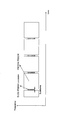
図2は、サイドリンクの同期信号及び報知情報の配置例を説明するための図である。LTE V2Xでは、同期信号であるSLSS(Sidelink synchronization signal)及び報知情報が送信されるチャネルであるPSBCH(Physical Sidelink Broadcast Channel)がユーザ装置によって送信され、他のユーザ装置は、当該SLSSを送信するユーザ装置を同期ソースとして用いることができる。
FIG. 2 is a diagram for explaining an example of arrangement of a synchronization signal and broadcast information of a side link. In LTE @ V2X, a user equipment transmits an SLSS (Sidelink @ synchronization @ signal) which is a synchronization signal and a PSBCH (Physical @ Sidelink @ Broadcast @ Channel) which is a channel through which broadcast information is transmitted, and the other user apparatuses transmit the SLSS to the user. The device can be used as a synchronization source.
図2に示されるように、LTE V2XにおけるSLSS及びPSBCHの送信機会(SLSS/PSBCH occasion)は、サブフレーム(Subframe)全体を占有する。PSCCH(Physical Sidelink Control Channel)又はPSSCH(Physical Sidelink Shared Channel)は、SLSS及びPSBCHの送信機会と時間領域では多重されない。
よ う As shown in FIG. 2, the transmission opportunity (SLSS / PSBCH occasion) of SLSS and PSBCH in LTE V2X occupies the entire subframe (Subframe). PSCCH (Physical Sidelink Control Channel) or PSSCH (Physical Sidelink Shared Channel) is not multiplexed in the time domain with the transmission opportunity of SLSS and PSBCH.
NR V2Xでは、サイドリンクの同期処理に係る信号は、SLSS及びPSBCHを含むことが検討されている。また、同期ソースは、例えば、GNSS(Global Navigation Satellite System)、gNB(Next generation Node-B)、eNB(enhanced Node-B)、NR-UE(User Equipment)又はLTE-UEであってもよい。
In NR V2X, it is studied that the signal related to the side link synchronization processing includes SLSS and PSBCH. In addition, the synchronization source may be, for example, GNSS (Global Navigation Satellite System), gNB (Next Generation Node-B), eNB (enhanced Node-B), NR-UE (User Equipment), or LTE-UE.
SLSSやPSBCHに相当するものを含んだものをSL SS block、SL SS/PBCH block、SL SS/PSBCH block等と呼んでもよい。本明細書では、通常SL SSBと呼ぶ。SL SSBにはDM RS等も一緒に含まれていてもよい。
What includes the equivalent to $ SLSS or PSBCH may be called SL @ SS @ block, SL @ SS / PBCH @ block, SL @ SS / PSBCH @ block, or the like. In this specification, it is usually called SL @ SSB. SL @ SSB may also include DM @ RS and the like.
図3は、本発明の実施形態における無線通信システムの例を示す図である。NR V2Xにおいて、SL-SSBの送信に必要となるリソース量が大きくなる可能性がある。そこで、例えば、DL又はULで既に配置されているチャネルのリソースを使用して、ユーザ装置20Aは、SL-SSBを送信してもよい。DL又はULで既に配置されているチャネルのリソースを使用することで、新たにSL-SSB専用のリソースを確保せずに、ユーザ装置20Aは、SL-SSBを送信することが可能になる。
FIG. 3 is a diagram showing an example of a wireless communication system according to the embodiment of the present invention. In NR V2X, there is a possibility that the amount of resources required for SL-SSB transmission is increased. Therefore, for example, the user apparatus 20A may transmit the SL-SSB using the resources of the channel that is already arranged in the DL or the UL. By using the resources of the channel already arranged in DL or UL, the user device 20A can transmit the SL-SSB without newly securing a dedicated resource for the SL-SSB.
図3に示されるように、基地局装置10Aのカバレッジ内に位置するユーザ装置20Aは、DL-SSBを基地局装置10Aから受信する。ユーザ装置20Aは、SL-SSBをカバレッジ外に位置するユーザ装置20Bに送信する。さらに、ユーザ装置20Bは、カバレッジ外に位置する他のユーザ装置20BにSL-SSBを送信してもよい。
(3) As shown in FIG. 3, the user apparatus 20A located within the coverage of the base station apparatus 10A receives the DL-SSB from the base station apparatus 10A. The user device 20A transmits the SL-SSB to the user device 20B located outside the coverage. Further, the user device 20B may transmit the SL-SSB to another user device 20B located outside the coverage.
図4は、本発明の実施形態における無線通信システムの他の例を示す図である。図4に示される例では、カバレッジ外に位置するユーザ装置20CのメモリやSIMには、予め設定されたSL-SSBリソース情報等が格納されている。ユーザ装置20Cは、予め設定されたSL-SSBリソース情報等に基づいて、SL-SSBをカバレッジ外に位置する他のユーザ装置20D、20Eに送信する。
FIG. 4 is a diagram showing another example of the wireless communication system according to the embodiment of the present invention. In the example shown in FIG. 4, preset memory such as SL-SSB resource information is stored in the memory or the SIM of the user device 20C located outside the coverage. The user device 20C transmits the SL-SSB to the other user devices 20D and 20E located outside the coverage based on the preset SL-SSB resource information and the like.
図5は、LTEにおけるTDD configurationの通知用の情報要素を示す図である。情報要素TDD-Configの中のパラメータTDD-ConfigSLは、サイドリンク用のTDD Configurationの通知に用いられるパラメータであり、パラメータTDD-ConfigSLに設定される値sa0乃至sa6は、TDD Configurationのパターンを示している。LTEでは、TDD Configurationのパターンの数は限られているので、比較的少ないビット数で通知することができることがわかる。
FIG. 5 is a diagram showing information elements for notification of TDD configuration in LTE. The parameter TDD-ConfigSL in the information element TDD-Config is a parameter used for notification of TDD @ Configuration for the side link, and the values sa0 to sa6 set in the parameter TDD-ConfigSL indicate the pattern of TDD @ Configuration. I have. In LTE, since the number of TDD @ Configuration patterns is limited, it can be seen that notification can be made with a relatively small number of bits.
図6は、NRにおけるTDD configuration通知用の情報要素を示す図である。図6に示すように、情報要素TDD-UL-DL-ConfigにはTDD-UL-DL-ConfigCommonやTDD-UL-DL-ConfigDedicated等が含まれており、さまざまなパラメータを用いて柔軟な設定をすることが可能である。
FIG. 6 is a diagram showing information elements for TDD @ configuration notification in NR. As shown in FIG. 6, the information element TDD-UL-DL-Config includes TDD-UL-DL-ConfigCommon, TDD-UL-DL-ConfigDedicated, and the like, so that flexible settings can be made using various parameters. It is possible to
例えば、TDD構成共通情報であるTDD-UL-DL-ConfigCommonには、サブキャリアスペーシングやDL-ULのConfigurationパターン情報が含まれ、該パターン情報には、DL-ULパターンの周期情報、DL-ULパターンにおけるDLスロット数、DLシンボル数、ULスロット数、ULシンボル数等を設定する情報が含まれる。更に、異なる二つのパターン情報を設定できるようになっており,それらが連続的に配置される。また、TDD-UL-DL-ConfigDedicatedには、TDD-UL-DL-ConfigCommonよりも詳細に、各スロット内のDL-ULパターン等を設定可能となっている。
For example, TDD-UL-DL-ConfigCommon, which is TDD configuration common information, includes sub-carrier spacing and DL-UL Configuration pattern information, and the pattern information includes DL-UL pattern cycle information, DL-UL Information for setting the number of DL slots, the number of DL symbols, the number of UL slots, the number of UL symbols, and the like in the UL pattern is included. Further, two different pieces of pattern information can be set, and they are continuously arranged. Further, in TDD-UL-DL-ConfigDedicated, a DL-UL pattern or the like in each slot can be set in more detail than TDD-UL-DL-ConfigCommon.
したがって、LTEに比べてNRでは、TDD configurationの通知に必要なビット数が多く、ユーザ装置がPSBCHでTDD configurationを通知するためにはリソースのオーバーヘッド等が大きくなることが懸念される。
Therefore, compared to LTE, in NR, the number of bits required for reporting TDD @ configuration is larger, and there is a concern that resource overhead and the like will increase for the user apparatus to report TDD @ configuration on PSBCH.
このような懸念を解決するために、少ないリソースオーバーヘッドで適切なSL transmission用リソースの配置(SL送信用リソースの配置)を行うことを可能とする方法を以下に示す。
{To solve such a concern, a method for arranging appropriate SL @ transmission resources (arrangement of SL transmission resources) with a small resource overhead will be described below.
(方法1)
少ないリソースオーバーヘッドで適切なSL送信用リソースの配置を行うことを可能とする方法1として、TDD-UL-DL-ConfigCommonのみを通知する方法が考えられる。方法1では、TDD-UL-DL-ConfigDedicatedは通知しなくてよい。 (Method 1)
As amethod 1 that enables appropriate allocation of SL transmission resources with a small resource overhead, a method of notifying only TDD-UL-DL-ConfigCommon can be considered. In method 1, TDD-UL-DL-ConfigDedicated need not be notified.
少ないリソースオーバーヘッドで適切なSL送信用リソースの配置を行うことを可能とする方法1として、TDD-UL-DL-ConfigCommonのみを通知する方法が考えられる。方法1では、TDD-UL-DL-ConfigDedicatedは通知しなくてよい。 (Method 1)
As a
(方法1の1)
方法1の1として、TDD-UL-DL-ConfigCommonに含まれるすべての情報(DL-ULパターンの周期情報、DL-ULパターンにおけるDLスロット数、DLシンボル数、ULスロット数、ULシンボル数等の情報のすべて)を通知することが考えられる。 (Method 1-1)
As one ofmethod 1, all information included in TDD-UL-DL-ConfigCommon (period information of DL-UL pattern, number of DL slots in DL-UL pattern, number of DL symbols, number of UL slots, number of UL symbols, etc.) Information).
方法1の1として、TDD-UL-DL-ConfigCommonに含まれるすべての情報(DL-ULパターンの周期情報、DL-ULパターンにおけるDLスロット数、DLシンボル数、ULスロット数、ULシンボル数等の情報のすべて)を通知することが考えられる。 (Method 1-1)
As one of
(方法1の2)
方法1の2として、TDD-UL-DL-ConfigCommonのうち、一部の情報を通知することが考えられる。 (Method 1-2)
As method 2 of 2, it is conceivable to notify a part of information of TDD-UL-DL-ConfigCommon.
方法1の2として、TDD-UL-DL-ConfigCommonのうち、一部の情報を通知することが考えられる。 (Method 1-2)
As method 2 of 2, it is conceivable to notify a part of information of TDD-UL-DL-ConfigCommon.
一部の情報を通知する方法として、例えば、TDD-UL-DL-ConfigCommonのうち、Periodicity(周期情報)、UplinkSlot(ULスロット数)、UplinkSymbol(ULシンボル数)に関する情報のみを通知してもよい。
As a method of notifying a part of the information, for example, of TDD-UL-DL-ConfigCommon, only information on Periodicity (period information), UplinkSlot (the number of UL slots), and UplinkSymbol (the number of UL symbols) may be notified. .
図6に示すように、情報要素TDD-UL-DL-Configでは、Configurationのパターンとして2つのパターン(pattern1、pattern2)を通知することができる。Periodicity、UplinkSlot、UplinkSymbolに関する情報を通知する場合に、pattern1とpattern2の両方について通知してもよいし、どちらか一方について通知してもよい。
情報 As shown in FIG. 6, in the information element TDD-UL-DL-Config, two patterns (pattern1, pattern2) can be notified as a configuration pattern. When notifying information on Periodicity, UplinkSlot, and UplinkSymbol, notification may be made for both pattern1 and pattern2, or for either one.
一部の情報を通知する方法として、例えば、TDD-UL-DL-ConfigCommonのうち、Periodicity、DownlinkSlot、DownlinkSymbolに関する情報のみを通知してもよい。
As a method of notifying a part of information, for example, of TDD-UL-DL-ConfigCommon, only information on Periodicity, DownlinkSlot, and DownlinkSymbol may be notified.
Periodicity、DownlinkSlot、DownlinkSymbolに関する情報を通知する場合に、pattern1とpattern2の両方について通知してもよいし、どちらか一方について通知してもよい。
When notifying information on Periodicity, DownlinkSlot, and DownlinkSymbol, it is possible to notify both of pattern1 and pattern2, or to notify either one of them.
一部の情報を通知する方法として、例えば、連続する2つのパターン(pattern1とpattern2)のそれぞれのperiodicityを通知するのではなく、それぞれのperiodicityを足し合わせた合計のperiodicityを通知し、pattern2のUplinkSlot、UplinkSymbolに関する情報を通知してもよい。
As a method of notifying a part of the information, for example, instead of notifying the respective periodicities of two consecutive patterns (pattern1 and pattern2), a total of the respective periodicities is notified, and the UplinkSlot of the pattern2 is notified. , UplinkSymbol may be notified.
一部の情報を通知する方法として、例えば、連続する2つのパターン(pattern1とpattern2)のそれぞれのperiodicityを通知するのではなく、それぞれのperiodicityを足し合わせた合計のperiodicityを通知し、pattern2のDownlinkSlot、DownlinkSymbolに関する情報を通知してもよい。
As a method of notifying a part of the information, for example, instead of notifying the respective periodicities of two consecutive patterns (pattern1 and pattern2), notifying the respective periodicities and notifying the total periodicity, a DownlinkSlot of the pattern2 is notified. , DownlinkSymbol may be notified.
一部の情報を通知する方法として、例えば、連続する2つのパターン(pattern1とpattern2)のそれぞれのperiodicityを通知するのではなく、それぞれのperiodicityを足し合わせた合計のperiodicityを通知し、pattern1もしくはpattern2の一部の情報を通知してもよい。
As a method of notifying part of the information, for example, instead of notifying the respective periodicities of two consecutive patterns (pattern1 and pattern2), a total periodicity obtained by adding the respective periodicities is notified, and pattern1 or pattern2 is used. May be notified.
(方法2)
少ないリソースオーバーヘッドで適切なSL送信用リソースの配置を行うことを可能とする方法2として、TDD-UL-DL-ConfigCommonのperiodicityを通知し、SL送信用リソースの配置の通知として、当該periodicityに対応したoffsetを通知する方法が考えられる。 (Method 2)
As a method 2 for enabling appropriate allocation of SL transmission resources with a small resource overhead, TDD-UL-DL-ConfigCommonPeriodity is notified, and the corresponding SL transmission resource allocation notification corresponds to the periodicity. A method of notifying the set offset is considered.
図7は、本発明の実施形態におけるTDD configurationの通知方法2の一例を示す図である。
FIG. 7 is a diagram illustrating an example of the notification method 2 of the TDD configuration according to the embodiment of the present invention.
図7に示される例では、通知されるTDD configurationのperiodicityは5つのスロットに対応している。そして、5つのスロットslot#0乃至#4のうち2番目のスロットであるslot#1を示すoffsetが通知される。
In the example shown in FIG. 7, the reported TDD configuration configuration period corresponds to five slots. Then, an offset indicating the slot # 1, which is the second slot among the five slots slot # 0 to slot # 4, is notified.
通知されるoffsetは、slot offsetおよびsymbol offsetの両方でもよいし、いずれか一方でもよい。
The offset to be notified may be both slot @ offset and symbol @ offset, or one of them.
SL送信用リソースには、SL SS、PSBCH、SL SSB、PSCCH、PSSCH、その他のSLチャネル用のリソースのうち、いずれか一つ、若しくは複数のリソースが含まれてもよい。
The SL transmission resource may include one or more of SL SS, PSBCH, SL SSB, PSCCH, PSSCH, and other SL channel resources.
通知されるTDD-UL-DL-ConfigCommonのperiodicityの情報は、pattern1のperiodicityおよびpattern2のperiodiciyの両方でもよいし、どちらか一方でもよい。
The information of the periodicity of the TDD-UL-DL-ConfigCommon to be notified may be both the periodicity of the pattern1 and the periodicity of the pattern2, or may be one of them.
(方法3)
少ないリソースオーバーヘッドで適切なSL送信用リソースの配置を行うことを可能とする方法3として、SL用リソースの候補位置を通知もしくは規定し、当該リソース候補位置におけるDL/X(flexible)/ULのconfiguration(構成、設定)を通知もしくは規定することが考えられる。 (Method 3)
As a method 3 that enables appropriate allocation of SL transmission resources with a small resource overhead, a candidate position of the SL resource is notified or specified, and DL / X (flexible) / UL configuration at the resource candidate position is performed. (Configuration, setting) may be notified or specified.
例えば、SL用リソースのslot位置を通知もしくは規定し、当該slot位置におけるDL/X(flexible)/ULのconfiguration(構成、設定)を通知もしくは規定する。当該slot位置におけるDL/X(flexible)/ULのconfiguration(構成、設定)の通知もしくは規定については、DLのシンボル数およびULのシンボル数のうち少なくとも一つが通知もしくは規定されてもよいし、SlotFormatIndicator(SFI)によってDL/X(flexible)/ULのconfigurationのパターンが通知もしくは規定されてもよい。通知もしくは規定される当該slot位置については、一つのスロットでもよいし、複数の連続するスロットでもよい。
For example, the slot position of the SL resource is notified or specified, and the DL / X (flexible) / UL configuration (configuration, setting) at the slot position is notified or specified. Regarding the notification or definition of the configuration (configuration, setting) of DL / X (flexible) / UL at the slot position, at least one of the number of DL symbols and the number of UL symbols may be notified or specified, or a SlotFormatIndicator. A pattern of DL / X (flexible) / UL configuration may be notified or defined by (SFI). The slot position notified or specified may be a single slot or a plurality of consecutive slots.
(方法4)
少ないリソースオーバーヘッドで適切なSL送信用リソースの配置を行うことを可能とする方法4として、実際に送信されたDL SSBの位置を通知することが考えられる。 (Method 4)
As a method 4 that enables the proper allocation of the resources for SL transmission with a small resource overhead, it is conceivable to notify the position of the DL SSB actually transmitted.
少ないリソースオーバーヘッドで適切なSL送信用リソースの配置を行うことを可能とする方法4として、実際に送信されたDL SSBの位置を通知することが考えられる。 (Method 4)
As a method 4 that enables the proper allocation of the resources for SL transmission with a small resource overhead, it is conceivable to notify the position of the DL SSB actually transmitted.
実際に送信されたDL SSBの位置を通知する方法としては、SSB群のslot offsetおよびperiodicityを用いて通知されてもよいし、SSB群の中の送信されるSSB bitmapを用いて通知されてもよいし、SSB subcarrier spacing等を用いて通知されてもよい。あるいは、DLの報知情報から得られた実際に送信されたDL SSBの通知に基づいて、同様の情報がSLによって通知されてもよい。
As a method of notifying the position of the actually transmitted DL @ SSB, the notification may be made using the slot @ offset and the periodicity of the SSB group, or may be notified using the transmitted SSB @ bitmap in the SSB group. Alternatively, the notification may be made using SSB \ subcarrier \ spacing or the like. Alternatively, similar information may be notified by the SL based on the actually transmitted notification of DL @ SSB obtained from the notification information of the DL.
(方法5)
少ないリソースオーバーヘッドで適切なSL送信用リソースの配置を行うことを可能とする方法5として、ユーザ装置20が受信(検出)できたSSBの、若しくは所定の閾値を満たしたSSBの、位置若しくはSSB index等の識別可能な情報を通知することが考えられる。 (Method 5)
As a method 5 that enables appropriate allocation of SL transmission resources with a small resource overhead, the position or the SSB index of the SSB that theuser apparatus 20 can receive (detect) or the SSB that satisfies a predetermined threshold is used. It is conceivable to notify identifiable information such as.
少ないリソースオーバーヘッドで適切なSL送信用リソースの配置を行うことを可能とする方法5として、ユーザ装置20が受信(検出)できたSSBの、若しくは所定の閾値を満たしたSSBの、位置若しくはSSB index等の識別可能な情報を通知することが考えられる。 (Method 5)
As a method 5 that enables appropriate allocation of SL transmission resources with a small resource overhead, the position or the SSB index of the SSB that the
当該SSBは、一つのSSBでもよいし複数のSSBでもよい。当該SSBは、例えばビットマップ形式で通知されてもよい。
The SSB may be one SSB or a plurality of SSBs. The SSB may be notified, for example, in a bitmap format.
所定の閾値については、測定したSSBの強度または品質の閾値でもよい。例えば、RSRP、RSRQ、SINR等に基づく閾値でもよい。所定の閾値は、L1(レイヤ1)で計測した値に基づく閾値でもよいし、計測結果がL3(レイヤ3)でfilterされた値に基づく閾値でもよい。所定の閾値は、beam単位で計測された計測結果に適用されてもよいし、cell単位で計測された計測結果に適用されてもよい。
The predetermined threshold value may be a measured SSB intensity or quality threshold value. For example, a threshold based on RSRP, RSRQ, SINR, or the like may be used. The predetermined threshold may be a threshold based on a value measured in L1 (layer 1) or a threshold based on a value obtained by filtering a measurement result in L3 (layer 3). The predetermined threshold may be applied to a measurement result measured in beam units, or may be applied to a measurement result measured in cell units.
所定の閾値は、ユーザ装置20に通知されてもよいし規定されていてもよい。
The predetermined threshold value may be notified to the user device 20 or may be specified.
なお、SL送信用リソースの配置において、上記方法1乃至方法5によって定まったDL、X、UL、SSBの割当て対して、下記(1)乃至(5)の事項のうちのいずれか一つの事項、もしくは複数の事項が適用されてもよい。
(1)UL以外の領域と重なったSL送信用リソースがSL送信用リソースから除外されてもよい。
(2)X以外の領域と重なったSL送信用リソースがSL送信用リソースから除外されてもよい。
(3)XとUL以外の領域と重なったSL送信用リソースがSL送信用リソースから除外されてもよい。
(4)実際に送信されたSSB(transmitted SSB、actually transmitted SSB)のシンボルと重なったSL送信用リソースについては、SL送信用リソースから除外されてもよい。
(5)実際に送信されたSSBのシンボル以外の領域と重なったSL送信用リソースがSL送信用リソースから除外されてもよい。 In the allocation of the SL transmission resources, any one of the following items (1) to (5) is assigned to the allocation of DL, X, UL, and SSB determined by theabove methods 1 to 5. Alternatively, a plurality of items may be applied.
(1) The resources for SL transmission overlapping with the area other than the UL may be excluded from the resources for SL transmission.
(2) The SL transmission resource overlapping the area other than X may be excluded from the SL transmission resource.
(3) The SL transmission resource that overlaps the area other than the X and the UL may be excluded from the SL transmission resource.
(4) An SL transmission resource that is overlapped with an actually transmitted SSB (transmitted SSB, actually transmitted SSB) symbol may be excluded from the SL transmission resource.
(5) The SL transmission resource overlapping with the area other than the actually transmitted SSB symbol may be excluded from the SL transmission resource.
(1)UL以外の領域と重なったSL送信用リソースがSL送信用リソースから除外されてもよい。
(2)X以外の領域と重なったSL送信用リソースがSL送信用リソースから除外されてもよい。
(3)XとUL以外の領域と重なったSL送信用リソースがSL送信用リソースから除外されてもよい。
(4)実際に送信されたSSB(transmitted SSB、actually transmitted SSB)のシンボルと重なったSL送信用リソースについては、SL送信用リソースから除外されてもよい。
(5)実際に送信されたSSBのシンボル以外の領域と重なったSL送信用リソースがSL送信用リソースから除外されてもよい。 In the allocation of the SL transmission resources, any one of the following items (1) to (5) is assigned to the allocation of DL, X, UL, and SSB determined by the
(1) The resources for SL transmission overlapping with the area other than the UL may be excluded from the resources for SL transmission.
(2) The SL transmission resource overlapping the area other than X may be excluded from the SL transmission resource.
(3) The SL transmission resource that overlaps the area other than the X and the UL may be excluded from the SL transmission resource.
(4) An SL transmission resource that is overlapped with an actually transmitted SSB (transmitted SSB, actually transmitted SSB) symbol may be excluded from the SL transmission resource.
(5) The SL transmission resource overlapping with the area other than the actually transmitted SSB symbol may be excluded from the SL transmission resource.
また、SL送信用リソースの配置を示す情報が、上記(1)乃至(5)の事項のうちいずれか一つの事項、もしくは複数の事項が適用された結果除外された領域以外の領域(すなわち、除外されなかった領域)に対する情報として適用されてもよい。
Further, the information indicating the location of the SL transmission resource may be any one of the items (1) to (5) or an area other than an area excluded as a result of applying a plurality of items (that is, It may be applied as information to the (region not excluded).
例えば、SL送信用リソースの配置を示す情報としてslot offset、symbol offset等が通知または規定された時、当該slot offset、symbol offset等は、上記(1)乃至(5)の事項のうちいずれか一つの事項、もしくは複数の事項が適用された結果除外された領域以外の領域に対するオフセットとして適用されてもよい。
For example, when a slot @ offset, a symbol @ offset, or the like is notified or specified as information indicating the location of the SL transmission resource, the slot @ offset, the symbol @ offset, or the like is one of the items (1) to (5) above. It may be applied as an offset to a region other than the region excluded as a result of applying one or a plurality of items.
具体例として、図7において、5つのスロットslot#0乃至#4の中のslot#3およびslot#4がULであり、上記(1)の事項が適用された場合を考える。
{As a specific example, in FIG. 7, let us consider a case where the slot # 3 and the slot # 4 of the five slots slot # 0 to # 4 are UL and the above item (1) is applied.
上記(1)の事項の適用により、2番目のスロットを示すoffsetは、UL以外の領域が除外された領域(slot#3およびslot#4)に対して適用されるので、slot#3およびslot#4における2番目のスロット、すなわちスロット#4がSL送信用リソースとなる。
By applying the above item (1), the offset indicating the second slot is applied to the regions (slot # 3 and slot # 4) excluding the regions other than the UL, so that the slots # 3 and slot # 4 are used. The second slot in # 4, that is, slot # 4 is the SL transmission resource.
なお、本発明の実施形態において、SL transmissionは、SL SS、PSBCH、SL SSB、PSCCH、PSSCH、その他のSLチャネルのうちのいずれか一つ、もしくは複数でもよい。
In the embodiment of the present invention, the SL transmission may be one or more of SL @ SS, PSBCH, SL @ SSB, PSCCH, PSSCH, and other SL channels.
なお、本発明の実施形態において、通知又は指定を行うシグナリングはすべて、RRC、MAC、DCI(Downlink Control Information)又はSCI(Sidelink Control Information)のいずれのシグナリングであってもよい。また、当該シグナリングは、PBCH、PDCCH、PDSCH、PSBCH、PSDCH、PSSCH、PSCCHいずれのチャネルを介して送信されてもよい。すなわち、基地局装置10からユーザ装置20はシグナリングを受信してもよいし、他のユーザ装置20からユーザ装置20はシグナリングを受信してもよい。また、当該シグナリングは、Pre-configureされたものであってもよい。例えば、当該シグナリングは、SIMカードもしくは端末に事前に書き込まれた情報に基づくものであってもよいし、過去に通知されたものを保持している情報に基づくものであってもよい。
In the embodiment of the present invention, all the signaling for notification or designation may be any of RRC, MAC, DCI (Downlink Control Information) or SCI (Sidelink Control Information) signaling. Further, the signaling may be transmitted via any of PBCH, PDCCH, PDSCH, PSBCH, PSDCH, PSSCH, and PSCCH channels. That is, the user device 20 may receive the signaling from the base station device 10, or the user device 20 may receive the signaling from another user device 20. Also, the signaling may be pre-configured. For example, the signaling may be based on information written in a SIM card or a terminal in advance, or may be based on information holding information notified in the past.
(装置構成)
次に、これまでに説明した処理及び動作を実行する基地局装置10及びユーザ装置20の機能構成例を説明する。基地局装置10及びユーザ装置20は上述した実施例を実施する機能を含む。ただし、基地局装置10及びユーザ装置20はそれぞれ、実施例の中の一部の機能のみを備えることとしてもよい。 (Device configuration)
Next, an example of a functional configuration of thebase station device 10 and the user device 20 that execute the processes and operations described above will be described. The base station device 10 and the user device 20 include a function for implementing the above-described embodiment. However, each of the base station device 10 and the user device 20 may include only some of the functions in the embodiment.
次に、これまでに説明した処理及び動作を実行する基地局装置10及びユーザ装置20の機能構成例を説明する。基地局装置10及びユーザ装置20は上述した実施例を実施する機能を含む。ただし、基地局装置10及びユーザ装置20はそれぞれ、実施例の中の一部の機能のみを備えることとしてもよい。 (Device configuration)
Next, an example of a functional configuration of the
<基地局装置10>
図8は、基地局装置10の機能構成の一例を示す図である。図8に示されるように、基地局装置10は、送信部110と、受信部120と、設定部130と、制御部140とを有する。図8に示される機能構成は一例に過ぎない。本発明の実施形態に係る動作を実行できるのであれば、機能区分及び機能部の名称はどのようなものでもよい。 <Base station device 10>
FIG. 8 is a diagram illustrating an example of a functional configuration of thebase station device 10. As shown in FIG. 8, base station apparatus 10 includes transmitting section 110, receiving section 120, setting section 130, and control section 140. The functional configuration shown in FIG. 8 is merely an example. As long as the operation according to the embodiment of the present invention can be performed, the names of the functional divisions and the functional units may be any.
図8は、基地局装置10の機能構成の一例を示す図である。図8に示されるように、基地局装置10は、送信部110と、受信部120と、設定部130と、制御部140とを有する。図8に示される機能構成は一例に過ぎない。本発明の実施形態に係る動作を実行できるのであれば、機能区分及び機能部の名称はどのようなものでもよい。 <
FIG. 8 is a diagram illustrating an example of a functional configuration of the
送信部110は、ユーザ装置20側に送信する信号を生成し、当該信号を無線で送信する機能を含む。受信部120は、ユーザ装置20から送信された各種の信号を受信し、受信した信号から、例えばより上位のレイヤの情報を取得する機能を含む。
The transmission unit 110 has a function of generating a signal to be transmitted to the user device 20 and transmitting the signal wirelessly. The receiving unit 120 includes a function of receiving various signals transmitted from the user device 20 and acquiring, for example, information of a higher layer from the received signals.
設定部130は、予め設定される設定情報、及び、ユーザ装置20に送信する各種の設定情報を記憶装置に格納し、必要に応じて記憶装置から読み出す。設定情報の内容は、例えば、D2D通信の設定に係る情報等である。
The setting unit 130 stores in the storage device the setting information set in advance and various setting information to be transmitted to the user device 20, and reads out the setting information from the storage device as needed. The content of the setting information is, for example, information related to the setting of the D2D communication.
制御部140は、実施例において説明したように、ユーザ装置20がD2D通信を行うための設定に係る処理を行う。また、制御部140は、D2D通信の同期信号及び報知情報の送信に使用するリソース決定に係る処理を行う。また、制御部140は、D2D通信のスケジューリングを送信部110を介してユーザ装置20に送信する。制御部140における信号送信に関する機能部を送信部110に含め、制御部140における信号受信に関する機能部を受信部120に含めてもよい。
The control unit 140 performs the process related to the setting for the user device 20 to perform the D2D communication, as described in the embodiment. In addition, the control unit 140 performs a process related to determining resources used for transmitting a synchronization signal and broadcast information for D2D communication. Further, the control unit 140 transmits the scheduling of the D2D communication to the user device 20 via the transmission unit 110. A function unit related to signal transmission in control unit 140 may be included in transmitting unit 110, and a function unit related to signal reception in control unit 140 may be included in receiving unit 120.
<ユーザ装置20>
図9は、ユーザ装置20の機能構成の一例を示す図である。図9に示されるように、ユーザ装置20は、送信部210と、受信部220と、設定部230と、制御部240とを有する。図9に示される機能構成は一例に過ぎない。本発明の実施形態に係る動作を実行できるのであれば、機能区分及び機能部の名称はどのようなものでもよい。 <User device 20>
FIG. 9 is a diagram illustrating an example of a functional configuration of theuser device 20. As illustrated in FIG. 9, the user device 20 includes a transmitting unit 210, a receiving unit 220, a setting unit 230, and a control unit 240. The functional configuration shown in FIG. 9 is only an example. As long as the operation according to the embodiment of the present invention can be performed, the names of the functional divisions and the functional units may be any.
図9は、ユーザ装置20の機能構成の一例を示す図である。図9に示されるように、ユーザ装置20は、送信部210と、受信部220と、設定部230と、制御部240とを有する。図9に示される機能構成は一例に過ぎない。本発明の実施形態に係る動作を実行できるのであれば、機能区分及び機能部の名称はどのようなものでもよい。 <
FIG. 9 is a diagram illustrating an example of a functional configuration of the
送信部210は、送信データから送信信号を作成し、当該送信信号を無線で送信する。受信部220は、各種の信号を無線受信し、受信した物理レイヤの信号からより上位のレイヤの信号を取得する。また、例えば、送信部210は、D2D通信として、他のユーザ装置20に、PSCCH(Physical Sidelink Control Channel)、PSSCH(Physical Sidelink Shared Channel)、PSDCH(Physical Sidelink Discovery Channel)、PSBCH(Physical Sidelink Broadcast Channel)等を送信し、受信部220は、他のユーザ装置20から、PSCCH、PSSCH、PSDCH又はPSBCH等を受信する。
(4) The transmission unit 210 creates a transmission signal from transmission data, and transmits the transmission signal wirelessly. The receiving unit 220 wirelessly receives various signals and obtains a higher-layer signal from the received physical-layer signal. In addition, for example, the transmission unit 210 transmits the PSCCH (Physical Sidelink Shared Channel), the PSSCH (Physical Sidelink Shared Channel), the PSDCH (Physical Sidelink Discovery Channel), and the PSBCH (Physical Sidelink Broadcast Channel) to another user device 20 as D2D communication. ) And the like, and the receiving unit 220 receives a PSCCH, a PSSCH, a PSDCH, a PSBCH, or the like from another user apparatus 20.
設定部230は、受信部220により基地局装置10又はユーザ装置20から受信した各種の設定情報を記憶装置に格納し、必要に応じて記憶装置から読み出す。また、設定部230は、予め設定される設定情報も格納する。設定情報の内容は、例えば、D2D通信の設定に係る情報等である。
The setting unit 230 stores various setting information received from the base station device 10 or the user device 20 by the receiving unit 220 in a storage device, and reads out the setting information from the storage device as needed. The setting unit 230 also stores preset setting information. The content of the setting information is, for example, information related to the setting of the D2D communication.
制御部240は、実施例において説明したように、他のユーザ装置20との間のD2D通信を制御する。また、制御部240は、D2D通信の同期信号及び報知情報の送信に使用するリソース決定に係る処理を行う。また、制御部240は、D2D通信のスケジューリングを実行してもよい。制御部240における信号送信に関する機能部を送信部210に含め、制御部240における信号受信に関する機能部を受信部220に含めてもよい。
The control unit 240 controls the D2D communication with another user device 20 as described in the embodiment. In addition, the control unit 240 performs processing related to determination of resources used for transmitting a synchronization signal and broadcast information for D2D communication. Further, the control unit 240 may execute scheduling of D2D communication. A function unit related to signal transmission in control unit 240 may be included in transmission unit 210, and a function unit related to signal reception in control unit 240 may be included in reception unit 220.
(ハードウェア構成)
上記実施形態の説明に用いたブロック図(図8及び図9)は、機能単位のブロックを示している。これらの機能ブロック(構成部)は、ハードウェア及びソフトウェアの少なくとも一方の任意の組み合わせによって実現される。また、各機能ブロックの実現方法は特に限定されない。すなわち、各機能ブロックは、物理的又は論理的に結合した1つの装置を用いて実現されてもよいし、物理的又は論理的に分離した2つ以上の装置を直接的又は間接的に(例えば、有線、無線などを用いて)接続し、これら複数の装置を用いて実現されてもよい。機能ブロックは、上記1つの装置又は上記複数の装置にソフトウェアを組み合わせて実現されてもよい。 (Hardware configuration)
The block diagrams (FIGS. 8 and 9) used in the description of the embodiment show blocks in functional units. These functional blocks (components) are realized by an arbitrary combination of at least one of hardware and software. In addition, a method of implementing each functional block is not particularly limited. That is, each functional block may be realized using one device physically or logically coupled, or directly or indirectly (for example, two or more devices physically or logically separated). , Wired, wireless, etc.), and may be implemented using these multiple devices. The functional block may be realized by combining one device or the plurality of devices with software.
機能には、判断、決定、判定、計算、算出、処理、導出、調査、探索、確認、受信、送信、出力、アクセス、解決、選択、選定、確立、比較、想定、期待、見做し、報知(broadcasting)、通知(notifying)、通信(communicating)、転送(forwarding)、構成(configuring)、再構成(reconfiguring)、割り当て(allocating、mapping)、割り振り(assigning)などがあるが、これらに限られない。たとえば、送信を機能させる機能ブロック(構成部)は、送信部(transmitting unit)や送信機(transmitter)と呼称される。いずれも、上述したとおり、実現方法は特に限定されない。
Functions include judgment, decision, judgment, calculation, calculation, processing, derivation, investigation, search, confirmation, reception, transmission, output, access, resolution, selection, selection, establishment, comparison, assumption, expectation, deemed, Broadcasting, notifying, communicating, forwarding, configuring, reconfiguring, allocating, mapping, assigning, but not limited to these I can't. For example, a functional block (configuration unit) that causes transmission to function is called a transmitting unit (transmitting unit) or a transmitter (transmitter). In any case, as described above, the realization method is not particularly limited.
例えば、本開示の一実施形態における基地局装置10、ユーザ装置20等は、本開示の無線通信方法の処理を行うコンピュータとして機能してもよい。図10は、本開示の一実施形態に係る基地局装置10及びユーザ装置20のハードウェア構成の一例を示す図である。上述の基地局装置10及びユーザ装置20は、物理的には、プロセッサ1001、記憶装置1002、補助記憶装置1003、通信装置1004、入力装置1005、出力装置1006、バス1007などを含むコンピュータ装置として構成されてもよい。
For example, the base station device 10, the user device 20, and the like according to an embodiment of the present disclosure may function as a computer that performs processing of the wireless communication method according to the present disclosure. FIG. 10 is a diagram illustrating an example of a hardware configuration of the base station device 10 and the user device 20 according to an embodiment of the present disclosure. The above-described base station device 10 and user device 20 are physically configured as computer devices including a processor 1001, a storage device 1002, an auxiliary storage device 1003, a communication device 1004, an input device 1005, an output device 1006, a bus 1007, and the like. May be done.
なお、以下の説明では、「装置」という文言は、回路、デバイス、ユニット等に読み替えることができる。基地局装置10及びユーザ装置20のハードウェア構成は、図に示した各装置を1つ又は複数含むように構成されてもよいし、一部の装置を含まずに構成されてもよい。
In the following description, the term “apparatus” can be read as a circuit, a device, a unit, or the like. The hardware configurations of the base station device 10 and the user device 20 may be configured to include one or more of the devices illustrated in the drawing, or may be configured without including some devices.
基地局装置10及びユーザ装置20における各機能は、プロセッサ1001、記憶装置1002等のハードウェア上に所定のソフトウェア(プログラム)を読み込ませることによって、プロセッサ1001が演算を行い、通信装置1004による通信を制御したり、記憶装置1002及び補助記憶装置1003におけるデータの読み出し及び書き込みの少なくとも一方を制御したりすることによって実現される。
The functions of the base station device 10 and the user device 20 are performed by reading predetermined software (program) on hardware such as the processor 1001 and the storage device 1002 so that the processor 1001 performs an arithmetic operation and the communication by the communication device 1004 is performed. This is realized by controlling, or controlling at least one of reading and writing of data in the storage device 1002 and the auxiliary storage device 1003.
プロセッサ1001は、例えば、オペレーティングシステムを動作させてコンピュータ全体を制御する。プロセッサ1001は、周辺装置とのインタフェース、制御装置、演算装置、レジスタ等を含む中央処理装置(CPU:Central Processing Unit)で構成されてもよい。例えば、上述の制御部140、制御部240等は、プロセッサ1001によって実現されてもよい。
The processor 1001 controls the entire computer by operating an operating system, for example. The processor 1001 may be configured by a central processing unit (CPU: Central Processing Unit) including an interface with a peripheral device, a control device, an arithmetic device, a register, and the like. For example, the control unit 140, the control unit 240, and the like described above may be realized by the processor 1001.
また、プロセッサ1001は、プログラム(プログラムコード)、ソフトウェアモジュール又はデータ等を、補助記憶装置1003及び通信装置1004の少なくとも一方から記憶装置1002に読み出し、これらに従って各種の処理を実行する。プログラムとしては、上述の実施形態において説明した動作の少なくとも一部をコンピュータに実行させるプログラムが用いられる。例えば、図8に示した基地局装置10の制御部140は、記憶装置1002に格納され、プロセッサ1001で動作する制御プログラムによって実現されてもよい。また、例えば、図9に示したユーザ装置20の制御部240は、記憶装置1002に格納され、プロセッサ1001で動作する制御プログラムによって実現されてもよい。上述の各種処理は、1つのプロセッサ1001によって実行される旨を説明してきたが、2以上のプロセッサ1001により同時又は逐次に実行されてもよい。プロセッサ1001は、1以上のチップによって実装されてもよい。なお、プログラムは、電気通信回線を介してネットワークから送信されてもよい。
The processor 1001 reads a program (program code), a software module, data, or the like from at least one of the auxiliary storage device 1003 and the communication device 1004 to the storage device 1002, and executes various processes according to these. As the program, a program that causes a computer to execute at least a part of the operation described in the above embodiment is used. For example, the control unit 140 of the base station device 10 illustrated in FIG. 8 may be realized by a control program stored in the storage device 1002 and operated by the processor 1001. Further, for example, the control unit 240 of the user device 20 illustrated in FIG. 9 may be realized by a control program stored in the storage device 1002 and operated by the processor 1001. Although it has been described that the various processes described above are executed by one processor 1001, the processes may be executed simultaneously or sequentially by two or more processors 1001. Processor 1001 may be implemented by one or more chips. Note that the program may be transmitted from a network via a telecommunication line.
記憶装置1002は、コンピュータ読み取り可能な記録媒体であり、例えば、ROM(Read Only Memory)、EPROM(Erasable Programmable ROM)、EEPROM(Electrically Erasable Programmable ROM)、RAM(Random Access Memory)等の少なくとも1つによって構成されてもよい。記憶装置1002は、レジスタ、キャッシュ、メインメモリ(主記憶装置)等と呼ばれてもよい。記憶装置1002は、本開示の一実施形態に係る通信方法を実施するために実行可能なプログラム(プログラムコード)、ソフトウェアモジュール等を保存することができる。
The storage device 1002 is a computer-readable recording medium, and includes, for example, at least one of a ROM (Read Only Memory), an EPROM (Erasable Programmable ROM), an EEPROM (Electrically Erasable Programmable ROM), and a RAM (Random Access Memory). It may be configured. The storage device 1002 may be called a register, a cache, a main memory (main storage device), or the like. The storage device 1002 can store a program (program code), a software module, and the like that can be executed to execute the communication method according to an embodiment of the present disclosure.
補助記憶装置1003は、コンピュータ読み取り可能な記録媒体であり、例えば、CD-ROM(Compact Disc ROM)等の光ディスク、ハードディスクドライブ、フレキシブルディスク、光磁気ディスク(例えば、コンパクトディスク、デジタル多用途ディスク、Blu-ray(登録商標)ディスク)、スマートカード、フラッシュメモリ(例えば、カード、スティック、キードライブ)、フロッピー(登録商標)ディスク、磁気ストリップ等の少なくとも1つによって構成されてもよい。補助記憶装置1003は、補助記憶装置と呼ばれてもよい。上述の記憶媒体は、例えば、記憶装置1002及び補助記憶装置1003の少なくとも一方を含むデータベース、サーバその他の適切な媒体であってもよい。
The auxiliary storage device 1003 is a computer-readable recording medium, for example, an optical disk such as a CD-ROM (Compact Disc ROM), a hard disk drive, a flexible disk, a magneto-optical disk (for example, a compact disk, a digital versatile disk, Blu -Ray (registered trademark) disk), smart card, flash memory (eg, card, stick, key drive), floppy (registered trademark) disk, magnetic strip, or the like. The auxiliary storage device 1003 may be called an auxiliary storage device. The storage medium described above may be, for example, a database including at least one of the storage device 1002 and the auxiliary storage device 1003, a server, or another appropriate medium.
通信装置1004は、有線ネットワーク及び無線ネットワークの少なくとも一方を介してコンピュータ間の通信を行うためのハードウェア(送受信デバイス)であり、例えばネットワークデバイス、ネットワークコントローラ、ネットワークカード、通信モジュールなどともいう。通信装置1004は、例えば周波数分割複信(FDD:Frequency Division Duplex)及び時分割複信(TDD:Time Division Duplex)の少なくとも一方を実現するために、高周波スイッチ、デュプレクサ、フィルタ、周波数シンセサイザなどを含んで構成されてもよい。例えば、送受信アンテナ、アンプ部、送受信部、伝送路インターフェース等は、通信装置1004によって実現されてもよい。送受信部は、送信部と受信部とで、物理的に、または論理的に分離された実装がなされてもよい。
The communication device 1004 is hardware (transmission / reception device) for performing communication between computers via at least one of a wired network and a wireless network, and is also referred to as, for example, a network device, a network controller, a network card, a communication module, or the like. The communication device 1004 includes a high-frequency switch, a duplexer, a filter, a frequency synthesizer, and the like, for example, in order to realize at least one of frequency division duplex (FDD: Frequency Division Duplex) and time division duplex (TDD: Time Division Duplex). May be configured. For example, a transmitting / receiving antenna, an amplifier unit, a transmitting / receiving unit, a transmission line interface, and the like may be realized by the communication device 1004. The transmission / reception unit may be physically or logically separated from the transmission unit and the reception unit.
入力装置1005は、外部からの入力を受け付ける入力デバイス(例えば、キーボード、マウス、マイクロフォン、スイッチ、ボタン、センサ等)である。出力装置1006は、外部への出力を実施する出力デバイス(例えば、ディスプレイ、スピーカー、LEDランプ等)である。なお、入力装置1005及び出力装置1006は、一体となった構成(例えば、タッチパネル)であってもよい。
The input device 1005 is an input device (for example, a keyboard, a mouse, a microphone, a switch, a button, a sensor, and the like) that receives an external input. The output device 1006 is an output device (for example, a display, a speaker, an LED lamp, and the like) that performs output to the outside. Note that the input device 1005 and the output device 1006 may have an integrated configuration (for example, a touch panel).
また、プロセッサ1001及び記憶装置1002等の各装置は、情報を通信するためのバス1007によって接続される。バス1007は、単一のバスを用いて構成されてもよいし、装置間ごとに異なるバスを用いて構成されてもよい。
The devices such as the processor 1001 and the storage device 1002 are connected by a bus 1007 for communicating information. The bus 1007 may be configured using a single bus, or may be configured using a different bus for each device.
また、基地局装置10及びユーザ装置20は、マイクロプロセッサ、デジタル信号プロセッサ(DSP:Digital Signal Processor)、ASIC(Application Specific Integrated Circuit)、PLD(Programmable Logic Device)、FPGA(Field Programmable Gate Array)等のハードウェアを含んで構成されてもよく、当該ハードウェアにより、各機能ブロックの一部又は全てが実現されてもよい。例えば、プロセッサ1001は、これらのハードウェアの少なくとも1つを用いて実装されてもよい。
The base station device 10 and the user device 20 include a microprocessor, a digital signal processor (DSP), an ASIC (Application Specific Integrated Circuit), a PLD (Programmable Logic Device), an FPGA (Field Programmable Gate Array), and the like. It may be configured to include hardware, and some or all of the functional blocks may be realized by the hardware. For example, the processor 1001 may be implemented using at least one of these pieces of hardware.
(実施形態のまとめ)
以上、説明したように、本発明の実施形態によれば、下りリンク又は上りリンクに使用されるリソースを示す情報を基地局装置から受信する受信部と、サイドリンク用のリソース配置を決定するために使用されるTDD configurationを通知する送信部とを有するユーザ装置が提供される。 (Summary of Embodiment)
As described above, according to the embodiment of the present invention, a receiving unit that receives information indicating resources used for the downlink or the uplink from the base station device and a resource allocation for the side link are determined. And a transmitting unit for notifying a TDD configuration used for the user device.
上記の構成により、ユーザ装置20は、少ないリソースオーバーヘッドで適切なSL用リソース配置を行うことができる。
With the above configuration, the user device 20 can perform appropriate SL resource allocation with a small resource overhead.
(実施形態の補足)
以上、本発明の実施形態を説明してきたが、開示される発明はそのような実施形態に限定されず、当業者は様々な変形例、修正例、代替例、置換例等を理解するであろう。発明の理解を促すため具体的な数値例を用いて説明がなされたが、特に断りのない限り、それらの数値は単なる一例に過ぎず適切な如何なる値が使用されてもよい。上記の説明における項目の区分けは本発明に本質的ではなく、2以上の項目に記載された事項が必要に応じて組み合わせて使用されてよいし、ある項目に記載された事項が、別の項目に記載された事項に(矛盾しない限り)適用されてよい。機能ブロック図における機能部又は処理部の境界は必ずしも物理的な部品の境界に対応するとは限らない。複数の機能部の動作が物理的には1つの部品で行われてもよいし、あるいは1つの機能部の動作が物理的には複数の部品により行われてもよい。実施形態で述べた処理手順については、矛盾の無い限り処理の順序を入れ替えてもよい。処理説明の便宜上、基地局装置10及びユーザ装置20は機能的なブロック図を用いて説明されたが、そのような装置はハードウェアで、ソフトウェアで又はそれらの組み合わせで実現されてもよい。本発明の実施形態に従って基地局装置10が有するプロセッサにより動作するソフトウェア及び本発明の実施形態に従ってユーザ装置20が有するプロセッサにより動作するソフトウェアはそれぞれ、ランダムアクセスメモリ(RAM)、フラッシュメモリ、読み取り専用メモリ(ROM)、EPROM、EEPROM、レジスタ、ハードディスク(HDD)、リムーバブルディスク、CD-ROM、データベース、サーバその他の適切な如何なる記憶媒体に保存されてもよい。 (Supplement to the embodiment)
Although the embodiments of the present invention have been described above, the disclosed invention is not limited to such embodiments, and those skilled in the art will understand various modifications, modification examples, alternative examples, substitution examples, and the like. Would. Although the description has been made using specific numerical examples to facilitate understanding of the invention, unless otherwise specified, those numerical values are merely examples, and any appropriate values may be used. The division of the items in the above description is not essential to the present invention, and the items described in two or more items may be used in combination as needed, or the items described in one item may be replaced by another item. (Unless inconsistent). The boundaries between functional units or processing units in the functional block diagrams do not always correspond to the boundaries between physical components. The operation of a plurality of functional units may be physically performed by one component, or the operation of one functional unit may be physically performed by a plurality of components. As for the processing procedure described in the embodiment, the order of the processing may be changed unless there is a contradiction. Although thebase station device 10 and the user device 20 have been described using a functional block diagram for convenience of processing description, such a device may be realized by hardware, software, or a combination thereof. Software operated by the processor of the base station apparatus 10 according to the embodiment of the present invention and software operated by the processor of the user apparatus 20 according to the embodiment of the present invention are a random access memory (RAM), a flash memory, and a read-only memory, respectively. (ROM), EPROM, EEPROM, register, hard disk (HDD), removable disk, CD-ROM, database, server, or any other suitable storage medium.
以上、本発明の実施形態を説明してきたが、開示される発明はそのような実施形態に限定されず、当業者は様々な変形例、修正例、代替例、置換例等を理解するであろう。発明の理解を促すため具体的な数値例を用いて説明がなされたが、特に断りのない限り、それらの数値は単なる一例に過ぎず適切な如何なる値が使用されてもよい。上記の説明における項目の区分けは本発明に本質的ではなく、2以上の項目に記載された事項が必要に応じて組み合わせて使用されてよいし、ある項目に記載された事項が、別の項目に記載された事項に(矛盾しない限り)適用されてよい。機能ブロック図における機能部又は処理部の境界は必ずしも物理的な部品の境界に対応するとは限らない。複数の機能部の動作が物理的には1つの部品で行われてもよいし、あるいは1つの機能部の動作が物理的には複数の部品により行われてもよい。実施形態で述べた処理手順については、矛盾の無い限り処理の順序を入れ替えてもよい。処理説明の便宜上、基地局装置10及びユーザ装置20は機能的なブロック図を用いて説明されたが、そのような装置はハードウェアで、ソフトウェアで又はそれらの組み合わせで実現されてもよい。本発明の実施形態に従って基地局装置10が有するプロセッサにより動作するソフトウェア及び本発明の実施形態に従ってユーザ装置20が有するプロセッサにより動作するソフトウェアはそれぞれ、ランダムアクセスメモリ(RAM)、フラッシュメモリ、読み取り専用メモリ(ROM)、EPROM、EEPROM、レジスタ、ハードディスク(HDD)、リムーバブルディスク、CD-ROM、データベース、サーバその他の適切な如何なる記憶媒体に保存されてもよい。 (Supplement to the embodiment)
Although the embodiments of the present invention have been described above, the disclosed invention is not limited to such embodiments, and those skilled in the art will understand various modifications, modification examples, alternative examples, substitution examples, and the like. Would. Although the description has been made using specific numerical examples to facilitate understanding of the invention, unless otherwise specified, those numerical values are merely examples, and any appropriate values may be used. The division of the items in the above description is not essential to the present invention, and the items described in two or more items may be used in combination as needed, or the items described in one item may be replaced by another item. (Unless inconsistent). The boundaries between functional units or processing units in the functional block diagrams do not always correspond to the boundaries between physical components. The operation of a plurality of functional units may be physically performed by one component, or the operation of one functional unit may be physically performed by a plurality of components. As for the processing procedure described in the embodiment, the order of the processing may be changed unless there is a contradiction. Although the
また、情報の通知は、本開示で説明した態様/実施形態に限られず、他の方法を用いて行われてもよい。例えば、情報の通知は、物理レイヤシグナリング(例えば、DCI(Downlink Control Information)、UCI(Uplink Control Information))、上位レイヤシグナリング(例えば、RRC(Radio Resource Control)シグナリング、MAC(Medium Access Control)シグナリング、報知情報(MIB(Master Information Block)、SIB(System Information Block))、その他の信号又はこれらの組み合わせによって実施されてもよい。また、RRCシグナリングは、RRCメッセージと呼ばれてもよく、例えば、RRC接続セットアップ(RRC Connection Setup)メッセージ、RRC接続再構成(RRC Connection Reconfiguration)メッセージ等であってもよい。
通知 In addition, notification of information is not limited to the aspect / embodiment described in the present disclosure, and may be performed using another method. For example, the notification of information includes physical layer signaling (for example, DCI (Downlink Control Information), UCI (Uplink Control Information)), upper layer signaling (for example, RRC (Radio Resource Control) signaling, MAC (Medium Access Control) signaling, RRC signaling may be implemented by broadcast information (MIB (Master Information Block), SIB (System Information Block)), other signals, or a combination thereof, and RRC signaling may be called an RRC message, for example, RRC message. A connection setup (RRC (Connection Setup) message, an RRC connection reconfiguration (RRC Connection Reconfiguration) message, or the like may be used.
本開示において説明した各態様/実施形態は、LTE(Long Term Evolution)、LTE-A(LTE-Advanced)、SUPER 3G、IMT-Advanced、4G(4th generation mobile communication system)、5G(5th generation mobile communication system)、FRA(Future Radio Access)、NR(new Radio)、W-CDMA(登録商標)、GSM(登録商標)、CDMA2000、UMB(Ultra Mobile Broadband)、IEEE 802.11(Wi-Fi(登録商標))、IEEE 802.16(WiMAX(登録商標))、IEEE 802.20、UWB(Ultra-WideBand)、Bluetooth(登録商標)、その他の適切なシステムを利用するシステム及びこれらに基づいて拡張された次世代システムの少なくとも一つに適用されてもよい。また、複数のシステムが組み合わされて(例えば、LTE及びLTE-Aの少なくとも一方と5Gとの組み合わせ等)適用されてもよい。
Each aspect / embodiment described in the present disclosure is applicable to LTE (Long Term Evolution), LTE-A (LTE-Advanced), SUPER 3G, IMT-Advanced, 4G (4th generation mobile communication system), and 5G (5th generation mobile communication). system), FRA (Future Radio Access), NR (new Radio), W-CDMA (registered trademark), GSM (registered trademark), CDMA2000, UMB (Ultra Mobile Broadband), IEEE 802.11 (Wi-Fi (registered trademark) )), Systems using IEEE@802.16 (WiMAX®), IEEE@802.20, UWB (Ultra-WideBand), Bluetooth®, and other suitable systems and extensions based thereon. It may be applied to at least one of the next generation systems. A plurality of systems may be combined (for example, a combination of at least one of LTE and LTE-A with 5G) and applied.
本明細書で説明した各態様/実施形態の処理手順、シーケンス、フローチャート等は、矛盾の無い限り、順序を入れ替えてもよい。例えば、本開示において説明した方法については、例示的な順序を用いて様々なステップの要素を提示しており、提示した特定の順序に限定されない。
処理 The processing procedures, sequences, flowcharts, and the like of each aspect / embodiment described in this specification may be permuted as long as there is no inconsistency. For example, for the methods described in this disclosure, elements of various steps are presented in an exemplary order, and are not limited to the specific order presented.
本明細書において基地局装置10によって行われるとした特定動作は、場合によってはその上位ノード(upper node)によって行われることもある。基地局装置10を有する1つ又は複数のネットワークノード(network nodes)からなるネットワークにおいて、ユーザ装置20との通信のために行われる様々な動作は、基地局装置10及び基地局装置10以外の他のネットワークノード(例えば、MME又はS-GW等が考えられるが、これらに限られない)の少なくとも1つによって行われ得ることは明らかである。上記において基地局装置10以外の他のネットワークノードが1つである場合を例示したが、他のネットワークノードは、複数の他のネットワークノードの組み合わせ(例えば、MME及びS-GW)であってもよい。
The specific operation described as being performed by the base station device 10 in this specification may be performed by an upper node (upper node) in some cases. In a network including one or a plurality of network nodes (network @ nodes) having the base station device 10, various operations performed for communication with the user device 20 are performed by the base station device 10 and other operations other than the base station device 10. It is clear that this can be done by at least one of the following network nodes (for example, but not limited to MME or S-GW, etc.). In the above, the case where the number of other network nodes other than the base station device 10 is one is illustrated, but the other network nodes may be a combination of a plurality of other network nodes (for example, MME and S-GW). Good.
本開示において説明した情報又は信号等は、上位レイヤ(又は下位レイヤ)から下位レイヤ(又は上位レイヤ)へ出力され得る。複数のネットワークノードを介して入出力されてもよい。
情報 Information, signals, and the like described in the present disclosure can be output from an upper layer (or lower layer) to a lower layer (or upper layer). Input and output may be performed via a plurality of network nodes.
入出力された情報等は特定の場所(例えば、メモリ)に保存されてもよいし、管理テーブルを用いて管理してもよい。入出力される情報等は、上書き、更新、又は追記され得る。出力された情報等は削除されてもよい。入力された情報等は他の装置へ送信されてもよい。
(4) The input and output information may be stored in a specific place (for example, a memory) or may be managed using a management table. Information that is input and output can be overwritten, updated, or added. The output information or the like may be deleted. The input information or the like may be transmitted to another device.
本開示における判定は、1ビットで表される値(0か1か)によって行われてもよいし、真偽値(Boolean:true又はfalse)によって行われてもよいし、数値の比較(例えば、所定の値との比較)によって行われてもよい。
The determination in the present disclosure may be performed by a value represented by 1 bit (0 or 1), may be performed by a Boolean value (Boolean: true or false), or may be compared by numerical values (for example, , Comparison with a predetermined value).
ソフトウェアは、ソフトウェア、ファームウェア、ミドルウェア、マイクロコード、ハードウェア記述言語と呼ばれるか、他の名称で呼ばれるかを問わず、命令、命令セット、コード、コードセグメント、プログラムコード、プログラム、サブプログラム、ソフトウェアモジュール、アプリケーション、ソフトウェアアプリケーション、ソフトウェアパッケージ、ルーチン、サブルーチン、オブジェクト、実行可能ファイル、実行スレッド、手順、機能などを意味するよう広く解釈されるべきである。
Software, regardless of whether it is called software, firmware, middleware, microcode, a hardware description language, or any other name, instructions, instruction sets, codes, code segments, program codes, programs, subprograms, software modules , Applications, software applications, software packages, routines, subroutines, objects, executables, threads of execution, procedures, functions, and the like.
また、ソフトウェア、命令、情報などは、伝送媒体を介して送受信されてもよい。例えば、ソフトウェアが、有線技術(同軸ケーブル、光ファイバケーブル、ツイストペア、デジタル加入者回線(DSL:Digital Subscriber Line)など)及び無線技術(赤外線、マイクロ波など)の少なくとも一方を使用してウェブサイト、サーバ、又は他のリモートソースから送信される場合、これらの有線技術及び無線技術の少なくとも一方は、伝送媒体の定義内に含まれる。
ソ フ ト ウ ェ ア Also, software, instructions, information, and the like may be transmitted and received via a transmission medium. For example, if the software uses at least one of wired technology (coaxial cable, fiber optic cable, twisted pair, digital subscriber line (DSL), etc.) and wireless technology (infrared, microwave, etc.), the website, When transmitted from a server or other remote source, at least one of these wired and / or wireless technologies is included within the definition of a transmission medium.
本開示において説明した情報、信号などは、様々な異なる技術のいずれかを使用して表されてもよい。例えば、上記の説明全体に渡って言及され得るデータ、命令、コマンド、情報、信号、ビット、シンボル、チップなどは、電圧、電流、電磁波、磁界若しくは磁性粒子、光場若しくは光子、又はこれらの任意の組み合わせによって表されてもよい。
The information, signals, etc. described in this disclosure may be represented using any of a variety of different technologies. For example, data, instructions, commands, information, signals, bits, symbols, chips, etc., that can be referred to throughout the above description are not limited to voltages, currents, electromagnetic waves, magnetic or magnetic particles, optical or photons, or any of these. May be represented by a combination of
なお、本開示において説明した用語及び本開示の理解に必要な用語については、同一の又は類似する意味を有する用語と置き換えてもよい。例えば、チャネル及びシンボルの少なくとも一方は信号(シグナリング)であってもよい。また、信号はメッセージであってもよい。また、コンポーネントキャリア(CC:Component Carrier)は、キャリア周波数、セル、周波数キャリアなどと呼ばれてもよい。
用語 Note that terms described in the present disclosure and terms necessary for understanding the present disclosure may be replaced with terms having the same or similar meaning. For example, at least one of the channel and the symbol may be a signal (signaling). Also, the signal may be a message. A component carrier (CC: Component @ Carrier) may be called a carrier frequency, a cell, a frequency carrier, or the like.
本開示において使用する「システム」及び「ネットワーク」という用語は、互換的に使用される。
用語 The terms “system” and “network” used in this disclosure are used interchangeably.
また、本開示において説明した情報、パラメータなどは、絶対値を用いて表されてもよいし、所定の値からの相対値を用いて表されてもよいし、対応する別の情報を用いて表されてもよい。例えば、無線リソースはインデックスによって指示されるものであってもよい。
Further, the information, parameters, and the like described in the present disclosure may be expressed using an absolute value, may be expressed using a relative value from a predetermined value, or may be expressed using another corresponding information. May be represented. For example, the radio resource may be indicated by an index.
上述したパラメータに使用する名称はいかなる点においても限定的な名称ではない。さらに、これらのパラメータを使用する数式等は、本開示で明示的に開示したものと異なる場合もある。様々なチャネル(例えば、PUCCH、PDCCHなど)及び情報要素は、あらゆる好適な名称によって識別できるので、これらの様々なチャネル及び情報要素に割り当てている様々な名称は、いかなる点においても限定的な名称ではない。
名称 The names used for the above parameters are not limiting in any way. Further, equations and the like using these parameters may differ from those explicitly disclosed in the present disclosure. Since the various channels (eg, PUCCH, PDCCH, etc.) and information elements can be identified by any suitable name, the various names assigned to these various channels and information elements may be limited in any way. is not.
本開示においては、「基地局(BS:Base Station)」、「無線基地局」、「基地局装置」、「固定局(fixed station)」、「NodeB」、「eNodeB(eNB)」、「gNodeB(gNB)」、「アクセスポイント(access point)」、「送信ポイント(transmission point)」、「受信ポイント(reception point)、「送受信ポイント(transmission/reception point)」、「セル」、「セクタ」、「セルグループ」、「キャリア」、「コンポーネントキャリア」などの用語は、互換的に使用され得る。基地局は、マクロセル、スモールセル、フェムトセル、ピコセルなどの用語で呼ばれる場合もある。
In the present disclosure, “base station (BS: Base @ Station)”, “wireless base station”, “base station device”, “fixed station (fixed @ station)”, “NodeB”, “eNodeB (eNB)”, “gNodeB” (GNB) "," access point (access @ point) "," transmission point (transmission @ point) "," reception point (reception @ point) "," transmission / reception point (transmission / reception @ point) "," cell "," sector ", Terms such as "cell group", "carrier", "component carrier" may be used interchangeably. A base station may also be referred to as a macro cell, a small cell, a femto cell, a pico cell, or the like.
基地局は、1つ又は複数(例えば、3つ)のセルを収容することができる。基地局が複数のセルを収容する場合、基地局のカバレッジエリア全体は複数のより小さいエリアに区分でき、各々のより小さいエリアは、基地局サブシステム(例えば、屋内用の小型基地局(RRH:Remote Radio Head)によって通信サービスを提供することもできる。「セル」又は「セクタ」という用語は、このカバレッジにおいて通信サービスを行う基地局及び基地局サブシステムの少なくとも一方のカバレッジエリアの一部又は全体を指す。
A base station can accommodate one or more (eg, three) cells. If the base station accommodates multiple cells, the entire coverage area of the base station can be partitioned into multiple smaller areas, each smaller area being a base station subsystem (eg, a small indoor base station (RRH: The communication service can also be provided by Remote @ Radio @ Head.The term "cell" or "sector" is a part or the whole of the coverage area of at least one of the base station and the base station subsystem that provides the communication service in this coverage. Point to.
本開示においては、「移動局(MS:Mobile Station)」、「ユーザ端末(user terminal)」、「ユーザ装置(UE:User Equipment)」、「端末」などの用語は、互換的に使用され得る。
In the present disclosure, terms such as “mobile station (MS)”, “user terminal”, “user equipment” (UE), and “terminal” may be used interchangeably. .
移動局は、当業者によって、加入者局、モバイルユニット、加入者ユニット、ワイヤレスユニット、リモートユニット、モバイルデバイス、ワイヤレスデバイス、ワイヤレス通信デバイス、リモートデバイス、モバイル加入者局、アクセス端末、モバイル端末、ワイヤレス端末、リモート端末、ハンドセット、ユーザエージェント、モバイルクライアント、クライアント、又はいくつかの他の適切な用語で呼ばれる場合もある。
A mobile station can be a subscriber station, mobile unit, subscriber unit, wireless unit, remote unit, mobile device, wireless device, wireless communication device, remote device, mobile subscriber station, access terminal, mobile terminal, wireless terminal, by one of ordinary skill in the art. It may also be called a terminal, a remote terminal, a handset, a user agent, a mobile client, a client, or some other suitable term.
基地局及び移動局の少なくとも一方は、送信装置、受信装置、通信装置などと呼ばれてもよい。なお、基地局及び移動局の少なくとも一方は、移動体に搭載されたデバイス、移動体自体などであってもよい。当該移動体は、乗り物(例えば、車、飛行機など)であってもよいし、無人で動く移動体(例えば、ドローン、自動運転車など)であってもよいし、ロボット(有人型又は無人型)であってもよい。なお、基地局及び移動局の少なくとも一方は、必ずしも通信動作時に移動しない装置も含む。例えば、基地局及び移動局の少なくとも一方は、センサなどのIoT(Internet of Things)機器であってもよい。
少 な く と も At least one of the base station and the mobile station may be called a transmitting device, a receiving device, a communication device, or the like. Note that at least one of the base station and the mobile station may be a device mounted on the mobile unit, the mobile unit itself, or the like. The moving object may be a vehicle (for example, a car, an airplane, or the like), may be an unmanned moving object (for example, a drone, an autonomous vehicle), or may be a robot (maned or unmanned). ). Note that at least one of the base station and the mobile station includes a device that does not necessarily move during a communication operation. For example, at least one of the base station and the mobile station may be an IoT (Internet of Things) device such as a sensor.
また、本開示における基地局は、ユーザ端末で読み替えてもよい。例えば、基地局及びユーザ端末間の通信を、複数のユーザ装置20間の通信(例えば、D2D(Device-to-Device)、V2X(Vehicle-to-Everything)などと呼ばれてもよい)に置き換えた構成について、本開示の各態様/実施形態を適用してもよい。この場合、上述の基地局装置10が有する機能をユーザ装置20が有する構成としてもよい。また、「上り」及び「下り」などの文言は、端末間通信に対応する文言(例えば、「サイド(side)」)で読み替えられてもよい。例えば、上りチャネル、下りチャネルなどは、サイドチャネルで読み替えられてもよい。
基地 Also, the base station in the present disclosure may be replaced with a user terminal. For example, communication between a base station and a user terminal is replaced with communication between a plurality of user devices 20 (for example, it may be called D2D (Device-to-Device), V2X (Vehicle-to-Everything), etc.). Each aspect / embodiment of the present disclosure may be applied to the configuration described above. In this case, the configuration may be such that the user device 20 has the function of the base station device 10 described above. Further, words such as “up” and “down” may be read as words corresponding to communication between terminals (for example, “side”). For example, an uplink channel, a downlink channel, and the like may be replaced with a side channel.
同様に、本開示におけるユーザ端末は、基地局で読み替えてもよい。この場合、上述のユーザ端末が有する機能を基地局が有する構成としてもよい。
Similarly, a user terminal in the present disclosure may be replaced by a base station. In this case, the configuration may be such that the base station has the function of the user terminal described above.
本開示で使用する「判断(determining)」、「決定(determining)」という用語は、多種多様な動作を包含する場合がある。「判断」、「決定」は、例えば、判定(judging)、計算(calculating)、算出(computing)、処理(processing)、導出(deriving)、調査(investigating)、探索(looking up、search、inquiry)(例えば、テーブル、データベース又は別のデータ構造での探索)、確認(ascertaining)した事を「判断」「決定」したとみなす事などを含み得る。また、「判断」、「決定」は、受信(receiving)(例えば、情報を受信すること)、送信(transmitting)(例えば、情報を送信すること)、入力(input)、出力(output)、アクセス(accessing)(例えば、メモリ中のデータにアクセスすること)した事を「判断」「決定」したとみなす事などを含み得る。また、「判断」、「決定」は、解決(resolving)、選択(selecting)、選定(choosing)、確立(establishing)、比較(comparing)などした事を「判断」「決定」したとみなす事を含み得る。つまり、「判断」「決定」は、何らかの動作を「判断」「決定」したとみなす事を含み得る。また、「判断(決定)」は、「想定する(assuming)」、「期待する(expecting)」、「みなす(considering)」などで読み替えられてもよい。
用語 As used in this disclosure, the terms “determining” and “determining” may encompass a wide variety of operations. `` Judgment '', `` decision '', for example, judgment (judging), calculation (calculating), calculation (computing), processing (processing), derivation (deriving), investigating (investigating), searching (looking up, search, inquiry) (E.g., searching in a table, database, or another data structure), ascertaining may be considered "determined", "determined", and the like. Also, “determining” and “deciding” include receiving (eg, receiving information), transmitting (eg, transmitting information), input (input), output (output), and access. (accessing) (for example, accessing data in a memory) may be regarded as “determined” or “determined”. In addition, `` judgment '' and `` decision '' means that resolving, selecting, selecting, establishing, establishing, comparing, etc. are regarded as `` judgment '' and `` decided ''. May be included. In other words, “judgment” and “decision” may include deeming any operation as “judgment” and “determined”. “Judgment (determination)” may be read as “assuming”, “expecting”, “considering”, or the like.
「接続された(connected)」、「結合された(coupled)」という用語、又はこれらのあらゆる変形は、2又はそれ以上の要素間の直接的又は間接的なあらゆる接続又は結合を意味し、互いに「接続」又は「結合」された2つの要素間に1又はそれ以上の中間要素が存在することを含むことができる。要素間の結合又は接続は、物理的なものであっても、論理的なものであっても、或いはこれらの組み合わせであってもよい。例えば、「接続」は「アクセス」で読み替えられてもよい。本開示で使用する場合、2つの要素は、1又はそれ以上の電線、ケーブル及びプリント電気接続の少なくとも一つを用いて、並びにいくつかの非限定的かつ非包括的な例として、無線周波数領域、マイクロ波領域及び光(可視及び不可視の両方)領域の波長を有する電磁エネルギーなどを用いて、互いに「接続」又は「結合」されると考えることができる。
The terms "connected," "coupled," or any variation thereof, mean any direct or indirect connection or connection between two or more elements that It may include the presence of one or more intermediate elements between the two elements "connected" or "coupled." The coupling or connection between the elements may be physical, logical, or a combination thereof. For example, “connection” may be read as “access”. As used in this disclosure, two elements may be implemented using at least one of one or more wires, cables, and printed electrical connections, and as some non-limiting and non-exhaustive examples, in the radio frequency domain. , Can be considered "connected" or "coupled" to each other using electromagnetic energy having wavelengths in the microwave and optical (both visible and invisible) regions, and the like.
参照信号は、RS(Reference Signal)と略称することもでき、適用される標準によってパイロット(Pilot)と呼ばれてもよい。
The reference signal may be abbreviated as RS (Reference Signal), and may be referred to as a pilot depending on an applied standard.
本開示において使用する「に基づいて」という記載は、別段に明記されていない限り、「のみに基づいて」を意味しない。言い換えれば、「に基づいて」という記載は、「のみに基づいて」と「に少なくとも基づいて」の両方を意味する。
記載 The term “based on” as used in the present disclosure does not mean “based on” unless otherwise indicated. In other words, the phrase "based on" means both "based only on" and "based at least on."
本開示において使用する「第1の」、「第2の」などの呼称を使用した要素へのいかなる参照も、それらの要素の量又は順序を全般的に限定しない。これらの呼称は、2つ以上の要素間を区別する便利な方法として本開示において使用され得る。したがって、第1及び第2の要素への参照は、2つの要素のみが採用され得ること、又は何らかの形で第1の要素が第2の要素に先行しなければならないことを意味しない。
い か な る Any reference to elements using designations such as "first," "second," etc., as used in this disclosure, does not generally limit the quantity or order of those elements. These designations may be used in the present disclosure as a convenient way to distinguish between two or more elements. Thus, references to first and second elements do not mean that only two elements can be employed, or that the first element must precede the second element in some way.
上記の各装置の構成における「手段」を、「部」、「回路」、「デバイス」等に置き換えてもよい。
「" Means "in the configuration of each device described above may be replaced with" parts "," circuits "," devices ", and the like.
本開示において、「含む(include)」、「含んでいる(including)」及びそれらの変形が使用されている場合、これらの用語は、用語「備える(comprising)」と同様に、包括的であることが意図される。さらに、本開示において使用されている用語「又は(or)」は、排他的論理和ではないことが意図される。
Where the terms “include”, “including” and variations thereof are used in the present disclosure, these terms are as inclusive as the term “comprising” Is intended. Further, the term "or" as used in the present disclosure is not intended to be an exclusive or.
無線フレームは時間領域において1つ又は複数のフレームによって構成されてもよい。時間領域において1つ又は複数の各フレームはサブフレームと呼ばれてもよい。サブフレームは更に時間領域において1つ又は複数のスロットによって構成されてもよい。サブフレームは、ニューメロロジ(numerology)に依存しない固定の時間長(例えば、1ms)であってもよい。
A radio frame may be composed of one or more frames in the time domain. One or more each frame in the time domain may be referred to as a subframe. A subframe may be further configured by one or more slots in the time domain. The subframe may be a fixed time length (eg, 1 ms) that does not depend on numerology.
ニューメロロジは、ある信号又はチャネルの送信及び受信の少なくとも一方に適用される通信パラメータであってもよい。ニューメロロジは、例えば、サブキャリア間隔(SCS:SubCarrier Spacing)、帯域幅、シンボル長、サイクリックプレフィックス長、送信時間間隔(TTI:Transmission Time Interval)、TTIあたりのシンボル数、無線フレーム構成、送受信機が周波数領域において行う特定のフィルタリング処理、送受信機が時間領域において行う特定のウィンドウイング処理などの少なくとも1つを示してもよい。
Numerology may be a communication parameter applied to at least one of transmission and reception of a certain signal or channel. Numerology includes, for example, a subcarrier interval (SCS: SubCarrier @ Spacing), a bandwidth, a symbol length, a cyclic prefix length, a transmission time interval (TTI: Transmission @ Time @ Interval), the number of symbols per TTI, a radio frame configuration, and a transceiver. At least one of a specific filtering process performed in a frequency domain and a specific windowing process performed by a transceiver in a time domain may be indicated.
スロットは、時間領域において1つ又は複数のシンボル(OFDM(Orthogonal Frequency Division Multiplexing)シンボル、SC-FDMA(Single Carrier Frequency Division Multiple Access)シンボル等)で構成されてもよい。スロットは、ニューメロロジに基づく時間単位であってもよい。
The slot may be composed of one or a plurality of symbols (OFDM (Orthogonal Frequency Division Multiplexing) symbol, SC-FDMA (Single Carrier Frequency Division Multiple Access) symbol, etc.) in the time domain. A slot may be a time unit based on numerology.
スロットは、複数のミニスロットを含んでもよい。各ミニスロットは、時間領域において1つ又は複数のシンボルによって構成されてもよい。また、ミニスロットは、サブスロットと呼ばれてもよい。ミニスロットは、スロットよりも少ない数のシンボルによって構成されてもよい。ミニスロットより大きい時間単位で送信されるPDSCH(又はPUSCH)は、PDSCH(又はPUSCH)マッピングタイプAと呼ばれてもよい。ミニスロットを用いて送信されるPDSCH(又はPUSCH)は、PDSCH(又はPUSCH)マッピングタイプBと呼ばれてもよい。
The slot may include a plurality of mini slots. Each minislot may be constituted by one or more symbols in the time domain. Also, the mini-slot may be called a sub-slot. A minislot may be made up of a smaller number of symbols than slots. A PDSCH (or PUSCH) transmitted in time units larger than minislots may be referred to as PDSCH (or PUSCH) mapping type A. A PDSCH (or PUSCH) transmitted using a minislot may be referred to as a PDSCH (or PUSCH) mapping type B.
無線フレーム、サブフレーム、スロット、ミニスロット及びシンボルは、いずれも信号を伝送する際の時間単位を表す。無線フレーム、サブフレーム、スロット、ミニスロット及びシンボルは、それぞれに対応する別の呼称が用いられてもよい。
Radio frames, subframes, slots, minislots, and symbols all represent time units when transmitting signals. The radio frame, the subframe, the slot, the minislot, and the symbol may have different names corresponding to each.
例えば、1サブフレームは送信時間間隔(TTI:Transmission Time Interval)と呼ばれてもよいし、複数の連続したサブフレームがTTIと呼ばれてよいし、1スロット又は1ミニスロットがTTIと呼ばれてもよい。つまり、サブフレーム及びTTIの少なくとも一方は、既存のLTEにおけるサブフレーム(1ms)であってもよいし、1msより短い期間(例えば、1-13シンボル)であってもよいし、1msより長い期間であってもよい。なお、TTIを表す単位は、サブフレームではなくスロット、ミニスロットなどと呼ばれてもよい。
For example, one subframe may be called a transmission time interval (TTI: Transmission @ Time @ Interval), a plurality of consecutive subframes may be called a TTI, and one slot or one minislot is called a TTI. You may. That is, at least one of the subframe and the TTI may be a subframe (1 ms) in the existing LTE, a period shorter than 1 ms (for example, 1 to 13 symbols), or a period longer than 1 ms. It may be. Note that the unit representing the TTI may be called a slot, a minislot, or the like instead of a subframe.
ここで、TTIは、例えば、無線通信におけるスケジューリングの最小時間単位のことをいう。例えば、LTEシステムでは、基地局が各ユーザ装置20に対して、無線リソース(各ユーザ装置20において使用することが可能な周波数帯域幅、送信電力など)を、TTI単位で割り当てるスケジューリングを行う。なお、TTIの定義はこれに限られない。
Here, the TTI refers to, for example, a minimum time unit of scheduling in wireless communication. For example, in the LTE system, the base station performs scheduling for allocating radio resources (frequency bandwidth, transmission power, and the like that can be used in each user device 20) to each user device 20 in TTI units. Note that the definition of TTI is not limited to this.
TTIは、チャネル符号化されたデータパケット(トランスポートブロック)、コードブロック、コードワードなどの送信時間単位であってもよいし、スケジューリング、リンクアダプテーションなどの処理単位となってもよい。なお、TTIが与えられたとき、実際にトランスポートブロック、コードブロック、コードワードなどがマッピングされる時間区間(例えば、シンボル数)は、当該TTIよりも短くてもよい。
The TTI may be a transmission time unit such as a channel-encoded data packet (transport block), a code block, or a code word, or may be a processing unit such as scheduling and link adaptation. Note that when a TTI is given, a time section (for example, the number of symbols) in which a transport block, a code block, a codeword, and the like are actually mapped may be shorter than the TTI.
なお、1スロット又は1ミニスロットがTTIと呼ばれる場合、1以上のTTI(すなわち、1以上のスロット又は1以上のミニスロット)が、スケジューリングの最小時間単位となってもよい。また、当該スケジューリングの最小時間単位を構成するスロット数(ミニスロット数)は制御されてもよい。
If one slot or one minislot is called a TTI, one or more TTIs (ie, one or more slots or one or more minislots) may be the minimum time unit for scheduling. Further, the number of slots (mini-slot number) constituting the minimum time unit of the scheduling may be controlled.
1msの時間長を有するTTIは、通常TTI(LTE Rel.8-12におけるTTI)、ノーマルTTI、ロングTTI、通常サブフレーム、ノーマルサブフレーム、ロングサブフレーム、スロットなどと呼ばれてもよい。通常TTIより短いTTIは、短縮TTI、ショートTTI、部分TTI(partial又はfractional TTI)、短縮サブフレーム、ショートサブフレーム、ミニスロット、サブスロット、スロットなどと呼ばれてもよい。
A TTI having a time length of 1 ms may be referred to as a normal TTI (TTI in LTE@Rel.8-12), a normal TTI, a long TTI, a normal subframe, a normal subframe, a long subframe, a slot, and the like. A TTI shorter than the normal TTI may be called a shortened TTI, a short TTI, a partial TTI (partial or fractional TTI), a shortened subframe, a short subframe, a minislot, a subslot, a slot, and the like.
なお、ロングTTI(例えば、通常TTI、サブフレームなど)は、1msを超える時間長を有するTTIで読み替えてもよいし、ショートTTI(例えば、短縮TTIなど)は、ロングTTIのTTI長未満かつ1ms以上のTTI長を有するTTIで読み替えてもよい。
Note that a long TTI (for example, a normal TTI, a subframe, etc.) may be read as a TTI having a time length exceeding 1 ms, and a short TTI (for example, a shortened TTI, etc.) may be replaced with a TTI shorter than the long TTI and 1 ms. The TTI having the above-mentioned TTI length may be read.
リソースブロック(RB)は、時間領域及び周波数領域のリソース割当単位であり、周波数領域において、1つ又は複数個の連続した副搬送波(subcarrier)を含んでもよい。RBに含まれるサブキャリアの数は、ニューメロロジに関わらず同じであってもよく、例えば12であってもよい。RBに含まれるサブキャリアの数は、ニューメロロジに基づいて決定されてもよい。
The resource block (RB) is a resource allocation unit in the time domain and the frequency domain, and may include one or a plurality of continuous subcarriers in the frequency domain. The number of subcarriers included in the RB may be the same regardless of the numerology, and may be, for example, 12. The number of subcarriers included in the RB may be determined based on numerology.
また、RBの時間領域は、1つ又は複数個のシンボルを含んでもよく、1スロット、1ミニスロット、1サブフレーム、又は1TTIの長さであってもよい。1TTI、1サブフレームなどは、それぞれ1つ又は複数のリソースブロックで構成されてもよい。
時間 Also, the time domain of the RB may include one or more symbols, and may be one slot, one minislot, one subframe, or one TTI. One TTI, one subframe, and the like may each be configured with one or a plurality of resource blocks.
なお、1つ又は複数のRBは、物理リソースブロック(PRB:Physical RB)、サブキャリアグループ(SCG:Sub-Carrier Group)、リソースエレメントグループ(REG:Resource Element Group)、PRBペア、RBペアなどと呼ばれてもよい。
Note that one or more RBs include a physical resource block (PRB: Physical @ RB), a subcarrier group (SCG: Sub-Carrier @ Group), a resource element group (REG: Resource @ Element @ Group), a PRB pair, an RB pair, and the like. May be called.
また、リソースブロックは、1つ又は複数のリソースエレメント(RE:Resource Element)によって構成されてもよい。例えば、1REは、1サブキャリア及び1シンボルの無線リソース領域であってもよい。
{Also, a resource block may be composed of one or more resource elements (RE: Resource @ Element). For example, one RE may be a radio resource area of one subcarrier and one symbol.
帯域幅部分(BWP:Bandwidth Part)(部分帯域幅などと呼ばれてもよい)は、あるキャリアにおいて、あるニューメロロジ用の連続する共通RB(common resource blocks)のサブセットのことを表してもよい。ここで、共通RBは、当該キャリアの共通参照ポイントを基準としたRBのインデックスによって特定されてもよい。PRBは、あるBWPで定義され、当該BWP内で番号付けされてもよい。
A 部分 bandwidth part (BWP: Bandwidth Part) (which may be referred to as a partial bandwidth or the like) may represent a subset of consecutive common RBs (common resource blocks) for a certain numerology in a certain carrier. Here, the common RB may be specified by an index of the RB based on the common reference point of the carrier. A PRB may be defined by a BWP and numbered within the BWP.
BWPには、UL用のBWP(UL BWP)と、DL用のBWP(DL BWP)とが含まれてもよい。UEに対して、1キャリア内に1つ又は複数のBWPが設定されてもよい。
$ BWP may include a BWP for UL (UL @ BWP) and a BWP for DL (DL @ BWP). For a UE, one or more BWPs may be configured in one carrier.
設定されたBWPの少なくとも1つがアクティブであってもよく、UEは、アクティブなBWPの外で所定の信号/チャネルを送受信することを想定しなくてもよい。なお、本開示における「セル」、「キャリア」などは、「BWP」で読み替えられてもよい。
少 な く と も At least one of the configured BWPs may be active, and the UE does not have to assume to transmit and receive a given signal / channel outside the active BWP. Note that “cell”, “carrier”, and the like in the present disclosure may be replaced with “BWP”.
上述した無線フレーム、サブフレーム、スロット、ミニスロット及びシンボルなどの構造は例示に過ぎない。例えば、無線フレームに含まれるサブフレームの数、サブフレーム又は無線フレームあたりのスロットの数、スロット内に含まれるミニスロットの数、スロット又はミニスロットに含まれるシンボル及びRBの数、RBに含まれるサブキャリアの数、並びにTTI内のシンボル数、シンボル長、サイクリックプレフィックス(CP:Cyclic Prefix)長などの構成は、様々に変更することができる。
The structures of the above-described radio frames, subframes, slots, minislots, and symbols are merely examples. For example, the number of subframes included in a radio frame, the number of slots per subframe or radio frame, the number of minislots included in a slot, the number of symbols and RBs included in a slot or minislot, included in an RB The configuration of the number of subcarriers, the number of symbols in the TTI, the symbol length, the cyclic prefix (CP: Cyclic @ Prefix) length, and the like can be variously changed.
本開示において、例えば、英語でのa, an及びtheのように、翻訳により冠詞が追加された場合、本開示は、これらの冠詞の後に続く名詞が複数形であることを含んでもよい。
に お い て In the present disclosure, if articles are added by translation, for example, a, an, and the in English, the present disclosure may include that the nouns following these articles are plural.
本開示において、「AとBが異なる」という用語は、「AとBが互いに異なる」ことを意味してもよい。なお、当該用語は、「AとBがそれぞれCと異なる」ことを意味してもよい。「離れる」、「結合される」などの用語も、「異なる」と同様に解釈されてもよい。
に お い て In the present disclosure, the term “A and B are different” may mean that “A and B are different from each other”. The term may mean that “A and B are different from C”. Terms such as "separate", "coupled" and the like may be interpreted similarly to "different".
本開示において説明した各態様/実施形態は単独で用いてもよいし、組み合わせて用いてもよいし、実行に伴って切り替えて用いてもよい。また、所定の情報の通知(例えば、「Xであること」の通知)は、明示的に行うものに限られず、暗黙的(例えば、当該所定の情報の通知を行わない)ことによって行われてもよい。
各 Each aspect / embodiment described in the present disclosure may be used alone, may be used in combination, or may be used by switching with execution. Further, the notification of the predetermined information (for example, the notification of “X”) is not limited to being explicitly performed, and is performed implicitly (for example, not performing the notification of the predetermined information). Is also good.
以上、本開示について詳細に説明したが、当業者にとっては、本開示が本開示中に説明した実施形態に限定されるものではないということは明らかである。本開示は、請求の範囲の記載により定まる本開示の趣旨及び範囲を逸脱することなく修正及び変更態様として実施することができる。したがって、本開示の記載は、例示説明を目的とするものであり、本開示に対して何ら制限的な意味を有するものではない。
Although the present disclosure has been described in detail above, it is obvious to those skilled in the art that the present disclosure is not limited to the embodiments described in the present disclosure. The present disclosure can be implemented as modified and changed aspects without departing from the spirit and scope of the present disclosure defined by the description of the claims. Therefore, the description of the present disclosure is intended for illustrative purposes, and has no restrictive meaning to the present disclosure.
10 基地局装置
110 送信部
120 受信部
130 設定部
140 制御部
20 ユーザ装置
210 送信部
220 受信部
230 設定部
240 制御部
1001 プロセッサ
1002 記憶装置
1003 補助記憶装置
1004 通信装置
1005 入力装置
1006 出力装置Reference Signs List 10 base station apparatus 110 transmitting section 120 receiving section 130 setting section 140 control section 20 user apparatus 210 transmitting section 220 receiving section 230 setting section 240 control section 1001 processor 1002 storage device 1003 auxiliary storage device 1004 communication device 1005 input device 1006 output device
110 送信部
120 受信部
130 設定部
140 制御部
20 ユーザ装置
210 送信部
220 受信部
230 設定部
240 制御部
1001 プロセッサ
1002 記憶装置
1003 補助記憶装置
1004 通信装置
1005 入力装置
1006 出力装置
Claims (6)
- 下りリンク又は上りリンクに使用されるリソースを示す情報を基地局装置から受信する受信部と、
サイドリンクに使用されるリソースの配置を決定するために使用されるTDD構成情報を通知する送信部と、
を有するユーザ装置。 A receiving unit that receives information indicating resources used for the downlink or the uplink from the base station device,
A transmitting unit that notifies TDD configuration information used for determining the arrangement of resources used for the side link;
A user device comprising: - 前記通知において、TDD構成共通情報を通知する、
請求項1に記載のユーザ装置。 In the notification, the TDD configuration common information is notified.
The user device according to claim 1. - 前記通知において、TDD構成共通情報における周期情報を通知し、
前記周期情報に基づくオフセット情報を、前記サイドリンクに使用されるリソースの配置を示す情報として通知する、
請求項1に記載のユーザ装置。 In the notification, the cycle information in the TDD configuration common information is notified,
Offset information based on the cycle information is notified as information indicating an arrangement of resources used for the side link,
The user device according to claim 1. - 前記通知において、前記サイドリンクに使用されるリソースの配置候補を示す情報を通知または規定し、
前記配置候補における下りリンク、フレキシブル、上りリンクのシンボル構成情報を通知する、
請求項1に記載のユーザ装置。 In the notification, to notify or define information indicating a resource arrangement candidate used for the side link,
Notifying downlink, flexible, and uplink symbol configuration information in the arrangement candidate,
The user device according to claim 1. - 前記通知において、実際に送信された同期信号ブロックの位置を通知する、
請求項1に記載のユーザ装置。 In the notification, to notify the position of the synchronization signal block actually transmitted,
The user device according to claim 1. - 前記通知において、前記ユーザ装置が受信できた同期信号ブロック若しくは所定の閾値を満たした同期信号ブロックの、位置若しくは識別情報を通知する、
請求項1に記載のユーザ装置。 In the notification, to notify the position or identification information of the synchronization signal block or a synchronization signal block that satisfies a predetermined threshold that the user apparatus can receive,
The user device according to claim 1.
Priority Applications (5)
| Application Number | Priority Date | Filing Date | Title |
|---|---|---|---|
| EP18935801.3A EP3860253A4 (en) | 2018-09-27 | 2018-09-27 | User device |
| PCT/JP2018/036151 WO2020065896A1 (en) | 2018-09-27 | 2018-09-27 | User device |
| JP2020547778A JP7265555B2 (en) | 2018-09-27 | 2018-09-27 | Terminal, communication system, and communication method |
| CN201880097804.4A CN112740785B (en) | 2018-09-27 | 2018-09-27 | User device |
| US17/275,776 US11849431B2 (en) | 2018-09-27 | 2018-09-27 | User apparatus |
Applications Claiming Priority (1)
| Application Number | Priority Date | Filing Date | Title |
|---|---|---|---|
| PCT/JP2018/036151 WO2020065896A1 (en) | 2018-09-27 | 2018-09-27 | User device |
Publications (1)
| Publication Number | Publication Date |
|---|---|
| WO2020065896A1 true WO2020065896A1 (en) | 2020-04-02 |
Family
ID=69951953
Family Applications (1)
| Application Number | Title | Priority Date | Filing Date |
|---|---|---|---|
| PCT/JP2018/036151 WO2020065896A1 (en) | 2018-09-27 | 2018-09-27 | User device |
Country Status (5)
| Country | Link |
|---|---|
| US (1) | US11849431B2 (en) |
| EP (1) | EP3860253A4 (en) |
| JP (1) | JP7265555B2 (en) |
| CN (1) | CN112740785B (en) |
| WO (1) | WO2020065896A1 (en) |
Cited By (5)
| Publication number | Priority date | Publication date | Assignee | Title |
|---|---|---|---|---|
| US20210258980A1 (en) * | 2018-11-01 | 2021-08-19 | Zte Corporation | Sidelink logical channel and resource configurations |
| CN113498204A (en) * | 2020-04-08 | 2021-10-12 | 大唐移动通信设备有限公司 | Method, device and terminal for sending and receiving time division duplex configuration indication information |
| CN113498192A (en) * | 2020-04-08 | 2021-10-12 | 华为技术有限公司 | Configuration information indicating method and device |
| EP4135450A1 (en) * | 2020-04-09 | 2023-02-15 | LG Electronics, Inc. | Method and device for transmitting information related to slot pattern in nr v2x |
| US11659552B2 (en) * | 2019-09-27 | 2023-05-23 | Qualcomm Incorporated | Time division duplex (TDD) slot format configuration indication for sidelink communications |
Families Citing this family (4)
| Publication number | Priority date | Publication date | Assignee | Title |
|---|---|---|---|---|
| EP3860253A4 (en) * | 2018-09-27 | 2022-05-11 | Ntt Docomo, Inc. | User device |
| WO2021019695A1 (en) * | 2019-07-30 | 2021-02-04 | 株式会社Nttドコモ | Terminal |
| US11082265B2 (en) * | 2019-07-31 | 2021-08-03 | At&T Intellectual Property I, L.P. | Time synchronization of mobile channel sounding system |
| GB2619495A (en) * | 2022-05-30 | 2023-12-13 | Nec Corp | Communication system |
Citations (1)
| Publication number | Priority date | Publication date | Assignee | Title |
|---|---|---|---|---|
| JP2017503455A (en) * | 2014-01-21 | 2017-01-26 | クゥアルコム・インコーポレイテッドQualcomm Incorporated | Parameters for device-to-device discovery |
Family Cites Families (12)
| Publication number | Priority date | Publication date | Assignee | Title |
|---|---|---|---|---|
| CN105101430B (en) * | 2014-05-08 | 2019-12-17 | 中兴通讯股份有限公司 | D2D resource configuration and distribution method and device |
| EP3142451B1 (en) * | 2014-05-09 | 2020-03-25 | Kyocera Corporation | User terminal and base station |
| WO2015180175A1 (en) * | 2014-05-30 | 2015-12-03 | 华为技术有限公司 | Method and device for sending and receiving downlink control information |
| US10111191B2 (en) * | 2014-08-07 | 2018-10-23 | Futurewei Technologies, Inc. | Systems and methods for a user equipment to become a synchronization source |
| WO2016089185A1 (en) * | 2014-12-05 | 2016-06-09 | 엘지전자 주식회사 | Method and apparatus for terminal to transmit and receive signal using sidelinks between devices |
| CN106576315B (en) * | 2015-08-12 | 2020-09-18 | 华为技术有限公司 | Synchronous communication method and terminal |
| JP6125596B1 (en) * | 2015-11-05 | 2017-05-10 | 株式会社Nttドコモ | User terminal, radio base station, and radio communication method |
| KR20180108589A (en) * | 2016-01-29 | 2018-10-04 | 광동 오포 모바일 텔레커뮤니케이션즈 코포레이션 리미티드 | Method and terminal for side link data transmission |
| WO2017141571A1 (en) * | 2016-02-19 | 2017-08-24 | 株式会社Nttドコモ | User device |
| US10630410B2 (en) * | 2016-05-13 | 2020-04-21 | Telefonaktiebolaget Lm Ericsson (Publ) | Network architecture, methods, and devices for a wireless communications network |
| WO2018084568A1 (en) * | 2016-11-01 | 2018-05-11 | 엘지전자 주식회사 | Method and device for selecting resources and transmitting pssch in wireless communication system |
| EP3860253A4 (en) * | 2018-09-27 | 2022-05-11 | Ntt Docomo, Inc. | User device |
-
2018
- 2018-09-27 EP EP18935801.3A patent/EP3860253A4/en not_active Withdrawn
- 2018-09-27 CN CN201880097804.4A patent/CN112740785B/en active Active
- 2018-09-27 US US17/275,776 patent/US11849431B2/en active Active
- 2018-09-27 JP JP2020547778A patent/JP7265555B2/en active Active
- 2018-09-27 WO PCT/JP2018/036151 patent/WO2020065896A1/en unknown
Patent Citations (1)
| Publication number | Priority date | Publication date | Assignee | Title |
|---|---|---|---|---|
| JP2017503455A (en) * | 2014-01-21 | 2017-01-26 | クゥアルコム・インコーポレイテッドQualcomm Incorporated | Parameters for device-to-device discovery |
Non-Patent Citations (7)
| Title |
|---|
| 3GPP TR 22.886, March 2017 (2017-03-01) |
| 3GPP TS 36.211, June 2018 (2018-06-01) |
| CATT: "Multiplexing of URLLC and eMBB traffic in UL", 3GPP TSG RAN WG1 #88B R1-1704587, 7 April 2017 (2017-04-07), XP051251357, Retrieved from the Internet <URL:http://www.3gpp.org/ftp/tsg_ran/WG1_RL1/TSGR1_88b/Docs/R1-1704587.zip> [retrieved on 20181119] * |
| HUAWEI ET AL.: "Sidelink signalling design for Rel-13 discovery", 3GPP TSG-RAN WGL#80B RL-151874, 24 April 2015 (2015-04-24), XP050949802, Retrieved from the Internet <URL:http://www.3gpp.org/ftp/tsg_ran/WG1_RL1/TSGR1_80b/Docs/R1-151874.zip> [retrieved on 20181119] * |
| INTEL CORPORATION: "Details of resource pool design for sidelink V2V communication", 3GPP TSG-RAN WG1#86 RL-166515, 26 August 2016 (2016-08-26), XP051132806, Retrieved from the Internet <URL:http://www.3gpp.org/ftp/tsg_ran/WG1_RL1/TSGR1_86/Docs/R1-166515.zip> [retrieved on 20181119] * |
| SAMSUNG: "Coexistence of Uu and PC5 based V2V", 3GPP TSG-RAN WG1#86 RL-166720, 26 August 2016 (2016-08-26), XP051142456, Retrieved from the Internet <URL:http://www.3gpp.org/ftp/tsg_ran/WG1_RL1/TSGR1_86/Docs/R1-166720.zip> [retrieved on 20181119] * |
| See also references of EP3860253A4 |
Cited By (9)
| Publication number | Priority date | Publication date | Assignee | Title |
|---|---|---|---|---|
| US20210258980A1 (en) * | 2018-11-01 | 2021-08-19 | Zte Corporation | Sidelink logical channel and resource configurations |
| US12101798B2 (en) * | 2018-11-01 | 2024-09-24 | Zte Corporation | Sidelink logical channel and resource configurations |
| US11659552B2 (en) * | 2019-09-27 | 2023-05-23 | Qualcomm Incorporated | Time division duplex (TDD) slot format configuration indication for sidelink communications |
| CN113498204A (en) * | 2020-04-08 | 2021-10-12 | 大唐移动通信设备有限公司 | Method, device and terminal for sending and receiving time division duplex configuration indication information |
| CN113498192A (en) * | 2020-04-08 | 2021-10-12 | 华为技术有限公司 | Configuration information indicating method and device |
| WO2021204194A1 (en) * | 2020-04-08 | 2021-10-14 | 华为技术有限公司 | Method and device for indicating configuration information |
| CN113498192B (en) * | 2020-04-08 | 2024-05-14 | 华为技术有限公司 | Indication method and device for configuration information |
| EP4135450A1 (en) * | 2020-04-09 | 2023-02-15 | LG Electronics, Inc. | Method and device for transmitting information related to slot pattern in nr v2x |
| EP4135450A4 (en) * | 2020-04-09 | 2024-05-01 | LG Electronics, Inc. | Method and device for transmitting information related to slot pattern in nr v2x |
Also Published As
| Publication number | Publication date |
|---|---|
| JPWO2020065896A1 (en) | 2021-08-30 |
| CN112740785B (en) | 2024-08-06 |
| EP3860253A1 (en) | 2021-08-04 |
| CN112740785A (en) | 2021-04-30 |
| JP7265555B2 (en) | 2023-04-26 |
| EP3860253A4 (en) | 2022-05-11 |
| US11849431B2 (en) | 2023-12-19 |
| US20220046605A1 (en) | 2022-02-10 |
Similar Documents
| Publication | Publication Date | Title |
|---|---|---|
| WO2020065896A1 (en) | User device | |
| JPWO2020136852A1 (en) | User device and communication device | |
| WO2020065886A1 (en) | User device and communication method | |
| KR102638585B1 (en) | Wireless node, and wireless communication method | |
| WO2020053965A1 (en) | User equipment and base station device | |
| JP7391955B2 (en) | Terminal and communication method | |
| US11902932B2 (en) | User equipment | |
| US11943720B2 (en) | User equipment and base station apparatus | |
| WO2020054042A1 (en) | User equipment and base station device | |
| US20220256507A1 (en) | User equipment | |
| JP7544380B2 (en) | Terminal, wireless communication system, and communication method | |
| EP3944689A1 (en) | User device | |
| WO2020070840A1 (en) | User device | |
| WO2020054041A1 (en) | User equipment and base station apparatus | |
| JP7469296B2 (en) | Terminal, base station, system, and communication method | |
| EP3934369A1 (en) | User device | |
| JP7148622B2 (en) | Terminal and communication method | |
| WO2020059132A1 (en) | User device and base station device | |
| WO2020054044A1 (en) | User apparatus and base station apparatus | |
| JP7241101B2 (en) | User equipment | |
| WO2021161480A1 (en) | Terminal and communication method |
Legal Events
| Date | Code | Title | Description |
|---|---|---|---|
| 121 | Ep: the epo has been informed by wipo that ep was designated in this application |
Ref document number: 18935801 Country of ref document: EP Kind code of ref document: A1 |
|
| ENP | Entry into the national phase |
Ref document number: 2020547778 Country of ref document: JP Kind code of ref document: A |
|
| NENP | Non-entry into the national phase |
Ref country code: DE |
|
| ENP | Entry into the national phase |
Ref document number: 2018935801 Country of ref document: EP Effective date: 20210428 |