WO2020059631A1 - コンプレッサおよび過給機 - Google Patents
コンプレッサおよび過給機 Download PDFInfo
- Publication number
- WO2020059631A1 WO2020059631A1 PCT/JP2019/035892 JP2019035892W WO2020059631A1 WO 2020059631 A1 WO2020059631 A1 WO 2020059631A1 JP 2019035892 W JP2019035892 W JP 2019035892W WO 2020059631 A1 WO2020059631 A1 WO 2020059631A1
- Authority
- WO
- WIPO (PCT)
- Prior art keywords
- flow path
- discharge
- valve
- compressor
- cross
- Prior art date
- Legal status (The legal status is an assumption and is not a legal conclusion. Google has not performed a legal analysis and makes no representation as to the accuracy of the status listed.)
- Ceased
Links
Images









Classifications
-
- F—MECHANICAL ENGINEERING; LIGHTING; HEATING; WEAPONS; BLASTING
- F02—COMBUSTION ENGINES; HOT-GAS OR COMBUSTION-PRODUCT ENGINE PLANTS
- F02B—INTERNAL-COMBUSTION PISTON ENGINES; COMBUSTION ENGINES IN GENERAL
- F02B37/00—Engines characterised by provision of pumps driven at least for part of the time by exhaust
-
- F—MECHANICAL ENGINEERING; LIGHTING; HEATING; WEAPONS; BLASTING
- F02—COMBUSTION ENGINES; HOT-GAS OR COMBUSTION-PRODUCT ENGINE PLANTS
- F02B—INTERNAL-COMBUSTION PISTON ENGINES; COMBUSTION ENGINES IN GENERAL
- F02B39/00—Component parts, details, or accessories relating to, driven charging or scavenging pumps, not provided for in groups F02B33/00 - F02B37/00
-
- F—MECHANICAL ENGINEERING; LIGHTING; HEATING; WEAPONS; BLASTING
- F04—POSITIVE - DISPLACEMENT MACHINES FOR LIQUIDS; PUMPS FOR LIQUIDS OR ELASTIC FLUIDS
- F04D—NON-POSITIVE-DISPLACEMENT PUMPS
- F04D17/00—Radial-flow pumps, e.g. centrifugal pumps; Helico-centrifugal pumps
- F04D17/08—Centrifugal pumps
- F04D17/10—Centrifugal pumps for compressing or evacuating
-
- F—MECHANICAL ENGINEERING; LIGHTING; HEATING; WEAPONS; BLASTING
- F04—POSITIVE - DISPLACEMENT MACHINES FOR LIQUIDS; PUMPS FOR LIQUIDS OR ELASTIC FLUIDS
- F04D—NON-POSITIVE-DISPLACEMENT PUMPS
- F04D29/00—Details, component parts, or accessories
- F04D29/40—Casings; Connections of working fluid
- F04D29/42—Casings; Connections of working fluid for radial or helico-centrifugal pumps
- F04D29/44—Fluid-guiding means, e.g. diffusers
- F04D29/46—Fluid-guiding means, e.g. diffusers adjustable
-
- Y—GENERAL TAGGING OF NEW TECHNOLOGICAL DEVELOPMENTS; GENERAL TAGGING OF CROSS-SECTIONAL TECHNOLOGIES SPANNING OVER SEVERAL SECTIONS OF THE IPC; TECHNICAL SUBJECTS COVERED BY FORMER USPC CROSS-REFERENCE ART COLLECTIONS [XRACs] AND DIGESTS
- Y02—TECHNOLOGIES OR APPLICATIONS FOR MITIGATION OR ADAPTATION AGAINST CLIMATE CHANGE
- Y02T—CLIMATE CHANGE MITIGATION TECHNOLOGIES RELATED TO TRANSPORTATION
- Y02T10/00—Road transport of goods or passengers
- Y02T10/10—Internal combustion engine [ICE] based vehicles
- Y02T10/12—Improving ICE efficiencies
Definitions
- the present disclosure relates to a compressor and a supercharger.
- This application claims the benefit of priority based on Japanese Patent Application No. 2018-174848 filed on September 19, 2018, the contents of which are incorporated herein by reference.
- the turbocharger is provided with a compressor.
- an air bypass valve is provided to suppress stall at a small flow rate.
- the air bypass valve opens and closes a return passage formed in the compressor housing.
- Patent Document 1 discloses a compressor housing in which a return flow path is formed by assembling a plurality of divided pieces.
- An object of the present disclosure is to provide a compressor and a supercharger capable of suppressing stall at a small flow rate with a simple configuration.
- a compressor includes a housing in which an impeller is housed, a scroll passage formed in the housing, and provided radially outside the impeller with respect to the impeller, and a scroll.
- a discharge flow path extending from the flow path to a discharge port formed in the housing; and a discharge flow path provided in the discharge flow path, wherein when the flow path cross-sectional area of the discharge flow path is the minimum, the extension of the discharge flow path among the discharge flow paths
- a valve having a throttle portion located on the impeller side in a flow path cross section orthogonal to the existing direction.
- the end of the discharge port side is closer to the center of the flow path cross section orthogonal to the extending direction of the discharge flow path than the end of the scroll flow path. It may have a near inclined surface.
- the end of the inclined surface on the scroll flow path side may be located outside the inner wall surface of the discharge flow path when the flow path cross-sectional area of the discharge flow path is minimum.
- the valve may have a curved portion whose thickness increases from the end on the scroll flow path side toward the end on the discharge port side when the cross-sectional area of the discharge flow path is the maximum.
- a supercharger includes the compressor.
- FIG. 1 is a schematic sectional view of the supercharger.
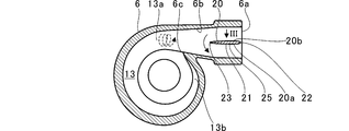
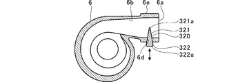
- FIG. 2 is a sectional view of the compressor housing and the valve.
- FIG. 3 is a view of the valve as viewed from an arrow III in FIG. 2.
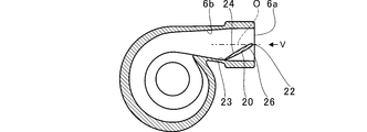
- FIG. 4 is a diagram for explaining a state in which the cross-sectional area of the discharge channel is minimum.
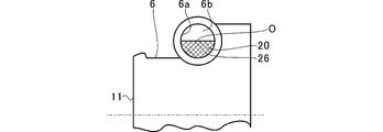
- FIG. 5 is a view on arrow V in FIG.
- FIG. 6 is a cross-sectional view of a portion corresponding to FIG. 4 in the first modification.
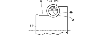
- FIG. 7 is a view taken in the direction of the arrow VII in FIG.
- FIG. 8 is a sectional view of a portion corresponding to a section taken along line VIII-VIII of FIG. 6 in the second modification.
- FIG. 9 is a view on arrow IX of FIG.
- FIG. 10 is a cross-sectional view of a portion corresponding to FIG. 4 in the third modification.
- FIG. 11 is a view of the valve as viewed from the discharge port side.
- FIG. 12 is a cross-sectional view of a portion corresponding to FIG. 4 in the fourth modification.
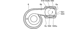
- FIG. 13 is a cross-sectional view of a portion corresponding to FIG. 4 in the fifth modification.
- FIG. 14 is a diagram for explaining a state at the minimum opening degree in the fifth modification.
- FIG. 15 is a diagram for explaining a state at the time of the maximum opening degree in the sixth modification.
- FIG. 16 is a diagram for explaining a state at the minimum opening degree in the sixth modification.
- FIG. 17 is a diagram for explaining a state at the maximum opening degree in the seventh modification.
- FIG. 11 is a view of the valve as viewed from the discharge port side.
- FIG. 12 is a cross-sectional view of a portion corresponding to FIG. 4 in the fourth modification.
- FIG. 18 is a diagram for explaining a state at the minimum opening degree in the seventh modification.
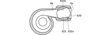
- FIG. 19 is a diagram for explaining a state at the time of the maximum opening degree in the eighth modification.
- FIG. 20 is a diagram for explaining a state at the minimum opening degree in the eighth modification.
- FIG. 1 is a schematic sectional view of the supercharger TC. 1 will be described as the left side of the supercharger TC. The direction of arrow R shown in FIG. 1 will be described as the right side of the supercharger TC.
- the supercharger TC includes a supercharger main body 1.
- the supercharger main body 1 includes a bearing housing 2.
- a turbine housing 4 is connected to the left side of the bearing housing 2 by a fastening bolt 3.
- a compressor housing 6 (housing) is connected to the right side of the bearing housing 2 by a fastening bolt 5.
- a bearing hole 2a is formed in the bearing housing 2.
- the bearing hole 2a penetrates the supercharger TC in the left-right direction.
- a bearing 7 is provided in the bearing hole 2a.
- FIG. 1 shows a full floating bearing as an example of the bearing 7. However, the bearing 7 may be another radial bearing such as a semi-floating bearing or a rolling bearing.
- the shaft 8 is rotatably supported by the bearing 7.
- a turbine impeller 9 is provided at the left end of the shaft 8.
- a turbine impeller 9 is rotatably housed in the turbine housing 4.
- a compressor impeller 10 is provided at the right end of the shaft 8.
- a compressor impeller 10 is rotatably housed in a housing space S formed in the compressor housing 6.
- An intake port 11 is formed in the compressor housing 6.
- the intake port 11 opens to the right of the supercharger TC.
- the intake port 11 is connected to an air cleaner (not shown).
- the diffuser flow path 12 is formed in a state where the bearing housing 2 and the compressor housing 6 are connected by the fastening bolts 5, the diffuser flow path 12 is formed.
- the diffuser channel 12 pressurizes air.
- the diffuser flow path 12 is formed in an annular shape from the inside to the outside in the radial direction of the shaft 8.
- the diffuser flow path 12 communicates with the intake port 11 via the compressor impeller 10 on the radially inner side.
- a compressor scroll channel 13 (scroll channel) is formed inside the compressor housing 6.
- the compressor scroll channel 13 is annular.
- the compressor scroll passage 13 is located, for example, radially outside the shaft 8 (compressor impeller 10) from the diffuser passage 12 (compressor impeller 10).
- the compressor scroll passage 13 communicates with an intake port of an engine (not shown).
- the compressor scroll channel 13 also communicates with the diffuser channel 12.
- the supercharger TC includes the compressor C.
- the compressor C includes a compressor housing 6, a compressor impeller 10, and a compressor scroll passage 13.
- An exhaust port 14 is formed in the turbine housing 4.
- the exhaust port 14 opens on the left side of the supercharger TC.
- the exhaust port 14 is connected to an exhaust gas purification device (not shown).
- the turbine housing 4 is provided with a flow path 15 and a turbine scroll flow path 16.
- the turbine scroll passage 16 is located radially outside the turbine impeller 9 relative to the turbine impeller 9.
- the flow path 15 is located between the turbine impeller 9 and the turbine scroll flow path 16.
- the turbine scroll passage 16 communicates with the gas inlet. Exhaust gas discharged from an exhaust manifold (not shown) of the engine is guided to the gas inlet.
- the turbine scroll flow path 16 also communicates with the flow path 15 described above.
- the exhaust gas guided from the gas inlet to the turbine scroll flow path 16 is guided to the exhaust port 14 via the flow path 15 and the space between the blades of the turbine impeller 9.
- the exhaust gas guided to the exhaust port 14 rotates the turbine impeller 9 during the flow of the exhaust gas.
- FIG. 2 is a cross-sectional view of the compressor housing 6 and the valve 20.
- a discharge port 6 a is formed in the compressor housing 6.
- the discharge port 6a opens outside the compressor housing 6.
- a discharge passage 6b is formed in the compressor housing 6.
- the discharge channel 6b extends in a substantially straight line from the compressor scroll channel 13 to the discharge port 6a.
- the discharge channel 6b connects (communicates) the downstream portion 13a of the compressor scroll channel 13 with the discharge port 6a.
- the downstream portion 13a and the upstream portion 13b of the compressor scroll flow path 13 are separated by a tongue 6c.
- the tongue 6c is located between the downstream 13a and the upstream 13b.
- the air flow path extends from the circumferential direction to the linear direction on the downstream side of the compressor scroll flow path 13.
- the downstream portion 13a is a portion of the compressor scroll flow path 13 that extends in a straight line direction.
- the boundary between the discharge passage 6b and the compressor scroll passage 13 is, for example, located at the tip of the tongue 6c.
- the discharge port 6a is closer to the discharge port 6a than the tongue 6c.
- the downstream side 13a of the compressor scroll flow path 13 is located on the side of the tongue 6c farther from the discharge port 6a than the tip.
- the boundary between the discharge flow path 6b and the compressor scroll flow path 13 may be located on a side farther from the discharge port 6a than the tip of the tongue 6c.
- Only one of the discharge passages 6b is provided as a passage communicating between the compressor scroll passage 13 and the discharge port 6a.
- the flow path connecting the compressor scroll flow path 13 and the discharge port 6a is not provided other than the discharge flow path 6b. All the air flowing out of the compressor scroll flow path 13 flows out of one discharge port 6a through the discharge flow path 6b.
- the air flowing out of the compressor scroll channel 13 merges after being separated.
- a loss due to the speed difference occurs. Since the compressor housing 6 has one discharge passage 6b and one discharge port 6a, loss due to a speed difference at the time of merging is avoided.
- FIG. 3 is a view of the valve 20 viewed from the arrow III in FIG.
- the right side is the discharge port 6a side
- the left side is the downstream portion 13a side of the compressor scroll flow path 13.
- a valve 20 is provided in the discharge channel 6b.
- the valve 20 has, for example, a shape obtained by halving an ellipse (hereinafter, referred to as a semi-elliptical shape). In this semi-elliptical shape, the length of the ellipse in the longitudinal direction is half. Further, the valve 20 has an approximately plate shape.
- the one end surface 20a of the valve 20 is more toward the compressor impeller 10 than the other end surface 20b.
- the other end surface 20b of the valve 20 is located on the back side.
- valve 20 is rotated in a direction indicated by an arrow in FIG. 2 by an actuator (not shown). In FIG. 2, the flow path cross-sectional area of the discharge flow path 6b is maximum. The valve 20 rotates around the end 22 closer to the discharge port 6a (downstream) than the center 21 in the longitudinal direction.
- FIG. 4 is a view for explaining a state in which the flow path cross-sectional area of the discharge flow path 6b is minimized.
- a minimum opening when the flow passage cross-sectional area of the discharge flow passage 6 b is minimum (hereinafter, referred to as a minimum opening), the upstream end (compressor scroll flow passage 13 side) of the valve 20.
- Reference numeral 23 contacts the inner wall surface of the discharge channel 6b. The end portion 23 of the valve 20 abuts on the inner wall surface of the discharge passage 6b on the compressor impeller 10 side.
- the valve 20 when the flow rate is small, the valve 20 has the minimum opening, so that the flow velocity of the air is increased and the stall of the air can be suppressed. Therefore, the operation area on the small flow rate side can be expanded. Since the valve 20 may be provided in the discharge channel 6b, the structure can be simplified. For example, in order to reduce the flow path cross-sectional area on the compressor scroll flow path 13 side, a plurality of valves are required. However, since the valve 20 is disposed on the discharge port 6a side with respect to the tongue 6c, the air flow path is united in the compressor scroll flow path 13. Therefore, the cross-sectional area of the air passage can be reduced by one valve 20.
- the valve 20 has the minimum opening, the end 22 on the discharge port 6a side is closer to the center O of the discharge flow path 6b than the end 23 on the compressor scroll flow path 13 side.
- the valve 20 has the inclined surface 24 at the time of the minimum opening.
- the other end surface 20b becomes the inclined surface 24.
- the opening degree is the minimum, the end of the inclined surface 24 closer to the discharge port 6a than the end of the compressor scroll flow path 13 (here, the same as the end 23) (here, the same as the end 22). Is closer to the center O of the discharge channel 6b. With the inclined surface 24, pressure loss is suppressed.
- the valve 20 has a curved portion 25.
- the curved portion 25 has a thickness from the end portion 23 on the compressor scroll passage 13 side to the end portion 22 on the discharge port 6a side when the flow passage cross-sectional area of the discharge flow passage 6b is maximum (hereinafter, referred to as a maximum opening). Increase.
- the curved portion 25 has, for example, a streamline shape. With the curved portion 25, pressure loss is suppressed.
- the bending portion 25 is provided on one end surface 20a and the other end surface 20b.
- FIG. 5 is a view on arrow V in FIG.
- the valve 20 is indicated by cross hatching, and the rotation axis of the compressor impeller 10 is indicated by a two-dot chain line.
- the valve 20 has a throttle section 26.
- the throttle section 26 When the throttle section 26 is at the minimum opening, the throttle section 26 has a compressor impeller 10 side (refer to FIG. 5) in a cross section of the discharge flow path 6b that is orthogonal to the direction in which the discharge flow path 6b extends. At the bottom).
- valve impeller 10 side (hereinafter, simply referred to as a flow path cross section) of the discharge flow path 6b at right angles to the extending direction of the discharge flow path 6b (hereinafter, simply referred to as flow path cross section).
- the whole is located on the lower side in FIG. 5).
- the throttle portion 26 is located closer to the compressor impeller 10 than the center O of the cross section of the discharge flow channel 6b.
- the throttle portion 26 may extend from the center O of the discharge passage 6b to a side (upper side in FIG. 5) apart from the compressor impeller 10.
- the throttle unit 26 is configured by the valve 20. In other words, the valve 20 forms the throttle unit 26.
- the flow velocity of the air flowing through the compressor scroll flow path 13 is higher on the radially outer side of the compressor impeller 10 than on the radially inner side when the air has a small flow rate.
- the flow velocity of the air flowing into the discharge passage 6b is faster on the side separated from the compressor impeller 10 than on the compressor impeller 10 side.
- the valve 20 is located on the compressor impeller 10 side, so that the flow of air having a higher flow rate is less likely to be hindered.
- the air flowing through the compressor scroll passage 13 forms a swirling flow (flow in the direction of the dashed arrow in FIG. 2).
- the swirling flow does not contribute to the flow velocity of the flow in the direction in which the discharge flow path 6b extends, resulting in a pressure loss.
- rectification is performed by the valve 20, and the swirling flow is suppressed. Therefore, pressure loss is suppressed.
- the velocity in the linear direction is increased by the valve 20, so that the proportion of the velocity component of the swirling flow in the flow velocity is reduced.
- the cross-sectional shape of the discharge channel 6b is approximately circular.
- the valve 20 is inclined with respect to the extending direction of the discharge channel 6b. Since the shape of the valve 20 is a semi-elliptical shape, the valve 20 can contact along the inner wall surface of the discharge flow path 6b at the minimum opening.
- FIG. 6 is a cross-sectional view of a portion corresponding to FIG. 4 in the first modification.
- FIG. 6 shows a case where the valve 120 has the minimum opening degree.
- the valve 120 is at the maximum opening degree, the same figure as FIG. 2 is obtained.
- the inclination direction of the valve 120 is different from the above-described embodiment.
- FIG. 7 is a view taken in the direction of the arrow VII in FIG.
- the rotation axis of the compressor impeller 10 is indicated by a two-dot chain line.
- the valve 120 when the valve 120 is at the minimum opening, the valve 120 is located on the side separated from the compressor impeller 10 in the flow path cross section of the discharge flow path 6 b.
- the throttle portion 126 of the valve 120 is located on the side of the discharge flow path 6b farther from the compressor impeller 10 than the center O of the flow path cross section of the discharge flow path 6b.
- the throttle portion 126 may extend from the center O of the discharge passage 6b to the compressor impeller 10 side.
- FIG. 8 is a cross-sectional view of a portion corresponding to a cross section taken along line VIII-VIII of FIG. 6 in the second modification. However, in FIG. 8, only the vicinity of the discharge port 6a is shown in cross section.
- FIG. 8 shows a direction rotated 90 degrees counterclockwise with respect to FIG.
- FIG. 9 is a view on arrow IX of FIG. 8 and 9, the rotation axis of the compressor impeller 10 is indicated by a two-dot chain line.
- the throttle section 226 in the rotation axis direction of the compressor impeller 10 vertical direction in FIG. It is located on one side (the upper side in FIG. 8, the intake port 11 side).
- the swirling flow is suppressed by the valves 120 and 220 when the opening degree is the minimum. Therefore, pressure loss is suppressed. Also at the maximum opening degree, since the speed in the linear direction (the extending direction of the discharge flow path 6b) is increased by the valves 120 and 220, the ratio of the velocity component of the swirling flow to the flow velocity is reduced.
- valves 120 and 220 also have the inclined surface 24 and the curved portion 25 in the first modification and the second modification. Therefore, pressure loss is suppressed.
- the cross-sectional shape of the discharge channel 6b is approximately circular.
- the valves 120 and 220 have the minimum opening, they are inclined with respect to the extending direction of the discharge flow path 6b. Since the shape of the valves 120 and 220 is a semi-elliptical shape, the valves 120 and 220 can contact along the inner wall surface of the discharge flow path 6b at the minimum opening.
- the inclined surface 24 is formed.
- the inclined surface 24 may not be formed. That is, when the valves 20, 120, and 220 have the minimum opening degree, the valves 20, 120, and 220 may be in a direction orthogonal to the extending direction of the discharge channel 6 b.
- the shapes of the valves 20, 120, and 220 may be semicircular. With the semicircular shape, the valves 20, 120, and 220 can contact along the inner wall surface of the discharge flow path 6b at the minimum opening degree.
- valves 20, 120, and 220 rotate around the end 22 closer to the discharge port 6a (downstream) than the center 21 in the longitudinal direction.
- valves 20, 120, and 220 may be rotated around the end 23 closer to the compressor scroll flow path 13 (upstream side) than the center 21 in the longitudinal direction.
- FIG. 10 is a cross-sectional view of a portion corresponding to FIG. 4 in the third modification.
- FIG. 11 is a view of the valve 320 as viewed from the discharge port 6a side. As shown in FIG. 11, the valve 320 has a main body 321 having a substantially semicircular shape. A protruding part 322 is provided in a middle part of the circumference of the main body part 321. The protruding portion 322 protrudes from the main body 321 outward in the radial direction of the main body 321.
- the thickness of the valve 320 decreases from the tip 322 a of the protrusion 322 toward the end 321 a of the main body 321 opposite to the protrusion 322.
- a through hole 6d is formed in the compressor housing 6.
- the through hole 6d penetrates the wall 6e forming the discharge flow path 6b in parallel with the flow path cross section of the discharge flow path 6b (in the radial direction of the discharge flow path 6b).
- the width of the through-hole 6d in the extending direction of the discharge channel 6b becomes smaller toward the discharge channel 6b (inner side).
- the valve 320 is inserted into the through hole 6d from outside.
- the main body 321 is located in the discharge channel 6b.
- the protrusion 322 is located inside the through hole 6 d and outside the compressor housing 6.
- valve 320 is moved in the through direction of the through hole 6d (in the radial direction of the discharge flow path 6b) by an actuator (not shown) as indicated by a double arrow in FIG.
- FIG. 10 shows a case where the valve 320 has the minimum opening degree.
- the discharge flow path 6b has the maximum opening.
- FIG. 12 is a cross-sectional view of a portion corresponding to FIG. 4 in the fourth modification.
- the valve 420 of the fourth modification is different from the valve 320 of the third modification in that the plate thickness is substantially constant.
- the width of the through hole 46d in the extending direction of the discharge flow path 6b is substantially constant.
- the shape of the valve 420 as viewed from the discharge port 6a is the same as that of the valve 320.
- Valve 420 operates similarly to valve 320.
- FIG. 13 is a sectional view of a portion corresponding to FIG. 4 in the fifth modification.
- the valve 520 of the fifth modified example is constituted by, for example, a ball valve.
- a casing 500 is provided on the outer periphery of the wall 6e forming the discharge flow path 6b.
- An actuator (not shown) is attached to the casing 500.
- the valve 520 has a main body 521 having a substantially spherical shape. A part of the casing 500 and a part of the wall 6e of the compressor housing 6 are cut out to form a fitting hole 510 into which the valve 520 is fitted. The valve 520 is rotatably supported by the fitting hole 510. The rotation axis of the valve 520 is, for example, parallel to the rotation axis of the compressor impeller 10.
- a communication hole 522 is formed in the main body 521.
- the communication hole 522 penetrates the main body 521.
- the communication hole 522 passes through the center of the main body 521.
- the opening on the discharge port 6a side (downstream side) of the communication hole 522 is the same as the cross-sectional shape of the discharge flow path 6b.
- the opening of the communication hole 522 on the compressor scroll flow path 13 side (upstream side) is larger than the flow path cross-sectional shape of the discharge flow path 6b.
- the communication hole 522 narrows from upstream to downstream.
- the inner wall surface 522a (inclined surface) of the communication hole 522 on the lower side (compressor impeller 10 side) in FIG. 13 is continuous with the inner wall surface of the discharge passage 6b.
- the upstream side of the inner wall surface 522b on the upper side (discharge channel 6b side) in FIG. 13 is separated outward from the inner wall surface of the discharge channel 6b.
- the downstream side of the upper inner wall surface 522b in FIG. 13 is continuous with the inner wall surface of the discharge channel 6b.
- FIG. 14 is a diagram for explaining a state at the time of the minimum opening in the fifth modification.
- the valve 520 is rotated by an actuator (not shown) in the direction of the arrow (counterclockwise) in FIG.
- the opening degree is the minimum
- the upper inner wall surface 522b of the communication hole 522 in FIG. 14 is located outside the inner wall surface of the discharge flow path 6b.
- the upstream side of the lower inner wall surface 522a (inclined surface) in FIG. 14 is separated outward from the inner wall surface of the discharge flow path 6b.
- the throttle portion 526 is formed in the valve 520.
- the throttle opening 526 is located on the compressor impeller 10 side (the lower side in FIG. 14) in the flow path cross section of the discharge flow path 6b (that is, the view as viewed from the discharge port 6a). Thereby, the flow path cross-sectional area of the discharge flow path 6b is reduced.
- the throttle portion 526 is located on the compressor impeller 10 side, so that the flow of the air having the higher flow rate is not easily disturbed.
- the throttle portion 526 is at the maximum opening degree, it is not located in the discharge channel 6b and does not hinder the flow.
- FIG. 15 is a view for explaining a state at the time of the maximum opening degree in the sixth modification.
- the inner wall surface 622b (inclined surface) on the upper side of the communication hole 622 in FIG. 15 is continuous with the inner wall surface of the discharge channel 6b.
- the upstream side of the lower inner wall surface 622a in FIG. 15 is separated outward from the inner wall surface of the discharge flow path 6b.
- the downstream side of the lower inner wall surface 622a in FIG. 15 is continuous with the inner wall surface of the discharge channel 6b.
- the wall of the valve 620 does not enter the discharge flow path 6b, and the flow is not hindered by the valve 620.
- FIG. 16 is a diagram for explaining a state at the minimum opening degree in the sixth modification.
- the valve 620 is rotated by an actuator (not shown) in the direction of the arrow (clockwise) in FIG.
- the lower inner wall surface 622a in FIG. 16 of the communication hole 622 is located outside the inner wall surface of the discharge flow path 6b.
- the upstream side of the upper inner wall surface 622b in FIG. 16 is separated outward from the inner wall surface of the discharge flow path 6b.
- the downstream side of the upper inner wall surface 622b in FIG. 16 projects inside the discharge flow path 6b.
- the throttle 626 is formed in the valve 620.
- the throttle portion 626 is located on the side (upper side in FIG. 14) separated from the compressor impeller 10 in the flow path cross section of the discharge flow path 6b (that is, the view from the discharge port 6a). Thereby, the flow path cross-sectional area of the discharge flow path 6b is reduced.
- the throttle portion 626 suppresses the swirling flow when the opening degree is the minimum.
- the throttle portion 626 has the maximum opening degree, it is not located in the discharge channel 6b and does not hinder the flow.
- FIG. 17 is a view for explaining a state at the time of the maximum opening degree in the seventh modification.
- the communication hole 722 of the valve 720 has a substantially constant cross-sectional shape from upstream to downstream.
- the cross-sectional shape of the communication hole 722 is substantially equal to the cross-sectional shape of the discharge channel 6b.
- FIG. 18 is a view for explaining a state at the time of the minimum opening in the seventh modification.
- the valve 720 is rotated by an actuator (not shown) in the direction of an arrow (counterclockwise) in FIG.
- the upstream side of the lower inner wall surface 722a (inclined surface) in FIG. 18 is located outside the discharge channel 6b, and the downstream side is inside the discharge channel 6b. Protrude.
- the end on the compressor scroll flow path 13 side of the lower inner wall surface 722a (inclined surface) in FIG. 6b it is located outside the inner wall surface on the upstream side (compressor scroll passage 13 side) of the end of the inner wall surface 722a.
- the downstream side of the upper inner wall surface 722b in FIG. 18 is located outside the discharge channel 6b, and the upstream side protrudes inside the discharge channel 6b.
- the valve 720 may be rotated in the opposite direction (clockwise) to the arrow in FIG. 17 to reach the minimum opening.
- the upstream side of the lower inner wall surface 722a in FIG. 18 protrudes inside the discharge channel 6b, and the downstream side is located outside the discharge channel 6b.
- the downstream side of the upper inner wall surface 722b in FIG. 18 protrudes inside the discharge channel 6b, and the upstream side is located outside the discharge channel 6b.
- FIG. 19 is a view for explaining a state at the time of the maximum opening in the eighth modification.
- the channel width in the discharge channel 6b, the channel width (inner diameter, channel cross-sectional area) increases toward the discharge port 6a.
- the flow path width in the communication hole 822 of the valve 820, the flow path width (inner diameter, flow path cross-sectional area) increases from upstream to downstream. At the maximum opening, the inner wall surface of the communication hole 822 is flush with the inner wall surface of the discharge channel 6b.
- FIG. 20 is a diagram for explaining a state at the minimum opening degree in the eighth modification.
- the valve 820 is rotated by an actuator (not shown) in the direction of an arrow (counterclockwise) in FIG.
- the upstream side is located outside the discharge channel 6b, and the downstream side is inside the discharge channel 6b in FIG. Protrude.
- the end of the lower inner wall surface 822a (inclined surface) on the compressor scroll flow channel 13 side in FIG. 6b it is located outside the inner wall surface on the upstream side (the compressor scroll flow path 13 side) of the end of the inner wall surface 822a.
- the downstream side of the upper inner wall surface 822b in FIG. 20 is located outside the discharge passage 6b, and the upstream side protrudes inside the discharge passage 6b.
- the valve 820 may be rotated in the opposite direction (clockwise) to the arrow in FIG.
- the upstream side of the lower inner wall surface 822a in FIG. 20 protrudes inside the discharge channel 6b, and the downstream side is located outside the discharge channel 6b.
- the downstream side of the upper inner wall surface 822b in FIG. 20 projects inside the discharge channel 6b, and the upstream side is located outside the discharge channel 6b.
- valves 520, 620, 720, 820 of the fifth, sixth, seventh, and eighth modifications described above the inner wall surfaces 522a, 622b, 722a of the communication holes 522, 622, 722, 822, 822b functions as the inclined surface 24. With the inclined surface 24, pressure loss is suppressed.
- the compressor C is incorporated in the supercharger TC.
- the compressor C may be incorporated in a device other than the supercharger TC, or may be a single unit.
- one end 23 of the valve 20 on the compressor scroll flow path 13 side contacts the inner wall surface of the discharge flow path 6b when the flow path cross-sectional area of the discharge flow path 6b is minimum.
- the one end 23 of the inclined surface 24 on the compressor scroll passage 13 side is connected to the one end 23 of the discharge passage 6b when the passage cross-sectional area of the discharge passage 6b is minimum. It may be located outside the inner wall surface on the upstream side (compressor scroll passage 13 side).
- the first modification, the fifth modification, the sixth modification, the seventh modification, and the eighth modification the case where the inclined surface 24 is provided has been described.
- the inclined surface 24 is not an essential component.
- the present disclosure can be used for compressors and superchargers.
Landscapes
- Engineering & Computer Science (AREA)
- Mechanical Engineering (AREA)
- General Engineering & Computer Science (AREA)
- Chemical & Material Sciences (AREA)
- Combustion & Propulsion (AREA)
- Supercharger (AREA)
Abstract
コンプレッサは、インペラが収容されたハウジングと、ハウジング内に形成され、インペラよりも、インペラの径方向外側に設けられるスクロール流路と、スクロール流路からハウジングに形成された吐出口6aまで延在する吐出流路6bと、吐出流路6bに設けられ、吐出流路6bの流路断面積が最小のとき、吐出流路6bのうち、吐出流路6bの延在方向に直交する流路断面において、インペラ側に位置する絞り部26を有するバルブ20と、を備える。
Description
本開示は、コンプレッサおよび過給機に関する。本出願は2018年9月19日に提出された日本特許出願第2018-174848号に基づく優先権の利益を主張するものであり、その内容は本出願に援用される。
過給機には、コンプレッサが設けられる。コンプレッサでは、少流量時の失速を抑制するため、エアバイパスバルブが設けられる。エアバイパスバルブは、コンプレッサハウジングに形成された戻り流路を開閉する。例えば、特許文献1には、複数に分割されたピースを組み付けることで戻り流路が形成されたコンプレッサハウジングが開示されている。
上記のように、コンプレッサハウジングに戻り流路を形成すると、構造が複雑化してしまう。
本開示の目的は、簡易な構成で少流量時の失速を抑制することが可能なコンプレッサおよび過給機を提供することである。
上記課題を解決するために、本開示の一態様に係るコンプレッサは、インペラが収容されたハウジングと、ハウジング内に形成され、インペラよりも、インペラの径方向外側に設けられるスクロール流路と、スクロール流路からハウジングに形成された吐出口まで延在する吐出流路と、吐出流路に設けられ、吐出流路の流路断面積が最小のとき、吐出流路のうち、吐出流路の延在方向に直交する流路断面において、インペラ側に位置する絞り部を有するバルブと、を備える。
バルブは、吐出流路の流路断面積が最小のとき、スクロール流路側の端部より、吐出口側の端部の方が、吐出流路の延在方向に直交する流路断面の中心に近い傾斜面を有してもよい。
傾斜面のスクロール流路側の端部は、吐出流路の流路断面積が最小のとき、吐出流路の内壁面よりも外側に位置してもよい。
バルブは、吐出流路の流路断面積が最大のとき、スクロール流路側の端部から吐出口側の端部に向って厚みが増加する湾曲部を有してもよい。
上記課題を解決するために、本開示の一態様に係る過給機は、上記コンプレッサを備える。
本開示によれば、簡易な構成で少流量時の失速を抑制することが可能となる。
以下に添付図面を参照しながら、本開示の一実施形態について詳細に説明する。実施形態に示す寸法、材料、その他具体的な数値等は、理解を容易とするための例示にすぎず、特に断る場合を除き、本開示を限定するものではない。なお、本明細書および図面において、実質的に同一の機能、構成を有する要素については、同一の符号を付することにより重複説明を省略する。また本開示に直接関係のない要素は図示を省略する。
図1は、過給機TCの概略断面図である。図1に示す矢印L方向を過給機TCの左側として説明する。図1に示す矢印R方向を過給機TCの右側として説明する。図1に示すように、過給機TCは、過給機本体1を備える。過給機本体1は、ベアリングハウジング2を備える。ベアリングハウジング2の左側には、締結ボルト3によってタービンハウジング4が連結される。ベアリングハウジング2の右側には、締結ボルト5によってコンプレッサハウジング6(ハウジング)が連結される。
ベアリングハウジング2には、軸受孔2aが形成されている。軸受孔2aは、過給機TCの左右方向に貫通する。軸受孔2aに軸受7が設けられる。図1では、軸受7の一例としてフルフローティング軸受を示す。ただし、軸受7は、セミフローティング軸受や転がり軸受など、他のラジアル軸受であってもよい。軸受7によって、シャフト8が回転自在に軸支されている。シャフト8の左端部にはタービンインペラ9が設けられる。タービンインペラ9がタービンハウジング4内に回転自在に収容されている。また、シャフト8の右端部にはコンプレッサインペラ10が設けられる。コンプレッサハウジング6内に形成された収容空間Sに、コンプレッサインペラ10が回転自在に収容されている。
コンプレッサハウジング6には、吸気口11が形成される。吸気口11は、過給機TCの右側に開口する。吸気口11は、不図示のエアクリーナに接続される。締結ボルト5によってベアリングハウジング2とコンプレッサハウジング6が連結された状態では、ディフューザ流路12が形成される。ディフューザ流路12は、空気を昇圧する。ディフューザ流路12は、シャフト8の径方向内側から外側に向けて環状に形成されている。ディフューザ流路12は、上記の径方向内側において、コンプレッサインペラ10を介して吸気口11に連通している。
コンプレッサハウジング6の内部には、コンプレッサスクロール流路13(スクロール流路)が形成される。コンプレッサスクロール流路13は環状である。コンプレッサスクロール流路13は、例えばディフューザ流路12(コンプレッサインペラ10)よりもシャフト8(コンプレッサインペラ10)の径方向外側に位置する。コンプレッサスクロール流路13は、不図示のエンジンの吸気口と連通する。コンプレッサスクロール流路13は、ディフューザ流路12にも連通している。コンプレッサインペラ10が回転すると、吸気口11からコンプレッサハウジング6内に空気が吸気される。吸気された空気は、コンプレッサインペラ10の翼間を流通する過程において、遠心力の作用により増速される。増速された空気は、ディフューザ流路12およびコンプレッサスクロール流路13で昇圧される。昇圧された空気は、後述する吐出口6a(図2参照)から流出し、エンジンの吸気口に導かれる。
このように、過給機TCは、コンプレッサCを備える。コンプレッサCは、コンプレッサハウジング6、コンプレッサインペラ10、コンプレッサスクロール流路13を含んで構成される。
タービンハウジング4には、排気口14が形成されている。排気口14は、過給機TCの左側に開口する。排気口14は、不図示の排気ガス浄化装置に接続される。タービンハウジング4には、流路15と、タービンスクロール流路16とが設けられている。タービンスクロール流路16は、タービンインペラ9よりもタービンインペラ9の径方向外側に位置する。流路15は、タービンインペラ9とタービンスクロール流路16との間に位置する。
タービンスクロール流路16は、ガス流入口と連通する。ガス流入口には、不図示のエンジンの排気マニホールドから排出される排気ガスが導かれる。タービンスクロール流路16は、上記の流路15にも連通している。ガス流入口からタービンスクロール流路16に導かれた排気ガスは、流路15およびタービンインペラ9の翼間を介して排気口14に導かれる。排気口14に導かれた排気ガスは、その流通過程においてタービンインペラ9を回転させる。
タービンインペラ9の回転力は、シャフト8を介してコンプレッサインペラ10に伝達される。空気は、コンプレッサインペラ10の回転力によって昇圧されて、エンジンの吸気口に導かれる。
図2は、コンプレッサハウジング6およびバルブ20の断面図である。図2に示すように、コンプレッサハウジング6には、吐出口6aが形成される。吐出口6aは、コンプレッサハウジング6の外部に開口する。コンプレッサハウジング6には、吐出流路6bが形成される。吐出流路6bは、コンプレッサスクロール流路13から吐出口6aまで、大凡直線状に延在する。吐出流路6bは、コンプレッサスクロール流路13の下流部13aと吐出口6aを接続(連通)する。
コンプレッサスクロール流路13の下流部13aと上流部13bは、舌部6cによって仕切られる。舌部6cは、下流部13aと上流部13bの間に位置する。空気の流路は、コンプレッサスクロール流路13の下流側において、延在方向が周方向から直線方向に変化している。下流部13aは、コンプレッサスクロール流路13のうち、直線方向に延在する部位とする。吐出流路6bとコンプレッサスクロール流路13との境界は、例えば、舌部6cの先端に位置するものとする。舌部6cより吐出口6a側が吐出流路6bである。舌部6cの先端より吐出口6aから離隔する側がコンプレッサスクロール流路13の下流部13aである。ただし、吐出流路6bとコンプレッサスクロール流路13との境界は、舌部6cの先端よりも吐出口6aから離隔する側に位置してもよい。
コンプレッサスクロール流路13と吐出口6aを連通する流路が、吐出流路6bの1つのみ設けられている。コンプレッサスクロール流路13と吐出口6aを連通する流路は、吐出流路6b以外に設けられていない。コンプレッサスクロール流路13から流出した空気は、すべて吐出流路6bを通って1つの吐出口6aから流出する。
例えば、複数の吐出流路6bや吐出口6aが設けられる場合、コンプレッサスクロール流路13から流出した空気は、分流された後に合流する。空気の合流時には、速度差による損失が生じてしまう。コンプレッサハウジング6では、吐出流路6b、吐出口6aを一つとしていることから、合流時の速度差による損失が回避される。
図3は、バルブ20の図2におけるIII矢視図である。図3中、右側が吐出口6a側、左側がコンプレッサスクロール流路13の下流部13a側である。図2に示すように、吐出流路6bには、バルブ20が設けられる。バルブ20は、図3に示すように、例えば、楕円を半分とした形状(以下、半楕円形状という)である。この半楕円形状では、楕円の長手方向の長さが半分となっている。また、バルブ20は、大凡板形状である。
図2に示す状態(後述する最大開度)のとき、バルブ20の一端面20aは、他端面20bよりもコンプレッサインペラ10側に向いている。コンプレッサインペラ10側から見たとき、バルブ20の他端面20bは、裏側に位置している。
バルブ20は、不図示のアクチュエータによって、図2中、矢印で示す方向に回転する。図2では、吐出流路6bの流路断面積が最大となっている。バルブ20は、長手方向の中心21よりも吐出口6a側(下流側)の端部22側を回転中心として回転する。
図4は、吐出流路6bの流路断面積が最小となっている状態を説明するための図である。図4に示すように、吐出流路6bの流路断面積が最小(以下、最小開度という)となっているとき、バルブ20のうち、上流側(コンプレッサスクロール流路13側)の端部23は、吐出流路6bの内壁面に当接する。バルブ20の端部23は、吐出流路6bのうち、コンプレッサインペラ10側の内壁面に当接する。
コンプレッサCでは、少流量時にバルブ20が最小開度となることで、空気の流速が上昇し、空気の失速を抑制することが可能となる。そのため、少流量側の運転領域の拡大が可能となる。吐出流路6bにバルブ20を設ければよいことから、構造の簡易化が可能となる。例えば、コンプレッサスクロール流路13側で流路断面積を絞ろうとすると、複数のバルブが必要となる。しかし、バルブ20は、舌部6cより吐出口6a側に配されることから、コンプレッサスクロール流路13内では、空気の流路が1つにまとまっている。そのため、空気の流路断面積を一つのバルブ20で絞ることが可能となる。
バルブ20は、最小開度のとき、コンプレッサスクロール流路13側の端部23よりも、吐出口6a側の端部22の方が、吐出流路6bの中心Oに近い。言い換えれば、バルブ20は、最小開度のときに傾斜面24を有する。バルブ20の最小開度では、他端面20bが傾斜面24となる。最小開度のとき、傾斜面24において、コンプレッサスクロール流路13側の端部(ここでは、端部23と同じ)よりも、吐出口6a側の端部(ここでは、端部22と同じ)の方が、吐出流路6bの中心Oに近い。傾斜面24を有することから、圧力損失が抑制される。
図2に示すように、バルブ20は、湾曲部25を有する。湾曲部25は、吐出流路6bの流路断面積が最大(以下、最大開度という)のとき、コンプレッサスクロール流路13側の端部23から吐出口6a側の端部22に向って厚みが増加する。湾曲部25は、例えば、流線形状である。湾曲部25を有することから、圧力損失が抑制される。湾曲部25は、一端面20aおよび他端面20bに設けられる。
図5は、図4のV矢視図である。図5では、バルブ20をクロスハッチングで示し、コンプレッサインペラ10の回転軸を二点鎖線で示す。バルブ20は、絞り部26を有する。絞り部26は、最小開度のとき、吐出流路6bのうち、吐出流路6bの延在方向に直交する流路断面(以下、単に流路断面という)において、コンプレッサインペラ10側(図5において下側)に位置する。言い換えれば、バルブ20は、最小開度のとき、吐出流路6bのうち、吐出流路6bの延在方向に直交する流路断面(以下、単に流路断面という)において、コンプレッサインペラ10側(図5において下側)に全体が位置する。絞り部26は、吐出流路6bの流路断面の中心Oよりもコンプレッサインペラ10側に位置する。ただし、絞り部26は、吐出流路6bの中心Oよりも、コンプレッサインペラ10から離隔する側(図5において上側)まで延在していてもよい。絞り部26は、バルブ20によって構成される。言い換えれば、バルブ20は、絞り部26を構成する。
コンプレッサスクロール流路13を流れる空気の流速は、空気が小流量の場合、コンプレッサインペラ10の径方向外側の方が径方向内側よりも速い。吐出流路6bに流入した空気の流速は、コンプレッサインペラ10から離隔する側の方が、コンプレッサインペラ10側よりも速い。最小開度のとき、バルブ20がコンプレッサインペラ10側に位置することから、流速が速い方の空気の流れが阻害され難い。
コンプレッサスクロール流路13(吐出流路6b)を流れる空気は、旋回流(図2の破線の矢印の向きの流れ)を形成している。旋回流は、吐出流路6bの延在方向の流れの流速に寄与せず、圧力損失となる。最大開度のとき、バルブ20によって整流がなされ、旋回流が抑制される。そのため、圧力損失が抑制される。また、最小開度のときも、バルブ20によって直線方向(吐出流路6bの延在方向)の速度が増加することから、流速のうち、旋回流の速度成分の占める割合が小さくなる。
図5を見てわかるように、吐出流路6bの流路断面形状は、大凡円形である。バルブ20は、最小開度のとき、吐出流路6bの延在方向に対して傾斜する。バルブ20の形状が半楕円形状となっているため、最小開度のとき、バルブ20が吐出流路6bの内壁面に沿って当接可能となる。
図6は、第1変形例における図4に対応する部位の断面図である。図6では、バルブ120が最小開度のときを示す。バルブ120が最大開度のときは、図2と同じ図となる。図6に示すように、第1変形例では、上述した実施形態に対して、バルブ120の傾斜の向きが異なる。
図7は、図6のVII矢視図である。図7において、コンプレッサインペラ10の回転軸を二点鎖線で示す。図6、図7を見てわかるように、バルブ120は、最小開度のとき、吐出流路6bの流路断面において、コンプレッサインペラ10から離隔する側に位置する。バルブ120の絞り部126は、吐出流路6bのうち、吐出流路6bの流路断面の中心Oよりもコンプレッサインペラ10から離隔する側に位置する。ただし、絞り部126は、吐出流路6bの中心Oよりも、コンプレッサインペラ10側まで延在していてもよい。
図8は、第2変形例における図6のVIII-VIII線断面に対応する部位の断面図である。ただし、図8では、吐出口6a近傍のみを断面で示す。図8は、図6に対して、反時計回りに90度回転した向きとなっている。図9は、図8のIX矢視図である。図8、図9において、コンプレッサインペラ10の回転軸を二点鎖線で示す。図8、図9に示すように、バルブ220の絞り部226は、最小開度のとき、吐出流路6bの流路断面において、コンプレッサインペラ10の回転軸方向(図8中、上下方向)の一方側(図8中、上側、吸気口11側)に位置する。
また、絞り部226は、最小開度のとき、吐出流路6bのうち、流路断面において、コンプレッサインペラ10の回転軸方向の他方側(図8中、下側、吸気口11から離隔する側)に位置してもよい。
第1変形例、第2変形例では、最小開度のとき、バルブ120、220によって旋回流が抑制される。そのため、圧力損失が抑制される。また、最大開度のときも、バルブ120、220によって直線方向(吐出流路6bの延在方向)の速度が増加することから、流速のうち、旋回流の速度成分の占める割合が小さくなる。
上述した実施形態と同様、第1変形例、第2変形例においても、バルブ120、220は、傾斜面24、および、湾曲部25を有する。そのため、圧力損失が抑制される。吐出流路6bの流路断面形状は、大凡円形である。バルブ120、220は、最小開度のとき、吐出流路6bの延在方向に対して傾斜する。バルブ120、220の形状が半楕円形状となっているため、最小開度のとき、バルブ120、220が吐出流路6bの内壁面に沿って当接可能となる。
上述した実施形態および第1変形例、第2変形例では、傾斜面24が形成されている。しかし、傾斜面24は形成されなくてもよい。すなわち、バルブ20、120、220は、最小開度のとき、吐出流路6bの延在方向に直交する向きとなってもよい。この場合、バルブ20、120、220の形状は、半円形状であってもよい。半円形状であると、最小開度のとき、バルブ20、120、220が吐出流路6bの内壁面に沿って当接可能となる。
上述した実施形態および第1変形例、第2変形例では、バルブ20、120、220は、長手方向の中心21よりも吐出口6a側(下流側)の端部22側を回転中心として回転する。しかし、バルブ20、120、220は、長手方向の中心21よりもコンプレッサスクロール流路13側(上流側)の端部23側を回転中心として回転してもよい。
図10は、第3変形例における図4に対応する部位の断面図である。図11は、バルブ320を吐出口6a側から見た図である。図11に示すように、バルブ320は、大凡半円形状の本体部321を有する。本体部321のうち、円周の中間部分には、突出部322が設けられる。突出部322は、本体部321から本体部321の径方向外側に突出する。
図10に示すように、バルブ320の板厚は、突出部322の先端322aから、本体部321のうち、突出部322と反対側の端部321aに向かって薄くなる。コンプレッサハウジング6には、貫通孔6dが形成される。貫通孔6dは、吐出流路6bを形成する壁部6eを、吐出流路6bの流路断面に平行に(吐出流路6bの径方向に)貫通する。貫通孔6dのうち、吐出流路6bの延在方向の幅は、吐出流路6b側(内側)ほど小さくなる。
バルブ320は、貫通孔6dに外側から挿通される。本体部321は、吐出流路6bに位置する。突出部322は、貫通孔6dの内部およびコンプレッサハウジング6の外側に位置する。
バルブ320は、図10中、両矢印で示すように、不図示のアクチュエータにより、貫通孔6dの貫通方向(吐出流路6bの径方向)に移動する。図10では、バルブ320が最小開度のときを示す。バルブ320が、吐出流路6bに突出しない位置まで、図10中、下側に移動することで、吐出流路6bは最大開度となる。
図12は、第4変形例における図4に対応する部位の断面図である。第4変形例のバルブ420は、板厚が大凡一定である点で、第3変形例のバルブ320と異なる。貫通孔46dのうち、吐出流路6bの延在方向の幅は、大凡一定である。バルブ420を吐出口6aから見た形状は、バルブ320と同じである。バルブ420は、バルブ320と同様に動作する。
図13は、第5変形例における図4に対応する部位の断面図である。第5変形例のバルブ520は、例えば、ボール弁で構成される。コンプレッサハウジング6のうち、吐出流路6bを形成する壁部6eの外周には、ケーシング500が設けられる。ケーシング500には、不図示のアクチュエータが取り付けられる。
バルブ520は、大凡球形状の本体部521を有する。ケーシング500およびコンプレッサハウジング6の壁部6eの一部が切り欠かれ、バルブ520が嵌め込まれる嵌合穴510が形成される。バルブ520は、嵌合穴510によって回転可能に支持される。バルブ520の回転軸は、例えば、コンプレッサインペラ10の回転軸と平行である。
本体部521には、連通孔522が形成される。連通孔522は、本体部521を貫通する。連通孔522は、本体部521の中心を通る。連通孔522のうち、吐出口6a側(下流側)の開口は、吐出流路6bの流路断面形状と同じである。連通孔522のうち、コンプレッサスクロール流路13側(上流側)の開口は、吐出流路6bの流路断面形状よりも大きい。連通孔522は、上流から下流に向かって狭くなっている。
最大開度のとき、連通孔522のうち、図13中、下側(コンプレッサインペラ10側)の内壁面522a(傾斜面)は、吐出流路6bの内壁面に連続する。連通孔522において、図13中、上側(吐出流路6b側)の内壁面522bのうち、上流側は、吐出流路6bの内壁面から外側に離隔する。連通孔522において、図13中、上側の内壁面522bのうち、下流側は、吐出流路6bの内壁面に連続する。このとき、吐出流路6bには、バルブ520の壁部(内壁面522a(傾斜面))が進入せず、バルブ520によって流れが阻害されない。
図14は、第5変形例における最小開度のときの状態を説明するための図である。バルブ520は、不図示のアクチュエータによって、図13中、矢印の向き(反時計回り)に回転し、最小開度となる。最小開度のとき、連通孔522のうち、図14中、上側の内壁面522bは、吐出流路6bの内壁面の外側に位置する。連通孔522において、図14中、下側の内壁面522a(傾斜面)のうち、上流側は、吐出流路6bの内壁面から外側に離隔する。連通孔522において、図14中、下側の内壁面522a(傾斜面)のうち、コンプレッサスクロール流路13側の端部は、吐出流路6bの流路断面積が最小のとき、吐出流路6bのうち、内壁面522aの端部よりも上流側(コンプレッサスクロール流路13側)の内壁面よりも外側に位置する。連通孔522において、図14中、下側の内壁面522aのうち、下流側は、吐出流路6bの内側に突出する。そのため、吐出流路6bの流路断面積が絞られる。
言い換えると、バルブ520には、絞り部526が形成される。絞り部526は、最小開度のとき、吐出流路6bの流路断面(すなわち、吐出口6aから見た図)において、コンプレッサインペラ10側(図14中、下側)に位置する。これにより、吐出流路6bの流路断面積が絞られる。上述した実施形態と同様、最小開度のとき、絞り部526がコンプレッサインペラ10側に位置することから、流速が速い方の空気の流れが阻害され難い。絞り部526は、最大開度のとき、吐出流路6b内に位置せず、流れを阻害しない。
図15は、第6変形例における最大開度のときの状態を説明するための図である。最大開度のとき、連通孔622のうち、図15中、上側の内壁面622b(傾斜面)は、吐出流路6bの内壁面に連続する。連通孔622において、図15中、下側の内壁面622aのうち、上流側は、吐出流路6bの内壁面から外側に離隔する。連通孔622において、図15中、下側の内壁面622aのうち、下流側は、吐出流路6bの内壁面に連続する。このとき、吐出流路6bには、バルブ620の壁部が進入せず、バルブ620によって流れが阻害されない。
図16は、第6変形例における最小開度のときの状態を説明するための図である。バルブ620は、不図示のアクチュエータによって、図15中、矢印の向き(時計回り)に回転し、最小開度となる。最小開度のとき、連通孔622のうち、図16中、下側の内壁面622aは、吐出流路6bの内壁面の外側に位置する。連通孔622において、図16中、上側の内壁面622bのうち、上流側は、吐出流路6bの内壁面から外側に離隔する。連通孔622において、図16中、上側の内壁面622bのうち、下流側は、吐出流路6bの内側に突出する。
言い換えると、バルブ620には、絞り部626が形成される。絞り部626は、最小開度のとき、吐出流路6bの流路断面(すなわち、吐出口6aから見た図)において、コンプレッサインペラ10から離隔する側(図14中、上側)に位置する。これにより、吐出流路6bの流路断面積が絞られる。上述した第1変形例と同様、絞り部626は、最小開度のとき、旋回流を抑制する。絞り部626は、最大開度のとき、吐出流路6b内に位置せず、流れを阻害しない。
図17は、第7変形例における最大開度のときの状態を説明するための図である。バルブ720の連通孔722は、上流から下流まで、流路断面形状が大凡一定である。連通孔722の流路断面形状は、吐出流路6bの流路断面形状と大凡等しい。
図18は、第7変形例における最小開度のときの状態を説明するための図である。バルブ720は、不図示のアクチュエータによって、図17中、矢印の向き(反時計回り)に回転し、最小開度となる。この場合、連通孔722において、図18中、下側の内壁面722a(傾斜面)のうち、上流側は、吐出流路6bの外側に位置し、下流側は、吐出流路6bの内側に突出する。連通孔722において、図18中、下側の内壁面722a(傾斜面)のうち、コンプレッサスクロール流路13側の端部は、吐出流路6bの流路断面積が最小のとき、吐出流路6bのうち、内壁面722aの端部よりも上流側(コンプレッサスクロール流路13側)の内壁面よりも外側に位置する。連通孔722において、図18中、上側の内壁面722bのうち、下流側は、吐出流路6bの外側に位置し、上流側は吐出流路6bの内側に突出する。
バルブ720は、図17中、矢印と逆向き(時計回り)に回転して最小開度となってもよい。この場合、連通孔722において、図18中、下側の内壁面722aのうち、上流側は、吐出流路6bの内側に突出し、下流側は、吐出流路6bの外側に位置する。連通孔722において、図18中、上側の内壁面722bのうち、下流側は、吐出流路6bの内側に突出し、上流側は吐出流路6bの外側に位置する。
図19は、第8変形例における最大開度のときの状態を説明するための図である。吐出流路6bは、吐出口6aに向かって流路幅(内径、流路断面積)が拡大する。バルブ820の連通孔822は、上流から下流に向かって、流路幅(内径、流路断面積)が拡大する。最大開度のとき、連通孔822の内壁面は、吐出流路6bの内壁面と面一となる。
図20は、第8変形例における最小開度のときの状態を説明するための図である。バルブ820は、不図示のアクチュエータによって、図19中、矢印の向き(反時計回り)に回転し、最小開度となる。この場合、連通孔822において、図20中、下側の内壁面822a(傾斜面)のうち、上流側は、吐出流路6bの外側に位置し、下流側は、吐出流路6bの内側に突出する。連通孔822において、図20中、下側の内壁面822a(傾斜面)のうち、コンプレッサスクロール流路13側の端部は、吐出流路6bの流路断面積が最小のとき、吐出流路6bのうち、内壁面822aの上記端部よりも上流側(コンプレッサスクロール流路13側)の内壁面よりも外側に位置する。連通孔822において、図20中、上側の内壁面822bのうち、下流側は、吐出流路6bの外側に位置し、上流側は吐出流路6bの内側に突出する。
バルブ820は、図19中、矢印と逆向き(時計回り)に回転して最小開度となってもよい。この場合、連通孔822において、図20中、下側の内壁面822aのうち、上流側は、吐出流路6bの内側に突出し、下流側は、吐出流路6bの外側に位置する。連通孔822において、図20中、上側の内壁面822bのうち、下流側は、吐出流路6bの内側に突出し、上流側は吐出流路6bの外側に位置する。
上述した第5変形例、第6変形例、第7変形例、第8変形例のバルブ520、620、720、820において、連通孔522、622、722、822の内壁面522a、622b、722a、822bは、傾斜面24として機能する。傾斜面24を有することから、圧力損失が抑制される。
以上、添付図面を参照しながら本開示の一実施形態について説明したが、本開示はかかる実施形態に限定されないことは言うまでもない。当業者であれば、特許請求の範囲に記載された範疇において、各種の変更例または修正例に想到し得ることは明らかであり、それらについても当然に本開示の技術的範囲に属するものと了解される。
例えば、上述した実施形態および変形例では、コンプレッサCが過給機TCに組み込まれる場合について説明した。しかし、コンプレッサCは、過給機TC以外の装置に組み込まれてもよいし、単体であってもよい。
上述した実施形態では、バルブ20のうち、コンプレッサスクロール流路13側の一端部23は、吐出流路6bの流路断面積が最小のとき、吐出流路6bの内壁面に当接する。ただし、上述した実施形態において、傾斜面24のうち、コンプレッサスクロール流路13側の一端部23は、吐出流路6bの流路断面積が最小のとき、吐出流路6bのうち、一端部23よりも上流側(コンプレッサスクロール流路13側)の内壁面よりも外側に位置してもよい。
上述した実施形態、第1変形例、第5変形例、第6変形例、第7変形例、第8変形例では、傾斜面24が設けられる場合について説明した。しかし、傾斜面24は必須の構成ではない。
上述した実施形態、第1変形例、第2変形例では、湾曲部25が設けられる場合について説明した。しかし、湾曲部25は必須の構成ではない。
上述した第5変形例、第6変形例、第7変形例、第8変形例では、バルブ520、620、720、820の回転軸は、コンプレッサインペラ10の回転軸と大凡平行である場合について説明した。しかし、バルブ520、620、720、820の回転軸は、コンプレッサインペラ10の回転軸に対して交差してもよい。
本開示は、コンプレッサおよび過給機に利用することができる。
6:コンプレッサハウジング(ハウジング) 6a:吐出口 6b:吐出流路 13:コンプレッサスクロール流路(スクロール流路) 20、120、220、320、420、520、620、720、820:バルブ 21:中心 22、23、321a:端部 24:傾斜面 25:湾曲部 26、126、226、526、626:絞り部 522a、622b、722a、822a:内壁面(傾斜面) C:コンプレッサ TC:過給機
Claims (5)
- インペラが収容されたハウジングと、
前記ハウジング内に形成され、前記インペラよりも、前記インペラの径方向外側に設けられるスクロール流路と、
前記スクロール流路から前記ハウジングに形成された吐出口まで延在する吐出流路と、
前記吐出流路に設けられ、前記吐出流路の流路断面積が最小のとき、前記吐出流路のうち、前記吐出流路の延在方向に直交する流路断面において、前記インペラ側に位置する絞り部を有するバルブと、
を備えるコンプレッサ。 - 前記バルブは、前記吐出流路の流路断面積が最小のとき、前記スクロール流路側の端部より、前記吐出口側の端部の方が、前記吐出流路の延在方向に直交する流路断面の中心に近い傾斜面を有する請求項1に記載のコンプレッサ。
- 前記傾斜面の前記スクロール流路側の端部は、前記吐出流路の流路断面積が最小のとき、前記吐出流路の内壁面よりも外側に位置する請求項2に記載のコンプレッサ。
- 前記バルブは、前記吐出流路の流路断面積が最大のとき、前記スクロール流路側の端部から前記吐出口側の端部に向って厚みが増加する湾曲部を有する請求項1から3のいずれか1項に記載のコンプレッサ。
- 請求項1から4のいずれか1項に記載の前記コンプレッサを備える過給機。
Applications Claiming Priority (2)
| Application Number | Priority Date | Filing Date | Title |
|---|---|---|---|
| JP2018174848 | 2018-09-19 | ||
| JP2018-174848 | 2018-09-19 |
Publications (1)
| Publication Number | Publication Date |
|---|---|
| WO2020059631A1 true WO2020059631A1 (ja) | 2020-03-26 |
Family
ID=69888470
Family Applications (1)
| Application Number | Title | Priority Date | Filing Date |
|---|---|---|---|
| PCT/JP2019/035892 Ceased WO2020059631A1 (ja) | 2018-09-19 | 2019-09-12 | コンプレッサおよび過給機 |
Country Status (1)
| Country | Link |
|---|---|
| WO (1) | WO2020059631A1 (ja) |
Citations (3)
| Publication number | Priority date | Publication date | Assignee | Title |
|---|---|---|---|---|
| US3176704A (en) * | 1961-11-20 | 1965-04-06 | Universal Oil Prod Co | Carburetor throttle valve |
| JPS6128799A (ja) * | 1984-07-19 | 1986-02-08 | Nissan Motor Co Ltd | 遠心圧縮機 |
| JP2005155496A (ja) * | 2003-11-26 | 2005-06-16 | Aisin Seiki Co Ltd | コンプレッサ |
-
2019
- 2019-09-12 WO PCT/JP2019/035892 patent/WO2020059631A1/ja not_active Ceased
Patent Citations (3)
| Publication number | Priority date | Publication date | Assignee | Title |
|---|---|---|---|---|
| US3176704A (en) * | 1961-11-20 | 1965-04-06 | Universal Oil Prod Co | Carburetor throttle valve |
| JPS6128799A (ja) * | 1984-07-19 | 1986-02-08 | Nissan Motor Co Ltd | 遠心圧縮機 |
| JP2005155496A (ja) * | 2003-11-26 | 2005-06-16 | Aisin Seiki Co Ltd | コンプレッサ |
Similar Documents
| Publication | Publication Date | Title |
|---|---|---|
| JP5369723B2 (ja) | 遠心圧縮機 | |
| US20180231053A1 (en) | Bearing structure and turbocharger | |
| JP6234600B2 (ja) | タービン | |
| CN105378293A (zh) | 离心压缩机以及增压器 | |
| WO2016035329A1 (ja) | ターボチャージャの排気タービン | |
| WO2018146753A1 (ja) | 遠心圧縮機、ターボチャージャ | |
| US11686244B2 (en) | Variable-capacity turbocharger | |
| CN110520630B (zh) | 离心压缩机 | |
| JP6633761B2 (ja) | タービン及びターボチャージャ | |
| US11047256B2 (en) | Variable nozzle unit and turbocharger | |
| JP7635844B2 (ja) | タービン及び過給機 | |
| US12152602B2 (en) | Centrifugal compressor | |
| US20190107052A1 (en) | Turbocharger | |
| JP7196994B2 (ja) | 可変容量型過給機 | |
| JP2012002140A (ja) | タービン及び過給機 | |
| US11946480B2 (en) | Centrifugal compressor | |
| JP5974501B2 (ja) | ターボ機械の可変静翼機構 | |
| US20200040899A1 (en) | Centrifugal compressor | |
| JP7395002B2 (ja) | タービン及びターボチャージャ | |
| US20220003151A1 (en) | Turbine and turbocharger | |
| JPWO2019004228A1 (ja) | 遠心圧縮機 | |
| JP6980028B2 (ja) | ディフューザ及びターボチャージャー | |
| US20230160321A1 (en) | Bearing and turbocharger | |
| JP7782713B2 (ja) | 回転装置 | |
| US12385505B2 (en) | Centrifugal compressor |
Legal Events
| Date | Code | Title | Description |
|---|---|---|---|
| 121 | Ep: the epo has been informed by wipo that ep was designated in this application |
Ref document number: 19861510 Country of ref document: EP Kind code of ref document: A1 |
|
| NENP | Non-entry into the national phase |
Ref country code: DE |
|
| 122 | Ep: pct application non-entry in european phase |
Ref document number: 19861510 Country of ref document: EP Kind code of ref document: A1 |
|
| NENP | Non-entry into the national phase |
Ref country code: JP |