WO2020059529A1 - 画像処理装置、画像処理方法及びプログラム、並びに携帯端末装置 - Google Patents
画像処理装置、画像処理方法及びプログラム、並びに携帯端末装置 Download PDFInfo
- Publication number
- WO2020059529A1 WO2020059529A1 PCT/JP2019/035058 JP2019035058W WO2020059529A1 WO 2020059529 A1 WO2020059529 A1 WO 2020059529A1 JP 2019035058 W JP2019035058 W JP 2019035058W WO 2020059529 A1 WO2020059529 A1 WO 2020059529A1
- Authority
- WO
- WIPO (PCT)
- Prior art keywords
- image
- region
- unit
- image processing
- area
- Prior art date
- Legal status (The legal status is an assumption and is not a legal conclusion. Google has not performed a legal analysis and makes no representation as to the accuracy of the status listed.)
- Ceased
Links
Images






Classifications
-
- G—PHYSICS
- G06—COMPUTING OR CALCULATING; COUNTING
- G06T—IMAGE DATA PROCESSING OR GENERATION, IN GENERAL
- G06T7/00—Image analysis
- G06T7/10—Segmentation; Edge detection
- G06T7/11—Region-based segmentation
-
- G—PHYSICS
- G06—COMPUTING OR CALCULATING; COUNTING
- G06F—ELECTRIC DIGITAL DATA PROCESSING
- G06F16/00—Information retrieval; Database structures therefor; File system structures therefor
- G06F16/50—Information retrieval; Database structures therefor; File system structures therefor of still image data
-
- G—PHYSICS
- G06—COMPUTING OR CALCULATING; COUNTING
- G06F—ELECTRIC DIGITAL DATA PROCESSING
- G06F16/00—Information retrieval; Database structures therefor; File system structures therefor
- G06F16/50—Information retrieval; Database structures therefor; File system structures therefor of still image data
- G06F16/55—Clustering; Classification
-
- G—PHYSICS
- G06—COMPUTING OR CALCULATING; COUNTING
- G06T—IMAGE DATA PROCESSING OR GENERATION, IN GENERAL
- G06T7/00—Image analysis
-
- G—PHYSICS
- G06—COMPUTING OR CALCULATING; COUNTING
- G06T—IMAGE DATA PROCESSING OR GENERATION, IN GENERAL
- G06T7/00—Image analysis
- G06T7/10—Segmentation; Edge detection
- G06T7/12—Edge-based segmentation
-
- G—PHYSICS
- G06—COMPUTING OR CALCULATING; COUNTING
- G06T—IMAGE DATA PROCESSING OR GENERATION, IN GENERAL
- G06T7/00—Image analysis
- G06T7/10—Segmentation; Edge detection
- G06T7/149—Segmentation; Edge detection involving deformable models, e.g. active contour models
-
- G—PHYSICS
- G06—COMPUTING OR CALCULATING; COUNTING
- G06V—IMAGE OR VIDEO RECOGNITION OR UNDERSTANDING
- G06V10/00—Arrangements for image or video recognition or understanding
- G06V10/20—Image preprocessing
- G06V10/25—Determination of region of interest [ROI] or a volume of interest [VOI]
-
- G—PHYSICS
- G06—COMPUTING OR CALCULATING; COUNTING
- G06V—IMAGE OR VIDEO RECOGNITION OR UNDERSTANDING
- G06V10/00—Arrangements for image or video recognition or understanding
- G06V10/70—Arrangements for image or video recognition or understanding using pattern recognition or machine learning
- G06V10/74—Image or video pattern matching; Proximity measures in feature spaces
- G06V10/75—Organisation of the matching processes, e.g. simultaneous or sequential comparisons of image or video features; Coarse-fine approaches, e.g. multi-scale approaches; using context analysis; Selection of dictionaries
- G06V10/751—Comparing pixel values or logical combinations thereof, or feature values having positional relevance, e.g. template matching
-
- G—PHYSICS
- G06—COMPUTING OR CALCULATING; COUNTING
- G06V—IMAGE OR VIDEO RECOGNITION OR UNDERSTANDING
- G06V10/00—Arrangements for image or video recognition or understanding
- G06V10/70—Arrangements for image or video recognition or understanding using pattern recognition or machine learning
- G06V10/762—Arrangements for image or video recognition or understanding using pattern recognition or machine learning using clustering, e.g. of similar faces in social networks
- G06V10/763—Non-hierarchical techniques, e.g. based on statistics of modelling distributions
-
- G—PHYSICS
- G06—COMPUTING OR CALCULATING; COUNTING
- G06N—COMPUTING ARRANGEMENTS BASED ON SPECIFIC COMPUTATIONAL MODELS
- G06N20/00—Machine learning
-
- G—PHYSICS
- G06—COMPUTING OR CALCULATING; COUNTING
- G06T—IMAGE DATA PROCESSING OR GENERATION, IN GENERAL
- G06T2207/00—Indexing scheme for image analysis or image enhancement
- G06T2207/20—Special algorithmic details
- G06T2207/20081—Training; Learning
Definitions
- the present invention relates to an image processing device, an image processing method and a program, and a mobile terminal device, and particularly to a technique for extracting a region of interest from an image.
- Non-Patent Document 1 discloses a technique for performing segmentation by assigning meaningful labels to all pixels in an image using AI (Artificial Intelligence). ing.
- Non-Patent Document 2 discloses a technique in which a user designates a selection range by dragging in a single stroke.
- Patent Literature 1 discloses a technique for selecting a partial area from one image for image processing such as enlargement and trimming.
- Non-Patent Document 1 has a problem that it cannot deal with data not used at the time of creating the AI.
- the technique disclosed in Non-Patent Document 2 has a problem that many operations are required when selecting a fine region or when correcting an erroneous selection.
- the output partial area is limited to a rectangular area, and a non-rectangular area cannot be extracted.
- the present invention has been made in view of such circumstances, and it is an object of the present invention to provide an image processing apparatus, an image processing method, a program, and a portable terminal apparatus that more accurately extract a user's region of interest from an image with few operations.
- an image processing apparatus includes an image acquisition unit that acquires an image, an area division unit that divides the acquired image into a plurality of areas, and at least one of a plurality of divided areas.
- a selecting unit for selecting two regions an analyzing unit for analyzing a relationship between the selected region and a region other than the selected region, and belonging to the same group as the region selected from the analyzed relationships
- an output unit that outputs a grouping candidate for the area.
- the acquired image is divided into a plurality of regions, at least one of the plurality of divided regions is selected, and a relationship between the selected region and a region other than the selected region is selected.
- Analysis and outputs the grouping candidates of the region belonging to the same group as the region selected from the analyzed relationship, so that the user's region of interest is extracted from the image as a grouping candidate more accurately with fewer operations. can do.
- the output unit preferably outputs a plurality of grouping candidates. As a result, the user's region of interest can be more accurately extracted.
- the selection unit selects at least one region based on a user input. Further, the selection unit may select at least one area based on the learned machine learning model. Thereby, the region of interest can be appropriately extracted.
- the correction processing is preferably a geometric conversion processing.
- the region of interest subjected to the geometric transformation processing can be extracted.
- the correction process is preferably a contour line correction process. As a result, it is possible to extract a region of interest whose outline has been corrected.
- the region dividing unit divides the image into a plurality of regions by performing clustering based on the pixel information.
- the image can be appropriately divided into a plurality of regions.
- the analysis unit analyzes a relationship between the selected region and a region adjacent to the selected region. Thereby, appropriate grouping candidates can be output.
- the analysis unit analyzes the similarity between the selected area and an area other than the selected area. Thereby, appropriate grouping candidates can be output.
- the analysis unit analyzes the relationship based on the learned machine learning model. Thereby, appropriate grouping candidates can be output.
- the image forming apparatus further includes a limiting unit that limits a range from the acquired image, and the region dividing unit divides the image in the limited range into a plurality of regions. Thereby, a region of interest can be extracted from a necessary range in the image, and the amount of calculation can be reduced.
- one mode of a mobile terminal device includes the image processing device described above, an imaging lens, an imaging element that captures an optical image formed by the imaging lens, and a display unit.
- the image acquisition unit acquires image data output from the image sensor as an image
- the output unit is a mobile terminal device that displays grouping candidates on a display unit.
- one mode of an image processing method includes an image acquiring step of acquiring an image, an area dividing step of dividing the acquired image into a plurality of areas, and at least one of the plurality of divided areas.
- the user's region of interest can be more accurately extracted from the image with a small number of operations.
- a program for causing a computer to execute the above-described image processing method is also included in the present embodiment.
- a user's region of interest can be more accurately extracted from an image with a small number of operations.
- FIG. 1 is a front perspective view of the tablet PC.
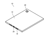
- FIG. 2 is a rear perspective view of the tablet PC.
- FIG. 3 is a block diagram illustrating a system configuration of the tablet PC.
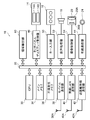
- FIG. 4 is a block diagram illustrating a system configuration of the area extracting unit.
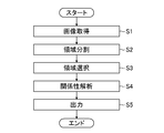
- FIG. 5 is a flowchart showing the image processing method.
- FIG. 6 is a diagram illustrating an example of an image in a range limited by the range limiting unit among the images acquired by the image acquiring unit.
- FIG. 7 is a diagram illustrating an example of a plurality of regions divided by the region dividing unit.
- FIG. 8 is an example of an analysis result of the analysis unit.
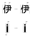
- FIG. 9 is a diagram illustrating an example in which a character is divided into a plurality of regions.
- FIG. 10 is a diagram illustrating an example in which each area forms one character.
- FIG. 11 is a diagram illustrating an example in which each area forms one object.
- FIG. 12 is a diagram
- the image processing apparatus can accurately extract a user's region of interest from an image with a small number of operations. For example, an area of a logo or a signboard that is of interest to the user can be extracted from an image in which a logo or a signboard or the like is captured. Further, it is possible to extract a face paint pattern area from an image in which a face painted face is applied.
- FIG. 1 is a front perspective view of a tablet-type computer terminal 10 (hereinafter, referred to as a tablet PC 10), which is an example of a portable terminal device to which the image processing apparatus according to the present embodiment is applied.
- 2 is a rear perspective view.
- the tablet PC 10 includes a flat casing 12 having a rectangular outline.
- the housing 12 includes a touch panel display 14, operation buttons 16, a speaker 18, a built-in camera 20, and an external connection terminal 24.
- FIG. 3 is a block diagram showing a system configuration of the tablet PC 10.
- the tablet PC 10 includes a CPU (Central Processing Unit) 30 that controls the overall operation of the tablet PC 10.
- the CPU 30 communicates with the main memory 34, the non-volatile memory 36, the mobile communication unit 38, the wireless LAN (Local Area Network) communication unit 40, the short-range wireless communication unit 42, and the wired communication via the system bus 32.
- the unit 44, the touch panel display control unit 46, the key input unit 50, the audio processing unit 52, the imaging processing unit 54, and the area extracting unit 60 are connected.
- the CPU 30 reads an OS (Operating System) stored in the non-volatile memory 36, an application program operating on the OS, fixed data, and the like, expands the data in the main memory 34, and executes the operation program. It functions as a control unit that controls the entire operation.
- OS Operating System
- the main memory 34 is constituted by, for example, a RAM (Random Access Memory) and functions as a work memory of the CPU 30.
- the non-volatile memory 36 is formed of, for example, a flash EEPROM (Electrically Erasable Programmable Read Only Memory), and stores an OS, application programs, and various standard data.
- the nonvolatile memory 36 functions as a storage unit of the tablet PC 10 and stores various data.
- the mobile communication unit 38 communicates with the nearest wireless base station (not shown) via the antenna 38A by the fourth generation mobile communication system (4G: 4th @ Generation) or the 5th generation mobile communication system (5G: 5th @ Generation). Send and receive data.
- fourth generation mobile communication system 4G: 4th @ Generation
- 5th generation mobile communication system 5G: 5th @ Generation
- the wireless LAN communication unit 40 communicates with an external device capable of wireless LAN access point or wireless LAN communication via an antenna 40A, for example, IEEE (Institute of Electrical and Electronics Electronics) 802.11a / b / g / n standard.
- IEEE Institute of Electrical and Electronics Electronics 802.11a / b / g / n standard.
- the wireless LAN communication according to the wireless LAN communication standard such as this is performed.
- the short-range wireless communication unit 42 communicates with another Bluetooth (registered trademark) standard device in a class 2 (within a radius of about 10 m), for example, via the antenna 42A.
- the wired communication unit 44 performs communication according to a predetermined communication standard with an external device connected via a cable (not shown) via the external connection terminal 24.
- the touch panel display 14 (an example of a display unit) includes a display unit 14A such as a color LCD (Liquid Crystal Display) panel for displaying an image and the like, and a touch panel unit such as a transparent electrode that is arranged on the front of the color LCD panel and receives a touch input. 14B.
- a display unit 14A such as a color LCD (Liquid Crystal Display) panel for displaying an image and the like
- a touch panel unit such as a transparent electrode that is arranged on the front of the color LCD panel and receives a touch input. 14B.
- the touch panel portion 14B is made of, for example, glass or plastic, and has a light-transmitting substrate body, a light-transmitting position detecting electrode provided in a planar shape on the substrate body, and a light-transmitting position detecting electrode.
- 4 is a capacitive touch panel including an insulating layer provided.
- the touch panel unit 14B is arranged on the front surface of the display unit 14A, and generates and outputs two-dimensional position coordinate information corresponding to a user's touch operation.
- the touch panel display control unit 46 controls the touch panel display 14.
- the touch panel display control unit 46 associates the coordinates of the image displayed on the display unit 14A with the coordinates of the touch operation on the touch panel unit 14B.
- the display on the display unit 14A and the touch operation on the touch panel unit 14B are simply referred to as the display on the touch panel display 14 and the operation on the touch panel display 14.
- the key input unit 50 is configured by a drive circuit that drives the plurality of operation buttons 16.
- the audio processing unit 52 converts digital audio data supplied via the system bus 32 into an analog signal.
- the analog audio signal is reproduced and output from the speaker 18.
- the built-in camera 20 includes an imaging lens 20A and an imaging device 20B.
- the imaging lens 20A forms an optical image of the incident subject.
- the image sensor 20B captures the formed optical image and outputs an analog image signal.
- the imaging processing unit 54 digitizes an analog image signal output from the built-in camera 20 (imaging element 20B), performs required signal processing, and outputs the digital image signal.
- the region extracting unit 60 is an image processing device that extracts a region of interest of a user from an image displayed on the touch panel display 14.
- FIG. 4 is a block diagram showing a system configuration of the area extracting unit 60.
- the region extracting unit 60 includes an image acquiring unit 62, a region dividing unit 66, a selecting unit 68, an analyzing unit 70, and an output unit 72.
- the touch panel display control unit 46 acquires a captured image (an example of image data output from the image sensor) captured by the built-in camera 20, for example, and causes the touch panel display 14 to display the captured image.
- the touch panel display control unit 46 may acquire the image read from the non-volatile memory 36 and display the image on the touch panel display 14, or the mobile communication unit 38, the wireless LAN communication unit 40, the short-range wireless communication unit 42, and the wired
- the image acquired via the communication unit 44 may be displayed on the touch panel display 14.
- the image acquisition unit 62 acquires the images displayed on the touch panel display 14.
- the image acquired by the image acquisition unit 62 may be a moving image.
- the image acquisition section 62 includes a range limiting section 64.
- the range limiting unit 64 limits the range of the image acquired by the image acquiring unit 62 according to, for example, a user input.
- the user input to the range limiting unit 64 is performed by a user performing a touch operation such as surrounding a desired range of an image using the touch panel display 14.
- the area dividing unit 66 divides the image acquired by the image acquiring unit 62 into a plurality of areas as preprocessing.
- the region dividing unit 66 divides the range limited by the range limiting unit 64 in the image acquired by the image acquiring unit 62 into a plurality of regions. This makes it possible to reduce the number of calculations for extracting the region of interest as compared to the case where the entire image is divided into a plurality of regions.
- the region dividing unit 66 divides an image into a plurality of regions by performing clustering based on, for example, pixel information.
- the area dividing unit 66 may divide the area into a plurality of areas by applying, for example, SLIC (Simple Linear Iterative Clustering).
- SLIC Simple Linear Iterative Clustering
- the SLIC is an algorithm that takes an image as input, and outputs a division into superpixels that capture pixels that are close in terms of distance and color as a unit. By calculating a superpixel as preprocessing for image recognition, the amount of information of the image is reduced, and it becomes easier to apply another image recognition algorithm.
- the selection unit 68 selects at least one of the plurality of divided areas.
- the selection unit 68 selects an area based on, for example, a user input.
- the user input to the selection unit 68 is performed by the user performing a touch operation such as tracing a desired area of the image using the touch panel display 14 or surrounding the desired area. By causing the user to select a region, a region of interest can be appropriately extracted.
- the selection unit 68 may select an area based on a learned machine learning model.
- the division result of the region division unit 66 is input to the learned machine learning model, the general user's region of interest is estimated in the learned machine learning model, and the estimated region of interest is output as the output of the selection unit 68. I just need.
- the number of user operations can be reduced, and the region of interest can be appropriately extracted.
- the learned machine learning model may additionally learn a region of interest selected by the user as learning data.
- the analysis unit 70 analyzes a relationship (identity or similarity) between the region selected by the selection unit 68 and a region other than the selected region.
- the analysis performed by the analysis unit 70 includes analyzing the similarity of each region from the similarity of the pixel values such as the color and luminance of the pixels included in each region. Note that the maximum similarity means that they are the same area. By analyzing the similarity, an appropriate grouping candidate can be output.
- the analysis performed by the analysis unit 70 is not limited to the analysis of the similarity. For example, it includes analyzing whether or not each area has a meaningful relationship as an object, a character, or a character string when combined. In this case, the analysis unit 70 preferably uses a learned machine learning model.
- the output unit 72 outputs a grouping candidate of an area belonging to the same group as the area selected by the selection unit 68 based on the relationship analyzed by the analysis unit 70.
- the output unit 72 causes the touch panel display 14 to display, for example, a grouping candidate having the highest degree of certainty via the touch panel display control unit 46.
- the display may be switched to different grouping candidates according to a user operation on the touch panel display 14.
- the output unit 72 may sort the plurality of grouping candidates according to the degree of certainty and display the list on the touch panel display 14.
- the output unit 72 may apply a learned machine learning model. It is also possible to simultaneously learn the learned machine learning models of the selecting unit 68, the analyzing unit 70, and the output unit 72.
- the learned machine learning model described here may be subjected to further additional learning by applying a different learning data set. That is, the learned machine learning model is not limited to a model for which learning has been completed, but includes a model that can be updated later.
- the output unit 72 includes a correction processing unit 74.
- the correction processing unit 74 performs a correction process on the grouping candidates.
- the correction process is a geometric transformation process such as distortion correction. Further, the correction processing may be an outline correction processing.
- the output unit 72 outputs the grouping candidates subjected to the correction processing by the correction processing unit 74. As described above, the output unit 72 can output a grouping candidate whose geometric transformation processing or contour has been corrected.
- FIG. 5 is a flowchart illustrating an image processing method by the tablet PC 10. As shown in FIG. 5, the image processing method includes an image acquisition step (step S1), an area division step (step S2), an area selection step (step S3), a relationship analysis step (step S4), and an output Step (step S5).
- step S ⁇ b> 1 the image acquisition unit 62 acquires an image displayed on the touch panel display 14.
- range limiting section 64 limits the range surrounded by the touch operation of touch panel display 14 by the user, from the images displayed on touch panel display 14.
- FIG. 6 is a diagram illustrating an example of a range limited by the range limiting unit 64 in the image acquired by the image acquiring unit 62. As shown in FIG. 6, the region R1 is a region in a range limited by the range limiting unit 64.
- step S2 the area dividing section 66 divides the image acquired by the image acquiring section 62 into a plurality of areas.
- the region dividing unit 66 divides the range limited by the range limiting unit 64 in the image acquired by the image acquiring unit 62 into a plurality of regions.
- FIG. 7 is a diagram showing an example of a plurality of areas divided by the area dividing unit 66. As shown in FIG. 7, the region R1 shown in FIG. 6 is divided into a plurality of regions R11 to R19.
- step S3 the selection unit 68 selects at least one of the plurality of divided areas.
- the touch panel display control unit 46 displays on the touch panel display 14 a message prompting the user to select an area.
- the user surrounds a desired area by a touch operation on the touch panel display 14.
- the selection unit 68 selects an area surrounded by a touch operation by the user from among the plurality of areas displayed on the touch panel display 14. For example, it is assumed that the region R13 is selected from the plurality of regions R11 to R19 shown in FIG.
- step S4 the analysis unit 70 analyzes the relationship between the area selected in step S3 and an area other than the selected area.
- the analysis unit 70 analyzes, for example, the similarity between the selected region R13 and the pixel values such as the color and luminance of the pixels included in each of the regions R11, R12, and R14 to R19 other than the region R13. I do.
- the relationship between the distances between the regions may be analyzed.
- the distance here may be a distance in a pixel unit or a distance in actual size conversion. It is considered that the closer the distances are, the higher the relationship is.
- the analysis unit 70 may analyze the relationship between the selected region R13 and the region R14 adjacent to the region R13. Here, when it is determined that the relationship between the region R13 and the region R14 is high, the analysis unit 70 analyzes the relationship between the region R13 and the region R15 further adjacent to the region R14. As described above, when the adjacent region is a region having a high relationship, the analysis unit 70 may sequentially expand the adjacent regions to analyze the relationship. By analyzing the relationship between adjacent regions, appropriate grouping candidates can be output.
- step S5 the output unit 72 outputs a grouping candidate of an area belonging to the same group as the area selected in step S3 based on the relationship analyzed in step S4.
- the correction processing unit 74 may perform a geometric conversion process or a contour correction process.
- the output unit 72 sorts the two grouping candidates according to the certainty factor and causes the touch panel display 14 to display them.
- FIG. 8 is an example of a grouping candidate based on the analysis result of the analysis unit 70.
- the region R13 selected in step S3 is grouped as the same region R22 as the regions R12, R14, and R15. Further, here, the region R11 is independently grouped with the region R21, and the regions R16 to R19 are grouped as the region R23.
- the region R13 selected in step S3 is grouped as the same region R32 as the regions R12 and R14 to R19. Further, the region R11 is independently grouped as a region R31.
- the output unit 72 causes the touch panel display 14 to display the grouping candidates G1 and the grouping candidates G2. Only the region R22 and the region R32 may be displayed as grouping candidates for the region R13 selected in step S3.
- the user selects a desired grouping candidate from the plurality of grouping candidates displayed on the touch panel display 14 by a touch operation on the touch panel display 14, and determines the selected grouping candidate as the user's region of interest.
- the output unit 72 displays the determined region of interest on the touch panel display 14 and stores it in the non-volatile memory 36, and ends the processing of this flowchart.
- the output unit 72 may store all the grouping candidates in the nonvolatile memory 36.
- the region of interest of the user can be more accurately extracted.
- the analysis unit 70 analyzes the similarity of the pixel values such as the color and luminance of the pixel as the relationship, but the relationship analyzed by the analysis unit 70 is not limited to the similarity.
- the relationship analyzed by the analysis unit 70 includes, when each region forms a part of a character, whether or not the relationship forms a character by combining them.
- FIG. 9 is a diagram showing an example in which a character is divided into a plurality of areas.
- the analysis unit 70 analyzes the relationship between “i” in the region R41 and “youn” in the region R42, and determines that the relationship forms one character “I”. Therefore, the output unit 72 groups and outputs the region R41 and the region R42 as one region R43.
- the analysis unit 70 analyzes the relationship between “•” in the region R44 and “
- the relationship analyzed by the analysis unit 70 is a relationship corresponding to any one of a single word, an abbreviation, a trade name, and the like when each area constitutes one character or a plurality of characters and is combined. Including whether there is.
- FIG. 10 is a diagram showing an example in which each area forms one character.
- the analysis unit 70 analyzes the relationship between “J” in the region R51 and “R” in the region R52, and forms a relationship that forms “JR” which is (part of) one trade name. Is determined to be. Therefore, the output unit 72 groups and outputs the region R51 and the region R52 as one region R53.
- the analysis unit 70 sets the regions R12 to R19 shown in FIG. 7 in the regions consisting of the characters “F”, “U”, “J”, “I”, “F”, “I”, “L”, and “M”.
- the output unit 72 groups and outputs these areas as “FUJI” and “FILM”.
- the analysis unit 70 further analyzes the relationship between the region forming the word “FUJI” and the region forming the word “FILM”, and determines that the relationship forms the trade name “FUJIFILM”. You can also.
- the output unit 72 groups and outputs these areas as “FUJIFILM”.
- the relationship analyzed by the analysis unit 70 includes whether or not each region is a relationship that forms an object when combined.
- FIG. 11 is a diagram showing an example in which each area forms one object.
- the analysis unit 70 includes a region R61 and a region R62 of a metal portion, a region R63 of a resin portion, a region R64 of a plastic portion, a region R65 and a region R66 of a glass portion, a region R67 and a region R68 of a rubber portion.
- the output unit 72 groups and outputs the regions R61 to R68 as one region R70.
- the analysis unit 70 has analyzed the relationship between the selected selected region and the region adjacent to the selected region, but the region for analyzing the relationship is not limited to the adjacent region.
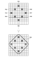
- FIG. 12 is a diagram illustrating an example of a range limited by the range limiting unit 64, and is a diagram illustrating an example in which non-adjacent regions configure one object.
- the image is divided into regions in a grid pattern, and regions R81 to R88 having high pixel value similarity relations are present in a dispersed manner without being adjacent to each other.
- the analysis unit 70 analyzes the relationship not only for the region adjacent to the selected region R81 but also for the nearby region.
- the nearby area refers to an area existing within a certain distance range.
- the analysis unit 70 determines that among the regions near the region R81, the relationship between the region R81, the region R82, and the region R88 is high. In this case, the analysis unit 70 analyzes the relationship between the region R81 and the region near the region R82 and the region R88. As a result, the analysis unit 70 determines that the relationship between the region R81 and the regions R83 and R87 is high. As described above, when the nearby region is a region having a high relationship, the analysis unit 70 sequentially expands the nearby region and analyzes the relationship, so that the output unit 72 outputs the data as shown in FIG. , Regions R81 to R88 can be grouped and output as one region R90.
- the output unit 72 may set only the regions R81 to R88 as the region R90, or may set the region R90 including a region existing between the regions other than the regions R81 to R88. When only the regions R81 to R88 are set as the region R90, a region existing between the regions may be treated as a transparent region.
- the user when a user wants to extract a region of interest from an image, the user can extract the region of interest more accurately with a small number of operations.
- a tablet-type computer terminal has been described as an example of a mobile terminal device to which the image processing apparatus is applied.
- the image processing method described above may be configured as a program for causing a computer to realize each step, and may be configured as a non-temporary recording medium such as a CD-ROM (Compact Disk-Read Only Memory) storing the program. It is possible.
- a CD-ROM Compact Disk-Read Only Memory
- the hardware structure of the processing unit (processing unit) that executes various processes of the area extraction unit 60 is the following various processors.
- Various processors include a CPU (Central Processing Unit), which is a general-purpose processor that executes software (programs) and functions as various processing units, a GPU (Graphics Processing Unit), a processor specialized in image processing, Dedicated to execute specific processing such as Programmable Logic Device (PLD), which is a processor whose circuit configuration can be changed after manufacturing FPGA (Field Programmable Gate Array), etc., and ASIC (Application Specific Integrated Circuit).
- PLD Programmable Logic Device
- FPGA Field Programmable Gate Array
- ASIC Application Specific Integrated Circuit
- One processing unit may be configured by one of these various processors, or may be configured by two or more processors of the same type or different types (for example, a plurality of FPGAs, a combination of a CPU and an FPGA, or a combination of a CPU and a CPU). (Combination of GPUs). Further, a plurality of processing units may be configured by one processor. As an example of configuring a plurality of processing units with one processor, first, as represented by a computer such as a server and a client, one processor is configured by a combination of one or more CPUs and software. There is a form in which a processor functions as a plurality of processing units.
- SoC system-on-chip
- a form using a processor that realizes the functions of the entire system including a plurality of processing units with one integrated circuit (IC) chip is used.
- IC integrated circuit
- the various processing units are configured using one or more various processors as a hardware structure.
- circuitry circuitry in which circuit elements such as semiconductor elements are combined.
- Tablet computer terminal (tablet PC) 12 ... housing 14 ... touch panel display 14A ... display section 14B ... touch panel section 16 ... operation buttons 18 ... speaker 20 ... built-in camera 20A ... imaging lens 20B ... imaging element 24 ... external connection terminal 32 ... system bus 34 ... main memory 36 ...
- Non-volatile memory 38 Mobile communication unit 38A Antenna 40 Wireless LAN communication unit 40A Antenna 42 Short-range wireless communication unit 42A Antenna 44 Wired communication unit 46 Touch panel display control unit 50 Key input unit 52 Voice processing Unit 54 imaging processing unit 60 area extracting unit 62 image acquiring unit 64 range limiting unit 66 area dividing unit 68 selecting unit 70 analyzing unit 72 output unit 74 correction processing units G1 and G2 grouping candidate R1 ... Regions R11 to R19 ... R21 to R23 ... Regions R31 and R32 ... R Each step of 1 ⁇ R46 ... region R51 ⁇ R53 ... region R61 ⁇ R68 ... region R70 ... region R81 ⁇ R88 ... region R90 ... areas S1 ⁇ S5 ... image processing method
Landscapes
- Engineering & Computer Science (AREA)
- Theoretical Computer Science (AREA)
- Physics & Mathematics (AREA)
- General Physics & Mathematics (AREA)
- Computer Vision & Pattern Recognition (AREA)
- Software Systems (AREA)
- Multimedia (AREA)
- Databases & Information Systems (AREA)
- Artificial Intelligence (AREA)
- Medical Informatics (AREA)
- Computing Systems (AREA)
- Evolutionary Computation (AREA)
- Health & Medical Sciences (AREA)
- General Health & Medical Sciences (AREA)
- General Engineering & Computer Science (AREA)
- Data Mining & Analysis (AREA)
- Probability & Statistics with Applications (AREA)
- Mathematical Physics (AREA)
- Image Analysis (AREA)
- User Interface Of Digital Computer (AREA)
- Image Processing (AREA)
Abstract
Description
本実施形態に係る画像処理装置は、少ない操作で正確に画像からユーザの関心領域を抽出することができる。例えば、ロゴ又は看板等が写った画像から、ユーザの興味のあるロゴ又は看板の領域を抽出することができる。また、フェイスペイントが施された顔が写った画像から、フェイスペイントの図柄の領域を抽出することができる。
図5は、タブレットPC10による画像処理方法を示すフローチャートである。図5に示すように、画像処理方法は、画像取得工程(ステップS1)と、領域分割工程(ステップS2)と、領域選択工程(ステップS3)と、関係性解析工程(ステップS4)と、出力工程(ステップS5)と、を含んでいる。
ここでは画像処理装置を適用した携帯端末装置の一例としてタブレット型コンピュータ端末について説明したが、スマートフォン、携帯電話機等の移動体通信端末、ノート型のパーソナルコンピュータ等に適用することも可能である。
12…筐体
14…タッチパネルディスプレイ
14A…ディスプレイ部
14B…タッチパネル部
16…操作ボタン
18…スピーカ
20…内蔵カメラ
20A…撮像レンズ
20B…撮像素子
24…外部接続端子
32…システムバス
34…メインメモリ
36…不揮発性メモリ
38…モバイル通信部
38A…アンテナ
40…無線LAN通信部
40A…アンテナ
42…近距離無線通信部
42A…アンテナ
44…有線通信部
46…タッチパネルディスプレイ制御部
50…キー入力部
52…音声処理部
54…撮像処理部
60…領域抽出部
62…画像取得部
64…範囲限定部
66…領域分割部
68…選択部
70…解析部
72…出力部
74…補正処理部
G1,G2…グルーピング候補
R1…領域
R11~R19…領域
R21~R23…領域
R31,R32…領域
R41~R46…領域
R51~R53…領域
R61~R68…領域
R70…領域
R81~R88…領域
R90…領域
S1~S5…画像処理方法の各ステップ
Claims (16)
- 画像を取得する画像取得部と、
前記取得した画像を複数の領域に分割する領域分割部と、
前記分割された複数の領域のうち少なくとも1つの領域を選択する選択部と、
前記選択された領域と前記選択された領域以外の領域との間の関係性を解析する解析部と、
前記解析された関係性から前記選択された領域と同一のグループに属する領域のグルーピング候補を出力する出力部と、
を備えた画像処理装置。 - 前記出力部は、複数のグルーピング候補を出力する請求項1に記載の画像処理装置。
- 前記選択部は、ユーザ入力に基づいて前記少なくとも1つの領域を選択する請求項1又は2に記載の画像処理装置。
- 前記選択部は、学習済み機械学習モデルに基づいて前記少なくとも1つの領域を選択する請求項1又は2に記載の画像処理装置。
- 前記グルーピング候補に対して補正処理を行う処理部を備える請求項1から4のいずれか1項に記載の画像処理装置。
- 前記補正処理は幾何変換処理である請求項5に記載の画像処理装置。
- 前記補正処理は輪郭線の修正処理である請求項5に記載の画像処理装置。
- 前記領域分割部は、画素情報に基づいてクラスタリングすることで前記複数の領域に分割する請求項1から7のいずれか1項に記載の画像処理装置。
- 前記解析部は、前記選択された領域と前記選択された領域に隣接する領域との間の関係性を解析する請求項1から8のいずれか1項に記載の画像処理装置。
- 前記解析部は、前記選択された領域と前記選択された領域以外の領域との間の類似度を解析する請求項1から9のいずれか1項に記載の画像処理装置。
- 前記解析部は、学習済み機械学習モデルに基づいて前記関係性を解析する請求項1から10のいずれか1項に記載の画像処理装置。
- 前記取得した画像から範囲を限定する限定部を備え、
前記領域分割部は、前記限定された範囲の画像を前記複数の領域に分割する請求項1から11のいずれか1項に記載の画像処理装置。 - 請求項1から12のいずれか1項に記載の画像処理装置と、
撮像レンズと、
前記撮像レンズにより結像される光学像を撮像する撮像素子と、
表示部と、
を備え、
前記画像取得部は、前記撮像素子から出力される画像データを画像として取得し、
前記出力部は、前記グルーピング候補を前記表示部に表示させる携帯端末装置。 - 画像を取得する画像取得工程と、
前記取得した画像を複数の領域に分割する領域分割工程と、
前記分割された複数の領域のうち少なくとも1つの領域を選択する選択工程と、
前記選択された領域と前記選択された領域以外の領域との間の関係性を解析する解析工程と、
前記解析された関係性から前記選択された領域と同一のグループに属する領域のグルーピング候補を出力する出力工程と、
を備えた画像処理方法。 - 請求項14に記載の画像処理方法をコンピュータに実行させるためのプログラム。
- 非一時的かつコンピュータ読取可能な記録媒体であって、前記記録媒体に格納された指令がコンピュータによって読み取られた場合に請求項15に記載のプログラムをコンピュータに実行させる記録媒体。
Priority Applications (3)
| Application Number | Priority Date | Filing Date | Title |
|---|---|---|---|
| CN201980061179.2A CN112740273B (zh) | 2018-09-20 | 2019-09-05 | 图像处理装置、方法、便携式终端装置及记录介质 |
| JP2020548322A JP7170051B2 (ja) | 2018-09-20 | 2019-09-05 | 画像処理装置、画像処理方法及びプログラム、並びに携帯端末装置 |
| US17/204,784 US11983877B2 (en) | 2018-09-20 | 2021-03-17 | Image processing device, image processing method, program, and portable terminal device |
Applications Claiming Priority (2)
| Application Number | Priority Date | Filing Date | Title |
|---|---|---|---|
| JP2018175767 | 2018-09-20 | ||
| JP2018-175767 | 2018-09-20 |
Related Child Applications (1)
| Application Number | Title | Priority Date | Filing Date |
|---|---|---|---|
| US17/204,784 Continuation US11983877B2 (en) | 2018-09-20 | 2021-03-17 | Image processing device, image processing method, program, and portable terminal device |
Publications (1)
| Publication Number | Publication Date |
|---|---|
| WO2020059529A1 true WO2020059529A1 (ja) | 2020-03-26 |
Family
ID=69887280
Family Applications (1)
| Application Number | Title | Priority Date | Filing Date |
|---|---|---|---|
| PCT/JP2019/035058 Ceased WO2020059529A1 (ja) | 2018-09-20 | 2019-09-05 | 画像処理装置、画像処理方法及びプログラム、並びに携帯端末装置 |
Country Status (4)
| Country | Link |
|---|---|
| US (1) | US11983877B2 (ja) |
| JP (1) | JP7170051B2 (ja) |
| CN (1) | CN112740273B (ja) |
| WO (1) | WO2020059529A1 (ja) |
Cited By (1)
| Publication number | Priority date | Publication date | Assignee | Title |
|---|---|---|---|---|
| JP2024106986A (ja) * | 2023-01-27 | 2024-08-08 | 国立研究開発法人農業・食品産業技術総合研究機構 | 物体検出モデルの学習装置、学習方法、学習データの生成方法、学習プログラム及び記録媒体 |
Citations (4)
| Publication number | Priority date | Publication date | Assignee | Title |
|---|---|---|---|---|
| JP2001297303A (ja) * | 2000-02-09 | 2001-10-26 | Ricoh Co Ltd | 文書画像認識方法、装置及びコンピュータ読み取り可能な記録媒体 |
| WO2013038872A1 (ja) * | 2011-09-16 | 2013-03-21 | Necカシオモバイルコミュニケーションズ株式会社 | 画像処理装置、画像処理方法、および画像処理プログラム |
| WO2014188753A1 (ja) * | 2013-05-20 | 2014-11-27 | オムロン株式会社 | 画像処理装置および画像処理方法 |
| JP2016197362A (ja) * | 2015-04-06 | 2016-11-24 | 富士通株式会社 | 範囲指定プログラム、範囲指定方法および範囲指定装置 |
Family Cites Families (4)
| Publication number | Priority date | Publication date | Assignee | Title |
|---|---|---|---|---|
| JP4380268B2 (ja) | 2003-08-29 | 2009-12-09 | セイコーエプソン株式会社 | 画像領域選択方法及び装置 |
| JP2011216080A (ja) * | 2010-03-18 | 2011-10-27 | Canon Inc | 画像処理装置、画像処理方法、および記憶媒体 |
| JP6448325B2 (ja) * | 2014-11-19 | 2019-01-09 | キヤノン株式会社 | 画像処理装置、画像処理方法及びプログラム |
| CN109583285B (zh) * | 2017-09-29 | 2023-03-07 | 阿里巴巴集团控股有限公司 | 对象识别方法 |
-
2019
- 2019-09-05 WO PCT/JP2019/035058 patent/WO2020059529A1/ja not_active Ceased
- 2019-09-05 CN CN201980061179.2A patent/CN112740273B/zh active Active
- 2019-09-05 JP JP2020548322A patent/JP7170051B2/ja active Active
-
2021
- 2021-03-17 US US17/204,784 patent/US11983877B2/en active Active
Patent Citations (4)
| Publication number | Priority date | Publication date | Assignee | Title |
|---|---|---|---|---|
| JP2001297303A (ja) * | 2000-02-09 | 2001-10-26 | Ricoh Co Ltd | 文書画像認識方法、装置及びコンピュータ読み取り可能な記録媒体 |
| WO2013038872A1 (ja) * | 2011-09-16 | 2013-03-21 | Necカシオモバイルコミュニケーションズ株式会社 | 画像処理装置、画像処理方法、および画像処理プログラム |
| WO2014188753A1 (ja) * | 2013-05-20 | 2014-11-27 | オムロン株式会社 | 画像処理装置および画像処理方法 |
| JP2016197362A (ja) * | 2015-04-06 | 2016-11-24 | 富士通株式会社 | 範囲指定プログラム、範囲指定方法および範囲指定装置 |
Cited By (1)
| Publication number | Priority date | Publication date | Assignee | Title |
|---|---|---|---|---|
| JP2024106986A (ja) * | 2023-01-27 | 2024-08-08 | 国立研究開発法人農業・食品産業技術総合研究機構 | 物体検出モデルの学習装置、学習方法、学習データの生成方法、学習プログラム及び記録媒体 |
Also Published As
| Publication number | Publication date |
|---|---|
| US11983877B2 (en) | 2024-05-14 |
| CN112740273A (zh) | 2021-04-30 |
| JP7170051B2 (ja) | 2022-11-11 |
| JPWO2020059529A1 (ja) | 2021-08-30 |
| CN112740273B (zh) | 2025-05-02 |
| US20210201500A1 (en) | 2021-07-01 |
Similar Documents
| Publication | Publication Date | Title |
|---|---|---|
| CN110276344B (zh) | 一种图像分割的方法、图像识别的方法以及相关装置 | |
| CN110232696B (zh) | 一种图像区域分割的方法、模型训练的方法及装置 | |
| CN111739035B (zh) | 基于人工智能的图像处理方法、装置、设备及存储介质 | |
| US10832039B2 (en) | Facial expression detection method, device and system, facial expression driving method, device and system, and storage medium | |
| JP7386812B2 (ja) | 照明推定 | |
| US9349076B1 (en) | Template-based target object detection in an image | |
| JP7264929B2 (ja) | 背景なし画像の生成方法及び装置、電子機器、記憶媒体並びにコンピュータプログラム | |
| JP2021502627A (ja) | 深層ニューラルネットワークを用いた画像処理システム及び処理方法 | |
| KR20140047733A (ko) | 현실 세계에서 표면들의 정보의 투영을 위한 동적 선택 | |
| US20180004355A1 (en) | Feature characterization from infrared radiation | |
| CN113971742A (zh) | 关键点检测、模型的训练、直播方法、装置、设备及介质 | |
| JP2017220098A (ja) | 画像処理装置、画像処理方法、画像処理プログラム及び画像認識システム | |
| JP7170051B2 (ja) | 画像処理装置、画像処理方法及びプログラム、並びに携帯端末装置 | |
| WO2023272495A1 (zh) | 徽标标注方法及装置、徽标检测模型更新方法及系统、存储介质 | |
| CN112740163B (zh) | 带触摸屏显示器的器件及其控制方法 | |
| CN111862105A (zh) | 图像的区域处理方法、装置和电子设备 | |
| US12073615B2 (en) | Method, apparatus, and computer program product for identifying objects of interest within an image captured by a relocatable image capture device | |
| CN111968030B (zh) | 信息生成方法、装置、电子设备和计算机可读介质 | |
| KR102687528B1 (ko) | 이미지 내의 텍스트를 삭제하는 방법 및 시스템 | |
| EP4195163A1 (en) | Method, apparatus, and computer program product for identifying an object of interest within an image from a digital signature generated by a signature encoding module including a hypernetwork | |
| CN107392972A (zh) | 一种图像背景虚化方法、移动终端及计算机可读存储介质 | |
| CN118071806A (zh) | 用于机器学习数据增强的图像纹理操纵 | |
| JP2017068827A (ja) | パターン判別装置、情報処理装置、パターン判別方法 |
Legal Events
| Date | Code | Title | Description |
|---|---|---|---|
| 121 | Ep: the epo has been informed by wipo that ep was designated in this application |
Ref document number: 19863828 Country of ref document: EP Kind code of ref document: A1 |
|
| ENP | Entry into the national phase |
Ref document number: 2020548322 Country of ref document: JP Kind code of ref document: A |
|
| NENP | Non-entry into the national phase |
Ref country code: DE |
|
| 122 | Ep: pct application non-entry in european phase |
Ref document number: 19863828 Country of ref document: EP Kind code of ref document: A1 |
|
| WWG | Wipo information: grant in national office |
Ref document number: 201980061179.2 Country of ref document: CN |