WO2020059049A1 - Flavor-generating device, power supply unit, method for controlling flavor-generating device, and program - Google Patents
Flavor-generating device, power supply unit, method for controlling flavor-generating device, and program Download PDFInfo
- Publication number
- WO2020059049A1 WO2020059049A1 PCT/JP2018/034675 JP2018034675W WO2020059049A1 WO 2020059049 A1 WO2020059049 A1 WO 2020059049A1 JP 2018034675 W JP2018034675 W JP 2018034675W WO 2020059049 A1 WO2020059049 A1 WO 2020059049A1
- Authority
- WO
- WIPO (PCT)
- Prior art keywords
- load
- switch
- power supply
- power
- flavor
- Prior art date
Links
- 0 C*CC(CC(C)C)C1CCCC1 Chemical compound C*CC(CC(C)C)C1CCCC1 0.000 description 1
Images


Classifications
-
- A—HUMAN NECESSITIES
- A24—TOBACCO; CIGARS; CIGARETTES; SIMULATED SMOKING DEVICES; SMOKERS' REQUISITES
- A24F—SMOKERS' REQUISITES; MATCH BOXES; SIMULATED SMOKING DEVICES
- A24F40/00—Electrically operated smoking devices; Component parts thereof; Manufacture thereof; Maintenance or testing thereof; Charging means specially adapted therefor
- A24F40/50—Control or monitoring
- A24F40/57—Temperature control
-
- A—HUMAN NECESSITIES
- A24—TOBACCO; CIGARS; CIGARETTES; SIMULATED SMOKING DEVICES; SMOKERS' REQUISITES
- A24F—SMOKERS' REQUISITES; MATCH BOXES; SIMULATED SMOKING DEVICES
- A24F40/00—Electrically operated smoking devices; Component parts thereof; Manufacture thereof; Maintenance or testing thereof; Charging means specially adapted therefor
- A24F40/50—Control or monitoring
-
- A—HUMAN NECESSITIES
- A24—TOBACCO; CIGARS; CIGARETTES; SIMULATED SMOKING DEVICES; SMOKERS' REQUISITES
- A24F—SMOKERS' REQUISITES; MATCH BOXES; SIMULATED SMOKING DEVICES
- A24F40/00—Electrically operated smoking devices; Component parts thereof; Manufacture thereof; Maintenance or testing thereof; Charging means specially adapted therefor
- A24F40/40—Constructional details, e.g. connection of cartridges and battery parts
- A24F40/46—Shape or structure of electric heating means
- A24F40/465—Shape or structure of electric heating means specially adapted for induction heating
-
- A—HUMAN NECESSITIES
- A24—TOBACCO; CIGARS; CIGARETTES; SIMULATED SMOKING DEVICES; SMOKERS' REQUISITES
- A24F—SMOKERS' REQUISITES; MATCH BOXES; SIMULATED SMOKING DEVICES
- A24F40/00—Electrically operated smoking devices; Component parts thereof; Manufacture thereof; Maintenance or testing thereof; Charging means specially adapted therefor
- A24F40/50—Control or monitoring
- A24F40/53—Monitoring, e.g. fault detection
-
- A—HUMAN NECESSITIES
- A24—TOBACCO; CIGARS; CIGARETTES; SIMULATED SMOKING DEVICES; SMOKERS' REQUISITES
- A24F—SMOKERS' REQUISITES; MATCH BOXES; SIMULATED SMOKING DEVICES
- A24F47/00—Smokers' requisites not otherwise provided for
-
- H—ELECTRICITY
- H02—GENERATION; CONVERSION OR DISTRIBUTION OF ELECTRIC POWER
- H02J—CIRCUIT ARRANGEMENTS OR SYSTEMS FOR SUPPLYING OR DISTRIBUTING ELECTRIC POWER; SYSTEMS FOR STORING ELECTRIC ENERGY
- H02J7/00—Circuit arrangements for charging or depolarising batteries or for supplying loads from batteries
- H02J7/0063—Circuit arrangements for charging or depolarising batteries or for supplying loads from batteries with circuits adapted for supplying loads from the battery
-
- A—HUMAN NECESSITIES
- A24—TOBACCO; CIGARS; CIGARETTES; SIMULATED SMOKING DEVICES; SMOKERS' REQUISITES
- A24F—SMOKERS' REQUISITES; MATCH BOXES; SIMULATED SMOKING DEVICES
- A24F40/00—Electrically operated smoking devices; Component parts thereof; Manufacture thereof; Maintenance or testing thereof; Charging means specially adapted therefor
- A24F40/10—Devices using liquid inhalable precursors
-
- H—ELECTRICITY
- H01—ELECTRIC ELEMENTS
- H01M—PROCESSES OR MEANS, e.g. BATTERIES, FOR THE DIRECT CONVERSION OF CHEMICAL ENERGY INTO ELECTRICAL ENERGY
- H01M10/00—Secondary cells; Manufacture thereof
- H01M10/42—Methods or arrangements for servicing or maintenance of secondary cells or secondary half-cells
- H01M10/425—Structural combination with electronic components, e.g. electronic circuits integrated to the outside of the casing
-
- H—ELECTRICITY
- H01—ELECTRIC ELEMENTS
- H01M—PROCESSES OR MEANS, e.g. BATTERIES, FOR THE DIRECT CONVERSION OF CHEMICAL ENERGY INTO ELECTRICAL ENERGY
- H01M2220/00—Batteries for particular applications
- H01M2220/30—Batteries in portable systems, e.g. mobile phone, laptop
-
- Y—GENERAL TAGGING OF NEW TECHNOLOGICAL DEVELOPMENTS; GENERAL TAGGING OF CROSS-SECTIONAL TECHNOLOGIES SPANNING OVER SEVERAL SECTIONS OF THE IPC; TECHNICAL SUBJECTS COVERED BY FORMER USPC CROSS-REFERENCE ART COLLECTIONS [XRACs] AND DIGESTS
- Y02—TECHNOLOGIES OR APPLICATIONS FOR MITIGATION OR ADAPTATION AGAINST CLIMATE CHANGE
- Y02E—REDUCTION OF GREENHOUSE GAS [GHG] EMISSIONS, RELATED TO ENERGY GENERATION, TRANSMISSION OR DISTRIBUTION
- Y02E60/00—Enabling technologies; Technologies with a potential or indirect contribution to GHG emissions mitigation
- Y02E60/10—Energy storage using batteries
Definitions
- the present invention relates to a flavor generation device, a power supply unit, a method for controlling a flavor generation device, and a program.
- the aerosol generation device includes a heating element for atomizing an aerosol source or heating a flavor source, a power supply for supplying power to the heating element, and a control unit for controlling a load and a power supply.
- US Pat. No. 6,037,086 discloses a first electrical resistance heating element powered by a power source and heating air drawn through an opening at a distal end of the outer housing; an aerosol-forming material and a tobacco material powered by the power source. And a second electrical resistance heating element for heating the heating element.
- Patent Document 3 discloses a smoking material heating device having a plurality of heating cylinders for heating the smoking material. These heating cylinders are electrically driven by electric power.
- a first feature is a flavor generation device, which electrically connects a power source, a first load for atomizing an aerosol source or heating a flavor source, and a second load different from the first load.
- a control unit configured to perform the control unit, when the control unit obtains the request to the first load and the request to the second load at the same time, or when supplying power to the first load and When controlling the circuit to supply power to the second load at the same time, when the power supply discharges the power or the amount of power from the power supply to the first load and the second load simultaneously. Configured to be less than the maximum power or the maximum amount of power And summarized in that it includes a reducing means.
- a second feature is the flavor generation device according to the first feature, wherein the reduction means is configured not to be simultaneously supplied with power from the power supply to the first load and the second load.
- a third feature is the flavor generation device according to the first feature or the second feature, wherein the circuit is configured to open and close an electrical connection between the first load and the power supply; A second switch for opening and closing an electrical connection between the second load and the power supply, wherein a switching cycle of the first switch and a switching cycle of the second switch are the same,
- the reducing means includes an ON period of the first switch and an ON period of the second switch so that a sum of an ON period of the first switch and an ON period of the second switch does not exceed the switching cycle.
- the gist is that it is configured to set or correct at least one of the periods.
- a fourth feature is the flavor generation device according to the third feature, wherein the reducing means changes the switching phase of the first switch from the switching phase of the second switch to turn on the second switch.
- the gist of the present invention is that the phase of the switching of the second switch is shifted from the phase of the switching of the first switch by at least the ON period of the first switch for at least the period.
- a fifth feature is the flavor generation device according to the third feature or the fourth feature, wherein the reduction unit is configured to determine that a sum of an on-period of the first switch and an on-period of the second switch is the same as the above. At least one of the ON period of the first switch and the ON period of the second switch is set or corrected so as to be shorter than the switching cycle, and the switching phase of the first switch is set to the second switch. The phase of switching is shifted more than the ON period of the second switch, or the phase of switching of the second switch is shifted from the phase of switching of the first switch more than the ON period of the first switch.
- the gist is that it is configured as follows.
- a sixth feature is the flavor generation device according to the first feature, wherein the circuit includes: a first switch that opens and closes an electrical connection between the first load and the power supply; A second switch for opening and closing an electrical connection between the power supplies, wherein the reducing means includes a variable or mode in switching control of the first switch and a variable in switching control of the second switch. Alternatively, at least one of the modes is set or corrected so as to reduce the power or the amount of power discharged from the power supply.
- a seventh feature is the flavor generation device according to the sixth feature, wherein the reduction unit is configured to shorten at least one of an ON period of the first switch and an ON period of the second switch. It is the gist that it is done.
- An eighth feature is the flavor generation device according to the sixth feature, wherein the reduction unit is configured to shorten at least one of a switching cycle of the first switch and a switching cycle of the second switch. It is the gist that it is done.
- a ninth feature is the flavor generation device according to the sixth feature or the eighth feature, wherein the control unit controls the first switch and the second switch based on feedback control using PWM control.
- the control means is configured to be controllable, and the reducing means is configured to control at least one of the first switch and the second switch based on feedback control using PFM control instead of the PWM control. Is the gist.
- a tenth feature is the flavor generation device according to any one of the first feature, the sixth feature to the ninth feature, wherein the reducing means is configured to simultaneously control the power supplied to the first load with the second load.
- the gist is configured to reduce the power supplied to the load or reduce the power supplied to the first load simultaneously with the power supplied to the second load.
- An eleventh feature is the flavor generation device according to the tenth feature, wherein the control unit controls the power supplied from the power supply to one of the first load and the second load based on feedback control.
- Control means, and the reducing means reduces at least one of a proportional gain and a limiter upper limit in the feedback control so as to reduce electric power supplied from the power supply to one of the first load and the second load.
- the gist is that one is adjusted.
- a twelfth feature is the flavor generation device according to the tenth feature, wherein the circuit includes a regulator for adjusting a current output to at least one of the first load and the second load,
- the gist of the invention is that the regulator is configured to control the regulator so as to reduce the current value output from the regulator.
- a thirteenth feature is the flavor generation device according to any one of the first to eleventh features, wherein the circuit is connected in parallel with the first circuit, and the first circuit And a second circuit having a higher electric resistance value, wherein the reduction means is configured to function the second circuit without functioning the first circuit.
- a fourteenth feature is the flavor generation device according to any one of the first to thirteenth features, wherein the reduction unit is provided in the circuit, and is one of the first load and the second load.
- the gist of the present invention is to include a protection integrated circuit or an electric fuse having a rated current value larger than the maximum current value capable of supplying power to the power supply.
- a fifteenth feature is the flavor generation device according to the fourteenth feature, wherein the reducing unit is supplied to the second load simultaneously with the first current supplied to the first load and the first current.
- the gist of the present invention is to control the circuit so that the sum of the second current and the second current does not exceed the rated current.
- a sixteenth feature is the flavor generation device according to any one of the first to fifteenth features, wherein the reduction unit is provided in the circuit, and is simultaneously applied to the first load and the second load.
- the gist of the present invention is to include a thermal fuse having a rated current value that is equal to or less than half of a current value that flows when power is supplied.
- a seventeenth feature is the flavor generation device according to any one of the first to fifteenth features, wherein the reduction unit includes an auxiliary power supply capable of discharging to the first load and the second load. Make a summary.
- An eighteenth feature is the flavor generation device according to the seventeenth feature, wherein the auxiliary power source has a higher output density than the power source.
- a nineteenth feature is the flavor generation device according to the seventeenth feature or the eighteenth feature, wherein the control unit or the reduction unit can acquire a value regarding the remaining amount of the auxiliary power supply,
- the reduction means is configured to control the circuit such that the power or the amount of power discharged from the power supply decreases as the value related to the remaining amount of the auxiliary power supply increases.
- a twentieth feature is the flavor generation device according to the first feature or the nineteenth feature, wherein the power supply and the auxiliary power supply are connected in parallel to at least one of the first load and the second load.
- the gist is that the circuit includes a converter provided between the power supply and the auxiliary power supply, and capable of converting and outputting at least one of the input current, voltage, and power.
- a twenty-first feature is a power supply unit for a flavor generation device, wherein the power supply includes a power supply, a first load for atomizing an aerosol source or heating a flavor source, and a second load different from the first load. And a request for power supply to each of the first load and the second load, and supplying power from the power supply to each of the first load and the second load based on the request.
- a control unit configured to control the circuit so that the request to the first load and the request to the second load are obtained at the same time, or When controlling the circuit to perform power supply to a load and power supply to the second load at the same time, the power or the amount of power discharged from the power supply is determined by the power supply by the first load and the second load.
- And reducing means configured to reduce Ri, and summarized in that comprises a.
- a twenty-second feature is a method of controlling a flavor generation device including a first load for atomizing an aerosol source or heating a flavor source, and a second load different from the first load, wherein the first load is different from the first load.
- the twenty-third feature is a summary of a program for causing a flavor generation device to execute the method according to the twenty-second feature.
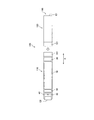
- FIG. 1 is a schematic diagram of a flavor generation device according to one embodiment.
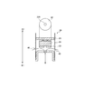
- FIG. 2 is a schematic diagram of an atomizing unit according to one embodiment.
- FIG. 3 is a schematic diagram illustrating an example of a configuration of the suction sensor according to the embodiment.
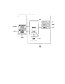
- FIG. 4 is a block diagram of the flavor generation device.
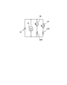
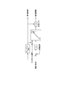
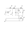
- FIG. 5 is a schematic diagram of an electric circuit of the flavor generation device including the atomization unit and the power supply unit.
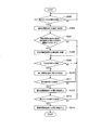
- FIG. 6 is a flowchart illustrating control by the control unit according to the embodiment.
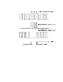
- FIG. 7 is a graph showing an example of power supply to the atomizing electric load and the flavoring electric load.
- FIG. 8 is a control block diagram illustrating switching control of the first switch and the second switch.
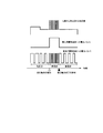
- FIG. 9 is a graph showing switching control of the first switch and the second switch.
- FIG. 10 is a graph showing another example of power supply to the atomizing electric load and the flavoring electric load.
- FIG. 11 is a graph showing still another example of power supply to the atomizing electric load and the flavoring electric load.
- FIG. 12 is a schematic diagram of an electric circuit of the flavor generation device including the atomization unit and the power supply unit in the fourth embodiment.
- FIG. 13 is a schematic diagram according to a modification of the electric circuit of the flavor generation device including the atomization unit and the power supply unit in the fourth embodiment.
- FIG. 14 is a schematic diagram of an electric circuit of the flavor generation device including the atomizing unit and the power supply unit in the fifth embodiment.
- FIG. 15 is a schematic diagram of an electric circuit of the flavor generation device including the atomizing unit and the power supply unit in the sixth embodiment.
- FIG. 16 is a schematic diagram of an electric circuit of the flavor generation device including the atomization unit and the power supply unit in the seventh embodiment.
- FIG. 17 is a schematic diagram of an electric circuit of a flavor generation device including an atomizing unit and a power supply unit according to the eighth embodiment.
- power from a power supply may be supplied to a plurality of electrical loads, such as two or more electrical heating elements.
- the inventor of the present application examined driving a single load or driving a plurality of loads at the same time in a flavor generation device having a plurality of loads.
- a plurality of loads may be electrically connected in parallel based on the power supply.
- the combined electrical resistance value of the plurality of loads becomes smaller than the individual electrical resistance value of each load. Therefore, when attempting to supply power from the power supply to a plurality of loads simultaneously, a current larger than the current output from the power supply when supplying power to one load is output from the power supply.
- a flavor generation device includes a power supply, a first load that atomizes an aerosol source or heats a flavor source, and a circuit that electrically connects a second load different from the first load. Acquiring a request to supply power to each of the first load and the second load, and controlling the circuit to supply power to each of the first load and the second load from the power supply based on the request.
- the configured control unit, and the control unit acquires the request to the first load and the request to the second load at the same time, or supplies power to the first load and the second
- the power or the amount of power discharged from the power supply is set to a maximum value when the power supply discharges simultaneously to the first load and the second load.
- Reduction configured to reduce power or maximum power It includes a stage, a.
- a power supply unit includes a power supply, a first load for atomizing an aerosol source or heating a flavor source, and a circuit for electrically connecting the power supply to a second load different from the first load. And acquiring a request to supply power to each of the first load and the second load, and controlling the circuit to supply power to each of the first load and the second load from the power supply based on the request.
- control unit configured as described above, wherein the control unit obtains the request to the first load and the request to the second load at the same time, or supplies power to the first load and
- the power or the amount of power discharged from the power supply may be controlled by the power supply discharging to the first load and the second load simultaneously.
- the circuit is configured such that when the request for the first load and the request for the second load are acquired at the same time, or when the power supply to the first load and the power supply to the second load are performed at the same time. Is controlled, the power or the amount of power discharged from the power supply is reduced. Therefore, even in such a case, the amount of discharge from the power supply can be reduced, and the remaining amount of the power supply can be prevented from rapidly decreasing and the power supply from being easily deteriorated.
- FIG. 1 is an exploded view showing a flavor generation device according to one embodiment.
- FIG. 2 is a schematic diagram of an atomizing unit according to one embodiment.
- FIG. 3 is a schematic diagram illustrating an example of a configuration of the suction sensor according to the embodiment.
- FIG. 4 is a block diagram of the flavor generation device.
- the flavor generation device 100 may be a non-combustion type flavor inhaler for sucking flavor without burning.
- the flavor generation device 100 may be a portable flavor inhaler.
- the flavor generation device 100 may have a shape extending along a predetermined direction A that is a direction from the non-mouth end E2 to the mouth end E1.
- the flavor generation device 100 may include one end E1 having the mouth 141 for sucking the flavor, and the other end E2 opposite to the mouth 141.
- the flavor generation device 100 may include a power supply unit 110 and an atomization unit 120.
- the atomization unit 120 may be configured to be detachable from the power supply unit 110 via mechanical connection portions 111 and 121.
- the later-described atomizing electric load 122R and flavor electric load 124R in the atomizing unit 120 are connected to a power supply provided in the power supply unit 110. 10 is electrically connected.
- the atomization unit 120 includes an aerosol source (flavor component source) that is sucked in a state of being atomized by a user, and an atomizing electric load 122R that atomizes the aerosol source with power from the power supply 10.
- aerosol source flavor component source
- atomizing electric load 122R that atomizes the aerosol source with power from the power supply 10.
- the atomizing electric load 122R may be any element that can adjust the amount of aerosol (the amount of flavor component) generated from the aerosol source according to the supplied electric power.
- the atomizing electric load 122R may be the atomizing temperature controller 122 that can adjust the temperature of the aerosol source.
- the atomizing electric load 122R constituting the atomizing temperature controller 122 may be a resistance heating element. It will be apparent to those skilled in the art that the amount of aerosol generated from the aerosol source will vary depending on the temperature of the aerosol source.
- the atomizing unit 120 may include a reservoir 122P, a wick 122Q, and an atomizing electric load 122R.
- the reservoir 122P may be configured to store a liquid aerosol source.
- the reservoir 122P may be, for example, a porous body made of a material such as a resin web.
- the wick 122Q may be a liquid holding member that transports the aerosol source from the reservoir 122P to the vicinity of the atomizing electric load 122R by using a capillary phenomenon.
- the wick 122Q can be made of, for example, glass fiber or porous ceramic.
- the atomizing electric load 122R heats the aerosol source held by the wick 122Q.
- the atomizing electric load 122R is configured by, for example, a resistance heating element (for example, a heating wire) wound around the wick 122Q.
- the electric load 122R for atomization may be, for example, a temperature controller 122 such as an electric heater.
- the atomizing electric load 122R may be a temperature controller having a function of heating and cooling the aerosol source held by the wick 122Q.
- the air that has flowed in from the inlet 125 through the flow path 127 passes near the atomizing electric load 122R in the atomizing unit 120.
- the aerosol generated at the atomizing electric load 122R flows toward the suction port 141 together with the inflowing air.
- the inlet 125 may be provided in at least one of the power supply unit 110 and the atomization unit 120.
- the aerosol source may be liquid at room temperature.
- a polyhydric alcohol such as glycerin or propylene glycol can be used as the aerosol source.
- the aerosol source may include a tobacco raw material or an extract derived from a tobacco raw material that releases a flavor component upon heating.
- the example of the aerosol source that is liquid at room temperature has been described in detail, but instead, an aerosol source that is solid at room temperature may be used.
- the atomizing electric load 122R may be in contact with or in proximity to the solid aerosol source to generate aerosol from the solid aerosol source.
- the atomizing unit 120 may include a flavor unit 130 that is configured to be replaceable.
- the flavor unit 130 may have a cylinder 131 that stores a flavor source (a suction component source).
- the cylinder 131 may include a membrane member 133 and a filter 132 through which air, aerosol, and the like can pass.
- a flavor source may be provided in a space defined by the membrane member 133 and the filter 132.
- the flavor generation device 100 has channels 127 and 128 that allow at least a part of the aerosol generated from the aerosol source to reach the outlet through the flavor source.
- the flavor source in the flavor unit 130 imparts a flavor component to the aerosol generated by the atomizing electric load 122R of the atomization unit 120.
- the flavor component provided to the aerosol by the flavor source is carried to the mouth 141 of the flavor generation device 100.
- the flavor source in the flavor unit 130 may be solid at room temperature.
- the flavor source is constituted by a raw material piece of a plant material that imparts a flavor-tasting component to the aerosol.
- a raw material piece constituting the flavor source a molded article obtained by molding a tobacco material such as chopped tobacco or tobacco raw material into granules can be used.
- the flavor source may be a molded article formed by molding the tobacco material into a sheet.
- the raw material piece which comprises a flavor source may be comprised by plants (for example, mint, herb, etc.) other than tobacco. Flavors such as menthol may be provided to the flavor source.
- the flavor source may be movably accommodated in a space defined by the membrane member 133 and the filter 132. In this case, the flavor source flows in the flavor unit 130 during use, and the bias of the flavor source in contact with the flavor electric load 124R is reduced, so that the flavor component can be stably released.
- the flavor source may be substantially fixed by being filled in the space formed by the membrane member 133 and the filter 132. In this case, heat can be efficiently transmitted from the flavor electric load 124R to the flavor source.
- the flavor electric load 124R provided in the atomization unit 120 may be located around the cylindrical body 131 of the flavor unit 130 attached to the atomization unit 120.
- the flavor electric load 124R may be configured to be able to adjust the amount of flavor (inhalation component) generated from the flavor source.
- the flavor electric load 124R may be an element that can adjust the amount of flavor generated from the flavor source according to the supplied power.
- the flavor electric load 124R may be a temperature controller 124 that can adjust the temperature of the flavor source.
- the temperature controller 124 may be constituted by a resistance heating element.
- the temperature controller 124 may be constituted by an induction heating element.
- the temperature controller 124 may be a cooling element such as a Peltier element. Further, the temperature controller 124 may be an element capable of performing both heating and cooling.
- a heat insulating material 126 may be provided outside the flavor electric load 124R. Thereby, it is possible to suppress the temperature difference between the outer edge temperature of the flavor generation device 100 and the outside air temperature from becoming too large. That is, it is possible to suppress the outer edge of the flavor generation device 100 from becoming too cold or too hot.
- the heat insulating material 126 can reduce the heat transfer loss from the flavor electric load 124R, and can perform temperature control with energy saving.
- the flavor generating device 100 may include a mouthpiece having a suction port for a user to suck a suction component.
- the mouthpiece may be configured to be detachable from the atomizing unit 120 or the flavoring unit 130, or may be configured as an integral unit. Alternatively, a part of the atomization unit 120 or the flavor unit 130 may serve as a mouthpiece.
- the flavor generation device 100 specifically, the atomization unit 120, includes a first flow path 128 that guides the aerosol to the mouth 141 through the flavor source, and a second flow path 129 that guides the aerosol to the mouth 141 without passing the flavor source. May be provided.
- the aerosol passing through the second channel 129 reaches the mouth 141 without being imparted with a flavor from a flavor source.
- the atomization unit 120 may include a flow rate adjustment unit (not shown) that adjusts the ratio between the flow rate of the first flow path 128 and the flow rate of the second flow path 129.
- the power supply unit 110 may include the power supply 10 and the control unit 50.
- the control unit 50 may include a memory 52 that stores information necessary for performing various controls necessary for the operation of the flavor generation device 100.
- the control unit 50 may perform various controls necessary for the operation of the flavor generation device 100. For example, the control unit 50 acquires a request to supply power to each of the atomizing electric load 122R and the flavoring electric load 124R, and based on the request, supplies the atomizing electric load 122R and the flavoring electric load 124R from the power supply 10. Control the electric circuit to supply power to each.
- the power supply request is defined based on output signals from the push button, the suction sensor 20, and the like, as described later.
- the control unit 50 may include a notification unit that issues a notification for notifying the user of various types of information as necessary.
- the notification unit may be, for example, an element that emits light, such as an LED, an element that emits sound, or a vibrator that emits vibration. Further, the notification unit may be configured by a combination of elements that emit light, sound, or vibration.
- the power supply 10 stores electric power required for the operation of the flavor generation device 100.
- the power supply 10 may be detachable from the power supply unit 110.
- the power source 10 may be a rechargeable battery such as a lithium ion secondary battery, an electric double layer capacitor, or a combination thereof.
- the control unit 50 may include a suction detection unit that detects a suction request operation by the user.
- the suction detection unit may be, for example, a suction sensor 20 that detects a user's suction operation.
- the suction detection unit may be, for example, a push button pressed by a user.
- the controller 50 generates a command for operating the atomizing electric load 122R and / or the flavoring electric load 124R when the suction detection unit detects the suction request operation.
- the control unit 50 may be configured to variably control the power supplied to the atomizing electric load 122R and the flavoring electric load 124R according to a mode designated by the user, the environment, or the like.
- the control unit 50 When the suction requesting operation is detected by the suction detection unit, the control unit 50 preferably supplies power from the power supply 10 to the atomizing electric load 122R and / or the flavor electric load 124R in the form of a power pulse. Thereby, the control unit 50 can control the power supplied to the atomizing electric load 122R and / or the flavor electric load 124R by adjusting the duty ratio of the pulse width modulation (PWM) or the pulse frequency modulation (PFM). it can.
- PWM pulse width modulation
- PFM pulse frequency modulation
- the flavor generation device 100 can estimate or acquire the temperature of the atomizing electric load 122R, and the second temperature sensor can estimate or acquire the temperature of the flavor source or the flavor electric load 124R.
- a temperature sensor 160 can estimate or acquire the temperature of the flavor source or the flavor electric load 124R.
- the first temperature sensor 150 and the second temperature sensor 160 may include a thermistor or a thermocouple.
- the suction sensor 20 may be configured to output an output value that fluctuates according to suction from the suction port. Specifically, the suction sensor 20 outputs a value (for example, a voltage value or a current value) that changes according to the flow rate of the air sucked from the non-mouth side to the mouth side (that is, the user's puff operation). Sensor. Examples of such a sensor include a condenser microphone sensor and a known flow sensor.
- FIG. 3 shows a specific example of the suction sensor 20.
- the suction sensor 20 illustrated in FIG. 3 has a sensor main body 21, a cover 22, and a substrate 23.
- the sensor main body 21 is composed of, for example, a capacitor.
- the electric capacity of the sensor main body 21 is changed by vibration (pressure) generated by air sucked from the inlet 125 (that is, air sucked from the non-mouth side to the mouth side).
- the cover 22 is provided on the suction side with respect to the sensor main body 21 and has an opening 40. By providing the cover 22 having the opening 40, the electric capacity of the sensor main body 21 is easily changed, and the response characteristics of the sensor main body 21 are improved.
- the substrate 23 outputs a value (here, a voltage value) indicating the electric capacity of the sensor body 21 (capacitor).
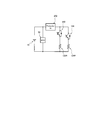
- FIG. 5 is a schematic diagram of an electric circuit of the flavor generation device 100 including the atomization unit 120 and the power supply unit 110. It should be noted that, in FIG. 5, the configuration of the electric circuit is simplified for the sake of convenience in order to explain the control of the atomizing electric load 122R and the flavoring electric load 124R by the control unit 50.
- the atomizing electric load (first load) 122R and the flavoring electric load (second load) 124R are electrically connected to the power supply 10 of the power supply unit 110. Connected to.
- the electric load for atomization (first load) 122R and the electric load for flavor (second load) 124R may be electrically connected in parallel with each other based on the power supply 10.
- the flavor generation device 100 includes a first switch 142 that opens and closes an electrical connection between the atomizing electric load 122R and the power supply 10, and a second switch that opens and closes an electric connection between the flavor electric load 124R and the power supply 10. And two switches 144.
- the first switch 142 and the second switch 144 may be electrically connected in parallel with each other based on the power supply 10.
- the first switch 142 and the second switch 144 are opened and closed by the control unit 50.
- the first switch 142 and the second switch 144 may be configured by, for example, MOSFETs.
- the first switch 142 and the second switch 144 are not limited to MOSFETs as long as they can open and close the electrical connection between each of the atomizing electric load 122R and the flavoring electric load 124R, and the power supply 10.
- An element may be used.
- the first switch 142 and the second switch 144 may be configured by, for example, a conductor.
- FIG. 6 is a flowchart illustrating an example of control by the control unit 50 according to an embodiment.
- the control unit 50 estimates or measures the temperature of the flavor electric load 124R (Step S305 and Step S306).
- the suction cycle can be detected, for example, by the user pressing a push button.
- the suction cycle is a state in which power can be supplied to the atomizing electric load 122R and / or the flavoring electric load 124R by a user's suction operation, and may include one or more user's suction operations. It is.
- the suction operation means an operation such as pressing of a push button by a user or an operation such as suction from a suction port.
- the temperature of the flavor electric load 124R can be estimated or measured by the second temperature sensor 160, for example.
- the electric load for flavor 124R is constituted by a PTC (Positive Temperature Coefficient) heater having a positive temperature coefficient
- the control unit 50 measures or estimates the electric resistance value of the electric load for flavor 124R to thereby control the flavor.
- the temperature of the electric load 124R can also be estimated.
- the flavor electric load 124R may be constituted by an NTC heater having a negative temperature coefficient instead of the PTC heater. This is because the electric resistance of the flavor electric load 124R changes depending on the temperature.
- the electric resistance value of the flavor electric load 124R can be estimated by measuring a voltage drop amount at the flavor electric load 124R with a voltage sensor.
- the control unit 50 determines whether or not the difference (absolute value of the difference) between the temperature of the flavor electric load 124R and the target temperature is larger than a predetermined threshold (step S307).
- the control unit 50 adjusts the power to the flavor electric load 124R, and controls the flavor electric load.
- 124R is controlled to be maintained near the target temperature (step S308).
- the predetermined threshold is an allowable value of a temperature error, and is set, for example, in a range of several degrees Celsius to less than 10 degrees Celsius.
- the power to the flavor electric load 124R can be supplied in the form of a power pulse.
- the temperature of the flavor electric load 124R can be controlled by adjusting the duty ratio in the pulse width modulation (PWM) or the pulse frequency modulation (PFM).
- PWM pulse width modulation
- PFM pulse frequency modulation
- the temperature control of the flavor electric load 124R can be performed, for example, by adjusting the duty ratio in pulse width modulation (PWM) or pulse frequency modulation (PWM) by feedback control.
- the control unit 50 monitors the presence or absence of the user's suction operation during the control of the flavor electric load 124R (step S309).
- the user's suction operation can be detected by, for example, the suction sensor 20 described above.
- the control unit 50 supplies power to the atomizing electric load 122R to heat the atomizing electric load 122R (Step S310).
- an aerosol is generated from the atomization unit 120.
- At least a part of the aerosol generated by the atomizing unit 120 is imparted with a flavor by passing through a flavor source. The user will inhale the flavored aerosol.
- the power to the atomizing electric load 122R can be supplied in the form of a power pulse.
- the temperature of the atomizing electric load 122R can be controlled by adjusting the duty ratio in pulse width modulation (PWM) or pulse frequency modulation (PFM).
- PWM pulse width modulation
- PFM pulse frequency modulation
- the temperature control of the atomizing electric load 122R can be performed, for example, by adjusting the duty ratio in pulse width modulation (PWM) or pulse frequency modulation (PFM) by feedback control.
- the present invention may be implemented by adjusting the duty ratio in pulse width modulation (PWM) or pulse frequency modulation (PFM) by feedforward control.
- the constant power control may be performed by increasing the duty ratio as the output voltage of the power supply 10 decreases.
- control unit 50 When the control unit 50 detects the end of the suction operation (step S311), it stops supplying power to the atomizing electric load 122R (step S312).
- the end of the suction operation can be detected by the suction sensor 20.
- the control unit 50 may stop supplying power to the atomizing electric load 122R even at a timing other than the detection of the end of the suction operation. For example, when the user continues the suction operation for a very long time, or when the abnormality of the electric load 122R for atomization or the power supply 10 is detected, the supply of power to the electric load 122R for atomization may be stopped.
- control unit 50 may stop supplying power to the flavor electric load 124R (step S314).
- the control unit 50 may determine that the suction cycle has ended, for example, when a predetermined push button is pressed by the user or when a predetermined period has elapsed from the end of the previous suction operation.
- the control unit 50 may determine that the suction cycle has ended when the suction operation has been detected a predetermined number of times during one suction cycle, or when a predetermined period has elapsed since the start of the suction cycle. Good.
- the timings of starting and ending power supply to the atomizing electric load 122R and the flavoring electric load 124R are different.
- power can be simultaneously supplied from the power supply 10 to the atomizing electric load 122R and the flavoring electric load 124R.
- the timing of starting and / or ending the supply of power to the atomizing electric load 122R and the flavoring electric load 124R may be the same. In this case, from the start to the end of the suction cycle, power can be simultaneously supplied from the power supply 10 to the atomizing electric load 122R and the flavoring electric load 124R.
- FIG. 7 shows a more specific example of power supply to the atomizing electric load 122R and the flavoring electric load 124R.
- a straight line indicates power supply to the atomizing electric load 122R.
- a broken line indicates power supply to the flavor electric load 124R.
- the dotted line indicates the amount of current discharged from the power supply.
- control unit 50 controls the electric circuit to supply power to the flavor electric load 124R during the suction cycle.
- control unit 50 controls the electric circuit to supply power to the atomizing electric load 122R in the form of a power pulse.
- the power pulse can be generated by opening and closing the first switch 142 and the second switch 144.
- the control unit 50 is configured not to simultaneously supply power from the power supply 10 to both the atomizing electric load 122R and the flavoring electric load 124R during the suction operation. . Specifically, the control unit 50 acquires a request for power supply to the atomizing electric load 122R and a request for power supply to the flavoring electric load 124R at the same time, or controls the atomizing electric load 122R. When the circuit is controlled so that the request for power supply and the power supply to the flavor electric load 124R are performed at the same time, the operation is performed so that the power supply 10 does not supply power to the atomizing electric load 122R and the flavor electric load 124R at the same time.
- control unit 50 may turn off the second switch 144 and stop the power supply to the flavor electric load 124R from the time of detecting the suction operation to the time of detecting the end of the suction operation.
- the combined electric resistance value of the atomizing electric load 122R and the flavoring electric load 124R becomes the atomizing electric load 122R or the flavoring electric load. Since the electric resistance of the load 124R is smaller than the single electric resistance, the amount of current discharged from the power supply 10 is larger than when only one of the atomizing electric load 122R and the flavoring electric load 124R is supplied. .
- the control unit 50 operates so that the power supply 10 does not supply power to the atomizing electric load 122R and the flavoring electric load 124R at the same time.
- the power is reduced from the maximum power or the maximum power when discharging to the atomizing electric load 122R and the flavoring electric load 124R simultaneously.
- the control unit 50 reduces the power or the amount of power discharged from the power supply 10 from the maximum power or the maximum power amount when the power supply 10 simultaneously discharges to the atomizing electric load 122R and the flavoring electric load 124R.
- It functions as the reducing means configured as described above. Accordingly, the load on the power supply 10 is reduced, and it is possible to suppress the remaining amount of the power supply 10 from rapidly decreasing and the power supply 10 from being easily deteriorated.
- control unit 50 as the reducing unit turns off the second switch 144 between the time when the suction operation is detected and the time when the suction operation is completed.
- control unit 50 as the reducing means turns on the second switch 144 even during the period from the detection of the suction operation to the detection of the end of the suction operation, to the electric load for flavor 124R. Supply power.
- FIG. 8 is a control block diagram illustrating switching control of the first switch 142 and the second switch 144.
- FIG. 9 is a graph showing switching control of the first switch 142 and the second switch 144. It should be noted that, instead of the power pulse in FIG. 7, the timing of the switching command to each of the first switch 142 and the second switch 144 is shown in FIG. Note that, in the following, the description of the same configuration as that of the first embodiment may be omitted.
- control unit 50 also supplies power pulses to the atomizing electric load 122R and the flavoring electric load 124R during the period from the detection of the suction operation to the detection of the end of the suction operation.
- the control unit 50 may perform feedback control or feedforward control using PWM control or PFM control, as in the first embodiment.
- the control unit 50 supplies an ON command to the second switch 144 during a period between ON commands to the first switch 142 (see FIG. D)).
- the control unit 50 may turn on the second switch 144 within the off-period of the first switch 142 even during the period from the detection of the suction operation to the detection of the end of the suction operation.
- Such control can be realized, for example, as follows. First, the switching cycle of the first switch 142 and the switching cycle of the second switch 144 are matched. In this case, if the switching timings of the first switch 142 and the second switch 144 are matched, the first switch 142 and the second switch 144 are simultaneously turned on. A command and an ON command to the second switch 144 are simultaneously generated (see FIGS. 9A and 9B).
- control unit 50 as a reducing unit may be configured to shift the switching phase of the second switch 144 from the switching phase of the first switch 142 by more than the ON period of the first switch 142 (FIG. 9). (C)).
- phase shift such shifting of the phase may be referred to as “phase shift”.
- the switching phase of the second switch 144 is shifted by the same amount as the ON period of the first switch 142 (see FIG. 9C).
- Such a phase shift determines the pulse width or duty ratio of the first switch 142 and then determines the amount of phase shift of the second switch 144 based on the ON period derived from the pulse width or duty ratio. This can be realized by setting (see also FIG. 8).
- the ON period of the second switch 144 starts within the OFF period of the first switch 142. Thereby, at the start of the ON period of the second switch 144, it is possible to suppress the first switch 142 and the second switch 144 from being simultaneously turned on. Therefore, the control unit 50 as the reduction unit can reduce the power or the amount of power discharged from the power supply 10 at least at the start of the ON period of the second switch 144.
- control unit 50 is configured to shift the switching phase of the second switch 144 from the switching phase of the first switch 142 more than the ON period of the first switch 142.
- a predetermined period occurs between the time when the OFF command is sent to the first switch 142 and the time when the ON command is sent to the second switch 144. Even if an off command is sent to the switch in the on state, there is a predetermined turn-off time until the switch is turned off. Therefore, the current from the power supply 10 slightly flows for a short time after the OFF command is sent to the first switch 142.
- the control unit 50 as the reducing unit can reduce the power or the amount of power discharged from the power supply 10 at least at the start of the ON period of the second switch 144.
- the control unit 50 as a reducing unit controls the first switch 142 so that the sum of the ON period of the first switch 142 and the ON period of the second switch 144 does not exceed the switching period during one switching period. At least one of the ON period and the ON period of the second switch 144 is set or corrected. In the following, adjusting any one of the ON periods in this manner may be referred to as “dead time compensation” (see FIG. 8). In the dead time compensation shown in FIG. 8, the ON period of the second switch 144 is shortened. This guarantees that an ON command is sent to the first switch 142 after an OFF command is sent to the second switch 144 again (see FIGS. 9C and 9D). Therefore, the control unit 50 as a reducing unit can suppress that the first switch 142 and the second switch 144 are simultaneously turned on.
- Such dead time compensation is performed based on the pulse width and the duty ratio of the electric power to the atomizing electric load 122R, or the pulse width and the duty ratio of the electric power to the flavor electric load 122R based on the ON period of the first switch 142.
- it can be realized by setting the upper limit of the ON period of the second switch 144. That is, the control unit 50 as the reduction unit is configured to set or correct the ON period in the switching control of the second switch 144 so as to reduce the power or the amount of power discharged from the power supply 10.
- the control unit 50 as the reducing unit reduces at least one of the proportional gain and the limiter upper limit in the feedback control so as to reduce the power supplied from the power supply 10 to the flavor electric load 124R. May be adjusted (see also FIG. 8). In this case, even when the power pulse to the flavor electric load 124R is variably configured by the feedback control, it is possible to prevent the power supplied from the power supply 10 to the flavor electric load 124R from increasing. it can.
- the control unit 50 as the reducing unit shifts the switching phase of the second switch 144 from the switching phase of the first switch 142 by more than the ON period of the first switch 142. It is configured. Alternatively, the control unit 50 may shift the switching phase of the first switch 142 from the switching phase of the second switch 144 by the ON period of the second switch 144 or more. More preferably, the control unit 50 may shift the switching phase of the first switch 142 from the switching phase of the second switch 144 more than the ON period of the second switch 144. Even in this case, the power pulse to the atomizing electric load 122R and the power pulse to the flavoring electric load 124R do not overlap with each other and are generated at shifted times.
- control unit 50 as a reducing unit outputs the maximum power or the maximum power when the power supply 10 simultaneously discharges the power or power amount discharged from the power supply 10 to the atomizing electric load 122R and the flavoring electric load 124R. It can be reduced from the amount.
- control unit 50 as the reducing unit sets or corrects the ON period in the switching control of the second switch 144 so as to reduce the power or the amount of power discharged from the power supply 10. It is configured to be. Instead, the control unit 50 as a reducing unit is configured to set or correct the ON period in the switching control of the first switch 142 so as to reduce the power or the amount of power discharged from the power supply 10. Is also good. That is, the ON period of the first switch 142 may be shortened.
- the control unit 50 When controlling the power supplied to the atomizing electric load 122R based on the feedback control, the control unit 50 performs the feedback control so as to reduce the power supplied from the power supply 10 to the atomizing electric load 122R. At least one of the proportional gain and the limiter upper limit may be adjusted.
- the control unit 50 performs the switching control so that the ON period of the first switch 142 and the ON period of the second switch 144 do not overlap. Instead, the control unit 50 may perform the switching control so that the ON period of the first switch 142 and the ON period of the second switch 144 partially overlap. Even in this case, by reducing the period during which both the first switch 142 and the second switch 144 are turned on, the control unit 50 as a reducing unit can reduce the power or the amount of power discharged from the power supply 10. Can be reduced from the maximum power or the maximum power when the power supply 10 simultaneously discharges to the atomizing electric load 122R and the flavoring electric load 124R.
- the control unit 50 determines the variable or mode in the switching control of the first switch 122 and the second switch. At least one of the variables and the modes in the switching control of 124 may be configured or corrected so as to reduce the power discharged from the power supply 10 or the amount of power.
- the control unit 50 as a reducing unit supplies the ON pulse of the first switch 142 and the second switch in a case where the power pulse is simultaneously supplied to both the atomizing electric load 122R and the flavoring electric load 124R.
- At least one of the 144 on-periods may be configured to be short.
- the second switch 144 may be used. Has a shorter on-period.
- control unit 50 shortens the on-period of the second switch 144 from the detection of the suction operation to the detection of the end of the suction operation.
- Such control can be realized by reducing the duty ratio of the PWM control.
- the ON period of the second switch 144 and the duty ratio of the PWM control are specific examples of variables in the switching control of the second switch 144.
- the control unit 50 as a reducing unit supplies the power pulse to both the atomizing electric load 122R and the flavoring electric load 124R at the same time. It is configured to shorten at least one of the switching periods of the switch 144.
- the control unit 50 may keep the switching duty ratio in the first switch 142 and the second switch 144. Thereby, in the PWM control, the width of each power pulse can be reduced.
- the control unit 50 shortens the switching cycle of the second switch 144 while maintaining the duty ratio of the second switch 144 from the detection of the suction operation to the detection of the end of the suction operation. doing.
- the switching cycle of the first switch 142 is a specific example of a variable in the switching control of the first switch 142.
- the switching cycle of the second switch 144 is a specific example of a variable in the switching control of the second switch 144.
- the control unit 50 when simultaneously supplying power pulses to both the atomizing electric load 122R and the flavoring electric load 124R, the control unit 50 performs feedback control or feedforward using PFM control instead of PWM control. Based on the control, at least one of the first switch 142 and the second switch 144 may be controlled. In this case, the control unit 50 reduces the power supplied to the flavor electric load 124R at the same time as the power supplied to the atomizing electric load 122R, or supplies the power supplied to the flavor electric load 124R at the same time.
- the duty ratio may be determined so as to reduce the power to the atomizing electric load 122R. By switching to the PFM control, the off period can be made variable without changing the pulse width.
- PWM control or PFM control for controlling the first switch 142 is a specific example of a mode in the switching control of the first switch 142.
- PWM control or PFM control for controlling the second switch 144 is a specific example of a mode in switching control of the second switch 144.
- (Fourth embodiment) 12 and 13 are schematic diagrams of an electric circuit of a flavor generation device including an atomizing unit and a power supply unit according to the fourth embodiment.
- the flavor generation device includes the protection integrated circuit 200 having a rated current value larger than a maximum current value that can supply power to one of the atomizing electric load 122R and the flavor electric load 124R.
- Such a protection integrated circuit 200 prevents a large current that may cause a problem in an electric circuit from flowing.
- the protection integrated circuit 200 is particularly useful when a control is performed in which the first switch 142 and the second switch 144 can be simultaneously turned on.
- an electric (power) fuse 210 having a rated current value larger than the maximum current value that can supply power to one of the atomizing electric load 122R and the flavoring electric load 124R is used. Is also good.
- the control unit 50 as a reducing unit controls the current (first current) supplied to the atomizing electric load 122R and the first current. At the same time, it is preferable to control the electric circuit so that the sum with the current (second current) supplied to the flavor electric load 124R does not exceed the above rated current.
- the above-described phase shift, dead time compensation, upper limit of the pulse width or the duty ratio so that the sum of the first current and the second current, that is, the maximum value of the current discharged from the power supply 10 does not exceed the rated current. And / or feedback control may be performed.
- the circuit opens when a current equal to or greater than the rated current flows for the rated time, so that the control unit 50 determines that the sum of the first current and the second current is less than the rated current value, or
- the first switch 142 and the second switch 144 may be controlled such that the overlapping period of the second current is shorter than the rated time.
- the protection integrated circuit 200 that cuts off the circuit or the electric fuse 210 itself is reduced. It may be used as a means.
- a thermal fuse may be used instead of the protection integrated circuit 200 or the electric fuse as described above (FIG. 13).
- the thermal fuse is blown when a current larger than the rated current flows for a predetermined time according to the current value. Therefore, in order to more reliably protect the electric circuit, the thermal fuse may have a rated current value that is equal to or less than half the current value that flows when the electric power is supplied to the atomizing electric load 122R and the atomizing electric load 124R at the same time. preferable.
- Such a thermal fuse can also be used as a reducing means.
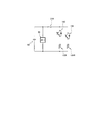
- FIG. 14 is a schematic diagram of an electric circuit of the flavor generation device including the atomizing unit and the power supply unit in the fifth embodiment.
- the circuit constituting the flavor generation device includes a regulator 300 that regulates a current output to at least one of the atomizing electric load 122R and the flavor electric load 124R.
- the regulator 300 is provided at a position where both the current supplied to the atomizing electric load 122R and the current supplied to the flavoring electric load 124R flow.
- the regulator 300 is provided between the node on the high potential side where the atomizing electric load 122R and the flavoring electric load 124R are connected in parallel and the positive electrode of the power supply 10. In this case, the regulator 300 adjusts the current output to both the atomizing electric load 122R and the flavoring electric load 124R.
- the regulator 300 is in a position where the current supplied to the atomizing electric load 122R flows but the current supplied to the flavoring electric load 124R does not flow, or the current supplied to the flavoring electric load 124R flows. May be provided at a position where the current supplied to the atomizing electric load 122R does not flow.
- the regulator 300 may be provided between the node on the high potential side and the first switch 142 or between the node on the high potential side and the second switch 144. In this case, the regulator 300 can adjust the current output to the atomizing electric load 122R or the flavoring electric load 124R.
- the control unit 50 acquires the power supply request to the atomization electric load 122R and the power supply request to the flavor electric load 124R at the same time, or supplies the power supply to the atomization electric load 122R and the flavor electric power.
- the current value or the power value output from the regulator 300 may be reduced. That is, the regulator 300 functions as at least a part of the reduction unit that reduces the current value.
- a linear regulator or a switching regulator may be used. When a switching regulator is used and the control unit 50 turns on only one of the first switch 142 and the second switch 144, the switching of the switching regulator may be stopped and only conduction may be performed.
- the regulator 300 for reducing the current value In the case where the regulator 300 for reducing the current value is used, the complicated control of the power pulse as described in the above embodiment can be omitted. However, the regulator 300 described in the fifth embodiment may be used in combination with the power pulse control described in the foregoing embodiment.
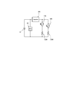
- FIG. 15 is a schematic diagram of an electric circuit of the flavor generation device including the atomizing unit and the power supply unit in the sixth embodiment.
- a first circuit 410 and a second circuit 420 connected in parallel with each other are provided instead of the regulator 300 in the fifth embodiment.
- a third switch 412 is provided on the first circuit 410.
- a fourth switch 422 is provided on the second circuit 420.
- the electric resistance value of the second circuit 420 is higher than the electric resistance value of the first circuit 410.
- a resistor 424 is provided on the second circuit 420.
- the control unit 50 can control the opening and closing of the third switch 412 and the fourth switch 422, respectively.
- the third switch 412 is on and the fourth switch 422 is off
- the discharge current from the power supply 10 passes through the first circuit 410 without passing through the second circuit 420.
- the third switch 412 is off and the fourth switch 422 is on
- the discharge current from the power supply 10 passes through the second circuit 420 without passing through the first circuit 410.
- the electric resistance value of the second circuit 420 is higher than the electric resistance value of the first circuit 410, if the second circuit 420 is operated without operating the first circuit 410, the second circuit 420 is operated.
- the passing current value is reduced. That is, the value of the current discharged by the power supply 10 can be reduced.
- the control unit 50 acquires the power supply request to the atomization electric load 122R and the power supply request to the flavor electric load 124R at the same time, or supplies the power supply to the atomization electric load 122R and the flavor electric power.
- the second circuit 420 may be operated without operating the first circuit 410. More specifically, when both the first switch 142 and the second switch 144 are turned on at the same time, the control unit 50 may cause the second circuit 420 to function without causing the first circuit 410 to function. .
- the controller 50 may cause the first circuit 410 to function without causing the second circuit 420 to function. Accordingly, when both the first switch 142 and the second switch 144 are simultaneously turned on, the control unit 50 can reduce the power or the amount of power discharged from the power supply 10. That is, the first circuit 410 and the second circuit 420 can be used as reduction means.
- FIG. 16 is a schematic diagram of an electric circuit of the flavor generation device including the atomization unit and the power supply unit in the seventh embodiment.
- the configurations of the power supply 10, the control unit 50, the atomizing electric load 122R, the flavor electric load 124R, the first switch 142, and the second switch 144 are the same as those in the first embodiment.
- the flavor generation device includes the auxiliary power supply 500 capable of discharging the electric load for atomization 122R and the electric load for flavor 124R.
- the auxiliary power supply 500, the atomizing electric load 122R, and the flavor electric load 124R may be electrically connected in parallel with each other based on the power supply 10.
- the discharge current from the auxiliary power supply 500 can flow to the atomizing electric load 122R and / or the flavoring electric load 124R.
- the auxiliary power supply 500 may preferably be a power supply that can be charged and discharged. In this case, the auxiliary power supply 500 is charged by the power from the power supply 10 when the charge amount is low. Conversely, when the charge amount of the auxiliary power supply 500 is high, the discharge current from the auxiliary power supply 500 flows to the atomizing electric load 122R and / or the flavor electric load 124R.
- the auxiliary power supply 500 preferably has a higher power density (W / kg) than the power supply 10.
- an electric double-layer capacitor EDLC, Electric double-layer capacitor
- the auxiliary power supply 500 functions as a reduction unit that reduces the power or the amount of power discharged from the power supply 10.
- the control unit 50 may be capable of acquiring a value relating to the remaining amount of the auxiliary power supply 500.
- the value regarding the remaining amount of the auxiliary power supply 500 may be, for example, the voltage of the auxiliary power supply 500.
- the voltage of the auxiliary power supply 500 can be obtained or estimated by the voltage sensor 510, for example.
- the control unit 50 be configured to control the circuit such that a value relating to the remaining amount of the auxiliary power supply 500, for example, the power or amount of power discharged from the power supply 10 decreases as the voltage increases.
- the power or amount of power discharged by the power supply 10 can be controlled by, for example, a converter including the switch 520, the backflow prevention diode 540, and the inductor 560.
- the converter is not limited to this, and may be any converter provided between the power supply 10 and the auxiliary power supply 500 and capable of converting and outputting at least one of the input current, voltage, and power. .
- the power or the amount of power discharged from the power supply 10 can also be controlled by adjusting the duty ratio of the power pulse by the switch 520 instead of the converter described above. As described above, by adjusting the power or the amount of power discharged from the power supply 10 based on the value regarding the remaining amount of the auxiliary power supply 500, the auxiliary power supply 500 can be effectively used.
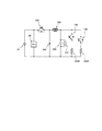
- FIG. 17 is a schematic diagram of an electric circuit of a flavor generation device including an atomizing unit and a power supply unit according to the eighth embodiment.
- the configurations of the power supply 10, the control unit 50, the atomizing electric load 122R, the flavor electric load 124R, the first switch 142 and the second switch 144 are substantially the same as those of the seventh embodiment.
- the position of the auxiliary power supply 500 is different from that of the seventh embodiment.
- the auxiliary power supply 500 is provided at a position where the discharge current can flow through the atomizing electric load 122R, but the discharge current cannot flow through the flavoring electric load 124R. That is, the auxiliary power supply 500 functions as an auxiliary power supply dedicated to the atomizing electric load 122R. It is preferable that the auxiliary power supply 500 can be charged and discharged as described in the seventh embodiment.
- the flavor generation device 100 further includes a fifth switch 146 that allows or prohibits the flow of a discharge current from the power supply 10 to the auxiliary power supply 500 and / or the atomizing electric load 122R.
- the fifth switch 146 is configured to be openable and closable by the control unit 50. Therefore, when the fifth switch 146 is on, the auxiliary power supply 500 can be charged by the power from the power supply 10.
- the first switch 142 can allow or prohibit the flow of the discharge current from the power supply 10 or the auxiliary power supply 500 to the atomizing electric load 122R.
- the second switch 144 can permit or prohibit the flow of the discharge current from the power supply 10 to the flavor electric load 124R.
- various modes can be realized by a combination of ON / OFF of the first switch 142, the second switch 144, and the fifth switch 146.
- the first switch 142, the second switch 144, and the fifth switch 146 When the first switch 142, the second switch 144, and the fifth switch 146 are all off, power is not supplied to the atomizing electric load 122R and the flavoring electric load 124R.
- the power supply 10 is a rechargeable secondary battery and the power supply 10 is charged from an external power supply, all of the first switch 142, the second switch 144, and the fifth switch 146 may be turned off. .
- the discharge current from the power supply 10 flows to the flavor electric load 124R, so that the flavor electric load 124R functions. be able to. In this case, power is not supplied to the atomizing electric load 122R. Further, since the power from the power supply 10 flows into the auxiliary power supply 500, the auxiliary power supply 500 can be charged.
- the discharge current flows from both the power supply 10 and the auxiliary power supply 500 to the atomizing electric load 122R.
- the electric load for use 122R can function. In this case, no electric power is supplied to the flavor electric load 124R. In this case, the discharge current from the power supply 10 can be reduced as compared with the case where power is supplied to the atomizing electric load 122R by the power supply 10 alone without using the auxiliary power supply 500.
- the power supply 10 and the auxiliary power supply 500 independently supply power to the flavor electric load 124R and the atomizing electric load 122R, respectively.
- the discharge current from the power supply 10 flows to the flavor electric load 124R. Furthermore, a discharge current flows from both the power supply 10 and the auxiliary power supply 500 to the atomizing electric load 122R. In this case, the discharge current from the power supply 10 can be reduced as compared with a case in which the power supply 10 alone supplies power to the atomizing electric load 122R and the flavoring electric load 124R simultaneously without using the auxiliary power supply 500. . Therefore, similarly to the seventh embodiment, the auxiliary power supply 500 functions as a reduction unit that reduces the power or the amount of power discharged from the power supply 10.
- the flow relating to the above-described embodiment can be executed by the control unit 50. That is, the control unit 50 may have a program that causes the flavor generation device 100 to execute the above-described method. Such a program is also included in the scope of the present invention. It should be noted that a storage medium storing the program is also included in the scope of the present invention. Such a storage medium may be, for example, a non-volatile storage medium readable by a computer.
- the first load specified in the claims is the atomizing electric load (first load) 122R
- the second load specified in the claims is the flavoring electric load (second load).
- the case where the load is 124R is specifically described.
- the first load may be any electric load that atomizes the aerosol source or heats the flavor source. Therefore, it should be noted that the first load may correspond to the flavor electric load 124R.
- the second load is not particularly limited as long as it is an electric load different from the first load.
- the second load may be, for example, a light emitting element such as an LED.
Landscapes
- Engineering & Computer Science (AREA)
- Power Engineering (AREA)
- Disinfection, Sterilisation Or Deodorisation Of Air (AREA)
- Charge And Discharge Circuits For Batteries Or The Like (AREA)
Abstract
This flavor-generating device includes: a circuit in which a power source, a first load for atomizing an aerosol source or heating a flavor source, and a second load different from the first load are electrically connected; a control unit configured so as to acquire a request for supply of power to each of the first load and the second load, and so as to control the circuit so that power is supplied from the power supply to each of the first load and the second load on the basis of the request; and a reducing means configured so that, when the control unit simultaneously acquires the request to the first load and the request to the second load, or when the control unit controls the circuit so that the supply of power to the first load and the supply of power to the second load are performed simultaneously, the electric power discharged from the power supply or the electric power amount is reduced to less than a maximum electric power for when the power supply discharges to the first load and the second load simultaneously or a maximum electric power amount.
Description
本発明は、香味生成装置、電源ユニット、香味生成装置を制御する方法、及びプログラムに関する。
The present invention relates to a flavor generation device, a power supply unit, a method for controlling a flavor generation device, and a program.
シガレットに代わり、エアロゾル源をヒータのような電気的負荷で霧化することによって生じたエアロゾル(香味)を味わう香味生成装置が知られている(特許文献1-3)。エアロゾル生成装置は、エアロゾル源を霧化又は香味源を加熱す加熱素子、加熱素子に電力を供給する電源、負荷や電源を制御する制御部を備える。
There is known a flavor generation device that tastes aerosol (flavor) generated by atomizing an aerosol source with an electric load such as a heater instead of cigarettes (Patent Documents 1-3). The aerosol generation device includes a heating element for atomizing an aerosol source or heating a flavor source, a power supply for supplying power to the heating element, and a control unit for controlling a load and a power supply.
特許文献2は、電力源によって給電され、外側ハウジングの遠位端における開口を介して吸い込まれた空気を加熱する第1の電気抵抗発熱体と、電力源によって給電され、エアロゾル形成材料及びタバコ材料を加熱する第2の電気抵抗発熱体と、を有する喫煙物品を開示する。
US Pat. No. 6,037,086 discloses a first electrical resistance heating element powered by a power source and heating air drawn through an opening at a distal end of the outer housing; an aerosol-forming material and a tobacco material powered by the power source. And a second electrical resistance heating element for heating the heating element.
特許文献3は、喫煙材を加熱するための複数の加熱シリンダーを有する喫煙材加熱装置を開示する。これらの加熱シリンダーは、電力によって電気的に駆動される。
Patent Document 3 discloses a smoking material heating device having a plurality of heating cylinders for heating the smoking material. These heating cylinders are electrically driven by electric power.
第1の特徴は、香味生成装置であって、電源と、エアロゾル源を霧化又は香味源を加熱する第1負荷と、前記第1負荷とは異なる第2負荷と、を電気的に接続する回路と、前記第1負荷と前記第2負荷のそれぞれへの給電の要求を取得し、前記要求に基づき前記電源から前記第1負荷と前記第2負荷のそれぞれへ給電をするよう前記回路を制御するよう構成された制御部と、前記制御部が、前記第1負荷への前記要求と前記第2負荷への前記要求とを同時期に取得した場合、又は前記第1負荷への給電と前記第2負荷への給電とを同時期に行うよう前記回路を制御する場合に、前記電源から放電される電力又は電力量を、前記電源が前記第1負荷と前記第2負荷へ同時に放電する場合の最大電力又は最大電力量より低減するよう構成された低減手段と、を含むことを要旨とする。
A first feature is a flavor generation device, which electrically connects a power source, a first load for atomizing an aerosol source or heating a flavor source, and a second load different from the first load. A circuit and a request to supply power to each of the first load and the second load; and controlling the circuit to supply power to each of the first load and the second load from the power supply based on the request. A control unit configured to perform the control unit, when the control unit obtains the request to the first load and the request to the second load at the same time, or when supplying power to the first load and When controlling the circuit to supply power to the second load at the same time, when the power supply discharges the power or the amount of power from the power supply to the first load and the second load simultaneously. Configured to be less than the maximum power or the maximum amount of power And summarized in that it includes a reducing means.
第2の特徴は、第1の特徴における香味生成装置であって、前記低減手段は、前記電源から前記第1負荷と前記第2負荷へ同時に給電されないよう構成されることを要旨とする。
A second feature is the flavor generation device according to the first feature, wherein the reduction means is configured not to be simultaneously supplied with power from the power supply to the first load and the second load.
第3の特徴は、第1の特徴又は第2の特徴における香味生成装置であって、前記回路は、前記第1負荷と前記電源の間の電気的な接続を開閉する第1開閉器と、前記第2負荷と前記電源の間の電気的な接続を開閉する第2開閉器と、を含み、前記第1開閉器のスイッチング周期と、前記第2開閉器のスイッチング周期は同じであり、前記低減手段は、前記第1開閉器のオン期間と前記第2開閉器のオン期間の和が、前記スイッチング周期を越えないように、前記第1開閉器のオン期間と前記第2開閉器のオン期間のうち少なくとも一方を設定又は補正するよう構成されることを要旨とする。
A third feature is the flavor generation device according to the first feature or the second feature, wherein the circuit is configured to open and close an electrical connection between the first load and the power supply; A second switch for opening and closing an electrical connection between the second load and the power supply, wherein a switching cycle of the first switch and a switching cycle of the second switch are the same, The reducing means includes an ON period of the first switch and an ON period of the second switch so that a sum of an ON period of the first switch and an ON period of the second switch does not exceed the switching cycle. The gist is that it is configured to set or correct at least one of the periods.
第4の特徴は、第3の特徴における香味生成装置であって、前記低減手段は、前記第1開閉器のスイッチングの位相を前記第2開閉器のスイッチングの位相から前記第2開閉器のオン期間以上ずらす、又は、前記第2開閉器のスイッチングの位相を前記第1開閉器のスイッチングの位相から前記第1開閉器のオン期間以上ずらすよう構成されることを要旨とする。
A fourth feature is the flavor generation device according to the third feature, wherein the reducing means changes the switching phase of the first switch from the switching phase of the second switch to turn on the second switch. The gist of the present invention is that the phase of the switching of the second switch is shifted from the phase of the switching of the first switch by at least the ON period of the first switch for at least the period.
第5の特徴は、第3の特徴又は第4の特徴における香味生成装置であって、前記低減手段は、前記第1開閉器のオン期間と前記第2開閉器のオン期間の和が、前記スイッチング周期未満になるように、前記第1開閉器のオン期間と前記第2開閉器のオン期間の少なくとも一方を設定又は補正し、前記第1開閉器のスイッチングの位相を前記第2開閉器のスイッチングの位相から前記第2開閉器のオン期間よりも大きくずらす、又は前記第2開閉器のスイッチングの位相を前記第1開閉器のスイッチングの位相から前記第1開閉器のオン期間よりも大きくずらすよう構成されることを要旨とする。
A fifth feature is the flavor generation device according to the third feature or the fourth feature, wherein the reduction unit is configured to determine that a sum of an on-period of the first switch and an on-period of the second switch is the same as the above. At least one of the ON period of the first switch and the ON period of the second switch is set or corrected so as to be shorter than the switching cycle, and the switching phase of the first switch is set to the second switch. The phase of switching is shifted more than the ON period of the second switch, or the phase of switching of the second switch is shifted from the phase of switching of the first switch more than the ON period of the first switch. The gist is that it is configured as follows.
第6の特徴は、第1の特徴における香味生成装置であって、前記回路は、前記第1負荷と前記電源の間の電気的な接続を開閉する第1開閉器と、前記第2負荷と前記電源の間の電気的な接続を開閉する第2開閉器と、を含み、前記低減手段は、前記第1開閉器のスイッチング制御における変数又はモードと、前記第2開閉器のスイッチング制御における変数又はモードのうち少なくとも一方を、前記電源から放電される電力又は電力量を低減するように設定又は補正するよう構成されることを要旨とする。
A sixth feature is the flavor generation device according to the first feature, wherein the circuit includes: a first switch that opens and closes an electrical connection between the first load and the power supply; A second switch for opening and closing an electrical connection between the power supplies, wherein the reducing means includes a variable or mode in switching control of the first switch and a variable in switching control of the second switch. Alternatively, at least one of the modes is set or corrected so as to reduce the power or the amount of power discharged from the power supply.
第7の特徴は、第6の特徴における香味生成装置であって、前記低減手段は、前記第1開閉器のオン期間と前記第2開閉器のオン期間のうちの少なくとも一方を短くするよう構成されることを要旨とする。
A seventh feature is the flavor generation device according to the sixth feature, wherein the reduction unit is configured to shorten at least one of an ON period of the first switch and an ON period of the second switch. It is the gist that it is done.
第8の特徴は、第6の特徴における香味生成装置であって、前記低減手段は、前記第1開閉器のスイッチング周期と前記第2開閉器のスイッチング周期のうちの少なくとも一方を短くするよう構成されることを要旨とする。
An eighth feature is the flavor generation device according to the sixth feature, wherein the reduction unit is configured to shorten at least one of a switching cycle of the first switch and a switching cycle of the second switch. It is the gist that it is done.
第9の特徴は、第6の特徴又は第8の特徴における香味生成装置であって、前記制御部は、PWM制御を用いたフィードバック制御に基づき、前記第1開閉器及び前記第2開閉器を制御可能なよう構成され、前記低減手段は、前記PWM制御に代えてPFM制御を用いたフィードバック制御に基づき、前記第1開閉器と前記第2開閉器の少なくとも一方を制御するよう構成されることを要旨とする。
A ninth feature is the flavor generation device according to the sixth feature or the eighth feature, wherein the control unit controls the first switch and the second switch based on feedback control using PWM control. The control means is configured to be controllable, and the reducing means is configured to control at least one of the first switch and the second switch based on feedback control using PFM control instead of the PWM control. Is the gist.
第10の特徴は、第1の特徴、第6の特徴から第9の特徴のいずれかにおける香味生成装置であって、前記低減手段は、前記第1負荷へ給電される電力と同時に前記第2負荷へ給電される電力を低減する、又は前記第2負荷へ給電される電力と同時に給電される前記第1負荷への電力を低減するよう構成されることを要旨とする。
A tenth feature is the flavor generation device according to any one of the first feature, the sixth feature to the ninth feature, wherein the reducing means is configured to simultaneously control the power supplied to the first load with the second load. The gist is configured to reduce the power supplied to the load or reduce the power supplied to the first load simultaneously with the power supplied to the second load.
第11の特徴は、第10の特徴における香味生成装置であって、前記制御部は、フィードバック制御に基づき、前記電源から前記第1負荷と前記第2負荷のいずれか一方へ給電される電力を制御するよう構成され、前記低減手段は、前記電源から前記第1負荷と前記第2負荷のいずれか一方へ給電される電力を低減するように、前記フィードバック制御における比例ゲインとリミッタ上限のうち少なくとも一方を調整するよう構成されることを要旨とする。
An eleventh feature is the flavor generation device according to the tenth feature, wherein the control unit controls the power supplied from the power supply to one of the first load and the second load based on feedback control. Control means, and the reducing means reduces at least one of a proportional gain and a limiter upper limit in the feedback control so as to reduce electric power supplied from the power supply to one of the first load and the second load. The gist is that one is adjusted.
第12の特徴は、第10の特徴における香味生成装置であって、前記回路は、前記第1負荷と前記第2負荷のうちの少なくとも一方に出力する電流を調整するレギュレータを含み、前記低減手段は、前記レギュレータが出力する電流値を低減させるよう前記レギュレータを制御するよう構成されることを要旨とする。
A twelfth feature is the flavor generation device according to the tenth feature, wherein the circuit includes a regulator for adjusting a current output to at least one of the first load and the second load, The gist of the invention is that the regulator is configured to control the regulator so as to reduce the current value output from the regulator.
第13の特徴は、第1の特徴から第11の特徴のいずれかにおける香味生成装置であって、前記回路は、第1回路と、前記第1回路と並列に接続され、かつ前記第1回路より電気抵抗値が高い第2回路と、を含み、前記低減手段は、前記第1回路を機能させることなく前記第2回路を機能させるよう構成されることを要旨とする。
A thirteenth feature is the flavor generation device according to any one of the first to eleventh features, wherein the circuit is connected in parallel with the first circuit, and the first circuit And a second circuit having a higher electric resistance value, wherein the reduction means is configured to function the second circuit without functioning the first circuit.
第14の特徴は、第1の特徴から第13の特徴のいずれかにおける香味生成装置であって、前記低減手段は、前記回路内に設けられ、かつ前記第1負荷と前記第2負荷の一方へ給電可能な最大電流値よりも大きい定格電流値を有する保護集積回路又は電気ヒューズを含むことを要旨とする。
A fourteenth feature is the flavor generation device according to any one of the first to thirteenth features, wherein the reduction unit is provided in the circuit, and is one of the first load and the second load. The gist of the present invention is to include a protection integrated circuit or an electric fuse having a rated current value larger than the maximum current value capable of supplying power to the power supply.
第15の特徴は、第14の特徴における香味生成装置であって、前記低減手段は、前記第1負荷へ給電される第1電流と、前記第1電流と同時に前記第2負荷へ給電される第2電流との和が、前記定格電流を越えないように、前記回路を制御するよう構成されることを要旨とする。
A fifteenth feature is the flavor generation device according to the fourteenth feature, wherein the reducing unit is supplied to the second load simultaneously with the first current supplied to the first load and the first current. The gist of the present invention is to control the circuit so that the sum of the second current and the second current does not exceed the rated current.
第16の特徴は、第1の特徴から第15の特徴のいずれかにおける香味生成装置であって、前記低減手段は、前記回路内に設けられ、かつ前記第1負荷と前記第2負荷へ同時に給電した場合に流入する電流値の半分以下の定格電流値を有する温度ヒューズを含むことを要旨とする。
A sixteenth feature is the flavor generation device according to any one of the first to fifteenth features, wherein the reduction unit is provided in the circuit, and is simultaneously applied to the first load and the second load. The gist of the present invention is to include a thermal fuse having a rated current value that is equal to or less than half of a current value that flows when power is supplied.
第17の特徴は、第1の特徴から第15の特徴のいずれかにおける香味生成装置であって、前記低減手段は、前記第1負荷及び前記第2負荷へ放電可能な補助電源を含むことを要旨とする。
A seventeenth feature is the flavor generation device according to any one of the first to fifteenth features, wherein the reduction unit includes an auxiliary power supply capable of discharging to the first load and the second load. Make a summary.
第18の特徴は、第17の特徴における香味生成装置であって、前記補助電源は、前記電源よりも高い出力密度を有することを要旨とする。
An eighteenth feature is the flavor generation device according to the seventeenth feature, wherein the auxiliary power source has a higher output density than the power source.
第19の特徴は、第17の特徴又は第18の特徴における香味生成装置であって、前記制御部又は前記低減手段は、前記補助電源の残量に関する値を取得可能であり、前記制御部又は前記低減手段は、前記補助電源の残量に関する値が大きいほど前記電源が放電する電力又は電力量を低減させるように、前記回路を制御するよう構成されることを要旨とする。
A nineteenth feature is the flavor generation device according to the seventeenth feature or the eighteenth feature, wherein the control unit or the reduction unit can acquire a value regarding the remaining amount of the auxiliary power supply, The reduction means is configured to control the circuit such that the power or the amount of power discharged from the power supply decreases as the value related to the remaining amount of the auxiliary power supply increases.
第20の特徴は、第1の特徴又は第19の特徴における香味生成装置であって、前記電源と前記補助電源は、前記第1負荷と前記第2負荷の少なくとも1つに対して並列接続され、前記回路は、前記電源と前記補助電源の間に設けられ、かつ入力された電流と電圧と電力のうち少なくとも1つの大きさを変換して出力可能な変換器を含むことを要旨とする。
A twentieth feature is the flavor generation device according to the first feature or the nineteenth feature, wherein the power supply and the auxiliary power supply are connected in parallel to at least one of the first load and the second load. The gist is that the circuit includes a converter provided between the power supply and the auxiliary power supply, and capable of converting and outputting at least one of the input current, voltage, and power.
第21の特徴は、香味生成装置用の電源ユニットであって、電源と、エアロゾル源を霧化又は香味源を加熱する第1負荷と、前記第1負荷とは異なる第2負荷とに前記電源を電気的に接続する回路と、前記第1負荷と前記第2負荷のそれぞれへの給電の要求を取得し、前記要求に基づき前記電源から前記第1負荷と前記第2負荷のそれぞれへ給電をするよう前記回路を制御するよう構成された制御部と、前記制御部が、前記第1負荷への前記要求と前記第2負荷への前記要求とを同時期に取得した場合、又は前記第1負荷への給電と前記第2負荷への給電とを同時期に行うよう前記回路を制御する場合に、前記電源から放電される電力又は電力量を、前記電源が前記第1負荷と前記第2負荷へ同時に放電する場合の最大電力又は最大電力量より低減するよう構成された低減手段と、を含むことを要旨とする。
A twenty-first feature is a power supply unit for a flavor generation device, wherein the power supply includes a power supply, a first load for atomizing an aerosol source or heating a flavor source, and a second load different from the first load. And a request for power supply to each of the first load and the second load, and supplying power from the power supply to each of the first load and the second load based on the request. A control unit configured to control the circuit so that the request to the first load and the request to the second load are obtained at the same time, or When controlling the circuit to perform power supply to a load and power supply to the second load at the same time, the power or the amount of power discharged from the power supply is determined by the power supply by the first load and the second load. Maximum power or maximum power when discharging simultaneously to the load And reducing means configured to reduce Ri, and summarized in that comprises a.
第22の特徴は、エアロゾル源を霧化又は香味源を加熱する第1負荷と、前記第1負荷とは異なる第2負荷と、を含む香味生成装置を制御する方法であって、前記第1負荷と前記第2負荷のそれぞれへの給電の要求を取得し、前記要求に基づき電源から前記第1負荷と前記第2負荷のそれぞれへ給電をするよう前記回路を制御するステップと、前記第1負荷への前記要求と前記第2負荷への前記要求とを同時期に取得した場合、又は前記第1負荷への給電と前記第2負荷への給電とを同時期に行うよう前記回路を制御する場合に、前記電源から放電される電力又は電力量を、前記電源が前記第1負荷と前記第2負荷へ同時に放電する場合の最大電力又は最大電力量より低減するステップと、を含むことを要旨とする。
A twenty-second feature is a method of controlling a flavor generation device including a first load for atomizing an aerosol source or heating a flavor source, and a second load different from the first load, wherein the first load is different from the first load. Obtaining a request for power supply to each of a load and the second load, and controlling the circuit to supply power to each of the first load and the second load from a power supply based on the request; When the request to the load and the request to the second load are acquired at the same time, or the circuit is controlled so that power supply to the first load and power supply to the second load are performed at the same time. Reducing the power or the amount of power discharged from the power supply from the maximum power or the maximum amount of power when the power supply discharges to the first load and the second load simultaneously. Make a summary.
第23の特徴は、第22の特徴における方法を香味生成装置に実行させるプログラムを要旨とする。
23The twenty-third feature is a summary of a program for causing a flavor generation device to execute the method according to the twenty-second feature.
以下において、実施形態について説明する。なお、以下の図面の記載において、同一又は類似の部分には、同一又は類似の符号を付している。ただし、図面は模式的なものであり、各寸法の比率などは現実のものとは異なる場合があることに留意すべきである。
Hereinafter, embodiments will be described. In the following description of the drawings, the same or similar parts are denoted by the same or similar reference numerals. However, it should be noted that the drawings are schematic and ratios of dimensions may be different from actual ones.
したがって、具体的な寸法などは以下の説明を参酌して判断すべきものである。また、図面相互間においても互いの寸法の関係や比率が異なる部分が含まれる場合があることは勿論である。
Therefore, specific dimensions and the like should be determined in consideration of the following description. In addition, it goes without saying that the drawings may include portions having different dimensional relationships and ratios.
[開示の概要]
特許文献2及び特許文献3に記載された装置では、電源からの電力は、2以上の電気加熱素子のような複数の電気的な負荷に供給され得る。本願の発明者は、複数の負荷を有する香味生成装置において、各負荷を単独で駆動したり、複数の負荷を同時期に駆動したりすることを検討した。この場合、負荷を独立制御するため、複数の負荷は電源を基準に電気的に並列に接続されていてよい。複数の負荷が電源を基準に電気的に並列に接続されていると、複数の負荷の合成の電気抵抗値は、各々の負荷の単独の電気抵抗値よりも小さくなる。したがって、電源から複数の負荷に同時に電力を供給しようとすると、1つの負荷に電力を供給する場合に電源から出力される電流よりも大きな電流が電源から出力される。 [Overview of disclosure]
In the devices described in U.S. Pat. Nos. 6,059,009 and 6,087,098, power from a power supply may be supplied to a plurality of electrical loads, such as two or more electrical heating elements. The inventor of the present application examined driving a single load or driving a plurality of loads at the same time in a flavor generation device having a plurality of loads. In this case, in order to independently control the loads, a plurality of loads may be electrically connected in parallel based on the power supply. When a plurality of loads are electrically connected in parallel with respect to the power supply, the combined electrical resistance value of the plurality of loads becomes smaller than the individual electrical resistance value of each load. Therefore, when attempting to supply power from the power supply to a plurality of loads simultaneously, a current larger than the current output from the power supply when supplying power to one load is output from the power supply.
また、単位時間あたりに放電する電力や電流が増大するほど、電源の劣化が促進されることが知られている。
電源 Also, it is known that as the power or current discharged per unit time increases, the deterioration of the power supply is promoted.
すなわち、複数の負荷を同時期に駆動しようとする場合、電源からの放電量が比較的大きくなり、電源の残量が急速に減ったり、電源の劣化が進みやすくなったりする。したがって、このような場合であっても、電源の残量が急速に減ったり、電源の劣化が進みやすくなったりすることを抑制することが望ましい。
In other words, when trying to drive a plurality of loads at the same time, the amount of discharge from the power supply becomes relatively large, and the remaining amount of the power supply decreases rapidly or the power supply deteriorates easily. Therefore, even in such a case, it is desirable to suppress the remaining amount of the power supply from rapidly decreasing and the power supply from being easily deteriorated.
一態様によれば、香味生成装置は、電源と、エアロゾル源を霧化又は香味源を加熱する第1負荷と、前記第1負荷とは異なる第2負荷と、を電気的に接続する回路と、前記第1負荷と前記第2負荷のそれぞれへの給電の要求を取得し、前記要求に基づき前記電源から前記第1負荷と前記第2負荷のそれぞれへ給電をするよう前記回路を制御するよう構成された制御部と、前記制御部が、前記第1負荷への前記要求と前記第2負荷への前記要求とを同時期に取得した場合、又は前記第1負荷への給電と前記第2負荷への給電とを同時期に行うよう前記回路を制御する場合に、前記電源から放電される電力又は電力量を、前記電源が前記第1負荷と前記第2負荷へ同時に放電する場合の最大電力又は最大電力量より低減するよう構成された低減手段と、を含む。
According to one aspect, a flavor generation device includes a power supply, a first load that atomizes an aerosol source or heats a flavor source, and a circuit that electrically connects a second load different from the first load. Acquiring a request to supply power to each of the first load and the second load, and controlling the circuit to supply power to each of the first load and the second load from the power supply based on the request. The configured control unit, and the control unit acquires the request to the first load and the request to the second load at the same time, or supplies power to the first load and the second When controlling the circuit to perform power supply to a load at the same time, the power or the amount of power discharged from the power supply is set to a maximum value when the power supply discharges simultaneously to the first load and the second load. Reduction configured to reduce power or maximum power It includes a stage, a.
一態様によれば、電源ユニットは、電源と、エアロゾル源を霧化又は香味源を加熱する第1負荷と、前記第1負荷とは異なる第2負荷とに前記電源を電気的に接続する回路と、前記第1負荷と前記第2負荷のそれぞれへの給電の要求を取得し、前記要求に基づき前記電源から前記第1負荷と前記第2負荷のそれぞれへ給電をするよう前記回路を制御するよう構成された制御部と、前記制御部が、前記第1負荷への前記要求と前記第2負荷への前記要求とを同時期に取得した場合、又は前記第1負荷への給電と前記第2負荷への給電とを同時期に行うよう前記回路を制御する場合に、前記電源から放電される電力又は電力量を、前記電源が前記第1負荷と前記第2負荷へ同時に放電する場合の最大電力又は最大電力量より低減するよう構成された低減手段と、を含む。
According to one aspect, a power supply unit includes a power supply, a first load for atomizing an aerosol source or heating a flavor source, and a circuit for electrically connecting the power supply to a second load different from the first load. And acquiring a request to supply power to each of the first load and the second load, and controlling the circuit to supply power to each of the first load and the second load from the power supply based on the request. The control unit configured as described above, wherein the control unit obtains the request to the first load and the request to the second load at the same time, or supplies power to the first load and When controlling the circuit to perform power supply to the two loads at the same time, the power or the amount of power discharged from the power supply may be controlled by the power supply discharging to the first load and the second load simultaneously. Configured to reduce below maximum power or maximum power And includes a reduction means, the.
上記態様によれば、第1負荷への要求と第2負荷への要求とを同時期に取得した場合、又は第1負荷への給電と第2負荷への給電とを同時期に行うよう回路を制御する場合に、電源から放電される電力又は電力量が低減される。したがって、このような場合であっても、電源からの放電量を低下し、電源の残量が急速に減ったり、電源の劣化が進みやすくなったりすることを抑制することができる。
According to the above aspect, the circuit is configured such that when the request for the first load and the request for the second load are acquired at the same time, or when the power supply to the first load and the power supply to the second load are performed at the same time. Is controlled, the power or the amount of power discharged from the power supply is reduced. Therefore, even in such a case, the amount of discharge from the power supply can be reduced, and the remaining amount of the power supply can be prevented from rapidly decreasing and the power supply from being easily deteriorated.
(香味生成装置)
以下において、一実施形態に係る香味生成装置について説明する。図1は、一実施形態に係る香味生成装置を示す分解図である。図2は、一実施形態に係る霧化ユニットの模式図である。図3は、一実施形態に係る吸引センサの構成の一例を示す模式図である。図4は、香味生成装置のブロック図である。 (Flavor generator)
Hereinafter, a flavor generation device according to an embodiment will be described. FIG. 1 is an exploded view showing a flavor generation device according to one embodiment. FIG. 2 is a schematic diagram of an atomizing unit according to one embodiment. FIG. 3 is a schematic diagram illustrating an example of a configuration of the suction sensor according to the embodiment. FIG. 4 is a block diagram of the flavor generation device.
香味生成装置100は、燃焼を伴わずに香味を吸引するための非燃焼型の香味吸引器であってよい。好ましくは、香味生成装置100は、携帯型の香味吸引器であってよい。香味生成装置100は、非吸口端E2から吸口端E1に向かう方向である所定方向Aに沿って延びる形状を有していてよい。この場合、香味生成装置100は、香味を吸引する吸口141を有する一方の端部E1と、吸口141とは反対側の他方の端部E2と、を含んでいてよい。
The flavor generation device 100 may be a non-combustion type flavor inhaler for sucking flavor without burning. Preferably, the flavor generation device 100 may be a portable flavor inhaler. The flavor generation device 100 may have a shape extending along a predetermined direction A that is a direction from the non-mouth end E2 to the mouth end E1. In this case, the flavor generation device 100 may include one end E1 having the mouth 141 for sucking the flavor, and the other end E2 opposite to the mouth 141.
香味生成装置100は、電源ユニット110及び霧化ユニット120を有していてよい。霧化ユニット120は、電源ユニット110に対して機械的な接続部分111,121を介して着脱可能に構成されていてよい。霧化ユニット120と電源ユニット110とが互いに機械的に接続されたときに、霧化ユニット120内の後述する霧化用電気負荷122R及び香味用電気負荷124Rは、電源ユニット110に設けられた電源10に電気的に接続される。
The flavor generation device 100 may include a power supply unit 110 and an atomization unit 120. The atomization unit 120 may be configured to be detachable from the power supply unit 110 via mechanical connection portions 111 and 121. When the atomizing unit 120 and the power supply unit 110 are mechanically connected to each other, the later-described atomizing electric load 122R and flavor electric load 124R in the atomizing unit 120 are connected to a power supply provided in the power supply unit 110. 10 is electrically connected.
霧化ユニット120は、ユーザにより霧化された状態で吸引されるエアロゾル源(香味成分源)と、電源10からの電力によりエアロゾル源を霧化する霧化用電気負荷122Rと、を有する。
The atomization unit 120 includes an aerosol source (flavor component source) that is sucked in a state of being atomized by a user, and an atomizing electric load 122R that atomizes the aerosol source with power from the power supply 10.
霧化用電気負荷122Rは、供給される電力に応じて、エアロゾル源から生成されるエアロゾル量(香味成分の量)を調整可能な素子であればよい。例えば、霧化用電気負荷122Rは、エアロゾル源の温度を調節可能な霧化用温度調節器122であってよい。一例として、霧化用温度調節器122を構成する霧化用電気負荷122Rは、抵抗加熱素子であってよい。当業者であれば、エアロゾル源の温度に応じて、エアロゾル源から生成されるエアロゾル量が変化することは明らかであろう。
電 気 The atomizing electric load 122R may be any element that can adjust the amount of aerosol (the amount of flavor component) generated from the aerosol source according to the supplied electric power. For example, the atomizing electric load 122R may be the atomizing temperature controller 122 that can adjust the temperature of the aerosol source. As an example, the atomizing electric load 122R constituting the atomizing temperature controller 122 may be a resistance heating element. It will be apparent to those skilled in the art that the amount of aerosol generated from the aerosol source will vary depending on the temperature of the aerosol source.
以下では、図1及び図2を参照しつつ、霧化ユニット120のより詳細な一例について説明する。霧化ユニット120は、リザーバ122Pと、ウィック122Qと、霧化用電気負荷122Rと、を有していてよい。リザーバ122Pは、液状のエアロゾル源を貯留するよう構成されていてよい。リザーバ122Pは、例えば、樹脂ウェブ等材料によって構成される多孔質体であってよい。ウィック122Qは、リザーバ122Pから毛管現象を利用してエアロゾル源を霧化用電気負荷122R近傍に輸送する液保持部材であってよい。ウィック122Qは、例えば、ガラス繊維や多孔質セラミックなどによって構成することができる。
Hereinafter, a more detailed example of the atomization unit 120 will be described with reference to FIGS. 1 and 2. The atomizing unit 120 may include a reservoir 122P, a wick 122Q, and an atomizing electric load 122R. The reservoir 122P may be configured to store a liquid aerosol source. The reservoir 122P may be, for example, a porous body made of a material such as a resin web. The wick 122Q may be a liquid holding member that transports the aerosol source from the reservoir 122P to the vicinity of the atomizing electric load 122R by using a capillary phenomenon. The wick 122Q can be made of, for example, glass fiber or porous ceramic.
霧化用電気負荷122Rは、ウィック122Qに保持されるエアロゾル源を加熱する。霧化用電気負荷122Rは、例えば、ウィック122Qに巻き回される抵抗発熱体(例えば、電熱線)によって構成される。
電 気 The atomizing electric load 122R heats the aerosol source held by the wick 122Q. The atomizing electric load 122R is configured by, for example, a resistance heating element (for example, a heating wire) wound around the wick 122Q.
霧化用電気負荷122Rは、例えば、電気ヒータのような温度調節器122であってよい。この代わりに、霧化用電気負荷122Rは、ウィック122Qに保持されるエアロゾル源を加熱及び冷却する機能を備えた温度調節器であってもよい。
The electric load 122R for atomization may be, for example, a temperature controller 122 such as an electric heater. Instead, the atomizing electric load 122R may be a temperature controller having a function of heating and cooling the aerosol source held by the wick 122Q.
インレット125から流路127を通って流入した空気は、霧化ユニット120内の霧化用電気負荷122R付近を通過する。霧化用電気負荷122Rのところで生成されたエアロゾルは、流入した空気とともに吸口141の方へ流れる。なお、インレット125は、電源ユニット110と霧化ユニット120の少なくとも一方に設けられていればよい。
The air that has flowed in from the inlet 125 through the flow path 127 passes near the atomizing electric load 122R in the atomizing unit 120. The aerosol generated at the atomizing electric load 122R flows toward the suction port 141 together with the inflowing air. Note that the inlet 125 may be provided in at least one of the power supply unit 110 and the atomization unit 120.
エアロゾル源は、常温で液体であってよい。例えば、エアロゾル源としては、グリセリンやプロピレングリコールといった多価アルコールを用いることができる。エアロゾル源は、加熱することによって香喫味成分を放出するたばこ原料やたばこ原料由来の抽出物を含んでいてもよい。
The aerosol source may be liquid at room temperature. For example, a polyhydric alcohol such as glycerin or propylene glycol can be used as the aerosol source. The aerosol source may include a tobacco raw material or an extract derived from a tobacco raw material that releases a flavor component upon heating.
なお、上記実施形態では、常温で液体のエアロゾル源についての例を詳細に説明したが、この代わりに、エアロゾル源は、常温で固体のものを用いることもできる。この場合、霧化用電気負荷122Rは、固体状のエアロゾル源からエアロゾルを発生させるため、固体状のエアロゾル源に接し、又は近接していてよい。
In the above embodiment, the example of the aerosol source that is liquid at room temperature has been described in detail, but instead, an aerosol source that is solid at room temperature may be used. In this case, the atomizing electric load 122R may be in contact with or in proximity to the solid aerosol source to generate aerosol from the solid aerosol source.
霧化ユニット120は、交換可能に構成された香味ユニット130を備えていてもよい。香味ユニット130は、香味源(吸引成分源)を収容する筒体131を有していてよい。筒体131は、空気やエアロゾル等が通過可能な膜部材133とフィルタ132とを含んでいてよい。膜部材133とフィルタ132とにより構成される空間内に香味源が設けられていてよい。
The atomizing unit 120 may include a flavor unit 130 that is configured to be replaceable. The flavor unit 130 may have a cylinder 131 that stores a flavor source (a suction component source). The cylinder 131 may include a membrane member 133 and a filter 132 through which air, aerosol, and the like can pass. A flavor source may be provided in a space defined by the membrane member 133 and the filter 132.
香味生成装置100は、エアロゾル源から生成されたエアロゾルの少なくとも一部を香味源を通して出口へ到達させる流路127,128を有する。これにより、香味ユニット130内の香味源は、霧化ユニット120の霧化用電気負荷122Rによって生成されたエアロゾルに香味成分を付与する。香味源によってエアロゾルに付与される香味成分は、香味生成装置100の吸口141に運ばれる。
The flavor generation device 100 has channels 127 and 128 that allow at least a part of the aerosol generated from the aerosol source to reach the outlet through the flavor source. Thus, the flavor source in the flavor unit 130 imparts a flavor component to the aerosol generated by the atomizing electric load 122R of the atomization unit 120. The flavor component provided to the aerosol by the flavor source is carried to the mouth 141 of the flavor generation device 100.
香味ユニット130内の香味源は、常温で固体であってよい。一例として、香味源は、エアロゾルに香喫味成分を付与する植物材料の原料片によって構成される。香味源を構成する原料片としては、刻みたばこやたばこ原料のようなたばこ材料を粒状に成形した成形体を用いることができる。この代わりに、香味源は、たばこ材料をシート状に成形した成形体であってもよい。また、香味源を構成する原料片は、たばこ以外の植物(例えば、ミント、ハーブ等)によって構成されてもよい。香味源には、メントールなどの香料が付与されていてもよい。
The flavor source in the flavor unit 130 may be solid at room temperature. As an example, the flavor source is constituted by a raw material piece of a plant material that imparts a flavor-tasting component to the aerosol. As a raw material piece constituting the flavor source, a molded article obtained by molding a tobacco material such as chopped tobacco or tobacco raw material into granules can be used. Alternatively, the flavor source may be a molded article formed by molding the tobacco material into a sheet. Moreover, the raw material piece which comprises a flavor source may be comprised by plants (for example, mint, herb, etc.) other than tobacco. Flavors such as menthol may be provided to the flavor source.
香味源は、膜部材133とフィルタ132とにより構成される空間内で流動可能に収容されていてもよい。この場合、使用時に香味ユニット130内で香味源が流動し、香味用電気負荷124Rと接触する香味源の偏りが少なくなるため、安定的に香味成分を放出することができる。
The flavor source may be movably accommodated in a space defined by the membrane member 133 and the filter 132. In this case, the flavor source flows in the flavor unit 130 during use, and the bias of the flavor source in contact with the flavor electric load 124R is reduced, so that the flavor component can be stably released.
この代わりに、香味源は、膜部材133とフィルタ132とにより構成される空間内で充填されることで、実質的に固定されていてもよい。この場合には、香味用電気負荷124Rから香味源に熱を効率的に伝えることができる。
Instead of this, the flavor source may be substantially fixed by being filled in the space formed by the membrane member 133 and the filter 132. In this case, heat can be efficiently transmitted from the flavor electric load 124R to the flavor source.
霧化ユニット120に設けられた香味用電気負荷124Rは、霧化ユニット120に取り付けられた香味ユニット130の筒体131の周りに位置していてよい。香味用電気負荷124Rは、香味源から生成される香味(吸引成分)の量を調整可能に構成されていてよい。香味用電気負荷124Rは、供給される電力に応じて、香味源から生成される香味の量を調整できる素子であってよい。例えば、香味用電気負荷124Rは、香味源の温度を調節可能な温度調節器124であってよい。温度調節器124は、抵抗加熱素子によって構成されていてよい。温度調節器124は、誘導加熱素子によって構成されていてもよい。この代わりに、温度調節器124は、例えばペルチェ素子のような冷却素子であってもよい。また、温度調節器124は、加熱と冷却の両方を実施できる素子であってもよい。
The flavor electric load 124R provided in the atomization unit 120 may be located around the cylindrical body 131 of the flavor unit 130 attached to the atomization unit 120. The flavor electric load 124R may be configured to be able to adjust the amount of flavor (inhalation component) generated from the flavor source. The flavor electric load 124R may be an element that can adjust the amount of flavor generated from the flavor source according to the supplied power. For example, the flavor electric load 124R may be a temperature controller 124 that can adjust the temperature of the flavor source. The temperature controller 124 may be constituted by a resistance heating element. The temperature controller 124 may be constituted by an induction heating element. Alternatively, the temperature controller 124 may be a cooling element such as a Peltier element. Further, the temperature controller 124 may be an element capable of performing both heating and cooling.
香味用電気負荷124Rの外側には、断熱材126が設けられていてもよい。これにより、香味生成装置100の外縁の温度と外気温の温度差が大きくなり過ぎることを抑制することができる。すなわち、香味生成装置100の外縁が冷たくなり過ぎたり、熱くなり過ぎたりすることを抑制することができる。また、断熱材126によって、香味用電気負荷124Rからの伝熱ロスを低減することもでき、省エネルギーでの温度調節が可能となる。
断 熱 A heat insulating material 126 may be provided outside the flavor electric load 124R. Thereby, it is possible to suppress the temperature difference between the outer edge temperature of the flavor generation device 100 and the outside air temperature from becoming too large. That is, it is possible to suppress the outer edge of the flavor generation device 100 from becoming too cold or too hot. In addition, the heat insulating material 126 can reduce the heat transfer loss from the flavor electric load 124R, and can perform temperature control with energy saving.
香味生成装置100は、使用者が吸引成分を吸引するための吸引口を有するマウスピースを含んでいてよい。マウスピースは、霧化ユニット120又は香味ユニット130に着脱可能に構成されていてもよく、一体不可分に構成されていてもよい。または、霧化ユニット120又は香味ユニット130の一部が、マウスピースの役割を果たしてもよい。
The flavor generating device 100 may include a mouthpiece having a suction port for a user to suck a suction component. The mouthpiece may be configured to be detachable from the atomizing unit 120 or the flavoring unit 130, or may be configured as an integral unit. Alternatively, a part of the atomization unit 120 or the flavor unit 130 may serve as a mouthpiece.
また、香味生成装置100、具体的には霧化ユニット120は、エアロゾルを香味源を通して吸口141へ導く第1流路128と、エアロゾルを香味源を通さず吸口141へ導く第2流路129と、を有していてもよい。第2流路129を通るエアロゾルは、香味源から香味を付与されることなく、吸口141へ到達する。この場合、霧化ユニット120は、第1流路128の流量と第2流路129の流量との割合を調整する不図示の流量調整手段を含んでいてもよい。
Further, the flavor generation device 100, specifically, the atomization unit 120, includes a first flow path 128 that guides the aerosol to the mouth 141 through the flavor source, and a second flow path 129 that guides the aerosol to the mouth 141 without passing the flavor source. May be provided. The aerosol passing through the second channel 129 reaches the mouth 141 without being imparted with a flavor from a flavor source. In this case, the atomization unit 120 may include a flow rate adjustment unit (not shown) that adjusts the ratio between the flow rate of the first flow path 128 and the flow rate of the second flow path 129.
電源ユニット110は、電源10及び制御部50を有していてよい。制御部50は、香味生成装置100の動作に必要な各種の制御を実施するために必要な情報を記憶するメモリ52を有していてもよい。
The power supply unit 110 may include the power supply 10 and the control unit 50. The control unit 50 may include a memory 52 that stores information necessary for performing various controls necessary for the operation of the flavor generation device 100.
制御部50は、香味生成装置100の動作に必要な各種の制御を行ってもよい。例えば、制御部50は、霧化用電気負荷122Rと香味用電気負荷124Rのそれぞれへの給電の要求を取得し、この要求に基づき電源10から霧化用電気負荷122Rと香味用電気負荷124Rのそれぞれへの給電するよう電気回路を制御する。給電の要求は、後述するように押ボタンや吸引センサ20等からの出力信号に基づき規定される。
The control unit 50 may perform various controls necessary for the operation of the flavor generation device 100. For example, the control unit 50 acquires a request to supply power to each of the atomizing electric load 122R and the flavoring electric load 124R, and based on the request, supplies the atomizing electric load 122R and the flavoring electric load 124R from the power supply 10. Control the electric circuit to supply power to each. The power supply request is defined based on output signals from the push button, the suction sensor 20, and the like, as described later.
また、制御部50は、必要に応じて、各種の情報をユーザに知らせるための通知を発する通知部を備えていてもよい。通知部は、例えばLEDのように光を発する素子、音を発生する素子、又は振動を発するバイブレータであってもよい。また、通知部は、光、音又は振動を発する素子の組み合わせによって構成されていてもよい。
The control unit 50 may include a notification unit that issues a notification for notifying the user of various types of information as necessary. The notification unit may be, for example, an element that emits light, such as an LED, an element that emits sound, or a vibrator that emits vibration. Further, the notification unit may be configured by a combination of elements that emit light, sound, or vibration.
電源10は、香味生成装置100の動作に必要な電力を蓄える。電源10は、電源ユニット110に対して着脱可能であってよい。電源10は、例えばリチウムイオン二次電池のような再充電可能な電池や、電気二重層キャパシタや、これらの組合せであってよい。
The power supply 10 stores electric power required for the operation of the flavor generation device 100. The power supply 10 may be detachable from the power supply unit 110. The power source 10 may be a rechargeable battery such as a lithium ion secondary battery, an electric double layer capacitor, or a combination thereof.
制御部50は、ユーザによる吸引要求動作を検知する吸引検知ユニットを含んでいてよい。吸引検知ユニットは、例えばユーザの吸引動作を検出する吸引センサ20であってよい。この代わりに、吸引検知ユニットは、例えばユーザにより押される押しボタンであってもよい。
The control unit 50 may include a suction detection unit that detects a suction request operation by the user. The suction detection unit may be, for example, a suction sensor 20 that detects a user's suction operation. Alternatively, the suction detection unit may be, for example, a push button pressed by a user.
制御部50は、吸引検知ユニットによって吸引要求動作が検出されたら、霧化用電気負荷122R及び/又は香味用電気負荷124Rを動作させるための指令を生成する。制御部50は、ユーザによって指定されたモード、又は環境等に応じて、霧化用電気負荷122Rと香味用電気負荷124Rに供給する電力を可変に制御するように構成されていてもよい。
The controller 50 generates a command for operating the atomizing electric load 122R and / or the flavoring electric load 124R when the suction detection unit detects the suction request operation. The control unit 50 may be configured to variably control the power supplied to the atomizing electric load 122R and the flavoring electric load 124R according to a mode designated by the user, the environment, or the like.
吸引検知ユニットによって吸引要求動作が検出されたら、制御部50は、電力パルスの形態で、電源10から霧化用電気負荷122R及び/又は香味用電気負荷124Rに電力を供給することが好ましい。これにより、制御部50は、パルス幅変調(PWM)又はパルス周波数変調(PFM)のデューティ比の調整により霧化用電気負荷122R及び/又は香味用電気負荷124Rに供給する電力を制御することができる。
When the suction requesting operation is detected by the suction detection unit, the control unit 50 preferably supplies power from the power supply 10 to the atomizing electric load 122R and / or the flavor electric load 124R in the form of a power pulse. Thereby, the control unit 50 can control the power supplied to the atomizing electric load 122R and / or the flavor electric load 124R by adjusting the duty ratio of the pulse width modulation (PWM) or the pulse frequency modulation (PFM). it can.
香味生成装置100は、必要に応じて、霧化用電気負荷122Rの温度を推定又は取得可能な第1温度センサ150と、香味源又は香味用電気負荷124Rの温度を推定又は取得可能な第2温度センサ160と、を有していてもよい。一例として、第1温度センサ150と第2温度センサ160は、サーミスタや熱電対から構成されていてもよい。
As needed, the flavor generation device 100 can estimate or acquire the temperature of the atomizing electric load 122R, and the second temperature sensor can estimate or acquire the temperature of the flavor source or the flavor electric load 124R. And a temperature sensor 160. As an example, the first temperature sensor 150 and the second temperature sensor 160 may include a thermistor or a thermocouple.
吸引センサ20は、吸口からの吸引に応じて変動する出力値を出力するよう構成されていてよい。具体的には、吸引センサ20は、非吸口側から吸口側に向けて吸引される空気の流量(すなわち、ユーザのパフ動作)に応じて変化する値(例えば、電圧値又は電流値)を出力するセンサであってよい。そのようなセンサとして、例えば、コンデンサマイクロフォンセンサや公知の流量センサなどが挙げられる。
The suction sensor 20 may be configured to output an output value that fluctuates according to suction from the suction port. Specifically, the suction sensor 20 outputs a value (for example, a voltage value or a current value) that changes according to the flow rate of the air sucked from the non-mouth side to the mouth side (that is, the user's puff operation). Sensor. Examples of such a sensor include a condenser microphone sensor and a known flow sensor.
図3は、吸引センサ20の具体的一例を示している。図3に例示された吸引センサ20は、センサ本体21と、カバー22と、基板23と、を有する。センサ本体21は、例えば、コンデンサによって構成されている。センサ本体21の電気容量は、インレット125から吸引される空気(すなわち、非吸口側から吸口側に向けて吸引される空気)によって生じる振動(圧力)によって変化する。カバー22は、センサ本体21に対して吸口側に設けられており、開口40を有する。開口40を有するカバー22を設けることによって、センサ本体21の電気容量が変化しやすく、センサ本体21の応答特性が向上する。基板23は、センサ本体21(コンデンサ)の電気容量を示す値(ここでは、電圧値)を出力する。
FIG. 3 shows a specific example of the suction sensor 20. The suction sensor 20 illustrated in FIG. 3 has a sensor main body 21, a cover 22, and a substrate 23. The sensor main body 21 is composed of, for example, a capacitor. The electric capacity of the sensor main body 21 is changed by vibration (pressure) generated by air sucked from the inlet 125 (that is, air sucked from the non-mouth side to the mouth side). The cover 22 is provided on the suction side with respect to the sensor main body 21 and has an opening 40. By providing the cover 22 having the opening 40, the electric capacity of the sensor main body 21 is easily changed, and the response characteristics of the sensor main body 21 are improved. The substrate 23 outputs a value (here, a voltage value) indicating the electric capacity of the sensor body 21 (capacitor).
(第1実施例)
図5は、霧化ユニット120及び電源ユニット110を含む香味生成装置100の電気回路の模式図である。図5では、制御部50による霧化用電気負荷122Rと香味用電気負荷124Rの制御を説明するために、電気回路の構成が便宜上、簡略化して示されていることに留意されたい。 (First embodiment)
FIG. 5 is a schematic diagram of an electric circuit of theflavor generation device 100 including the atomization unit 120 and the power supply unit 110. It should be noted that, in FIG. 5, the configuration of the electric circuit is simplified for the sake of convenience in order to explain the control of the atomizing electric load 122R and the flavoring electric load 124R by the control unit 50.
図5は、霧化ユニット120及び電源ユニット110を含む香味生成装置100の電気回路の模式図である。図5では、制御部50による霧化用電気負荷122Rと香味用電気負荷124Rの制御を説明するために、電気回路の構成が便宜上、簡略化して示されていることに留意されたい。 (First embodiment)
FIG. 5 is a schematic diagram of an electric circuit of the
霧化ユニット120が電源ユニット110に機械的に接続されたとき、霧化用電気負荷(第1負荷)122Rと香味用電気負荷(第2負荷)124Rは、電源ユニット110の電源10と電気的に接続される。霧化用電気負荷(第1負荷)122R及び香味用電気負荷(第2負荷)124Rは、電源10を基準に、互いに電気的に並列に接続されていてよい。
When the atomizing unit 120 is mechanically connected to the power supply unit 110, the atomizing electric load (first load) 122R and the flavoring electric load (second load) 124R are electrically connected to the power supply 10 of the power supply unit 110. Connected to. The electric load for atomization (first load) 122R and the electric load for flavor (second load) 124R may be electrically connected in parallel with each other based on the power supply 10.
香味生成装置100は、霧化用電気負荷122Rと電源10の間の電気的接続を開閉する第1開閉器142と、香味用電気負荷124Rと電源10との間の電気的接続を開閉する第2開閉器144と、を含んでいてよい。第1開閉器142及び第2開閉器144は、電源10を基準に、互いに電気的に並列に接続されていてよい。
The flavor generation device 100 includes a first switch 142 that opens and closes an electrical connection between the atomizing electric load 122R and the power supply 10, and a second switch that opens and closes an electric connection between the flavor electric load 124R and the power supply 10. And two switches 144. The first switch 142 and the second switch 144 may be electrically connected in parallel with each other based on the power supply 10.
第1開閉器142及び第2開閉器144は、制御部50によって開閉される。第1開閉器142及び第2開閉器144は、例えばMOSFETにより構成されていてよい。なお、第1開閉器142及び第2開閉器144は、霧化用電気負荷122Rと香味用電気負荷124Rそれぞれと電源10の間の電気的接続を開閉可能であれば、MOSFETに限らず様々な素子を用いてよい。別の一例として、第1開閉器142及び第2開閉器144は、例えばコンダクタにより構成されていてよい。
制 御 The first switch 142 and the second switch 144 are opened and closed by the control unit 50. The first switch 142 and the second switch 144 may be configured by, for example, MOSFETs. The first switch 142 and the second switch 144 are not limited to MOSFETs as long as they can open and close the electrical connection between each of the atomizing electric load 122R and the flavoring electric load 124R, and the power supply 10. An element may be used. As another example, the first switch 142 and the second switch 144 may be configured by, for example, a conductor.
第1開閉器142が閉じている(オン状態)場合、電源10から霧化用電気負荷122Rへ電力が供給可能となる。第2開閉器144が閉じている(オン状態)場合、電源10から香味用電気負荷124Rへ電力が供給可能となる。第1開閉器142と第2開閉器144の両方が閉じている(オン状態)場合、電源10から、霧化用電気負荷122Rと香味用電気負荷124Rの両方へ同時に電力が供給可能となる。
(4) When the first switch 142 is closed (ON state), power can be supplied from the power supply 10 to the atomizing electric load 122R. When the second switch 144 is closed (ON state), power can be supplied from the power supply 10 to the flavor electric load 124R. When both the first switch 142 and the second switch 144 are closed (ON state), power can be simultaneously supplied from the power supply 10 to both the atomizing electric load 122R and the flavoring electric load 124R.
図6は、一実施形態に係る制御部50による制御の一例を示すフローチャートである。
FIG. 6 is a flowchart illustrating an example of control by the control unit 50 according to an embodiment.
制御部50は吸引サイクルの開始を検知すると、香味用電気負荷124Rの温度を推定又は測定する(ステップS305及びステップS306)。吸引サイクルは、例えばユーザによる押しボタンの押下等によって検知することができる。なお、吸引サイクルは、ユーザの吸引動作により霧化用電気負荷122R及び/又は香味用電気負荷124Rへの給電が可能な状態な状態であり、1又は複数回のユーザの吸引動作を含み得るサイクルである。また、吸引動作は、ユーザによる押しボタンの押下のような動作や、吸口からの吸引のような動作を意味する。
When the control unit 50 detects the start of the suction cycle, the control unit 50 estimates or measures the temperature of the flavor electric load 124R (Step S305 and Step S306). The suction cycle can be detected, for example, by the user pressing a push button. Note that the suction cycle is a state in which power can be supplied to the atomizing electric load 122R and / or the flavoring electric load 124R by a user's suction operation, and may include one or more user's suction operations. It is. In addition, the suction operation means an operation such as pressing of a push button by a user or an operation such as suction from a suction port.
香味用電気負荷124Rの温度は、例えば第2温度センサ160によって推定又は測定することができる。この代わりに、香味用電気負荷124Rを正の温度係数を持つPTC(Positive Temperature Coefficient)ヒータで構成し、制御部50は、香味用電気負荷124Rの電気抵抗値を測定又は推定することによって、香味用電気負荷124Rの温度を推定することもできる。なお、PTCヒータに代えて負の温度係数を持つNTCヒータで香味用電気負荷124Rを構成することもできる。これは、香味用電気負荷124Rの電気抵抗値が温度に依存して変化するためである。なお、香味用電気負荷124Rの電気抵抗値は、香味用電気負荷124Rでの電圧降下量を電圧センサによって測定することで推定可能である。
The temperature of the flavor electric load 124R can be estimated or measured by the second temperature sensor 160, for example. Instead, the electric load for flavor 124R is constituted by a PTC (Positive Temperature Coefficient) heater having a positive temperature coefficient, and the control unit 50 measures or estimates the electric resistance value of the electric load for flavor 124R to thereby control the flavor. The temperature of the electric load 124R can also be estimated. It should be noted that the flavor electric load 124R may be constituted by an NTC heater having a negative temperature coefficient instead of the PTC heater. This is because the electric resistance of the flavor electric load 124R changes depending on the temperature. The electric resistance value of the flavor electric load 124R can be estimated by measuring a voltage drop amount at the flavor electric load 124R with a voltage sensor.
次に、制御部50は、香味用電気負荷124Rの温度と目標温度との差分(差分の絶対値)が、所定の閾値よりも大きいかどうか判断する(ステップS307)。香味用電気負荷124Rの温度と目標温度との差分(差分の絶対値)が、所定の閾値よりも大きい場合、制御部50は、香味用電気負荷124Rへの電力を調整し、香味用電気負荷124Rが目標温度付近に維持されるよう制御する(ステップS308)。所定の閾値は、温度の誤差の許容値であり、例えば数℃~10℃未満の範囲に設定される。
Next, the control unit 50 determines whether or not the difference (absolute value of the difference) between the temperature of the flavor electric load 124R and the target temperature is larger than a predetermined threshold (step S307). When the difference (absolute value of the difference) between the temperature of the flavor electric load 124R and the target temperature is larger than a predetermined threshold, the control unit 50 adjusts the power to the flavor electric load 124R, and controls the flavor electric load. 124R is controlled to be maintained near the target temperature (step S308). The predetermined threshold is an allowable value of a temperature error, and is set, for example, in a range of several degrees Celsius to less than 10 degrees Celsius.
香味用電気負荷124Rへの電力は、電力パルスの形態で供給することができる。この場合、パルス幅変調(PWM)又はパルス周波数変調(PFM)におけるデューティ比の調節により、香味用電気負荷124Rの温度を制御することができる。具体的には、香味用電気負荷124Rの温度制御は、例えば、フィードバック制御によってパルス幅変調(PWM)又はパルス周波数変調(PWM)におけるデューティ比を調節することにより実施することができる。
(4) The power to the flavor electric load 124R can be supplied in the form of a power pulse. In this case, the temperature of the flavor electric load 124R can be controlled by adjusting the duty ratio in the pulse width modulation (PWM) or the pulse frequency modulation (PFM). Specifically, the temperature control of the flavor electric load 124R can be performed, for example, by adjusting the duty ratio in pulse width modulation (PWM) or pulse frequency modulation (PWM) by feedback control.
また、香味用電気負荷124Rの温度と目標温度との差分(差分の絶対値)が、所定の閾値以下の場合、香味用電気負荷124Rへの電力の制御を行わなくてもよい。PWMを用いる場合は、デューティ比を0%に調整することで、香味用電気負荷124Rへの電力の供給が停止される。
In addition, when the difference (absolute value of the difference) between the temperature of the flavor electric load 124R and the target temperature is equal to or less than a predetermined threshold value, it is not necessary to control the electric power to the flavor electric load 124R. When PWM is used, the supply of power to the flavor electric load 124R is stopped by adjusting the duty ratio to 0%.
制御部50は、香味用電気負荷124Rの制御中に、ユーザの吸引動作の有無を監視する(ステップS309)。ユーザの吸引動作は、例えば前述した吸引センサ20によって検知することができる。
The control unit 50 monitors the presence or absence of the user's suction operation during the control of the flavor electric load 124R (step S309). The user's suction operation can be detected by, for example, the suction sensor 20 described above.
ユーザの吸引動作が検知されると、制御部50は、霧化用電気負荷122Rに電力を供給し、霧化用電気負荷122Rを加熱する(ステップS310)。これにより、霧化ユニット120からエアロゾルが生成される。霧化ユニット120で生成されたエアロゾルの少なくとも一部は、香味源を通ることにより、香味が付与される。ユーザは、香味が付与されたエアロゾルを吸引することになる。
When the user's suction operation is detected, the control unit 50 supplies power to the atomizing electric load 122R to heat the atomizing electric load 122R (Step S310). Thereby, an aerosol is generated from the atomization unit 120. At least a part of the aerosol generated by the atomizing unit 120 is imparted with a flavor by passing through a flavor source. The user will inhale the flavored aerosol.
霧化用電気負荷122Rへの電力は、電力パルスの形態で供給することができる。この場合、パルス幅変調(PWM)又はパルス周波数変調(PFM)におけるデューティ比の調節により、霧化用電気負荷122Rの温度を制御することができる。具体的には、霧化用電気負荷122Rの温度制御は、例えば、フィードバック制御によってパルス幅変調(PWM)又はパルス周波数変調(PFM)におけるデューティ比を調節することにより実施することができる。別の一例として、フィードフォワード制御によってパルス幅変調(PWM)又はパルス周波数変調(PFM)におけるデューティ比を調節することにより実施してもよい。また、電源10の出力電圧の低下に従い、デューティ比を増大させることで、定電力制御を実施してもよい。
(4) The power to the atomizing electric load 122R can be supplied in the form of a power pulse. In this case, the temperature of the atomizing electric load 122R can be controlled by adjusting the duty ratio in pulse width modulation (PWM) or pulse frequency modulation (PFM). Specifically, the temperature control of the atomizing electric load 122R can be performed, for example, by adjusting the duty ratio in pulse width modulation (PWM) or pulse frequency modulation (PFM) by feedback control. As another example, the present invention may be implemented by adjusting the duty ratio in pulse width modulation (PWM) or pulse frequency modulation (PFM) by feedforward control. Further, the constant power control may be performed by increasing the duty ratio as the output voltage of the power supply 10 decreases.
制御部50は、吸引動作の終了を検知すると(ステップS311)、霧化用電気負荷122Rへの電力の供給を停止する(ステップS312)。ここで、吸引動作の終了は、吸引センサ20によって検知することができる。
When the control unit 50 detects the end of the suction operation (step S311), it stops supplying power to the atomizing electric load 122R (step S312). Here, the end of the suction operation can be detected by the suction sensor 20.
また、制御部50は、吸引動作の終了の検知以外のタイミングであっても、霧化用電気負荷122Rへの電力の供給を停止してもよい。例えば、ユーザが非常に長く吸引動作を継続した場合や、霧化用電気負荷122Rや電源10の異常を検知した場合に、霧化用電気負荷122Rへの電力の供給を停止してもよい。
The control unit 50 may stop supplying power to the atomizing electric load 122R even at a timing other than the detection of the end of the suction operation. For example, when the user continues the suction operation for a very long time, or when the abnormality of the electric load 122R for atomization or the power supply 10 is detected, the supply of power to the electric load 122R for atomization may be stopped.
制御部50は、吸引サイクルの終了を検知すると(ステップS313)、香味用電気負荷124Rへの電力の供給を停止すればよい(ステップS314)。制御部50は、例えば、ユーザにより所定の押しボタンが押下された場合や、前回の吸引動作の終了から所定の期間が経過した場合に、吸引サイクルの終了と判断してもよい。この代わりに、制御部50は、1回の吸引サイクル中に吸引動作を所定回数検知した場合や、吸引サイクルの開始から所定の期間が経過した場合に、吸引サイクルが終了したと判断してもよい。
When the control unit 50 detects the end of the suction cycle (step S313), the control unit 50 may stop supplying power to the flavor electric load 124R (step S314). The control unit 50 may determine that the suction cycle has ended, for example, when a predetermined push button is pressed by the user or when a predetermined period has elapsed from the end of the previous suction operation. Alternatively, the control unit 50 may determine that the suction cycle has ended when the suction operation has been detected a predetermined number of times during one suction cycle, or when a predetermined period has elapsed since the start of the suction cycle. Good.
前述した制御フローでは、霧化用電気負荷122Rと香味用電気負荷124Rへの電力の供給の開始及び終了のタイミングが異なっている。この場合、ステップS308とステップS312の間で、電源10から霧化用電気負荷122Rと香味用電気負荷124Rへ同時に電力が供給され得る。この代わりに、霧化用電気負荷122Rと香味用電気負荷124Rへの電力の供給の開始及び/又は終了のタイミングは、同じであってもよい。この場合、吸引サイクルの開始から終了まで、電源10から霧化用電気負荷122Rと香味用電気負荷124Rへ同時に電力が供給され得る。
で は In the control flow described above, the timings of starting and ending power supply to the atomizing electric load 122R and the flavoring electric load 124R are different. In this case, between step S308 and step S312, power can be simultaneously supplied from the power supply 10 to the atomizing electric load 122R and the flavoring electric load 124R. Instead, the timing of starting and / or ending the supply of power to the atomizing electric load 122R and the flavoring electric load 124R may be the same. In this case, from the start to the end of the suction cycle, power can be simultaneously supplied from the power supply 10 to the atomizing electric load 122R and the flavoring electric load 124R.
図7は、霧化用電気負荷122Rと香味用電気負荷124Rへの電力供給のより具体的な一例を示している。図7において、直線(中段のライン)は、霧化用電気負荷122Rへの電力供給を示している。破線(下段のライン)は、香味用電気負荷124Rへの電力供給を示している。点線(上段のライン)は、電源から放電される電流量を示している。
FIG. 7 shows a more specific example of power supply to the atomizing electric load 122R and the flavoring electric load 124R. In FIG. 7, a straight line (middle line) indicates power supply to the atomizing electric load 122R. A broken line (lower line) indicates power supply to the flavor electric load 124R. The dotted line (upper line) indicates the amount of current discharged from the power supply.
前述したように、制御部50は、吸引サイクル中、香味用電気負荷124Rへ給電を行うよう電気回路を制御する。また、制御部50は、給電サイクル中に吸引動作を検知すると、電力パルスの形態で、霧化用電気負荷122Rへ給電を行うよう電気回路を制御する。電力パルスは、第1開閉器142と第2開閉器144の開閉により生成できる。
As described above, the control unit 50 controls the electric circuit to supply power to the flavor electric load 124R during the suction cycle. When detecting the suction operation during the power supply cycle, the control unit 50 controls the electric circuit to supply power to the atomizing electric load 122R in the form of a power pulse. The power pulse can be generated by opening and closing the first switch 142 and the second switch 144.
第1実施例では、図7に示すように、制御部50は、吸引動作中に、電源10から霧化用電気負荷122Rと香味用電気負荷124Rの両方へ同時には給電されないよう構成されている。具体的には、制御部50は、霧化用電気負荷122Rへの給電の要求と香味用電気負荷124Rへの給電の要求とを同時期に取得した場合、又は霧化用電気負荷122Rへの給電の要求と香味用電気負荷124Rへの給電とを同時期に行うよう回路を制御する場合に、電源10から霧化用電気負荷122Rと香味用電気負荷124Rへ同時に給電されないように動作する。
In the first embodiment, as shown in FIG. 7, the control unit 50 is configured not to simultaneously supply power from the power supply 10 to both the atomizing electric load 122R and the flavoring electric load 124R during the suction operation. . Specifically, the control unit 50 acquires a request for power supply to the atomizing electric load 122R and a request for power supply to the flavoring electric load 124R at the same time, or controls the atomizing electric load 122R. When the circuit is controlled so that the request for power supply and the power supply to the flavor electric load 124R are performed at the same time, the operation is performed so that the power supply 10 does not supply power to the atomizing electric load 122R and the flavor electric load 124R at the same time.
具体的一例では、制御部50は、吸引動作の検知から吸引動作終了の検知までの間、第2開閉器144をOFFにし、香味用電気負荷124Rへの給電を停止すればよい。
In a specific example, the control unit 50 may turn off the second switch 144 and stop the power supply to the flavor electric load 124R from the time of detecting the suction operation to the time of detecting the end of the suction operation.
仮に、霧化用電気負荷122Rと香味用電気負荷124Rに同時に給電を行うと、霧化用電気負荷122Rと香味用電気負荷124Rの合成の電気抵抗値は霧化用電気負荷122R又は香味用電気負荷124Rの単独の電気抵抗値よりも小さくなるため、電源10から放電される電流量は、霧化用電気負荷122Rと香味用電気負荷124Rのいずれか一方にのみ給電を行う場合よりも大きくなる。
If power is simultaneously supplied to the atomizing electric load 122R and the flavoring electric load 124R, the combined electric resistance value of the atomizing electric load 122R and the flavoring electric load 124R becomes the atomizing electric load 122R or the flavoring electric load. Since the electric resistance of the load 124R is smaller than the single electric resistance, the amount of current discharged from the power supply 10 is larger than when only one of the atomizing electric load 122R and the flavoring electric load 124R is supplied. .
本実施例では、制御部50は、電源10から霧化用電気負荷122Rと香味用電気負荷124Rへ同時に給電されないように動作するため、電源10から放電される電力又は電力量が、電源10が霧化用電気負荷122Rと香味用電気負荷124Rへ同時に放電する場合の最大電力又は最大電力量より低減される。言い換えると、制御部50は、電源10から放電される電力又は電力量を、電源10が霧化用電気負荷122Rと香味用電気負荷124Rへ同時に放電する場合の最大電力又は最大電力量より低減するよう構成された低減手段として機能する。これにより、電源10にかかる負荷が低減され、電源10の残量が急速に減ったり、電源10の劣化が進みやすくなったりすることを抑制することができる。
In the present embodiment, the control unit 50 operates so that the power supply 10 does not supply power to the atomizing electric load 122R and the flavoring electric load 124R at the same time. The power is reduced from the maximum power or the maximum power when discharging to the atomizing electric load 122R and the flavoring electric load 124R simultaneously. In other words, the control unit 50 reduces the power or the amount of power discharged from the power supply 10 from the maximum power or the maximum power amount when the power supply 10 simultaneously discharges to the atomizing electric load 122R and the flavoring electric load 124R. It functions as the reducing means configured as described above. Accordingly, the load on the power supply 10 is reduced, and it is possible to suppress the remaining amount of the power supply 10 from rapidly decreasing and the power supply 10 from being easily deteriorated.
(第2実施例)
第1実施例では、低減手段としての制御部50は、吸引動作の検知から吸引動作終了の検知までの間、第2開閉器144をOFFにした。この代わりに、第2実施例では、低減手段としての制御部50は、吸引動作の検知から吸引動作終了の検知までの間にも、第2開閉器144をオンにし、香味用電気負荷124Rへ電力を供給する。 (Second embodiment)
In the first embodiment, thecontrol unit 50 as the reducing unit turns off the second switch 144 between the time when the suction operation is detected and the time when the suction operation is completed. Instead of this, in the second embodiment, the control unit 50 as the reducing means turns on the second switch 144 even during the period from the detection of the suction operation to the detection of the end of the suction operation, to the electric load for flavor 124R. Supply power.
第1実施例では、低減手段としての制御部50は、吸引動作の検知から吸引動作終了の検知までの間、第2開閉器144をOFFにした。この代わりに、第2実施例では、低減手段としての制御部50は、吸引動作の検知から吸引動作終了の検知までの間にも、第2開閉器144をオンにし、香味用電気負荷124Rへ電力を供給する。 (Second embodiment)
In the first embodiment, the
以下、図8及び図9を参照し、第2実施例に係る制御の一例について説明する。図8は、第1開閉器142と第2開閉器144のスイッチング制御を示す制御ブロック図である。図9は、第1開閉器142と第2開閉器144のスイッチング制御を示すグラフである。図7における電力パルスに代えて、図9では第1開閉器142と第2開閉器144それぞれへのスイッチング指令のタイミングが示されている点に留意されたい。なお、以下では、第1実施例と同様の構成については、説明を省略することがあることに留意されたい。
Hereinafter, an example of the control according to the second embodiment will be described with reference to FIGS. 8 and 9. FIG. 8 is a control block diagram illustrating switching control of the first switch 142 and the second switch 144. FIG. 9 is a graph showing switching control of the first switch 142 and the second switch 144. It should be noted that, instead of the power pulse in FIG. 7, the timing of the switching command to each of the first switch 142 and the second switch 144 is shown in FIG. Note that, in the following, the description of the same configuration as that of the first embodiment may be omitted.
第2実施例では、制御部50は、吸引動作の検知から吸引動作終了の検知までの間にも、霧化用電気負荷122Rと香味用電気負荷124Rに電力パルスを供給する。制御部50は、第1実施形態と同様に、PWM制御又はPFM制御を用いたフィードバック制御やフィードフォワード制御を行ってよい。
In the second embodiment, the control unit 50 also supplies power pulses to the atomizing electric load 122R and the flavoring electric load 124R during the period from the detection of the suction operation to the detection of the end of the suction operation. The control unit 50 may perform feedback control or feedforward control using PWM control or PFM control, as in the first embodiment.
第2実施例では、図9で示すように、制御部50は、第1開閉器142へのオン指令どうしの間の期間に、第2開閉器144へオン指令を供給する(図9の(D)参照)。言い換えると、制御部50は、吸引動作の検知から吸引動作終了の検知までの間であっても、第1開閉器142のオフ期間内に第2開閉器144をオンにすればよい。
In the second embodiment, as shown in FIG. 9, the control unit 50 supplies an ON command to the second switch 144 during a period between ON commands to the first switch 142 (see FIG. D)). In other words, the control unit 50 may turn on the second switch 144 within the off-period of the first switch 142 even during the period from the detection of the suction operation to the detection of the end of the suction operation.
このような制御は、例えば以下のように実現することができる。まず、第1開閉器142のスイッチング周期と、第2開閉器144のスイッチング周期を一致させておく。この場合に、第1開閉器142と第2開閉器144のスイッチングのタイミングを一致させると、第1開閉器142と第2開閉器144が同時にオンになるため、第1開閉器142へのオン指令と、第2開閉器144へのオン指令とが同時に生成される(図9の(A)及び(B)参照)。
制 御 Such control can be realized, for example, as follows. First, the switching cycle of the first switch 142 and the switching cycle of the second switch 144 are matched. In this case, if the switching timings of the first switch 142 and the second switch 144 are matched, the first switch 142 and the second switch 144 are simultaneously turned on. A command and an ON command to the second switch 144 are simultaneously generated (see FIGS. 9A and 9B).
したがって、低減手段としての制御部50は、第2開閉器144のスイッチングの位相を第1開閉器142のスイッチングの位相から第1開閉器142のオン期間以上ずらすよう構成されていてよい(図9(C)を参照)。なお、以下では、このように位相をずらすことを、「位相シフト」と称することがある。
Therefore, the control unit 50 as a reducing unit may be configured to shift the switching phase of the second switch 144 from the switching phase of the first switch 142 by more than the ON period of the first switch 142 (FIG. 9). (C)). Hereinafter, such shifting of the phase may be referred to as “phase shift”.
図9の(C)に示す例では、第1開閉器142のオン期間と同じだけ、第2開閉器144のスイッチングの位相をずらしている(図9の(C)参照)。このような位相シフトは、第1開閉器142のパルス幅又はデューティ比を決定した後に、当該パルス幅、又はデューティ比から導出されるオン期間に基づいて第2開閉器144の位相シフトの量を設定することで実現できる(図8も参照)。
In the example shown in FIG. 9C, the switching phase of the second switch 144 is shifted by the same amount as the ON period of the first switch 142 (see FIG. 9C). Such a phase shift determines the pulse width or duty ratio of the first switch 142 and then determines the amount of phase shift of the second switch 144 based on the ON period derived from the pulse width or duty ratio. This can be realized by setting (see also FIG. 8).
上記のような位相シフトにより、第1開閉器142のオフ期間内に、第2開閉器144のオン期間が開始される。これにより、第2開閉器144のオン期間の開始時において、第1開閉器142と第2開閉器144が同時にオンになることを抑制することができる。したがって、低減手段としての制御部50は、少なくとも第2開閉器144のオン期間の開始時において、電源10がから放電される電力又は電力量を低減させることができる。
オ ン Due to the above-described phase shift, the ON period of the second switch 144 starts within the OFF period of the first switch 142. Thereby, at the start of the ON period of the second switch 144, it is possible to suppress the first switch 142 and the second switch 144 from being simultaneously turned on. Therefore, the control unit 50 as the reduction unit can reduce the power or the amount of power discharged from the power supply 10 at least at the start of the ON period of the second switch 144.
より好ましくは、制御部50は、第2開閉器144のスイッチングの位相を第1開閉器142のスイッチングの位相から第1開閉器142のオン期間よりも大きくずらすよう構成される。これにより、第1開閉器142へオフ指令が送られてから、第2開閉器144へオン指令が送られるまでの間に所定の期間が生じる。オン状態にある開閉器に対してオフ指令を送っても、当該開閉器がオフ状態になるまでは、所定のターンオフ時間が存在する。そのため、電源10からの電流は、第1開閉器142へオフ指令が送られてからわずかな時間も多少流れる。したがって、第1開閉器142へオフ指令を送ってから、第2開閉器144へオン指令が送られるまでの間に所定の期間を設けることで、第1開閉器142のオン期間と第2開閉器144のオン期間とが重複することを避けることができる。これにより、低減手段としての制御部50は、少なくとも第2開閉器144のオン期間の開始時において、電源10がから放電される電力又は電力量を低減させることができる。
More preferably, the control unit 50 is configured to shift the switching phase of the second switch 144 from the switching phase of the first switch 142 more than the ON period of the first switch 142. As a result, a predetermined period occurs between the time when the OFF command is sent to the first switch 142 and the time when the ON command is sent to the second switch 144. Even if an off command is sent to the switch in the on state, there is a predetermined turn-off time until the switch is turned off. Therefore, the current from the power supply 10 slightly flows for a short time after the OFF command is sent to the first switch 142. Therefore, by providing a predetermined period between the time when the OFF command is sent to the first switch 142 and the time when the ON command is sent to the second switch 144, the ON period of the first switch 142 and the second open / close state are set. It is possible to avoid that the ON period of the device 144 is overlapped. Thus, the control unit 50 as the reducing unit can reduce the power or the amount of power discharged from the power supply 10 at least at the start of the ON period of the second switch 144.
それから、低減手段としての制御部50は、一スイッチング周期中に第1開閉器142のオン期間と第2開閉器144のオン期間の和がスイッチング周期を越えないように、第1開閉器142のオン期間と第2開閉器144のオン期間のうち少なくとも一方を設定又は補正するよう構成される。なお、以下では、このようにいずれかのオン期間を調整することを、「デッドタイム補償」と称することがある(図8参照)。図8に示されたデッドタイム補償では、第2開閉器144のオン期間が短くされる。これにより、第2開閉器144へ再びオフ指令が送られた後に、第1開閉器142へオン指令が送られることが保障される(図9の(C)及び(D)参照)。したがって、低減手段としての制御部50は、第1開閉器142と第2開閉器144が同時にオンになることを抑制することができる。
Then, the control unit 50 as a reducing unit controls the first switch 142 so that the sum of the ON period of the first switch 142 and the ON period of the second switch 144 does not exceed the switching period during one switching period. At least one of the ON period and the ON period of the second switch 144 is set or corrected. In the following, adjusting any one of the ON periods in this manner may be referred to as “dead time compensation” (see FIG. 8). In the dead time compensation shown in FIG. 8, the ON period of the second switch 144 is shortened. This guarantees that an ON command is sent to the first switch 142 after an OFF command is sent to the second switch 144 again (see FIGS. 9C and 9D). Therefore, the control unit 50 as a reducing unit can suppress that the first switch 142 and the second switch 144 are simultaneously turned on.
このようなデッドタイム補償は、霧化用電気負荷122Rへの電力のパルス幅、デューティ比又は第1開閉器142のオン期間に基づいて、香味用電気負荷122Rへの電力のパルス幅、デューティ比又は第2開閉器144のオン期間の上限を設定することで実現可能である。すなわち、低減手段としての制御部50は、第2開閉器144のスイッチング制御におけるオン期間を、電源10から放電される電力又は電力量を低減するように設定又は補正するよう構成される。
Such dead time compensation is performed based on the pulse width and the duty ratio of the electric power to the atomizing electric load 122R, or the pulse width and the duty ratio of the electric power to the flavor electric load 122R based on the ON period of the first switch 142. Alternatively, it can be realized by setting the upper limit of the ON period of the second switch 144. That is, the control unit 50 as the reduction unit is configured to set or correct the ON period in the switching control of the second switch 144 so as to reduce the power or the amount of power discharged from the power supply 10.
上記のように、デッドタイム補償では、低減手段としての制御部50は、電源10から香味用電気負荷124Rへ給電される電力を低減するように、フィードバック制御における比例ゲインとリミッタ上限のうち少なくとも一方を調整すればよい(図8も参照)。この場合、フィードバック制御によって香味用電気負荷124Rへの電力パルスが可変に構成されている場合であっても、電源10から香味用電気負荷124Rへ給電される電力が増大する事態を防止することができる。
As described above, in the dead time compensation, the control unit 50 as the reducing unit reduces at least one of the proportional gain and the limiter upper limit in the feedback control so as to reduce the power supplied from the power supply 10 to the flavor electric load 124R. May be adjusted (see also FIG. 8). In this case, even when the power pulse to the flavor electric load 124R is variably configured by the feedback control, it is possible to prevent the power supplied from the power supply 10 to the flavor electric load 124R from increasing. it can.
図8及び図9に示す例では、低減手段としての制御部50は、第2開閉器144のスイッチングの位相を第1開閉器142のスイッチングの位相から第1開閉器142のオン期間以上ずらすよう構成されている。この代わりに、制御部50は、第1開閉器142のスイッチングの位相を、第2開閉器144のスイッチングの位相から第2開閉器144のオン期間以上ずらしてもよい。より好ましくは、制御部50は、第1開閉器142のスイッチングの位相を、第2開閉器144のスイッチングの位相から第2開閉器144のオン期間よりも大きくずらしてもよい。この場合であっても、霧化用電気負荷122Rへの電力パルスと香味用電気負荷124Rへの電力パルスとは、互いに重複せず、ずれた時間に生成される。これにより、低減手段としての制御部50は、電源10から放電される電力又は電力量を、電源10が霧化用電気負荷122Rと香味用電気負荷124Rへ同時に放電する場合の最大電力又は最大電力量より低減させることができる。
In the example shown in FIGS. 8 and 9, the control unit 50 as the reducing unit shifts the switching phase of the second switch 144 from the switching phase of the first switch 142 by more than the ON period of the first switch 142. It is configured. Alternatively, the control unit 50 may shift the switching phase of the first switch 142 from the switching phase of the second switch 144 by the ON period of the second switch 144 or more. More preferably, the control unit 50 may shift the switching phase of the first switch 142 from the switching phase of the second switch 144 more than the ON period of the second switch 144. Even in this case, the power pulse to the atomizing electric load 122R and the power pulse to the flavoring electric load 124R do not overlap with each other and are generated at shifted times. As a result, the control unit 50 as a reducing unit outputs the maximum power or the maximum power when the power supply 10 simultaneously discharges the power or power amount discharged from the power supply 10 to the atomizing electric load 122R and the flavoring electric load 124R. It can be reduced from the amount.
図8及び図9に示す例では、低減手段としての制御部50は、第2開閉器144のスイッチング制御におけるオン期間を、電源10から放電される電力又は電力量を低減するように設定又は補正するよう構成されている。この代わりに、低減手段としての制御部50は、第1開閉器142のスイッチング制御におけるオン期間を、電源10から放電される電力又は電力量を低減するように設定又は補正するよう構成されていてもよい。すなわち、第1開閉器142のオン期間が短くされてもよい。
In the examples illustrated in FIGS. 8 and 9, the control unit 50 as the reducing unit sets or corrects the ON period in the switching control of the second switch 144 so as to reduce the power or the amount of power discharged from the power supply 10. It is configured to be. Instead, the control unit 50 as a reducing unit is configured to set or correct the ON period in the switching control of the first switch 142 so as to reduce the power or the amount of power discharged from the power supply 10. Is also good. That is, the ON period of the first switch 142 may be shortened.
また、制御部50は、霧化用電気負荷122Rへ供給する電力をフィードバック制御に基づき制御する場合には、電源10から霧化用電気負荷122Rへ供給される電力を低減するようにフィードバック制御における比例ゲインとリミッタ上限のうち少なくとも一方を調整してもよい。
When controlling the power supplied to the atomizing electric load 122R based on the feedback control, the control unit 50 performs the feedback control so as to reduce the power supplied from the power supply 10 to the atomizing electric load 122R. At least one of the proportional gain and the limiter upper limit may be adjusted.
(第3実施例)
第1実施例及び第2実施例では、主として、制御部50は、第1開閉器142のオン期間と第2開閉器144のオン期間が重複しないように、スイッチング制御を行っている。この代わりに、制御部50は、第1開閉器142のオン期間と第2開閉器144のオン期間とが部分的に重複するようにスイッチング制御を行ってもよい。この場合であっても、第1開閉器142と第2開閉器144の両方がオンになる期間を減少させることで、低減手段としての制御部50は、電源10から放電される電力又は電力量を、電源10が霧化用電気負荷122Rと香味用電気負荷124Rへ同時に放電する場合の最大電力又は最大電力量より低減させることができる。 (Third embodiment)
In the first embodiment and the second embodiment, mainly, thecontrol unit 50 performs the switching control so that the ON period of the first switch 142 and the ON period of the second switch 144 do not overlap. Instead, the control unit 50 may perform the switching control so that the ON period of the first switch 142 and the ON period of the second switch 144 partially overlap. Even in this case, by reducing the period during which both the first switch 142 and the second switch 144 are turned on, the control unit 50 as a reducing unit can reduce the power or the amount of power discharged from the power supply 10. Can be reduced from the maximum power or the maximum power when the power supply 10 simultaneously discharges to the atomizing electric load 122R and the flavoring electric load 124R.
第1実施例及び第2実施例では、主として、制御部50は、第1開閉器142のオン期間と第2開閉器144のオン期間が重複しないように、スイッチング制御を行っている。この代わりに、制御部50は、第1開閉器142のオン期間と第2開閉器144のオン期間とが部分的に重複するようにスイッチング制御を行ってもよい。この場合であっても、第1開閉器142と第2開閉器144の両方がオンになる期間を減少させることで、低減手段としての制御部50は、電源10から放電される電力又は電力量を、電源10が霧化用電気負荷122Rと香味用電気負荷124Rへ同時に放電する場合の最大電力又は最大電力量より低減させることができる。 (Third embodiment)
In the first embodiment and the second embodiment, mainly, the
このように、霧化用電気負荷122Rと香味用電気負荷124Rの両方に同時に電力パルスを供給する場合、制御部50は、第1開閉器122のスイッチング制御における変数又はモードと、第2開閉器124のスイッチング制御における変数又はモードのうち少なくとも一方を、電源10から放電される電力又は電力量を低減するように設定又は補正するよう構成されていてよい。
As described above, when the power pulse is simultaneously supplied to both the atomizing electric load 122R and the flavoring electric load 124R, the control unit 50 determines the variable or mode in the switching control of the first switch 122 and the second switch. At least one of the variables and the modes in the switching control of 124 may be configured or corrected so as to reduce the power discharged from the power supply 10 or the amount of power.
具体的一例では、低減手段としての制御部50は、霧化用電気負荷122Rと香味用電気負荷124Rの両方に同時に電力パルスを供給する場合、第1開閉器142のオン期間と第2開閉器144のオン期間のうちの少なくとも一方を短くするよう構成されていてよい。例えば、図10に示すように、制御部50は、霧化用電気負荷122Rへの給電の要求と香味用電気負荷124Rへの給電の要求とを同時期に取得した場合、第2開閉器144のオン期間を短くしている。具体的には、制御部50は、吸引動作の検知から吸引動作終了の検知までの間、第2開閉器144のオン期間を短くしている。このような制御は、PWM制御のデューティ比を低下させることによって実現できる。第2開閉器144のオン期間やPWM制御のデューティ比は、第2開閉器144のスイッチング制御における変数の具体的一例である。
In a specific example, the control unit 50 as a reducing unit supplies the ON pulse of the first switch 142 and the second switch in a case where the power pulse is simultaneously supplied to both the atomizing electric load 122R and the flavoring electric load 124R. At least one of the 144 on-periods may be configured to be short. For example, as illustrated in FIG. 10, when the control unit 50 acquires a power supply request to the atomization electric load 122R and a power supply request to the flavor electric load 124R at the same time, the second switch 144 may be used. Has a shorter on-period. Specifically, the control unit 50 shortens the on-period of the second switch 144 from the detection of the suction operation to the detection of the end of the suction operation. Such control can be realized by reducing the duty ratio of the PWM control. The ON period of the second switch 144 and the duty ratio of the PWM control are specific examples of variables in the switching control of the second switch 144.
別の具体的一例では、低減手段としての制御部50は、霧化用電気負荷122Rと香味用電気負荷124Rの両方に同時に電力パルスを供給する場合、第1開閉器142のスイッチング周期と第2開閉器144のスイッチング周期のうちの少なくとも一方を短くするよう構成される。この場合において、制御部50は、第1開閉器142及び第2開閉器144におけるスイッチングのデューティ比は維持したままであってよい。これにより、PWM制御において、各の電力パルスの幅を低減させることができる。例えば、図11に示すように、制御部50は、吸引動作の検知から吸引動作終了の検知までの間、第2開閉器144のデューティ比を維持したまま第2開閉器144のスイッチング周期を短くしている。第1開閉器142のスイッチング周期は、第1開閉器142のスイッチング制御における変数の具体的一例である。第2開閉器144のスイッチング周期は、第2開閉器144のスイッチング制御における変数の具体的一例である。
In another specific example, the control unit 50 as a reducing unit supplies the power pulse to both the atomizing electric load 122R and the flavoring electric load 124R at the same time. It is configured to shorten at least one of the switching periods of the switch 144. In this case, the control unit 50 may keep the switching duty ratio in the first switch 142 and the second switch 144. Thereby, in the PWM control, the width of each power pulse can be reduced. For example, as shown in FIG. 11, the control unit 50 shortens the switching cycle of the second switch 144 while maintaining the duty ratio of the second switch 144 from the detection of the suction operation to the detection of the end of the suction operation. doing. The switching cycle of the first switch 142 is a specific example of a variable in the switching control of the first switch 142. The switching cycle of the second switch 144 is a specific example of a variable in the switching control of the second switch 144.
別の具体的一例では、制御部50は、霧化用電気負荷122Rと香味用電気負荷124Rの両方に同時に電力パルスを供給する場合、PWM制御に代えてPFM制御を用いたフィードバック制御やフィードフォワード制御に基づき、第1開閉器142と第2開閉器144の少なくとも一方を制御するよう構成されていてもよい。この場合において、制御部50は、霧化用電気負荷122Rへ給電される電力と同時に香味用電気負荷124Rへ給電される電力を低減する、又は香味用電気負荷124Rへ給電される電力と同時に給電される霧化用電気負荷122Rへの電力を低減するようデューティ比を決定すればよい。PFM制御に切り替えることによって、パルス幅を変えることなく、オフ期間を可変にすることができる。すなわち、パルス幅(オン期間)の上限を予め設定しておけば、吸引動作の検知から吸引動作終了の検知まで、香味用電気負荷124Rへ給電される電力の積算値の増大を抑制できる。第1開閉器142を制御するPWM制御やPFM制御は、第1開閉器142のスイッチング制御におけるモードの具体的一例である。第2開閉器144を制御するPWM制御やPFM制御は、第2開閉器144のスイッチング制御におけるモードの具体的一例である。
In another specific example, when simultaneously supplying power pulses to both the atomizing electric load 122R and the flavoring electric load 124R, the control unit 50 performs feedback control or feedforward using PFM control instead of PWM control. Based on the control, at least one of the first switch 142 and the second switch 144 may be controlled. In this case, the control unit 50 reduces the power supplied to the flavor electric load 124R at the same time as the power supplied to the atomizing electric load 122R, or supplies the power supplied to the flavor electric load 124R at the same time. The duty ratio may be determined so as to reduce the power to the atomizing electric load 122R. By switching to the PFM control, the off period can be made variable without changing the pulse width. That is, if the upper limit of the pulse width (ON period) is set in advance, it is possible to suppress an increase in the integrated value of the power supplied to the flavor electric load 124R from the detection of the suction operation to the detection of the end of the suction operation. PWM control or PFM control for controlling the first switch 142 is a specific example of a mode in the switching control of the first switch 142. PWM control or PFM control for controlling the second switch 144 is a specific example of a mode in switching control of the second switch 144.
(第4実施例)
図12及び図13は、第4実施例における霧化ユニット及び電源ユニットを含む香味生成装置の電気回路の模式図である。図12に示す例では、香味生成装置は、霧化用電気負荷122Rと香味用電気負荷124Rの一方へ給電可能な最大電流値よりも大きい定格電流値を有する保護集積回路200を含んでいる。このような保護集積回路200は、電気回路に問題を生じさせ得る大電流が流れることを防止する。保護集積回路200は、特に、第1開閉器142と第2開閉器144が同時にオンになり得る制御が行われる場合に有用である。 (Fourth embodiment)
12 and 13 are schematic diagrams of an electric circuit of a flavor generation device including an atomizing unit and a power supply unit according to the fourth embodiment. In the example illustrated in FIG. 12, the flavor generation device includes the protection integratedcircuit 200 having a rated current value larger than a maximum current value that can supply power to one of the atomizing electric load 122R and the flavor electric load 124R. Such a protection integrated circuit 200 prevents a large current that may cause a problem in an electric circuit from flowing. The protection integrated circuit 200 is particularly useful when a control is performed in which the first switch 142 and the second switch 144 can be simultaneously turned on.
図12及び図13は、第4実施例における霧化ユニット及び電源ユニットを含む香味生成装置の電気回路の模式図である。図12に示す例では、香味生成装置は、霧化用電気負荷122Rと香味用電気負荷124Rの一方へ給電可能な最大電流値よりも大きい定格電流値を有する保護集積回路200を含んでいる。このような保護集積回路200は、電気回路に問題を生じさせ得る大電流が流れることを防止する。保護集積回路200は、特に、第1開閉器142と第2開閉器144が同時にオンになり得る制御が行われる場合に有用である。 (Fourth embodiment)
12 and 13 are schematic diagrams of an electric circuit of a flavor generation device including an atomizing unit and a power supply unit according to the fourth embodiment. In the example illustrated in FIG. 12, the flavor generation device includes the protection integrated
このような保護集積回路200の代わりに、霧化用電気負荷122Rと香味用電気負荷124Rの一方へ給電可能な最大電流値よりも大きい定格電流値を有する電気(電力)ヒューズ210が用いられてもよい。
Instead of such a protection integrated circuit 200, an electric (power) fuse 210 having a rated current value larger than the maximum current value that can supply power to one of the atomizing electric load 122R and the flavoring electric load 124R is used. Is also good.
上記のような保護集積回路200又は電気ヒューズ210が設けられている場合、低減手段としての制御部50は、霧化用電気負荷122Rへ給電される電流(第1電流)と、第1電流と同時に香味用電気負荷124Rへ給電される電流(第2電流)との和が、上記の定格電流を越えないように、電気回路を制御するよう構成されることが好ましい。言い換えると、第1電流と第2電流の和、すなわち電源10から放電される電流の最大値が、定格電流を越えないように、前述した位相シフト、デッドタイム補償、パルス幅又はデューティ比の上限の低減、及び/又はフィードバック制御等を実施すればよい。
When the protection integrated circuit 200 or the electric fuse 210 as described above is provided, the control unit 50 as a reducing unit controls the current (first current) supplied to the atomizing electric load 122R and the first current. At the same time, it is preferable to control the electric circuit so that the sum with the current (second current) supplied to the flavor electric load 124R does not exceed the above rated current. In other words, the above-described phase shift, dead time compensation, upper limit of the pulse width or the duty ratio so that the sum of the first current and the second current, that is, the maximum value of the current discharged from the power supply 10 does not exceed the rated current. And / or feedback control may be performed.
特に、電気ヒューズが用いられる場合、定格電流値以上の電流が定格時間流れたら回路が開くため、制御部50は、第1電流と第2電流の和が定格電流値未満、又は第1電流と第2電流の重複期間が定格時間未満になるように、第1開閉器142及び第2開閉器144を制御すればよい。
In particular, when an electric fuse is used, the circuit opens when a current equal to or greater than the rated current flows for the rated time, so that the control unit 50 determines that the sum of the first current and the second current is less than the rated current value, or The first switch 142 and the second switch 144 may be controlled such that the overlapping period of the second current is shorter than the rated time.
なお、霧化用電気負荷122Rと香味用電気負荷124Rの一方へ給電可能な最大電流値よりも大きい電流値が流れようとすると、回路を遮断する保護集積回路200又は電気ヒューズ210そのものを、低減手段に用いてもよい。
If a current value larger than the maximum current value that can be supplied to one of the atomizing electric load 122R and the flavoring electric load 124R is to flow, the protection integrated circuit 200 that cuts off the circuit or the electric fuse 210 itself is reduced. It may be used as a means.
さらに、上記のような保護集積回路200又は電気ヒューズの代わりに、温度ヒューズが用いられてもよい(図13)。温度ヒューズでは定格電流値より大きな電流が電流値に応じた所定時間流れれば溶断する。したがって、温度ヒューズは、電気回路をより確実に保護できるよう、霧化用電気負荷122Rと霧化用電気負荷124Rへ同時に給電した場合に流入する電流値の半分以下の定格電流値を有することが好ましい。このような温度ヒューズも、低減手段として用いることができる。
Furthermore, a thermal fuse may be used instead of the protection integrated circuit 200 or the electric fuse as described above (FIG. 13). The thermal fuse is blown when a current larger than the rated current flows for a predetermined time according to the current value. Therefore, in order to more reliably protect the electric circuit, the thermal fuse may have a rated current value that is equal to or less than half the current value that flows when the electric power is supplied to the atomizing electric load 122R and the atomizing electric load 124R at the same time. preferable. Such a thermal fuse can also be used as a reducing means.
(第5実施例)
図14は、第5実施例における霧化ユニット及び電源ユニットを含む香味生成装置の電気回路の模式図である。第5実施例では、香味生成装置を構成する回路は、霧化用電気負荷122Rと香味用電気負荷124Rのうちの少なくとも一方に出力する電流を調整するレギュレータ300を含む。 (Fifth embodiment)
FIG. 14 is a schematic diagram of an electric circuit of the flavor generation device including the atomizing unit and the power supply unit in the fifth embodiment. In the fifth embodiment, the circuit constituting the flavor generation device includes aregulator 300 that regulates a current output to at least one of the atomizing electric load 122R and the flavor electric load 124R.
図14は、第5実施例における霧化ユニット及び電源ユニットを含む香味生成装置の電気回路の模式図である。第5実施例では、香味生成装置を構成する回路は、霧化用電気負荷122Rと香味用電気負荷124Rのうちの少なくとも一方に出力する電流を調整するレギュレータ300を含む。 (Fifth embodiment)
FIG. 14 is a schematic diagram of an electric circuit of the flavor generation device including the atomizing unit and the power supply unit in the fifth embodiment. In the fifth embodiment, the circuit constituting the flavor generation device includes a
図14に示す例では、レギュレータ300は、霧化用電気負荷122Rへ供給される電流と、香味用電気負荷124Rへ供給される電流の両方が流れる位置に設けられている。換言すれば、霧化用電気負荷122Rと香味用電気負荷124Rが並列接続される高電位側のノードと電源10の正極側の間に、レギュレータ300が設けられている。この場合、レギュレータ300は、霧化用電気負荷122Rと香味用電気負荷124Rの両方に出力する電流を調整する。
In the example illustrated in FIG. 14, the regulator 300 is provided at a position where both the current supplied to the atomizing electric load 122R and the current supplied to the flavoring electric load 124R flow. In other words, the regulator 300 is provided between the node on the high potential side where the atomizing electric load 122R and the flavoring electric load 124R are connected in parallel and the positive electrode of the power supply 10. In this case, the regulator 300 adjusts the current output to both the atomizing electric load 122R and the flavoring electric load 124R.
この代わりに、レギュレータ300は、霧化用電気負荷122Rへ供給される電流は流れるが香味用電気負荷124Rへ供給される電流が流れない位置、又は香味用電気負荷124Rへ供給される電流は流れるが霧化用電気負荷122Rへ供給される電流が流れない位置に設けられてもよい。換言すれば、前述した高電位側のノードと第1開閉器142の間、又は前述した高電位側のノードと第2開閉器144の間にレギュレータ300が設けられていてもよい。この場合、レギュレータ300は、霧化用電気負荷122R又は香味用電気負荷124Rに出力する電流を調整することができる。
Instead of this, the regulator 300 is in a position where the current supplied to the atomizing electric load 122R flows but the current supplied to the flavoring electric load 124R does not flow, or the current supplied to the flavoring electric load 124R flows. May be provided at a position where the current supplied to the atomizing electric load 122R does not flow. In other words, the regulator 300 may be provided between the node on the high potential side and the first switch 142 or between the node on the high potential side and the second switch 144. In this case, the regulator 300 can adjust the current output to the atomizing electric load 122R or the flavoring electric load 124R.
制御部50は、霧化用電気負荷122Rへの給電の要求と香味用電気負荷124Rへの給電の要求とを同時期に取得した場合、又は霧化用電気負荷122Rへの給電と香味用電気負荷124Rへの給電とを同時期に行うよう回路を制御する場合に、レギュレータ300が出力する電流値又は電力値を低減させるよう構成されていてよい。すなわち、レギュレータ300は、電流値を低減させる低減手段の少なくとも一部として機能する。レギュレータ300の具体的一例として、リニアレギュレータやスイッチングレギュレータを用いてもよい。なお、スイッチングレギュレータを用い、且つ制御部50が第1開閉器142と第2開閉器144のいずれか一方のみをオンにする場合、スイッチングレギュレータのスイッチングを停止して導通のみ行わせてもよい。
The control unit 50 acquires the power supply request to the atomization electric load 122R and the power supply request to the flavor electric load 124R at the same time, or supplies the power supply to the atomization electric load 122R and the flavor electric power. When the circuit is controlled to supply power to the load 124R at the same time, the current value or the power value output from the regulator 300 may be reduced. That is, the regulator 300 functions as at least a part of the reduction unit that reduces the current value. As a specific example of the regulator 300, a linear regulator or a switching regulator may be used. When a switching regulator is used and the control unit 50 turns on only one of the first switch 142 and the second switch 144, the switching of the switching regulator may be stopped and only conduction may be performed.
このように、電流値を低減させるレギュレータ300が用いられる場合、前述の実施例で説明したような電力パルスの複雑な制御は省略可能となる。しかしながら、第5実施例で説明したようなレギュレータ300と、前述の実施例で説明したような電力パルスの制御を併用してもよい。
In the case where the regulator 300 for reducing the current value is used, the complicated control of the power pulse as described in the above embodiment can be omitted. However, the regulator 300 described in the fifth embodiment may be used in combination with the power pulse control described in the foregoing embodiment.
(第6実施例)
図15は、第6実施例における霧化ユニット及び電源ユニットを含む香味生成装置の電気回路の模式図である。第6実施例では、第5実施例におけるレギュレータ300の代わりに、互いに並列に接続された第1回路410及び第2回路420が設けられている。 (Sixth embodiment)
FIG. 15 is a schematic diagram of an electric circuit of the flavor generation device including the atomizing unit and the power supply unit in the sixth embodiment. In the sixth embodiment, afirst circuit 410 and a second circuit 420 connected in parallel with each other are provided instead of the regulator 300 in the fifth embodiment.
図15は、第6実施例における霧化ユニット及び電源ユニットを含む香味生成装置の電気回路の模式図である。第6実施例では、第5実施例におけるレギュレータ300の代わりに、互いに並列に接続された第1回路410及び第2回路420が設けられている。 (Sixth embodiment)
FIG. 15 is a schematic diagram of an electric circuit of the flavor generation device including the atomizing unit and the power supply unit in the sixth embodiment. In the sixth embodiment, a
第1回路410上には、第3開閉器412が設けられている。第2回路420上には、第4開閉器422が設けられている。第2回路420の電気抵抗値は、第1回路410の電気抵抗値よりも高くなっている。ここでは、第2回路420上には、抵抗424が設けられている。
第 A third switch 412 is provided on the first circuit 410. A fourth switch 422 is provided on the second circuit 420. The electric resistance value of the second circuit 420 is higher than the electric resistance value of the first circuit 410. Here, a resistor 424 is provided on the second circuit 420.
制御部50は、第3開閉器412及び第4開閉器422のそれぞれの開閉を制御することができる。第3開閉器412がオンで、かつ第4開閉器422がオフの場合、電源10からの放電電流は、第2回路420を通ることなく第1回路410を通る。第3開閉器412がオフで、かつ第4開閉器422がオンの場合、電源10からの放電電流は、第1回路410を通ることなく第2回路420を通る。ここで、第2回路420の電気抵抗値は、第1回路410の電気抵抗値よりも高いため、第1回路410を機能させることなく第2回路420を機能させれば、第2回路420を通る電流値は低減される。つまり、電源10が放電する電流値を低減できる。
The control unit 50 can control the opening and closing of the third switch 412 and the fourth switch 422, respectively. When the third switch 412 is on and the fourth switch 422 is off, the discharge current from the power supply 10 passes through the first circuit 410 without passing through the second circuit 420. When the third switch 412 is off and the fourth switch 422 is on, the discharge current from the power supply 10 passes through the second circuit 420 without passing through the first circuit 410. Here, since the electric resistance value of the second circuit 420 is higher than the electric resistance value of the first circuit 410, if the second circuit 420 is operated without operating the first circuit 410, the second circuit 420 is operated. The passing current value is reduced. That is, the value of the current discharged by the power supply 10 can be reduced.
制御部50は、霧化用電気負荷122Rへの給電の要求と香味用電気負荷124Rへの給電の要求とを同時期に取得した場合、又は霧化用電気負荷122Rへの給電と香味用電気負荷124Rへの給電とを同時期に行うよう回路を制御する場合に、第1回路410を機能させることなく第2回路420を機能させればよい。より具体的には、制御部50は、第1開閉器142と第2開閉器144の両方を同時にオンにする場合、第1回路410を機能させることなく第2回路420を機能させればよい。一方で、制御部50は、第1開閉器142と第2開閉器144のいずれか一方のみをオンにする場合、第2回路420を機能させることなく第1回路410を機能させればよい。これにより、制御部50は、第1開閉器142と第2開閉器144の両方を同時にオンにする場合に、電源10から放電される電力又は電力量を低減することができる。つまり、第1回路410と第2回路420は、低減手段として用いることができる。
The control unit 50 acquires the power supply request to the atomization electric load 122R and the power supply request to the flavor electric load 124R at the same time, or supplies the power supply to the atomization electric load 122R and the flavor electric power. In the case where a circuit is controlled so that power is supplied to the load 124R at the same time, the second circuit 420 may be operated without operating the first circuit 410. More specifically, when both the first switch 142 and the second switch 144 are turned on at the same time, the control unit 50 may cause the second circuit 420 to function without causing the first circuit 410 to function. . On the other hand, when only one of the first switch 142 and the second switch 144 is turned on, the controller 50 may cause the first circuit 410 to function without causing the second circuit 420 to function. Accordingly, when both the first switch 142 and the second switch 144 are simultaneously turned on, the control unit 50 can reduce the power or the amount of power discharged from the power supply 10. That is, the first circuit 410 and the second circuit 420 can be used as reduction means.
(第7実施例)
図16は、第7実施例における霧化ユニット及び電源ユニットを含む香味生成装置の電気回路の模式図である。電源10、制御部50、霧化用電気負荷122R、香味用電気負荷124R、第1開閉器142及び第2開閉器144の構成は、第1実施例と同様である。 (Seventh embodiment)
FIG. 16 is a schematic diagram of an electric circuit of the flavor generation device including the atomization unit and the power supply unit in the seventh embodiment. The configurations of thepower supply 10, the control unit 50, the atomizing electric load 122R, the flavor electric load 124R, the first switch 142, and the second switch 144 are the same as those in the first embodiment.
図16は、第7実施例における霧化ユニット及び電源ユニットを含む香味生成装置の電気回路の模式図である。電源10、制御部50、霧化用電気負荷122R、香味用電気負荷124R、第1開閉器142及び第2開閉器144の構成は、第1実施例と同様である。 (Seventh embodiment)
FIG. 16 is a schematic diagram of an electric circuit of the flavor generation device including the atomization unit and the power supply unit in the seventh embodiment. The configurations of the
第7実施例では、香味生成装置は、霧化用電気負荷122R及び香味用電気負荷124Rへ放電可能な補助電源500を含む。図16に示すように、補助電源500、霧化用電気負荷122R及び香味用電気負荷124Rは、電源10を基準に、互いに電気的に並列に接続されていてよい。これにより、補助電源500からの放電電流は、霧化用電気負荷122R及び/又は香味用電気負荷124Rへ流れ得るようになっている。
In the seventh embodiment, the flavor generation device includes the auxiliary power supply 500 capable of discharging the electric load for atomization 122R and the electric load for flavor 124R. As shown in FIG. 16, the auxiliary power supply 500, the atomizing electric load 122R, and the flavor electric load 124R may be electrically connected in parallel with each other based on the power supply 10. Thus, the discharge current from the auxiliary power supply 500 can flow to the atomizing electric load 122R and / or the flavoring electric load 124R.
補助電源500は、好ましくは、充放電可能な電源であってよい。この場合、補助電源500は、充電量が低い場合に、電源10からの電力により充電される。逆に、補助電源500の充電量が高い場合、補助電源500からの放電電流が、霧化用電気負荷122R及び/又は香味用電気負荷124Rへ流れる。補助電源500は、電源10よりも高い出力密度(W/kg)を有することが好ましい。このような補助電源500として、例えば電気二重層キャパシタ(EDLC、Electric double-layer capacitor)を用いることができる。
The auxiliary power supply 500 may preferably be a power supply that can be charged and discharged. In this case, the auxiliary power supply 500 is charged by the power from the power supply 10 when the charge amount is low. Conversely, when the charge amount of the auxiliary power supply 500 is high, the discharge current from the auxiliary power supply 500 flows to the atomizing electric load 122R and / or the flavor electric load 124R. The auxiliary power supply 500 preferably has a higher power density (W / kg) than the power supply 10. As such an auxiliary power supply 500, for example, an electric double-layer capacitor (EDLC, Electric double-layer capacitor) can be used.
第7実施例では、補助電源500の出力電圧(充電量)が大きいほど、電源10からの放電電流は小さくなる。したがって、補助電源500を用いることで、電源10から放電される電力又は電力量を低減することができる。このように、補助電源500は、電源10から放電される電力又は電力量を低減する低減手段として機能する。
In the seventh embodiment, as the output voltage (charge amount) of the auxiliary power supply 500 increases, the discharge current from the power supply 10 decreases. Therefore, by using the auxiliary power supply 500, the power or the amount of power discharged from the power supply 10 can be reduced. As described above, the auxiliary power supply 500 functions as a reduction unit that reduces the power or the amount of power discharged from the power supply 10.
制御部50は、補助電源500の残量に関する値を取得可能であってよい。補助電源500の残量に関する値は、例えば、補助電源500の電圧であってよい。補助電源500の電圧は、例えば電圧センサ510によって取得又は推定可能である。この場合、制御部50は、補助電源500の残量に関する値、例えば電圧が大きいほど電源10が放電する電力又は電力量を低減させるように、回路を制御するよう構成されることが好ましい。電源10が放電する電力又は電力量は、例えば、開閉器520と逆流防止ダイオード540とインダクタ560から構成される変換器によって制御することができる。これに限定されず、変換器は、電源10と補助電源500の間に設けられ、かつ入力された電流と電圧と電力のうち少なくとも1つの大きさを変換して出力可能なものであればよい。なお、電源10が放電する電力又は電力量は、前述した変換器の代わりに、開閉器520による電力パルスのデューティ比の調整によっても制御できる。前述したように、補助電源500の残量に関する値に基づき、電源10が放電する電力又は電力量を調整することで、補助電源500を有効に活用することができる。
The control unit 50 may be capable of acquiring a value relating to the remaining amount of the auxiliary power supply 500. The value regarding the remaining amount of the auxiliary power supply 500 may be, for example, the voltage of the auxiliary power supply 500. The voltage of the auxiliary power supply 500 can be obtained or estimated by the voltage sensor 510, for example. In this case, it is preferable that the control unit 50 be configured to control the circuit such that a value relating to the remaining amount of the auxiliary power supply 500, for example, the power or amount of power discharged from the power supply 10 decreases as the voltage increases. The power or amount of power discharged by the power supply 10 can be controlled by, for example, a converter including the switch 520, the backflow prevention diode 540, and the inductor 560. The converter is not limited to this, and may be any converter provided between the power supply 10 and the auxiliary power supply 500 and capable of converting and outputting at least one of the input current, voltage, and power. . The power or the amount of power discharged from the power supply 10 can also be controlled by adjusting the duty ratio of the power pulse by the switch 520 instead of the converter described above. As described above, by adjusting the power or the amount of power discharged from the power supply 10 based on the value regarding the remaining amount of the auxiliary power supply 500, the auxiliary power supply 500 can be effectively used.
(第8実施例)
図17は、第8実施例における霧化ユニット及び電源ユニットを含む香味生成装置の電気回路の模式図である。電源10、制御部50、霧化用電気負荷122R、香味用電気負荷124R、第1開閉器142及び第2開閉器144の構成は、第7実施例とほぼ同様である。ただし、補助電源500の位置が第7実施例と異なっている。 (Eighth embodiment)
FIG. 17 is a schematic diagram of an electric circuit of a flavor generation device including an atomizing unit and a power supply unit according to the eighth embodiment. The configurations of thepower supply 10, the control unit 50, the atomizing electric load 122R, the flavor electric load 124R, the first switch 142 and the second switch 144 are substantially the same as those of the seventh embodiment. However, the position of the auxiliary power supply 500 is different from that of the seventh embodiment.
図17は、第8実施例における霧化ユニット及び電源ユニットを含む香味生成装置の電気回路の模式図である。電源10、制御部50、霧化用電気負荷122R、香味用電気負荷124R、第1開閉器142及び第2開閉器144の構成は、第7実施例とほぼ同様である。ただし、補助電源500の位置が第7実施例と異なっている。 (Eighth embodiment)
FIG. 17 is a schematic diagram of an electric circuit of a flavor generation device including an atomizing unit and a power supply unit according to the eighth embodiment. The configurations of the
補助電源500は、霧化用電気負荷122Rに放電電流を流すことができるが、香味用電気負荷124Rへは放電電流を流すことができない位置に設けられている。すなわち、補助電源500は、霧化用電気負荷122Rに専用の補助電源として機能する。なお、補助電源500は、第7実施例で説明したとおり、充放電可能なものであることが好ましい。
(4) The auxiliary power supply 500 is provided at a position where the discharge current can flow through the atomizing electric load 122R, but the discharge current cannot flow through the flavoring electric load 124R. That is, the auxiliary power supply 500 functions as an auxiliary power supply dedicated to the atomizing electric load 122R. It is preferable that the auxiliary power supply 500 can be charged and discharged as described in the seventh embodiment.
さらに、香味生成装置100は、電源10から補助電源500及び/又は霧化用電気負荷122Rへ放電電流が流れることを許容したり禁止したりする第5開閉器146を有する。第5開閉器146は、制御部50によって開閉可能に構成されている。したがって、第5開閉器146がオンの場合、補助電源500は、電源10からの電力によって充電され得る。
The flavor generation device 100 further includes a fifth switch 146 that allows or prohibits the flow of a discharge current from the power supply 10 to the auxiliary power supply 500 and / or the atomizing electric load 122R. The fifth switch 146 is configured to be openable and closable by the control unit 50. Therefore, when the fifth switch 146 is on, the auxiliary power supply 500 can be charged by the power from the power supply 10.
また、第1開閉器142は、電源10又は補助電源500から霧化用電気負荷122Rへの放電電流が流れることを許容したり禁止したりすることができる。第2開閉器144は、電源10から香味用電気負荷124Rへの放電電流が流れることを許容したり禁止したりすることができる。
The first switch 142 can allow or prohibit the flow of the discharge current from the power supply 10 or the auxiliary power supply 500 to the atomizing electric load 122R. The second switch 144 can permit or prohibit the flow of the discharge current from the power supply 10 to the flavor electric load 124R.
第8実施例では、第1開閉器142、第2開閉器144及び第5開閉器146のオン/オフの組み合わせにより、様々なモードを実現することができる。
In the eighth embodiment, various modes can be realized by a combination of ON / OFF of the first switch 142, the second switch 144, and the fifth switch 146.
第1開閉器142、第2開閉器144及び第5開閉器146がすべてオフの場合、霧化用電気負荷122Rと香味用電気負荷124Rに電力は供給されない。電源10が充放電可能な二次電池であり、電源10を外部電源から充電する場合には、第1開閉器142、第2開閉器144及び第5開閉器146がすべてオフにしておけばよい。
When the first switch 142, the second switch 144, and the fifth switch 146 are all off, power is not supplied to the atomizing electric load 122R and the flavoring electric load 124R. When the power supply 10 is a rechargeable secondary battery and the power supply 10 is charged from an external power supply, all of the first switch 142, the second switch 144, and the fifth switch 146 may be turned off. .
第1開閉器142のみがオンで、第2開閉器144及び第5開閉器146がオフの場合、補助電源500からの放電電流が霧化用電気負荷122Rに流れるため、霧化用電気負荷122Rを機能させることができる。この場合、香味用電気負荷124Rへ電力は供給されない。
When only the first switch 142 is on and the second switch 144 and the fifth switch 146 are off, the discharge current from the auxiliary power supply 500 flows to the atomizing electric load 122R. Can function. In this case, no electric power is supplied to the flavor electric load 124R.
第2開閉器144のみがオンで、第1開閉器142及び第5開閉器146がオフの場合、電源10からの放電電流が香味用電気負荷124Rに流れるため、香味用電気負荷124Rを機能させることができる。この場合、霧化用電気負荷122Rへ電力は供給されない。
When only the second switch 144 is on and the first switch 142 and the fifth switch 146 are off, the discharge current from the power supply 10 flows to the flavor electric load 124R, so that the flavor electric load 124R functions. be able to. In this case, power is not supplied to the atomizing electric load 122R.
第5開閉器146のみがオンで、第1開閉器142及び第2開閉器144がオフの場合、霧化用電気負荷122Rと香味用電気負荷124Rに電力は供給されない。ただし、電源10からの電力は、補助電源500に流れ込むため、補助電源500を充電することができる。
の み When only the fifth switch 146 is on and the first switch 142 and the second switch 144 are off, power is not supplied to the atomizing electric load 122R and the flavoring electric load 124R. However, since the power from the power supply 10 flows into the auxiliary power supply 500, the auxiliary power supply 500 can be charged.
第1開閉器142のみがオフで、第2開閉器144及び第5開閉器146がオンの場合、電源10からの放電電流が香味用電気負荷124Rに流れるため、香味用電気負荷124Rを機能させることができる。この場合、霧化用電気負荷122Rへ電力は供給されない。さらに、電源10からの電力が補助電源500に流れ込むため、補助電源500を充電することができる。
When only the first switch 142 is off and the second switch 144 and the fifth switch 146 are on, the discharge current from the power supply 10 flows to the flavor electric load 124R, so that the flavor electric load 124R functions. be able to. In this case, power is not supplied to the atomizing electric load 122R. Further, since the power from the power supply 10 flows into the auxiliary power supply 500, the auxiliary power supply 500 can be charged.
第2開閉器144のみがオフで、第1開閉器142及び第5開閉器146がオンの場合、電源10と補助電源500の両方から放電電流が霧化用電気負荷122Rに流れるため、霧化用電気負荷122Rを機能させることができる。この場合、香味用電気負荷124Rへ電力は供給されない。この場合、補助電源500を利用することなく電源10単独で霧化用電気負荷122Rに電力を供給する場合と比較すると、電源10からの放電電流を低減させることができる。
When only the second switch 144 is off and the first switch 142 and the fifth switch 146 are on, the discharge current flows from both the power supply 10 and the auxiliary power supply 500 to the atomizing electric load 122R. The electric load for use 122R can function. In this case, no electric power is supplied to the flavor electric load 124R. In this case, the discharge current from the power supply 10 can be reduced as compared with the case where power is supplied to the atomizing electric load 122R by the power supply 10 alone without using the auxiliary power supply 500.
第5開閉器146のみがオフで、第1開閉器142及び第2開閉器144がオンの場合、補助電源500からの放電電流が霧化用電気負荷122Rに流れ、電源10からの放電電流が香味用電気負荷124Rに流れる。したがって、電源10及び補助電源500が、それぞれ香味用電気負荷124R及び霧化用電気負荷122Rに単独で電力を供給する。
When only the fifth switch 146 is off and the first switch 142 and the second switch 144 are on, the discharge current from the auxiliary power supply 500 flows to the atomizing electric load 122R, and the discharge current from the power supply 10 It flows to the flavor electric load 124R. Therefore, the power supply 10 and the auxiliary power supply 500 independently supply power to the flavor electric load 124R and the atomizing electric load 122R, respectively.
第1開閉器142、第2開閉器144及び第5開閉器146がすべてオンの場合、電源10からの放電電流が香味用電気負荷124Rに流れる。さらに、電源10と補助電源500の両方から放電電流が霧化用電気負荷122Rに流れる。この場合、補助電源500を利用することなく電源10単独で霧化用電気負荷122Rと香味用電気負荷124Rに同時に電力を供給する場合と比較すると、電源10からの放電電流を低減させることができる。従って、第7実施例と同様に、補助電源500は、電源10から放電される電力又は電力量を低減する低減手段として機能する。
When the first switch 142, the second switch 144, and the fifth switch 146 are all on, the discharge current from the power supply 10 flows to the flavor electric load 124R. Furthermore, a discharge current flows from both the power supply 10 and the auxiliary power supply 500 to the atomizing electric load 122R. In this case, the discharge current from the power supply 10 can be reduced as compared with a case in which the power supply 10 alone supplies power to the atomizing electric load 122R and the flavoring electric load 124R simultaneously without using the auxiliary power supply 500. . Therefore, similarly to the seventh embodiment, the auxiliary power supply 500 functions as a reduction unit that reduces the power or the amount of power discharged from the power supply 10.
(プログラム及び記憶媒体)
前述した実施例に関するフローは、制御部50が実行することができる。すなわち、制御部50は、香味生成装置100に前述の方法を実行させるプログラムを有していてよい。このようなプログラムも、本発明の範囲に含まれる。また、当該プログラムが格納された記憶媒体も本発明の範囲に含まれることに留意されたい。このような記憶媒体は、例えば、コンピュータによって読み取り可能な不揮発性の記憶媒体であってよい。 (Program and storage medium)
The flow relating to the above-described embodiment can be executed by thecontrol unit 50. That is, the control unit 50 may have a program that causes the flavor generation device 100 to execute the above-described method. Such a program is also included in the scope of the present invention. It should be noted that a storage medium storing the program is also included in the scope of the present invention. Such a storage medium may be, for example, a non-volatile storage medium readable by a computer.
前述した実施例に関するフローは、制御部50が実行することができる。すなわち、制御部50は、香味生成装置100に前述の方法を実行させるプログラムを有していてよい。このようなプログラムも、本発明の範囲に含まれる。また、当該プログラムが格納された記憶媒体も本発明の範囲に含まれることに留意されたい。このような記憶媒体は、例えば、コンピュータによって読み取り可能な不揮発性の記憶媒体であってよい。 (Program and storage medium)
The flow relating to the above-described embodiment can be executed by the
[その他の実施形態]
本発明は上述した実施形態によって説明したが、この開示の一部をなす論述及び図面は、この発明を限定するものであると理解すべきではない。この開示から当業者には様々な代替実施形態、実施例及び運用技術が明らかとなろう。 [Other Embodiments]
Although the present invention has been described with reference to the above-described embodiments, it should not be understood that the description and drawings forming part of this disclosure limit the present invention. From this disclosure, various alternative embodiments, examples, and operation techniques will be apparent to those skilled in the art.
例えば、上記実施例では、請求の範囲で規定される第1負荷が霧化用電気負荷(第1負荷)122Rであり、請求の範囲で規定される第2負荷が香味用電気負荷(第2負荷)124Rであるケースについて具体的に説明されている。これに限らず、第1負荷は、エアロゾル源を霧化又は香味源を加熱する電気負荷であればよい。したがって、第1負荷が香味用電気負荷124Rに相当する態様もあり得ることに留意されたい。
For example, in the above embodiment, the first load specified in the claims is the atomizing electric load (first load) 122R, and the second load specified in the claims is the flavoring electric load (second load). The case where the load is 124R is specifically described. Not limited to this, the first load may be any electric load that atomizes the aerosol source or heats the flavor source. Therefore, it should be noted that the first load may correspond to the flavor electric load 124R.
また、第2負荷は、第1負荷とは異なる電気負荷であれば、特に制限されない。第2負荷は、例えば、LEDのような発光素子であってもよい。
The second load is not particularly limited as long as it is an electric load different from the first load. The second load may be, for example, a light emitting element such as an LED.
さらに、前述した複数の実施例に記載された構成及び制御は、可能な限り、組み合わせ及び/又は交換可能であることに留意されたい。
Furthermore, it should be noted that the configurations and controls described in the embodiments described above can be combined and / or exchanged as much as possible.
Claims (23)
- 電源と、エアロゾル源を霧化又は香味源を加熱する第1負荷と、前記第1負荷とは異なる第2負荷と、を電気的に接続する回路と、
前記第1負荷と前記第2負荷のそれぞれへの給電の要求を取得し、前記要求に基づき前記電源から前記第1負荷と前記第2負荷のそれぞれへ給電をするよう前記回路を制御するよう構成された制御部と、
前記制御部が、前記第1負荷への前記要求と前記第2負荷への前記要求とを同時期に取得した場合、又は前記第1負荷への給電と前記第2負荷への給電とを同時期に行うよう前記回路を制御する場合に、前記電源から放電される電力又は電力量を、前記電源が前記第1負荷と前記第2負荷へ同時に放電する場合の最大電力又は最大電力量より低減するよう構成された低減手段と、を含む、香味生成装置。 A power supply, a circuit for electrically connecting the first load for atomizing the aerosol source or heating the flavor source, and a second load different from the first load;
A configuration for acquiring a request to supply power to each of the first load and the second load, and controlling the circuit to supply power to each of the first load and the second load from the power supply based on the request. Control unit,
If the control unit acquires the request to the first load and the request to the second load at the same time, or the power supply to the first load and the power supply to the second load are the same. When controlling the circuit to perform at the same time, the power or the amount of power discharged from the power supply is reduced from the maximum power or the maximum power amount when the power supply discharges simultaneously to the first load and the second load. A flavor generation device, comprising: - 前記低減手段は、前記電源から前記第1負荷と前記第2負荷へ同時に給電されないよう構成される、請求項1に記載の香味生成装置。 2. The flavor generation device according to claim 1, wherein the reduction unit is configured not to simultaneously supply power from the power supply to the first load and the second load.
- 前記回路は、前記第1負荷と前記電源の間の電気的な接続を開閉する第1開閉器と、前記第2負荷と前記電源の間の電気的な接続を開閉する第2開閉器と、を含み、
前記第1開閉器のスイッチング周期と、前記第2開閉器のスイッチング周期は同じであり、
前記低減手段は、前記第1開閉器のオン期間と前記第2開閉器のオン期間の和が、前記スイッチング周期を越えないように、前記第1開閉器のオン期間と前記第2開閉器のオン期間のうち少なくとも一方を設定又は補正するよう構成される、請求項1又は2に記載の香味生成装置。 A first switch for opening and closing an electrical connection between the first load and the power supply, and a second switch for opening and closing an electrical connection between the second load and the power supply; Including
The switching cycle of the first switch and the switching cycle of the second switch are the same,
The reducing means includes an on-period of the first switch and an on-period of the second switch such that a sum of an on-period of the first switch and an on-period of the second switch does not exceed the switching cycle. The flavor generation device according to claim 1, configured to set or correct at least one of the ON periods. - 前記低減手段は、前記第1開閉器のスイッチングの位相を前記第2開閉器のスイッチングの位相から前記第2開閉器のオン期間以上ずらす、又は、前記第2開閉器のスイッチングの位相を前記第1開閉器のスイッチングの位相から前記第1開閉器のオン期間以上ずらすよう構成される、請求項3に記載の香味生成装置。 The reducing means shifts a switching phase of the first switch from a switching phase of the second switch by an ON period of the second switch or more, or shifts a switching phase of the second switch to the second switch. The flavor generation device according to claim 3, wherein the flavor generation device is configured to be shifted from a switching phase of one switch by an ON period of the first switch or more.
- 前記低減手段は、
前記第1開閉器のオン期間と前記第2開閉器のオン期間の和が、前記スイッチング周期未満になるように、前記第1開閉器のオン期間と前記第2開閉器のオン期間の少なくとも一方を設定又は補正し、
前記第1開閉器のスイッチングの位相を前記第2開閉器のスイッチングの位相から前記第2開閉器のオン期間よりも大きくずらす、又は前記第2開閉器のスイッチングの位相を前記第1開閉器のスイッチングの位相から前記第1開閉器のオン期間よりも大きくずらすよう構成される、請求項3又は4に記載の香味生成装置。 The reducing means includes:
At least one of the ON period of the first switch and the ON period of the second switch such that the sum of the ON period of the first switch and the ON period of the second switch is shorter than the switching cycle. Set or correct
The phase of the switching of the first switch is shifted from the phase of the switching of the second switch more than the ON period of the second switch, or the phase of the switching of the second switch is changed to the phase of the first switch. 5. The flavor generation device according to claim 3, wherein the flavor generation device is configured to be shifted from a switching phase by more than an ON period of the first switch. - 前記回路は、前記第1負荷と前記電源の間の電気的な接続を開閉する第1開閉器と、前記第2負荷と前記電源の間の電気的な接続を開閉する第2開閉器と、を含み、
前記低減手段は、前記第1開閉器のスイッチング制御における変数又はモードと、前記第2開閉器のスイッチング制御における変数又はモードのうち少なくとも一方を、前記電源から放電される電力又は電力量を低減するように設定又は補正するよう構成される、請求項1に記載の香味生成装置。 A first switch for opening and closing an electrical connection between the first load and the power supply, and a second switch for opening and closing an electrical connection between the second load and the power supply; Including
The reduction unit reduces at least one of a variable or a mode in the switching control of the first switch and a variable or a mode in the switching control of the second switch to reduce the power or the amount of power discharged from the power supply. The flavor generation device according to claim 1, wherein the flavor generation device is configured to be set or corrected as follows. - 前記低減手段は、前記第1開閉器のオン期間と前記第2開閉器のオン期間のうちの少なくとも一方を短くするよう構成される、請求項6に記載の香味生成装置。 The flavor generation device according to claim 6, wherein the reduction unit is configured to shorten at least one of an ON period of the first switch and an ON period of the second switch.
- 前記低減手段は、前記第1開閉器のスイッチング周期と前記第2開閉器のスイッチング周期のうちの少なくとも一方を短くするよう構成される、請求項6に記載の香味生成装置。 The flavor generation device according to claim 6, wherein the reducing unit is configured to shorten at least one of a switching cycle of the first switch and a switching cycle of the second switch.
- 前記制御部は、PWM制御を用いたフィードバック制御に基づき、前記第1開閉器及び前記第2開閉器を制御可能なよう構成され、
前記低減手段は、前記PWM制御に代えてPFM制御を用いたフィードバック制御に基づき、前記第1開閉器と前記第2開閉器の少なくとも一方を制御するよう構成される、請求項6又は8に記載の香味生成装置。 The control unit is configured to be able to control the first switch and the second switch based on feedback control using PWM control,
9. The apparatus according to claim 6, wherein the reduction unit is configured to control at least one of the first switch and the second switch based on feedback control using PFM control instead of the PWM control. Flavor generation device. - 前記低減手段は、前記第1負荷へ給電される電力と同時に前記第2負荷へ給電される電力を低減する、又は前記第2負荷へ給電される電力と同時に給電される前記第1負荷への電力を低減するよう構成される、請求項1、6から9のいずれか1項に記載の香味生成装置。 The reducing means reduces power supplied to the second load simultaneously with power supplied to the first load, or reduces the power supplied to the first load simultaneously with power supplied to the second load. The flavor generation device according to any one of claims 1, 6 to 9, configured to reduce power.
- 前記制御部は、フィードバック制御に基づき、前記電源から前記第1負荷と前記第2負荷の少なくとも一方へ給電される電力を制御するよう構成され、
前記低減手段は、前記電源から前記第1負荷と前記第2負荷の少なくとも一方へ給電される電力を低減するように、前記フィードバック制御における比例ゲインとリミッタ上限のうち少なくとも一方を調整するよう構成される、請求項10に記載の香味生成装置。 The control unit is configured to control power supplied from the power supply to at least one of the first load and the second load based on feedback control,
The reduction means is configured to adjust at least one of a proportional gain and a limiter upper limit in the feedback control so as to reduce power supplied from the power supply to at least one of the first load and the second load. The flavor generation device according to claim 10. - 前記回路は、前記第1負荷と前記第2負荷のうちの少なくとも一方に出力する電流を調整するレギュレータを含み、
前記低減手段は、前記レギュレータが出力する電流値を低減させるよう前記レギュレータを制御するよう構成される、請求項10に記載の香味生成装置。 The circuit includes a regulator that regulates a current output to at least one of the first load and the second load,
The flavor generation device according to claim 10, wherein the reduction unit is configured to control the regulator to reduce a current value output by the regulator. - 前記回路は、第1回路と、前記第1回路と並列に接続され、かつ前記第1回路より電気抵抗値が高い第2回路と、を含み、
前記低減手段は、前記第1回路を機能させることなく前記第2回路を機能させるよう構成される、請求項1から11のいずれか1項に記載の香味生成装置。 The circuit includes a first circuit, and a second circuit connected in parallel with the first circuit and having a higher electric resistance value than the first circuit.
The flavor generation device according to any one of claims 1 to 11, wherein the reduction unit is configured to cause the second circuit to function without causing the first circuit to function. - 前記低減手段は、前記回路内に設けられ、かつ前記第1負荷と前記第2負荷の一方へ給電可能な最大電流値よりも大きい定格電流値を有する保護集積回路又は電気ヒューズを含む、請求項1から13のいずれか1項に記載の香味生成装置。 The said reducing means includes a protection integrated circuit or an electric fuse provided in the circuit and having a rated current value larger than a maximum current value capable of supplying power to one of the first load and the second load. 14. The flavor generation device according to any one of 1 to 13.
- 前記低減手段は、前記第1負荷へ給電される第1電流と、前記第1電流と同時に前記第2負荷へ給電される第2電流との和が、前記定格電流を越えないように、前記回路を制御するよう構成される、請求項14に記載の香味生成装置。 The reducing means is configured to reduce the sum of a first current supplied to the first load and a second current supplied to the second load simultaneously with the first current so as not to exceed the rated current. The flavor generator according to claim 14, configured to control a circuit.
- 前記低減手段は、前記回路内に設けられ、かつ前記第1負荷と前記第2負荷へ同時に給電した場合に流入する電流値の半分以下の定格電流値を有する温度ヒューズを含む、請求項1から15のいずれか1項に記載の香味生成装置。 2. The method according to claim 1, wherein the reducing unit includes a thermal fuse provided in the circuit and having a rated current value equal to or less than half of a current value flowing when the first load and the second load are simultaneously supplied with power. 3. The flavor generation device according to any one of Claims 15 to 15.
- 前記低減手段は、前記第1負荷及び前記第2負荷へ放電可能な補助電源を含む、請求項1から15のいずれか1項に記載の香味生成装置。 The flavor generation device according to any one of claims 1 to 15, wherein the reduction unit includes an auxiliary power supply capable of discharging to the first load and the second load.
- 前記補助電源は、前記電源よりも高い出力密度を有する、請求項17に記載の香味生成装置。 The flavor generation device according to claim 17, wherein the auxiliary power supply has a higher output density than the power supply.
- 前記制御部又は前記低減手段は、前記補助電源の残量に関する値を取得可能であり、
前記制御部又は前記低減手段は、前記補助電源の残量に関する値が大きいほど前記電源が放電する電力又は電力量を低減させるように、前記回路を制御するよう構成される、請求項17又は18に記載の香味生成装置。 The control unit or the reduction unit can obtain a value related to the remaining amount of the auxiliary power,
19. The control unit or the reducing unit is configured to control the circuit such that the power or the amount of power discharged from the power supply decreases as the value related to the remaining amount of the auxiliary power supply increases. A flavor generation device according to claim 1. - 前記電源と前記補助電源は、前記第1負荷と前記第2負荷の少なくとも1つに対して並列接続され、
前記回路は、前記電源と前記補助電源の間に設けられ、かつ入力された電流と電圧と電力のうち少なくとも1つの大きさを変換して出力可能な変換器を含む、請求項17から19のいずれか1項に記載の香味生成装置。 The power supply and the auxiliary power supply are connected in parallel to at least one of the first load and the second load,
20. The circuit according to claim 17, wherein the circuit includes a converter provided between the power supply and the auxiliary power supply, and capable of converting and outputting at least one of input current, voltage, and power. The flavor generation device according to any one of the preceding claims. - 電源と、
エアロゾル源を霧化又は香味源を加熱する第1負荷と、前記第1負荷とは異なる第2負荷とに前記電源を電気的に接続する回路と、
前記第1負荷と前記第2負荷のそれぞれへの給電の要求を取得し、前記要求に基づき前記電源から前記第1負荷と前記第2負荷のそれぞれへ給電をするよう前記回路を制御するよう構成された制御部と、
前記制御部が、前記第1負荷への前記要求と前記第2負荷への前記要求とを同時期に取得した場合、又は前記第1負荷への給電と前記第2負荷への給電とを同時期に行うよう前記回路を制御する場合に、前記電源から放電される電力又は電力量を、前記電源が前記第1負荷と前記第2負荷へ同時に放電する場合の最大電力又は最大電力量より低減するよう構成された低減手段と、を含む、香味生成装置用の電源ユニット。 Power and
A first load for atomizing an aerosol source or heating a flavor source, and a circuit for electrically connecting the power supply to a second load different from the first load;
A configuration for acquiring a request to supply power to each of the first load and the second load, and controlling the circuit to supply power to each of the first load and the second load from the power supply based on the request. Control unit,
If the control unit acquires the request to the first load and the request to the second load at the same time, or the power supply to the first load and the power supply to the second load are the same. When controlling the circuit to perform at the same time, the power or the amount of power discharged from the power supply is reduced from the maximum power or the maximum power amount when the power supply discharges simultaneously to the first load and the second load. Power supply unit for a flavor generation device, comprising: - エアロゾル源を霧化又は香味源を加熱する第1負荷と、前記第1負荷とは異なる第2負荷と、を含む香味生成装置を制御する方法であって、
前記第1負荷と前記第2負荷のそれぞれへの給電の要求を取得し、前記要求に基づき電源から前記第1負荷と前記第2負荷のそれぞれへ給電をするよう前記回路を制御するステップと、
前記第1負荷への前記要求と前記第2負荷への前記要求とを同時期に取得した場合、又は前記第1負荷への給電と前記第2負荷への給電とを同時期に行うよう前記回路を制御する場合に、前記電源から放電される電力又は電力量を、前記電源が前記第1負荷と前記第2負荷へ同時に放電する場合の最大電力又は最大電力量より低減するステップと、を含む、香味生成装置を制御する方法。 A method for controlling a flavor generation device including a first load for atomizing an aerosol source or heating a flavor source, and a second load different from the first load,
Obtaining a request for power supply to each of the first load and the second load, and controlling the circuit to supply power to each of the first load and the second load from a power supply based on the request;
When the request to the first load and the request to the second load are acquired at the same time, or the power supply to the first load and the power supply to the second load are performed at the same time. When controlling a circuit, reducing the power or the amount of power discharged from the power supply from the maximum power or the maximum amount of power when the power supply discharges to the first load and the second load simultaneously. A method for controlling a flavor generation device. - 請求項22に記載の方法を香味生成装置に実行させるプログラム。 A program for causing a flavor generation device to execute the method according to claim 22.
Priority Applications (10)
| Application Number | Priority Date | Filing Date | Title |
|---|---|---|---|
| RU2021110502A RU2761374C1 (en) | 2018-09-19 | 2018-09-19 | Fragrance generating device, power supply, method for controlling fragrance generating device, and program |
| EP18934411.2A EP3854236B1 (en) | 2018-09-19 | 2018-09-19 | Flavor-generating device, power supply unit, method for controlling flavor-generating device, and program |
| PCT/JP2018/034675 WO2020059049A1 (en) | 2018-09-19 | 2018-09-19 | Flavor-generating device, power supply unit, method for controlling flavor-generating device, and program |
| JP2020547520A JP6909358B2 (en) | 2018-09-19 | 2018-09-19 | Flavor generator, power supply unit, method of controlling flavor generator, and program |
| EP23162042.8A EP4218454A1 (en) | 2018-09-19 | 2018-09-19 | Flavor-generating device, power supply unit, method for controlling flavor-generating device, and program |
| CN201880097842.XA CN112839533A (en) | 2018-09-19 | 2018-09-19 | Fragrance generation device, power supply unit, method for controlling fragrance generation device, and program |
| TW107133860A TW202011839A (en) | 2018-09-19 | 2018-09-26 | Flavor producing device, power source unit, and method and program for controlling the flavor producing device |
| US17/203,791 US20210195961A1 (en) | 2018-09-19 | 2021-03-17 | Flavor-generating device, power supply unit, method for controlling flavor-generating device, and program |
| JP2021110487A JP7122441B2 (en) | 2018-09-19 | 2021-07-02 | FLAVOR GENERATION DEVICE, POWER SUPPLY UNIT, METHOD AND PROGRAM FOR CONTROLLING FLAVOR GENERATION DEVICE |
| JP2022126592A JP7304467B2 (en) | 2018-09-19 | 2022-08-08 | FLAVOR GENERATION DEVICE, POWER SUPPLY UNIT, METHOD AND PROGRAM FOR CONTROLLING FLAVOR GENERATION DEVICE |
Applications Claiming Priority (1)
| Application Number | Priority Date | Filing Date | Title |
|---|---|---|---|
| PCT/JP2018/034675 WO2020059049A1 (en) | 2018-09-19 | 2018-09-19 | Flavor-generating device, power supply unit, method for controlling flavor-generating device, and program |
Related Child Applications (1)
| Application Number | Title | Priority Date | Filing Date |
|---|---|---|---|
| US17/203,791 Continuation US20210195961A1 (en) | 2018-09-19 | 2021-03-17 | Flavor-generating device, power supply unit, method for controlling flavor-generating device, and program |
Publications (1)
| Publication Number | Publication Date |
|---|---|
| WO2020059049A1 true WO2020059049A1 (en) | 2020-03-26 |
Family
ID=69886994
Family Applications (1)
| Application Number | Title | Priority Date | Filing Date |
|---|---|---|---|
| PCT/JP2018/034675 WO2020059049A1 (en) | 2018-09-19 | 2018-09-19 | Flavor-generating device, power supply unit, method for controlling flavor-generating device, and program |
Country Status (7)
| Country | Link |
|---|---|
| US (1) | US20210195961A1 (en) |
| EP (2) | EP4218454A1 (en) |
| JP (2) | JP6909358B2 (en) |
| CN (1) | CN112839533A (en) |
| RU (1) | RU2761374C1 (en) |
| TW (1) | TW202011839A (en) |
| WO (1) | WO2020059049A1 (en) |
Cited By (7)
| Publication number | Priority date | Publication date | Assignee | Title |
|---|---|---|---|---|
| JP6923771B1 (en) * | 2021-03-31 | 2021-08-25 | 日本たばこ産業株式会社 | Induction heating device |
| JP2022044469A (en) * | 2020-09-07 | 2022-03-17 | 日本たばこ産業株式会社 | Suction device controller |
| EP3977876A1 (en) * | 2020-09-30 | 2022-04-06 | Japan Tobacco Inc. | Power supply unit for aerosol generation device, and aerosol generation device |
| EP3977870A1 (en) * | 2020-09-30 | 2022-04-06 | Japan Tobacco Inc. | Power supply unit for aerosol inhaler, and aerosol inhaler |
| EP3977875A1 (en) * | 2020-09-30 | 2022-04-06 | Japan Tobacco Inc. | Power supply unit for aerosol inhaler, aerosol inhaler, and aerosol inhale system |
| WO2023275954A1 (en) * | 2021-06-28 | 2023-01-05 | 日本たばこ産業株式会社 | Aerosol generation system |
| WO2023275955A1 (en) * | 2021-06-28 | 2023-01-05 | 日本たばこ産業株式会社 | Aerosol generation system |
Families Citing this family (4)
| Publication number | Priority date | Publication date | Assignee | Title |
|---|---|---|---|---|
| KR102419147B1 (en) * | 2020-03-13 | 2022-07-08 | 주식회사 케이티앤지 | Aerosol generating apparatus determining abnormal operation |
| JP6905134B1 (en) | 2020-09-07 | 2021-07-21 | 日本たばこ産業株式会社 | Power supply unit of aerosol generator |
| JP6856811B1 (en) | 2020-09-07 | 2021-04-14 | 日本たばこ産業株式会社 | Power supply unit of aerosol generator |
| JP6856810B1 (en) * | 2020-09-07 | 2021-04-14 | 日本たばこ産業株式会社 | Power supply unit of aerosol generator |
Citations (8)
| Publication number | Priority date | Publication date | Assignee | Title |
|---|---|---|---|---|
| JP2010506594A (en) | 2006-10-18 | 2010-03-04 | アール・ジエイ・レイノルズ・タバコ・カンパニー | Smoking articles that contain tobacco |
| JP2011147285A (en) * | 2010-01-15 | 2011-07-28 | Oki Electric Industry Co Ltd | Power supply device and power supply system |
| JP2014525251A (en) | 2011-09-06 | 2014-09-29 | ブリティッシュ アメリカン タバコ (インヴェストメンツ) リミテッド | Smoking material heating |
| JP2015521847A (en) * | 2012-06-28 | 2015-08-03 | アール・ジエイ・レイノルズ・タバコ・カンパニー | Storage and heating system for controllable delivery of multiple aerosolizable materials in electronic smoking articles |
| JP2015192513A (en) * | 2014-03-28 | 2015-11-02 | 日本電気株式会社 | Power unit, and control method thereof |
| JP2015204833A (en) | 2012-01-03 | 2015-11-19 | フィリップ・モーリス・プロダクツ・ソシエテ・アノニム | Power supply system for portable aerosol-generating device |
| WO2017085240A1 (en) * | 2015-11-19 | 2017-05-26 | Fontem Holdings 1 B.V. | Electronic smoking device with non-simultaneously operated heating elements |
| WO2018037562A1 (en) * | 2016-08-26 | 2018-03-01 | 日本たばこ産業株式会社 | Non-combustion flavor inhaler |
Family Cites Families (32)
| Publication number | Priority date | Publication date | Assignee | Title |
|---|---|---|---|---|
| JPH0782281B2 (en) * | 1986-10-09 | 1995-09-06 | 株式会社リコー | Fixing temperature controller |
| US5144962A (en) * | 1989-12-01 | 1992-09-08 | Philip Morris Incorporated | Flavor-delivery article |
| WO2007067825A1 (en) * | 2005-12-07 | 2007-06-14 | Advanced Bionics Corporation | Battery protection and zero-volt battery recovery system for an implantable medical device |
| CN201067079Y (en) * | 2006-05-16 | 2008-06-04 | 韩力 | Simulation aerosol inhaler |
| JP2009063843A (en) | 2007-09-06 | 2009-03-26 | Ricoh Co Ltd | Fixing device and image forming apparatus incorporating the fixing device |
| JP4855444B2 (en) * | 2008-06-25 | 2012-01-18 | レノボ・シンガポール・プライベート・リミテッド | Charging control system and control method |
| JP5995847B2 (en) * | 2011-06-30 | 2016-09-21 | 古河電気工業株式会社 | Power supply device and power supply method |
| DE102011088563B4 (en) * | 2011-07-13 | 2024-01-11 | Eberspächer Climate Control Systems GmbH & Co. KG | Arrangement with fuel cell system |
| CN109619680B (en) * | 2012-04-12 | 2021-09-21 | Jt国际公司 | Aerosol generating device |
| US9423152B2 (en) * | 2013-03-15 | 2016-08-23 | R. J. Reynolds Tobacco Company | Heating control arrangement for an electronic smoking article and associated system and method |
| US20150122274A1 (en) * | 2013-11-06 | 2015-05-07 | Sis Resources, Ltd. | Electronic cigarette overheating protection |
| JP6707447B2 (en) * | 2013-12-05 | 2020-06-10 | フィリップ・モーリス・プロダクツ・ソシエテ・アノニム | Aerosol generating articles with low resistance air flow path |
| US10575558B2 (en) * | 2014-02-03 | 2020-03-03 | Rai Strategic Holdings, Inc. | Aerosol delivery device comprising multiple outer bodies and related assembly method |
| US11090109B2 (en) * | 2014-02-11 | 2021-08-17 | Covidien Lp | Temperature-sensing electrically-conductive tissue-contacting plate configured for use in an electrosurgical jaw member, electrosurgical system including same, and methods of controlling vessel sealing using same |
| CA3205347A1 (en) * | 2014-02-28 | 2015-09-03 | Altria Client Services Llc | Electronic vaping device with induction heating |
| CA2935967A1 (en) * | 2014-03-31 | 2015-10-08 | Philip Morris Products S.A. | Electrically heated aerosol-generating system |
| TWI692274B (en) * | 2014-05-21 | 2020-04-21 | 瑞士商菲利浦莫里斯製品股份有限公司 | Inductive heating device for heating an aerosol-forming substrate and method of operating an inductive heating system |
| TWI669072B (en) * | 2014-05-21 | 2019-08-21 | 瑞士商菲利浦莫里斯製品股份有限公司 | Electrically heated aerosol-generating system and cartridge for use in such a system |
| TWI660685B (en) * | 2014-05-21 | 2019-06-01 | 瑞士商菲利浦莫里斯製品股份有限公司 | Electrically heated aerosol-generating system and cartridge for use in such a system |
| MY182297A (en) * | 2014-05-21 | 2021-01-18 | Philip Morris Products Sa | Aerosol-generating article with internal susceptor |
| JP6269587B2 (en) | 2015-06-15 | 2018-01-31 | 株式会社豊田自動織機 | Pile warp opening control method in a pile loom |
| GB201511358D0 (en) * | 2015-06-29 | 2015-08-12 | Nicoventures Holdings Ltd | Electronic aerosol provision systems |
| EP3199117A4 (en) * | 2015-07-01 | 2018-07-25 | Olympus Corporation | Thermotherapeutic device and control device thereof |
| US11006668B2 (en) * | 2016-02-12 | 2021-05-18 | Altria Client Services Llc | Aerosol-generating system with electrodes |
| US10757976B2 (en) * | 2016-02-12 | 2020-09-01 | Altria Client Services Llc | Aerosol-generating system with puff detector |
| US20170231277A1 (en) * | 2016-02-12 | 2017-08-17 | Oleg Mironov | Aerosol-generating system with liquid aerosol-forming substrate identification |
| EP3939454A1 (en) * | 2016-10-19 | 2022-01-19 | Nicoventures Trading Limited | Inductive heating arrangement |
| US10952473B2 (en) * | 2016-12-22 | 2021-03-23 | Altria Client Services Llc | Aerosol-generating system with pairs of electrodes |
| US10523003B2 (en) * | 2017-01-30 | 2019-12-31 | Cummins Enterprise Inc. | Auxiliary power circuit and method of use |
| US11590301B2 (en) * | 2017-02-28 | 2023-02-28 | Philip Morris Products S.A. | Aerosol-generating device comprising a powder de-agglomerating actuator |
| US11013268B2 (en) * | 2017-02-28 | 2021-05-25 | Altria Client Services Llc | Aerosol-generating system with electrodes and sensors |
| CN108523247A (en) * | 2018-07-05 | 2018-09-14 | 湖北中烟工业有限责任公司 | A kind of smoking apparatus of external sensing heating |
-
2018
- 2018-09-19 EP EP23162042.8A patent/EP4218454A1/en active Pending
- 2018-09-19 JP JP2020547520A patent/JP6909358B2/en active Active
- 2018-09-19 EP EP18934411.2A patent/EP3854236B1/en active Active
- 2018-09-19 WO PCT/JP2018/034675 patent/WO2020059049A1/en unknown
- 2018-09-19 CN CN201880097842.XA patent/CN112839533A/en active Pending
- 2018-09-19 RU RU2021110502A patent/RU2761374C1/en active
- 2018-09-26 TW TW107133860A patent/TW202011839A/en unknown
-
2021
- 2021-03-17 US US17/203,791 patent/US20210195961A1/en active Pending
- 2021-07-02 JP JP2021110487A patent/JP7122441B2/en active Active
Patent Citations (8)
| Publication number | Priority date | Publication date | Assignee | Title |
|---|---|---|---|---|
| JP2010506594A (en) | 2006-10-18 | 2010-03-04 | アール・ジエイ・レイノルズ・タバコ・カンパニー | Smoking articles that contain tobacco |
| JP2011147285A (en) * | 2010-01-15 | 2011-07-28 | Oki Electric Industry Co Ltd | Power supply device and power supply system |
| JP2014525251A (en) | 2011-09-06 | 2014-09-29 | ブリティッシュ アメリカン タバコ (インヴェストメンツ) リミテッド | Smoking material heating |
| JP2015204833A (en) | 2012-01-03 | 2015-11-19 | フィリップ・モーリス・プロダクツ・ソシエテ・アノニム | Power supply system for portable aerosol-generating device |
| JP2015521847A (en) * | 2012-06-28 | 2015-08-03 | アール・ジエイ・レイノルズ・タバコ・カンパニー | Storage and heating system for controllable delivery of multiple aerosolizable materials in electronic smoking articles |
| JP2015192513A (en) * | 2014-03-28 | 2015-11-02 | 日本電気株式会社 | Power unit, and control method thereof |
| WO2017085240A1 (en) * | 2015-11-19 | 2017-05-26 | Fontem Holdings 1 B.V. | Electronic smoking device with non-simultaneously operated heating elements |
| WO2018037562A1 (en) * | 2016-08-26 | 2018-03-01 | 日本たばこ産業株式会社 | Non-combustion flavor inhaler |
Non-Patent Citations (1)
| Title |
|---|
| See also references of EP3854236A4 |
Cited By (12)
| Publication number | Priority date | Publication date | Assignee | Title |
|---|---|---|---|---|
| JP2022044469A (en) * | 2020-09-07 | 2022-03-17 | 日本たばこ産業株式会社 | Suction device controller |
| EP3977876A1 (en) * | 2020-09-30 | 2022-04-06 | Japan Tobacco Inc. | Power supply unit for aerosol generation device, and aerosol generation device |
| EP3977870A1 (en) * | 2020-09-30 | 2022-04-06 | Japan Tobacco Inc. | Power supply unit for aerosol inhaler, and aerosol inhaler |
| EP3977875A1 (en) * | 2020-09-30 | 2022-04-06 | Japan Tobacco Inc. | Power supply unit for aerosol inhaler, aerosol inhaler, and aerosol inhale system |
| US11304454B1 (en) | 2020-09-30 | 2022-04-19 | Japan Tobacco Inc. | Power supply unit for aerosol generation device, and aerosol generation device |
| US11369149B2 (en) | 2020-09-30 | 2022-06-28 | Japan Tobacco Inc. | Power supply unit for aerosol inhaler, and aerosol inhaler |
| US11559085B2 (en) | 2020-09-30 | 2023-01-24 | Japan Tobacco Inc. | Power supply unit for aerosol inhaler, aerosol inhaler, and aerosol inhale system |
| JP6923771B1 (en) * | 2021-03-31 | 2021-08-25 | 日本たばこ産業株式会社 | Induction heating device |
| WO2022210636A1 (en) * | 2021-03-31 | 2022-10-06 | 日本たばこ産業株式会社 | Induction heating device |
| JP2022156285A (en) * | 2021-03-31 | 2022-10-14 | 日本たばこ産業株式会社 | Induction heating apparatus |
| WO2023275954A1 (en) * | 2021-06-28 | 2023-01-05 | 日本たばこ産業株式会社 | Aerosol generation system |
| WO2023275955A1 (en) * | 2021-06-28 | 2023-01-05 | 日本たばこ産業株式会社 | Aerosol generation system |
Also Published As
| Publication number | Publication date |
|---|---|
| JP6909358B2 (en) | 2021-07-28 |
| EP4218454A1 (en) | 2023-08-02 |
| EP3854236B1 (en) | 2023-05-10 |
| US20210195961A1 (en) | 2021-07-01 |
| JPWO2020059049A1 (en) | 2021-04-30 |
| RU2761374C1 (en) | 2021-12-07 |
| EP3854236A4 (en) | 2021-09-22 |
| CN112839533A (en) | 2021-05-25 |
| TW202011839A (en) | 2020-04-01 |
| EP3854236A1 (en) | 2021-07-28 |
| JP2021176304A (en) | 2021-11-11 |
| JP7122441B2 (en) | 2022-08-19 |
Similar Documents
| Publication | Publication Date | Title |
|---|---|---|
| WO2020059049A1 (en) | Flavor-generating device, power supply unit, method for controlling flavor-generating device, and program | |
| US20210169148A1 (en) | Suction component generator, method for controlling suction component generator, and program therefor | |
| US11606979B2 (en) | Aerosol-generating system comprising a fluid permeable susceptor element | |
| US11632988B2 (en) | Aerosol generating apparatus | |
| US11800899B2 (en) | Aerosol generating apparatus | |
| KR102212378B1 (en) | Aerosol generating device conprising a voltage converter and method of controlling same | |
| US11627763B2 (en) | Aerosol generating apparatus and method for controlling aerosol generating apparatus | |
| US20210084985A1 (en) | Power-supply unit, and flavor generating device, method and program | |
| US20210259321A1 (en) | Power supply unit for aerosol inhaler and aerosol inhaler | |
| KR20210108335A (en) | Power supply unit for aerosol inhaler and aerosol inhaler | |
| JP7304467B2 (en) | FLAVOR GENERATION DEVICE, POWER SUPPLY UNIT, METHOD AND PROGRAM FOR CONTROLLING FLAVOR GENERATION DEVICE | |
| JP2023120402A (en) | Flavor generation device, power source unit, method for controlling flavor generation device and program | |
| RU2773817C1 (en) | Fragrance generating device, power supply, method for controlling the fragrance generating device and program | |
| KR102503546B1 (en) | A portable electronic device operated by discharge of a battery and a method for preventing deterioration of battery performance of the portable electronic device | |
| WO2024024003A1 (en) | Aerosol generation system, control method, and program | |
| JP2024511585A (en) | Induction heating device with voltage converter | |
| EA040068B1 (en) | AEROSOL-GENERATING DEVICE |
Legal Events
| Date | Code | Title | Description |
|---|---|---|---|
| 121 | Ep: the epo has been informed by wipo that ep was designated in this application |
Ref document number: 18934411 Country of ref document: EP Kind code of ref document: A1 |
|
| ENP | Entry into the national phase |
Ref document number: 2020547520 Country of ref document: JP Kind code of ref document: A |
|
| NENP | Non-entry into the national phase |
Ref country code: DE |
|
| ENP | Entry into the national phase |
Ref document number: 2018934411 Country of ref document: EP Effective date: 20210419 |