WO2020056927A1 - 基于状态机自适应控制的低时延gmp映射方法及系统 - Google Patents
基于状态机自适应控制的低时延gmp映射方法及系统 Download PDFInfo
- Publication number
- WO2020056927A1 WO2020056927A1 PCT/CN2018/119066 CN2018119066W WO2020056927A1 WO 2020056927 A1 WO2020056927 A1 WO 2020056927A1 CN 2018119066 W CN2018119066 W CN 2018119066W WO 2020056927 A1 WO2020056927 A1 WO 2020056927A1
- Authority
- WO
- WIPO (PCT)
- Prior art keywords
- state
- value
- state machine
- gmp mapping
- mapping
- Prior art date
- Legal status (The legal status is an assumption and is not a legal conclusion. Google has not performed a legal analysis and makes no representation as to the accuracy of the status listed.)
- Ceased
Links
Images



Classifications
-
- H—ELECTRICITY
- H04—ELECTRIC COMMUNICATION TECHNIQUE
- H04J—MULTIPLEX COMMUNICATION
- H04J3/00—Time-division multiplex systems
- H04J3/16—Time-division multiplex systems in which the time allocation to individual channels within a transmission cycle is variable, e.g. to accommodate varying complexity of signals, to vary number of channels transmitted
- H04J3/1605—Fixed allocated frame structures
- H04J3/1652—Optical Transport Network [OTN]
- H04J3/1664—Optical Transport Network [OTN] carrying hybrid payloads, e.g. different types of packets or carrying frames and packets in the paylaod
-
- G—PHYSICS
- G06—COMPUTING OR CALCULATING; COUNTING
- G06F—ELECTRIC DIGITAL DATA PROCESSING
- G06F5/00—Methods or arrangements for data conversion without changing the order or content of the data handled
- G06F5/06—Methods or arrangements for data conversion without changing the order or content of the data handled for changing the speed of data flow, i.e. speed regularising or timing, e.g. delay lines, FIFO buffers; over- or underrun control therefor
- G06F5/10—Methods or arrangements for data conversion without changing the order or content of the data handled for changing the speed of data flow, i.e. speed regularising or timing, e.g. delay lines, FIFO buffers; over- or underrun control therefor having a sequence of storage locations each being individually accessible for both enqueue and dequeue operations, e.g. using random access memory
- G06F5/12—Means for monitoring the fill level; Means for resolving contention, i.e. conflicts between simultaneous enqueue and dequeue operations
- G06F5/14—Means for monitoring the fill level; Means for resolving contention, i.e. conflicts between simultaneous enqueue and dequeue operations for overflow or underflow handling, e.g. full or empty flags
-
- H—ELECTRICITY
- H04—ELECTRIC COMMUNICATION TECHNIQUE
- H04L—TRANSMISSION OF DIGITAL INFORMATION, e.g. TELEGRAPHIC COMMUNICATION
- H04L1/00—Arrangements for detecting or preventing errors in the information received
- H04L1/0001—Systems modifying transmission characteristics according to link quality, e.g. power backoff
- H04L1/0006—Systems modifying transmission characteristics according to link quality, e.g. power backoff by adapting the transmission format
- H04L1/0007—Systems modifying transmission characteristics according to link quality, e.g. power backoff by adapting the transmission format by modifying the frame length
- H04L1/0008—Systems modifying transmission characteristics according to link quality, e.g. power backoff by adapting the transmission format by modifying the frame length by supplementing frame payload, e.g. with padding bits
-
- H—ELECTRICITY
- H04—ELECTRIC COMMUNICATION TECHNIQUE
- H04L—TRANSMISSION OF DIGITAL INFORMATION, e.g. TELEGRAPHIC COMMUNICATION
- H04L1/00—Arrangements for detecting or preventing errors in the information received
- H04L1/0001—Systems modifying transmission characteristics according to link quality, e.g. power backoff
- H04L1/0015—Systems modifying transmission characteristics according to link quality, e.g. power backoff characterised by the adaptation strategy
- H04L1/0017—Systems modifying transmission characteristics according to link quality, e.g. power backoff characterised by the adaptation strategy where the mode-switching is based on Quality of Service requirement
- H04L1/0018—Systems modifying transmission characteristics according to link quality, e.g. power backoff characterised by the adaptation strategy where the mode-switching is based on Quality of Service requirement based on latency requirement
Definitions
- the present invention relates to the field of GMP mapping, and in particular, to a low-latency GMP mapping method and system based on state machine adaptive control.
- 5G networks will not only have higher requirements for data access rates, but will also impose stringent requirements on "no perception" of latency.
- 5G networks have end-to-end latency requirements in the order of milliseconds.
- the end-to-end delay includes the access network delay and the transmission network delay.
- the OTN (Optical Transport Network, Optical Transport Network) transmission network delay is divided into the information transmission delay and the internal processing delay of the device.
- the delay mainly includes FEC (Forward Error Correction, Forward Error Correction) coding and decoding delay and data stream mapping processing delay.
- FEC Forward Error Correction
- GMP mapping is a general asynchronous mapping procedure, which mainly completes the conversion of asynchronous data streams by inserting padding bytes.
- GMP asynchronous mapping can not only achieve the convergence of low-speed OTN service flows to high-speed OTN service flows within the OTN network, but also complete the carrying of fixed-bit-rate customer signals outside the OTN network, that is, CBR can be realized through GMP mapping (Constant Bit Rate, fixed bit rate) Over OTN. It can be seen that GMP mapping is a core technology of the OTN optical transport network.
- the performance indicators (such as delay characteristics) of the GMP mapping technology will directly affect the related performance of the OTN network.
- the GMP mapping method stipulated in the protocol there are multiple schemes for implementing GMP mapping, and the processing delay caused by different schemes will be greatly different.
- the implementation of GMP mapping in the OTN optical transport network mainly involves how to calculate the C m (number of m-bit Client data entities), C nD value, ⁇ C nD value, and the insertion control of the stuffing block.
- m is the number of bits in each data block on the bearer side
- n is the number of bits in each data block on the client side, see G.709 standard, section 17.7, page 100
- m is 8, 16, 64, 256, or 640
- N is 8 or 1
- C nD represents the difference between C n and m / n * C m_down (difference between Cn and (m / n * C m ))
- C m is the m-bit block of client data.
- C m_up means rounding up the C m value
- C m_down means rounding down the C m value
- C n is the number of client-side n-bit data blocks that need to be carried in a bearer frame period or multiframe period
- ⁇ C nD The value represents the sum of the differences between C n and m / n * C m_down .
- the C m value of this frame determines whether the next frame is inserted and how many padding blocks are inserted.
- the specific position of the inserted padding block is determined by the fixed rule of the error sum algorithm; the receiving end uses the C m value of the previous frame to strip out the current All padding blocks in the frame, and the client-side data carried in the current frame are resolved, and then the accurate C nD value is obtained by using the statistical law of the received ⁇ C nD value, and the client-side service clock can be accurately recovered by using C nD .
- the core of GMP mapping is how to calculate the values of C m , C nD , and ⁇ C nD accurately and in real time. There are multiple methods for calculating C m , C nD , and ⁇ C nD values, and the delays caused by different methods are quite different. A new method for calculating C m , C nD , and ⁇ C nD is urgently needed to satisfy the low-latency performance to the greatest extent.
- the purpose of the present invention is to provide a low-latency GMP mapping method and system based on state machine adaptive control in order to satisfy the low-latency performance to the greatest extent, which can minimize the depth of the FIFO and maximize the low-latency performance.
- a low-latency GMP mapping method based on state machine adaptive control including the following steps:
- the adaptive control mechanism of the GMP mapping state machine it automatically senses the frequency deviation of services on both sides of the input and output of the GMP mapping, completes the switching of the GMP mapping state and FIFO water level control, and controls the state transition of the GMP mapping state machine through the FIFO water level.
- the method specifically includes the following steps:
- the GMP mapping state machine has at least two states. According to the current state of the GMP mapping state machine, each set of C m , C nD , and ⁇ C nD value sequences corresponding to the next mapping processing cycle is calculated, and each state corresponds to a different actual frequency offset situation.
- M is the number of bits in each data block on the bearer side
- n is the number of bits in each data block on the client side
- m is 8, 16, 64, 256, or 640
- n is 8 or 1
- C m is the number of client data in m-bit blocks
- C n is the number of client-side n-bit data blocks that need to be carried in one bearer frame period or multi-frame period
- C nD is the difference between C n and m / n * C m_down
- C m_down is the rounding down of the value of C m
- the value of ⁇ C nD is the sum of the difference between C n and m / n * C m_down .
- the method specifically includes the following steps:
- the GMP mapping state machine When there is no frequency offset, the GMP mapping state machine has two states, and the mapping is based on the granularity of M byte blocks. One frame is inserted for each N frames, and one more data block is inserted compared to the previous N-1 frame. Formula to calculate N value:
- M represents the value of m / 8 in C m , Means right Rounded up, Means right Round down, N _up means right Rounded up value, N_down means right Rounded down value.
- the method further includes the following steps:
- the GMP mapping state machine When there is no frequency offset, the GMP mapping state machine has the following two states:
- Each GMP mapping state forms a set of corresponding C m value sequences. Based on the C m value sequences, a C nD value sequence and a ⁇ C nD value sequence are calculated.
- the method further includes the following steps:
- the GMP mapping state machine automatically switches between state 1 and state 2 according to the change of the water level value, completes the GMP mapping, and makes the FIFO water level fluctuate within a certain threshold near the median water level.
- the method specifically includes the following steps:
- the GMP mapping state machine When there is a frequency deviation, the GMP mapping state machine is decomposed and a new state is inserted.
- the principle of inserting a new state is:
- the method further includes the following steps:
- the GMP mapping state machine When there is a frequency offset, the GMP mapping state machine has more than 2 states.
- the number of states of the GMP mapping state machine is calculated according to the following formula:
- the method further includes the following steps:
- each GMP mapping state forms a corresponding sequence of C m values.
- the following formula calculates the x and y values and the corresponding C nD average values in each state
- the method further includes the following steps:
- the GMP mapping state machine When there is a frequency offset, the GMP mapping state machine has more than 2 states. The intermediate state is selected for mapping during initialization, which corresponds to the closest ideal non-frequency offset situation. Each mapping processing cycle completes a FIFO water level timing sampling and judgment. If the water level rises, High, the GMP mapping state machine transitions to a neighboring state with a high mapping rate; if the water level does not change, the GMP mapping state machine maintains the current state; if the water level drops, the GMP mapping state machine transitions to a neighboring state with a low mapping rate; the GMP mapping state The machine finally adaptively stabilizes to switch back and forth between two adjacent states, and the FIFO water level locks around the median water level and fluctuates.
- the method further includes the following steps:
- C nD (z) represents the z-th C nD value of the C nD sequence.
- the value of z ranges from [1, x], x is the number of all frames in the state, and delta is the cumulative error value of each calculation. Value is 0;
- the method further includes the following steps:
- each of C m C m determines the next value in the sequence number of the spacer frame, the position filled by the error summing block decision algorithm
- the check information of the C m value and the C m value in the C m value sequence, and the check information of the ⁇ C nD value and the ⁇ C nD value in the ⁇ C nD value sequence are filled.
- a low-latency GMP mapping system based on adaptive control of a state machine
- includes a state machine adaptive control module for: automatically sensing the input and output of GMP mapping according to the adaptive control mechanism of the GMP mapping state machine. Output the service frequency deviation on both sides, complete the GMP mapping state switching and FIFO water level control, and control the state transition of the GMP mapping state machine through the FIFO water level.
- the GMP mapping state machine has at least 2 states
- the state machine adaptive control module includes a calculation sub-module for: The current state of the state machine calculates each set of C m , C nD , ⁇ C nD value sequences corresponding to the next mapping processing cycle, each state corresponds to a different actual frequency offset situation
- m is the bit in each data block on the bearer side Number
- n is the number of bits in each data block on the client side
- m is 8, 16, 64, 256, or 640
- n is 8 or 1
- C m is the number of m-bit block customer data
- C nD is the difference between C n and m / n * C m_down
- C m_down is the rounding down of C m
- ⁇ C nD is the sum of the differences between
- the present invention focuses on the requirements of low latency in the future 5G network, and proposes a GMP mapping scheme.
- the mapping processing delay is close to the theoretical minimum.
- the present invention is based on a state machine adaptive control mechanism. Regardless of the number of states of the GMP mapping state machine, according to the actual frequency offset, the GMP mapping state opportunity is automatically stabilized to switch back and forth between two adjacent states, and finally the GMP mapping process is realized.
- the invention uses the FIFO water level to control the state transition of the GMP mapping state machine, and uses the states of the GMP mapping state machine to calculate the C m , C nD , and ⁇ C nD value sequences, thereby ensuring the adaptive control process of the entire GMP mapping. Due to the adaptive characteristics of GMP mapping, the FIFO water level fluctuates within a very small range around the median water level regardless of the frequency offset change. Therefore, the depth of the FIFO can be minimized and the low-latency performance can be maximized.
- FIG. 1 is a flowchart of a low-latency GMP mapping method based on state machine adaptive control according to an embodiment of the present invention.
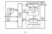
- FIG. 2 is a structural block diagram of a low-latency GMP mapping system based on state machine adaptive control in an embodiment of the present invention.
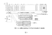
- Figure 3 is Figure 17-16 of Section 17.7.5 in the G.709 standard.
- FIG. 4 is a schematic diagram of fluctuations in the average value of C nD in state 1 in Embodiment 6 of the present invention.
- FIG. 5 is a schematic diagram of fluctuations in the average value of C nD in state 2 in Embodiment 6 of the present invention.
- FIG. 6 is a schematic diagram of fluctuations of an average value of C nD in state 3 in Embodiment 6 of the present invention.
- FIG. 7 is a schematic diagram of fluctuations in the average value of C nD in state 4 in Embodiment 6 of the present invention.
- FIG. 8 is a schematic diagram of fluctuations in the average value of C nD in state 5 in Embodiment 6 of the present invention.
- FIG. 9 is a schematic diagram of a 5-value state machine transition in Embodiment 6 of the present invention.
- Embodiment 1 of the present invention provides a low-latency GMP mapping method based on state machine adaptive control, including the following steps:
- the adaptive control mechanism of the GMP mapping state machine it automatically senses the frequency deviation of services on both sides of the input and output of the GMP mapping, completes the switching of the GMP mapping state, and controls the FIFO (First Input, First Output, FIFO) water level through the FIFO The water level controls the state transition of the GMP mapping state machine.
- FIFO First Input, First Output, FIFO
- the above GMP mapping method specifically includes the following steps:
- the GMP mapping state machine has at least two states. Based on the current state of the GMP mapping state machine, each set of C m , C nD , and ⁇ C nD value sequences corresponding to the next mapping processing cycle is calculated. Each state corresponds to a different actual situation.
- m is the number of bits in each data block on the bearer side
- n is the number of bits in each data block on the client side
- m is 8, 16, 64, 256, or 640
- n is 8 or 1
- C m is the number of client data in m-bit blocks
- C n is the number of client-side n-bit data blocks that need to be carried in a bearer frame period or multi-frame period
- C nD is between C n and m / n * C m_down
- C m_down is the round- down of C m value
- ⁇ C nD value is the sum of the difference between C n and m / n * C m_down ;
- the JC (adjustment control byte) overhead fill m-value verification information and the verification information C m C m values of the sequence of values C, ⁇ C nD value [Sigma] C nD sequence of values and the value [Sigma] C nD Step S3 is international standard practice.
- the biggest advantage of the embodiment of the present invention is that the C m value sequence, the C nD value sequence, and the ⁇ C nD value sequence are directly obtained from the state mapping of the GMP mapping state machine, and will not affect the state transition of the GMP mapping state machine.
- the GMP mapping state machine is responsible for controlling the FIFO water level. No matter how the frequency of the business clock on both sides of the FIFO changes (within the scope of the protocol), the FIFO water level will eventually converge within an expected minimum water level range, so only one pole needs to be set.
- the small depth FIFO completes the cache processing of GMP mapping, ensuring that the delay of GMP mapping processing is sufficiently small.
- the number of client-side n-bit blocks that need to be carried in a bearer frame period or bearer multiframe period is:
- f client is the data bit rate on the client side
- f server is the data bit rate on the bearer side. It should be noted that the data bit rate on the bearer side is greater than the data bit rate on the client side.
- T server is the frame period / multiframe period of the bearer side
- B server is the number of bits per frame period / multiframe period of the bearer side
- C n is the number of client-side n-bit data blocks that need to be carried in one bearer frame period or multiframe period .
- the C n value of each frame must be an integer, and the C n value calculated by (1) must contain decimals. Assuming that the C n calculated by (1) is 100.25, then In the actual GMP mapping process, the C n values of 4 frame periods are averaged to obtain a statistical result of 100.25.
- the C n value sequence of the 4 frame periods can be 100, 100, 100, and 101.
- C n can be an integer, and therefore only a predetermined value C n C n_up, C n_down change between two integers.
- GMP mapping is applied in the field of OTN optical transmission network. Taking M-byte block granularity mapping as an example, formula (1) will be the following form:
- C m must be an integer, and it is stipulated that C m can only be changed between the two integers of C m_up and C m_down .
- C m_up means round up the value of C m
- C m_down means down the value of C m Rounding.
- C nD the number of n-bit blocks remaining on the client side that have not been mapped.
- the total number of n-bit blocks to be mapped on the client side is C n and the number of M-byte blocks is C m .
- C nD the number of C nD
- C nD the value of C nD intuitively reflects the fractional part of the value of C m calculated by formula (4).
- the cumulative number of n-bit blocks that have not yet been mapped is recorded as ⁇ C nD . If the value of ⁇ C nD is greater than or equal to M bytes, the C m of the next frame will increase by 1, that is, One frame will map one M-byte data block and one M-byte padding block.
- the service bearer side In addition to carrying customer-side services, the service bearer side must also carry an overhead field and a padding block for rate adaptation.
- the number of padding blocks in this frame is determined by the C m value of the previous frame, and the position of the padding blocks is determined by the error sum algorithm:
- Equations (9) and (10) are error summation algorithms.
- P server represents the number of M-byte blocks available for mapping in a frame period on the bearer side
- j represents the number of M-byte blocks
- each M word Segments can be loaded with client-side data or can be inserted with all-zero padding.
- the j in formula (9) represents the j-th M byte block filling data
- the j in formula (10) represents the j-th M byte block filling with all zero padding
- the range of j is [1, Pserver].
- each padding block will be evenly distributed in the frame of data.
- each set of C m , C nD , and ⁇ C nD value sequences corresponding to the next mapping processing cycle is calculated, which specifically includes the following steps:
- N_up-N_down 1.
- the GMP mapping processing state machine Since the result of M / C nD will not be an integer, in order to achieve GMP mapping rate matching, the GMP mapping processing state machine will inevitably alternate between 2 states, that is, the GMP mapping processing state machine has 2 states:
- Each GMP mapping state will form a set of corresponding C m value sequences. According to the C m value sequence, a C nD value sequence and a ⁇ C nD value sequence can be skillfully constructed.
- the sequence of C m values corresponding to state 1 is: C nD average for:
- the sequence of C nD values is:
- the sequence of ⁇ C nD values is: Means right Round down, Means right Round up, mod ( ⁇ i C nD (i), M) represents the remainder;
- the sequence of C m values corresponding to state 2 is: C nD average for:
- the sequence of C nD values is:
- the sequence of ⁇ C nD values is:
- i and j represent the serial numbers of the current C nD value in the C nD value sequence.
- the C m value sequence is directly obtained according to the state of the GMP mapping state machine.
- the C nD value sequence needs to be continuously combined and matched between floor (C nD ) and ceiling (C nD ).
- the final C nD value sequence The effect is to represent the average value of C nD , for example: the average value of C nD is 10.25, then the C nD sequence may be: 10, 10, 10, 11; and the ⁇ C nD value sequence needs to be based on the C nD value sequence
- Each C nD value is accumulated (modulus M).
- C nD values in a state processing cycle (such as N_up frame or N_down frame) is an integer multiple of the mapping granularity M, and x 1 and x 2 in Table 1 are the integer multiples, and the integer multiples It is adjustable when constructing the C nD value.
- the above method of constructing the C nD value sequence not only meets the requirements of the GMP mapping protocol, but it is also important to let the ⁇ C nD of the last frame of a state processing cycle be 0 to isolate the ⁇ C between the two states of the GMP mapping state machine.
- the complexity of nD value sequence calculation can maximize the simplification of the design and easily generate ⁇ C nD values without affecting the performance of the GMP mapping process.
- the GMP mapping state machine will automatically switch between state 1 and state 2 according to the change of the water level value, complete the GMP mapping, and make the FIFO water level fluctuate within a certain threshold near the median water level.
- GMP mapping is performed by the above method, and the GMP mapping processing state is only the above two states, and each state will calculate a set of C m value sequence and ⁇ C nD value sequence.
- the GMP mapping state machine will frequently switch between the two states to complete the GMP mapping process.
- the maximum and minimum C nD values can be calculated as follows:
- C n_max represents the maximum value of C n
- C m_max_down represents the minimum value of C m is rounded down
- C n_min represents the minimum value of C n
- C n_min_down represents the minimum value of C n is rounded down
- f client is the client-side data bit rate
- F server is the data bit rate of the bearer side
- B server is the number of bits per frame period / multiframe period on the bearer side.
- the difference between N_up-N_down is uniquely determined by the frequency offset range allowed by the system.
- the GMP mapping processing module considers that it can work normally even when the services on both sides have extreme frequency deviations, so the N_up and N_down values must be calculated according to formulas (15) and (16).
- the GMP mapping state machine can also switch between the two states according to the method shown in Table 1 to implement the entire GMP mapping process. The only difference is that after considering the frequency offset, the values of N_up and N_down are determined by the formulas (15) ⁇ (16), and after considering the frequency offset, the accuracy of the C nD value will also be affected to some extent.
- the GMP mapping state machine can be set to a total of two states, and the corresponding two sets of C m , C nD , and ⁇ C nD sequences are obtained according to the method of Table 1. This state corresponds to different actual frequency deviations.
- the state of the GMP mapping state machine can be further split to make the granularity of the C nD value change smaller.
- the intermediate state (corresponding to the closest ideal without frequency deviation) is selected by default for mapping during initialization.
- Each mapping processing cycle completes the FIFO water level timing sampling and judgment. If the water level When the water level rises, the GMP mapping state machine transitions to an adjacent state with a high mapping rate; if the water level does not change, the GMP mapping state machine maintains the current state; if the water level decreases, the GMP mapping state machine transitions to an adjacent state with a low mapping rate.
- the load-side read rate is greater than the client-side write rate, which reduces the FIFO water level to the threshold
- the read-enable control is used to reduce the data read rate of the load-side to increase the water level appropriately.
- the output rate is less than the write rate on the client side, so that when the FIFO water level rises to the threshold value, the read enable control is used to increase the data read rate on the bearer side, thereby reducing the water level appropriately.
- the GMP mapping state machine will eventually adaptively and stably switch back and forth between two adjacent states, and regardless of the actual frequency offset, the FIFO water level will always be locked near the median water level fluctuation.
- the GMP mapping state machine When there is a frequency deviation, the GMP mapping state machine is decomposed and a new state is inserted.
- the principle of inserting a new state is:
- calculating the C m value sequence, the C nD value sequence, and the ⁇ C nD value sequence of the next mapping processing cycle further including the following steps:
- the number of states of the GMP mapping state machine is calculated according to the following formula:
- y is the minimum value
- the corresponding value of x + y is the smallest.
- C nD (z) represents the z-th C nD value of the C nD sequence.
- the value of z ranges from [1, x], where x is the number of all frames in the state, and delta represents the cumulative error value of each calculation. Value is 0;
- the GMP mapping state machine When there is a frequency offset, the GMP mapping state machine has at least two states, and calculates the corresponding series of C m , C nD , and ⁇ C nD values, and each state corresponds to a different actual frequency offset situation;
- the intermediate state is selected for mapping during initialization, which corresponds to the closest ideal without frequency deviation.
- Each mapping processing cycle completes the FIFO water level timing sampling and judgment. If the water level rises, the GMP mapping The state machine transitions to a neighboring state with a high mapping rate; if the water level does not change, the GMP mapping state machine maintains the current state; if the water level drops, the GMP mapping state machine transitions to a neighboring state with a low mapping rate; the GMP mapping state machine eventually adapts Stably switch back and forth between two adjacent states, and the FIFO water level is locked to fluctuate near the median water level.
- Embodiment 4 of the present invention provides a low-latency GMP mapping system based on adaptive control of a state machine.
- the system includes a state machine adaptive control module for mapping the adaptive control of the state machine according to GMP.
- Mechanism automatically senses the frequency deviation of services on both sides of the input and output of GMP mapping, completes the switching of GMP mapping state and FIFO (First Input First Output) water level control, and controls the state transition of the GMP mapping state machine through the FIFO water level .
- FIFO First Input First Output
- the state machine adaptive control module includes a calculation sub-module, a bearer-side framing sub-module, and a read control sub-module.
- the calculation sub-module is used for: the GMP mapping state machine has at least 2 states, and the state machine adaptive control module includes a calculation sub-module for: calculating the corresponding mapping processing cycle according to the current state of the GMP mapping state machine.
- Each group of C m , C nD , ⁇ C nD value sequence, each state corresponds to a different actual frequency offset situation
- m is the number of bits in each data block on the bearer side
- n is the number of bits in each data block on the client side Number
- m is 8, 16, 64, 256, or 640
- n is 8 or 1
- C m is the number of m-bit block client data
- C n is the number of clients that need to be carried in a frame period or multi-frame period
- the number of side n-bit data blocks, C nD is the difference between C n and m / n * C m_down , C m_down is the rounding down of C m value, and
- Load side framing sub-module for: determining the number of the next frame according to the spacer sequence of values C m C m each, the position filled by the error summing block decision algorithm; in JC (adjustment control byte) overhead Fill in: check information of C m value and C m value in C m value sequence, check information of ⁇ C nD value and ⁇ C nD value in ⁇ C nD value sequence.
- the read control sub-module is used to complete the control of the FIFO read rate according to the C m value.
- Existing GMP mapping scheme generally comprises FIFO write control module, FIFO buffer module, FIFO read control module, C m / C nD / ⁇ C nD calculation module and the load side framing module.
- the embodiment of the present invention utilizes a GMP mapping state machine to adaptively control the FIFO water level, and simultaneously calculates C m , C nD , and ⁇ C nD .
- the calculation submodule is specifically used for:
- the determined C nD value is mapped with the granularity of M byte blocks.
- One frame is inserted for every N frames, and one more data block is inserted compared to the previous N-1 frame.
- the sub-module calculates the value of N as follows:
- M represents the value of m / 8 in C m
- C nD represents the difference between Cn and m / n * C m_down
- the GMP mapping state machine has the following two states:
- the GMP mapping state machine Through the monitoring and control of the FIFO water level, the GMP mapping state machine frequently switches between the two states to complete the GMP mapping: periodically sampling the FIFO water level and judging whether the current GMP mapping state needs to be switched according to the change in the water level value. When the water level is lower than the expected value, it switches from state 2 to state 1.
- Each GMP mapping state forms a set of corresponding C m value sequences. The calculation sub-module is based on the C m value. Sequence to calculate the sequence of C nD and ⁇ C nD values.
- the sequence of C m values corresponding to state 1 is: C nD average for:
- the sequence of C nD values is:
- the sequence of ⁇ C nD values is: Means right Round down, Means right Round up, mod ( ⁇ i C nD (i), M) represents the remainder;
- the sequence of C m values corresponding to state 2 is: C nD average for:
- the sequence of C nD values is:
- the sequence of ⁇ C nD values is:
- i and j represent the serial number of the current C nD value in the C nD value sequence
- the C m value sequence is directly obtained according to the state of the GMP mapping state machine
- the C nD value sequence is between floor (C nD ) and ceiling (C nD ) obtained with the combination between, ⁇ C nD value sequence obtained according to the accumulated value C nD C nD of each value in the sequence
- C nD value N_up N_down frame or frames and mapping granularity is an integral multiple of M, x 1, x 2 It is an integer multiple of adjustable value
- the calculation sub-module When there is no frequency deviation, the calculation sub-module periodically samples the FIFO water level to determine whether the current GMP mapping state needs to be switched.
- the specific process is:
- the GMP mapping state machine will automatically switch between state 1 and state 2 according to the change of the water level value, complete the GMP mapping, and make the FIFO water level fluctuate within a certain threshold near the median water level.
- the frequency deviation allowed by the client-side service is ⁇ ⁇ f c
- the frequency deviation allowed by the bearer-side service is ⁇ ⁇ f s .
- the maximum C nD value C nD_max and the minimum C nD value C nD_min are:
- C n_max represents the maximum value of Cn
- C m_max_down represents the maximum value of C m is rounded down
- C n_min represents the minimum value of Cn
- C n_min_down represents the minimum value of C m is rounded down
- f client is the client-side data bit rate
- f server is the data bit rate on the bearer side
- B server is the number of bits per frame period / multiframe period on the bearer side;
- N_up-N_down 1
- N_up-N_down 1
- N_up-N_down is uniquely determined by the frequency offset range allowed by the system.
- the calculation submodule decomposes the GMP mapping state machine and inserts a new state.
- the principle of inserting a new state is:
- calculating the C m value sequence, the C nD value sequence, and the ⁇ C nD value sequence of the next mapping processing cycle further including the following steps:
- the calculation submodule calculates the number of states of the GMP mapping state machine according to the following formula:
- the calculation submodule calculates the x and y values and the corresponding values in each state according to the following formula
- y is the minimum value
- the corresponding value of x + y is the smallest.
- the calculation sub-module calculates the sequence value of the C nD value as follows:
- C nD (z) represents the z-th C nD value of the C nD sequence.
- the value of z ranges from [1, x], where x is the number of all frames in the state, and delta represents the cumulative error value of each calculation. Value is 0;
- the GMP mapping state machine When there is a frequency offset, the GMP mapping state machine has at least two states, and the corresponding groups of C m , C nD , and ⁇ C nD value sequences are calculated, and each state corresponds to a different actual frequency deviation situation; how many GMP mapping state machines are there? In the two states, the intermediate state is selected for mapping during initialization, corresponding to the closest ideal without frequency deviation. Each mapping processing cycle completes a FIFO water level timing sampling and judgment. If the water level increases, the GMP mapping state machine moves to a higher mapping rate.
- the GMP mapping state machine maintains the current state; if the water level drops, the GMP mapping state machine transitions to a neighboring state with a low mapping rate; the GMP mapping state machine eventually adaptively stabilizes in the adjacent The states are switched back and forth, and the FIFO water level is locked to fluctuate near the median water level.
- a GMP mapping from 100GBASE-R (100GE Ethernet) to OPU4 is used as an example to describe in detail the specific implementation process of a low-latency GMP mapping system based on state machine adaptive control.
- Embodiment 5 of the present invention provides a low-latency GMP mapping system based on state machine adaptive control.
- the system includes a write control module 11, a FIFO buffer module 12, a state machine adaptive control module 13, and a state.
- the machine adaptive control module 13 includes a bearer-side framing sub-module 14, a read control sub-module 15 and a calculation sub-module 16.
- the FIFO write control module 11 is responsible for writing effective data on the client side into the FIFO.
- the FIFO buffer module 12 is configured to buffer client-side data.
- the state machine adaptive control module 13 uses the read control sub-module 15 to complete the adaptive control of the FIFO water level.
- the read-enable control Reduce the rate of reading data on the load side, so that the water level rises appropriately; when the rate of read on the load side is less than the write rate on the client side, so that the FIFO water level rises to the threshold value, the load is improved through read enable control The rate of reading data from the side, so that the water level is appropriately reduced, and finally the FIFO water level is maintained near the expected median water level.
- the bearer-side framing sub-module 14 is responsible for framing the bearer-side data, including C m , ⁇ C nD coding, and insertion.
- the read control sub-module 15 completes the control of the FIFO read rate according to the C m value.
- the calculation sub-module 16 calculates the C m / C nD / ⁇ C nD value by using the real-time state of the GMP mapping state machine, and feeds back the C m value to the read control sub-module 15.
- the 189 in the C m value sequence can also be at any of the previous positions, but the C nD value sequence must be changed accordingly. From the perspective of convenience, placing 189 at the rear is the most Ok.
- the process of calculating the C nD value sequence value through the calculation submodule is: :
- the process of calculating the C nD value sequence value through the calculation submodule is:
- C nD_min , C nD_max , N_up, and N_down are obtained as follows:
- the GMP mapping process can be completed. Comparing the C nD value sequences in Table 4 and Table 3, it can be found that after considering the frequency offset, the fluctuation range of the C nD value becomes larger, and the corresponding C nD values are 11.429 to 13.333 and 10.000 to 16.000, so it can be said that : ⁇ C nD (C nD value fluctuation range) increased from 1.9 to 6. C nD changes in a wide range, which will affect the quality of client-side clock recovery to a certain extent.
- Table 5 shows the calculation results of the five-value state machine GMP parameters after inserting the new state. There are five states in total. After the GMP mapping is stable, depending on the actual frequency offset, the GMP mapping state machine will only adapt to an adjacent two Between states.
- the number of frames in the above 5 states: 8, 7, 13, 6, and 11 are calculated from the C nD average value of 10 to 14.545, and the maximum and minimum values of the C nD value are calculated when there is a frequency deviation. , Such as 14.131 and 10.518, then you need to take several states separately: 10, 11, 12, 13, 14, 15 and then calculate the C m value sequence by inverse push. At this time, you can calculate the state processing cycle. .
- W is a non-zero natural number, from 1 to the number of states
- C nD (z) represents the z-th C nD value of the C nD sequence.
- the value of z ranges from [1, x], where x is the number of all frames in the state, and delta represents the cumulative error value of each calculation. Value is 0;
- the five states of the GMP mapping state machine are represented as S101, S102, S103, S104, and S105, respectively.
- the GMP mapping processing cycle of each state and the C m , C nD , and ⁇ C nD value sequences corresponding to the processing cycle are shown in state 1 to state 5 of Table 5, respectively.
- the GMP mapping state machine operates as follows:
- the GMP mapping state machine is in the waiting state. As the client-side data is continuously written into the FIFO, the FIFO water level rises. After the FIFO water level reaches the median water level, the GMP mapping state machine enters the S103 state.
- the GMP mapping state machine After the GMP mapping state machine enters the S103 state, the FIFO water level is sampled each time in the last clock cycle of the 13th frame. If the water level rises relative to the median water level, the GMP mapping state machine enters the S104 state.
- the GMP mapping state machine After the GMP mapping state machine enters the S103 state, the FIFO water level is sampled each time in the last clock cycle of the 13th frame. If the water level is lowered relative to the median water level, the GMP mapping state machine enters the S102 state.
- the GMP mapping state machine After the GMP mapping state machine enters the S103 state, the FIFO water level is sampled every last clock cycle of the 13th frame. If the water level does not change from the median level, the GMP mapping state machine maintains the S103 state.
- the GMP mapping state machine After the GMP mapping state machine enters the S103 state, if the FIFO is empty or full, the GMP mapping state machine resets and enters the waiting state.
- the GMP mapping state machine After the GMP mapping state machine enters the S104 state, the FIFO water level is sampled every last clock cycle of the sixth frame. If the water level rises relative to the median water level, the GMP mapping state machine enters the S105 state.
- the GMP mapping state machine After the GMP mapping state machine enters the S104 state, each time the FIFO water level is sampled in the last clock cycle of the 6th frame. If the water level decreases relative to the median water level, the GMP mapping state machine enters the S103 state.
- the GMP mapping state machine After the GMP mapping state machine enters the S104 state, the FIFO water level is sampled every last clock cycle of the 6th frame. If the water level does not change from the median level, the GMP mapping state machine maintains the S104 state.
- the GMP mapping state machine After the GMP mapping state machine enters the S104 state, if the FIFO is empty or full, the GMP mapping state machine resets and enters the start waiting state.
- the GMP mapping state machine After the GMP mapping state machine enters the S102 state, the FIFO water level is sampled every last clock cycle of the seventh frame. If the water level rises relative to the median water level, the GMP mapping state machine enters the S103 state.
- the GMP mapping state machine After the GMP mapping state machine enters the S102 state, each time the FIFO water level is sampled in the last clock cycle of the seventh frame. If the water level decreases relative to the median water level, the GMP mapping state machine enters the S101 state.
- the GMP mapping state machine After the GMP mapping state machine enters the S102 state, the FIFO water level is sampled every last clock cycle of the seventh frame. If the water level does not change from the median level, the GMP mapping state machine maintains the S102 state.
- the GMP mapping state machine After the GMP mapping state machine enters the S102 state, if the FIFO is empty or full, the GMP mapping state machine resets and enters the waiting state.
- the GMP mapping state machine After the GMP mapping state machine enters the S105 state, the FIFO water level is sampled every last clock cycle of the 11th frame. If the water level rises relative to the median water level, the GMP mapping state machine maintains the S105 state.
- the GMP mapping state machine After the GMP mapping state machine enters the S105 state, each time the FIFO water level is sampled in the last clock cycle of the 11th frame. If the water level is lowered relative to the median water level, the GMP mapping state machine enters the S104 state.
- the GMP mapping state machine After the GMP mapping state machine enters the S105 state, the FIFO water level is sampled every last clock cycle of the 11th frame. If the water level does not change from the median level, the GMP mapping state machine maintains the S105 state.
- the GMP mapping state machine After the GMP mapping state machine enters the S105 state, if the FIFO is empty or full, the GMP mapping state machine resets and enters the waiting state.
- the GMP mapping state machine After the GMP mapping state machine enters the S101 state, the FIFO water level is sampled every last clock cycle of the eighth frame. If the water level rises relative to the median water level, the GMP mapping state machine enters the S102 state.
- the GMP mapping state machine After the GMP mapping state machine enters the S101 state, each time the FIFO water level is sampled in the last clock cycle of the eighth frame. If the water level is lowered relative to the median water level, the GMP mapping state machine maintains the S101 state.
- the GMP mapping state machine After the GMP mapping state machine enters the S101 state, the FIFO water level is sampled every last clock cycle of the eighth frame. If the water level does not change from the median level, the GMP mapping state machine maintains the S101 state.
- the GMP mapping state machine After the GMP mapping state machine enters the S101 state, if the FIFO is empty or full, the GMP mapping state machine resets and enters the start waiting state.
- the GMP mapping state machine After the GMP mapping is completed through the above process, after stabilization, depending on the actual frequency offset, the GMP mapping state machine will inevitably switch back and forth between two adjacent states, but the FIFO water level is always locked near the median water level. It has nothing to do with frequency offset. Therefore, you only need to set a small value for the FIFO buffer depth to complete the GMP mapping, which fully reduces the cache delay.
Landscapes
- Engineering & Computer Science (AREA)
- Computer Networks & Wireless Communication (AREA)
- Signal Processing (AREA)
- Quality & Reliability (AREA)
- Theoretical Computer Science (AREA)
- Physics & Mathematics (AREA)
- General Engineering & Computer Science (AREA)
- General Physics & Mathematics (AREA)
- Data Exchanges In Wide-Area Networks (AREA)
- Mobile Radio Communication Systems (AREA)
Abstract
本发明公开了一种基于状态机自适应控制的低时延GMP映射方法及系统,涉及GMP映射领域。该方法包括以下步骤:根据GMP映射状态机的自适应机制,自动感知GMP映射的输入和输出两侧业务频偏情况,完成GMP映射状态的切换和FIFO水位控制。本发明能最小化FIFO的深度,最大限度满足低时延性能。
Description
本发明涉及GMP映射领域,具体是涉及一种基于状态机自适应控制的低时延GMP映射方法及系统。
近年来,人们对移动通信需求的不断增长,推动着移动互联网技术的飞速发展。移动网络进入4G时代后,虽在用户接入速率上较3G网络而言有了本质的提升,但人们对更高性能移动通信的追求从未停止。为了应对未来爆炸性的移动数据流量增长、海量的设备连接、不断涌现的各类新业务和应用场景,第五代移动通信(5G)系统应运而生。
未来5G网络,不仅对数据接入速率有更高的要求,同时也对时延提出了“无感知”的苛刻要求。5G网络对端到端提出了毫秒级的时延要求。端到端时延包含接入网时延和传输网时延,OTN(Optical Transport Network,光传送网)传输网时延又分为信息传送时延和设备内部处理时延,而OTN设备处理时延主要包含FEC(Forward Error Correction,前向纠错)编译码时延和数据流映射处理时延等。
在OTN光传送网各种业务颗粒映射场景中,GMP(Generic Mapping Procedure,通用映射规程)映射被广泛采用。GMP映射是一种通用异步映射规程,主要通过插入填充字节,完成异步数据流的转换。按照OTN G.709协议,GMP异步映射既可在OTN网络内部实现低速OTN业务流到高速OTN业务流的汇聚,也可以完成对OTN网络外部固定比特速率客户信号的承载,即通过GMP映射实现CBR(Constant Bit Rate,固定码率)Over OTN。由此可见,GMP映射为OTN光传送网的一项核心技术,GMP映射技术的性能指标(例如时延 特性)将会直接影响OTN网络的相关性能。按照协议规定的GMP映射方法,实现GMP映射有多种方案,不同方案带来的处理延时会有较大的差别。
OTN光传送网中实现GMP映射,主要涉及如何实时计算C
m(number of m-bit Client data entities,m比特块客户数据个数)、C
nD值、ΣC
nD值以及对填充块的插入控制,m为承载侧每个数据块中的比特数,n为客户侧每个数据块中的比特数,参见G.709标准17.7节第100页,m取值为8、16、64、256或640,n取值为8或1,C
nD表示C
n与m/n*C
m_down之间的差值(difference between Cn and(m/n*C
m)),C
m为m比特块客户数据个数,C
m_up表示对C
m值向上取整,C
m_down表示对C
m值向下取整,C
n为一个承载帧周期或者复帧周期需要承载的客户侧n比特数据块的数量;ΣC
nD值表示C
n与m/n*C
m_down之间的差值求和。本帧的C
m值决定了下一帧是否插入以及插入多少填充块,插入填充块的具体位置则由误差求和算法的固定规律决定;收端利用上一帧的C
m值,剥离出当前帧中的所有填充块,并将当前帧承载的客户侧数据解下来,然后利用接收的ΣC
nD值的统计规律得出精确的C
nD值,利用C
nD可以精确恢复出客户侧业务时钟。GMP映射的核心就是如何准确实时计算C
m、C
nD、ΣC
nD的值。计算C
m、C
nD、ΣC
nD值有多种方法,不同方法带来的时延有较大的差别。急需一种全新的计算C
m、C
nD、ΣC
nD的方法,最大限度满足低时延性能。
发明内容
本发明的目的是为了最大限度满足低时延性能,提供一种基于状态机自适应控制的低时延GMP映射方法及系统,能够最小化FIFO的深度,最大限度满足低时延性能。
第一方面,提供一种基于状态机自适应控制的低时延GMP映射方法,包括以下步骤:
根据GMP映射状态机的自适应控制机制,自动感知GMP映射的输入和输出两侧业务频偏情况,完成GMP映射状态的切换和FIFO水位控制,通过FIFO 水位控制GMP映射状态机的状态转移。
根据第一方面,在第一方面的第一种可能的实现方式中,该方法具体包括以下步骤:
GMP映射状态机至少有2种状态,根据GMP映射状态机的当前状态,计算下一个映射处理周期对应的各组C
m、C
nD、ΣC
nD值序列,每种状态对应不同的实际频偏情况,m为承载侧每个数据块中的比特数,n为客户侧每个数据块中的比特数,m取值为8、16、64、256或640,n取值为8或1,C
m为m比特块客户数据个数,C
n为一个承载帧周期或者复帧周期需要承载的客户侧n比特数据块的数量,C
nD为C
n与m/n*C
m_down之间的差值,C
m_down为对C
m值向下取整,ΣC
nD值为C
n与m/n*C
m_down之间的差值求和。
根据第一方面的第一种可能的实现方式,在第一方面的第二种可能的实现方式中,该方法具体包括以下步骤:
无频偏时,GMP映射状态机有2种状态,以M字节块的颗粒度进行映射,每N帧有1帧相对前N-1帧多插入一个数据块,少一个填充块,按下式计算N值:

M表示C
m中的m/8取值,
 表示对
表示对
 向上取整,
向上取整,
 表示对
表示对
 向下取整,N
_up表示对
向下取整,N
_up表示对
 向上取整后的数值,N
_down表示对
向上取整后的数值,N
_down表示对
 向下取整后的数值。
根据第一方面的第二种可能的实现方式,在第一方面的第三种可能的实现方式中,该方法还包括以下步骤:
无频偏时,GMP映射状态机有以下2种状态:
状态1:每N_up帧有1帧以C
m=C
m_up进行映射,其他帧以C
m=C
m_down进行映射,C
m_up表示对C
m值向上取整;状态1对应的C
m值序列为:
 C
nD平均值
C
nD平均值
 为:
为:

状态2:每N_down帧有1帧以C
m=C
m_up进行映射,其他帧以C
m=C
m_down进行映射;状态2对应的C
m值序列为:
 C
nD平均值
C
nD平均值
 为:
为:

每种GMP映射状态形成一组对应的C
m值序列,依据C
m值序列,计算C
nD值序列、ΣC
nD值序列。
根据第一方面的第三种可能的实现方式,在第一方面的第四种可能的实现方式中,该方法还包括以下步骤:
无频偏时,定时采样FIFO水位,判断当前GMP映射状态是否需要切换,具体过程为:
当承载侧读出的速率大于客户侧写入速率,使得FIFO水位降低达到门限值时,由状态2切换到状态1,通过读使能控制,降低承载侧读出数据的速率,从而使水位适当升高;
当承载侧读出的速率小于客户侧写入速率,使得FIFO水位升高达到门限值时,由状态1切换到状态2,通过读使能控制,提高承载侧读出数据的速率,从而使水位适当降低;
GMP映射状态机根据水位值的变化,在状态1、状态2两种状态之间自动切换,完成GMP映射,并使得FIFO水位在中值水位附近一定门限值内波动。
根据第一方面的第一种可能的实现方式,在第一方面的第五种可能的实现方式中,该方法具体包括以下步骤:
有频偏时,对GMP映射状态机进行分解,并插入新状态,插入新状态的原则是:
使任意相邻的状态之间C
nD序列变化不超过2;
下边界状态:
 小于C
nD的最小值C
nD_min;
小于C
nD的最小值C
nD_min;
上边界状态:
 大于C
nD的最大值C
nD_max;
大于C
nD的最大值C
nD_max;
每个状态的最后一帧ΣC
nD=0。
根据第一方面的第五种可能的实现方式,在第一方面的第六种可能的实现方式中,该方法还包括以下步骤:
有频偏时,GMP映射状态机有多于2种状态,根据以下公式计算GMP映射状态机的状态个数:
先计算C
nD_max和C
nD_min,GMP映射状态机的状态个数=floor(C
nD_max)-floor(C
nD_min)+1,floor表示向下取整。
根据第一方面的第六种可能的实现方式,在第一方面的第七种可能的实现方式中,该方法还包括以下步骤:
有频偏时,每种GMP映射状态形成一组对应的C
m值序列,各个状态中假设每x帧有y帧以C
m=C
m_up进行映射,其他帧以C
m=C
m_down映射,根据以下公式计算每个状态中的x和y值及对应的C
nD平均值

状态W:满足floor(C
nD_min)+(W-1)<=M*y/x<=floor(C
nD_min)+W与x+y求和最小的x、y取值,W为非零自然数,取值从1到状态个数,x和y为非零自然数,此时对应的
 即M*y/(floor(C
nD_min)+W)<=x<=M*y/(floor(C
nD_min)+W-1),y取最小值时,对应的x+y的值最小;
即M*y/(floor(C
nD_min)+W)<=x<=M*y/(floor(C
nD_min)+W-1),y取最小值时,对应的x+y的值最小;
依据C
m值序列,计算C
nD值序列、ΣC
nD值序列。
根据第一方面的第七种可能的实现方式,在第一方面的第八种可能的实现方式中,该方法还包括以下步骤:
有频偏时,GMP映射状态机有多于2种状态,初始化时选择中间状态进行映射,对应最接近理想无频偏情况,每个映射处理周期完成一次FIFO水位定时采样和判断,如果水位升高,GMP映射状态机往映射速率高的相邻状态转移;如果水位不变,GMP映射状态机维持当前状态;如果水位下降,GMP映射状态机往映射速率低的相邻状态转移;GMP映射状态机最终自适应稳定在相邻的两个状态之间来回切换,FIFO水位锁定在中值水位附近波动。
根据第一方面的第三种可能的实现方式或者第一方面的第七种可能的实现方式,在第一方面的第九种可能的实现方式中,该方法还包括以下步骤:
无频偏和有频偏两种情况下,C
nD值序列值的计算过程均为:
C
nD(z)表示C
nD序列的第z个C
nD值,z取值范围为[1,x],x为状态中所有帧的个数,delta为每次计算的误差累计值,delta初值为0;
若
 ceiling表示向上取整,则
 floor表示向下取整,
 否则
否则


根据第一方面的第一种可能的实现方式,在第一方面的第十种可能的实现方式中,该方法还包括以下步骤:
根据C
m值序列中的每一个C
m值决定下一帧填充块的数量,填充块的位置由误差求和算法决定;
在调整控制字节JC开销中填入C
m值序列中的C
m值及C
m值的校验信息、ΣC
nD值序列中的ΣC
nD值及ΣC
nD值的校验信息。
第二方面,提供一种基于状态机自适应控制的低时延GMP映射系统,包括状态机自适应控制模块,用于:根据GMP映射状态机的自适应控制机制,自动感知GMP映射的输入和输出两侧业务频偏情况,完成GMP映射状态的切换和FIFO水位控制,通过FIFO水位控制GMP映射状态机的状态转移。
根据第二方面,在第二方面的第一种可能的实现方式中,所述GMP映射状态机至少有2种状态,所述状态机自适应控制模块包括计算子模块,用于:根据GMP映射状态机的当前状态,计算下一个映射处理周期对应的各组C
m、C
nD、∑C
nD值序列,每种状态对应不同的实际频偏情况,m为承载侧每个数据块中的比特数,n为客户侧每个数据块中的比特数,m取值为8、16、64、256或640,n取值为8或1,C
m为m比特块客户数据个数,C
n为一个承载帧周期或者复帧周期需要承载的客户侧n比特数据块的数量,C
nD为C
n与m/n*C
m_down之间 的差值,C
m_down为对C
m值向下取整,ΣC
nD值为C
n与m/n*C
m_down之间的差值求和。
与现有技术相比,本发明的优点如下:
本发明着眼于未来5G网络低时延的要求,提出一种GMP映射方案,映射处理时延接近理论上的最低值。本发明基于状态机自适应控制机制,不论GMP映射状态机的状态数有多少,根据实际频偏大小,GMP映射状态机会自动稳定在相邻的两个状态来回切换,最终实现GMP映射过程。本发明利用FIFO水位控制GMP映射状态机的状态转移,利用GMP映射状态机的状态计算C
m、C
nD、ΣC
nD值序列,从而确保了整个GMP映射的自适应控制过程。由于GMP映射的自适应特性,不论频偏如何变化,稳定后FIFO水位在中值水位附近极小范围内波动,因此能够最小化FIFO的深度,最大限度满足低时延性能。
图1为本发明实施例中基于状态机自适应控制的低时延GMP映射方法的流程图。
图2为本发明实施例中基于状态机自适应控制的低时延GMP映射系统的结构框图。
图3为G.709标准中章节17.7.5的Figure17-16。
图4为本发明实施例6中状态1的C
nD平均值的波动示意图。
图5为本发明实施例6中状态2的C
nD平均值的波动示意图。
图6为本发明实施例6中状态3的C
nD平均值的波动示意图。
图7为本发明实施例6中状态4的C
nD平均值的波动示意图。
图8为本发明实施例6中状态5的C
nD平均值的波动示意图。
图9为本发明实施例6中5值状态机转移的示意图。
下面结合附图及具体实施例对本发明作进一步的详细描述。
实施例1
本发明实施例1提供一种基于状态机自适应控制的低时延GMP映射方法,包括以下步骤:
根据GMP映射状态机的自适应控制机制,自动感知GMP映射的输入和输出两侧业务频偏情况,完成GMP映射状态的切换和FIFO(First Input First Output,先入先出队列)水位控制,通过FIFO水位控制GMP映射状态机的状态转移。
参见图1所示,上述GMP映射方法具体包括以下步骤:
S1、GMP映射状态机至少有2种状态,根据GMP映射状态机的当前状态,计算下一个映射处理周期对应的各组C
m、C
nD、∑C
nD值序列,每种状态对应不同的实际频偏情况,m为承载侧每个数据块中的比特数,n为客户侧每个数据块中的比特数,m取值为8、16、64、256或640,n取值为8或1,C
m为m比特块客户数据个数,C
n为一个承载帧周期或者复帧周期需要承载的客户侧n比特数据块的数量,C
nD为C
n与m/n*C
m_down之间的差值,C
m_down为对C
m值向下取整,ΣC
nD值为C
n与m/n*C
m_down之间的差值求和;
S2、根据C
m值序列中的每一个C
m值决定下一帧填充块的数量,填充块的位置由误差求和算法决定;
S3、在JC(调整控制字节)开销中填入:C
m值序列中的C
m值及C
m值的校验信息、ΣC
nD值序列中的ΣC
nD值及ΣC
nD值的校验信息,步骤S3是国际标准做法。
本发明实施例最大的优点是:C
m值序列、C
nD值序列、ΣC
nD值序列直接从GMP映射状态机的状态映射得到,不会对GMP映射状态机的状态转移造成影响。GMP映射状态机负责控制FIFO水位,不论FIFO两侧业务时钟频偏如何变化(在协议规定范围内),最终都会让FIFO水位收敛在一个预期的极小的水位区间内,从而只需设置一个极小深度的FIFO完成GMP映射的缓存处理,保证 了GMP映射处理的时延足够小。
下面先描述GMP映射的基本原理,然后在此基础之上具体描述具有低时延GMP映射的技术方案。
对于任何给定的固定比特速率的客户侧信号,在一个承载帧周期或者承载复帧周期内,需要承载的客户侧n比特块的数量为:

f
client为客户侧数据比特速率,f
server为承载侧数据比特速率,需要注意的是:承载侧的数据比特速率>客户侧的数据比特速率。
T
server为承载侧帧周期/复帧周期,B
server为承载侧一个帧周期/复帧周期的比特数,C
n为一个承载帧周期或者复帧周期需要承载的客户侧n比特数据块的数量。
由于在实际GMP映射过程中,每一帧的C
n值必须是一个整数,而(1)式计算的C
n值必然含小数,假设按照(1)式计算得到的C
n为100.25,那么在实际GMP映射过程中,将会通过4个帧周期的C
n值平均,得到100.25的统计结果,这4个帧周期的C
n值序列可以是100、100、100、101。
由于实际的C
n只能是整数,因此规定C
n值只能在C
n_up、C
n_down两个整数之间变化。


将GMP映射应用在OTN光传送网领域,以M字节块颗粒度的映射为例,(1)式将会是以下形式:

同理,C
m值也必须是整数,并且规定C
m只能在C
m_up、C
m_down两个整数之间变化,C
m_up表示对C
m值向上取整,C
m_down表示对C
m值向下取整。


C
m和C
n的区别仅仅在于GMP映射处理的颗粒度变大了。
定义一次GMP映射之后,客户侧剩余没有映射完的n比特块的数量为C
nD,C
nD具有以下表达形式:

C
nD值的物理意义可以这么理解:
在一个承载帧周期内,客户侧总共需要映射的n比特块的数量为C
n,M字节块的数量为C
m,按照C
m值映射完后,还剩余的没有映射完的n比特块的数量即为C
nD,C
nD值直观的反应了(4)式计算得到的C
m值的小数部分。
当进行多个帧周期的GMP映射后,累积还未映射完的n比特块数量记为ΣC
nD,如果ΣC
nD值大于等于M字节,那么下一帧的C
m将会增加1,即下一帧将会多映射一个M字节的数据块,少一个M字节的填充块。
ΣC
nD的取值范围为:
0≤∑C
nD≤M-1(n=8) (8)
业务承载侧除了承载客户侧业务外,还必须携带开销字段以及用于速率适配的填充块。本帧填充块的数量由上一帧的C
m值决定,填充块的位置由误差求和算法决定:
数据:if(j×C
n)mod P
server<C
n(n=640) (9)
填充:if(j×C
n)mod P
server≥C
n(n=640) (10)
公式(9)(10)就是误差求和算法,上式中,P
server代表承载侧一个帧周期内可供映射的M字节块的数量,j代表M字节块的编号,每个M字节块可以装载客户侧数据,也可以插入全零填充。公式(9)中的j表示第j个M字节块填数据,公式(10)中的j表示第j个M字节块填全零填充,j的范围是[1,Pserver]。
按照以上原则,当一帧数据需插入多个填充块时,各填充块在本帧数据中 将会是均匀分布的。
以上(1)~(10)式完整描述了GMP映射中计算C
m、C
nD、ΣC
nD的基本公式以及数据块和填充块分布的基本算法。按照GMP映射原理,计算C
m、C
nD、ΣC
nD是有多种方法的,为了找到一种具有低时延特性的GMP映射处理机制,需要进一步分析。
实施例2
在实施例1的基础上,根据GMP映射状态机的当前状态,计算下一个映射处理周期对应的各组C
m、C
nD、ΣC
nD值序列,具体包括以下步骤:
在理想无频偏的情况下,对于一个确定的C
nD值(小数),以M字节块的颗粒度进行GMP映射,那么每N帧必将有1帧相对前N-1帧会多插入一个数据块,少一个填充块,其中N值按下式计算:


其中,N_up-N_down=1。
M表示C
m中的m/8取值(ITU-T G.709附录D.2章节规定:M=m/8),C
nD表示Cn与m/n*C
m_down之间的差值,
 表示对
表示对
 向上取整,
向上取整,
 表示对
表示对
 向下取整,N
-up表示对
向下取整,N
-up表示对
 向上取整后的数值,N
_down表示对
向上取整后的数值,N
_down表示对
 向下取整后的数值。
上述(11)和(12)式的物理意义是:
由于M/C
nD的结果并不会是整数,为了实现GMP映射速率匹配,GMP映射处理状态机必然会在2种状态之间交替,也即GMP映射处理状态机有2种状态:
状态1是:每N_up帧中有1帧以C
m=C
m_up进行映射,其他N_up-1帧以 C
m=C
m_down进行映射,C
m_up表示对C
m值向上取整,C
m_down表示对C
m值向下取整;
状态2是:每N_down帧中有1帧以C
m=C
m_up进行映射,其他N_down-1帧以C
m=C
m_down进行映射。
通过定时采样FIFO水位,根据FIFO水位值的变化,判断当前GMP映射状态是否需要切换,当FIFO水位超过预期值时,需由状态1切换到状态2;当FIFO水位低于预期值时,需由状态2切换到状态1。每种GMP映射状态都会形成一组对应的C
m值序列,依据该C
m值序列,可巧妙构造出C
nD值序列、ΣC
nD值序列。
按照上述(11)~(12)式对应的两个状态,构造得到的C
m、C
nD、ΣC
nD序列如下表:
表1、GMP映射状态机状态与C
m、C
nD、ΣC
nD序列的关系

状态1对应的C
m值序列为:
 C
nD平均值
C
nD平均值
 为:
为:
 C
nD值序列为:
C
nD值序列为:
 ΣC
nD值序列为:
ΣC
nD值序列为:

 表示对
表示对
 向下取整,
向下取整,
 表示对
表示对
 向上取整,mod(∑
iC
nD(i),M)表示求余;
向上取整,mod(∑
iC
nD(i),M)表示求余;
状态2对应的C
m值序列为:
 C
nD平均值
C
nD平均值
 为:
为:
 C
nD值序列为:
C
nD值序列为:
 ΣC
nD值序列为:
ΣC
nD值序列为:

表1中,i、j表示当前C
nD值在C
nD值序列中的序号。
表1中,C
m值序列是直接根据GMP映射状态机的状态获知的,C
nD值序列需要在floor(C
nD)和ceiling(C
nD)之间不断组合搭配得到,C
nD值序列最终的效果是要表示为C
nD的平均值,例如:C
nD的平均值是10.25,那么C
nD序列就可能是:10、10、10、11;而ΣC
nD值序列则需根据C
nD值序列中的各C
nD值累加(模M)得到。
这里在构造C
nD序列时,需要满足的一个条件是:
一个状态处理周期(例如N_up帧或者N_down帧)内的C
nD值之和是映射颗粒度M的整数倍,表1中的x
1、x
2即为该整数倍的数值,该整数倍的数值在构造C
nD值时是可调节的。
这样构造的C
nD值序列生成∑C
nD值序列时,∑C
nD值序列的最后一个∑C
nD值必然为0,代表∑C
nD向C
m值有进位,所以,∑C
nD=0对应的C
m值也必然会比上一帧的C
m值大1,如表1所示。
上述C
nD值序列的构造方法不仅满足GMP映射协议的要求,另外重要一点,让一个状态处理周期的最后一帧的∑C
nD为0,可以隔离GMP映射状态机的两个状态之间∑C
nD值序列计算的复杂度,可以最大化简化设计,易于生成∑C
nD值,同时又不会对GMP映射处理的性能带来影响。
无频偏时,定时采样FIFO水位,判断当前GMP映射状态是否需要切换,具体过程为:
①当承载侧读出的速率大于客户侧写入速率,使得FIFO水位降低达到门限值时,由状态2切换到状态1,通过读使能控制,降低承载侧读出数据的速率,从而使水位适当升高;
②当承载侧读出的速率小于客户侧写入速率,使得FIFO水位升高达到门限值时,由状态1切换到状态2,通过读使能控制,提高承载侧读出数据的速率,从而使水位适当降低。
GMP映射状态机将根据水位值的变化,在状态1、状态2两种状态之间自动切换,完成GMP映射,并使得FIFO水位在中值水位附近一定门限值内波动。
综上所述,对于C
nD值为确定值的情况,以上述方法进行GMP映射,GMP映射处理状态只有上述两种状态,每种状态都会计算出一组C
m值序列和ΣC
nD值序列。通过对FIFO水位的监测和控制,GMP映射状态机将会在两种状态之间频繁切换,完成GMP映射过程。
考虑实际情况,由于f
client和f
server均会存在频偏和抖动,(7)计算得到的C
nD值不会是固定的,而是在一个范围内变化。
假设客户侧业务允许的频偏为±Δf
c,承载侧业务允许的频偏为±Δf
s,相应的,可以计算得到最大和最小的C
nD值如下:


C
n_max表示C
n最大值,C
m_max_down表示C
m最大值时向下取整,C
n_min表示C
n最小值,C
n_min_down表示C
n最小值时向下取整,f
client为客户侧数据比特速率,f
server为承载侧数据比特速率,B
server为承载侧一个帧周期/复帧周期的比特数。
考虑频偏的情况,上述(11)~(12)式改为:


考虑频偏后,一般地,N_up-N_down>1。
当两侧数据速率和映射颗粒度确定时,N_up-N_down的差值大小由系统允许的频偏范围唯一确定。
GMP映射处理模块考虑到当两侧业务具有极端频偏的情况下也能正常工作,所以N_up和N_down值就必须按照(15)、(16)式计算。此时GMP映射状态机也可以按照表1所示的方法在两种状态之间切换,实现整个GMP映射过程。唯一不同的地方在于,考虑频偏之后的N_up和N_down值由(15)~(16)式决定,并且考虑了频偏之后,C
nD值精度也会受到一定的影响。
实施例3
在实施例2的基础上,为了提高C
nD值精度,可将GMP映射状态机总共设置2种状态,并按照表1的方法得到对应的2组C
m、C
nD、∑C
nD序列,每种状态对应不同的实际频偏情况。
为了得到更精细的C
nD值,可以将GMP映射状态机的状态进行进一步拆分,使C
nD值变化的颗粒度更小。
当GMP映射状态机有多于2个状态时,初始化时默认情况下选择中间状态(对应最接近理想无频偏情况)进行映射,每个映射处理周期完成一次FIFO水位定时采样和判断,如果水位升高,GMP映射状态机往映射速率高的相邻状态转移;如果水位不变,GMP映射状态机维持当前状态;如果水位下降,GMP映射状态机往映射速率低的相邻状态转移。当承载侧读出的速率大于客户侧写入速率,使得FIFO水位降低达到门限值时,通过读使能控制,降低承载侧读出数据的速率,从而使水位适当升高;当承载侧读出的速率小于客户侧写入速率,使得FIFO水位升高达到门限值时,通过读使能控制,提高承载侧读出数据的速率,从而使水位适当降低。。
不论GMP映射状态机最终有多少个状态,GMP映射状态机最终都会自适应稳定在相邻的两个状态之间来回切换,而且不论实际频偏大小,FIFO水位却始终会锁定在中值水位附近波动。
有频偏时,对GMP映射状态机进行分解,并插入新状态,插入新状态的原则是:
使任意相邻的状态之间C
nD序列变化不超过2;
下边界状态:
 小于C
nD的最小值C
nD_min;
小于C
nD的最小值C
nD_min;
上边界状态:
 大于C
nD的最大值C
nD_max;
大于C
nD的最大值C
nD_max;
每个状态的最后一帧ΣC
nD=0。
根据GMP映射状态机的当前状态,计算下一个映射处理周期的C
m值序列、C
nD值序列、ΣC
nD值序列,还包括以下步骤:
有频偏时,根据以下公式计算GMP映射状态机的状态个数:
先计算C
nD_max和C
nD_min,GMP映射状态机的状态个数=floor(C
nD_max)-floor(C
nD_min)+1,floor表示向下取整;各个状态中假设每x帧有y帧以C
m=C
m_up进行映射,其他帧以C
m=C
m_down映射;
根据以下公式计算每个状态中的x和y值及对应的

状态W:满足floor(C
nD_min)+(W-1)<=M*y/x<=floor(C
nD_min)+W与x+y求和最小的x、y取值,W为非零自然数,取值从1到状态个数,x和y为非零自然数,此时对应的
 即M*y/(floor(C
nD_min)+W)<=x<=M*y/(floor(C
nD_min)+W-1),y取最小值时,对应的x+y的值最小。
即M*y/(floor(C
nD_min)+W)<=x<=M*y/(floor(C
nD_min)+W-1),y取最小值时,对应的x+y的值最小。
无频偏和有频偏两种情况下,C
nD值序列值的计算过程均为:
C
nD(z)表示C
nD序列的第z个C
nD值,z取值范围为[1,x],x为状态中所有帧的个数,delta表示每次计算的误差累计值,delta初值为0;
if
 ceiling表示向上取整,则
 floor表示向下取整,
 否则
否则


有频偏时,GMP映射状态机至少有2种状态,计算出对应的各组C
m、C
nD、∑C
nD值序列,每种状态对应不同的实际频偏情况;
GMP映射状态机有多于2种状态时,初始化时选择中间状态进行映射,对应最接近理想无频偏情况,每个映射处理周期完成一次FIFO水位定时采样和判断,如果水位升高,GMP映射状态机往映射速率高的相邻状态转移;如果水位不变,GMP映射状态机维持当前状态;如果水位下降,GMP映射状态机往映射速率低的相邻状态转移;GMP映射状态机最终自适应稳定在相邻的两个状态之间来回切换,FIFO水位锁定在中值水位附近波动。
实施例4
参见图2所示,本发明实施例4提供一种基于状态机自适应控制的低时延GMP映射系统,该系统包括状态机自适应控制模块,用于:根据GMP映射状态机的自适应控制机制,自动感知GMP映射的输入和输出两侧业务频偏情况,完成GMP映射状态的切换和FIFO(First Input First Output,先入先出队列)水位控制,通过FIFO水位控制GMP映射状态机的状态转移。
状态机自适应控制模块包括计算子模块、承载侧成帧子模块和读控制子模块。
计算子模块用于:所述GMP映射状态机至少有2种状态,所述状态机自适应控制模块包括计算子模块,用于:根据GMP映射状态机的当前状态,计算下一个映射处理周期对应的各组C
m、C
nD、∑C
nD值序列,每种状态对应不同的实际频偏情况,m为承载侧每个数据块中的比特数,n为客户侧每个数据块中的比特数,m取值为8、16、64、256或640,n取值为8或1,C
m为m比特块客户数据个数,C
n为一个承载帧周期或者复帧周期需要承载的客户侧n比特数据块的数量,C
nD为C
n与m/n*C
m_down之间的差值,C
m_down为对C
m值向下取整,ΣC
nD值为C
n与m/n*C
m_down之间的差值求和。
承载侧成帧子模块用于:根据C
m值序列中的每一个C
m决定下一帧填充块的数量,填充块的位置由误差求和算法决定;在JC(调整控制字节)开销中填入:C
m值序列中的C
m值及C
m值的校验信息、ΣC
nD值序列中的ΣC
nD值及ΣC
nD值的 校验信息。
读控制子模块,用于:依据C
m值完成FIFO读速率的控制。
现有的GMP映射方案一般包含FIFO写控制模块、FIFO缓存模块、FIFO读控制模块、C
m/C
nD/ΣC
nD计算模块以及承载侧成帧模块。
本发明实施例利用GMP映射状态机自适应控制FIFO水位,并同时计算C
m、C
nD、ΣC
nD。
计算子模块具体用于:
在无频偏的情况下,对于确定的C
nD值,以M字节块的颗粒度进行映射,每N帧有1帧相对前N-1帧多插入一个数据块,少一个填充块,计算子模块按下式计算N值:

M表示C
m中的m/8取值,C
nD表示Cn与m/n*C
m_down之间的差值,
 表示对
表示对
 向上取整,
向上取整,
 表示对
表示对
 向下取整,N
-up表示对
向下取整,N
-up表示对
 向上取整后的数值,N
-down表示对
向上取整后的数值,N
-down表示对
 向下取整后的数值;
GMP映射状态机有以下2种状态:
状态1:每N_up帧有1帧以C
m=C
m_up进行映射,其他帧以C
m=C
m_down进行映射,C
m_up表示对C
m值向上取整,C
m_down表示对C
m值向下取整;
状态2:每N_down帧有1帧以C
m=C
m_up进行映射,其他帧以C
m=C
m_down进行映射。
通过对FIFO水位的监测和控制,GMP映射状态机在2种状态之间频繁切换,完成GMP映射:定时采样FIFO水位,根据水位值的变化,判断当前GMP映射状态是否需要切换,当水位超过预期值时,由状态1切换到状态2;当水位低于预期值时,由状态2切换到状态1,每种GMP映射状态形成一组对应的C
m值序列,计算子模块依据该C
m值序列,计算出C
nD、∑C
nD值序列。
状态1对应的C
m值序列为:
 C
nD平均值
C
nD平均值
 为:
为:
 C
nD值序列为:
C
nD值序列为:
 ΣC
nD值序列为:
ΣC
nD值序列为:

 表示对
表示对
 向下取整,
向下取整,
 表示对
表示对
 向上取整,mod(Σ
iC
nD(i),M)表示求余;
向上取整,mod(Σ
iC
nD(i),M)表示求余;
状态2对应的C
m值序列为:
 C
nD平均值
C
nD平均值
 为:
为:
 C
nD值序列为:
C
nD值序列为:
 ΣC
nD值序列为:
ΣC
nD值序列为:

其中,i、j表示当前C
nD值在C
nD值序列中的序号,C
m值序列根据GMP映射状态机的状态直接得到,C
nD值序列在floor(C
nD)和ceiling(C
nD)之间组合搭配得到,∑C
nD值序列根据C
nD值序列中的各C
nD值累加得到;N_up帧或者N_down帧内的C
nD值之和是映射颗粒度M的整数倍,x
1、x
2为可调节的整数倍数值;C
nD值序列生成∑C
nD值序列时,∑C
nD值序列的最后一个∑C
nD值为0,代表∑C
nD向C
m值有进位,∑C
nD=0对应的C
m值比上一帧的C
m值大1。
无频偏时,计算子模块定时采样FIFO水位,判断当前GMP映射状态是否需要切换,具体过程为:
①当承载侧读出的速率大于客户侧写入速率,使得FIFO水位降低达到门限值时,由状态2切换到状态1,通过读使能控制,降低承载侧读出数据的速率,从而使水位适当升高;
②当承载侧读出的速率小于客户侧写入速率,使得FIFO水位升高达到门限值时,由状态1切换到状态2,通过读使能控制,提高承载侧读出数据的速率,从而使水位适当降低。
GMP映射状态机将根据水位值的变化,在状态1、状态2两种状态之间自动切换,完成GMP映射,并使得FIFO水位在中值水位附近一定门限值内波动。
考虑到频偏时,客户侧业务允许的频偏为±Δf
c,承载侧业务允许的频偏为 ±Δf
s,最大的C
nD值C
nD_max和最小的C
nD值C
nD_min分别为:


C
n_max表示Cn最大值,C
m_max_down表示C
m最大值时向下取整,C
n_min表示Cn最小值,C
n_min_down表示C
m最小值时向下取整,f
client为客户侧数据比特速率,f
server为承载侧数据比特速率,B
server为承载侧一个帧周期/复帧周期的比特数;
考虑到频偏时,
 N_up-N_down>1,当两侧数据速率和映射颗粒度确定时,N_up-N_down由系统允许的频偏范围唯一确定。
有频偏时,计算子模块对GMP映射状态机进行分解,并插入新状态,插入新状态的原则是:
使任意相邻的状态之间C
nD序列变化不超过2;
下边界状态:
 小于C
nD的最小值C
nD_min;
小于C
nD的最小值C
nD_min;
上边界状态:
 大于C
nD的最大值C
nD_max;
大于C
nD的最大值C
nD_max;
每个状态的最后一帧∑C
nD=0。
根据GMP映射状态机的当前状态,计算下一个映射处理周期的C
m值序列、C
nD值序列、ΣC
nD值序列,还包括以下步骤:
有频偏时,计算子模块根据以下公式计算GMP映射状态机的状态个数:
先计算C
nD_max和C
nD_min,GMP映射状态机的状态个数=floor(C
nD_max)-floor(C
nD_min)+1,floor表示向下取整;各个状态中假设每x帧有y帧以C
m=C
m_up进行映射,其他帧以C
m=C
m_down映射;
计算子模块根据以下公式计算每个状态中的x和y值及对应的

状态W:满足floor(C
nD_min)+(W-1)<=M*y/x<=floor(C
nD_min)+W与x+y求和最小的x、y取值,W为非零自然数,取值从1到状态个数,x和y为非零自然数,此时对应的
 即M*y/(floor(C
nD_min)+W)<=x<=M*y/(floor(C
nD_min)+W-1),y取最小值时,对应的x+y的值最小。
即M*y/(floor(C
nD_min)+W)<=x<=M*y/(floor(C
nD_min)+W-1),y取最小值时,对应的x+y的值最小。
无频偏和有频偏两种情况下,计算子模块计算C
nD值序列值的过程均为:
C
nD(z)表示C
nD序列的第z个C
nD值,z取值范围为[1,x],x为状态中所有帧的个数,delta表示每次计算的误差累计值,delta初值为0;
if
 ceiling表示向上取整,则
 floor表示向下取整,
 否则
否则


有频偏时,GMP映射状态机至少有2种状态,计算出对应的各组C
m、C
nD、∑C
nD值序列,每种状态对应不同的实际频偏情况;GMP映射状态机有多于2种状态时,初始化时选择中间状态进行映射,对应最接近理想无频偏情况,每个映射处理周期完成一次FIFO水位定时采样和判断,如果水位升高,GMP映射状态机往映射速率高的相邻状态转移;如果水位不变,GMP映射状态机维持当前状态;如果水位下降,GMP映射状态机往映射速率低的相邻状态转移;GMP映射状态机最终自适应稳定在相邻的两个状态之间来回切换,FIFO水位锁定在中值水位附近波动。
实施例5
下面以100GBASE-R(100GE以太网)到OPU4(Optical channel Payload Unit,光通路净荷单元)的GMP映射为例,详细描述基于状态机自适应控制的低时延GMP映射系统的具体实现过程。
参见图2所示,本发明实施例5提供一种基于状态机自适应控制的低时延GMP映射系统,该系统包括写控制模块11、FIFO缓存模块12、状态机自适应 控制模块13,状态机自适应控制模块13包括承载侧成帧子模块14、读控制子模块15和计算子模块16。
FIFO写控制模块11负责将客户侧有效数据写入FIFO。
FIFO缓存模块12用于缓存客户侧数据。
状态机自适应控制模块13利用读控制子模块15完成FIFO水位的自适应控制,当承载侧读出的速率大于客户侧写入速率,使得FIFO水位降低达到门限值时,通过读使能控制,降低承载侧读出数据的速率,从而使水位适当升高;当承载侧读出的速率小于客户侧写入速率,使得FIFO水位升高达到门限值时,通过读使能控制,提高承载侧读出数据的速率,从而使水位适当降低,最终将FIFO水位维持在期望的中值水位附近。
承载侧成帧子模块14负责承载侧数据成帧,包括C
m、ΣC
nD编码及插入等。
读控制子模块15依据C
m值完成FIFO读速率的控制。
计算子模块16利用GMP映射状态机的实时状态计算出C
m/C
nD/ΣC
nD值,将C
m值反馈给读控制子模块15。
100GBASE-R到OPU4的GMP映射的各相关参数见下表:
表2、100GBASE-R到OPU4 GMP映射相关参数

将表2参数代入(5)、(6)式,计算标称C
m值,其中的3800、3808是100GE映射到OPU4中的固定填充导致的比例系数,具体可参见G.709标准中章节17.7.5的Figure17-16,如图3所示。


在有频偏情况下,用C
m_down表示C
m值,将表2的参数代入(7)式,计算标称C
nD值:

按照(11)(12)式,计算N_up、N_down值:


将以上计算结果代入到表1中,得到100GBASE-R到OPU4的GMP映射场景的2值状态机和GMP映射参数的关系如下表3所示:
表3、无频偏情况100GBASE-R到OPU4 GMP映射2值状态机与C
m、C
nD、ΣC
nD序列的关系

以上是标称情况下GMP映射2值状态机的相关参数,状态1得到的 C
nD=11.429,状态2得到的C
nD=13.333,GMP映射状态机通过FIFO水位监测和控制,在状态1和状态2之间不断切换,最终实现标称C
nD=12.324的统计结果。
此处仅为举例说明,C
m值序列中的189也可以在前面任何一处位置,但此时C
nD值序列也要相应变化,从便于实现角度来说,将189放置在最后面是最好的。
7帧时的C
nD值序列“11 11 12 11 12 11 12”,是基于状态1的x=7、y=1和C
nD平均值11.429,通过计算子模块计算C
nD值序列值的过程为:
每7帧中有1帧以C
m=189映射,其他6帧以C
m=188映射:
C
nD=11 11 12 11 12 11 12
delta=0.429 0.857 0.286 0.714 0.143 0.571 0.000
ΣC
nD=11 22 34 45 57 68 0
6帧时的C
nD值序列“13 13 14 13 13 14”,是基于状态2的x=6、y=1和C
nD平均值13.333,通过计算子模块计算C
nD值序列值的过程为:
C
nD=13 13 14 13 13 14
delta=0.333 0.667 0.000 0.333 0.667 0.000
ΣC
nD=13 26 40 53 66 0
考虑客户侧频偏±100ppm和承载侧频偏±20ppm的情况,按照(13)~(16)式计算,得到C
nD_min、C
nD_max、N_up、N_down如下:


将以上计算结果代入到表1中,得到考虑频偏情况下100GBASE-R到OPU4的GMP映射场景的2值状态机和GMP映射参数的关系如下表4所示:
表4、有频偏情况100GBASE-R到OPU4 GMP映射2值状态机与C
m、C
nD、ΣC
nD序列的关系

按照表4所列的GMP映射2值状态机及对应的C
m、C
nD、∑C
nD序列值,可以完成GMP映射过程。对比表4和表3中的C
nD值序列,可以发现:考虑频偏后,C
nD值的波动范围变大了,对应的C
nD值分别是11.429~13.333和10.000~16.000,因此,可以说:ΔC
nD(C
nD值的波动范围)由1.9增大到6。C
nD在大 范围内变化,一定程度上会影响客户侧时钟恢复质量。
实施例6
在实施例5的基础上,有频偏时,为了缩小C
nD值的变化范围,得到更高精度的C
nD值,计算子模块需对GMP映射状态机进行分解,并插入新状态,插入新状态满足的原则是:
a)使任意相邻的状态之间C
nD序列变化不超过2;
b)下边界状态:C
nD平均值
 小于C
nD的最小值C
nD_min;
小于C
nD的最小值C
nD_min;
上边界状态:C
nD平均值
 大于C
nD的最大值C
nD_max;
大于C
nD的最大值C
nD_max;
c)每个状态的最后一帧∑C
nD=0。
表5为插入新状态之后的5值状态机GMP参数计算结果,总共含有5个状态,GMP映射稳定后,取决于实际频偏的大小,GMP映射状态机只会自适应到某相邻的两个状态之间切换。
表5、有频偏情况100GBASE-R到OPU4 GMP映射5值状态机与C
m、C
nD、ΣC
nD序列的关系

以上5个状态的帧数:8、7、13、6、11是通过C
nD平均值10~14.545逆推算出来的,所有通过有频偏的情况下计算出C
nD值的最大值和最小值,譬如是14.131和10.518,那么就需要分别取几个状态:10、11、12、13、14,15然后通过逆推的方式计算出C
m值序列,此时就可以计算出状态处理周期了。
表5中有频偏的情况下C
nD的状态机个数及对应的值序列的推算过程如下:
1、首先计算C
nD的最大值C
nD_max和最小值C
nD_min,再计算需要的状态机状态个数=floor(C
nD_max)-floor(C
nD_min)+1。譬如:如果此时算出的C
nD_max=14.131,C
nD_min=10.518,那么状态个数=floor(14.131)-floor(10.518)+1=5。
2、各个状态中假设每x帧有y帧以C
m=C
m_up进行映射,其他帧以C
m=C
m_down映射。根据以下公式分别算出每个状态中的x和y值,同时计算出对应的
 此例中C
m_up为189,C
m_down为188。
此例中C
m_up为189,C
m_down为188。
W为非零自然数,从1到状态个数;
状态W:满足floor(C
nD_min)+(W-1)<=M*y/x<=floor(C
nD_min)+W与x+y求和最小的x、y取值,x和y为非零自然数,计算出此时对应的

即M*y/(floor(C
nD_min)+W)<=x<=M*y/(floor(C
nD_min)+W-1),可知y取最小值时,对应的x+y的值最小。
代入上述参数值,此时M=80:
状态1:当y为1时,80*1/(floor(10.518)+1)<=x<=
80*1/floor(10.518),即80/11<=x<=8,x解为8;故状态1中x=8,y=1,即每8帧有1帧以C
m=189映射,其他以C
m=188映射。
状态2:当y为1时,80/12<=x<=80/11,6.66<=x<=7.27,x解为7,故状态2中x=7,y=1;
状态3中:当y为1时,80/13<=x<=80/12,6.15<=x<=6.66无解;当y为2时,12.3<=x<=13.3,x解为13。故状态3中x=13,y=2;
状态4中:当y为1时,80/14<=x<=80/13,5.71<=x<=6.15;x解为6;故 状态4中x=6,y=1;
状态5中;当y为1时,80/15<=x<=80/14,5.33<=x<=5.71;x无解;当y为2时,10.66<=x<=11.42,x解为11;故状态5中x=11,y=2。
3、基于每个状态的x、y和C
nD平均值,通过下述算法计算出C
nD序列值,下面以计算C
nD(z)为例进行说明:
C
nD(z)表示C
nD序列的第z个C
nD值,z取值范围为[1,x],x为状态中所有帧的个数,delta表示每次计算的误差累计值,delta初值为0;
if
 则
则
 否则
否则

以状态1为例:参见图4所示,初始情况下
 delta=0,每8帧中有1帧以C
m=189映射,其他以C
m=188映射:
delta=0,每8帧中有1帧以C
m=189映射,其他以C
m=188映射:
C
nD=10 10 10 10 10 10 10 10
delta=0.000 0.000 0.000 0.000 0.000 0.000 0.000 0.000
ΣC
nD=10 20 30 40 50 60 70 0
以状态2为例:参见图5所示,初始情况下
 为11.429,delta=0,每7帧中有1帧以C
m=189映射,其他以C
m=188映射:
为11.429,delta=0,每7帧中有1帧以C
m=189映射,其他以C
m=188映射:
C
nD=11 11 12 11 12 11 12
delta=0.429 0.857 0.286 0.714 0.143 0.571 0.000
ΣC
nD=11 22 34 45 57 68 0
以状态3为例:参见图6所示,初始情况下
 为12.308,delta=0,每13帧中有2帧以C
m=189映射,其他以C
m=188映射:
为12.308,delta=0,每13帧中有2帧以C
m=189映射,其他以C
m=188映射:
C
nD=12 12 12 13 12 12 13 12 12 13 12 12 13
delta=0.308 0.615 0.923 0.231 0.538 0.846 0.154 0.462 0.769 0.077 0.385 0.692 0.000
ΣC
nD=12 24 36 49 61 73 6 18 30 43 55 67 0
以状态4为例:参见图7所示,初始情况下
 为13.333,delta=0,每6帧中有1帧以C
m=189映射,其他以C
m=188映射:
为13.333,delta=0,每6帧中有1帧以C
m=189映射,其他以C
m=188映射:
C
nD=13 13 14 13 13 14
delta=0.333 0.667 0.000 0.333 0.667 0.000
ΣC
nD=13 26 40 53 66 0
以状态5为例:参见图8所示,初始情况下
 为14.545,delta=0,每11帧中有2帧以C
m=189映射,其他以C
m=188映射:
为14.545,delta=0,每11帧中有2帧以C
m=189映射,其他以C
m=188映射:
C
nD=14 15 14 15 14 15 14 15 14 15 15
delta=0.545 0.091 0.636 0.182 0.727 0.273 0.818 0.364 0.909 0.455 0.000
ΣC
nD=14 29 43 58 72 7 21 36 50 65 0
下面结合图9和表5详细说明表5中的5值状态机的状态转移过程。
参见图9所示,GMP映射状态机的5个状态分别表示为S101、S102、S103、S104、S105。图3中带箭头的线条上的0x0100/0x0010之类的6位数字表示状态转移输入条件,即图3中左上角的IN1、IN2、IN3、IN4、IN5、IN6,IN1、IN2、IN3、IN4、IN5、IN6分别表示:In1=复位,高有效;In2=水位半满,高有效;In3=水位上升,高有效;In4=水位不变,高有效;In5=水位下降,高有效;In6=FIFO读空/写满,高有效。每个状态的GMP映射处理周期以及该处理周期对应的C
m、C
nD、ΣC
nD值序列分别如表5的状态1~状态5所示。
GMP映射状态机的运行过程如下:
GMP映射状态机处于开始等待状态,随着客户侧数据不断写入FIFO,FIFO水位上升,等待FIFO水位到达中值水位后,GMP映射状态机进入S103状态。
GMP映射状态机进入S103状态后,执行每13帧中有2帧以C
m=189映射,其他帧以C
m=188映射,并按照表5中的状态3生成C
m值序列、C
nD值序列、ΣC
nD值序列。
GMP映射状态机进入S103状态后,每次在第13帧的最后一个时钟周期采 样FIFO水位,如果水位相对中值水位升高了,GMP映射状态机进入S104状态。
GMP映射状态机进入S103状态后,每次在第13帧的最后一个时钟周期采样FIFO水位,如果水位相对中值水位降低了,GMP映射状态机进入S102状态。
GMP映射状态机进入S103状态后,每次在第13帧的最后一个时钟周期采样FIFO水位,如果水位相对中值水位没有变化,GMP映射状态机维持S103状态。
GMP映射状态机进入S103状态后,如果FIFO出现读空或者写满的情况,GMP映射状态机复位,进入开始等待状态。
GMP映射状态机进入S104状态后,执行每6帧中有1帧以C
m=189映射,其他帧以C
m=188映射,并按照表5中的状态4生成C
m值序列、C
nD值序列、ΣC
nD值序列。
GMP映射状态机进入S104状态后,每次在第6帧的最后一个时钟周期采样FIFO水位,如果水位相对中值水位升高了,GMP映射状态机进入S105状态。
GMP映射状态机进入S104状态后,每次在第6帧的最后一个时钟周期采样FIFO水位,如果水位相对中值水位降低了,GMP映射状态机进入S103状态。
GMP映射状态机进入S104状态后,每次在第6帧的最后一个时钟周期采样FIFO水位,如果水位相对中值水位没有变化,GMP映射状态机维持S104状态。
GMP映射状态机进入S104状态后,如果FIFO出现读空或者写满的情况,GMP映射状态机复位,进入开始等待状态。
GMP映射状态机进入S102状态后,执行每7帧中有1帧以C
m=189映射,其他帧以C
m=188映射,并按照表5中的状态2生成C
m值序列、C
nD值序列、ΣC
nD值序列。
GMP映射状态机进入S102状态后,每次在第7帧的最后一个时钟周期采样FIFO水位,如果水位相对中值水位升高了,GMP映射状态机进入S103状态。
GMP映射状态机进入S102状态后,每次在第7帧的最后一个时钟周期采 样FIFO水位,如果水位相对中值水位降低了,GMP映射状态机进入S101状态。
GMP映射状态机进入S102状态后,每次在第7帧的最后一个时钟周期采样FIFO水位,如果水位相对中值水位没有变化,GMP映射状态机维持S102状态。
GMP映射状态机进入S102状态后,如果FIFO出现读空或者写满的情况,GMP映射状态机复位,进入开始等待状态。
GMP映射状态机进入S105状态后,执行每11帧中有2帧以C
m=189映射,其他帧以C
m=188映射,并按照表5中的状态5生成C
m值序列、C
nD值序列、ΣC
nD值序列。
GMP映射状态机进入S105状态后,每次在第11帧的最后一个时钟周期采样FIFO水位,如果水位相对中值水位升高了,GMP映射状态机维持S105状态。
GMP映射状态机进入S105状态后,每次在第11帧的最后一个时钟周期采样FIFO水位,如果水位相对中值水位降低了,GMP映射状态机进入S104状态。
GMP映射状态机进入S105状态后,每次在第11帧的最后一个时钟周期采样FIFO水位,如果水位相对中值水位没有变化,GMP映射状态机维持S105状态。
GMP映射状态机进入S105状态后,如果FIFO出现读空或者写满的情况,GMP映射状态机复位,进入开始等待状态。
GMP映射状态机进入S101状态后,执行每8帧中有1帧以C
m=189映射,其他帧以C
m=188映射,并按照表5中的状态5生成C
m值序列、C
nD值序列、ΣC
nD值序列。
GMP映射状态机进入S101状态后,每次在第8帧的最后一个时钟周期采样FIFO水位,如果水位相对中值水位升高了,GMP映射状态机进入S102状态。
GMP映射状态机进入S101状态后,每次在第8帧的最后一个时钟周期采样FIFO水位,如果水位相对中值水位降低了,GMP映射状态机维持S101状态。
GMP映射状态机进入S101状态后,每次在第8帧的最后一个时钟周期采 样FIFO水位,如果水位相对中值水位没有变化,GMP映射状态机维持S101状态。
GMP映射状态机进入S101状态后,如果FIFO出现读空或者写满的情况,GMP映射状态机复位,进入开始等待状态。
经过上述过程完成GMP映射,稳定后,取决于实际频偏的大小,GMP映射状态机必然会固定在某两个相邻的状态之间来回切换,而FIFO水位却始终锁定在中值水位附近,和频偏没有关系。因此FIFO缓存深度只需设置一个较小的值,即可完成GMP映射,充分降低了缓存时延。
本领域的技术人员可以对本发明实施例进行各种修改和变型,倘若这些修改和变型在本发明权利要求及其等同技术的范围之内,则这些修改和变型也在本发明的保护范围之内。
说明书中未详细描述的内容为本领域技术人员公知的现有技术。
Claims (22)
- 一种基于状态机自适应控制的低时延GMP映射方法,其特征在于,包括以下步骤:根据GMP映射状态机的自适应控制机制,自动感知GMP映射的输入和输出两侧业务频偏情况,完成GMP映射状态的切换和FIFO水位控制,通过FIFO水位控制GMP映射状态机的状态转移。
- 如权利要求1所述的基于状态机自适应控制的低时延GMP映射方法,其特征在于:该方法具体包括以下步骤:GMP映射状态机至少有2种状态,根据GMP映射状态机的当前状态,计算下一个映射处理周期对应的各组C m、C nD、∑C nD值序列,每种状态对应不同的实际频偏情况,m为承载侧每个数据块中的比特数,n为客户侧每个数据块中的比特数,m取值为8、16、64、256或640,n取值为8或1,C m为m比特块客户数据个数,C n为一个承载帧周期或者复帧周期需要承载的客户侧n比特数据块的数量,C nD为C n与m/n*C m_down之间的差值,C m_down为对C m值向下取整,ΣC nD值为C n与m/n*C m_down之间的差值求和。
- 如权利要求2所述的基于状态机自适应控制的低时延GMP映射方法,其特征在于:该方法具体包括以下步骤:无频偏时,GMP映射状态机有2种状态,以M字节块的颗粒度进行映射,每N帧有1帧相对前N-1帧多插入一个数据块,少一个填充块,按下式计算N值:
 M表示C m中的m/8取值,表示对
 向上取整,
向上取整, 表示对
表示对 向下取整,N _up表示对
 向上取整后的数值, N _down表示对
 向下取整后的数值。
- 如权利要求3所述的基于状态机自适应控制的低时延GMP映射方法,其特征在于:该方法还包括以下步骤:无频偏时,GMP映射状态机有以下2种状态:状态1:每N_up帧有1帧以C m=C m_up进行映射,其他帧以C m=C m_down进行映射,C m_up表示对C m值向上取整;状态1对应的C m值序列为:C nD平均值
 为:
为:
 状态2:每N_down帧有1帧以C m=C m_up进行映射,其他帧以C m=C m_down进行映射;状态2对应的C m值序列为:C nD平均值
 为:
为:
 每种GMP映射状态形成一组对应的C m值序列,依据C m值序列,计算C nD值序列、ΣC nD值序列。
 - 如权利要求4所述的基于状态机自适应控制的低时延GMP映射方法,其特征在于:该方法还包括以下步骤:无频偏时,定时采样FIFO水位,判断当前GMP映射状态是否需要切换,具体过程为:当承载侧读出的速率大于客户侧写入速率,使得FIFO水位降低达到门限值时,由状态2切换到状态1,通过读使能控制,降低承载侧读出数据的速率,从而使水位适当升高;当承载侧读出的速率小于客户侧写入速率,使得FIFO水位升高达到门限值时,由状态1切换到状态2,通过读使能控制,提高承载侧读出数据的速率,从而使水位适当降低;GMP映射状态机根据水位值的变化,在状态1、状态2两种状态之间自动切换,完成GMP映射,并使得FIFO水位在中值水位附近一定门限值内波动。
- 如权利要求2所述的基于状态机自适应控制的低时延GMP映射方法,其特征在于:该方法具体包括以下步骤:有频偏时,对GMP映射状态机进行分解,并插入新状态,插入新状态的原则是:使任意相邻的状态之间C nD序列变化不超过2;下边界状态:小于C nD的最小值C nD_min;
 上边界状态:大于C nD的最大值C nD_max;
 每个状态的最后一帧∑C nD=0。
 - 如权利要求6所述的基于状态机自适应控制的低时延GMP映射方法,其特征在于:该方法还包括以下步骤:有频偏时,GMP映射状态机有多于2种状态,根据以下公式计算GMP映射状态机的状态个数:先计算C nD_max和C nD_min,GMP映射状态机的状态个数=floor(C nD_max)-floor(C nD_min)+1,floor表示向下取整。
- 如权利要求7所述的基于状态机自适应控制的低时延GMP映射方法,其特征在于:该方法还包括以下步骤:有频偏时,每种GMP映射状态形成一组对应的C m值序列,各个状态中假设每x帧有y帧以C m=C m_up进行映射,其他帧以C m=C m_down映射,根据以下公式计算每个状态中的x和y值及对应的C nD平均值
 状态W:满足floor(C nD_min)+(W-1)<=M*y/x<=floor(C nD_min)+W与x+y求和最小的x、y取值,W为非零自然数,取值从1到状态个数,x和y为非零自然数,此时对应的即M*y/(floor(C nD_min)+W)<=x<=M*y/(floor(C nD_min)+W-1),y取最小值时,对应的x+y的值最小;
 依据C m值序列,计算C nD值序列、ΣC nD值序列。
 - 如权利要求8所述的基于状态机自适应控制的低时延GMP映射方法,其特征在于:该方法还包括以下步骤:有频偏时,GMP映射状态机有多于2种状态,初始化时选择中间状态进行映射,对应最接近理想无频偏情况,每个映射处理周期完成一次FIFO水位定时采样和判断,如果水位升高,GMP映射状态机往映射速率高的相邻状态转移;如果水位不变,GMP映射状态机维持当前状态;如果水位下降,GMP映射状态机往映射速率低的相邻状态转移;GMP映射状态机最终自适应稳定在相邻的两个状态之间来回切换,FIFO水位锁定在中值水位附近波动。
- 如权利要求4或8所述的基于状态机自适应控制的低时延GMP映射方法,其特征在于:该方法还包括以下步骤:无频偏和有频偏两种情况下,C nD值序列值的计算过程均为:C nD(z)表示C nD序列的第z个C nD值,z取值范围为[1,x],x为状态中所有帧的个数,delta为每次计算的误差累计值,delta初值为0;若ceiling表示向上取整,则
 floor表示向下取整,
 否则
否则

- 如权利要求2所述的基于状态机自适应控制的低时延GMP映射方法,其特征在于:该方法还包括以下步骤:根据C m值序列中的每一个C m值决定下一帧填充块的数量,填充块的位置由误差求和算法决定;在调整控制字节JC开销中填入C m值序列中的C m值及C m值的校验信息、ΣC nD值序列中的ΣC nD值及ΣC nD值的校验信息。
- 一种基于状态机自适应控制的低时延GMP映射系统,其特 征在于,包括:状态机自适应控制模块,用于:根据GMP映射状态机的自适应控制机制,自动感知GMP映射的输入和输出两侧业务频偏情况,完成GMP映射状态的切换和FIFO水位控制,通过FIFO水位控制GMP映射状态机的状态转移。
- 如权利要求12所述的基于状态机自适应控制的低时延GMP映射系统,其特征在于:所述GMP映射状态机至少有2种状态,所述状态机自适应控制模块包括计算子模块,用于:根据GMP映射状态机的当前状态,计算下一个映射处理周期对应的各组C m、C nD、∑C nD值序列,每种状态对应不同的实际频偏情况,m为承载侧每个数据块中的比特数,n为客户侧每个数据块中的比特数,m取值为8、16、64、256或640,n取值为8或1,C m为m比特块客户数据个数,C n为一个承载帧周期或者复帧周期需要承载的客户侧n比特数据块的数量,C nD为C n与m/n*C m_down之间的差值,C m_down为对C m值向下取整,ΣC nD值为C n与m/n*C m_down之间的差值求和。
- 如权利要求13所述的基于状态机自适应控制的低时延GMP映射系统,其特征在于:所述计算子模块具体用于:无频偏时,GMP映射状态机有2种状态,以M字节块的颗粒度进行映射,每N帧有1帧相对前N-1帧多插入一个数据块,少一个填充块,按下式计算N值:
 M表示C m中的m/8取值,表示对
 向上取整,
向上取整, 表示对
表示对 向下取整,N _up表示对
 向上取整后的数值,N _down表示对
 向下取整后的数值。
- 如权利要求14所述的基于状态机自适应控制的低时延GMP映射系统,其特征在于:无频偏时,GMP映射状态机有以下2种状态:状态1:每N_up帧有1帧以C m=C m_up进行映射,其他帧以C m=C m_down进行映射,C m_up表示对C m值向上取整;状态1对应的C m值序列为:C nD平均值
 为:
为:
 状态2:每N_down帧有1帧以C m=C m_up进行映射,其他帧以C m=C m_down进行映射;状态2对应的C m值序列为:C nD平均值
 为:
为:
 每种GMP映射状态形成一组对应的C m值序列,所述计算子模块依据C m值序列,计算C nD值序列、ΣC nD值序列。
 - 如权利要求15所述的基于状态机自适应控制的低时延GMP映射系统,其特征在于:所述计算子模块还用于:无频偏时,定时采样FIFO水位,判断当前GMP映射状态是否需要切换,具体过程为:当承载侧读出的速率大于客户侧写入速率,使得FIFO水位降低达到门限值时,由状态2切换到状态1,通过读使能控制,降低承载侧读出数据的速率,从而使水位适当升高;当承载侧读出的速率小于客户侧写入速率,使得FIFO水位升高达到门限值时,由状态1切换到状态2,通过读使能控制,提高承载侧读出数据的速率,从而使水位适当降低;GMP映射状态机根据水位值的变化,在状态1、状态2两种状态之间自动切换,完成GMP映射,并使得FIFO水位在中值水位附近一定门限值内波动。
- 如权利要求13所述的基于状态机自适应控制的低时延GMP 映射系统,其特征在于:所述计算子模块具体用于:有频偏时,对GMP映射状态机进行分解,并插入新状态,插入新状态的原则是:使任意相邻的状态之间C nD序列变化不超过2;下边界状态:小于C nD的最小值C nD_min;
 上边界状态:大于C nD的最大值C nD_max;
 每个状态的最后一帧∑C nD=0。
 - 如权利要求17所述的基于状态机自适应控制的低时延GMP映射系统,其特征在于:有频偏时,GMP映射状态机有多于2种状态,所述计算子模块根据以下公式计算GMP映射状态机的状态个数:先计算C nD_max和C nD_min,GMP映射状态机的状态个数=floor(C nD_max)-floor(C nD_min)+1,floor表示向下取整。
- 如权利要求18所述的基于状态机自适应控制的低时延GMP映射系统,其特征在于:有频偏时,每种GMP映射状态形成一组对应的C m值序列,各个状态中假设每x帧有y帧以C m=C m_up进行映射,其他帧以C m=C m_down映射,所述计算子模块根据以下公式计算每个状态中的x和y值及对应的C nD平均值
 状态W:满足floor(C nD_min)+(W-1)<=M*y/x<=floor(C nD_min)+W与x+y求和最小的x、y取值,W为非零自然数,取值从1到状态个数,x和y为非零自然数,此时对应的即M*y/(floor(C nD_min)+W)<=x<=M*y/(floor(C nD_min)+W-1),y取最小值时,对应的x+y的值最小;
 依据C m值序列,计算C nD值序列、ΣC nD值序列。
 - 如权利要求19所述的基于状态机自适应控制的低时延GMP映射系统,其特征在于:有频偏时,GMP映射状态机有多于2种状 态,初始化时选择中间状态进行映射,对应最接近理想无频偏情况,每个映射处理周期完成一次FIFO水位定时采样和判断,如果水位升高,GMP映射状态机往映射速率高的相邻状态转移;如果水位不变,GMP映射状态机维持当前状态;如果水位下降,GMP映射状态机往映射速率低的相邻状态转移;GMP映射状态机最终自适应稳定在相邻的两个状态之间来回切换,FIFO水位锁定在中值水位附近波动。
- 如权利要求15或19所述的基于状态机自适应控制的低时延GMP映射系统,其特征在于:无频偏和有频偏两种情况下,所述计算子模块计算C nD值序列值的过程均为:C nD(z)表示C nD序列的第z个C nD值,z取值范围为[1,x],x为状态中所有帧的个数,delta为每次计算的误差累计值,delta初值为0;若ceiling表示向上取整,则
 floor表示向下取整,
 否则
否则

- 如权利要求13所述的基于状态机自适应控制的低时延GMP映射系统,其特征在于:所述状态机自适应控制模块还包括:承载侧成帧子模块,用于:根据C m值序列中的每一个C m值决定下一帧填充块的数量,填充块的位置由误差求和算法决定;在调整控制字节JC开销中填入:C m值序列中的C m及C m值的校验信息、ΣC nD值序列中的ΣC nD值及ΣC nD值的校验信息;读控制子模块,用于:依据C m值完成FIFO读速率的控制。
Applications Claiming Priority (2)
| Application Number | Priority Date | Filing Date | Title |
|---|---|---|---|
| CN201811110527.4A CN109450585B (zh) | 2018-09-21 | 2018-09-21 | 基于状态机自适应控制的低时延gmp映射方法及系统 |
| CN201811110527.4 | 2018-09-21 |
Publications (1)
| Publication Number | Publication Date |
|---|---|
| WO2020056927A1 true WO2020056927A1 (zh) | 2020-03-26 |
Family
ID=65530947
Family Applications (1)
| Application Number | Title | Priority Date | Filing Date |
|---|---|---|---|
| PCT/CN2018/119066 Ceased WO2020056927A1 (zh) | 2018-09-21 | 2018-12-04 | 基于状态机自适应控制的低时延gmp映射方法及系统 |
Country Status (2)
| Country | Link |
|---|---|
| CN (1) | CN109450585B (zh) |
| WO (1) | WO2020056927A1 (zh) |
Families Citing this family (2)
| Publication number | Priority date | Publication date | Assignee | Title |
|---|---|---|---|---|
| CN114157383B (zh) * | 2021-12-03 | 2023-04-28 | 安徽皖通邮电股份有限公司 | 基于FPGA的Cm时钟恢复算法、系统、存储介质及设备 |
| CN115453862B (zh) * | 2022-11-09 | 2023-02-28 | 质子汽车科技有限公司 | 一种自适应控制系统及系统的参数调节方法 |
Citations (7)
| Publication number | Priority date | Publication date | Assignee | Title |
|---|---|---|---|---|
| CN101931832A (zh) * | 2009-06-26 | 2010-12-29 | 中兴通讯股份有限公司 | 一种光通路数据单元的映射方法及装置 |
| CN101938454A (zh) * | 2009-06-30 | 2011-01-05 | 中兴通讯股份有限公司 | 一种光传送数据单元的映射装置和方法 |
| CN102316391A (zh) * | 2011-09-08 | 2012-01-11 | 中兴通讯股份有限公司 | 一种数据映射、解映射方法及系统 |
| CN102761792A (zh) * | 2011-04-27 | 2012-10-31 | 中兴通讯股份有限公司 | 一种otn中gmp映射装置及方法 |
| WO2012155710A1 (zh) * | 2011-08-18 | 2012-11-22 | 中兴通讯股份有限公司 | 一种实现otn业务映射及解映射的方法和装置 |
| CN103384178A (zh) * | 2012-05-02 | 2013-11-06 | 中兴通讯股份有限公司 | 类odu帧的映射方法及装置 |
| WO2017152626A1 (zh) * | 2016-03-08 | 2017-09-14 | 烽火通信科技股份有限公司 | 一种OTN中GMP映射产生Cn值的方法 |
Family Cites Families (3)
| Publication number | Priority date | Publication date | Assignee | Title |
|---|---|---|---|---|
| WO2014071640A1 (zh) * | 2012-11-12 | 2014-05-15 | 华为技术有限公司 | 以太数据处理的方法和装置 |
| US10447420B2 (en) * | 2016-06-03 | 2019-10-15 | Infinera Corporation | Method and system for signaling defects in a network element with optical fabric |
| CN107566925B (zh) * | 2016-06-30 | 2021-12-31 | 中兴通讯股份有限公司 | 一种数据传输方法及装置 |
-
2018
- 2018-09-21 CN CN201811110527.4A patent/CN109450585B/zh active Active
- 2018-12-04 WO PCT/CN2018/119066 patent/WO2020056927A1/zh not_active Ceased
Patent Citations (7)
| Publication number | Priority date | Publication date | Assignee | Title |
|---|---|---|---|---|
| CN101931832A (zh) * | 2009-06-26 | 2010-12-29 | 中兴通讯股份有限公司 | 一种光通路数据单元的映射方法及装置 |
| CN101938454A (zh) * | 2009-06-30 | 2011-01-05 | 中兴通讯股份有限公司 | 一种光传送数据单元的映射装置和方法 |
| CN102761792A (zh) * | 2011-04-27 | 2012-10-31 | 中兴通讯股份有限公司 | 一种otn中gmp映射装置及方法 |
| WO2012155710A1 (zh) * | 2011-08-18 | 2012-11-22 | 中兴通讯股份有限公司 | 一种实现otn业务映射及解映射的方法和装置 |
| CN102316391A (zh) * | 2011-09-08 | 2012-01-11 | 中兴通讯股份有限公司 | 一种数据映射、解映射方法及系统 |
| CN103384178A (zh) * | 2012-05-02 | 2013-11-06 | 中兴通讯股份有限公司 | 类odu帧的映射方法及装置 |
| WO2017152626A1 (zh) * | 2016-03-08 | 2017-09-14 | 烽火通信科技股份有限公司 | 一种OTN中GMP映射产生Cn值的方法 |
Also Published As
| Publication number | Publication date |
|---|---|
| CN109450585A (zh) | 2019-03-08 |
| CN109450585B (zh) | 2020-01-21 |
Similar Documents
| Publication | Publication Date | Title |
|---|---|---|
| KR101651166B1 (ko) | 동기화된 네트워크들을 위한 장치 및 방법 | |
| JP5607802B2 (ja) | クライアント信号のマッピング及びデマッピングの方法及び装置 | |
| CN101296184B (zh) | 一种数据传输的方法、系统及装置 | |
| US20020172229A1 (en) | Method and apparatus for transporting a synchronous or plesiochronous signal over a packet network | |
| CN101997761B (zh) | 带宽分配方法及光纤线路终端 | |
| US8451836B2 (en) | Method, device, and system for transmitting constant rate data stream | |
| EP1726133A1 (en) | Method and device for quality management in communication networks | |
| Parthasarathy et al. | Design of a transport coding scheme for high-quality video over ATM networks | |
| WO2020056927A1 (zh) | 基于状态机自适应控制的低时延gmp映射方法及系统 | |
| CN101384093B (zh) | 业务数据映射方法和装置及复映射方法 | |
| CN120811533A (zh) | 音频同步的多点pts校正方法、系统、存储介质及设备 | |
| CA2752819A1 (en) | Pon system, optical network unit used therin, and transmission control method therefor | |
| CN105657480B (zh) | 一种分数倍调整ts流码率的方法及装置 | |
| CN105681864B (zh) | 一种基于ip的传输流抖动去除方法及装置 | |
| US7426221B1 (en) | Pitch invariant synchronization of audio playout rates | |
| WO2019154335A1 (zh) | 处理数据流的方法和网元设备 | |
| CN114826476A (zh) | 一种otn中实现gmp映射的方法及系统 | |
| CN105323053A (zh) | 业务时钟透传的方法及装置 | |
| Cao et al. | When Multipath QUIC Meets Model Predictive Control and Band Sparse Network Coding: A Novel Multipathing Solution for Video Streaming Over Heterogeneous Wireless Networks | |
| CN101938454B (zh) | 一种光传送数据单元的映射装置和方法 | |
| Hsu et al. | Joint encoder and VBR channel optimization with buffer and leaky bucket constraints | |
| EP3123670A1 (en) | Dynamic line management | |
| Nouma et al. | Analysis of development trends in modern business communications | |
| CN1177243A (zh) | 双自法频率预测恢复收端支路时钟的方法及装置 | |
| Seshasayee et al. | Correlated M/G/1 queue modelling of jitter buffer in TDMoIP |
Legal Events
| Date | Code | Title | Description |
|---|---|---|---|
| 121 | Ep: the epo has been informed by wipo that ep was designated in this application |
Ref document number: 18934121 Country of ref document: EP Kind code of ref document: A1 |
|
| NENP | Non-entry into the national phase |
Ref country code: DE |
|
| 122 | Ep: pct application non-entry in european phase |
Ref document number: 18934121 Country of ref document: EP Kind code of ref document: A1 |