WO2020056729A1 - 铰链装置、壳体及电子装置 - Google Patents
铰链装置、壳体及电子装置 Download PDFInfo
- Publication number
- WO2020056729A1 WO2020056729A1 PCT/CN2018/106975 CN2018106975W WO2020056729A1 WO 2020056729 A1 WO2020056729 A1 WO 2020056729A1 CN 2018106975 W CN2018106975 W CN 2018106975W WO 2020056729 A1 WO2020056729 A1 WO 2020056729A1
- Authority
- WO
- WIPO (PCT)
- Prior art keywords
- hinge
- processor
- frame body
- hinge device
- hinge body
- Prior art date
- Legal status (The legal status is an assumption and is not a legal conclusion. Google has not performed a legal analysis and makes no representation as to the accuracy of the status listed.)
- Ceased
Links
Images




Classifications
-
- G—PHYSICS
- G06—COMPUTING OR CALCULATING; COUNTING
- G06F—ELECTRIC DIGITAL DATA PROCESSING
- G06F1/00—Details not covered by groups G06F3/00 - G06F13/00 and G06F21/00
- G06F1/16—Constructional details or arrangements
-
- G—PHYSICS
- G06—COMPUTING OR CALCULATING; COUNTING
- G06F—ELECTRIC DIGITAL DATA PROCESSING
- G06F3/00—Input arrangements for transferring data to be processed into a form capable of being handled by the computer; Output arrangements for transferring data from processing unit to output unit, e.g. interface arrangements
- G06F3/01—Input arrangements or combined input and output arrangements for interaction between user and computer
- G06F3/048—Interaction techniques based on graphical user interfaces [GUI]
-
- G—PHYSICS
- G06—COMPUTING OR CALCULATING; COUNTING
- G06F—ELECTRIC DIGITAL DATA PROCESSING
- G06F3/00—Input arrangements for transferring data to be processed into a form capable of being handled by the computer; Output arrangements for transferring data from processing unit to output unit, e.g. interface arrangements
- G06F3/14—Digital output to display device ; Cooperation and interconnection of the display device with other functional units
Definitions
- the present application relates to the field of display screen support, and in particular, to a hinge device supporting a display screen, a housing provided with the hinge device, and an electronic device provided with the housing.
- the existing folding display screens generally use a hinge to achieve the bending of the display screen.
- the folding display screen sometimes needs to call the corresponding user interface according to different bending angle values to meet different interaction needs. Therefore, it is necessary to provide a device capable of measuring the bending angle of the display screen.
- the present application provides a hinge device capable of detecting a bending angle, a housing provided with the hinge device, and an electronic device provided with the housing.
- a hinge device provided in the present application is used to support a display screen provided on a first frame body and a second frame body of the housing, and the hinge device is located between the first frame body and the second frame body.
- the hinge device includes a hinge body and a detection member.
- the display screen is provided with a bendable area corresponding to the hinge body.
- the detection member is electrically connected to the processor.
- the detection member is used to detect the hinge.
- a sliding displacement amount of the first portion of the main body relative to the second portion of the corresponding first frame body, and the processor calculates a bending angle value of the display screen along the bendable area according to the sliding displacement amount.
- the present application further provides a housing including a first frame body, a second frame body, and a hinge device.
- the hinge device is connected between the first frame body and the second frame body.
- the hinge device includes The hinge main body and a detection part, the display screen is provided with a bendable area corresponding to the hinge main body, the detection part is electrically connected to the processor, and the detection part is used to detect that the first part of the hinge main body is relatively corresponding The sliding displacement amount of the second part of the first frame body, and the processor calculates a bending angle value of the display screen along the bendable area according to the sliding displacement amount.
- the present application also provides an electronic device including a flexible screen, a casing, and a motherboard.
- the motherboard is provided with a processor.
- the casing includes a first frame, a second frame, and a hinge device.
- the hinge device The hinge device is connected between the first frame body and the second frame body.
- the hinge device includes a hinge body and a detection piece.
- the display screen is provided with a bendable area corresponding to the hinge body.
- a processor connected to the sensor, the detecting member is configured to detect a sliding displacement amount of the first part of the hinge body relative to the second part of the corresponding first frame body, and the processor calculates all the displacements according to the sliding displacement amount.
- the bending angle value of the display screen along the bendable area.
- the hinge device of the electronic device of the present application includes a hinge body slidably connected between the first frame body and the second frame body, and a detecting member disposed between the first portion of the hinge body and the second portion of the first frame body.
- the hinge body slides relative to the first frame body, and the detecting member can detect a sliding displacement amount of the first portion of the hinge body relative to the second portion of the corresponding first frame body and transmit
- the signal is sent to the processor, the processor receives the signal and calculates the bending angle value of the display screen, and the processor controls the display screen to display the corresponding user interface according to the bending angle value, thereby realizing different display screens of the electronic device.
- the bending angle displays the corresponding user interface, improving the user experience.
- FIG. 1 is a schematic three-dimensional structure diagram of an electronic device in a first embodiment of the present application.
- FIG. 2 is a schematic structural view of the electronic device in FIG. 1 from another perspective after the back plate is removed.
- FIG. 3 is an exploded view of the three-dimensional structure in FIG. 2.
- FIG. 4 is a schematic view of the three-dimensional structure of FIG. 3 from another perspective.
- Fig. 5 is a sectional view taken along the line V-V in Fig. 2.
- FIG. 6 is a schematic perspective structural diagram of a bent state of the electronic device in the first embodiment of the present application.
- FIG. 7 is a sectional view taken along the line VII-VII in FIG. 6.
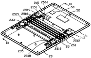
- FIG. 8 is a schematic diagram of the three-dimensional structure of the electronic device in the second embodiment of the present application after the back plate is removed.
- FIG. 9 is a cross-sectional view taken along the line IX-IX in FIG. 8.
- FIG. 10 is an enlarged view of a portion X in FIG. 9.
- FIG. 11 is a schematic diagram of a three-dimensional structure of a bent state of the electronic device in the second embodiment of the present application.
- FIG. 12 is a cross-sectional view taken along the line XII-XII in FIG. 11.
- FIG. 13 is a schematic diagram of the three-dimensional structure of the electronic device in the third embodiment of the present application after the back plate is removed.
- FIG. 14 is an enlarged view of a XIV portion in FIG. 13.
- FIG. 15 is a schematic diagram of a three-dimensional structure of a bent state of an electronic device in a third embodiment of the present application.
- FIG. 16 is an enlarged view of an XVI portion in FIG. 15.
- FIG. 1 is a schematic view of the three-dimensional structure of the electronic device in the first embodiment of the present application
- FIG. 2 is a schematic view of the electronic device in FIG. 1 from another perspective
- FIG. 4 is a schematic diagram of the three-dimensional structure of FIG. 3 from another perspective
- FIG. 5 is a cross-sectional view taken along the line VV in FIG.
- the electronic device 100 in the first embodiment of the present application includes a casing 20, a display screen 30 disposed on a front surface of the casing 20, and a motherboard 50 disposed in the casing 20.
- the housing 20 includes a first frame 21, a second frame 23, and a hinge device 25 connected between the first frame 21 and the second frame 23.
- the display screen 30 is disposed on the first frame body 21, the second frame body 23 and the hinge device 25.
- the display screen 30 is provided with a bendable area 31 corresponding to the hinge device 25 and two non-bendable areas 33 connected to opposite sides of the bendable area 31.
- the hinge device 25 includes a hinge body 251 and a detection member 256.
- the hinge body 251 is supported on the back of the bendable area 31 of the display screen 30.
- the detection member 256 is disposed between the hinge body 251 and the first frame body 21 or the hinge body 251. And the second frame body 23.
- the main board 50 is provided with a processor 52, and the detection member 256 and the display screen 30 are electrically connected to the processor 52.
- the detecting member 256 is configured to detect a sliding displacement amount of the first portion of the hinge main body 251 relative to the corresponding first frame 21 or the second portion of the second frame 23, and the processor 52 calculates the sliding displacement amount according to the sliding displacement amount.
- the opposite sides of the hinge body 251 are slidably connected to the first frame body 21 and the second frame body 23, respectively.
- the display screen 30 follows the hinge body 251 in the bendable area 31. Bending, under the pull of the display screen 30, the sides of the hinge body 251 and the corresponding first frame 21 and second frame 23 slide relative to each other in a direction perpendicular to the bending axis of the hinge body 251, and the detection member 256 The sliding displacement of the side of the hinge body 251 relative to the corresponding first frame 21 or second frame 23 is detected, and the distance value signal is transmitted to the processor 52.
- the processor 52 receives the distance value signal and calculates the display screen
- the bending angle value of 30, the processor 52 controls the display screen 30 to display a corresponding user interface according to the bending angle value.
- the sliding displacement between the side of the hinge body 251 and the corresponding first frame 21 or second frame 23 in the present application has a corresponding relationship with the rotation value of the hinge body 251.
- the rotation value refers to the hinge body 251.
- Bend angle value There is a unique correspondence between the amount of sliding displacement between the side of the hinge body 251 and the corresponding first frame body 21 or the second frame body 23 and the bending angle of the hinge body 251.
- the larger the bending angle value of the hinge body 251 is, the larger the sliding displacement amount between the side of the corresponding hinge body 251 and the corresponding first frame body 21 or the second frame body 23 is, for example, the hinge body 251
- the rotation value of the hinge body 251 is zero, that is, the bending angle value of the hinge body 251 is 0 degrees, and the side of the hinge body 251 is between the corresponding first frame body 21 or the second frame body 23
- the amount of sliding displacement is also zero; when the hinge body 251 is in a folded state, that is, the back of the first frame body 21 is attached to the back of the second frame body 23, at this time, the rotation value of the hinge body 251 is the largest, and the hinge body
- the bending angle value of 251 is the maximum value, and the sliding displacement amount between the side of the hinge body 251 and the corresponding first frame body 21 or the second frame body 23 is also the largest.
- the rotation value of the hinge body 251 gradually increases from zero to a maximum value.
- the side of the corresponding hinge body 251 and the corresponding first frame 21 or The amount of sliding displacement between the second frames 23 also gradually increased from zero to the maximum value.
- the rotation value of the hinge body 251 gradually decreased from the maximum value to zero.
- the amount of sliding displacement between the side of the corresponding hinge body 251 and the corresponding first frame body 21 or second frame body 23 also gradually decreases from the maximum value and eventually becomes zero. That is, the larger the bending angle value of the hinge body 251 is, the larger the sliding displacement amount is, and the smaller the bending angle value of the hinge body 251 is, the smaller the sliding displacement amount is.
- the bending axis of the hinge body 251 in the present application is not limited to a solid shaft, but may be a non-solid shaft, as long as the hinge body 251 can be bent around the axis, it can be regarded as a bending axis;
- the front of the housing 20 refers to the hinge body 251
- the side corresponding to the bent outer side after the bending, and the back side of the casing 20 refers to the side corresponding to the inner side after the hinge body 251 is bent.
- the display screen 30 can also be disposed on the back of the housing 20, and when the hinge body 251 is bent, the display screen 30 is located inside the bend.
- the electronic device 100 is, for example, but not limited to, any other product with a display function, such as a mobile phone, a tablet computer, a display, a liquid crystal panel, an OLED panel, a television, a smart watch, a VR head-mounted display, a car display, and the like. And parts.
- the hinge device 25 of the electronic device 100 of the present application includes a hinge body 251 slidably connected between the first frame body 21 and the second frame body 23, and the hinge body 251 and the first frame body 21 or the hinge body 251 and the first body
- the detection member 256 between the two frames 23.
- the sides of the hinge body 251 slide relative to the first frame 21 and the second frame 23, and the detecting member 256 detects the relative sliding displacement of the sides of the hinge body 251 and
- the distance value signal is transmitted to the processor 52.
- the processor 52 receives the distance value signal and calculates the bending angle value of the hinge body 251. Since the bending angle value of the hinge body 251 is the same as the bending angle value of the display screen 30, the detection is performed.
- the processor 52 controls the display screen 30 to display a corresponding user interface according to the bending angle value, so as to implement different bending angles of the display screen 30 of the electronic device 100 to display corresponding user interfaces. To improve the user experience.
- the first frame body 21 is provided with a first connection portion 212 on a side adjacent to the bendable area 31, and the first connection portion 212 is used to connect one side of the hinge body 251. .
- the first frame body 21 is provided with a guide slider 213 at opposite ends of a side adjacent to the first connecting portion 212, and each guide slider 213 is provided with a guide in a direction perpendicular to the bending axis of the hinge body 251. Chute 2131.
- Each guide sliding member 213 is provided with a positioning post 2135 in the guide sliding groove 2131. The positioning post 2135 extends along the normal direction of the back surface of the casing 20.
- a positioning block 215 is protruded from the first frame body 21 adjacent to each guide sliding member 213.
- a positioning hole 2151 is defined in the positioning block 215 along a direction perpendicular to the bending axis of the hinge body 251.
- the circuit board 50 is fixed in the first frame 21, and the detecting member 256 is disposed on the circuit board 50 adjacent to one of the guide sliding members 213.
- the structure of the second frame body 23 is similar to that of the first frame body 21, that is, the second frame body 23 is provided with a second connection portion 232 on a side adjacent to the bendable area 31, and the second connection portion 232 is used for Connected to the other side of the hinge body 251.
- the second frame body 23 is provided with a guide slider 233 at opposite ends of a side adjacent to the second connecting portion 232, and each guide slider 233 is provided with a guide in a direction perpendicular to the bending axis of the hinge body 251.
- Each guide sliding member 233 is provided with a positioning post 2335 in the guide sliding groove 2331.
- the positioning post 2335 extends along the normal direction of the back surface of the housing 20.
- a positioning block 235 is protruded from the second frame body 23 adjacent to each guide sliding member 233.
- a positioning hole 2351 is defined in the positioning block 235 along a direction perpendicular to the bending axis of the hinge body 251.
- the hinge main body 251 is composed of a plurality of link chains and a plurality of gear transmission mechanisms.
- One side of the hinge main body 251 is provided with a first mounting portion 2510 corresponding to the first connection portion 212 of the first frame body 21.
- the first mounting portion 2510 is used to connect the first connection portion 212 of the first frame body 21.
- a pair of sliding rails 2512 are respectively protruding from opposite ends of the hinge main body 251 on one side of the first mounting portion 2510 in a direction perpendicular to the bending axis of the hinge main body 251, and the two sliding rails 2512 respectively correspond to the first frame body 21.
- a positioning slot 2516 is defined in the middle of each slide rail 2512 along its length direction.
- each slide rail 2512 corresponds to a positioning post 2135 in the guide slide slot 2131 of the corresponding guide slide 213.
- a guide hole 2513 is defined in the first mounting portion 2510 adjacent to each slide rail 2512.
- the guide slide hole 2513 extends in a direction parallel to the slide rail 2512.
- a second mounting portion 2514 is provided on the other side of the hinge body 251 corresponding to the second connection portion 232 of the second frame body 23. The second mounting portion 2514 is used to connect the second connection portion 232.
- a pair of sliding rails 2515 are protruded from the opposite ends of the hinge main body 251 adjacent to the second mounting portion 2514 in a direction perpendicular to the bending axis of the hinge main body 251, and the two sliding rails 2515 respectively correspond to the second frame.
- the two guide slides 23 of the two guide slides 233 are 2331.
- a positioning groove 2511 is defined in a middle portion of each slide rail 2515 along a length direction thereof.
- the positioning groove 2511 of each slide rail 2515 corresponds to a positioning post 2335 in the guide slide groove 2331 of the corresponding guide slide 233.
- a guide hole 2517 is defined on the second mounting portion 2514 adjacent to each slide rail 2515.
- the guide slide hole 2517 extends in a direction parallel to the slide rail 2515.
- the hinge body 251 further includes four guide posts 2518 and four elastic members 2519.
- each of the elastic members 2519 is an elastic spring, and a stopper is provided at an end of each guide post 2518 away from the hinge body
- the detecting member 256 is a distance sensor, and the distance sensor is electrically connected to the processor 52 on the circuit board 50.
- the distance sensor is disposed on the circuit board 50.
- the distance sensor is directly opposite to the guide groove 2131 of one of the guide sliders 213, and there is a gap between the distance sensor and the one of the guide sliders 213.
- the distance sensor detects the distance between the slide rail 2512 and the first by sensing the distance between the guide rail 2512 and the corresponding end of the slide rail 2512.
- the processor 52 controls the display screen 30 to display a corresponding user interface according to the bending angle value.
- the width of the gap between the distance sensor and the sliding guide 213 is greater than or equal to the maximum sliding displacement of the slide rail 2512.
- the first connection portion 212 of the first frame body 21 is connected to the first mounting portion 2510 of the hinge body 251, and the two slide rails 2512 are slid separately. Inserted into the guide grooves 2131 of the two guide slides 213, the two positioning posts 2135 are slidably inserted into the positioning grooves 2516 of the two slide rails 2512, and the two guide slide holes 2513 are positioned opposite the two Positioning hole 2151 of the block 215.
- the two positioning posts 2135 can prevent each of the slide rails 2512 on the first mounting portion 2510 from detaching from the corresponding guide member 213 during the sliding process of the hinge body 251.
- the second connecting portion 232 of the second frame body 23 is connected to the second mounting portion 2514 of the hinge body 251, and the two slide rails 2515 are slidably inserted into the guide grooves 2331 of the two guide members 233, respectively.
- the two positioning posts 2335 are slidably inserted into the positioning grooves 2511 of the two slide rails 2515, and the two guide sliding holes 2517 are respectively opposite to the positioning holes 2351 of the two positioning blocks 235.
- the two positioning posts 2335 can prevent each of the slide rails 2515 on the second mounting portion 2514 from being detached from the corresponding guide member 233 during the sliding process of the hinge body 251.
- the hinge body 251 is connected between the first frame body 21 and the second frame body 23; each elastic member 2519 abuts between the hinge body 251 and the corresponding positioning block 215, 235, and each guide post 2518 is positioned on the corresponding positioning block 215, 235 and the stop block stops on the side of the positioning block 215, 235 facing away from the elastic member 2519; the distance sensor faces one of the slide rails 2512 facing away from the end face of the hinge body 251 There is a gap between the distance sensor and an end surface of one of the slide rails 2512, and a length value of the gap changes as the slide rail 2512 slides.
- each slide rail 2512, 2515 slides in the guide groove 2131 of the corresponding guide slide 213, and the distance sensor can detect the sliding displacement of the corresponding slide rail 2512.
- the distance value signal is transmitted to the processor 52.
- the distance from the distance sensor to the end surface of the corresponding slide rail 2512 is greater than or equal to the maximum sliding displacement of the slide rail 2512.
- FIG. 6 is a schematic diagram of a three-dimensional structure of a bent state of the electronic device in the first embodiment of the present application.
- FIG. 7 is a sectional view taken along the line VII-VII in FIG. 6.
- the electronic device 100 is bent through the hinge body 251, and the display screen 30 is bent along the bendable area 31 with the hinge body 251, that is, the bending angle value of the display screen 30 is equal to the bending angle value of the hinge body 251.
- the two slide rails 2512 on the first mounting portion 2510 of the hinge body 251 slide along the guide grooves 2131 of the corresponding guide slide 213 toward the first frame 21, that is, slide toward the distance sensor.
- the two slide rails 2515 on the second mounting portion 2514 of the main body 251 slide along the slide grooves 2331 of the corresponding guide members 233 toward the second frame body 23.
- the distance sensor detects a sliding displacement of the corresponding slide rail 2512, and transmits a distance value signal to the processor 52.
- the processor 52 receives the distance value signal and calculates a bending angle value of the hinge body 251. That is, the bending angle value of the display screen 30 is obtained.
- the processor 52 controls the display screen 30 to display a corresponding user interface according to the bending angle value, thereby improving the user experience.
- the hinge body 251 During the change of the hinge body 251 from flattened to bent, the distance between the distance sensor and the end surface of the slide rail 2512 is changed from large to small; the hinged main body 251 is bent from flattened to flattened. During the change, the distance between the distance sensor and the end surface of the slide rail 2512 changed from small to large.
- a damping device is provided in the hinge body 251 to bend the hinge body 251 to any angle and position it, that is, the display screen 30 can be bent to any angle along the bendable area 31 and positioned at any angle.
- the distance sensor can detect the sliding displacement of the corresponding slide rail 2512 and transmit a distance value signal to the processor 52.
- the processor 52 receives the distance value signal and calculates the bending angle value of the hinge body 251.
- the display screen 30 is controlled to display a corresponding user interface according to the bending angle value.
- FIG. 8 is a schematic diagram of the three-dimensional structure of the electronic device in the second embodiment of the present application.
- FIG. 9 is a cross-sectional view taken along line IX-IX in FIG. 8.
- the structure of the second embodiment of the electronic device of the present application is similar to that of the first embodiment, except that the detection element in the second embodiment is different from the detection element in the first embodiment, and in the second embodiment
- the detecting element is a pressure sensor 256a.
- the pressure sensor 256a is used to detect a pressure value during bending of the hinge body 251.
- the pressure sensor 256a is electrically connected to the processor 52.
- the pressure sensor 256a A pressure value signal is transmitted to the processor 52, and the processor 52 receives the pressure value signal and calculates a bending angle value of the display screen 30. Specifically, the pressure sensor 256a is in contact with one end of one of the elastic members 2519, that is, an end of one of the elastic members 2519 is in contact with the detecting member 256a.
- the pressure sensor 256a is used to detect the pressure value of the hinge body 251 against the elastic member 2519 during the bending process, and the pressure sensor 256a transmits the detected pressure value signal to the processor 52, and the processor 52 Receive the pressure value signal and calculate the bending angle value of the hinge body 251, that is, the bending angle value of the display screen 30, and the processor 52 controls the display screen 30 to display according to the bending angle value The corresponding user interface.
- FIG. 10 is an enlarged view of a portion X in FIG. 9.
- the pressure sensor 256a is disposed at an end of one of the elastic members 2519. Specifically, the pressure sensor 256a is disposed between one of the positioning blocks 215 on the first frame 21 and the corresponding elastic member 2519, that is, The end of the elastic member 2519 adjacent to the positioning block 215 abuts the pressure sensor 256a.
- the elastic member 2519 is a spring sleeved on the guide post 2518, and the pressure sensor 256a abuts between the end of the spring and the corresponding positioning block 215.
- the elastic member 2519 is compressed as the hinge body 251 is bent.
- the elastic member 2519 presses against the pressure sensor 256a.
- the pressure sensor 256a detects a pressure value and transmits a pressure value signal to the processor 52.
- the pressure value detected by the pressure sensor 256a changes from small to large; during the change of the hinge body 251 from bend to flat, the pressure sensor 256a The detected pressure value changes from large to small. That is, the pressure value detected by the pressure sensor 256a increases with the sliding displacement of the first frame 21 or the second frame 23 corresponding to the hinge body 251, and increases with the hinge body 251. The amount of sliding displacement of the corresponding first frame body 21 or second frame body 23 is reduced to decrease.
- FIG. 11 is a schematic diagram of a three-dimensional structure of a bent state of the electronic device in the second embodiment of the present application.
- FIG. 12 is a cross-sectional view taken along line XII-XII in FIG. 11.
- the electronic device 100 is bent through the hinge body 251, and the display screen 30 is bent along the bendable area 31 with the hinge body 251, that is, the bending angle value of the display screen 30 is equal to the bending angle value of the hinge body 251.
- the two slide rails 2512 on the first mounting portion 2510 of the hinge body 251 slide along the corresponding guide grooves 2131 of the corresponding slide members 213 toward one side of the first frame body 21.
- the outer end surface of the guide sliding hole 2513 on the first mounting portion 2510 slides along the corresponding guide post 2518 to press against the corresponding elastic member 2519.
- the outer end surface of the guide sliding hole 2517 on the second mounting portion 2514 corresponds to The guide post 2518 slides to press the corresponding elastic member 2519.
- the pressure sensor 256a is pressed by the corresponding elastic member 2519.
- the pressure sensor 256a detects the pressure value of the elastic member 2519 and transmits a pressure value signal to the processor 52. After the processor 52 receives the pressure value signal, After calculation, the bending angle value of the hinge body 251, that is, the bending angle value of the display screen 30, the processor 52 controls the display screen 30 to display a corresponding user interface according to the bending angle value, thereby improving user experience.
- a damping device is provided in the hinge body 251 to bend the hinge body 251 to any angle and position it, that is, the display screen 30 can be bent to any angle along the bendable area 31 and positioned at any angle.
- the pressure sensor 256a can detect the pressure value of the elastic member 2519 and transmit a pressure value signal to the processor 52.
- the processor 52 receives the pressure value signal and calculates the bending angle value of the hinge body 251.
- the controller 52 controls the display screen 30 to display a corresponding user interface according to the bending angle value.
- the pressure sensor 256a may be disposed between one of the positioning blocks 235 on the second frame body 23 and the corresponding elastic member 2519, and the pressure sensor 256a is electrically connected to the processor 52.
- the pressure sensor 256a may be disposed at one end of one of the elastic members 2519 adjacent to the hinge body 251.
- the pressure sensor 256a may also be disposed between the first mounting portion 2510 and an end of one of the elastic members 2519, or between the second mounting portion 2514 and an end of one of the elastic members 2519. between.
- FIG. 13 is a schematic diagram of the three-dimensional structure of the electronic device in the third embodiment of the present application
- FIG. 14 is an enlarged view of the XIV part in FIG. 13
- FIG. 16 is an enlarged view of the XVI part in FIG. 15.
- the structure of the third embodiment of the electronic device of the present application is similar to that of the first embodiment, except that the detection element in the third embodiment is different from the detection element in the first embodiment, and in the third embodiment
- the detecting element 256b is a sliding varistor.
- the sliding varistor 256b is used to detect the sliding displacement of the hinge body 251 relative to the first frame 21 or the second frame 23 during bending.
- the sliding varistor 256b is electrically Connected to the processor 52, the resistance value of the sliding rheostat 256b changes with the sliding displacement of the hinge body 251, that is, changes with the sliding of the hinge body 251 relative to the sliding of the housing 20,
- the sliding rheostat 256b transmits a resistance value signal to the processor 52, and the processor 52 receives the resistance value signal and calculates a bending angle value of the hinge body 251, that is, the bending of the display screen 30
- the processor 52 controls the display screen 30 to display a corresponding user interface according to the bending angle value.
- the slide varistor 256 b is disposed on the main board 50 and corresponds to one of the slide rails 2512.
- the slide varistor 256 b includes a fixed end 2562 electrically connected to the processor 52 through the main board 50, and is connected to the slide rail 2512.
- a sliding end of 2564 is connected to the end of the slide rail 2512, and the other end is slidably connected to the fixed end 2562.
- the slide rail 2512 slides along the guide groove 2131 of the corresponding guide slide 213 as the hinge body 251 is bent.
- the slide rail 2512 drives the slide end 2564 to slide to change the resistance value of the slide rheostat 256, that is, The resistance value of the sliding varistor changes as the sliding rail 2512 slides.
- the sliding rail 2512 slides the sliding end 2564 toward the side of the first frame 21, so that the resistance of the sliding rheostat 256b changes from large to small;
- the slide rail 2512 slidingly drives the sliding end 2564 to slide away from the first frame 21, and the pressure value detected by the pressure sensor changes from small to large.
- the resistance value of the sliding varistor 256b changes from small to large during the change from flattening to bending of the hinge body 251;
- the resistance of the sliding rheostat 256b changes from large to small.
- the electronic device 100 is bent through a hinge body 251, and the display screen 30 is bent along the bendable area 31 along with the hinge body 251.
- the two slide rails 2512 on the first mounting portion 2510 of the hinge body 251 correspond to each other.
- the guide groove 2131 of the guide slider 213 slides toward a side away from the hinge body 251.
- One of the slide rails 2512 drives the sliding end 2564 to slide.
- the resistance value of the sliding varistor 256 decreases as the sliding end 2564 slides.
- the sliding varistor 256b inputs a resistance value to the processor 52, and the processor 52 receives all
- the resistance value and the bending angle value of the hinge body 251 is calculated according to the input resistance value, that is, the bending angle value of the display screen 30 is obtained, and the processor 52 then calculates the bending angle value according to the bending angle value
- the control display screen 30 displays a corresponding user interface, thereby improving the user experience.
- a damping device is provided in the hinge body 251 to bend the hinge body 251 to any angle and perform positioning.
- the sliding rheostat 256b can obtain a corresponding resistance value and transmit the resistance value to the processor 52.
- the processor 52 receives the resistance value and calculates a bending angle value of the hinge body 251, and the processor 52 controls the display screen 30 to display a corresponding user interface according to the bending angle value.
- the sliding varistor may be disposed on the second frame 23 adjacent to one of the sliding rails 2515, that is, the sliding varistor is electrically connected to the processor 25, and the sliding end of the sliding varistor 2564 Connected to one of the slide rails 2515.
- the term “relative sliding” in the present invention does not limit direct contact and relative sliding between two components, but may also include relative sliding between third-party components, and third-party components are not limited to solid components, such as tablets. Materials, film materials, etc., but can also include non-solid elements, such as gaps, spaces, etc., or a combination of solid elements and non-solid elements; third-party elements are not limited to one, but can include multiple. That is, as long as the two elements have a relative sliding motion relationship, regardless of the actual position of the two elements, it can be considered to be within the range of “relative sliding” as referred to in the present invention.
Landscapes
- Engineering & Computer Science (AREA)
- Theoretical Computer Science (AREA)
- General Engineering & Computer Science (AREA)
- Human Computer Interaction (AREA)
- Physics & Mathematics (AREA)
- General Physics & Mathematics (AREA)
- Telephone Set Structure (AREA)
- Devices For Indicating Variable Information By Combining Individual Elements (AREA)
Abstract
提供一种电子装置、电子装置的壳体及铰链装置,电子装置(100)包括柔性显示屏(30)、壳体(20),以及主板(50),主板(50)上设置有处理器(52),壳体(20)包括第一框体(21)、第二框体(23)及铰链装置(25),铰链装置(25)连接于第一框体(21)与第二框体(23)之间,铰链装置(25)包括铰链主体(251)及检测件(256),显示屏(30)对应铰链主体(251)设置有可折弯区(31),检测件(256)电性连接于处理器(52),检测件(256)用于检测铰链主体(251)的第一部分相对对应的第一框体(21)的第二部分的滑动位移量,处理器(52)根据滑动位移量计算出显示屏(30)沿可折弯区(31)的折弯角度值。能够根据电子装置的显示屏不同的折弯角度显示相应的用户界面,提高了用户体验。
Description
本申请涉及显示屏支撑领域,尤其涉及一种支撑显示屏的铰链装置、设置有所述铰链装置的壳体,以及设置有所述壳体的电子装置。
随着显示屏的发展,现有技术中已经出现了折叠式显示屏的电子装置,现有的折叠式显示屏一般通过铰链来实现显示屏的折弯。所述折叠式显示屏有时需依据不同的弯折角度值来调用相应的用户界面,以满足不同的交互需求。因此,有必要提供一种能够测量显示屏弯折角度的装置。
发明内容
本申请提供一种能检测弯折角度的铰链装置、设置有所述铰链装置的壳体,以及设置有所述壳体的电子装置。
本申请提供的一种铰链装置,用于支撑设置于壳体的第一框体与第二框体上的显示屏,所述铰链装置位于所述第一框体与所述第二框体之间,所述铰链装置包括铰链主体及检测件,所述显示屏对应所述铰链主体设置有可折弯区,所述检测件电性连接于处理器,所述检测件用于检测所述铰链主体的第一部分相对对应的第一框体的第二部分的滑动位移量,所述处理器根据所述滑动位移量计算出所述显示屏沿所述可折弯区的折弯角度值。
本申请还提供一种壳体,包括第一框体、第二框体及铰链装置,所述铰链装置连接于所述第一框体与所述第二框体之间,所述铰链装置包括铰链主体及检测件,所述显示屏对应所述铰链主体设置有可折弯区,所述检测件电性连接于处理器,所述检测件用于检测所述铰链主体的第一部分相对对应的第一框体的第二部分的滑动位移量,所述处理器根据所述滑动位移量计算出所述显示屏沿所述可折弯区的折弯角度值。
本申请还提供一种电子装置,包括柔性屏、壳体,以及主板,所述主板上设置有处理器,所述壳体包括第一框体、第二框体及铰链装置,所述铰链装置连接于所述第一框体与所述第二框体之间,所述铰链装置包括铰链主体及检测件,所述显示屏对应所述铰链主体设置有可折弯区,所述检测件电性连接于的处理器,所述检测件用于检测所述铰链主体的 第一部分相对对应的第一框体的第二部分的滑动位移量,所述处理器根据所述滑动位移量计算出所述显示屏沿所述可折弯区的折弯角度值。
本申请电子装置的铰链装置包括滑动地连接于第一框体与第二框体之间的铰链主体,以及设置于铰链主体的第一部分与第一框体的第二部分之间的检测件。当电子装置折弯时,所述铰链主体相对于第一框体滑动,所述检测件能检测出铰链主体的第一部分的相对于对应的第一框体的第二部分的滑动位移量并传输信号给处理器,处理器接收信号并计算出显示屏的折弯角度值,所述处理器再根据所述折弯角度值控制显示屏显示相应的用户界面,从而实现电子装置的显示屏不同的折弯角度显示相应的用户界面,提高了用户体验。
为了更清楚地说明本发明实施例中的技术方案,下面将对实施例中所需要使用的附图作简单地介绍,显而易见地,下面描述中的附图仅仅是本发明的一些实施例,对于本领域普通技术人员来讲,在不付出创造性劳动的前提下,还可以根据这些附图获得其他的附图。
图1是本申请第一实施例中的电子装置的立体结构示意图。
图2是图1中的电子装置去除背板后的另一视角的结构示意图。
图3是图2中的立体结构分解示意图。
图4是图3的另一视角的立体结构示意图。
图5是图2中沿V-V线的剖视图。
图6是本申请第一实施例中的电子装置的折弯状态的立体结构示意图。
图7是图6中沿VII-VII线的剖视图。
图8是本申请第二实施例中的电子装置去除背板后的立体结构示意图。
图9是图8中沿IX-IX线的剖视图。
图10是图9中X部分的放大图。
图11是本申请第二实施例中的电子装置的折弯状态的立体结构示意图。
图12是图11中沿XII-XII线的剖视图。
图13是本申请第三实施例中的电子装置去除背板后的立体结构示意图。
图14是图13中XIV部分的放大图。
图15是本申请第三实施例中的电子装置的折弯状态的立体结构示意图。
图16是图15中XVI部分的放大图。
下面将结合本发明实施例中的附图,对本发明实施例中的技术方案进行清楚、完整地描述,显然,所描述的实施例仅是本发明一部分实施例,而不是全部的实施例。基于本发明中的实施例,本领域普通技术人员在没有做出创造性劳动前提下所获得的所有其他实施例,都属于本发明保护的范围。
本发明实施例的描述中,需要理解的是,术语“上”、“下”“左”“右”等指示的方位或位置关系为基于附图所示的方位或位置关系,仅是为了便于描述本发明和简化描述,而不是暗示或指示所指的装置或元件必须具有特定的方位、以特定的方位构造和操作,因此不能理解为对本发明的限制。
请一并参阅图1至图5,图1是本申请第一实施例中的电子装置的立体结构示意图;图2是图1中的电子装置的另一视角的结构示意图;图3是图2中的电子装置的立体结构分解示意图;图4是图3的另一视角的立体结构示意图;图5是图2中沿V-V线的剖视图。本申请的第一实施例中的电子装置100包括一壳体20、设置于所述壳体20的正面上的一显示屏30,以及设置于所述壳体20内的一主板50。所述壳体20包括一第一框体21、一第二框体23及连接于第一框体21与第二框体23之间的一铰链装置25。显示屏30设置于所述第一框体21、第二框体23及铰链装置25上。显示屏30设置有对应铰链装置25的一可折弯区域31,以及连接于可折弯区域31相对的两侧的两个非折弯区域33。铰链装置25包括一铰链主体251及一检测件256,铰链主体251支撑于显示屏30的可折弯区域31的背面,检测件256设置于铰链主体251与第一框体21之间或铰链主体251与第二框体23之间。主板50上设置有处理器52,检测件256及显示屏30均电性连接于处理器52。所述检测件256用于检测所述铰链主体251的第一部分相对对应的第一框体21或第二框体23的第二部分的滑动位移量,处理器52根据所述滑动位移量计算出显示屏30沿可折弯区31的折弯角度值。
具体的,铰链主体251相对的两侧边分别滑动地连接于第一框体21及第二框体23,当铰链主体251折弯时,显示屏30随着铰链主体251于可折弯区31折弯,在显示屏30的拉动下,铰链主体251的侧边与对应的第一框体21及第二框体23之间沿垂直于铰链主体251的弯曲轴的方向相对滑动,检测件256检测出铰链主体251的侧边相对对应的第一框体21或第二框体23的滑动位移量,并将距离值信号传输给处理器52,处理器52接收距离值信号并计算出显示屏30的折弯角度值,处理器52根据所述折弯角度值控制显示屏30显示相应的用户界面。
本申请中的铰链主体251的侧边与对应的第一框体21或第二框体23之间的滑动位移量与铰链主体251的转动值存在对应关系,所述转动值是指铰链主体251的折弯角度值。铰链主体251的侧边与对应的第一框体21或第二框体23之间的滑动位移量与铰链主体251的折弯角度存在唯一对应关系。具体的,铰链主体251的折弯角度值越大对应的铰链主体251的侧边与对应的第一框体21或第二框体23之间的滑动位移量就越大,如,铰链主体251为平展状态时,铰链主体251的转动值为零,即,铰链主体251的折弯角度值为0度,铰链主体251的侧边与对应的第一框体21或第二框体23之间的滑动位移量也为零;当铰链主体251呈对折状态时,即,第一框体21的背面贴接于第二框体23的背面,此时,铰链主体251的转动值最大,铰链主体251的折弯角度值为最大值,铰链主体251的侧边与对应的第一框体21或第二框体23之间的滑动位移量也最大。由此可知,铰链主体251由平展状态至折弯状态的过程中,铰链主体251的转动值由零逐渐增大至最大值,对应的铰链主体251的侧边与对应的第一框体21或第二框体23之间的滑动位移量也由零逐渐增大至最大值;铰链主体251由折弯状态至平展状态的过程中,铰链主体251的转动值由最大值逐渐减少最终为零,对应的铰链主体251的侧边与对应的第一框体21或第二框体23之间的滑动位移量也由最大值逐渐减少最终为零。即,铰链主体251的折弯角度值越大所述滑动位移量越大,铰链主体251的折弯角度值越小所述滑动位移量越小。
本申请中铰链主体251的弯曲轴并非限定是实体的轴,也可以是非实体的轴,只要铰链主体251能够绕该轴弯曲均可以认为是弯曲轴;所述壳体20的正面指铰链主体251弯折后的弯折外侧对应的一面,所述壳体20的背面指铰链主体251弯折后弯折内侧对应的一面。可以理解的是,显示屏30也可以设置在壳体20的背面,铰链主体251弯折时,显示屏30位于弯折内侧。
本实施例中,所述电子装置100例如是,但不局限于手机、平板电脑、显示器、液晶面板、OLED面板、电视、智慧手表、VR头戴显示器、车载显示器等其它任何具有显示功能的产品和部件。
本申请电子装置100的铰链装置25包括滑动地连接于第一框体21与第二框体23之间的铰链主体251,以及设置于铰链主体251与第一框体21或铰链主体251与第二框体23之间的检测件256。当电子装置100通过铰链主体251折弯时,铰链主体251的侧边相对于第一框体21及第二框体23滑动,检测件256检测出铰链主体251的侧边的相对滑动位移量并传输距离值信号给处理器52,处理器52接收距离值信号并计算出铰链主体251的折弯角度值,由于铰链主体251的折弯角度值与显示屏30的折弯角度值相同,从而检测出 显示屏30的折弯角度值,处理器52再根据所述折弯角度值控制显示屏30显示相应的用户界面,从而实现电子装置100的显示屏30不同的折弯角度显示相应的用户界面,提高了用户体验。
如图3及图4所示,第一框体21于邻近可折弯区域31的一侧设置有一第一连接部212,所述第一连接部212用于连接所述铰链主体251的一侧。第一框体21于邻近所述第一连接部212的一侧的相对的两端分别设有一导滑件213,每一导滑件213沿垂直于铰链主体251的弯曲轴的方向开设有导滑槽2131。每一导滑件213于所述导滑槽2131内设置有一定位柱2135,所述定位柱2135沿壳体20的背面的法线方向延伸。第一框体21于邻近每一导滑件213处凸设有一定位块215,定位块215上沿垂直于铰链主体251的弯曲轴的方向开设有定位孔2151。电路板50固定于第一框体21内,所述检测件256邻近其中一导滑件213设置于电路板50上。
第二框体23的结构与第一框体21的结构相似,即,第二框体23于邻近可折弯区域31的一侧设置有一第二连接部232,所述第二连接部232用于连接所述铰链主体251的另一侧。第二框体23于邻近所述第二连接部232的一侧的相对的两端分别设有一导滑件233,每一导滑件233沿垂直于铰链主体251的弯曲轴的方向开设有导滑槽2331。每一导滑件233于所述导滑槽2331内设置有一定位柱2335,所述定位柱2335沿壳体20的背面的法线方向延伸。第二框体23于邻近每一导滑件233处凸设有一定位块235,定位块235上沿垂直于铰链主体251的弯曲轴的方向开设有定位孔2351。
所述铰链主体251由若干节链条与若干齿轮传动机构组成,所述铰链主体251的一侧对应第一框体21的第一连接部212设置有一第一安装部2510,所述第一安装部2510用于连接所述第一框体21的第一连接部212。铰链主体251于所述第一安装部2510的一侧的相对的两端沿垂直于铰链主体251的弯曲轴的方向分别凸设有一滑轨2512,两个滑轨2512分别对应第一框体21的两个导滑件213的导滑槽2131。每一滑轨2512的中部沿其长度方向开设有定位槽2516,每一滑轨2512的定位槽2516对应相应的导滑件213的导滑槽2131内的定位柱2135。第一安装部2510于邻近每一滑轨2512处开设有一导滑孔2513,导滑孔2513沿平行于滑轨2512的方向延伸。所述铰链主体251的另一侧对应第二框体23的第二连接部232设置有一第二安装部2514,所述第二安装部2514用于连接第二连接部232。铰链主体251于邻近所述第二安装部2514的一侧的相对的两端沿垂直于铰链主体251的弯曲轴的方向分别凸设有一滑轨2515,两个滑轨2515分别对应第二框体23的两个导滑件233的导滑槽2331。每一滑轨2515的中部沿其长度方向开设有定位槽2511,每一滑轨2515的 定位槽2511对应相应的导滑件233的导滑槽2331内的定位柱2335。第二安装部2514上邻近每一滑轨2515处开设有一导滑孔2517,导滑孔2517沿平行于滑轨2515的方向延伸。铰链主体251还包括四个导柱2518及四个弹性件2519。本实施例中,每一弹性件2519为弹性弹簧,每一导柱2518远离铰链主体251的一端设置有一止挡块。
本实施例中,检测件256为距离传感器,所述距离传感器电性连接于电路板50上的处理器52。所述距离传感器设置于电路板50上,所述距离传感器正对其中一导滑件213的导滑槽2131,所述距离传感器与所述其中一导滑件213之间有间隙。当滑轨2512滑动地插入所述其中一导滑件213的导滑槽2131内时,所述距离传感器通过感测其与滑轨2512相应末端之间的距离,来检测滑轨2512与第一框体21之间的滑动位移量,并将距离值信号传输给所述处理器52,处理器52经计算得出铰链主体251的折弯角度值,从而得出显示屏30的折弯角度值,所述处理器52根据所述折弯角度值控制显示屏30显示相应的用户界面。所述距离传感器与导滑件213之间的间隙的宽度大于或等于滑轨2512的最大滑动位移量。
请一并参阅图2至图6,组装时,将所述第一框体21的第一连接部212连接于所述铰链主体251的第一安装部2510,使两个滑轨2512分别滑动地插入两个导滑件213的导滑槽2131内,两个定位柱2135分别可滑动地插接于两个滑轨2512的定位槽2516内,且两个导滑孔2513分别正对两个定位块215的定位孔2151。两个定位柱2135能防止铰链主体251在滑动的过程中,第一安装部2510上的每一滑轨2512从对应的导滑件213内脱离。将所述第二框体23的第二连接部232连接于所述铰链主体251的第二安装部2514,使两个滑轨2515分别滑动地插入两个导滑件233的导滑槽2331内,两个定位柱2335分别可滑动地插接于两个滑轨2515的定位槽2511内,且两个导滑孔2517分别正对两个定位块235的定位孔2351。两个定位柱2335能防止铰链主体251在滑动的过程中,第二安装部2514上的每一滑轨2515从对应的导滑件233内脱离。将四个导柱2518分别从定位块215、235的定位孔2151、2351远离所述铰链主体251的一端插入,再穿过四个弹性件2519后可滑动地插入对应的导滑孔2513、2517内,每一导柱2518的止挡块分别抵顶于定位孔2151、2351外。将显示屏30的可折弯区域31贴接于铰链主体251的正面,将两个非折弯区域33分别贴接于第一框体21及第二框体23的正面。此时,所述铰链主体251连接于第一框体21与第二框体23之间;每一弹性件2519抵接于铰链主体251与对应的定位块215、235之间,每一导柱2518定位于对应的定位块215、235上且止挡块挡止于定位块215、235背朝弹性件2519的一侧;所述距离传感器正对其中一滑轨2512背朝铰链主体251的端面, 所述距离传感器与所述其中一滑轨2512的端面之间有间隙,所述间隙的长度值随所述滑轨2512的滑动而改变。当电子装置100沿铰链主体251折弯时,每一滑轨2512、2515在对应的导滑件213的导滑槽2131内滑动,所述距离传感器能检测出对应的滑轨2512的滑动位移量并传输距离值信号给处理器52。当所述显示屏30平展时,所述距离传感器至对应的滑轨2512的端面的距离大于或等于所述滑轨2512的最大的滑动位移量。
请一并参阅图6及图7,图6是本申请第一实施例中的电子装置的折弯状态的立体结构示意图。图7是图6中沿VII-VII线的剖视图。使用时,电子装置100通过铰链主体251折弯,显示屏30随铰链主体251沿可折弯区域31进行折弯,即,显示屏30的折弯角度值等于铰链主体251的折弯角度值,所述铰链主体251的第一安装部2510上的两个滑轨2512沿对应的导滑件213的导滑槽2131朝向第一框体21滑动,即,朝向所述距离传感器滑动,所述铰链主体251的第二安装部2514上的两个滑轨2515沿对应的导滑件233的滑槽2331朝向第二框体23滑动。所述距离传感器检测对应的滑轨2512的滑动位移量,并将距离值信号传输给处理器52,处理器52接收所述距离值信号经计算得出所述铰链主体251的折弯角度值,即,得出显示屏30的折弯角度值。所述处理器52根据折弯角度值控制显示屏30显示相应的用户界面,从而提高用户体验。
在所述铰链主体251由平展至折弯的变化过程中,所述距离传感器与所述滑轨2512的端面之间的距离值由大变小;在所述铰链主体251由折弯至平展的变化过程中,所述距离传感器与所述滑轨2512的端面之间的距离值由小变大。
本实施例中,铰链主体251内设置有阻尼装置能将铰链主体251折弯至任一角度并进行定位,即,显示屏30能沿可折弯区域31折弯至任一角度并定位在所述角度位置,所述距离传感器能检测出对应的滑轨2512的滑动位移量,并传输距离值信号给处理器52,处理器52接收距离值信号并计算出铰链主体251的折弯角度值,且根据所述折弯角度值控制显示屏30显示相应的用户界面。
请参阅图8及图9,图8是本申请第二实施例中的电子装置的立体结构示意图;图9是图8中沿IX-IX线的剖视图。本申请的电子装置的第二实施例的结构与第一实施例的结构相似,不同之处在于:第二实施例中的检测件与第一实施例中的检测件不同,在第二实施例中,检测件是压力传感器256a,所述压力传感器256a用于检测所述铰链主体251折弯过程中的压力值,所述压力传感器256a电性连接于所述处理器52,所述压力传感器256a将压力值信号传输给所述处理器52,所述处理器52接收所述压力值信号经计算得出所述显示屏30的折弯角度值。具体的,所述压力传感器256a抵接于其中一弹性件2519的一端, 即,其中一弹性件2519的端部抵接于检测件256a。所述压力传感器256a用于检测铰链主体251在折弯过程中抵推弹性件2519的压力值,所述压力传感器256a将检测到的压力值信号传输给所述处理器52,所述处理器52接收所述压力值信号并计算得出所述铰链主体251的折弯角度值,即,显示屏30的折弯角度值,所述处理器52再根据所述折弯角度值控制显示屏30显示相应的用户界面。
如图10所示,图10是图9中X部分的放大图。所述压力传感器256a设置于其中一弹性件2519的端部,具体的,所述压力传感器256a设置于所述第一框体21上的其中一定位块215与对应的弹性件2519之间,即,所述弹性件2519邻近定位块215的端部抵接于所述压力传感器256a。本实施例中,弹性件2519是套设于导柱2518上的弹簧,所述压力传感器256a抵接于所述弹簧的端部与对应的定位块215之间。
弹性件2519随所述铰链主体251的折弯而被压缩,所述弹性件2519抵压所述压力传感器256a,所述压力传感器256a检测出压力值并传输压力值信号给所述处理器52。在铰链主体251由平展至折弯的变化过程中,所述压力传感器256a检测到的压力值由小变大;在所述铰链主体251由折弯至平展的变化过程中,所述压力传感器256a检测到的压力值由大变小。也就是所述压力传感器256a检测出的压力值随所述铰链主体251相对对应的第一框体21或第二框体23的滑动位移量的增大而增大,随所述铰链主体251相对对应的第一框体21或第二框体23的滑动位移量的减小而减小。
请参阅图11及图12,图11是本申请第二实施例中的电子装置的折弯状态的立体结构示意图;图12是图11中沿XII-XII线的剖视图。使用时,电子装置100通过铰链主体251折弯,显示屏30随铰链主体251沿可折弯区域31进行折弯,即,显示屏30的折弯角度值等于铰链主体251的折弯角度值。所述铰链主体251的第一安装部2510上的两个滑轨2512沿对应的导滑件213的导滑槽2131朝向第一框体21的一侧滑动。所述第一安装部2510上的导滑孔2513的外端面沿对应的导柱2518滑动而抵压对应的弹性件2519,所述第二安装部2514上的导滑孔2517的外端面沿对应的导柱2518滑动而抵压对应的弹性件2519。所述压力传感器256a被对应的弹性件2519抵压,所述压力传感器256a检测出所述弹性件2519的压力值并将压力值信号传输给处理器52,处理器52接收所述压力值信号后经计算得出所述铰链主体251的折弯角度值,即,显示屏30的折弯角度值,所述处理器52根据所述折弯角度值控制显示屏30显示相应的用户界面,从而提高用户体验。
本实施例中,铰链主体251内设置有阻尼装置能将铰链主体251折弯至任一角度并进行定位,即,显示屏30能沿可折弯区域31折弯至任一角度并定位在所述角度位置,所述 压力传感器256a能检测弹性件2519的压力值,并传输压力值信号给处理器52,处理器52接收所述压力值信号并计算出铰链主体251的折弯角度值,处理器52再根据所述折弯角度值控制显示屏30显示相应的用户界面。
在其他实施例中,所述压力传感器256a可以设置于第二框体23上的其中一定位块235与对应的弹性件2519之间,所述压力传感器256a电性连接于处理器52。
在其他实施例中,所述压力传感器256a也可以设置于其中一弹性件2519邻近铰链主体251的一端。
在其他实施例中,所述压力传感器256a还可以设置于第一安装部2510与其中一弹性件2519的端部之间,或设置于第二安装部2514与其中一弹性件2519的端部之间。
请参阅图13至图16,图13是本申请第三实施例中的电子装置的立体结构示意图;图14是图13中XIV部分的放大图;图15是本申请第三实施例中的电子装置的折弯状态的立体结构示意图;图16是图15中XVI部分的放大图。本申请的电子装置的第三实施例的结构与第一实施例的结构相似,不同之处在于:第三实施例中的检测件与第一实施例中的检测件不同,在第三实施例中,检测件256b是滑动变阻器,所述滑动变阻器256b用于检测铰链主体251在折弯过程中相对于第一框体21或第二框体23的滑动位移量,所述滑动变阻器256b电性连接于处理器52,所述滑动变阻器256b的电阻值随着铰链主体251的滑动位移量的变化而改变,即,随着所述铰链主体251的折弯相对于壳体20的滑动而变化,所述滑动变阻器256b将电阻值信号传输给处理器52,所述处理器52接收所述电阻值信号并经计算得出所述铰链主体251的折弯角度值,即,显示屏30的折弯角度值,所述处理器52再根据所述折弯角度值控制显示屏30显示相应的用户界面。
如图14所示,滑动变阻器256b设置于主板50上并对应其中一滑轨2512,所述滑动变阻器256b包括通过主板50电性连接于处理器52的一固定端2562,以及连接于滑轨2512的一滑动端2564。具体的,滑动端2564的一端连接于滑轨2512末端,另一端滑动地连接于固定端2562。所述滑轨2512随所述铰链主体251的折弯而沿对应的导滑件213的导滑槽2131滑动,所述滑轨2512带动滑动端2564滑动而改变滑动变阻器256的电阻值,即,所述滑动变阻器的电阻值随所述滑轨2512的滑动而变化。
在所述铰链主体251由平展至折弯的变化过程中,滑轨2512滑动带动滑动端2564朝向第一框体21的一侧滑动,使所述滑动变阻器256b的电阻值由大变小;在所述铰链主体251由折弯至平展的变化过程中,滑轨2512滑动带动滑动端2564朝远离第一框体21的一侧滑动,所述压力传感器检测到的压力值由小变大。在另一实施例中,由于滑动变阻器256b 的设置不同,在所述铰链主体251由平展至折弯的变化过程中,滑动变阻器256b的电阻值由小变大;在所述铰链主体251由折弯至平展的变化过程中,滑动变阻器256b的电阻值由大变小。
使用时,电子装置100通过铰链主体251折弯,显示屏30随铰链主体251沿可折弯区域31进行折弯,所述铰链主体251的第一安装部2510上的两个滑轨2512沿对应的导滑件213的导滑槽2131朝远离所述铰链主体251的一侧滑动。其中一滑轨2512带动滑动端2564滑动,所述滑动变阻器256的电阻值随着滑动端2564的滑动而变小,所述滑动变阻器256b向处理器52输入电阻值,所述处理器52接收所述电阻值并根据所述输入的电阻值计算得出所述铰链主体251的折弯角度值,即得出显示屏30的折弯角度值,所述处理器52再根据所述折弯角度值控制显示屏30显示相应的用户界面,从而提高用户体验。
本实施例中,铰链主体251内设置有阻尼装置能将铰链主体251折弯至任一角度并进行定位,所述滑动变阻器256b能得到相应的电阻值,并将电阻值传输给处理器52,处理器52接收所述电阻值并计算出铰链主体251的折弯角度值,且处理器52根据所述折弯角度值控制显示屏30显示相应的用户界面。
在其他实施例中,所述滑动变阻器可以设置于第二框体23上邻近其中一滑轨2515处,即,所述滑动变阻器电性连接于处理器25,且所述滑动变阻器的滑动端2564连接于所述其中一滑轨2515上。
可以理解地,本发明所称“相对滑动”并不限定两个元件之间直接接触并相对滑动,而是还可以包含间隔第三方元件相对滑动,第三方元件也并不限于实体元件,如片材、膜材等,而是还可以包含非实体元件,如间隙、空间等,或者是实体元件与非实体元件的组合;第三方元件也并不限定为一个,而是可以包含多个。也就是说,只要两个元件有相对滑动的运动关系,不管两个元件的实际位置如何,都可以认为是本发明所称的“相对滑动”的范围内。
以上所述是本发明的优选实施方式,应当指出,对于本技术领域的普通技术人员来说,在不脱离本发明原理的前提下,还可以做出若干改进和润饰,这些改进和润饰也视为本发明的保护范围。
Claims (25)
- 一种铰链装置,用于支撑设置于壳体的第一框体与第二框体上的显示屏,所述铰链装置位于所述第一框体与所述第二框体之间,其特征在于,所述铰链装置包括铰链主体及检测件,所述显示屏对应所述铰链主体设置有可折弯区,所述检测件电性连接于处理器,所述检测件用于检测所述铰链主体的第一部分相对对应的第一框体的第二部分的滑动位移量,所述处理器根据所述滑动位移量计算出所述显示屏沿所述可折弯区的折弯角度值。
- 如权利要求1所述的铰链装置,其特征在于,所述铰链主体的其中一侧边滑动地连接于所述第一框体,当所述铰链主体折弯时,所述铰链主体的所述其中一侧边相对于第一框体沿垂直于所述铰链主体的弯曲轴的方向滑动,所述检测件检测出所述铰链主体的所述其中一侧边相对第一框体的滑动位移量,并将距离值信号传输给处理器。
- 如权利要求2所述的铰链装置,其特征在于,所述铰链主体的所述其中一侧边与所述第一框体之间的滑动位移量与所述铰链主体的折弯角度值存在对应关系。
- 如权利要求3所述的铰链装置,其特征在于,所述铰链主体的折弯角度值越大所述滑动位移量越大。
- 如权利要求1至4任一所述的铰链装置,其特征在于,所述检测件是距离传感器,所述距离传感器用于检测所述铰链主体的第一部分相对于对应的第一框体的第二部分的滑动位移量,所述距离传感器电性连接于所述处理器,所述距离传感器检测到所述滑动位移量并将距离值信号传输给所述处理器,所述处理器接收所述距离值信号经计算得出所述显示屏的折弯角度值。
- 如权利要求5所述的铰链装置,其特征在于,所述铰链主体设置有沿垂直于所述铰链主体的弯曲轴的方向滑动连接于所述第一框体的滑轨,所述距离传感器用于检测所述滑轨相对于所述第一框体滑动的滑动位移量。
- 如权利要求6所述的铰链装置,其特征在于,所述距离传感器与所述滑轨的末端之间设置有间隙,所述间隙的距离值随所述滑轨的滑动而改变,所述距离传感器通过感测其与所述滑轨相应末端之间的距离,来检测所述滑轨与第一框体之间的滑动位移量并传输距离值信号给所述处理器。
- 如权利要求7所述的铰链装置,其特征在于,当所述显示屏平展时,所述距离传感器至所述滑轨的末端的距离值大于或等于所述滑轨的最大的滑动位移量。
- 如权利要求7所述的铰链装置,其特征在于,所述铰链主体由平展至折弯的变化过 程中,所述距离传感器与所述滑轨的末端之间的距离值由大变小。
- 如权利要求6所述的铰链装置,其特征在于,所述铰链主体还包括固定于所述壳体上的导滑件,所述滑轨滑动地连接于所述导滑件。
- 如权利要求1至4任一所述的铰链装置,其特征在于,所述检测件为滑动变阻器,所述滑动变阻器用于检测所述铰链主体的第一部分相对于对应的第一框体的滑动位移量,所述滑动变阻器电性连接于所述处理器,所述滑动变阻器的电阻值随所述滑动位移量的变化而改变,所述滑动变阻器将电阻值信号传输给所述处理器,所述处理器经计算得出所述显示屏的折弯角度值。
- 如权利要求11所述的铰链装置,其特征在于,所述铰链主体设置有沿垂直于所述铰链主体的弯曲轴的方向滑动地连接于所述第一框体的滑轨,所述滑动变阻器连接于所述滑轨,所述滑动变阻器的电阻值随所述滑轨的滑动而改变。
- 如权利要求12所述的铰链装置,其特征在于,所述滑动变阻器包括电性连接于所述处理器的固定端,以及连接于所述滑轨的滑动端,所述滑轨随所述铰链主体的折弯而滑动,所述滑轨带动所述滑动端滑动而改变所述滑动变阻器的电阻值。
- 如权利要求11所述的铰链装置,其特征在于,所述铰链主体由平展至折弯的变化过程中,所述滑动变阻器的电阻值由大变小。
- 如权利要求1-4任一所述的铰链装置,其特征在于,所述检测件为压力传感器,所述压力传感器用于检测所述铰链主体折弯过程中的压力值,所述压力传感器电性连接于所述处理器,所述压力传感器将压力值信号传输给所述处理器,所述处理器接收所述压力值信号经计算得出所述显示屏的折弯角度值。
- 如权利要求15所述的铰链装置,其特征在于,所述铰链主体的侧边与对应的第一框体或第二框体之间设置有弹性件,所述弹性件抵接所述压力传感器。
- 如权利要求16所述的铰链装置,其特征在于,所述压力传感器设置于所述弹性件的其中一端部。
- 如权利要求16所述的铰链装置,其特征在于,所述弹性件随所述铰链主体的折弯而被压缩,所述弹性件抵压所述压力传感器,所述压力传感器检测出压力值并传输压力值信号给所述处理器。
- 如权利要求16所述的铰链装置,其特征在于,所述压力传感器检测出的压力值随所述铰链主体的滑动位移量的增大而增大。
- 如权利要求16所述的铰链装置,其特征在于,所述铰链主体由平展至折弯的变化 过程中,所述压力传感器检测到的压力值由小变大。
- 如权利要求16所述的铰链装置,其特征在于,所述铰链主体上还设置有导柱,所述导柱的一端滑动地连接于所述铰链主体,所述导柱的另一端定位于对应的第一框体或第二框体上,所述弹性件套设于所述导柱上。
- 如权利要求21所述的铰链装置,其特征在于,所述弹性件是套设于所述导柱上的弹簧。
- 一种壳体,包括第一框体、第二框体及根据权利要求1-22中任一项中所述铰链装置。
- 如权利要求23所述的壳体,其特征在于,所述铰链装置的检测件设置于所述第一框体与所述铰链主体之间或所述第二框体与所述铰链主体之间。
- 一种电子装置,包括显示屏、根据权利要求23或24中的所述壳体,以及设置于所述壳体内的主板,所述主板上设置有处理器,所述壳体的检测件及所述显示屏均电性连接于所述处理器。
Priority Applications (2)
| Application Number | Priority Date | Filing Date | Title |
|---|---|---|---|
| CN201880094133.6A CN113287078A (zh) | 2018-09-21 | 2018-09-21 | 铰链装置、壳体及电子装置 |
| PCT/CN2018/106975 WO2020056729A1 (zh) | 2018-09-21 | 2018-09-21 | 铰链装置、壳体及电子装置 |
Applications Claiming Priority (1)
| Application Number | Priority Date | Filing Date | Title |
|---|---|---|---|
| PCT/CN2018/106975 WO2020056729A1 (zh) | 2018-09-21 | 2018-09-21 | 铰链装置、壳体及电子装置 |
Publications (1)
| Publication Number | Publication Date |
|---|---|
| WO2020056729A1 true WO2020056729A1 (zh) | 2020-03-26 |
Family
ID=69888206
Family Applications (1)
| Application Number | Title | Priority Date | Filing Date |
|---|---|---|---|
| PCT/CN2018/106975 Ceased WO2020056729A1 (zh) | 2018-09-21 | 2018-09-21 | 铰链装置、壳体及电子装置 |
Country Status (2)
| Country | Link |
|---|---|
| CN (1) | CN113287078A (zh) |
| WO (1) | WO2020056729A1 (zh) |
Cited By (2)
| Publication number | Priority date | Publication date | Assignee | Title |
|---|---|---|---|---|
| CN115700428A (zh) * | 2021-07-22 | 2023-02-07 | 北京小米移动软件有限公司 | 屏幕模组的控制方法、装置、屏幕模组及电子设备 |
| WO2023142775A1 (zh) * | 2022-01-25 | 2023-08-03 | Oppo广东移动通信有限公司 | 电子设备 |
Citations (6)
| Publication number | Priority date | Publication date | Assignee | Title |
|---|---|---|---|---|
| JP2012043248A (ja) * | 2010-08-20 | 2012-03-01 | Nec Corp | 操作入力装置ならびにプログラムと方法 |
| CN103688238A (zh) * | 2012-05-25 | 2014-03-26 | 松下电器产业株式会社 | 信息处理装置、信息处理方法和信息处理程序 |
| CN103729055A (zh) * | 2012-10-10 | 2014-04-16 | 三星电子株式会社 | 多显示设备、输入笔、多显示控制方法和多显示系统 |
| CN105830145A (zh) * | 2013-10-10 | 2016-08-03 | 日本电气株式会社 | 显示装置以及图像变形方法 |
| CN106157819A (zh) * | 2016-09-26 | 2016-11-23 | 京东方科技集团股份有限公司 | 一种显示装置 |
| US20180039339A1 (en) * | 2016-08-04 | 2018-02-08 | Microsoft Technology Licensing, Llc | Folding angle sensing of a foldable device |
Family Cites Families (2)
| Publication number | Priority date | Publication date | Assignee | Title |
|---|---|---|---|---|
| TWI408671B (zh) * | 2009-05-15 | 2013-09-11 | Wistron Corp | 可攜式電子裝置 |
| KR102520552B1 (ko) * | 2016-06-24 | 2023-04-12 | 삼성전자주식회사 | 복수의 디스플레이를 포함하는 전자 장치 |
-
2018
- 2018-09-21 CN CN201880094133.6A patent/CN113287078A/zh active Pending
- 2018-09-21 WO PCT/CN2018/106975 patent/WO2020056729A1/zh not_active Ceased
Patent Citations (6)
| Publication number | Priority date | Publication date | Assignee | Title |
|---|---|---|---|---|
| JP2012043248A (ja) * | 2010-08-20 | 2012-03-01 | Nec Corp | 操作入力装置ならびにプログラムと方法 |
| CN103688238A (zh) * | 2012-05-25 | 2014-03-26 | 松下电器产业株式会社 | 信息处理装置、信息处理方法和信息处理程序 |
| CN103729055A (zh) * | 2012-10-10 | 2014-04-16 | 三星电子株式会社 | 多显示设备、输入笔、多显示控制方法和多显示系统 |
| CN105830145A (zh) * | 2013-10-10 | 2016-08-03 | 日本电气株式会社 | 显示装置以及图像变形方法 |
| US20180039339A1 (en) * | 2016-08-04 | 2018-02-08 | Microsoft Technology Licensing, Llc | Folding angle sensing of a foldable device |
| CN106157819A (zh) * | 2016-09-26 | 2016-11-23 | 京东方科技集团股份有限公司 | 一种显示装置 |
Cited By (2)
| Publication number | Priority date | Publication date | Assignee | Title |
|---|---|---|---|---|
| CN115700428A (zh) * | 2021-07-22 | 2023-02-07 | 北京小米移动软件有限公司 | 屏幕模组的控制方法、装置、屏幕模组及电子设备 |
| WO2023142775A1 (zh) * | 2022-01-25 | 2023-08-03 | Oppo广东移动通信有限公司 | 电子设备 |
Also Published As
| Publication number | Publication date |
|---|---|
| CN113287078A (zh) | 2021-08-20 |
Similar Documents
| Publication | Publication Date | Title |
|---|---|---|
| US20220233146A1 (en) | Sensing Contact Force Related to User Wearing an Electronic Device | |
| US12075579B2 (en) | Hinge, flexible display panel, and electronic device | |
| US12038791B2 (en) | Auxiliary display system | |
| CN105765338B (zh) | 柔性设备形变测量 | |
| WO2018133054A1 (zh) | 压力感应式结构及电子产品 | |
| KR20130099449A (ko) | 회전식 터치 스크린 모듈 및 그를 구비한 단말기 | |
| US20170315003A1 (en) | Pressure sensing device | |
| WO2020056729A1 (zh) | 铰链装置、壳体及电子装置 | |
| KR20090032269A (ko) | 터치 키를 구비한 휴대용 통신 장치 | |
| EP3817343B1 (en) | Mobile terminal | |
| JP5319732B2 (ja) | 光センサユニット及び画像表示装置。 | |
| WO2015147845A1 (en) | Collapsible hinge assembly | |
| US20190235727A1 (en) | Electronic device including touch key | |
| CN110138943A (zh) | 电子设备及摄像头的控制方法 | |
| KR102745243B1 (ko) | 접착부를 포함하는 전자 장치 | |
| CN111262985A (zh) | 电子设备及其控制方法 | |
| CN206559422U (zh) | 一种终端 | |
| CN210090938U (zh) | 一种按键结构及电话手表 | |
| CN112671954B (zh) | 一种电子设备 | |
| CN210778308U (zh) | 电子设备 | |
| CN105468207B (zh) | 穿戴式电子装置及游标控制装置 | |
| TWI619064B (zh) | 可攜式電子裝置及其感測方法 | |
| US11050864B2 (en) | Sliding structure and terminal | |
| CN110597448A (zh) | 电子设备及其控制方法 | |
| CN210778309U (zh) | 电子设备 |
Legal Events
| Date | Code | Title | Description |
|---|---|---|---|
| 121 | Ep: the epo has been informed by wipo that ep was designated in this application |
Ref document number: 18933980 Country of ref document: EP Kind code of ref document: A1 |
|
| NENP | Non-entry into the national phase |
Ref country code: DE |
|
| 122 | Ep: pct application non-entry in european phase |
Ref document number: 18933980 Country of ref document: EP Kind code of ref document: A1 |