WO2020054911A1 - Moteur linéaire pour ascenseur - Google Patents
Moteur linéaire pour ascenseur Download PDFInfo
- Publication number
- WO2020054911A1 WO2020054911A1 PCT/KR2018/014332 KR2018014332W WO2020054911A1 WO 2020054911 A1 WO2020054911 A1 WO 2020054911A1 KR 2018014332 W KR2018014332 W KR 2018014332W WO 2020054911 A1 WO2020054911 A1 WO 2020054911A1
- Authority
- WO
- WIPO (PCT)
- Prior art keywords
- mover
- protruding
- module
- permanent magnets
- teeth
- Prior art date
Links
Images


Classifications
-
- B—PERFORMING OPERATIONS; TRANSPORTING
- B66—HOISTING; LIFTING; HAULING
- B66B—ELEVATORS; ESCALATORS OR MOVING WALKWAYS
- B66B11/00—Main component parts of lifts in, or associated with, buildings or other structures
- B66B11/04—Driving gear ; Details thereof, e.g. seals
-
- H—ELECTRICITY
- H02—GENERATION; CONVERSION OR DISTRIBUTION OF ELECTRIC POWER
- H02K—DYNAMO-ELECTRIC MACHINES
- H02K1/00—Details of the magnetic circuit
- H02K1/06—Details of the magnetic circuit characterised by the shape, form or construction
- H02K1/12—Stationary parts of the magnetic circuit
- H02K1/14—Stator cores with salient poles
-
- H—ELECTRICITY
- H02—GENERATION; CONVERSION OR DISTRIBUTION OF ELECTRIC POWER
- H02K—DYNAMO-ELECTRIC MACHINES
- H02K1/00—Details of the magnetic circuit
- H02K1/06—Details of the magnetic circuit characterised by the shape, form or construction
- H02K1/22—Rotating parts of the magnetic circuit
- H02K1/24—Rotor cores with salient poles ; Variable reluctance rotors
-
- H—ELECTRICITY
- H02—GENERATION; CONVERSION OR DISTRIBUTION OF ELECTRIC POWER
- H02K—DYNAMO-ELECTRIC MACHINES
- H02K41/00—Propulsion systems in which a rigid body is moved along a path due to dynamo-electric interaction between the body and a magnetic field travelling along the path
- H02K41/02—Linear motors; Sectional motors
- H02K41/03—Synchronous motors; Motors moving step by step; Reluctance motors
Definitions
- the present invention relates to a linear motor for an elevator. More specifically, by separating and installing a plurality of stators installed in the hoistway so that a gap exists between them, not only is it easy to manufacture and install, but also can significantly shorten the installation work time, and separate connection work is unnecessary during the installation work. In addition, it is easy to correct the error by adjusting the gap of the stator, and even in the case of repair and replacement work for the stator, it is possible to simply remove and replace the stator in some sections, so that repair work and other inspection work can be performed very quickly and conveniently It relates to a linear motor for an elevator.
- An elevator is a device that elevates passengers or cargo along a hoistway formed along a vertical direction of a building
- a general elevator is an elevator car disposed to be able to elevate within a hoistway, and a counterweight connected by an elevator car and a wire rope.
- the so-called rope-type elevator having a hoisting machine for driving the elevator car and the counterweight up and down by frictionally contacting the wire rope on the upper side of the hoistway to rotate forward and backward.
- the rope type elevator has a problem in terms of efficiency and stability because the length of the rope becomes longer when the height of the elevator is high because the elevator car is suspended from the rope.
- the height of the hoistway is also limited due to the weight and safety issues of the ropes and accessory parts, and for this reason, the height of the building is also limited.
- an elevator applicable to a high-rise building can operate multiple elevator cars simultaneously within a single passageway, and the elevator car can move freely in the vertical / horizontal direction along the three-dimensional passageway inside the building. It should be able to demonstrate its function as a comprehensive transportation system that can be used in connection with buildings and underpasses.
- the elevator currently used adopts an elevator driving method by traction of the rope, so it is necessary to consider the load and vibration characteristics of the elevator car in proportion to the number of floors when designing, and it is impossible to change the vertical / horizontal direction of the elevator car. Since it has the limitations of, the alternative structure to overcome this should be urgently prepared.
- the linear motor type elevator is generally installed by installing a stator along a guide rail of a hoistway and installing a mover in an elevator car, and is configured to move the elevator car vertically and horizontally using electromagnetic force of the stator and the mover.
- the stator is generally formed as one integral type along the guide rail, and as the stator is integrally formed in this way, the installation work is very difficult and takes a long time, and the arrangement state in the entire section is due to tolerances, etc. It is difficult to maintain accurately, and accordingly, an error occurs during an elevator driving process or a problem such as failure to maintain a stable driving state occurs.
- the present invention was invented to solve the problems of the prior art, and the object of the present invention is to separate and install a plurality of stators installed in a hoistway so that a gap exists between each other, thereby facilitating production and installation work, as well as installation time. It is to provide a linear motor for an elevator that can be significantly shortened.
- Another object of the present invention is a separate connection operation is unnecessary during the installation operation, so that the installation operation is easy, and the error is easily corrected by adjusting the gap of the stator. It is to provide a linear motor for elevators that can be removed and replaced to perform repair work and other inspection work very quickly and conveniently.
- Another object of the present invention is that even if the amount of thermal deformation of the stator increases due to a change in temperature conditions according to the environment, the amount of thermal deformation can be compensated by the gap of the stator, thereby minimizing the overall dimensional change, and thus always stable It is to provide a linear motor for an elevator that can maintain driving performance.
- Another object of the present invention even if a gap exists between a plurality of stators installed in a hoistway, so that the magnetic flux flow does not pass through the gap, the magnetic flux flow is always stably and smoothly, thereby stably driving the propulsive force by electromagnetic force. It is to provide a linear motor for an elevator that can be generated.
- the present invention is a linear motor for an elevator that includes a stator module installed along a driving direction of an elevator car and a mover module coupled to an elevator car so as to face each other on both sides of the stator module, wherein the stator module is an elevator
- a plurality of stators along the driving direction of the car are installed in a spaced apart arrangement so as to have a gap, the mover module and the stator module flow of magnetic flux formed through the mover module and the stator module passes through the gap of the stator It provides a linear motor for an elevator characterized in that it is formed so as not to be made in the form.
- the plurality of stators each include a central field iron core portion formed along the driving direction of the elevator car, and first and second protruding portions respectively protruding a plurality of both sides of the central field iron core portion.
- the first and second protruding portions may be disposed to be offset from each other on both sides of the central field iron core portion.
- the plurality of first protrusions may be spaced apart to have the same spacing
- the plurality of second protrusions may be spaced apart at the same spacing so as to be positioned between the spacings of the first protrusions.
- a plurality of the stators may be arranged to maintain the same spacing between two stators adjacent to each other by adjusting the gap therebetween.
- the mover module the stator module is disposed to be opposed to each other on both sides, the intermediate slot is formed in the middle region and the first and second protruding toward the stator module in both regions around the middle slot
- Two armature iron cores on which mover teeth are formed A magnet module comprising at least one permanent magnet mounted opposite to each other on the first and second mover teeth of the two armature iron cores and disposed to have the same spacing as the first and second protrusions; And an armature winding wound around the armature iron core through the intermediate slot.
- the magnet module may be formed in a form in which permanent magnets having different polarities are alternately arranged in a row at the same spacing as the pitch P of the first and second protrusions.
- the magnet module alternates each other with a permanent magnet having the same polarity with each other, and a protruding pole disposed in an area adjacent to the permanent magnet is the same as the protruding pitch P, which is the spacing between the first and second protruding portions. It can be formed in a form arranged in line.
- the arrangement interval between the permanent magnets mounted on the first mover teeth adjacent to the second mover teeth and the permanent magnets adjacent to the first mover teeth among the permanent magnets mounted on the second mover teeth is the It may be formed by m times the pitch P of the protruding poles P (where m is a natural number).
- the spacing between the protrusions adjacent to the second mover tooth among the protrusions mounted on the first mover tooth and the protrusions adjacent to the first mover tooth among the protrusions mounted on the second mover tooth is the protrusion pitch P ) M times (where m is a natural number).
- the distance from the center of the first mover tooth of the armature iron core to the center of the second mover tooth may be formed at n times (where n is a natural number) of the protruding pitch P.
- the present invention is a linear motor for an elevator that includes a stator module installed along the driving direction of the elevator car and a mover module coupled to the elevator car so as to face each other on both sides of the stator module, wherein the stator module Is installed in a form arranged in a row spaced apart so as to have a plurality of stators, a plurality of the stator, respectively, on the both sides of the center field iron core portion and the center field iron core portion disposed long along the driving direction of the elevator car
- Each of the first and second protruding portions are formed to be protruded so as to be offset from each other at equal intervals, and the mover module is disposed opposite to each other on the stator module, and an intermediate slot is formed in the middle region.
- Protruding toward the stator module in both regions around the middle slot Is two armature iron cores on which the first and second mover teeth are formed; A magnet module mounted opposite to each other on first and second mover teeth of the two armature iron cores; And an armature winding wound on the armature iron core through the intermediate slot, wherein the magnet module has a permanent magnet having a different polarity from each other, and an arrangement gap equal to a protruding pitch P, which is an arrangement spacing of the first and second protruding parts.
- the tooth pitch Pt which is the arrangement interval of the first and second mover teeth, is the It provides a linear motor for elevators, characterized in that formed at (2n-1) times (where n is a natural number of 2 or more) of the protruding pitch P.
- the tooth pitch Pt is (2n) times the protruding pitch P (where n is a natural number of 2 or more). It can be formed of.
- the spacing between the permanent magnets may be formed by (2m-1) times (where m is a natural number) of the protruding pitch P.
- the spacing between permanent magnets may be formed by (2m) times (where m is a natural number) of the protruding pitch P.
- the present invention is a linear motor for an elevator that includes a stator module installed along the driving direction of the elevator car and a mover module coupled to the elevator car so as to face each other on both sides of the stator module, wherein the stator module Is installed in a form arranged in a row spaced apart so as to have a plurality of stators, a plurality of the stator, respectively, on the both sides of the center field iron core portion and the center field iron core portion disposed long along the driving direction of the elevator car
- Each of the first and second protruding portions are formed to be protruded so as to be offset from each other at equal intervals, and the mover module is disposed opposite to each other on the stator module, and an intermediate slot is formed in the middle region.
- Protruding toward the stator module in both regions around the middle slot Is two armature iron cores on which the first and second mover teeth are formed; A magnet module mounted opposite to each other on first and second mover teeth of the two armature iron cores; And an armature winding wound around the armature iron core through the intermediate slot, wherein the magnet module includes permanent magnets having the same polarity with each other, and protruding poles disposed in regions adjacent to the permanent magnets are the first and second protruding poles.
- the first Provides a linear motor for an elevator, characterized in that the tooth pitch (Pt), which is the spacing between the first and second mover teeth, is formed by (2n-1) times (where n is a natural number greater than or equal to 2) of the protruding pitch P. do.
- the tooth pitch Pt is (2n) times the protruding pitch P (where n is 2 or more) Natural water).
- both the permanent magnet mounted on the first mover tooth and the object closest to the second mover value among the permanent magnets and protrusions mounted on the second mover tooth, and the object closest to the first mover value among the permanent mover and stone poles mounted on the second mover tooth are the same as the permanent magnets or the protruding poles, the spacing between the permanent magnets or the protruding poles may be formed by (2m-1) times the protruding pitch P (where m is a natural number).
- the object closest to the second mover value is If one is a permanent magnet and the other is a different pole, the spacing between the permanent magnet and the pole may be formed by (2m) times (where m is a natural number) of the pitch P of the pole.
- first and second mover teeth may be formed to have the same width that protrudes toward the stator module.
- the present invention is a linear motor for an elevator that includes a stator module installed along the driving direction of the elevator car and a mover module coupled to the elevator car so as to face each other on both sides of the stator module, wherein the stator module Is installed in a form arranged in a row spaced apart so as to have a plurality of stators, a plurality of the stator, respectively, on the both sides of the center field iron core portion and the center field iron core portion disposed long along the driving direction of the elevator car
- Each of the first and second protruding portions are formed to be protruded so as to be offset from each other at equal intervals, and the mover module is disposed opposite to each other on the stator module, and an intermediate slot is formed in the middle region.
- Protruding toward the stator module in both regions around the middle slot Is two armature iron cores on which the first and second mover teeth are formed;
- a magnet module comprising at least one permanent magnet mounted opposite to each other on the first and second mover teeth of the two armature iron cores and disposed to have the same spacing as the first and second protrusions;
- an armature winding wound on the armature iron core through the intermediate slot wherein the magnet module has a permanent magnet having a different polarity from each other, and an arrangement gap equal to a protruding pitch P, which is an arrangement spacing of the first and second protruding parts.
- the number of permanent magnets of the magnet module is set to (n + 4) or more, where n is an integer of 0 or more to provide a linear motor for an elevator.
- the number of permanent magnets of the magnet module may be set to 3 or more.
- the present invention is a linear motor for an elevator that includes a stator module installed along the driving direction of the elevator car and a mover module coupled to the elevator car so as to face each other on both sides of the stator module, wherein the stator module Is installed in a form arranged in a row spaced apart so as to have a plurality of stators, a plurality of the stator, respectively, on the both sides of the center field iron core portion and the center field iron core portion disposed long along the driving direction of the elevator car
- Each of the first and second protruding portions are formed to be protruded so as to be offset from each other at equal intervals, and the mover module is disposed opposite to each other on the stator module, and an intermediate slot is formed in the middle region.
- Protruding toward the stator module in both regions around the middle slot Is two armature iron cores on which the first and second mover teeth are formed;
- a magnet module comprising at least one permanent magnet mounted opposite to each other on the first and second mover teeth of the two armature iron cores and disposed to have the same spacing as the first and second protrusions;
- an armature winding wound around the armature iron core through the intermediate slot wherein the magnet module includes permanent magnets having the same polarity with each other, and protruding poles disposed in regions adjacent to the permanent magnets, the first and second.
- nP + bw ⁇ d ⁇ (n + 1) P + bw the total number of permanent magnets and protrusions of the magnet module is set to (n + 4) or greater, where n is an integer greater than or equal to 0 It provides a linear motor for elevators, characterized in that.
- the total number of permanent magnets and protrusions of the magnet module may be set to 3 or more.
- a plurality of the stators are arranged between the first and second protruding portions adjacent to each other among the first and second protruding portions formed in two adjacent stators formed by adjusting the gap d therebetween. It may be installed to be maintained at n times (where n is a natural number) of P).
- the arrangement interval between the permanent magnets mounted on the first mover teeth adjacent to the second mover teeth and the permanent magnets adjacent to the first mover teeth among the permanent magnets mounted on the second mover teeth is the It may be formed at n times the pitch of the protruding poles P (where n is a natural number).
- the spacing between the protrusions adjacent to the second mover tooth among the protrusions mounted on the first mover tooth and the protrusions adjacent to the first mover tooth among the protrusions mounted on the second mover tooth is the protrusion pitch P ) N times (where n is a natural number).
- the present invention by separating and installing a plurality of stators installed in the hoistway so that a gap exists between each other, it is possible to not only facilitate manufacturing and installation work, but also significantly reduce installation work time.
- the amount of thermal deformation of the stator increases due to a change in temperature conditions according to the environment, the amount of thermal deformation can be compensated by the gap of the stator, thereby minimizing the overall dimensional change, and accordingly, maintaining stable driving performance. It has an effect.
- the magnetic flux flow is always stably and smoothly made by preventing the magnetic flux flow from passing through the gap, thereby stably generating propulsion by electromagnetic force.
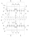
- FIG. 1 is a view conceptually showing the installation structure of a linear motor for an elevator according to an embodiment of the present invention
- Figure 2 is a cross-sectional view taken along the line "A-A" of Figure 1 to explain the internal structure of the elevator linear motor according to an embodiment of the present invention
- FIG. 3 is a view conceptually showing the configuration of a stator module of an elevator linear motor according to an embodiment of the present invention
- FIG. 4 is a view conceptually showing the configuration of the mover module of the elevator linear motor according to an embodiment of the present invention
- FIG. 6 and 7 is a diagram conceptually showing the magnetic flux flow state of the linear motor for an elevator according to an embodiment of the present invention
- FIGS. 8 to 10 are views exemplarily showing various forms of the mover module according to an embodiment of the present invention.
- FIG. 11 is a view for explaining a magnetic flux flow method for the basic structure of a linear motor according to an embodiment of the present invention
- FIG. 12 is a view for explaining a problem of magnetic flux flow that may occur in the basic structure of a linear motor according to an embodiment of the present invention
- FIG. 13 is a view for explaining the basic structure of a linear motor that solves the problem of magnetic flux flow shown in FIG. 12;
- FIG. 14 is a view for explaining the permanent magnet arrangement structure of the mover module according to an embodiment of the present invention.
- 17 is a view for explaining the relationship between the gap size of the stator module and the number of permanent magnets according to an embodiment of the present invention.
- FIG. 18 is a view for explaining a winding method for the armature winding of the mover module according to an embodiment of the present invention
- 19 is a view schematically showing another form of a linear motor according to an embodiment of the present invention.
- FIG. 1 is a diagram conceptually showing an installation structure of an elevator linear motor according to an embodiment of the present invention
- FIG. 2 is a view illustrating an internal structure of an elevator linear motor according to an embodiment of the present invention
- 3 is a cross-sectional view taken along the line “AA”
- FIG. 3 is a diagram conceptually showing a configuration for a stator module of an elevator linear motor according to an embodiment of the present invention
- FIG. 4 is a view showing an embodiment of the present invention.
- It is a diagram conceptually showing the configuration of the mover module of the linear motor for an elevator according to the present invention
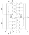
- FIG. 5 is a view for explaining the principle of magnetic flux flow of the linear motor for an elevator according to an embodiment of the present invention.
- the linear motor for an elevator is a device capable of more conveniently performing an installation operation and a maintenance operation, and the stator module 40 that is long disposed in a hoistway along the traveling direction of the elevator car 10 And, it comprises a mover module 50 coupled to the elevator car 10 so as to face each other on both sides of the stator module 40 along the longitudinal direction of the stator module 40.
- a hoistway in which the elevator car 10 can move is installed inside the building.
- the hoistway may be installed not only vertically but also in a horizontal direction and inclined direction.
- the elevator car 10 moves along the hoistway through a linear motor or the like.
- a guide rail 30 may be installed on the hoistway wall 20 of the hoistway along the direction of the hoistway, and when the guide rail 30 is installed, the elevator car 10 moves along the guide rail 30 within the hoistway However, at this time, the elevator car 10 is moved by the linear motor 60.
- the linear motor 60 includes a stator module 40 and a mover module 50, and the stator module 40 is long installed in the hoistway along the traveling direction of the elevator car 10.
- the stator module 40 may be directly installed on the hoistway wall 20 of the hoistway, and when the guide rail 30 is installed on the hoistway wall 20, it is formed long along the guide rail 30 to guide rail 30 It can be installed in a form that is coupled to one end of the.
- the mover module 50 is coupled and fixed to the elevator car 10 to be located on both sides of the stator module 40 along the longitudinal direction of the stator module 40.
- the propulsive force is generated by the electromagnetic force generated between the stator module 40 and the mover module 50, and the mover module 50 and the elevator car 10 move along the stator module 40 by the propulsion force.
- Stator module 40 according to an embodiment of the present invention is installed in a form arranged in a row spaced apart a plurality of stator 100 along the guide rail 30 to have a certain gap (d).
- the stator is not integrally formed, but the stator 100 is provided in a plurality of relatively short lengths and installed in a separate form having a certain gap d.
- the mover module 50 and the stator module 40 are formed such that the flow of magnetic flux formed through the mover module 50 and the stator module 40 does not pass through the gap d of the stator 100. Is formed.
- the flux flow through the mover module 50 and the stator module 40 is formed so as not to pass through the gap d of the stator 100, so that even if the gap d exists in the stator module 40, The magnetic flux flow stably occurs without interruption or sudden drop, and the propulsion by electromagnetic force is stably generated.
- stator module 40 that is installed along the hoistway is separately installed by a plurality of stators 100, it is not only easy to manufacture and install the stator module 40, but also can significantly shorten the installation work time. .
- stator module since the stator module is installed as one unit in the entire section of the hoistway along the guide rail, it is necessary to connect all the stator module connection parts by welding or the like during the installation process. Thereafter, even in the case of repair and replacement work for the stator module, since the repair work must be performed in a manner such as cutting a portion of the integral stator module, there is a problem that the work is very difficult and difficult.
- the stator module 40 separates and installs a plurality of stators 100 in a form having a certain gap (d), so that a separate connection operation is unnecessary during the installation operation.
- a separate connection operation is unnecessary during the installation operation.
- it is easy to correct the error through adjustment of the gap (d) and even when repairing and replacing the stator module 40, the stator 100 in some sections can be simply partially removed and replaced for maintenance work and other checks. Work can also be done very quickly and conveniently.
- the stator module 40 when the stator module 40 is integrally formed long, the amount of thermal deformation of the stator module 40 increases due to a change in temperature conditions according to the environment, and accordingly, a dimensional change occurs, resulting in a problem in driving performance when driving the elevator.
- the stator module 40 since the stator module 40 is separately installed through a plurality of stators 100, the amount of heat distortion can be compensated by the gap d even if thermal deformation occurs. The dimensional change can be minimized, and accordingly, stable driving performance can be maintained at all times.
- each stator 100 may be formed in the same form, and each stator 100 is a central field iron core formed long along the traveling direction of the elevator car 10 It may be configured to include a first protruding portion 120 and a second protruding portion 130, which are respectively protruded on both sides of the central field iron core portion 110 and 110.
- the first protruding portion 120 and the second protruding portion 130 are arranged to be offset from each other along the width direction of the central field iron core portion 110. More specifically, the first protrusion 120 is formed to protrude on one side of the central field iron core 110, and the second protrusion 130 protrudes on the other side of the center field iron core 110. It is formed, the first protrusion 120 and the second protrusion 130 is formed in the same protruding shape.
- the plurality of first protruding parts 120 are spaced apart to have the same disposition gap 2P, and the plurality of second protruding parts 130 are the same disposition spacing so as to be located between the spaced apart spaces of the first protruding parts 120 (2P).
- the second protrusion 130 is located in the middle of the separation interval of the first protrusion 120, the placement distance of the first protrusion 120 and the second protrusion 130 is also the same placement interval P Have
- the stator 100 having the plurality of first protruding parts 120 and the second protruding part 130 has a gap d, and a plurality of stators are arranged in line, and the spacing (2P) of the first protruding parts 120 is arranged. ) Are arranged to remain the same between the two stators 100 adjacent to each other.
- the arrangement spacing 2P of the second protrusion 130 is likewise arranged to remain the same between the two stator 100 adjacent to each other.
- the spacing between the first protrusion 120 and the second protrusion 130 that are disposed to be offset from each other is P
- the spacing between the poles 130 is 2P.
- the bottom first protrusion 120 of the upper stator 100 among the stators 100 adjacent to each other and the lower side The spacing between the uppermost second protruding parts 130 of the stator 100 remains the same as P, and the lowermost second protruding part 130 of the upper stator 100 among the stators 100 adjacent to each other and the lower side
- the spacing between the second protruding poles 130 at the top of the stator 100 is maintained at 2P.
- the gap d between the stators 100 is predetermined in a plurality of stator 100 manufacturing steps, and by setting and installing the gap d according to a predetermined gap d dimension during the stator 100 installation operation, although it is possible to perform a normal installation operation, at this time, an error or the like may occur, so that the spacing (P, 2P) between the first protruding part 120 and the second protruding part 130 is controlled by adjusting the gap d. ) Can be kept constant.
- the gap (d) between the stator 100 which is predetermined in the manufacturing step, is such that the first protrusion 120 and the second protrusion 130 are not removed and some of them exist at a predetermined placement interval P. It may be determined to be smaller than P, which is an arrangement interval between the protrusion 120 and the second protrusion 130. That is, the gap d between the stators 100 may be determined in the range of (0 ⁇ d ⁇ P).
- the mover module 50 is disposed opposite to each other on the stator module 40, and the intermediate slot 203 is formed in the middle region and the stator module 40 is provided in both regions around the middle slot 203.
- Magnet armature including at least one permanent magnet (210) disposed to have the same spacing (P, 2P) as the first and second protrusions (120,130) and the armature iron core through the intermediate slot (203) It may be configured to include an armature winding (230,240) wound on (201,202).
- the two armature iron cores 201 and 202 face each other in a form in which the first armature iron core 201 is disposed on one side of the stator module 40 and the second armature iron core 202 is disposed on the other side of the stator module 40. Can be arranged.
- the magnet modules M are formed to face each other on the first and second mover teeth 204 and 205 respectively formed on the two armature iron cores 201 and 202, respectively.
- the permanent magnet 210 having the same polarity (N-pole or S-pole) and the permanent magnet 210 and the protruding poles 220 disposed in the adjacent regions are the first and second protruding portions 120 and 130 It may be configured to be arranged in a row alternately with each other at the same arrangement interval as the gap pitch P, which is an interval.
- the permanent magnets 210 having the same polarity (N-pole) may be arranged in a line to be spaced apart from each other, and may be configured such that the protruding pole 220 as a simple magnetic material is formed in the region therebetween, wherein the protruding pole 220 is The polarity (N pole) and the opposite polarity (S pole) of the permanent magnet 210 are displayed.
- the magnet module M may be configured such that permanent magnets 210: 211, 212 having different polarities (N poles, S poles) are alternately arranged at the same arrangement interval as the protruding pitch P. (See Figure 8).
- the permanent magnet 210 adjacent to the second mover tooth 205 and the plurality of permanent magnets mounted on the second mover tooth 205 The arrangement interval between the permanent magnets 210 adjacent to the first mover teeth 204 of 210 is formed to be n times (here, n is a natural number) of the protruding pitch P (see FIG. 14).
- n is a natural number
- the spacing between the permanent magnets 210 located may be formed of 3P, which is three times the protruding pitch P.
- the permanent magnet 210 mounted on the first mover tooth 204 and the permanent magnet 210 mounted on the second mover tooth 205 include the first protrusion 120 and the second stone of the stator 100.
- the poles 130 have different relative positions.
- the permanent magnet 210 located in the first mover tooth 204 of the armature iron cores 201 and 202 is positioned on the same straight line as the second protruding part 130, and the armature The permanent magnets 210 located on the second mover teeth 205 of the iron cores 201 and 202 are positioned on the same straight line as the first protrusion 120.
- the flow of magnetic flux by permanent magnets mounted on the first and second mover teeth 204 and 205 of the two armature iron cores 201 and 202 is shown as shown in FIG. 5. That is, since the permanent magnet 210 mounted on the first mover teeth 204 of the second armature iron core 202 is an N-pole, it is formed in a form in which magnetic flux flows out from the permanent magnet 210.
- the permanent magnet 210 of the first armature iron core 201 also exhibits an N-pole, the magnetic flux flow does not flow into the permanent magnet 210 of the first armature iron core 201, and toward the upper and lower protruding poles 220 side. Inflow.
- the protruding pole 220 is relatively closer to the first protruding portion 120, the magnetic flux flows from the first protruding portion 120 toward the protruding pole 220, in this case, the protruding pole 220 is a permanent magnet It acts as the S pole, which is a different polarity from the 210.
- the flow of magnetic flux from the permanent magnet 210 of the second armature iron core 202 is the same polarity (N pole) of the permanent magnet 210 of the first armature core 201, forces that repel each other generate magnetic flux. The branching process of the flow is made more smoothly, and accordingly, the flux flow of the first armature 201 to the protruding pole 220 is made more smoothly.
- the armature windings 230 and 240 are wound in opposite directions from the first mover tooth 204 and the second mover tooth 205.
- Intermediate slots 203 are formed in the center of the mutually opposing surfaces of the two armature iron cores 201 and 202, and the first mover teeth 204 and the second mover teeth 205 are formed on both sides around the middle slot 203.
- the armature windings 230 and 240 may be wound in opposite directions to each other in a form surrounding the first mover tooth 204 and the second mover tooth 205 through the intermediate slot 203.
- Each armature winding (230,240) may be configured to be separately connected in series after being formed in an independently wound form.
- the magnetic flux flow from the plurality of permanent magnets 210 mounted on the second mover teeth 205 of the second armature core 202 It is discharged and flows into the second protruding part 130 of the stator 100, and each magnetic flux flow is branched from the central field iron core part 110 of the stator 100 and then first through the first protruding part 120. It is introduced into the armature iron core 201. At this time, the permanent magnet 210 mounted on the second mover tooth 205 of the first armature iron core 201 flows into the region of the protruding electrode 220. Since the branching and flow of the magnetic flux is based on the principle described with reference to FIG. 5, detailed description is omitted here.
- magnetic flux flow is also discharged from the plurality of permanent magnets 210 mounted on the first mover teeth 204 of the first armature core 201 to flow into the first protrusion 120 of the stator 100,
- Each magnetic flux flow is branched from the central field iron core portion 110 of the stator 100 and then flows into the second armature iron core 202 through the second protruding portion 130. At this time, it flows into the region of the protrusion 220 between the permanent magnets 210 mounted on the first mover teeth 204 of the second armature core 202.
- the flow of magnetic flux is reversed in the first mover value 204 and the second mover value 205 of the armature iron cores 201 and 202 according to the flow of the magnetic flux, and correspondingly, the winding direction of the armature windings 230 and 240 is the first mover value. Since 204 and the second mover value 205 are opposite, the mover module 50 generates the same propulsion force by electromagnetic force.
- the flow of magnetic flux discharged from the permanent magnet 210 of one armature iron core 201,202 is branched from the stator 100 and flows into the other armature iron core 201,202 through the protruding pole portions 120,130.
- the stator 100 is separated through the gap d Even if it is, the magnetic flux flow through the gap d of the stator 100 is prevented, and even if a magnetic flux flow through the gap d occurs, it is very negligible, which is a negligible level. Therefore, even if the stator module 40 according to an embodiment of the present invention separates and installs a plurality of stators 100 through the gap d, the traveling performance of the linear motor is stably maintained because there is no influence on magnetic flux flow. .
- FIG. 7 shows a magnetic flux flow in a state in which the mover module 50 moves with the elevator car 10 by a P interval in the right direction based on the state shown in FIG. 6. 6, the magnetic flux flow appears in the same principle as in FIG. 6, but the overall direction of the magnetic flux flow is formed in the clockwise direction in FIG. 6, while in FIG. In this process, since the direction of the current flowing through the armature windings 230 and 240 is changed, the direction of propulsion by electromagnetic force is always maintained the same regardless of the moving state of the mover module 50.
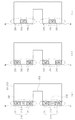
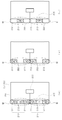
- FIG 8 to 10 are views exemplarily showing various forms of the mover module according to an embodiment of the present invention.
- the mover module 50 is mounted on the armature iron cores 201 and 202 having the first and second mover teeth 204 and 205 and the first and second mover teeth 204 and 205 as described above. It comprises a magnet module (M) including at least one permanent magnet 210 and the armature winding (230).
- M magnet module
- the magnet module M may be configured in a form in which permanent magnets 210: 211, 212 having different polarities (N-pole, S-pole) are alternately arranged as shown in FIG. 8 (a). .
- a permanent magnet 210 having the same polarity (N-pole) with each other and a protruding electrode 220 disposed in a region adjacent to the permanent magnet 210 are provided. It may be configured in a form arranged alternately with each other. In this case, the arrangement structure of the permanent magnet 210 and the protruding electrode 220 may be set differently as shown in (b) and (c) of FIG. 8 in the first and second mover values 204 and 205.
- the permanent magnet 210 and the protruding poles 220 are arranged to have the same spacing as the protruding pole pitch P.
- the widths of the permanent magnets 210 and the protruding poles 220 are also as shown in FIG. 8. It is formed in the same manner as the protruding pole pitch P, and the plurality of permanent magnets 210 and the protruding poles 220 may be disposed in contact with each other.
- the widths of the permanent magnets 210 and the protruding poles 220 are smaller than the protruding pitch P, so that the plurality of permanent magnets 210 and the protruding poles 220 do not contact each other. It can also be arranged spaced apart.
- An intermediate slot 203 is formed in an intermediate region of the armature iron cores 201 and 202, and first and second mover teeth 204 and 205 are formed on both sides around the intermediate slot 203, where the intermediate slot 203 is formed.
- 8 and 9 may be formed in one side open form (open type), as shown in Figure 10 may be formed in a form that does not open to one side (closed type). .
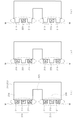
- FIG. 11 is a diagram for explaining a magnetic flux flow method for the basic structure of a linear motor according to an embodiment of the present invention
- FIG. 12 is a magnetic flux flow that may occur in the basic structure of a linear motor according to an embodiment of the present invention
- 13 is a view for explaining the basic structure of a linear motor that solves the problem of magnetic flux flow shown in FIG. 12.
- At least one permanent magnet 210 having different polarities is respectively provided to the first and second moving teeth 204 and 205, respectively.
- the structure in which two are mounted becomes the basic structure.
- the magnetic flux flow represents the flow circulating through the permanent magnet 210 and the stator module 40 of the first and second mover teeth 204,205 as shown in the direction of the arrow in FIG. Since this magnetic flux flow is the same principle as described in FIGS. 1 to 7, detailed descriptions are omitted here.
- the gap (d) is present in the stator module 40 according to an embodiment of the present invention, as shown in (a) and (b) of FIG. 12, wherever the gap (d) is formed A problem arises in that the magnetic flux flows through the gap (d). Since the magnetic flux flow rapidly decreases in the process of passing through the gap (d), when such a magnetic flux flow occurs, the thrust force of the linear motor cannot be stably generated. Therefore, when the stator module 40 is installed in a form in which a gap d exists using a plurality of stators 100, the magnetic flux flow must be configured to be smoothly formed without passing through the gap d.
- the number of permanent magnets 210 having different polarities (N-pole, S-pole) respectively mounted on the first and second movable teeth 204 and 205 is at least 3
- N-pole, S-pole the number of permanent magnets 210 having different polarities
- the first and second mover teeth 204 and 205 are shown with respect to a structure in which permanent magnets 210: 211 and 212 of different polarities (N-pole and S-pole) are arranged in a line.
- the protruding poles 220 substantially function as the S-poles, and in this case, the same principle As a result, a stable magnetic flux flow is formed.
- FIGS. 15 and 16 is a magnetic flux flow generated in the arrangement structure of the permanent magnet according to an embodiment of the present invention It is a diagram illustrated illustratively.
- Armature iron cores 201 and 202 are formed with intermediate slots 203 in the intermediate region as described above, and the first and second mover teeth protruding toward the stator module 40 in both regions around the intermediate slot 203 ( 204 and 205 are formed, and the magnet module M is mounted on the first and second movable teeth 204 and 205.
- the first and second mover teeth 204 and 205 are formed in the same shape as the protruding height and width projecting toward the stator module 40, and thus, the permanent magnet 210 mounted on the first and second mover teeth 204 and 205 ) Are the same.
- the magnet module M is formed of the permanent magnet 210 and the protruding pole 220, similarly, the total number of the permanent magnet 210 and the protruding pole 220 is mutually different from the first and second mover values 204 and 205. same.
- Arrangement of the first and second mover teeth 204 and 205 is the distance between the centerline of the first mover tooth 204 and the centerline of the second mover tooth 205 according to the shape of the first and second mover teeth 204 and 205. It can be defined as an interval tooth pitch (Pt), the tooth pitch (Pt) is formed differently depending on whether the polarity arrangement state of the permanent magnet 210 in the first and second mover teeth (204,205) are the same as each other do.
- the tooth pitch Pt is equal to that of the protruding pitch P. It is formed of (2n-1) times (where n is a natural number of 2 or more), and as shown in FIG. 14 (b), the polarity of the permanent magnet 210 in the first and second moving teeth 204 and 205 When is different from each other, the tooth pitch Pt is formed by (2n) times (where n is a natural number of 2 or more) of the protruding pitch P.
- the tooth pitch Pt is formed by an odd multiple of three or more of the protruding pitch P
- the first and second are different from each other, the tooth pitch Pt is formed by an even multiple of 4 or more of the protruding pitch P.
- the magnetic flux flow through the permanent magnet 210 is formed so as not to pass through the gap d, thereby forming a stable magnetic flux flow.
- the second mover value of the permanent magnet 210 mounted on the first mover tooth 204 If the permanent magnets 210 adjacent to the 205 and the permanent magnets 210 adjacent to the first moving teeth 204 of the permanent magnets 210 mounted on the second moving teeth 205 have different polarities, the corresponding two The spacing between the permanent magnets 210 is formed by (2m) times (where m is a natural number) of the protruding pitch P.
- the permanent magnets 210 of the first mover teeth 204 and the permanent magnets 210 of the second mover teeth 205 are relative to the first and second protrusions 120 and 130 of the stator module 40.
- the relative positions of the elevator cars 10 in the traveling direction are arranged differently. That is, while the N-pole permanent magnet 211 of the first mover tooth 204 is located on the same horizontal line as the second protrusion 130, the N-pole permanent magnet 211 of the second mover tooth 205 is made of 1 is located on the same horizontal line as the protrusion 120. Accordingly, as described in FIGS. 6 and 7, a stable magnetic flux flow is generated as a whole.
- the magnet module (M) is formed in a form in which the permanent magnet 210 and the protruding pole 220 are alternately arranged in a row, instead of the S-pole permanent magnet 210 of FIG. 14, the protruding pole 220 ), The same arrangement is applied.
- the mover module 50 shown in FIG. 15 includes first and In the case where the polarity arrangement state of the permanent magnet 210 is the same in the second mover teeth 204 and 205, and the tooth pitch Pt is 5P, which is 5 times the protrusion pitch P, the magnetic flux flow passes through the gap d. It does not show a stable flow. At this time, the spacing between the permanent magnets 210 adjacent to each other in the first and second moving teeth 204 and 205 is 2P, which is an even multiple of the protruding pitch P.
- the magnetic flux flow does not pass through the gap d and shows a stable flow.
- the spacing between the permanent magnets 210 adjacent to each other in the first and second movable teeth 204 and 205 is P, which is an odd multiple of the protruding pitch P.
- 17 is a view for explaining the relationship between the gap size of the stator module and the number of permanent magnets according to an embodiment of the present invention.
- the gap d between the plurality of stators 100 of the stator module 40 is preferably set to be smaller than the protruding pitch P, as described with reference to FIGS. 1 to 7. It might be.
- the first and second protrusions 120 and 130 are spaced apart at a pitch P interval, and in this case, the protrusion widths bw of the first and second protrusions 120 and 130 are all the same.
- the number of permanent magnets 210 mounted on the first and second mover teeth 204 and 205 is respectively set to at least three, and the gap d between the stator 100 is first and first. 2
- the width of the protrusions 120 and 130 is less than bw, as shown in FIG. 13, even when the number of permanent magnets 210 is three, magnetic flux flow is stably performed. That is, when the gap d between the stator 100 is installed to be less than the width bw of the first and second protrusions 120 and 130, the number of permanent magnets 210 may be set to three or more.
- the minimum number of permanent magnets 210 is set according to the following rules.
- the number of permanent magnets 210 is set to (n + 4) or more.
- n is an integer of 0 or more
- P is the pitch of the protruding poles
- bw is the width of the first and second protruding portions
- d is the gap.
- the gap d between the stators is greater than the width bw of the first protruding portion 120 or the second protruding portion 130, and the width bw and the protruding pitch P ),
- the number of permanent magnets 210 is set to at least four, and in this case, the magnetic flux flow is stably formed in a form that does not pass through the gap d.
- permanent magnets 210 having different polarities are alternately arranged in a row in the first and second movable teeth 204 and 205, but the same polarities ( The same applies to the case where the permanent magnet 210 having the N pole) and the protruding pole 220 are alternately arranged in a row.
- the total number of permanent magnets 210 and protrusions 220 is set to (n + 4) or more, , If the gap (d) between the stator 100 is installed less than the width (bw) of the first and second protrusions 120 and 130, the total number of permanent magnets 210 and protrusions 220 is set to 3 or more do.
- magnetic flux flow can be stably formed in a manner that does not pass through the gap d. .
- Figure 19 is a view schematically showing another form of a linear motor according to an embodiment of the present invention to be.
- the winding method for the armature winding 230 of the mover module 50 is exemplarily illustrated. Unlike that shown in FIGS. 2 and 4, the armature winding 230 has an armature iron core through an intermediate slot 203. It may be wound in the form of wrapping (201,202) in the transverse direction.
- the winding method may be variously changed.
- the linear motor includes two armature iron cores 201 and 202, a magnet module M, and a mover module 50: 50a including an armature winding 230 , 50b, 50c) may be provided to be arranged in a line along the traveling direction of the elevator car.
- Each of the mover modules 50a, 50b, and 50c can be used as a three-phase device having three voltages shifted by 120 ° from each other, and in addition, two or more mover modules 50 are provided and mutual electric angles are provided. It can be used as an electric motor that consumes polyphase alternating current by displaced or a polyphase device that generates multiphase electromotive force.
- one mover module 50 may operate by single-phase AC voltage and current or generate single-phase AC electromotive force.
Abstract
La présente invention concerne un moteur linéaire pour un ascenseur, une pluralité de stators installés dans une cage d'ascenseur étant installés séparément de telle sorte que des espaces sont présents entre eux. Par conséquent : non seulement la fabrication et l'installation sont pratiques, mais le temps d'installation peut être significativement réduit ; non seulement une opération de connexion séparée n'est pas requise pendant l'installation, mais les erreurs peuvent être facilement corrigées par réglage des espaces entre les stators ; et il est possible de retirer et de remplacer simplement une partie des stators dans certaines sections même lors de la réparation ou du remplacement des stators. Par conséquent, la maintenance et les autres opérations d'inspection peuvent être effectuées de manière très rapide et pratique.
Applications Claiming Priority (6)
| Application Number | Priority Date | Filing Date | Title |
|---|---|---|---|
| KR10-2018-0107597 | 2018-09-10 | ||
| KR1020180107599A KR102024474B1 (ko) | 2018-09-10 | 2018-09-10 | 엘리베이터용 리니어 모터 |
| KR10-2018-0107598 | 2018-09-10 | ||
| KR1020180107597A KR102076420B1 (ko) | 2018-09-10 | 2018-09-10 | 엘리베이터용 리니어 모터 |
| KR10-2018-0107599 | 2018-09-10 | ||
| KR1020180107598A KR102024473B1 (ko) | 2018-09-10 | 2018-09-10 | 엘리베이터용 리니어 모터 |
Publications (1)
| Publication Number | Publication Date |
|---|---|
| WO2020054911A1 true WO2020054911A1 (fr) | 2020-03-19 |
Family
ID=69776782
Family Applications (1)
| Application Number | Title | Priority Date | Filing Date |
|---|---|---|---|
| PCT/KR2018/014332 WO2020054911A1 (fr) | 2018-09-10 | 2018-11-21 | Moteur linéaire pour ascenseur |
Country Status (1)
| Country | Link |
|---|---|
| WO (1) | WO2020054911A1 (fr) |
Citations (5)
| Publication number | Priority date | Publication date | Assignee | Title |
|---|---|---|---|---|
| JPH0543166A (ja) * | 1991-08-07 | 1993-02-23 | Mitsubishi Electric Corp | リニアモータエレベーター |
| JPH0967075A (ja) * | 1995-08-30 | 1997-03-11 | Mitsubishi Electric Corp | リニアモータ駆動エレベーター |
| JPH09272677A (ja) * | 1996-04-04 | 1997-10-21 | Mitsubishi Electric Corp | リニアモータエレベーターの駆動装置 |
| JP2007318839A (ja) * | 2006-05-23 | 2007-12-06 | Okuma Corp | リニアモータ |
| KR20100098432A (ko) * | 2007-12-11 | 2010-09-06 | 인벤티오 아게 | 수직방향 및 수평방향으로 이동할 수 있는 승강기 카를 구비한 승강기 시스템 |
-
2018
- 2018-11-21 WO PCT/KR2018/014332 patent/WO2020054911A1/fr active Application Filing
Patent Citations (5)
| Publication number | Priority date | Publication date | Assignee | Title |
|---|---|---|---|---|
| JPH0543166A (ja) * | 1991-08-07 | 1993-02-23 | Mitsubishi Electric Corp | リニアモータエレベーター |
| JPH0967075A (ja) * | 1995-08-30 | 1997-03-11 | Mitsubishi Electric Corp | リニアモータ駆動エレベーター |
| JPH09272677A (ja) * | 1996-04-04 | 1997-10-21 | Mitsubishi Electric Corp | リニアモータエレベーターの駆動装置 |
| JP2007318839A (ja) * | 2006-05-23 | 2007-12-06 | Okuma Corp | リニアモータ |
| KR20100098432A (ko) * | 2007-12-11 | 2010-09-06 | 인벤티오 아게 | 수직방향 및 수평방향으로 이동할 수 있는 승강기 카를 구비한 승강기 시스템 |
Similar Documents
| Publication | Publication Date | Title |
|---|---|---|
| WO2012026685A2 (fr) | Moteur linéaire | |
| WO2011049298A2 (fr) | Moteur linéaire | |
| EP3476021A1 (fr) | Stator et moteur le comportant | |
| US20190214896A1 (en) | A linear electric machine and a power electronic converter for controlling the linear electric machine | |
| CN104272568A (zh) | 直线同步电动机 | |
| WO2022164070A1 (fr) | Appareil de test pour excitateur supraconducteur sans contact de type à commande de courant actif ayant un aimant hybride installé à l'intérieur de celui-ci, et machine rotative supraconductrice à haute température l'utilisant | |
| CN105358466B (zh) | 用于自推进电梯的定子结构 | |
| WO2020054911A1 (fr) | Moteur linéaire pour ascenseur | |
| WO2013085231A1 (fr) | Rotor comprenant des aimants permanents ayant des épaisseurs différentes et moteur le comprenant | |
| WO2018101638A1 (fr) | Ensemble capot, moteur et dispositif de direction électrique le comprenant | |
| KR102076420B1 (ko) | 엘리베이터용 리니어 모터 | |
| KR102024474B1 (ko) | 엘리베이터용 리니어 모터 | |
| WO2014109499A1 (fr) | Induit de moteur linéaire sans fer et moteur linéaire sans fer mettant en œuvre ledit induit | |
| WO2020166960A1 (fr) | Purificateur d'air à plasma dbd et dispositif de réduction de gaz d'échappement | |
| WO2023182749A1 (fr) | Système de regroupement de batteries utilisant un dispositif de génération d'énergie configuré pour générer de l'énergie de manière successive et indépendante | |
| WO2017204425A1 (fr) | Équipement électrique à aimant permanent et à longueur de pôle magnétique non uniforme | |
| KR102024473B1 (ko) | 엘리베이터용 리니어 모터 | |
| WO2020050535A1 (fr) | Moteur | |
| WO2021141299A1 (fr) | Moteur | |
| WO2020149626A1 (fr) | Rotor et moteur comportant le rotor | |
| US11349366B2 (en) | Winding overhang | |
| WO2020085744A1 (fr) | Moteur | |
| KR100275574B1 (ko) | 로플리스 엘리베이터 및 그 구동방법 | |
| WO2022231153A1 (fr) | Moteur | |
| WO2023224144A1 (fr) | Moteur linéaire |
Legal Events
| Date | Code | Title | Description |
|---|---|---|---|
| 121 | Ep: the epo has been informed by wipo that ep was designated in this application |
Ref document number: 18933032 Country of ref document: EP Kind code of ref document: A1 |
|
| NENP | Non-entry into the national phase |
Ref country code: DE |
|
| 122 | Ep: pct application non-entry in european phase |
Ref document number: 18933032 Country of ref document: EP Kind code of ref document: A1 |