WO2020054846A1 - Internal combustion engine - Google Patents
Internal combustion engine Download PDFInfo
- Publication number
- WO2020054846A1 WO2020054846A1 PCT/JP2019/036087 JP2019036087W WO2020054846A1 WO 2020054846 A1 WO2020054846 A1 WO 2020054846A1 JP 2019036087 W JP2019036087 W JP 2019036087W WO 2020054846 A1 WO2020054846 A1 WO 2020054846A1
- Authority
- WO
- WIPO (PCT)
- Prior art keywords
- internal combustion
- combustion engine
- crankshaft
- tensioner
- wall
- Prior art date
Links
Images


Classifications
-
- F—MECHANICAL ENGINEERING; LIGHTING; HEATING; WEAPONS; BLASTING
- F01—MACHINES OR ENGINES IN GENERAL; ENGINE PLANTS IN GENERAL; STEAM ENGINES
- F01L—CYCLICALLY OPERATING VALVES FOR MACHINES OR ENGINES
- F01L1/00—Valve-gear or valve arrangements, e.g. lift-valve gear
- F01L1/02—Valve drive
-
- F—MECHANICAL ENGINEERING; LIGHTING; HEATING; WEAPONS; BLASTING
- F02—COMBUSTION ENGINES; HOT-GAS OR COMBUSTION-PRODUCT ENGINE PLANTS
- F02B—INTERNAL-COMBUSTION PISTON ENGINES; COMBUSTION ENGINES IN GENERAL
- F02B67/00—Engines characterised by the arrangement of auxiliary apparatus not being otherwise provided for, e.g. the apparatus having different functions; Driving auxiliary apparatus from engines, not otherwise provided for
- F02B67/04—Engines characterised by the arrangement of auxiliary apparatus not being otherwise provided for, e.g. the apparatus having different functions; Driving auxiliary apparatus from engines, not otherwise provided for of mechanically-driven auxiliary apparatus
- F02B67/06—Engines characterised by the arrangement of auxiliary apparatus not being otherwise provided for, e.g. the apparatus having different functions; Driving auxiliary apparatus from engines, not otherwise provided for of mechanically-driven auxiliary apparatus driven by means of chains, belts, or like endless members
-
- F—MECHANICAL ENGINEERING; LIGHTING; HEATING; WEAPONS; BLASTING
- F02—COMBUSTION ENGINES; HOT-GAS OR COMBUSTION-PRODUCT ENGINE PLANTS
- F02F—CYLINDERS, PISTONS OR CASINGS, FOR COMBUSTION ENGINES; ARRANGEMENTS OF SEALINGS IN COMBUSTION ENGINES
- F02F1/00—Cylinders; Cylinder heads
-
- F—MECHANICAL ENGINEERING; LIGHTING; HEATING; WEAPONS; BLASTING
- F02—COMBUSTION ENGINES; HOT-GAS OR COMBUSTION-PRODUCT ENGINE PLANTS
- F02F—CYLINDERS, PISTONS OR CASINGS, FOR COMBUSTION ENGINES; ARRANGEMENTS OF SEALINGS IN COMBUSTION ENGINES
- F02F7/00—Casings, e.g. crankcases or frames
-
- F—MECHANICAL ENGINEERING; LIGHTING; HEATING; WEAPONS; BLASTING
- F16—ENGINEERING ELEMENTS AND UNITS; GENERAL MEASURES FOR PRODUCING AND MAINTAINING EFFECTIVE FUNCTIONING OF MACHINES OR INSTALLATIONS; THERMAL INSULATION IN GENERAL
- F16H—GEARING
- F16H7/00—Gearings for conveying rotary motion by endless flexible members
- F16H7/08—Means for varying tension of belts, ropes, or chains
- F16H7/10—Means for varying tension of belts, ropes, or chains by adjusting the axis of a pulley
- F16H7/12—Means for varying tension of belts, ropes, or chains by adjusting the axis of a pulley of an idle pulley
Definitions
- the present invention relates to a transmission component that is connected to a crankshaft and a camshaft, moves along an annular path, and transmits torque from the crankshaft to the camshaft, and displaces along a virtual plane orthogonal to the rotation axis of the crankshaft.
- a tensioner that freely contacts a transmission component to adjust the tension of the transmission component, and a tensioner lifter that is separably attached to the engine body and applies a load to the tensioner along an imaginary plane perpendicular to the rotation axis of the crankshaft.
- an internal combustion engine comprising:
- Patent Document 1 discloses a tensioner that is attached to an internal combustion engine and swings around a swing axis parallel to a rotation axis of a crankshaft.
- the tensioner contacts the timing chain (transmission component) to adjust the tension of the timing chain.
- the chain adjuster (tensioner lifter) generates a load for holding the tensioner at a fixed position along an imaginary plane orthogonal to the rotation axis of the crankshaft.
- the chain adjuster is attached with bolts to the inner wall of the crankcase that forms the engine body.
- a mounting surface formed by a plane perpendicular to the rotation axis of the crankshaft is formed on the inner wall surface of the crankcase.
- the present invention has been made in view of the above circumstances, and has as its object to provide an internal combustion engine capable of securing a predetermined length of a spring and maintaining tension more appropriately than ever.
- an engine body that supports a crankshaft and a camshaft having mutually parallel rotation axes, and is connected to the crankshaft and the camshaft to move along an annular path and move along the annular path.
- a transmission component that transmits a rotational force from a crankshaft to the camshaft; a tensioner that adjusts the tension of the transmission component by contacting the transmission component displaceably along an imaginary plane orthogonal to the rotation axis;
- a tensioner lifter attached to the engine main body and applying a load to the tensioner along the virtual plane, wherein the inner wall surface of the engine main body includes a tensioner lifter as viewed in an axial direction of a crankshaft.
- a concave portion is arranged so as to overlap a part.
- the tensioner lifter is fixed to the engine body to define a cylindrical section, and is inserted into the cylinder so as to be axially displaceable.
- Forming an oil chamber in the tubular portion between the closed end of the tubular portion, and contacting the tensioner at the upper end protruding from the tubular portion to apply tension to the tensioner, from the upper end of the tubular portion A push rod having an oil passage communicating with the oil chamber; and a large-diameter portion disposed above the cylindrical portion and opening upward while having a larger diameter than the cylindrical portion.
- the engine body has a wall surface that supports the tensioner lifter and has an oil supply port that opens above the enlarged diameter portion.
- the enlarged diameter portion opens toward the wall of the engine body and is coupled to the wall of the engine body.
- the wall has a U-shaped wall projecting from the wall and defining a space that is open upward continuously to the space in the enlarged diameter portion. It is formed.
- a rib protruding from the wall below the oil supply port is formed on the wall.
- the rib extends toward the crankshaft from above the enlarged diameter portion to the front and downward.
- the rib is formed in a curved shape that is displaced upward as going forward.
- an encircling rib that opens downward around the oil supply port is formed on the wall surface.
- the tensioner lifter since the tensioner lifter enters the recess formed in the inner wall surface of the engine body, the length of the tensioner lifter can be secured without shifting the position of the wall of the engine body. Even when the tensioner lifter is long, the tensioner lifter can be well accommodated in the engine body. Enlargement of the engine body can be avoided.
- the space around the push rod is expanded by the enlarged diameter portion, so that the inflow of oil around the push rod can be promoted.
- the oil path can be sufficiently supplied with oil.
- the tensioner lifter can be sufficiently supplied with oil from the oil supply port.
- oil transmitted through the wall of the engine body can be introduced into the tensioner lifter.
- the oil can flow around the push rod more effectively.
- the oil flowing out of the oil supply port can be supplied not only to the tensioner lifter but also to other parts along the rib. Oil can be used efficiently.
- the oil flowing out of the oil supply port can be supplied not only to the tensioner lifter but also to the crankshaft via the rib.
- the oil flowing out of the oil supply port can flow downward along the ribs.
- the surrounding ribs guide the oil flowing out of the oil supply port downward. Therefore, the oil flowing out from the oil supply port can be efficiently guided to the tensioner lifter and the rib.
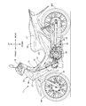
- FIG. 1 is a side view schematically showing the appearance of a saddle-ride type vehicle, that is, a motorcycle according to an embodiment of the present invention.
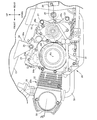
- FIG. 2 is an enlarged side view of the internal combustion engine.
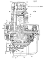
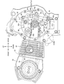
- FIG. 3 is an enlarged cross-sectional view of the internal combustion engine observed in a cross section including the cylinder axis, the rotation axis of the crankshaft, and the axes of the main shaft and the counter shaft.
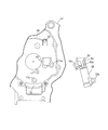
- FIG. 4 is an enlarged view of the valve operating mechanism observed in a cross section orthogonal to the crankshaft.
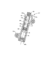
- FIG. 5 is an enlarged sectional view of the tensioner lifter.
- FIG. 1 is a side view schematically showing the appearance of a saddle-ride type vehicle, that is, a motorcycle according to an embodiment of the present invention.
- FIG. 2 is an enlarged side view of the internal combustion engine.
- FIG. 3 is an enlarged cross-sectional view of the internal combustion engine observed in a cross section including the cylinder axis, the rotation
- FIG. 6 is an enlarged exploded view schematically showing the mating surface of the first case half and the tensioner lifter.
- FIG. 7 is a side view of the second case half, schematically showing the mating surface of the second case half.
- FIG. 8 corresponds to FIG. 4 and is an enlarged view of the valve operating mechanism showing the rib below the oil supply port.
- front, rear, up, down, left, and right directions refer to directions as viewed from an occupant riding a motorcycle.
- FIG. 1 schematically shows a motorcycle according to an embodiment of the saddle type vehicle.
- the motorcycle 11 includes a body frame 12 and a body cover 13 mounted on the body frame 12.
- the body frame 12 includes a head pipe 14, a main frame 15 extending rearward and downward from the head pipe 14, a pivot frame 16 connected to a rear portion of the main frame 15 and extending downward, and a rear end connected to the main frame 15 at a front end. And a seat frame 17 extending upward.
- a front fork 18 for supporting the front wheel WF rotatably about the axle and a rod-shaped steering handle 19 are steerably supported. The driver grasps the left and right grips of the steering handle 19 when driving the motorcycle 11.
- the vehicle body cover 13 includes a front cover 21 that covers the head pipe 14 from the front, a leg shield 22 that continuously extends downward from the front cover 21, and a main cover 23 that covers the main frame 15 and the seat frame 17.
- An occupant seat 24 is mounted on the main cover 23 above the seat frame 17. The occupant straddles the occupant seat 24 when driving the motorcycle 11.
- the leg shield 22 covers the occupant's knee from the front.
- a swing arm 26 is connected to the body frame 12 behind the vehicle so as to swing up and down around a pivot 25.
- a rear wheel WR is supported at the rear end of the swing arm 26 so as to be rotatable around an axle.
- a rear cushion unit 27 is arranged between the seat frame 17 and the swing arm 26 at a position away from the pivot 25. The rear cushion unit 27 reduces vibration transmitted from the rear wheel WR to the vehicle body frame 12 when the rear wheel WR moves up and down following the ground.
- An internal combustion engine 28 that generates a driving force transmitted to the rear wheels WR is mounted on the body frame 12 between the front wheels WF and the rear wheels WR. As shown in FIG. 2, the internal combustion engine 28 includes an engine body 28a that supports accessories such as a starter motor 29. The power of the internal combustion engine 28 is transmitted to the rear wheels WR via the transmission.
- the engine body 28a includes a crankcase 31 that supports a crankshaft that generates power around the rotation axis Rx, a cylinder block 32 connected to the crankcase 31, and a cylinder head 33 connected to the cylinder block 32.
- a first engine hanger 36 a connected to a bracket 34 fixed to the main frame 15 with a bolt 35 is provided on the crankcase 31, and a first engine hanger 36 a is disposed vertically along the rear end of the crankcase 31 and is attached to the pivot frame 16 with a bolt 37.
- a second engine hanger 36b and a third engine hanger 36c to be connected are formed.
- Each bolt 35, 37 has an axis extending parallel to the rotation axis Rx.
- An intake device 38 and an exhaust device 39 are connected to the cylinder head 33.
- the intake device 38 sprays fuel from the fuel injection valve to air that is purified by the air cleaner to generate a mixture, and supplies the mixture to the engine main body 28a.
- the exhaust device 39 guides exhaust gas to the rear from the engine body 28a, purifies the exhaust gas, and exhausts the exhaust gas from the rear of the vehicle while silencing the exhaust gas.
- crankcase 31 is connected to each other at mating surfaces 42a, 43a orthogonal to the rotation axis Rx of the crankshaft 41, and defines a first crank chamber Cr that accommodates the crankshaft crank.
- the generator chamber is connected between the case half 42 and the second case half 43 and the first case half 42 by a mating surface orthogonal to the rotation axis Rx of the crankshaft.
- a left cover 44 for partitioning and a right cover 45 coupled to the second case half 43 at a mating surface orthogonal to the rotation axis Rx of the crankshaft to partition the clutch chamber between the left cover 44 and the second case half 43.
- the first case half 42, the second case half 43, and the right cover 45 are long bolts that are inserted from the first case half 42, pass through the second case half 43, and are screwed into the right cover 45. They are joined together.
- the first engine hanger 36a, the second engine hanger 36b, and the third engine hanger 36c include a first case half 42 and a second case half 43, and bolts are provided for the first case half 42 and the second case half 43. Penetrate through.
- a cylinder bore 47 is defined in the cylinder block 32.
- a piston 48 is slidably fitted in the cylinder bore 47 along the cylinder axis C (the central axis of the cylinder bore).
- the cylinder axis C inclines slightly upward.
- the cylinder block 32 guides the linear reciprocating movement of the piston 48.
- a combustion chamber 49 is defined in the cylinder head 48.
- the piston 48 faces the cylinder head 32 and partitions a combustion chamber 49 between the piston 48 and the cylinder head 32.
- An air-fuel mixture is introduced into the combustion chamber 49 from the intake device 38 in accordance with the opening / closing operation of the intake valve.
- Exhaust gas in the combustion chamber 49 is discharged through an exhaust device 39 in accordance with an opening and closing operation of an exhaust valve.
- the crankshaft 41 includes a first crank web 41a which is journaled to a bearing 52a incorporated in the first case half 42, and a second crank web 41 journally connected to a bearing 52b incorporated in the second case half 43. 41b, and a crank pin 53 extending parallel to the rotation axis Rx and connecting the first crank web 41a and the second crank web 41b to each other.
- the crank pin 53 forms a crank between the bearings 52a and 52b in cooperation with the first crank web 41a and the second crank web 41b.
- the crank is housed in the crank chamber Cr.
- a large end of a connecting rod 54 extending from the piston 48 is rotatably connected to the crank pin 53.
- the connecting rod 54 converts a linear reciprocating motion of the piston 48 into a rotary motion of the crankshaft 41.
- a valve operating mechanism 55 for transmitting the power of the crankshaft 41 to the intake valve and the exhaust valve outside the bearing 52a is connected to the crankshaft 41.
- the valve mechanism 55 includes a camshaft 56 rotatably supported by the cylinder head 33 around an axis parallel to the rotation axis Rx of the crankshaft 41, a driving sprocket 57 coaxially fixed to the crankshaft 41, The driven sprocket 58 is coaxially fixed to the shaft 56, and is wound around the driving sprocket 57 and the driven sprocket 58, moves along an annular path, and transmits the rotational force of the crankshaft 41 from the driving sprocket 57 to the driven sprocket 58.
- a timing chain (transmission member) 59 When the crankshaft 41 rotates, the camshaft 56 rotates at the determined reduction ratio, and the opening and closing operations of the intake valve and the exhaust valve are controlled.
- An AC generator (ACG) 61 that generates electric power in accordance with the rotation of the crankshaft 41 is coupled to the crankshaft 41 outside the bearing 52a.
- the ACG 61 includes an outer rotor 62 fixed to the crankshaft 41 that penetrates through the first case half 42 of the crankcase 31 and protrudes from the first case half 42, and is disposed around the crankshaft 41 surrounded by the outer rotor 62.
- an inner stator 63 is fixed to the left cover 44.
- An electromagnetic coil 63a is wound around the inner stator 63.
- a magnet 62a is fixed to the outer rotor 62. When the outer rotor 62 rotates relative to the inner stator 63, electric power is generated by the electromagnetic coil 63a.
- a starter gear 64 is fixed to the crankshaft 41 between the outer rotor 62 of the ACG 61 and the bearing 52a.
- the starter gear 64 has teeth 64 a that are annularly arranged coaxially with the rotation axis Rx of the crankshaft 41. As shown in FIG. 2, the rotational power generated by the drive shaft 29a of the starter motor 29 is transmitted to the starter gear 64 via the intermediate gear 64a. Thus, the rotation of the crankshaft 41 is caused when the internal combustion engine 28 is started.
- An oil passage 41z is formed in the second crank web 41b of the crankshaft 41, extending from the tip end along the rotation axis Rx (axial center) and connected to the ejection passage 53a in the crankpin 53.
- the engine oil is introduced from the right cover 45 to the tip of the crankshaft 41, and is supplied to the contact area between the crankpin 53 and the connecting rod 54 via the oil passage 41z.
- the valve mechanism 55 is supported by the cylinder block 32 so as to be rotatable around a rotation axis parallel to the rotation axis Rx of the crankshaft 41, and between the drive sprocket 57 and the driven sprocket 58.
- the idler 65 inscribed in the timing chain 59 and the idler 65 and the drive sprocket 57 are displaceably circumscribed on the timing chain 59 along a virtual plane orthogonal to the rotation axis Rx of the crankshaft 41 between the idler 65 and the drive sprocket 57.
- a tensioner 66 that adjusts the tension and a tensioner lifter 67 that is separably attached to the first case half 42 and applies a load to the tensioner 66 along a virtual plane orthogonal to the rotation axis Rx are incorporated.
- the tensioner 66 is supported by the first case half 42 so as to be swingable about a swing axis Sx parallel to the rotation axis Rx of the crankshaft 41, and has an arm member 66a extending forward and backward from the swing axis Sx; A tension roller 66b rotatably supported at the front end of the member 66a around a rotation axis parallel to the swing axis Sx and displaceably contacts the timing chain 59 along a virtual plane orthogonal to the rotation axis Rx of the crankshaft 41. And At the rear end of the arm member 66a, an action point 66c at which the load of the tensioner lifter 67 acts from the tangential direction around the swing axis Sx is formed. The load of the tensioner lifter 67 acts on the tension roller 66b through the swing of the arm member 66a. The tension of the timing chain 59 is adjusted according to the load of the tensioner lifter 67.
- the tensioner lifter 67 includes a casing 68 fixed to the first case half 42 and having an open end 68a that opens upward and a closed end 68b that is lower.
- the casing 68 includes a tubular portion 68t that partitions the cylinder 69 between the open end 68a and the closed end 68b.
- two mounting pieces 72a, 72b are integrally formed corresponding to the two bosses 71a, 71b formed on the outward wall surface of the first case half 42.
- Female screws having a central axis parallel to the rotation axis Rx of the crankshaft 41 are formed in each of the bosses 71a and 71b.
- the bosses 71a, 71b receive the mounting pieces 72a, 72b of the casing 68 on a receiving surface orthogonal to the rotation axis Rx of the crankshaft 41.
- the individual mounting pieces 72a, 72b are overlapped on the receiving surfaces of the corresponding bosses 71a, 71b, and fastened to the bosses 71a, 71b with bolts 73a, 73b.
- a recess 74 for accommodating the tensioner lifter 67 is provided on the inner wall surface of the first case half 42.
- the recess 74 is formed in the first case half 42 and is recessed downward in the direction of gravity on the inner wall surface of the surrounding wall 75 surrounding the outer rotor 62 and the starter gear 64 of the ACG 61 around the rotation axis Rx.
- the rear end of the tensioner lifter 67 is inserted into the recess 74 at a predetermined depth.
- the tensioner lifter 67 is axially displaceably inserted into the cylinder 69 to form an oil chamber 76 in the cylindrical portion 68t between the cylinder 69 and the closed end 68a.
- a push rod 78 having an oil path 77 that contacts the tensioner 66 at an upper end protruding from the oil chamber 68a and that communicates with the oil chamber 76 from the open end 68a.
- a check valve 79 for preventing outflow of the fluid, and a tensioner spring 81 which is disposed between the push rod 78 and the closed end 68b and exerts an elastic force for driving the push rod 78 toward the open end 68a.
- the oil path 77 extends along the axis of the push rod 78, and penetrates the axis path 77a that is opened to the oil chamber 76 at the lower end of the push rod 78 and the cylinder wall of the push rod 78 in the centrifugal direction from the axis path 77a. And a flow opening 77b that opens on the outer peripheral surface of the push rod 78.
- the check valve 79 is provided in the oil chamber 76 and has a spherical valve body which is arranged so as to be seated on a valve seat formed at the lower end of the axial path 77a.
- an enlarged diameter portion 82 which is enlarged in diameter than the cylindrical portion 68t is formed.
- the enlarged diameter portion 82 forms a space expanded around the push rod 78.
- a U-shaped wall 83 having a mating surface 83a partitioned by a plane orthogonal to the axis of the bolt 73a and defining a space that is open upward is formed in the enlarged diameter portion 82.
- a cutout 84 that exposes the outer peripheral surface of the push rod 78 is formed in the space inside the U-shaped wall 83 in the cylindrical portion 68t of the casing 68.
- a U-shaped wall 85 is formed on the outward wall surface of the first case half 42 so as to protrude from the wall surface and define a space that is open upward continuously to the space inside the enlarged diameter portion 82.
- the U-shaped wall 85 defines a plane that overlaps the mating surface 83 a of the U-shaped wall 83 of the enlarged diameter portion 82.
- the space inside the U-shaped wall 83 and the space inside the U-shaped wall 85 are continuous.
- the crankcase 31 has a wall 87 that forms the upper wall of the crankcase 31 below the starter motor 29.
- the wall body 87 includes an inner wall 87a that is in contact with the crankcase Cr, and an outer wall 87b that is arranged outside the inner wall 87a and away from the inner wall 87a and is in contact with the outside air.
- a breather chamber 88 is defined between the inner wall 87a and the outer wall 87b behind the starter motor 29.
- the breather chamber 88 is connected to the crank chamber Cr by a small hole 88a formed by combining grooves formed in mating surfaces 42a, 43a of the first case half 42 and the second case half 43.
- a nipple 88b is formed on the outer wall 87b at the upper end of the breather chamber 88 to define an outflow port connected to a breather tube connected to an air cleaner.
- a labyrinth structure is established from the small hole 88a toward the outflow port of the nipple 88b.
- the outer wall 87b is continuous with the first engine hanger 36a.
- the oil supply passage extending from the mating surface 31a with the cylinder block 32 around the rotation axis Rx of the crankshaft 41 along the mating surfaces 42a, 43a of the first case half 42 and the second case half 43 on the inner wall 87a. 89 are formed.
- the oil supply passage 89 includes a passage 89a formed by combining grooves formed in mating surfaces 42a, 43a of the first case half 42 and the second case half 43, respectively.
- the front end of the passage 89a is formed in the second case half 43 in the vertical direction from the mating surface 43a, and is connected to a front-rear passage 89b drilled from the mating surface 31a of the cylinder block 32 and the crankcase 31. Connected to.
- the front-rear passage 89b is connected to an oil pump (not shown) through a passage 91a extending along the mating surface 31a of the cylinder block 32 and the crankcase 31, and a passage formed in the second case half 43 and communicating with an oil filter. ).
- a branch passage formed in the right case 44 and connected to the oil passage 73 in the crankshaft 41 is connected to the passage 91a.
- the rear end of the oil supply passage 89 penetrates through the first case half 42 and opens toward the outside of the first case half 42 above the U-shaped wall 85 as shown in FIG. Connected to port 92.
- Engine oil is supplied to the valve mechanism 55 from the oil supply passage 89.
- a bolt 95 is screwed into the side surface of the casing 68 as shown in FIG.
- the bolt 95 may have, for example, an axis parallel to the axes of the bolts 73a and 73b.
- the bolt 95 penetrates the wall of the cylindrical portion 68t and closes a bolt hole communicating with the oil chamber 76.
- Engine oil can be injected into the oil chamber 76 from the bolt hole. After the injection of the engine oil, the bolt holes are closed with bolts 95, and the tensioner lifter 67 is assembled to the crankcase 31.
- the initial oil can be quickly stored in the oil chamber 76 during the initial operation of the internal combustion engine 28.
- a recess 74 is disposed on the inner wall surface of the engine body 28a (the first case half 42) so as to overlap with a part of the tensioner lifter 67 when viewed in the axial direction of the crankshaft 41. Therefore, the length of the tensioner lifter 67 can be ensured without shifting the position of the wall of the crankcase 31. Even when the tensioner lifter 67 is long, the tensioner lifter 67 is properly accommodated in the engine main body 28a. Enlargement of the engine body 28a is avoided. In addition, since the tensioner lifter 67 is detachably attached to the engine main body 28a, the tensioner lifter 67 can be easily replaced.
- a large-diameter portion 82 that opens upward while being larger in diameter than the cylindrical portion 68t is formed above the cylindrical portion 68t.
- the engine body 28a has a wall surface that supports the tensioner lifter 67 and has an oil supply port 92 that opens above the enlarged diameter portion 82. Therefore, the engine oil is sufficiently supplied from the oil supply port 92 to the tensioner lifter 67.
- U A U-shaped wall 85 is formed on the wall surface of the engine main body 28 a and projects from the wall surface and defines a space that is open upward continuously to the space inside the enlarged diameter portion 82. According to such a configuration, the engine oil flows around the push rod 78 more effectively.
- the tensioner lifter 67 is assembled in advance in assembling the engine body 28a.
- a push rod 78 is incorporated into the casing 68 from the open end 68a of the casing 68.
- a check valve 79 is attached to the push rod 78 in advance.
- the tensioner spring 81 Prior to the closing of the closed end 68b, the tensioner spring 81 is incorporated into the oil chamber 76 from the closed end 68b of the casing 68.
- the tensioner lifter 67 thus assembled is fastened to the first case half 42 of the crankcase 31 with bolts 73a, 73b, 73c. Since the tensioner lifter 67 is assembled in advance in a small manner, the work of assembling the engine main body 28a is made more efficient.
- a rib 93 may be formed below the oil supply port 92 on the inner wall surface of the first case half 42.
- the rib 93 protrudes from the inner wall surface of the first case half 42 in the axial direction of the crankshaft 41, and spreads from above the open end 68 a of the casing 68 toward the crankshaft 41 downward and forward. Therefore, the engine oil flowing out from the oil supply port 92 is supplied not only to the tensioner lifter 67 but also to the crankshaft 41 via the rib 93 as described above. Since the rib 93 is located forward of a vertical imaginary plane 94 including the central axis of the oil supply port 92, the tensioner lifter 67 is sufficiently supplied with engine oil.
- the rib 93 is formed in a curved shape that is displaced upward as going forward. Therefore, the engine oil can flow down from the rib 93 toward the front.
- an encircling rib 95 that is open downward and surrounds the oil supply port 92 is formed.
- the surrounding rib 95 guides engine oil flowing out of the oil supply port 92 downward. Therefore, the engine oil flowing out from the oil supply port 92 is efficiently guided to the tensioner lifter 67 and the rib 93.
Abstract
Description
28a…機関本体
41…クランクシャフト
56…カムシャフト
59…伝達部品(タイミングチェーン)
66…テンショナー
67…テンショナーリフター
68b…閉塞端
68t…筒状部
69…シリンダー
74…窪み部
76…オイル室
77…オイル路
78…プッシュロッド
82…拡径部
85…U字壁
93…リブ
95…囲みリブ 28
66
Claims (9)
- 相互に平行な回転軸線を有するクランクシャフト(41)およびカムシャフト(56)を支持する機関本体(28a)と、
前記クランクシャフト(41)および前記カムシャフト(56)に連結されて、環状経路に沿って移動し前記クランクシャフト(41)から前記カムシャフト(56)に回転力を伝達する伝達部品(59)と、
前記回転軸線(Rx)に直交する仮想平面に沿って変位自在に前記伝達部品(59)に接触して、前記伝達部品(59)の張力を調整するテンショナー(66)と、
前記機関本体(28a)に取り付けられて、前記仮想平面に沿って前記テンショナー(66)に荷重を付与するテンショナーリフター(67)と
を備える内燃機関において、
前記機関本体(28a)の内壁面には、クランクシャフト(41)の軸方向視で、前記テンショナーリフター(67)の一部と重なるように配置される窪み部(74)が配置される
ことを特徴とする内燃機関。 An engine body (28a) supporting a crankshaft (41) and a camshaft (56) having mutually parallel axes of rotation;
A transmission component (59) connected to the crankshaft (41) and the camshaft (56), moving along an annular path, and transmitting rotational force from the crankshaft (41) to the camshaft (56); ,
A tensioner (66) that contacts the transmission component (59) to be displaceable along an imaginary plane orthogonal to the rotation axis (Rx) and adjusts the tension of the transmission component (59);
A tensioner lifter (67) attached to the engine body (28a) and applying a load to the tensioner (66) along the virtual plane;
A depression (74) is disposed on the inner wall surface of the engine body (28a) so as to overlap a part of the tensioner lifter (67) when viewed in the axial direction of the crankshaft (41). Features internal combustion engine. - 請求項1に記載の内燃機関において、前記テンショナーリフター(67)は、
前記機関本体(28a)に固定されてシリンダー(69)を区画する筒状部(68t)と、
前記シリンダー(69)に軸方向に変位自在に挿入されて、筒状部の閉塞端(68b)との間で前記筒状部内にオイル室(76)を形成し、前記筒状部から突出する上端で前記テンショナー(66)に接触し前記テンショナー(66)に張力を与え、前記筒状部(68t)の上端から前記オイル室(76)に通じるオイル路(77)を有するプッシュロッド(78)と、
前記筒状部(68t)の上方に配置され、前記筒状部(68t)よりも拡径されつつ上向きに開口する拡径部(82)と
を備えることを特徴とする内燃機関。 The internal combustion engine according to claim 1, wherein the tensioner lifter (67) comprises:
A tubular portion (68t) fixed to the engine body (28a) and defining a cylinder (69);
The cylinder (69) is axially displaceably inserted into the cylinder (69) to form an oil chamber (76) in the cylinder with the closed end (68b) of the cylinder, and protrudes from the cylinder. A push rod (78) having an oil path (77) leading from the upper end of the tubular portion (68t) to the oil chamber (76) by contacting the tensioner (66) at its upper end to apply tension to the tensioner (66). When,
An internal combustion engine, comprising: a large-diameter portion (82) disposed above the cylindrical portion (68t) and opening upward while having a larger diameter than the cylindrical portion (68t). - 請求項2に記載の内燃機関において、前記機関本体(28a)には、前記テンショナーリフター(67)を支持し、前記拡径部(82)の上方で開口するオイル供給口(92)を有する壁面が形成されることを特徴とする内燃機関。 3. The internal combustion engine according to claim 2, wherein the engine body (28a) supports the tensioner lifter (67) and has an oil supply port (92) that opens above the enlarged diameter portion (82). Is formed.
- 請求項3に記載の内燃機関において、前記拡径部(82)は前記機関本体(28a)の壁に向かって開口し前記機関本体(28a)の壁に結合されることを特徴とする内燃機関。 The internal combustion engine according to claim 3, wherein the enlarged diameter portion (82) opens toward a wall of the engine body (28a) and is connected to a wall of the engine body (28a). .
- 請求項4に記載の内燃機関において、前記壁面には、前記壁面から突出して、前記拡径部(82)内の空間に連続して上向きに開放される空間を区画するU字壁(85)が形成されることを特徴とする内燃機関。 5. The internal combustion engine according to claim 4, wherein the wall has a U-shaped wall protruding from the wall and defining a space that is open upward continuously to a space in the enlarged diameter portion. Is formed.
- 請求項3~5のいずれか1項に記載の内燃機関において、前記壁面には、前記オイル供給口(92)の下方で前記壁面から突出するリブ(93)が形成されることを特徴とする内燃機関。 The internal combustion engine according to any one of claims 3 to 5, wherein a rib (93) protruding from the wall surface below the oil supply port (92) is formed on the wall surface. Internal combustion engine.
- 請求項6に記載の内燃機関において、前記リブ(93)は、前記拡径部(82)の上方から前下がりに前記クランクシャフト(41)に向かって延びることを特徴とする内燃機関。 The internal combustion engine according to claim 6, wherein the rib (93) extends forward from above the enlarged diameter portion (82) toward the crankshaft (41).
- 請求項7に記載の内燃機関において、前記リブ(93)は、前方にいくにつれて上方に変位する湾曲形状に形成されることを特徴とする内燃機関。 The internal combustion engine according to claim 7, wherein the rib (93) is formed in a curved shape that is displaced upward as going forward.
- 請求項6~9のいずれか1項に記載の内燃機関において、前記壁面には、前記オイル供給口(92)を囲んで下向きに開放される囲みリブ(95)が形成されることを特徴とする内燃機関。
The internal combustion engine according to any one of claims 6 to 9, wherein an encircling rib (95) is formed on the wall surface and is opened downward around the oil supply port (92). Internal combustion engine.
Priority Applications (4)
| Application Number | Priority Date | Filing Date | Title |
|---|---|---|---|
| JP2020546224A JP7009644B2 (en) | 2018-09-14 | 2019-09-13 | Internal combustion engine |
| BR112021003604-0A BR112021003604A2 (en) | 2018-09-14 | 2019-09-13 | internal combustion engine |
| CN201990001021.1U CN214944564U (en) | 2018-09-14 | 2019-09-13 | Internal combustion engine |
| PH12021550541A PH12021550541A1 (en) | 2018-09-14 | 2021-03-11 | Internal combustion engine |
Applications Claiming Priority (4)
| Application Number | Priority Date | Filing Date | Title |
|---|---|---|---|
| JP2018172933 | 2018-09-14 | ||
| JP2018-172933 | 2018-09-14 | ||
| JP2019-010183 | 2019-01-24 | ||
| JP2019010183 | 2019-01-24 |
Publications (1)
| Publication Number | Publication Date |
|---|---|
| WO2020054846A1 true WO2020054846A1 (en) | 2020-03-19 |
Family
ID=69777125
Family Applications (1)
| Application Number | Title | Priority Date | Filing Date |
|---|---|---|---|
| PCT/JP2019/036087 WO2020054846A1 (en) | 2018-09-14 | 2019-09-13 | Internal combustion engine |
Country Status (5)
| Country | Link |
|---|---|
| JP (1) | JP7009644B2 (en) |
| CN (1) | CN214944564U (en) |
| BR (1) | BR112021003604A2 (en) |
| PH (1) | PH12021550541A1 (en) |
| WO (1) | WO2020054846A1 (en) |
Cited By (1)
| Publication number | Priority date | Publication date | Assignee | Title |
|---|---|---|---|---|
| JP7342083B2 (en) | 2021-09-30 | 2023-09-11 | 本田技研工業株式会社 | power unit |
Citations (7)
| Publication number | Priority date | Publication date | Assignee | Title |
|---|---|---|---|---|
| JPH0228507U (en) * | 1988-08-15 | 1990-02-23 | ||
| JPH0269001U (en) * | 1988-11-16 | 1990-05-25 | ||
| JPH0269027U (en) * | 1988-11-15 | 1990-05-25 | ||
| JPH0269005U (en) * | 1988-11-16 | 1990-05-25 | ||
| EP1522682A1 (en) * | 2003-10-09 | 2005-04-13 | Ford Global Technologies, LLC | A camshaft drive assembly and a case and a chain guide for a camshaft drive assembly |
| JP2014238008A (en) * | 2013-06-06 | 2014-12-18 | スズキ株式会社 | Attaching structure of idler pulley of engine |
| JP2016038036A (en) * | 2014-08-08 | 2016-03-22 | 日本発條株式会社 | Load application device |
Family Cites Families (1)
| Publication number | Priority date | Publication date | Assignee | Title |
|---|---|---|---|---|
| JP5381381B2 (en) * | 2009-06-19 | 2014-01-08 | 日産自動車株式会社 | Chain tensioner |
-
2019
- 2019-09-13 WO PCT/JP2019/036087 patent/WO2020054846A1/en active Application Filing
- 2019-09-13 BR BR112021003604-0A patent/BR112021003604A2/en active Search and Examination
- 2019-09-13 CN CN201990001021.1U patent/CN214944564U/en active Active
- 2019-09-13 JP JP2020546224A patent/JP7009644B2/en active Active
-
2021
- 2021-03-11 PH PH12021550541A patent/PH12021550541A1/en unknown
Patent Citations (7)
| Publication number | Priority date | Publication date | Assignee | Title |
|---|---|---|---|---|
| JPH0228507U (en) * | 1988-08-15 | 1990-02-23 | ||
| JPH0269027U (en) * | 1988-11-15 | 1990-05-25 | ||
| JPH0269001U (en) * | 1988-11-16 | 1990-05-25 | ||
| JPH0269005U (en) * | 1988-11-16 | 1990-05-25 | ||
| EP1522682A1 (en) * | 2003-10-09 | 2005-04-13 | Ford Global Technologies, LLC | A camshaft drive assembly and a case and a chain guide for a camshaft drive assembly |
| JP2014238008A (en) * | 2013-06-06 | 2014-12-18 | スズキ株式会社 | Attaching structure of idler pulley of engine |
| JP2016038036A (en) * | 2014-08-08 | 2016-03-22 | 日本発條株式会社 | Load application device |
Cited By (1)
| Publication number | Priority date | Publication date | Assignee | Title |
|---|---|---|---|---|
| JP7342083B2 (en) | 2021-09-30 | 2023-09-11 | 本田技研工業株式会社 | power unit |
Also Published As
| Publication number | Publication date |
|---|---|
| BR112021003604A2 (en) | 2021-05-18 |
| PH12021550541A1 (en) | 2022-02-14 |
| JPWO2020054846A1 (en) | 2021-09-02 |
| CN214944564U (en) | 2021-11-30 |
| JP7009644B2 (en) | 2022-01-28 |
Similar Documents
| Publication | Publication Date | Title |
|---|---|---|
| EP2853701B1 (en) | Variable valve gear of internal combustion engine | |
| WO2020054846A1 (en) | Internal combustion engine | |
| JP6484274B2 (en) | Internal combustion engine for saddle-ride type vehicles | |
| CN214741701U (en) | Internal combustion engine | |
| EP2853700B1 (en) | Variable valve gear of internal combustion engine for saddle-ride type vehicle | |
| JP2008190424A (en) | Decompression device for internal combustion engine | |
| JP4781335B2 (en) | On-vehicle power unit | |
| WO2019221225A1 (en) | Saddle type vehicle | |
| EP1378434A1 (en) | Power unit support structure in motorcycle | |
| WO2021192273A1 (en) | Internal combustion engine | |
| CN111164294B (en) | Internal combustion engine | |
| JP3547861B2 (en) | Kick starter for motorcycles | |
| JPWO2018168575A1 (en) | Belt type continuously variable transmission | |
| JP6542828B2 (en) | Internal combustion engine | |
| JP3975144B2 (en) | Power unit with 4-cycle single cylinder engine | |
| EP1378635B1 (en) | Assembly opening portion closing structure in engine | |
| JP2008190423A (en) | Oil feeding structure of ohc-type internal combustion engine | |
| JP4538279B2 (en) | Direct fuel injection internal combustion engine | |
| EP3421838B1 (en) | Electronically controlled v-belt continuously variable transmission | |
| EP3421840B1 (en) | Electronically controlled v-belt continuously variable transmission | |
| WO2017168618A1 (en) | Lubricant supply structure of internal combustion engine for vehicle | |
| JP2009079691A (en) | Power unit | |
| JP2019173611A (en) | engine | |
| JP2017150546A5 (en) | ||
| JP2005035430A (en) | Engine equipped with hydraulic clutch |
Legal Events
| Date | Code | Title | Description |
|---|---|---|---|
| 121 | Ep: the epo has been informed by wipo that ep was designated in this application |
Ref document number: 19859450 Country of ref document: EP Kind code of ref document: A1 |
|
| DPE1 | Request for preliminary examination filed after expiration of 19th month from priority date (pct application filed from 20040101) | ||
| ENP | Entry into the national phase |
Ref document number: 2020546224 Country of ref document: JP Kind code of ref document: A |
|
| WWE | Wipo information: entry into national phase |
Ref document number: 2101001293 Country of ref document: TH |
|
| REG | Reference to national code |
Ref country code: BR Ref legal event code: B01A Ref document number: 112021003604 Country of ref document: BR |
|
| NENP | Non-entry into the national phase |
Ref country code: DE |
|
| ENP | Entry into the national phase |
Ref document number: 112021003604 Country of ref document: BR Kind code of ref document: A2 Effective date: 20210225 |
|
| 122 | Ep: pct application non-entry in european phase |
Ref document number: 19859450 Country of ref document: EP Kind code of ref document: A1 |