WO2020054072A1 - Titanium foil and method for producing same - Google Patents
Titanium foil and method for producing same Download PDFInfo
- Publication number
- WO2020054072A1 WO2020054072A1 PCT/JP2018/034274 JP2018034274W WO2020054072A1 WO 2020054072 A1 WO2020054072 A1 WO 2020054072A1 JP 2018034274 W JP2018034274 W JP 2018034274W WO 2020054072 A1 WO2020054072 A1 WO 2020054072A1
- Authority
- WO
- WIPO (PCT)
- Prior art keywords
- compound
- titanium
- less
- titanium foil
- layer
- Prior art date
Links
Images


Classifications
-
- C—CHEMISTRY; METALLURGY
- C22—METALLURGY; FERROUS OR NON-FERROUS ALLOYS; TREATMENT OF ALLOYS OR NON-FERROUS METALS
- C22C—ALLOYS
- C22C14/00—Alloys based on titanium
-
- C—CHEMISTRY; METALLURGY
- C22—METALLURGY; FERROUS OR NON-FERROUS ALLOYS; TREATMENT OF ALLOYS OR NON-FERROUS METALS
- C22F—CHANGING THE PHYSICAL STRUCTURE OF NON-FERROUS METALS AND NON-FERROUS ALLOYS
- C22F1/00—Changing the physical structure of non-ferrous metals or alloys by heat treatment or by hot or cold working
- C22F1/16—Changing the physical structure of non-ferrous metals or alloys by heat treatment or by hot or cold working of other metals or alloys based thereon
- C22F1/18—High-melting or refractory metals or alloys based thereon
-
- C—CHEMISTRY; METALLURGY
- C23—COATING METALLIC MATERIAL; COATING MATERIAL WITH METALLIC MATERIAL; CHEMICAL SURFACE TREATMENT; DIFFUSION TREATMENT OF METALLIC MATERIAL; COATING BY VACUUM EVAPORATION, BY SPUTTERING, BY ION IMPLANTATION OR BY CHEMICAL VAPOUR DEPOSITION, IN GENERAL; INHIBITING CORROSION OF METALLIC MATERIAL OR INCRUSTATION IN GENERAL
- C23C—COATING METALLIC MATERIAL; COATING MATERIAL WITH METALLIC MATERIAL; SURFACE TREATMENT OF METALLIC MATERIAL BY DIFFUSION INTO THE SURFACE, BY CHEMICAL CONVERSION OR SUBSTITUTION; COATING BY VACUUM EVAPORATION, BY SPUTTERING, BY ION IMPLANTATION OR BY CHEMICAL VAPOUR DEPOSITION, IN GENERAL
- C23C28/00—Coating for obtaining at least two superposed coatings either by methods not provided for in a single one of groups C23C2/00 - C23C26/00 or by combinations of methods provided for in subclasses C23C and C25C or C25D
- C23C28/04—Coating for obtaining at least two superposed coatings either by methods not provided for in a single one of groups C23C2/00 - C23C26/00 or by combinations of methods provided for in subclasses C23C and C25C or C25D only coatings of inorganic non-metallic material
-
- C—CHEMISTRY; METALLURGY
- C23—COATING METALLIC MATERIAL; COATING MATERIAL WITH METALLIC MATERIAL; CHEMICAL SURFACE TREATMENT; DIFFUSION TREATMENT OF METALLIC MATERIAL; COATING BY VACUUM EVAPORATION, BY SPUTTERING, BY ION IMPLANTATION OR BY CHEMICAL VAPOUR DEPOSITION, IN GENERAL; INHIBITING CORROSION OF METALLIC MATERIAL OR INCRUSTATION IN GENERAL
- C23C—COATING METALLIC MATERIAL; COATING MATERIAL WITH METALLIC MATERIAL; SURFACE TREATMENT OF METALLIC MATERIAL BY DIFFUSION INTO THE SURFACE, BY CHEMICAL CONVERSION OR SUBSTITUTION; COATING BY VACUUM EVAPORATION, BY SPUTTERING, BY ION IMPLANTATION OR BY CHEMICAL VAPOUR DEPOSITION, IN GENERAL
- C23C8/00—Solid state diffusion of only non-metal elements into metallic material surfaces; Chemical surface treatment of metallic material by reaction of the surface with a reactive gas, leaving reaction products of surface material in the coating, e.g. conversion coatings, passivation of metals
- C23C8/06—Solid state diffusion of only non-metal elements into metallic material surfaces; Chemical surface treatment of metallic material by reaction of the surface with a reactive gas, leaving reaction products of surface material in the coating, e.g. conversion coatings, passivation of metals using gases
- C23C8/08—Solid state diffusion of only non-metal elements into metallic material surfaces; Chemical surface treatment of metallic material by reaction of the surface with a reactive gas, leaving reaction products of surface material in the coating, e.g. conversion coatings, passivation of metals using gases only one element being applied
- C23C8/24—Nitriding
-
- H—ELECTRICITY
- H01—ELECTRIC ELEMENTS
- H01M—PROCESSES OR MEANS, e.g. BATTERIES, FOR THE DIRECT CONVERSION OF CHEMICAL ENERGY INTO ELECTRICAL ENERGY
- H01M8/00—Fuel cells; Manufacture thereof
- H01M8/02—Details
- H01M8/0202—Collectors; Separators, e.g. bipolar separators; Interconnectors
- H01M8/0204—Non-porous and characterised by the material
- H01M8/0206—Metals or alloys
- H01M8/0208—Alloys
-
- H—ELECTRICITY
- H01—ELECTRIC ELEMENTS
- H01M—PROCESSES OR MEANS, e.g. BATTERIES, FOR THE DIRECT CONVERSION OF CHEMICAL ENERGY INTO ELECTRICAL ENERGY
- H01M8/00—Fuel cells; Manufacture thereof
- H01M8/02—Details
- H01M8/0202—Collectors; Separators, e.g. bipolar separators; Interconnectors
- H01M8/0204—Non-porous and characterised by the material
- H01M8/0215—Glass; Ceramic materials
-
- H—ELECTRICITY
- H01—ELECTRIC ELEMENTS
- H01M—PROCESSES OR MEANS, e.g. BATTERIES, FOR THE DIRECT CONVERSION OF CHEMICAL ENERGY INTO ELECTRICAL ENERGY
- H01M8/00—Fuel cells; Manufacture thereof
- H01M8/02—Details
- H01M8/0202—Collectors; Separators, e.g. bipolar separators; Interconnectors
- H01M8/0204—Non-porous and characterised by the material
- H01M8/0223—Composites
- H01M8/0228—Composites in the form of layered or coated products
-
- H—ELECTRICITY
- H01—ELECTRIC ELEMENTS
- H01M—PROCESSES OR MEANS, e.g. BATTERIES, FOR THE DIRECT CONVERSION OF CHEMICAL ENERGY INTO ELECTRICAL ENERGY
- H01M8/00—Fuel cells; Manufacture thereof
- H01M8/10—Fuel cells with solid electrolytes
-
- C—CHEMISTRY; METALLURGY
- C22—METALLURGY; FERROUS OR NON-FERROUS ALLOYS; TREATMENT OF ALLOYS OR NON-FERROUS METALS
- C22F—CHANGING THE PHYSICAL STRUCTURE OF NON-FERROUS METALS AND NON-FERROUS ALLOYS
- C22F1/00—Changing the physical structure of non-ferrous metals or alloys by heat treatment or by hot or cold working
-
- C—CHEMISTRY; METALLURGY
- C23—COATING METALLIC MATERIAL; COATING MATERIAL WITH METALLIC MATERIAL; CHEMICAL SURFACE TREATMENT; DIFFUSION TREATMENT OF METALLIC MATERIAL; COATING BY VACUUM EVAPORATION, BY SPUTTERING, BY ION IMPLANTATION OR BY CHEMICAL VAPOUR DEPOSITION, IN GENERAL; INHIBITING CORROSION OF METALLIC MATERIAL OR INCRUSTATION IN GENERAL
- C23C—COATING METALLIC MATERIAL; COATING MATERIAL WITH METALLIC MATERIAL; SURFACE TREATMENT OF METALLIC MATERIAL BY DIFFUSION INTO THE SURFACE, BY CHEMICAL CONVERSION OR SUBSTITUTION; COATING BY VACUUM EVAPORATION, BY SPUTTERING, BY ION IMPLANTATION OR BY CHEMICAL VAPOUR DEPOSITION, IN GENERAL
- C23C22/00—Chemical surface treatment of metallic material by reaction of the surface with a reactive liquid, leaving reaction products of surface material in the coating, e.g. conversion coatings, passivation of metals
- C23C22/05—Chemical surface treatment of metallic material by reaction of the surface with a reactive liquid, leaving reaction products of surface material in the coating, e.g. conversion coatings, passivation of metals using aqueous solutions
- C23C22/06—Chemical surface treatment of metallic material by reaction of the surface with a reactive liquid, leaving reaction products of surface material in the coating, e.g. conversion coatings, passivation of metals using aqueous solutions using aqueous acidic solutions with pH less than 6
-
- Y—GENERAL TAGGING OF NEW TECHNOLOGICAL DEVELOPMENTS; GENERAL TAGGING OF CROSS-SECTIONAL TECHNOLOGIES SPANNING OVER SEVERAL SECTIONS OF THE IPC; TECHNICAL SUBJECTS COVERED BY FORMER USPC CROSS-REFERENCE ART COLLECTIONS [XRACs] AND DIGESTS
- Y02—TECHNOLOGIES OR APPLICATIONS FOR MITIGATION OR ADAPTATION AGAINST CLIMATE CHANGE
- Y02E—REDUCTION OF GREENHOUSE GAS [GHG] EMISSIONS, RELATED TO ENERGY GENERATION, TRANSMISSION OR DISTRIBUTION
- Y02E60/00—Enabling technologies; Technologies with a potential or indirect contribution to GHG emissions mitigation
- Y02E60/30—Hydrogen technology
- Y02E60/50—Fuel cells
-
- Y—GENERAL TAGGING OF NEW TECHNOLOGICAL DEVELOPMENTS; GENERAL TAGGING OF CROSS-SECTIONAL TECHNOLOGIES SPANNING OVER SEVERAL SECTIONS OF THE IPC; TECHNICAL SUBJECTS COVERED BY FORMER USPC CROSS-REFERENCE ART COLLECTIONS [XRACs] AND DIGESTS
- Y02—TECHNOLOGIES OR APPLICATIONS FOR MITIGATION OR ADAPTATION AGAINST CLIMATE CHANGE
- Y02P—CLIMATE CHANGE MITIGATION TECHNOLOGIES IN THE PRODUCTION OR PROCESSING OF GOODS
- Y02P70/00—Climate change mitigation technologies in the production process for final industrial or consumer products
- Y02P70/50—Manufacturing or production processes characterised by the final manufactured product
Definitions
- the present invention relates to a titanium foil and a method for producing the same.
- Fuel cells are being developed as driving power sources for vehicles and stationary power generation devices, against the background of recent energy problems and environmental problems such as global warming.
- a polymer electrolyte fuel cell that can operate at a low temperature of 100 ° C. or less has attracted attention, and its development and commercialization have been promoted.
- This polymer electrolyte fuel cell generally has a membrane electrode assembly (MEA: Membrane Electrode Assembly) in which a catalyst layer serving as an anode and a catalyst layer serving as a cathode are arranged with a proton-conductive electrolyte membrane interposed therebetween.
- a gas diffusion layer made of carbon is disposed outside the membrane electrode assembly, and a separator is disposed outside the gas diffusion layer.
- This basic structure is called a unit cell.
- a fuel cell is usually configured by stacking a required number of unit cells to achieve a required output.
- an oxidizing gas such as oxygen or air is supplied to a cathode side from gas flow paths of separators provided on an anode side and a cathode side, respectively.
- a fuel gas such as hydrogen is supplied to the anode side.
- the oxidizing gas and the fuel gas are supplied to the catalyst layer via the gas diffusion layer, respectively, and an energy difference (potential difference) between an electrochemical reaction occurring in the anode catalyst layer and an electrochemical reaction occurring in the cathode catalyst layer is performed.
- an energy difference potential difference between an electrochemical reaction occurring in the anode catalyst layer and an electrochemical reaction occurring in the cathode catalyst layer is performed.
- hydrogen gas is used as fuel gas
- oxygen gas is used as oxidizing gas.
- the potential of the separator becomes equal to the potential of the catalyst layer, and particularly at the cathode, the potential is maintained at a high potential of about 1 V even if the overvoltage generated due to various causes is subtracted, and the operating temperature of the fuel cell becomes 60 to 90 ° C. Since the temperature is maintained, the separator is used under a strong oxidizing condition.
- the polymer electrolyte fuel cell is operated under a strongly acidic condition having a pH of 4 or less and under an environment in which fluorine derived from the electrolyte membrane and halogen ions such as chloride ions taken in from the atmosphere coexist.
- fluorine derived from the electrolyte membrane and halogen ions such as chloride ions taken in from the atmosphere coexist.
- a so-called non-conductive coating it is essential to form a highly corrosion-resistant coating on the metal surface of the separator, a so-called non-conductive coating.
- the non-conductive film formed on the metal surface is usually formed as an oxide of a metal component, that is, a metal oxide as a main component.
- metal oxides are often non-conductors, and special measures are required to develop the conductivity required for the separator.
- Patent Document 1 an invention using a special stainless steel in which a conductive compound is precipitated in a steel material (Patent Document 1) and an invention using a titanium-based material in which TiB-based precipitates are dispersed in titanium (Patent Document 2) ), And many other inventions have been proposed so far.
- Patent Document 3 on a titanium or titanium alloy substrate (titanium substrate layer), any of tantalum, titanium, vanadium, zirconium or chromium carbide, nitride, carbonitride and boride is used. It has an oxide film (conductive surface layer) in which a conductive material having a major axis diameter of 1 nm or more and 100 nm or less is dispersed, and is immersed in an aqueous sulfuric acid solution at pH 4 at 80 ° C. for 4 days.
- oxide film conductive surface layer
- a titanium base layer and a surface layer are formed, the titanium base layer has a recrystallized structure, and the surface layer is formed of Ti in which O, C, and N are dissolved.
- O, C, and N only a compound-containing titanium layer (conductive surface layer) having a thickness of less than 1 ⁇ m in which a compound formed by Ti and Ti is mixed, or the compound-containing titanium layer; It consists of a passivation film (conductive surface layer composed of a compound-containing titanium layer and a passivation film) having a thickness of less than 5 nm formed on its surface, the passivation film is appropriately destroyed, and its regeneration is suppressed.
- a titanium plate material for a fuel cell separator titanium foil for a separator
- a method for producing the same have been proposed that can reliably achieve a low contact resistance.
- Patent Document 5 proposes a composite metal foil for a fuel cell separator in which the surface of a titanium foil or a titanium alloy foil is coated with a predetermined conductive layer, and a method for producing the same.
- a titanium substrate made of titanium or a titanium alloy is subjected to a dipping treatment in a non-oxidizing acid or a cathodic electrolytic treatment and a subsequent heat treatment, whereby X-rays are applied to the surface of the titanium substrate.
- the present inventors first conceived of using a fuel cell under a more severe use environment than previously assumed.
- a conventional accelerated deterioration test for example, “Evaluation test of immersing in a sulfuric acid aqueous solution of pH 4 at 80 ° C.
- Patent Document 3 A new accelerated degradation test to investigate conductivity and corrosion resistance under even more severe conditions than that of "Impact test at 80 ° C for 4 days (96 hours) containing 100 ppm of fluoride ions at pH 3-sulfuric acid aqueous solution for 4 days (96 hours)" (Test for immersion in a sulfuric acid aqueous solution at a concentration of 0.005 wt% at pH 3 at 90 ° C. for 100 hours for evaluation) was set. In this new accelerated aging test, what kind of conductivity and corrosion resistance each titanium foil for a separator described in Patent Documents 3 to 5 has been examined.
- the present inventors next examined in detail the causes of the titanium foils of Patent Documents 3 to 5 not exhibiting the desired conductivity and corrosion resistance in a new accelerated deterioration test. Focused on the presence of a TiC compound in each of the conductive surface layers (the oxide film of Patent Document 3, the compound-containing titanium layer of Patent Document 4, and the oxide film of Patent Document 5).
- the TiC compound dissolves relatively easily in the new accelerated aging test described above and is passivated in the conductive surface layer to form the non-conductive passive material TiO 2 or by dissolution of the TiC compound. It has been found that the oxidation of pure titanium in the metal proceeds, and as a result, the conductivity of the conductive surface layer is reduced or the suppression of corrosion is impaired.
- the reason why the TiC compound is mixed in the conductive surface layer is not necessarily clear, but the titanium plate material made of titanium or a titanium alloy used as a raw material is originally solid. It is considered that dissolved carbon and carbon derived from the rolling oil used during cold rolling of the titanium sheet material are considered to be carbon sources. The solid solution carbon and the carbon derived from the rolling oil in these titanium sheet materials are chemically bonded to Ti on the surface of the titanium sheet material during cold rolling and / or bright annealing treatment to form a TiC compound. It is considered something.
- this TiC compound is inevitably generated on the surface of the titanium sheet material by bright annealing after cold rolling, and therefore, as long as the cold rolling and bright annealing are performed in the manufacturing process, the TiC compound is produced. It is considered that the generation of the TiC compound is inevitable even if the rolling oil is washed after the cold rolling of the sheet material.
- TiO compound> TiN compound> TiC compound are superior in the order of corrosion resistance from the viewpoint of corrosion resistance, and TiC compound> TiN compound> TiO compound from the viewpoint of conductivity. Excellent in order. Focusing on the fact that the TiN compound has sufficient conductivity for use as a separator, further studies were conducted on developing a titanium foil for a separator having excellent performance in the above-mentioned accelerated deterioration test.
- the present invention is as follows. [1] In mass%, C: 0.080% or less, H: 0.013% or less, O: 0.40% or less, N: 0.050% or less, Fe: 0.50% or less, A base material layer having a chemical composition that is a balance of Ti and impurities, With a surface layer having conductivity formed on the surface of the base material layer, The surface layer is a Ti compound including a TiN compound and a TiO compound, and not including a TiC compound. Titanium foil.
- the surface layer is measured by an X-ray diffraction method, one or both diffraction peaks of a TiN compound and a Ti 2 N compound are observed, no diffraction peaks of other compounds are observed, and the surface layer
- the XPS spectrum is measured from the side, one of the peaks of the TiO 2 compound and the peak of one or both of the TiO x compounds is observed, and other than these, the peak of Ti is not observed.
- the surface layer has a thickness of 20 nm to 500 nm; The titanium foil of the above [1] or [2].
- the surface layer provides the X-ray diffraction spectrum, the ratio between the peak P a2 of the peak P a1 and TiN compound of Ti 2 N compound (P a1 / P a2) is from 1.6 to 2.6
- the titanium foil according to any one of the above [1] to [3].
- the conductive surface layer has a ratio (P b1 / P b2 ) of the peak P b1 of the TiO 2 compound to the peak P b2 of the TiO x compound in the XPS spectrum of Ti2p of 1.7 to 2.8. is there, The titanium foil according to any one of the above [1] to [4].
- a method for producing a titanium foil comprising: [8] After the step (2) and before the step (3), a light-volume annealing treatment is performed.
- the step (3) includes: As an acid treatment liquid, a mixed solution of sulfuric acid and hydrogen peroxide, using nitric acid or hydrogen peroxide, The method for producing a titanium foil according to the above [7] or [8].
- a titanium foil having excellent conductivity and corrosion resistance can be provided.
- the titanium foil of the present invention not only the conductivity is excellent, but also the conductivity is excellent even under the severe use environment of the fuel cell which is exposed to a higher temperature due to the increase in capacity and compactness.
- a separator of a polymer electrolyte fuel cell that can exhibit corrosion resistance can be manufactured. Further, according to the present invention, it is possible to provide a method for producing the above-mentioned titanium foil.
- FIG. 1 is a schematic diagram showing a cross-sectional structure of a titanium foil according to the present invention.
- FIG. 13 is a transmission electron microscope (TEM: Transmission Electron Microscope) image of a partial cross section of the titanium foil of No. 13, (a) shows a TEM image, (b) shows the position of each compound in the TEM image of (a). Is shown.
- FIG. 3 is a schematic diagram showing a cross-sectional structure of the annealed titanium plate material.
- FIG. 4 is a schematic diagram showing a cross-sectional structure of the first acid-treated titanium plate material.
- FIG. 5 is a schematic diagram showing a cross-sectional structure of a titanium foil obtained by performing a second acid treatment on a first acid-treated titanium plate material.
- FIG. 13 is a transmission electron microscope (TEM: Transmission Electron Microscope) image of a partial cross section of the titanium foil of No. 13, (a) shows a TEM image, (b) shows the position of each compound in the TEM image of (a
- FIG. 6 is a schematic diagram showing a cross-sectional structure of a titanium sheet material (second annealed titanium sheet material) obtained by performing the second annealing on the first acid-treated titanium sheet material.
- FIG. 7 is a schematic diagram showing a cross-sectional structure of a titanium foil obtained by performing a second acid treatment on a second annealed titanium plate material.
- the titanium foil according to the present invention is used, for example, for a separator of a polymer electrolyte fuel cell.
- the titanium foil according to the present invention includes a base layer 1 and a conductive surface layer 2 formed on the surface of the base layer 1.
- the surface layer 2 is a Ti compound containing a TiN compound 2a and a TiO compound 2b, but not containing a TiC compound.
- the titanium foil according to the present invention does not contain a TiC compound that is relatively easily dissolved in the above-mentioned new accelerated deterioration test, so that it can exhibit excellent conductivity and corrosion resistance even under a severe use environment of a fuel cell.
- the base material layer 1 is, by mass%, C: 0.080% or less, H: 0.013% or less, O: 0.40% or less, N: 0.050% or less, Fe: 0.50% or less, It has the chemical composition of the remainder Ti and impurities.
- JIS Class 1 to Class 4 are defined in JIS H4600: 2012.
- JIS Class 1 means C: 0.08% or less, H: 0.013% or less, O: 0.15% or less, N: 0.03% or less, Fe: 0.20% or less, composition of balance Ti and impurities Having.
- JIS Class 2 means C: 0.08% or less, H: 0.013% or less, O: 0.20% or less, N: 0.03% or less, Fe: 0.25% or less, balance of Ti and impurities. Having a composition.
- JIS Class 3 means C: 0.08% or less, H: 0.014% or less, O: 0.30% or less, N: 0.05% or less, Fe: 0.30% or less, balance of Ti and impurities Having a composition.
- JIS Class 4 means C: 0.08% or less, H: 0.013% or less, O: 0.40% or less, N: 0.05% or less, Fe: 0.50% or less, balance of Ti and impurities. Having a composition.
- the thickness of the base material layer 1 may be appropriately set according to its use, and is, for example, 0.03 mm or more and 0.1 mm or less. A preferred lower limit is 0.03 mm, and a preferred upper limit is 0.05 mm.
- the surface layer 2 is a conductive surface layer, and includes a Ti compound containing a TiN compound 2a and a TiO compound 2b and not containing a TiC compound.
- the thickness of the surface layer 2 is preferably 20 nm or more and 500 nm or less. If it is less than 20 nm, it is difficult to secure sufficient conductivity and corrosion resistance, and if it exceeds 500 nm, the conductivity may be reduced.
- the preferred lower limit of the surface layer 2 is 100 nm, and the preferred upper limit is 300 nm. As shown in FIG.
- the surface layer 2 is composed of a layer composed of a TiN compound 2a as an inner layer close to the surface of the substrate layer 1, and a TiO compound 2b as an outer layer remote from the surface of the substrate layer 1. And a layer to be formed.
- the surface layer 2 having such a configuration is used in an acid environment or a high-temperature environment, excellent corrosion resistance is exhibited by the TiO compound 2b constituting the outer layer, and the excellent conductivity of the TiN compound 2a constituting the inner layer is exhibited. Can be maintained for a long period of time. Since it is difficult to strictly define the thickness of the inner layer composed of the TiN compound 2a and the thickness of the outer layer composed of the TiO compound 2b, the thickness is evaluated by the average value of the thickness measured by the following method.
- a thin slice sample processed to a thickness (for example, about 100 nm) that can be observed with a TEM by a method such as FIB is prepared, and an image obtained by TEM observation of this sample shows that a TiN compound is randomly selected at 50 locations.
- the thicknesses of 2a and TiO compound 2b are measured, and the average value is defined as the thickness of each layer.
- the thickness of the inner layer made of the TiN compound 2a is preferably 20 nm or more and 499 nm or less. If it is less than 20 nm, it is difficult to secure sufficient conductivity, and if it exceeds 499 nm, it tends to crack during press working, and the durability may not be satisfied.
- a preferred lower limit is 100 nm, and a preferred upper limit is 300 nm.
- the thickness of the outer layer made of the TiO compound 2b is preferably 1 nm or more and 20 nm or less. If it is less than 1 nm, it is difficult to secure sufficient corrosion resistance, and if it exceeds 20 nm, the conductivity may be reduced.
- a preferred lower limit is 2 nm, and a preferred upper limit is 15 nm.
- TiN compound 2a The fact that the Ti compound 2 contains the TiN compound 2a can be confirmed, for example, by observing a peak by an X-ray diffraction method. That is, when one or both diffraction peaks of the TiN compound and the Ti 2 N compound are measured by the X-ray diffraction method, it can be determined that the Ti compound 2 includes the TiN compound 2a.
- the measurement by the X-ray diffraction method described above was performed using an X-ray diffractometer (SmartLab manufactured by Rigaku Corporation) using an X-ray source: CoK ⁇ , an X-ray output: 40 kV and 135 mA, an incident angle ( ⁇ ): 0.5 °, Scattering angle (2 ⁇ ): 1.0 °, detector: scintillation counter, scan range: 5 ° to 110 °, scan speed: 2 ° / min, step: 0.02 ° to X-ray sample was performed by a thin film X-ray diffraction method (thin film XRD method) in which the diffraction angle 2 ⁇ was measured by scanning while fixing the incident angle ( ⁇ ) of the sample.
- X-ray diffractometer SmartLab manufactured by Rigaku Corporation
- the TiN compound 2a the X-ray diffraction spectrum
- the ratio between the peak P a2 of the peak P a1 and TiN compound of Ti 2 N compound (P a1 / P a2) is from 1.6 to 2.6 .
- the ratio (P a1 / P a2 ) is less than 1.6, the conductivity may be reduced.
- the ratio (P a1 / P a2 ) exceeds 2.6, the conductivity is high but the corrosion resistance is reduced. Might be.
- the TiO compound 2b does not show a peak in X-ray diffraction and has an amorphous structure.
- metal Ti (0 valence of Ti) or Ti in a trivalent ion state may be observed. Since these Tis may cause a problem of dissolution in the operating environment of the polymer electrolyte fuel cell, in the present invention, TiO 2 (tetravalent ion of Ti) compound and TiO x (divalent ion of Ti) are used. ) It is preferable that a peak of Ti other than the compound is not observed.
- the ratio of the peak P b1 of the TiO 2 compound to the peak P b2 of the TiO x compound (P b1 / P b2 ) in the XPS spectrum of Ti 2p is preferably 1.7 to 2.8. .
- the ratio (P b1 / P b2 ) is less than 1.7, the conductivity is high, but the corrosion resistance may decrease.
- the ratio (P b1 / P b2 ) exceeds 2.8, the conductivity decreases.
- TiC compound The fact that the Ti compound does not contain the TiC compound can be confirmed, for example, by observing a peak by an X-ray diffraction method. That is, when the diffraction peak of the TiC compound is not observed when measured by the X-ray diffraction method, it can be determined that the Ti compound does not include the TiC compound.
- 2 ⁇ (deg) 35 to 39 ° is regarded as the baseline, the average value of the intensity and the deviation ⁇ are calculated, and the intensity of the target compound is calculated.
- It can be defined as a state in which the peak intensity obtained by subtracting the baseline of the diffraction line is larger than 2 ⁇ , and there is no peak whose half-value width of the peak is smaller than 3 °.
- the measurement by the X-ray diffraction method is the same as the measurement of the TiN compound.
- the layer 2 is preferably a layer in which the peak of the TiO 2 compound and the peak of the TiO x compound are observed, and other Ti peaks are not observed.
- the titanium foil according to the present invention has a desired thickness by cold rolling a titanium plate material of about 0.2 to 0.5 mm. Cold rolling is performed in the presence of rolling oil.
- rolling oil As a method of cold-rolling the titanium sheet material to a predetermined thickness in the presence of the rolling oil, general cold rolling adopted when manufacturing a titanium foil from a titanium sheet material may be used.
- rolling oil contains carbon.
- a washing step such as degreasing is usually performed.
- carbon derived from the rolling oil cannot be completely removed, and 0.001 to 0.1% by mass of carbon is added to titanium material.
- Inherent Carbon present in the titanium material is deposited on the surface of the titanium material as a TiC compound in a subsequent annealing step.
- first annealing treatment Light-volume annealing treatment
- bright annealing is performed on the cold-rolled titanium sheet in a nitrogen gas atmosphere to obtain an annealed titanium sheet having the titanium compound layer 20 formed on the surface of the titanium sheet.
- the Ti compound 20 formed on the surface of the annealed titanium plate material 10 is composed of a TiN compound 21 and a TiC compound 22.
- the TiN compound 21 is mainly derived from N in the atmosphere, and the TiC compound 22 is derived from C contained in the annealed titanium plate material 10.
- the annealing temperature is, for example, not less than 600 ° C.
- the annealing time is, for example, not less than 10 seconds and not more than 360 seconds. If the time is less than 10 seconds, a sufficient TiN compound 21 cannot be formed on the surface of the titanium plate material 10, and excellent conductivity may not be obtained.
- the time exceeds 360 seconds when the time exceeds 360 seconds, the TiN compound 21 becomes too thick, so that the TiN compound 21 is easily cracked at the time of press working, and the durability may not be satisfied.
- a preferred lower limit is 15 seconds
- a preferred upper limit is 300 seconds.
- the annealing time and the annealing temperature are correlated with each other. If the annealing temperature is 840 ° C., a suitable annealing time is 10 seconds. If the annealing is performed at a higher temperature, the suitable treatment time becomes shorter. However, the composition and thickness of the surface layer formed on the surface of the base material are varied and become uncontrollable. Therefore, a combination of 840 ° C. and 10 seconds is set.
- lowering the annealing temperature increases the annealing time, but at 600 ° C., 360 seconds is the optimum processing time.
- the processing time needs to be further extended.
- the processing time exceeds 360 seconds, the influence of impurities in the atmosphere occurs, so that 360 seconds is the upper limit and the corresponding processing temperature of 600 ° C. is the lower limit of the annealing temperature.
- the annealing atmosphere is a nitrogen atmosphere. This is because the Ti compound layer 20 containing a large amount of the TiN compound is formed on the surface of the titanium plate.
- a first acid treatment is performed on the annealed titanium sheet material 10 to obtain a first acid-treated titanium sheet material 11 from which the TiC compound 22 in the Ti compound layer 20 has been removed.
- the TiC compound 22 is completely or mostly removed, and as shown in FIG. 4, the Ti compound layer 20 formed on the surface of the first acid-treated titanium plate 11 is basically made of the TiN compound 21. Be composed.
- an acid such as nitric acid or citric acid is used, it is presumed that a slight amount of TiO compound is formed, but it is difficult to detect the TiO compound, and its substantial existence can be ignored.
- a relatively weak acid aqueous solution such as an organic acid having a hydroxy, thiol, or enol as a characteristic group
- a relatively weak acid aqueous solution such as an organic acid having a hydroxy, thiol, or enol as a characteristic group
- an aqueous solution of a strong protic inorganic acid having a pKa value of 2 or less or a carboxyl group-containing organic acid having a PKa value of 5 or less is required as a treatment solution.
- Specific examples include aqueous solutions of nitric acid, sulfuric acid, phosphoric acid, hydrochloric acid, hydrobromic acid, oxalic acid, acetic acid, citric acid, and the like.
- the processing temperature is 80 ° C. or more and 95 ° C. or less.
- a more preferred lower limit is 85 ° C, and a more preferred upper limit is 90 ° C.
- the processing time is preferably set to 5 minutes or more and 20 minutes or less.
- a preferred lower limit is 10 minutes, and a preferred upper limit is 15 minutes.
- the concentration of the solution is not limited, but is preferably 1% by mass or more and 60% by mass or less.
- the pH of the solution is not limited, but is preferably 0.05 or more and 3.0 or less.
- the first acid-treated titanium plate 11 is subjected to a second acid treatment, and the surface of the Ti compound 20 containing the TiN compound 21 and the TiO compound 23 but not containing the TiC compound 22 is produced.
- a titanium foil 12 comprising a layer is obtained.
- the TiC compound 22 remaining in the Ti compound 20 is completely removed, and as shown in FIG. 5, the Ti compound layer 20 formed on the surface of the titanium foil 12 includes the TiN compound 21 and the TiO compound. 23.
- the purpose of the second acid treatment is to oxidize titanium to form a TiO compound 23.
- TiO compound 23 Although the reason why the TiO compound 23 is formed is not necessarily clear, some of the TiN compounds 21 relatively inferior in durability among the TiN compounds 21 formed at the time of annealing elute during the second acid treatment, It is thought that it is deposited as titanium oxide (TiO compound) 23 and covers the outermost surface.
- a mixed solution of sulfuric acid and hydrogen peroxide generally called piranhaic acid.
- piranhaic acid a mixed solution of sulfuric acid and hydrogen peroxide generally called piranhaic acid.
- piranhaic acid has a strong oxygen-imparting property, and can bind oxygen to the surface of the first acid-treated titanium plate material 11 to form an oxide film.
- oxidizing agents such as nitric acid, a mixed solution of nitric acid and hydrogen peroxide, and dichromates and permanganates can be used in addition to piranhaic acid.
- the processing temperature is preferably set to 80 ° C. or more and 95 ° C. or less. A more preferred lower limit is 85 ° C, and a more preferred upper limit is 90 ° C.
- the processing time is preferably set to 5 minutes or more and 20 minutes or less. A preferred lower limit is 10 minutes, and a preferred upper limit is 15 minutes.
- the concentration of the solution is not limited, but is preferably 1% by mass or more and 60% by mass or less.
- the pH of the solution is not limited, but is preferably 0.05 or more and 3.0 or less.
- the titanium foil according to the present invention can be manufactured by performing at least the steps (1) to (4) described above.
- a part of the TiN compound 21 in the Ti compound 20 is dissolved.
- the amount of the TiN compound 21 dissolved also increases, and a gap is formed between the TiN compounds 21.
- a part of the TiN compound 21 is oxidized to obtain the TiO compound 23. Therefore, a sufficient amount of the TiN compound 21 may not be secured after the second acid treatment.
- the first acid treatment after the first acid treatment, light annealing (second annealing) is performed before the second acid treatment to compensate for the TiN compound 21 reduced by the first acid treatment, as shown in FIG. It is preferable to form a layer of the compound 21 and obtain the second annealed titanium plate 13. If the second acid treatment is performed after the light acid annealing after the first acid treatment, the inner layer composed of the dense TiN compound 21 and the outer layer composed of the dense TiO compound 23 as shown in FIG. Thus, the titanium foil 14 having the surface layer 20 having the following structure can be obtained.
- the temperature and time conditions of the light-volatilizing annealing are the same as those of the light-volatilizing annealing (first annealing) shown in the above (1). However, if the Ti compound layer 20 containing a large amount of a TiN compound is formed on the surface of the titanium plate material in the first light annealing (first annealing), the second annealing may be performed in an argon gas atmosphere.
- the titanium foil manufactured as described above was subjected to the new accelerated deterioration test described above, that is, a test in which the titanium foil was immersed in a sulfuric acid aqueous solution having a pH of 3 at 90 ° C. for 100 hours to evaluate the contact resistance.
- pressure 1.0 MPa is not more 5.5m ⁇ ⁇ cm 2 or less, moreover, conductivity and corrosion resistance contact resistance after the test (surface pressure 1.0 MPa) and excellent under severe conditions of 5.5m ⁇ ⁇ cm 2 or less Demonstrate.
- the four types of JIS-standard titanium plates shown in Table 1 were cold-rolled to a thickness of 0.1 mm in the presence of rolling oil, and the obtained cold-rolled titanium plates were prepared under the conditions shown in Tables 2 to 5. The treatment was performed to obtain a titanium foil having a surface layer.
- TiC Versus 00-031-1400
- TiC compound TiC compound, TiN compounds (Ti 2 N, TiN), and TiO compounds as well as confirming the presence of (TiO 2)
- Ti 2 N Compound It was determined the ratio of the peak P a2 of the peak P a1 and TiN compound (P a1 / P a2).
- X-ray photoelectron spectroscopy For the obtained titanium foil, using an XPS apparatus (Quantum 2000 manufactured by PHI), irradiated X-ray: single crystal spectroscopy AlK ⁇ , X-ray spot and size: 300 ⁇ m ⁇ 300 ⁇ m, binding energy range: 450 to 475 eV, and X Linear output: Measured under the measurement conditions of 15 KV and 25 W, confirm the presence of the TiO compound (TiO2, TiOx) from the obtained XPS spectrum of Ti2p, separate the waveform of this spectrum, and exclude the background by the Iterated Shirley method.
- TiO2 TiO2
- the contact resistance value is based on a value of 5.5 m ⁇ ⁇ cm 2 or less.
- the contact resistance value (unit: m ⁇ ⁇ cm 2 ) was measured by the same method as the above-described measurement of the contact resistance value.
- the contact resistance value is based on a value of 5.5 m ⁇ ⁇ cm 2 or less.
- FIG. 2 shows an image obtained by preparing an observation sample by FIB and observing a cross section of the titanium foil No. 13 at a magnification of 100,000 using a transmission electron microscope (TEM).
- TEM transmission electron microscope
- a scale bar is shown in the image.
- a portion that looks black is the base material layer 1, and the surface layer 2 is confirmed thereon.
- the portion surrounded by the solid line is the TiN compound 2a, and the portion surrounded by the dotted line is the TiO compound 2b.
- a layer of the TiN compound 2a is confirmed on the base material layer 1.
- the TiO compound 2b layer has low contrast in the TEM image of the thin section, the TiO compound layer covering TiN is partially confirmed at a thickness of about several nm.
- the presence of the TiO compound layer was quantitatively evaluated by a 2p spectrum of Ti in XPS. Then, in the titanium foil of Example 3, from the measurement results of the contact resistance before and after the accelerated deterioration test, the layer of the TiO compound 2b covers the entire surface of the layer of the TiN compound 2a. Is determined.
- each of 2 to 8, 12 to 14, 16 to 20, 22, 23, 25 to 27, 34, 35, 38 to 43, 48 to 51, 53, 54, 57 and 58 has a chemical composition of the base material layer.
- the Ti compound includes a TiN compound and a TiO compound, and does not include TiC.
- the contact resistance value was 5.5 m ⁇ ⁇ cm 2 or less before and after the accelerated deterioration test, and the film had excellent conductivity and corrosion resistance.
- No. 1, 9 to 11, 15, 21, 24, 28 to 33, 36, 37, 44 to 47, 52, 55, and 56 whether the chemical composition of the base material layer does not satisfy the range specified in the present invention,
- the Ti compound contains TiC. Therefore, in any of the examples, at least the contact resistance value after the accelerated deterioration test exceeded 5.5 m ⁇ ⁇ cm 2 .
Abstract
This titanium foil 14 is provided with: a substrate layer 1 having a chemical composition including 0.080 mass% or less of C, 0.013 mass% or less of H, 0.40 mass% or less of O, 0.050 mass% or less of N, 0.50 mass% or less of Fe, and the balance being Ti and impurities; and a surface layer 20 which has conductivity and is formed on the surface of the substrate layer 1. The surface layer 20 is a Ti compound including a TiN compound 21 and a TiO compound 23 and not including a TiC compound. This titanium foil 14 exhibits excellent conductivity and corrosion resistance even in a harsh use environment in which a fuel cell has an increased capacity and decreased size and is exposed to higher temperatures, and is thus suitable to be used for a separator in a solid polymer fuel cell.
Description
この発明は、チタン箔及びその製造方法に関する。
The present invention relates to a titanium foil and a method for producing the same.
近年のエネルギー問題や地球温暖化等の環境問題を背景に、車両用駆動電源や定置型発電装置として燃料電池の開発が進められている。特に、100℃以下の低温で作動可能な固体高分子形燃料電池が注目され、その開発、実用化が進められている。この固体高分子形燃料電池は、一般に、プロトン伝導性の電解質膜を挟んでアノードとなる触媒層とカソードとなる触媒層とが配置された膜電極接合体(MEA: Membrane Electrode Assembly)を基本構造としている。更にこの膜電極接合体を挟んでその外側にカーボン製のガス拡散層が配置され、更にその外側にセパレータが配置された構造を有している。この基本構造は単位セルと称されている。そして、燃料電池は、通常、必要な出力を達成するために必要な数の単位セルをスタックすることにより構成されている。
燃料 Fuel cells are being developed as driving power sources for vehicles and stationary power generation devices, against the background of recent energy problems and environmental problems such as global warming. In particular, a polymer electrolyte fuel cell that can operate at a low temperature of 100 ° C. or less has attracted attention, and its development and commercialization have been promoted. This polymer electrolyte fuel cell generally has a membrane electrode assembly (MEA: Membrane Electrode Assembly) in which a catalyst layer serving as an anode and a catalyst layer serving as a cathode are arranged with a proton-conductive electrolyte membrane interposed therebetween. And Further, a gas diffusion layer made of carbon is disposed outside the membrane electrode assembly, and a separator is disposed outside the gas diffusion layer. This basic structure is called a unit cell. A fuel cell is usually configured by stacking a required number of unit cells to achieve a required output.
このような基本構造を持つ固体高分子形燃料電池(単位セル)においては、アノード側とカソード側にそれぞれ配されたセパレータのガス流路から、カソード側には酸素や空気等の酸化性ガスが、また、アノード側には水素等の燃料ガスがそれぞれ供給される。これらの酸化性ガス及び燃料ガスは、それぞれガス拡散層を介して触媒層まで供給され、アノードの触媒層で起こる電気化学反応とカソードの触媒層で起こる電気化学反応との間のエネルギー差(電位差)を利用して外部への仕事として取り出されている。例えば、燃料ガスとして水素ガスが、また、酸化性ガスとして酸素ガスが使用される。この場合には、アノードの触媒層で起こる電気化学反応〔H2→2H++2e-(E0=0V)〕と、カソードの触媒層で起こる電気化学反応〔O2+4H++4e-→2H2O(E0=1.23V)〕とのエネルギー差(電位差)を外部への仕事としてとして取り出している。このとき、セパレータの電位は触媒層の電位に等しくなり、特にカソードでは種々の原因で発生する過電圧を差し引いても約1Vという高い電位に保持され、かつ、燃料電池の運転温度60~90℃に保温されるため、セパレータは強い酸化条件下での使用環境になる。
In a polymer electrolyte fuel cell (unit cell) having such a basic structure, an oxidizing gas such as oxygen or air is supplied to a cathode side from gas flow paths of separators provided on an anode side and a cathode side, respectively. A fuel gas such as hydrogen is supplied to the anode side. The oxidizing gas and the fuel gas are supplied to the catalyst layer via the gas diffusion layer, respectively, and an energy difference (potential difference) between an electrochemical reaction occurring in the anode catalyst layer and an electrochemical reaction occurring in the cathode catalyst layer is performed. ) Is taken out as work to the outside. For example, hydrogen gas is used as fuel gas, and oxygen gas is used as oxidizing gas. In this case, the electrochemical reaction [H 2 → 2H + + 2e − (E 0 = 0 V)] occurring in the anode catalyst layer and the electrochemical reaction [O 2 + 4H + + 4e − → 2H 2 ] occurring in the cathode catalyst layer O (E 0 = 1.23 V)] is taken out as work to the outside. At this time, the potential of the separator becomes equal to the potential of the catalyst layer, and particularly at the cathode, the potential is maintained at a high potential of about 1 V even if the overvoltage generated due to various causes is subtracted, and the operating temperature of the fuel cell becomes 60 to 90 ° C. Since the temperature is maintained, the separator is used under a strong oxidizing condition.
そして、近年、この固体高分子形燃料電池には、特に車両用駆動電源として利用する場合において燃料電池自動車の普及を促進するため、スタックを小さく、同時に、出力を大きく、且つ、従来よりもさらに安価にするための開発が進められている。そのために、触媒活性を高め、且つ、ラジエーターの熱交換負荷を小さくする二つの目的から、100℃を超える高温での運転を目指し始めた。このような要請に対し、セパレータは、高温運転に対応するために従来よりも高い耐食性が求められ、また、熱容量を小さくするために薄型化が強く求められている。
In recent years, in order to promote the spread of fuel cell vehicles, especially when used as a drive power source for vehicles, this polymer electrolyte fuel cell has a small stack, at the same time, has a large output, and is even more powerful than before. Development to make it cheaper is underway. For that purpose, we started to aim for operation at a high temperature exceeding 100 ° C. for the two purposes of increasing the catalyst activity and reducing the heat exchange load of the radiator. In response to such demands, separators are required to have higher corrosion resistance than before in order to cope with high-temperature operation, and to be thinner in order to reduce heat capacity.
ところで、固体高分子形燃料電池は、pHが4以下の強酸性下で、且つ、電解質膜に由来するフッ素や、大気中から取り込まれる塩素イオンなどのハロゲンイオンも共存する環境下で運転する。このような環境下で十分な耐食性を得るためには、セパレータのメタル表面に高い耐食性の被膜、いわゆる、不導体被膜の形成が必須となる。しかしながら、メタル表面に生成する不導体被膜は、通例、メタル成分の酸化物、すなわち、金属酸化物を主たる成分として形成される。金属酸化物は一般には不導体であることが多く、セパレータに要求される導電性を発現させるためには、特別な工夫が要求される。このため、鋼材中に導電性を有する化合物を析出させた特殊なステンレス鋼を用いる発明(特許文献1)や、チタン中にTiB系析出物を分散させたチタン系材料を用いる発明(特許文献2)を始めとして、これまでにも多くの発明が提案されている。
固体 By the way, the polymer electrolyte fuel cell is operated under a strongly acidic condition having a pH of 4 or less and under an environment in which fluorine derived from the electrolyte membrane and halogen ions such as chloride ions taken in from the atmosphere coexist. In order to obtain sufficient corrosion resistance in such an environment, it is essential to form a highly corrosion-resistant coating on the metal surface of the separator, a so-called non-conductive coating. However, the non-conductive film formed on the metal surface is usually formed as an oxide of a metal component, that is, a metal oxide as a main component. Generally, metal oxides are often non-conductors, and special measures are required to develop the conductivity required for the separator. For this reason, an invention using a special stainless steel in which a conductive compound is precipitated in a steel material (Patent Document 1) and an invention using a titanium-based material in which TiB-based precipitates are dispersed in titanium (Patent Document 2) ), And many other inventions have been proposed so far.
例えば、特許文献3においては、チタン又はチタン合金の基材(チタン基材層)上に、タンタル、チタン、バナジウム、ジルコニウム又はクロムの炭化物、窒化物、炭窒化物及び硼化物のいずれかからなる長軸径1nm以上100nm以下の大きさの導電性物質が分散した酸化皮膜(導電性表面層)を有し、pH4の80℃硫酸水溶液中に4日間浸漬する促進劣化試験の前後におけるカーボンペーパとの接触抵抗値(面圧1.0MPa)がいずれも20mΩ・cm2以下であって、対カーボン接触導電性及び耐久性に優れた燃料電池セパレータ用チタン又はチタン合金材(セパレータ用チタン箔)、及びその製造方法が提案されている。
For example, in Patent Document 3, on a titanium or titanium alloy substrate (titanium substrate layer), any of tantalum, titanium, vanadium, zirconium or chromium carbide, nitride, carbonitride and boride is used. It has an oxide film (conductive surface layer) in which a conductive material having a major axis diameter of 1 nm or more and 100 nm or less is dispersed, and is immersed in an aqueous sulfuric acid solution at pH 4 at 80 ° C. for 4 days. Each having a contact resistance (surface pressure of 1.0 MPa) of 20 mΩ · cm 2 or less, and having excellent contact conductivity with carbon and excellent durability against fuel cell separator titanium or titanium alloy material (titanium foil for separator); And a method for producing the same have been proposed.
また、特許文献4においては、チタン基材層と表面層とから形成され、チタン基材層は再結晶組織を有し、また、表面層は、O、C、及びNが固溶したTiに、O、C、及びNから選択される1種以上とTiとが形成する化合物が混在している厚さ1μ未満の化合物混在チタン層(導電性表面層)のみ、又はこの化合物混在チタン層及びその表面に形成された厚さ5nm未満の不動態皮膜(化合物混在チタン層及び不動態皮膜からなる導電性表面層)からなり、不動態皮膜が適切に破壊され、かつ、その再生が抑制されて低い接触抵抗を確実に達成できる燃料電池セパレータ用チタン板材(セパレータ用チタン箔)及びその製造方法が提案されている。
Further, in Patent Document 4, a titanium base layer and a surface layer are formed, the titanium base layer has a recrystallized structure, and the surface layer is formed of Ti in which O, C, and N are dissolved. , O, C, and N, only a compound-containing titanium layer (conductive surface layer) having a thickness of less than 1 μm in which a compound formed by Ti and Ti is mixed, or the compound-containing titanium layer; It consists of a passivation film (conductive surface layer composed of a compound-containing titanium layer and a passivation film) having a thickness of less than 5 nm formed on its surface, the passivation film is appropriately destroyed, and its regeneration is suppressed. A titanium plate material for a fuel cell separator (titanium foil for a separator) and a method for producing the same have been proposed that can reliably achieve a low contact resistance.
更に、特許文献5においては、チタン箔又はチタン合金箔の表面が所定の導電性層で被覆された燃料電池セパレータ用複合金属箔及びその製造方法が提案されている。この特許文献5には、チタン又はチタン合金からなるチタン基材に対して非酸化性酸への浸漬処理又はカソード電解処理とそれに続く熱処理とを行い、これによってチタン基材の表面に、X線回折ピークにおいて所定のTiO構成率〔ITiO/(ITi+ITiO)〕であるように、TiOが分散した酸化皮膜(導電性表面層)を形成させたチタン箔又はチタン合金箔(セパレータ用チタン箔)が開示されている。
Further, Patent Document 5 proposes a composite metal foil for a fuel cell separator in which the surface of a titanium foil or a titanium alloy foil is coated with a predetermined conductive layer, and a method for producing the same. In Patent Document 5, a titanium substrate made of titanium or a titanium alloy is subjected to a dipping treatment in a non-oxidizing acid or a cathodic electrolytic treatment and a subsequent heat treatment, whereby X-rays are applied to the surface of the titanium substrate. A titanium foil or a titanium alloy foil (titanium for separator) on which an oxide film (conductive surface layer) in which TiO is dispersed is formed so that a predetermined TiO composition ratio [I TiO / (I Ti + I TiO) ] is obtained at the diffraction peak. Foil) is disclosed.
本発明者らは、先ず、これまで想定された使用環境よりも更に厳しい使用環境下での燃料電池の使用を想定した。特に試験時の温度に関して、従来の促進劣化試験〔例えば、特許文献3の「pH4の硫酸水溶液中に80℃及び4日間(96時間)の条件で浸漬する評価試験」、及び特許文献5の「pH3のフッ素イオン100ppm含有-硫酸水溶液中に80℃及び4日間(96時間)の条件で浸漬する評価試験」〕よりも更に厳しい条件下で導電性及び耐食性を調べるために、新たな促進劣化試験(pH3の濃度0.005wt%-硫酸水溶液中に90℃及び100時間の条件で浸漬して評価する試験)を設定した。この新たな促進劣化試験において特許文献3~5に記載された各セパレータ用チタン箔がどの様な導電性及び耐食性を有するかの検討を行った。結果は、これらいずれのチタン箔も、目標とする試験前の接触抵抗(面圧1.0MPa)5.5mΩ・cm2以下、及び試験後の接触抵抗(面圧1.0MPa)5.5mΩ・cm2以下を満たすことがなく、燃料電池の更なる大容量化やコンパクト化を目指すためは、導電性及び耐食性、特に耐食性において更に改善の余地があることが判明した。
The present inventors first conceived of using a fuel cell under a more severe use environment than previously assumed. In particular, regarding the temperature at the time of the test, a conventional accelerated deterioration test [for example, “Evaluation test of immersing in a sulfuric acid aqueous solution of pH 4 at 80 ° C. for 4 days (96 hours)” in Patent Document 3 and “ A new accelerated degradation test to investigate conductivity and corrosion resistance under even more severe conditions than that of "Impact test at 80 ° C for 4 days (96 hours) containing 100 ppm of fluoride ions at pH 3-sulfuric acid aqueous solution for 4 days (96 hours)" (Test for immersion in a sulfuric acid aqueous solution at a concentration of 0.005 wt% at pH 3 at 90 ° C. for 100 hours for evaluation) was set. In this new accelerated aging test, what kind of conductivity and corrosion resistance each titanium foil for a separator described in Patent Documents 3 to 5 has been examined. The results show that the target contact resistance (surface pressure: 1.0 MPa) of 5.5 mΩ · cm 2 or less and the target contact resistance (surface pressure: 1.0 MPa) of 5.5 mΩ · It has been found that there is room for further improvement in conductivity and corrosion resistance, particularly corrosion resistance, in order to further increase the capacity and reduce the size of the fuel cell without satisfying cm 2 or less.
本発明者らは、次に、特許文献3~5のチタン箔が新たな促進劣化試験において所望の導電性及び耐食性を発揮しない原因について詳細に検討した結果、特許文献3~5のチタン箔においては、その導電性表面層(特許文献3の酸化皮膜、特許文献4の化合物混在チタン層、及び特許文献5の酸化皮膜)中にそれぞれTiC化合物が存在することに着目した。そして、このTiC化合物が上記の新たな促進劣化試験において比較的容易に溶解し、導電性表面層中で不動態化して導電性のない不動態物質TiO2を形成するか、TiC化合物の溶解により地金の純チタンの酸化が進行し、その結果として導電性表面層の導電性が低下すること、もしくは、腐食の抑制が損なわれることを突き止めた。
The present inventors next examined in detail the causes of the titanium foils of Patent Documents 3 to 5 not exhibiting the desired conductivity and corrosion resistance in a new accelerated deterioration test. Focused on the presence of a TiC compound in each of the conductive surface layers (the oxide film of Patent Document 3, the compound-containing titanium layer of Patent Document 4, and the oxide film of Patent Document 5). The TiC compound dissolves relatively easily in the new accelerated aging test described above and is passivated in the conductive surface layer to form the non-conductive passive material TiO 2 or by dissolution of the TiC compound. It has been found that the oxidation of pure titanium in the metal proceeds, and as a result, the conductivity of the conductive surface layer is reduced or the suppression of corrosion is impaired.
ここで、特許文献3~5のチタン箔において、その導電性表面層中にTiC化合物が混在する理由については、必ずしも明らかではないが、原材料として用いるチタン又はチタン合金からなるチタン板材中にもともと固溶している固溶炭素やチタン板材の冷間圧延時に用いられた圧延油由来の炭素が炭素供給源となると考えられる。これらチタン板材中の固溶炭素や圧延油由来の炭素は、冷間圧延時及び/又は光輝焼鈍処理時等のチタン板材の処理時にその表面のTiと化学的に結合してTiC化合物を形成するものと考えられる。また、このTiC化合物は、チタン板材の冷間圧延後の光輝焼鈍処理によってその表面に不可避的に生成し、このために、製造過程で冷間圧延と光輝焼鈍処理とが行われる限り、たとえチタン板材の冷間圧延後に圧延油の洗浄を行ってもTiC化合物の生成が避けられないものと考えられる。
Here, in the titanium foils of Patent Documents 3 to 5, the reason why the TiC compound is mixed in the conductive surface layer is not necessarily clear, but the titanium plate material made of titanium or a titanium alloy used as a raw material is originally solid. It is considered that dissolved carbon and carbon derived from the rolling oil used during cold rolling of the titanium sheet material are considered to be carbon sources. The solid solution carbon and the carbon derived from the rolling oil in these titanium sheet materials are chemically bonded to Ti on the surface of the titanium sheet material during cold rolling and / or bright annealing treatment to form a TiC compound. It is considered something. Further, this TiC compound is inevitably generated on the surface of the titanium sheet material by bright annealing after cold rolling, and therefore, as long as the cold rolling and bright annealing are performed in the manufacturing process, the TiC compound is produced. It is considered that the generation of the TiC compound is inevitable even if the rolling oil is washed after the cold rolling of the sheet material.
そこで、本発明者らは、上記の検討結果から、耐食性の観点からはTiO化合物>TiN化合物>TiC化合物の順に優れており、また、導電性の観点からはTiC化合物>TiN化合物>TiO化合物の順に優れている。TiN化合物がセパレータとして用いる上で充分な導電性を有することに着目し、上述した新たな促進劣化試験において優れた性能を有するセパレータ用チタン箔を開発することについて更に検討を行った。その結果、チタン基材層の表面にTiN化合物およびTiO化合物を含み、TiC化合物を含まないTi化合物である表面層を形成したチタン箔が新たな促進劣化試験において優れた性能を有することを見出し、また、このようなチタン箔を製造するための方法を見出し、本発明を完成した。
Therefore, the present inventors have found that from the above examination results, TiO compound> TiN compound> TiC compound are superior in the order of corrosion resistance from the viewpoint of corrosion resistance, and TiC compound> TiN compound> TiO compound from the viewpoint of conductivity. Excellent in order. Focusing on the fact that the TiN compound has sufficient conductivity for use as a separator, further studies were conducted on developing a titanium foil for a separator having excellent performance in the above-mentioned accelerated deterioration test. As a result, they found that a titanium foil having a TiN compound and a TiO compound on the surface of a titanium base material layer and a surface layer of a Ti compound containing no TiC compound had excellent performance in a new accelerated deterioration test, Further, the present inventors have found a method for producing such a titanium foil, and have completed the present invention.
従って、本発明の目的は、優れた導電性及び耐食性を備えるチタン箔を提供することにある。より具体的には、本発明の目的は、単に導電性に優れているだけでなく、大容量化やコンパクト化が進んでより高温に晒されるような燃料電池の過酷な使用環境においても、優れた導電性及び耐食性を発揮する固体高分子形燃料電池のセパレータに用いることが可能なチタン箔を提供することにある。
また、本発明の目的は、上記のチタン箔の製造方法を提供することにある。 Accordingly, an object of the present invention is to provide a titanium foil having excellent conductivity and corrosion resistance. More specifically, the object of the present invention is not only excellent in conductivity, but also excellent in a severe use environment of a fuel cell such as being exposed to a higher temperature due to an increase in capacity and compactness. Another object of the present invention is to provide a titanium foil which can be used as a separator of a polymer electrolyte fuel cell exhibiting improved conductivity and corrosion resistance.
Another object of the present invention is to provide a method for producing the above-mentioned titanium foil.
本発明は、下記の通りである。
〔1〕質量%で、
C:0.080%以下、
H:0.013%以下、
O:0.40%以下、
N:0.050%以下、
Fe:0.50%以下、
残部Tiおよび不純物である化学組成を有する基材層と、
前記基材層の表面に形成された導電性を有する表面層とを備え、
前記表面層は、TiN化合物およびTiO化合物を含み、TiC化合物を含まないTi化合物である、
チタン箔。
〔2〕前記表面層は、X線回折法で測定したとき、TiN化合物およびTi2N化合物の一方または両方の回折ピークが観測され、これら以外の化合物の回折ピークが観察されず、かつ、表面側からXPSスペクトルを測定したとき、TiO2化合物のピークおよびTiOx化合物の一方または両方のピークが観測され、これら以外のTiのピークが観測されない層である、
上記〔1〕のチタン箔。
〔3〕前記表面層は、厚さが20nm~500nmである、
上記〔1〕または〔2〕のチタン箔。
〔4〕前記表面層は、X線回折スペクトルにおいて、Ti2N化合物のピークPa1とTiN化合物のピークPa2との比(Pa1/Pa2)が1.6~2.6である、
上記〔1〕~〔3〕のいずれかのチタン箔。
〔5〕前記導電性表面層は、Ti2pのXPSスペクトルにおいて、TiO2化合物のピークPb1とTiOx化合物のピークPb2との比(Pb1/Pb2)が1.7~2.8である、
上記〔1〕~〔4〕のいずれかのチタン箔。
〔6〕固体高分子形燃料電池のセパレータに用いられるチタン箔である、
上記〔1〕~〔5〕のいずれかのチタン箔。
〔7〕上記〔1〕~〔6〕のいずれかのチタン箔の製造方法であって、
(1)圧延油の存在下で冷間圧延されたチタン板材に、窒素ガス雰囲気において光輝焼鈍処理を実施して、前記チタン板材の表面にTi化合物層を形成した焼鈍チタン板材を得る工程と、
(2)前記焼鈍チタン板材に第一酸処理を実施して、前記Ti化合物層中のTiC化合物を除去した第一酸処理チタン板材を得る工程、
(3)前記第一酸処理チタン板材に第二酸処理を実施して、TiN化合物およびTiO化合物を含み、TiC化合物を含まない表面層を備えるチタン箔を得る工程、
を備えるチタン箔の製造方法。
〔8〕前記(2)の工程後、前記(3)の工程前に、光揮焼鈍処理を実施する、
上記〔7〕のチタン箔の製造方法。
〔9〕前記(3)の工程が、
酸処理液として、硫酸と過酸化水素との混合溶液、硝酸または過酸化水素酸を用いる、
上記〔7〕または〔8〕のチタン箔の製造方法。 The present invention is as follows.
[1] In mass%,
C: 0.080% or less,
H: 0.013% or less,
O: 0.40% or less,
N: 0.050% or less,
Fe: 0.50% or less,
A base material layer having a chemical composition that is a balance of Ti and impurities,
With a surface layer having conductivity formed on the surface of the base material layer,
The surface layer is a Ti compound including a TiN compound and a TiO compound, and not including a TiC compound.
Titanium foil.
[2] When the surface layer is measured by an X-ray diffraction method, one or both diffraction peaks of a TiN compound and a Ti 2 N compound are observed, no diffraction peaks of other compounds are observed, and the surface layer When the XPS spectrum is measured from the side, one of the peaks of the TiO 2 compound and the peak of one or both of the TiO x compounds is observed, and other than these, the peak of Ti is not observed.
The titanium foil of the above [1].
[3] the surface layer has a thickness of 20 nm to 500 nm;
The titanium foil of the above [1] or [2].
[4] The surface layer provides the X-ray diffraction spectrum, the ratio between the peak P a2 of the peak P a1 and TiN compound of Ti 2 N compound (P a1 / P a2) is from 1.6 to 2.6
The titanium foil according to any one of the above [1] to [3].
[5] The conductive surface layer has a ratio (P b1 / P b2 ) of the peak P b1 of the TiO 2 compound to the peak P b2 of the TiO x compound in the XPS spectrum of Ti2p of 1.7 to 2.8. is there,
The titanium foil according to any one of the above [1] to [4].
[6] a titanium foil used for a separator of a polymer electrolyte fuel cell,
The titanium foil according to any one of the above [1] to [5].
[7] The method for producing a titanium foil according to any one of the above [1] to [6],
(1) performing a bright annealing treatment in a nitrogen gas atmosphere on a titanium sheet cold-rolled in the presence of a rolling oil to obtain an annealed titanium sheet having a Ti compound layer formed on the surface of the titanium sheet;
(2) performing a first acid treatment on the annealed titanium sheet to obtain a first acid-treated titanium sheet from which the TiC compound in the Ti compound layer has been removed;
(3) performing a second acid treatment on the first acid-treated titanium plate to obtain a titanium foil including a surface layer containing a TiN compound and a TiO compound and not containing a TiC compound;
A method for producing a titanium foil comprising:
[8] After the step (2) and before the step (3), a light-volume annealing treatment is performed.
The method for producing a titanium foil according to the above [7].
[9] The step (3) includes:
As an acid treatment liquid, a mixed solution of sulfuric acid and hydrogen peroxide, using nitric acid or hydrogen peroxide,
The method for producing a titanium foil according to the above [7] or [8].
本発明によれば、優れた導電性及び耐食性を備えるチタン箔を提供することができる。本発明のチタン箔を用いれば、単に導電性に優れているだけでなく、大容量化やコンパクト化が進んでより高温に晒されるような燃料電池の過酷な使用環境下においても優れた導電性及び耐食性を発揮し得る固体高分子形燃料電池のセパレータを製造することができる。
また、本発明によれば、上記のチタン箔の製造方法を提供することができる。 According to the present invention, a titanium foil having excellent conductivity and corrosion resistance can be provided. By using the titanium foil of the present invention, not only the conductivity is excellent, but also the conductivity is excellent even under the severe use environment of the fuel cell which is exposed to a higher temperature due to the increase in capacity and compactness. In addition, a separator of a polymer electrolyte fuel cell that can exhibit corrosion resistance can be manufactured.
Further, according to the present invention, it is possible to provide a method for producing the above-mentioned titanium foil.
1.チタン箔
以下、本発明に係るチタン箔について、詳細に説明する。 1. Hereinafter, the titanium foil according to the present invention will be described in detail.
以下、本発明に係るチタン箔について、詳細に説明する。 1. Hereinafter, the titanium foil according to the present invention will be described in detail.
(1)全体構成
本発明に係るチタン箔は、例えば、固体高分子形燃料電池のセパレータに用いられる。図1に示すように、本発明に係るチタン箔は、基材層1と、基材層1の表面に形成された導電性を有する表面層2とを備える。表面層2は、TiN化合物2aおよびTiO化合物2bを含み、TiC化合物を含まないTi化合物である。本発明に係るチタン箔は、上記の新たな促進劣化試験において比較的容易に溶解するTiC化合物を含まないため、燃料電池の過酷な使用環境下においても優れた導電性及び耐食性を発揮し得る。 (1) Overall Configuration The titanium foil according to the present invention is used, for example, for a separator of a polymer electrolyte fuel cell. As shown in FIG. 1, the titanium foil according to the present invention includes abase layer 1 and a conductive surface layer 2 formed on the surface of the base layer 1. The surface layer 2 is a Ti compound containing a TiN compound 2a and a TiO compound 2b, but not containing a TiC compound. The titanium foil according to the present invention does not contain a TiC compound that is relatively easily dissolved in the above-mentioned new accelerated deterioration test, so that it can exhibit excellent conductivity and corrosion resistance even under a severe use environment of a fuel cell.
本発明に係るチタン箔は、例えば、固体高分子形燃料電池のセパレータに用いられる。図1に示すように、本発明に係るチタン箔は、基材層1と、基材層1の表面に形成された導電性を有する表面層2とを備える。表面層2は、TiN化合物2aおよびTiO化合物2bを含み、TiC化合物を含まないTi化合物である。本発明に係るチタン箔は、上記の新たな促進劣化試験において比較的容易に溶解するTiC化合物を含まないため、燃料電池の過酷な使用環境下においても優れた導電性及び耐食性を発揮し得る。 (1) Overall Configuration The titanium foil according to the present invention is used, for example, for a separator of a polymer electrolyte fuel cell. As shown in FIG. 1, the titanium foil according to the present invention includes a
(2)基材層1
基材層1は、質量%で、C:0.080%以下、H:0.013%以下、O:0.40%以下、N:0.050%以下、Fe:0.50%以下、残部Tiおよび不純物である化学組成を有する。基材層1としては、JIS1~4種のいずれかに属する化学組成の工業用純チタン材を用いることができる。JIS1種~4種は、JISH4600:2012に規定されたものとする。
JIS1種とはC:0.08%以下、H:0.013%以下、O:0.15%以下、N:0.03%以下、Fe:0.20%以下、残部Tiおよび不純物の組成を有する。JIS2種とは、C:0.08%以下、H:0.013%以下、O:0.20%以下、N:0.03%以下、Fe:0.25%以下、残部Tiおよび不純物の組成を有する。JIS3種とは、C:0.08%以下、H:0.014%以下、O:0.30%以下、N:0.05%以下、Fe:0.30%以下、残部Tiおよび不純物の組成を有する。JIS4種とは、C:0.08%以下、H:0.013%以下、O:0.40%以下、N:0.05%以下、Fe:0.50%以下、残部Tiおよび不純物の組成を有する。
基材層1の厚さは、その用途に応じて適宜設定すればよいが、例えば、0.03mm以上0.1mm以下である。好ましい下限は0.03mmであり、好ましい上限は0.05mmである。 (2)Base material layer 1
Thebase material layer 1 is, by mass%, C: 0.080% or less, H: 0.013% or less, O: 0.40% or less, N: 0.050% or less, Fe: 0.50% or less, It has the chemical composition of the remainder Ti and impurities. As the base material layer 1, an industrial pure titanium material having a chemical composition belonging to any one of JIS1 to JIS4 can be used. JIS Class 1 to Class 4 are defined in JIS H4600: 2012.
JIS Class 1 means C: 0.08% or less, H: 0.013% or less, O: 0.15% or less, N: 0.03% or less, Fe: 0.20% or less, composition of balance Ti and impurities Having. JIS Class 2 means C: 0.08% or less, H: 0.013% or less, O: 0.20% or less, N: 0.03% or less, Fe: 0.25% or less, balance of Ti and impurities. Having a composition. JIS Class 3 means C: 0.08% or less, H: 0.014% or less, O: 0.30% or less, N: 0.05% or less, Fe: 0.30% or less, balance of Ti and impurities Having a composition. JIS Class 4 means C: 0.08% or less, H: 0.013% or less, O: 0.40% or less, N: 0.05% or less, Fe: 0.50% or less, balance of Ti and impurities. Having a composition.
The thickness of thebase material layer 1 may be appropriately set according to its use, and is, for example, 0.03 mm or more and 0.1 mm or less. A preferred lower limit is 0.03 mm, and a preferred upper limit is 0.05 mm.
基材層1は、質量%で、C:0.080%以下、H:0.013%以下、O:0.40%以下、N:0.050%以下、Fe:0.50%以下、残部Tiおよび不純物である化学組成を有する。基材層1としては、JIS1~4種のいずれかに属する化学組成の工業用純チタン材を用いることができる。JIS1種~4種は、JISH4600:2012に規定されたものとする。
JIS1種とはC:0.08%以下、H:0.013%以下、O:0.15%以下、N:0.03%以下、Fe:0.20%以下、残部Tiおよび不純物の組成を有する。JIS2種とは、C:0.08%以下、H:0.013%以下、O:0.20%以下、N:0.03%以下、Fe:0.25%以下、残部Tiおよび不純物の組成を有する。JIS3種とは、C:0.08%以下、H:0.014%以下、O:0.30%以下、N:0.05%以下、Fe:0.30%以下、残部Tiおよび不純物の組成を有する。JIS4種とは、C:0.08%以下、H:0.013%以下、O:0.40%以下、N:0.05%以下、Fe:0.50%以下、残部Tiおよび不純物の組成を有する。
基材層1の厚さは、その用途に応じて適宜設定すればよいが、例えば、0.03mm以上0.1mm以下である。好ましい下限は0.03mmであり、好ましい上限は0.05mmである。 (2)
The
The thickness of the
(3)表面層2
表面層2は、導電性を有する表面層であり、TiN化合物2aおよびTiO化合物2bを含み、TiC化合物を含まないTi化合物で構成される。
表面層2の厚さは、20nm以上500nm以下であることが好ましい。20nm未満では十分な導電性と耐食性を確保することが困難であり、500nmを超えると、導電性の低下の恐れがある。表面層2の好ましい下限は100nmであり、好ましい上限は300nmである。
表面層2は、図1に示すように、基材層1の表面に近い内層として、TiN化合物2aで構成される層と、基材層1の表面から離れた外層として、TiO化合物2bで構成される層とを備えることが好ましい。このような構成を有する表面層2は、酸環境や高温環境で使用されたときに、外層を構成するTiO化合物2bによって優れた耐食性が発揮され、内層を構成するTiN化合物2aの優れた導電性を長期に亘って維持することが可能となる。
TiN化合物2aで構成される内層の厚さと、TiO化合物2bで構成される外層の厚さは、厳密に規定することは困難ではあるので、下記の方法で測定した厚さの平均値で評価する。すなわち、FIB等の方法によりTEM観察できる厚さ(例えば100nm程度)に加工した薄片のサンプルを用意し、このサンプルをTEM観察して得た像において、無作為に選んだ50か所におけるTiN化合物2aおよびTiO化合物2bの厚みを測定し、それぞれ平均した値をそれぞれの層の厚さとする。
TiN化合物2aで構成される内層の厚さは、20nm以上499nm以下であることが好ましい。20nm未満では十分な導電性を確保することが困難であり、499nmを超えると、プレス加工時に割れ易くなり、耐久性を満たさなくなるおそれがある。好ましい下限は100nmであり、好ましい上限は300nmである。
TiO化合物2bで構成される外層の厚さは、1nm以上20nm以下であることが好ましい。1nm未満では十分な耐食性を確保することが困難であり、20nmを超えると導電性の低下の恐れがある。好ましい下限は、2nmであり、好ましい上限は15nmである。 (3)Surface layer 2
Thesurface layer 2 is a conductive surface layer, and includes a Ti compound containing a TiN compound 2a and a TiO compound 2b and not containing a TiC compound.
The thickness of thesurface layer 2 is preferably 20 nm or more and 500 nm or less. If it is less than 20 nm, it is difficult to secure sufficient conductivity and corrosion resistance, and if it exceeds 500 nm, the conductivity may be reduced. The preferred lower limit of the surface layer 2 is 100 nm, and the preferred upper limit is 300 nm.
As shown in FIG. 1, thesurface layer 2 is composed of a layer composed of a TiN compound 2a as an inner layer close to the surface of the substrate layer 1, and a TiO compound 2b as an outer layer remote from the surface of the substrate layer 1. And a layer to be formed. When the surface layer 2 having such a configuration is used in an acid environment or a high-temperature environment, excellent corrosion resistance is exhibited by the TiO compound 2b constituting the outer layer, and the excellent conductivity of the TiN compound 2a constituting the inner layer is exhibited. Can be maintained for a long period of time.
Since it is difficult to strictly define the thickness of the inner layer composed of theTiN compound 2a and the thickness of the outer layer composed of the TiO compound 2b, the thickness is evaluated by the average value of the thickness measured by the following method. . That is, a thin slice sample processed to a thickness (for example, about 100 nm) that can be observed with a TEM by a method such as FIB is prepared, and an image obtained by TEM observation of this sample shows that a TiN compound is randomly selected at 50 locations. The thicknesses of 2a and TiO compound 2b are measured, and the average value is defined as the thickness of each layer.
The thickness of the inner layer made of theTiN compound 2a is preferably 20 nm or more and 499 nm or less. If it is less than 20 nm, it is difficult to secure sufficient conductivity, and if it exceeds 499 nm, it tends to crack during press working, and the durability may not be satisfied. A preferred lower limit is 100 nm, and a preferred upper limit is 300 nm.
The thickness of the outer layer made of theTiO compound 2b is preferably 1 nm or more and 20 nm or less. If it is less than 1 nm, it is difficult to secure sufficient corrosion resistance, and if it exceeds 20 nm, the conductivity may be reduced. A preferred lower limit is 2 nm, and a preferred upper limit is 15 nm.
表面層2は、導電性を有する表面層であり、TiN化合物2aおよびTiO化合物2bを含み、TiC化合物を含まないTi化合物で構成される。
表面層2の厚さは、20nm以上500nm以下であることが好ましい。20nm未満では十分な導電性と耐食性を確保することが困難であり、500nmを超えると、導電性の低下の恐れがある。表面層2の好ましい下限は100nmであり、好ましい上限は300nmである。
表面層2は、図1に示すように、基材層1の表面に近い内層として、TiN化合物2aで構成される層と、基材層1の表面から離れた外層として、TiO化合物2bで構成される層とを備えることが好ましい。このような構成を有する表面層2は、酸環境や高温環境で使用されたときに、外層を構成するTiO化合物2bによって優れた耐食性が発揮され、内層を構成するTiN化合物2aの優れた導電性を長期に亘って維持することが可能となる。
TiN化合物2aで構成される内層の厚さと、TiO化合物2bで構成される外層の厚さは、厳密に規定することは困難ではあるので、下記の方法で測定した厚さの平均値で評価する。すなわち、FIB等の方法によりTEM観察できる厚さ(例えば100nm程度)に加工した薄片のサンプルを用意し、このサンプルをTEM観察して得た像において、無作為に選んだ50か所におけるTiN化合物2aおよびTiO化合物2bの厚みを測定し、それぞれ平均した値をそれぞれの層の厚さとする。
TiN化合物2aで構成される内層の厚さは、20nm以上499nm以下であることが好ましい。20nm未満では十分な導電性を確保することが困難であり、499nmを超えると、プレス加工時に割れ易くなり、耐久性を満たさなくなるおそれがある。好ましい下限は100nmであり、好ましい上限は300nmである。
TiO化合物2bで構成される外層の厚さは、1nm以上20nm以下であることが好ましい。1nm未満では十分な耐食性を確保することが困難であり、20nmを超えると導電性の低下の恐れがある。好ましい下限は、2nmであり、好ましい上限は15nmである。 (3)
The
The thickness of the
As shown in FIG. 1, the
Since it is difficult to strictly define the thickness of the inner layer composed of the
The thickness of the inner layer made of the
The thickness of the outer layer made of the
(TiN化合物2a)
Ti化合物2がTiN化合物2aを含むことは、例えば、X線回折法によってピークを観察することにより確認することができる。すなわち、X線回折法で測定したとき、TiN化合物およびTi2N化合物の一方または両方の回折ピークが観測されたときに、Ti化合物2がTiN化合物2aを含むと判断することができる。
なお、上記のX線回折法による測定は、X線回折装置(リガク社製SmartLab)を用い、X線源:CoKα、X線出力:40kV及び135mA、入射角(θ):0.5°、散乱角(2θ):1.0°、検出器:シンチレーションカウンター、スキャン範囲:5°~110°、スキャン速度:2°/min、ステップ:0.02°の測定条件で、X線の試料への入射角(θ)を固定して回折角2θを走査して測定する薄膜X線回折法(薄膜XRD法)により実施した。
TiN化合物2aについては、X線回折スペクトルにおいて、Ti2N化合物のピークPa1とTiN化合物のピークPa2との比(Pa1/Pa2)が1.6~2.6であることが好ましい。比(Pa1/Pa2)が1.6未満の場合、導電性が低下する恐れがあり、他方、比(Pa1/Pa2)が2.6を超えると導電性は高いが耐食性が低下する恐れがある。 (TiN compound 2a)
The fact that theTi compound 2 contains the TiN compound 2a can be confirmed, for example, by observing a peak by an X-ray diffraction method. That is, when one or both diffraction peaks of the TiN compound and the Ti 2 N compound are measured by the X-ray diffraction method, it can be determined that the Ti compound 2 includes the TiN compound 2a.
The measurement by the X-ray diffraction method described above was performed using an X-ray diffractometer (SmartLab manufactured by Rigaku Corporation) using an X-ray source: CoKα, an X-ray output: 40 kV and 135 mA, an incident angle (θ): 0.5 °, Scattering angle (2θ): 1.0 °, detector: scintillation counter, scan range: 5 ° to 110 °, scan speed: 2 ° / min, step: 0.02 ° to X-ray sample Was performed by a thin film X-ray diffraction method (thin film XRD method) in which the diffraction angle 2θ was measured by scanning while fixing the incident angle (θ) of the sample.
TheTiN compound 2a, the X-ray diffraction spectrum, it is preferable the ratio between the peak P a2 of the peak P a1 and TiN compound of Ti 2 N compound (P a1 / P a2) is from 1.6 to 2.6 . When the ratio (P a1 / P a2 ) is less than 1.6, the conductivity may be reduced. On the other hand, when the ratio (P a1 / P a2 ) exceeds 2.6, the conductivity is high but the corrosion resistance is reduced. Might be.
Ti化合物2がTiN化合物2aを含むことは、例えば、X線回折法によってピークを観察することにより確認することができる。すなわち、X線回折法で測定したとき、TiN化合物およびTi2N化合物の一方または両方の回折ピークが観測されたときに、Ti化合物2がTiN化合物2aを含むと判断することができる。
なお、上記のX線回折法による測定は、X線回折装置(リガク社製SmartLab)を用い、X線源:CoKα、X線出力:40kV及び135mA、入射角(θ):0.5°、散乱角(2θ):1.0°、検出器:シンチレーションカウンター、スキャン範囲:5°~110°、スキャン速度:2°/min、ステップ:0.02°の測定条件で、X線の試料への入射角(θ)を固定して回折角2θを走査して測定する薄膜X線回折法(薄膜XRD法)により実施した。
TiN化合物2aについては、X線回折スペクトルにおいて、Ti2N化合物のピークPa1とTiN化合物のピークPa2との比(Pa1/Pa2)が1.6~2.6であることが好ましい。比(Pa1/Pa2)が1.6未満の場合、導電性が低下する恐れがあり、他方、比(Pa1/Pa2)が2.6を超えると導電性は高いが耐食性が低下する恐れがある。 (
The fact that the
The measurement by the X-ray diffraction method described above was performed using an X-ray diffractometer (SmartLab manufactured by Rigaku Corporation) using an X-ray source: CoKα, an X-ray output: 40 kV and 135 mA, an incident angle (θ): 0.5 °, Scattering angle (2θ): 1.0 °, detector: scintillation counter, scan range: 5 ° to 110 °, scan speed: 2 ° / min, step: 0.02 ° to X-ray sample Was performed by a thin film X-ray diffraction method (thin film XRD method) in which the diffraction angle 2θ was measured by scanning while fixing the incident angle (θ) of the sample.
The
(TiO化合物2b)
Ti化合物2がTi0化合物2bを含むことは、表面側からXPSスペクトルを測定することにより確認することができる。すなわち、表面側からXPSスペクトルを測定したとき、TiO2(Tiの4価イオン)化合物およびTiOx(Tiの2価イオン)化合物の一方または両方が観測されたとき、Ti化合物2がTi0化合物2aを含むと判断することができる。ピークが存在するかどうかの判定は、2θ(deg)=35~39°をベースラインと見做し、このベースラインに対する強度が、ベースラインの偏差の2倍以上であることを指すものとする。TiO化合物2bは、X線回折においてピークを示さず、非晶質構造をとるものと考えられる。
なお、XPSスペクトルを測定すると、金属Ti(Tiの0価)や、3価イオン状態のTiが観測されることがある。これらのTiは、固体高分子形燃料電池の運転環境における溶解という問題を発生させるおそれがあるので、本発明においては、TiO2(Tiの4価イオン)化合物とTiOx(Tiの2価イオン)化合物以外のTiのピークが観測されないことが好ましい。
TiO化合物2bとしては、Ti2pのXPSスペクトルにおいて、TiO2化合物のピークPb1とTiOx化合物のピークPb2との比(Pb1/Pb2)が1.7~2.8であることが好ましい。比(Pb1/Pb2)が1.7未満の場合、導電性は高いが耐食性が低下する恐れがあり、他方、比(Pb1/Pb2)が2.8を超えると導電性が低下する恐れがある。 (TiO compound 2b)
Whether theTi compound 2 contains the TiO compound 2b can be confirmed by measuring an XPS spectrum from the surface side. That is, when one or both of a TiO 2 (tetravalent ion of Ti) compound and a TiO x (divalent ion of Ti) compound are observed when measuring the XPS spectrum from the surface side, the Ti compound 2 is replaced with the TiO compound 2a. Can be determined to be included. The determination as to whether or not a peak exists indicates that 2θ (deg) = 35 to 39 ° is regarded as the baseline, and indicates that the intensity with respect to this baseline is at least twice the deviation of the baseline. . It is considered that the TiO compound 2b does not show a peak in X-ray diffraction and has an amorphous structure.
When the XPS spectrum is measured, metal Ti (0 valence of Ti) or Ti in a trivalent ion state may be observed. Since these Tis may cause a problem of dissolution in the operating environment of the polymer electrolyte fuel cell, in the present invention, TiO 2 (tetravalent ion of Ti) compound and TiO x (divalent ion of Ti) are used. ) It is preferable that a peak of Ti other than the compound is not observed.
As theTiO compound 2b, the ratio of the peak P b1 of the TiO 2 compound to the peak P b2 of the TiO x compound (P b1 / P b2 ) in the XPS spectrum of Ti 2p is preferably 1.7 to 2.8. . When the ratio (P b1 / P b2 ) is less than 1.7, the conductivity is high, but the corrosion resistance may decrease. On the other hand, when the ratio (P b1 / P b2 ) exceeds 2.8, the conductivity decreases. Might be.
Ti化合物2がTi0化合物2bを含むことは、表面側からXPSスペクトルを測定することにより確認することができる。すなわち、表面側からXPSスペクトルを測定したとき、TiO2(Tiの4価イオン)化合物およびTiOx(Tiの2価イオン)化合物の一方または両方が観測されたとき、Ti化合物2がTi0化合物2aを含むと判断することができる。ピークが存在するかどうかの判定は、2θ(deg)=35~39°をベースラインと見做し、このベースラインに対する強度が、ベースラインの偏差の2倍以上であることを指すものとする。TiO化合物2bは、X線回折においてピークを示さず、非晶質構造をとるものと考えられる。
なお、XPSスペクトルを測定すると、金属Ti(Tiの0価)や、3価イオン状態のTiが観測されることがある。これらのTiは、固体高分子形燃料電池の運転環境における溶解という問題を発生させるおそれがあるので、本発明においては、TiO2(Tiの4価イオン)化合物とTiOx(Tiの2価イオン)化合物以外のTiのピークが観測されないことが好ましい。
TiO化合物2bとしては、Ti2pのXPSスペクトルにおいて、TiO2化合物のピークPb1とTiOx化合物のピークPb2との比(Pb1/Pb2)が1.7~2.8であることが好ましい。比(Pb1/Pb2)が1.7未満の場合、導電性は高いが耐食性が低下する恐れがあり、他方、比(Pb1/Pb2)が2.8を超えると導電性が低下する恐れがある。 (
Whether the
When the XPS spectrum is measured, metal Ti (0 valence of Ti) or Ti in a trivalent ion state may be observed. Since these Tis may cause a problem of dissolution in the operating environment of the polymer electrolyte fuel cell, in the present invention, TiO 2 (tetravalent ion of Ti) compound and TiO x (divalent ion of Ti) are used. ) It is preferable that a peak of Ti other than the compound is not observed.
As the
(TiC化合物)
Ti化合物がTiC化合物を含まないことは、例えば、X線回折法によってピークを観察することにより確認することができる。すなわち、X線回折法で測定したとき、TiC化合物の回折ピークが観測されないときに、Ti化合物がTiC化合物を含まないと判断することができる。X線回折法においてピークが観察されないとは、具体的には、2θ(deg)=35~39°をベースラインと見做し、強度の平均値と偏差Δを算出し、対象とする化合物の回折線のベースラインを差し引いたピーク強度が2Δよりも大きく、且つ、ピークの半値幅が3°よりも小さいピークが存在しない状態として定義することができる。
なお、上記のX線回折法による測定は、TiN化合物の測定と同様である。 (TiC compound)
The fact that the Ti compound does not contain the TiC compound can be confirmed, for example, by observing a peak by an X-ray diffraction method. That is, when the diffraction peak of the TiC compound is not observed when measured by the X-ray diffraction method, it can be determined that the Ti compound does not include the TiC compound. When no peak is observed in the X-ray diffraction method, specifically, 2θ (deg) = 35 to 39 ° is regarded as the baseline, the average value of the intensity and the deviation Δ are calculated, and the intensity of the target compound is calculated. It can be defined as a state in which the peak intensity obtained by subtracting the baseline of the diffraction line is larger than 2Δ, and there is no peak whose half-value width of the peak is smaller than 3 °.
The measurement by the X-ray diffraction method is the same as the measurement of the TiN compound.
(その他の化合物)
なお、固体高分子形燃料電池の120℃運転など従来よりも厳しい運転下でセパレータが曝される腐食環境において、溶解しない化合物であれば上記のTiN化合物2aおよびTiO化合物2b以外の化合物として含まれてもよい。例えば、シリカなどのシリコン酸化物、イリジウム酸化物、ルテニウム酸化物などは本発明の作用効果に悪影響を与えないため、含まれていてもよい。ただし、これらの化合物も含まれないことが好ましい。よって、表面層2は、X線回折法で測定したとき、TiN化合物およびTi2N化合物の回折ピークが観測され、これら以外の化合物の回折ピークが観察されず、 かつ、表面側からXPSスペクトルを測定したとき、TiO2化合物のピークおよびTiOx化合物のピークが観測され、これら以外のTiのピークが観測されない層であることが好ましい。 (Other compounds)
In a corrosive environment where the separator is exposed under a more severe operation such as a 120 ° C. operation of the polymer electrolyte fuel cell, if it is a compound that does not dissolve, it is included as a compound other than the above-mentionedTiN compound 2a and TiO compound 2b. You may. For example, silicon oxide such as silica, iridium oxide, ruthenium oxide, and the like may be included because they do not adversely affect the operation and effect of the present invention. However, it is preferable that these compounds are not included. Therefore, when the surface layer 2 is measured by the X-ray diffraction method, the diffraction peaks of the TiN compound and the Ti 2 N compound are observed, the diffraction peaks of the other compounds are not observed, and the XPS spectrum is measured from the surface side. When the measurement is performed, the layer is preferably a layer in which the peak of the TiO 2 compound and the peak of the TiO x compound are observed, and other Ti peaks are not observed.
なお、固体高分子形燃料電池の120℃運転など従来よりも厳しい運転下でセパレータが曝される腐食環境において、溶解しない化合物であれば上記のTiN化合物2aおよびTiO化合物2b以外の化合物として含まれてもよい。例えば、シリカなどのシリコン酸化物、イリジウム酸化物、ルテニウム酸化物などは本発明の作用効果に悪影響を与えないため、含まれていてもよい。ただし、これらの化合物も含まれないことが好ましい。よって、表面層2は、X線回折法で測定したとき、TiN化合物およびTi2N化合物の回折ピークが観測され、これら以外の化合物の回折ピークが観察されず、 かつ、表面側からXPSスペクトルを測定したとき、TiO2化合物のピークおよびTiOx化合物のピークが観測され、これら以外のTiのピークが観測されない層であることが好ましい。 (Other compounds)
In a corrosive environment where the separator is exposed under a more severe operation such as a 120 ° C. operation of the polymer electrolyte fuel cell, if it is a compound that does not dissolve, it is included as a compound other than the above-mentioned
2.チタン箔の製造方法
次に、本発明のセパレータ用チタン箔の製造方法について詳細に説明する。 2. Next, a method for producing a titanium foil for a separator of the present invention will be described in detail.
次に、本発明のセパレータ用チタン箔の製造方法について詳細に説明する。 2. Next, a method for producing a titanium foil for a separator of the present invention will be described in detail.
(1)冷間圧延
本発明に係るチタン箔は、0.2~0.5mm程度のチタン板材を冷間圧延により、所望の厚さとする。冷間圧延は、圧延油の存在下で行われる。圧延油の存在下でチタン板材を所定の厚さまで冷間圧延する方法については、チタン板材からチタン箔を製造する際に採用される一般的な冷間圧延でよい。通常、圧延油には炭素が含まれる。冷間圧延後には、通常、脱脂等の洗浄工程を実施するが、この圧延油に由来する炭素を完全に取り除くことができず、0.001~0.1質量%の炭素が、チタン材に内在する。チタン材に内在する炭素が、後段の焼鈍工程によって、TiC化合物としてチタン材表面に析出することになる。 (1) Cold Rolling The titanium foil according to the present invention has a desired thickness by cold rolling a titanium plate material of about 0.2 to 0.5 mm. Cold rolling is performed in the presence of rolling oil. As a method of cold-rolling the titanium sheet material to a predetermined thickness in the presence of the rolling oil, general cold rolling adopted when manufacturing a titanium foil from a titanium sheet material may be used. Usually, rolling oil contains carbon. After cold rolling, a washing step such as degreasing is usually performed. However, carbon derived from the rolling oil cannot be completely removed, and 0.001 to 0.1% by mass of carbon is added to titanium material. Inherent. Carbon present in the titanium material is deposited on the surface of the titanium material as a TiC compound in a subsequent annealing step.
本発明に係るチタン箔は、0.2~0.5mm程度のチタン板材を冷間圧延により、所望の厚さとする。冷間圧延は、圧延油の存在下で行われる。圧延油の存在下でチタン板材を所定の厚さまで冷間圧延する方法については、チタン板材からチタン箔を製造する際に採用される一般的な冷間圧延でよい。通常、圧延油には炭素が含まれる。冷間圧延後には、通常、脱脂等の洗浄工程を実施するが、この圧延油に由来する炭素を完全に取り除くことができず、0.001~0.1質量%の炭素が、チタン材に内在する。チタン材に内在する炭素が、後段の焼鈍工程によって、TiC化合物としてチタン材表面に析出することになる。 (1) Cold Rolling The titanium foil according to the present invention has a desired thickness by cold rolling a titanium plate material of about 0.2 to 0.5 mm. Cold rolling is performed in the presence of rolling oil. As a method of cold-rolling the titanium sheet material to a predetermined thickness in the presence of the rolling oil, general cold rolling adopted when manufacturing a titanium foil from a titanium sheet material may be used. Usually, rolling oil contains carbon. After cold rolling, a washing step such as degreasing is usually performed. However, carbon derived from the rolling oil cannot be completely removed, and 0.001 to 0.1% by mass of carbon is added to titanium material. Inherent. Carbon present in the titanium material is deposited on the surface of the titanium material as a TiC compound in a subsequent annealing step.
(2)光揮焼鈍処理(第二焼鈍処理を実施する場合には、「第一焼鈍処理」と呼ぶことがある。)
この工程においては、冷間圧延されたチタン板材に窒素ガス雰囲気において光輝焼鈍を実施して、チタン板材の表面にTi化合物層20を形成した焼鈍チタン板材を得る。図3に示すように、焼鈍チタン板材10の表面に形成されるTi化合物20は、TiN化合物21およびTiC化合物22で構成されている。TiN化合物21は、主として雰囲気中のNに由来し、TiC化合物22は、焼鈍チタン板材10に内在するCに由来する。
焼鈍温度は、例えば、600℃以上840℃以下とする。600℃未満では、チタン材表面に十分なTiN化合物21を形成されることができず、優れた導電性を得ることができないおそれがある。一方、840℃を超えると、TiN化合物21が厚くなり過ぎて、プレス加工時に割れ易くなり、耐久性を満たさなくなるおそれがある。好ましい下限は650℃であり、好ましい上限は820℃である。
焼鈍時間は、例えば、10秒以上360秒以下とする。10秒未満では、チタン板材10表面に十分なTiN化合物21を形成されることができず、優れた導電性を得ることができないおそれがある。一方、360秒を超えると、TiN化合物21が厚くなり過ぎて、プレス加工時に割れ易くなり、耐久性を満たさなくなるおそれがある。好ましい下限は15秒であり、好ましい上限は300秒である。但し、焼鈍時間と焼鈍温度とは互いに相関するものであり、焼鈍温度が840℃であれば適する焼鈍時間は10秒となる。より高温で焼鈍すると適する処理時間はより短くなるが、基材表面に形成される表面層の組成と厚みにバラつきを生じ制御不能となるために、840℃と10秒の組合せが設定される。同様に、焼鈍温度を低温化すると焼鈍時間は長くなるが、600℃では360秒が最適処理時間となる。より低温では更に処理時間を延ばす必要があるが、360秒を超えると、雰囲気中の不純物の影響を生じるため360秒が上限となり相当する処理温度600℃が焼鈍温度の下限となる。
焼鈍雰囲気は、窒素雰囲気とする。チタン板材の表面にTiN化合物を多く含むTi化合物層20を形成するためである。 (2) Light-volume annealing treatment (in the case where the second annealing treatment is performed, it may be referred to as "first annealing treatment").
In this step, bright annealing is performed on the cold-rolled titanium sheet in a nitrogen gas atmosphere to obtain an annealed titanium sheet having thetitanium compound layer 20 formed on the surface of the titanium sheet. As shown in FIG. 3, the Ti compound 20 formed on the surface of the annealed titanium plate material 10 is composed of a TiN compound 21 and a TiC compound 22. The TiN compound 21 is mainly derived from N in the atmosphere, and the TiC compound 22 is derived from C contained in the annealed titanium plate material 10.
The annealing temperature is, for example, not less than 600 ° C. and not more than 840 ° C. If the temperature is lower than 600 ° C.,sufficient TiN compound 21 cannot be formed on the surface of the titanium material, and excellent conductivity may not be obtained. On the other hand, when the temperature exceeds 840 ° C., the TiN compound 21 becomes too thick, so that the TiN compound 21 is liable to crack at the time of press working, and the durability may not be satisfied. A preferred lower limit is 650 ° C, and a preferred upper limit is 820 ° C.
The annealing time is, for example, not less than 10 seconds and not more than 360 seconds. If the time is less than 10 seconds, asufficient TiN compound 21 cannot be formed on the surface of the titanium plate material 10, and excellent conductivity may not be obtained. On the other hand, when the time exceeds 360 seconds, the TiN compound 21 becomes too thick, so that the TiN compound 21 is easily cracked at the time of press working, and the durability may not be satisfied. A preferred lower limit is 15 seconds, and a preferred upper limit is 300 seconds. However, the annealing time and the annealing temperature are correlated with each other. If the annealing temperature is 840 ° C., a suitable annealing time is 10 seconds. If the annealing is performed at a higher temperature, the suitable treatment time becomes shorter. However, the composition and thickness of the surface layer formed on the surface of the base material are varied and become uncontrollable. Therefore, a combination of 840 ° C. and 10 seconds is set. Similarly, lowering the annealing temperature increases the annealing time, but at 600 ° C., 360 seconds is the optimum processing time. When the temperature is lower, the processing time needs to be further extended. However, when the processing time exceeds 360 seconds, the influence of impurities in the atmosphere occurs, so that 360 seconds is the upper limit and the corresponding processing temperature of 600 ° C. is the lower limit of the annealing temperature.
The annealing atmosphere is a nitrogen atmosphere. This is because theTi compound layer 20 containing a large amount of the TiN compound is formed on the surface of the titanium plate.
この工程においては、冷間圧延されたチタン板材に窒素ガス雰囲気において光輝焼鈍を実施して、チタン板材の表面にTi化合物層20を形成した焼鈍チタン板材を得る。図3に示すように、焼鈍チタン板材10の表面に形成されるTi化合物20は、TiN化合物21およびTiC化合物22で構成されている。TiN化合物21は、主として雰囲気中のNに由来し、TiC化合物22は、焼鈍チタン板材10に内在するCに由来する。
焼鈍温度は、例えば、600℃以上840℃以下とする。600℃未満では、チタン材表面に十分なTiN化合物21を形成されることができず、優れた導電性を得ることができないおそれがある。一方、840℃を超えると、TiN化合物21が厚くなり過ぎて、プレス加工時に割れ易くなり、耐久性を満たさなくなるおそれがある。好ましい下限は650℃であり、好ましい上限は820℃である。
焼鈍時間は、例えば、10秒以上360秒以下とする。10秒未満では、チタン板材10表面に十分なTiN化合物21を形成されることができず、優れた導電性を得ることができないおそれがある。一方、360秒を超えると、TiN化合物21が厚くなり過ぎて、プレス加工時に割れ易くなり、耐久性を満たさなくなるおそれがある。好ましい下限は15秒であり、好ましい上限は300秒である。但し、焼鈍時間と焼鈍温度とは互いに相関するものであり、焼鈍温度が840℃であれば適する焼鈍時間は10秒となる。より高温で焼鈍すると適する処理時間はより短くなるが、基材表面に形成される表面層の組成と厚みにバラつきを生じ制御不能となるために、840℃と10秒の組合せが設定される。同様に、焼鈍温度を低温化すると焼鈍時間は長くなるが、600℃では360秒が最適処理時間となる。より低温では更に処理時間を延ばす必要があるが、360秒を超えると、雰囲気中の不純物の影響を生じるため360秒が上限となり相当する処理温度600℃が焼鈍温度の下限となる。
焼鈍雰囲気は、窒素雰囲気とする。チタン板材の表面にTiN化合物を多く含むTi化合物層20を形成するためである。 (2) Light-volume annealing treatment (in the case where the second annealing treatment is performed, it may be referred to as "first annealing treatment").
In this step, bright annealing is performed on the cold-rolled titanium sheet in a nitrogen gas atmosphere to obtain an annealed titanium sheet having the
The annealing temperature is, for example, not less than 600 ° C. and not more than 840 ° C. If the temperature is lower than 600 ° C.,
The annealing time is, for example, not less than 10 seconds and not more than 360 seconds. If the time is less than 10 seconds, a
The annealing atmosphere is a nitrogen atmosphere. This is because the
(3)第一酸処理
この工程においては、焼鈍チタン板材10に第一酸処理を実施して、Ti化合物層20中のTiC化合物22を除去した第一酸処理チタン板材11を得る。この工程により、TiC化合物22は完全にまたは大部分が取り除かれ、図4に示すように、第一酸処理チタン板材11の表面に形成されるTi化合物層20は、基本的にTiN化合物21で構成される。硝酸、クエン酸などの酸を用いた場合には、若干のTiO化合物が形成されると推察されるが、検出することは難しく実質存在を無視することができる。
第一酸処理では、例えば、ヒドロキシ基、チオール基、エノールを特性基とする有機酸などの比較的弱い酸水溶液を用いることができる。しかし、Ti化合物20中のTiC化合物22を十分に溶解するためには、その処理溶液として、pKa値が2以下の強プロトン性無機酸又は、PKa値が5以下のカルボキシル基含有有機酸の水溶液を用いるのが好ましい。具体的には、硝酸、硫酸、リン酸、塩酸、臭化水素酸、シュウ酸、酢酸、クエン酸等の水溶液を例示できる。また、処理温度は、80℃以上95℃以下とすることが好ましい。より好ましい下限は85℃、より好ましい上限は90℃である。処理時間は、5分以上20分以下とすることが好ましい。好ましい下限は10分、好ましい上限は15分である。また、溶液濃度に制限はないが、1質量%以上、60質量%以下が好ましい。溶液のpHに制限はないが、0.05以上3.0以下が好ましい。 (3) First Acid Treatment In this step, a first acid treatment is performed on the annealedtitanium sheet material 10 to obtain a first acid-treated titanium sheet material 11 from which the TiC compound 22 in the Ti compound layer 20 has been removed. By this step, the TiC compound 22 is completely or mostly removed, and as shown in FIG. 4, the Ti compound layer 20 formed on the surface of the first acid-treated titanium plate 11 is basically made of the TiN compound 21. Be composed. When an acid such as nitric acid or citric acid is used, it is presumed that a slight amount of TiO compound is formed, but it is difficult to detect the TiO compound, and its substantial existence can be ignored.
In the first acid treatment, for example, a relatively weak acid aqueous solution such as an organic acid having a hydroxy, thiol, or enol as a characteristic group can be used. However, in order to sufficiently dissolve theTiC compound 22 in the Ti compound 20, an aqueous solution of a strong protic inorganic acid having a pKa value of 2 or less or a carboxyl group-containing organic acid having a PKa value of 5 or less is required as a treatment solution. It is preferable to use Specific examples include aqueous solutions of nitric acid, sulfuric acid, phosphoric acid, hydrochloric acid, hydrobromic acid, oxalic acid, acetic acid, citric acid, and the like. Further, it is preferable that the processing temperature is 80 ° C. or more and 95 ° C. or less. A more preferred lower limit is 85 ° C, and a more preferred upper limit is 90 ° C. The processing time is preferably set to 5 minutes or more and 20 minutes or less. A preferred lower limit is 10 minutes, and a preferred upper limit is 15 minutes. The concentration of the solution is not limited, but is preferably 1% by mass or more and 60% by mass or less. The pH of the solution is not limited, but is preferably 0.05 or more and 3.0 or less.
この工程においては、焼鈍チタン板材10に第一酸処理を実施して、Ti化合物層20中のTiC化合物22を除去した第一酸処理チタン板材11を得る。この工程により、TiC化合物22は完全にまたは大部分が取り除かれ、図4に示すように、第一酸処理チタン板材11の表面に形成されるTi化合物層20は、基本的にTiN化合物21で構成される。硝酸、クエン酸などの酸を用いた場合には、若干のTiO化合物が形成されると推察されるが、検出することは難しく実質存在を無視することができる。
第一酸処理では、例えば、ヒドロキシ基、チオール基、エノールを特性基とする有機酸などの比較的弱い酸水溶液を用いることができる。しかし、Ti化合物20中のTiC化合物22を十分に溶解するためには、その処理溶液として、pKa値が2以下の強プロトン性無機酸又は、PKa値が5以下のカルボキシル基含有有機酸の水溶液を用いるのが好ましい。具体的には、硝酸、硫酸、リン酸、塩酸、臭化水素酸、シュウ酸、酢酸、クエン酸等の水溶液を例示できる。また、処理温度は、80℃以上95℃以下とすることが好ましい。より好ましい下限は85℃、より好ましい上限は90℃である。処理時間は、5分以上20分以下とすることが好ましい。好ましい下限は10分、好ましい上限は15分である。また、溶液濃度に制限はないが、1質量%以上、60質量%以下が好ましい。溶液のpHに制限はないが、0.05以上3.0以下が好ましい。 (3) First Acid Treatment In this step, a first acid treatment is performed on the annealed
In the first acid treatment, for example, a relatively weak acid aqueous solution such as an organic acid having a hydroxy, thiol, or enol as a characteristic group can be used. However, in order to sufficiently dissolve the
(4)第二酸処理
この工程においては、第一酸処理チタン板材11に第二酸処理を実施して、TiN化合物21およびTiO化合物23を含み、TiC化合物22を含まないTi化合物20の表面層を備えるチタン箔12を得る。この工程により、Ti化合物20中に残存していたTiC化合物22は完全に取り除かれ、図5に示すように、チタン箔12の表面に形成されるTi化合物層20は、TiN化合物21およびTiO化合物23で構成される。
第二酸処理では、チタンを酸化してTiO化合物23を生成することが目的である。このTiO化合物23が形成される理由は、必ずしも明確ではないが、焼鈍時に形成されたTiN化合物21の中でも比較的耐久性に劣る一部のTiN化合物21が第二酸処理の際に溶出し、チタン酸化物(TiO化合物)23として析出し、最表面を被覆すると考えられる。
第二酸処理では、例えば、ピラニア酸と一般に呼ばれる硫酸と過酸化水素の混合溶液を用いるのが好ましい。例えば、30質量%の過酸化水素水1に対し、濃硫酸(50質量%)3の体積分率の混合水溶液や30質量%の過酸化水素水1に対し、濃硫酸(50質量%)5の体積分率の混合水溶液等を例示することができる。ピラニア酸の特徴は、強い酸素付与性にあり、第一酸処理チタン板材11表面に酸素を結合させ、酸化膜を形成させることができる。第二酸処理の溶液としては、ピラニア酸のほか、硝酸、硝酸と過酸化水素の混合溶液、重クロム酸塩、過マンガン酸塩などの酸化剤を用いることが可能である。
処理温度は、80℃以上95℃以下とすることが好ましい。より好ましい下限は85℃、より好ましい上限は90℃である。処理時間は、5分以上20分以下とすることが好ましい。好ましい下限は10分、好ましい上限は15分である。また、溶液濃度に制限はないが、1質量%以上、60質量%以下が好ましい。溶液のpHに制限はないが、0.05以上3.0以下が好ましい。 (4) Second Acid Treatment In this step, the first acid-treatedtitanium plate 11 is subjected to a second acid treatment, and the surface of the Ti compound 20 containing the TiN compound 21 and the TiO compound 23 but not containing the TiC compound 22 is produced. A titanium foil 12 comprising a layer is obtained. By this step, the TiC compound 22 remaining in the Ti compound 20 is completely removed, and as shown in FIG. 5, the Ti compound layer 20 formed on the surface of the titanium foil 12 includes the TiN compound 21 and the TiO compound. 23.
The purpose of the second acid treatment is to oxidize titanium to form aTiO compound 23. Although the reason why the TiO compound 23 is formed is not necessarily clear, some of the TiN compounds 21 relatively inferior in durability among the TiN compounds 21 formed at the time of annealing elute during the second acid treatment, It is thought that it is deposited as titanium oxide (TiO compound) 23 and covers the outermost surface.
In the second acid treatment, for example, it is preferable to use a mixed solution of sulfuric acid and hydrogen peroxide generally called piranhaic acid. For example, a mixed aqueous solution having a volume fraction of concentrated sulfuric acid (50% by mass) 3 with respect to 1% by mass ofhydrogen peroxide solution 1 or concentrated sulfuric acid (50% by mass) with respect to 1% by mass of hydrogen peroxide solution 30% by mass. And the like. The feature of piranhaic acid is that it has a strong oxygen-imparting property, and can bind oxygen to the surface of the first acid-treated titanium plate material 11 to form an oxide film. As the solution for the second acid treatment, oxidizing agents such as nitric acid, a mixed solution of nitric acid and hydrogen peroxide, and dichromates and permanganates can be used in addition to piranhaic acid.
The processing temperature is preferably set to 80 ° C. or more and 95 ° C. or less. A more preferred lower limit is 85 ° C, and a more preferred upper limit is 90 ° C. The processing time is preferably set to 5 minutes or more and 20 minutes or less. A preferred lower limit is 10 minutes, and a preferred upper limit is 15 minutes. The concentration of the solution is not limited, but is preferably 1% by mass or more and 60% by mass or less. The pH of the solution is not limited, but is preferably 0.05 or more and 3.0 or less.
この工程においては、第一酸処理チタン板材11に第二酸処理を実施して、TiN化合物21およびTiO化合物23を含み、TiC化合物22を含まないTi化合物20の表面層を備えるチタン箔12を得る。この工程により、Ti化合物20中に残存していたTiC化合物22は完全に取り除かれ、図5に示すように、チタン箔12の表面に形成されるTi化合物層20は、TiN化合物21およびTiO化合物23で構成される。
第二酸処理では、チタンを酸化してTiO化合物23を生成することが目的である。このTiO化合物23が形成される理由は、必ずしも明確ではないが、焼鈍時に形成されたTiN化合物21の中でも比較的耐久性に劣る一部のTiN化合物21が第二酸処理の際に溶出し、チタン酸化物(TiO化合物)23として析出し、最表面を被覆すると考えられる。
第二酸処理では、例えば、ピラニア酸と一般に呼ばれる硫酸と過酸化水素の混合溶液を用いるのが好ましい。例えば、30質量%の過酸化水素水1に対し、濃硫酸(50質量%)3の体積分率の混合水溶液や30質量%の過酸化水素水1に対し、濃硫酸(50質量%)5の体積分率の混合水溶液等を例示することができる。ピラニア酸の特徴は、強い酸素付与性にあり、第一酸処理チタン板材11表面に酸素を結合させ、酸化膜を形成させることができる。第二酸処理の溶液としては、ピラニア酸のほか、硝酸、硝酸と過酸化水素の混合溶液、重クロム酸塩、過マンガン酸塩などの酸化剤を用いることが可能である。
処理温度は、80℃以上95℃以下とすることが好ましい。より好ましい下限は85℃、より好ましい上限は90℃である。処理時間は、5分以上20分以下とすることが好ましい。好ましい下限は10分、好ましい上限は15分である。また、溶液濃度に制限はないが、1質量%以上、60質量%以下が好ましい。溶液のpHに制限はないが、0.05以上3.0以下が好ましい。 (4) Second Acid Treatment In this step, the first acid-treated
The purpose of the second acid treatment is to oxidize titanium to form a
In the second acid treatment, for example, it is preferable to use a mixed solution of sulfuric acid and hydrogen peroxide generally called piranhaic acid. For example, a mixed aqueous solution having a volume fraction of concentrated sulfuric acid (50% by mass) 3 with respect to 1% by mass of
The processing temperature is preferably set to 80 ° C. or more and 95 ° C. or less. A more preferred lower limit is 85 ° C, and a more preferred upper limit is 90 ° C. The processing time is preferably set to 5 minutes or more and 20 minutes or less. A preferred lower limit is 10 minutes, and a preferred upper limit is 15 minutes. The concentration of the solution is not limited, but is preferably 1% by mass or more and 60% by mass or less. The pH of the solution is not limited, but is preferably 0.05 or more and 3.0 or less.
(5)その他の工程
本発明に係るチタン箔は、少なくとも上記(1)~(4)に示す各工程を実施して製造することができる。ただし、第一酸処理時に、Ti化合物20中のTiN化合物21の一部が溶解する。特に、第一酸処理時に、TiC化合物22の溶解を十分に行なおうとすると、TiN化合物21の溶解量も増え、TiN化合物21間に隙間が生じる。その後の第二酸処理では、TiN化合物21の一部を酸化してTiO化合物23を得る工程であるから、第二酸処理後に十分な量のTiN化合物21を確保できない可能性がある。このため、第一酸処理後、第二酸処理前に光揮焼鈍(第二焼鈍)を行なって、図6に示すように、第一酸処理によって減少したTiN化合物21を補い、緻密なTiN化合物21の層を形成し、第二焼鈍チタン板材13を得ることが好ましい。第一酸処理後に光揮焼鈍を行なった後に、第二酸処理を行なえば、図7に示すように、緻密なTiN化合物21で構成される内層と、緻密なTiO化合物23で構成される外層を備える表面層20を有するチタン箔14を得ることができる。
なお、光揮焼鈍(第二焼鈍)の温度および時間の条件は、上記(1)に示す光揮焼鈍(第一焼鈍)と同様である。ただし、最初の光揮焼鈍(第一焼鈍)においてチタン板材の表面にTiN化合物を多く含むTi化合物層20を形成しておれば、第二焼鈍はアルゴンガス雰囲気で行なってもよい。 (5) Other Steps The titanium foil according to the present invention can be manufactured by performing at least the steps (1) to (4) described above. However, at the time of the first acid treatment, a part of theTiN compound 21 in the Ti compound 20 is dissolved. In particular, when the TiC compound 22 is sufficiently dissolved at the time of the first acid treatment, the amount of the TiN compound 21 dissolved also increases, and a gap is formed between the TiN compounds 21. In the subsequent second acid treatment, a part of the TiN compound 21 is oxidized to obtain the TiO compound 23. Therefore, a sufficient amount of the TiN compound 21 may not be secured after the second acid treatment. For this reason, after the first acid treatment, light annealing (second annealing) is performed before the second acid treatment to compensate for the TiN compound 21 reduced by the first acid treatment, as shown in FIG. It is preferable to form a layer of the compound 21 and obtain the second annealed titanium plate 13. If the second acid treatment is performed after the light acid annealing after the first acid treatment, the inner layer composed of the dense TiN compound 21 and the outer layer composed of the dense TiO compound 23 as shown in FIG. Thus, the titanium foil 14 having the surface layer 20 having the following structure can be obtained.
The temperature and time conditions of the light-volatilizing annealing (second annealing) are the same as those of the light-volatilizing annealing (first annealing) shown in the above (1). However, if theTi compound layer 20 containing a large amount of a TiN compound is formed on the surface of the titanium plate material in the first light annealing (first annealing), the second annealing may be performed in an argon gas atmosphere.
本発明に係るチタン箔は、少なくとも上記(1)~(4)に示す各工程を実施して製造することができる。ただし、第一酸処理時に、Ti化合物20中のTiN化合物21の一部が溶解する。特に、第一酸処理時に、TiC化合物22の溶解を十分に行なおうとすると、TiN化合物21の溶解量も増え、TiN化合物21間に隙間が生じる。その後の第二酸処理では、TiN化合物21の一部を酸化してTiO化合物23を得る工程であるから、第二酸処理後に十分な量のTiN化合物21を確保できない可能性がある。このため、第一酸処理後、第二酸処理前に光揮焼鈍(第二焼鈍)を行なって、図6に示すように、第一酸処理によって減少したTiN化合物21を補い、緻密なTiN化合物21の層を形成し、第二焼鈍チタン板材13を得ることが好ましい。第一酸処理後に光揮焼鈍を行なった後に、第二酸処理を行なえば、図7に示すように、緻密なTiN化合物21で構成される内層と、緻密なTiO化合物23で構成される外層を備える表面層20を有するチタン箔14を得ることができる。
なお、光揮焼鈍(第二焼鈍)の温度および時間の条件は、上記(1)に示す光揮焼鈍(第一焼鈍)と同様である。ただし、最初の光揮焼鈍(第一焼鈍)においてチタン板材の表面にTiN化合物を多く含むTi化合物層20を形成しておれば、第二焼鈍はアルゴンガス雰囲気で行なってもよい。 (5) Other Steps The titanium foil according to the present invention can be manufactured by performing at least the steps (1) to (4) described above. However, at the time of the first acid treatment, a part of the
The temperature and time conditions of the light-volatilizing annealing (second annealing) are the same as those of the light-volatilizing annealing (first annealing) shown in the above (1). However, if the
以上のようにして製造されたチタン箔は、前述した新たな促進劣化試験、すなわちpH3の硫酸水溶液中に90℃及び100時間の条件で浸漬して評価する試験において、試験前の接触抵抗(面圧1.0MPa)が5.5mΩ・cm2以下であって、しかも、試験後の接触抵抗(面圧1.0MPa)が5.5mΩ・cm2以下という厳しい条件下で優れた導電性及び耐食性を発揮する。
The titanium foil manufactured as described above was subjected to the new accelerated deterioration test described above, that is, a test in which the titanium foil was immersed in a sulfuric acid aqueous solution having a pH of 3 at 90 ° C. for 100 hours to evaluate the contact resistance. pressure 1.0 MPa) is not more 5.5mΩ · cm 2 or less, moreover, conductivity and corrosion resistance contact resistance after the test (surface pressure 1.0 MPa) and excellent under severe conditions of 5.5mΩ · cm 2 or less Demonstrate.
表1に示す4種類のJIS規格のチタン板材を圧延油の存在下に厚さ0.1mmまで冷間圧延し、得られた冷間圧延後のチタン板材に表2~表5に示す条件で処理を行い、表面層を有するチタン箔を得た。
The four types of JIS-standard titanium plates shown in Table 1 were cold-rolled to a thickness of 0.1 mm in the presence of rolling oil, and the obtained cold-rolled titanium plates were prepared under the conditions shown in Tables 2 to 5. The treatment was performed to obtain a titanium foil having a surface layer.


下記の方法に従って、得られたチタン箔の分析を行なった。その結果を表6~表9に示す。
チ タ ン The obtained titanium foil was analyzed according to the following method. Tables 6 to 9 show the results.
〔基材層の化学組成〕
得られたチタン箔について、酸素の定量にはJIS H1620に規定される方法、水素の定量にはJIS H1619に規定される方法、窒素の定量にはJIS H1612に規定される方法、鉄の定量にはJIS H1614に規定される方法、炭素の定量にはJIS H1617に規定される方法によって基材層の化学組成を求めた。 (Chemical composition of substrate layer)
For the obtained titanium foil, the method specified in JIS H1620 is used for the determination of oxygen, the method specified in JIS H1619 for the determination of hydrogen, the method specified in JIS H1612 for the determination of nitrogen, and the method specified in JIS H1612 for the determination of iron. The chemical composition of the base material layer was determined by the method specified in JIS H1614, and the carbon content was determined by the method specified in JIS H1617.
〔X線回折法(薄膜XRD法)〕
得られたチタン箔について、X線回折装置(リガク社製SmartLab)を使用し、薄膜X線回折法(薄膜XRD法)によりX線源:CoKα、X線出力:40kV及び135mA、入射角(θ):0.5°、散乱角(2θ):1.0°、検出器:シンチレーションカウンター、スキャン範囲:5°~110°、スキャン速度:2°/min、ステップ:0.02°の測定条件で測定し、X線の試料への入射角(θ)を固定し、また、回折角2θを走査して測定した。得られたX線回折スペクトルを国際回折データセンター〔ICDDTM(登録商標)〕収録のデータ〔ICDD No.01-076-0198(Ti2N)、ICDD No.00-038-1420(TiN)、ICDD No.01-087-0710(TiO2)、ICDD No.00-031-1400(TiC)〕と対比し、これらのTi化合物〔TiC化合物、TiN化合物(Ti2N、TiN)、及びTiO化合物(TiO2)〕の存在を確認すると共に、Ti2N化合物のピークPa1とTiN化合物のピークPa2との比(Pa1/Pa2)を求めた。 [X-ray diffraction method (thin film XRD method)]
Using an X-ray diffractometer (SmartLab manufactured by Rigaku Corporation), the obtained titanium foil was subjected to thin-film X-ray diffraction (thin-film XRD) using an X-ray source: CoKα, an X-ray output: 40 kV and 135 mA, and an incident angle (θ). ): 0.5 °, scattering angle (2θ): 1.0 °, detector: scintillation counter, scan range: 5 ° to 110 °, scan speed: 2 ° / min, step: 0.02 ° , The angle of incidence (θ) of the X-rays on the sample was fixed, and the diffraction angle 2θ was scanned and measured. The obtained X-ray diffraction spectrum was converted into data [ICDD No. 01-076-0198 (Ti2N), ICDD No. 00-038-1420 (TiN), ICDD No. 01-087-0710 (TiO2), ICDD No. Versus 00-031-1400 (TiC)], these Ti compound [TiC compound, TiN compounds (Ti 2 N, TiN), and TiO compounds as well as confirming the presence of (TiO 2)], Ti 2 N Compound It was determined the ratio of the peak P a2 of the peak P a1 and TiN compound (P a1 / P a2).
〔X線光電子分光法(XPS)〕
得られたチタン箔について、XPS装置(PHI社製Quantum 2000)を使用し、照射X線:単結晶分光AlKα、X線のスポット及びサイズ:300μm×300μm、結合エネルギー範囲:450~475eV、及びX線出力:15KV及び25Wの測定条件で測定し、得られたTi2pのXPSスペクトルからTiO化合物(TiO2、TiOx)の存在を確認すると共に、このスペクトルを波形分離し、Iterated Shirley法によるバックグラウンドを除外した上で、458.5±0.2eVのTiO2化合物(Ti2p3/2)のピークPb1と454.6±0.2eVのTiOx化合物(Ti2p3/2)のピークPb2との比(Pb1/Pb2)を求めた。 [X-ray photoelectron spectroscopy (XPS)]
For the obtained titanium foil, using an XPS apparatus (Quantum 2000 manufactured by PHI), irradiated X-ray: single crystal spectroscopy AlKα, X-ray spot and size: 300 μm × 300 μm, binding energy range: 450 to 475 eV, and X Linear output: Measured under the measurement conditions of 15 KV and 25 W, confirm the presence of the TiO compound (TiO2, TiOx) from the obtained XPS spectrum of Ti2p, separate the waveform of this spectrum, and exclude the background by the Iterated Shirley method. in terms of the ratio (P between the peak P b2 of the TiO 2 compound of 458.5 ± 0.2eV (Ti2p3 / 2) peak P b1 and 454.6 ± TiO x compound of 0.2eV of (Ti2p3 / 2) b1 / Pb2 ) was determined.
〔接触抵抗値の測定〕
得られたチタン箔から長さ17~20mm×幅3~5mmの大きさの試験片を切り出し、標準とするカーボンペーパ(東レ株式会社製商品名:TGP-H-120)と重ね合わせ、次いでこれを2つの金メッキした銅製金具に挟み込んで加圧し、面圧1.0MPa下の金メッキ銅金具/カーボンペーパ/試験片/金メッキ銅金具の接続部を構成し、この接続部には試験片/カーボンペーパの接触面積の1cm2当り1Aの直流電流(1A/cm2)を流し、この接続部において発生する電圧降下を測定し、この電圧降下から接触抵抗の値(単位:mΩ・cm2)を求めた。本発明においては、接触抵抗の測定に10点測定を行い、最大値と最小値を省いた8点の平均値をもとめて試験片の測定値とした。接触抵抗値は、5.5mΩ・cm2以下であることを基準とする。 [Measurement of contact resistance value]
A test piece having a size of 17 to 20 mm in length and 3 to 5 mm in width was cut out from the obtained titanium foil, and superimposed on standard carbon paper (trade name: TGP-H-120, manufactured by Toray Industries, Inc.). Is sandwiched between two gold-plated copper metal fittings and pressurized to form a connection part of gold-plated copper metal fitting / carbon paper / test piece / gold-plated copper metal fitting under a surface pressure of 1.0 MPa. A DC current (1 A / cm 2 ) of 1 A per 1 cm 2 of the contact area is applied, the voltage drop generated at this connection is measured, and the value of the contact resistance (unit: mΩ · cm 2 ) is determined from this voltage drop. Was. In the present invention, ten points were measured for measuring the contact resistance, and the average value of eight points excluding the maximum value and the minimum value was obtained as the measured value of the test piece. The contact resistance value is based on a value of 5.5 mΩ · cm 2 or less.
〔促進劣化試験(耐食性試験)〕
得られたチタン箔から30mm×50mm程度の試験片を切り出し、90℃に保持された恒温水槽に、pH3に調整された濃度0.005wt%の硫酸水溶液が入れられたポリ容器(内径38mm×高さ75mm程度)を入れ、このポリ容器内の硫酸水溶液中に上記試験片を浸漬し、そのまま100時間保持して浸漬し、その後に試験片を硫酸水溶液中から取り出して水洗し乾燥させて試験後の試験片とした。
得られた試験後の試験片について、上記の接触抵抗値の測定と同じ方法で接触抵抗値(単位:mΩ・cm2)を測定した。接触抵抗値は、5.5mΩ・cm2以下であることを基準とする。
[Accelerated degradation test (corrosion resistance test)]
A test piece of about 30 mm × 50 mm was cut out from the obtained titanium foil, and a 0.005 wt% sulfuric acid aqueous solution adjusted to pH 3 was placed in a thermostatic water bath maintained at 90 ° C. (inner diameter: 38 mm × height). The test piece is immersed in an aqueous solution of sulfuric acid in this plastic container, kept for 100 hours, and then immersed. Thereafter, the test piece is taken out of the aqueous solution of sulfuric acid, washed with water, dried, and then tested. Test piece.
With respect to the obtained test piece after the test, the contact resistance value (unit: mΩ · cm 2 ) was measured by the same method as the above-described measurement of the contact resistance value. The contact resistance value is based on a value of 5.5 mΩ · cm 2 or less.


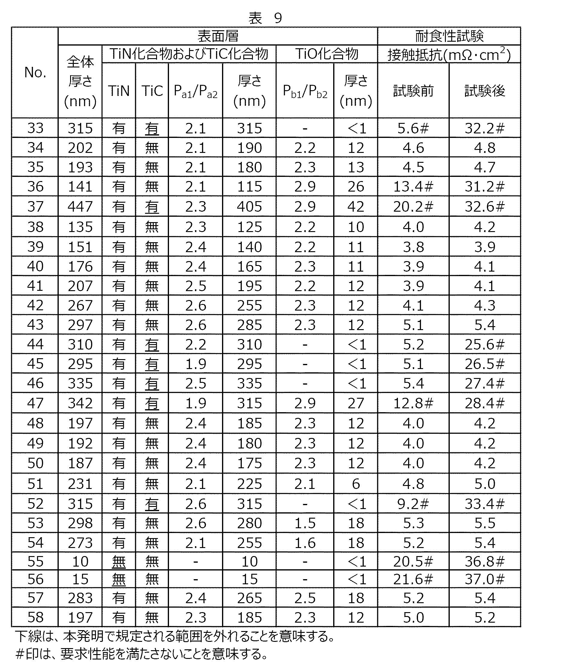
また、No.13のチタン箔について、FIBにて観察用試料を作製し、透過型電子顕微鏡(TEM: Transmission Electron Microscope)を用いて断面を10万倍で観察した際の画像を図2に示す。画像中にスケールバーを示した。
図2(a)において、黒く見える部分が基材層1であって、その上に表面層2が確認される。図2(b)において、実線で囲んだ部分がTiN化合物2aであり、点線で囲んだ部分がTiO化合物2bである。図2(a)(b)に示すように、基材層1の上にTiN化合物2aの層が確認される。TiO化合物2bの層は薄片のTEM像では、コントラストが弱いが、TiNを被覆するTiO化合物層が、厚み数nm程度で、部分的に確認される。本発明では、TiO化合物層の存在は、XPSにおけるTiの2pスペクトルでその存在状態を定量評価した。そして、この実施例3のチタン箔においては、促進劣化試験を行った際の試験前後の接触抵抗の測定結果から、TiO化合物2bの層がTiN化合物2aの層の表面全面を被覆しているものと判断される。 In addition, No. FIG. 2 shows an image obtained by preparing an observation sample by FIB and observing a cross section of the titanium foil No. 13 at a magnification of 100,000 using a transmission electron microscope (TEM). A scale bar is shown in the image.
In FIG. 2A, a portion that looks black is thebase material layer 1, and the surface layer 2 is confirmed thereon. In FIG. 2B, the portion surrounded by the solid line is the TiN compound 2a, and the portion surrounded by the dotted line is the TiO compound 2b. As shown in FIGS. 2A and 2B, a layer of the TiN compound 2a is confirmed on the base material layer 1. Although the TiO compound 2b layer has low contrast in the TEM image of the thin section, the TiO compound layer covering TiN is partially confirmed at a thickness of about several nm. In the present invention, the presence of the TiO compound layer was quantitatively evaluated by a 2p spectrum of Ti in XPS. Then, in the titanium foil of Example 3, from the measurement results of the contact resistance before and after the accelerated deterioration test, the layer of the TiO compound 2b covers the entire surface of the layer of the TiN compound 2a. Is determined.
図2(a)において、黒く見える部分が基材層1であって、その上に表面層2が確認される。図2(b)において、実線で囲んだ部分がTiN化合物2aであり、点線で囲んだ部分がTiO化合物2bである。図2(a)(b)に示すように、基材層1の上にTiN化合物2aの層が確認される。TiO化合物2bの層は薄片のTEM像では、コントラストが弱いが、TiNを被覆するTiO化合物層が、厚み数nm程度で、部分的に確認される。本発明では、TiO化合物層の存在は、XPSにおけるTiの2pスペクトルでその存在状態を定量評価した。そして、この実施例3のチタン箔においては、促進劣化試験を行った際の試験前後の接触抵抗の測定結果から、TiO化合物2bの層がTiN化合物2aの層の表面全面を被覆しているものと判断される。 In addition, No. FIG. 2 shows an image obtained by preparing an observation sample by FIB and observing a cross section of the titanium foil No. 13 at a magnification of 100,000 using a transmission electron microscope (TEM). A scale bar is shown in the image.
In FIG. 2A, a portion that looks black is the
表8および9に示すように、No.2~8、12~14、16~20、22、23、25~27、34、35、38~43、48~51、53、54、57および58は、いずれも基材層の化学組成が本発明で規定される範囲内にあり、Ti化合物がTiN化合物およびTiO化合物を含み、TiCを含まない。このため、促進劣化試験前も試験後も接触抵抗値が5.5mΩ・cm2以下であり、優れた導電性と耐食性を有していた。一方、No.1、9~11、15、21、24、28~33、36、37、44~47、52、55および56は、基材層の化学組成が本発明で規定される範囲を満たさないか、Ti化合物がTiCを含む。このため、いずれの例も、少なくとも、促進劣化試験後の接触抵抗値が5.5mΩ・cm2を超えていた。
As shown in Tables 8 and 9, Each of 2 to 8, 12 to 14, 16 to 20, 22, 23, 25 to 27, 34, 35, 38 to 43, 48 to 51, 53, 54, 57 and 58 has a chemical composition of the base material layer. Within the range defined in the present invention, the Ti compound includes a TiN compound and a TiO compound, and does not include TiC. For this reason, the contact resistance value was 5.5 mΩ · cm 2 or less before and after the accelerated deterioration test, and the film had excellent conductivity and corrosion resistance. On the other hand, No. 1, 9 to 11, 15, 21, 24, 28 to 33, 36, 37, 44 to 47, 52, 55, and 56, whether the chemical composition of the base material layer does not satisfy the range specified in the present invention, The Ti compound contains TiC. Therefore, in any of the examples, at least the contact resistance value after the accelerated deterioration test exceeded 5.5 mΩ · cm 2 .
1 基材層
2 表面層(Ti化合物)
2a TiN化合物
2b TiO化合物
10 焼鈍チタン板材
11 第一酸処理チタン板材11
12 チタン箔
13 第二焼鈍チタン板材
14 チタン箔
20 Ti化合物
21 TiN化合物
22 TiC化合物
23 TiO化合物 1base material layer 2 surface layer (Ti compound)
2a TiN compound 2b TiO compound 10 Annealed titanium plate 11 First acid-treated titanium plate 11
12titanium foil 13 second annealed titanium plate 14 titanium foil 20 Ti compound 21 TiN compound 22 TiC compound 23 TiO compound
2 表面層(Ti化合物)
2a TiN化合物
2b TiO化合物
10 焼鈍チタン板材
11 第一酸処理チタン板材11
12 チタン箔
13 第二焼鈍チタン板材
14 チタン箔
20 Ti化合物
21 TiN化合物
22 TiC化合物
23 TiO化合物 1
12
Claims (9)
- 質量%で、
C:0.080%以下、
H:0.013%以下、
O:0.40%以下、
N:0.050%以下、
Fe:0.50%以下、
残部Tiおよび不純物である化学組成を有する基材層と、
前記基材層の表面に形成された導電性を有する表面層とを備え、
前記表面層は、TiN化合物およびTiO化合物を含み、TiC化合物を含まないTi化合物である、
チタン箔。 In mass%,
C: 0.080% or less,
H: 0.013% or less,
O: 0.40% or less,
N: 0.050% or less,
Fe: 0.50% or less,
A base material layer having a chemical composition that is a balance of Ti and impurities,
With a surface layer having conductivity formed on the surface of the base material layer,
The surface layer is a Ti compound including a TiN compound and a TiO compound, and not including a TiC compound.
Titanium foil. - 前記表面層は、X線回折法で測定したとき、TiN化合物およびTi2N化合物の一方または両方の回折ピークが観測され、これら以外の化合物の回折ピークが観察されず、かつ、表面側からXPSスペクトルを測定したとき、TiO2化合物のピークおよびTiOx化合物の一方または両方のピークが観測され、これら以外のTiのピークが観測されない層である、
請求項1に記載のチタン箔。 In the surface layer, when measured by an X-ray diffraction method, one or both diffraction peaks of a TiN compound and a Ti 2 N compound are observed, no diffraction peak of a compound other than these is observed, and XPS is observed from the surface side. When the spectrum is measured, a layer in which a peak of the TiO 2 compound and one or both peaks of the TiO x compound are observed, and a peak of Ti other than these is not observed,
The titanium foil according to claim 1. - 前記表面層は、厚さが20nm~500nmである、
請求項1または2に記載のチタン箔。 The surface layer has a thickness of 20 nm to 500 nm;
The titanium foil according to claim 1. - 前記表面層は、X線回折スペクトルにおいて、Ti2N化合物のピークPa1とTiN化合物のピークPa2との比(Pa1/Pa2)が1.6~2.6である、
請求項1から3までのいずれかに記載のチタン箔。 The surface layer provides the X-ray diffraction spectrum, the ratio between the peak P a2 of the peak P a1 and TiN compound of Ti 2 N compound (P a1 / P a2) is from 1.6 to 2.6
The titanium foil according to claim 1. - 前記導電性表面層は、Ti2pのXPSスペクトルにおいて、TiO2化合物のピークPb1とTiOx化合物のピークPb2との比(Pb1/Pb2)が1.7~2.8である、
請求項1から4までのいずれかに記載のチタン箔。 The conductive surface layer has a ratio (P b1 / P b2 ) of the peak P b1 of the TiO 2 compound to the peak P b2 of the TiO x compound in the XPS spectrum of Ti 2p of 1.7 to 2.8.
The titanium foil according to any one of claims 1 to 4. - 固体高分子形燃料電池のセパレータに用いられるチタン箔である、
請求項1から5までのいずれかに記載のチタン箔。 A titanium foil used for a polymer electrolyte fuel cell separator,
The titanium foil according to any one of claims 1 to 5. - 請求項1から6までのいずれかに記載のチタン箔の製造方法であって、
(1)圧延油の存在下で冷間圧延されたチタン板材に、窒素ガス雰囲気において光輝焼鈍処理を実施して、前記チタン板材の表面にTi化合物層を形成した焼鈍チタン板材を得る工程と、
(2)前記焼鈍チタン板材に第一酸処理を実施して、前記Ti化合物層中のTiC化合物を除去した第一酸処理チタン板材を得る工程、
(3)前記第一酸処理チタン板材に第二酸処理を実施して、TiN化合物およびTiO化合物を含み、TiC化合物を含まない表面層を備えるチタン箔を得る工程、
を備えるチタン箔の製造方法。 It is a manufacturing method of the titanium foil in any one of Claim 1 to 6, Comprising:
(1) performing a bright annealing treatment in a nitrogen gas atmosphere on a titanium sheet cold-rolled in the presence of a rolling oil to obtain an annealed titanium sheet having a Ti compound layer formed on the surface of the titanium sheet;
(2) performing a first acid treatment on the annealed titanium plate to obtain a first acid-treated titanium plate from which the TiC compound in the Ti compound layer has been removed;
(3) performing a second acid treatment on the first acid-treated titanium plate to obtain a titanium foil including a surface layer containing a TiN compound and a TiO compound and not containing a TiC compound;
A method for producing a titanium foil comprising: - 前記(2)の工程後、前記(3)の工程前に、光揮焼鈍処理を実施する、
請求項7に記載のチタン箔の製造方法。 After the step (2) and before the step (3), a light-volatilizing annealing process is performed;
A method for producing a titanium foil according to claim 7. - 前記(3)の工程が、
酸処理液として、硫酸と過酸化水素との混合溶液、硝酸または過酸化水素酸を用いる、
請求項7または8に記載のチタン箔の製造方法。 The step (3) includes:
As an acid treatment liquid, a mixed solution of sulfuric acid and hydrogen peroxide, nitric acid or hydrogen peroxide is used,
The method for producing a titanium foil according to claim 7.
Priority Applications (1)
| Application Number | Priority Date | Filing Date | Title |
|---|---|---|---|
| PCT/JP2018/034274 WO2020054072A1 (en) | 2018-09-14 | 2018-09-14 | Titanium foil and method for producing same |
Applications Claiming Priority (1)
| Application Number | Priority Date | Filing Date | Title |
|---|---|---|---|
| PCT/JP2018/034274 WO2020054072A1 (en) | 2018-09-14 | 2018-09-14 | Titanium foil and method for producing same |
Publications (1)
| Publication Number | Publication Date |
|---|---|
| WO2020054072A1 true WO2020054072A1 (en) | 2020-03-19 |
Family
ID=69777741
Family Applications (1)
| Application Number | Title | Priority Date | Filing Date |
|---|---|---|---|
| PCT/JP2018/034274 WO2020054072A1 (en) | 2018-09-14 | 2018-09-14 | Titanium foil and method for producing same |
Country Status (1)
| Country | Link |
|---|---|
| WO (1) | WO2020054072A1 (en) |
Citations (6)
| Publication number | Priority date | Publication date | Assignee | Title |
|---|---|---|---|---|
| JPH0568537B2 (en) * | 1984-05-11 | 1993-09-29 | Sumitomo Metal Ind | |
| WO2009034845A1 (en) * | 2007-09-14 | 2009-03-19 | Toyota Jidosha Kabushiki Kaisha | Process for producing separator for fuel cell |
| WO2010038544A1 (en) * | 2008-09-30 | 2010-04-08 | 新日本製鐵株式会社 | Titanium material having low contact resistance for use in separator for solid polymer-type fuel cell and process for producing the titanium material |
| WO2010140700A1 (en) * | 2009-06-01 | 2010-12-09 | 新日本製鐵株式会社 | Titanium-based material responsive to visible light and having excellent photocatalytic activity, and process for producing same |
| WO2011016465A1 (en) * | 2009-08-03 | 2011-02-10 | 新日本製鐵株式会社 | Titanium material for solid polymer fuel cell separator, and process for production thereof |
| JP2018104808A (en) * | 2016-12-28 | 2018-07-05 | 新日鐵住金株式会社 | Titanium material, separator, cell, and solid polymer type fuel cell |
-
2018
- 2018-09-14 WO PCT/JP2018/034274 patent/WO2020054072A1/en active Application Filing
Patent Citations (6)
| Publication number | Priority date | Publication date | Assignee | Title |
|---|---|---|---|---|
| JPH0568537B2 (en) * | 1984-05-11 | 1993-09-29 | Sumitomo Metal Ind | |
| WO2009034845A1 (en) * | 2007-09-14 | 2009-03-19 | Toyota Jidosha Kabushiki Kaisha | Process for producing separator for fuel cell |
| WO2010038544A1 (en) * | 2008-09-30 | 2010-04-08 | 新日本製鐵株式会社 | Titanium material having low contact resistance for use in separator for solid polymer-type fuel cell and process for producing the titanium material |
| WO2010140700A1 (en) * | 2009-06-01 | 2010-12-09 | 新日本製鐵株式会社 | Titanium-based material responsive to visible light and having excellent photocatalytic activity, and process for producing same |
| WO2011016465A1 (en) * | 2009-08-03 | 2011-02-10 | 新日本製鐵株式会社 | Titanium material for solid polymer fuel cell separator, and process for production thereof |
| JP2018104808A (en) * | 2016-12-28 | 2018-07-05 | 新日鐵住金株式会社 | Titanium material, separator, cell, and solid polymer type fuel cell |
Similar Documents
| Publication | Publication Date | Title |
|---|---|---|
| JP5831670B1 (en) | Titanium material or titanium alloy material having surface conductivity, manufacturing method thereof, and fuel cell separator and fuel cell using the same | |
| RU2461100C1 (en) | Titanium material for separator of solid polymer fuel element, which has low contact resistance, and its preparation method | |
| JP6160877B2 (en) | Manufacturing method of fuel cell separator and fuel cell separator | |
| JP5790906B1 (en) | Titanium material or titanium alloy material having surface conductivity, fuel cell separator and fuel cell using the same | |
| KR101804644B1 (en) | Titanium or titanium alloy for fuel cell separator having improved contact conductivity with carbon and durability, fuel cell separator using same, and production method therefor | |
| JP5192908B2 (en) | Titanium substrate for fuel cell separator, fuel cell separator, and fuel cell separator manufacturing method | |
| EP3565042A1 (en) | Titanium material, separator, cell, and solid polymer fuel cell | |
| JP6805822B2 (en) | Titanium material, separator, cell, and polymer electrolyte fuel cell | |
| Zeng et al. | Degradation mechanisms in advanced MEAs for PEM water electrolyzers fabricated by reactive spray deposition technology | |
| JP7056397B2 (en) | Titanium material, separator, cell, and fuel cell stack | |
| JP2011038166A (en) | Energizing member for fuel cell and method for producing the same | |
| US8834734B2 (en) | Surface alloying of stainless steel | |
| WO2020054072A1 (en) | Titanium foil and method for producing same | |
| EP3252856B1 (en) | Stainless steel sheet for separator of polymer electrolyte fuel cell | |
| JP7421101B2 (en) | Titanium materials, fuel cell separators, fuel cells, and fuel cell stacks | |
| JP2010238394A (en) | Separator material for fuel cell and fuel cell stack using the same |
Legal Events
| Date | Code | Title | Description |
|---|---|---|---|
| 121 | Ep: the epo has been informed by wipo that ep was designated in this application |
Ref document number: 18933155 Country of ref document: EP Kind code of ref document: A1 |
|
| NENP | Non-entry into the national phase |
Ref country code: DE |
|
| 122 | Ep: pct application non-entry in european phase |
Ref document number: 18933155 Country of ref document: EP Kind code of ref document: A1 |
|
| NENP | Non-entry into the national phase |
Ref country code: JP |