WO2020050100A1 - 物理量計測装置及び物理量計測装置の製造方法 - Google Patents
物理量計測装置及び物理量計測装置の製造方法 Download PDFInfo
- Publication number
- WO2020050100A1 WO2020050100A1 PCT/JP2019/033531 JP2019033531W WO2020050100A1 WO 2020050100 A1 WO2020050100 A1 WO 2020050100A1 JP 2019033531 W JP2019033531 W JP 2019033531W WO 2020050100 A1 WO2020050100 A1 WO 2020050100A1
- Authority
- WO
- WIPO (PCT)
- Prior art keywords
- physical quantity
- support plate
- detection
- hole
- concave
- Prior art date
- Legal status (The legal status is an assumption and is not a legal conclusion. Google has not performed a legal analysis and makes no representation as to the accuracy of the status listed.)
- Ceased
Links
Images













Classifications
-
- G—PHYSICS
- G01—MEASURING; TESTING
- G01F—MEASURING VOLUME, VOLUME FLOW, MASS FLOW OR LIQUID LEVEL; METERING BY VOLUME
- G01F1/00—Measuring the volume flow or mass flow of fluid or fluent solid material wherein the fluid passes through a meter in a continuous flow
- G01F1/68—Measuring the volume flow or mass flow of fluid or fluent solid material wherein the fluid passes through a meter in a continuous flow by using thermal effects
- G01F1/684—Structural arrangements; Mounting of elements, e.g. in relation to fluid flow
-
- F—MECHANICAL ENGINEERING; LIGHTING; HEATING; WEAPONS; BLASTING
- F02—COMBUSTION ENGINES; HOT-GAS OR COMBUSTION-PRODUCT ENGINE PLANTS
- F02M—SUPPLYING COMBUSTION ENGINES IN GENERAL WITH COMBUSTIBLE MIXTURES OR CONSTITUENTS THEREOF
- F02M35/00—Combustion-air cleaners, air intakes, intake silencers, or induction systems specially adapted for, or arranged on, internal-combustion engines
- F02M35/10—Air intakes; Induction systems
- F02M35/10373—Sensors for intake systems
- F02M35/10386—Sensors for intake systems for flow rate
-
- G—PHYSICS
- G01—MEASURING; TESTING
- G01F—MEASURING VOLUME, VOLUME FLOW, MASS FLOW OR LIQUID LEVEL; METERING BY VOLUME
- G01F1/00—Measuring the volume flow or mass flow of fluid or fluent solid material wherein the fluid passes through a meter in a continuous flow
- G01F1/68—Measuring the volume flow or mass flow of fluid or fluent solid material wherein the fluid passes through a meter in a continuous flow by using thermal effects
- G01F1/684—Structural arrangements; Mounting of elements, e.g. in relation to fluid flow
- G01F1/6842—Structural arrangements; Mounting of elements, e.g. in relation to fluid flow with means for influencing the fluid flow
-
- G—PHYSICS
- G01—MEASURING; TESTING
- G01F—MEASURING VOLUME, VOLUME FLOW, MASS FLOW OR LIQUID LEVEL; METERING BY VOLUME
- G01F1/00—Measuring the volume flow or mass flow of fluid or fluent solid material wherein the fluid passes through a meter in a continuous flow
- G01F1/68—Measuring the volume flow or mass flow of fluid or fluent solid material wherein the fluid passes through a meter in a continuous flow by using thermal effects
- G01F1/684—Structural arrangements; Mounting of elements, e.g. in relation to fluid flow
- G01F1/6845—Micromachined devices
-
- G—PHYSICS
- G01—MEASURING; TESTING
- G01F—MEASURING VOLUME, VOLUME FLOW, MASS FLOW OR LIQUID LEVEL; METERING BY VOLUME
- G01F1/00—Measuring the volume flow or mass flow of fluid or fluent solid material wherein the fluid passes through a meter in a continuous flow
- G01F1/68—Measuring the volume flow or mass flow of fluid or fluent solid material wherein the fluid passes through a meter in a continuous flow by using thermal effects
- G01F1/684—Structural arrangements; Mounting of elements, e.g. in relation to fluid flow
- G01F1/688—Structural arrangements; Mounting of elements, e.g. in relation to fluid flow using a particular type of heating, cooling or sensing element
- G01F1/69—Structural arrangements; Mounting of elements, e.g. in relation to fluid flow using a particular type of heating, cooling or sensing element of resistive type
- G01F1/692—Thin-film arrangements
-
- G—PHYSICS
- G01—MEASURING; TESTING
- G01F—MEASURING VOLUME, VOLUME FLOW, MASS FLOW OR LIQUID LEVEL; METERING BY VOLUME
- G01F1/00—Measuring the volume flow or mass flow of fluid or fluent solid material wherein the fluid passes through a meter in a continuous flow
- G01F1/68—Measuring the volume flow or mass flow of fluid or fluent solid material wherein the fluid passes through a meter in a continuous flow by using thermal effects
- G01F1/696—Circuits therefor, e.g. constant-current flow meters
-
- G—PHYSICS
- G01—MEASURING; TESTING
- G01F—MEASURING VOLUME, VOLUME FLOW, MASS FLOW OR LIQUID LEVEL; METERING BY VOLUME
- G01F5/00—Measuring a proportion of the volume flow
Definitions
- the present disclosure relates to a physical quantity measuring device and a method of manufacturing the physical quantity measuring device.
- Patent Document 1 discloses a thermal flow meter having a flow rate detecting element for detecting a flow rate of air and a metal substrate on which the flow rate detecting element is mounted. .
- a gap is formed on the back surface side of the thinned diaphragm, and the metal substrate is overlaid on the back surface of the flow detecting element so as to cover the opening of the gap. Since the air holes communicating with the gaps are formed in the metal substrate, the air pressure acting on the front surface and the back surface of the diaphragm becomes equal. The periphery of the air hole is overlapped with the periphery of the gap on the back surface of the flow rate detecting element.
- the main purpose of the present disclosure is to improve the detection accuracy of the physical quantity detection unit by forming a communication hole in the support plate portion that supports the physical quantity detection unit, and then the burr is formed on the support plate unit with the formation of the communication hole. It is an object of the present invention to provide a physical quantity measuring device and a method of manufacturing the physical quantity measuring device, which can suppress the contact of the burr with the physical quantity detecting unit even if it occurs.
- the physical quantity detection unit includes a concave portion formed by denting the back surface of the physical quantity detection unit, and a membrane portion that forms a bottom surface of the concave portion in the physical quantity detection unit and is provided with a detection element for detecting a physical quantity of a fluid.
- a portion of the support plate portion that covers the recess is provided with a communication hole that penetrates the support plate portion and communicates with the recess, and a peripheral edge of a hole opening that is an end of the communication hole on the recess side. Are inwardly spaced from the periphery of the concave opening, which is the end on the support plate portion side, in the concave portion.
- the periphery of the hole opening provided in the support plate is separated inward from the periphery of the concave opening provided in the physical quantity detection unit.
- the position where the burr is separated inward from the periphery of the concave opening Will exist. Therefore, it is possible to prevent the burr from coming into contact with the back surface of the physical quantity detection unit.
- the communication hole is formed in the support plate portion, a pressure difference between the inside and the outside of the concave portion is hardly generated, so that the membrane portion is deformed due to the pressure difference between the inside and the external portion of the concave portion. Therefore, it is possible to prevent the detection accuracy of the physical quantity detection unit from being reduced. Therefore, by forming the communication hole in the support plate, the detection accuracy of the physical quantity detection unit is improved, and the contact of the burr with the physical quantity detection unit can be suppressed. As a result, the physical quantity detector is less likely to be damaged by contact with the burr.
- a concave portion formed by denting the back surface which is one surface of the portion, and a membrane portion provided with a detecting element for detecting a physical quantity of the fluid and forming a bottom surface of the concave portion in the physical quantity detecting section.
- the communication hole communicates with the recess in a state where the peripheral edge of the hole opening that is the end of the communication hole on the concave side is separated inward from the peripheral edge of the recess opening that is the end of the support plate on the concave side.
- To the support plate Kicking and a attaching a physical quantity detecting unit in the table plate surface is a plate surface opposite to the back plate surface.
- the communication hole is formed by punching the support plate from the back surface
- burrs generated by punching of the support plate are formed around the periphery of the communication hole on the front surface side of the support plate. It is feared that it remains in the department.
- the physical quantity detection unit is attached to the surface of the support plate so that the periphery of the hole opening provided in the support plate is separated inward from the periphery of the concave opening provided in the physical quantity detection unit. . For this reason, even if burrs remain on the periphery of the communication hole on the front surface side of the support plate portion, the burrs will be present at a position spaced inward from the periphery of the concave opening. Therefore, the same effect as in the first aspect can be obtained.
- FIG. 1 is a diagram illustrating a configuration of a combustion system according to a first embodiment.
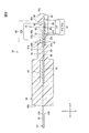
- FIG. 3 is a longitudinal sectional view of the air flow meter attached to an intake pipe.
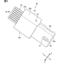
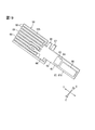
- FIG. 3 is a perspective view showing the internal structure of a sensor SA.
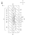
- FIG. 3 is a front view showing the internal structure of the sensor SA.
- FIG. 8 is a sectional view taken along line VIII-VIII of FIG. 7. IX-IX sectional drawing of FIG.
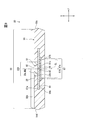
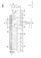
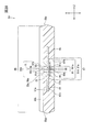
- FIG. 9 is an enlarged view around the flow rate detection unit in FIG. 8.
- FIG. 2 is a circuit diagram showing a configuration of a flow detection circuit.
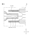
- FIG. 3 is a plan view showing a positional relationship between an air temperature resistance and a membrane unit in a flow detection unit.
- FIG. 13 is an enlarged view of the vicinity of the membrane in FIG. 12.
- FIG. 15 is an enlarged view around the SA substrate in FIG. 14.
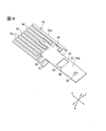
- FIG. 4 is a perspective view of the SA board with the chip component attached, as viewed from the front side. The top view which looked at the base material in the state where the mold part was attached to the SA substrate from the front side.
- FIG. 3 is a longitudinal sectional view showing a configuration of a mold device.
- FIG. 24 is a sectional view taken along line XXIV-XXIV of FIG. 23.
- FIG. 10 is a vertical cross-sectional view of a sensor SA according to the second embodiment.
- FIG. 26 is a sectional view taken along the line XXVI-XXVI in FIG. 25.
- FIG. 13 is a longitudinal sectional view of a sensor SA according to a third embodiment.
- FIG. 28 is a sectional view taken along line XXVIII-XXVIII in FIG. 27.
- a combustion system 10 shown in FIG. 1 includes an internal combustion engine 11 such as a gasoline engine, an intake passage 12, an exhaust passage 13, an air flow meter 20, and an ECU 15, and is mounted on, for example, a vehicle.
- the air flow meter 20 is provided in the intake passage 12 and measures a flow rate of intake air supplied to the internal combustion engine 11, a physical quantity such as temperature, humidity, and pressure.
- the air flow meter 20 corresponds to a physical quantity measuring device for measuring a fluid such as intake air.
- the intake air is a gas supplied to the combustion chamber 11a of the internal combustion engine 11. In the combustion chamber 11a, a mixture of intake air and fuel is ignited by a spark plug 17.
- the ECU (Engine Control Unit) 15 is a control device that controls the operation of the combustion system 10.
- the ECU 15 is an arithmetic processing circuit including a processor, a storage medium such as a RAM, a ROM, and a flash memory, and a microcomputer including an input / output unit, a power supply circuit, and the like.
- the ECU 15 receives a sensor signal output from the air flow meter 20, a sensor signal output from a number of in-vehicle sensors, and the like.
- the ECU 15 performs engine control on the fuel injection amount, the EGR amount, and the like of the injector 16 using the measurement result by the air flow meter 20.
- the ECU 15 is a control device that controls the operation of the internal combustion engine 11, and the combustion system 10 can also be referred to as an engine control system.
- the ECU 15 corresponds to an external device.
- the combustion system 10 has a plurality of measurement units as on-vehicle sensors.
- the measuring unit includes a throttle sensor 18a, an intake pressure sensor 18b, a water temperature sensor 18c, a crank angle sensor 18d, an air-fuel ratio sensor 18e, a knock sensor 18f, a cam angle sensor 18g, and the like.
- Each of these measuring units is electrically connected to the ECU 15 and outputs a detection signal to the ECU 15.
- the air flow meter 20 is provided in the intake passage 12 on the upstream side of a throttle valve to which the throttle sensor 18a is attached.
- the air flow meter 20 is attached to an intake pipe 12a such as a duct forming the intake passage 12.
- the intake pipe 12a is provided with an airflow insertion hole 12b as a through hole penetrating the outer peripheral portion.
- An annular pipe flange 12c is attached to the airflow insertion hole 12b, and the pipe flange 12c is included in the intake pipe 12a.
- the air flow meter 20 is inserted into the pipe flange 12c and the air flow insertion hole 12b to enter the intake passage 12, and is fixed to the intake pipe 12a and the pipe flange 12c in this state.
- the width direction X, the height direction Y, and the depth direction Z are defined for the air flow meter 20, and these directions X, Y, and Z are orthogonal to each other.
- the air flow meter 20 extends in the height direction Y, and the intake passage 12 extends in the depth direction Z.
- the air flow meter 20 has an entry portion 20a that has entered the intake passage 12, and an extension portion 20b that has not entered the intake passage 12 and has protruded from the pipe flange 12c.
- the entry portion 20a and the extension portion 20b Are arranged in the height direction Y.
- the one included in the entry portion 20 a is referred to as an air flow front end surface 20 c
- the one included in the protrusion portion 20 b is the air flow base end surface. 20d.
- the airflow front end surface 20c and the airflow base end surface 20d are orthogonal to the height direction Y.
- the distal end face of the pipe flange 12c is also orthogonal to the height direction Y.
- the air flow meter 20 includes a housing 21, a flow rate detection unit 22 that detects a flow rate of intake air, and an intake air temperature sensor (not shown) that detects a temperature of the intake air. ing.
- the housing 21 is formed of, for example, a resin material.
- the housing 21 is attached to the intake pipe 12 a, so that the flow detection unit 22 can come into contact with the intake air flowing through the intake passage 12.
- the housing 21 has a housing main body 24, a ring holding portion 25, a flange portion 27, and a connector portion 28, and an O-ring 26 is attached to the ring holding portion 25.
- the housing body 24 is formed in a cylindrical shape as a whole, and in the housing 21, the ring holding section 25, the flange section 27 and the connector section 28 are provided integrally with the housing body 24.
- the ring holding part 25 is included in the entry part 20a, and the flange part 27 and the connector part 28 are included in the protrusion part 20b.
- the ring holding portion 25 is provided inside the pipe flange 12c, and holds the O-ring 26 so as not to be displaced in the height direction Y.
- the O-ring 26 is a sealing member that seals the intake passage 12 inside the pipe flange 12c, and is in close contact with both the outer peripheral surface of the ring holding portion 25 and the inner peripheral surface of the pipe flange 12c.
- a fixing hole such as a screw hole for fixing a fixing tool such as a screw for fixing the air flow meter 20 to the intake pipe 12a is formed in the flange portion 27.
- the connector unit 28 is a protection unit that protects the connector terminal 28a electrically connected to the flow detection unit 22.
- the flow rate detection unit 22 is provided in the internal space 24 a of the housing main body 24, and the intake air temperature sensor is provided outside the housing 21.
- the intake air temperature sensor has a temperature sensing element for sensing the temperature of the intake air, a lead wire extending from the temperature sensing element, and an intake temperature terminal connected to the lead wire.
- the housing 21 has a support for supporting the intake air temperature sensor, and this support is provided on the outer peripheral side of the housing 21.
- the housing body 24 forms a bypass passage 30 into which a part of the intake air flowing through the intake passage 12 flows.
- the bypass flow path 30 is arranged at the entry portion 20 a of the air flow meter 20.
- the bypass passage 30 has a passage passage 31 and a measurement passage 32, and the passage passage 31 and the measurement passage 32 are formed by the internal space 24 a of the housing main body 24.
- the intake passage 12 may be referred to as a main passage
- the bypass passage 30 may be referred to as a sub passage.
- the passage 31 penetrates the housing body 24 in the depth direction Z.
- the passage 31 has an inlet 33 at an upstream end and an outlet 34 at a downstream end.
- the measurement flow path 32 is a branch flow path branched from an intermediate portion of the passage flow path 31, and the flow rate detection unit 22 is provided in the measurement flow path 32.
- the measurement flow path 32 has a measurement inlet 35 which is an upstream end thereof, and a measurement outlet 36 which is a downstream end thereof.
- the portion where the measurement channel 32 branches off from the passage channel 31 is the boundary between the passage channel 31 and the measurement channel 32, and the boundary includes the measurement inlet 35.
- the measurement entrance 35 corresponds to the branch entrance
- the measurement exit 36 corresponds to the branch exit.
- the boundary between the passage channel 31 and the measurement channel 32 may be referred to as a channel boundary.
- the flow rate detection unit 22 is a thermal flow rate sensor having a heater unit. When a temperature change occurs due to the heat generation of the heater unit, the flow detection unit 22 outputs a detection signal corresponding to the temperature change.
- the flow detection unit 22 is a rectangular parallelepiped chip component, and the flow detection unit 22 may be referred to as a sensor chip.
- the flow detection unit 22 corresponds to a physical quantity detection unit that detects the flow rate of the intake air as a physical quantity of the fluid.
- the air flow meter 20 has a sensor sub-assembly including the flow rate detecting unit 22, and this sensor sub-assembly is referred to as a sensor SA50.
- the sensor SA50 is housed in the internal space 24a of the housing main body 24. Note that the sensor SA50 may be referred to as a detection unit, a measurement unit, or a sensor package.
- the sensor SA50 has an entry portion 50a that has entered the measurement flow channel 32 in the internal space 24a, and a protruding portion 50b that has entered the measurement flow channel 32 without entering the measurement flow channel 32.
- the entering part 50a and the protruding part 50b are arranged in the height direction Y, and the flow rate detecting unit 22 is included in the entering part 50a.
- the sensor SA50 includes an SA substrate 53 on which the flow detection unit 22 is mounted, a flow processing unit 54 electrically connected to the flow detection unit 22, a SA substrate 53, and a flow detection unit. 22 and a mold section 55 covering the flow rate processing section 54.
- a detection signal is input to the flow rate processing unit 54 as a detection result of the flow rate detection unit 22, and the flow rate detection unit 22 corresponds to a physical quantity processing unit.
- the SA substrate 53 corresponds to a support plate portion
- the mold portion 55 corresponds to a body for protecting the physical quantity detection section and the physical quantity processing section.
- the SA substrate may be referred to as a lead frame.
- the mold part 55 is shown by a virtual line in order to illustrate the internal structure of the sensor SA50.
- the mold part 55 is formed in a plate shape as a whole. As shown in FIG. 3, in the mold portion 55, of the pair of end surfaces 55 a and 55 b arranged in the height direction Y, the one included in the entry portion 50 a is referred to as a mold front end surface 55 a, and the one included in the protrusion portion 50 b. The one that is referred to as a mold base end face 55b. Further, one of a pair of surfaces provided between the mold distal end surface 55a and the mold base end surface 55b is referred to as a mold upstream surface 55c, and the other is referred to as a mold downstream surface 55d.
- the sensor SA50 is installed in the internal space 24a in such a direction that the mold tip surface 55a is arranged on the airflow tip surface 20c side and the mold upstream surface 55c is arranged on the upstream side of the measurement flow path 32 from the mold downstream surface 55d. ing.
- the mold upstream surface 55c of the sensor SA50 is disposed upstream of the mold downstream surface 55d in the measurement flow path 32.
- the direction of air flow is opposite to the direction of air flow in the intake passage 12. For this reason, the mold upstream surface 55c is located downstream of the mold downstream surface 55d in the intake passage 12.
- the SA substrate 53 is a conductive substrate that is formed as a whole from a metal material or the like into a plate shape.
- the plate surface of the SA substrate 53 is orthogonal to the width direction X, and extends in the height direction Y and the depth direction Z.
- the SA substrate 53 includes a detection frame 61 that supports the flow rate detection unit 22, a processing frame 62 that supports the flow rate processing unit 54, a connection frame 63 that connects the frames 61 and 62, and a lead that is connected to the connector terminal 28a. Terminals 64 and 65 are provided.
- the detection frame 61 corresponds to a detection support section
- the processing frame 62 corresponds to a processing support section
- the connection frame 63 corresponds to a connection support section.
- the detection frame 61 corresponds to a portion of the SA substrate 53 covering the concave portion, and is also referred to as a covering portion.
- the detection frame 61 and the processing frame 62 are both formed in a rectangular shape as a whole, and their respective plate surfaces are orthogonal to the width direction X.
- the detection frame 61 is provided at a position separated from the processing frame 62 toward the mold front end face 55a.
- a pair of connection frames 63 are provided between the detection frame 61 and the processing frame 62 in the height direction Y, and each connection frame 63 is in a state of being bridged between the detection frame 61 and the processing frame 62. ing.
- the pair of connection frames 63 are arranged in the depth direction Z while being separated from each other.
- a substrate hole 69 is formed in the SA substrate 53 as a through hole penetrating the SA substrate 53 in the width direction X.
- the substrate hole 69 is provided between the detection frame 61 and the processing frame 62 in the height direction Y, and forms a space between the frames 61 and 62.
- the board hole 69 is provided between the pair of connection frames 63 in the depth direction Z, and forms a separated portion between the connection frames 63.
- the substrate hole 69 is disposed between the flow detection unit 22 and the flow processing unit 54 in the height direction Y.
- the substrate holes 69 are provided in the SA substrate 53, the sum of the cross-sectional areas of the pair of connection frames 63 in the cross-sectional area in the direction orthogonal to the height direction Y is the cross-sectional area of the detection frame 61 and the processing frame. 62 are smaller than any of the cross-sectional areas. For this reason, heat is less transmitted to the connection frame 63 than to both the detection frame 61 and the processing frame 62. Note that the substrate hole 69 corresponds to a through portion.
- both the flow detection unit 22 and the flow processing unit 54 are mounted on one plate surface, and the flow detection unit 22 and the flow processing unit 54 are mounted.
- a front surface 53a Is referred to as a front surface 53a
- the plate surface opposite to the front surface 53a is referred to as a back surface 53b.
- the front surface 53a of the SA substrate 53 includes the front surface 61a of the detection frame 61
- the rear surface 53b of the SA substrate 53 includes the rear surface 61b of the detection frame 61.
- the front surface 61a and the rear surface 61b are parallel to each other. Extending.
- the front surface 61a corresponds to the front plate surface
- the back surface 61b corresponds to the back plate surface.
- the flow rate detection unit 22 is formed in a plate shape.
- a plate surface opposite to the detection frame 61 is referred to as a front surface 22a
- a plate surface opposite to the front surface 22a is referred to as a back surface 22b. Called. Both the front surface 22a and the back surface 22b extend in parallel with each other.
- the back surface 22 b of the flow rate detection unit 22 is overlaid on the front surface 61 a of the detection frame 61.
- both side ends of the substrate hole 69 are disposed at positions protruding outside of both the flow rate detection unit 22 and the flow rate processing unit 54.
- the pair of connection frames 63 is not disposed at a position interposed between the flow rate detection unit 22 and the flow rate processing unit 54, and is not disposed in the width direction X and the depth direction Z. It is arranged at a position shifted laterally from the section 22 and the flow rate processing section 54.
- the detection frame 61, the processing frame 62, and the substrate hole 69 are arranged in the height direction Y, and the center line of the detection frame 61, the processing frame 62, and the substrate hole 69 coincides with the virtual axis extending in the height direction Y. ing.
- the flow detection unit 22 is disposed at the center position of the detection frame 61, and the flow processing unit 54 is disposed at the center position of the processing frame 62.
- the width W1 of the detection frame 61 and the width W2 of the processing frame 62 are the same.
- the width dimension W3 of the flow rate detection unit 22 is smaller than the width dimension W4 of the flow rate processing unit 54, and the width dimension W5 of the substrate hole 69 is larger than these width dimensions W3 and W4.
- the width dimension W5 of the substrate hole 69 is the distance between the pair of connection frames 63.
- the length dimension H1 of the substrate hole 69 is such that heat is hardly transmitted between the detection frame 61 and the processing frame 62.
- the detection frame 61 has a detection extension portion 68a which extends to the substrate hole 69 side from the flow rate detection portion 22, and the processing frame 62 extends to the frame 61 side from the flow rate processing portion 54. It has an extended processing extension 68b.
- the length dimension H1 of the substrate hole 69 is determined by either the extension dimension H2 of the detection extension section 68a from the flow rate detection section 22 or the extension dimension H3 of the processing extension section 68b from the flow rate processing section 54. Is also getting bigger.
- the length dimension H1 of the substrate hole 69 is larger than the sum of the extension dimensions H2 and H3. Further, in the height direction Y, the substrate hole 69 is disposed at the center between the flow detection unit 22 and the flow processing unit 54, and the extension H2 of the detection extension 68a and the extension of the processing extension 68b. H2 has almost the same value.
- the lead terminals 64 and 65 project from the mold base end face 55b to the outside of the mold portion 55.
- portions protruding outside the mold portion 55 extend in the height direction Y from the mold base end face 55b, and are connected to the connector terminals 28a in the internal space 24a of the housing body 24.
- the back surface 53b of the SA substrate 53 includes the back surfaces of the lead terminals 64 and 65, and the back surfaces of the lead terminals 64 and 65 are in contact with the connector terminals 28a.
- the ground lead terminal 64 extends from the processing frame 62 and is electrically connected to the ground terminal in the sensor SA50.
- the detection frame 61 and the connection frame 63 are also grounded via the processing frame 62.
- the ground lead terminal 64 corresponds to a support terminal.
- the circuit lead terminal 65 is electrically connected to the flow rate processing unit 54 while being separated from the processing frame 62 inside the mold unit 55.
- a plurality of ground lead terminals 64 and a plurality of circuit lead terminals 65 are provided.
- the plurality of circuit lead terminals 65 include a power supply terminal that supplies power to a power supply terminal in the sensor SA50, and a signal terminal that inputs and outputs signals to and from the signal terminal in the sensor SA50.
- the sensor SA50 has a protection chip 71 for protecting the flow rate processing unit 54 from noise.
- the protection chip 71 is a chip component having a protection circuit including a capacitor, and is provided so as to extend between the ground lead terminal 64 and the circuit lead terminal 65 inside the molded portion 55.
- the SA substrate 53 has protection frames 66 and 67 to which the protection chip 71 is attached.
- the ground protection frame 66 extends from the processing frame 62.
- the circuit protection frame 67 is separated from the processing frame 62 inside the mold section 55, while being electrically connected to the flow processing section 54.
- the protection chip 71 is provided so as to extend over the ground protection frame 66 and the circuit protection frame 67 or the circuit lead terminal 65.
- the flow rate processing unit 54 has a drive circuit such as a digital circuit (see FIG. 11) for performing various processes.
- the flow rate processing unit 54 is a rectangular parallelepiped chip component, and the flow rate processing unit 54 may be referred to as a circuit chip. It is electrically connected to the flow detection unit 22, the circuit lead terminal 65, and the circuit protection frame 67 via a bonding wire 72.
- the mold unit 55 covers the protection chip 71 and the bonding wire 72 in addition to the flow detection unit 22 and the flow processing unit 54, so that the flow detection unit 22, the flow processing unit 54, the protection chip 71, and the bonding wire 72 Is protected.
- the mold portion 55 can be referred to as a protective body.
- the mold part 55 is a mold resin such as a polymer resin molded by molding, and has higher insulation and heat insulation than the SA substrate 53.
- the mold section 55 integrally seals the flow processing section 54, the protection chip 71, the bonding wires 72, and the like.
- the mold section 55 has a frame regulating section 81 which regulates transmission of heat from the processing frame 62 to the detection frame 61.
- the frame restricting portion 81 is a portion of the mold portion 55 that has entered the substrate hole 69, and is in a state of being filled in the substrate hole 69. For this reason, the frame restricting portion 81 has the same size and shape as the substrate hole 69.
- the width dimension of the frame regulating portion 81 in the depth direction Z is the same as the width dimension W5 of the substrate hole 69.
- the frame restricting portions 81 are arranged side by side on the connection frame 63 in the depth direction Z. In this case, the frame regulating portion 81 and the connection frame 63 are arranged side by side along the plate surface of the SA substrate 53. Note that the frame restricting portion 81 corresponds to a heat transfer restricting portion.
- the detected value of the flow rate detection unit 22 tends to be unstable until the temperature of the flow rate detection unit 22 is stabilized at a temperature corresponding to the heat transmitted from the flow rate processing unit 54.
- the activation of the air flow meter 20 is poorly specified, and the responsiveness of the flow rate detection unit 22 tends to deteriorate for a while after the power is turned on.
- the frame restricting portion 81 since the frame restricting portion 81 is provided on the entire substrate hole 69, the heat of the flow processing portion 54 is transmitted to the flow detecting portion 22 through the SA substrate 53.
- the transmission is regulated by the frame regulating unit 81.
- the mold section 55 has, in addition to the frame restricting section 81, a direct restricting section 82 which is a portion inserted between the flow rate processing section 54 and the flow rate detecting section 22 in the height direction Y.
- the direct restricting section 82 is a part that restricts the transfer of heat directly from the flow processing section 54 to the flow detecting section 22 without passing through the SA substrate 53.
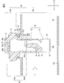
- the flow rate detection unit 22 has a detection recess 91 formed by recessing the back surface 22 b thereof, and a membrane portion 92 forming a bottom surface 91 a of the detection recess 91. ing.
- the detection recess 91 has a bottom surface 91a facing the detection frame 61 side and an inner wall surface 91b extending from the bottom surface 91a toward the detection frame 61 side.
- the detection concave portion 91 has a concave opening 91c which is an opening that opens the internal space of the detection concave portion 91 toward the side opposite to the bottom surface 91a.
- the concave opening 91c is provided on the back surface 22b of the flow rate detecting portion 22. Is formed.
- the detection recess 91 is covered by the detection frame 61, and the bottom surface 91 a faces the front surface 61 a of the detection frame 61.
- the detection concave portion 91 corresponds to a concave portion.
- the internal space of the detection concave portion 91 is hollow, and the detection concave portion 91 can also be referred to as a hollow portion or a void portion.
- the center line CL of the detection concave portion 91 extends in the width direction X, and is orthogonal to the front surface 22a and the rear surface 22b of the flow detection unit 22.
- the detection concave portion 91 is tapered from the concave opening 91c toward the bottom surface 91a, and is formed in a tapered shape as a whole by the inner wall surface 91b extending straight from the concave opening 91c toward the bottom surface 91a.
- the internal space of the detection recess 91 gradually decreases in the width direction X toward the bottom surface 91a, and the detection recess 91 is tapered as a whole.
- the cross-sectional area in the direction orthogonal to the center line CL gradually increases from the bottom surface 91a toward the concave opening 91c.
- the inner wall surface 91b is not parallel to the center line CL, but is inclined with respect to the center line CL by facing the concave opening 91c side.
- the detection recess 91 has two pairs of inner wall surfaces 91b facing each other, so that the bottom surface 91a and the recess opening 91c are formed in a rectangular shape.
- the open area of the concave opening 91c is larger than the area of the bottom surface 91a.
- the end on the back surface 22b side forms the peripheral edge of the concave opening 91c
- the end on the front surface 22a side forms the peripheral edge of the bottom surface 91a.
- the distance between a pair of sides facing each other in the peripheral edge of the concave opening 91c is referred to as an opening dimension L1 of the concave opening 91c, and is opposed to each other in the peripheral edge of the bottom surface 91a.
- the distance between the pair of sides is referred to as a bottom dimension L2.
- the concave opening 91c and the bottom surface 91a are both square, and the opening size L1 and the bottom size L2 are the same for both the pair of sides arranged in the height direction Y and the pair of sides arranged in the depth direction Z. ing.
- the opening dimension L1 of the concave opening 91c is larger than the bottom dimension L2 of the bottom surface 91a.
- the illustration of the mold section 55 is omitted, and the membrane section 92 is shown thicker than it actually is.
- the membrane portion 92 is provided on the front side of the detection concave portion 91 in the width direction X, and is a film-like portion thinned by the detection concave portion 91 in the flow rate detection portion 22.
- the front surface of the membrane portion 92 is formed by the front surface 22 a of the flow rate detection portion 22, and the back surface is formed by the bottom surface 91 a of the detection concave portion 91.
- the membrane portion 92 is not disposed between the front surface 22a and the back surface 22b in the flow rate detection portion 22, but is disposed on the front surface 22a.
- the membrane unit 92 has a plurality of detection elements, and serves as a sensor unit that detects the flow rate of air in the flow rate detection unit 22.
- the shape and size of the membrane portion 92 are the same as the shape and size of the detection concave portion 91. Specifically, when the distance between a pair of sides facing each other in the peripheral portion of the membrane portion 92 is referred to as a membrane dimension, the membrane dimension is the same as the bottom dimension L2. Further, the membrane portion 92 has a square shape like the detection concave portion 91, and the membrane dimensions are the same for both a pair of sides arranged in the height direction Y and a pair of sides arranged in the depth direction Z. I have.
- a detection frame hole 95 communicating with the internal space of the detection concave portion 91 is provided in a portion of the detection frame 61 covering the concave opening 91c of the detection concave portion 91.
- the detection frame hole 95 is a through hole that penetrates the detection frame 61 in the width direction X, and is a circular hole having a circular cross section.
- the center line of the detection frame hole 95 coincides with the center line CL of the detection recess 91.
- the detection frame hole 95 has a front opening 95a which is an end on the surface 61a side.
- the boundary between the detection concave portion 91 and the detection frame hole 95 includes a concave opening 91c and a front opening 95a. Note that the detection frame 61 corresponds to a portion covering the detection concave portion 91, the detection frame hole 95 corresponds to a communication hole, and the front opening 95a corresponds to a hole opening.
- the peripheral edge of the front opening 95a is located at a position separated from the peripheral edge of the concave opening 91c toward the center line CL on the inner peripheral side.
- the front opening 95a is smaller than the concave opening 91c.
- the inner diameter L3 of the front opening 95a is smaller than the opening dimension L1 of the concave opening 91c.
- the inner diameter L3 of the front opening 95a is equivalent to a separation distance of a portion where the separation distance is the shortest among portions facing each other across the center line CL in a peripheral portion of the front opening 95a.
- the center of the front opening 95a is a portion through which the center line CL passes.
- the thickness of the detection frame hole 95 is uniform in any part in the width direction X, and the inner diameter of the detection frame hole 95 is the same as the inner diameter L3 of the front opening 95a.
- the peripheral edge of the front opening 95a is located at a position spaced inward from the peripheral edge of the bottom surface 91a of the detection concave portion 91. That is, the peripheral edge of the front opening 95 a is located at a position separated from the membrane 92 to the inner peripheral side.
- the front opening 95a is an opening smaller than the bottom surface 91a.
- the inside diameter L3 of the front opening 95a is smaller than the bottom dimension L2 of the bottom surface 91a.
- the detection frame hole 95 is formed in the detection frame 61
- burrs which are unnecessary projections, remain on the periphery of the detection frame hole 95.
- the detection frame hole 95 is formed by punching or pressing
- burrs extending from the front surface 61a may be generated at the peripheral portion of the front opening 95a. Is assumed.
- the burrs come into contact with the back surface 22b of the flow detection unit 22, there is a concern that the detection accuracy of the flow detection unit 22 may be reduced due to damage or breakage of the flow detection unit 22.
- the peripheral edge of the front opening 95a is located inside the peripheral edge of the concave opening 91c, even if burrs remain on the peripheral edge of the front opening 95a, the burrs remain It will be present inside the periphery of 91c. That is, burrs are present in the internal space of the detection recess 91. Therefore, it is possible to prevent the burrs from being in contact with the back surface 22b of the flow detection unit 22 to damage or damage the flow detection unit 22.
- the sensor SA50 has a filter portion 96 that covers the detection frame hole 95 from the back surface 61b side.
- the filter section 96 is a membrane-shaped ventilation filter such as a porous membrane that allows air to pass therethrough, and is superimposed on the back surface 61 b of the detection frame 61.
- the filter section 96 is a member that removes foreign substances such as dust, dust, and dust from the air flowing into the detection frame hole 95 and the detection concave section 91.
- the filter section 96 is smaller than the back surface 61b of the detection frame 61, and is arranged at a position not protruding outside from the back surface 61b.
- the detection frame hole 95 has a back opening 95b which is an end on the back surface 61b side, and the back opening 95b is included in a boundary between the detection frame hole 95 and the filter section 96.
- the mold portion 55 has a front cover portion 84 provided on the front surface 61 a side of the detection frame 61 and a back cover portion 85 provided on the back surface 61 b side of the detection frame 61. are doing.
- the front cover unit 84 covers the front surface 61a of the detection frame 61 together with the flow detection unit 22 from the front side with the membrane unit 92 of the flow detection unit 22 exposed on the front side of the sensor SA50.
- the front cover 84 is in a state of being superimposed on each of the surface 61 a of the detection frame 61 and the surface 22 a of the flow rate detection unit 22.
- the front cover 84 corresponds to a detection body.
- the surface 22a of the flow rate detecting section 22 has a front extension area 22X extending from the membrane section 92 toward the outer peripheral side.
- the front extension region 22 ⁇ / b> X is an exposed region exposed on the front side of the sensor SA ⁇ b> 50 around the membrane unit 92 on the surface 22 a of the flow rate detection unit 22. In this case, the entire surface 22a of the flow rate detection unit 22 is not exposed to the front side of the sensor SA50, but only the membrane 92 and the surface extension region 22X of the surface 22a are exposed to the front side of the sensor SA50. are doing.
- the front extension region 22 ⁇ / b> X has a ring shape between the membrane part 92 and the front cover part 84 by making one round along the periphery of the membrane part 92.
- the mold portion 55 is provided with a groove-shaped front mold groove 88 extending in the depth direction Z.
- the front mold groove 88 is a groove formed by denting the surface of the mold portion 55, and extends over the mold upstream surface 55c and the mold downstream surface 55d.
- the depth dimension of the front mold groove 88 is such that the surface 22a of the flow rate detection unit 22 is exposed, but the surface 61a of the detection frame 61 is not exposed.
- the surface 22a of the part 22 is included. That is, the membrane portion 92 and the front extension region 22 ⁇ / b> X are exposed at the bottom surface 88 a of the front mold groove 88.
- the internal space of the front mold groove 88 gradually decreases in the width direction X toward the bottom surface 88a.
- the inner peripheral surface of the front mold groove 88 has a pair of inner wall surfaces 88b facing each other across the bottom surface 88a. These inner wall surfaces 88b are inclined with respect to the width direction X so as to face the opposite side to the flow rate detection unit 22, and are tapered surfaces extending straight from the bottom surface 88a.
- the front extension region 22X is in a state of being extended over a pair of inner wall surfaces 88b.
- the flow rate detection unit 22 is provided at an intermediate position in the depth direction Z. That is, the flow rate detector 22 is provided between the mold upstream surface 55c and the mold downstream surface 55d. Further, the sensor SA50 is provided for the measurement flow channel 32 so that the front mold groove 88 extends in the direction of air flow in the measurement flow channel 32. Therefore, the air flowing through the measurement flow path 32 is rectified by the inner peripheral surface of the front mold groove 88 before reaching the flow detection unit 22. Therefore, it is possible to prevent the detection accuracy of the flow rate detection unit 22 from being reduced due to the turbulence of the airflow.
- the back cover 85 covers the back surface 61b of the detection frame 61 together with the filter unit 96 from the back side with a part of the filter unit 96 exposed on the back side of the sensor SA50.
- the back cover portion 85 is in a state of being overlapped on each of the back surface 61b of the detection frame 61 and the back surface of the filter portion 96.
- the portion of the filter 96 that is exposed on the back side of the sensor SA50 includes a portion that overlaps with the back opening 95b of the detection frame hole 95.
- the detection frame hole 95 is located on the back side of the sensor SA50 via the filter portion 96. Open to the public.
- the back cover portion 85 corresponds to a support body portion.
- this state is referred to as “a state where the detection frame hole 95 is exposed”.
- the back extension region 61X described later. If the back extension region 61X is covered by the filter portion 96 but is not covered by the back cover portion 85, this state is referred to as the “back extension region 61X”. 61X is exposed.
- the back surface 61b of the detection frame 61 has a back extension region 61X extending from the back opening 95b toward the outer periphery.
- the back extension region 61X is an exposed region exposed on the back side of the sensor SA50 around the back opening 95b of the detection frame hole 95 in the back surface 61b of the detection frame 61. In this case, the entire back surface 61b of the detection frame 61 is not exposed on the back side of the sensor SA50, but only the detection frame hole 95 and the back extension region 61X of the back surface 61b are exposed on the back surface of the sensor SA50. are doing.
- the back extension region 61X has an annular shape between the back opening 95b of the detection frame hole 95 and the back cover portion 85 by making one round along the periphery of the back opening 95b.
- the back mold hole 87 is provided in the back cover portion 85, the detection frame hole 95 and the back extension region 61 ⁇ / b> X are covered by the back cover portion 85. It is in a state that has not been done.
- the back mold hole 87 penetrates the back cover 85 in the width direction X, and is a detection frame hole 95 and a larger round hole.
- the back mold hole 87 has a front end 87a which is an end on the detection frame 61 side, and a peripheral edge of the front end 87a is separated from a back opening 95b of the detection frame hole 95 to an outer peripheral side. .
- the back extension region 61X is formed between the peripheral edge of the front end portion 87a and the back opening 95b.
- the inner diameter L4 of the front end 87a is larger than the inner diameter of the back opening 95b.
- the inside diameter of the back opening 95b is the same as the inside diameter L3 of the front opening 95a.
- the back mold hole 87 corresponds to an exposure hole for exposing the detection frame hole 95 and the back extension region 61X, and a heat radiation hole for releasing the heat of the detection frame 61 to the outside.
- the peripheral edge of the front side end portion 87a is separated from both the bottom surface 91a of the detection concave portion 91 and the concave opening 91c toward the outer peripheral side.
- the inner diameter L4 of the front end 87a is larger than both the bottom dimension L2 of the bottom surface 91a (see FIG. 10) and the opening dimension L1 of the concave opening 91c (see FIG. 10).
- the front extension region 22X of the flow rate detection unit 22 and the back extension region 61X of the detection frame 61 are arranged in the width direction X.
- at least part of each of the front extension region 22X and the back extension region 61X overlaps in the width direction X, and the overlap portion makes one round around the center line CL. It is annular.
- the back mold hole 87 is smaller than both the detection frame 61 and the filter part 96.
- the mold section 55 covers the peripheral portions of the detection frame 61 and the filter section 96. In this case, peeling of the filter portion 96 from the detection frame 61 is regulated by the mold portion 55.
- the back mold hole 87 gradually decreases in the width direction X toward the detection frame 61. That is, the back mold hole 87 gradually increases from the front end 87a toward the back end.
- the inner peripheral surface 87b of the back mold hole 87 is inclined with respect to the width direction X so as to face the opposite side to the detection frame 61, and has a tapered surface extending straight from the front end 87a.
- the flow detection unit 22 includes a detection base material 101 which is a plate-shaped base material, an insulating film 102 having an insulating property, a resistor 103 having a plurality of resistance elements, and a resistor 103. And a protective film 104 for protection.
- the detection base material 101 is formed in a plate shape from a semiconductor material such as silicon.
- the insulating film 102 is overlaid on one plate surface of the detection base material 101, the resistor 103 is overlaid on the insulating film 102, the protective film 104 is overlaid on the resistor 103, and these insulating film 102, resistor 103 and The membrane portion 92 is formed by the protective film 104.
- the flow rate detection unit 22 has a base material hole 101a penetrating the detection base material 101 in the width direction X.
- the detection concave portion 91 is formed by the insulating film 102, the resistor 103, and the protection film 104 closing the base material hole 101a. Further, a portion of the insulating film 102, the resistor 103, and the protective film 104 that closes the base material hole 101a is a membrane portion 92.
- the base material hole 101a is formed by processing a part of the detection base material 101 by wet etching. That is, the detection concave portion 91 and the membrane portion 92 are formed by wet etching.
- the crystal plane orientation of silicon is a ⁇ 110> plane, and the inner wall surface 91b is at a predetermined inclination angle (for example, 54.7 degrees) with respect to the center line CL. It is inclined.
- the base material hole 101a may be formed by performing dry etching on the detection base material 101.
- the size of the detection frame hole 95 is such that the difficulty in forming the detection frame hole 95 does not become excessively high.
- the opening dimension L1 of the front opening 95a is larger than the thickness dimension D1 of the detection frame 61 in the width direction X.
- the opening dimension L1 is smaller than the thickness dimension D2 of the flow detection unit 22 in the width direction X.
- the opening dimension L1 is smaller than the thickness dimension D3 of the detection base material 101 in the width direction X.
- the sensor SA50 has a flow rate detection circuit 110 for detecting the flow rate of air, and the thermal flow rate detection unit 22 is realized by the flow rate detection circuit 110.
- the flow rate detection circuit 110 includes a heater control bridge 111 for controlling a heater temperature, a flow rate detection bridge 112 for detecting a flow rate in accordance with the temperature of air, and a digital circuit 113 for performing various processes. are doing.
- Each of the heater control bridge 111, the flow rate detection bridge 112, and the digital circuit 113 includes a plurality of circuit elements such as a resistance element and a switching element. These circuit elements correspond to detection elements for detecting the physical quantity of the fluid.
- the heater control bridge 111 is connected to the power supply terminal and the ground terminal in the flow rate detection circuit 110.
- the heater control bridge 111 includes a heater resistor 121 that generates heat upon energization, a heater temperature resistor 122 that detects the temperature of the heater resistor 121, and a first air temperature resistor that detects the temperature of air flowing through the measurement flow path 32. 123. Further, the heater control bridge 111 has a first control resistor 124 connected in series to the heater temperature resistor 122 and a second control resistor 125 connected in series to the first air temperature resistor 123.
- the heater control bridge 111 has an operational amplifier 126 as a comparison element for comparing potentials and a transistor 127 as a switching element for opening and closing a current path.
- the operational amplifier 126 is connected to a first connection point 111 a between the heater temperature resistor 122 and the first control resistor 124 and has a second connection point between the first air temperature resistor 123 and the second control resistor 125. It is connected to the connection point 111b.
- the operational amplifier 126 is a comparison unit that compares the potential of the first connection point 111a with the potential of the second connection point 111b.
- the transistor 127 is connected to the output terminal of the operational amplifier 126, and operates according to the output of the operational amplifier 126. In the heater control bridge 111, the transistor 127 operates so that the temperature of the heater resistor 121 becomes a target temperature higher than the temperature of the air by a predetermined temperature.
- the heater control bridge 111 when the temperature of the heater resistor 121 becomes lower than the target temperature, the resistance value of the heater temperature resistor 122 becomes smaller, and the potential difference between the connection points 111a and 111b becomes larger. Is turned on. In this case, when the heater resistor 121 is energized, the temperature of the heater resistor 121 rises. Then, when the temperature of the heater resistor 121 rises to the target temperature, the resistance value of the heater temperature resistor 122 increases, and the potential difference between the connection points 111a and 111b decreases, whereby the transistor 127 is turned off by the operational amplifier 126. In this case, the power supply to the heater resistor 121 is stopped, and the temperature of the heater resistor 121 decreases. In this manner, in the heater control bridge 111, the temperature of the heater resistor 121 is maintained at the target temperature.
- the flow rate detection bridge 112 is connected to the signal terminal and the ground terminal in the flow rate detection circuit 110.
- the flow rate detection bridge 112 includes upstream resistances 131 and 132 for detecting the temperature of the air upstream of the heater resistance 121 in the measurement flow path 32, and a temperature of the air downstream of the heater resistance 121 in the measurement flow path 32.
- downstream resistances 133 and 134 for detecting the The upstream resistors 131 and 132 and the downstream resistors 133 and 134 are connected to each other one by one in series.
- the first upstream resistor 131 is connected to the ground terminal via the first downstream resistor 133
- the second downstream resistor 134 is connected to the ground terminal via the second upstream resistor 132.
- the flow detection bridge 112 has an operational amplifier 135 as a comparison element for comparing potentials.
- the operational amplifier 135 is connected to the first connection point 112a between the first upstream resistance 131 and the first downstream resistance 133, and is connected to the second connection point between the second upstream resistance 132 and the second downstream resistance 134. It is connected to the connection point 112b.
- the operational amplifier 135 is a comparison unit that compares the potential of the first connection point 112a with the potential of the second connection point 112b.
- the output terminal of the operational amplifier 135 is connected to the digital circuit 113, and the comparison result of the potentials at the connection points 112 a and 112 b is input to the digital circuit 113.
- the heat of the heater resistance 121 is transmitted to both the upstream and downstream in the same manner, and the resistance values of the upstream resistances 131 and 132 and the downstream resistance 133. , 134 are substantially the same.
- the comparison result of the operational amplifier 135 is input to the digital circuit 113.
- the heat of the heater resistance 121 in the flow detection bridge 112 becomes smaller than the upstream resistances 131 and 132 because the forward flow becomes a medium. And easily transmitted to the downstream resistances 133 and 134.
- the potential difference between the connection points 112a and 112b becomes a value corresponding to both the direction of the air, ie, the forward flow, and the flow rate of the air, and this value is input to the digital circuit 113 as a comparison result of the operational amplifier 135.
- the heat of the heater resistor 121 is more easily transmitted to the upstream resistors 131 and 132 than the downstream resistors 133 and 134 because the backflow serves as a medium.
- the potential difference between the connection points 112a and 112b becomes a value corresponding to both the direction of the air, ie, the backflow, and the flow rate of the air, and this value is input to the digital circuit 113 as a comparison result of the operational amplifier 135.
- the flow rate detection circuit 110 has a second air temperature resistor 114 for detecting the temperature of the air flowing through the measurement flow path 32, and the second air temperature resistor 114 is connected to the digital circuit 113.
- the digital circuit 113 calculates the flow rate of the air flowing through the measurement flow path 32 and the intake passage 12 using the comparison result of the operational amplifier 135 and the potential of the second air temperature resistor 114, and outputs information including the calculation result to an output terminal. Output to
- Detection elements such as the heater resistor 121 included in the flow rate detection circuit 110 are included in the flow rate detection unit 22 and the flow rate processing unit 54.
- the flow detection unit 22 includes resistors 114, 121 to 125, 131 to 134 and connection points 111a, 111b, 112a, 112b.
- the resistor 103 has resistors 114, 121 to 125, and 131 to 134 as a plurality of resistance elements.
- the flow processing unit 54 includes the digital circuit 113, the operational amplifiers 126 and 135, and the transistor 127.
- the flow detection unit 22 includes a plurality of resistance elements such as a heater resistor 121, a wiring pattern 141 connected to these resistance elements, and a plurality of electrode units connected to the wiring pattern 141. 142.
- the plurality of resistance elements are provided in one of the membrane section 92 and the front extension area 22X in the flow rate detection section 22.
- the membrane section 92 is provided with a heater resistor 121, a heater temperature resistor 122, upstream resistors 131 and 132, and downstream resistors 133 and 134.
- the heater resistor 121 is arranged at the center or a position near the center of the membrane 92, and the heater temperature resistor 122 is arranged at a position near the heater resistor 121.
- the heater temperature resistor 122 is an indirect heat resistor that detects the temperature of the heater resistor 121 beside the heater resistor 121.
- the upstream resistors 131 and 132 are arranged closer to the mold upstream surface 55c than the heater resistor 121 in the depth direction Z, and the downstream resistors 133 and 134 are arranged closer to the mold downstream surface 55d than the heater resistor 121.
- the heater resistor 121 is disposed between the upstream resistors 131 and 132 and the downstream resistors 133 and 134 in the depth direction Z.
- the membrane portion 92 is caused by the pressure difference between the inside and the outside of the detection concave portion 91. Deformation is less likely to occur.
- the membrane portion 92 is deformed, the positional relationship between the heater resistor 121 and the upstream resistors 131 and 132 and the downstream resistors 133 and 134 changes, and the relationship between the air flow rate and the resistance values of the resistors 131 to 134 changes. There is a concern that the detection accuracy of the detection unit 22 is reduced.
- the deformation of the membrane portion 92 since the deformation of the membrane portion 92 does not easily occur, the positional relationship between the heater resistor 121 and the resistors 131 to 134 and the relationship between the air flow rate and the resistance values of the resistors 131 to 134 change. As a result, the detection accuracy of the flow rate detector 22 can be improved.
- air temperature resistors 114 and 123 are arranged in the front extension region 22X. Since these air temperature resistors 114 and 123 are provided in the front extension region 22 ⁇ / b> X, they are sufficiently separated from the heater resistor 121. For this reason, the air temperature resistors 114 and 123 can accurately detect the temperature of the air flowing through the measurement channel 32 regardless of the heat generated by the heater resistor 121.
- the air temperature resistors 114 and 123 are arranged between the membrane 92 and the flow processing unit 54 in the height direction Y, and the heat generated in the flow processing unit 54 is more vacant than the membrane 92. It is easier to transmit to the temperature resistances 114 and 123.
- the heat generated by the flow rate processing unit 54 is transmitted to the flow rate detection unit 22, there is a concern that the temperature of the air temperature resistors 114 and 123 may increase in the front extension region 22X regardless of the flow rate and temperature of the air. You. In this case, the detection accuracy of the air flow rate by the flow rate detection circuit 110 decreases.
- the potential of the second connection point 111b changes in the heater control bridge 111, and the temperature of the heater resistor 121 deviates from the target temperature.
- the temperature of the second air temperature resistor 114 increases, the calculation result of the air flow rate output from the digital circuit 113 changes.
- the provision of the frame regulating unit 81 makes it difficult for the heat to be transmitted from the flow rate processing unit 54 to the air temperature resistors 114 and 123. Is less likely to decrease.
- control resistors 124 and 125 are also arranged at positions sufficiently separated from the heater resistor 121 in the flow rate detection unit 22. In this case, since the resistance values of the control resistors 124 and 125 hardly change with the heat generated by the heater resistor 121, it is possible to suppress a decrease in the accuracy of the temperature control of the heater resistor 121 by the heater control bridge 111. .
- the control resistors 124 and 125 are arranged in the front extension region 22X, for example, like the air temperature resistors 114 and 123.
- the bonding wires 72 are connected to the plurality of electrode portions 142, respectively. These electrode portions 142 are arranged at positions covered by the mold portion 55 in the flow rate detection portion 22, whereby the bonding wires 72 are protected by the mold portion 55. In this case, each electrode section 142 is arranged at a position different from the membrane section 92 and the front extension area 22X in the flow rate detection section 22.
- the method of manufacturing the air flow meter 20 corresponds to the method of manufacturing the physical quantity measurement device.
- a process of manufacturing the flow rate detection unit 22 is performed.
- an insulating film 102, a resistor 103, and a protective film 104 are formed on the detection base material 101, and the detection recess 91 is formed by forming a base material hole 101a in the detection base material 101 by wet etching. Further, the flow rate detecting section 22 is manufactured by forming the electrode section 142.
- a step of molding the base material 151 is performed.
- a base material 151 having a plurality of SA substrates 53 is formed by performing a punching process, a press process, or the like on a conductive plate material.
- Punching is performed by punching a tool such as a punching tool from one plate surface of the plate material to the other plate surface.
- the plate surface on which the punched pieces are extruded by being punched by a tool is referred to as a punched surface 151a, and the plate surface on which the tool is pressed and punched is referred to as a punched surface 151b (see FIG. 18). .
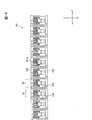
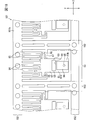
- the base material 151 has a pair of bridging leads 152 bridging the plurality of SA substrates 53 and a connecting lead 153 connecting the bridging leads 152.
- the lead terminals 64 and 65 are in a state of being connected to the bridging lead 152
- the circuit protection frame 67 is in a state of being connected to the connecting lead 153.
- the detection frame 61 and the connection frame 63 are connected to the bridge lead 152 via the ground lead terminal 64. Therefore, it is not necessary to provide a suspension lead for connecting the detection frame 61 and the connection frame 63 to the bridging lead 152 and the connecting lead 153 on the base 151.
- the SA substrate 53 at the stage when the base material 151 is molded is formed by the ground lead terminal 64 and the like from the detection frame 61 and the like. Become separated.
- a step of attaching the filter section 96 to the punched surface 151b of the base material 151 is performed.
- the filter portion 96 is attached to the back surface 53b of each of the SA substrates 53 on the base material 151.
- the filter unit 96 is attached to the back surface 61b of the detection frame 61 using an adhesive or the like so that the filter unit 96 is positioned to cover the detection frame hole 95. Since the filter portion 96 is attached to the punched surface 151b, the filter portion 96 is less likely to be damaged by burrs left on the punched surface 151a.
- the filter portion 96 in a configuration in which the filter portion 96 is attached to the punched surface 151a, the filter portion 96 is damaged by burrs left on the punched surface 151a, and the foreign matter removing performance of the filter portion 96 is reduced. Is concerned.
- a step of attaching chip components such as the flow rate detector 22 to the punched surface 151a of the base material 151 is performed.
- chip components such as the flow detection unit 22, the flow processing unit 54, and the protection chip 71 are mounted on each of the SA substrates 53 on the base material 151.
- the bonding wires 72 are connected to the flow detection unit 22, the flow processing unit 54, the circuit lead terminal 65, the circuit protection frame 67, and the like.
- the flow rate detection unit 22 when attaching the flow rate detection unit 22 to the punched surface 151a, there is a concern that the flow rate detection unit 22 may be damaged by burrs remaining on the punched surface 151a. Specifically, there is a concern that burrs remaining on the peripheral edge of the front opening 95 a of the detection frame 61 may contact the back surface 22 b of the flow rate detection unit 22.
- the front opening 95a is recessed so that the peripheral edge of the front opening 95a of the detection frame 61 is arranged at a position inwardly separated from the peripheral edge of the concave opening 91c of the flow rate detecting unit 22. It is sufficiently smaller than the opening 91c.
- the flow rate detection unit 22 is attached to the detection frame 61 so that the front opening 95a is arranged inside the periphery of the concave opening 91c. This can prevent the flow rate detector 22 from being damaged by burrs.
- a step of attaching the mold section 55 to the base material 151 is performed.
- This step can be referred to as a molding step of molding the mold section 55.
- a molding unit is provided on each of the SA substrates 53 on the base material 151 so as to cover the flow detection unit 22, the flow processing unit 54, the protection chip 71, the bonding wires 72, and the filter unit 96. 55 is attached.
- the mold device 160 is mounted on each SA substrate 53 of the base material 151, and the mold unit 55 is resin-molded by the mold device 160.
- the mold apparatus 160 has a front mold part 161 for molding the front cover part 84 of the mold part 55, and a back mold part 165 for molding the back cover part 85 of the mold part 55. are doing.
- the front mold portion 161 forms the front surface 55e of the mold portion 55. It has a surface concave portion 161a.
- the back mold part 165 has a back mold recess 165a for molding the back surface 55f of the mold part 55.
- the front mold part 161 has a groove molding part 162 for molding the front mold groove 88 in the mold part 55.
- the groove forming portion 162 is a protruding portion that protrudes so that the bottom surface of the front concave portion 161a swells.
- the groove forming portion 162 gradually becomes thinner toward the front end surface 162a, and has a tapered shape as a whole.
- the tip end surface 162a of the groove forming portion 162 presses the front extension region 22X of the flow rate detection portion 22.
- the groove molding portion 162 is a portion that exposes the membrane portion 92 and the surface extension region 22X by coming into contact with the surface extension region 22X, and corresponds to the surface exposure molding portion.
- the groove forming section 162 is provided with an avoiding recess 163 for preventing the groove forming section 162 from coming into contact with the membrane section 92 when the mold device 160 is mounted on the SA substrate 53.
- the avoiding recess 163 is formed by recessing the tip end surface 162 a of the groove forming portion 162, and the open end of the avoiding recess 163 is larger than the membrane 92.
- the tip end surface 162a of the groove forming portion 162 has an annular shape by making one round along the periphery of the avoidance concave portion 163.
- the back mold part 165 has a hole forming part 166 for forming the back mold hole 87 in the mold part 55.
- the hole forming portion 166 is a protruding portion that protrudes so that the bottom surface of the back mold concave portion 165a swells.
- the hole forming portion 166 is gradually tapered toward its distal end surface 166a, and is tapered as a whole.
- the tip end surface 166a of the hole forming portion 166 presses the back extension region 61X via the filter portion 96.
- the hole forming part 166 is a part that comes into contact with the filter part 96 to expose the detection frame hole 95 and the back extension area 61X through the filter part 96, and corresponds to a back exposed part.
- the tip end surface 166a of the hole forming part 166 is in contact with a part of the filter part 96 that overlaps the back extension area 61X of the detection frame 61.
- this state is also referred to as a state in which the distal end surface 166a of the hole forming section 166 is in contact with the back extension area 61X via the filter section 96.
- the mold apparatus 160 is assembled such that the SA substrate 53 of the base material 151 is sandwiched between the front mold section 161 and the back mold section 165, and the mold apparatus 160 is fixed to the base material 151 by clamping. Attach. Then, the molten resin is injected and filled into the internal space of the mold device 160 from an injection port formed in the mold device 160.
- the internal space of the mold device 160 is formed by each internal space of the front mold concave portion 161a and the back mold concave portion 165a.
- the mold device 160 has a plurality of front mold concave portions 161a and a back mold concave portion 165a, so that the mold device 160 can mold a plurality of mold portions 55.
- the front end surface 162a of the groove forming portion 162 of the front mold portion 161 overlaps the front extension region 22X, and the front end surface 166a of the hole forming portion 166 of the back mold portion 165 is connected. It overlaps with the back extension area 61X via the filter part 96.
- the groove forming section 162 and the hole forming section 166 press the flow rate detection section 22 and the detection frame 61 in a direction approaching each other. Therefore, when the molten resin is injected into the mold device 160, it is possible to restrict the molten resin from entering an unintended portion.
- the avoidance concave portion 163 is formed in the front end surface 162a of the groove forming portion 162, even when the groove forming portion 162 is pressed against the front extension region 22X, the front end surface 162a does not contact the membrane portion 92. It has become. For this reason, it is difficult for the membrane part 92 to be deformed by being pressed by the groove forming part 162.
- the front end surface 162 a of the groove forming portion 162 of the front mold portion 161 has an annular shape so as to surround the avoidance concave portion 163. Therefore, the molten resin does not enter the avoidance recess 163 through the space between the front end surface 162a of the groove forming portion 162 and the back extension region 61X.
- each of the front extension region 22X and the back extension region 61X is a region as large as possible, the front extension region 22X and the back extension region 61X are added to the front extension region 22X and the back extension region 61X from the groove molding portion 162 and the hole molding portion 166.
- the pressure is easily dispersed in these extension regions 22X and 61X. For example, as the surface extension region 22X is smaller, the pressure applied from the groove forming portion 162 to the surface extension region 22X becomes more difficult to disperse, and there is a concern that the flow rate detector 22 may be deformed or damaged.
- the pressure applied from the hole forming section 166 to the back extension area 61X becomes more difficult to disperse, and there is a concern that the detection frame 61 and the filter section 96 may be deformed or damaged. You.
- the groove forming part 162 is movable in the width direction X with respect to other parts, and the pressure with which the groove forming part 162 is pressed against the front extension region 22 ⁇ / b> X is adjustable. It has become. Therefore, after restricting the infiltration of the molten resin between the front end surface 162a of the groove forming portion 162 and the front extension region 22X, the flow rate detecting portion 22 is deformed or damaged by the pressure from the groove forming portion 162.
- the groove forming portion 162 can be pressed against the front extension region 22X with a pressure that does not make the groove extend.
- the mold device 160 is attached to the base 151 in a state where a mold filter formed of a fluororesin or the like is attached to the inner peripheral surface of the front mold concave portion 161a. With this mold filter, it is possible to suppress that the pressure applied from the groove forming portion 162 to the front extension region 22X and the pressure applied from the hole molding portion 166 to the back extension region 61X vary from product to product.
- the mold device 160 is disassembled to remove the front mold portion 161 and the back mold portion 165 from the base material 151 and the mold portion 55. Then, as shown in FIG. 22, the plurality of sensors SA50 are connected to each other by the bridging lead 152 and the connecting lead 153 on the base material 151.
- a step of removing the sensor SA50 from the leads 152 and 153 is performed.
- a tie bar cut is performed.
- the lead terminals 64 and 65 are separated from the bridge lead 152, and the circuit protection frame 67 is connected and separated from the lead 153.
- the cut surface of the circuit protection frame 67 is exposed to the side of the sensor SA50 on the mold downstream surface 55d.
- the cut surface of the circuit protection frame 67 may be coated with a resin or the like.
- the sensor SA50 is installed in the internal space 24a of the molded housing 21. Then, the lead terminals 64 and 65 of the sensor SA50 are connected to the connector terminal 28a. In this case, the back surfaces of the lead terminals 64 and 65 are brought into contact with the connector terminal 28a. As described above, the back surfaces of the lead terminals 64 and 65 are formed by the punched surface 151b of the base material 151. For this reason, even if burrs remain on the periphery of the lead terminals 64 and 65 on the punched surface 151a, it is difficult for the burrs to contact the connector terminal 28a. In this case, it is possible to suppress the occurrence of poor contact between the lead terminals 64 and 65 and the connector terminal 28a due to burrs being sandwiched between the lead terminals 64 and 65 and the connector terminal 28a.
- the front opening 95a of the detection frame hole 95 is disposed at a position spaced inward from the peripheral edge of the concave opening 91c of the detection concave portion 91 in the flow rate detecting section 22. For this reason, even if burrs remain on the periphery of the front opening 95 a in the detection frame 61, these burrs are hard to come into contact with the flow rate detection unit 22 by being arranged inside the front opening 95 a. .
- the detection concave portion 91 is opened to the outside via the detection frame hole 95, it is possible to prevent the membrane portion 92 from being deformed due to the pressure difference and the detection accuracy of the flow rate detection portion 22 from being reduced. Therefore, after the detection accuracy of the flow rate detection unit 22 is increased by the detection frame hole 95, it is possible to prevent the burr from contacting the flow rate detection unit 22 and prevent the flow rate detection unit 22 from being damaged by the burr.
- the front opening 95 a of the detection frame 61 is disposed at a position inwardly separated from both the periphery of the concave opening 91 c of the detection recess 91 and the periphery of the membrane 92.
- the burr extending from the peripheral portion of the front opening 95a is arranged on the inner peripheral side of the inner wall surface 91b. . Therefore, it is possible to prevent the inner wall surface 91b of the detection concave portion 91 from being damaged or damaged by burrs.
- the flow rate detection unit 22 that has taken a countermeasure against burrs that the concave opening 91c is larger than the front opening 95a is attached to the surface 61a of the detection frame 61 where burrs are likely to occur.
- the filter portion 96 on which no burrs are taken is attached to the back surface 61b where burrs are less likely to occur. Therefore, even when only the flow detection unit 22 of the flow detection unit 22 and the filter unit 96 is provided with a burr countermeasure, it is possible to prevent the filter unit 96 from being damaged by burrs.
- the inner diameter L3 of the front opening 95a of the detection frame hole 95 is larger than the thickness D1 of the detection frame 61. In this case, it is suppressed that the front opening 95a is too small with respect to the thickness of the detection frame 61, so that the pressure loss in the detection frame hole 95 becomes large and it becomes difficult to ventilate the detection recess 91 through the detection frame hole 95. it can.
- the front extension region 22X of the flow rate detection unit 22 and the back extension region 61X of the detection frame 61 are arranged in the width direction X. For this reason, when resin molding is performed on the mold portion 55 using the mold device 160, the front mold portion 161 presses the front extension region 22X, and the back mold portion 165 presses the back extension region 61X, thereby reducing the flow rate.
- the back surface 22b of the detection unit 22 and the front surface 61a of the detection frame 61 can be brought into close contact. In this case, it is possible to prevent the molten resin filled in the mold device 160 from entering an unintended portion such as between the flow rate detection unit 22 and the detection frame 61.
- the back mold hole 87 gradually decreases in the width direction X toward the detection frame 61.
- the air flowing along the back surface 55f of the mold portion 55 reaches the detection frame hole 95 by gradually changing its direction along the inner peripheral surface 87b of the back mold hole 87. For this reason, turbulence of the air flow is less likely to occur around the back mold hole 87, and air can easily enter and exit the detection recess 91 through the back mold hole 87 and the detection frame hole 95.
- the hole molding portion 166 that molds the inner peripheral surface 87b of the back mold hole 87 in the back mold portion 165 gradually becomes thinner toward the tip surface 166a. For this reason, when removing the back mold part 165 from the mold part 55 after the molten resin has hardened, the hole molding part 166 can be easily removed from the back mold hole 87. In this case, when removing the hole forming portion 166 from the back mold hole 87, the hole forming portion 166 is in close contact with the inner peripheral surface of the back mold hole 87, so that the hole forming portion 166 pulls the back cover portion 85 to the back side. Becomes less likely to occur.
- the back mold part 165 when the back mold part 165 is removed from the mold part 55, it is difficult for the back cover part 85 to be pulled to the back side and the filter part 96, the detection frame 61, and the flow rate detection part 22 to be deformed.
- the stress applied to the flow detection unit 22 when the back mold 165 is removed from the mold unit 55 is reduced, the flow detection unit 22 is deformed with the removal of the back mold 165 and the flow detection unit 22 is deformed. It is possible to suppress a decrease in the detection accuracy of.
- the flow rate detection unit 22 is attached to the punched surface 151a on which burrs are likely to occur on the base material 151, and the filter unit 96 is attached to the punched surface 151b on which burrs are less likely to occur.
- the filter unit 96 is attached to the punched surface 151b on which burrs are less likely to occur.
- the back cover portion 85 is formed so as to cover the periphery of the filter portion 96 when the mold portion 55 is formed. Therefore, the separation of the filter portion 96 from the back surface 61b of the detection frame 61 can be regulated by the back cover portion 85.
- the configuration for controlling the separation of the filter portion 96 can be realized by performing the molding process of the mold portion 55, it is not necessary to perform a dedicated process for controlling the separation of the filter portion 96. For this reason, a configuration for controlling the separation of the filter portion 96 can be realized at low cost.
- the groove molding portion 162 of the front mold portion 161 and the hole molding portion 166 of the back mold portion 165 sandwich the flow rate detection unit 22 and the detection frame 61. become. Therefore, it is possible to suppress the molten resin from entering an unintended portion such as between the flow rate detection unit 22 and the detection frame 61.
- the cross-sectional area of the detection concave portion 91 gradually increases from the bottom surface 91a toward the concave opening 91c in the width direction X.
- the cross-sectional area of the detection concave portion 91 is reduced. It does not gradually increase toward 91c.
- the cross-sectional area of the detection concave portion 91 is made uniform in the width direction X.
- the inner wall surface 91b of the detection concave portion 91 extends from the bottom surface 91a toward the concave opening 91c in parallel with the center line CL.
- the area of the bottom surface 91a and the open area of the concave opening 91c are the same.
- the thickness of the base material hole 101a forming the detection recess 91 is uniform in the width direction X.
- the front opening 95a of the detection frame hole 95 is separated from the concave opening 91c of the detection concave portion 91 and the inner periphery of each of the peripheral portions of the bottom surface 91a.
- the base material hole 101a is formed by processing a part of the detection base material 101 by dry etching in the flow rate detection unit 22. That is, the detection concave portion 91 and the membrane portion 92 are formed by dry etching. In this case, in the detection concave portion 91, the concave opening 91c is not larger than the membrane portion 92. Even if the concave opening 91c is larger than the membrane 92, the concave opening 91c is only slightly larger than the membrane 92.
- the concave opening 91c of the detection concave portion 91 has substantially the same size as the membrane portion 92. For this reason, for example, as compared with the configuration in which the concave opening 91c is larger than the membrane part 92 as in the first embodiment, the back extension region 61X on the back surface 22b of the flow rate detecting unit 22 is reduced by the reduced concave opening 91c. growing. In this case, when molding the mold portion 55 using the mold device 160, the area where the hole forming portion 166 of the back mold portion 165 comes into contact with the back surface 22b of the flow rate detecting portion 22 becomes large. The pressure applied from the surface 166a to the back extension region 61X is easily dispersed. As described above, the pressing area of the flow molding section 166 by the hole molding section 166 increases the deformation area and the damage of the flow detection section 22 due to the pressing of the hole molding section 166.
- the peripheral portion of the filter portion 96 is covered by the mold portion 55, but in the third embodiment, the peripheral portion of the filter portion 96 is not covered by the mold portion 55. That is, in the first embodiment, the peripheral portion of the filter portion 96 is not exposed on the back side of the sensor SA50. However, in the third embodiment, the entirety including the peripheral portion of the filter portion 96 is exposed on the back side of the sensor SA50. are doing. In the present embodiment, a description will be given focusing on differences from the first embodiment.
- the filter section 96 is smaller than the outer peripheral end of the back extension area 61X of the detection frame 61.
- the filter portion 96 is smaller than the back mold hole 87, and the periphery of the filter portion 96 is separated from the periphery of the front end 87 a of the back mold hole 87 toward the inner periphery.
- the front opening 95 a and the back opening 95 b of the detection frame hole 95 have the same size and shape, and both the front opening 95 a and the back opening 95 b correspond to the recessed opening 91 c of the detection recess 91. It is separated from the inner peripheral surface to the inner peripheral side.
- the filter 96 may be in contact with the inner peripheral surface 87b of the back mold hole 87 as long as the filter 96 only covers the detection frame hole 95.
- the mold part 55 is molded after the filter part 96 is attached to the detection frame 61.
- the filter part 96 is molded after the mold part 55 is molded. Attach it to the detection frame 61.
- the tip end surface 166a of the hole molding part 166 in the back mold part 165 does not pass through the filter part 96 and the rear extension area of the detection frame 61. 61X will be in direct contact.
- the filter portion 96 is extended rearward of the detection frame 61 at a position separated from the inner peripheral surface 87b of the back mold hole 87 toward the inner peripheral side. It is attached to the area 61X with an adhesive or the like.
- the filter section 96 is attached to the detection frame 61 after the molding section 55 is molded. Therefore, for example, unlike the configuration in which the molding unit 55 is molded after the filter unit 96 is attached to the detection frame 61, the filter unit 96 is displaced with respect to the detection frame 61 or peels off as the molding unit 55 is molded. Does not occur.
- the back opening 95b of the detection frame hole 95 is separated from the peripheral edge of the concave opening 91c of the detection concave portion 91 toward the inner peripheral side.
- the back extension region 61X is larger by the smaller back opening 95b.
- the bonding area of the portion 96 can be increased.
- the filter portion 96 can be firmly adhered to the back surface of the detection frame 61, the filter portion 96 can be separated from the detection frame 61 even if the peripheral portion of the filter portion 96 is not covered with the mold portion 55. Peeling can be suppressed.
- the front opening 95 a of the detection frame hole 95 may be smaller than the concave opening 91 c of the detection concave portion 91, but larger than the membrane portion 92.
- the inner wall surface 91b of the detection concave portion 91 is curved so as to expand toward the outer peripheral side, it is possible to suppress the burr remaining on the peripheral portion of the front opening 95a from contacting the inner wall surface 91b.
- the thickness of the detection frame hole 95 may not be uniform.
- the configuration is such that the inner peripheral surface of the detection frame hole 95 is inclined with respect to the center line CL.
- the detection frame hole 95 may not be a round hole.
- the cross-sectional shape of the detection frame hole 95 is rectangular or elliptical.
- the separation distance of the portion where the separation distance is the smallest among the portions facing each other across the center line CL in the peripheral portion of the front opening 95a is the same as the detection frame 61. It is preferable that the thickness is larger than the thickness D1.
- the distance between a pair of sides facing each other in the front opening 95a is preferably larger than the thickness dimension D1 of the detection frame 61.
- the thickness of the SA substrate 53 may be non-uniform. Also in this case, it is preferable that the inner diameter L3 of the front opening 95a of the detection frame hole 95 is larger than the thickness dimension of the portion where the detection frame hole 95 is formed in the detection frame 61. Thereby, it can be suppressed that it is difficult to form the detection frame hole 95 in the detection frame 61 due to the front opening 95a being too small.
- the back mold hole 87 may not be gradually reduced in the width direction X toward the detection frame 61.
- the back mold hole 87 is configured to have a uniform thickness in any part in the width direction X.
- the back mold hole 87 may not be a round hole.
- the front end portion 87a of the back mold hole 87 has a rectangular or elliptical shape.
- the front mold groove 88 is formed in the mold portion 55, but since the hole penetrating the front cover portion 84 is formed, the membrane portion 92 of the flow rate detection portion 22 is formed.
- the front extension region 22X may be exposed on the front side of the sensor SA50.
- the back mold hole 87 is formed in the back cover part 85, but a groove communicating with the back opening 95 b of the detection frame hole 95 may be formed in the mold part 55.
- the front surface 61a of the detection frame 61 may be exposed on the front side of the sensor SA50 instead of or in addition to the back surface 61b of the detection frame 61. In this case, even if heat is transmitted from the processing frame 62 to the detection frame 61, the heat can be released to the outside from the surface 61a of the detection frame 61.
- the SA substrate 53 to which the flow rate detection unit 22 is attached may be configured to include an insulating plate material such as a glass plate.
- the detection frame 61 is formed to include a glass plate on the SA substrate 53.
- the filter section 96 may not be provided on the back surface 61b of the detection frame 61. Further, the filter section 96 may be provided between the flow rate detection section 22 and the detection frame 61. Even in this case, if the filter portion 96 covers the detection concave portion 91 from the back side, entry of foreign matter into the detection concave portion 91 can be suppressed by the filter portion 96.
- the back extension region 61X may not be provided on the back surface 61b of the detection frame 61.
- the peripheral edge of the front side end 87a of the back mold hole 87 which is the inner peripheral end of the back cover 85, overlaps the peripheral edge of the back opening 95b of the detection frame hole 95.
- the back mold portion 165 does not contact the back surface 61b of the detection frame 61 around the detection frame hole 95 when the mold portion 55 is molded.
- the front extension region 22X may not be provided on the surface 22a of the flow rate detection unit 22.
- the inner peripheral edge of the front cover 84 is configured to overlap the peripheral edge of the membrane 92. With this configuration, when molding the mold section 55, the front mold section 161 does not contact the surface 22 a of the flow rate detection section 22 around the membrane section 92.
- the sensor SA50 may include a physical quantity detection unit that detects a physical quantity different from the flow rate for a fluid such as intake air.
- the physical quantity detection unit include a detection unit that detects temperature, a detection unit that detects humidity, and a detection unit that detects pressure. These detectors may be provided in the measurement flow path 32 and the passage flow path 31 inside the housing 21, or may be provided in the intake path 12 outside the housing 21.
- the sensor SA50 has a physical quantity processing unit to which a detection result of the physical quantity detected by the physical quantity detection unit is input.
Landscapes
- Physics & Mathematics (AREA)
- Fluid Mechanics (AREA)
- General Physics & Mathematics (AREA)
- Engineering & Computer Science (AREA)
- Chemical & Material Sciences (AREA)
- Measuring Volume Flow (AREA)
- Analytical Chemistry (AREA)
- Combustion & Propulsion (AREA)
- Mechanical Engineering (AREA)
- General Engineering & Computer Science (AREA)
Abstract
物理量計測装置は、流体が流れる計測流路(32)と、計測流路において流体の物理量を検出する物理量検出部(22)と、物理量検出部の一面である裏面(22b)に重ねられ物理量検出部を支持する支持板部(53)と、を備える。物理量検出部は、その裏面に凹部(91)と、凹部の底面(91a)を形成し、流体の物理量を検出するための検出素子(121,122,131,132,133,134)が設けられたメンブレン部(92)と、を有する。支持板部において凹部を覆った部分(61)は、凹部に連通する連通孔(95)を有する。連通孔において凹部側の端部である孔開口(95a)の周縁部が、凹部において支持板部側の端部である凹開口(91c)の周縁部から内側に離間している。
Description
本出願は、2018年9月6日に出願された日本出願番号2018-167181号に基づくもので、ここにその記載内容を援用する。
本開示は、物理量計測装置及び物理量計測装置の製造方法に関する。
流体の物理量を計測する物理量計測装置として、例えば特許文献1には、空気の流量を検出する流量検出素子と、流量検出素子が搭載された金属基板とを有する熱式流量計が開示されている。この流量検出素子には、薄肉化されたダイヤフラムの裏面側に空隙が形成されており、金属基板はその空隙の開口を覆うように流量検出素子の裏面に重ねられている。そして、空隙に通じる通気孔が金属基板に形成されていることで、ダイヤフラムの表面及び裏面に作用する気圧が同じになるようになっている。通気孔の周縁部は流量検出素子の裏面のうち空隙の周縁部に重ねられている。
ここで、打ち抜き加工等により金属基板に通気孔を形成した場合に、通気孔の周縁部に不要な突起であるバリが残ることがある。金属基板において通気孔の周縁部が流量検出素子の裏面に重ねられた上記特許文献1の構成では、通気孔の周縁部に残ったバリが流量検出素子の裏面に接触することが懸念される。バリが流量検出素子に接触すると流量検出素子が破損することが考えられる。
本開示の主な目的は、物理量検出部を支持する支持板部に連通孔を形成することで物理量検出部の検出精度を高めた上で、連通孔の形成に伴って支持板部にバリが発生したとしてもこのバリが物理量検出部に接触することを抑制できる、物理量計測装置及び物理量計測装置の製造方法を提供することにある。
本開示の第1の態様によれば、流体の物理量を計測する物理量計測装置は、流体が流れる計測流路と、計測流路において流体の物理量を検出する物理量検出部と、物理量検出部の一面である裏面に重ねられた状態で物理量検出部を支持する支持板部と、を備える。物理量検出部は、物理量検出部の裏面が凹むことで形成された凹部と、物理量検出部において凹部の底面を形成し、流体の物理量を検出するための検出素子が設けられたメンブレン部と、を有する。支持板部において凹部を覆った部分には、支持板部を貫通していることで凹部に通じている連通孔が設けられており、連通孔において凹部側の端部である孔開口の周縁部が、凹部において支持板部側の端部である凹開口の周縁部から内側に離間している。
第1の態様によれば、支持板部に設けられた孔開口の周縁部が物理量検出部に設けられた凹開口の周縁部から内側に離間している。この場合、仮に、物理量計測装置の製造時において支持板部に連通孔を形成した際に連通孔の周縁部にバリが発生したとしても、このバリが凹開口の周縁部から内側に離間した位置に存在することになる。このため、バリが物理量検出部の裏面に接触するということを回避できる。また、支持板部に連通孔が形成されていることで、凹部の内部と外部との間に圧力差が生じにくくなっているため、凹部の内部と外部との圧力差によりメンブレン部が変形して物理量検出部の検出精度が低下するということを抑制できる。したがって、支持板部に連通孔を形成することで物理量検出部の検出精度を高めた上で、バリが物理量検出部に接触することを抑制できる。この結果、物理量検出部がバリとの接触により破損するということが生じにくくなる。
本開示の第2の態様によれば、流体の物理量を計測する物理量計測装置を製造する製造方法は、流体が流れる計測流路において流体の物理量を検出する板状の物理量検出部を、物理量検出部の一面である裏面が凹むことで形成された凹部と、流体の物理量を検出するための検出素子が設けられ物理量検出部において凹部の底面を形成するメンブレン部と、を有するように形成することと、物理量検出部を支持する支持板部において物理量検出部とは反対側の板面である裏板面から支持板部を打ち抜くことで、支持板部を貫通する連通孔を形成することと、連通孔において凹部側の端部である孔開口の周縁部を、凹部において支持板部側の端部である凹開口の周縁部から内側に離間させた状態で、連通孔が凹部に連通するように、支持板部における裏板面とは反対側の板面である表板面に物理量検出部を取り付けることと、を備える。
第2の態様によれば、支持板部をその裏面から打ち抜くことで連通孔が形成されているため、支持板部の打ち抜きに伴って発生したバリが支持板部の表面側において連通孔の周縁部に残っていることが懸念される。これに対して、支持板部に設けられた孔開口の周縁部が物理量検出部に設けられた凹開口の周縁部から内側に離間するように、支持板部の表面に物理量検出部が取り付けられる。このため、仮に支持板部の表面側において連通孔の周縁部にバリが残っていたとしても、このバリが凹開口の周縁部から内側に離間した位置に存在することになる。したがって、上記第1の態様と同様の効果を奏することができる。
以下、本開示の複数の実施形態を図面に基づいて説明する。尚、各実施形態において対応する構成要素には同一の符号を付すことにより、重複する説明を省略する場合がある。各実施形態において構成の一部分のみを説明している場合、当該構成の他の部分については、先行して説明した他の実施例の構成を適用することができる。また、各実施形態の説明において明示している構成の組み合わせばかりではなく、特に組み合わせに支障が生じなければ、明示していなくても複数の実施形態の構成同士を部分的に組み合わせることができる。そして、複数の実施形態及び変形例に記述された構成同士の明示されていない組み合わせも、以下の説明によって開示されているものとする。
(第1実施形態)
図1に示す燃焼システム10は、ガソリンエンジン等の内燃機関11、吸気通路12、排気通路13、エアフロメータ20及びECU15を有しており、例えば車両に搭載されている。エアフロメータ20は、吸気通路12に設けられており、内燃機関11に供給される吸入空気の流量や温度、湿度、圧力といった物理量を計測する。エアフロメータ20は、吸入空気等の流体を計測対象とした物理量計測装置に相当する。吸入空気は、内燃機関11の燃焼室11aに供給される気体である。燃焼室11aにおいては、吸入空気と燃料との混合気が点火プラグ17により点火される。
図1に示す燃焼システム10は、ガソリンエンジン等の内燃機関11、吸気通路12、排気通路13、エアフロメータ20及びECU15を有しており、例えば車両に搭載されている。エアフロメータ20は、吸気通路12に設けられており、内燃機関11に供給される吸入空気の流量や温度、湿度、圧力といった物理量を計測する。エアフロメータ20は、吸入空気等の流体を計測対象とした物理量計測装置に相当する。吸入空気は、内燃機関11の燃焼室11aに供給される気体である。燃焼室11aにおいては、吸入空気と燃料との混合気が点火プラグ17により点火される。
ECU(Engine Control Unit)15は、燃焼システム10の動作制御を行う制御装置である。ECU15は、プロセッサ、RAM、ROM及びフラッシュメモリ等の記憶媒体、並びに入出力部を含むマイクロコンピュータと、電源回路等と、によって構成された演算処理回路である。ECU15には、エアフロメータ20から出力されるセンサ信号や、多数の車載センサから出力されるセンサ信号などが入力される。ECU15は、エアフロメータ20による計測結果を用いて、インジェクタ16の燃料噴射量やEGR量などについてエンジン制御を行う。ECU15は、内燃機関11の運転制御を行う制御装置であり、燃焼システム10をエンジン制御システムと称することもできる。また、ECU15は、外部装置に相当する。
燃焼システム10は、車載センサとして複数の計測部を有している。計測部としては、エアフロメータ20の他に、スロットルセンサ18aや吸気圧センサ18b、水温センサ18c、クランク角センサ18d、空燃比センサ18e、ノックセンサ18f、カム角センサ18gなどがある。これら計測部は、いずれもECU15に電気的に接続されており、ECU15に対して検出信号を出力する。エアフロメータ20は、吸気通路12において、スロットルセンサ18aが取り付けられたスロットルバルブの上流側に設けられている。
図3に示すように、エアフロメータ20は、吸気通路12を形成するダクト等の吸気管12aに取り付けられている。吸気管12aには、その外周部を貫通する貫通孔としてエアフロ挿入孔12bが設けられている。このエアフロ挿入孔12bには円環状の管フランジ12cが取り付けられており、この管フランジ12cは吸気管12aに含まれている。エアフロメータ20は、管フランジ12c及びエアフロ挿入孔12bに挿入されることで吸気通路12に入り込んだ状態になっており、この状態で吸気管12aや管フランジ12cに固定されている。
本実施形態では、エアフロメータ20について、幅方向X、高さ方向Y及び奥行き方向Zを定義しており、これら方向X,Y,Zは互いに直交している。エアフロメータ20は高さ方向Yに延びており、吸気通路12は奥行き方向Zに延びている。エアフロメータ20は、吸気通路12に入り込んだ入り込み部分20aと、吸気通路12に入り込まずに管フランジ12cから外部にはみ出したはみ出し部分20bとを有しており、これら入り込み部分20aとはみ出し部分20bとは高さ方向Yに並んでいる。エアフロメータ20においては、高さ方向Yに並んだ一対の端面20c,20dのうち、入り込み部分20aに含まれた方をエアフロ先端面20cと称し、はみ出し部分20bに含まれた方をエアフロ基端面20dと称する。なお、エアフロ先端面20c及びエアフロ基端面20dは高さ方向Yに直交している。また、管フランジ12cの先端面も高さ方向Yに直交している。
図2、図3に示すように、エアフロメータ20は、ハウジング21と、吸入空気の流量を検出する流量検出部22と、吸入空気の温度を検出する吸気温センサ(図示略)とを有している。ハウジング21は、例えば樹脂材料等により形成されている。エアフロメータ20においては、ハウジング21が吸気管12aに取り付けられていることで、流量検出部22が、吸気通路12を流れる吸入空気と接触可能な状態になる。ハウジング21は、ハウジング本体24、リング保持部25、フランジ部27及びコネクタ部28を有しており、リング保持部25に対してOリング26が取り付けられている。
ハウジング本体24は全体として筒状に形成され、ハウジング21においては、リング保持部25、フランジ部27及びコネクタ部28がハウジング本体24に一体的に設けられた状態になっている。リング保持部25は入り込み部分20aに含まれ、フランジ部27及びコネクタ部28ははみ出し部分20bに含まれている。
リング保持部25は、管フランジ12cの内部に設けられており、Oリング26を高さ方向Yに位置ずれしないように保持している。Oリング26は、管フランジ12cの内部において吸気通路12を密閉するシール部材であり、リング保持部25の外周面と管フランジ12cの内周面との両方に密着している。フランジ部27には、エアフロメータ20を吸気管12aに固定するネジ等の固定具を固定するネジ孔等の固定孔が形成されている。コネクタ部28は、流量検出部22に電気的に接続されたコネクタターミナル28aを保護する保護部である。
流量検出部22はハウジング本体24の内部空間24aに設けられており、吸気温センサはハウジング21の外側に設けられている。吸気温センサは、吸入空気の温度を感知する感温素子や、感温素子から延びたリード線、リード線に接続された吸気温ターミナルを有している。ハウジング21は、吸気温センサを支持する支持部を有しており、この支持部は、ハウジング21の外周側に設けられている。
ハウジング本体24は、吸気通路12を流れる吸入空気の一部が流れ込むバイパス流路30を形成している。バイパス流路30は、エアフロメータ20の入り込み部分20aに配置されている。バイパス流路30は、通過流路31及び計測流路32を有しており、これら通過流路31及び計測流路32は、ハウジング本体24の内部空間24aにより形成されている。なお、吸気通路12を主通路と称し、バイパス流路30を副通路と称することもできる。
通過流路31は、奥行き方向Zにハウジング本体24を貫通している。通過流路31は、その上流端部である流入口33と、下流端部である流出口34とを有している。計測流路32は、通過流路31の中間部分から分岐した分岐流路であり、この計測流路32に流量検出部22が設けられている。計測流路32は、その上流端部である計測入口35と、下流端部である計測出口36とを有している。通過流路31から計測流路32が分岐した部分はこれら通過流路31と計測流路32との境界部になっており、この境界部に計測入口35が含まれていることになる。なお、計測入口35が分岐入口に相当し、計測出口36が分岐出口に相当する。また、通過流路31と計測流路32との境界部を流路境界部と称することもできる。
流量検出部22は、ヒータ部を有する熱式の流量センサである。流量検出部22は、ヒータ部の発熱に伴って温度変化が生じた場合に、その温度変化に応じた検出信号を出力する。流量検出部22は直方体状のチップ部品であり、流量検出部22をセンサチップと称することもできる。なお、流量検出部22が、吸入空気の流量を流体の物理量として検出する物理量検出部に相当する。
エアフロメータ20は、流量検出部22を含んで構成されたセンササブアッセンブリを有しており、このセンササブアッセンブリをセンサSA50と称する。センサSA50はハウジング本体24の内部空間24aに収容されている。なお、センサSA50を検出ユニットや計測ユニット、センサパッケージと称することもできる。
センサSA50は、内部空間24aにおいて計測流路32に入り込んだ入り込み部分50aと、計測流路32に入り込まずに計測流路32からはみ出したはみ出し部分50bとを有している。入り込み部分50aとはみ出し部分50bとは高さ方向Yに並んでおり、流量検出部22は入り込み部分50aに含まれている。
図4~図7に示すように、センサSA50は、流量検出部22を搭載したSA基板53と、流量検出部22に電気的に接続された流量処理部54と、SA基板53、流量検出部22及び流量処理部54を覆っているモールド部55とを有している。流量処理部54には、流量検出部22の検出結果として検出信号が入力され、流量検出部22は物理量処理部に相当する。また、SA基板53が支持板部に相当し、モールド部55が物理量検出部及び物理量処理部を保護するボデーに相当する。SA基板をリードフレームと称することもできる。図7においては、センサSA50の内部構造を図示するためにモールド部55を仮想線で示している。
モールド部55は、全体として板状に形成されている。図3に示すように、モールド部55においては、高さ方向Yに並んだ一対の端面55a,55bのうち、入り込み部分50aに含まれた方をモールド先端面55aと称し、はみ出し部分50bに含まれた方をモールド基端面55bと称する。また、モールド先端面55a及びモールド基端面55bを挟んで設けられた一対の面のうち一方をモールド上流面55cと称し、他方をモールド下流面55dと称する。センサSA50は、モールド先端面55aがエアフロ先端面20c側に配置され、且つモールド上流面55cがモールド下流面55dよりも計測流路32の上流側に配置される向きで、内部空間24aに設置されている。
センサSA50のモールド上流面55cは、計測流路32においてモールド下流面55dよりも上流側に配置されている。計測流路32において流量検出部22が設けられた部分においては、空気の流れる向きが吸気通路12での空気の流れる向きとは反対になっている。このため、モールド上流面55cは、吸気通路12においてはモールド下流面55dよりも下流側に配置されていることになる。
図6、図7において、SA基板53は、金属材料等により全体として板状に形成されており、導電性を有する基板である。SA基板53の板面は、幅方向Xに直交しており、高さ方向Y及び奥行き方向Zに延びている。SA基板53は、流量検出部22を支持する検出フレーム61と、流量処理部54を支持する処理フレーム62と、これらフレーム61,62を接続する接続フレーム63と、コネクタターミナル28aに接続されるリードターミナル64,65とを有している。なお、検出フレーム61が検出支持部に相当し、処理フレーム62が処理支持部に相当し、接続フレーム63が接続支持部に相当する。また、検出フレーム61は、SA基板53において凹部を覆った部分に相当し、覆い部とも称する。
検出フレーム61及び処理フレーム62は、いずれも全体として矩形状に形成されており、それぞれの板面が幅方向Xに直交している。検出フレーム61は、処理フレーム62からモールド先端面55a側に離間した位置に設けられている。接続フレーム63は、高さ方向Yにおいて検出フレーム61と処理フレーム62との間に一対設けられており、各接続フレーム63は、いずれも検出フレーム61と処理フレーム62とにかけ渡された状態になっている。一対の接続フレーム63は、互いに離間した状態で奥行き方向Zに並べられている。
SA基板53には、このSA基板53を幅方向Xに貫通する貫通孔として基板孔69が形成されている。基板孔69は、高さ方向Yにおいて検出フレーム61と処理フレーム62との間に設けられており、これらフレーム61,62の離間部分を形成している。また、基板孔69は、奥行き方向Zにおいて一対の接続フレーム63の間に設けられており、これら接続フレーム63の離間部分を形成している。基板孔69は、高さ方向Yにおいて流量検出部22と流量処理部54との間に配置されている。SA基板53に基板孔69が設けられていることで、高さ方向Yに直交する方向の断面積について、一対の接続フレーム63の各断面積の合計が、検出フレーム61の断面積及び処理フレーム62の断面積のいずれよりも小さくなっている。このため、接続フレーム63は、検出フレーム61及び処理フレーム62のいずれよりも熱が伝わりにくくなっている。なお、基板孔69が貫通部に相当する。
図8に示すように、SA基板53においては、一方の板面に流量検出部22及び流量処理部54の両方が搭載されており、これら流量検出部22及び流量処理部54が搭載された方の板面を表面53aと称し、表面53aとは反対側の板面を裏面53bと称する。SA基板53の表面53aには検出フレーム61の表面61aが含まれ、SA基板53の裏面53bには検出フレーム61の裏面61bが含まれており、これら表面61aと裏面61bとは互に平行に延びている。なお、検出フレーム61については、表面61aが表板面に相当し、裏面61bが裏板面に相当する。
流量検出部22は板状に形成されており、この流量検出部22については、検出フレーム61とは反対側の板面を表面22aと称し、この表面22aとは反対側の板面を裏面22bと称する。これら表面22aと裏面22bとも互いに平行に延びている。センサSA50においては、流量検出部22の裏面22bが検出フレーム61の表面61aに重ねられている。
図6、図7の説明に戻り、奥行き方向Zにおいて、基板孔69の両側端は、それぞれ流量検出部22及び流量処理部54のいずれよりも外側にはみ出した位置に配置されている。この場合、一対の接続フレーム63は、流量検出部22と流量処理部54との間に挟まれた位置に配置されているのではなく、幅方向X及び奥行き方向Zのいずれについても、流量検出部22及び流量処理部54から側方にずれた位置に配置されている。
検出フレーム61、処理フレーム62及び基板孔69は高さ方向Yに並べられており、高さ方向Yに延びる仮想の軸線に、検出フレーム61、処理フレーム62及び基板孔69の中心線が一致している。奥行き方向Zにおいて、流量検出部22は検出フレーム61の中央位置に配置され、流量処理部54は処理フレーム62の中央位置に配置されている。
奥行き方向Zにおいて、検出フレーム61の幅寸法W1と処理フレーム62の幅寸法W2とは同じになっている。また、流量検出部22の幅寸法W3は流量処理部54の幅寸法W4より小さくなっており、基板孔69の幅寸法W5は、これら幅寸法W3,W4より大きくなっている。基板孔69の幅寸法W5は、一対の接続フレーム63の離間距離になっている。
高さ方向Yにおいて、基板孔69の長さ寸法H1は、検出フレーム61と処理フレーム62との間での熱の伝わりが生じにくい大きさになっている。検出フレーム61は、流量検出部22よりも基板孔69側にはみ出すように延びた検出延出部68aを有しており、処理フレーム62は、流量処理部54よりもフレーム61側にはみ出すように延びた処理延出部68bを有している。この場合、基板孔69の長さ寸法H1は、流量検出部22からの検出延出部68aの延出寸法H2、及び流量処理部54からの処理延出部68bの延出寸法H3のいずれよりも大きくなっている。また、基板孔69の長さ寸法H1は延出寸法H2,H3の和よりも大きくなっている。さらに、高さ方向Yにおいて、基板孔69は流量検出部22と流量処理部54との中央に配置されており、検出延出部68aの延出寸法H2と処理延出部68bの延出寸法H2とがほぼ同じ値になっている。
リードターミナル64,65は、それぞれの一部がモールド基端面55bからモールド部55の外部に突出している。リードターミナル64,65において、モールド部55の外部に突出した部分はモールド基端面55bから高さ方向Yに延びており、ハウジング本体24の内部空間24aにおいてコネクタターミナル28aに接続されている。この場合、SA基板53の裏面53bにはリードターミナル64,65の裏面が含まれており、リードターミナル64,65の裏面がコネクタターミナル28aに接触した状態になっている。
リードターミナル64,65のうち、グランドリードターミナル64は、処理フレーム62から延びており、センサSA50においてグランド端子に電気的に接続されている。この場合、検出フレーム61及び接続フレーム63も処理フレーム62を介して接地されている。なお、グランドリードターミナル64が支持ターミナルに相当する。
回路リードターミナル65は、モールド部55の内部において処理フレーム62から離間している一方で、流量処理部54に電気的に接続されている。グランドリードターミナル64及び回路リードターミナル65はそれぞれ複数設けられている。複数の回路リードターミナル65には、センサSA50において電源端子に電力を供給する電源ターミナルや、センサSA50において信号端子への信号の入出力を行う信号ターミナルが含まれている。
センサSA50は、ノイズから流量処理部54を保護する保護チップ71を有している。保護チップ71は、コンデンサを含んで構成された保護回路を有するチップ部品であり、モールド部55の内部においてグランドリードターミナル64と回路リードターミナル65とにかけ渡された状態で設けられている。
SA基板53は、保護チップ71が取り付けられた保護フレーム66,67を有している。保護フレーム66,67のうち、グランド保護フレーム66は、処理フレーム62から延びている。回路保護フレーム67は、モールド部55の内部において処理フレーム62から離間している一方で、流量処理部54に電気的に接続されている。保護チップ71は、グランド保護フレーム66と回路保護フレーム67又は回路リードターミナル65とにかけ渡された状態で設けられている。
流量処理部54は、各種処理を行うデジタル回路(図11参照)等の駆動回路を有している。流量処理部54は直方体状のチップ部品であり、流量処理部54を回路チップと称することもできる。流量検出部22、回路リードターミナル65及び回路保護フレーム67に、ボンディングワイヤ72を介して電気的に接続されている。モールド部55は、流量検出部22や流量処理部54に加えて、保護チップ71及びボンディングワイヤ72を覆っていることで、これら流量検出部22、流量処理部54、保護チップ71及びボンディングワイヤ72を保護している。この場合、モールド部55を保護体と称することもできる。
モールド部55は、モールド成型により成型された高分子樹脂等のモールド樹脂であり、SA基板53よりも高い絶縁性及び断熱性を有している。モールド部55は、流量処理部54や保護チップ71、ボンディングワイヤ72などを一体的に封止している。
図8に示すように、モールド部55は、処理フレーム62から検出フレーム61に熱が伝わることを規制するフレーム規制部81を有している。フレーム規制部81は、モールド部55のうち基板孔69に入り込んだ部分であり、基板孔69の内部に充填された状態になっている。このため、フレーム規制部81は、基板孔69と同じ大きさ及び形状になっている。例えば、奥行き方向Zにおいてフレーム規制部81の幅寸法は、基板孔69の幅寸法W5と同じになっている。フレーム規制部81は、奥行き方向Zにおいて接続フレーム63に横並びに配置されている。この場合、フレーム規制部81と接続フレーム63とは、SA基板53の板面に沿って横並びに配置されていることになる。なお、フレーム規制部81が伝熱規制部に相当する。
流量処理部54が通電に伴って各種処理を行った場合、流量処理部54にて熱が発生することがある。この熱が流量検出部22に伝わると、流量検出部22の検出精度が低下することが懸念される。特に、イグニッションスイッチがオンされた場合など電源投入時においては、流量処理部54の駆動開始に伴って流量処理部54が発熱を開始する。この場合、流量処理部54が熱を発生していなかった状態から熱を発生する状態に移行することになるため、流量処理部54の上昇温度が大きくなりやすい。このため、流量検出部22の温度が流量処理部54から伝わっている熱に応じた温度で安定するまでは、流量検出部22の検出値が不安定になりやすい。この結果、電源投入時においてエアフロメータ20の起動特定が悪く、電源が投入されてからしばらくの期間は流量検出部22の応答性が低下しやすくなってしまう。
これに対して、本実施形態では、上述したように、基板孔69の全体にフレーム規制部81が設けられているため、流量処理部54の熱がSA基板53を介して流量検出部22に伝わることがフレーム規制部81により規制されている。このため、エアフロメータ20の起動特性が悪くなることが抑制され、流量検出部22の応答性が低下しにくくなっている。また、モールド部55は、フレーム規制部81に加えて、高さ方向Yにおいて流量処理部54と流量検出部22との間に入り込んだ部分である直接規制部82を有している。直接規制部82は、SA基板53を介さずに流量処理部54から流量検出部22に直接的に熱が伝わることを規制する部分になっている。
図8~図10に示すように、流量検出部22は、その裏面22bが凹むことで形成された検出凹部91と、この検出凹部91の底面91aを形成しているメンブレン部92とを有している。検出凹部91は、検出フレーム61側を向いた底面91aと、この底面91aから検出フレーム61側に向けて延びた内壁面91bとを有している。検出凹部91は、この検出凹部91の内部空間を底面91aとは反対側に向けて開放する開口である凹開口91cを有しており、この凹開口91cは、流量検出部22の裏面22bに形成されている。検出凹部91は検出フレーム61により覆われており、底面91aは検出フレーム61の表面61aに対向している。なお、検出凹部91が凹部に相当する。また、検出凹部91の内部空間は空洞になっており、検出凹部91を空洞部や空隙部と称することもできる。
検出凹部91の中心線CLは、幅方向Xに延びており、流量検出部22の表面22a及び裏面22bに直交している。検出凹部91は、凹開口91cから底面91aに向けて先細りしており、内壁面91bが凹開口91cから底面91aに向けて真っ直ぐに延びていることで全体としてテーパ状に形成されている。検出凹部91の内部空間は、幅方向Xにおいて底面91aに向けて徐々に小さくなっており、検出凹部91は全体としてテーパ状になっている。この場合、検出凹部91においては、中心線CLに直交する方向の断面積が底面91aから凹開口91cに向けて徐々に大きくなっている。内壁面91bは、中心線CLに平行にはなっておらず、凹開口91c側を向いていることで中心線CLに対して傾斜している。検出凹部91は、互いに対向する一対の内壁面91bを2組有していることで、底面91a及び凹開口91cが矩形状に形成されている。検出凹部91においては、凹開口91cの開放面積が底面91aの面積より大きくなっている。
内壁面91bにおいては、裏面22b側の端部が凹開口91cの周縁部を形成しており、表面22a側の端部が底面91aの周縁部を形成している。図10に示すように、本実施形態では、凹開口91cの周縁部のうち互いに対向する一対の辺の離間距離を凹開口91cの開口寸法L1と称し、底面91aの周縁部のうち互いに対向する一対の辺の離間距離を底面寸法L2と称する。凹開口91c及び底面91aはいずれも正方形になっており、開口寸法L1及び底面寸法L2は、高さ方向Yに並ぶ一対の辺、及び奥行き方向Zに並ぶ一対の辺のいずれについても同じになっている。凹開口91cの開口寸法L1は、底面91aの底面寸法L2より大きくなっている。なお、図10においてはモールド部55の図示を省略し、メンブレン部92を実際より肉厚に図示している。
メンブレン部92は、幅方向Xにおいて検出凹部91の表側に設けられており、流量検出部22において検出凹部91により薄肉化された膜状の部位である。メンブレン部92の表面は流量検出部22の表面22aにより形成されており、裏面は検出凹部91の底面91aにより形成されている。この場合、メンブレン部92は、流量検出部22において表面22aと裏面22bとの間に配置されているのではなく、表面22aに配置されていることになる。メンブレン部92は、複数の検出素子を有しており、流量検出部22において空気の流量を検出するセンサ部になっている。
平面視においてメンブレン部92の形状及び大きさは、検出凹部91の形状及び大きさと同じになっている。具体的には、メンブレン部92の周縁部のうち互いに対向する一対の辺の離間距離をメンブレン寸法と称すると、このメンブレン寸法は底面寸法L2と同じになっている。また、メンブレン部92は、検出凹部91と同様に正方形になっており、メンブレン寸法は、高さ方向Yに並ぶ一対の辺、及び奥行き方向Zに並ぶ一対の辺のいずれについても同じになっている。
検出フレーム61において検出凹部91の凹開口91cを覆った部分には、検出凹部91の内部空間に通じる検出フレーム孔95が設けられている。検出フレーム孔95は、検出フレーム61を幅方向Xに貫通する貫通孔であり、断面円状の丸孔になっている。検出フレーム孔95の中心線は検出凹部91の中心線CLに一致している。検出フレーム孔95は、表面61a側の端部である表開口95aを有している。検出凹部91と検出フレーム孔95との境界部には、凹開口91c及び表開口95aが含まれている。なお、検出フレーム61が検出凹部91を覆った部分に相当し、検出フレーム孔95が連通孔に相当し、表開口95aが孔開口に相当する。
表開口95aの周縁部は、凹開口91cの周縁部から中心線CL側である内周側に離間した位置にある。この場合、表開口95aは凹開口91cよりも小さい開口になっている。具体的には、表開口95aの内径L3が凹開口91cの開口寸法L1より小さくなっている。表開口95aの内径L3は、表開口95aの周縁部において中心線CLを挟んで対向する部分のうち互いの離間距離が最も近い部分の離間距離に相当する。表開口95aの中心は、中心線CLが通っている部分になっている。また、検出フレーム孔95の太さは幅方向Xのどの部分においても均一になっており、検出フレーム孔95の内径は、表開口95aの内径L3と同じになっている。
また、表開口95aの周縁部は、検出凹部91の底面91aの周縁部から内周側に離間した位置にある。すなわち、表開口95aの周縁部は、メンブレン部92から内周側に離間した位置にある。この場合、表開口95aは底面91aよりも小さい開口になっている。具体的には、表開口95aの内径L3が底面91aの底面寸法L2より小さくなっている。
検出フレーム61に検出フレーム孔95を形成する場合、不要な突起であるバリが検出フレーム孔95の周縁部に残ることが想定される。例えば、打ち抜き加工やプレス加工により検出フレーム孔95を形成する場合に、検出フレーム61を裏面61bから表面61a側に向けて打ち抜くと、表面61aから延びたバリが表開口95aの周縁部に生じることが想定される。このバリが流量検出部22の裏面22bに接触すると、流量検出部22が傷付いたり破損したりして流量検出部22の検出精度が低下することが懸念される。これに対して、本実施形態では、表開口95aの周縁部が凹開口91cの周縁部よりも内側にあるため、表開口95aの周縁部にバリが残っていたとしても、このバリは凹開口91cの周縁部よりも内側に存在することになる。すなわち、バリが検出凹部91の内部空間に存在することになる。このため、このバリが流量検出部22の裏面22bに接触して流量検出部22が傷付いたり破損したりすることを抑制できる。
センサSA50は、検出フレーム孔95を裏面61b側から覆うフィルタ部96を有している。フィルタ部96は、空気を通過させることが可能な多孔質膜等の膜状の通気フィルタであり、検出フレーム61の裏面61bに重ねられている。フィルタ部96は、検出フレーム孔95や検出凹部91に流入する空気から砂塵やダスト、埃等の異物を除去する部材である。フィルタ部96は、検出フレーム61の裏面61bより小さくなっており、この裏面61bから外側にはみ出さない位置に配置されている。検出フレーム孔95は、裏面61b側の端部である裏開口95bを有しており、この裏開口95bは、検出フレーム孔95とフィルタ部96との境界部に含まれている。
図8、図9に示すように、モールド部55は、検出フレーム61の表面61a側に設けられた表覆い部84と、検出フレーム61の裏面61b側に設けられた裏覆い部85とを有している。表覆い部84は、流量検出部22のメンブレン部92をセンサSA50の表側に露出させた状態で、流量検出部22ごと検出フレーム61の表面61aを表側から覆っている。この場合、表覆い部84は、検出フレーム61の表面61a及び流量検出部22の表面22aのそれぞれに重ねられた状態になっている。なお、表覆い部84が検出ボデー部に相当する。
流量検出部22の表面22aは、メンブレン部92から外周側に向けて延びた表延出領域22Xを有している。表延出領域22Xは、流量検出部22の表面22aのうち、メンブレン部92の周囲においてセンサSA50の表側に露出した露出領域である。この場合、流量検出部22の表面22aは、その全体がセンサSA50の表側に露出しているのではく、この表面22aのうちメンブレン部92及び表延出領域22XだけがセンサSA50の表側に露出している。表延出領域22Xは、メンブレン部92と表覆い部84との間において、メンブレン部92の周縁部に沿って1周していることで環状になっている。
モールド部55においては、表覆い部84の一部が薄くなっていることで、メンブレン部92及び表延出領域22Xが表覆い部84により覆われていない状態になっている。具体的には、図4、図8に示すように、モールド部55には、奥行き方向Zに延びた溝状の表モールド溝88が設けられている。表モールド溝88は、モールド部55の表面が凹むことで形成された溝であり、モールド上流面55cとモールド下流面55dとにかけ渡されている。表モールド溝88の深さ寸法は、流量検出部22の表面22aが露出する一方で、検出フレーム61の表面61aが露出しない値になっており、表モールド溝88の底面88aには、流量検出部22の表面22aが含まれている。すなわち、メンブレン部92及び表延出領域22Xは、表モールド溝88の底面88aに露出している。
表モールド溝88の内部空間は、幅方向Xにおいて底面88aに向けて徐々に小さくなっている。表モールド溝88の内周面は、底面88aを挟んで対向する一対の内壁面88bを有している。これら内壁面88bは、流量検出部22とは反対側を向くように幅方向Xに対して傾斜しており、底面88aから真っ直ぐに延びたテーパ面になっている。表延出領域22Xは、一対の内壁面88bにかけ渡された状態になっている。
表モールド溝88においては、流量検出部22が奥行き方向Zの中間位置に設けられている。すなわち、流量検出部22は、モールド上流面55cとモールド下流面55dとの間に設けられている。また、表モールド溝88が計測流路32での空気の流れ方向に延びるように、センサSA50が計測流路32に対して設置されている。したがって、計測流路32を流れる空気は、流量検出部22に到達するまでに表モールド溝88の内周面により整流されることになる。このため、流量検出部22の検出精度が気流の乱れにより低下するということを抑制できる。
裏覆い部85は、フィルタ部96の一部をセンサSA50の裏側に露出させた状態で、フィルタ部96ごと検出フレーム61の裏面61bを裏側から覆っている。この場合、裏覆い部85は、検出フレーム61の裏面61b及びフィルタ部96の裏面のそれぞれに重ねられた状態になっている。フィルタ部96においてセンサSA50の裏側に露出した部分には、検出フレーム孔95の裏開口95bに重なった部分が含まれており、この検出フレーム孔95は、フィルタ部96を介してセンサSA50の裏側に開放されている。なお、裏覆い部85が支持ボデー部に相当する。
本実施形態では、検出フレーム孔95がフィルタ部96により覆われていても裏覆い部85により覆われていなければ、この状態を「検出フレーム孔95が露出した状態」と称する。これは、後述する裏延出領域61Xについても同様であり、裏延出領域61Xがフィルタ部96により覆われていても裏覆い部85により覆われていなければ、この状態を「裏延出領域61Xが露出した状態」と称する。
検出フレーム61の裏面61bは、裏開口95bから外周側に向けて延びた裏延出領域61Xを有している。裏延出領域61Xは、検出フレーム61の裏面61bのうち、検出フレーム孔95の裏開口95bの周囲においてセンサSA50の裏側に露出した露出領域である。この場合、検出フレーム61の裏面61bは、その全体がセンサSA50の裏側に露出しているのではなく、この裏面61bのうち検出フレーム孔95及び裏延出領域61XだけがセンサSA50の裏面に露出している。裏延出領域61Xは、検出フレーム孔95の裏開口95bと裏覆い部85との間において、裏開口95bの周縁部に沿って1周していることで環状になっている。
図5、図8に示すように、モールド部55においては、裏覆い部85に裏モールド孔87が設けられていることで、検出フレーム孔95及び裏延出領域61Xが裏覆い部85により覆われていない状態になっている。裏モールド孔87は、裏覆い部85を幅方向Xに貫通しており、検出フレーム孔95及びよりも大きい丸孔になっている。裏モールド孔87は、検出フレーム61側の端部である表側端部87aを有しており、この表側端部87aの周縁部は検出フレーム孔95の裏開口95bから外周側に離間している。これにより、表側端部87aの周縁部と裏開口95bとの間に裏延出領域61Xが形成されている。この場合、表側端部87aの内径L4は、裏開口95bの内径より大きくなっている。検出フレーム孔95においては、裏開口95bの内径が表開口95aの内径L3と同じになっている。なお、裏モールド孔87は、検出フレーム孔95及び裏延出領域61Xを露出させる露出孔と、検出フレーム61の熱を外部に放出する放熱孔とに相当する。
また、表側端部87aの周縁部は、検出凹部91の底面91a及び凹開口91cのいずれからも外周側に離間している。この場合、表側端部87aの内径L4は、底面91aの底面寸法L2(図10参照)及び凹開口91cの開口寸法L1(図10参照)のいずれよりも大きくなっている。
流量検出部22の表延出領域22Xと検出フレーム61の裏延出領域61Xとは幅方向Xに並んでいる。この場合、表延出領域22Xと裏延出領域61Xとは、互いの少なくとも一部が幅方向Xに重複しており、この重複部分は、中心線CLの周りを1周していることで環状になっている。
裏モールド孔87は検出フレーム61及びフィルタ部96のいずれよりも小さくなっている。モールド部55は、検出フレーム61及びフィルタ部96の周縁部を覆っている。この場合、フィルタ部96が検出フレーム61から剥がれることがモールド部55により規制されている。
裏モールド孔87は、幅方向Xにおいて検出フレーム61に向けて徐々に小さくなっている。すなわち、裏モールド孔87は、表側端部87aから裏側端部に向けて徐々に大きくなっている。裏モールド孔87の内周面87bは、検出フレーム61とは反対側を向くように幅方向Xに対して傾斜しており、表側端部87aから真っ直ぐに延びたテーパ面になっている。
図10に示すように、流量検出部22は、板状の母材である検出母材101と、絶縁性を有する絶縁膜102と、複数の抵抗素子を有する抵抗体103と、抵抗体103を保護する保護膜104とを有している。検出母材101は、シリコン等の半導体材料により板状に形成されている。絶縁膜102は検出母材101の一方の板面に重ねられ、抵抗体103は絶縁膜102に重ねられ、保護膜104は抵抗体103に重ねられており、これら絶縁膜102、抵抗体103及び保護膜104によりメンブレン部92が形成されている。
流量検出部22は、検出母材101を幅方向Xに貫通する母材孔101aを有している。流量検出部22においては、絶縁膜102、抵抗体103及び保護膜104が母材孔101aを塞いでいることで検出凹部91が形成されている。また、絶縁膜102、抵抗体103及び保護膜104において母材孔101aを塞いだ部分がメンブレン部92になっている。
流量検出部22においては、ウェットエッチングにより検出母材101の一部を加工することで母材孔101aが形成されている。すなわち、ウェットエッチングにより検出凹部91及びメンブレン部92が形成されている。この場合、検出凹部91の内壁面91bにおいては、シリコンの結晶面方位が<110>面になっており、内壁面91bが中心線CLに対して所定の傾斜角度(例えば54.7度)だけ傾斜している。なお、検出母材101に対してドライエッチング加工を行うことで母材孔101aを形成してもよい。
検出フレーム孔95は、この検出フレーム孔95を形成する作業の困難性が過剰に高くならない大きさになっている。具体的には、表開口95aの開口寸法L1は、幅方向Xにおいて検出フレーム61の厚み寸法D1より大きくなっている。その一方で、開口寸法L1は、幅方向Xにおいて流量検出部22の厚み寸法D2より小さくなっている。また、開口寸法L1は、幅方向Xにおいて検出母材101の厚み寸法D3より小さくなっている。
次に、センサSA50の電気的な構成について、図11~図13等を参照しつつ説明する。センサSA50は、空気の流量を検出する流量検出回路110を有しており、この流量検出回路110により熱式の流量検出部22が実現されている。
図11に示すように、流量検出回路110は、ヒータ温度を制御するヒータ制御ブリッジ111と、空気の温度に応じて流量を検出する流量検出ブリッジ112と、各種処理を行うデジタル回路113とを有している。これらヒータ制御ブリッジ111、流量検出ブリッジ112及びデジタル回路113は、それぞれ抵抗素子やスイッチング素子等の回路素子を複数含んで構成されている。これら回路素子が流体の物理量を検出するための検出素子に相当する。
ヒータ制御ブリッジ111は、流量検出回路110において電源端子とグランド端子とに接続されている。ヒータ制御ブリッジ111は、通電に伴って熱を発生させるヒータ抵抗121と、ヒータ抵抗121の温度を検出するヒータ温抵抗122と、計測流路32を流れる空気の温度を検出する第1空気温抵抗123とを有している。また、ヒータ制御ブリッジ111は、ヒータ温抵抗122に直列に接続された第1制御抵抗124と、第1空気温抵抗123に直列に接続された第2制御抵抗125とを有している。
ヒータ制御ブリッジ111は、電位を比較する比較素子としてのオペアンプ126と、通電経路を開閉するスイッチング素子としてのトランジスタ127を有している。オペアンプ126は、ヒータ温抵抗122と第1制御抵抗124との間にある第1接続点111aに接続されているとともに、第1空気温抵抗123と第2制御抵抗125との間にある第2接続点111bに接続されている。オペアンプ126は、第1接続点111aの電位と第2接続点111bの電位とを比較する比較部になっている。トランジスタ127は、オペアンプ126の出力端子に接続されており、オペアンプ126の出力に応じて動作する。ヒータ制御ブリッジ111においては、ヒータ抵抗121の温度が空気の温度より所定温度だけ高い目標温度になるようにトランジスタ127が動作する。
ヒータ制御ブリッジ111においては、ヒータ抵抗121の温度が目標温度より低下した場合、ヒータ温抵抗122の抵抗値が小さくなり、接続点111a,111bの間の電位差が大きくなることでオペアンプ126によりトランジスタ127がオンされる。この場合、ヒータ抵抗121への通電が行われることでヒータ抵抗121の温度が上昇する。そして、ヒータ抵抗121の温度が目標温度まで上昇すると、ヒータ温抵抗122の抵抗値が大きくなり、接続点111a,111bの間の電位差が小さくなることでオペアンプ126によりトランジスタ127がオフされる。この場合、ヒータ抵抗121への通電が停止されることでヒータ抵抗121の温度が低下する。このようにして、ヒータ制御ブリッジ111においては、ヒータ抵抗121の温度が目標温度に保たれるようになっている。
流量検出ブリッジ112は、流量検出回路110において信号端子とグランド端子とに接続されている。流量検出ブリッジ112は、計測流路32においてヒータ抵抗121よりも上流側にて空気の温度を検出する上流抵抗131,132と、計測流路32においてヒータ抵抗121よりも下流側にて空気の温度を検出する下流抵抗133,134とを有している。上流抵抗131,132と下流抵抗133,134とは互に1つずつ直列に接続されている。この場合、第1上流抵抗131が第1下流抵抗133を介してグランド端子に接続されており、第2下流抵抗134が第2上流抵抗132を介してグランド端子に接続されている。
流量検出ブリッジ112は、電位を比較する比較素子としてのオペアンプ135を有している。オペアンプ135は、第1上流抵抗131と第1下流抵抗133との間にある第1接続点112aに接続されているとともに、第2上流抵抗132と第2下流抵抗134との間にある第2接続点112bに接続されている。オペアンプ135は、第1接続点112aの電位と第2接続点112bの電位とを比較する比較部になっている。オペアンプ135の出力端子はデジタル回路113に接続されており、接続点112a,112bの電位の比較結果がデジタル回路113に入力される。
計測流路32において空気の流れが生じていない場合、流量検出ブリッジ112においては、ヒータ抵抗121の熱が上流及び下流の両方に同じように伝わり、上流抵抗131,132の抵抗値と下流抵抗133,134の抵抗値とがほぼ同じになる。この場合、接続点112a,112bの間の電位差が小さくなっていることでオペアンプ135の比較結果としてデジタル回路113に入力される。
計測流路32において計測入口35から計測出口36に向けて空気が流れる順流が生じた場合、流量検出ブリッジ112においてヒータ抵抗121の熱は、順流が媒体になることで上流抵抗131,132に比べて下流抵抗133,134に伝わりやすい。この場合、接続点112a,112bの間の電位差が、順流という空気の向きと空気の流量との両方に応じた値になり、この値がオペアンプ135の比較結果としてデジタル回路113に入力される。
一方、計測流路32において順流とは逆向きの逆流が生じた場合、ヒータ抵抗121の熱は、逆流が媒体になることで下流抵抗133,134に比べて上流抵抗131,132に伝わりやすい。この場合、接続点112a,112bの間の電位差が、逆流という空気の向きと空気の流量との両方に応じた値になり、この値がオペアンプ135の比較結果としてデジタル回路113に入力される。
流量検出回路110は、計測流路32を流れる空気の温度を検出する第2空気温抵抗114を有しており、この第2空気温抵抗114は、デジタル回路113に接続されている。デジタル回路113は、オペアンプ135の比較結果と第2空気温抵抗114の電位とを用いて、計測流路32や吸気通路12を流れる空気の流量を算出し、この算出結果を含む情報を出力端子に対して出力する。
流量検出回路110が有するヒータ抵抗121等の検出素子は、流量検出部22や流量処理部54に含まれている。例えば、流量検出部22には、抵抗114,121~125,131~134や接続点111a,111b,112a,112bが含まれている。流量検出部22においては、抵抗体103が複数の抵抗素子として抵抗114,121~125,131~134を有している。流量処理部54には、デジタル回路113やオペアンプ126,135、トランジスタ127が含まれている。
上述したようにデジタル回路113が多数の回路素子を有していることに起因して、デジタル回路113が各種処理を行うなど駆動した場合、熱を発生しやすいと考えられる。また、オペアンプ126,135やトランジスタ127も、その動作に伴って熱を発生しやすいと考えられる。このため、これらデジタル回路113やオペアンプ126,135、トランジスタ127を有する流量処理部54は、流量検出部22から入力された検出結果を処理する際に、熱を発生することが想定される。
図12、図13に示すように、流量検出部22は、ヒータ抵抗121等の複数の抵抗素子と、これら抵抗素子に接続された配線パターン141と、配線パターン141に接続された複数の電極部142とを有している。複数の抵抗素子は、流量検出部22においてメンブレン部92及び表延出領域22Xのいずれかに設けられている。
図13に示すように、メンブレン部92には、ヒータ抵抗121、ヒータ温抵抗122、上流抵抗131,132及び下流抵抗133,134が設けられている。ヒータ抵抗121は、メンブレン部92の中央又は中央に近い位置に配置されており、ヒータ温抵抗122はヒータ抵抗121に近い位置に配置されている。ヒータ温抵抗122は、ヒータ抵抗121の傍らにてヒータ抵抗121の温度を検出する傍熱抵抗である。上流抵抗131,132は、奥行き方向Zにおいてヒータ抵抗121よりもモールド上流面55c側に配置されており、下流抵抗133,134は、ヒータ抵抗121よりもモールド下流面55d側に配置されている。この場合、ヒータ抵抗121は、奥行き方向Zにおいて上流抵抗131,132と下流抵抗133,134との間に配置されている。
上述したようにメンブレン部92は薄肉化されているため、メンブレン部92を熱が伝わるということが生じにくくなっている。このため、ヒータ抵抗121にて熱が発生した場合に、熱が、流量検出部22を構成する検出母材101等の構成部位を介して上流抵抗131,132や下流抵抗133,134に伝わる、ということが生じにくくなっている。この場合、上流抵抗131,132や下流抵抗133,134の抵抗値が、流量検出部22の構成部位を介して伝わった熱で変化するのではなく、空気を介して伝わった熱で変化することになる。したがって、流量検出部22での検出精度がヒータ抵抗121の熱により低下するということを抑制できる。
これも上述したように検出凹部91の内部空間は検出フレーム孔95及び裏モールド孔87を通じてセンサSA50の外部に開放されているため、検出凹部91の内部と外部との圧力差でメンブレン部92が変形するということが生じにくくなっている。メンブレン部92が変形した場合、ヒータ抵抗121と上流抵抗131,132や下流抵抗133,134との位置関係が変化し、空気流量と抵抗131~134の抵抗値との関係が変化することで流量検出部22の検出精度が低下する、ということが懸念される。これに対して、本実施形態では、メンブレン部92の変形が生じにくいため、ヒータ抵抗121と抵抗131~134との位置関係や、空気流量と抵抗131~134の抵抗値との関係が変化しにくく、その結果、流量検出部22の検出精度を高めることができる。
図12に示すように、表延出領域22Xには、空気温抵抗114,123が配置されている。これら空気温抵抗114,123は、表延出領域22Xに設けられていることで、ヒータ抵抗121から十分に離間している。このため、空気温抵抗114,123は、ヒータ抵抗121にて発生する熱に関係なく、計測流路32を流れる空気の温度を精度良く検出することができるようになっている。
本実施形態では、空気温抵抗114,123が高さ方向Yにおいてメンブレン部92と流量処理部54との間に配置されており、流量処理部54にて発生した熱がメンブレン部92よりも空気温抵抗114,123の方に伝わりやすくなっている。流量処理部54にて発生した熱が流量検出部22に伝わった場合、表延出領域22Xにおいては、空気の流量や温度に関係なく空気温抵抗114,123の温度が上昇することが懸念される。この場合、流量検出回路110による空気流量の検出精度が低下してしまう。例えば、第1空気温抵抗123の温度が上昇すると、ヒータ制御ブリッジ111において第2接続点111bの電位が変化し、ヒータ抵抗121の温度が目標温度からずれてしまう。また、第2空気温抵抗114の温度が上昇すると、デジタル回路113から出力される空気流量の算出結果が変化してしまう。これに対して、本実施形態では、フレーム規制部81が設けられていることで、流量処理部54から空気温抵抗114,123に熱が伝わりにくくなっているため、流量検出回路110の検出精度が低下しにくくなっている。
また、図示は省略するが、制御抵抗124,125も、流量検出部22においてヒータ抵抗121から十分に離間した位置に配置されている。この場合、制御抵抗124,125の抵抗値がヒータ抵抗121での発熱に伴って変化するということが生じにくいため、ヒータ制御ブリッジ111によるヒータ抵抗121の温度制御の精度が低下することを抑制できる。制御抵抗124,125は、例えば、空気温抵抗114,123と同様に表延出領域22Xに配置されている。
複数の電極部142には、それぞれボンディングワイヤ72が接続されている。これら電極部142は、流量検出部22においてモールド部55により覆われた位置に配置されており、これによって、ボンディングワイヤ72がモールド部55により保護されている。この場合、各電極部142は、流量検出部22においてメンブレン部92及び表延出領域22Xとは異なる位置に配置されていることになる。
ここでは、エアフロメータ20の製造方法として、センサSA50の製造方法について、図14~図24等を参照しつつ説明する。なお、エアフロメータ20の製造方法が物理量計測装置の製造方法に相当する。
まず、流量検出部22を製造する工程を行う。この工程では、絶縁膜102、抵抗体103、保護膜104を検出母材101に形成し、ウェットエッチングにより検出母材101に母材孔101aを形成することで検出凹部91を形成する。さらに電極部142を形成することで流量検出部22を製造する。
また、基材151を成型する工程を行う。この工程では、導電性を有する板材に対して打ち抜き加工やプレス加工などを施すことで、図14、図15に示すように、複数のSA基板53を有する基材151を成型する。打ち抜き加工においては、打ち抜き具等の工具を板材の一方の板面から他方の板面に向けて打ち抜くことで行われる。基材151においては、工具により打ち抜かれることで打ち抜き片が押し出される側の板面を打ち抜かれ面151aと称し、工具を押し当てて打ち抜く側の板面を打ち抜き面151b(図18参照)と称する。この場合、板材を打ち抜いた向きからして、打ち抜き加工に伴うバリは基材151の打ち抜かれ面151aに残りやすく、打ち抜き面151bに残りにくいと考えられる。SA基板53においては、その表面53aが打ち抜かれ面151aに含まれ、裏面53bが打ち抜き面151bに含まれる。このため、SA基板53の表面53aにおいて、検出フレーム孔95の表開口95aの周縁部や、リードターミナル64,65の周縁部などにバリが残りやすくなる。
基材151は、複数のSA基板53にかけ渡された一対のかけ渡しリード152と、これらかけ渡しリード152を繋ぐ繋ぎリード153とを有している。SA基板53においては、リードターミナル64,65がかけ渡しリード152に接続された状態になっており、回路保護フレーム67が繋ぎリード153に接続された状態になっている。この場合、検出フレーム61及び接続フレーム63は、グランドリードターミナル64を介してかけ渡しリード152に接続されている。このため、検出フレーム61や接続フレーム63をかけ渡しリード152や繋ぎリード153に接続するための吊りリードを基材151に設ける必要がない。
図16に示すように、基材151においてかけ渡しリード152及び繋ぎリード153の図示を省略すると、基材151を成型した段階でのSA基板53は、検出フレーム61等からグランドリードターミナル64等が離間した状態になる。
次に、基材151の打ち抜き面151bにフィルタ部96を取り付ける工程を行う。この工程では、図17~図19に示すように、基材151において各SA基板53のそれぞれについて裏面53bにフィルタ部96を取り付ける。ここでは、フィルタ部96が検出フレーム孔95を覆う位置になるように、接着剤等を用いてフィルタ部96を検出フレーム61の裏面61bに貼り付ける。このように、フィルタ部96が打ち抜き面151bに貼り付けられることで、打ち抜かれ面151aに残ったバリによりフィルタ部96が傷付くということが生じにくくなっている。例えば、本実施形態とは異なり、打ち抜かれ面151aにフィルタ部96を貼り付ける構成では、打ち抜かれ面151aに残ったバリによりフィルタ部96が傷付いてフィルタ部96の異物除去性能が低下することが懸念される。
また、基材151の打ち抜かれ面151aに流量検出部22等のチップ部品を取り付ける工程を行う。この工程では、図20、図21に示すように、基材151において各SA基板53のそれぞれに、流量検出部22、流量処理部54及び保護チップ71といったチップ部品を実装する。そして、これらチップ部品やSA基板53にワイヤボンディングを行うことで、流量検出部22や流量処理部54、回路リードターミナル65、回路保護フレーム67等にボンディングワイヤ72を接続する。
ここで、流量検出部22を打ち抜かれ面151aに取り付ける際に、打ち抜かれ面151aに残ったバリにより流量検出部22が破損することが懸念される。具体的には、検出フレーム61の表開口95aの周縁部に残ったバリが流量検出部22の裏面22bに接触することが懸念される。これに対して、上述したように、検出フレーム61の表開口95aの周縁部が流量検出部22の凹開口91cの周縁部から内側に離間した位置に配置されるように、表開口95aが凹開口91cに比べて十分に小さくなっている。このため、検出フレーム61の表開口95aの周縁部にバリが残っていたとしても、表開口95aが凹開口91cの周縁部の内側に配置されるように流量検出部22を検出フレーム61に取り付けることで、バリによる流量検出部22の破損を回避できる。
続いて、基材151にモールド部55を取り付ける工程を行う。この工程をモールド部55の成型を行う成型工程と称することもできる。この工程では、図22に示すように、基材151において各SA基板53のそれぞれに、流量検出部22、流量処理部54、保護チップ71、ボンディングワイヤ72及びフィルタ部96を覆うようにモールド部55を取り付ける。また、この工程では、基材151の各SA基板53に型装置160を装着し、この型装置160によりモールド部55を樹脂成型する。
図23、図24に示すように、型装置160は、モールド部55の表覆い部84を成型する表型部161と、モールド部55の裏覆い部85を成型する裏型部165とを有している。モールド部55の外周面について、表覆い部84側の面を表面55eと称し、裏覆い部85側の面を裏面55fと称すると、表型部161は、モールド部55の表面55eを成型する表型凹部161aを有している。また、裏型部165は、モールド部55の裏面55fを成型する裏型凹部165aを有している。
表型部161は、モールド部55に表モールド溝88を成型する溝成型部162を有している。溝成型部162は、表型凹部161aの底面が膨らむように突出した突出部である。溝成型部162は、その先端面162aに向けて徐々に細くなっており、全体としてテーパ状になっている。型装置160がSA基板53に装着された状態では、溝成型部162の先端面162aが流量検出部22の表延出領域22Xを押圧した状態になる。溝成型部162は、表延出領域22Xに接触することでメンブレン部92及び表延出領域22Xを露出させる部位であり、表露出成型部に相当する。
溝成型部162には、型装置160がSA基板53に装着された状態で溝成型部162がメンブレン部92に接触することを回避する回避凹部163が設けられている。回避凹部163は、溝成型部162の先端面162aが凹むことで形成されており、回避凹部163の開放端はメンブレン部92より大きくなっている。型装置160がSA基板53に装着された状態では、回避凹部163の開放端の周縁部がメンブレン部92から外周側に離間することになる。また、溝成型部162の先端面162aは、回避凹部163の周縁部に沿って1周していることで環状になっている。
裏型部165は、モールド部55に裏モールド孔87を成型する孔成型部166を有している。孔成型部166は、裏型凹部165aの底面が膨らむように突出した突出部である。孔成型部166は、その先端面166aに向けて徐々に細くなっており、全体としてテーパ状になっている。型装置160がSA基板53に装着された状態では、孔成型部166の先端面166aがフィルタ部96を介して裏延出領域61Xを押圧した状態になる。孔成型部166は、フィルタ部96に接触することでこのフィルタ部96を介して検出フレーム孔95及び裏延出領域61Xを露出させる部位であり、裏露出成型部に相当する。
なお、裏型部165がSA基板53に装着された状態では、孔成型部166の先端面166aは、フィルタ部96における検出フレーム61の裏延出領域61Xに重なった部分に接触している。本実施形態では、この状態を、孔成型部166の先端面166aがフィルタ部96を介して裏延出領域61Xに接触した状態とも称する。
モールド部55の成型工程では、表型部161と裏型部165とで基材151のSA基板53を挟み込むようにして型装置160を組み立て、型締めを行うことで基材151に型装置160を装着する。そして、型装置160に形成された注入口から溶融樹脂を型装置160の内部空間に注入して充填する。型装置160の内部空間は、表型凹部161a及び裏型凹部165aの各内部空間により形成されている。型装置160は複数の表型凹部161a及び裏型凹部165aを有しており、型装置160で複数のモールド部55を成型することが可能になっている。
型装置160をSA基板53に装着した状態では、表型部161の溝成型部162の先端面162aが表延出領域22Xに重ねられ、裏型部165の孔成型部166の先端面166aがフィルタ部96を介して裏延出領域61Xに重ねられている。この状態では、溝成型部162と孔成型部166とが流量検出部22と検出フレーム61を互いに近付く向きに押圧した状態になっている。このため、型装置160の内部に溶融樹脂が注入された場合に、意図しない部分に溶融樹脂が浸入することを規制できる。具体的には、溝成型部162の先端面162aと表延出領域22Xとの間や、孔成型部166の先端面166aと裏延出領域61Xとの間、流量検出部22の裏面22bと検出フレーム61の表面61aとの間への溶融樹脂の浸入を規制できる。
また、溝成型部162の先端面162aに回避凹部163が形成されているため、溝成型部162が表延出領域22Xに押圧された状態でも、この先端面162aがメンブレン部92に接触しないようになっている。このため、メンブレン部92が溝成型部162により押圧されて変形するということが生じにくくなっている。しかも、表型部161の溝成型部162においては、その先端面162aが回避凹部163を囲むように環状になっている。このため、溶融樹脂が溝成型部162の先端面162aと裏延出領域61Xとの間を通じて回避凹部163内に浸入するということが生じないようになっている。
さらに、表延出領域22X及び裏延出領域61Xのそれぞれが極力大きい領域になっていることで、溝成型部162及び孔成型部166から表延出領域22X及び裏延出領域61Xに加えられる圧力がこれら延出領域22X,61Xにて分散しやすくなっている。例えば、表延出領域22Xが小さいほど溝成型部162から表延出領域22Xに加えられる圧力が分散しにくくなり、流量検出部22が変形したり破損したりすることが懸念される。同様に、裏延出領域61Xが小さいほど孔成型部166から裏延出領域61Xに加えられる圧力が分散しにくくなり、検出フレーム61やフィルタ部96が変形したり破損したりすることが懸念される。
なお、表型部161においては、溝成型部162が他の部分に対して幅方向Xに移動可能になっており、溝成型部162が表延出領域22Xに対して押し付けられる圧力が調整可能になっている。このため、溝成型部162の先端面162aと表延出領域22Xとの間に溶融樹脂が浸入することを規制した上で、溝成型部162からの圧力で流量検出部22が変形したり破損したりしない程度の圧力で、溝成型部162を表延出領域22Xに押圧できる。
また、型装置160は、フッ素樹脂等により形成された型用フィルタを表型凹部161aの内周面に貼り付けた状態で基材151に装着される。この型用フィルタにより、溝成型部162から表延出領域22Xに加えられる圧力や、孔成型部166から裏延出領域61Xに加えられる圧力が製品ごとにばらつくということを抑制できる。
型装置160の内部に充填した溶融樹脂が硬化した後、型装置160を分解することで、表型部161及び裏型部165を基材151及びモールド部55から取り外す。すると、図22に示すように、基材151においては、複数のセンサSA50がかけ渡しリード152及び繋ぎリード153により連結された状態になる。
次に、センサSA50をリード152,153から取り外す工程を行う。この工程ではタイバーカットを行う。ここでは、リードターミナル64,65をかけ渡しリード152から切り離し、回路保護フレーム67を繋ぎリード153から切り離す。このため、図4、図5に示すように、回路保護フレーム67の切断面は、モールド下流面55dにてセンサSA50の側方に露出している。なお、回路保護フレーム67の切断面を樹脂等にコーティングしてもよい。
センサSA50が完成した後、成型しておいたハウジング21の内部空間24aにセンサSA50を設置する。そして、センサSA50のリードターミナル64,65をコネクタターミナル28aに接続する。この場合、リードターミナル64,65の裏面をコネクタターミナル28aに当接させる。上述したように、リードターミナル64,65の裏面は、基材151の打ち抜き面151bにより形成されている。このため、仮に打ち抜かれ面151aにおいてリードターミナル64,65の周縁部にバリが残っていたとしても、このバリがコネクタターミナル28aに接触するということが生じにくくなっている。この場合、リードターミナル64,65とコネクタターミナル28aとの間にバリが挟まってこれらリードターミナル64,65とコネクタターミナル28aとの間で接触不良が発生するということを抑制できる。
ここまで説明した本実施形態によれば、検出フレーム孔95の表開口95aが流量検出部22における検出凹部91の凹開口91cの周縁部から内側に離間した位置に配置されている。このため、仮に、検出フレーム61において表開口95aの周縁部にバリが残っていたとしても、このバリは、表開口95aの内側に配置されることで流量検出部22に接触しにくくなっている。しかも、検出凹部91が検出フレーム孔95を介して外部に開放されていることで、圧力差によりメンブレン部92が変形して流量検出部22の検出精度が低下するということを抑制できる。したがって、検出フレーム孔95により流量検出部22の検出精度を高めた上で、バリが流量検出部22に接触することや、そのバリにより流量検出部22が破損することを抑制できる。
本実施形態によれば、検出フレーム61の表開口95aが検出凹部91の凹開口91cの周縁部とメンブレン部92の周縁部との両方から内側に離間した位置に配置されている。この場合、例えば検出凹部91の内壁面91bが中心線CLに対して傾斜していても、表開口95aの周縁部から延びたバリが内壁面91bよりも内周側に配置されることになる。このため、バリにより検出凹部91の内壁面91bが傷付いたり破損したりするということを抑制できる。
本実施形態によれば、凹開口91cが表開口95aより大きいというバリ対策を施した流量検出部22が、検出フレーム61においてバリが発生しやすい表面61aに取り付けられている。一方、バリ対策が施されていないフィルタ部96は、バリの発生しにくい裏面61bに取り付けられている。したがって、流量検出部22及びフィルタ部96のうち流量検出部22だけにバリ対策を施した場合でも、フィルタ部96がバリにより傷付くということを回避できる。
本実施形態によれば、検出フレーム孔95の表開口95aの内径L3が検出フレーム61の厚み寸法D1より大きくなっている。この場合、表開口95aが検出フレーム61の厚みに対して小さすぎて検出フレーム孔95にて圧損が大きくなり、検出フレーム孔95を通じた検出凹部91の通気が行われにくくなる、ということを抑制できる。
本実施形態によれば、流量検出部22の表延出領域22Xと検出フレーム61の裏延出領域61Xとが幅方向Xに並んでいる。このため、型装置160を用いてモールド部55を樹脂成型する場合に、表型部161が表延出領域22Xを押圧し、裏型部165が裏延出領域61Xを押圧することで、流量検出部22の裏面22bと検出フレーム61の表面61aとを密着させることができる。この場合、型装置160の内部に充填される溶融樹脂が、流量検出部22と検出フレーム61との間など意図しない部分に浸入する、ということを抑制できる。
本実施形態によれば、裏モールド孔87が幅方向Xにおいて検出フレーム61に向けて徐々に小さくなっている。この場合、モールド部55の裏面55fに沿って流れる空気は、裏モールド孔87の内周面87bに沿って徐々に進む向きを変えることで検出フレーム孔95に到達することになる。このため、裏モールド孔87周辺にて気流の乱れが発生しにくくなっており、裏モールド孔87及び検出フレーム孔95を通じて検出凹部91内に空気が出入りしやすくなっている。
しかも、モールド部55を成型する型装置160では、裏型部165において裏モールド孔87の内周面87bを成型する孔成型部166は、その先端面166aに向けて徐々に細くなっている。このため、溶融樹脂が硬化した後にモールド部55から裏型部165を取り外す場合に、裏モールド孔87から孔成型部166を抜き取りやすくなっている。この場合、裏モールド孔87から孔成型部166を抜き取る際に、孔成型部166が裏モールド孔87の内周面に密着することで孔成型部166が裏覆い部85を裏側に引っ張った状態になる、ということが生じにくくなっている。すなわち、裏型部165をモールド部55から取り外す際に、裏覆い部85が裏側に引っ張られてフィルタ部96や検出フレーム61、流量検出部22が変形するということが生じにくくなっている。このように、モールド部55から裏型部165を取り外す際に流量検出部22に加えられる応力が小さくなるため、裏型部165の取り外しに伴って流量検出部22が変形して流量検出部22の検出精度が低下するということを抑制できる。
本実施形態によれば、センサSA50を製造する際に、基材151においてバリが生じやすい打ち抜かれ面151aに流量検出部22を取り付け、バリが生じにくい打ち抜き面151bにフィルタ部96を取り付けている。この構成では、流量検出部22の凹開口91cよりも検出フレーム61の表開口95aを小さくすることで、流量検出部22及びフィルタ部96の両方がバリにより傷付かないようにすることができる。
本実施形態によれば、フィルタ部96を検出フレーム61の裏面61bに取り付けた後に、モールド部55の成型に際して、フィルタ部96の周縁部を覆うように裏覆い部85が成型される。このため、検出フレーム61の裏面61bからフィルタ部96が剥がれることを裏覆い部85により規制できる。しかも、フィルタ部96の剥がれを規制する構成をモールド部55の成型工程を行うことで実現できるため、フィルタ部96の剥がれを規制するための専用工程を行う必要がない。このため、フィルタ部96の剥がれを規制する構成を安価に実現することができる。
本実施形態によれば、モールド部55を成型する場合に、表型部161の溝成型部162と裏型部165の孔成型部166とが流量検出部22と検出フレーム61とを挟み込んだ状態になる。このため、溶融樹脂が流量検出部22と検出フレーム61との間など意図しない部分に浸入するということを抑制できる。
(第2実施形態)
上記第1実施形態では、検出凹部91の断面積が幅方向Xにおいて底面91aから凹開口91cに向けて徐々に大きくなっていたが、第2実施形態では、検出凹部91の断面積が凹開口91cに向けて徐々に大きくなってはいない。具体的には、検出凹部91の断面積が幅方向Xにおいて均一化されている。本実施形態では、上記第1実施形態との相違点を中心に説明する。
上記第1実施形態では、検出凹部91の断面積が幅方向Xにおいて底面91aから凹開口91cに向けて徐々に大きくなっていたが、第2実施形態では、検出凹部91の断面積が凹開口91cに向けて徐々に大きくなってはいない。具体的には、検出凹部91の断面積が幅方向Xにおいて均一化されている。本実施形態では、上記第1実施形態との相違点を中心に説明する。
図25、図26に示すように、検出凹部91の内壁面91bが底面91aから凹開口91cに向けて中心線CLに平行に延びている。検出凹部91においては、中心線CLに直交する方向の断面積が幅方向Xにおいて均一になっていることで、底面91aの面積と凹開口91cの開放面積とが同じになっている。流量検出部22の検出母材101においては、検出凹部91を形成する母材孔101aの太さが幅方向Xにおいて均一になっている。この場合でも、検出フレーム孔95の表開口95aは、検出凹部91の凹開口91c及び底面91aの各周縁部のいずれよりも内側に離間している。
本実施形態では、流量検出部22において、ドライエッチングにより検出母材101の一部を加工することで母材孔101aが形成されている。すなわち、ドライエッチングにより検出凹部91及びメンブレン部92が形成されている。この場合、検出凹部91において、凹開口91cがメンブレン部92に比べて大きくなっていない。仮に、凹開口91cがメンブレン部92より大きくなっていても、凹開口91cはメンブレン部92より僅かに大きくなっているに過ぎない。
本実施形態によれば、検出凹部91において凹開口91cがメンブレン部92とほぼ同じ大きさになっている。このため、例えば上記第1実施形態のように凹開口91cがメンブレン部92より大きい構成に比べて、凹開口91cが小さくなった分だけ、流量検出部22の裏面22bにおいて裏延出領域61Xが大きくなる。この場合、型装置160を用いてモールド部55を成型する際に、裏型部165の孔成型部166が流量検出部22の裏面22bに接触する面積が大きくなるため、孔成型部166の先端面166aから裏延出領域61Xに加えられる圧力が分散しやすくなる。このように、孔成型部166による流量検出部22の押さえ面積が大きくなることで、孔成型部166の押圧により流量検出部22が変形したり破損したりすることを抑制できる。
(第3実施形態)
上記第1実施形態では、フィルタ部96の周縁部がモールド部55により覆われていたが、第3実施形態では、フィルタ部96の周縁部がモールド部55により覆われていない。すなわち、上記第1実施形態では、フィルタ部96の周縁部がセンサSA50の裏側に露出していなかったが、第3実施形態では、フィルタ部96の周縁部を含む全体がセンサSA50の裏側に露出している。本実施形態では、上記第1実施形態との相違点を中心に説明する。
上記第1実施形態では、フィルタ部96の周縁部がモールド部55により覆われていたが、第3実施形態では、フィルタ部96の周縁部がモールド部55により覆われていない。すなわち、上記第1実施形態では、フィルタ部96の周縁部がセンサSA50の裏側に露出していなかったが、第3実施形態では、フィルタ部96の周縁部を含む全体がセンサSA50の裏側に露出している。本実施形態では、上記第1実施形態との相違点を中心に説明する。
図27、図28に示すように、フィルタ部96が検出フレーム61の裏延出領域61Xの外周端より小さくなっている。この場合、フィルタ部96は裏モールド孔87より小さくなっており、フィルタ部96の周縁部が裏モールド孔87の表側端部87aの周縁部から内周側に離間している。また、検出フレーム61においては、検出フレーム孔95の表開口95aと裏開口95bとは同じ大きさ及び形状になっており、表開口95a及び裏開口95bが両方とも検出凹部91の凹開口91cの内周面から内周側に離間している。なお、フィルタ部96が検出フレーム孔95を塞いだ状態にさえなっていれば、フィルタ部96は裏モールド孔87の内周面87bに接触していてもよい。
エアフロメータ20の製造方法において、上記第1実施形態では、フィルタ部96を検出フレーム61に取り付けた後にモールド部55を成型したが、本実施形態では、モールド部55を成型した後にフィルタ部96を検出フレーム61に取り付ける。
モールド部55の成型工程において、型装置160をSA基板53に装着した状態では、裏型部165において孔成型部166の先端面166aがフィルタ部96を介さずに検出フレーム61の裏延出領域61Xに直接的に接触することになる。モールド部55を成型した後、フィルタ部96を検出フレーム61に取り付ける工程では、フィルタ部96を、裏モールド孔87の内周面87bから内周側に離間した位置において検出フレーム61の裏延出領域61Xに接着剤等で貼り付ける。
本実施形態によれば、エアフロメータ20の製造時において、モールド部55を成型した後にフィルタ部96を検出フレーム61に取り付ける。このため、例えばフィルタ部96を検出フレーム61に取り付けた後にモールド部55の成型を行う構成とは異なり、モールド部55の成型に伴ってフィルタ部96が検出フレーム61に対して位置ずれしたり剥がれたりするということが生じない。しかも、検出フレーム孔95の裏開口95bが検出凹部91の凹開口91cの周縁部から内周側に離間している。この場合、例えば裏開口95bが凹開口91cと同じ大きさ又はそれより大きい構成に比べて、裏開口95bが小さい分だけ裏延出領域61Xが大きくなっているため、裏延出領域61Xに対するフィルタ部96の接着面積を大きくできる。このように、検出フレーム61の裏面に対してフィルタ部96を強固に接着することができるため、フィルタ部96の周縁部をモールド部55で覆っていなくても、検出フレーム61からフィルタ部96が剥がれるということを抑制できる。
(他の実施形態)
以上、本開示による複数の実施形態について説明したが、本開示は、上記実施形態に限定して解釈されるものではなく、本開示の要旨を逸脱しない範囲内において種々の実施形態及び組み合わせに適用することができる。
以上、本開示による複数の実施形態について説明したが、本開示は、上記実施形態に限定して解釈されるものではなく、本開示の要旨を逸脱しない範囲内において種々の実施形態及び組み合わせに適用することができる。
変形例1として、検出フレーム孔95の表開口95aは、検出凹部91の凹開口91cより小さい一方で、メンブレン部92より大きくなっていてもよい。この場合、検出凹部91の内壁面91bが外周側に膨らむように湾曲していれば、表開口95aの周縁部に残ったバリが内壁面91bに接触するということを抑制できる。
変形例2として、検出フレーム孔95の太さが均一でなくてもよい。例えば、検出フレーム孔95の内周面が中心線CLに対して傾斜した構成とする。また、検出フレーム孔95は丸孔でなくてもよい。例えば、検出フレーム孔95の断面形状が矩形状や楕円状になった構成とする。いずれの構成でも、検出フレーム孔95の表開口95aが検出凹部91の凹開口91cの周縁部から内周側に離間していれば、表開口95aの周縁部に残ったバリが流量検出部22に接触するということを抑制できる。
また、検出フレーム孔95の断面形状が円状でない構成では、表開口95aの周縁部において中心線CLを挟んで対向する部分のうち互いの離間距離が最も小さい部分の離間距離が検出フレーム61の厚み寸法D1より大きい、ことが好ましい。例えば、表開口95aが矩形状である構成では、表開口95aにおいて互いに対向する一対の辺の離間距離が検出フレーム61の厚み寸法D1より大きい、ことが好ましい。これにより、表開口95aが小さすぎて検出凹部91の通気が行われにくくなるということを抑制できる。
変形例3として、SA基板53の厚み寸法が不均一になっていてもよい。この場合でも、検出フレーム孔95の表開口95aの内径L3が、検出フレーム61において検出フレーム孔95が形成された部分の厚み寸法より大きいことが好ましい。これにより、表開口95aが小さすぎて検出フレーム孔95を検出フレーム61に形成することが困難になることを抑制できる。
変形例4として、裏モールド孔87は幅方向Xにおいて検出フレーム61に向けて徐々に小さくなっていなくてもよい。例えば、裏モールド孔87が幅方向Xのどの部分でも太さが均一な孔とされた構成とする。また、裏モールド孔87は、丸孔でなくてもよい。例えば、裏モールド孔87の表側端部87aが矩形状や楕円状になった構成とする。
変形例5として、上記各実施形態において、モールド部55に表モールド溝88が形成されていたが、表覆い部84を貫通する孔が形成されていることで、流量検出部22のメンブレン部92及び表延出領域22XがセンサSA50の表側に露出していてもよい。また、上記各実施形態において、裏覆い部85に裏モールド孔87が形成されていたが、検出フレーム孔95の裏開口95bに通じる溝がモールド部55に形成されていてもよい。
変形例6として、上記各実施形態において、検出フレーム61の裏面61bに代えて又は加えて、検出フレーム61の表面61aがセンサSA50の表側に露出していてもよい。この場合、処理フレーム62から検出フレーム61に熱が伝わったとしても、その熱を検出フレーム61の表面61aから外部に放出することができる。
変形例7として、流量検出部22が取り付けられたSA基板53は、ガラス板等の絶縁性を有する板材を含んで構成されていてもよい。例えば、SA基板53において検出フレーム61がガラス板を含んで形成された構成とする。
変形例8として、検出フレーム61の裏面61bにフィルタ部96が設けられていなくてもよい。また、フィルタ部96は、流量検出部22と検出フレーム61との間に設けられていてもよい。この場合でも、フィルタ部96が検出凹部91を裏側から覆っていれば、検出凹部91内に異物が進入することをフィルタ部96により抑制できる。
変形例9として、検出フレーム61の裏面61bに裏延出領域61Xが設けられていなくてもよい。例えば、裏覆い部85の内周端である裏モールド孔87の表側端部87aの周縁部が検出フレーム孔95の裏開口95bの周縁部に重なった構成とする。この構成では、モールド部55の成型に際して、裏型部165が検出フレーム孔95の周囲において検出フレーム61の裏面61bに接触しないことになる。また、流量検出部22の表面22aに表延出領域22Xが設けられていなくてもよい。例えば、表覆い部84の内周端がメンブレン部92の周縁部に重なった構成とする。この構成では、モールド部55の成型に際して、表型部161がメンブレン部92の周囲において流量検出部22の表面22aに接触しないことになる。
変形例10として、センサSA50は、吸入空気等の流体を対象として流量とは異なる物理量を検出する物理量検出部を有していてもよい。この物理量検出部としては、温度を検出する検出部や、湿度を検出する検出部、圧力を検出する検出部などが挙げられる。これら検出部は、ハウジング21の内部において計測流路32や通過流路31に設けられていてもよく、ハウジング21の外部において吸気通路12に設けられていてもよい。この場合、センサSA50は、物理量検出部が検出する物理量の検出結果が入力される物理量処理部を有している。
Claims (14)
- 流体の物理量を計測する物理量計測装置であって、
前記流体が流れる計測流路(32)と、
前記計測流路において前記流体の物理量を検出する物理量検出部(22)と、
前記物理量検出部の一面である裏面(22b)に重ねられた状態で前記物理量検出部を支持する支持板部(53)と、
を備え、
前記物理量検出部は、
前記物理量検出部の前記裏面が凹むことで形成された凹部(91)と、
前記物理量検出部において前記凹部の底面(91a)を形成し、前記流体の物理量を検出するための検出素子(121,122,131,132,133,134)が設けられたメンブレン部(92)と、
を有し、
前記支持板部において前記凹部を覆った部分(61)には、前記支持板部を貫通していることで前記凹部に通じている連通孔(95)が設けられており、
前記連通孔において前記凹部側の端部である孔開口(95a)の周縁部が、前記凹部において前記支持板部側の端部である凹開口(91c)の周縁部から内側に離間している、物理量計測装置。 - 前記支持板部における前記物理量検出部とは反対側の板面(61b)に重ねられていることで前記凹部とは反対側から前記連通孔を覆っており、前記連通孔を通じて前記凹部に流入する前記流体を通過させるフィルタ部(96)、を備えている請求項1に記載の物理量計測装置。
- 前記孔開口の周縁部は、前記凹開口の周縁部に加えて前記メンブレン部の周縁部からも内側に離間している、請求項1又は2に記載の物理量計測装置。
- 前記孔開口の周縁部において前記孔開口の中心を挟んで対向する部分のうち互いの離間距離が最も小さい部分の離間距離(L3)が、前記支持板部の厚み寸法(D1)より大きい、請求項1~3のいずれか1つに記載の物理量計測装置。
- 前記連通孔は断面形状が円形の丸孔であり、
前記連通孔の内径(L3)が前記支持板部の厚み寸法(D1)より大きい、請求項1~4のいずれか1つに記載の物理量計測装置。 - 前記凹部の内壁面(91b)は、前記凹開口から前記凹部の中心線(CL)に沿って延びている、請求項1~5のいずれか1つに記載の物理量計測装置。
- 前記物理量検出部及び前記支持板部を覆っているボデー(55)を備え、
前記ボデーは、
前記メンブレン部と、前記物理量検出部における前記裏面とは反対側の表面(22a)のうち前記メンブレン部から延びた表延出領域(22X)と、を露出させた状態で、前記物理量検出部の前記表面を覆っている検出ボデー部(84)と、
前記連通孔と、前記支持板部における前記物理量検出部とは反対側の板面である裏板面(61b)のうち前記連通孔から延びた裏延出領域(61X)と、を露出させた状態で、前記支持板部の前記裏板面を覆っている支持ボデー部(85)と、
を有しており、
前記表延出領域と前記裏延出領域とが、前記物理量検出部と前記支持板部とが並んだ方向(X)に並んでいる、請求項1~6のいずれか1つに記載の物理量計測装置。 - 前記ボデーは、
前記支持ボデー部を貫通していることで前記連通孔及び前記裏延出領域を露出させ、前記支持ボデー部において前記支持板部に向けて徐々に小さくなっている、露出孔(87)を有している、請求項7に記載の物理量計測装置。 - 流体の物理量を計測する物理量計測装置(20)を製造する製造方法であって、
前記流体が流れる計測流路(32)において前記流体の物理量を検出する板状の物理量検出部(22)を、前記物理量検出部の一面である裏面(22b)が凹むことで形成された凹部(91)と、前記流体の物理量を検出するための検出素子(121,122,131,132,133,134)が設けられ前記物理量検出部において前記凹部の底面(91a)を形成するメンブレン部(92)と、を有するように形成し、
前記物理量検出部を支持する支持板部(53)において前記物理量検出部とは反対側の板面である裏板面(61b)から前記支持板部を打ち抜くことで、前記支持板部を貫通する連通孔(95)を形成し、
前記連通孔において前記凹部側の端部である孔開口(95a)の周縁部を、前記凹部において前記支持板部側の端部である凹開口(91c)の周縁部から内側に離間させた状態で、前記連通孔が前記凹部に連通するように、前記支持板部における前記裏板面とは反対側の板面である表板面(61a)に前記物理量検出部を取り付ける、物理量計測装置の製造方法。 - 前記連通孔を通じて前記凹部に流入する前記流体を通過させるフィルタ部(96)を、前記連通孔を覆うように前記支持板部の前記裏板面に取り付ける、請求項9に記載の物理量計測装置の製造方法。
- 前記フィルタ部を前記支持板部の前記裏板面に取り付けた後に、前記連通孔を露出させた状態で前記支持板部の前記裏板面を覆う裏覆い部(85)を、前記裏覆い部が前記フィルタ部の周縁部も覆うように成型する、請求項10に記載の物理量計測装置の製造方法。
- 前記連通孔と、前記支持板部の前記裏板面のうち前記連通孔から延びた裏延出領域(61X)とを露出させた状態で前記支持板部の前記裏板面を覆う裏覆い部(85)を成型し、
前記裏覆い部を成型した後に、前記裏延出領域に前記フィルタ部を取り付ける、請求項10に記載の物理量計測装置の製造方法。 - 前記メンブレン部と、前記物理量検出部における前記裏面とは反対側の表面(22a)のうち前記メンブレン部から延びた表延出領域(22X)とを露出させた状態で前記物理量検出部の前記表面を覆っている検出ボデー部(84)の成型に用いる表型部(161)を準備し、
前記連通孔と、前記支持板部における前記物理量検出部とは反対側の板面である裏板面(61b)のうち前記連通孔から延びた裏延出領域(61X)とを露出させた状態で前記支持板部の前記裏板面を覆っている支持ボデー部(85)の成型に用いる裏型部(165)を準備し、
前記表型部において前記メンブレン部及び前記表延出領域を露出させるための表露出成型部(162)が前記表延出領域を押圧するように、且つ前記裏型部において前記連通孔及び前記裏延出領域を露出させるための裏露出成型部(166)が前記裏延出領域を押圧するように、前記物理量検出部及び前記フィルタ部を取り付けた状態の前記支持板部に前記表型部と前記裏型部とを装着する、請求項10~12のいずれか1つに記載の物理量計測装置の製造方法。 - 物理量計測装置であって、
計測流路を流れる流体の物理量を検出する物理量検出部(22)と、
前記物理量検出部の一面である裏面(22b)に重ねられ、前記物理量検出部を支持する支持板部(53)と、
を備え、
前記物理量検出部は、
前記裏面において、前記支持板部と反対側へ凹んだ凹部(91)と、
前記凹部の底面(91a)を形成し、前記流体の物理量を検出するための検出素子(121,122,131,132,133,134)が設けられたメンブレン部(92)と、
を有し、
前記支持板部は、
前記凹部を覆う覆い部(61)と、
前記覆い部を貫通し、前記凹部に連通する連通孔(95)と、を有し、
前記連通孔において前記凹部側の端部である孔開口(95a)の周縁部が、前記凹部において前記支持板部側の端部である凹開口(91c)の周縁部から内側に離間している、物理量計測装置。
Priority Applications (2)
| Application Number | Priority Date | Filing Date | Title |
|---|---|---|---|
| DE112019004465.6T DE112019004465T5 (de) | 2018-09-06 | 2019-08-27 | Physikalische Größenmessvorrichtung und Verfahren zur Herstellung einer physikalischen Größenmessvorrichtung |
| US17/191,210 US11415445B2 (en) | 2018-09-06 | 2021-03-03 | Physical quantity measurement device and method for manufacturing physical quantity measurement device |
Applications Claiming Priority (2)
| Application Number | Priority Date | Filing Date | Title |
|---|---|---|---|
| JP2018167181A JP6950653B2 (ja) | 2018-09-06 | 2018-09-06 | 物理量計測装置及び物理量計測装置の製造方法 |
| JP2018-167181 | 2018-09-06 |
Related Child Applications (1)
| Application Number | Title | Priority Date | Filing Date |
|---|---|---|---|
| US17/191,210 Continuation US11415445B2 (en) | 2018-09-06 | 2021-03-03 | Physical quantity measurement device and method for manufacturing physical quantity measurement device |
Publications (1)
| Publication Number | Publication Date |
|---|---|
| WO2020050100A1 true WO2020050100A1 (ja) | 2020-03-12 |
Family
ID=69722685
Family Applications (1)
| Application Number | Title | Priority Date | Filing Date |
|---|---|---|---|
| PCT/JP2019/033531 Ceased WO2020050100A1 (ja) | 2018-09-06 | 2019-08-27 | 物理量計測装置及び物理量計測装置の製造方法 |
Country Status (4)
| Country | Link |
|---|---|
| US (1) | US11415445B2 (ja) |
| JP (1) | JP6950653B2 (ja) |
| DE (1) | DE112019004465T5 (ja) |
| WO (1) | WO2020050100A1 (ja) |
Families Citing this family (1)
| Publication number | Priority date | Publication date | Assignee | Title |
|---|---|---|---|---|
| JP2020169930A (ja) * | 2019-04-04 | 2020-10-15 | 株式会社デンソー | 物理量計測装置 |
Citations (1)
| Publication number | Priority date | Publication date | Assignee | Title |
|---|---|---|---|---|
| JP5973371B2 (ja) * | 2013-03-21 | 2016-08-23 | 日立オートモティブシステムズ株式会社 | 熱式流量計 |
Family Cites Families (11)
| Publication number | Priority date | Publication date | Assignee | Title |
|---|---|---|---|---|
| DE4219454C2 (de) * | 1992-06-13 | 1995-09-28 | Bosch Gmbh Robert | Massenflußsensor |
| US5423212A (en) * | 1993-06-18 | 1995-06-13 | Ricoh Seiki Company, Ltd. | Flow sensor |
| JP2005098796A (ja) * | 2003-09-24 | 2005-04-14 | Denso Corp | メンブレンを有するセンサ装置 |
| US8656772B2 (en) * | 2010-03-22 | 2014-02-25 | Honeywell International Inc. | Flow sensor with pressure output signal |
| JP5819784B2 (ja) | 2012-06-15 | 2015-11-24 | 日立オートモティブシステムズ株式会社 | 熱式流量計 |
| JP2014001969A (ja) * | 2012-06-15 | 2014-01-09 | Hitachi Automotive Systems Ltd | 熱式流量計 |
| JP5666508B2 (ja) | 2012-06-15 | 2015-02-12 | 日立オートモティブシステムズ株式会社 | 熱式流量計 |
| JP5648021B2 (ja) * | 2012-06-29 | 2015-01-07 | 日立オートモティブシステムズ株式会社 | 熱式空気流量センサ |
| JP6274021B2 (ja) * | 2014-06-10 | 2018-02-07 | 株式会社デンソー | 湿度測定装置 |
| JP2017198453A (ja) * | 2014-09-09 | 2017-11-02 | 日立オートモティブシステムズ株式会社 | 流量センサ |
| JP6045644B2 (ja) * | 2015-06-11 | 2016-12-14 | 日立オートモティブシステムズ株式会社 | 流量センサおよびその製造方法 |
-
2018
- 2018-09-06 JP JP2018167181A patent/JP6950653B2/ja active Active
-
2019
- 2019-08-27 DE DE112019004465.6T patent/DE112019004465T5/de not_active Ceased
- 2019-08-27 WO PCT/JP2019/033531 patent/WO2020050100A1/ja not_active Ceased
-
2021
- 2021-03-03 US US17/191,210 patent/US11415445B2/en active Active
Patent Citations (1)
| Publication number | Priority date | Publication date | Assignee | Title |
|---|---|---|---|---|
| JP5973371B2 (ja) * | 2013-03-21 | 2016-08-23 | 日立オートモティブシステムズ株式会社 | 熱式流量計 |
Also Published As
| Publication number | Publication date |
|---|---|
| US11415445B2 (en) | 2022-08-16 |
| DE112019004465T5 (de) | 2021-05-20 |
| JP2020041816A (ja) | 2020-03-19 |
| JP6950653B2 (ja) | 2021-10-13 |
| US20210190561A1 (en) | 2021-06-24 |
Similar Documents
| Publication | Publication Date | Title |
|---|---|---|
| EP3232167B1 (en) | Physical quantity detection device | |
| CN106662476B (zh) | 物理量检测装置 | |
| US10190897B2 (en) | Thermal flow meter including a cover mounted on a housing and where a bypass passage is formed by the cover and bypass passage trench | |
| CN108139246B (zh) | 物理量检测装置 | |
| US10168195B2 (en) | Thermal flow meter capable of measuring flow rates in forward flow and reverse flow directions | |
| US10345128B2 (en) | Thermal flow meter with a case having an external terminal for outputting an electric signal | |
| US10018492B2 (en) | Thermal flow meter with drainage passage at inlet of bypass passage | |
| CN109804226B (zh) | 流量检测装置 | |
| EP3358314B1 (en) | Physical quantity detection device | |
| JP6181900B2 (ja) | 空気流量検出装置 | |
| US11415444B2 (en) | Physical quantity measurement device | |
| US10900820B2 (en) | Air flow rate measurement device having a segmented board portion at an upstream side to suppress flow disturbances | |
| WO2020050100A1 (ja) | 物理量計測装置及び物理量計測装置の製造方法 | |
| WO2017056700A1 (ja) | 物理量検出装置 | |
| CN108139249A (zh) | 物理量检测装置 | |
| US11300431B2 (en) | Physical quantity measurement device | |
| JP6453790B2 (ja) | 物理量検出装置 | |
| JP2017015420A (ja) | 物理量検出装置 |
Legal Events
| Date | Code | Title | Description |
|---|---|---|---|
| 121 | Ep: the epo has been informed by wipo that ep was designated in this application |
Ref document number: 19856799 Country of ref document: EP Kind code of ref document: A1 |
|
| 122 | Ep: pct application non-entry in european phase |
Ref document number: 19856799 Country of ref document: EP Kind code of ref document: A1 |