WO2020049917A1 - Cryopump - Google Patents
Cryopump Download PDFInfo
- Publication number
- WO2020049917A1 WO2020049917A1 PCT/JP2019/030303 JP2019030303W WO2020049917A1 WO 2020049917 A1 WO2020049917 A1 WO 2020049917A1 JP 2019030303 W JP2019030303 W JP 2019030303W WO 2020049917 A1 WO2020049917 A1 WO 2020049917A1
- Authority
- WO
- WIPO (PCT)
- Prior art keywords
- cryopump
- dummy panel
- shield
- heat
- cryopanel
- Prior art date
Links
Images


Classifications
-
- F—MECHANICAL ENGINEERING; LIGHTING; HEATING; WEAPONS; BLASTING
- F04—POSITIVE - DISPLACEMENT MACHINES FOR LIQUIDS; PUMPS FOR LIQUIDS OR ELASTIC FLUIDS
- F04B—POSITIVE-DISPLACEMENT MACHINES FOR LIQUIDS; PUMPS
- F04B39/00—Component parts, details, or accessories, of pumps or pumping systems specially adapted for elastic fluids, not otherwise provided for in, or of interest apart from, groups F04B25/00 - F04B37/00
- F04B39/12—Casings; Cylinders; Cylinder heads; Fluid connections
- F04B39/121—Casings
-
- F—MECHANICAL ENGINEERING; LIGHTING; HEATING; WEAPONS; BLASTING
- F04—POSITIVE - DISPLACEMENT MACHINES FOR LIQUIDS; PUMPS FOR LIQUIDS OR ELASTIC FLUIDS
- F04B—POSITIVE-DISPLACEMENT MACHINES FOR LIQUIDS; PUMPS
- F04B37/00—Pumps having pertinent characteristics not provided for in, or of interest apart from, groups F04B25/00 - F04B35/00
- F04B37/06—Pumps having pertinent characteristics not provided for in, or of interest apart from, groups F04B25/00 - F04B35/00 for evacuating by thermal means
- F04B37/08—Pumps having pertinent characteristics not provided for in, or of interest apart from, groups F04B25/00 - F04B35/00 for evacuating by thermal means by condensing or freezing, e.g. cryogenic pumps
-
- F—MECHANICAL ENGINEERING; LIGHTING; HEATING; WEAPONS; BLASTING
- F04—POSITIVE - DISPLACEMENT MACHINES FOR LIQUIDS; PUMPS FOR LIQUIDS OR ELASTIC FLUIDS
- F04B—POSITIVE-DISPLACEMENT MACHINES FOR LIQUIDS; PUMPS
- F04B39/00—Component parts, details, or accessories, of pumps or pumping systems specially adapted for elastic fluids, not otherwise provided for in, or of interest apart from, groups F04B25/00 - F04B37/00
- F04B39/06—Cooling; Heating; Prevention of freezing
- F04B39/064—Cooling by a cooling jacket in the pump casing
-
- F—MECHANICAL ENGINEERING; LIGHTING; HEATING; WEAPONS; BLASTING
- F05—INDEXING SCHEMES RELATING TO ENGINES OR PUMPS IN VARIOUS SUBCLASSES OF CLASSES F01-F04
- F05B—INDEXING SCHEME RELATING TO WIND, SPRING, WEIGHT, INERTIA OR LIKE MOTORS, TO MACHINES OR ENGINES FOR LIQUIDS COVERED BY SUBCLASSES F03B, F03D AND F03G
- F05B2210/00—Working fluid
- F05B2210/10—Kind or type
- F05B2210/12—Kind or type gaseous, i.e. compressible
Definitions
- a cryopump is a vacuum pump that captures and exhausts gas molecules by condensing or adsorbing on a cryopanel cooled to an extremely low temperature.
- a cryopump is generally used to realize a clean vacuum environment required for a semiconductor circuit manufacturing process or the like.
- a cryopanel that is cooled to an extremely low temperature of, for example, about 100K is disposed at an intake port of the cryopump.
- such an inlet cryopanel is considered essential.
- the present inventor doubted such a myth, and newly found that a cryopump of a different design can be realized.
- a cryopump includes a cryopump housing having a cryopump inlet, a radiation shield disposed in the cryopump housing in a non-contact manner with the cryopump housing, and cooled to a shield cooling temperature.
- a heat insulation dummy panel disposed at the cryopump intake port, wherein the heat insulation dummy panel is attached to the radiation shield via a heat resistance member so that the temperature of the dummy panel is higher than the shield cooling temperature.
- a cryopump housing having a cryopump inlet, a radiation shield disposed in the cryopump housing in a non-contact manner with the cryopump housing, and cooled to a shield cooling temperature, A heat-shielding dummy panel disposed at the intake port, the heat-shielding dummy panel being thermally coupled to the cryopump housing so as to have a dummy panel temperature higher than the shield cooling temperature.
- FIG. 1 is a diagram schematically illustrating a cryopump according to an embodiment. It is a schematic perspective view of the cryopump shown in FIG. It is a figure showing roughly the cryopump concerning other embodiments.
- FIG. 10 is a schematic perspective view of a cryopump according to still another embodiment.
- FIG. 5 is a partial sectional view schematically showing a part of the cryopump shown in FIG. 4.
- FIG. 10 is a schematic perspective view of a cryopump according to still another embodiment.
- FIG. 7 is a partial cross-sectional view schematically showing a part of the cryopump shown in FIG. 6.
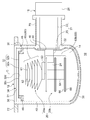
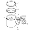
- FIG. 1 schematically shows a cryopump 10 according to an embodiment.
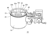
- FIG. 2 is a schematic perspective view of the cryopump 10 shown in FIG.
- the cryopump 10 is attached to, for example, a vacuum chamber of an ion implantation apparatus, a sputtering apparatus, a vapor deposition apparatus, or another vacuum processing apparatus to increase the degree of vacuum inside the vacuum chamber to a level required for a desired vacuum process. used.
- the cryopump 10 has a cryopump suction port (hereinafter, also simply referred to as “suction port”) 12 for receiving a gas to be evacuated from the vacuum chamber. Gas enters the internal space 14 of the cryopump 10 through the intake port 12.
- the axial direction of the cryopump 10 indicates a direction passing through the intake port 12 (that is, a direction along the central axis C in the drawing), and the radial direction is a direction along the intake port 12 (a first direction in a plane perpendicular to the central axis C). ).
- a position relatively close to the intake port 12 in the axial direction may be referred to as “up” and a position relatively far from the intake port 12 may be referred to as “down”.
- a position relatively far from the bottom of the cryopump 10 may be referred to as “up”, and a position relatively close to the bottom may be referred to as “down”.
- a position close to the center of the intake port 12 may be called “inside”
- a position close to the periphery of the intake port 12 may be called “outside”. Note that these expressions have nothing to do with the arrangement when the cryopump 10 is attached to the vacuum chamber.
- the cryopump 10 may be attached to the vacuum chamber with the intake port 12 facing downward in the vertical direction.
- a direction surrounding the axial direction may be referred to as a “circumferential direction”.
- the circumferential direction is a second direction along the intake port 12 (a second direction on a plane perpendicular to the central axis C), and is a tangential direction orthogonal to the radial direction.
- a first displacer and a second displacer are reciprocally disposed inside the first cylinder 23 and the second cylinder 25, respectively.
- a first regenerator and a second regenerator are incorporated in the first displacer and the second displacer, respectively.
- the room temperature section 26 has a drive mechanism (not shown) for reciprocating the first displacer and the second displacer.
- the drive mechanism includes a flow path switching mechanism that switches the flow path of the working gas so as to periodically supply and discharge the working gas (for example, helium) to the inside of the refrigerator 16.
- the radiation shield 30 surrounds the second-stage cryopanel assembly 20.
- the radiation shield 30 provides a cryogenic surface for protecting the second stage cryopanel assembly 20 from radiant heat outside the cryopump 10 or from the cryopump housing 70.
- the radiation shield 30 is thermally coupled to the first cooling stage 22. Therefore, the radiation shield 30 is cooled to the first cooling temperature.
- the radiation shield 30 has a gap between the radiation shield 30 and the second cryopanel assembly 20, and the radiation shield 30 is not in contact with the second cryopanel assembly 20.
- the radiation shield 30 is not in contact with the cryopump housing 70.
- the radiation shield 30 is provided to protect the second-stage cryopanel assembly 20 from radiation heat of the cryopump housing 70.
- the radiation shield 30 extends in a cylindrical shape (for example, a cylindrical shape) in the axial direction from the intake port 12.
- the radiation shield 30 is located between the cryopump housing 70 and the second cryopanel assembly 20 and surrounds the second cryopanel assembly 20.
- the radiation shield 30 has a shield main opening 34 for receiving gas from outside the cryopump 10 into the internal space 14.
- the shield main opening 34 is located at the intake port 12.
- the radiation shield 30 is formed of a high heat conductive metal material such as copper (for example, pure copper). Further, the radiation shield 30 may have a metal plating layer containing, for example, nickel formed on the surface thereof, if necessary, in order to improve corrosion resistance.
- the radiation shield 30 includes a shield front end 36 that defines the shield main opening 34, a shield bottom 38 located on the opposite side of the shield main opening 34, and a shield side 40 that connects the shield front end 36 to the shield bottom 38.
- the shield side portion 40 extends in the axial direction from the shield front end 36 to the side opposite to the shield main opening 34, and extends in the circumferential direction so as to surround the second cooling stage 24.
- the radiation shield 30 is formed in an integral cylindrical shape.
- the radiation shield 30 may be configured to have a cylindrical shape as a whole by a plurality of parts. These parts may be arranged with a gap therebetween.
- the radiation shield 30 may be axially divided into two parts.
- the cryopump 10 includes a heat shield dummy panel 32 arranged at the intake port 12.
- the heat shield dummy panel 32 is attached to the radiation shield 30 via a thermal resistance member 48 such that the dummy panel temperature is higher than the shield cooling temperature (for example, the above-described first cooling temperature).
- the heat shield dummy panel 32 is arranged at the intake port 12 so as to avoid cooling by the refrigerator 16 as much as possible.
- the heat shield dummy panel 32 is not a “cryopanel” intended to be cooled to an extremely low temperature. Therefore, the heat shield dummy panel 32 may be designed such that the temperature of the dummy panel exceeds 0 ° C. during the operation of the cryopump 10. However, depending on the design of the thermal resistance member 48 and / or the method of attaching the heat shield dummy panel 32 to the radiation shield 30, the temperature of the dummy panel may be lower than 0 ° C. during the operation of the cryopump 10. However, even in that case, the dummy panel temperature is maintained at a temperature higher than the shield cooling temperature.
- the heat shield dummy panel 32 protects the second-stage cryopanel assembly 20 from radiant heat from a heat source outside the cryopump 10 (for example, a heat source in a vacuum chamber to which the cryopump 10 is attached). Or the shield main opening 34, and so on). Since the heat shield dummy panel 32 is hardly or not cooled by the refrigerator 16, it does not have a function of condensing gas (for example, a function of exhausting a first type gas such as water vapor).
- the heat shield dummy panel 32 is disposed at a position corresponding to the second-stage cryopanel assembly 20 at the intake port 12, for example, immediately above the second-stage cryopanel assembly 20.
- the heat shield dummy panel 32 occupies a central portion of the opening area of the intake port 12, and forms an annular (for example, annular) open area 51 between the dummy shield panel 32 and the radiation shield 30.
- the heat shield dummy panel 32 need not be formed of a metal having a high thermal conductivity such as copper, but may be formed of, for example, stainless steel or other readily available metal materials.
- the heat shield dummy panel 32 may be formed of a metal material, a resin material (for example, a fluororesin material such as polytetrafluoroethylene), or any other material as long as it is suitable for use in a vacuum environment.
- the thermal resistance member 48 is formed of a material having a lower thermal conductivity than the material of the radiation shield 30 (for example, pure copper as described above) or a heat insulating material.
- the heat resistance member 48 is formed of, for example, a fluororesin material such as polytetrafluoroethylene or another resin material. It may be.
- the heat resistance member 48 is made of metal such as stainless steel. It may be formed of a material.
- the heat resistance member 48 is fixed to the inner peripheral surface of the shield front end 36 corresponding to the dummy panel attachment portion 32b of the heat shield dummy panel 32. As shown, when two dummy panel mounting portions 32b are provided on both sides of the dummy panel central portion 32a, two thermal resistance members 48 are provided.
- the thermal resistance member 48 is fixed to the shield front end 36 by a fastening member such as a bolt or any other appropriate method.
- the distal end of the dummy panel mounting portion 32b is fixed to the heat resistance member 48 by a fastening member such as a bolt or other appropriate method.
- the heat shield dummy panel 32 includes a dummy panel outer surface 32c facing the outside of the cryopump 10 and a dummy panel inner surface 32d facing the inside of the cryopump 10.
- the outer surface 32c of the dummy panel can be called the upper surface of the dummy panel, and the inner surface 32d of the dummy panel can be called the lower surface of the dummy panel.
- the emissivity of the dummy panel outer surface 32c may be higher than the emissivity of the dummy panel inner surface 32d. That is, the reflectance of the dummy panel outer surface 32c may be lower than the reflectance of the dummy panel inner surface 32d. Therefore, the dummy panel outer surface 32c may have a black surface.
- the black surface may be formed, for example, by black painting, black plating, or other blackening treatments.
- the dummy panel outer surface 32c may have a rough surface.
- the outer surface 32c of the dummy panel may be subjected to, for example, sandblasting or other roughening treatment.
- the dummy panel inner surface 32d may have a mirror surface.
- the inner surface 32d of the dummy panel may be subjected to polishing or other mirror finishing.
- the outer surface 32c of the dummy panel is black and the inner surface 32d of the dummy panel is a mirror surface.
- the emissivity of the dummy panel outer surface 32c is regarded as 1.
- the emissivity of the inner surface 32d of the dummy panel is assumed to be, for example, 0.1.
- the amount of heat discharged from the heat shield dummy panel 32 to the outside of the cryopump 10 can be increased.
- the amount of heat discharged from the cryopump 10 by the refrigerator 16 toward the inside of the cryopump 10 from the heat shield dummy panel 32 is reduced. Therefore, the power consumption of the refrigerator 16 can be reduced.
- the upper structure 20a of the second cryopanel assembly 20 includes a plurality of upper cryopanels 60a and a plurality of heat transfer bodies (also referred to as heat transfer spacers) 62.
- the plurality of upper cryopanels 60 a are disposed between the heat-shield dummy panel 32 and the second cooling stage 24 in the axial direction.
- the plurality of heat transfer bodies 62 are arranged in a columnar shape in the axial direction.
- the plurality of upper cryopanels 60 a and the plurality of heat transfer bodies 62 are alternately stacked in the axial direction between the intake port 12 and the second cooling stage 24.
- the centers of the upper cryopanel 60a and the heat transfer body 62 are both located on the central axis C.
- the upper structure 20a is disposed axially above the second cooling stage 24.
- the upper structure 20a is fixed to the second cooling stage 24 via a heat transfer block 63 made of a high heat conductive metal material such as copper (for example, pure copper), and is thermally coupled to the second cooling stage 24. Therefore, the upper structure 20a is cooled to the second cooling temperature.
- the lower structure 20b of the second cryopanel assembly 20 includes a plurality of lower cryopanels 60b and a second cryopanel mounting member 64.
- the plurality of lower cryopanels 60b are arranged between the second cooling stage 24 and the shield bottom 38 in the axial direction.
- the second stage cryopanel mounting member 64 extends downward from the second cooling stage 24 in the axial direction.
- the plurality of lower cryopanels 60 b are mounted on the second cooling stage 24 via the second cryopanel mounting members 64.
- the lower structure 20b is thermally coupled to the second cooling stage 24 and is cooled to the second cooling temperature.
- one or more upper cryopanels 60a closest to the heat shield dummy panel 32 in the axial direction among the plurality of upper cryopanels 60a are flat plates (for example, disk-shaped) and are arranged perpendicular to the central axis C. Have been.
- the remaining upper cryopanel 60a has an inverted truncated cone shape, and a circular bottom surface is arranged perpendicular to the central axis C.
- the diameters of the plurality of upper cryopanels 60a gradually increase downward in the axial direction.
- the inverted truncated cone-shaped upper cryopanel 60a is nested.
- Each heat transfer body 62 has a columnar shape.
- the heat transfer body 62 may have a relatively short cylindrical shape, and may have an axial height smaller than the diameter of the heat transfer body 62.
- a cryopanel such as the adsorption cryopanel 60 is generally formed of a highly heat-conductive metal material such as copper (for example, pure copper), and its surface is coated with a metal layer such as nickel when required.
- the heat transfer body 62 may be formed of a material different from that of the cryopanel.
- the heat transfer body 62 may be formed of a metal material, such as aluminum or an aluminum alloy, having a lower thermal conductivity but a lower density than the adsorption cryopanel 60. By doing so, the thermal conductivity of the heat transfer body 62 and the reduction in weight can be compatible to some extent, which helps to reduce the cooling time of the second-stage cryopanel assembly 20.
- the lower cryopanel 60b is a flat plate, for example, in a disk shape.
- the lower cryopanel 60b has a larger diameter than the upper cryopanel 60a.
- a cutout may be formed in the lower cryopanel 60b from a part of the outer periphery to the center for attachment to the second cryopanel attachment member 64.
- a large number of activated carbon particles are adhered in an irregular arrangement in a state of being densely arranged on the surface of the adsorption cryopanel 60.
- the activated carbon particles are formed, for example, in a columnar shape.
- the shape of the adsorbent does not have to be a columnar shape, and may be, for example, a spherical shape, another molded shape, or an irregular shape.
- the arrangement of the adsorbents on the panel may be a regular arrangement or an irregular arrangement.
- At least a portion of the surface of the second-stage cryopanel assembly 20 is provided with a condensation region for capturing a condensable gas by condensation.
- the condensation area is, for example, an area where the adsorbent is missing on the surface of the cryopanel, and the surface of the cryopanel base material, for example, the metal surface is exposed.
- the upper surface, the outer peripheral portion of the upper surface, or the outer peripheral portion of the lower surface of the adsorption cryopanel 60 may be a condensation region.
- the second-stage cryopanel assembly 20 has a large number of adsorption cryopanels 60 (i.e., a plurality of upper cryopanels 60a and lower cryopanels 60b), and thus has high exhaust performance for non-condensable gases.
- the second-stage cryopanel assembly 20 can exhaust hydrogen gas at a high exhaust speed.
- Each of the plurality of suction cryopanels 60 has a suction area 66 at a position that is not visible from outside the cryopump 10. Therefore, the second-stage cryopanel assembly 20 is configured such that all or most of the suction area 66 is not completely visible from outside the cryopump 10.
- the cryopump 10 can also be called an adsorbent non-exposed cryopump.
- the inlet 12 is defined by the front end of the cryopump housing 70.
- the cryopump housing 70 has an inlet flange 72 extending radially outward from a front end thereof.
- the intake port flange 72 is provided over the entire circumference of the cryopump housing 70.
- the cryopump 10 is attached to a vacuum chamber to be evacuated using an inlet flange 72.
- the operation of the cryopump 10 having the above configuration will be described below.
- the inside of the vacuum chamber is first roughly evacuated to about 1 Pa by another appropriate roughing pump before the operation. Thereafter, the cryopump 10 is operated.
- the first cooling stage 22 and the second cooling stage 24 are cooled to the first cooling temperature and the second cooling temperature, respectively. Therefore, the radiation shield 30 and the second-stage cryopanel assembly 20 that are thermally coupled thereto are also cooled to the first cooling temperature and the second cooling temperature, respectively.
- the heat shield dummy panel 32 is attached to the radiation shield 30 via the heat resistance member 48, the heat shield dummy panel 32 is thermally insulated from the radiation shield 30 or has a high thermal resistance. Connected through. Therefore, the heat shield dummy panel 32 is maintained at, for example, room temperature or a temperature higher than 0 ° C. during the operation of the cryopump 10. Since the heat shield dummy panel 32 is hardly or not cooled by the refrigerator 16, most or all of the gas that contacts the heat shield dummy panel 32 does not condense on the heat shield dummy panel 32.
- a gas having a sufficiently low vapor pressure (for example, 10 ⁇ 8 Pa or less) condenses on the surface of the radiation shield 30.
- This gas may be referred to as a first type gas.
- the first type gas is, for example, water vapor.
- the radiation shield 30 can exhaust the first type gas.
- the gas whose vapor pressure is not sufficiently low at the first cooling temperature is reflected by the radiation shield 30, and a part of the gas is directed to the second-stage cryopanel assembly 20.
- the gas that has entered the internal space 14 is cooled by the second-stage cryopanel assembly 20.
- the first type gas reflected by the radiation shield 30 condenses on the surface of the condensation area of the adsorption cryopanel 60.
- a gas whose vapor pressure is sufficiently low (for example, 10 ⁇ 8 Pa or less) condenses on the surface of the condensation area of the adsorption cryopanel 60 at the second cooling temperature.
- This gas may be referred to as a second type gas.
- the second type gas is, for example, nitrogen (N 2 ) or argon (Ar).
- the second stage cryopanel assembly 20 can exhaust the second type gas.
- the thermal resistance member 48 is formed of a material having a lower thermal conductivity than the material of the radiation shield 30 or a heat insulating material. This makes it easy to connect the heat shield dummy panel 32 to the radiation shield 30 via a high thermal resistance or to thermally insulate the heat shield dummy panel 32 from the radiation shield 30. As a result, the temperature of the dummy panel can be significantly increased as compared with the shield cooling temperature.
- the amount of heat discharged from the heat shield dummy panel 32 to the outside of the cryopump 10 can be increased.
- the amount of heat directed from the heat shield dummy panel 32 to the inside of the cryopump 10 can be reduced.
- Dummy panel temperature exceeds 0 ° C. Therefore, it is guaranteed that the heat shield dummy panel 32 does not provide the exhaust capability of the first type gas.
- the ice layer due to the condensation of water is prevented from covering the surface of the heat shield dummy panel 32 (for example, the dummy panel outer surface 32c). Therefore, during operation of the cryopump 10, an increase in reflectance (a decrease in emissivity) that can occur if an ice layer is formed can be suppressed.
- the heat shield dummy panel 32 does not need to be cooled, it does not need to be formed of a metal having a high thermal conductivity such as pure copper, unlike a cryopanel arranged in an intake port in a conventional cryopump. Also, plating of nickel or the like is unnecessary. In addition, for the same reason, the heat shield dummy panel 32 may be thinner than the cryopanel. Therefore, the heat shield dummy panel 32 can be manufactured by a common processing method using an easily available material such as stainless steel, and is inexpensive.
- the heat shield dummy panel 32 is attached to the radiation shield 30 via the heat resistance member 48.
- the heat shield dummy panel 32 may be thermally coupled to the cryopump housing 70 such that the dummy panel temperature is higher than the shield cooling temperature. Such an embodiment is described below.
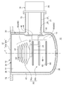
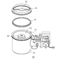
- FIG. 3 schematically shows a cryopump 10 according to another embodiment.
- the heat shield dummy panel 32 arranged at the intake port 12 is attached to the intake port flange 72.
- the heat shield dummy panel 32 extends in the radial direction outward from the dummy panel central portion 32 a disposed in the central portion of the intake port 12 and the dummy panel central portion 32 a.
- a dummy panel mounting portion 32b is fixed to the inner periphery of the inlet flange 72 by a fastening member such as a bolt or other appropriate method.
- the heat shield dummy panel 32 is thermally coupled to the cryopump housing 70, it can be maintained at a dummy panel temperature significantly higher than the shield cooling temperature, for example, a temperature higher than 0 ° C. (particularly, room temperature). Easy. Further, since the heat resistance member 48 is not required unlike the embodiment shown in FIGS. 1 and 2, it is advantageous in that the mounting structure of the heat shield dummy panel 32 can be simplified.
- the heat shield dummy panel 32 may be attached to the inlet flange 72 via another member, and may be thermally coupled to the cryopump housing 70.
- the heat shield dummy panel 32 may be attached to a mating flange on which the inlet flange 72 is mounted, or a center ring sandwiched between the inlet flange 72 and the mating flange. Such an embodiment is described below.
- the heat shield dummy panel 32 is attached to the mating flange 74 to which the inlet flange 72 is attached.
- the mating flange 74 may be, for example, a vacuum flange of a gate valve to which the cryopump 10 is attached.
- the mating flange 74 may be a vacuum flange of a vacuum chamber to which the cryopump 10 is attached.
- a center ring 76 is provided between the inlet flange 72 and the mating flange 74. As is known, when the inlet flange 72 is mounted on the mating flange 74, the center ring 76 is sandwiched between the inlet flange 72 and the mating flange 74.
- the heat shield dummy panel 32 is attached to the inlet flange 72 via the mating flange 74 and is thermally connected to the cryopump housing 70. Even in this case, the heat shield dummy panel 32 has a dummy panel temperature higher than the shield cooling temperature, for example, room temperature, during the operation of the cryopump 10. Therefore, similarly to the above-described embodiment, the heat shield dummy panel 32 can provide a function of protecting the second-stage cryopanel assembly 20 from radiant heat.
- FIG. 6 is a schematic perspective view of a cryopump 10 according to still another embodiment.
- FIG. 7 is a partial sectional view schematically showing a part of the cryopump 10 shown in FIG.
- FIG. 6 shows a part of a cross section of the cryopump 10 in a plane including the cryopump central axis as in FIG. 1, and shows the heat shield dummy panel 32 arranged in the intake port 12 and members around it. .
- the heat shield dummy panel 32 can be regarded as constituting a part of the cryopump 10.
- the mating flange 74 to which the heat shield dummy panel 32 is attached, or a vacuum device such as a gate valve having the mating flange 74, or the center ring 76 is provided to the user by the cryopump manufacturer as an accessory of the cryopump 10. You may.
- the emissivity of the outer surface of the dummy panel may be higher than the emissivity of the inner surface of the dummy panel.
- the temperature of the dummy panel is maintained so as to exceed 0 ° C. during the operation of the cryopump 10, so that the heat-insulating dummy panel 32 does not provide the exhaust capability of the first type gas.
- the heat shield dummy panel 32 may be cooled to a dummy panel temperature higher than the shield cooling temperature and lower than the condensation temperature of the first type gas (for example, water vapor). In this manner, the heat shield dummy panel 32 may have a certain degree of exhaust capability of the first-class gas, although not as much as the first-stage cryopanel arranged at the intake port in the conventional cryopump.
- the heat shield dummy panel 32 is formed in a disk shape from a single plate, but the heat shield dummy panel 32 may have other shapes.
- the heat shield dummy panel 32 may be, for example, a plate having a rectangular shape or another shape.
- the heat shield dummy panel 32 may be a louver or a chevron formed in a concentric shape or a lattice shape.
- the present invention can be used in the field of cryopump.
- cryopump 10 cryopump, 12 inlet, 30 radiation shield, 32 heat shield dummy panel, 32c dummy panel outer surface, 32d dummy panel inner surface, 48 thermal resistance member, 70 cryopump housing, 72 inlet flange, 74 mating flange, 76 centering .
Landscapes
- Engineering & Computer Science (AREA)
- Mechanical Engineering (AREA)
- General Engineering & Computer Science (AREA)
- Compressors, Vaccum Pumps And Other Relevant Systems (AREA)
Abstract
Description
Claims (11)
- クライオポンプ吸気口を有するクライオポンプハウジングと、
前記クライオポンプハウジングと非接触に前記クライオポンプハウジング内に配置され、シールド冷却温度に冷却される放射シールドと、
前記クライオポンプ吸気口に配置された遮熱ダミーパネルであって、前記シールド冷却温度よりも高いダミーパネル温度となるように、前記放射シールドに熱抵抗部材を介して取り付けられた遮熱ダミーパネルと、を備えることを特徴とするクライオポンプ。 A cryopump housing having a cryopump inlet;
A radiation shield disposed in the cryopump housing in a non-contact manner with the cryopump housing and cooled to a shield cooling temperature;
A heat shield dummy panel disposed at the cryopump intake port, wherein the heat shield dummy panel attached to the radiation shield via a thermal resistance member so that the dummy panel temperature is higher than the shield cooling temperature. A cryopump comprising: - 前記熱抵抗部材は、前記放射シールドの材料より熱伝導率の低い材料または断熱材料で形成されていることを特徴とする請求項1に記載のクライオポンプ。 The cryopump according to claim 1, wherein the thermal resistance member is formed of a material having a lower thermal conductivity than a material of the radiation shield or a heat insulating material.
- クライオポンプ吸気口を有するクライオポンプハウジングと、
前記クライオポンプハウジングと非接触に前記クライオポンプハウジング内に配置され、シールド冷却温度に冷却される放射シールドと、
前記クライオポンプ吸気口に配置された遮熱ダミーパネルであって、前記シールド冷却温度よりも高いダミーパネル温度となるように、前記クライオポンプハウジングに熱的に結合された遮熱ダミーパネルと、を備えることを特徴とするクライオポンプ。 A cryopump housing having a cryopump inlet;
A radiation shield disposed in the cryopump housing in a non-contact manner with the cryopump housing and cooled to a shield cooling temperature;
A heat insulation dummy panel disposed at the cryopump intake port, wherein a heat insulation dummy panel thermally coupled to the cryopump housing so that the temperature of the dummy panel is higher than the shield cooling temperature. A cryopump characterized by comprising: - 前記クライオポンプハウジングは、前記クライオポンプ吸気口を定める吸気口フランジを備え、
前記遮熱ダミーパネルは、前記吸気口フランジ、前記吸気口フランジが装着される相手フランジ、または前記吸気口フランジと前記相手フランジとの間に挟み込まれるセンターリングに取り付けられていることを特徴とする請求項3に記載のクライオポンプ。 The cryopump housing includes an inlet flange that defines the cryopump inlet,
The heat shield dummy panel is attached to the inlet flange, a mating flange to which the inlet flange is attached, or a center ring sandwiched between the inlet flange and the mating flange. The cryopump according to claim 3. - 前記遮熱ダミーパネルは、前記クライオポンプの外側に向けられたダミーパネル外面と、前記クライオポンプの内側に向けられたダミーパネル内面と、を備え、
前記ダミーパネル外面の輻射率が前記ダミーパネル内面の輻射率より高いことを特徴とする請求項1から4のいずれかに記載のクライオポンプ。 The heat shield dummy panel includes a dummy panel outer surface directed toward the outside of the cryopump, and a dummy panel inner surface directed toward the inside of the cryopump,
The cryopump according to any one of claims 1 to 4, wherein the emissivity of the outer surface of the dummy panel is higher than the emissivity of the inner surface of the dummy panel. - 前記ダミーパネル外面は、黒色であり、前記ダミーパネル内面は、鏡面であることを特徴とする請求項5に記載のクライオポンプ。 6. The cryopump according to claim 5, wherein the outer surface of the dummy panel is black, and the inner surface of the dummy panel is a mirror surface.
- 前記ダミーパネル温度は、0℃を超えることを特徴とする請求項1から6のいずれかに記載のクライオポンプ。 7. The cryopump according to claim 1, wherein the temperature of the dummy panel exceeds 0 ° C.
- 前記遮熱ダミーパネルは、前記放射シールドとは異なる材料で形成されていることを特徴とする請求項1から7のいずれかに記載のクライオポンプ。 The cryopump according to any one of claims 1 to 7, wherein the heat shield dummy panel is formed of a material different from the radiation shield.
- 前記遮熱ダミーパネルは、前記放射シールドよりも熱伝導率が低い材料で形成されていることを特徴とする請求項8に記載のクライオポンプ。 The cryopump according to claim 8, wherein the heat shield dummy panel is formed of a material having a lower thermal conductivity than the radiation shield.
- 前記放射シールドよりも低温に冷却されるトップクライオパネルをさらに備え、
前記トップクライオパネルは、前記遮熱ダミーパネルの直下に位置するとともに前記遮熱ダミーパネルと直接対向することを特徴とする請求項1から9のいずれかに記載のクライオポンプ。 Further comprising a top cryopanel cooled to a lower temperature than the radiation shield,
The cryopump according to any one of claims 1 to 9, wherein the top cryopanel is located directly below the heat shield dummy panel and directly faces the heat shield dummy panel. - 前記放射シールドよりも低温に冷却されるクライオパネルアセンブリであって、複数のクライオパネルと、軸方向に柱状に配列された複数の伝熱体と、を備え、前記複数のクライオパネルおよび前記複数の伝熱体が軸方向に積み重ねられているクライオパネルアセンブリをさらに備え、
前記遮熱ダミーパネルは、前記クライオパネルアセンブリの軸方向上方に配置されていることを特徴とする請求項1から10のいずれかに記載のクライオポンプ。 A cryopanel assembly that is cooled to a lower temperature than the radiation shield, comprising a plurality of cryopanels and a plurality of heat conductors arranged in a columnar shape in the axial direction, the plurality of cryopanels and the plurality of Further comprising a cryopanel assembly in which the heat transfer bodies are stacked in the axial direction,
The cryopump according to claim 1, wherein the heat shield dummy panel is disposed axially above the cryopanel assembly.
Priority Applications (4)
| Application Number | Priority Date | Filing Date | Title |
|---|---|---|---|
| JP2020541070A JP7339950B2 (en) | 2018-09-06 | 2019-08-01 | cryopump |
| CN201980056012.7A CN112601889B (en) | 2018-09-06 | 2019-08-01 | Low-temperature pump |
| KR1020217005154A KR102663120B1 (en) | 2018-09-06 | 2019-08-01 | cryopump |
| US17/193,696 US20210190058A1 (en) | 2018-09-06 | 2021-03-05 | Cryopump |
Applications Claiming Priority (2)
| Application Number | Priority Date | Filing Date | Title |
|---|---|---|---|
| JP2018-167178 | 2018-09-06 | ||
| JP2018167178 | 2018-09-06 |
Related Child Applications (1)
| Application Number | Title | Priority Date | Filing Date |
|---|---|---|---|
| US17/193,696 Continuation US20210190058A1 (en) | 2018-09-06 | 2021-03-05 | Cryopump |
Publications (1)
| Publication Number | Publication Date |
|---|---|
| WO2020049917A1 true WO2020049917A1 (en) | 2020-03-12 |
Family
ID=69722865
Family Applications (1)
| Application Number | Title | Priority Date | Filing Date |
|---|---|---|---|
| PCT/JP2019/030303 WO2020049917A1 (en) | 2018-09-06 | 2019-08-01 | Cryopump |
Country Status (6)
| Country | Link |
|---|---|
| US (1) | US20210190058A1 (en) |
| JP (1) | JP7339950B2 (en) |
| KR (1) | KR102663120B1 (en) |
| CN (1) | CN112601889B (en) |
| TW (1) | TWI750505B (en) |
| WO (1) | WO2020049917A1 (en) |
Families Citing this family (2)
| Publication number | Priority date | Publication date | Assignee | Title |
|---|---|---|---|---|
| US11859160B2 (en) * | 2019-12-18 | 2024-01-02 | Spokane Stainless Technologies, Inc. | Oval-shaped metal tank systems |
| JP2022092331A (en) * | 2020-12-10 | 2022-06-22 | アルバック・クライオ株式会社 | Cryopump and heat insulation structure for cryopump |
Citations (4)
| Publication number | Priority date | Publication date | Assignee | Title |
|---|---|---|---|---|
| JPH0565874A (en) * | 1991-03-28 | 1993-03-19 | Daikin Ind Ltd | Vacuum cryopump |
| US5228299A (en) * | 1992-04-16 | 1993-07-20 | Helix Technology Corporation | Cryopump water drain |
| US6122920A (en) * | 1998-12-22 | 2000-09-26 | The United States Of America As Represented By The United States Department Of Energy | High specific surface area aerogel cryoadsorber for vacuum pumping applications |
| JP2012237263A (en) * | 2011-05-12 | 2012-12-06 | Sumitomo Heavy Ind Ltd | Cryopump, and manufacturing method thereof |
Family Cites Families (15)
| Publication number | Priority date | Publication date | Assignee | Title |
|---|---|---|---|---|
| NL6408166A (en) * | 1964-07-17 | 1966-01-18 | ||
| JPS61169681A (en) * | 1985-01-23 | 1986-07-31 | Hitachi Ltd | Complex cryopump |
| GB8526191D0 (en) * | 1985-10-23 | 1985-11-27 | Boc Group Plc | Cryopumps |
| KR930702618A (en) * | 1990-11-19 | 1993-09-09 | 하랄트 고트하르트 . 페터 좀머캄프 | Regeneration of low temperature pump and low temperature pump for carrying out the method |
| US5156007A (en) * | 1991-01-30 | 1992-10-20 | Helix Technology Corporation | Cryopump with improved second stage passageway |
| JP2719298B2 (en) * | 1993-07-29 | 1998-02-25 | アプライド マテリアルズ インコーポレイテッド | Cooling structure of vacuum equipment |
| JP4287422B2 (en) * | 2005-11-10 | 2009-07-01 | 住友重機械工業株式会社 | Cryopump, sputtering apparatus, and semiconductor manufacturing apparatus |
| JP2008223538A (en) * | 2007-03-09 | 2008-09-25 | Canon Anelva Technix Corp | Cryo pump |
| JP5193786B2 (en) | 2008-10-01 | 2013-05-08 | 住友重機械工業株式会社 | Cryopump |
| JP5527110B2 (en) * | 2010-08-27 | 2014-06-18 | アイシン精機株式会社 | Cryopump |
| JP6031451B2 (en) * | 2011-02-09 | 2016-11-24 | ブルックス オートメーション インコーポレイテッド | Cryopump |
| JP6057782B2 (en) * | 2013-03-05 | 2017-01-11 | 住友重機械工業株式会社 | Cryopump |
| JP6415230B2 (en) * | 2014-10-07 | 2018-10-31 | 住友重機械工業株式会社 | Cryopump |
| JP6710604B2 (en) * | 2015-08-10 | 2020-06-17 | 住友重機械工業株式会社 | Cryopump |
| JP6871751B2 (en) * | 2017-02-07 | 2021-05-12 | 住友重機械工業株式会社 | Cryopump |
-
2019
- 2019-08-01 CN CN201980056012.7A patent/CN112601889B/en active Active
- 2019-08-01 JP JP2020541070A patent/JP7339950B2/en active Active
- 2019-08-01 KR KR1020217005154A patent/KR102663120B1/en active IP Right Grant
- 2019-08-01 WO PCT/JP2019/030303 patent/WO2020049917A1/en active Application Filing
- 2019-08-30 TW TW108131180A patent/TWI750505B/en active
-
2021
- 2021-03-05 US US17/193,696 patent/US20210190058A1/en active Pending
Patent Citations (4)
| Publication number | Priority date | Publication date | Assignee | Title |
|---|---|---|---|---|
| JPH0565874A (en) * | 1991-03-28 | 1993-03-19 | Daikin Ind Ltd | Vacuum cryopump |
| US5228299A (en) * | 1992-04-16 | 1993-07-20 | Helix Technology Corporation | Cryopump water drain |
| US6122920A (en) * | 1998-12-22 | 2000-09-26 | The United States Of America As Represented By The United States Department Of Energy | High specific surface area aerogel cryoadsorber for vacuum pumping applications |
| JP2012237263A (en) * | 2011-05-12 | 2012-12-06 | Sumitomo Heavy Ind Ltd | Cryopump, and manufacturing method thereof |
Also Published As
| Publication number | Publication date |
|---|---|
| CN112601889B (en) | 2023-02-28 |
| KR20210044229A (en) | 2021-04-22 |
| CN112601889A (en) | 2021-04-02 |
| TWI750505B (en) | 2021-12-21 |
| JPWO2020049917A1 (en) | 2021-08-12 |
| JP7339950B2 (en) | 2023-09-06 |
| US20210190058A1 (en) | 2021-06-24 |
| KR102663120B1 (en) | 2024-05-07 |
| TW202204769A (en) | 2022-02-01 |
| TW202010941A (en) | 2020-03-16 |
Similar Documents
| Publication | Publication Date | Title |
|---|---|---|
| US20210190058A1 (en) | Cryopump | |
| CN110291291B (en) | Low-temperature pump | |
| US11828521B2 (en) | Cryopump | |
| JP6629074B2 (en) | Cryopump | |
| TWI838647B (en) | Low temperature pump | |
| WO2023145296A1 (en) | Cryopump | |
| US11512687B2 (en) | Cryopump | |
| TWI712738B (en) | Cryopump |
Legal Events
| Date | Code | Title | Description |
|---|---|---|---|
| 121 | Ep: the epo has been informed by wipo that ep was designated in this application |
Ref document number: 19857793 Country of ref document: EP Kind code of ref document: A1 |
|
| ENP | Entry into the national phase |
Ref document number: 2020541070 Country of ref document: JP Kind code of ref document: A |
|
| ENP | Entry into the national phase |
Ref document number: 20217005154 Country of ref document: KR Kind code of ref document: A |
|
| NENP | Non-entry into the national phase |
Ref country code: DE |
|
| 122 | Ep: pct application non-entry in european phase |
Ref document number: 19857793 Country of ref document: EP Kind code of ref document: A1 |