WO2020045232A1 - 地図生成装置及び地図生成プログラム - Google Patents
地図生成装置及び地図生成プログラム Download PDFInfo
- Publication number
- WO2020045232A1 WO2020045232A1 PCT/JP2019/032846 JP2019032846W WO2020045232A1 WO 2020045232 A1 WO2020045232 A1 WO 2020045232A1 JP 2019032846 W JP2019032846 W JP 2019032846W WO 2020045232 A1 WO2020045232 A1 WO 2020045232A1
- Authority
- WO
- WIPO (PCT)
- Prior art keywords
- landmark
- segment
- common
- unit
- setting
- Prior art date
- Legal status (The legal status is an assumption and is not a legal conclusion. Google has not performed a legal analysis and makes no representation as to the accuracy of the status listed.)
- Ceased
Links
Images











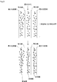
Classifications
-
- G—PHYSICS
- G01—MEASURING; TESTING
- G01C—MEASURING DISTANCES, LEVELS OR BEARINGS; SURVEYING; NAVIGATION; GYROSCOPIC INSTRUMENTS; PHOTOGRAMMETRY OR VIDEOGRAMMETRY
- G01C21/00—Navigation; Navigational instruments not provided for in groups G01C1/00 - G01C19/00
- G01C21/26—Navigation; Navigational instruments not provided for in groups G01C1/00 - G01C19/00 specially adapted for navigation in a road network
- G01C21/28—Navigation; Navigational instruments not provided for in groups G01C1/00 - G01C19/00 specially adapted for navigation in a road network with correlation of data from several navigational instruments
-
- G—PHYSICS
- G08—SIGNALLING
- G08G—TRAFFIC CONTROL SYSTEMS
- G08G1/00—Traffic control systems for road vehicles
- G08G1/123—Traffic control systems for road vehicles indicating the position of vehicles, e.g. scheduled vehicles; Managing passenger vehicles circulating according to a fixed timetable, e.g. buses, trains, trams
- G08G1/127—Traffic control systems for road vehicles indicating the position of vehicles, e.g. scheduled vehicles; Managing passenger vehicles circulating according to a fixed timetable, e.g. buses, trains, trams to a central station ; Indicators in a central station
- G08G1/13—Traffic control systems for road vehicles indicating the position of vehicles, e.g. scheduled vehicles; Managing passenger vehicles circulating according to a fixed timetable, e.g. buses, trains, trams to a central station ; Indicators in a central station the indicator being in the form of a map
-
- G—PHYSICS
- G09—EDUCATION; CRYPTOGRAPHY; DISPLAY; ADVERTISING; SEALS
- G09B—EDUCATIONAL OR DEMONSTRATION APPLIANCES; APPLIANCES FOR TEACHING, OR COMMUNICATING WITH, THE BLIND, DEAF OR MUTE; MODELS; PLANETARIA; GLOBES; MAPS; DIAGRAMS
- G09B29/00—Maps; Plans; Charts; Diagrams, e.g. route diagram
Definitions
- the present disclosure relates to a map generation device and a map generation program.
- Patent Literature 1 discloses a method of calculating a center line of a road using a traveling locus of a vehicle based on GPS (Global Positioning System) coordinates.
- Patent Document 1 has a problem in that if the number of samples is small, the accuracy cannot be increased, and a large number of samples are required to increase the accuracy, because of the large variation in GPS coordinates. is there. Under such circumstances, a mechanism for generating a map with high accuracy even with a small number of samples is required.
- the present disclosure aims to appropriately generate a high-accuracy map with a small number of samples.
- the segment acquisition unit acquires a segment including a lane marking and a landmark on a road.
- the common landmark setting unit sets a common landmark common to other segments in the acquired segment.
- the marking line setting unit sets the marking line in the segment using the set common landmark.
- the map data generating unit identifies the lane marking in the set segment as a lane marking on the map and generates map data.
- a lane marking in the segment is set using a common landmark common to other segments, and the lane marking in the set segment is defined as a lane marking on the map.
- Map data is generated specifically. Rather than using GPS coordinates having large variations, a common landmark is used to set a lane marking in a segment, and the set lane marking is specified as a lane marking on the map to generate map data. Even with the number of samples, a highly accurate map can be appropriately generated.
- FIG. 1 is a functional block diagram illustrating an entire configuration of a map generation system according to an embodiment.
- FIG. 2 is a functional block diagram of a control unit in the server
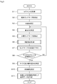
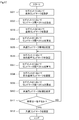
- FIG. 3 is a flowchart (part 1)
- FIG. 4 is a flowchart (Part 2).
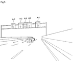
- FIG. 5 is a diagram showing a mode in which the signs are arranged side by side
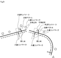
- FIG. 6 is a diagram showing a mode of setting an integrated landmark
- FIG. 7 is a diagram showing an aspect of setting a common landmark.
- FIG. 8 is a diagram illustrating a state before the direction of the segment is corrected, FIG.
- FIG. 9 is a diagram (part 1) illustrating a mode in which the direction of the segment is being corrected.
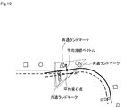
- FIG. 10 is a diagram (part 2) illustrating a state in which the direction of the segment is being corrected.
- FIG. 11 is a diagram (part 3) illustrating a state in which the direction of the segment is being corrected.
- FIG. 12 is a diagram showing a state after correcting the direction of the segment,
- FIG. 13 is a diagram showing a mode of correcting the segment size and the linear distortion,
- FIG. 14 is a diagram illustrating an aspect of setting a lane marking;
- FIG. 15 is a diagram illustrating a process of determining the overlapping of the positions of a plurality of segments.
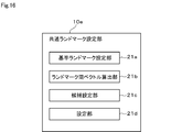
- FIG. 16 is a functional block diagram of a common landmark setting unit.
- FIG. 16 is a functional block diagram of a common landmark setting unit.
- FIG. 17 is a flowchart (part 3).
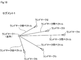
- FIG. 18 is a diagram (part 1) illustrating a vector between landmarks.
- FIG. 19 is a diagram (part 2) illustrating an inter-landmark vector.
- FIG. 20 is a diagram illustrating an aspect of setting a common landmark.
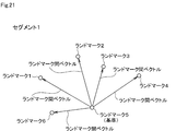
- FIG. 21 is a diagram illustrating a landmark vector (part 3).
- FIG. 22 is a diagram (part 4) illustrating an inter-landmark vector.
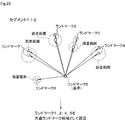
- FIG. 23 is a diagram showing an aspect of setting a common landmark
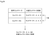
- FIG. 24 is a diagram (part 1) illustrating a process of setting a common landmark
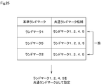
- FIG. 25 is a diagram (part 2) illustrating a process of setting a common landmark.
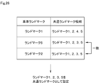
- FIG. 26 is a diagram (part 3) illustrating a process of setting a common landmark;
- FIG. 3) illustrating a process of setting a common landmark
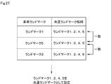
- FIG. 27 is a diagram (part 4) illustrating a process of setting a common landmark.
- FIG. 28 is a flowchart (part 4).
- FIG. 29 is a diagram (part 1) illustrating a process of setting a lane marking;
- FIG. 30 is a diagram (part 2) for explaining the processing for setting the lane markings;
- FIG. 31 is a diagram (part 3) for explaining the processing for setting the lane markings.
- the map generation system 1 is configured so that data communication can be performed between an in-vehicle device 2 mounted on a vehicle side and a server 3 (corresponding to a map generation device) disposed on a network side. ing.
- the in-vehicle device 2 and the server 3 are in a plural-to-one relationship, and the server 3 can perform data communication with the in-vehicle devices 2.
- the in-vehicle device 2 includes a control unit 4, a data communication unit 5, an image data input unit 6, and a storage device 7, and each functional block is configured to be able to perform data communication via the internal bus 8.
- the control unit 4 includes a microcomputer having a CPU (Central Processing Unit), a ROM (Read Only Memory), a RAM (Random Access Memory), and an I / O (Input / Output).
- the microcomputer executes a process corresponding to the computer program by executing the computer program stored in the non-transitional substantial storage medium, and controls the overall operation of the vehicle-mounted device 2.
- the data communication unit 5 controls data communication with the server 3.
- the in-vehicle camera 9 is provided separately from the in-vehicle device 2, captures an image of the front of the vehicle, and outputs the captured image data to the in-vehicle device 2.
- the image data input unit 6 outputs the input image data to the control unit 4.
- the control unit 4 is generated from a vehicle position measured using a GPS signal received by a GPS (Global Positioning System) receiver, a time at which the vehicle position was measured, and image data input from the on-board camera 9.
- the data including the segment is stored in the storage device 7 periodically as probe data.
- the control unit 4 reads the probe data from the storage device 7 every time a predetermined time elapses or every time the traveling distance of the vehicle reaches the predetermined distance, and transmits the read probe data from the data communication unit 5 to the server 3. .
- a segment is generated from image data captured by the vehicle-mounted camera 9.
- a segment is generated from survey data acquired by a measuring device different from the vehicle-mounted camera 9. May be.
- the image data and the survey data may be used together, and a segment may be generated from the image data and the survey data.
- the server 3 includes a control unit 10, a data communication unit 11, and a storage device 12, and each functional block is configured to be able to perform data communication via the internal bus 13.
- the control unit 10 is configured by a microcomputer having a CPU, a ROM, a RAM, and an I / O.
- the microcomputer executes a process corresponding to the computer program by executing the computer program stored in the non-transitional substantial storage medium, and controls the overall operation of the server 3.
- Computer programs executed by the microcomputer include a map generation program.
- the data communication unit 11 controls data communication with the on-vehicle device 2.
- the storage device 12 includes a probe data storage unit 12a that stores probe data, and a map data storage unit 12b that stores map data.
- the control unit 10 stores the received probe data in the probe data storage unit 12a. That is, since the in-vehicle device 2 and the server 3 are in a plural-to-one relationship, the control unit 10 stores the plurality of probe data received from the plurality of in-vehicle devices 2 in the probe data storage unit 12a.
- the control unit 10 stores the generated map data in the map data storage unit 12b.
- the control unit 10 reads the map data stored in the map data storage unit 12b, and distributes the read map data from the data communication unit 11 to the vehicle-mounted device 2.
- the control unit 10 includes a segment acquisition unit 10a, an integrated landmark setting unit 10b, a position correction unit 10c, an overlap determination unit 10d, a common landmark setting unit 10e, and a direction correction unit 10f.
- the segment acquisition unit 10a reads the probe data stored in the probe data storage unit 12a of the storage device 12, and acquires a segment from the read probe data.
- the segment is a unit including a division line painted on the road, landmarks indicating marks such as signs and signboards installed on the road, and a traveling locus of the vehicle.
- the segment acquisition unit 10a considers that there is a landmark that cannot be set as a common landmark when performing processing for setting a common landmark as described later, and includes as many landmarks as possible. It is desirable to get the segment that is.
- the segment acquisition unit 10a compares the number of landmarks included in the segment with a predetermined number, sets a segment including a predetermined number or more of landmarks as an acquisition target, and includes a predetermined number or more of landmarks. A segment that does not need to be acquired need not be acquired. In addition, the segment acquisition unit 10a determines the detection accuracy of the landmark, and sets a segment including a predetermined number or more of landmarks whose detection level is equal to or higher than a predetermined level as an acquisition target, and detects a landmark whose detection level is equal to or higher than a predetermined level. A segment that is not included in a predetermined number or more may not be an acquisition target.
- the predetermined number and the predetermined level may be fixed values, or may be variable values determined according to, for example, the traveling position of the vehicle or the traveling environment. That is, if the predetermined number is set to a large value while the vehicle is traveling in an area where the number of landmarks is relatively small, the number of segments that can be acquired may become too small. Therefore, the predetermined number is set to a small value. It is desirable. Conversely, if the predetermined number is set to a small value while the vehicle is traveling in an area where the number of landmarks is relatively large, the number of segments that can be acquired may become excessive, so the predetermined number may be increased. It is desirable to set by value. The same applies to the predetermined level.
- the predetermined level is set to a high level while the vehicle is running in an environment where the detection environment is relatively poor due to the weather or the like, there is a possibility that the number of segments that can be acquired will be too small. Therefore, it is desirable to set the predetermined level at a low level. On the contrary, if the predetermined level is set at a low level while the vehicle is running in an environment in which the detection environment is relatively favorable, there is a possibility that the number of segments that can be acquired may become excessive, so that the predetermined level may be increased. It is desirable to set at the level.
- the integrated landmark setting unit 10b integrates a plurality of landmarks in the acquired segment and sets an integrated landmark.
- the position correcting unit 10c corrects the position of the segment according to the GPS coordinates at both ends of the acquired segment.
- the overlap determination unit 10d determines the overlap of the corrected position of the segment. That is, when it is determined that there are a plurality of segments having the same GPS coordinates at both ends of the segment, the overlap determination unit 10d determines that the plurality of segments overlap.
- the common landmark setting unit 10e sets a common landmark common to other segments in the segment whose overlap has been determined when the overlap of the segment positions is determined by the overlap determination unit 10d.
- the direction correcting unit 10f corrects the direction of the segment according to the set position of the common landmark. Specifically, the direction correction unit 10f calculates the center of gravity of the common landmark, approximates the plane, calculates the normal vector to the plane, calculates the average of the center of gravity as the average center of gravity, and calculates the normal vector. Is calculated as the average normal vector. The direction correction unit 10f translates the segment in parallel with respect to the average center-of-gravity point and rotationally moves with respect to the average normal vector. The direction correction unit 10f corrects the direction of the segment by rotating and moving the segment around the average normal vector so as to minimize the sum of squares of the error of the common landmark.
- the landmark position averaging unit 10g averages the position of the landmark in the segment whose direction has been corrected.
- the size correction unit 10h corrects the segment size according to the averaged landmark positions.
- the linear distortion correction unit 10i corrects the linear distortion of the segment according to the averaged landmark position.
- the division line setting unit 10j determines the partition line in the segment whose size and linear distortion have been corrected. Set.
- the map data generating unit 10k identifies the set marking line as the marking line on the map and generates map data.
- the map data distribution unit 101 distributes the generated map data from the data communication unit 11 to the vehicle-mounted device 2.
- the control unit 10 when starting the map generation process, the control unit 10 reads a plurality of probe data stored in the probe data storage unit 12a of the storage device 12, and acquires a plurality of segments from the read plurality of probe data. (S1, corresponding to a segment acquisition procedure).
- the control unit 10 sets integrated landmarks in the acquired segments (S2). That is, as shown in FIG. 5, for example, when a plurality of signs A1 to A5 are juxtaposed on a road, the control unit 10 integrates the landmarks of the juxtaposed signs A1 to A5, As shown in FIG. 6, it is set as an integrated landmark.
- the control unit 10 is not limited to integrating the landmarks of a plurality of signs, and may integrate the landmarks of a plurality of signs, or may integrate the landmarks of the signs and the landmarks of the signs in a mixed manner. You may.
- the control unit 10 corrects the position of the segment according to the GPS coordinates (S3), and determines the overlap of the positions of the plurality of segments (S4). Supplementary information about the process of determining the overlap of the positions of the plurality of segments will be described later.
- the control unit 10 sets a common landmark (S5, corresponding to a common landmark setting procedure). That is, as shown in FIG. 7, when there is a single landmark or an integrated landmark common to a plurality of segments, the control unit 10 converts the common single landmark or the integrated landmark to a common landmark.
- a common landmark S5
- the control unit 10 needs to set four or more common landmarks in consideration of specifying a three-dimensional position, and it is necessary that at least four common landmarks are not on the same plane. In addition, it is desirable that the control unit 10 sets the common landmarks in a scattered state rather than a dense state in the segment.
- the control unit 10 shifts to a direction correction process (S6), and corrects the direction of the segment according to the set position of the common landmark. That is, as shown in FIG. 8, the control unit 10 corrects the direction of the segment according to the position of the common landmark.
- the control unit 10 calculates the center of gravity of the common landmark, approximates the plane (S21), and calculates the normal vector to the plane (S22), as shown in FIG.
- the control unit 10 calculates the average of the centroid points as the average centroid point (S23), calculates the average of the normal vectors as the average normal vector (S24), and sets the segment to the average centroid point. In parallel with this, it moves in parallel (S25) and rotates with respect to the average normal vector (S26).
- the control unit 10 rotates the segment around the average normal vector so as to minimize the sum of squares of the error of the common landmark (S27), and ends the orientation correction processing.
- the control unit 10 obtains a segment whose orientation has been corrected as shown in FIG. 12 by ending the orientation correction process.
- the control unit 10 averages the positions of the landmarks as shown in FIG. 13 (S7). After averaging the positions of the landmarks, the control unit 10 determines whether all the acquired segments have been processed (S8). When it is determined that all the acquired segments have not been processed and there is an unprocessed segment (S8: NO), the control unit 10 returns to Step S4 and repeats Step S4 and subsequent steps. When it is determined that all the acquired segments have been processed and there is no unprocessed segment (S8: YES), the control unit 10 corrects the segment size and linear distortion according to the averaged landmark position. (S9).
- the control unit 10 After correcting the segment size and the linear distortion, the control unit 10 sets a lane marking as shown in FIG. 14 (S10, corresponding to a lane marking setting procedure). Supplementary information about the processing for setting the lane markings will be described later.
- the control unit 10 sets the lane markings, the control unit 10 identifies the set lane markings as lane markings on the map to generate map data (S11, corresponding to a map generation procedure), and ends the map generation processing.
- control unit 10 stores the map data thus generated in the map data storage unit 12b of the storage device 12. Further, the control unit 10 reads the map data stored in the map data storage unit 12b, and distributes the read map data from the data communication unit 11 to the vehicle-mounted device 2.
- the conditions under which the control unit 10 distributes the map data may be any conditions. For example, when a map data distribution request is received, the map data distribution request is transmitted to the vehicle-mounted device 2 that has transmitted the map data distribution request. Or may be distributed periodically to an unspecified number of in-vehicle devices 2.
- the processing (S4) for determining the overlapping of the positions of the plurality of segments is supplemented with reference to FIG.
- the control unit 10 first determines the position overlap between the segments 1 and 2, and generates the segments from the segments 1 and 2. The positions of the landmarks are averaged in the segment 1 '(S7).
- the control unit 10 subsequently determines the overlapping of the positions of the segments 1 'and 3, and generates the segments from the segments 1' and 3
- the positions of the landmarks are averaged in the segment 2 '(S7).
- the control unit 10 When determining that the segment 4 exists as an unprocessed segment (S8: NO), the control unit 10 subsequently determines the position overlap between the segments 2 'and 4, and generates the segment generated from the segments 2 and 4. In 3 ', the positions of the landmarks are averaged (S7). Thereafter, the control unit 10 processes all of the acquired plurality of segments, and repeats the above-described processing until it determines that there is no unprocessed segment.
- segment 1 and segment 2 are acquired as a plurality of segments.
- Segments 1 and 2 are substantially the same area, and landmarks 1 to 5 of segment 1 (see FIG. 18) and landmarks 1 to 5 of segment 2 (see FIG. 19) are the same landmark.
- the landmarks 1 to 5 are included in both the segment 1 and the segment 2, while the landmark 6 is included only in the segment 1.
- the landmarks 1 to 6 may be either a single landmark or an integrated landmark.
- the common landmark setting unit 10e sets a common landmark by performing pattern matching on the distribution of a plurality of landmarks.
- the common landmark setting unit 10e includes a reference landmark setting unit 21a, an inter-landmark vector calculation unit 21b, a candidate setting unit 21c, and a setting unit 21d.
- the reference landmark setting unit 21a sets any of a plurality of landmarks included in the segment as a reference landmark.
- the landmark-to-landmark vector calculation unit 21b compares the landmark set as the reference landmark with respect to all the remaining landmarks not set as the reference landmark. The relative distance and direction from the mark are calculated, and the landmark vector is calculated.
- the candidate setting unit 21c calculates the inter-landmark vector for the landmark included in the segment 1 by the inter-landmark vector calculation unit 21b, and calculates the inter-landmark vector for the landmark included in the segment 2 between the landmarks.
- the vector calculation unit 21b calculates the calculated landmark vectors.
- the setting unit 21d sets one common landmark candidate for one reference landmark by the candidate setting unit 21c, and sets another common landmark candidate for another reference landmark by the candidate setting unit 21c. Then, the set one common landmark candidate is compared with another common landmark candidate to set a common landmark.
- the control unit 10 sets a reference landmark in the segment 1 (S31, corresponding to a reference landmark setting procedure), and calculates a landmark vector (S32, corresponding to a landmark vector calculation procedure). That is, as shown in FIG. 18, the control unit 10 sets, for example, the landmark 1 among the landmarks 1 to 6 as the reference landmark in the segment 1.
- the control unit 10 calculates a relative distance and a direction from the landmark 1 set as the reference landmark for all the remaining landmarks 2 to 6 not set as the reference landmark, and calculates a landmark inter-vector. I do.
- the control unit 10 sets a reference landmark in the segment 2 (S33, corresponding to a reference landmark setting procedure), and calculates a landmark vector (S34, corresponding to a landmark vector calculation procedure). That is, as shown in FIG. 19, the control unit 10 sets, for example, the landmark 1 among the landmarks 1 to 5 in the segment 2 as the reference landmark, similarly to the segment 1. The control unit 10 calculates the relative distance and direction from the landmark 1 set as the reference landmark to all the remaining landmarks 2 to 5 not set as the reference landmark, and calculates the landmark inter-vector. calculate.
- the control unit 10 sets common landmark candidates based on the distribution of landmarks in the segments 1 and 2 (S35, corresponding to a candidate setting procedure). That is, as shown in FIG. 20, the control unit 10 calculates the landmark vector calculated for the landmark of the segment 1 based on the landmark 1 which is the reference landmark, The error is determined by comparing the calculated landmark vector. For example, when the control unit 10 uses the landmark vector calculated for the landmark of the segment 1 as a reference, the control unit 10 calculates a circular error range centered on the positions of the landmarks 2 to 6 of the segment 1 as follows. This is set based on the magnitude of the landmark vector. The control unit 10 sets the error range relatively large if the size of the landmark vector is relatively large, and sets the error range relatively small if the size of the landmark vector is relatively small. Set.
- the controller 10 determines whether or not the landmarks 2 to 5 of the segment 2 are within the set error range. judge. In the example of FIG. 20, the control unit 10 determines that, for example, the landmarks 2, 4, and 5 of the segment 2 exist within a circular error range centered on the positions of the landmarks 2, 4, and 5 of the segment 1, respectively. However, it is determined that the landmark 3 of the segment 2 does not exist within the circular error range centered on the position of the landmark 3 of the segment 1.
- the control unit 10 determines whether or not all the landmarks 2 to 5 of the segment 2 are within the error range, and determines the landmark set as the reference landmark and the landmark existing within the error range. Set as a common landmark candidate. In the example of FIG. 20, the control unit 10 sets the landmark 1 set as the reference landmark and the landmarks 2, 4, and 5 existing within the error range as common landmark candidates. The control unit 10 excludes the landmarks 3 not existing in the error range from the common landmark candidates, and also excludes the landmarks 6 present in the segment 1 but not in the segment 2 from the common landmark candidates. In the above, the case where the landmark vector calculated for the landmark of the segment 1 is used as a reference has been described. However, the landmark vector calculated for the landmark of the segment 2 may be used as a reference. The control unit 2 sets the landmarks 1, 2, 4, and 5 as common landmark candidates even when the landmark vector calculated for the landmark of the segment 2 is used as a reference.
- the control unit 10 changes the reference landmark for the segment 1 and the segment 2, and repeats the above processing.
- the control unit 10 sets another reference landmark in the segment 1 (S36, corresponding to a reference landmark setting procedure), and calculates a landmark vector (S37, corresponding to a landmark vector calculation procedure). That is, as shown in FIG. 21, the control unit 10 sets, for example, the landmark 5 among the landmarks 1 to 6 as the reference landmark in the segment 1.
- the control unit 10 calculates relative distances and directions from the landmarks 5 set as the reference landmarks to all the remaining landmarks 1 to 4 and 6 not set as the reference landmarks. Calculate the vector.
- the control unit 10 sets another reference landmark in the segment 2 (S38, corresponding to a reference landmark setting procedure), and calculates a landmark vector (S39, corresponding to a landmark vector calculation procedure). That is, as shown in FIG. 22, the control unit 10 sets, for example, the landmark 5 among the landmarks 1 to 5 in the segment 2 as the reference landmark, similarly to the segment 1. The control unit 10 calculates a relative distance and a direction from the landmark 5 set as the reference landmark for all the remaining landmarks 1 to 4 not set as the reference landmark, and calculates a landmark inter-vector. Do
- the control unit 10 sets common landmark candidates based on the distribution of landmarks in the segments 1 and 2 (S40, corresponding to a candidate setting procedure). That is, as shown in FIG. 23, the control unit 10 calculates the landmark vector calculated for the landmark of the segment 1 and the landmark of the segment 2 based on the landmark 5 which is the reference landmark. An error is determined by comparing the obtained landmark-to-landmark vector. For example, if the landmark vector calculated for the landmark of the segment 1 is used as a reference, the control unit 10 sets a circular error range centered on the positions of the landmarks 1 to 4 and 6 of the segment 1. Is set based on the magnitude of the landmark vector. Also in this case, the control unit 10 sets the error range relatively large if the size of the landmark vector is relatively large, and sets the error range if the size of the landmark vector is relatively small. Set relatively small.
- the controller 10 determines whether the landmarks 1 to 4 of the segment 2 exist within the set error range. Is determined. In the example of FIG. 23, the control unit 10 determines that, for example, the landmarks 1, 2, and 4 of the segment 2 exist within a circular error range centered on the positions of the landmarks 1, 2, and 4 of the segment 1, respectively. However, it is determined that the landmark 3 of the segment 2 does not exist within the circular error range centered on the position of the landmark 3 of the segment 1.
- the control unit 10 determines whether or not all of the landmarks 1 to 4 of the segment 2 are within the error range, and determines the landmark set as the reference landmark and the landmark existing within the error range. Set as a common landmark candidate. In the example of FIG. 23, the control unit 10 sets the landmark 5 set as a reference landmark and the landmarks 1, 2, 4 existing within the error range as common landmark candidates. The control unit 10 excludes the landmarks 3 not existing in the error range from the common landmark candidates, and also excludes the landmarks 6 present in the segment 1 but not in the segment 2 from the common landmark candidates. Also in this case, the case has been described in which the landmark vector calculated for the landmark of the segment 1 is used as a reference, but the vector between landmarks calculated for the landmark of the segment 2 may be used as a reference. The control unit 2 sets the landmarks 1, 2, 4, and 5 as common landmark candidates even when the landmark vector calculated for the landmark of the segment 2 is used as a reference.
- the control unit 10 When the control unit 10 sets a common landmark candidate when the landmark 1 is set as the reference landmark and sets a common landmark candidate when the landmark 5 is set as the reference landmark, the control unit 10 It is determined whether or not to perform (S41). For example, the control unit 10 determines that the common landmark candidate when the landmark 1 is the reference landmark and the common landmark candidate when the landmark 5 is the reference landmark are completely matched. It is determined. If the number of common landmark candidates to be compared is relatively small, the control unit 10 assumes that they completely match, and if the number of common landmark candidates to be compared is relatively large, Instead of the condition that they completely match, a condition that the matching rate is equal to or higher than a predetermined ratio may be used.
- the control unit 10 determines that both match (S41: YES), the control unit 10 sets the common landmark candidate as a common landmark (S42, corresponding to a setting procedure).
- the control unit 10 determines that the common landmark candidates when the landmark 1 is the reference landmark are the landmarks 1, 2, 4, 5, and that the landmark 5 is the reference landmark.
- the common landmark candidates at this time are also the landmarks 1, 2, 4, and 5. Since both match, as shown in FIG. Is set as a common landmark.
- control unit 10 determines that the two do not match (S41: NO) If the control unit 10 determines that the two do not match (S41: NO), the control unit 10 returns to step S36 and repeats step S36 and subsequent steps. That is, the control unit 10 changes the reference landmark for the segment 1 and the segment 2, and repeats the above processing. That is, the control unit 10 sets the landmarks 2 to 4 other than the landmarks 1 and 5 among the landmarks 1 to 5 as reference landmarks.
- control unit 10 determines that the common landmark candidates when the landmark 1 is the reference landmark are the landmarks 1, 2, 4, and 5, and the common landmark candidates when the landmark 5 is the reference landmark. If it is determined that the landmarks are the landmarks 1, 2, 3, and 5, the reference landmarks are changed for the segments 1 and 2, for example, the landmark 2 is set as the reference landmark, and the common landmark candidate is set.
- the control unit 10 determines that the common landmark candidates when the landmark 2 is the reference landmark are the landmarks 1, 2, 4, and 5, the common landmark when the landmark 1 is the reference landmark is determined. Since the candidate and the common landmark candidate when the landmark 2 is set as the reference landmark match, as shown in FIG. 25, the landmarks 1, 2, 4, and 5, which are the common landmark candidates, are matched. Set as a common landmark.
- the control unit 10 determines that the common landmark candidate when the landmark 2 is the reference landmark is the landmarks 1, 2, 3, and 5, the control unit 10 determines the common landmark when the landmark 5 is the reference landmark. Since the landmark candidate matches the common landmark candidate when the landmark 2 is used as the reference landmark, as shown in FIG. 5 is set as a common landmark.
- the matching common landmark candidate when a common landmark candidate matches in two reference landmarks, the matching common landmark candidate is set as a common landmark.
- the matching common landmark candidate may be set as a common landmark.
- the common landmark candidates are the landmarks 1, 2, 4, and 5, and the control unit 10 sets the landmark 5 as the reference landmark.
- the common landmark candidates at that time are the landmarks 1, 2, 4, and 5
- the common landmark candidates when the landmark 2 is set as the reference landmark are the landmarks 1, 2, 4, and 5
- the landmarks 1, 2, 4, and 5, which are the common landmark candidates that match each other may be set as the common landmark. That is, the number of times of changing the reference landmark, which is a condition for setting the common landmark, may be set arbitrarily. By increasing the number of times, accuracy can be improved.
- the control unit 10 sets an initial value k to the number of divisions (S51), divides a point group that can be a division line into clusters by the k-mean method, and sets division lines (S52). That is, as shown in FIGS. 29 and 30, the control unit 10 sets an initial value k to the number of divisions, divides a point group that can be a division line into clusters by the k-mean method, and sets division lines.
- the control unit 10 calculates the distance between adjacent dividing lines as the distance between cluster averages (S53), compares the calculated distance between cluster averages with the set distance, and sets the distances between all cluster averages.
- control unit 10 determines whether it is longer than the distance (S54). If the control unit 10 determines that the distance between all cluster averages is not greater than or equal to the set distance (S54: NO), it subtracts the number of divisions (S55), returns to step S52, and repeats step S52 and subsequent steps.
- the control unit 10 determines that the distance between all the cluster averages is equal to or greater than the set distance (S54: YES), the control unit 10 specifies a lane marking candidate (S56), and assigns a cluster number to the identified lane marking candidate. (S57). After allocating the cluster number, the control unit 10 acquires the maximum position and the minimum position of the point group as shown in FIG. 31 (S58), and the maximum position line corresponding to the maximum position and the minimum position corresponding to the minimum position. A line and a bisector dividing the range from the maximum position line to the minimum position line by the number of clusters are calculated (S59). The control unit 10 calculates a center line between adjacent lines of the calculated maximum position line, minimum position line, and bisector, and sets the calculated center line as a division line (S60).
- the server 3 sets a lane marking in the segment using a common landmark common to other segments in a segment generated from the camera image captured by the on-vehicle camera 9, and sets the lane marking in the set segment.
- Map data is generated by specifying the lane markings on the map. Instead of using GPS coordinates with large variations, a common landmark is used to set the lane markings in the segment, and the averaged lane markings are specified as lane markings on the map. A high map can be generated appropriately.
- the server 3 performs pattern matching on the distribution of a plurality of landmarks to set a common landmark. By performing the pattern matching method, a common landmark can be set.
- the server 3 sets an integrated landmark in which a plurality of landmarks are integrated in a segment, and sets a common landmark using not only a single landmark but also an integrated landmark.
- an integrated landmark By using an integrated landmark, the accuracy of setting a common landmark can be improved, and a situation in which a different landmark is erroneously set as a common landmark can be avoided.
- the position of the segment is corrected, the overlap of the position of the segment is determined, and the common landmark is set according to the determination result.
- the direction of the segment is corrected according to the position of the common landmark.
- the direction of the segment can be appropriately corrected.
- the server 3 averages the position of the landmark in the segment and corrects the size of the segment according to the averaged position of the landmark. By averaging the position of the landmark, the size of the segment can be appropriately corrected.
- the server 3 averages the position of the landmark in the segment and corrects the linear distortion of the segment according to the averaged position of the landmark. By averaging the position of the landmark, the linear distortion of the segment can be appropriately corrected.
- the server 3 distributes the map data to the vehicle-mounted device 2.
- the on-vehicle device 2 can appropriately perform vehicle control using the highly accurate map data distributed from the server 3.
- the configuration in which the probe data including the segment is transmitted to the server 3 every time a predetermined time elapses or the traveling distance of the vehicle reaches the predetermined distance has been described.
- the number of detections is determined, and if the number of detected landmarks is equal to or more than a predetermined value, probe data including a segment is transmitted to the server 3. May not be transmitted to the server 3. That is, for example, the number of detected landmarks may not be equal to or greater than a predetermined value due to the presence of a preceding vehicle or the like. If the server 3 is assumed to be discarded without being processed, the probe data may not be transmitted to the server 3. By not transmitting probe data unnecessary for the server 3 from the vehicle-mounted device 2, the communication cost can be reduced and the load on the network can be reduced.
- control unit and the technique according to the present disclosure are realized by a dedicated computer provided by configuring a processor and a memory programmed to execute one or a plurality of functions embodied by a computer program. May be.
- control unit and the technique described in the present disclosure may be implemented by a dedicated computer provided by configuring a processor with one or more dedicated hardware logic circuits.
- control unit and the method according to the present disclosure may be implemented by a combination of a processor and a memory programmed to perform one or more functions and a processor configured with one or more hardware logic circuits. It may be realized by one or more dedicated computers configured.
- the computer program may be stored in a computer-readable non-transitional tangible recording medium as instructions to be executed by a computer.
Landscapes
- Engineering & Computer Science (AREA)
- Remote Sensing (AREA)
- Radar, Positioning & Navigation (AREA)
- Physics & Mathematics (AREA)
- General Physics & Mathematics (AREA)
- Theoretical Computer Science (AREA)
- Educational Technology (AREA)
- Educational Administration (AREA)
- Business, Economics & Management (AREA)
- Mathematical Physics (AREA)
- Automation & Control Theory (AREA)
- Traffic Control Systems (AREA)
- Navigation (AREA)
Abstract
サーバ(3)は、道路上の区画線とランドマークとを含むセグメントを取得するセグメント取得部(10a)と、セグメント取得部により取得されたセグメント中において他のセグメントと共通する共通ランドマークを設定する共通ランドマーク設定部(10e)と、共通ランドマーク設定部により設定された共通ランドマークを用いてセグメント中の区画線を設定する区画線設定部(10j)と、区画線設定部により設定されたセグメント中の区画線を地図上の区画線と特定して地図データを生成する地図データ生成部(10k)と、を備える。
Description
本出願は、2018年8月31日に出願された日本出願番号2018-163076号及び2019年8月1日に出願された日本出願番号2019-142255号に基づくもので、ここにその記載内容を援用する。
本開示は、地図生成装置及び地図生成プログラムに関する。
車両側からプローブ情報を取得し、その取得したプローブ情報を用いて地図を生成する地図生成装置が供されている。例えば特許文献1には、GPS(Global Positioning System)座標による車両の走行軌跡を用いて道路の中心線を算出する手法が開示されている。
特許文献1に開示されている手法では、GPS座標のばらつきが大きいという事情から、サンプル数が少ないと精度を高めることができず、精度を高めるには多くのサンプル数が必要になるという問題がある。このような事情から、少ないサンプル数でも精度の高い地図を生成する仕組みが求められている。
本開示は、少ないサンプル数でも精度の高い地図を適切に生成することを目的とする。
本開示の一態様によれば、セグメント取得部は、道路上の区画線とランドマークとを含むセグメントを取得する。共通ランドマーク設定部は、セグメントがセグメント取得部により取得されると、その取得されたセグメント中において他のセグメントと共通する共通ランドマークを設定する。区画線設定部は、共通ランドマークが共通ランドマーク設定部により設定されると、その設定された共通ランドマークを用いてセグメント中の区画線を設定する。地図データ生成部は、セグメント中の区画線が区画線設定部により設定されると、その設定されたセグメント中の区画線を地図上の区画線と特定して地図データを生成する。
道路上の区画線とランドマークとを含むセグメント中において他のセグメントと共通する共通ランドマークを用いてセグメント中の区画線を設定し、その設定したセグメント中の区画線を地図上の区画線と特定して地図データを生成するようにした。ばらつきが大きいGPS座標を用いるのではなく、共通ランドマークを用いてセグメント中の区画線を設定し、その設定した区画線を地図上の区画線と特定して地図データを生成することで、少ないサンプル数でも精度の高い地図を適切に生成することができる。
本開示についての上記目的及びその他の目的、特徴や利点は、添付の図面を参照しながら下記の詳細な記述により、より明確になる。その図面は、
図1は、一実施形態の地図生成システムの全体構成を示す機能ブロック図であり、
図2は、サーバにおける制御部の機能ブロック図であり、
図3は、フローチャート(その1)であり、
図4は、フローチャート(その2)であり、
図5は、標識が並設されている態様を示す図であり、
図6は、統合ランドマークを設定する態様を示す図であり、
図7は、共通ランドマークを設定する態様を示す図であり、
図8は、セグメントの向きを補正する前の態様を示す図であり、
図9は、セグメントの向きを補正する途中の態様を示す図(その1)であり、
図10は、セグメントの向きを補正する途中の態様を示す図(その2)であり、
図11は、セグメントの向きを補正する途中の態様を示す図(その3)であり、
図12は、セグメントの向きを補正した後の態様を示す図であり、
図13は、セグメントのサイズ及び線形歪みを補正する態様を示す図であり、
図14は、区画線を設定する態様を示す図であり、
図15は、複数のセグメントの位置の重なりを判定する処理を説明する図であり、
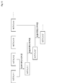
図16は、共通ランドマーク設定部の機能ブロック図であり、
図17は、フローチャート(その3)であり、
図18は、ランドマーク間ベクトルを示す図(その1)であり、
図19は、ランドマーク間ベクトルを示す図(その2)であり、
図20は、共通ランドマークを設定する態様を示す図であり、
図21は、ランドマーク間ベクトルを示す図(その3)であり、
図22は、ランドマーク間ベクトルを示す図(その4)であり、
図23は、共通ランドマークを設定する態様を示す図であり、
図24は、共通ランドマークを設定する処理を説明する図(その1)であり、
図25は、共通ランドマークを設定する処理を説明する図(その2)であり、
図26は、共通ランドマークを設定する処理を説明する図(その3)であり、
図27は、共通ランドマークを設定する処理を説明する図(その4)であり、
図28は、フローチャート(その4)であり、
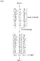
図29は、区画線を設定する処理を説明する図(その1)であり、
図30は、区画線を設定する処理を説明する図(その2)であり、
図31は、区画線を設定する処理を説明する図(その3)である。
以下、一実施形態について図面を参照して説明する。図1に示すように、地図生成システム1は、車両側に搭載されている車載機2と、ネットワーク側に配置されているサーバ3(地図生成装置に相当する)とがデータ通信可能に構成されている。車載機2とサーバ3とは複数対一の関係にあり、サーバ3は複数の車載機2との間でデータ通信可能である。
車載機2は、制御部4と、データ通信部5と、画像データ入力部6と、記憶装置7とを備え、各機能ブロックが内部バス8を介してデータ通信可能に構成されている。制御部4は、CPU(Central Processing Unit)、ROM(Read Only Memory)、RAM(Random Access Memory)及びI/O(Input/Output)を有するマイクロコンピュータにより構成されている。マイクロコンピュータは、非遷移的実体的記憶媒体に格納されているコンピュータプログラムを実行することで、コンピュータプログラムに対応する処理を実行し、車載機2の動作全般を制御する。
データ通信部5は、サーバ3との間のデータ通信を制御する。車載カメラ9は、車載機2とは別体に設けられており、車両前方を撮影し、その撮影した画像データを車載機2に出力する。画像データ入力部6は、車載カメラ9から画像データを入力すると、その入力した画像データを制御部4に出力する。制御部4は、GPS(Global Positioning System)受信機により受信されたGPS信号を用いて測位された車両位置と、その車両位置が測位された時刻と、車載カメラ9から入力した画像データから生成されたセグメントとを含むデータをプローブデータとして定期的に記憶装置7に記憶させる。制御部4は、例えば所定時間が経過する毎や車両の走行距離が所定距離に到達する毎に記憶装置7からプローブデータを読出し、その読出したプローブデータをデータ通信部5からサーバ3に送信させる。尚、本実施形態では、車載カメラ9により撮影された画像データからセグメントが生成される場合を例示しているが、車載カメラ9とは別の測定機器により取得された測量データからセグメントが生成されても良い。又、画像データと測量データとが併用され、画像データと測量データとからセグメントが生成されても良い。
サーバ3は、制御部10と、データ通信部11と、記憶装置12とを備え、各機能ブロックが内部バス13を介してデータ通信可能に構成されている。制御部10は、CPU、ROM、RAM及びI/Oを有するマイクロコンピュータにより構成されている。マイクロコンピュータは、非遷移的実体的記憶媒体に格納されているコンピュータプログラムを実行することで、コンピュータプログラムに対応する処理を実行し、サーバ3の動作全般を制御する。マイクロコンピュータが実行するコンピュータプログラムには地図生成プログラムが含まれる。
データ通信部11は、車載機2との間のデータ通信を制御する。記憶装置12は、プローブデータを記憶するプローブデータ記憶部12aと、地図データを記憶する地図データ記憶部12bとを備える。制御部10は、車載機2からプローブデータがデータ通信部11により受信されると、その受信されたプローブデータをプローブデータ記憶部12aに記憶させる。即ち、車載機2とサーバ3とが複数対一の関係にあるので、制御部10は、複数の車載機2から受信された複数のプローブデータをプローブデータ記憶部12aに記憶させる。又、制御部10は、後述するように地図データを生成すると、その生成した地図データを地図データ記憶部12bに記憶させる。制御部10は、地図データ記憶部12bに記憶されている地図データを読出し、その読出した地図データをデータ通信部11から車載機2に配信させる。
図2に示すように、制御部10は、セグメント取得部10aと、統合ランドマーク設定部10bと、位置補正部10cと、重なり判定部10dと、共通ランドマーク設定部10eと、向き補正部10fと、ランドマーク位置平均化部10gと、サイズ補正部10hと、線形歪み補正部10iと、区画線設定部10jと、地図データ生成部10kと、地図データ配信部10lとを備える。これらの機能のブロックは、マイクロコンピュータが実行する地図生成プログラムの処理に該当する。
セグメント取得部10aは、記憶装置12のプローブデータ記憶部12aに記憶されているプローブデータを読出し、その読出したプローブデータからセグメントを取得する。セグメントは、道路上にペイントされている区画線と、道路上に設置されている標識や看板等の目印を示すランドマークと、車両の走行軌跡とを含む単位である。ここで、セグメント取得部10aは、後述するように共通ランドマークを設定する処理を行う際に共通ランドマークとして設定不能なランドマークが存在することを考慮し、できる限り多くのランドマークが含まれているセグメントを取得するのが望ましい。即ち、セグメント取得部10aは、セグメントに含まれるランドマークの個数を所定個数と比較し、所定個数以上のランドマークが含まれているセグメントを取得対象とし、所定個数以上のランドマークが含まれていないセグメントを取得対象としなくても良い。又、セグメント取得部10aは、ランドマークの検出精度を判定し、検出レベルが所定レベル以上のランドマークが所定個数以上含まれているセグメントを取得対象とし、検出レベルが所定レベル以上のランドマークが所定個数以上含まれていないセグメントを取得対象としなくても良い。
ここで、所定個数や所定レベルは、固定値でも良いし、例えば車両の走行位置や走行環境等に応じて決定する可変値でも良い。即ち、ランドマークの個数が比較的少ない地域を車両が走行中では、所定個数を大きい値で設定すると、取得対象になり得るセグメントが過少になる虞があるので、所定個数を小さい値で設定することが望ましい。これとは反対に、ランドマークの個数が比較的多い地域を車両が走行中では、所定個数を小さい値で設定すると、取得対象になり得るセグメントが過多になる虞があるので、所定個数を大きい値で設定することが望ましい。所定レベルについても同様であり、例えば天候等の影響により検出環境が比較的劣悪な環境下で車両が走行中では、所定レベルを高いレベルで設定すると、取得対象になり得るセグメントが過少になる虞があるので、所定レベルを低いレベルで設定することが望ましい。これとは反対に、検出環境が比較的良好な環境下で車両が走行中では、所定レベルを低いレベルで設定すると、取得対象になり得るセグメントが過多になる虞があるので、所定レベルを高いレベルで設定することが望ましい。
統合ランドマーク設定部10bは、セグメントがセグメント取得部10aにより取得されると、その取得されたセグメント中において複数のランドマークを統合し、統合ランドマークを設定する。
位置補正部10cは、セグメントがセグメント取得部10aにより取得されると、その取得されたセグメントの両端のGPS座標にしたがって当該セグメントの位置を補正する。重なり判定部10dは、セグメントの位置が位置補正部10cにより補正されると、その補正されたセグメントの位置の重なりを判定する。即ち、重なり判定部10dは、セグメントの両端のGPS座標が一致するセグメントが複数存在すると判定すると、それらの複数のセグメントが重なっていると判定する。
共通ランドマーク設定部10eは、セグメントの位置の重なりが重なり判定部10dにより判定されると、その重なりが判定されたセグメント中において他のセグメントと共通する共通ランドマークを設定する。
向き補正部10fは、共通ランドマークが共通ランドマーク設定部10eにより設定されると、その設定された共通ランドマークの位置にしたがってセグメントの向きを補正する。具体的には、向き補正部10fは、共通ランドマークの重心点を計算して平面近似し、その平面に対する法線ベクトルを計算し、重心点の平均を平均重心点として計算すると共に法線ベクトルの平均を平均法線ベクトルとして計算する。向き補正部10fは、セグメントを平均重心点に対して平行移動すると共に平均法線ベクトルに対して回転移動する。向き補正部10fは、共通ランドマークの誤差の二乗和が最小となるようにセグメントを平均法線ベクトル周りに回転移動することで、セグメントの向きを補正する。
ランドマーク位置平均化部10gは、セグメントの向きが向き補正部10fにより補正されると、その向きが補正されたセグメント中においてランドマークの位置を平均化する。サイズ補正部10hは、ランドマークの位置がランドマーク位置平均化部10gにより平均化されると、その平均化されたランドマークの位置にしたがってセグメントのサイズを補正する。線形歪み補正部10iは、ランドマークの位置がランドマーク位置平均化部10gにより平均化されると、その平均化されたランドマークの位置にしたがってセグメントの線形歪みを補正する。
区画線設定部10jは、セグメントのサイズがサイズ補正部10hにより補正され、セグメントの線形歪みが線形歪み補正部10iにより補正されると、そのサイズ及び線形歪みが補正されたセグメント中の区画線を設定する。地図データ生成部10kは、区画線が区画線設定部10jにより設定されると、その設定された区画線を地図上の区画線と特定して地図データを生成する。地図データ配信部10lは、地図データが地図データ生成部10kにより生成されると、その生成された地図データをデータ通信部11から車載機2に配信させる。
次に、上記した構成の作用について図3から図31を参照して説明する。
サーバ3において、制御部10は、地図生成処理を開始すると、記憶装置12のプローブデータ記憶部12aに記憶されている複数のプローブデータを読出し、その読出した複数のプローブデータから複数のセグメントを取得する(S1、セグメント取得手順に相当する)。制御部10は、複数のセグメントを取得すると、その取得した複数のセグメントにおいて統合ランドマークを設定する(S2)。即ち、制御部10は、図5に示すように、例えば道路上に複数の標識A1~A5が並設されている場合に、その並設されている標識A1~A5のランドマークを統合し、図6に示すように、統合ランドマークとして設定する。尚、制御部10は、複数の標識のランドマークを統合することに限らず、複数の看板のランドマークを統合しても良いし、標識のランドマークと看板のランドマークとを混在して統合しても良い。
サーバ3において、制御部10は、地図生成処理を開始すると、記憶装置12のプローブデータ記憶部12aに記憶されている複数のプローブデータを読出し、その読出した複数のプローブデータから複数のセグメントを取得する(S1、セグメント取得手順に相当する)。制御部10は、複数のセグメントを取得すると、その取得した複数のセグメントにおいて統合ランドマークを設定する(S2)。即ち、制御部10は、図5に示すように、例えば道路上に複数の標識A1~A5が並設されている場合に、その並設されている標識A1~A5のランドマークを統合し、図6に示すように、統合ランドマークとして設定する。尚、制御部10は、複数の標識のランドマークを統合することに限らず、複数の看板のランドマークを統合しても良いし、標識のランドマークと看板のランドマークとを混在して統合しても良い。
制御部10は、GPS座標にしたがってセグメントの位置を補正し(S3)、複数のセグメントの位置の重なりを判定する(S4)。複数のセグメントの位置の重なりを判定する処理については補足を後述する。制御部10は、複数のセグメントの位置の重なりを判定すると、共通ランドマークを設定する(S5、共通ランドマーク設定手順に相当する)。即ち、制御部10は、図7に示すように、複数のセグメント間で共通する単独のランドマークや統合ランドマークが存在する場合に、その共通する単独のランドマークや統合ランドマークを共通ランドマークとして設定する。共通ランドマークを設定する処理については補足を後述する。尚、制御部10は、3次元位置を特定することを考慮すると、4個以上の共通ランドマークを設定する必要があり、少なくとも4個の共通ランドマークが同一平面でないことが必要である。又、制御部10は、共通ランドマークをセグメント内で密集した状態よりも散在した状態で設定することが望ましい。
制御部10は、共通ランドマークを設定すると、向き補正処理に移行し(S6)、その設定した共通ランドマークの位置にしたがってセグメントの向きを補正する。即ち、制御部10は、図8に示すように、共通ランドマークの位置にしたがってセグメントの向きを補正する。
制御部10は、向き補正処理を開始すると、図9に示すように、共通ランドマークの重心点を計算して平面近似し(S21)、その平面に対する法線ベクトルを計算する(S22)。制御部10は、図10に示すように、重心点の平均を平均重心点として計算し(S23)、法線ベクトルの平均を平均法線ベクトルとして計算し(S24)、セグメントを平均重心点に対して平行移動し(S25)、平均法線ベクトルに対して回転移動する(S26)。制御部10は、図11に示すように、共通ランドマークの誤差の二乗和が最小となるようにセグメントを平均法線ベクトル周りに回転移動し(S27)、向き補正処理を終了する。制御部10は、向き補正処理を終了することで、図12に示すように、向きを補正したセグメントを取得する。
制御部10は、向き補正処理を終了すると、図13に示すように、ランドマークの位置を平均化する(S7)。制御部10は、ランドマークの位置を平均化すると、取得した全てのセグメントを処理済みであるか否かを判定する(S8)。制御部10は、取得した全てのセグメントを処理済みでなく、未処理のセグメントが存在すると判定すると(S8:NO)、ステップS4に戻り、ステップS4以降を繰り返す。制御部10は、取得した全てのセグメントを処理済みであり、未処理のセグメントが存在しないと判定すると(S8:YES)、その平均化したランドマークの位置にしたがってセグメントのサイズ及び線形歪みを補正する(S9)。
制御部10は、セグメントのサイズ及び線形歪みを補正すると、図14に示すように、区画線を設定する(S10、区画線設定手順に相当する)。区画線を設定する処理については補足を後述する。制御部10は、区画線を設定すると、その設定した区画線を地図上の区画線と特定して地図データを生成し(S11、地図生成手順に相当する)、地図生成処理を終了する。
これ以降、制御部10は、このようにして生成した地図データを記憶装置12の地図データ記憶部12bに記憶させる。又、制御部10は、地図データ記憶部12bに記憶されている地図データを読出し、その読出した地図データをデータ通信部11から車載機2に配信させる。尚、制御部10が地図データを配信させる条件はどのような条件であっても良く、例えば地図データの配信要求が受信された場合に当該地図データの配信要求を送信した車載機2に配信させても良いし、不特定多数の車載機2に定期的に配信させても良い。
上記した複数のセグメントの位置の重なりを判定する処理(S4)について図15を参照して補足する。制御部10は、図15に示すように、例えば複数のセグメントとしてセグメント1~4を取得すると、最初にセグメント1とセグメント2とについて位置の重なりを判定し、セグメント1とセグメント2とから生成したセグメント1´においてランドマークの位置を平均化する(S7)。制御部10は、未処理のセグメントとしてセグメント3が存在すると判定すると(S8:NO)、続いてセグメント1´とセグメント3とについて位置の重なりを判定し、セグメント1´とセグメント3とから生成したセグメント2´においてランドマークの位置を平均化する(S7)。制御部10は、未処理のセグメントとしてセグメント4が存在すると判定すると(S8:NO)、続いてセグメント2´とセグメント4とについて位置の重なりを判定し、セグメント2とセグメント4とから生成したセグメント3´においてランドマークの位置を平均化する(S7)。これ以降、制御部10は、取得した複数の全てのセグメントを処理し、未処理のセグメントが存在しないと判定するまで上記した処理を繰り返す。
次に、上記した共通ランドマークを設定する処理(S5)について図16から図27を参照して補足する。ここでは、複数のセグメントとしてセグメント1及びセグメント2を取得した場合を説明する。セグメント1とセグメント2とは略同一の領域であり、セグメント1のランドマーク1~5(図18参照)とセグメント2のランドマーク1~5(図19参照)とは同一のランドマークである。ランドマーク1~5は、セグメント1とセグメント2との両方に含まれるが、ランドマーク6は、セグメント1のみに含まれる。ランドマーク1~6は、単独のランドマーク及び統合ランドマークのうち何れであっても良い。
制御部10において、共通ランドマーク設定部10eは、複数のランドマークの分布をパターンマッチングし、共通ランドマークを設定する。共通ランドマーク設定部10eは、図16に示すように、基準ランドマーク設定部21aと、ランドマーク間ベクトル算出部21bと、候補設定部21cと、設定部21dとを有する。
基準ランドマーク設定部21aは、セグメントに含まれる複数のランドマークのうち何れかを基準ランドマークとして設定する。ランドマーク間ベクトル算出部21bは、基準ランドマークが基準ランドマーク設定部21aにより設定されると、基準ランドマークとして設定されなかった残りの全てのランドマークに対し、基準ランドマークとして設定されたランドマークからの相対距離及び方向を算出し、ランドマーク間ベクトルを算出する。
候補設定部21cは、セグメント1に含まれるランドマークに対してランドマーク間ベクトルがランドマーク間ベクトル算出部21bにより算出され、セグメント2に含まれるランドマークに対してランドマーク間ベクトルがランドマーク間ベクトル算出部21bにより算出されると、それら算出されたランドマーク間ベクトルを比較して共通ランドマーク候補を設定する。
設定部21dは、一の基準ランドマークに対して一の共通ランドマーク候補が候補設定部21cにより設定され、他の基準ランドマークに対して他の共通ランドマーク候補が候補設定部21cにより設定されると、それら設定された一の共通ランドマーク候補と他の共通ランドマーク候補とを比較して共通ランドマークを設定する。
以下、具体的に図17から図27を参照して説明する。制御部10は、セグメント1において基準ランドマークを設定し(S31、基準ランドマーク設定手順に相当する)、ランドマーク間ベクトルを算出する(S32、ランドマーク間ベクトル算出手順に相当する)。即ち、制御部10は、図18に示すように、セグメント1においてランドマーク1~6のうち例えばランドマーク1を基準ランドマークとして設定する。制御部10は、基準ランドマークとして設定しなかった残りの全てのランドマーク2~6について、その基準ランドマークとして設定したランドマーク1からの相対距離及び方向を算出し、ランドマーク間ベクトルを算出する。
制御部10は、セグメント2において基準ランドマークを設定し(S33、基準ランドマーク設定手順に相当する)、ランドマーク間ベクトルを算出する(S34、ランドマーク間ベクトル算出手順に相当する)。即ち、制御部10は、図19に示すように、セグメント2においてランドマーク1~5のうちセグメント1と同じく例えばランドマーク1を基準ランドマークとして設定する。制御部10は、基準ランドマークとして設定しなかった残りの全てのランドマーク2~5に対し、その基準ランドマークとして設定したランドマーク1からの相対距離及び方向を算出し、ランドマーク間ベクトルを算出する。
制御部10は、セグメント1とセグメント2におけるランドマークの分布に基づいて共通ランドマーク候補を設定する(S35、候補設定手順に相当する)。即ち、制御部10は、図20に示すように、基準ランドマークであるランドマーク1を基準とし、セグメント1のランドマークに対して算出したランドマーク間ベクトルと、セグメント2のランドマークに対して算出したランドマーク間ベクトルとを比較して誤差を判定する。制御部10は、例えばセグメント1のランドマークに対して算出したランドマーク間ベクトルを基準とする場合であれば、セグメント1のランドマーク2~6の位置を中心とする円形状の誤差範囲を、ランドマーク間ベクトルの大きさに基づいて設定する。制御部10は、ランドマーク間ベクトルの大きさが相対的に大きければ、誤差範囲を相対的に大きく設定し、ランドマーク間ベクトルの大きさが相対的に小さければ、誤差範囲を相対的に小さく設定する。
制御部10は、セグメント1のランドマーク2~6の位置を中心とする円形状の誤差範囲を設定すると、その設定した誤差範囲内にセグメント2のランドマーク2~5が存在するか否かを判定する。図20の例示では、制御部10は、例えばセグメント2のランドマーク2,4,5については、それぞれセグメント1のランドマーク2,4,5の位置を中心とする円形状の誤差範囲内に存在すると判定するが、セグメント2のランドマーク3については、セグメント1のランドマーク3の位置を中心とする円形状の誤差範囲内に存在しないと判定する。
制御部10は、セグメント2のランドマーク2~5の全てについて誤差範囲内に存在するか否かを判定し、基準ランドマークして設定したランドマークと、誤差範囲内に存在するランドマークとを共通ランドマーク候補として設定する。図20の例示では、制御部10は、基準ランドマークして設定したランドマーク1と、誤差範囲内に存在するランドマーク2,4,5とを共通ランドマーク候補として設定する。制御部10は、誤差範囲内に存在しないランドマーク3を共通ランドマーク候補から外し、セグメント1に存在するがセグメント2に存在しないランドマーク6も共通ランドマーク候補から外す。尚、以上は、セグメント1のランドマークに対して算出したランドマーク間ベクトルを基準とする場合を説明したが、セグメント2のランドマークに対して算出したランドマーク間ベクトルを基準としても良い。制御部2は、セグメント2のランドマークに対して算出したランドマーク間ベクトルを基準とする場合でも、ランドマーク1,2,4,5を共通ランドマーク候補として設定することになる。
制御部10は、セグメント1及びセグメント2について、基準ランドマークを変更し、上記した処理を繰り返す。制御部10は、セグメント1において別の基準ランドマークを設定し(S36、基準ランドマーク設定手順に相当する)、ランドマーク間ベクトルを算出する(S37、ランドマーク間ベクトル算出手順に相当する)。即ち、制御部10は、図21に示すように、セグメント1においてランドマーク1~6のうち例えばランドマーク5を基準ランドマークとして設定する。制御部10は、基準ランドマークとして設定しなかった残りの全てのランドマーク1~4,6に対し、その基準ランドマークとして設定したランドマーク5からの相対距離及び方向を算出し、ランドマーク間ベクトルを算出する。
制御部10は、セグメント2において別の基準ランドマークを設定し(S38、基準ランドマーク設定手順に相当する)、ランドマーク間ベクトルを算出する(S39、ランドマーク間ベクトル算出手順に相当する)。即ち、制御部10は、図22に示すように、セグメント2においてランドマーク1~5のうちセグメント1と同じく例えばランドマーク5を基準ランドマークとして設定する。制御部10は、基準ランドマークとして設定しなかった残りの全てのランドマーク1~4について、その基準ランドマークとして設定したランドマーク5からの相対距離及び方向を算出し、ランドマーク間ベクトルを算出する
制御部10は、セグメント1とセグメント2におけるランドマークの分布に基づいて共通ランドマーク候補を設定する(S40、候補設定手順に相当する)。即ち、制御部10は、図23に示すように、基準ランドマークであるランドマーク5を基準とし、セグメント1のランドマークに対して算出したランドマーク間ベクトルとセグメント2のランドマークに対して算出したランドマーク間ベクトルとを比較して誤差を判定する。制御部10は、例えばセグメント1のランドマークに対して算出したランドマーク間ベクトルを基準とする場合であれば、セグメント1のランドマーク1~4,6の位置を中心とする円形状の誤差範囲を、ランドマーク間ベクトルの大きさに基づいて設定する。この場合も、制御部10は、ランドマーク間ベクトルの大きさが相対的に大きければ、誤差範囲を相対的に大きく設定し、ランドマーク間ベクトルの大きさが相対的に小さければ、誤差範囲を相対的に小さく設定する。
制御部10は、セグメント1のランドマーク1~4,6の位置を中心とする円形状の誤差範囲を設定すると、その設定した誤差範囲内にセグメント2のランドマーク1~4が存在するか否かを判定する。図23の例示では、制御部10は、例えばセグメント2のランドマーク1,2,4については、それぞれセグメント1のランドマーク1,2,4の位置を中心とする円形状の誤差範囲内に存在すると判定するが、セグメント2のランドマーク3については、セグメント1のランドマーク3の位置を中心とする円形状の誤差範囲内に存在しないと判定する。
制御部10は、セグメント2のランドマーク1~4の全てについて誤差範囲内に存在するか否かを判定し、基準ランドマークして設定したランドマークと、誤差範囲内に存在するランドマークとを共通ランドマーク候補として設定する。図23の例示では、制御部10は、基準ランドマークして設定したランドマーク5と、誤差範囲内に存在するランドマーク1,2,4とを共通ランドマーク候補として設定する。制御部10は、誤差範囲内に存在しないランドマーク3を共通ランドマーク候補から外し、セグメント1に存在するがセグメント2に存在しないランドマーク6も共通ランドマーク候補から外す。この場合も、セグメント1のランドマークに対して算出したランドマーク間ベクトルを基準とする場合を説明したが、セグメント2のランドマークに対して算出したランドマーク間ベクトルを基準としても良い。制御部2は、セグメント2のランドマークに対して算出したランドマーク間ベクトルを基準とする場合でも、ランドマーク1,2,4,5とを共通ランドマーク候補として設定することになる。
制御部10は、このようにしてランドマーク1を基準ランドマークとしたときの共通ランドマーク候補を設定し、ランドマーク5を基準ランドマークとしたときの共通ランドマーク候補を設定すると、両者が一致するか否かを判定する(S41)。制御部10は、例えばランドマーク1を基準ランドマークとしたときの共通ランドマーク候補とランドマーク5を基準ランドマークとしたときの共通ランドマーク候補とが完全に一致したことを条件として両者が一致すると判定する。尚、制御部10は、比較対象とする共通ランドマーク候補の個数が相対的に少なければ、完全に一致したことを条件とし、比較対象とする共通ランドマーク候補の個数が相対的に多ければ、完全に一致したことを条件とする代わりに、一致率が所定割合以上であることを条件としても良い。
制御部10は、両者が一致すると判定すると(S41:YES)、共通ランドマーク候補を共通ランドマークとして設定する(S42、設定手順に相当する)。図20及び図23の例示では、制御部10は、ランドマーク1を基準ランドマークとしたときの共通ランドマーク候補がランドマーク1,2,4,5であり、ランドマーク5を基準ランドマークとしたときの共通ランドマーク候補もランドマーク1,2,4,5であり、両者が一致するので、図24に示すように、一致した共通ランドマーク候補であるランドマーク1,2,4,5を共通ランドマークとして設定する。
制御部10は、両者が一致しないと判定すると(S41:NO)、ステップS36に戻り、ステップS36以降を繰り返す。即ち、制御部10は、セグメント1及びセグメント2について基準ランドマークを変更し、上記した処理を繰り返す。即ち、制御部10は、ランドマーク1~5のうちランドマーク1,5以外のランドマーク2~4を基準ランドマークとして設定する。
制御部10は、例えばランドマーク1を基準ランドマークとしたときの共通ランドマーク候補がランドマーク1,2,4,5であり、ランドマーク5を基準ランドマークとしたときの共通ランドマーク候補がランドマーク1,2,3,5であると判定すると、セグメント1及びセグメント2について基準ランドマークを変更し、例えばランドマーク2を基準ランドマークとして設定し、共通ランドマーク候補を設定する。
制御部10は、ランドマーク2を基準ランドマークとしたときの共通ランドマーク候補がランドマーク1,2,4,5であると判定すると、ランドマーク1を基準ランドマークとしたときの共通ランドマーク候補と、ランドマーク2を基準ランドマークとしたときの共通ランドマーク候補とが一致するので、図25に示すように、その一致した共通ランドマーク候補であるランドマーク1,2,4,5を共通ランドマークとして設定する。
又、制御部10は、ランドマーク2を基準ランドマークとしたときの共通ランドマーク候補がランドマーク1,2,3,5であると判定すると、ランドマーク5を基準ランドマークとしたときの共通ランドマーク候補と、ランドマーク2を基準ランドマークとしたときの共通ランドマーク候補とが一致するので、図26に示すように、その一致した共通ランドマーク候補であるランドマーク1,2,3,5を共通ランドマークとして設定する。
尚、以上は、2つの基準ランドマークにおいて共通ランドマーク候補が一致した場合に、その一致した共通ランドマーク候補で共通ランドマークとして設定する構成を説明したが、3つ以上の基準ランドマークにおいて共通ランドマーク候補が一致した場合に、その一致した共通ランドマーク候補で共通ランドマークとして設定する構成でも良い。制御部10は、図27に示すように、例えばランドマーク1を基準ランドマークとしたときの共通ランドマーク候補がランドマーク1,2,4,5であり、ランドマーク5を基準ランドマークとしたときの共通ランドマーク候補がランドマーク1,2,4,5であり、ランドマーク2を基準ランドマークとしたときの共通ランドマーク候補がランドマーク1,2,4,5であると判定すると、その一致した共通ランドマーク候補であるランドマーク1,2,4,5を共通ランドマークとして設定する構成でも良い。即ち、共通ランドマークを設定する条件とする基準ランドマークを変更する回数に任意として良く、その回数を多くすることで、正確性を高めることができる。
次に、上記した区画線を設定する処理(S10)について図28から図31を参照して補足する。制御部10は、初期値kを分割数に設定し(S51)、区画線になり得る点群をk-mean法でクラスタ分割し、分割線を設定する(S52)。即ち、制御部10は、図29及び図30に示すように、初期値kを分割数に設定し、区画線になり得る点群をk-mean法でクラスタ分割し、分割線を設定する。制御部10は、隣接する分割線同士の距離をクラスタ平均間の距離として計算し(S53)、その計算したクラスタ平均間の距離と設定距離とを比較し、全てのクラスタ平均間の距離が設定距離以上であるか否かを判定する(S54)。制御部10は、全てのクラスタ平均間の距離が設定距離以上でないと判定すると(S54:NO)、分割数を減算し(S55)、ステップS52に戻り、ステップS52以降を繰り返す。
制御部10は、全てのクラスタ平均間の距離が設定距離以上であると判定すると(S54:YES)、区画線候補を特定し(S56)、その特定した区画線候補に対してクラスタ番号を割り当てる(S57)。制御部10は、クラスタ番号を割り当てると、図31に示すように、点群の最大位置及び最小位置を取得し(S58)、最大位置に対応する最大位置線と、最小位置に対応する最小位置線と、その最大位置線から最小位置線までの範囲をクラスタ数で等分する等分線を算出する(S59)。制御部10は、その算出した最大位置線、最小位置線、等分線の隣接する線同士の中心線を算出し、その算出した中心線を区画線として設定する(S60)。
以上に説明したように本実施形態によれば、次に示す作用効果を得ることができる。
サーバ3において、車載カメラ9により撮影されたカメラ画像から生成されたセグメント中において他のセグメントと共通する共通ランドマークを用いてセグメント中の区画線を設定し、その設定したセグメント中の区画線を地図上の区画線と特定して地図データを生成するようにした。ばらつきが大きいGPS座標を用いるのではなく、共通ランドマークを用いてセグメント中の区画線を設定し、その平均化した区画線を地図上の区画線と特定することで、少ないサンプル数でも精度の高い地図を適切に生成することができる。
サーバ3において、車載カメラ9により撮影されたカメラ画像から生成されたセグメント中において他のセグメントと共通する共通ランドマークを用いてセグメント中の区画線を設定し、その設定したセグメント中の区画線を地図上の区画線と特定して地図データを生成するようにした。ばらつきが大きいGPS座標を用いるのではなく、共通ランドマークを用いてセグメント中の区画線を設定し、その平均化した区画線を地図上の区画線と特定することで、少ないサンプル数でも精度の高い地図を適切に生成することができる。
又、サーバ3において、複数のランドマークの分布をパターンマッチングし、共通ランドマークを設定するようにした。パターンマッチングの手法を行うことで、共通ランドマークを設定することができる。
又、サーバ3において、セグメント中において複数のランドマークを統合した統合ランドマークを設定し、単独のランドマークを用いるだけでなく統合ランドマークも用いて共通ランドマークを設定するようにした。統合ランドマークを用いることで、共通ランドマークを設定する精度を高めることができ、異なるランドマークを共通ランドマークとして誤って設定してしまう事態を未然に回避することができる。
又、サーバ3において、セグメントの位置を補正し、セグメントの位置の重なりを判定し、その判定結果にしたがって共通ランドマークを設定するようにした。セグメントの位置を補正し、セグメントの位置の重なりを判定することで、共通ランドマークを設定する精度を高めることができ、異なるランドマークを共通ランドマークとして誤って設定してしまう事態を未然に回避することができる。
又、サーバ3において、共通ランドマークの位置にしたがってセグメントの向きを補正するようにした。共通ランドマークの位置を用いることで、セグメントの向きを適切に補正することができる。
又、サーバ3において、セグメント中においてランドマークの位置を平均化し、その平均化したランドマークの位置にしたがってセグメントのサイズを補正するようにした。ランドマークの位置を平均化することで、セグメントのサイズを適切に補正することができる。
又、サーバ3において、セグメント中においてランドマークの位置を平均化し、その平均化したランドマークの位置にしたがってセグメントの線形歪みを補正するようにした。ランドマークの位置を平均化することで、セグメントの線形歪みを適切に補正することができる。
又、サーバ3において、地図データを車載機2に配信するようにした。地図データを車載機2に配信することで、車載機2において、サーバ3から配信された精度の高い地図データを用いて車両制御を適切に行うことができる。
本開示は、実施例に準拠して記述されたが、当該実施例や構造に限定されるものではないと理解される。本開示は、様々な変形例や均等範囲内の変形をも包含する。加えて、様々な組み合わせや形態、更には、それらに一要素のみ、それ以上、或いはそれ以下を含む他の組み合わせや形態をも、本開示の範疇や思想範囲に入るものである。
車載機2において、例えば所定時間が経過する毎や車両の走行距離が所定距離に到達する毎に、セグメントを含むプローブデータをサーバ3に送信する構成を例示したが、セグメントに含まれるランドマークの検出数を判定し、ランドマークの検出数が所定値以上であれば、セグメントを含むプローブデータをサーバ3に送信するが、ランドマークの検出数が所定値以上でなければ、セグメントを含むプローブデータをサーバ3に送信しない構成としても良い。即ち、例えば先行車両の存在等によりランドマークの検出数が所定値以上でない場合もあり、ランドマークの検出数が所定値以上でないセグメントを含むプローブデータをサーバ3に送信しても、そのプローブデータをサーバ3が処理対象とせずに破棄することが想定される場合には、そのプローブデータをサーバ3に送信しない構成としても良い。サーバ3にとって不必要なプローブデータを車載機2から送信しないことで、通信コストを低減することができ、ネットワークの負荷を低減することができる。
本開示に記載の制御部及びその手法は、コンピュータプログラムにより具体化された一つ乃至は複数の機能を実行するようにプログラムされたプロセッサ及びメモリを構成することにより提供された専用コンピュータにより実現されても良い。或いは、本開示に記載の制御部及びその手法は、一つ以上の専用ハードウェア論理回路によりプロセッサを構成することにより提供された専用コンピュータにより実現されても良い。若しくは、本開示に記載の制御部及びその手法は、一つ乃至は複数の機能を実行するようにプログラムされたプロセッサ及びメモリと一つ以上のハードウェア論理回路により構成されたプロセッサとの組み合わせにより構成された一つ以上の専用コンピュータにより実現されても良い。又、コンピュータプログラムは、コンピュータにより実行されるインストラクションとして、コンピュータ読み取り可能な非遷移有形記録媒体に記憶されていても良い。
Claims (13)
- 道路上の区画線とランドマークとを含むセグメントを取得するセグメント取得部(10a)と、
前記セグメント取得部により取得されたセグメント中において他のセグメントと共通する共通ランドマークを設定する共通ランドマーク設定部(10e)と、
前記共通ランドマーク設定部により設定された共通ランドマークを用いてセグメント中の区画線を設定する区画線設定部(10j)と、
前記区画線設定部により設定されたセグメント中の区画線を地図上の区画線と特定して地図データを生成する地図データ生成部(10k)と、を備える地図生成装置。 - 前記共通ランドマーク設定部は、複数のランドマークの分布をパターンマッチングし、共通ランドマークを設定する請求項1に記載した地図生成装置。
- 前記共通ランドマーク設定部は、
セグメントに含まれる複数のランドマークのうち何れかを基準ランドマークとして設定する基準ランドマーク設定部(21a)と、
基準ランドマークとして設定されなかった残りの全てのランドマークに対して基準ランドマークとして設定されたランドマークからの相対距離及び方向を算出し、ランドマーク間ベクトルを算出するランドマーク間ベクトル算出部(21b)と、
一のセグメントに含まれるランドマークに対して算出された一のランドマーク間ベクトルと、他のセグメントに含まれるランドマークに対して算出された他のランドマーク間ベクトルとを用いて共通ランドマーク候補を設定する候補設定部(21c)と、
一の基準ランドマークに対して設定された一の共通ランドマーク候補と、他の基準ランドマークに対して設定された他の共通ランドマーク候補とを用いて共通ランドマークを設定する設定部(21d)と、を備える請求項2に記載した地図生成装置。 - 前記セグメント取得部により取得されたセグメント中において複数のランドマークを統合した統合ランドマークを設定する統合ランドマーク設定部(10b)を備え、
前記共通ランドマーク設定部は、前記統合ランドマーク設定部により設定された統合ランドマークを用いて共通ランドマークを設定する請求項1から3の何れか一項に記載した地図生成装置。 - 前記セグメント取得部により取得されたセグメントの位置を補正する位置補正部(10c)と、
前記位置補正部により補正されたセグメントの位置の重なりを判定する重なり判定部(10d)と、を備え、
前記共通ランドマーク設定部は、前記重なり判定部の判定結果にしたがって共通ランドマークを設定する請求項1から4の何れか一項に記載した地図生成装置。 - 前記共通ランドマーク設定部により設定された共通ランドマークの位置にしたがってセグメントの向きを補正する向き補正部(10f)を備える請求項1から5の何れか一項に記載した地図生成装置。
- 前記向き補正部は、共通ランドマークの重心点を計算して平面近似し、その平面に対する法線ベクトルを計算し、重心点の平均を平均重心点として計算すると共に法線ベクトルの平均を平均法線ベクトルとして計算し、セグメントを平均重心点に対して平行移動すると共に平均法線ベクトルに対して回転移動し、共通ランドマークの誤差の二乗和が最小となるようにセグメントを平均法線ベクトル周りに回転移動することで、セグメントの向きを補正する請求項6に記載した地図生成装置。
- セグメント中においてランドマークの位置を平均化するランドマーク位置平均化部(10g)と、
前記ランドマーク位置平均化部により平均化されたランドマークの位置にしたがってセグメントのサイズを補正するサイズ補正部(10h)と、を備える請求項1から7の何れか一項に記載した地図生成装置。 - ランドマークの位置を平均化するランドマーク位置平均化部(10g)と、
前記ランドマーク位置平均化部により平均化されたランドマークの位置にしたがってセグメントの線形歪みを補正する線形歪み補正部(10i)と、を備える請求項1から7の何れか一項に記載した地図生成装置。 - 前記地図データ生成部により生成された地図データを配信する地図データ配信部(10l)を備える請求項1から9の何れか一項に記載した地図生成装置。
- セグメントに含まれる複数のランドマークのうち何れかを基準ランドマークとして設定する基準ランドマーク設定部(21a)と、
基準ランドマークとして設定されなかった残りの全てのランドマークに対し、基準ランドマークとして設定されたランドマークからの相対距離及び方向を算出し、ランドマーク間ベクトルを算出するランドマーク間ベクトル算出部(21b)と、
一のセグメントに含まれるランドマークに対して算出されたランドマーク間ベクトルと、他のセグメントに含まれるランドマークに対して算出されたランドマーク間ベクトルとを用いて、共通ランドマーク候補を設定する候補設定部(21c)と、
一の基準ランドマークに対して設定された一の共通ランドマーク候補と、他の基準ランドマークに対して設定された他の共通ランドマーク候補とを用いて、共通ランドマークを設定する設定部(21d)と、を備える地図生成装置。 - 地図データを生成する地図生成装置(3)の制御部(10)に、
道路上の区画線とランドマークとを含むセグメントを取得するセグメント取得手順と、
前記セグメント取得手順により取得したセグメント中において他のセグメントと共通する共通ランドマークを設定する共通ランドマーク設定手順と、
前記共通ランドマーク設定手順により設定した共通ランドマークを用いてセグメント中の区画線を設定する区画線設定手順と、
前記区画線設定部により設定したセグメント中の区画線を地図上の区画線と特定して地図データを生成する地図生成手順と、を実行させる地図生成プログラム。 - セグメントに含まれる複数のランドマークのうち何れかを基準ランドマークとして設定する基準ランドマーク設定手順と、
基準ランドマークとして設定しなかった残りの全てのランドマークに対し、基準ランドマークとして設定したランドマークからの相対距離及び方向を算出し、ランドマーク間ベクトルを算出するランドマーク間ベクトル算出手順と、
一のセグメントに含まれるランドマークに対して算出したランドマーク間ベクトルと、他のセグメントに含まれるランドマークに対して算出したランドマーク間ベクトルとを用いて、共通ランドマーク候補を設定する候補設定手順と、
一の基準ランドマークに対して設定した一の共通ランドマーク候補と、他の基準ランドマークに対して設定した他の共通ランドマーク候補とを用いて、共通ランドマークを設定する設定手順と、を実行させる地図生成プログラム。
Priority Applications (3)
| Application Number | Priority Date | Filing Date | Title |
|---|---|---|---|
| DE112019004266.1T DE112019004266T5 (de) | 2018-08-31 | 2019-08-22 | Kartenerzeugungsvorrichtung und kartenerzeugungsprogramm |
| CN201980055965.1A CN112639916B (zh) | 2018-08-31 | 2019-08-22 | 地图生成方法以及地图生成装置 |
| US17/186,926 US12078508B2 (en) | 2018-08-31 | 2021-02-26 | Method for generating map and map generation device |
Applications Claiming Priority (4)
| Application Number | Priority Date | Filing Date | Title |
|---|---|---|---|
| JP2018163076 | 2018-08-31 | ||
| JP2018-163076 | 2018-08-31 | ||
| JP2019-142255 | 2019-08-01 | ||
| JP2019142255A JP7192704B2 (ja) | 2018-08-31 | 2019-08-01 | 地図生成装置及び地図生成プログラム |
Related Child Applications (1)
| Application Number | Title | Priority Date | Filing Date |
|---|---|---|---|
| US17/186,926 Continuation US12078508B2 (en) | 2018-08-31 | 2021-02-26 | Method for generating map and map generation device |
Publications (1)
| Publication Number | Publication Date |
|---|---|
| WO2020045232A1 true WO2020045232A1 (ja) | 2020-03-05 |
Family
ID=69645270
Family Applications (1)
| Application Number | Title | Priority Date | Filing Date |
|---|---|---|---|
| PCT/JP2019/032846 Ceased WO2020045232A1 (ja) | 2018-08-31 | 2019-08-22 | 地図生成装置及び地図生成プログラム |
Country Status (1)
| Country | Link |
|---|---|
| WO (1) | WO2020045232A1 (ja) |
Cited By (1)
| Publication number | Priority date | Publication date | Assignee | Title |
|---|---|---|---|---|
| CN115335887A (zh) * | 2020-03-25 | 2022-11-11 | 株式会社电装 | 地图更新装置以及地图更新程序 |
Citations (4)
| Publication number | Priority date | Publication date | Assignee | Title |
|---|---|---|---|---|
| JP2007164636A (ja) * | 2005-12-15 | 2007-06-28 | Toyota Motor Corp | 道路区画線検出装置 |
| JP2013152383A (ja) * | 2012-01-26 | 2013-08-08 | Mitsubishi Electric Corp | 簡略地図生成装置、簡略地図生成方法、簡略地図表示装置、及び簡略地図表示方法 |
| JP2016014647A (ja) * | 2014-06-30 | 2016-01-28 | 現代自動車株式会社Hyundaimotor Company | 自車位置認識装置及び方法 |
| US20180023960A1 (en) * | 2016-07-21 | 2018-01-25 | Mobileye Vision Technologies Ltd. | Distributing a crowdsourced sparse map for autonomous vehicle navigation |
-
2019
- 2019-08-22 WO PCT/JP2019/032846 patent/WO2020045232A1/ja not_active Ceased
Patent Citations (4)
| Publication number | Priority date | Publication date | Assignee | Title |
|---|---|---|---|---|
| JP2007164636A (ja) * | 2005-12-15 | 2007-06-28 | Toyota Motor Corp | 道路区画線検出装置 |
| JP2013152383A (ja) * | 2012-01-26 | 2013-08-08 | Mitsubishi Electric Corp | 簡略地図生成装置、簡略地図生成方法、簡略地図表示装置、及び簡略地図表示方法 |
| JP2016014647A (ja) * | 2014-06-30 | 2016-01-28 | 現代自動車株式会社Hyundaimotor Company | 自車位置認識装置及び方法 |
| US20180023960A1 (en) * | 2016-07-21 | 2018-01-25 | Mobileye Vision Technologies Ltd. | Distributing a crowdsourced sparse map for autonomous vehicle navigation |
Cited By (1)
| Publication number | Priority date | Publication date | Assignee | Title |
|---|---|---|---|---|
| CN115335887A (zh) * | 2020-03-25 | 2022-11-11 | 株式会社电装 | 地图更新装置以及地图更新程序 |
Similar Documents
| Publication | Publication Date | Title |
|---|---|---|
| US9952597B2 (en) | Apparatus for correcting vehicle location | |
| US9897454B2 (en) | Host-vehicle-travel-position specification apparatus and host-vehicle-travel-position specification program product | |
| JP6142707B2 (ja) | 車両位置補正装置 | |
| US8892331B2 (en) | Drive assist system and wireless communication device for vehicle | |
| US20170177958A1 (en) | Target Detection Apparatus and Target Detection Method | |
| US12078508B2 (en) | Method for generating map and map generation device | |
| US12228421B2 (en) | Map update device and storage medium | |
| US20190100199A1 (en) | Course Prediction Method and Course Prediction Device | |
| JP6758160B2 (ja) | 車両位置検出装置、車両位置検出方法及び車両位置検出用コンピュータプログラム | |
| JP2020046411A (ja) | データ構造、記憶装置、端末装置、サーバ装置、制御方法、プログラム及び記憶媒体 | |
| JP2016120882A (ja) | 車両運動パラメータ推定装置 | |
| WO2020045232A1 (ja) | 地図生成装置及び地図生成プログラム | |
| JP2020008462A (ja) | 自車位置推定装置 | |
| JP5593793B2 (ja) | 車両制御装置 | |
| EP3971525B1 (en) | Self-position correction method and self-position correction device | |
| JP2016008939A (ja) | 無線通信装置および無線測位システム | |
| JP7388557B2 (ja) | 地図処理システム及び地図処理プログラム | |
| JP6037351B2 (ja) | 車両画像処理装置および車両画像処理方法 | |
| JP2019045341A (ja) | 車両位置検出方法及び車両位置検出装置 | |
| JP6789440B2 (ja) | 物体同定装置 | |
| RU2781373C1 (ru) | Способ коррекции собственного местоположения и устройство коррекции собственного местоположения | |
| US20260042420A1 (en) | Method and apparatus for passive entry system utilizing vehicle sensor | |
| JP7380886B2 (ja) | 地図処理システム及び地図処理プログラム | |
| JP7764764B2 (ja) | センサ較正装置、および、センサ較正方法 | |
| US20260061992A1 (en) | Automated valet parking system |
Legal Events
| Date | Code | Title | Description |
|---|---|---|---|
| 121 | Ep: the epo has been informed by wipo that ep was designated in this application |
Ref document number: 19855286 Country of ref document: EP Kind code of ref document: A1 |
|
| 122 | Ep: pct application non-entry in european phase |
Ref document number: 19855286 Country of ref document: EP Kind code of ref document: A1 |