WO2020044917A1 - 局部洗浄ノズルおよび局部洗浄装置 - Google Patents
局部洗浄ノズルおよび局部洗浄装置 Download PDFInfo
- Publication number
- WO2020044917A1 WO2020044917A1 PCT/JP2019/029846 JP2019029846W WO2020044917A1 WO 2020044917 A1 WO2020044917 A1 WO 2020044917A1 JP 2019029846 W JP2019029846 W JP 2019029846W WO 2020044917 A1 WO2020044917 A1 WO 2020044917A1
- Authority
- WO
- WIPO (PCT)
- Prior art keywords
- nozzle
- local cleaning
- discharge hole
- water discharge
- cleaning nozzle
- Prior art date
- Legal status (The legal status is an assumption and is not a legal conclusion. Google has not performed a legal analysis and makes no representation as to the accuracy of the status listed.)
- Ceased
Links
Images



Classifications
-
- B—PERFORMING OPERATIONS; TRANSPORTING
- B05—SPRAYING OR ATOMISING IN GENERAL; APPLYING FLUENT MATERIALS TO SURFACES, IN GENERAL
- B05B—SPRAYING APPARATUS; ATOMISING APPARATUS; NOZZLES
- B05B1/00—Nozzles, spray heads or other outlets, with or without auxiliary devices such as valves, heating means
-
- C—CHEMISTRY; METALLURGY
- C04—CEMENTS; CONCRETE; ARTIFICIAL STONE; CERAMICS; REFRACTORIES
- C04B—LIME, MAGNESIA; SLAG; CEMENTS; COMPOSITIONS THEREOF, e.g. MORTARS, CONCRETE OR LIKE BUILDING MATERIALS; ARTIFICIAL STONE; CERAMICS; REFRACTORIES; TREATMENT OF NATURAL STONE
- C04B41/00—After-treatment of mortars, concrete, artificial stone or ceramics; Treatment of natural stone
- C04B41/80—After-treatment of mortars, concrete, artificial stone or ceramics; Treatment of natural stone of only ceramics
- C04B41/81—Coating or impregnation
- C04B41/85—Coating or impregnation with inorganic materials
- C04B41/86—Glazes; Cold glazes
-
- E—FIXED CONSTRUCTIONS
- E03—WATER SUPPLY; SEWERAGE
- E03D—WATER-CLOSETS OR URINALS WITH FLUSHING DEVICES; FLUSHING VALVES THEREFOR
- E03D9/00—Sanitary or other accessories for lavatories ; Devices for cleaning or disinfecting the toilet room or the toilet bowl; Devices for eliminating smells
- E03D9/08—Devices in the bowl producing upwardly-directed sprays; Modifications of the bowl for use with such devices ; Bidets; Combinations of bowls with urinals or bidets; Hot-air or other devices mounted in or on the bowl, urinal or bidet for cleaning or disinfecting
Definitions
- the present invention relates to a local cleaning nozzle and a local cleaning device.
- a resin or stainless steel is generally used as a material for a nozzle of a conventional shower toilet, and technology development such as performing antifouling treatment on the surface thereof has been performed (for example, see Patent Documents 1 and 2). ), In long-term use, the surface may be damaged due to sliding friction caused by nozzle driving or cleaning with a brush or the like. There is a problem that dirt easily accumulates on the scratches on the nozzle, and further, it becomes a hotbed for the propagation of bacteria.
- the present invention has been made in view of the above, and by using a nozzle cover made of a material that does not easily scratch the cleaning nozzle surface in a local cleaning device, the scratches generated due to use and cleaning are reduced, and the cleanliness of the nozzle is reduced.
- the purpose is to improve.
- the present invention is a local cleaning nozzle including a nozzle body (for example, a nozzle body 1 to be described later) and a cylindrical nozzle cover (for example, a nozzle cover 2 to be described later) that stores the nozzle body.
- the nozzle body has a water discharge hole (for example, a water discharge hole 11 described later) for discharging cleaning water, and a water passage (for example, a water passage 12 described later) for supplying cleaning water to the water discharge hole
- the nozzle cover has a communication hole (for example, a communication hole 21 described later) formed at a position corresponding to the water discharge hole and communicating with the water discharge hole, and is formed of a non-metallic inorganic material. For example, a cleaning nozzle 10) described later is provided.
- the nozzle cover is made of a ceramic having at least an outer peripheral surface subjected to a glaze treatment.
- the apparatus further comprises fixing means for fixing the nozzle body to the nozzle cover, and the fixing means is an adhesive.
- the water discharge hole is disposed on a distal end side of the elongated nozzle main body, and an adhesive portion formed by the adhesive is disposed on a base end side of the nozzle main body.
- an adhesive portion formed by the adhesive is disposed on a base end side of the nozzle main body.
- the surface of the nozzle cover at the bonding portion is not subjected to a glaze treatment.
- the adhesive may be a resin potting agent (for example, a resin potting agent 5 described later).
- the resin potting agent is preferably a urethane resin or a silicone resin.
- a seal member for example, a seal member 6 described later arranged around the communication hole inside the nozzle cover is further provided.
- the nozzle cover includes an inner peripheral flat portion (for example, an inner peripheral flat portion 22 described later) formed on at least a part of an inner peripheral surface thereof.
- the nozzle main body has an outer peripheral flat portion (for example, an outer peripheral flat portion 13 described later) formed on at least a part of the outer peripheral surface thereof and in contact with the inner peripheral flat portion.
- the glaze layer (for example, a glaze layer 3 described later) formed by the glaze treatment is a colored glaze containing a coloring pigment, which is arranged in order from the ceramic side. It may be composed of two layers, a layer (for example, a colored glaze layer 31 described later) and a colorless and transparent colorless and transparent glaze layer containing no pigment (for example, a colorless and transparent glaze layer 32 described later).
- the present invention also provides a local cleaning device (for example, a local cleaning device 100 described later), which includes the local cleaning nozzle according to any one of (1) to (10).
- a local cleaning device for example, a local cleaning device 100 described later
- the present invention is also a local cleaning nozzle including a nozzle main body (for example, a nozzle main body 1 described later) and a cylindrical nozzle cover (for example, a nozzle cover 2 described later) for accommodating the nozzle main body.
- the nozzle body has a water discharge hole (for example, a water discharge hole 11 described later) for discharging cleaning water, and a water passage (for example, a water passage 12 described later) for supplying cleaning water to the water discharge hole.
- the nozzle cover has a communication hole (for example, a communication hole 21 described later) formed at a position corresponding to the water discharge hole and communicating with the water discharge hole, and at least the outer peripheral surface is made of a metal base that has been subjected to a glaze treatment.
- a local cleaning nozzle for example, a cleaning nozzle 10 described later).
- the metal is preferably stainless steel.
- the glaze layer (for example, the glaze layer 3 described later) formed by the glaze treatment is a colored layer containing a coloring pigment which is arranged in order from the metal base side. It may be composed of two layers: a glaze layer (for example, a colored glaze layer 31 described later) and a colorless and transparent colorless and transparent glaze layer containing no pigment (for example, a colorless and transparent glaze layer 32 described later).
- the present invention also provides a local cleaning device (for example, a local cleaning device 100 described later) including the local cleaning nozzle according to any one of (12) to (15).
- a local cleaning device for example, a local cleaning device 100 described later
- a nozzle cover made of a material that does not easily damage the cleaning nozzle surface it is possible to prevent the accumulation of dirt and the propagation of bacteria at the damaged portion, and improve the cleanliness of the nozzle.
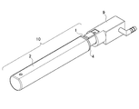
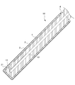
- FIG. 2 is a view showing a cleaning nozzle 10 according to the first embodiment of the present invention. It is a figure showing a section parallel to an axial direction of washing nozzle 10 concerning a 1st embodiment of the present invention.
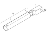
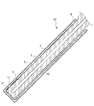
- FIG. 9 is a view showing a cleaning nozzle 20 according to a second embodiment of the present invention. It is a figure showing a section parallel to the direction of an axis of washing nozzle 20 concerning a 2nd embodiment of the present invention. It is a figure showing the section which intersects perpendicularly to the direction of an axis of washing nozzle 20 concerning a 2nd embodiment of the present invention.
- FIG. 1 ist embodiment of the present invention.
- FIG. 2 is a view showing a cleaning nozzle 10 according to the first embodiment of the present invention. It is a figure showing a section parallel to an axial direction of washing nozzle 10 concerning a 1st embodiment of the present invention.
- FIG. 9 is a view showing a cleaning nozzle 20 according to a second embodiment of the present invention
- FIG. 2 is a diagram showing a cross section of a nozzle cover 2 and a glaze layer 3 of the present invention.
- FIG. 9 is a view showing a cleaning nozzle 30 according to a second embodiment of the present invention. It is a figure showing the section which intersects perpendicularly to the direction of an axis of washing nozzle 30 of the present invention.
- FIG. 1 is a diagram showing a local cleaning device 100 according to the first embodiment of the present invention.
- the local cleaning device 100 is attached to an upper portion of a toilet 7 and is used together with the toilet 7 and a toilet seat 8 that supports a user's buttocks.
- the local cleaning device 100 includes a cleaning nozzle 10 housed in a nozzle driving unit 110 and capable of moving back and forth, a water supply valve (not shown) for controlling water supply, and a hot water generation unit (not shown) for heating supply water.
- the hot water is supplied to the cleaning nozzle 10 by heating the flowing water by opening the water supply valve, and the cleaning water is discharged from the water discharge hole 11.
- the cleaning nozzle 10 of the present invention includes a nozzle body 1 and a cylindrical nozzle cover 2, and is attached to the body via a nozzle attachment 9.
- the nozzle body 1 has a water discharge hole 11 for discharging cleaning water, and a water passage 12 for supplying cleaning water to the water discharge hole 11, and a part or all of the nozzle body 2 is stored in the nozzle cover 2.
- the nozzle cover 2 has a communication hole 21 at a position corresponding to the water discharge hole 11, and the nozzle cover 2 is further made of a nonmetallic inorganic material.
- the nozzle body 1 is preferably made of resin. Since high dimensional accuracy can be obtained by resin molding, high aiming accuracy can be obtained when discharging cleaning water.
- the resin used is not particularly limited, and a resin material generally used for a shower toilet nozzle can be used. In the present invention, since the nozzle body 1 is covered and protected by the nozzle cover 2, there is no need to perform an antifouling treatment or the like on the outer surface. . Note that a separate water discharge hole may be attached to the cleaning nozzle 10 via the communication hole 21 of the nozzle cover 2. At this time, it is more preferable to use a member that is hardly damaged by the water discharge hole separate body.
- the nozzle cover 2 is made of a nonmetallic inorganic material having high scratch resistance against sliding friction caused by nozzle driving and cleaning with a brush.
- the outer peripheral surface is made of a glazed pottery material, but is not limited thereto, and may be made of glass, fine ceramics, or the like. Specifically, alumina, zirconia, silicon carbide, silicon nitride, or the like can be used.
- the cylindrical nozzle cover 2 accommodates a part or all of the nozzle body 1 inside to protect it from scratches and dirt.
- the glaze layer 3 formed by the glaze treatment is formed on the outer peripheral surface of the nozzle cover 2 from the viewpoint of improving the cleanliness and appearance of the nozzle cover 2.
- the glaze layer may be transparent, or may include a coloring pigment according to a pottery material serving as a base or a toilet design.
- the means for fixing the nozzle body 1 and the nozzle cover 2 is not particularly limited.
- a preferable means includes an adhesive. According to this method, the fluidity of the adhesive absorbs large dimensional variations of the pottery, and it is possible to perform precise fixing.
- the cleaning nozzle 10 emerges from the distal end of the long cleaning nozzle 10 as the shower toilet is driven, but the adhesive portion 4 formed by the adhesive is disposed only on the base end side.
- the position and the number of the bonding portions 4 are not particularly limited, it is preferable that the bonding portions 4 be kept at positions that are not visible, so that the appearance quality of the nozzle cover can be maintained.
- An adhesive generally used for industrial purposes can be used.
- the surface of the nozzle cover 2 at the bonding portion 4 is not subjected to glaze treatment. Since the glaze treatment is not performed and the unevenness of the ceramic base surface is present, the contact area of the adhesive increases, and the nozzle body 1 and the nozzle cover 2 can be fixed with high adhesive strength.
- FIG. 7 is a diagram showing a layer cross section of the nozzle cover 2 and the glaze layer 3 of the present invention.
- the glaze layer 3 formed by the glaze treatment is composed of two layers, a colored glaze layer 31 containing a colored pigment and a colorless and transparent colorless and transparent glaze layer 32 containing no pigment, which are arranged in this order from the ceramic side. May be done. Thereby, glossiness is obtained while giving the color of the pigment to the cleaning nozzle 10, and the design of the cleaning nozzle 10 and thus the local cleaning device 100 is improved.
- a local cleaning nozzle 10 is a local cleaning nozzle 10 including a nozzle body 1 and a cylindrical nozzle cover 2 that houses the nozzle body 1. It is composed of a non-metallic inorganic material. Thereby, the nozzle main body 1 is protected by the scratch-resistant nozzle cover 2, and the cleanliness of the cleaning nozzle 10 is improved.
- the nozzle cover 2 is made of pottery having at least the outer peripheral surface treated with a glaze. According to this method, the nozzle cover 2 is protected by the glaze layer and has antifouling properties, so that the cleanliness of the cleaning nozzle 10 is improved.
- the glaze layer is not particularly limited, and may be, for example, one that imparts hydrophilicity or water repellency to the nozzle cover 2.
- the local cleaning nozzle 10 further includes fixing means for fixing the nozzle main body 1 to the nozzle cover 2, and the fixing means is an adhesive. According to this method, the fluidity of the adhesive absorbs large dimensional variations of the pottery, and it is possible to perform precise fixing.
- the water discharge hole 11 is disposed on the distal end side of the elongated nozzle main body 1, and the bonding part 4 formed by the adhesive is disposed only on the base end side of the nozzle main body 1. You. The appearance quality of the nozzle cover 2 can be maintained by keeping the bonding portion 4 at a position where it is difficult to see.
- the surface of the nozzle cover 2 at the bonding portion 4 is not subjected to glaze treatment. Since the glaze treatment is not performed and the unevenness of the surface of the pottery as the base is present, the contact area of the adhesive increases, and the nozzle body 1 and the nozzle cover 2 can be fixed with high adhesive strength.
- the glaze layer 3 formed by the glaze treatment is composed of a colored glaze layer 31 containing a color pigment and a colorless and transparent colorless and transparent glaze layer containing no pigment, which are arranged in order from the pottery side. 32, and two layers. Thereby, glossiness is obtained while giving the color of the pigment to the cleaning nozzle 10, and the design of the cleaning nozzle 10 is improved.
- the local cleaning device 200 according to the second embodiment of the present invention is different from the local cleaning device 100 according to the first embodiment in the fixing means of the cleaning nozzle 20.
- the nozzle body 1 and the nozzle cover 2 are fixed by filling the gap between them with the resin potting agent 5. Thereby, the nozzle main body 1 can be more stably fixed in the nozzle cover 2 without shaking.
- the adhesive is a resin potting agent 5, and may be filled in a gap between the nozzle body 1 and the nozzle cover 2.
- the resin potting agent 5 a urethane resin, an epoxy resin, an acrylic resin, a silicone resin, or the like can be used.
- the resin potting agent 5 is more preferably a urethane resin or a silicone resin.
- the urethane resin and the silicone resin are rich in elasticity, and the resin potting agent 5 and the nozzle cover 2 are cracked due to expansion and contraction. It becomes difficult.
- the cleaning nozzle 20 further includes a seal member 6 arranged around the communication hole 21 inside the nozzle cover 2. This has the effect of preventing the resin potting agent 5 from flowing into the water discharge holes 11 and the communication holes 21 at the time of manufacture by the seal member 6 and preventing the resin potting agent 5 from affecting the flow of the washing water.
- FIG. 6 is a diagram showing an axial cross section of the cleaning nozzle 20 according to the second embodiment of the present invention.
- the nozzle cover 2 has an inner peripheral flat portion 22 formed on at least a part of an inner peripheral surface thereof, and the nozzle body is formed on at least a part of an outer peripheral surface thereof. It is preferable to have an outer peripheral flat portion 13 that contacts the inner peripheral flat portion.
- the flat portions are aligned with each other, so that the wobble is suppressed, and the positioning of the water discharge hole 11 and the communication hole 21 is performed easily and with high accuracy.
- the nozzle body 1 is easily moved inside the nozzle cover 2 when the potting agent 5 is injected, so that the degree of difficulty in positioning is greatly improved.
- the local cleaning nozzle 20 As described above, according to the local cleaning nozzle 20 according to the present embodiment, the following effects are exhibited in addition to the effects (1), (2), (3), and (6).
- the adhesive is a resin potting agent.
- the resin potting agent is a urethane resin or a silicone resin.
- the urethane resin and the silicone resin are rich in elasticity, and the resin potting agent and the nozzle cover due to expansion and contraction are less likely to crack.
- the local cleaning nozzle 20 further includes a seal member disposed around the communication hole inside the nozzle cover. Accordingly, the sealing member prevents the resin potting agent from flowing into the water discharge hole or the communication hole during manufacturing, and can prevent the resin potting agent from affecting the flow of the washing water.
- the nozzle cover 2 has an inner peripheral flat portion 22 formed on at least a part of the inner peripheral surface thereof, and the nozzle body 1 is formed on at least a part of the outer peripheral surface thereof.
- the outer peripheral flat portion 13 abuts on the inner peripheral flat portion 22.
- the present invention also provides a local cleaning device including the local cleaning nozzle according to any one of (1) to (10). Thereby, the effects described in (1) to (10) can be obtained in the local cleaning device.
- the local cleaning device 300 according to the third embodiment of the present invention differs from the local cleaning device 100 according to the first embodiment in the material of the nozzle cover 32 and the fixing means of the cleaning nozzle 30.
- the cleaning nozzle 30 of the present invention includes the nozzle body 1 and a cylindrical nozzle cover 302, and is attached to the main body via the nozzle attachment 9.
- the nozzle body 1 has a water discharge hole 11 for discharging the cleaning water, and a water passage 12 for supplying the cleaning water to the water discharge hole 11, and a part or all of the nozzle body 2 is stored in the nozzle cover 2.
- the nozzle cover 302 has the communication hole 21 at a position corresponding to the water discharge hole 11, and the nozzle cover 302 is further formed of a metal base on which at least the outer peripheral surface is subjected to a glaze treatment.
- the nozzle body 1 can be made of a material such as a resin generally used for a shower toilet nozzle.
- a separate water discharge hole may be attached to the cleaning nozzle 30 via the communication hole 21 of the nozzle cover 302. At this time, it is more preferable to use a member that is hardly damaged by the water discharge hole separate body.
- the nozzle cover 302 is made of a metal material having high scratch resistance against sliding friction caused by nozzle driving and cleaning with a brush.
- the cylindrical nozzle cover 302 accommodates a part or all of the nozzle body 1 inside to protect it from scratches and dirt.
- the metal material for example, enamel or stainless steel is preferably used. In particular, stainless steel is less likely to rust, so that it is possible to maintain cleanliness for a longer period of time in an environment where it gets wet with water.
- the glaze layer 3 formed by the glaze treatment is formed on the outer peripheral surface of the nozzle cover 302 from the viewpoint of improving the cleanliness of the nozzle cover 302 and the design of the appearance.
- the glaze layer may be transparent, or may include a coloring pigment according to a metal material to be a base or a design of a toilet.
- the nozzle body 1 and the nozzle cover 302 have fixing means that can be assembled together with the nozzle body 1 housed inside the cylindrical nozzle cover 302. Thereby, the relative position of the water discharge hole 11 and the communication hole 21 can be maintained in a matched state, and the displacement of both holes does not hinder the momentum of the washing water.
- the fixing means is not particularly limited.
- a protrusion and a fitting portion are provided on one of the nozzle body 1 and the nozzle cover 302, and the fitting is performed by utilizing elasticity of metal. It may be fixed.
- the convex portion 14 of the nozzle body 1 is fitted and fixed to the concave portion 323 of the nozzle cover 302 by snap-fitting the nozzle cover 302. Since the metal nozzle cover 302 is easily processed, various fixing means can be applied.
- the cleaning nozzle 30 is exposed from the distal end side of the long cleaning nozzle 30 as the shower toilet is driven, but the adhesive portion 4 formed by the adhesive is disposed only on the base end side.
- the position and the number of the bonding portions 4 are not particularly limited, it is preferable that the bonding portions 4 be kept at positions where they are not visible, and by keeping the bonding portions 4 at positions where they are not visible, the appearance quality of the nozzle cover 302 can be improved. It is possible to keep.
- An adhesive generally used for industrial purposes can be used.
- the nozzle cover 302 has an inner peripheral flat portion 22 formed on at least a part of an inner peripheral surface thereof, and the nozzle body is formed on at least a part of an outer peripheral surface thereof and abuts on the inner peripheral flat portion. It is preferable to have the outer peripheral flat portion 13. Thereby, when the nozzle main body 1 is housed inside the nozzle cover 302, the flat portions are aligned with each other, thereby suppressing wobbling and performing easy and highly accurate alignment between the water discharge hole 11 and the communication hole 21.
- the local cleaning nozzle 30 is a local cleaning nozzle 30 including the nozzle main body 1 and a cylindrical nozzle cover 302 that houses the nozzle main body 1, wherein the nozzle cover 302 is At least the outer peripheral surface is made of glaze-treated metal.
- the nozzle body is protected by the scratch-resistant nozzle cover 2, and the cleanliness of the cleaning nozzle 10 is improved.
- the local cleaning nozzle 30 further includes fixing means for fixing the nozzle body 1 to the nozzle cover 302. Thereby, the relative position of the water discharge hole 11 and the communication hole 21 can be maintained in a matched state, and the displacement of both holes does not hinder the momentum of the washing water. Further, since the metal nozzle cover 302 is easy to process and has elasticity, the degree of freedom in designing the fixing means is high.
- the metal is stainless steel. Since rust hardly occurs on stainless steel, it is possible to maintain the cleanliness for a longer period in an environment where water is wet.
- the glaze layer 3 formed by the glaze treatment is composed of a colored glaze layer 31 containing a color pigment and a colorless transparent colorless transparent glaze layer containing no pigment, which are arranged in order from the metal side. 32, and two layers. Thereby, glossiness is obtained while giving the color of the pigment to the cleaning nozzle 30, and the design of the cleaning nozzle 30 is improved.
- the present invention also provides a local cleaning device including the local cleaning nozzle according to any one of (12) to (15). Thereby, the effects described in (12) to (15) can be obtained in the local cleaning device.
- the local cleaning apparatus having the cleaning nozzle according to the above-described embodiment, by using a nozzle cover made of a material that does not easily damage the cleaning nozzle surface, it is possible to prevent accumulation of dirt and propagation of bacteria at the damaged portion, Improves cleanliness.
- the present invention is not limited to the above embodiment, and includes modifications and improvements as long as the object of the present invention can be achieved.
Landscapes
- Chemical & Material Sciences (AREA)
- Health & Medical Sciences (AREA)
- Public Health (AREA)
- Engineering & Computer Science (AREA)
- Ceramic Engineering (AREA)
- Structural Engineering (AREA)
- Organic Chemistry (AREA)
- Materials Engineering (AREA)
- Molecular Biology (AREA)
- Inorganic Chemistry (AREA)
- Epidemiology (AREA)
- Life Sciences & Earth Sciences (AREA)
- Hydrology & Water Resources (AREA)
- Water Supply & Treatment (AREA)
- Nozzles (AREA)
Abstract
ノズル本体と、前記ノズル本体を収納する筒状のノズルカバーと、を備える局部洗浄ノズルであって、前記ノズル本体は、洗浄水を吐出する吐水孔と、前記吐水孔に洗浄水を供給する通水路と、を有し、前記ノズルカバーは、前記吐水孔に対応する位置に形成されて前記吐水孔に連通する連通孔を有するとともに、傷の付きにくい材質から構成される、局部洗浄ノズルである。これにより、局部洗浄装置において、清潔性の高い洗浄ノズルを提供することができる。
Description
本発明は、局部洗浄ノズルおよび局部洗浄装置に関する。
シャワートイレは人体でも特にデリケートな局部を洗浄するため、衛生面の観点から清潔性が求められる。特に、局部に向けた洗浄水を吐出するノズルの清潔性向上は大きな課題として認識されている。
従来のシャワートイレのノズルに使用される材料は樹脂やステンレスが一般的であり、その表面に防汚処理を施す等の技術開発が行われているが(例えば、特許文献1、2を参照。)、長期的な使用において、ノズル駆動による摺動摩擦や、ブラシ等での清掃により、表面に傷が付くことがある。ノズルに付いた傷には汚れが溜まりやすく、さらには菌の繁殖の温床となる問題があった。
本発明は上記に鑑みてなされたものであり、局部洗浄装置において洗浄ノズル表面に傷が付きにくい材質のノズルカバーを用いることで、使用や清掃に伴い発生する傷を軽減し、ノズルの清潔性を向上させることを目的とする。
(1) 本発明は、ノズル本体(例えば、後述のノズル本体1)と、前記ノズル本体を収納する筒状のノズルカバー(例えば、後述のノズルカバー2)と、を備える局部洗浄ノズルであって、前記ノズル本体は、洗浄水を吐出する吐水孔(例えば、後述の吐水孔11)と、前記吐水孔に洗浄水を供給する通水路(例えば、後述の通水路12)と、を有し、前記ノズルカバーは、前記吐水孔に対応する位置に形成されて前記吐水孔に連通する連通孔(例えば、後述の連通孔21)を有するとともに、非金属無機材質から構成される、局部洗浄ノズル(例えば、後述の洗浄ノズル10)を提供する。
(2) (1)の発明において、前記ノズルカバーは、少なくとも外周面が釉薬処理された陶器からなることが好ましい。
(3) (1)または(2)の発明において、前記ノズル本体を前記ノズルカバーに固定する固定手段をさらに備え、前記固定手段は、接着剤であることが好ましい。
(4) (3)の発明において、前記吐水孔は、長尺状の前記ノズル本体の先端側に配置され、前記接着剤により形成された接着部は、前記ノズル本体の基端側に配置されることが好ましい。
(5) (3)または(4)の発明において、前記接着部における前記ノズルカバーの表面は、釉薬処理されていないことが好ましい。
(6) (3)の発明において、前記接着剤は、樹脂ポッティング剤(例えば、後述の樹脂ポッティング剤5)であってもよい。
(7) (6)の発明において、前記樹脂ポッティング剤は、ウレタン樹脂またはシリコーン樹脂であることが好ましい。
(8) (6)または(7)の発明において、前記ノズルカバーの内側における前記連通孔の周囲に配置されたシール部材(例えば、後述のシール部材6)をさらに備えることが好ましい。
(9) (1)~(8)のいずれかの発明において、前記ノズルカバーは、その内周面の少なくとも一部に形成された内周平面部(例えば、後述の内周平面部22)を有し、前記ノズル本体は、その外周面の少なくとも一部に形成されて前記内周平面部に当接する外周平面部(例えば、後述の外周平面部13)を有することが好ましい。
(10) (1)~(9)の発明において、前記釉薬処理により形成された釉薬層(例えば、後述の釉薬層3)は、前記陶器側から順に配置された、着色顔料を含有する有色釉薬層(例えば、後述の有色釉薬層31)と、顔料を含有しない無色透明の無色透明釉薬層(例えば、後述の無色透明釉薬層32)と、の二層で構成されてもよい。
(11) また本発明は、(1)~(10)のいずれかの局部洗浄ノズルを備える、局部洗浄装置(例えば、後述の局部洗浄装置100)を提供する。
(12) また本発明は、ノズル本体(例えば、後述のノズル本体1)と、前記ノズル本体を収納する筒状のノズルカバー(例えば、後述のノズルカバー2)と、を備える局部洗浄ノズルであって、前記ノズル本体は、洗浄水を吐出する吐水孔(例えば、後述の吐水孔11)と、前記吐水孔に洗浄水を供給する通水路(例えば、後述の通水路12)と、を有し、前記ノズルカバーは、前記吐水孔に対応する位置に形成されて前記吐水孔に連通する連通孔(例えば、後述の連通孔21)を有するとともに、少なくとも外周面が釉薬処理された金属下地からなる、局部洗浄ノズル(例えば、後述の洗浄ノズル10)を提供する。
(13) (12)の発明において、前記ノズル本体を前記ノズルカバーに固定する固定手段をさらに備えることが好ましい。
(14) (12)または(13)の発明において、前記金属は、ステンレスであることが好ましい。
(15) (12)~(14)の発明において、前記釉薬処理により形成された釉薬層(例えば、後述の釉薬層3)は、前記金属下地側から順に配置された、着色顔料を含有する有色釉薬層(例えば、後述の有色釉薬層31)と、顔料を含有しない無色透明の無色透明釉薬層(例えば、後述の無色透明釉薬層32)と、の二層で構成されてもよい。
(16) また本発明は、(12)~(15)のいずれかの局部洗浄ノズルを備える、局部洗浄装置(例えば、後述の局部洗浄装置100)を提供する。
本発明によれば、洗浄ノズル表面に傷が付きにくい材質のノズルカバーを用いることで、傷部での汚れの堆積や菌の繁殖を防止し、ノズルの清潔性を向上させることができる。
以下、本発明の実施形態について説明するが、本発明はこれに限定されるものではない。
(第1実施形態)
図1は、本発明の第1実施形態に係る局部洗浄装置100を示す図である。
図1に示すように、局部洗浄装置100は、便器7の上部に取り付けられ、便器7と、使用者の臀部を支持する便座8とともに使用される。局部洗浄装置100は、ノズル駆動部110に収容され進退可能とされた洗浄ノズル10と、水の供給を制御する給水バルブ(不図示)と、供給水を加温する温水生成部(不図示)と、を備えており、給水バルブを開栓して流れる水を加熱して洗浄ノズル10へ温水を供給し、吐水孔11から洗浄水を吐出する。
図1は、本発明の第1実施形態に係る局部洗浄装置100を示す図である。
図1に示すように、局部洗浄装置100は、便器7の上部に取り付けられ、便器7と、使用者の臀部を支持する便座8とともに使用される。局部洗浄装置100は、ノズル駆動部110に収容され進退可能とされた洗浄ノズル10と、水の供給を制御する給水バルブ(不図示)と、供給水を加温する温水生成部(不図示)と、を備えており、給水バルブを開栓して流れる水を加熱して洗浄ノズル10へ温水を供給し、吐水孔11から洗浄水を吐出する。
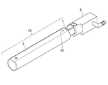
図2および3は、本発明の第1実施形態に係る洗浄ノズル10を示す図である。
本発明の洗浄ノズル10は、ノズル本体1と、筒状のノズルカバー2と、から構成され、ノズル取付部9を介して本体部に取り付けられる。ノズル本体1は、洗浄水を吐出する吐水孔11と、吐水孔11に洗浄水を供給する通水路12と、を有し、かつ、ノズルカバー2内に一部または全部が収納される。ノズルカバー2は、吐水孔11に対応した位置に連通孔21を有し、ノズルカバー2はさらに、非金属無機材質から構成される。
本発明の洗浄ノズル10は、ノズル本体1と、筒状のノズルカバー2と、から構成され、ノズル取付部9を介して本体部に取り付けられる。ノズル本体1は、洗浄水を吐出する吐水孔11と、吐水孔11に洗浄水を供給する通水路12と、を有し、かつ、ノズルカバー2内に一部または全部が収納される。ノズルカバー2は、吐水孔11に対応した位置に連通孔21を有し、ノズルカバー2はさらに、非金属無機材質から構成される。
ノズル本体1は、樹脂で構成されることが好ましい。樹脂成形によれば高い寸法精度が得られるため、洗浄水を吐出する際に高い照準精度が得られる。使用する樹脂としては特に限定されるものではなく、一般にシャワートイレ用ノズルに使用される樹脂材料を用いることができる。本発明においてノズル本体1はノズルカバー2に覆われて保護されるため、外面に防汚処理等をする必要がなく、洗浄水を供給する通水路12と、吐水孔11を備えていればよい。なお、ノズルカバー2の連通孔21を介して洗浄ノズル10に吐水孔別体を取り付けてもよい。その際に、吐水孔別体にも傷つきにくい部材を使用することがより好ましい。
ノズルカバー2は、ノズル駆動による摺動摩擦やブラシでの清掃に対して耐傷性の高い非金属無機材質で構成される。本実施形態においては外周面が釉薬処理された陶器材質で構成されるが、これに限定されず、ガラスやファインセラミックス等で構成されてもよい。具体的には、アルミナ、ジルコニア、炭化ケイ素および窒化ケイ素等を用いることができる。筒状のノズルカバー2は、内部にノズル本体1の一部または全部を収納して傷や汚れから保護する。
釉薬処理により形成される釉薬層3は、ノズルカバー2の清潔性や外観の意匠性を高める観点から、ノズルカバー2の外周面に形成される。釉薬層は透明であってもよいし、下地となる陶器材料やトイレの意匠等に合わせて、着色顔料を含んで構成されてもよい。
ノズル本体1とノズルカバー2との固定手段は特に限定されるものではなく、例えば好ましい手段として接着剤による接着が挙げられる。この方法によれば、接着剤の流動性が陶器の大きな寸法バラつきを吸収し、精密な固定を行うことが可能になる。
洗浄ノズル10はシャワートイレの駆動に伴い、長尺状の洗浄ノズル10の先端側から顕現してくるが、接着剤により形成された接着部4は、基端側のみに配置される。接着部4の位置や数としては特に限定されるものではないが、接着部4は視認されない位置に留めることが好ましく、ノズルカバーの外観品位を保つことが可能になる。接着剤は、一般に工業用に使用されるものを用いることができる。
またノズルカバー2において、接着部4におけるノズルカバー2の表面は、釉薬処理されていないことが好ましい。釉薬処理がされておらず、陶器下地表面の凹凸が存在することで、接着剤の接触面積が増加し、高い接着強度でノズル本体1とノズルカバー2とを固定することができる。
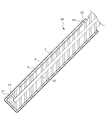
図7は、本発明のノズルカバー2および釉薬層3の層断面を示す図である。
釉薬処理により形成された釉薬層3は、前記陶器側から順に配置された、着色顔料を含有する有色釉薬層31と、顔料を含有しない無色透明の無色透明釉薬層32と、の二層で構成されてもよい。これにより、洗浄ノズル10に顔料の色味を付与しつつ光沢感が得られ、洗浄ノズル10、ひいては局部洗浄装置100の意匠性が向上する。
釉薬処理により形成された釉薬層3は、前記陶器側から順に配置された、着色顔料を含有する有色釉薬層31と、顔料を含有しない無色透明の無色透明釉薬層32と、の二層で構成されてもよい。これにより、洗浄ノズル10に顔料の色味を付与しつつ光沢感が得られ、洗浄ノズル10、ひいては局部洗浄装置100の意匠性が向上する。
以上、本実施形態に係る局部洗浄ノズル10によれば、以下のような効果を奏する。
(1) 本発明の実施形態に係る局部洗浄ノズル10は、ノズル本体1と、ノズル本体1を収納する筒状のノズルカバー2と、を備える局部洗浄ノズル10であって、ノズルカバー2は、非金属無機材質から構成される。
これにより、ノズル本体1は傷の付きにくいノズルカバー2によって保護され、洗浄ノズル10の清潔性が向上する。
これにより、ノズル本体1は傷の付きにくいノズルカバー2によって保護され、洗浄ノズル10の清潔性が向上する。
(2) 局部洗浄ノズル10において、ノズルカバー2は少なくとも外周面が釉薬処理された陶器からなる。
この方法によれば、ノズルカバー2は釉薬層によって保護されて防汚性を備えるため、洗浄ノズル10の清潔性が向上する。なお、釉薬層としては特に限定されるものではなく、例えば親水性や撥水性をノズルカバー2に付与するものとすることができる。
この方法によれば、ノズルカバー2は釉薬層によって保護されて防汚性を備えるため、洗浄ノズル10の清潔性が向上する。なお、釉薬層としては特に限定されるものではなく、例えば親水性や撥水性をノズルカバー2に付与するものとすることができる。
(3) 局部洗浄ノズル10において、前記ノズル本体1を前記ノズルカバー2に固定する固定手段をさらに備え、前記固定手段は、接着剤である。
この方法によれば、接着剤の流動性が陶器の大きな寸法バラつきを吸収し、精密な固定を行うことが可能になる。
この方法によれば、接着剤の流動性が陶器の大きな寸法バラつきを吸収し、精密な固定を行うことが可能になる。
(4) 局部洗浄ノズル10において、吐水孔11は、長尺状のノズル本体1の先端側に配置され、接着剤により形成された接着部4は、ノズル本体1の基端側のみに配置される。
接着部4を視認されにくい位置に留めることで、ノズルカバー2の外観品位を保つことが可能になる。
接着部4を視認されにくい位置に留めることで、ノズルカバー2の外観品位を保つことが可能になる。
(5) 局部洗浄ノズル10において、接着部4におけるノズルカバー2の表面は、釉薬処理されていない。
釉薬処理がされておらず、下地である陶器表面の凹凸が存在することで、接着剤の接触面積が増加し、高い接着強度でノズル本体1とノズルカバー2とを固定することができる。
釉薬処理がされておらず、下地である陶器表面の凹凸が存在することで、接着剤の接触面積が増加し、高い接着強度でノズル本体1とノズルカバー2とを固定することができる。
(6) 局部洗浄ノズル10において、釉薬処理により形成された釉薬層3は、陶器側から順に配置された、着色顔料を含有する有色釉薬層31と、顔料を含有しない無色透明の無色透明釉薬層32と、の二層で構成される。
これにより、洗浄ノズル10に顔料の色味を付与しつつ光沢感が得られ、洗浄ノズル10の意匠性が向上する。
これにより、洗浄ノズル10に顔料の色味を付与しつつ光沢感が得られ、洗浄ノズル10の意匠性が向上する。
(第2実施形態)
本発明の第2実施形態に係る局部洗浄装置200は、上記第1実施形態に係る局部洗浄装置100とは洗浄ノズル20の固定手段が異なる。図5に示す洗浄ノズル20では、ノズル本体1とノズルカバー2は樹脂ポッティング剤5を両者の隙間に充填して固定される。これにより、ノズルカバー2内でノズル本体1がぐらつくことなく、より安定して固定することができる。
本発明の第2実施形態に係る局部洗浄装置200は、上記第1実施形態に係る局部洗浄装置100とは洗浄ノズル20の固定手段が異なる。図5に示す洗浄ノズル20では、ノズル本体1とノズルカバー2は樹脂ポッティング剤5を両者の隙間に充填して固定される。これにより、ノズルカバー2内でノズル本体1がぐらつくことなく、より安定して固定することができる。
図4および5は、本発明の第2実施形態に係る洗浄ノズル20を示す図である。
図5に示すように、接着剤は樹脂ポッティング剤5であり、ノズル本体1とノズルカバー2との隙間に充填されてもよい。樹脂ポッティング剤5としては、ウレタン樹脂、エポキシ樹脂、アクリル樹脂、シリコーン樹脂等を用いることができる。樹脂ポッティング剤5は、ノズル本体1とノズルカバー2との隙間に充填されることで、ノズルカバー2内でノズル本体1がぐらつくことなく、より安定して固定することができる。
図5に示すように、接着剤は樹脂ポッティング剤5であり、ノズル本体1とノズルカバー2との隙間に充填されてもよい。樹脂ポッティング剤5としては、ウレタン樹脂、エポキシ樹脂、アクリル樹脂、シリコーン樹脂等を用いることができる。樹脂ポッティング剤5は、ノズル本体1とノズルカバー2との隙間に充填されることで、ノズルカバー2内でノズル本体1がぐらつくことなく、より安定して固定することができる。
また樹脂ポッティング剤5は、ウレタン樹脂またはシリコーン樹脂であることがより好ましい。ノズル本体1や樹脂ポッティング剤5は、通水路12を流れる洗浄水の温度によって膨張収縮するところ、ウレタン樹脂やシリコーン樹脂は弾性に富み、膨張収縮による樹脂ポッティング剤5およびノズルカバー2の割れが生じにくくなる。
さらに洗浄ノズル20は、ノズルカバー2の内側における連通孔21の周囲に配置されたシール部材6をさらに備えることが好ましい。これにより、製造時に樹脂ポッティング剤5が吐水孔11や連通孔21へ流れ込むのをシール部材6がせき止め、樹脂ポッティング剤5が洗浄水の流れに影響することを防ぐ効果がある。
図6は、本発明の第2実施形態に係る洗浄ノズル20の軸断面を示す図である。
図6に示すように、ノズルカバー2は、その内周面の少なくとも一部に形成された内周平面部22を有し、前記ノズル本体は、その外周面の少なくとも一部に形成されて前記内周平面部に当接する外周平面部13を有することが好ましい。これにより、ノズルカバー2の内部にノズル本体1を収納する際に平面部同士を合わせることで、ぐらつきを抑え、吐水孔11と連通孔21との位置合わせが容易かつ高精度に行われる。前述の第一実施形態においても有効であるが、特に本実施形態においてはポッティング剤5の注入時にノズルカバー2の内部でノズル本体1が動きやすいため、位置合わせの難易度が大きく改善する。
図6に示すように、ノズルカバー2は、その内周面の少なくとも一部に形成された内周平面部22を有し、前記ノズル本体は、その外周面の少なくとも一部に形成されて前記内周平面部に当接する外周平面部13を有することが好ましい。これにより、ノズルカバー2の内部にノズル本体1を収納する際に平面部同士を合わせることで、ぐらつきを抑え、吐水孔11と連通孔21との位置合わせが容易かつ高精度に行われる。前述の第一実施形態においても有効であるが、特に本実施形態においてはポッティング剤5の注入時にノズルカバー2の内部でノズル本体1が動きやすいため、位置合わせの難易度が大きく改善する。
以上、本実施形態に係る局部洗浄ノズル20によれば、(1)、(2)、(3)、(6)の効果に加え、以下のような効果を奏する。
(7) 局部洗浄ノズル20において、前記接着剤は、樹脂ポッティング剤である。
樹脂ポッティング剤がノズル本体とノズルカバーとの隙間に充填されることで、ノズルカバー内でノズル本体がぐらつくことなく、安定して固定することができる。
樹脂ポッティング剤がノズル本体とノズルカバーとの隙間に充填されることで、ノズルカバー内でノズル本体がぐらつくことなく、安定して固定することができる。
(8) 局部洗浄ノズル20において、前記樹脂ポッティング剤は、ウレタン樹脂またはシリコーン樹脂である。
ノズル本体や樹脂ポッティング剤は、通水路を流れる洗浄水の温度によって膨張収縮するところ、ウレタン樹脂やシリコーン樹脂は弾性に富み、膨張収縮による樹脂ポッティング剤およびノズルカバーの割れが生じにくくなる。
ノズル本体や樹脂ポッティング剤は、通水路を流れる洗浄水の温度によって膨張収縮するところ、ウレタン樹脂やシリコーン樹脂は弾性に富み、膨張収縮による樹脂ポッティング剤およびノズルカバーの割れが生じにくくなる。
(9) 局部洗浄ノズル20は、前記ノズルカバーの内側における前記連通孔の周囲に配置されたシール部材をさらに備える。
これにより、製造時に樹脂ポッティング剤が吐水孔や連通孔へ流れ込むのをシール部材がせき止め、樹脂ポッティング剤が洗浄水の流れに影響することを防ぐことができる。
これにより、製造時に樹脂ポッティング剤が吐水孔や連通孔へ流れ込むのをシール部材がせき止め、樹脂ポッティング剤が洗浄水の流れに影響することを防ぐことができる。
(10) 局部洗浄ノズル10において、ノズルカバー2は、その内周面の少なくとも一部に形成された内周平面部22を有し、ノズル本体1は、その外周面の少なくとも一部に形成されて内周平面部22に当接する外周平面部13を有する。
ノズルカバー2の内部にノズル本体1を収納する際に平面部同士を合わせることで、ぐらつきを抑え、吐水孔11と連通孔21との位置合わせが容易かつ高精度に行われる。
ノズルカバー2の内部にノズル本体1を収納する際に平面部同士を合わせることで、ぐらつきを抑え、吐水孔11と連通孔21との位置合わせが容易かつ高精度に行われる。
(11) また本発明は、(1)~(10)のいずれかの局部洗浄ノズルを備える、局部洗浄装置を提供する。
これにより、局部洗浄装置において(1)~(10)に記載の効果が得られる。
これにより、局部洗浄装置において(1)~(10)に記載の効果が得られる。
(第3実施形態)
本発明の第3実施形態に係る局部洗浄装置300は、上記第1実施形態に係る局部洗浄装置100とはノズルカバー32の材質が異なり、また洗浄ノズル30の固定手段が異なる。
本発明の第3実施形態に係る局部洗浄装置300は、上記第1実施形態に係る局部洗浄装置100とはノズルカバー32の材質が異なり、また洗浄ノズル30の固定手段が異なる。
図8および9は、本実施形態の洗浄ノズル30を示す図である。
本発明の洗浄ノズル30は、ノズル本体1と、筒状のノズルカバー302と、から構成され、ノズル取付部9を介して本体部に取り付けられる。ノズル本体1は、洗浄水を吐出する吐水孔11と、吐水孔11に洗浄水を供給する通水路12と、を有し、かつ、ノズルカバー2内に一部または全部が収納される。ノズルカバー302は、吐水孔11に対応した位置に連通孔21を有し、ノズルカバー302はさらに、少なくとも外周面が釉薬処理された金属下地からなる。
本発明の洗浄ノズル30は、ノズル本体1と、筒状のノズルカバー302と、から構成され、ノズル取付部9を介して本体部に取り付けられる。ノズル本体1は、洗浄水を吐出する吐水孔11と、吐水孔11に洗浄水を供給する通水路12と、を有し、かつ、ノズルカバー2内に一部または全部が収納される。ノズルカバー302は、吐水孔11に対応した位置に連通孔21を有し、ノズルカバー302はさらに、少なくとも外周面が釉薬処理された金属下地からなる。
ノズル本体1には、一般にシャワートイレ用ノズルに使用される樹脂等の材料を用いることができる。本発明においてノズル本体1はノズルカバー302に覆われて保護されるため、外面に防汚処理等をする必要がなく、洗浄水を供給する通水路12と、吐水孔11を備えていればよい。なお、ノズルカバー302の連通孔21を介して洗浄ノズル30に吐水孔別体を取り付けてもよい。その際に、吐水孔別体にも傷つきにくい部材を使用することがより好ましい。
ノズルカバー302は、ノズル駆動による摺動摩擦やブラシでの清掃に対して耐傷性の高い金属材料で構成される。筒状のノズルカバー302は、内部にノズル本体1の一部または全部を収納して傷や汚れから保護する。金属材料としては例えば、琺瑯やステンレスが好ましく用いられる。特にステンレスは錆が発生しにくいため、水濡れする環境の中でさらに長期的に清潔性を保つことが可能になる。
釉薬処理により形成される釉薬層3は、ノズルカバー302の清潔性や外観の意匠性を高める観点から、ノズルカバー302の外周面に形成される。釉薬層は透明であってもよいし、下地となる金属材料やトイレの意匠等に合わせて、着色顔料を含んで構成されてもよい。
ノズル本体1とノズルカバー302は、筒状のノズルカバー302の内部にノズル本体1を収納した状態で、互いに組み付け可能な固定手段を有することが好ましい。これにより、吐水孔11および連通孔21の相対位置を合わせた状態で維持することができ、両孔の位置ずれによって洗浄水の勢いを妨げることがない。
固定手段は特に限定されるものではなく、接着剤による接着のほか、ノズル本体1とノズルカバー302のいずれかに突起部および嵌合部を設け、金属の弾性を利用して嵌合することにより固定してもよい。例えば本実施形態においては、ノズルカバー302はスナップフィットにより、ノズル本体1の凸部14がノズルカバー302の凹部323に嵌合して固定される。金属性のノズルカバー302は加工が容易であるため、様々な固定手段を適用できる。
洗浄ノズル30はシャワートイレの駆動に伴い、長尺状の洗浄ノズル30の先端側から顕現してくるが、接着剤により形成された接着部4は、基端側のみに配置される。接着部4の位置や数としては特に限定されるものではないが、接着部4は視認されない位置に留めることが好ましく、接着部4を視認されない位置に留めることで、ノズルカバー302の外観品位を保つことが可能になる。接着剤は、一般に工業用に使用されるものを用いることができる。
ノズルカバー302は、その内周面の少なくとも一部に形成された内周平面部22を有し、前記ノズル本体は、その外周面の少なくとも一部に形成されて前記内周平面部に当接する外周平面部13を有することが好ましい。これにより、ノズルカバー302の内部にノズル本体1を収納する際に平面部同士を合わせることで、ぐらつきを抑え、吐水孔11と連通孔21との位置合わせが容易かつ高精度に行われる。
以上、本実施形態に係る局部洗浄ノズル30によれば、以下のような効果を奏する。
(12) 本発明の実施形態に係る局部洗浄ノズル30は、ノズル本体1と、ノズル本体1を収納する筒状のノズルカバー302と、を備える局部洗浄ノズル30であって、ノズルカバー302は、少なくとも外周面が釉薬処理された金属からなる。
これにより、ノズル本体は傷の付きにくいノズルカバー2によって保護され、洗浄ノズル10の清潔性が向上する。
これにより、ノズル本体は傷の付きにくいノズルカバー2によって保護され、洗浄ノズル10の清潔性が向上する。
(13) 局部洗浄ノズル30は、ノズル本体1をノズルカバー302に固定する固定手段をさらに備える。
これにより、吐水孔11および連通孔21の相対位置を合わせた状態で維持することができ、両孔の位置ずれによって洗浄水の勢いを妨げることがない。また、金属製のノズルカバー302は加工が容易であるほか弾性を有するために、固定手段の設計自由度が高い。
これにより、吐水孔11および連通孔21の相対位置を合わせた状態で維持することができ、両孔の位置ずれによって洗浄水の勢いを妨げることがない。また、金属製のノズルカバー302は加工が容易であるほか弾性を有するために、固定手段の設計自由度が高い。
(14) 局部洗浄ノズル30において、前記金属は、ステンレスである。
ステンレスは錆が発生しにくいため、水濡れする環境の中でさらに長期的に清潔性を保つことが可能になる。
ステンレスは錆が発生しにくいため、水濡れする環境の中でさらに長期的に清潔性を保つことが可能になる。
(15) 局部洗浄ノズル30において、釉薬処理により形成された釉薬層3は、金属側から順に配置された、着色顔料を含有する有色釉薬層31と、顔料を含有しない無色透明の無色透明釉薬層32と、の二層で構成される。
これにより、洗浄ノズル30に顔料の色味を付与しつつ光沢感が得られ、洗浄ノズル30の意匠性が向上する。
これにより、洗浄ノズル30に顔料の色味を付与しつつ光沢感が得られ、洗浄ノズル30の意匠性が向上する。
(16) また本発明は、(12)~(15)のいずれかの局部洗浄ノズルを備える、局部洗浄装置を提供する。
これにより、局部洗浄装置において(12)~(15)に記載の効果が得られる。
これにより、局部洗浄装置において(12)~(15)に記載の効果が得られる。
以上の実施形態に係る洗浄ノズルを有する局部洗浄装置によれば、洗浄ノズル表面に傷が付きにくい材質のノズルカバーを用いることで、傷部での汚れの堆積や菌の繁殖を防止し、ノズルの清潔性が向上する。
なお、本発明は上記実施形態に限定されるものではなく、本発明の目的を達成できる範囲での変形、改良は本発明に含まれる。
1 …ノズル本体
11…吐水孔
12…通水路
13…外周平面部
14…凸部
2,302…ノズルカバー
21…連通孔
22…内周平面部
23…凹部
3 …釉薬層
31…有色釉薬層
32…無色透明釉薬層
4 …接着部
5 …樹脂ポッティング剤
6 …シール部材
7 …便器
8 …便座
9 …ノズル取付部
10,20,30…洗浄ノズル
100,200,300…局部洗浄装置
110…ノズル駆動部
11…吐水孔
12…通水路
13…外周平面部
14…凸部
2,302…ノズルカバー
21…連通孔
22…内周平面部
23…凹部
3 …釉薬層
31…有色釉薬層
32…無色透明釉薬層
4 …接着部
5 …樹脂ポッティング剤
6 …シール部材
7 …便器
8 …便座
9 …ノズル取付部
10,20,30…洗浄ノズル
100,200,300…局部洗浄装置
110…ノズル駆動部
Claims (16)
- ノズル本体と、前記ノズル本体を収納する筒状のノズルカバーと、を備える局部洗浄ノズルであって、
前記ノズル本体は、洗浄水を吐出する吐水孔と、前記吐水孔に洗浄水を供給する通水路と、を有し、
前記ノズルカバーは、前記吐水孔に対応する位置に形成されて前記吐水孔に連通する連通孔を有するとともに、非金属無機材質から構成される、局部洗浄ノズル。 - 前記ノズルカバーは、少なくとも外周面が釉薬処理された陶器からなる、請求項1に記載の局部洗浄ノズル。
- 前記ノズル本体を前記ノズルカバーに固定する固定手段をさらに備え、
前記固定手段は、接着剤である、請求項1または2に記載の局部洗浄ノズル。 - 前記吐水孔は、長尺状の前記ノズル本体の先端側に配置され、
前記接着剤により形成された接着部は、前記ノズル本体の基端側に配置される、請求項3に記載の局部洗浄ノズル。 - 前記接着部における前記ノズルカバーの表面は、釉薬処理されていない、請求項3または4に記載の局部洗浄ノズル。
- 前記接着剤は、樹脂ポッティング剤である、請求項3に記載の局部洗浄ノズル。
- 前記樹脂ポッティング剤は、ウレタン樹脂またはシリコーン樹脂である、請求項6に記載の局部洗浄ノズル。
- 前記ノズルカバーの内側における前記連通孔の周囲に配置されたシール部材をさらに備える、請求項6または7のいずれかに記載の局部洗浄ノズル。
- 前記ノズルカバーは、その内周面の少なくとも一部に形成された内周平面部を有し、
前記ノズル本体は、その外周面の少なくとも一部に形成されて前記内周平面部に当接する外周平面部を有する、請求項1~8のいずれかに記載の局部洗浄ノズル。 - 前記釉薬処理により形成された釉薬層は、前記陶器側から順に配置された、着色顔料を含有する有色釉薬層と、顔料を含有しない無色透明の無色透明釉薬層と、の二層で構成される、請求項1~9のいずれかに記載の局部洗浄ノズル。
- 請求項1~10のいずれかに記載の局部洗浄ノズルを備える、局部洗浄装置。
- ノズル本体と、前記ノズル本体を収納する筒状のノズルカバーと、を備える局部洗浄ノズルであって、
前記ノズル本体は、洗浄水を吐出する吐水孔と、前記吐水孔に洗浄水を供給する通水路と、を有し、
前記ノズルカバーは、前記吐水孔に対応する位置に形成されて前記吐水孔に連通する連通孔を有するとともに、少なくとも外周面が釉薬処理された金属下地からなる、局部洗浄ノズル。 - 前記ノズル本体を前記ノズルカバーに固定する固定手段をさらに備える、請求項12に記載の局部洗浄ノズル。
- 前記金属は、ステンレスである、請求項12または13に記載の局部洗浄ノズル。
- 前記釉薬処理により形成される釉薬層は、前記金属下地側から順に、着色顔料を含有する有色釉薬層と、顔料を含有しない無色透明の無色透明釉薬層と、の二層で構成される、請求項12~14のいずれかに記載の局部洗浄ノズル。
- 請求項12~15のいずれかに記載の局部洗浄ノズルを備える、局部洗浄装置。
Applications Claiming Priority (6)
| Application Number | Priority Date | Filing Date | Title |
|---|---|---|---|
| JP2018163836 | 2018-08-31 | ||
| JP2018163837A JP2020033856A (ja) | 2018-08-31 | 2018-08-31 | 局部洗浄ノズルおよび局部洗浄装置 |
| JP2018-163836 | 2018-08-31 | ||
| JP2018-163837 | 2018-08-31 | ||
| JP2019-008585 | 2019-01-22 | ||
| JP2019008585A JP2020037848A (ja) | 2018-08-31 | 2019-01-22 | 局部洗浄ノズルおよび局部洗浄装置 |
Publications (1)
| Publication Number | Publication Date |
|---|---|
| WO2020044917A1 true WO2020044917A1 (ja) | 2020-03-05 |
Family
ID=69642692
Family Applications (1)
| Application Number | Title | Priority Date | Filing Date |
|---|---|---|---|
| PCT/JP2019/029846 Ceased WO2020044917A1 (ja) | 2018-08-31 | 2019-07-30 | 局部洗浄ノズルおよび局部洗浄装置 |
Country Status (1)
| Country | Link |
|---|---|
| WO (1) | WO2020044917A1 (ja) |
Citations (5)
| Publication number | Priority date | Publication date | Assignee | Title |
|---|---|---|---|---|
| JP2004299933A (ja) * | 2003-03-28 | 2004-10-28 | Toto Ltd | 衛生陶器の製造方法 |
| JP2004316150A (ja) * | 2003-04-14 | 2004-11-11 | Matsushita Electric Ind Co Ltd | トイレ装置 |
| JP2006348545A (ja) * | 2005-06-15 | 2006-12-28 | Matsushita Electric Ind Co Ltd | 局部洗浄ノズル |
| JP4343211B2 (ja) * | 2006-11-13 | 2009-10-14 | 株式会社東芝 | 便座装置 |
| JP2010101153A (ja) * | 2008-09-29 | 2010-05-06 | Panasonic Corp | ノズル装置とそれを用いた、衛生洗浄装置 |
-
2019
- 2019-07-30 WO PCT/JP2019/029846 patent/WO2020044917A1/ja not_active Ceased
Patent Citations (5)
| Publication number | Priority date | Publication date | Assignee | Title |
|---|---|---|---|---|
| JP2004299933A (ja) * | 2003-03-28 | 2004-10-28 | Toto Ltd | 衛生陶器の製造方法 |
| JP2004316150A (ja) * | 2003-04-14 | 2004-11-11 | Matsushita Electric Ind Co Ltd | トイレ装置 |
| JP2006348545A (ja) * | 2005-06-15 | 2006-12-28 | Matsushita Electric Ind Co Ltd | 局部洗浄ノズル |
| JP4343211B2 (ja) * | 2006-11-13 | 2009-10-14 | 株式会社東芝 | 便座装置 |
| JP2010101153A (ja) * | 2008-09-29 | 2010-05-06 | Panasonic Corp | ノズル装置とそれを用いた、衛生洗浄装置 |
Similar Documents
| Publication | Publication Date | Title |
|---|---|---|
| US7069615B2 (en) | Squeegee device and system | |
| HU215677B (hu) | Könnyen tisztítható zuhanyrózsa | |
| US5983433A (en) | Foot cleaning device | |
| WO2004024016A3 (en) | Toothbrush with transparent handle | |
| US10542849B2 (en) | Elastomeric holder | |
| ATE514355T1 (de) | Zahnbürste mit verbesserter/em reinigung und komfort | |
| DE60015491D1 (de) | Oberflächenreinigungsgerät mit rotier- und schwenkbarem reinigungsteil | |
| WO2020044917A1 (ja) | 局部洗浄ノズルおよび局部洗浄装置 | |
| JP2020037848A (ja) | 局部洗浄ノズルおよび局部洗浄装置 | |
| JP2020033856A (ja) | 局部洗浄ノズルおよび局部洗浄装置 | |
| US20070011806A1 (en) | Self-cleaning sink/wash basin | |
| JP2020076311A (ja) | 浴室用床パン | |
| ATE336195T1 (de) | Automatisch gesäuberter toilettensitz mit eingebauten mitteln zum auffangen der säuberungsflüssigkeit | |
| ITBS20000128A0 (it) | Apparecchio per la pulizia di scope, spazzole e simili | |
| JP2005537857A5 (ja) | ||
| JP2020165101A (ja) | 局部洗浄ノズル | |
| JP5041512B2 (ja) | 飲食物用断熱容器 | |
| DE69511237D1 (de) | Reinigungsgerät | |
| US1117771A (en) | Towel-rack. | |
| US20050125893A1 (en) | Multi-purpose kitchen pull-out faucet | |
| JP2017055962A (ja) | 洗濯機 | |
| SE0400469D0 (sv) | Dishwasher | |
| MX2008010907A (es) | Dispositivo de limpieza. | |
| JP2538789Y2 (ja) | 衛生洗浄装置 | |
| JP2020165099A (ja) | 局部洗浄ノズルおよびその製造方法 |
Legal Events
| Date | Code | Title | Description |
|---|---|---|---|
| 121 | Ep: the epo has been informed by wipo that ep was designated in this application |
Ref document number: 19854416 Country of ref document: EP Kind code of ref document: A1 |
|
| NENP | Non-entry into the national phase |
Ref country code: DE |
|
| 122 | Ep: pct application non-entry in european phase |
Ref document number: 19854416 Country of ref document: EP Kind code of ref document: A1 |