WO2020044581A1 - X線位相イメージング装置 - Google Patents
X線位相イメージング装置 Download PDFInfo
- Publication number
- WO2020044581A1 WO2020044581A1 PCT/JP2018/044352 JP2018044352W WO2020044581A1 WO 2020044581 A1 WO2020044581 A1 WO 2020044581A1 JP 2018044352 W JP2018044352 W JP 2018044352W WO 2020044581 A1 WO2020044581 A1 WO 2020044581A1
- Authority
- WO
- WIPO (PCT)
- Prior art keywords
- ray
- grating
- image
- control unit
- imaging apparatus
- Prior art date
- Legal status (The legal status is an assumption and is not a legal conclusion. Google has not performed a legal analysis and makes no representation as to the accuracy of the status listed.)
- Ceased
Links
Images






Classifications
-
- A—HUMAN NECESSITIES
- A61—MEDICAL OR VETERINARY SCIENCE; HYGIENE
- A61B—DIAGNOSIS; SURGERY; IDENTIFICATION
- A61B6/00—Apparatus or devices for radiation diagnosis; Apparatus or devices for radiation diagnosis combined with radiation therapy equipment
Definitions
- the present invention relates to an X-ray phase imaging apparatus, and more particularly, to an X-ray phase imaging apparatus that generates a phase contrast image including at least one of an absorption image, a phase differential image, and a dark field image.
- an X-ray phase imaging apparatus that generates a phase contrast image including at least one of an absorption image, a phase differential image, and a dark field image is known.
- Such an X-ray phase imaging apparatus is disclosed, for example, in International Publication WO2014 / 030115.
- WO 2014/030115 discloses an X-ray source, an X-ray detector, and a plurality of gratings (a source grating, a phase grating (first grating) and a plurality of gratings arranged between the X-ray source and the X-ray detector).
- An analyzer grating (second grating)) is disclosed.
- the source grating, the phase grating, and the analyzer grating are arranged in this order from the X-ray source side to the X-ray detector side. .
- X-rays emitted from an X-ray source and passed through a source grating pass through the phase grating, so that the phase grating is positioned at a predetermined distance from the phase grating.
- a self-image is formed.
- the X-ray detector is configured to detect interference fringes (moire fringes) generated by interference between the self-image and the analyzer grating.
- one of a plurality of gratings is translated (stripe scanning) at a predetermined cycle, and a plurality of changes in moire fringes are detected by an X-ray detector.
- a plurality of X-ray images are generated by detecting (photographing) times.
- a plurality of acquired images based on each of a plurality of X-ray detection signals detected by an X-ray detector, and an extracted image in which parameters of the plurality of acquired images are extracted And a phase contrast image including at least one of an absorption image, a phase differential image, and a dark field image based on the extracted image is generated.
- the absorption image is an X-ray image obtained by imaging a difference in the degree of X-ray absorption between subjects.
- the phase differential image is an X-ray image obtained by imaging the phase shift of the X-ray.
- the dark-field image is a visibility image obtained by a change in visibility (clarity) based on small-angle scattering of an object.
- a change in moire fringes is photographed a plurality of times by an X-ray detector.
- the X-ray dose (luminance) output from the X-ray source may change.
- the magnitude (intensity) of the X-ray detection signal varies between the acquired images, so that the phase contrast generated based on the plurality of acquired images is generated.
- Artifacts may be formed in images.
- a dedicated luminance detection area for measuring the luminance of an X-ray source is provided when imaging by fringe scanning is performed. It is conceivable that the magnitude of the detection signal is corrected based on the obtained luminance so as to reduce the variation in the intensity generated between a plurality of images obtained by the fringe scanning.
- the dedicated luminance detection area it is possible to suppress the occurrence of an artifact in the phase contrast image due to a change in the luminance of the X-ray source when performing imaging by fringe scanning. Since the brightness detection area needs to be provided separately from the shooting area for shooting the subject, there is a problem that the effective shooting area is reduced. Further, since it is necessary to configure the brightness detection area so that the grid, other components, the subject, and the like do not appear in the brightness detection area, there is a problem that the device configuration is complicated.
- a luminance detection sensor for measuring the luminance of an X-ray source is used as an X-ray detector when imaging by fringe scanning. May be provided separately.
- the above-described luminance detection sensor it is possible to suppress the occurrence of an artifact in the phase contrast image due to a change in the luminance of the X-ray source when performing imaging by fringe scanning.
- the configuration of the device is complicated by the provision of the luminance detection sensor.
- an object of the present invention is to provide an X-ray phase imaging apparatus capable of suppressing the occurrence of artifacts in a phase contrast image due to a change in the brightness of an X-ray source when performing imaging by fringe scanning. .
- an X-ray phase imaging apparatus includes an X-ray source, a detector that detects X-rays emitted from the X-ray source, an X-ray source and a detector.
- a first grating arranged between the first grating and the X-ray source, and a second grating arranged between the first grating and the detector and irradiated with the X-ray from the first grating;
- a fringe scan for translating at least one of the grating, the X-ray source, the detector, and an object disposed between the X-ray source and the detector at a predetermined cycle.
- An X-ray source by changing the magnitude of at least one of the plurality of detection signals so that the degree of artifact in the extracted image or the phase contrast image is equal to or less than a predetermined threshold.
- a controller that corrects a variation in the X-ray dose detected by the detector due to a change in the X-ray dose output from the controller.
- the control unit determines the magnitude of at least one of the plurality of detection signals so that the degree of artifact in the extracted image or the phase contrast image is predetermined.
- the configuration is such that the variation of the X-ray dose detected by the detector due to the change of the X-ray dose output from the X-ray source is corrected.
- variation in the magnitude between the plurality of detection signals can be reduced, so that an artifact occurs in the phase contrast image due to a change in the luminance of the X-ray source when performing imaging by fringe scanning. Can be suppressed.
- At least one of the plurality of detection signals is provided.
- the size so that the degree of artifact in the extracted image or the phase contrast image is equal to or less than a predetermined threshold value, it is possible to correct the variation in the X-ray dose.
- the phase due to the change in the brightness of the X-ray source when performing imaging by fringe scanning is reduced. It is possible to suppress the occurrence of artifacts in the contrast image.
- the control unit preferably multiplies or divides at least one of the plurality of detection signals by a correction coefficient for correcting a variation in the X-ray dose. By doing so, it is configured to correct the variation of the X-ray dose.
- the magnitude of at least one of the plurality of detection signals can be easily changed by multiplying or dividing the magnitude of at least one of the plurality of detection signals by the correction coefficient.
- the variation of the X-ray dose can be easily corrected.
- the control unit is configured to correct the variation in the X-ray dose by repeatedly multiplying or dividing the at least one of the plurality of detection signals by changing the correction coefficient.
- at least one of the plurality of detection signals is repeatedly multiplied or divided by changing the correction coefficient, thereby multiplying one type of correction coefficient without changing the correction coefficient.
- the magnitude of at least one of the plurality of detection signals can be changed widely as compared with the case of division. As a result, the magnitude of at least one of the plurality of detection signals can be reliably changed such that the degree of artifact in the extracted image or the phase contrast image is equal to or less than a predetermined threshold.
- the control unit is configured to set the correction coefficient based on a change rate of an output value of the X-ray dose output from the X-ray source. ing.
- the control unit is configured to set the correction coefficient based on a change rate of an output value of the X-ray dose output from the X-ray source. ing.
- the control unit changes all the magnitudes of the plurality of detection signals so that the degree of the artifact in the extracted image is equal to or less than a predetermined threshold
- the apparatus is configured to correct the variation in the X-ray amount detected by the detector due to the change in the X-ray amount output from the X-ray source.
- the control unit is configured to control a target of the translational movement in which at least one of the plurality of detection signals and at least one of the plurality of detection signals are detected.
- the control unit is configured to control a target of the translational movement in which at least one of the plurality of detection signals and at least one of the plurality of detection signals are detected.
- phase-contrast image can be suppressed due to the above-mentioned operation, and the occurrence of an artifact in the phase-contrast image due to the relative difficulty in precisely controlling the translation can be suppressed. be able to.
- the control unit includes a correction coefficient for correcting at least one of a variation in the X-ray dose or a displacement of a translation position of the translation target due to the translation.
- the correction coefficient is changed based on an estimation rule for changing the correction coefficient learned by reinforcement learning as machine learning so that the degree of the artifact is reduced based on the degree of the artifact.
- the correction coefficient can be changed as follows.
- the control unit is configured to determine a degree of an artifact based on a standard deviation of pixel values of a plurality of pixels of the extracted image or the phase contrast image.
- the standard deviation (pixel value variation) of the pixel values of the plurality of pixels becomes about the background noise (noise that is commonly present in all images) in the image, and thus the It can be considered that the variation in the magnitude of the detection signal between the images has been corrected, so that the degree of the artifact in a plurality of pixels can be easily determined.
- the plurality of gratings are arranged between the X-ray source and the first grating to enhance coherence of X-rays emitted from the X-ray source.
- a third grating preferably, the third grating can form the self-image of the first grating without depending on the focal diameter of the X-ray source, so that the degree of freedom in selecting the X-ray source can be improved. it can.
- the luminance of the X-ray source is reduced when performing imaging by fringe scanning while suppressing the effective imaging area from being reduced and suppressing the device configuration from becoming complicated. It is possible to suppress the occurrence of an artifact in the phase contrast image due to the change.
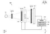
- FIG. 2 is a diagram for explaining a grating position adjustment mechanism of the X-ray phase imaging apparatus according to one embodiment.
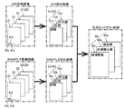
- FIG. 3 is a diagram for explaining generation of a phase contrast image in the X-ray phase imaging device according to one embodiment.
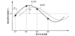
- FIG. 4 is a diagram for explaining parameters of a step curve.
- FIG. 4 is a diagram for explaining a variation in an X-ray dose detected by a detector due to a change in an X-ray dose output from an X-ray tube.
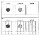
- FIGS. 7A and 7B are diagrams for explaining an artifact that occurs in a phase contrast image due to a variation in an X-ray dose; FIGS.
- FIG. 9 is a flowchart of correcting a variation in X-ray dose.
- FIG. 9 is a diagram for explaining a method of determining the degree of an artifact in an extracted image.
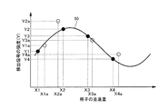
- FIG. 11 is a diagram for explaining a variation in an X-ray dose detected by a detector and a displacement of a translation position of a grating caused by translation in a first modification of the X-ray phase imaging apparatus.
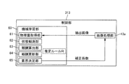
- FIG. 9 is a block diagram illustrating an overall configuration of a second modification of the X-ray phase imaging apparatus. It is a block diagram showing composition of a machine learning part of the 2nd modification of an X-ray phase imaging device.
- FIG. 13 is a block diagram showing the overall configuration of another modification of the X-ray phase imaging device.
- the X-ray phase imaging apparatus 100 is an apparatus that images the inside of the subject S using the Talbot effect.
- the X-ray phase imaging apparatus 100 includes an X-ray tube 11, a detector 12, a plurality of gratings G including a first grating G1, a second grating G2, and a third grating G3, a control unit 13, A lattice position adjustment mechanism 14 and a subject stage 15 are provided.
- the X-ray tube 11 is an example of the “X-ray source” in the claims.
- the X-ray tube 11, the third grating G3, the first grating G1, the second grating G2, and the detector 12 are arranged so that the X-ray irradiation axis direction (optical axis direction, Z Direction) in this order. That is, the first grating G1, the second grating G2, and the third grating G3 are arranged between the X-ray tube 11 and the detector 12.
- the direction from the X-ray tube 11 toward the first grating G1 is defined as a Z2 direction
- the opposite direction is defined as a Z1 direction.
- the direction of the grating pitch (described later) of each of the plurality of gratings G is defined as a Y direction
- the directions orthogonal to the Z direction and the Y direction are defined as an X direction.
- the X-ray tube 11 is an X-ray generator capable of generating X-rays when a high voltage is applied.
- the X-ray tube 11 is configured to irradiate the generated X-ray in the Z2 direction.
- the X-ray dose generated (output) from the X-ray tube 11 may vary within a range of approximately ⁇ 1% depending on the specifications of the X-ray tube 11.
- the detector 12 detects the X-rays emitted from the X-ray tube 11 and converts the detected X-rays into an electric signal.
- the detector 12 is, for example, an FPD (Flat @ Panel @ Detector).
- the detector 12 includes a plurality of conversion elements (not shown) and pixel electrodes (not shown) arranged on the plurality of conversion elements.
- the plurality of conversion elements and the pixel electrodes are arranged in the X direction and the Y direction at a predetermined cycle (pixel pitch).
- the detection signal (image signal) of the detector 12 is sent to an image processing unit 13a (described later) provided in the control unit 13.
- the first grating G1 has slits G1a and X-ray phase change portions G1b arranged at a predetermined period (grating pitch) d1 in the Y direction. Each slit G1a and the X-ray phase change portion G1b are formed so as to extend linearly in the X direction.
- the first grating G1 is a so-called phase grating.
- the first grating G1 is disposed between the X-ray tube 11 and the second grating G2, and is provided to form a self-image (by the Talbot effect) by the X-rays emitted from the X-ray tube 11. I have.
- the Talbot effect is such that when the coherent X-ray passes through the first grating G1 in which the slit G1a is formed, the first grating G1 is located at a predetermined distance (Talbot distance) from the first grating G1. (Self image) is formed.
- the second grating G2 has a plurality of X-ray transmitting portions G2a and X-ray absorbing portions G2b arranged at a predetermined period (grating pitch) d2 in the Y direction. Each X-ray transmitting portion G2a and X-ray absorbing portion G2b are formed so as to extend linearly in the X direction.
- the second grating G2 is a so-called absorption grating.
- the second grating G2 is arranged between the first grating G1 and the detector 12, and is configured to interfere with the self-image formed by the first grating G1.
- the second grating G2 is arranged at a position away from the first grating G1 by the Talbot distance in order to cause the self-image and the second grating G2 to interfere with each other. That is, in the X-ray phase imaging apparatus 100, the interference fringes (Moire fringes) generated by the interference between the self-image and the second grating G2 are detected by the detector 12 as X-rays.
- the third grating G3 has a plurality of slits G3a and X-ray absorbing portions G3b arranged at a predetermined period (pitch) d3. Each of the slits G3a and the X-ray absorbing portion G3b is formed to extend linearly in the X direction.
- the third grating G3 is arranged between the X-ray tube 11 and the first grating G1, and is irradiated with X-rays from the X-ray tube 11.
- the third grating G3 is configured to use the X-rays that have passed through each slit G3a as a line light source corresponding to the position of each slit G3a. That is, the third grating G3 is provided to increase the coherence of the X-rays emitted from the X-ray tube 11.
- the control unit 13 includes an image processing unit 13a that can generate an image.
- the control unit 13 is configured to control the operations of the lattice position adjustment mechanism 14 and the subject stage 15.
- Control unit 13 includes, for example, a CPU (Central Processing Unit), a ROM (Read Only Memory), a RAM (Random Access Memory), and the like.
- the image processing unit 13a is configured to generate an image such as the phase contrast image 40 (see FIG. 3) based on the detection signal sent from the detector 12.
- the image processing unit 13a includes, for example, a processor such as a GPU (Graphics Processing Unit) or an FPGA (Field-Programmable Gate Array) configured for image processing. The details of generation of the phase contrast image 40 (see FIG. 3) by the image processing unit 13a will be described later.
- the grating position adjusting mechanism 14 adjusts the first grating G1 to the X direction, the Y direction, the Z direction, the rotation direction Rz around the axis in the Z direction, the rotation direction Rx around the axis in the X direction, and , And is movable in a rotation direction Ry about an axis in the Y direction.
- the lattice position adjustment mechanism 14 includes an X-direction translation mechanism 14a, a Z-direction translation mechanism 14b, a Y-direction translation mechanism 14c, a translation mechanism connection section 14d, a stage support driving section 14e, and a stage support section. 14f, a stage driving unit 14g, and a stage 14h.
- the X-direction translation mechanism 14a, the Z-direction translation mechanism 14b, and the Y-direction translation mechanism 14c are configured to be movable in the X, Z, and Y directions, respectively.
- the X-direction translation mechanism 14a, the Z-direction translation mechanism 14b, and the Y-direction translation mechanism 14c include, for example, a stepping motor.
- the lattice position adjusting mechanism 14 moves the first lattice G1 in the X direction, the Z direction, and the Y direction, respectively, by the operations of the X direction linear moving mechanism 14a, the Z direction linear moving mechanism 14b, and the Y direction linear moving mechanism 14c. It is configured as follows.
- the stage support 14f supports the stage 14h for mounting (or holding) the first lattice G1 from the Z2 direction.
- the stage drive unit 14g is configured to reciprocate the stage 14h in the X direction.
- the stage 14h has a bottom formed in a convex curved shape toward the stage support portion 14f, and is configured to rotate around an axis in the Y direction (Ry direction) by being reciprocated in the X direction. I have.
- the stage support driving unit 14e is configured to reciprocate the stage support 14f in the Y direction.
- the linear motion mechanism connecting portion 14d is provided on the X direction linear motion mechanism 14a so as to be rotatable around the axis in the Z direction (Rz direction).
- the stage support portion 14f has a bottom portion formed in a convex curved shape toward the linear motion mechanism connection portion 14d, and reciprocates in the Y direction to rotate around the axis in the X direction (Rx direction). It is configured as follows.
- the grid position adjusting mechanism 14 may include a mechanism for holding the first grid G1, such as a chuck mechanism or a hand mechanism.
- the subject stage 15 has a mounting surface (not shown) on which the subject S is mounted.
- the subject stage 15 is configured to be movable in the X and Y directions under the control of the control unit 13 with the subject S placed on the placement surface.
- the subject stage 15 is composed of, for example, an XY stage.
- the subject stage 15 may have a mechanism for holding the subject S, such as a chuck mechanism or a hand mechanism, for example.
- the phase contrast image 40 refers to at least one of the plurality of gratings G, the X-ray tube 11, the subject S, and the detector 12 at a predetermined cycle. This is an image generated based on the acquired image 20 (see FIG. 3) detected by the detector 12 by performing stripe scanning for translation (step).
- the first grating G1 is operated by the operation of the Y-direction linear movement mechanism 14c (see FIG. 2) of the grating position adjustment mechanism 14. Is configured to perform fringe scanning with the object of translation.
- the image processing unit 13a generates a plurality of acquired images 20 based on each of the plurality of X-ray detection signals detected by the detector 12 by performing the fringe scanning. It is configured to be.
- an AIR acquired image 21 and a SAMPLE acquired image 22 are generated as the acquired images 20.
- the AIR acquisition image 21 is an image obtained by imaging a detection signal detected by the detector 12 in a state where the subject S is not arranged between the X-ray tube 11 and the detector 12.
- the SAMPLE acquired image 22 is an image obtained by imaging a detection signal detected by the detector 12 in a state where the subject S is arranged between the X-ray tube 11 and the detector 12.
- the image processing unit 13a is configured to generate an extracted image 30 obtained by extracting parameters from the plurality of acquired images 20.
- an AIR extracted image 31 and a SAMPLE extracted image 32 are generated as the extracted images 30.
- the AIR extraction image 31 and the SAMPLE extraction image 32 are images obtained by extracting parameters from the plurality of AIR acquisition images 21 and parameters from the plurality of SAMPLE acquisition images 22, respectively.
- the image processing unit 13a is configured to generate a phase contrast image 40 based on the AIR extracted image 31 and the SAMPLE extracted image 32.
- the phase contrast image 40 includes an absorption image 40a, a phase differential image 40b, and a dark field image 40c.
- the absorption image 40a is an X-ray image obtained by imaging the difference in the degree of X-ray absorption by the subject S.
- the phase differential image 40b is an X-ray image obtained by imaging a shift of the X-ray phase P (see FIG. 4).
- the dark field image 40c is a visibility image obtained by a change in visibility (clearness) based on small-angle scattering of an object.
- the dark-field image 40c is also called a small-angle scattering image.
- the first grid G1 is moved by the grid position adjusting mechanism 14 in the direction of the grid pitch (Y X-rays are detected at a plurality of points X (see FIG. 4) of the translation amount of the grid G (first grid G1) while performing stripe scanning in a predetermined cycle in the (direction).
- the image processing unit 13 a determines the magnitude (intensity) Y (intensity) of the detection signal based on the magnitude (intensity) Y (see FIG. 4) of the detection signal detected by the detector 12. (See FIG. 4). Also, as shown in FIG. 1, in a state where the subject S is not arranged between the X-ray tube 11 and the detector 12, the first grid G1 is moved by the grid position adjusting mechanism 14 in the direction of the grid pitch (Y X-rays are detected at a plurality of points X (see FIG. 4) of the translation amount of the grid G (first grid G1) while performing stripe scanning in a predetermined cycle in the (direction).
- the first grid G1 is moved in the grid pitch direction (Y direction) by the grid position adjusting mechanism 14.
- X-rays are detected at a plurality of translational points X (see FIG. 4) of the grid G (first grid G1) while performing a fringe scan at a predetermined cycle.
- the image processing unit 13 a determines the magnitude (intensity) Y (intensity) of the detection signal based on the magnitude (intensity) Y (see FIG. 4) of the detection signal detected by the detector 12. (See FIG. 4).
- FIG. 3 shows an example in which four AIR acquired images 21 and four SAMPLE acquired images 22 are generated.
- the image processing unit 13a calculates the magnitude (intensity) Y of the detection signal for each of the pixels PX (see FIG. 3) with a sine function for the plurality of AIR-acquired images 21.
- a fitted signal intensity change curve (step curve) 51 is obtained.
- the image processing unit 13a extracts three types of parameters (average value C, phase P, and amplitude A) acquired from the step curve 51.
- the average value C, the phase P, and the amplitude A are generated as AIR extracted images 31a, 31b, and 31c, respectively.
- FIG. 3 the average value C, the phase P, and the amplitude A are generated as AIR extracted images 31a, 31b, and 31c, respectively.
- the image processing unit 13a fits the magnitude (intensity) Y of the detection signal to each of the pixels PX (see FIG. 3) using a sine function for the plurality of SAMPLE acquired images 22.
- the obtained signal intensity change curve (step curve) 52 is obtained.
- the image processing unit 13a extracts three types of parameters (average value C, phase P, and amplitude A) acquired from the step curve 52.
- the average value C, the phase P, and the amplitude A are generated as SAMPLE extracted images 32a, 32b, and 32c, respectively.
- illustration of the three types of parameters of the step curve 52 is omitted.
- the image processing unit 13a generates the absorption image 40a by calculating the average value C (SAMPLE) / the average value C (AIR) for each pixel PX. Further, the image processing unit 13a generates the phase differential image 40b by calculating the phase P (SAMPLE) ⁇ the phase P (AIR) for each pixel PX.
- the dark field image 40c is generated by calculating (amplitude A (SAMPLE) / average value C (SAMPLE)) / (amplitude A (AIR) / average value C (AIR)) for each pixel PX. .
- the average value C (AIR), phase P (AIR), and amplitude A (AIR) are parameters of the AIR extracted images 31a, 31b, and 31c, respectively.
- the average value C (SAMPLE), phase P (SAMPLE), and amplitude A (SAMPLE) are parameters of the SAMPLE extracted images 32a, 32b, and 32c, respectively.
- the amount of X-rays generated (output) from the X-ray tube 11 may change depending on the specifications of the X-ray tube 11. Therefore, as shown in FIG. 5, due to a change in the amount of X-ray output from the X-ray tube 11, a plurality of translational points X (X1, X2, X3 and X4), the X-ray dose detected by the detector 12 may vary (an error when the X-ray dose changes with respect to a case where the X-ray dose does not change). Note that FIG. 5 shows a state in which the magnitude (intensity) Y of the detection signal is shifted from the position on the step curve 50 when the X-ray dose does not vary due to the variation in the X-ray dose.
- the magnitude (intensity) Y of the detection signal at the points X1, X2, X3, and X4 of the translation amount of the grid G is Y1, Y2, Y3, and Y3 on the step curve 50, respectively. Y4.
- the magnitude (intensity) Y of the detection signal becomes Y1a, Y2a, Y3a, and Y4a shifted from the step curve 50.
- phase contrast image 40 is generated based on the step curves obtained from the magnitudes (intensities) Y1a, Y2a, Y3a, and Y4a of the detection signals deviated from the step curve 50 on which the X-ray dose does not vary, FIG. 6 (B), an unintended artifact AF occurs on the phase contrast image 40.
- the control unit 13 changes the magnitude Y of all of the plurality of detection signals so that the degree D of the artifact AF in the extracted image 30 is equal to or less than a predetermined Dth , thereby obtaining an X-ray. It is configured to correct the variation in the X-ray dose detected by the detector 12 due to the change in the X-ray dose output from the tube 11.
- the control unit 13 changes the correction coefficient KY (KY1, KY2, KY3, and KY4) for all the magnitudes Y of the plurality of detection signals and repeatedly divides the magnitudes, thereby reducing the variation in the X-ray dose. It is configured to correct. Further, the control unit 13 is configured to determine the degree D of the artifact AF based on the standard deviation of the pixel values of the plurality of pixels PX of the extracted image 30.
- the control unit 13 divides the magnitudes (intensities) Y1a, Y2a, Y3a, and Y4a of the detection signals by the correction coefficients KY1, KY2, KY3, and KY4, respectively. . That is, the control unit 13 sets the correction coefficient K as a coefficient for changing the magnitude (intensity) Y of the detection signal (Step 101 in FIG. 7).
- the correction coefficients KY1, KY2, KY3, and KY4 may have the same value or different values.
- the magnitudes (intensities) Y of the detection signals divided by the correction coefficients KY1, KY2, KY3, and KY4 are Y1a / KY1, Y2a / KY2, Y3a / KY3, and Y4a / KY4, respectively.
- the control unit 13 randomly changes the correction coefficients KY1, KY2, KY3, and KY4 (within a predetermined range) (Step 102 in FIG. 7).
- the control unit 13 is configured to set the correction coefficient KY based on the rate of change of the output value of the X-ray dose output from the X-ray tube 11 (a range of approximately ⁇ 1%). ing. That is, the control unit 13 sets the correction coefficients KY1, KY2, KY3, and KY4 within a range from about 0.99 to about 1.01.
- the control unit 13 obtains the change rate of the output value of the X-ray dose output from the X-ray tube 11 based on, for example, the specification of the X-ray tube 11 by an input by a user.
- control unit 13 acquires the step curve 50 from the values of Y1a / KY1, Y2a / KY2, Y3a / KY3, and Y4a / KY4. Then, the control unit 13 generates the extracted image 30 (see FIG. 3) based on the obtained step curve 50 (Step 103 in FIG. 7).
- the control unit 13 acquires a line profile (change in pixel value on the pixel column PL) in the arbitrary pixel column PL in the extracted image 30. Then, the control unit 13 calculates the degree of variation (standard deviation) of the pixel values included in the line profile as the degree D of the artifact AF (Step 104 in FIG. 7).
- the pixel row PL for acquiring the line profile may be any row in the image (extracted image 30), but is preferably a portion where the subject S is not reflected (a portion where there is no spatial information of the subject S).
- the control unit 13 compares the calculated standard deviation in the line profile with a predetermined threshold Dth set in advance (Step 105 in FIG. 7).
- the predetermined threshold D th is, for example, the standard deviation of the background noise in the image (the extracted image 30). Then, the control unit 13, the standard deviation in the calculated line profile, when it is determined that greater than a predetermined threshold D th, until less than a predetermined threshold value D th, the correction coefficient KY1, KY2, KY3 and KY4 Are repeated (steps 102 to 105 in FIG. 7).
- the control unit 13 determines that the calculated standard deviation in the line profile is smaller than the predetermined threshold value D th , the detection is detected by the detector 12 due to a change in the X-ray dose output from the X-ray tube 11.
- the correction of the variation of the X-ray dose ends.
- the values of Y1a / KY1, Y2a / KY2, Y3a / KY3 and Y4a / KY4 are the magnitudes (intensities) Y1, Y2, and Y3 of the detection signals on the step curve 50 when the X-ray dose is not varied.
- Y4 Therefore, the phase contrast image 40 from which the artifact AF shown in FIG. 6A has been removed is generated based on the step curve 50 when the X-ray dose shown in FIG. 5 does not vary.
- the control unit 13 changes all the magnitudes Y of the plurality of detection signals so that the degree D of the artifact AF in the extracted image 30 is equal to or less than a predetermined Dth.
- the configuration is such that variations in the X-ray dose detected by the detector 12 due to changes in the X-ray dose output from the X-ray tube 11 are corrected. Thereby, it is possible to reduce the variation in the magnitude Y between the plurality of detection signals. Further, by changing the magnitude Y of all of the plurality of detection signals so that the degree D of the artifact AF in the extracted image 30 is equal to or less than a predetermined threshold Dth , the luminance of the X-ray tube 11 is measured.
- Variations in the X-ray dose can be corrected without providing a dedicated luminance detection area or separately providing a luminance detection sensor for measuring the luminance of the X-ray tube 11.
- the luminance of the X-ray tube 11 changes when performing imaging by fringe scanning while suppressing the effective area of imaging from being reduced and suppressing the device configuration from becoming complicated.
- the occurrence of artifact AF in the phase contrast image 40 can be suppressed.
- the magnitude Y of all of the plurality of detection signals is changed, the occurrence of the artifact AF in the phase contrast image 40 is reduced as compared with the case where the magnitude Y of a part of the plurality of detection signals is changed. It can be more suppressed.
- the control unit 13 divides the correction coefficient KY for correcting the variation in the X-ray dose with respect to all the magnitudes Y of the plurality of detection signals, thereby obtaining X It is configured to correct the variation of the dose.
- the correction coefficient KY with respect to all the magnitudes Y of the plurality of detection signals, it is possible to easily change all the magnitudes Y of the plurality of detection signals to easily correct the variation of the X-ray dose. can do.
- the control unit 13 corrects the variation of the X-ray dose by repeatedly dividing the magnitude Y of all of the plurality of detection signals by changing the correction coefficient KY. It is constituted so that.
- the correction coefficient KY for all the magnitudes Y of the plurality of detection signals, a comparison is made with the case where one type of correction coefficient KY is divided without changing the correction coefficient KY.
- all the magnitudes Y of the plurality of detection signals can be changed widely.
- all the magnitudes Y of the plurality of detection signals can be reliably changed such that the degree D of the artifact AF in the extracted image 30 is equal to or less than the predetermined threshold Dth .
- the control unit 13 is configured to set the correction coefficient KY based on the change rate of the output value of the X-ray dose output from the X-ray tube 11.
- the correction coefficient is set according to the range in which the magnitude Y of the X-ray detection signal actually varies between the acquired images 20.
- KY can be changed.
- the range in which the correction coefficient KY is changed can be limited as compared with the case where the correction coefficient KY is changed without reference, all the magnitudes Y of the plurality of detection signals are determined by the artifact AF in the extracted image 30. Can be quickly changed so that the degree D becomes equal to or less than a predetermined threshold value Dth .
- control unit 13 is configured to determine the degree D of the artifact AF based on the standard deviation of the pixel values of the plurality of pixels PX of the extracted image 30.
- the standard deviation of pixel values (variation of pixel values) in the plurality of pixels PX becomes about the background noise (noise that is common to all images) in the image, and the Since the variation in the magnitude Y of the detection signal between the pixels PX can be regarded as being corrected, the degree D of the artifact AF in the plurality of pixels PX can be easily determined.
- the plurality of gratings G are arranged between the X-ray tube 11 and the first grating G1, and increase the coherence of X-rays emitted from the X-ray tube 11.
- the self-image of the first grating G1 can be formed by the third grating G3 without depending on the focal diameter of the X-ray tube 11, so that the degree of freedom in selecting the X-ray tube 11 can be improved. it can.
- the control unit 13 is configured to correct a variation in the X-ray dose detected by the detector 12 due to a change in the X-ray dose output from the X-ray tube 11.
- the present invention is not limited to this.
- the control unit 213 controls the translation position of the grid G (the grid G It may be configured to correct the displacement of the translation amount point X).
- the grating G (the first grating G1) is stripe-scanned by the grating position adjusting mechanism 14. Is configured.
- the period (lattice pitch) of the grating G is fine (on the order of ⁇ m)
- FIG. 9 the translational position of the grating G is not shifted due to the translational movement of the grating G (the translational position of the grating G is not shifted when the translational position of the grating G is shifted).
- the translational displacement of the grating G causes X indicates a state where the translation position of the lattice G is shifted from the position on the step curve 50 when the translation position is not shifted. That is, when the translation position of the lattice G is not displaced, the translation point of the lattice G is X1, X2, X3, and X4 while the translation position of the lattice G is displaced. In this case, the point X of the translation amount of the lattice G is X1a, X2a, X3a and X4a shifted from the step curve 50.
- the control unit 213 determines all the magnitudes Y of the plurality of detection signals and the translation positions of all the lattices G from which the plurality of detection signals have been obtained (the lattice G By changing the translation amount point X) such that the degree D of the artifact AF in the extracted image 30 is equal to or less than a predetermined Dth , the detector 12 caused by a change in the X-ray dose output from the X-ray tube 11 is changed. And the deviation of the translational position of the grating G due to the translation is corrected.
- control unit 213 changes the correction coefficient KY (KY1, KY2, KY3, and KY4) for all the magnitudes Y of the plurality of detection signals and repeatedly divides the magnitudes, thereby reducing the variation in the X-ray dose.
- the correction is performed while changing the correction coefficient KX (KX1, KX2, KX3, and KX4) for all the translation positions of the lattice G (the point X of the translation amount of the lattice G) from which the plurality of detection signals are acquired.
- the addition is configured to correct the displacement of the translation position of the grating G.
- the control unit 213 divides the magnitudes (intensities) Y1a, Y2a, Y3a, and Y4a of the detection signals by the correction coefficients KY1, KY2, KY3, and KY4, respectively. . Further, the control unit 213 adds the correction coefficients KX1, KX2, KX3, and KX4 to X1a, X2a, X3a, and X4a, respectively. That is, the control unit 313 sets the correction coefficients KY and KX as coefficients for changing the magnitude (intensity) Y of the detection signal and the point X of the translation amount of the grid G (Step 201 in FIG. 7).
- the correction coefficients KY1, KY2, KY3, KY4, KX1, KX2, KX3 and KX4 may have the same value or different values.
- the magnitudes (intensities) Y of the detection signals divided by the correction coefficients KY1, KY2, KY3, and KY4 are Y1a / KY1, Y2a / KY2, Y3a / KY3, and Y4a / KY4, respectively.
- the points X of the translation amount of the lattice G to which the correction coefficients KX5, KX6, KX7, and KX8 are added are X1a + KX1, X2a + KX2, X3a + KX3, and X4a + KX4, respectively.
- the control unit 213 changes the correction coefficients KY1, KY2, KY3, KY4, KX1, KX2, KX3, and KX4 (Step 202 in FIG. 7).
- the correction coefficients KY1, KY2, KY3, KY4, KX1, KX2, KX3 and KX4 change, Y1a / KY1, Y2a / KY2, Y3a / KY3, Y4a / KY4, X1a + KX1, X2a + KX2, X3a + KX3 and X3a + KX3 are X4a + KX3 and X4a.
- the control unit 213 sets the correction coefficients KX1, KX2, KX3, and KX4 based on, for example, the size of the period (grating pitch) of the grating G.
- control unit 213 acquires the step curve 50 from the values of Y1a / KY1, Y2a / KY2, Y3a / KY3, Y4a / KY4, X1a + KX1, X2a + KX2, X3a + KX3, and X4a + KX4. Then, the control unit 213 (the image processing unit 213a (see FIG. 1)) generates the extracted image 30 (see FIG. 3) based on the acquired step curve 50 (step 203 in FIG. 7).
- control unit 213 acquires a line profile (change in pixel value on the pixel column PL) in the arbitrary pixel column PL in the extracted image 30. Then, the control unit 213 calculates the degree of variation (standard deviation) of the pixel values included in the line profile as the degree D of the artifact AF (Step 204 in FIG. 7).
- control unit 213 compares the calculated standard deviation in the line profile with a predetermined threshold value Dth set in advance (Step 205 in FIG. 7). Then, the control unit 213, the standard deviation in the calculated line profile, when it is determined that greater than a predetermined threshold D th, until less than a predetermined threshold value D th, the correction coefficient KY1, KY2, KY3, ky4 , KX1, KX2, KX3 and KX4 are changed, and the flow (the flow of steps 202 to 205 in FIG. 7) is repeated.
- the control unit 213 determines that the calculated standard deviation in the line profile is smaller than a predetermined threshold D th , the detection is detected by the detector 12 due to a change in the X-ray dose output from the X-ray tube 11.
- the correction of the deviation of the translation position of the grating G due to the variation of the X-ray dose and the translation is ended.
- the values of Y1a / KY1, Y2a / KY2, Y3a / KY3 and Y4a / KY4 are the magnitudes (intensities) Y1, Y2, and Y3 of the detection signals on the step curve 50 when the X-ray dose is not varied. And Y4.
- the values of X1a + KX1, X2a + KX2, X3a + KX3, and X4a + KX4 are approximately equal to the points X1, X2, X3, and X4 of the translation amount of the grid G on the step curve 50 when the translation position of the grid G is not displaced. Become. Therefore, based on the step curve 50 when the X-ray dose shown in FIG. 9 is not varied and the translation position of the grating G is not displaced, the phase contrast from which the artifact AF shown in FIG. An image 40 is generated.
- the control unit 213 determines the magnitude Y of the plurality of detection signals and the translation position of all the lattices G where the plurality of detection signals are detected (the point of the translation amount of the lattice G).
- X is changed so that the degree D of the artifact AF becomes equal to or less than a predetermined threshold value D th , so that the translation position of the grid G (the point of the translation amount of the grid G) caused by the variation of the X dose and the translation. It is configured to correct both of the positional deviations of X).
- phase contrast image 40 due to the change in the phase contrast image 40 can be suppressed, and the phase contrast image 40 due to the relative difficulty in precisely controlling the translation of the grating G is relatively difficult. Can prevent the occurrence of the artifact AF.
- the control unit 13 is configured to change the correction coefficient K at random (within a predetermined range).
- the present invention is not limited to this. Absent.
- the control unit 313 performs an estimation rule for changing the correction coefficients KY and KX learned by reinforcement learning as machine learning.
- the correction coefficients KY and KX may be changed based on R.
- the X-ray phase imaging apparatus 300 includes a control unit 313.
- control unit 313 is configured to change the correction coefficients KY and KX based on an estimation rule R for changing the correction coefficient K learned by reinforcement learning as machine learning. (Step 302 in FIG. 7).
- the estimation rule R is learned by reinforcement learning as machine learning based on the correction coefficients KY and KX and the degree D of the artifact AF so that the degree D of the artifact AF is reduced.
- the control unit 313 includes a machine learning unit 60.
- the machine learning unit 60 has a function of performing so-called reinforcement learning.
- the X-ray phase imaging apparatus 300 is configured so that when the learning mode is selected by the user, the machine learning unit 60 performs reinforcement learning.
- the reinforcement learning is a type of machine learning, and refers to performing learning so as to maximize a reward obtained through trial and error in order to obtain more correct results for a problem to be solved.
- the machine learning unit 60 includes a physical quantity acquisition unit 61, a state observation unit 62, a reward calculation unit 63, a reward update unit 64, and a decision determination unit 65.
- the physical quantity acquisition unit 61 is configured to acquire the extracted image 30 from the image processing unit 13a when the extracted image 30 is generated by the image processing unit 13a. It is assumed that arbitrary correction coefficients KY and KX have been set at the first time when the physical quantity acquisition unit 61 acquires the extracted image 30. Further, it is assumed that the correction coefficient K changed by the decision making unit 65 is set in the second and subsequent times when the physical quantity acquisition unit 61 acquires the data of the extracted image 30.
- the state observation unit 62 is configured to calculate the degree D of the artifact AF in the extracted image 30 based on the extracted image 30 acquired by the physical quantity acquisition unit 61.
- the reward calculation unit 63 is configured to calculate the reward value such that the lower the degree D of the artifact AF, the higher the reward value. That is, in the X-ray phase imaging apparatus 300, the correlation between the degree D of the artifact AF and the reward value is set in advance.
- the reward updating unit 64 is configured to update the internal parameters of the machine learning unit 60 based on the reward value calculated by the reward calculating unit 63.
- the internal parameter is a parameter for determining the estimation rule R for changing the correction coefficients KY and KX so that the largest reward can be obtained.
- the decision making unit 65 changes the correction coefficients KY and KX based on the estimation rule R determined from the internal parameters updated by the reward updating unit 64, and performs image processing based on the changed correction coefficients KY and KX.
- the unit 13a is configured to generate the extracted image 30.
- the estimation rule R that changes the correction coefficient K sets the correction coefficients KY and KX so that the degree D of the artifact AF becomes small. Reinforcement learning is performed so that it can be changed well. That is, by using the estimation rule R subjected to the reinforcement learning, the number of times the correction coefficients KY and KX are changed until the degree D of the artifact AF in the extracted image 30 becomes equal to or less than the predetermined threshold Dth (steps S302 to S205 in FIG. 7). ) Can be reduced.
- the X-ray phase imaging apparatus 300 changes the correction coefficients KY and KX based on the estimation rule R subjected to the reinforcement learning, thereby comparing the X-ray dose with the case where the correction coefficient K is changed at random. It is possible to shorten the process (time) required for correcting the variation in the position and the displacement of the translation position of the grating G.
- the control unit 313 performs (correction of variation in X-ray dose based on the estimation rule R for changing the correction coefficients KY and KX learned by reinforcement learning as machine learning).
- the correction coefficient KY and the correction coefficient KX (for correcting the displacement of the translation position of the grating G due to the translation) are changed.
- the estimation rule R is learned based on the correction coefficients KY and KX and the degree D of the artifact AF by reinforcement learning as machine learning so that the degree D of the artifact AF is reduced.
- the degree D of the artifact AF is reduced based on the estimation rule R for changing the correction coefficients KY and KX learned by reinforcement learning, as compared with the case where the correction coefficients KY and KX are changed at random.
- the correction coefficients KY and KX can be changed efficiently.
- the control unit 13 (213, 313) is included in the line profile (change of the pixel value on the pixel column PL) as the degree D of the artifact AF.
- the degree D of the artifact AF is not limited to this.
- the control unit sets the degree D of the artifact AF as, for example, the variation (standard deviation) of the pixel values included in the (m ⁇ n) pixel regions, and the variation of the pixel values included in the line profile. You may comprise so that a value other than a condition (standard deviation) may be calculated.
- the control unit 13 controls the degree D of the artifact AF based on the standard deviation of the pixel values of the plurality of pixels PX of the extracted image 30.
- the control unit may be configured to determine the degree D of the artifact AF based on the standard deviation of the pixel values of the plurality of pixels PX of the phase contrast image 40.
- control unit is configured to determine the degree D of the artifact AF based on a numerical value other than the standard deviation of the pixel values of the plurality of pixels PX. Is also good.
- the control unit 13 (213, 313) controls the correction coefficient KY based on the rate of change of the output value of the X-ray dose output from the X-ray tube 11.
- the control unit may be configured to set the correction coefficient KY without being based on the rate of change.
- the control unit 13 (213, 313) is configured to repeatedly divide the magnitude Y of the detection signal by changing the correction coefficient KY.
- the present invention is not limited to this.
- the control unit may be configured to divide the correction coefficient KY only once for the magnitude Y of the detection signal.
- control unit 213 is configured to change the correction coefficient KX and add repeatedly to the translation position of the lattice G.
- the control unit may be configured to add the correction coefficient KX only once to the translation position of the lattice G.
- the control unit 13 (213, 313) is configured to divide the correction coefficient KY for the magnitude Y of the detection signal.
- the present invention is not limited to this.
- the control unit may be configured to multiply the magnitude Y of the detection signal by the correction coefficient KY, may be configured to add the correction coefficient KY, KY may be configured to be subtracted.
- control unit 213 is configured to add the correction coefficient KX to the translation position of the lattice G, but the present invention is not limited to this. Not limited to this. In the present invention, the control unit may be configured to subtract the correction coefficient KX from the translation position of the lattice G, may be configured to multiply the correction coefficient KX, or may be configured to multiply the correction coefficient KX. May be configured to divide.
- control unit 13 is configured to change the magnitude Y of the detection signal so that the degree D of the artifact AF in the extracted image 30 is equal to or less than a predetermined threshold Dth .
- the present invention is not limited to this.
- the control unit may be configured to change the magnitude Y of the detection signal so that the degree D of the artifact AF in the phase contrast image 40 is equal to or less than a predetermined threshold Dth .
- the control unit 213 determines whether the magnitude Y of the detection signal and the translation position of the grid G are equal to the predetermined threshold value D for the degree D of the artifact AF in the extracted image 30.
- the control unit is configured to change the magnitude Y of the detection signal and the translation position of the grating G such that the degree D of the artifact AF in the phase contrast image 40 is equal to or less than a predetermined threshold Dth. Is also good.
- the control unit 13 is configured to change the magnitude Y of all of the plurality of detection signals.
- the present invention is not limited to this.
- the control unit may be configured to change the magnitude Y of one of the plurality of detection signals, or to change the magnitude Y of two or more of the plurality of detection signals. You may comprise so that it may change.
- control unit 213 is configured to change the translation position of all the gratings G from which the plurality of detection signals have been acquired.
- the present invention is not limited to this.
- the control unit may be configured to change the translation position of one of the grids G from which the plurality of detection signals have been obtained, or the control unit may be configured to change the translation position of the grid G from which the plurality of detection signals have been obtained. May be configured to change the translation position of some or more of the gratings G.
- the correction coefficients KY1, KY2, KY3, and KY4 are randomly changed (within a predetermined range), so that the magnitudes Y of the plurality of detection signals are changed. Is changed so that the degree D of the artifact AF is equal to or less than the predetermined threshold value Dth , but the present invention is not limited to this.
- the magnitude Y of the plurality of detection signals may be changed by an optimization technique such as the conjugate gradient method so that the degree D of the artifact AF is equal to or less than a predetermined threshold value Dth .
- the correction coefficients KY1, KY2, KY3, KY4, KX1, KX2, KX3, and KX4 are set (within a predetermined range).
- An example has been shown in which the magnitude Y of the plurality of detection signals and the translation position of the lattice G are changed so that the degree D of the artifact AF is equal to or less than a predetermined threshold Dth by randomly changing the detection signal.
- the present invention is not limited to this.
- the magnitudes Y of the plurality of detection signals and the translation positions of the lattice G are changed by an optimization technique such as the conjugate gradient method so that the degree D of the artifact AF is equal to or less than a predetermined threshold Dth.
- the first modification, and the second modification an example is described in which the first grating G1 is configured to perform the fringe scanning by performing the translational movement, but the present invention is not limited thereto. Absent. Any one of the second grating G2, the third grating G3, the X-ray tube 11, the detector 12, and the subject S may be configured to perform the fringe scanning with the object to be translated. Further, in the present invention, stripe scanning is performed by using a plurality of the first grating G1, the second grating G2, the third grating G3, the X-ray tube 11, the detector 12, and the subject S as objects of translation. You may comprise.
- the first modification, and the second modification, the plurality of gratings G are arranged between the X-ray tube 11 and the first grating G1, and the X-rays emitted from the X-ray tube 11
- the third grating G3 for improving the coherence is included
- the present invention is not limited to this. In the present invention, the third grating G3 may not be included.
- the first modification, and the second modification, the first grating G1 is a phase grating in order to form a self-image by the Talbot effect.
- the present invention is not limited to this. Absent.
- an absorption grating may be used instead of the phase grating.
- a region (a non-interferometer) where a stripe pattern simply occurs due to optical conditions such as a distance, and a region where a self-image due to the Talbot effect occurs (an interferometer) are generated.
- the control unit 313 is configured to perform the correction based on the estimation rule R for changing the correction coefficients KY and KX learned by reinforcement learning as machine learning.
- the control unit changes only the correction coefficient KY (for correcting the variation in X-ray dose) based on the estimation rule R for changing the correction coefficient KY learned by reinforcement learning as machine learning. (For correcting the displacement of the translation position of the lattice G) based on an estimation rule R for changing the correction coefficient KX learned by reinforcement learning as machine learning.
- the configuration may be such that only the correction coefficient KX is changed.
- the X-ray phase imaging apparatus 300 includes the machine learning unit 60 that performs the reinforcement learning of the estimation rule R.
- the estimation rule R may be acquired from outside the X-ray phase imaging apparatus 400, as in the X-ray phase imaging apparatus 400 shown in FIG.
- the X-ray phase imaging apparatus 400 includes a control unit 413.
- the control unit 413 includes an estimation rule acquisition unit 13b that acquires the estimation rule R from outside the X-ray phase imaging apparatus 400.
- the estimation rule R may be obtained from, for example, another X-ray phase imaging apparatus (including a machine learning unit) connected directly or via a network, a server (in which the estimation rule R is stored), or the like. .
- control unit 313 is provided with the machine learning unit 60, but the present invention is not limited to this.
- the machine learning unit may be provided separately from the control unit.
Landscapes
- Health & Medical Sciences (AREA)
- Life Sciences & Earth Sciences (AREA)
- Medical Informatics (AREA)
- Engineering & Computer Science (AREA)
- Radiology & Medical Imaging (AREA)
- Molecular Biology (AREA)
- Biophysics (AREA)
- Nuclear Medicine, Radiotherapy & Molecular Imaging (AREA)
- Optics & Photonics (AREA)
- Pathology (AREA)
- Physics & Mathematics (AREA)
- Biomedical Technology (AREA)
- Heart & Thoracic Surgery (AREA)
- High Energy & Nuclear Physics (AREA)
- Surgery (AREA)
- Animal Behavior & Ethology (AREA)
- General Health & Medical Sciences (AREA)
- Public Health (AREA)
- Veterinary Medicine (AREA)
- Apparatus For Radiation Diagnosis (AREA)
- Analysing Materials By The Use Of Radiation (AREA)
Abstract
このX線位相イメージング装置(100)では、制御部(13)は、複数の検出信号の全ての大きさ(Y)を、抽出画像(30)におけるアーチファクト(AF)の程度(D)が所定の閾値(Dth)以下になるように変化させることにより、X線管(11)から出力されるX線量の変化に起因する検出器(12)で検出されるX線量のバラツキを補正するように構成されている。
Description
本発明は、X線位相イメージング装置に関し、特に、吸収像、位相微分像および暗視野像のうちの少なくとも1つを含む位相コントラスト画像を生成するX線位相イメージング装置に関する。
従来、吸収像、位相微分像および暗視野像のうちの少なくとも1つを含む位相コントラスト画像を生成するX線位相イメージング装置が知られている。このようなX線位相イメージング装置は、たとえば、国際公開2014/030115号に開示されている。
国際公開2014/030115号には、X線源と、X線検出器と、X線源とX線検出器との間に配置される複数の格子(ソース格子、位相格子(第1格子)および分析器格子(第2格子))と、を備えたX線位相イメージング装置が開示されている。国際公開2014/030115号のX線位相イメージング装置では、ソース格子と、位相格子と、分析器格子とが、X線源側からX線検出器側に向かって、この順に並んで配置されている。国際公開2014/030115号のX線位相イメージング装置では、X線源から照射されソース格子を通過したX線が位相格子を通過することにより、位相格子から所定の距離だけ離れた位置に位相格子の自己像が形成される。そして、自己像と分析器格子とが干渉することにより生じた干渉縞(モアレ縞)をX線検出器で検出することが可能に構成されている。
国際公開2014/030115号のX線位相イメージング装置では、複数の格子のうちの1つ(ソース格子)を所定の周期で並進移動(縞走査)させながらモアレ縞の変化をX線検出器で複数回検出(撮影)して、複数のX線画像を生成するように構成されている。国際公開2014/030115号のX線位相イメージング装置では、X線検出器で検出された複数のX線の検出信号のそれぞれに基づく複数の取得画像と、複数の取得画像のパラメータを抽出した抽出画像と、抽出画像に基づく、吸収像、位相微分像および暗視野像のうちの少なくとも1つを含む位相コントラスト画像が生成される。なお、吸収像は、被写体によるX線の吸収度合の差を画像化したX線画像である。位相微分像は、X線の位相のずれを画像化したX線画像である。暗視野像は、物体の小角散乱に基づくVisibility(鮮明度)の変化によって得られる、Visibility像のことである。
ここで、国際公開2014/030115号には記載されていないが、国際公開2014/030115号に記載のような従来のX線位相イメージング装置では、モアレ縞の変化をX線検出器で複数回撮影している間に、X線源から出力されるX線量(輝度)が変化する場合がある。この場合、縞走査による撮影を行う際に、取得画像の間においてX線の検出信号の大きさ(強度)にバラツキが生じることに起因して、複数の取得画像に基づいて生成された位相コントラスト画像にアーチファクト(虚像)が形成される場合がある。
そこで、国際公開2014/030115号に記載のような従来のX線位相イメージング装置において、縞走査による撮影を行う際に、X線源の輝度を測定するための専用の輝度検出領域を設け、測定された輝度に基づいて、縞走査による複数の取得画像の間に生じる強度のバラツキを低減するように検出信号の大きさの補正を行うことが考えられる。しかしながら、上記の専用の輝度検出領域を設ける構成では、縞走査による撮影を行う際にX線源の輝度が変化することに起因して位相コントラスト画像にアーチファクトが生じるのを抑制することができるものの、輝度検出領域を、被写体を撮影するための撮影領域とは別個に設ける必要があるので、撮影の有効領域が小さくなるという問題点がある。また、輝度検出領域に、格子やその他の構成部材、被写体等が写り込まないように構成する必要があるので、装置構成が複雑になるという問題点がある。
また、国際公開2014/030115号に記載のような従来のX線位相イメージング装置において、縞走査による撮影を行う際に、X線源の輝度を測定するための輝度検出センサをX線検出器とは別個に設けることが考えられる。しかしながら、上記の輝度検出センサを設ける構成では、縞走査による撮影を行う際にX線源の輝度が変化することに起因して位相コントラスト画像にアーチファクトが生じるのを抑制することができるものの、別途輝度検出センサを設ける分、装置構成が複雑になるという問題がある。
この発明は、上記のような課題を解決するためになされたものであり、この発明の1つの目的は、撮影の有効領域が小さくなるのを抑制するとともに、装置構成が複雑になるのを抑制しながら、縞走査による撮影を行う際にX線源の輝度が変化することに起因して位相コントラスト画像にアーチファクトが生じるのを抑制することが可能なX線位相イメージング装置を提供することである。
上記目的を達成するために、この発明の一の局面におけるX線位相イメージング装置は、X線源と、X線源から照射されたX線を検出する検出器と、X線源と検出器との間に配置され、X線源からX線が照射される第1格子と、第1格子と検出器との間に配置され、第1格子からのX線が照射される第2格子と、を含む複数の格子と、格子、X線源、検出器、および、X線源と検出器との間に配置される被写体のうちの少なくとも1つを、所定の周期で並進移動させる縞走査を行うことにより検出器で検出された複数のX線の検出信号のそれぞれに基づく複数の取得画像と、複数の取得画像からパラメータを抽出した抽出画像と、抽出画像に基づく、吸収像、位相微分像および暗視野像のうちの少なくとも1つを含む位相コントラスト画像と、を生成する画像処理部と、複数の検出信号のうちの少なくとも1つの大きさを、抽出画像または位相コントラスト画像におけるアーチファクトの程度が所定の閾値以下になるように変化させることにより、X線源から出力されるX線量の変化に起因する検出器で検出されるX線量のバラツキを補正する制御部と、を備える。
この発明の一の局面によるX線位相イメージング装置では、上記のように、制御部は、複数の検出信号のうちの少なくとも1つの大きさを、抽出画像または位相コントラスト画像におけるアーチファクトの程度が所定の閾値以下になるように変化させることにより、X線源から出力されるX線量の変化に起因する検出器で検出されるX線量のバラツキを補正するように構成されている。これにより、複数の検出信号間の大きさのバラツキを低減することができるので、縞走査による撮影を行う際にX線源の輝度が変化することに起因して位相コントラスト画像にアーチファクトが生じるのを抑制することができる。また、X線源の輝度を測定するための専用の輝度検出領域を設けたり、X線源の輝度を測定するための輝度検出センサを別途設けることなく、複数の検出信号のうちの少なくとも1つの大きさを、抽出画像または位相コントラスト画像におけるアーチファクトの程度が所定の閾値以下になるように変化させることにより、X線量のバラツキを補正することができる。その結果、撮影の有効領域が小さくなるのを抑制するとともに、装置構成が複雑になるのを抑制しながら、縞走査による撮影を行う際にX線源の輝度が変化することに起因して位相コントラスト画像にアーチファクトが生じるのを抑制することができる。
上記一の局面によるX線位相イメージング装置において、好ましくは、制御部は、複数の検出信号のうちの少なくとも1つの大きさに対して、X線量のバラツキを補正するための補正係数を乗算または除算することにより、X線量のバラツキを補正するように構成されている。このように構成すれば、複数の検出信号のうちの少なくとも1つの大きさに対して、補正係数を乗算または除算することにより、複数の検出信号のうちの少なくとも1つの大きさを容易に変化させてX線量のバラツキを容易に補正することができる。
この場合、好ましくは、制御部は、複数の検出信号のうちの少なくとも1つの大きさに対して、補正係数を変化させて繰り返し乗算または除算することにより、X線量のバラツキを補正するように構成されている。このように構成すれば、複数の検出信号のうちの少なくとも1つの大きさに対して、補正係数を変化させて繰り返し乗算または除算することにより、補正係数を変化させないで1種類の補正係数を乗算または除算する場合と比較して、複数の検出信号のうちの少なくとも1つの大きさを幅広く変化させることができる。その結果、複数の検出信号のうちの少なくとも1つの大きさを、抽出画像または位相コントラスト画像におけるアーチファクトの程度が所定の閾値以下になるように確実に変化させることができる。
上記補正係数を変化させて繰り返し乗算または除算する構成において、好ましくは、制御部は、X線源から出力されるX線量の出力値の変化率に基づいて、補正係数を設定するように構成されている。このように構成すれば、X線量の出力値の変化率に基づいて、縞走査による撮影を行う際に、取得画像の間においてX線の検出信号の大きさが実際にバラつく範囲に応じて補正係数を変化させることができる。その結果、目安なく補正係数を変化させる場合と比較して、補正係数を変化させる範囲を適切に設定することができるので、複数の検出信号のうちの少なくとも1つの大きさを、抽出画像または位相コントラスト画像におけるアーチファクトの程度が所定の閾値以下になるように迅速に変化させることができる。
上記一の局面によるX線位相イメージング装置において、好ましくは、制御部は、複数の検出信号の全ての大きさを、抽出画像におけるアーチファクトの程度が所定の閾値以下になるように変化させることにより、X線源から出力されるX線量の変化に起因する検出器で検出されるX線量のバラツキを補正するように構成されている。このように構成すれば、複数の検出信号の全ての大きさを変化させることにより、複数の検出信号間の大きさのバラツキをより低減することができる。その結果、複数の検出信号のうちの一部の大きさを変化させる場合と比較して、位相コントラスト画像にアーチファクトが生じるのをより抑制することができる。
上記一の局面によるX線位相イメージング装置において、好ましくは、制御部は、複数の検出信号のうちの少なくとも1つの大きさおよび複数の検出信号のうちの少なくとも1つが検出された並進移動の対象の並進位置の両方を、アーチファクトの程度が所定の閾値以下になるように変化させることにより、X線量のバラツキおよび並進移動に起因する並進移動の対象の並進位置の位置ずれの両方を補正するように構成されている。ここで、X線位相イメージング装置では、格子の周期(格子ピッチ)が微細であるので、上記並進移動(縞走査)を精密に制御することは比較的難しいと考えられる。すなわち、並進移動に起因する並進移動の対象の並進位置の位置ずれによって、位相コントラスト画像にアーチファクトが生じる場合があると考えられる。したがって、上記のように構成すれば、X線量のバラツキおよび並進移動の対象の並進位置の位置ずれの両方を補正することができるので、縞走査による撮影を行う際にX線源の輝度が変化することに起因して位相コントラスト画像にアーチファクトが生じるのを抑制することができるとともに、並進移動を精密に制御することが比較的難しいことに起因して位相コントラスト画像にアーチファクトが生じるのを抑制することができる。
上記一の局面によるX線位相イメージング装置において、好ましくは、制御部は、X線量のバラツキまたは並進移動に起因する並進移動の対象の並進位置の位置ずれの少なくとも一方を補正するための補正係数とアーチファクトの程度とに基づいてアーチファクトの程度が小さくなるように機械学習としての強化学習により学習させた補正係数を変化させるための推定ルールに基づいて、補正係数を変化させるように構成されている。このように構成すれば、補正係数を無作為に変化させる場合と比較して、強化学習により学習させた補正係数を変化させるための推定ルールに基づいて、アーチファクトの程度が小さくなるように効率的に補正係数を変化させることができる。
上記一の局面によるX線位相イメージング装置において、好ましくは、制御部は、抽出画像または位相コントラスト画像の複数の画素における画素値の標準偏差に基づいて、アーチファクトの程度を判断するように構成されている。このように構成すれば、複数の画素における画素値の標準偏差(画素値のバラツキ具合)が、画像中の背景ノイズ(いずれの画像にも共通して存在するノイズ)程度になることにより、複数の画像の間の検出信号の大きさのバラツキが補正されたと見なすことができるので、複数の画素におけるアーチファクトの程度を容易に判断することができる。
上記一の局面によるX線位相イメージング装置において、好ましくは、複数の格子は、X線源と第1格子との間に配置され、X線源から照射されたX線の可干渉性を高めるための第3格子をさらに含む。このように構成すれば、第3格子により、X線源の焦点径に依存することなく第1格子の自己像を形成させることができるので、X線源の選択の自由度を向上させることができる。
本発明によれば、上記のように、撮影の有効領域が小さくなるのを抑制するとともに、装置構成が複雑になるのを抑制しながら、縞走査による撮影を行う際にX線源の輝度が変化することに起因して位相コントラスト画像にアーチファクトが生じるのを抑制することができる。
以下、本発明を具体化した実施形態を図面に基づいて説明する。
まず、図1および図2を参照して、本発明の一実施形態によるX線位相イメージング装置100の構成について説明する。
図1に示すように、X線位相イメージング装置100は、タルボ(Talbot)効果を利用して、被写体Sの内部を画像化する装置である。X線位相イメージング装置100は、X線管11と、検出器12と、第1格子G1と、第2格子G2と、第3格子G3と、を含む複数の格子Gと、制御部13と、格子位置調整機構14と、被写体ステージ15と、を備えている。なお、X線管11は、特許請求の範囲の「X線源」の一例である。
X線位相イメージング装置100では、X線管11と、第3格子G3と、第1格子G1と、第2格子G2と、検出器12とが、X線の照射軸方向(光軸方向、Z方向)に、この順に並んで配置されている。すなわち、第1格子G1、第2格子G2および第3格子G3は、X線管11と検出器12との間に配置されている。なお、本明細書では、X線管11から第1格子G1に向かう方向をZ2方向、その逆方向をZ1方向とする。また、複数の格子Gそれぞれの格子ピッチ(後述する)の方向をY方向とし、Z方向およびY方向と直交する方向をX方向とする。
X線管11は、高電圧が印加されることにより、X線を発生させることが可能なX線発生装置である。X線管11は、発生させたX線をZ2方向に照射するように構成されている。なお、X線位相イメージング装置100では、X線管11から発生(出力)されるX線量は、X線管11の仕様により、略±1%の範囲で変化する場合がある。
検出器12は、X線管11から照射されたX線を検出するとともに、検出されたX線を電気信号に変換する。検出器12は、たとえば、FPD(Flat Panel Detector)である。検出器12は、複数の変換素子(図示せず)と複数の変換素子上に配置された画素電極(図示せず)とにより構成されている。複数の変換素子および画素電極は、所定の周期(画素ピッチ)で、X方向およびY方向に並んで配置されている。検出器12の検出信号(画像信号)は、制御部13が備える画像処理部13a(後述する)に送られる。
第1格子G1は、Y方向に所定の周期(格子ピッチ)d1で配列されるスリットG1aおよびX線位相変化部G1bを有している。各スリットG1aおよびX線位相変化部G1bは、X方向に直線状に延びるように形成されている。第1格子G1は、いわゆる位相格子である。第1格子G1は、X線管11と第2格子G2との間に配置されており、X線管11から照射されたX線により(タルボ効果によって)自己像を形成するために設けられている。なお、タルボ効果は、可干渉性を有するX線が、スリットG1aが形成された第1格子G1を通過すると、第1格子G1から所定の距離(タルボ距離)離れた位置に、第1格子G1の像(自己像)が形成されることを意味する。
第2格子G2は、Y方向に所定の周期(格子ピッチ)d2で配列される複数のX線透過部G2aおよびX線吸収部G2bを有している。各X線透過部G2aおよびX線吸収部G2bは、X方向に直線状に延びるように形成されている。第2格子G2は、いわゆる、吸収格子である。第2格子G2は、第1格子G1と検出器12との間に配置されており、第1格子G1により形成された自己像に干渉するように構成されている。第2格子G2は、自己像と第2格子G2とを干渉させるために、第1格子G1からタルボ距離だけ離れた位置に配置されている。すなわち、X線位相イメージング装置100では、自己像と第2格子G2とが干渉することにより生成された干渉縞(モアレ縞)が、X線として検出器12で検出される。
第3格子G3は、所定の周期(ピッチ)d3で配列される複数のスリットG3aおよびX線吸収部G3bを有している。各スリットG3aおよびX線吸収部G3bはそれぞれ、X方向に直線状に延びるように形成されている。第3格子G3は、X線管11と第1格子G1との間に配置されており、X線管11からX線が照射される。第3格子G3は、各スリットG3aを通過したX線を、各スリットG3aの位置に対応する線光源とするように構成されている。すなわち、第3格子G3は、X線管11から照射されたX線の可干渉性を高めるために設けられている。
制御部13は、画像を生成可能な画像処理部13aを備えている。また、制御部13は、格子位置調整機構14および被写体ステージ15の動作を制御するように構成されている。制御部13は、たとえば、CPU(Central Processing Unit)、ROM(Read Only Memory)およびRAM(Random Access Memory)などを含む。
画像処理部13aは、検出器12から送られた検出信号に基づいて、位相コントラスト画像40(図3参照)等の画像を生成するように構成されている。画像処理部13aは、たとえば、GPU(Graphics Processing Unit)や画像処理用に構成されたFPGA(Field-Programmable Gate Array)などのプロセッサを含む。なお、画像処理部13aによる位相コントラスト画像40(図3参照)の生成の詳細は後述する。
図2に示すように、格子位置調整機構14は、第1格子G1を、X方向、Y方向、Z方向、Z方向の軸線周りの回転方向Rz、X方向の軸線周りの回転方向Rx、および、Y方向の軸線周りの回転方向Ryに移動可能に構成されている。格子位置調整機構14は、X方向直動機構14aと、Z方向直動機構14bと、Y方向直動機構14cと、直動機構接続部14dと、ステージ支持部駆動部14eと、ステージ支持部14fと、ステージ駆動部14gと、ステージ14hと、を含む。
X方向直動機構14a、Z方向直動機構14bおよびY方向直動機構14cは、それぞれ、X方向、Z方向およびY方向に移動可能に構成されている。X方向直動機構14a、Z方向直動機構14bおよびY方向直動機構14cは、たとえば、ステッピングモータなどを含む。格子位置調整機構14は、X方向直動機構14a、Z方向直動機構14bおよびY方向直動機構14cの動作により、それぞれ、第1格子G1を、X方向、Z方向およびY方向に移動させるように構成されている。
ステージ支持部14fは、第1格子G1を載置(または保持)させるためのステージ14hをZ2方向から支持している。ステージ駆動部14gは、ステージ14hをX方向に往復移動させるように構成されている。ステージ14hは、底部がステージ支持部14fに向けて凸曲面状に形成されており、X方向に往復移動されることにより、Y方向の軸線周り(Ry方向)に回動するように構成されている。また、ステージ支持部駆動部14eは、ステージ支持部14fをY方向に往復移動させるように構成されている。また、直動機構接続部14dは、Z方向の軸線周り(Rz方向)に回動可能にX方向直動機構14aに設けられている。また、ステージ支持部14fは底部が直動機構接続部14dに向けて凸曲面状に形成されており、Y方向に往復移動されることにより、X方向の軸線周り(Rx方向)に回動するように構成されている。なお、格子位置調整機構14は、たとえば、チャック機構やハンド機構等の第1格子G1を保持するための機構を有していてもよい。
図1に示すように、被写体ステージ15は、被写体Sを載置させるための載置面(図示しない)を有する。被写体ステージ15は、制御部13の制御により、被写体Sを載置面に載置させた状態で、X方向およびY方向に移動可能に構成されている。被写体ステージ15は、たとえば、X-Yステージにより構成されている。なお、被写体ステージ15は、たとえば、チャック機構やハンド機構等の被写体Sを保持するための機構を有していてもよい。
(位相コントラスト画像の生成)
次に、図1および図3を参照しながら、画像処理部13aによる位相コントラスト画像40の生成について詳細に説明する。
次に、図1および図3を参照しながら、画像処理部13aによる位相コントラスト画像40の生成について詳細に説明する。
図1に示すように、位相コントラスト画像40(図3参照)とは、複数の格子Gのいずれか、X線管11、被写体Sおよび検出器12のうちの少なくとも1つを、所定の周期で並進移動(ステップ)させる縞走査を行うことにより、検出器12で検出された取得画像20(図3参照)に基づいて生成される画像である。なお、X線位相イメージング装置100では、位相コントラスト画像40(図3参照)を生成するために、格子位置調整機構14のY方向直動機構14c(図2参照)の動作により、第1格子G1を、並進移動の対象として、縞走査を行うように構成されている。
詳細には、図3に示すように、画像処理部13aは、縞走査を行うことにより検出器12で検出された、複数のX線の検出信号のそれぞれに基づく、複数の取得画像20を生成するように構成されている。X線位相イメージング装置100では、取得画像20として、AIR取得画像21と、SAMPLE取得画像22と、が生成される。AIR取得画像21は、X線管11と検出器12との間に被写体Sを配置しない状態で検出器12により検出された検出信号を画像化した画像である。SAMPLE取得画像22は、X線管11と検出器12との間に被写体Sを配置した状態で検出器12により検出された検出信号を画像化した画像である。
また、画像処理部13aは、複数の取得画像20からパラメータを抽出した抽出画像30を生成するように構成されている。X線位相イメージング装置100では、抽出画像30として、AIR抽出画像31と、SAMPLE抽出画像32と、が生成される。AIR抽出画像31およびSAMPLE抽出画像32は、それぞれ、複数のAIR取得画像21のパラメータおよび複数のSAMPLE取得画像22からパラメータを抽出した画像である。
また、画像処理部13aは、AIR抽出画像31とSAMPLE抽出画像32とに基づいて、位相コントラスト画像40を生成するように構成されている。位相コントラスト画像40は、吸収像40aと、位相微分像40bと、暗視野像40cと、を含む。吸収像40aは、被写体SによるX線の吸収度合の差を画像化したX線画像である。位相微分像40bは、X線の位相P(図4参照)のずれを画像化したX線画像である。暗視野像40cは、物体の小角散乱に基づくVisibility(鮮明度)の変化によって得られる、Visibility像のことである。また、暗視野像40cは、小角散乱像とも呼ばれる。
具体的には、図1に示すように、X線管11と検出器12との間に被写体Sを配置しない状態で、格子位置調整機構14により、第1格子G1を格子ピッチの方向(Y方向)に所定の周期で縞走査させながら、格子G(第1格子G1)の複数の並進量の点X(図4参照)でX線を検出する。そして、図3に示すように、画像処理部13aは、検出器12で検出された検出信号の大きさ(強度)Y(図4参照)に基づいて、検出信号の大きさ(強度)Y(図4参照)の異なる複数のAIR取得画像21を生成する。また、図1に示すように、X線管11と検出器12との間に被写体Sを配置した状態で、格子位置調整機構14により、第1格子G1を格子ピッチの方向(Y方向)に所定の周期で縞走査させながら、格子G(第1格子G1)の複数の並進量の点X(図4参照)でX線を検出する。そして、図3に示すように、画像処理部13aは、検出器12で検出された検出信号の大きさ(強度)Y(図4参照)に基づいて、検出信号の大きさ(強度)Y(図4参照)の異なる複数のSAMPLE取得画像22を生成する。なお、図3では、AIR取得画像21およびSAMPLE取得画像22を、それぞれ、4つずつ生成した例を示している。
次に、図4に示すように、画像処理部13aは、複数のAIR取得画像21に対して、各画素PX(図3参照)毎に、検出信号の大きさ(強度)Yを正弦関数でフィッテングした信号強度変化曲線(ステップカーブ)51を取得する。そして、画像処理部13aは、ステップカーブ51から取得した3種類のパラメータ(平均値C、位相Pおよび振幅A)を抽出する。そして、図3に示すように、平均値C、位相Pおよび振幅Aを、それぞれ、AIR抽出画像31a、31bおよび31cとして生成する。また、図4に示すように、画像処理部13aは、複数のSAMPLE取得画像22に対して、各画素PX(図3参照)毎に、検出信号の大きさ(強度)Yを正弦関数でフィッテングした信号強度変化曲線(ステップカーブ)52を取得する。そして、画像処理部13aは、ステップカーブ52から取得した3種類のパラメータ(平均値C、位相Pおよび振幅A)を抽出する。そして、図3に示すように、平均値C、位相Pおよび振幅Aを、それぞれ、SAMPLE抽出画像32a、32bおよび32cとして生成する。なお、図4では、ステップカーブ52の3種類のパラメータの図示を省略している。
次に、画像処理部13aは、各画素PX毎に、平均値C(SAMPLE)/平均値C(AIR)を計算することにより、吸収像40aを生成する。また、画像処理部13aは、各画素PX毎に、位相P(SAMPLE)-位相P(AIR)を計算することにより、位相微分像40bを生成する。また、各画素PX毎に、(振幅A(SAMPLE)/平均値C(SAMPLE))/(振幅A(AIR)/平均値C(AIR))を計算することにより、暗視野像40cを生成する。なお、平均値C(AIR)、位相P(AIR)、振幅A(AIR)は、それぞれ、AIR抽出画像31a、31bおよび31cのパラメータである。また、平均値C(SAMPLE)、位相P(SAMPLE)および振幅A(SAMPLE)は、それぞれ、SAMPLE抽出画像32a、32bおよび32cのパラメータである。
(X線量のバラツキの補正)
次に、図5~図8を参照しながら、X線管11から出力されるX線量の変化に起因する検出器12で検出されるX線量のバラツキの補正について説明する。
次に、図5~図8を参照しながら、X線管11から出力されるX線量の変化に起因する検出器12で検出されるX線量のバラツキの補正について説明する。
上述したように、X線管11から発生(出力)されるX線量は、X線管11の仕様により変化する場合がある。したがって、図5に示すように、X線管11から出力されるX線量の変化に起因して、縞走査を行うことにより撮影された格子Gの複数の並進量の点X(X1、X2、X3およびX4)において、検出器12で検出されたX線量にバラツキ(X線量が変化した場合の、X線量が変化しない場合に対する誤差)が生じる場合がある。なお、図5では、X線量のバラツキにより、検出信号の大きさ(強度)Yが、X線量がバラついていない場合のステップカーブ50上の位置からずれた様子を示している。すなわち、X線量がバラついていない場合は、格子Gの並進量の点X1、X2、X3およびX4において、それぞれ、検出信号の大きさ(強度)Yがステップカーブ50上のY1、Y2、Y3およびY4となる。これに対して、X線量がバラついている場合は、検出信号の大きさ(強度)Yが、ステップカーブ50上からずれたY1a、Y2a、Y3aおよびY4aとなる。このように、X線量がバラついていないステップカーブ50上からずれた検出信号の大きさ(強度)Y1a、Y2a、Y3aおよびY4aから取得したステップカーブに基づいて位相コントラスト画像40を生成した場合、図6(B)に示すように、位相コントラスト画像40上に意図しないアーチファクトAFが生じる。
そこで、本実施形態では、制御部13は、複数の検出信号の全ての大きさYを、抽出画像30におけるアーチファクトAFの程度Dが所定のDth以下になるように変化させることにより、X線管11から出力されるX線量の変化に起因する検出器12で検出されるX線量のバラツキを補正するように構成されている。詳細には、制御部13は、複数の検出信号の全ての大きさYに対して、補正係数KY(KY1、KY2、KY3およびKY4)を変化させて繰り返し除算することにより、X線量のバラツキを補正するように構成されている。また、制御部13は、抽出画像30の複数の画素PXにおける画素値の標準偏差に基づいて、アーチファクトAFの程度Dを判断するように構成されている。
具体的には、図7に示すように、まず、制御部13は、検出信号の大きさ(強度)Y1a、Y2a、Y3aおよびY4aを、それぞれ、補正係数KY1、KY2、KY3およびKY4により除算する。すなわち、制御部13は、検出信号の大きさ(強度)Yを変化させるための係数として補正係数Kを設定する(図7のステップ101)。補正係数KY1、KY2、KY3およびKY4は、互いに等しい値でもよいし、互いに異なる値でもよい。補正係数KY1、KY2、KY3およびKY4で除算された検出信号の大きさ(強度)Yは、それぞれ、Y1a/KY1、Y2a/KY2、Y3a/KY3およびY4a/KY4となる。
次に、制御部13は、補正係数KY1、KY2、KY3およびKY4を(所定の範囲内で)無作為に変化させる(図7のステップ102)。補正係数KY1、KY2、KY3およびKY4が変化することにより、Y1a/KY1、Y2a/KY2、Y3a/KY3およびY4a/KY4の値は、変化する。なお、本実施形態では、制御部13は、X線管11から出力されるX線量の出力値の変化率(略±1%の範囲)に基づいて、補正係数KYを設定するように構成されている。すなわち、制御部13は、補正係数KY1、KY2、KY3およびKY4を、略0.99以上略1.01以下の範囲内で設定する。X線管11から出力されるX線量の出力値の変化率は、たとえば、X線管11の仕様に基づいて、ユーザによる入力により制御部13が取得する。
次に、制御部13は、Y1a/KY1、Y2a/KY2、Y3a/KY3およびY4a/KY4の値からステップカーブ50を取得する。そして、制御部13は、取得したステップカーブ50に基づいて抽出画像30(図3参照)を生成する(図7のステップ103)。
次に、制御部13は、抽出画像30において、任意の画素列PLにおけるラインプロファイル(画素列PL上の画素値の変化)を取得する。そして、制御部13は、アーチファクトAFの程度Dとして、ラインプロファイルに含まれる画素値のバラツキ具合(標準偏差)を算出する(図7のステップ104)。なお、ラインプロファイルを取得する画素列PLは、画像(抽出画像30)中のいずれの列でもよいが、被写体Sが写り込んでいない部分(被写体Sの空間情報がない部分)の方が好ましい。
次に、制御部13は、算出したラインプロファイルにおける標準偏差を、予め設定された所定の閾値Dthと比較する(図7のステップ105)。なお、所定の閾値Dthは、たとえば、画像(抽出画像30)中の背景ノイズの標準偏差である。そして、制御部13は、算出したラインプロファイルにおける標準偏差が、所定の閾値Dthよりも大きいと判断した場合は、所定の閾値Dthよりも小さくなるまで、補正係数KY1、KY2、KY3およびKY4を変化させながらフロー(図7のステップ102~ステップ105のフロー)を繰り返す。
制御部13は、算出したラインプロファイルにおける標準偏差が、所定の閾値Dthよりも小さいと判断した場合は、X線管11から出力されるX線量の変化に起因する検出器12で検出されるX線量のバラツキの補正を終了する。このとき、Y1a/KY1、Y2a/KY2、Y3a/KY3およびY4a/KY4の値は、それぞれ、X線量がバラついていない場合のステップカーブ50上の検出信号の大きさ(強度)Y1、Y2、Y3およびY4と略等しくなる。したがって、図5に示すX線量がバラついていない場合のステップカーブ50に基づいて、図6(A)に示すアーチファクトAFが除去された位相コントラスト画像40が生成される。
(実施形態の効果)
本実施形態では、以下のような効果を得ることができる。
本実施形態では、以下のような効果を得ることができる。
本実施形態では、上記のように、制御部13を、複数の検出信号の全ての大きさYを、抽出画像30におけるアーチファクトAFの程度Dが所定のDth以下になるように変化させることにより、X線管11から出力されるX線量の変化に起因する検出器12で検出されるX線量のバラツキを補正するように構成する。これにより、複数の検出信号間の大きさYのバラツキを低減することができる。また、複数の検出信号の全ての大きさYを、抽出画像30におけるアーチファクトAFの程度Dが所定の閾値Dth以下になるように変化させることにより、X線管11の輝度を測定するための専用の輝度検出領域を設けたり、X線管11の輝度を測定するための輝度検出センサを別途設けることなく、X線量のバラツキを補正することができる。その結果、撮影の有効領域が小さくなるのを抑制するとともに、装置構成が複雑になるのを抑制しながら、縞走査による撮影を行う際にX線管11の輝度が変化することに起因して位相コントラスト画像40にアーチファクトAFが生じるのを抑制することができる。また、複数の検出信号の全ての大きさYを変化させるので、複数の検出信号のうちの一部の大きさYを変化させる場合と比較して、位相コントラスト画像40にアーチファクトAFが生じるのをより抑制することができる。
また、本実施形態では、上記のように、制御部13を、複数の検出信号の全ての大きさYに対して、X線量のバラツキを補正するための補正係数KYを除算することにより、X線量のバラツキを補正するように構成する。これにより、複数の検出信号の全ての大きさYに対して、補正係数KYを除算することにより、複数の検出信号の全ての大きさYを容易に変化させてX線量のバラツキを容易に補正することができる。
また、本実施形態では、上記のように、制御部13を、複数の検出信号の全ての大きさYに対して、補正係数KYを変化させて繰り返し除算することにより、X線量のバラツキを補正するように構成する。これにより、複数の検出信号の全ての大きさYに対して、補正係数KYを変化させて繰り返し除算することにより、補正係数KYを変化させないで1種類の補正係数KYを除算する場合と比較して、複数の検出信号の全ての大きさYを幅広く変化させることができる。その結果、複数の検出信号の全ての大きさYを、抽出画像30におけるアーチファクトAFの程度Dが所定の閾値Dth以下になるように確実に変化させることができる。
また、本実施形態では、上記のように、制御部13を、X線管11から出力されるX線量の出力値の変化率に基づいて、補正係数KYを設定するように構成する。これにより、X線量の出力値の変化率に基づいて、縞走査による撮影を行う際に、取得画像20の間においてX線の検出信号の大きさYが実際にバラつく範囲に応じて補正係数KYを変化させることができる。その結果、目安なく補正係数KYを変化させる場合と比較して、補正係数KYを変化させる範囲を限定することができるので、複数の検出信号の全ての大きさYを、抽出画像30におけるアーチファクトAFの程度Dが所定の閾値Dth以下になるように迅速に変化させることができる。
また、本実施形態では、上記のように、制御部13を、抽出画像30の複数の画素PXにおける画素値の標準偏差に基づいて、アーチファクトAFの程度Dを判断するように構成する。これにより、複数の画素PXにおける画素値の標準偏差(画素値のバラツキ具合)が、画像中の背景ノイズ(いずれの画像にも共通して存在するノイズ)程度になることにより、複数の画像の間の検出信号の大きさYのバラツキが補正されたと見なすことができるので、複数の画素PXにおけるアーチファクトAFの程度Dを容易に判断することができる。
また、本実施形態では、上記のように、複数の格子Gは、X線管11と第1格子G1との間に配置され、X線管11から照射されたX線の可干渉性を高めるための第3格子G3を含む。これにより、第3格子G3により、X線管11の焦点径に依存することなく第1格子G1の自己像を形成させることができるので、X線管11の選択の自由度を向上させることができる。
[変形例]
なお、今回開示された実施形態は、すべての点で例示であって制限的なものではないと考えられるべきである。本発明の範囲は、上記した実施形態の説明ではなく特許請求の範囲によって示され、さらに特許請求の範囲と均等の意味および範囲内でのすべての変更(変形例)が含まれる。
なお、今回開示された実施形態は、すべての点で例示であって制限的なものではないと考えられるべきである。本発明の範囲は、上記した実施形態の説明ではなく特許請求の範囲によって示され、さらに特許請求の範囲と均等の意味および範囲内でのすべての変更(変形例)が含まれる。
<第1変形例>
たとえば、上記実施形態では、制御部13を、X線管11から出力されるX線量の変化に起因する検出器12で検出されるX線量のバラツキの補正を行うように構成した例を示したが、本発明はこれに限られない。本発明では、図1に示す第1変形例によるX線位相イメージング装置200のように、制御部213を、X線量のバラツキに加えて、並進移動に起因する格子Gの並進位置(格子Gの並進量の点X)の位置ずれを補正するように構成してもよい。
たとえば、上記実施形態では、制御部13を、X線管11から出力されるX線量の変化に起因する検出器12で検出されるX線量のバラツキの補正を行うように構成した例を示したが、本発明はこれに限られない。本発明では、図1に示す第1変形例によるX線位相イメージング装置200のように、制御部213を、X線量のバラツキに加えて、並進移動に起因する格子Gの並進位置(格子Gの並進量の点X)の位置ずれを補正するように構成してもよい。
ここで、上述したように、上記実施形態のX線位相イメージング装置100では、位相コントラスト画像40を生成するために、格子位置調整機構14により、格子G(第1格子G1)を縞走査させるように構成されている。しかしながら、格子Gの周期(格子ピッチ)が微細(μmオーダー)であるので、格子Gの並進移動(縞走査)を精密に制御することは比較的難しいと考えられる。したがって、図9に示すように格子Gの並進移動に起因して、格子Gの並進位置に位置ずれ(格子Gの並進位置が位置ずれした場合の、格子Gの並進位置が位置ずれしていない場合に対する誤差)が生じる場合がある。なお、図9では、X線量のバラツキによる検出信号の大きさ(強度)Yのステップカーブ上の位置からのずれに加えて、格子Gの並進位置の位置ずれにより、格子Gの並進量の点Xが、格子Gの並進位置が位置ずれしていない場合のステップカーブ50上の位置からずれた様子を示している。すなわち、格子Gの並進位置が位置ずれしていない場合は、格子Gの並進量の点XがX1、X2、X3およびX4になるのに対して、格子Gの並進位置が位置ずれしている場合は、格子Gの並進量の点Xが、ステップカーブ50上からずれたX1a、X2a、X3aおよびX4aとなる。
そこで、第1変形例では、制御部213(図1参照)は、複数の検出信号の全ての大きさY、および、複数の検出信号が取得された全ての格子Gの並進位置(格子Gの並進量の点X)を、抽出画像30におけるアーチファクトAFの程度Dが所定のDth以下になるように変化させることにより、X線管11から出力されるX線量の変化に起因する検出器12で検出されるX線量のバラツキ、および、並進移動に起因する格子Gの並進位置の位置ずれを補正するように構成されている。詳細には、制御部213は、複数の検出信号の全ての大きさYに対して、補正係数KY(KY1、KY2、KY3およびKY4)を変化させて繰り返し除算することにより、X線量のバラツキを補正するとともに、複数の検出信号が取得された全ての格子Gの並進位置(格子Gの並進量の点X)に対して、補正係数KX(KX1、KX2、KX3およびKX4)を変化させて繰り返し加算することにより、格子Gの並進位置の位置ずれを補正するように構成されている。
具体的には、図7に示すように、まず、制御部213は、検出信号の大きさ(強度)Y1a、Y2a、Y3aおよびY4aを、それぞれ、補正係数KY1、KY2、KY3およびKY4により除算する。また、制御部213は、X1a、X2a、X3aおよびX4aに、それぞれ、補正係数KX1、KX2、KX3およびKX4を加算する。すなわち、制御部313は、検出信号の大きさ(強度)Yおよび格子Gの並進量の点Xを変化させるための係数として補正係数KY、KXを設定する(図7のステップ201)。補正係数KY1、KY2、KY3、KY4、KX1、KX2、KX3およびKX4は、互いに等しい値でもよいし、互いに異なる値でもよい。補正係数KY1、KY2、KY3およびKY4で除算された検出信号の大きさ(強度)Yは、それぞれ、Y1a/KY1、Y2a/KY2、Y3a/KY3およびY4a/KY4となる。また、補正係数KX5、KX6、KX7およびKX8が加算された格子Gの並進量の点Xは、それぞれ、X1a+KX1、X2a+KX2、X3a+KX3およびX4a+KX4となる。
次に、制御部213は、補正係数KY1、KY2、KY3、KY4、KX1、KX2、KX3およびKX4を変化させる(図7のステップ202)。補正係数KY1、KY2、KY3、KY4、KX1、KX2、KX3およびKX4が変化することにより、Y1a/KY1、Y2a/KY2、Y3a/KY3、Y4a/KY4、X1a+KX1、X2a+KX2、X3a+KX3およびX4a+KX4の値は、変化する。制御部213は、補正係数KX1、KX2、KX3およびKX4を、たとえば、格子Gの周期(格子ピッチ)の大きさに基づいて設定する。
次に、制御部213は、Y1a/KY1、Y2a/KY2、Y3a/KY3、Y4a/KY4、X1a+KX1、X2a+KX2、X3a+KX3およびX4a+KX4の値からステップカーブ50を取得する。そして、制御部213(画像処理部213a(図1参照))は、取得したステップカーブ50に基づいて抽出画像30(図3参照)を生成する(図7のステップ203)。
次に、制御部213は、抽出画像30において、任意の画素列PLにおけるラインプロファイル(画素列PL上の画素値の変化)を取得する。そして、制御部213は、アーチファクトAFの程度Dとして、ラインプロファイルに含まれる画素値のバラツキ具合(標準偏差)を算出する(図7のステップ204)。
次に、制御部213は、算出したラインプロファイルにおける標準偏差を、予め設定された所定の閾値Dthと比較する(図7のステップ205)。そして、制御部213は、算出したラインプロファイルにおける標準偏差が、所定の閾値Dthよりも大きいと判断した場合は、所定の閾値Dthよりも小さくなるまで、補正係数KY1、KY2、KY3、KY4、KX1、KX2、KX3およびKX4を変化させながらフロー(図7のステップ202~ステップ205のフロー)を繰り返す。
制御部213は、算出したラインプロファイルにおける標準偏差が、所定の閾値Dthよりも小さいと判断した場合は、X線管11から出力されるX線量の変化に起因する検出器12で検出されるX線量のバラツキおよび並進移動に起因する格子Gの並進位置の位置ずれの補正を終了する。このとき、Y1a/KY1、Y2a/KY2、Y3a/KY3およびY4a/KY4の値は、それぞれ、X線量がバラついていない場合のステップカーブ50上の検出信号の大きさ(強度)Y1、Y2、Y3およびY4と略等しくなる。また、X1a+KX1、X2a+KX2、X3a+KX3およびX4a+KX4の値は、それぞれ、格子Gの並進位置が位置ずれしていない場合のステップカーブ50上の格子Gの並進量の点X1、X2、X3およびX4と略等しくなる。したがって、図9に示すX線量がバラついていない、かつ、格子Gの並進位置が位置ずれしていない場合のステップカーブ50に基づいて、図6(A)に示すアーチファクトAFが除去された位相コントラスト画像40が生成される。
なお、第1変形例のその他の構成は、上記実施形態と同様である。
(第1変形例の効果)
第1変形例では、上記のように、制御部213を、複数の検出信号の全ての大きさYおよび複数の検出信号が検出された全ての格子Gの並進位置(格子Gの並進量の点X)の両方を、アーチファクトAFの程度Dが所定の閾値Dth以下になるように変化させることにより、X線量のバラツキおよび並進移動に起因する格子Gの並進位置(格子Gの並進量の点X)の位置ずれの両方を補正するように構成する。これにより、X線量のバラツキおよび格子Gの並進位置(格子Gの並進量の点X)の位置ずれの両方を補正することができるので、縞走査による撮影を行う際にX線管11の輝度が変化することに起因して位相コントラスト画像40にアーチファクトAFが生じるのを抑制することができるとともに、格子Gの並進移動を精密に制御することが比較的難しいことに起因して位相コントラスト画像40にアーチファクトAFが生じるのを抑制することができる。
第1変形例では、上記のように、制御部213を、複数の検出信号の全ての大きさYおよび複数の検出信号が検出された全ての格子Gの並進位置(格子Gの並進量の点X)の両方を、アーチファクトAFの程度Dが所定の閾値Dth以下になるように変化させることにより、X線量のバラツキおよび並進移動に起因する格子Gの並進位置(格子Gの並進量の点X)の位置ずれの両方を補正するように構成する。これにより、X線量のバラツキおよび格子Gの並進位置(格子Gの並進量の点X)の位置ずれの両方を補正することができるので、縞走査による撮影を行う際にX線管11の輝度が変化することに起因して位相コントラスト画像40にアーチファクトAFが生じるのを抑制することができるとともに、格子Gの並進移動を精密に制御することが比較的難しいことに起因して位相コントラスト画像40にアーチファクトAFが生じるのを抑制することができる。
なお、第1変形例のその他の効果は、上記実施形態と同様である。
<第2変形例>
また、上記実施形態および第1変形例では、制御部13を、補正係数Kを(所定の範囲内で)無作為に変化させるように構成した例を示したが、本発明はこれに限られない。本発明では、図10に示す第2変形例よるX線位相イメージング装置300のように、制御部313を、機械学習としての強化学習により学習させた補正係数KY、KXを変化させるための推定ルールRに基づいて、補正係数KY、KXを変化させるように構成してもよい。
また、上記実施形態および第1変形例では、制御部13を、補正係数Kを(所定の範囲内で)無作為に変化させるように構成した例を示したが、本発明はこれに限られない。本発明では、図10に示す第2変形例よるX線位相イメージング装置300のように、制御部313を、機械学習としての強化学習により学習させた補正係数KY、KXを変化させるための推定ルールRに基づいて、補正係数KY、KXを変化させるように構成してもよい。
図10に示すように、X線位相イメージング装置300は、制御部313を備えている。
第2変形例では、制御部313は、機械学習としての強化学習により学習させた補正係数Kを変化させるための推定ルールRに基づいて、補正係数KY、KXを変化させるように構成されている(図7のステップ302)。推定ルールRは、補正係数KY、KXとアーチファクトAFの程度Dとに基づいて、アーチファクトAFの程度Dが小さくなるように機械学習としての強化学習により学習される。
具体的には、図10に示すように、制御部313は、機械学習部60を備えている。機械学習部60は、いわゆる強化学習を行う機能を有する。X線位相イメージング装置300では、ユーザにより学習モードが選択されると、機械学習部60による強化学習が行われるように構成されている。ここで、強化学習とは、機械学習の一種であり、解決すべき課題に対し、より正しい結果を得るため、試行錯誤を通じて自ら得られる報酬が最大化するよう学習を進めることをいう。
図11に示すように、機械学習部60は、物理量取得部61と、状態観測部62と、報酬算出部63と、報酬更新部64と、意思決定部65と、を含む。
物理量取得部61は、画像処理部13aで抽出画像30が生成された場合に、画像処理部13aから、抽出画像30を取得するように構成されている。なお、物理量取得部61が抽出画像30を取得する1回目では、任意の補正係数KY、KXが設定されているものとする。また、物理量取得部61が抽出画像30のデータを取得する2回目以降では、意思決定部65により変化された補正係数Kが設定されているものとする。
状態観測部62は、物理量取得部61が取得した抽出画像30に基づいて、抽出画像30におけるアーチファクトAFの程度Dを算出するように構成されている。
報酬算出部63は、アーチファクトAFの程度Dが低い程、報酬の値が高くなるように報酬の値を算出するように構成されている。すなわち、X線位相イメージング装置300では、アーチファクトAFの程度Dと報酬の値との相関関係が、予め設定されている。
報酬更新部64は、報酬算出部63により算出された報酬の値に基づいて、機械学習部60の内部パラメータを更新するように構成されている。なお、X線位相イメージング装置300では、内部パラメータは、最も多くの報酬が得られるように、補正係数KY、KXを変化させる推定ルールRを決定するためのパラメータである。
意思決定部65は、報酬更新部64により更新された内部パラメータから決定される推定ルールRに基づいて、補正係数KY、KXを変化させ、変化させた補正係数KY、KXに基づいて、画像処理部13aに抽出画像30を生成させるように構成されている。
制御部313では、画像処理部13aおよび機械学習部60の動作が繰り返されることにより、補正係数Kを変化させる推定ルールRが、アーチファクトAFの程度Dが小さくなるように補正係数KY、KXを効率よく変化させることが可能なように強化学習されていく。すなわち、強化学習された推定ルールRを用いると、抽出画像30におけるアーチファクトAFの程度Dが所定の閾値Dth以下になるまでの補正係数KY、KXを変化させる回数(図7のステップS302~S205のフローの繰り返し回数)を低減することが可能である。これにより、X線位相イメージング装置300では、強化学習された推定ルールRに基づいて、補正係数KY、KXを変化させることにより、無作為に補正係数Kを変化させる場合と比較して、X線量のバラツキおよび格子Gの並進位置の位置ずれの補正に要する工程(時間)を短縮化することが可能である。
なお、第2変形例のその他の構成は、上記実施形態と同様である。
(第2変形例の効果)
第2変形例では、上記のように、制御部313を、機械学習としての強化学習により学習させた補正係数KY、KXを変化させるための推定ルールRに基づいて、(X線量のバラツキを補正するための)補正係数KYおよび(並進移動に起因する格子Gの並進位置の位置ずれを補正するための)補正係数KXを変化させるように構成する。推定ルールRは、補正係数KY、KXとアーチファクトAFの程度Dとに基づいて、アーチファクトAFの程度Dが小さくなるように機械学習としての強化学習により学習させる。これにより、補正係数KY、KXを無作為に変化させる場合と比較して、強化学習により学習させた補正係数KY、KXを変化させるための推定ルールRに基づいて、アーチファクトAFの程度Dが小さくなるように効率的に補正係数KY、KXを変化させることができる。
第2変形例では、上記のように、制御部313を、機械学習としての強化学習により学習させた補正係数KY、KXを変化させるための推定ルールRに基づいて、(X線量のバラツキを補正するための)補正係数KYおよび(並進移動に起因する格子Gの並進位置の位置ずれを補正するための)補正係数KXを変化させるように構成する。推定ルールRは、補正係数KY、KXとアーチファクトAFの程度Dとに基づいて、アーチファクトAFの程度Dが小さくなるように機械学習としての強化学習により学習させる。これにより、補正係数KY、KXを無作為に変化させる場合と比較して、強化学習により学習させた補正係数KY、KXを変化させるための推定ルールRに基づいて、アーチファクトAFの程度Dが小さくなるように効率的に補正係数KY、KXを変化させることができる。
なお、第2変形例のその他の効果は、上記実施形態と同様である。
<その他の変形例>
また、上記実施形態、第1変形例および第2変形例では、制御部13(213、313)を、アーチファクトAFの程度Dとして、ラインプロファイル(画素列PL上の画素値の変化)に含まれる画素値のバラツキ具合(標準偏差)を算出するように構成した例を示したが、本発明はこれに限られない。本発明では、制御部を、アーチファクトAFの程度Dとして、たとえば、(m×n)個からなる画素領域に含まれる画素値のバラツキ具合(標準偏差)等、ラインプロファイルに含まれる画素値のバラツキ具合(標準偏差)以外の値を算出するように構成してもよい。
また、上記実施形態、第1変形例および第2変形例では、制御部13(213、313)を、アーチファクトAFの程度Dとして、ラインプロファイル(画素列PL上の画素値の変化)に含まれる画素値のバラツキ具合(標準偏差)を算出するように構成した例を示したが、本発明はこれに限られない。本発明では、制御部を、アーチファクトAFの程度Dとして、たとえば、(m×n)個からなる画素領域に含まれる画素値のバラツキ具合(標準偏差)等、ラインプロファイルに含まれる画素値のバラツキ具合(標準偏差)以外の値を算出するように構成してもよい。
また、上記実施形態、第1変形例および第2変形例では、制御部13(213、313)を、抽出画像30の複数の画素PXにおける画素値の標準偏差に基づいて、アーチファクトAFの程度Dを判断するように構成した例を示したが、本発明はこれに限られない。本発明では、制御部を、位相コントラスト画像40の複数の画素PXにおける画素値の標準偏差に基づいて、アーチファクトAFの程度Dを判断するように構成してもよい。また、アーチファクトAFの程度Dと相関のある数値であれば、制御部を、複数の画素PXにおける画素値の標準偏差以外の数値に基づいて、アーチファクトAFの程度Dを判断するように構成してもよい。
また、上記実施形態、第1変形例および第2変形例では、制御部13(213、313)を、X線管11から出力されるX線量の出力値の変化率に基づいて、補正係数KYを設定するように構成した例を示したが、本発明はこれに限られない。本発明では、制御部を、上記変化率に基づかずに、補正係数KYを設定するように構成してもよい。
また、上記実施形態、第1変形例および第2変形例では、制御部13(213、313)を、検出信号の大きさYに対して、補正係数KYを変化させて繰り返し除算するように構成した例を示したが、本発明はこれに限られない。本発明では、制御部を、検出信号の大きさYに対して、補正係数KYを1回のみ除算するように構成してもよい。
また、上記第1変形例および第2変形例では、制御部213(313)を、格子Gの並進位置に対して、補正係数KXを変化させて繰り返し加算するように構成した例を示したが、本発明はこれに限られない。本発明では、制御部を、格子Gの並進位置に対して、補正係数KXを1回のみ加算するように構成してもよい。
また、上記実施形態、第1変形例および第2変形例では、制御部13(213、313)を、検出信号の大きさYに対して、補正係数KYを除算するように構成した例を示したが、本発明はこれに限られない。本発明では、制御部を、検出信号の大きさYに対して、補正係数KYを乗算するように構成してもよいし、補正係数KYを加算するように構成してもよいし、補正係数KYを減算するように構成してもよい。
また、上記第1変形例および第2変形例では、制御部213(313)を、格子Gの並進位置に対して、補正係数KXを加算するように構成した例を示したが、本発明はこれに限られない。本発明では、制御部を、格子Gの並進位置に対して、補正係数KXを減算するように構成してもよいし、補正係数KXを乗算するように構成してもよいし、補正係数KXを除算するように構成してもよい。
また、上記実施形態では、制御部13を、検出信号の大きさYを、抽出画像30におけるアーチファクトAFの程度Dが所定の閾値Dth以下になるように変化させるように構成した例を示したが、本発明はこれに限られない。本発明では、制御部を、検出信号の大きさYを、位相コントラスト画像40におけるアーチファクトAFの程度Dが所定の閾値Dth以下になるように変化させるように構成してもよい。
また、上記第1変形例および第2変形例では、制御部213(313)を、検出信号の大きさYおよび格子Gの並進位置を、抽出画像30におけるアーチファクトAFの程度Dが所定の閾値Dth以下になるように変化させるように構成した例を示したが、本発明はこれに限られない。本発明では、制御部を、検出信号の大きさYおよび格子Gの並進位置を、位相コントラスト画像40におけるアーチファクトAFの程度Dが所定の閾値Dth以下になるように変化させるように構成してもよい。
また、上記実施形態、第1変形例および第2変形例では、制御部13(213、313)を、複数の検出信号の全ての大きさYを変化させるように構成した例を示したが、本発明はこれに限られない。本発明では、制御部を、複数の検出信号のうちの1つの大きさYを変化させるように構成してもよいし、複数の検出信号のうちの2つ以上の幾つかの大きさYを変化させるように構成してもよい。
また、上記第1変形例および第2変形例では、制御部213(313)を、複数の検出信号が取得された全ての格子Gの並進位置を変化させるように構成した例を示したが、本発明はこれに限られない。本発明では、制御部を、複数の検出信号が取得された格子Gのうちの1つの格子Gの並進位置を変化させるように構成してもよいし、複数の検出信号が取得された格子Gのうちの2つ以上の幾つかの格子Gの並進位置を変化させるように構成してもよい。
また、上記実施形態では、X線量のバラツキを補正するアルゴリズムとして、補正係数KY1、KY2、KY3およびKY4を(所定の範囲内で)無作為に変化させることにより、複数の検出信号の大きさYを、アーチファクトAFの程度Dが所定の閾値Dth以下になるように変化させるように構成した例を示したが、本発明はこれに限られない。本発明では、共役勾配法等の最適化手法により、複数の検出信号の大きさYを、アーチファクトAFの程度Dが所定の閾値Dth以下になるように変化させるように構成してもよい。
また、上記第1変形例では、X線量のバラツキおよび格子Gの並進位置を補正するアルゴリズムとして、補正係数KY1、KY2、KY3、KY4、KX1、KX2、KX3およびKX4を(所定の範囲内で)無作為に変化させることにより、複数の検出信号の大きさYおよび格子Gの並進位置を、アーチファクトAFの程度Dが所定の閾値Dth以下になるように変化させるように構成した例を示したが、本発明はこれに限られない。本発明では、共役勾配法等の最適化手法により、複数の検出信号の大きさYおよび格子Gの並進位置を、アーチファクトAFの程度Dが所定の閾値Dth以下になるように変化させるように構成してもよい。
また、上記実施形態、第1変形例および第2変形例では、第1格子G1を、並進移動の対象として、縞走査を行うように構成した例を示したが、本発明はこれに限られない。第2格子G2、第3格子G3、X線管11、検出器12および被写体Sのうちのいずれか1つを、並進移動の対象として、縞走査を行うように構成してもよい。また、本発明では、第1格子G1、第2格子G2、第3格子G3、X線管11、検出器12および被写体Sのうちの複数を、並進移動の対象として、縞走査を行うように構成してもよい。
また、上記実施形態、第1変形例および第2変形例では、複数の格子Gは、X線管11と第1格子G1との間に配置され、X線管11から照射されたX線の可干渉性を高めるための第3格子G3を含むように構成した例を示したが、本発明はこれに限られない。本発明では、第3格子G3を含まないように構成してもよい。
また、上記実施形態、第1変形例および第2変形例では、タルボ効果による自己像を形成するために、第1格子G1を位相格子とした例を示したが、本発明はこれに限られない。本発明では、自己像は縞模様であればよいので、位相格子の代わりに吸収格子を用いてもよい。吸収格子を用いると、距離などの光学条件により単純に縞模様が発生する領域(非干渉計)と、タルボ効果による自己像が生じる領域(干渉計)とが生じる。
また、上記第2変形例では、制御部313を、機械学習としての強化学習により学習させた補正係数KY、KXを変化させるための推定ルールRに基づいて、(X線量のバラツキを補正するための)補正係数KYおよび(並進移動に起因する格子Gの並進位置の位置ずれを補正するための)補正係数KXを変化させるように構成した例を示したが、本発明はこれに限られない。本発明では、制御部を、機械学習としての強化学習により学習させた補正係数KYを変化させるための推定ルールRに基づいて、(X線量のバラツキを補正するための)補正係数KYのみを変化させるように構成してもよいし、機械学習としての強化学習により学習させた補正係数KXを変化させるための推定ルールRに基づいて、(格子Gの並進位置の位置ずれを補正するための)補正係数KXのみを変化させるように構成してもよい。
また、上記第2変形例では、X線位相イメージング装置300自身が、推定ルールRを強化学習させる機械学習部60を備えた例を示したが、本発明はこれに限られない。本発明では、図12に示すX線位相イメージング装置400のように、X線位相イメージング装置400の外部から推定ルールRを取得するように構成してもよい。図12に示すように、X線位相イメージング装置400は、制御部413を備えている。制御部413は、X線位相イメージング装置400の外部から推定ルールRを取得する推定ルール取得部13bを含む。推定ルールRは、たとえば、直接またはネットワークを介して接続された(機械学習部を備えた)他のX線位相イメージング装置、(推定ルールRが記憶された)サーバ、等から取得してもよい。
また、上記第2変形例では、制御部313が、機械学習部60を備えた例を示したが、本発明はこれに限られない。本発明では、機械学習部は、制御部とは別個に設けられてもよい。
11 X線管(X線源)
12 検出器
13、213、313、413 制御部
13a、213a 画像処理部
20 取得画像
30 抽出画像
40 位相コントラスト画像
40a 吸収像
40b 位相微分像
40c 暗視野像
100、200、300、400 X線位相イメージング装置
AF アーチファクト
G 格子
G1 第1格子
G2 第2格子
G3 第3格子
PX 画素
R 推定ルール
S 被写体
X 格子の並進量の点(格子の相対位置)
Y (検出信号の)大きさ
12 検出器
13、213、313、413 制御部
13a、213a 画像処理部
20 取得画像
30 抽出画像
40 位相コントラスト画像
40a 吸収像
40b 位相微分像
40c 暗視野像
100、200、300、400 X線位相イメージング装置
AF アーチファクト
G 格子
G1 第1格子
G2 第2格子
G3 第3格子
PX 画素
R 推定ルール
S 被写体
X 格子の並進量の点(格子の相対位置)
Y (検出信号の)大きさ
Claims (9)
- X線源と、
前記X線源から照射されたX線を検出する検出器と、
前記X線源と前記検出器との間に配置され、前記X線源からX線が照射される第1格子と、前記第1格子と前記検出器との間に配置され、前記第1格子からのX線が照射される第2格子と、を含む複数の格子と、
前記格子、前記X線源、前記検出器、および、前記X線源と前記検出器との間に配置される被写体のうちの少なくとも1つを、所定の周期で並進移動させる縞走査を行うことにより前記検出器で検出された複数の前記X線の検出信号のそれぞれに基づく複数の取得画像と、前記複数の取得画像からパラメータを抽出した抽出画像と、前記抽出画像に基づく、吸収像、位相微分像および暗視野像のうちの少なくとも1つを含む位相コントラスト画像と、を生成する画像処理部と、
前記複数の検出信号のうちの少なくとも1つの大きさを、前記抽出画像または位相コントラスト画像におけるアーチファクトの程度が所定の閾値以下になるように変化させることにより、前記X線源から出力されるX線量の変化に起因する前記検出器で検出されるX線量のバラツキを補正する制御部と、を備える、X線位相イメージング装置。 - 前記制御部は、前記複数の検出信号のうちの少なくとも1つの大きさに対して、前記X線量のバラツキを補正するための補正係数を乗算または除算することにより、前記X線量のバラツキを補正するように構成されている、請求項1に記載のX線位相イメージング装置。
- 前記制御部は、前記複数の検出信号のうちの少なくとも1つの大きさに対して、前記補正係数を変化させて繰り返し乗算または除算することにより、前記X線量のバラツキを補正するように構成されている、請求項2に記載のX線位相イメージング装置。
- 前記制御部は、前記X線源から出力される前記X線量の出力値の変化率に基づいて、前記補正係数を設定するように構成されている、請求項3に記載のX線位相イメージング装置。
- 前記制御部は、前記複数の検出信号の全ての大きさを、前記抽出画像におけるアーチファクトの程度が所定の閾値以下になるように変化させることにより、前記X線源から出力されるX線量の変化に起因する前記検出器で検出されるX線量のバラツキを補正するように構成されている、請求項1に記載のX線位相イメージング装置。
- 前記制御部は、前記複数の検出信号のうちの少なくとも1つの大きさおよび前記複数の検出信号のうちの少なくとも1つが検出された前記並進移動の対象の並進位置の両方を、前記アーチファクトの程度が所定の閾値以下になるように変化させることにより、前記X線量のバラツキおよび前記並進移動に起因する前記並進移動の対象の並進位置の位置ずれの両方を補正するように構成されている、請求項1に記載のX線位相イメージング装置。
- 前記制御部は、前記X線量のバラツキまたは前記並進移動に起因する前記並進移動の対象の並進位置の位置ずれの少なくとも一方を補正するための補正係数と前記アーチファクトの程度とに基づいて前記アーチファクトの程度が小さくなるように機械学習としての強化学習により学習させた前記補正係数を変化させるための推定ルールに基づいて、前記補正係数を変化させるように構成されている、請求項1に記載のX線位相イメージング装置。
- 前記制御部は、前記抽出画像の複数の画素における画素値の標準偏差に基づいて、前記アーチファクトの程度を判断するように構成されている、請求項1に記載のX線位相イメージング装置。
- 前記複数の格子は、前記X線源と前記第1格子との間に配置され、前記X線源から照射されたX線の可干渉性を高めるための第3格子をさらに含む、請求項1に記載のX線位相イメージング装置。
Priority Applications (1)
| Application Number | Priority Date | Filing Date | Title |
|---|---|---|---|
| JP2020540020A JP7021705B2 (ja) | 2018-08-30 | 2018-12-03 | X線位相イメージング装置 |
Applications Claiming Priority (2)
| Application Number | Priority Date | Filing Date | Title |
|---|---|---|---|
| JP2018-161043 | 2018-08-30 | ||
| JP2018161043 | 2018-08-30 |
Publications (1)
| Publication Number | Publication Date |
|---|---|
| WO2020044581A1 true WO2020044581A1 (ja) | 2020-03-05 |
Family
ID=69645129
Family Applications (1)
| Application Number | Title | Priority Date | Filing Date |
|---|---|---|---|
| PCT/JP2018/044352 Ceased WO2020044581A1 (ja) | 2018-08-30 | 2018-12-03 | X線位相イメージング装置 |
Country Status (2)
| Country | Link |
|---|---|
| JP (1) | JP7021705B2 (ja) |
| WO (1) | WO2020044581A1 (ja) |
Citations (3)
| Publication number | Priority date | Publication date | Assignee | Title |
|---|---|---|---|---|
| WO2011114845A1 (ja) * | 2010-03-18 | 2011-09-22 | コニカミノルタエムジー株式会社 | X線撮影システム |
| JP2013231652A (ja) * | 2012-04-27 | 2013-11-14 | F K Kogaku Kenkyusho:Kk | 位相計測装置、位相計測プログラム及び位相計測方法 |
| JP2016036439A (ja) * | 2014-08-06 | 2016-03-22 | コニカミノルタ株式会社 | X線撮影システム及び画像処理装置 |
-
2018
- 2018-12-03 WO PCT/JP2018/044352 patent/WO2020044581A1/ja not_active Ceased
- 2018-12-03 JP JP2020540020A patent/JP7021705B2/ja active Active
Patent Citations (3)
| Publication number | Priority date | Publication date | Assignee | Title |
|---|---|---|---|---|
| WO2011114845A1 (ja) * | 2010-03-18 | 2011-09-22 | コニカミノルタエムジー株式会社 | X線撮影システム |
| JP2013231652A (ja) * | 2012-04-27 | 2013-11-14 | F K Kogaku Kenkyusho:Kk | 位相計測装置、位相計測プログラム及び位相計測方法 |
| JP2016036439A (ja) * | 2014-08-06 | 2016-03-22 | コニカミノルタ株式会社 | X線撮影システム及び画像処理装置 |
Also Published As
| Publication number | Publication date |
|---|---|
| JP7021705B2 (ja) | 2022-02-17 |
| JPWO2020044581A1 (ja) | 2021-05-20 |
Similar Documents
| Publication | Publication Date | Title |
|---|---|---|
| CN111820927B (zh) | X射线相位成像装置以及x射线相位对比度图像生成方法 | |
| US10801971B2 (en) | X-ray phase contrast imaging with fourier transform determination of grating displacement | |
| US9636079B2 (en) | Motion layer decomposition calibration of x-ray CT imagers | |
| JP2013513418A (ja) | 微分位相コントラストイメージングシステム | |
| JP7040625B2 (ja) | X線位相撮像システム | |
| JP6897799B2 (ja) | X線位相撮像システム | |
| JP2018099269A (ja) | X線位相撮影装置 | |
| US20180279977A1 (en) | X-ray imaging system | |
| CN112955735B (zh) | X射线相位摄像系统 | |
| JPWO2019130728A1 (ja) | 放射線位相差撮影装置 | |
| JP7111166B2 (ja) | X線位相イメージング装置 | |
| JP7031371B2 (ja) | X線位相差撮像システム | |
| WO2019220689A1 (ja) | X線イメージング装置 | |
| JP7021705B2 (ja) | X線位相イメージング装置 | |
| WO2020188856A1 (ja) | X線イメージング装置 | |
| JP2021047148A (ja) | X線位相イメージング装置および位相コントラスト画像生成方法 | |
| CN113453623A (zh) | 用于dax成像的全视场散射估计 | |
| JP6813107B2 (ja) | X線位相差撮像システム | |
| JPWO2019087605A1 (ja) | X線位相差撮像システム | |
| JP7683821B2 (ja) | X線位相イメージング装置、x線画像処理装置、x線画像処理方法および補正曲線生成方法 | |
| JPWO2019123758A1 (ja) | X線位相差撮像システム | |
| JP2008073208A (ja) | 画像処理装置及び画像処理方法 | |
| US11179124B2 (en) | X-ray phase imaging method | |
| WO2020054151A1 (ja) | X線位相イメージング装置 | |
| JP7060090B2 (ja) | 光イメージング装置および画像処理方法 |
Legal Events
| Date | Code | Title | Description |
|---|---|---|---|
| 121 | Ep: the epo has been informed by wipo that ep was designated in this application |
Ref document number: 18932052 Country of ref document: EP Kind code of ref document: A1 |
|
| ENP | Entry into the national phase |
Ref document number: 2020540020 Country of ref document: JP Kind code of ref document: A |
|
| NENP | Non-entry into the national phase |
Ref country code: DE |
|
| 122 | Ep: pct application non-entry in european phase |
Ref document number: 18932052 Country of ref document: EP Kind code of ref document: A1 |