WO2020044472A1 - 水素含有水生成装置 - Google Patents
水素含有水生成装置 Download PDFInfo
- Publication number
- WO2020044472A1 WO2020044472A1 PCT/JP2018/031998 JP2018031998W WO2020044472A1 WO 2020044472 A1 WO2020044472 A1 WO 2020044472A1 JP 2018031998 W JP2018031998 W JP 2018031998W WO 2020044472 A1 WO2020044472 A1 WO 2020044472A1
- Authority
- WO
- WIPO (PCT)
- Prior art keywords
- cathode
- hydrogen
- anode
- section
- water
- Prior art date
- Legal status (The legal status is an assumption and is not a legal conclusion. Google has not performed a legal analysis and makes no representation as to the accuracy of the status listed.)
- Ceased
Links
Images


Classifications
-
- C—CHEMISTRY; METALLURGY
- C02—TREATMENT OF WATER, WASTE WATER, SEWAGE, OR SLUDGE
- C02F—TREATMENT OF WATER, WASTE WATER, SEWAGE, OR SLUDGE
- C02F1/00—Treatment of water, waste water, or sewage
- C02F1/46—Treatment of water, waste water, or sewage by electrochemical methods
- C02F1/461—Treatment of water, waste water, or sewage by electrochemical methods by electrolysis
- C02F1/467—Treatment of water, waste water, or sewage by electrochemical methods by electrolysis by electrochemical disinfection; by electrooxydation or by electroreduction
- C02F1/4676—Treatment of water, waste water, or sewage by electrochemical methods by electrolysis by electrochemical disinfection; by electrooxydation or by electroreduction by electroreduction
-
- C—CHEMISTRY; METALLURGY
- C02—TREATMENT OF WATER, WASTE WATER, SEWAGE, OR SLUDGE
- C02F—TREATMENT OF WATER, WASTE WATER, SEWAGE, OR SLUDGE
- C02F1/00—Treatment of water, waste water, or sewage
- C02F1/46—Treatment of water, waste water, or sewage by electrochemical methods
- C02F1/461—Treatment of water, waste water, or sewage by electrochemical methods by electrolysis
- C02F1/46104—Devices therefor; Their operating or servicing
- C02F1/4618—Devices therefor; Their operating or servicing for producing "ionised" acidic or basic water
-
- C—CHEMISTRY; METALLURGY
- C02—TREATMENT OF WATER, WASTE WATER, SEWAGE, OR SLUDGE
- C02F—TREATMENT OF WATER, WASTE WATER, SEWAGE, OR SLUDGE
- C02F1/00—Treatment of water, waste water, or sewage
- C02F1/46—Treatment of water, waste water, or sewage by electrochemical methods
- C02F1/461—Treatment of water, waste water, or sewage by electrochemical methods by electrolysis
- C02F1/46104—Devices therefor; Their operating or servicing
- C02F1/46109—Electrodes
-
- C—CHEMISTRY; METALLURGY
- C02—TREATMENT OF WATER, WASTE WATER, SEWAGE, OR SLUDGE
- C02F—TREATMENT OF WATER, WASTE WATER, SEWAGE, OR SLUDGE
- C02F1/00—Treatment of water, waste water, or sewage
- C02F1/46—Treatment of water, waste water, or sewage by electrochemical methods
- C02F1/461—Treatment of water, waste water, or sewage by electrochemical methods by electrolysis
- C02F1/46104—Devices therefor; Their operating or servicing
- C02F1/46109—Electrodes
- C02F2001/46133—Electrodes characterised by the material
-
- C—CHEMISTRY; METALLURGY
- C02—TREATMENT OF WATER, WASTE WATER, SEWAGE, OR SLUDGE
- C02F—TREATMENT OF WATER, WASTE WATER, SEWAGE, OR SLUDGE
- C02F1/00—Treatment of water, waste water, or sewage
- C02F1/46—Treatment of water, waste water, or sewage by electrochemical methods
- C02F1/461—Treatment of water, waste water, or sewage by electrochemical methods by electrolysis
- C02F1/46104—Devices therefor; Their operating or servicing
- C02F1/46109—Electrodes
- C02F2001/46152—Electrodes characterised by the shape or form
- C02F2001/46171—Cylindrical or tubular shaped
-
- C—CHEMISTRY; METALLURGY
- C02—TREATMENT OF WATER, WASTE WATER, SEWAGE, OR SLUDGE
- C02F—TREATMENT OF WATER, WASTE WATER, SEWAGE, OR SLUDGE
- C02F2201/00—Apparatus for treatment of water, waste water or sewage
- C02F2201/002—Construction details of the apparatus
-
- C—CHEMISTRY; METALLURGY
- C02—TREATMENT OF WATER, WASTE WATER, SEWAGE, OR SLUDGE
- C02F—TREATMENT OF WATER, WASTE WATER, SEWAGE, OR SLUDGE
- C02F2201/00—Apparatus for treatment of water, waste water or sewage
- C02F2201/46—Apparatus for electrochemical processes
- C02F2201/461—Electrolysis apparatus
- C02F2201/46105—Details relating to the electrolytic devices
-
- Y—GENERAL TAGGING OF NEW TECHNOLOGICAL DEVELOPMENTS; GENERAL TAGGING OF CROSS-SECTIONAL TECHNOLOGIES SPANNING OVER SEVERAL SECTIONS OF THE IPC; TECHNICAL SUBJECTS COVERED BY FORMER USPC CROSS-REFERENCE ART COLLECTIONS [XRACs] AND DIGESTS
- Y02—TECHNOLOGIES OR APPLICATIONS FOR MITIGATION OR ADAPTATION AGAINST CLIMATE CHANGE
- Y02E—REDUCTION OF GREENHOUSE GAS [GHG] EMISSIONS, RELATED TO ENERGY GENERATION, TRANSMISSION OR DISTRIBUTION
- Y02E60/00—Enabling technologies; Technologies with a potential or indirect contribution to GHG emissions mitigation
- Y02E60/30—Hydrogen technology
- Y02E60/36—Hydrogen production from non-carbon containing sources, e.g. by water electrolysis
Definitions
- the present invention relates to a hydrogen-containing water generation device.
- Patent Literature 1 describes a hydrogen-containing water generation device in which the efficiency of dissolving hydrogen in raw water is improved by increasing the electrolytic surface area by using a cylindrical electrode portion having a plurality of openings on the side. Have been.
- an ionization reaction that emits electrons occurs at the anode.
- This reaction causes the base material to elute and deteriorate in the anode portion, and thus needs to be replaced.
- the anode part for generating oxygen gas is provided on the inside, and the cathode part for generating bubbles of hydrogen gas is provided on the outside. For this purpose, it is necessary to remove the electrode part from the electrolytic cell and disassemble it.
- the present invention has been made in view of the above, and it is an object of the present invention to provide a hydrogen-containing water generation device that can easily confirm the state of deterioration of an anode portion.
- the hydrogen-containing water generating apparatus of the present invention has a cylindrical cathode portion having a plurality of openings on a side portion, and a cylindrical anode portion having a plurality of openings on a side portion and provided radially outside the cathode portion.
- a transparent cylindrical electrolytic cell in which the cathode and the anode are provided, a water supply unit for supplying water to the inside of the cathode from one end side of the cathode, and the other of the cathode A drain section for draining water inside the electrolytic cell from the end side of the electrolytic cell.
- the cathode portion extends along a vertical direction
- the water supply portion is provided at a vertically lower end portion of the cathode portion
- the drainage portion includes the cathode. It is preferable to be provided on the vertically upper end side of the portion.
- the water supply unit is inserted radially inward of the cathode unit and above an opening at a lower end side.
- the drainage part is inserted radially inward of the cathode part and below the opening on the upper end side.
- a spacer is disposed between an outer peripheral portion of the cathode portion and an inner peripheral portion of the anode portion.
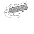
- FIG. 1 is a schematic perspective view of an electrode unit of the hydrogen-containing water generation device according to the present embodiment.
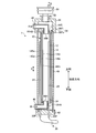
- FIG. 2 is a schematic sectional view of the hydrogen-containing water generator according to the present embodiment.
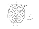
- FIG. 3 is a schematic enlarged view showing a part of the cathode part and the anode part according to the present embodiment.
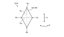
- FIG. 4 is a schematic enlarged view of the openings of the cathode section and the anode section according to the present embodiment.
- FIG. 5 is a sectional view taken along line AA of FIG.
- FIG. 6 is a schematic cross-sectional view illustrating a usage state of the hydrogen-containing water generation device according to the present embodiment.
- FIG. 1 is a schematic perspective view of an electrode unit of the hydrogen-containing water generation device according to the present embodiment.
- FIG. 2 is a schematic sectional view of the hydrogen-containing water generator according to the present embodiment.
- FIG. 3 is a schematic enlarged view showing a part of the cathode part and the
- FIG. 7 is a schematic cross-sectional view illustrating a usage state of the hydrogen-containing water generation device according to the comparative embodiment.
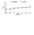
- FIG. 8 is a graph showing the hydrogen concentration in the comparative test.
- FIG. 9 is a graph showing the oxygen concentration in the comparative test.
- FIG. 10 is a graph showing the water temperature in the comparative test.
- FIG. 1 is a schematic perspective view of an electrode unit of the hydrogen-containing water generation device according to the present embodiment.
- FIG. 2 is a schematic sectional view of the hydrogen-containing water generator according to the present embodiment.
- the electrode unit 10 generates hydrogen-containing water R, which is hydrogen-containing water, from raw water W such as tap water using the electrolysis of water.
- the hydrogen-containing water R is water showing alkalinity.
- the electrode section 10 has a cathode section 12 and an anode section 14.
- the cathode section 12 and the anode section 14 are both cylindrical conductors.
- the anode section 14 is provided concentrically outside the cathode section 12 and is separated from the cathode section 12.
- the electrode section 10, more specifically, the cathode section 12 and the anode section 14 have a lower end side opening 10HA and an upper end side opening 10HB as openings at both ends, respectively.
- the distance between the cathode section 12 and the anode section 14 (referred to as a gap between electrodes) is maintained between the cathode section 12 and the anode section 14 by the lower spacer 54 and the upper spacer 56 (see FIG. 2).
- the size between the electrode gaps of the cathode section 12 and the anode section 14 is preferably 0.1 mm or more and 1 mm or less.
- the electrode unit 10 can generate a sufficient amount of hydrogen. If the size between the electrode gaps is in the above-described range, even if the voltage applied to the electrode unit 10 is relatively low, the electrode unit 10 dissolves a sufficient amount of hydrogen in the raw water W to remove a large amount of hydrogen. The dissolved hydrogen-containing water R can be generated. Further, if the amount of hydrogen dissolved in the hydrogen-containing water R is the same, the electrode unit 10 can suppress power consumption.
- the cathode 12 and the anode 14 are formed by plating platinum (Pt) on titanium (Ti).
- the plating may be, for example, platinum (Pt) -iridium (Ir) plating.
- the titanium is pure titanium.
- the cathode portion 12 and the anode portion 14 are not limited to those obtained by plating platinum on titanium, but are preferably made of a material (for example, vanadium (V)) that does not dissolve in the raw water W.
- both the cathode section 12 and the anode section 14 are plated, but only the anode section 14 may be plated, and the cathode section 12 may not be plated. Thereby, the manufacturing cost of the electrode unit 10 can be reduced.
- the cathode portion 12 and the anode portion 14 are net-like members in which a plurality of linear portions 16 intersect.
- the cathode section 12 has a plurality of openings 12H on the side.
- the anode section 14 has a plurality of openings 14H on the side. Portions surrounded by the plurality of linear portions 16 become openings 12H and 14H of the cathode portion 12 and the anode portion 14.
- the plurality of openings 12H of the cathode section 12 penetrate the side of the cathode section 12 in the thickness direction of the cathode section 12.
- the plurality of openings 14H of the anode part 14 penetrate the side part of the anode part 14 in the thickness direction of the anode part 14.
- the detailed shapes of the linear portions 16 of the cathode section 12 and the anode section 14 will be described later.
- the cathode portion 12 has a slit 12SL which extends in the longitudinal direction E, that is, the direction in which the cathode portion 12 which is a cylindrical member extends.
- the anode section 14 has a slit 14SL that extends in the longitudinal direction E, that is, the direction in which the anode section 14 that is a cylindrical member extends.
- the electrode unit 10 includes a plurality of restraining members 18 outside the anode unit 14.
- the restraining member 18 is, for example, a binding band made of resin, a metal wire, or the like.
- the restraining member 18 is preferably made of a material having high corrosion resistance and not dissolving in the raw water W.
- the restraining member 18 closes the slit 12SL of the cathode part 12 and the slit 14SL of the anode part 14, and restrains the cathode part 12 and the anode part 14 from the circumferential direction of the cathode part 12 and the anode part 14.
- the electrode section 10 can be easily disassembled into the cathode section 12 and the anode section 14, so that maintenance, inspection, repair, and replacement of parts are easy.
- Both the cathode power supply member 20 and the anode power supply member 22 are rod-shaped conductors.
- the cathode power supply member 20 is electrically connected to the cathode section 12.
- the cathode power supply member 20 is electrically connected to the cathode of the power supply 30.
- the anode power supply member 22 is electrically connected to the anode unit 14.
- the anode power supply member 22 is electrically connected to the anode of the power supply 30.
- the power supply 30 is a DC power supply.
- the cathode section 12 is electrically connected to the negative electrode of the power supply 30 via the cathode power supply member 20, and the anode section 14 is electrically connected to the positive electrode of the power supply 30 and the anode power supply member 22. Connected to.
- the cathode power supply member 20 is joined and attached to the cathode section 12 by joining means such as welding, for example, but is not limited to spot welding as long as it is electrically connected to the cathode section 12, and may be any joining means. May be used.
- the anode power supply member 22 is joined and attached to the anode section 14 by joining means such as welding, for example, but is not limited to spot welding as long as it is electrically connected to the anode section 14. May be used.
- the cathode power supply member 20 and the anode power supply member 22 are members formed by plating platinum on titanium, similarly to the cathode portion 12 and the anode portion 14.
- the plating may be, for example, platinum (Pt) -iridium (Ir) plating.
- the power supply member 20 for the cathode and the power supply member 22 for the anode are not limited to those obtained by plating platinum on titanium, as in the case of the cathode section 12 and the anode section 14. Is preferred.
- the cathode section 12 need not be plated, but in this case, the cathode power supply member 20 need not be plated.
- the hydrogen-containing water generator 1 includes an electrolytic cell 40, a lower base 42, an upper base 44, a water supply pipe 46, a drain pipe 48, a deaeration valve 50, A pipe 52.
- the electrolytic cell 40 is a transparent cylindrical cell.
- the electrode unit 10 is provided inside the electrolytic cell 40.
- the electrode unit 10 is arranged in a direction in which the longitudinal direction E is a vertical direction. Since the electrolytic cell 40 is provided transparently, a user can visually recognize the electrode unit 10, particularly, the anode unit 14 provided at a position facing the electrolytic cell 40 from the outside of the electrolytic cell 40.
- the lower end of the electrolytic cell 40 is covered and fixed by the lower base 42.
- the upper end of the electrolytic cell 40 is covered and fixed by the upper base 44.
- the lower base 42 fixes the lower end of the electrolytic cell 40, the cathode power supply member 20 and the anode power supply member 22.
- the cathode power supply member 20 and the anode power supply member 22 partially protrude below the lower end side openings 10HA of the cathode section 12 and the anode section 14.
- the lower base 42 is water-tightly penetrated by the projecting portion 20P of the cathode power supply member 20 and the projecting portion 22P of the anode power supply member 22.
- the lower base 42 fixes the cathode section 12 and the anode section 14 via the cathode power supply member 20 and the anode power supply member 22.
- the hydrogen-containing water generator 1 can supply power to the electrode unit 10 from outside the electrolytic cell 40 via the cathode power supply member 20 and the anode power supply member 22.
- the electrode section 10 is fixed to the lower base 42 and the electrolytic cell 40 via the cathode power supply member 20 and the anode power supply member 22.
- the upper base 44 is a cylindrical base whose upper end is closed. The upper base 44 fixes the upper end of the electrolytic cell 40.
- a joining pipe 52 that allows the deaeration valve 50 to communicate with the internal space 44S of the upper base 44 penetrates through the upper end of the upper base 44.
- the water supply pipe 46 is an L-shaped pipe for supplying raw water W to the electrolytic cell 40.
- the water supply pipe 46 is provided to penetrate a side portion of the electrolytic cell 40 in a watertight state.
- the anode power supply member 22 is illustrated on the left side of the anode unit 14, and the water supply pipe 46 and the anode power supply member 22 are illustrated to overlap with each other. 20 and an anode power supply member 22.
- the water supply section 46H which is an opening on the downstream end side of the water supply pipe 46, is provided inside the inner peripheral portion 12Si of the cathode section 12.
- the water supply unit 46H supplies water upward in the vertical direction.
- the water supply unit 46H supplies the raw water W from above the lower end side opening 10HA of the cathode unit 12.
- the drain pipe 48 is an L-shaped pipe for draining the hydrogen-containing water R in the electrolytic cell 40.
- the drain pipe 48 penetrates a side portion of the upper base 44 in a watertight manner through an internal space 44S of the upper base 44.
- a drain portion 48H which is an opening on the upstream end side of the drain pipe 48, is provided inside the inner peripheral portion 12Si of the cathode portion 12.
- the drainage section 48H drains water from above the water supply section 46H.
- the drainage part 48H takes in the hydrogen-containing water R below the upper end side opening 10HB of the cathode part 12 and discharges it to the outside of the electrolytic cell 40.
- the degassing valve 50 is fixed to the upper base 44 via the joining pipe 52.
- the deaeration valve 50 communicates with the internal space 44S of the upper base 44 via the joining pipe 52.
- the degassing valve 50 discharges the air G stored in the internal space 44S of the upper base 44.
- the degassing valve 50 releases the air G when the pressure inside the internal space 44S of the upper base 44 exceeds a predetermined value.
- the air G contains oxygen gas generated by an electrolysis reaction of water in the electrolytic cell 40.
- the lower spacer 54 has a cylindrical shape, and is disposed between the outer peripheral portion 12So of the cathode portion 12 and the inner peripheral portion 14Si of the anode portion 14 at the lower end side opening 10HA.
- the upper spacer 56 has a cylindrical shape and is disposed between the outer peripheral portion 12So of the cathode portion 12 and the inner peripheral portion 14Si of the anode portion 14 at the upper end side opening 10HB.
- the upper spacer 56 has an inner flange 56Fi that protrudes inward at the upper end.
- the inner flange portion 56Fi sets the distance between the electrode portion 10 and the drainage portion 48H to a predetermined distance.
- the upper spacer 56 has an outer flange 56Fo at the upper end.
- the outer flange portion 56Fo protrudes radially and outwardly, and is provided on the entire circumference in the circumferential direction.
- the outer collar portion 56 ⁇ / b> Fo sets the distance between the electrode portion 10 and the inner peripheral portion 40 ⁇ / b> Si of the electrolytic cell 40 to a predetermined distance.
- the electrolysis of the raw water W by the hydrogen-containing water generator 1 will be described.
- the electrode section 10 is immersed in the raw water W, a voltage is applied to the electrode section 10 by the power supply 30, and a potential difference is generated between the cathode section 12 and the anode section 14, so that the raw water W is electrolyzed to generate hydrogen-containing water R.
- the hydrogen-containing water generator 1 As described above, in the hydrogen-containing water generator 1, the generation of acidic wastewater is suppressed, and the hydrogen-containing water R flowing out of the drainage part 48H becomes neutral, for example, at a pH of 7 or more and 7.5 or less.
- the oxygen gas collects as bubbles on the outside of the anode section 14 and moves between the outer peripheral section 14So of the anode section 14 and the inner peripheral section 40Si of the electrolytic cell 40 to form an internal space 44S of the upper base 44, which is joined to the outer space 14Si. It is discharged to the hydrogen-containing water generator 1 through the pipe 52 and the deaeration valve 50.
- the ionized hydrogen ions H + generated in the anode part 14 are collected on the cathode part 12 side, and hydrogen gas bubbles are generated in the cathode part 12. These bubbles are minute bubbles having a diameter on the order of nanometers.
- the hydrogen-containing water generation device 1 supplies the raw water W from the water supply unit 46H and drains the hydrogen-containing water R from the drain unit 48H.
- the water supply part 46H and the drainage part 48H are provided inside the inner peripheral part 12Si of the cathode part 12.
- the raw water W flows vertically upward from the lower end side opening 10HA, and the hydrogen-containing water R flows out from the upper end side opening 10HB. That is, a water flow is generated from the lower side to the upper side inside the cathode portion 12.
- the hydrogen-containing water generator 1 can discharge the hydrogen-containing water R from the electrolytic cell 40 with priority. By preferentially discharging the hydrogen-containing water R from the electrolytic cell 40, the amount of dissolved oxygen in the water in the electrolytic tank 40 can be suppressed, and the hydrogen-containing water R can be suitably generated. Further, the water supply unit 46H supplies water upward in the vertical direction inside the inner peripheral part 12Si of the cathode part 12. That is, since the water supply unit 46H supplies water along the longitudinal direction E of the electrode unit 10, the raw water W supplied from the water supply unit 46H has a local distribution to the electrode unit 10 and is unlikely to collide with the raw water W. Electrolysis is possible.
- the drainage portion 48H drains from the inner peripheral portion 12Si of the cathode portion 12 above the water supply portion 46H, the hydrogen-containing water R drained from the drainage portion 48H has a local distribution to the electrode portion 10. As a result, turbulence does not easily occur, and uniform electrolysis can be performed.
- FIG. 3 is a schematic enlarged view showing a part of the cathode part and the anode part according to the present embodiment.
- FIG. 4 is a schematic enlarged view of the openings of the cathode section and the anode section according to the present embodiment.
- FIG. 5 is a sectional view taken along line AA of FIG.
- the openings 12H and the openings 14H of the cathode section 12 and the anode section 14 are rhombic.
- a first diagonal line TLl which is one diagonal line is longer than a second diagonal line TLs which is the other diagonal line.
- the opening 12H and the opening 14H have smaller angles at the tops Pa and Pb on the first diagonal line TLl than at the tops Pc and Pd on the second diagonal line TLs.
- the first diagonal line TLl extends in the direction in which the cathode section 12 and the anode section 14 extend, that is, in the longitudinal direction E.
- the second diagonal line TLs extends in the circumferential direction C of the cylindrical cathode 12 and anode 14.
- the cathode section 12 and the anode section 14 have the plurality of openings 12H and the openings 14H, the lines of electric force can be turned inside and outside through the openings 12H and the openings 14H. Thereby, since both surfaces of the cathode section 12 and the anode section 14 can be used for electrolysis, hydrogen can be efficiently generated. Further, the cathode portion 12 can reduce the wetting angle of the hydrogen bubbles generated by the cathode portion 12 by the opening 12H surrounded by the linear portion 16, so that the hydrogen bubbles can be released in a small state. That is, the adsorption force generated between the generated hydrogen and the surface of the cathode section 12 is close to point contact, and the surface tension is suppressed.
- the cathode section 12 reduces the hydrogen bubbles.
- the hydrogen-containing water R in which many hydrogen bubbles are dissolved can be generated by being separated in the state.
- the anode portion 14 can reduce the wetting angle of the oxygen bubbles generated by itself by the opening 14H surrounded by the linear portion 16, the oxygen bubbles can be quickly released. That is, the adsorption force generated between the generated oxygen and the surface of the anode section 14 is close to the point contact, and the surface tension is suppressed. As a result, the anode section 14 quickly removes oxygen bubbles. And oxygen bubbles can be efficiently released to the outside.
- the linear portions 16 of the cathode portion 12 and the anode portion 14 have a rectangular cross section (square in the example of FIG. 5).
- the cathode portion 12 can suppress the surface tension by further reducing the wetting angle of hydrogen bubbles by the corner portion 16T of the linear portion 16.
- the cathode portion 12 can release the hydrogen bubbles in a smaller state, and thus can generate the hydrogen-containing water R in which the smaller hydrogen bubbles are dissolved.
- the cathode portion 12 has the linear portion 16 having a rectangular cross section, the surface area available for generating hydrogen can be increased. Thereby, the efficiency of dissolving hydrogen in the raw water W in the cathode portion 12 is improved.
- corner portion 16T of the linear portion 16 of the anode portion 14 can further reduce the wetting angle of oxygen bubbles and suppress the surface tension.
- the anode portion 14 can quickly release the oxygen bubbles from the linear portion 16 and efficiently discharge the oxygen bubbles to the outside.
- FIG. 6 is a schematic cross-sectional view illustrating a usage state of the hydrogen-containing water generation device according to the present embodiment.
- the inside of the electrolytic cell 40 is filled with raw water W in advance.
- the water surface of the raw water W is at least above the drain portion 48H.
- a predetermined voltage is applied from the power supply 30, the above-described electrolysis reaction occurs in the electrode unit 10.
- the raw water W flows in from the water supply unit 46H and the water in the electrolytic cell 40 flows out from the drainage unit 48H, a flow of water from below to above inside the cathode unit 12 is generated. Water that does not flow out of the drainage section 48 ⁇ / b> H hits a water surface above the electrolytic cell 40 and flows outside the electrode section 10.
- a water flow is generated from above to below. That is, inside the electrolytic cell 40, water circulates inside and outside the electrode unit 10. The speed of the flow of water flowing from the lower side to the upper side inside the electrode unit 10 is higher than the speed of the flow of the water flowing from the upper side to the lower side outside the electrode unit 10.
- the raw water W While passing through the inside of the cathode section 12, the raw water W becomes hydrogen-containing water R including bubbles of hydrogen gas generated in the cathode section 12 by electrolysis, and flows out from the drain section 48H.
- Oxygen gas bubbles generated in the anode part 14 remain or descend between the outer peripheral part 14So of the anode part 14 and the inner peripheral part 40Si of the electrolytic cell 40 due to the flow of water flowing from above to below.
- the oxygen gas bubbles grow larger by being combined with each other, they rise against the flow of water and are discharged from the water surface.
- the oxygen gas discharged from the water surface is stored in the internal space 44S of the upper base 44.
- the air G containing oxygen gas is discharged to the hydrogen-containing water generation device 1 through the joining pipe 52 and the deaeration valve 50.
- the tubular cathode section 12 having the plurality of openings 12H on the side and the plurality of openings 14H on the side has the cathode section 12H.
- the anode part 14 can be visually recognized from the direction. That is, the user can easily confirm the deterioration state of the anode section 14. This allows the user to replace the electrode unit 10, particularly the anode unit 14, at an appropriate time, so that it is possible to prevent the hydrogen-containing water generator 1 from being stopped due to the failure of the electrode unit 10.
- the diameter, that is, the surface area is increased as compared with the conventional configuration provided inside the cathode portion 12, so that the current density is reduced and the anode portion 14 The durability is improved.
- the water supply section 46H for supplying water from one end side (the lower end side opening 10HA) of the cathode section 12 to the inside of the cathode section 12;
- a drain portion 48H for draining water (hydrogen-containing water R) inside the electrolytic cell 40 from the other end side (upper end side opening 10HB) of the inside of the cathode portion 12 where hydrogen gas is generated. Then, water flows from one side to the other.
- the hydrogen-containing water R can be preferentially discharged from the electrolytic cell 40, so that the amount of dissolved oxygen in the water in the electrolytic tank 40 can be suppressed, and the hydrogen-containing water R can be suitably generated.
- the cathode portion 12 extends along the vertical direction, a water supply portion 46H is provided on the vertically lower end side of the cathode portion 12, and the drainage portion 48H is provided on the vertically upper side of the cathode portion 12. Since it is provided on the end side, a flow of water from the lower side to the upper side is generated inside the cathode section 12. Thereby, the hydrogen-containing water R can be preferentially discharged from the electrolytic cell 40, so that the amount of dissolved oxygen in the water in the electrolytic tank 40 can be suppressed, and the hydrogen-containing water R can be suitably generated.
- the water supply unit 46H is inserted radially inside the cathode unit 12 and above the opening at the lower end (the lower end opening 10HA), the water that flows upward from below inside the cathode unit 12 is formed. Since the flow can be more suitably generated, the hydrogen-containing water R can be preferentially discharged from the electrolytic cell 40.
- the drainage portion 48H is inserted radially inside the cathode portion 12 and below the upper opening (upper opening 10HB), the water flowing upward from below inside the cathode portion 12 is formed. Since the flow can be more suitably generated, the hydrogen-containing water R can be preferentially discharged from the electrolytic cell 40.
- the oxygen gas generated in the anode part 14 can be preferably discharged to the outside.
- the spacers (the lower spacer 54 and the upper spacer 56) are arranged between the outer peripheral portion 12So of the cathode portion 12 and the inner peripheral portion 14Si of the anode portion 14, the distance between the cathode portion 12 and the anode portion 14 is increased. Can be suitably maintained.
- FIG. 7 is a schematic cross-sectional view illustrating a usage state of the hydrogen-containing water generation device according to the comparative embodiment.
- FIG. 8 is a graph showing the hydrogen concentration in the comparative test.
- FIG. 9 is a graph showing the oxygen concentration in the comparative test.
- FIG. 10 is a graph showing the water temperature in the comparative test.
- the application direction of the DC voltage is opposite to the configuration of the hydrogen-containing water generator 1 (see FIG. 6) according to the embodiment. That is, the electrode section 110 has an anode section inside and a cathode section outside.
- the cathode power supply member 20 is fixed to the outer peripheral portion 110So of the electrode portion 110.
- the anode power supply member 22 is fixed to the inner peripheral part 110Si of the electrode part 110.
- the water supply pipe 146 is an I-shaped pipe.
- the water supply pipe 146 is provided to penetrate a side portion of the electrolytic cell 40 in a watertight state.
- the water supply section 146H which is an opening on the downstream end side of the water supply pipe 146, is provided outside the outer peripheral section 110So of the electrode section 110.
- the water supply unit 146H supplies the raw water W in an inner circumferential direction.
- the drain pipe 148 is an I-shaped pipe.
- the drain pipe 148 is provided to penetrate the side of the electrolytic cell 40 in a watertight state.
- the drain 148H which is an opening on the upstream end side of the drain pipe 148, is provided outside the outer peripheral portion 110So of the electrode portion 110.
- the drain pipe 148 drains the hydrogen-containing water R toward the outer periphery.
- the degassing valve 50 communicates with the inside of the electrode unit 10 via the joining pipe 52.
- the degassing valve 50 releases air G containing oxygen gas generated by the electrolysis reaction of water in the electrolytic cell 40.
- the hydrogen-containing water generator 2 can preferentially discharge oxygen gas from the electrolytic cell 40.
- the amount of dissolved oxygen in water in the electrolytic cell 40 is suppressed, and hydrogen-containing water R is generated.
- a flow of water that flows upward from below is generated inside and outside the electrode unit 110. That is, inside the electrolytic cell 40 of the hydrogen-containing water generator 2, the circulation of water unlike the hydrogen-containing water generator 1 does not occur inside and outside the electrode unit 10.
- FIGS. 8, 9 and 10 show the hydrogen concentration (ppm) and the oxygen concentration (ppm) of the hydrogen-containing water R discharged from the drain pipe 48 of the hydrogen-containing water generator 1 and the drain pipe 148 of the hydrogen-containing water generator 2. ) And water temperature (° C.).
- ppm hydrogen concentration
- ppm oxygen concentration
- ppm oxygen concentration
- the hydrogen-containing water generator 1 of the present embodiment has substantially the same performance as the hydrogen-containing water generator 2.
- the hydrogen-containing water generator 1 can easily check the deterioration state of the anode unit 14 while having substantially the same performance as the hydrogen-containing water generator 2.
- the shapes of the cathode part 12, the anode part 14, and the electrolytic cell 40 are all cylindrical, but are not limited thereto, and may be any shape as long as it is cylindrical.
- the electrode section 10 may not have the lower end side opening 10HA and the upper end side opening 10HB, or may have only one of the lower end side opening 10HA and the upper end side opening 10HB. May be.
- the water supply unit 46H supplies the raw water W upward in the vertical direction toward the lower end of the electrode unit 10. The raw water W passes through the openings 12H and 14H and flows into the inside of the cathode unit 12.
- the electrode section 10 is fixed to the lower base 42 and the electrolytic cell 40 via the cathode power supply member 20 and the anode power supply member 22, but the fixing method is not particularly limited. Further, in the present embodiment, by arranging the cylindrical cathode portion 12, the anode portion 14, and the electrolytic cell 40 in a direction in which the axial direction is parallel to the vertical direction, the flow of water in the electrolytic cell 40 is preferably achieved. It can be controlled, and the hydrogen-containing water R can be suitably discharged. Note that the directions of the cathode 12, anode 14, and electrolytic cell 40 are not limited to directions in which the axial direction is parallel to the vertical direction, but are preferably arranged along the axial direction.
- the end of the cathode power supply member 20 opposite to the protruding portion 20P extends to the vicinity of the upper end side opening 10HB.
- the height may be equal to or less than half the dimension of the cathode section 12 in the longitudinal direction E.
- the anode power supply member 22 has an end opposite to the protruding portion 22P extending to near the upper end side opening 10HB, but the length of the portion of the anode power supply member 22 attached to the cathode section 12 is the cathode section.
- the length may be equal to or less than half of the length in the longitudinal direction E.
- the electrode section 10 may be provided with a cathode support member having the same shape as the cathode power supply member 20 on the side opposite to the side on which the cathode power supply member 20 is provided.
- the electrode unit 10 may be provided with an anode support member having the same shape as the anode power supply member 22 on the side opposite to the side on which the anode power supply member 22 is provided.
- the anode support member and the cathode support member may be the same material as the cathode power supply member 20 and the anode power supply member 22, or may be different materials.
- the negative electrode power supply member 20 does not have to have a rod-like shape as in the present embodiment, and may have an arbitrary shape.
- the cathode power supply member 20 is not limited to being connected to the cathode section 12 at the lower end side opening 10HA, but may be connected at any location as long as it is electrically connected to the cathode section 12 as a conductor.
- the anode power supply member 22 does not have to have a rod-like shape as in the present embodiment, and may have an arbitrary shape.
- the anode power supply member 22 is not limited to being connected to the anode section 14 at the lower end side opening 10HA, but may be connected at any location as long as it is electrically connected to the anode section 14 as a conductor. .
- the water supply pipe 46 is an L-shaped pipe provided through the side portion of the electrolytic cell 40, but is an I-shaped pipe provided through the lower base 42. Is also good.
- the water supply pipe 46 may have any shape as long as the water supply part 46H, which is an opening on the downstream end side, supplies water upward in the vertical direction inside the inner peripheral part 12Si of the cathode part 12. Absent.
- the drain pipe 48 is an L-shaped pipe provided through the side of the upper base 44, but may be an I-shaped pipe provided through the upper part of the upper base 44. Good.
- the drain pipe 48 may have any shape as long as the drain section 48H, which is an opening on the upstream end side, drains from the inside of the inner peripheral portion 12Si of the cathode section 12 above the water supply section 46H.
- the joining pipe 52 may be provided at any position and may have any shape as long as the joining pipe 52 allows the deaeration valve 50 and the internal space 44S of the upper base 44 to communicate with each other.
- the drain pipe 48 is an I-shaped pipe provided to penetrate the upper part of the upper base 44
- the joining pipe 52 may be provided at a position above the upper base 44 so as not to overlap the drain pipe 48.
- the upper base 44 may be provided integrally with the upper spacer 56.
- the cathode section 12 and the anode section 14 are provided separately from each other with the lower spacer 54 and the upper spacer 56 interposed therebetween. May be interposed.
- the insulator contacts, for example, the outer peripheral portion 12So of the cathode portion 12 and the inner peripheral portion 14Si of the anode portion 14.
- the present invention is not limited by the present embodiment.
- the above-mentioned components include those that can be easily assumed by those skilled in the art, those that are substantially the same, and those that are in the so-called equivalent range. Further, the components described above can be appropriately combined. Furthermore, various omissions, substitutions, or changes of the components can be made without departing from the spirit of the present embodiment.
- Electrode unit 10 H Lower opening side 10HB Upper opening side 12 Cathode unit 12H Opening 12SL Slit 12Si Inner periphery 12So Outer periphery 14 Anode unit 14H opening 14SL Slit 14Si Inner periphery 14So Outer periphery Part 16 Linear portion 18 Restriction member 20 Power supply member for cathode 20P Projection portion 22 Power supply member for anode 22P Projection portion 30 Power supply 40 Electrolyte tank 40Si Inner peripheral portion 42 Lower base 44 Upper base 44S Internal space 46 Water supply pipe 46H Water supply Part 48 Drainage pipe 48H Drainage part 50 Deaeration valve 52 Joining pipe 54 Lower spacer 56 Upper spacer 56Fi Inner flange part 56Fo Outer flange part 110 Electrode part 110Si Inner peripheral part 110So Outer peripheral part 146 Water supply pipe 146H Water supply part 148 Drainage pipe 148H Drainage part E longitudinal direction C circumferential direction TL The first diagonal TLs second diagonal W raw R hydrogen-containing
Landscapes
- Chemical & Material Sciences (AREA)
- Chemical Kinetics & Catalysis (AREA)
- Electrochemistry (AREA)
- General Chemical & Material Sciences (AREA)
- Life Sciences & Earth Sciences (AREA)
- Hydrology & Water Resources (AREA)
- Engineering & Computer Science (AREA)
- Environmental & Geological Engineering (AREA)
- Water Supply & Treatment (AREA)
- Organic Chemistry (AREA)
- Water Treatment By Electricity Or Magnetism (AREA)
- Electrolytic Production Of Non-Metals, Compounds, Apparatuses Therefor (AREA)
Abstract
Description
10 電極部
10HA 下端部側開口部
10HB 上端部側開口部
12 陰極部
12H 開口
12SL スリット
12Si 内周部
12So 外周部
14 陽極部
14H 開口
14SL スリット
14Si 内周部
14So 外周部
16 線状部分
18 拘束部材
20 陰極用給電部材
20P 突出部分
22 陽極用給電部材
22P 突出部分
30 電源
40 電解槽
40Si 内周部
42 下側基台
44 上側基台
44S 内部空間
46 給水管
46H 給水部
48 排水管
48H 排水部
50 脱気弁
52 接合管
54 下部スペーサ
56 上部スペーサ
56Fi 内鍔部
56Fo 外鍔部
110 電極部
110Si 内周部
110So 外周部
146 給水管
146H 給水部
148 排水管
148H 排水部
E 長手方向
C 周方向
TLl 第1対角線
TLs 第2対角線
W 原水
R 水素含有水
G 空気
Claims (6)
- 側部に複数の開口を有する筒状の陰極部と、
側部に複数の開口を有し、前記陰極部の径方向外側に設けられる筒状の陽極部と、
前記陰極部及び前記陽極部が内部に設けられる透明な筒状の電解槽と、
前記陰極部の一方の端部側から前記陰極部の内部に給水する給水部と、
前記陰極部の他方の端部側から前記電解槽内部の水を排水する排水部と、
を含む水素含有水生成装置。 - 前記陰極部は、鉛直方向に沿って延在し、
前記給水部は、前記陰極部の鉛直方向下側の端部側に設けられ、
前記排水部は、前記陰極部の鉛直方向上側の端部側に設けられる請求項1に記載の水素含有水生成装置。 - 前記給水部は、前記陰極部の径方向内側、かつ、下端側の開口より上方に挿入される請求項2に記載の水素含有水生成装置。
- 前記排水部は、前記陰極部の径方向内側、かつ、上端側の開口より下方に挿入される請求項2又は3に記載の水素含有水生成装置。
- 前記電解槽の空気を排出する脱気弁を含む請求項1から4のいずれか一項に記載の水素含有水生成装置。
- 前記陰極部の外周部と前記陽極部の内周部との間にスペーサが配置される請求項1から5のいずれか一項に記載の水素含有水生成装置。
Priority Applications (4)
| Application Number | Priority Date | Filing Date | Title |
|---|---|---|---|
| JP2018565434A JP6593558B1 (ja) | 2018-08-29 | 2018-08-29 | 水素含有水生成装置 |
| PCT/JP2018/031998 WO2020044472A1 (ja) | 2018-08-29 | 2018-08-29 | 水素含有水生成装置 |
| US17/269,482 US11542182B2 (en) | 2018-08-29 | 2018-08-29 | Hydrogen-containing water generator |
| KR1020217005339A KR20210035255A (ko) | 2018-08-29 | 2018-08-29 | 수소 함유수 생성 장치 |
Applications Claiming Priority (1)
| Application Number | Priority Date | Filing Date | Title |
|---|---|---|---|
| PCT/JP2018/031998 WO2020044472A1 (ja) | 2018-08-29 | 2018-08-29 | 水素含有水生成装置 |
Publications (1)
| Publication Number | Publication Date |
|---|---|
| WO2020044472A1 true WO2020044472A1 (ja) | 2020-03-05 |
Family
ID=68314062
Family Applications (1)
| Application Number | Title | Priority Date | Filing Date |
|---|---|---|---|
| PCT/JP2018/031998 Ceased WO2020044472A1 (ja) | 2018-08-29 | 2018-08-29 | 水素含有水生成装置 |
Country Status (4)
| Country | Link |
|---|---|
| US (1) | US11542182B2 (ja) |
| JP (1) | JP6593558B1 (ja) |
| KR (1) | KR20210035255A (ja) |
| WO (1) | WO2020044472A1 (ja) |
Cited By (2)
| Publication number | Priority date | Publication date | Assignee | Title |
|---|---|---|---|---|
| JP7238076B1 (ja) | 2021-11-09 | 2023-03-13 | 株式会社日本トリム | 電解水生成装置 |
| JP7494699B2 (ja) | 2020-10-23 | 2024-06-04 | 中国電力株式会社 | 水素含有水生成装置及び水素含有水生成方法 |
Families Citing this family (1)
| Publication number | Priority date | Publication date | Assignee | Title |
|---|---|---|---|---|
| CN115349089B (zh) * | 2020-03-23 | 2026-04-14 | 国立研究开发法人物质材料研究机构 | 基本气味选定方法、通过基本气味的组合来表现、提示或合成气味的方法及装置 |
Citations (5)
| Publication number | Priority date | Publication date | Assignee | Title |
|---|---|---|---|---|
| JP2007144305A (ja) * | 2005-11-28 | 2007-06-14 | Sashuu Sangyo:Kk | 洗浄液およびその製造方法 |
| JP2008043891A (ja) * | 2006-08-17 | 2008-02-28 | Nittetsu Mining Co Ltd | 密閉筒状電解装置 |
| JP2010088973A (ja) * | 2008-10-03 | 2010-04-22 | Chugoku Electric Manufacture Co Ltd | 水素含有電解水生成装置及び給湯設備 |
| JP2011525146A (ja) * | 2008-06-19 | 2011-09-15 | テナント カンパニー | 一定出力をもつ電解スケール除去方法 |
| JP2016022469A (ja) * | 2014-07-24 | 2016-02-08 | 中国電力株式会社 | 水素含有水生成装置及び入浴設備 |
Family Cites Families (13)
| Publication number | Priority date | Publication date | Assignee | Title |
|---|---|---|---|---|
| US3378479A (en) * | 1964-06-26 | 1968-04-16 | Simplex Mfg Co | Electrolytic cell and chlorinating system using same |
| US3558465A (en) * | 1964-06-26 | 1971-01-26 | Simplex Mfg Co | Electrolytic cell |
| GB2238059A (en) * | 1989-11-17 | 1991-05-22 | Command International Inc | Electrolytic gas generating apparatus for producing a combustible mixture of hydrogen and oxygen by electrolysis of water for particular use in gas welding |
| FI115904B (fi) * | 2002-01-25 | 2005-08-15 | Bcde Group Waste Man Ltd Oy | Menetelmä ja laite epäpuhtauksien poistamiseksi jätevedestä elektroflotaatiolla |
| KR100550219B1 (ko) | 2004-02-24 | 2006-02-08 | 위니아만도 주식회사 | 이온수기용 분리형 전해조 |
| WO2005113449A1 (ja) * | 2004-05-20 | 2005-12-01 | Elm Inc. | 水浄化装置 |
| JP4233545B2 (ja) * | 2004-06-10 | 2009-03-04 | パナソニック株式会社 | リンの除去装置 |
| JP2006198562A (ja) * | 2005-01-24 | 2006-08-03 | Eretekkusu Engineering Kk | 電極装置および電解槽 |
| US8075750B2 (en) * | 2009-02-17 | 2011-12-13 | Mcalister Technologies, Llc | Electrolytic cell and method of use thereof |
| JP5688109B2 (ja) * | 2013-01-31 | 2015-03-25 | 中国電機製造株式会社 | 水素含有水生成用電極の製造方法及び水素含有水生成用電極 |
| JP5688106B2 (ja) | 2013-01-31 | 2015-03-25 | 中国電機製造株式会社 | 水素含有水生成用電極及び水素含有水生成装置 |
| JP5688104B2 (ja) | 2013-01-31 | 2015-03-25 | 中国電機製造株式会社 | 水素含有水生成用電極及び水素含有水生成装置 |
| KR101781465B1 (ko) | 2016-06-21 | 2017-10-23 | 주식회사 케이엠피 | 감압시 기체만 방출되는 휴대용 수소수 생성용기 |
-
2018
- 2018-08-29 KR KR1020217005339A patent/KR20210035255A/ko not_active Ceased
- 2018-08-29 WO PCT/JP2018/031998 patent/WO2020044472A1/ja not_active Ceased
- 2018-08-29 JP JP2018565434A patent/JP6593558B1/ja active Active
- 2018-08-29 US US17/269,482 patent/US11542182B2/en active Active
Patent Citations (5)
| Publication number | Priority date | Publication date | Assignee | Title |
|---|---|---|---|---|
| JP2007144305A (ja) * | 2005-11-28 | 2007-06-14 | Sashuu Sangyo:Kk | 洗浄液およびその製造方法 |
| JP2008043891A (ja) * | 2006-08-17 | 2008-02-28 | Nittetsu Mining Co Ltd | 密閉筒状電解装置 |
| JP2011525146A (ja) * | 2008-06-19 | 2011-09-15 | テナント カンパニー | 一定出力をもつ電解スケール除去方法 |
| JP2010088973A (ja) * | 2008-10-03 | 2010-04-22 | Chugoku Electric Manufacture Co Ltd | 水素含有電解水生成装置及び給湯設備 |
| JP2016022469A (ja) * | 2014-07-24 | 2016-02-08 | 中国電力株式会社 | 水素含有水生成装置及び入浴設備 |
Cited By (3)
| Publication number | Priority date | Publication date | Assignee | Title |
|---|---|---|---|---|
| JP7494699B2 (ja) | 2020-10-23 | 2024-06-04 | 中国電力株式会社 | 水素含有水生成装置及び水素含有水生成方法 |
| JP7238076B1 (ja) | 2021-11-09 | 2023-03-13 | 株式会社日本トリム | 電解水生成装置 |
| JP2023070528A (ja) * | 2021-11-09 | 2023-05-19 | 株式会社日本トリム | 電解水生成装置 |
Also Published As
| Publication number | Publication date |
|---|---|
| KR20210035255A (ko) | 2021-03-31 |
| US20210300798A1 (en) | 2021-09-30 |
| JPWO2020044472A1 (ja) | 2020-09-10 |
| JP6593558B1 (ja) | 2019-10-23 |
| US11542182B2 (en) | 2023-01-03 |
Similar Documents
| Publication | Publication Date | Title |
|---|---|---|
| CN103917694B (zh) | 管型电解装置 | |
| JP6593558B1 (ja) | 水素含有水生成装置 | |
| JP6187861B2 (ja) | 電解電極デバイスおよび当該電解電極デバイスを備える電解水生成装置 | |
| KR20200134267A (ko) | 폐수 처리를 위한 바이폴라 전극을 구비한 전해조 | |
| JP6128073B2 (ja) | 水素含有水生成装置及び入浴設備 | |
| JP6132234B2 (ja) | 電解水生成装置 | |
| KR101474868B1 (ko) | 전해액 확산 및 가스 배출 효율이 향상된 수전해조 | |
| JP2017110279A (ja) | 過酸化水素生成装置 | |
| US10494275B2 (en) | Electrolysis module | |
| ES2795690T3 (es) | Electrodo para un procedimiento de electrólisis | |
| JP2009228041A (ja) | 電解装置および電解方法 | |
| KR101481327B1 (ko) | 복극식 전기분해 반응기 | |
| KR101412721B1 (ko) | 전해모듈 | |
| KR101867370B1 (ko) | 휴대형 수소수 제조 장치 | |
| JP7434828B2 (ja) | 水素含有水生成装置、及び電極交換時期の予測方法 | |
| JP7443746B2 (ja) | 水素含有水生成システム、及び水素含有水生成方法 | |
| KR20150097104A (ko) | 산성수 전해조 | |
| ES2967558B2 (es) | Unidad de electro-absorción para la eliminación de compuestos orgánicos volátiles y odorantes en corrientes gasesosas | |
| JP7494699B2 (ja) | 水素含有水生成装置及び水素含有水生成方法 | |
| JP2025002458A (ja) | 電解水生成装置 | |
| JP2021098162A (ja) | 水素含有水生成装置用電解槽及び水素含有水生成方法 | |
| JP2012255200A (ja) | 電解装置及び電解方法 | |
| JP2025002926A (ja) | 水電解装置及び水電解装置の組み立て構造 | |
| JP5791841B1 (ja) | オゾン水製造装置 | |
| TH8593A3 (th) | อุปกรณ์การบำบัดน้ำด้วยเซลล์ไฟฟ้าแบบท่อในท่อที่มีลักษณะการไหลของน้ำ แบบซิกแซกระหว่างขั้วแบบโมโนโพล่าและประกอบด้วยเครื่องกวนในเส้นท่อแบบนิ่ง |
Legal Events
| Date | Code | Title | Description |
|---|---|---|---|
| ENP | Entry into the national phase |
Ref document number: 2018565434 Country of ref document: JP Kind code of ref document: A |
|
| 121 | Ep: the epo has been informed by wipo that ep was designated in this application |
Ref document number: 18931487 Country of ref document: EP Kind code of ref document: A1 |
|
| ENP | Entry into the national phase |
Ref document number: 20217005339 Country of ref document: KR Kind code of ref document: A |
|
| NENP | Non-entry into the national phase |
Ref country code: DE |
|
| 122 | Ep: pct application non-entry in european phase |
Ref document number: 18931487 Country of ref document: EP Kind code of ref document: A1 |