WO2020040154A1 - Production method for prepreg, prepreg tape, and fiber reinforced composite material, and prepreg production device - Google Patents
Production method for prepreg, prepreg tape, and fiber reinforced composite material, and prepreg production device Download PDFInfo
- Publication number
- WO2020040154A1 WO2020040154A1 PCT/JP2019/032496 JP2019032496W WO2020040154A1 WO 2020040154 A1 WO2020040154 A1 WO 2020040154A1 JP 2019032496 W JP2019032496 W JP 2019032496W WO 2020040154 A1 WO2020040154 A1 WO 2020040154A1
- Authority
- WO
- WIPO (PCT)
- Prior art keywords
- fiber sheet
- matrix resin
- reinforcing fiber
- prepreg
- sheet
- Prior art date
Links
Images


Classifications
-
- B—PERFORMING OPERATIONS; TRANSPORTING
- B29—WORKING OF PLASTICS; WORKING OF SUBSTANCES IN A PLASTIC STATE IN GENERAL
- B29B—PREPARATION OR PRETREATMENT OF THE MATERIAL TO BE SHAPED; MAKING GRANULES OR PREFORMS; RECOVERY OF PLASTICS OR OTHER CONSTITUENTS OF WASTE MATERIAL CONTAINING PLASTICS
- B29B15/00—Pretreatment of the material to be shaped, not covered by groups B29B7/00 - B29B13/00
- B29B15/08—Pretreatment of the material to be shaped, not covered by groups B29B7/00 - B29B13/00 of reinforcements or fillers
- B29B15/10—Coating or impregnating independently of the moulding or shaping step
- B29B15/12—Coating or impregnating independently of the moulding or shaping step of reinforcements of indefinite length
- B29B15/122—Coating or impregnating independently of the moulding or shaping step of reinforcements of indefinite length with a matrix in liquid form, e.g. as melt, solution or latex
- B29B15/125—Coating or impregnating independently of the moulding or shaping step of reinforcements of indefinite length with a matrix in liquid form, e.g. as melt, solution or latex by dipping
-
- B—PERFORMING OPERATIONS; TRANSPORTING
- B29—WORKING OF PLASTICS; WORKING OF SUBSTANCES IN A PLASTIC STATE IN GENERAL
- B29B—PREPARATION OR PRETREATMENT OF THE MATERIAL TO BE SHAPED; MAKING GRANULES OR PREFORMS; RECOVERY OF PLASTICS OR OTHER CONSTITUENTS OF WASTE MATERIAL CONTAINING PLASTICS
- B29B11/00—Making preforms
- B29B11/14—Making preforms characterised by structure or composition
- B29B11/16—Making preforms characterised by structure or composition comprising fillers or reinforcement
-
- B—PERFORMING OPERATIONS; TRANSPORTING
- B29—WORKING OF PLASTICS; WORKING OF SUBSTANCES IN A PLASTIC STATE IN GENERAL
- B29K—INDEXING SCHEME ASSOCIATED WITH SUBCLASSES B29B, B29C OR B29D, RELATING TO MOULDING MATERIALS OR TO MATERIALS FOR MOULDS, REINFORCEMENTS, FILLERS OR PREFORMED PARTS, e.g. INSERTS
- B29K2063/00—Use of EP, i.e. epoxy resins or derivatives thereof, as moulding material
-
- B—PERFORMING OPERATIONS; TRANSPORTING
- B29—WORKING OF PLASTICS; WORKING OF SUBSTANCES IN A PLASTIC STATE IN GENERAL
- B29K—INDEXING SCHEME ASSOCIATED WITH SUBCLASSES B29B, B29C OR B29D, RELATING TO MOULDING MATERIALS OR TO MATERIALS FOR MOULDS, REINFORCEMENTS, FILLERS OR PREFORMED PARTS, e.g. INSERTS
- B29K2307/00—Use of elements other than metals as reinforcement
- B29K2307/04—Carbon
Definitions
- the present invention relates to a method for producing a prepreg, a prepreg tape and a fiber-reinforced composite material, and a prepreg production apparatus, and more particularly to a method and an apparatus for uniformly impregnating a reinforcing fiber sheet with a matrix resin.
- Fiber reinforced composite material which is a matrix resin containing thermoplastic resin and thermosetting resin reinforced with reinforcing fibers, is a material for aviation and space, automotive material, industrial material, pressure vessel, building material, housing, medical equipment. It is used in various fields such as applications and sports. Particularly when high mechanical properties and lightness are required, carbon fiber reinforced composite materials (CFRP) are widely and suitably used. On the other hand, when cost is prioritized over mechanical properties and light weight, a glass fiber reinforced composite material (GFRP) may be used. In the FRP, a reinforcing fiber bundle is impregnated with a matrix resin to obtain an intermediate base material, which is laminated and molded, and when a thermosetting resin is used, is thermoset to produce a member made of FRP.
- CFRP carbon fiber reinforced composite materials
- GFRP glass fiber reinforced composite material
- the two-dimensional sheet-like material is more often used as an intermediate substrate of FRP than a one-dimensional strand or roving-like material when producing a member. It is widely used from the viewpoint of lamination efficiency and moldability.
- narrow-width tape-like intermediate substrates are preferably used here.
- the narrow tape-shaped intermediate substrate can be obtained by slicing a wide sheet-shaped intermediate substrate at a desired width, or by directly impregnating a narrow reinforcing fiber sheet with a matrix resin.
- a prepreg obtained by impregnating a reinforcing fiber sheet with a matrix resin is widely used.
- the reinforcing fiber sheet used for the prepreg include a UD base material in which reinforcing fibers are arranged in one direction and in a sheet form, and a reinforcing fiber fabric which is a woven fabric arranged in multiple directions. Particularly when the mechanical properties are prioritized, the UD base material is often used.
- the hot melt method which is one of the prepreg manufacturing methods, involves melting a matrix resin, coating it on a release sheet, and sandwiching this on the upper and lower surfaces of a reinforcing fiber sheet to produce a laminated structure. This impregnates the inside of the reinforcing fiber sheet with the matrix resin. This method has a problem that the number of steps is large, the production speed cannot be increased, and the cost is high.
- Patent Document 2 a method for simultaneously forming a coating film on both sides of a sheet material is described in Patent Document 2.
- the sheet material is passed through a web guide. After that, coating is performed with a pipe type doctor.
- Patent Literature 3 Patent Literature 4, etc.
- Patent Document 3 a tape-like reinforcing fiber is passed through a crosshead (FIG. 2 of Patent Document 3), and a resin is applied to a tape-like reinforcing fiber bundle immediately before a linear die portion in the crosshead.
- Patent Document 4 discloses that a plurality of band-shaped reinforcing fiber bundles are separately introduced into a die filled with a molten thermoplastic resin, opened, impregnated, and laminated by a fixed guide (for example, a squeeze bar). It is described that the sheet-shaped prepreg is pulled out from a die.
- Patent Document 1 can only produce strands or rovings, and cannot be applied to the production of sheet-like prepregs that are the subject of the present invention.
- a fluid of a thermoplastic resin is applied to the strand or the side surface of the roving-like reinforcing fiber bundle to generate turbulent flow positively in the conical flow path. It is considered that this is intended to partially disturb the arrangement of the reinforcing fiber bundle and allow the matrix resin to flow, but when this concept is applied to the reinforcing fiber sheet, the arrangement of the reinforcing fibers is disturbed, and the quality of the prepreg is reduced. It is thought that not only does the FRP decrease, but also the mechanical properties of the FRP decrease.
- the sheet-like material in Patent Document 2 is a film, cloth, paper, foil, a punching plate, a net-like sheet material, and the like, and the reinforcing fiber sheet that is the object of the present invention is not intended. If the technique of Patent Literature 2 is applied to a reinforcing fiber sheet made of carbon fibers, it is considered that fluff is generated by rubbing with a web guide, and the running of the reinforcing fiber sheet becomes difficult. Further, the technique of Patent Document 2 is coating of a resin, and impregnation is not intended.
- An object of the present invention is to reduce the generation of fluff in the prepreg production method, to enable continuous production without clogging of fluff, and to impregnate the reinforcing fiber sheet with a matrix resin efficiently, thereby increasing the production speed. It is another object of the present invention to provide a method and an apparatus for producing a prepreg, which is possible, and further suppresses the obtained reinforcing fiber sheet from being broken or the like and has a uniform basis weight.
- the method for producing a prepreg of the present invention that solves the above-described problem is to pass the reinforcing fiber sheet substantially vertically downward inside the application section where the matrix resin is stored, and to apply the matrix resin to the reinforcing fiber sheet.
- a step of obtaining a matrix resin-impregnated reinforced fiber sheet a method for producing a prepreg including a step of heating the matrix resin-impregnated reinforced fiber sheet in a non-contact manner,
- the application unit includes a liquid reservoir and a constricted portion that are communicated with each other, the liquid reservoir has a portion having a continuously decreasing cross-sectional area along a running direction of the reinforcing fiber sheet, and the constricted portion has a slit shape.
- the constriction has a slit-shaped cross-section and a cross-section smaller than the upper surface of the liquid reservoir, and is subjected to additional impregnation from the outlet of the application part.
- a liquid reservoir having a portion in which the matrix resin is stored and having a cross-sectional area continuously decreasing vertically downward; a constricted portion having a slit-shaped outlet communicating with a lower end of the liquid reservoir;
- a method for producing a prepreg tape of the present invention is characterized in that the prepreg obtained by the above-described method for producing a prepreg is slit.
- the method for producing a fiber-reinforced composite material of the present invention is characterized in that the prepreg obtained by the above-described method for producing a prepreg or the prepreg tape obtained by the above-described method for producing a prepreg tape is cured.
- FIG. 1 is a schematic cross-sectional view illustrating a prepreg manufacturing method according to an embodiment of a first manufacturing method of the present invention. It is a schematic cross section showing the manufacturing method of the prepreg concerning the embodiment of the 2nd manufacturing method of the present invention.
- FIG. 2 is a detailed transverse cross-sectional view in which the application section and the additional impregnation device 19 in FIG. 1 are enlarged.
- FIG. 2A is a detailed cross-sectional view when a release sheet 3 is used in another embodiment different from FIG. 2A. It is a schematic cross section showing the manufacturing method of the prepreg concerning the embodiment of the 3rd manufacturing method of the present invention.
- FIG. 1 is a schematic cross-sectional view illustrating a prepreg manufacturing method according to an embodiment of a first manufacturing method of the present invention. It is a schematic cross section showing the manufacturing method of the prepreg concerning the embodiment of the 2nd manufacturing method of the present invention.
- FIG. 2 is a detailed transverse cross-sectional view in
- FIG. 2 is an enlarged detailed cross-sectional view of a coating section in FIG. 1.
- FIG. 5 is a bottom view of the application unit in FIG. 4 when viewed from the direction of A in FIG. 4.
- FIG. 5 is a cross-sectional view illustrating a structure inside the application section when the application section in FIG. 4 is viewed from a direction B in FIG. 4. It is sectional drawing showing the flow of the matrix resin 2 in the clearance gap 26 in FIG. 6a.
- FIG. 4 is a detailed cross-sectional view in which a coating section of FIG. 3 is enlarged.
- FIG. 4 is a detailed cross-sectional view of the reinforcing fiber sheet 1a that contacts a bar 35 inside the liquid reservoir 22.
- FIG. 14 is a detailed cross-sectional view of a bar 35 of another embodiment. It is a figure showing an example of installation of a width regulation mechanism.
- FIG. 8 is a detailed cross-sectional view illustrating a structure inside the application section when the application section in FIG. 7 is viewed from a direction B in the figure.
- FIG. 12 is a detailed cross-sectional view illustrating an internal structure of a coating section 41 of an embodiment different from FIG. 11. It is a figure showing an example which provides width control members at both ends of a bar. It is a figure which shows the width
- FIG. 13 is a detailed cross-sectional view illustrating an internal structure of a coating section 42 of an embodiment different from FIG. 11.
- FIG. 11 is a detailed cross-sectional view illustrating an internal structure of a coating section 42 of an embodiment different from FIG. 11.
- FIG. 5 is a detailed cross-sectional view of a coating unit 20b according to another embodiment different from FIG. 4.
- FIG. 17 is a detailed cross-sectional view of a coating unit 20c according to another embodiment different from FIG. 16.
- FIG. 17 is a detailed cross-sectional view of a coating unit 20d according to another embodiment different from FIG. 16.
- FIG. 17 is a detailed cross-sectional view of a coating section 20e of another embodiment different from FIG.
- FIG. 4 is a detailed cross-sectional view of a coating unit 30 according to an embodiment different from the present invention.
- It is a schematic diagram showing an example of an embodiment of a prepreg manufacturing process using the first manufacturing method of the present invention. It is the schematic of the example of another prepreg manufacturing process using the 2nd manufacturing method of this invention.
- the present invention discloses three new prepreg manufacturing methods. These production methods obtain a matrix resin-impregnated reinforced fiber sheet in which the matrix resin is applied to the reinforced fiber sheet by passing the reinforced fiber sheet substantially vertically downward inside the application portion in which the matrix resin is stored. In common. In this production method, the following three production methods are used in order to further improve the degree of impregnation of the obtained prepreg.
- the coating device 100 is provided between the transport rolls 13 and 14, which are traveling mechanisms for traveling the reinforcing fiber sheet 1a substantially vertically downward Z, and is a coating mechanism in which the matrix resin 2 is stored.
- An application unit 20 is provided. Further, before and after the coating apparatus 100, a plurality of creels 11 for unwinding the reinforcing fibers 1 and a reinforcing fiber sheet 1a in which the unwound reinforcing fibers 1 are arranged in one direction (in FIG. 1, arranged in the depth direction of the paper). And a winding device 17 for the prepreg 1c.
- the coating device 100 is provided with a matrix resin supply device (not shown).
- an additional impregnation device 19 is provided between the coating unit 20 and the transport roll 14.
- this is a non-contact heating device.
- the release sheet 3 can be provided to the prepreg 1c additionally impregnated by the non-contact heating device. In FIG. 1, the release sheet 3 is provided on only one side, but may be provided on both sides of the prepreg 1c.
- the coating device 100 is provided between the transport rolls 13 and 14, which are traveling mechanisms for traveling the reinforcing fiber sheet 1a substantially vertically downward Z, and is a coating mechanism in which the matrix resin 2 is stored.
- An application unit 20 is provided. Further, before and after the coating apparatus 100, a plurality of creels 11 for unwinding the reinforcing fibers 1 and a reinforcing fiber sheet 1a in which the unwound reinforcing fibers 1 are arranged in one direction (in FIG. 2, arranged in the depth direction of the paper). And a winding device 17 for the prepreg 1c.
- the coating device 100 is provided with a matrix resin supply device (not shown).
- an additional impregnation device 19 is provided between the coating unit 20 and the transport roll 14.
- the release sheet 3 may be provided between the coating unit 20 and the transport roll 14.
- the release sheet 3 may be provided between the coating unit 20 and the transport roll 14.
- the release sheet 3 may be provided between the coating unit 20 and the transport roll 14.
- the release sheet 3 may be provided between the coating unit 20 and the transport roll 14.
- a release sheet supply device 18 that supplies the release sheet 3 to both surfaces of the matrix resin-impregnated reinforced fiber sheet 1b obtained immediately below the application section 20 can be provided.
- the release sheet 3 may be introduced and applied using the transport rolls 15 and 16.
- FIG. 2A shows a state in which the release sheet 3 is applied from both sides of the matrix resin-impregnated reinforced fiber sheet 1b, but the release sheet 3 to be applied may be one side.
- a release sheet heating device 18a for heating the release sheet 3 may be provided.
- FIG. 1 shows a state in which the release sheet heating device 18a is heated from both sides of the release sheet 3, it may be only one side.
- FIG. 2A shows a case where a non-contact heating device is used for the release sheet 3 as the release sheet heating device 18a, but a contact type heating device may be used.
- the coating apparatus 101 is provided between transport rolls 13 and 14, which are traveling mechanisms for traveling the reinforcing fiber sheet 1a substantially vertically downward Z, and the matrix resin 2 is stored therein.
- An application unit 40 as an application mechanism is provided.
- a bar group 35 35a, 35b, 35c) extending in the depth direction of the paper is provided inside the coating unit 40.
- a plurality of creels 11 for unwinding the reinforcing fibers 1 and a reinforcing fiber sheet 1a in which the unwound reinforcing fibers 1 are arranged in one direction in FIG. 3, arranged in the depth direction of the drawing).
- the coating device 100 is provided with a matrix resin supply device (not shown). Further, if necessary, a release sheet supply device 18 for supplying the release sheet 3 can be provided. In FIG. 3, the release sheet 3 is provided on only one side, but may be provided on both sides of the prepreg 1c.
- examples of the reinforcing fiber 1 include carbon fiber, glass fiber, metal fiber, metal oxide fiber, metal nitride fiber, organic fiber (aramid fiber, polybenzoxazole fiber, polyvinyl alcohol fiber, polyethylene fiber, etc.). However, it is preferable to use carbon fibers from the viewpoint of the mechanical properties and light weight of the FRP.
- a UD base material arranged in one direction and a reinforcing fiber fabric as a woven fabric are exemplified.
- the unidirectionally arranged UD base material as the reinforcing fiber sheet 1a refers to one in which a plurality of reinforcing fibers are arranged on a surface in one direction, and the plurality of reinforcing fibers are not necessarily intertwined with each other and are integrally formed. It is not necessary to make it. That is, according to the production method of the present invention, after application of the matrix resin, the matrix resin is obtained as a sheet impregnated with the matrix resin. Therefore, the state in which the reinforcing fibers are arranged is referred to as a reinforcing fiber sheet for convenience.
- the thickness and width of the reinforcing fiber sheet are not particularly limited, and can be appropriately selected depending on the purpose and application.
- the tow In the case of carbon fibers, usually, about 1,000 to 1,000,000 single fibers collected in a tape form are called "tow", and the tow is arranged to form a reinforcing fiber sheet. Although it can be obtained, tows may be laminated in the thickness direction.
- the reinforcing fiber sheet preferably has an aspect ratio defined by the width / thickness of 10 or more because it is easy to handle.
- one tape-shaped “toe” is also understood as one form of the reinforcing fiber sheet.
- a known method can be used for forming the reinforcing fiber sheet 1a, and there is no particular limitation.
- a reinforcing fiber bundle in which single fibers are arranged in advance is formed, and the reinforcing fiber bundle is further arranged to strengthen the reinforcing fiber sheet.
- Forming the fiber sheet 1a is preferable from the viewpoint of process efficiency and uniform arrangement. For example, in carbon fiber, as described above, a tape-shaped reinforcing fiber bundle “toe” is wound around a bobbin, and a tape-shaped reinforcing fiber bundle drawn out from this is arranged to strengthen the UD base material. A fiber sheet can be obtained.
- the reinforcing fiber bundles drawn out from the creeled bobbin in an orderly manner, and to have an arrangement mechanism for eliminating undesirable overlapping and folding of the reinforcing fiber bundles in the reinforcing fiber sheet and gaps between the reinforcing fiber bundles.
- the reinforcing fiber arranging mechanism a known roller or comb-type arranging device can be used. It is also useful to stack a plurality of pre-arranged reinforcing fiber sheets from the viewpoint of reducing the gap between the reinforcing fibers.
- the creel is preferably provided with a tension control mechanism when drawing out the reinforcing fibers.
- the tension control mechanism a known mechanism can be used, and a brake mechanism or the like can be used. The tension can also be controlled by adjusting the thread guide.
- the reinforcing fiber fabric as the reinforcing fiber sheet of the present invention is a sheet in which reinforcing fibers are arranged in a multiaxial manner or randomly arranged to form a sheet.
- Specific examples thereof include those in which reinforcing fibers are two-dimensionally arranged in a multiaxial manner, and those in which reinforcing fibers such as a nonwoven fabric, a mat, and paper are randomly oriented, in addition to a woven fabric or a knitted fabric.
- the reinforcing fibers can be formed into a sheet using a method such as binder application, entanglement, welding, or fusion.
- a non-crimp woven fabric, a bias structure, an entangled woven fabric, a multiaxial woven fabric, a multiple woven fabric, or the like can be used in addition to the plain woven fabric, twill fabric, and satin woven fabric.
- the woven fabric combining the bias structure and the UD substrate not only suppresses the deformation of the woven fabric due to the tension in the coating / impregnation process due to the UD structure, but also has the pseudo-isotropy due to the bias structure, which is a preferable form.
- the multi-layer fabric has an advantage that the structure / characteristics of the fabric upper / lower surface and the inside of the fabric can be individually designed. In the case of knitted fabrics, warp knitting is preferred in view of the form stability in the coating / impregnation step, but a blade which is a tubular knitted fabric can also be used.
- the thickness of the reinforcing fiber fabric is not particularly limited as long as the effects of the present invention can be obtained, and may be determined in consideration of the required FRP performance and the stability of the coating process. In consideration of the permeability of the stenosis, it is preferably 1 mm or less, more preferably 0.3 mm or less.
- Reinforced fiber fabrics are available from the market and can be made suitable for the purpose.
- An example is described below.
- Examples of the woven fabric include “Toreca (registered trademark)” cloth C06142, C06347B, and C05642 manufactured by Toray Industries, Inc., and “HexForce (registered trademark)” Fabrics and “PrimeTex (registered trademark) 84, G0801 manufactured by HEXCEL.
- G108 which is a hybrid fabric of carbon fiber and glass fiber, such as GB201, G0986, G0926, etc. of carbon fiber and glass fiber. , G0874, G0973, 43743, etc., and 20796 and 21263 which are aramid fiber fabrics, and 610 and 593 which are Quartz fabrics.
- nonwoven fabrics, mats, and papers examples include “Torayca (registered trademark)” mats B030, B050, and BV03 manufactured by Toray Industries, Inc., and CEO-030 and CBP-030 of “Carbolite (registered trademark)” manufactured by Olivet. ZX-020 and the like.
- the method of smoothing is not particularly limited, and examples thereof include a method of physically pressing with a facing roll or the like, and a method of moving a reinforcing fiber using an air flow.
- the physical pressing method is preferred because it is simple and does not easily disturb the arrangement of the reinforcing fibers. More specifically, calendering or the like can be used.
- the method using an air flow is preferable because it not only causes less abrasion but also has the effect of widening the reinforcing fiber sheet.
- the reinforcing fiber sheet it is also preferable to guide the reinforcing fiber sheet to the liquid pool after widening the reinforcing fiber sheet from the viewpoint of efficiently producing a thin prepreg.
- the widening processing method there is no particular limitation on the widening processing method, and examples thereof include a method of mechanically applying vibration and a method of expanding the reinforcing fiber bundle by an air flow.
- a method of mechanically applying vibration there is a method of bringing a reinforcing fiber sheet into contact with a vibrating roll as described in, for example, JP-A-2015-22799.
- the vibration direction when the traveling direction of the reinforcing fiber sheet is the X axis, it is preferable to apply vibrations in the Y axis direction (horizontal direction) and the Z axis direction (vertical direction). It is also preferable to use them in combination. It is preferable that a plurality of projections are provided on the surface of the vibrating roll, because the abrasion of the reinforcing fibers by the roll can be suppressed.
- a method using an air flow see, for example, SEN-I GAKKAISHI, vol. 64, P-262-267 (2008). The described method can be used.
- the reinforcing fiber sheet is heated and then guided to the liquid pool portion, because the temperature decrease of the matrix resin can be suppressed and the viscosity uniformity of the matrix resin can be improved.
- the reinforcing fiber sheet is preferably heated to a temperature close to the matrix resin temperature.
- heating means include air heating, infrared heating, far infrared heating, laser heating, contact heating, and heating medium heating (such as steam). Means can be used. Above all, infrared heating is preferable because the apparatus is simple and the reinforcing fiber sheet can be directly heated, so that it can be efficiently heated to a desired temperature even at a high running speed.
- the matrix resin used in the present invention can be used as a resin composition containing various resins and particles described below, a curing agent, and various additives.
- the prepreg obtained by the present invention is in a state in which the matrix resin is impregnated in the reinforcing fiber sheet, and can be laminated and molded as a sheet-shaped prepreg to obtain a member made of FRP.
- the degree of impregnation can be controlled by the design of the application section and the additional impregnation after application.
- the matrix resin can be appropriately selected depending on the application, but it is common to use a thermoplastic resin or a thermosetting resin.
- the matrix resin may be a molten resin heated and melted or a matrix resin at room temperature. Further, a solution or a varnish formed using a solvent may be used.
- a resin generally used for FRP such as a thermoplastic resin, a thermosetting resin, and a photocurable resin can be used. Further, these may be used as they are if they are liquids at room temperature, or may be used as solids or viscous liquids at room temperature to reduce the viscosity by heating, or may be used as a melt by melting, or a solvent. May be used as a solution or varnish.
- the thermoplastic resin is selected from a carbon-carbon bond, an amide bond, an imide bond, an ester bond, an ether bond, a carbonate bond, a urethane bond, a urea bond, a thioether bond, a sulfone bond, an imidazole bond, and a carbonyl bond in the main chain.
- a polymer having a bond can be used.
- PPS, PES, PI, PEI, PSU, PEEK, PEKK, PAEK, and the like are suitable.
- polyolefins such as polypropylene (PP), PA, polyester, PPS, and the like are preferable in order to increase molding efficiency.
- PP polypropylene
- PA polypropylene
- polyester polypropylene
- PPS polypropylene
- these may be polymers or oligomers or monomers for low viscosity and low temperature coating. Of course, these may be copolymerized depending on the purpose, or may be used as a polymer blend alloy by mixing various types.
- thermosetting resin examples include an epoxy resin, a maleimide resin, a polyimide resin, a resin having an acetylene terminal, a resin having a vinyl terminal, a resin having an allyl terminal, a resin having a nadic acid terminal, and a resin having a cyanate ester terminal.
- an epoxy resin a maleimide resin, a polyimide resin, a resin having an acetylene terminal, a resin having a vinyl terminal, a resin having an allyl terminal, a resin having a nadic acid terminal, and a resin having a cyanate ester terminal.
- thermosetting resin suitable for the present invention an epoxy resin is preferably used because of its excellent heat resistance, chemical resistance, and mechanical properties.
- an epoxy resin using an amine, a phenol, or a compound having a carbon-carbon double bond as a precursor is preferable.
- an epoxy resin having an amine as a precursor various isomers of tetraglycidyldiaminodiphenylmethane, triglycidyl-p-aminophenol, triglycidyl-m-aminophenol, and triglycidylaminocresol, and phenols are used as precursors.
- the epoxy resin include, but are not limited to, alicyclic epoxy resins. Brominated epoxy resins obtained by brominating these epoxy resins are also used.
- An epoxy resin having an aromatic amine represented by tetraglycidyldiaminodiphenylmethane as a precursor has a good heat resistance and a good adhesion to a reinforcing fiber, and is most suitable for the present invention.
- Thermosetting resin is preferably used in combination with a curing agent.
- the curing agent may be a compound having an active group capable of reacting with an epoxy group.
- a compound having an amino group, an acid anhydride group, or an azide group is suitable.
- dicyandiamide, various isomers of diaminodiphenylsulfone, and aminobenzoic acid esters are suitable. More specifically, dicyandiamide is preferably used because of its excellent prepreg preservability. Further, various isomers of diaminodiphenyl sulfone are most suitable for the present invention because they give cured products having good heat resistance.
- trimethylene glycol di-p-aminobenzoate and neopentyl glycol di-p-aminobenzoate are preferably used.
- the heat resistance is lower than that of diaminodiphenyl sulfone, the tensile strength is lower. Because it is excellent, it is selected and used according to the application. It is also possible to use a curing catalyst if necessary. From the viewpoint of improving the pot life of the matrix resin, it is also possible to use a complexing agent capable of forming a complex with a curing agent or a curing catalyst.
- thermoplastic resin mixed with a thermosetting resin it is also preferable to use a thermoplastic resin mixed with a thermosetting resin.
- a mixture of a thermosetting resin and a thermoplastic resin gives better results than using the thermosetting resin alone. This is because while thermosetting resins generally have the disadvantage of being brittle, low-pressure molding with an autoclave is possible, whereas thermoplastic resins have the advantage of being generally tough, but low-pressure molding with an autoclave is difficult. This is because they exhibit a trade-off characteristic, that is, they can be used in combination to balance physical properties and moldability.
- the present invention it is preferable to use a matrix resin containing polymer particles since the toughness and impact resistance of the obtained CFRP can be improved.
- the glass transition temperature (Tg) or the melting point (Tm) of the polymer particles be higher than the matrix resin temperature by 20 ° C. or more, because the shape of the polymer particles can be easily maintained in the matrix resin.
- the Tg of the polymer particles can be measured using a temperature-modulated DSC under the following conditions.
- the temperature modulation DSC device Q1000 manufactured by TA Instruments or the like is suitable, and it can be used after being calibrated with high-purity indium in a nitrogen atmosphere.
- the measurement conditions are as follows: the temperature rise rate is 2 ° C./min, and the temperature modulation condition is a cycle of 60 seconds and an amplitude of 1 ° C.
- the reversible component is separated from the total heat flow obtained in this way, and the temperature at the middle point of the step signal can be set to Tg.
- Tm is measured by a normal DSC at a heating rate of 10 ° C / min, and the peak top temperature of a peak-like signal corresponding to melting can be defined as Tm.
- the polymer particles do not dissolve in the matrix resin.
- polymer particles for example, appropriate ones can be used with reference to the description in WO2009 / 142231 pamphlet and the like.
- polyamide or polyimide can be preferably used, and polyamide, which can greatly improve impact resistance due to excellent toughness, is most preferable.
- Polyamides such as polyamide 12, polyamide 11, polyamide 6, polyamide 66 and polyamide 6/12 copolymer, and the epoxy compound described in Example 1 of JP-A-1-104624, semi-IPN (polymer interpenetrating network structure) Polyamide (semi-IPN polyamide) or the like can be suitably used.
- the shape of the thermoplastic resin particles may be a spherical particle, a non-spherical particle, or a porous particle, but a spherical shape is particularly preferable in the production method of the present invention since the flow characteristics of the resin are not deteriorated. Further, a spherical shape is a preferable embodiment in that there is no starting point of stress concentration and high impact resistance is given.
- polyamide particles include SP-500, SP-10, TR-1, TR-2, 842P-48, 842P-80 (all manufactured by Toray Industries, Inc.) and "Orgasol (registered trademark)" 1002D. , 2001UD, 2001EXD, 2002D, 3202D, 3501D, 3502D (all manufactured by Arkema Co., Ltd.), "Grillamide (registered trademark)” TR90 (manufactured by Mazaverke Co., Ltd.), "TROGAMID (registered trademark)” CX7323, CX9701 , CX9704 (manufactured by Degussa Co., Ltd.) and the like can be used. These polyamide particles may be used alone or in combination of two or more.
- the number average particle size of the polymer particles is preferably in the range of 5 to 50 ⁇ m, more preferably in the range of 7 to 40 ⁇ m, and still more preferably in the range of 10 to 30 ⁇ m.
- the number average particle diameter is set to 5 ⁇ m or more, the particles do not enter the bundle of the reinforcing fibers and can stay in the interlayer resin layer of the obtained fiber-reinforced composite material.
- the number average particle size By setting the number average particle size to 50 ⁇ m or less, the thickness of the matrix resin layer on the prepreg surface can be optimized, and thus, in the obtained CFRP, the fiber mass content can be optimized.
- the matrix resin used in the present invention it is preferable to select an optimum viscosity from the viewpoint of processability and stability. Specifically, if the viscosity of the matrix resin at the time of application is in the range of 1 to 60 Pa ⁇ s, it is possible to suppress the liquid dripping at the outlet of the constricted portion and to improve the high-speed running property and the stable running property of the reinforcing fiber sheet. Yes, it is.
- the viscosity refers to a value measured at a matrix resin temperature in a liquid reservoir at a strain rate of 3.14 s -1 .
- a viscoelasticity measuring device such as a parallel disk type or a cone type can be used.
- the method of applying the matrix resin 2 to the reinforcing fiber sheet 1 a in the coating device 100 is performed by using a plurality of the creels 11. After arranging the reinforcing fibers 1 in one direction (in the depth direction of the paper) by the arrangement device 12 to obtain the reinforcing fiber sheet 1a, the reinforcing fiber sheet 1a is passed through the application unit 20 substantially downward Z in the vertical direction. The matrix resin 2 is provided on both surfaces of the reinforcing fiber sheet 1a. Thereby, the matrix resin impregnated reinforced fiber sheet 1b can be obtained.
- the prepreg 1c can be obtained by passing the matrix resin-impregnated reinforced fiber sheet 1b through the additional impregnating device, and in the third production method, by passing through the coating section.
- the prepreg 1c and the release sheet 3 may be simultaneously wound by the winding device 17.
- the matrix resin 2 applied to the matrix resin-impregnated reinforced fiber sheet 1b reaches the transport roll 14, a part or all of the matrix resin 2 is present on the surface of the matrix resin-impregnated reinforced fiber sheet 1b, and has fluidity and adhesiveness.
- the release sheet 3 can prevent a part of the matrix resin 2 on the surface of the matrix resin-impregnated reinforced fiber sheet 1b from being transferred to the transport roll 14. Further, the adhesion between the matrix resin-impregnated reinforced fiber sheets 1b can be prevented, and the handling in the subsequent process becomes easy.
- the release sheet is not particularly limited as long as it has the above-mentioned effect, and examples thereof include release paper, and those obtained by applying a release agent to the surface of an organic polymer film.
- FIG. 4 is a detailed cross-sectional view in which the coating unit 20 in FIGS. 1 and 2a is enlarged.
- the coating unit 20 includes wall members 21a and 21b facing each other with a predetermined gap D therebetween, and a cross-sectional area between the wall members 21a and 21b is continuous in a vertically downward Z (that is, a running direction of the reinforcing fiber sheet).
- the liquid reservoir 22 which is gradually reduced, is located below the liquid reservoir 22 (the side where the reinforcing fiber sheet 1a is carried out), and is smaller than the cross-sectional area of the upper surface of the liquid reservoir 22 (the side where the reinforcing fiber sheet 1a is introduced).
- a slit-shaped constriction 23 having a cross-sectional area is formed.
- the reinforcing fiber sheets 1a are arranged in the depth direction of the paper surface.
- the reinforcing fiber sheet 1a introduced into the liquid pool section 22 travels in the vertical downward direction Z with the surrounding matrix resin 2 accompanying it.
- the accompanying matrix resin 2 is gradually compressed and moves toward the lower part of the liquid reservoir 22.
- the pressure of the matrix resin 2 increases.
- the accompanying liquid flow becomes more difficult to flow further downward, flows in the direction of the wall members 21a and 21b, and is then blocked by the wall members 21a and 21b and flows upward.
- a circulating flow T is formed in the liquid reservoir 22 along the flat surface of the reinforcing fiber sheet 1a and the wall surfaces of the wall members 21a and 21b.
- the increased liquid pressure has an effect that the matrix resin 2 is easily impregnated into the inside of the reinforcing fiber sheet 1a.
- This is based on the property (Darcy's law) that when a matrix material is impregnated into a porous body such as a reinforcing fiber bundle, the degree of impregnation increases with the pressure of the matrix resin. Also in this case, when the reinforcing fiber sheet 1a is run at a higher speed, the hydraulic pressure is further increased, so that the impregnation effect can be further enhanced.
- the matrix resin 2 is impregnated with air bubbles / liquid replacement with air bubbles remaining inside the reinforcing fiber sheet 1a.
- the reinforcing fiber sheet 1a is automatically centered at the center of the gap D by the increased liquid pressure, and the reinforcing fiber sheet 1a does not directly rub against the wall surface of the liquid reservoir 22 or the narrowed portion 23. It also has the effect of suppressing the generation of fluff. This is because when the reinforcing fiber sheet 1a approaches one of the gaps D due to disturbance or the like, the matrix resin 2 is pushed into the narrower gap on the approaching side and is compressed, so that the hydraulic pressure increases on the approaching side. Then, the reinforcing fiber sheet 1a is pushed back to the center of the gap D.
- the constriction 23 is designed to have a smaller cross-sectional area than the upper surface of the liquid reservoir 22.
- the length of the pseudo plane made of the reinforcing fiber sheet in the perpendicular direction is small, that is, the space between the wall members is small, so that the cross-sectional area is reduced. This is because the impregnation effect and the self-centering effect can be obtained by increasing the liquid pressure at the constricted portion as described above.
- the cross-sectional shape of the uppermost surface of the constricted portion 23 should be made to match the cross-sectional shape of the lowermost surface of the liquid reservoir 22, from the viewpoint of the running property of the reinforcing fiber sheet 1a and the flow control of the matrix resin 2.
- the constriction 23 may have a slightly larger shape if necessary.
- the reinforcing fiber sheet 1a runs completely downward in the vertical direction Z (90 degrees from the horizontal plane), but the present invention is not limited to this. Is obtained, and the reinforcing fiber sheet 1a may be directed substantially vertically downward within a range in which the fiber sheet 1a can be stably and continuously driven.
- the total amount of the matrix resin 2 applied to the reinforcing fiber sheet 1a can be controlled by the gap D of the narrowed portion 23.
- the wall members 21a and 21b may be installed so that the gap D is widened.
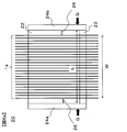
- FIG. 5 is a bottom view of the application unit 20 viewed from the direction of A in FIG.
- the coating unit 20 is provided with side wall members 24a, 24b for preventing the matrix resin 2 from leaking from both ends in the arrangement direction of the reinforcing fiber sheet 1a, and is surrounded by the wall members 21a, 21b and the side wall members 24a, 24b.
- An outlet 25 of the constricted portion 23 is formed in the closed space.
- the outlet 25 has a slit shape, and the sectional aspect ratio (Y / D in FIG. 3) may be set according to the shape of the reinforcing fiber sheet 1a to which the matrix resin 2 is to be applied.
- FIG. 6A is a cross-sectional view illustrating the structure inside the coating unit when the coating unit 20 is viewed from the direction B.
- the wall member 21b is omitted for easy viewing
- the reinforcing fiber sheet 1a depicts the reinforcing fibers 1 so as to be arranged with a gap therebetween. Arrangement without any gap is preferable from the viewpoint of the quality of the sheet prepreg and the mechanical properties of the FRP.
- FIG. 6 b shows the flow of the matrix resin 2 in the gap 26.
- a vortex flows in the matrix resin 2 in the direction of R. Since the vortex flow R becomes a flow (Ra) directed outward at the lower portion of the liquid pool 22, the reinforcing fiber sheet may be torn (breakage of the sheet-like fiber bundle occurs) or the spacing between the reinforcing fibers may be reduced. The reinforced fiber sheet prepreg may be spread, which may cause uneven arrangement of the reinforcing fibers.
- the reinforcing fiber sheet 1a is compressed in the width direction, and the end may be broken.
- Patent Literature 2 Japanese Patent No. 3252278
- the width of the gap 26 so as to suppress the generation of the vortex at the end.
- the width L of the liquid reservoir 22, that is, the interval L between the side plate members 24a and 24b may be configured to satisfy the following relationship with the width W of the reinforcing fiber sheet measured immediately below the narrowed portion 23. preferable. L ⁇ W + 10 (mm).
- the lower limit of L is not less than W-5 (mm) from the viewpoint of improving the uniformity of the dimension in the width direction of the prepreg 1b.
- the width regulation is performed at least at the lower part of the liquid reservoir 22 (the position G in FIG. 6A). Further, more preferably, when this width regulation is performed in the entire area of the liquid pool 22, the generation of the vortex flow R can be almost completely suppressed, and as a result, cracks and end breaks of the reinforcing fiber sheet can be almost completely prevented. Can be suppressed.
- the width regulation may be performed only on the liquid pool portion 22, but when the constriction portion 23 is similarly performed, the excess matrix resin 2 is applied to the side surface of the prepreg 1b. It is preferable from the viewpoint of suppressing this.
- the above-described coating step is basically the same as the first and second manufacturing methods. However, in the third manufacturing method, one or more bars are installed in the coating section. It is characterized by this that the impregnation proceeds. It is described in detail below.
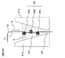
- the coating unit 20 by contacting the reinforcing fiber sheet 1a with a bar group 35 extending in the depth direction of the drawing inside the coating unit 20, air bubbles contained in the reinforcing fiber sheet 1a are squeezed out and discharged. Then, the matrix resin can be more efficiently impregnated inside the reinforcing fiber sheet 1a. Further, if necessary, the release sheet 3 can be applied to the prepreg 1c and wound up, as in the first and second manufacturing methods.
- the reinforcing fiber sheet 1a introduced into the liquid pool section 22 travels vertically downward Z while contacting the bars 35a, 35b, and 35c in this order inside the matrix resin 2.
- the reinforcing fiber sheet 1a is pressed against the bar, and the matrix resin 2 caught in the gap between the reinforcing fiber sheet 1a and the bar impregnates the inside of the reinforcing fiber sheet 1a and is contained inside the reinforcing fiber sheet 1a.
- the air bubbles are discharged to the outside of the reinforcing fiber sheet 1a from the surface opposite to the surface in contact with the bar so as to be squeezed out by the bar.
- the increased liquid pressure also has the effect of impregnating the inside of the reinforcing fiber sheet 1a with the matrix resin 2.
- This is based on the property (Darcy's law) that when a matrix material is impregnated into a porous body such as a reinforcing fiber bundle, the degree of impregnation increases with the pressure of the matrix resin. Even if the reinforcing fiber sheet 1a is insufficiently impregnated with the matrix resin 2 in the bar group 35, the matrix resin 2 is impregnated again in the lower part of the liquid reservoir 22, so that the prepreg 1b having a higher degree of impregnation is obtained. be able to. Also in this case, when the reinforcing fiber sheet 1a is run at a higher speed, the hydraulic pressure is further increased, so that the impregnation effect can be further enhanced.
- the reinforcing fiber sheet 1a is automatically centered at the center of the gap D by the increased liquid pressure, and the reinforcing fiber sheet 1a does not directly rub against the wall surface of the liquid reservoir 22 or the narrowed portion 23. It also has the effect of suppressing the generation of fluff. This is because when the reinforcing fiber sheet 1a approaches one of the gaps D due to disturbance or the like, the matrix resin 2 is pushed into the narrower gap on the approaching side and is compressed, so that the hydraulic pressure increases on the approaching side. Then, the reinforcing fiber sheet 1a is pushed back to the center of the gap D.
- the total amount of the matrix resin 2 applied to the reinforcing fiber sheet 1a can be controlled by the gap D of the narrowed portion 23.
- the wall members 21a and 21b may be installed so that the gap D is widened.
- the present invention is not limited to this. It is sufficient that the reinforcing fiber sheet 1a is substantially vertically downward as long as the reinforcing fiber sheet 1a can be stably and continuously driven. Further, when the reinforcing fiber sheet 1a is in contact with the bar group 35, the traveling direction of the reinforcing fiber sheet 1a changes, but the traveling direction of the reinforcing fiber sheet 1a is also substantially vertical as long as bubbles discharged from the reinforcing fiber sheet 1a do not accumulate around the bar group 35. It just needs to be downward.
- FIG. 7 shows an example in which the bar group 35 is composed of three bars 35a, 35b, and 35c in the application unit 40 in FIG. 7, but the present invention is not limited to this, and the number of bars may be one or more. Further, in the application section 40 of FIG. 7, all the bars are arranged so as to sink inside the matrix resin 2, but the present invention is not limited to this, and at least one or more bars are arranged so as to sink inside the matrix resin 2. It should just be. However, the greater the number of bars that come into contact with the reinforcing fiber sheet 1a inside the matrix resin 2, the higher the effect of the matrix resin impregnation becomes. Therefore, it is preferable to arrange a plurality of bars so as to sink inside the matrix resin 2. .
- FIG. 8 is a detailed cross-sectional view of the reinforcing fiber sheet 1a that contacts the bar 35 inside the matrix resin 2.
- FIG. The reinforcing fiber sheet 1a and the bar 35 are in contact at the holding angle ⁇ .
- the holding angle ⁇ is an angle formed by an arc connecting a point P1 at which the reinforcing fiber sheet 1a contacts the bar 35 and a point P2 at which the reinforcing fiber sheet 1a is separated from the bar 35 to a center point Pc of the bar 35.
- the possibility that the reinforcing fiber sheet 1a rubs against the bar 35 to generate fluff increases.
- the matrix resin 2 caught in the gap between the reinforcing fiber sheet 1a and the bar 35 is completely impregnated into the inside of the reinforcing fiber sheet 1a and depleted, the reinforcing fiber sheet 1a and the bar 35 directly rub against each other. The likelihood of occurrence increases rapidly.
- the holding angle ⁇ between the reinforcing fiber sheet 1a and the bar 35 is preferably set to 40 ° or less, and more preferably 20 ° or less.
- the holding angle ⁇ needs to be 10 ° or more.
- the cross-sectional shape of the bar 35 is circular, but the present invention is not limited to this, and the cross-sectional shape of the bar may be other than circular.
- a rectangular shape with rounded corners as shown in FIG. 9A or an elliptical shape as shown in FIG. 9B may be used.
- the surface that comes into contact with the reinforcing fiber sheet 1a has no sharp corners and has a smooth curve.
- the bar 35 does not need to be dense inside, and may be a hollow pipe, for example.
- the diameter (or representative length) of the cross section of the bar 35 is not particularly defined. However, as the diameter of the bar 35 increases, the length of contact between the reinforcing fiber sheet 1a and the bar 35 increases, and as described above, fluff may occur. It is preferable to reduce the diameter of the bar 35 to such an extent that the bar 35 is not deformed by the tension of the reinforcing fiber sheet 1a because the property is enhanced. Further, from the viewpoint of suppressing deformation of the bar 35, the material of the bar is preferably a highly rigid metal such as stainless steel.
- the surface of the bar 35 be finished smoothly. This is to make it difficult to generate fluff when the reinforcing fiber sheet 1a comes into contact with the bar 35.
- the matrix resin impregnation effect can be obtained by using a roll that rotates in the application section 40 as the bar 35.
- the matrix The bar 35 is preferably a non-rotating fixed member because a part of the reinforcing fiber sheet 1a may be wound around a roll due to the viscosity of the resin 2 and the reinforcing fiber sheet 1a may not be able to run.
- a guide roll (conveying roll) 13 is provided vertically above the application unit 40, and the reinforcing fiber sheet 1 a traveling in the horizontal direction is brought into contact with the guide roll 13 to move the traveling direction downward in the vertical direction. If the coating device 100 is guided after the change, the height of the coating device 100 in the vertical direction can be reduced, which is preferable from the viewpoint of reducing the construction cost of the building in which the coating device 100 is installed.
- the uppermost bar 35a of the bar group 35 is in contact with the reinforcing fiber sheet 1a on the surface opposite to the surface of the reinforcing fiber sheet 1a that is in contact with the guide roll 13. This is because the reinforcing fiber sheet 1a running on the guide roll 13 has a slight speed difference in the thickness direction due to the circumferential length difference, but the bar 35a has the reinforcing fiber sheet on the same side as the guide roll 13. This is because the above-mentioned speed difference further accumulates when contacting with 1a, and the reinforcing fiber sheet 1a becomes slack inside the application section 40.
- the width regulating mechanism 27a is provided between the side wall members 24a and 24b. 27b can be provided, and the width can be regulated by such a mechanism. This is preferable from the viewpoint that the width regulated by the width regulating mechanism can be freely changed, so that a matrix resin-impregnated reinforced fiber sheet having various widths can be manufactured by one application portion.
- the relationship between the width (W) of the matrix resin-impregnated reinforcing fiber sheet immediately below the constriction and the width (L2) regulated by the width regulating mechanism at the lower end of the width regulating mechanism is L2 ⁇ W + 10 (mm). Is more preferable, and L2 ⁇ W + 2 (mm) is more preferable. Further, the lower limit of L2 is adjusted to be not less than W-5 (mm), more preferably not less than W (mm), from the viewpoint of improving the uniformity of the dimension in the width direction of the matrix resin-impregnated reinforced fiber sheet prepreg 1b. Is preferred. There is no particular limitation on the shape and material of the width regulating mechanism, but a plate-shaped bush is simple and preferable.
- the width is smaller than the distance between the wall members 21a and 21b (see FIG. 10, which indicates the length in the vertical direction of the width regulating mechanism in the figure viewed from the Z direction). By having this, it is possible to prevent the matrix resin from flowing in the horizontal direction, which is preferable.
- the shape from the middle part to the lower part of the width regulating mechanism conforms to the internal shape of the application part, because the stagnation of the matrix resin in the liquid pool part can be suppressed and the deterioration of the matrix resin can be suppressed. In this sense, it is preferable that the width regulating mechanism is inserted up to the constriction 23.
- FIG. 10 shows an example of the plate-shaped bush 27 as the width regulating mechanism, but shows an example in which the lower part from the middle of the bush is inserted along the tapered shape of the liquid reservoir 22 to the constriction 23.
- FIG. 10 shows an example in which L2 is constant from the liquid level to the outlet, but the width regulated by the portion may be changed within a range that achieves the purpose of the width regulating mechanism.
- the width regulating mechanism can be fixed to the application section 20 by an arbitrary method. However, in the case of the plate-shaped bush 27, the plate-shaped bush 27 is deformed by high hydraulic pressure by fixing at a plurality of portions in the vertical direction. The fluctuation of the regulation width due to the above can be suppressed. For example, it is preferable to use a stay for the upper portion and to insert the lower portion into the application portion, since the width can be easily regulated by the width regulating mechanism.
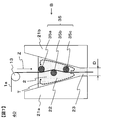
- FIG. 11 is a detailed cross-sectional view when the application unit 40 in FIG. 7 is viewed from the direction B.
- the wall member 21b is omitted.
- Each of the bar groups 35 in FIG. 11 has a columnar shape having a uniform cross section.
- the matrix resin 2 caught in the gap between the reinforcing fiber sheet 1a and the bar 35 causes the reinforcing fiber sheet 1a. Not only impregnate the inside, but also flow from both ends of the reinforcing fiber sheet 1a in the direction of E in FIG.
- the fibers at both ends of the reinforcing fiber sheet 1a are also moved in the direction of E in FIG. If the reinforced fiber sheet 1a spreads, the width of the reinforcing fiber sheet 1a changes, or the density of the fibers at both ends of the reinforcing fiber sheet 1a decreases, so that the prepreg 1b of uniform quality cannot be obtained. Also, when a reinforced fiber fabric is used as the reinforced fiber sheet 1a, both ends of the reinforced fiber fabric may be pulled by the flow of the matrix resin 2, and the width may be changed. In the worst case, both ends of the reinforcing fiber sheet 1a may fall off from the bar group 35, making it impossible to run.
- UD base material unidirectional material in which the reinforcing fibers 1 are arranged in one direction
- FIG. 12 is a detailed cross-sectional view of the application section 41 of the embodiment different from FIG. 12, a bar group 36 having a width regulating member at both ends is provided instead of the bar group 35 having a uniform cross section.
- the width regulating member a disk-shaped member having a large diameter may be provided at both ends of each bar as shown in FIG.
- a plurality of bars may be formed by two parallel plates as shown in FIG. It may be sandwiched. Further, as shown in FIG. 15, the side plate member 24 of the liquid reservoir may be brought into contact with the bar group 36, and the side plate member 24 may be used as a width regulating member.
- the width regulating member shown in FIG. 13 it is preferable that the diameter d2 of the disc-shaped members at both ends of the bar satisfy the relationship of d2 ⁇ d1 + 1 (mm). This is to prevent the reinforcing fiber sheet 1a from falling off from both ends of the bar.
- the thickness W3 of the disk-shaped member may be large enough to prevent the disk-shaped member from being deformed by being pushed by the reinforcing fiber sheet 1a. Specifically, W3 is preferably set to 1 mm or more.
- the interval W2 inside the width regulating member of the bar group 36 is preferably equal to or less than the width W1 of the slit-shaped outlet. This is because if the interval W2 inside the width regulating member of the bar group 36 is wider than the width W1 of the slit-shaped outlet, the reinforcing fiber sheet 1a widened in the bar group 36 passes through the narrow slit-shaped outlet. This is because both ends of the reinforcing fiber sheet 1a may be rubbed at the slit-shaped outlet and fuzz may be generated.
- the interval W2 inside the width regulating member of the bar group 36 is too narrow with respect to the width W1 of the slit-shaped outlet, the narrow reinforcing fiber sheet 1a passing through the bar group 36 will suddenly become wider at the slit-shaped outlet. Is spread, and the arrangement of the fibers may be disturbed at both ends of the reinforcing fiber sheet 1a.
- the difference between the interval W2 inside the width regulating member of the bar group 36 and the width W1 of the slit-shaped outlet exceeds 10 mm, the arrangement of the fibers may be disturbed at both ends of the reinforcing fiber sheet 1a.
- the liquid pressure is increased in the running direction of the reinforcing fiber sheet by continuously decreasing the cross-sectional area in the running direction of the reinforcing fiber sheet in the liquid reservoir 22. It is important to note that the continuous decrease in the cross-sectional area in the running direction of the reinforcing fiber sheet is not particularly limited as long as the hydraulic pressure can be continuously increased in the running direction.
- the liquid reservoir may have a curved shape such as a tapered shape (linear shape) or a trumpet shape.
- cross-sectional area decreasing portion may be continuous over the entire length of the liquid pool portion, or may include a portion where the cross-sectional area does not decrease or a portion which expands conversely as long as the object and effects of the present invention can be obtained. You may go out. These will be described in detail below with reference to FIGS. 16 to 19.
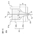
- FIG. 16 is a detailed cross-sectional view of the application section 20b of another embodiment different from FIG. It is the same as the coating unit 20 of FIG. 4 except that the shapes of the wall members 21c and 21d forming the liquid pool 22 are different.
- the liquid reservoir 22 may be divided into a region 22a in which the cross-sectional area continuously decreases in the vertical direction Z downward and a region 22b in which the cross-sectional area does not decrease.
- the vertical height H at which the cross-sectional area is continuously reduced is preferably 10 mm or more.
- the vertical height H at which the more preferable cross-sectional area is continuously reduced is 50 mm or more.
- the distance by which the matrix resin 2 entrained by the reinforcing fiber sheet 1a is compressed in the region 22a where the cross-sectional area of the liquid reservoir 22 is continuously reduced is secured, and the liquid generated in the lower portion of the liquid reservoir 22 is secured.
- the pressure can be increased sufficiently. As a result, it is possible to prevent the fluff from clogging the constricted portion 23 due to the liquid pressure, and to obtain the effect that the matrix resin 2 impregnates the reinforcing fiber sheet 1a with the liquid pressure.
- the opening angle ⁇ of the taper is smaller. More specifically, it is preferable to form an acute angle (90 ° or less). Thereby, the compression effect of the matrix resin 2 can be enhanced in the region 22a (tapered portion) where the cross-sectional area of the liquid reservoir 22 is continuously reduced, and a high liquid pressure can be easily obtained.
- FIG. 17 is a detailed cross-sectional view of the application unit 20c according to another embodiment different from FIG.
- the configuration is the same as the application unit 20b in FIG. 16 except that the wall members 21e and 21f forming the liquid reservoir 22 have a two-step tapered shape.
- the region 22a where the cross-sectional area of the liquid reservoir 22 is continuously reduced may be configured by a multi-stage taper portion of two or more stages. At this time, it is preferable to make the opening angle ⁇ of the tapered portion closest to the constricted portion 23 an acute angle from the viewpoint of enhancing the compression effect. Also in this case, it is preferable that the height H of the region 22a where the cross-sectional area of the liquid reservoir 22 is continuously reduced is 10 mm or more.
- the vertical height H at which the more preferable cross-sectional area is continuously reduced is 50 mm or more.
- the area 22 a where the cross-sectional area of the liquid reservoir 22 is continuously reduced is formed as a multi-stage tapered portion, so that the volume of the matrix resin 2 that can be stored in the liquid reservoir 22 is maintained while the constriction portion 23 is maintained. Can be further reduced. As a result, the liquid pressure generated in the lower portion of the liquid reservoir 22 is further increased, and the effect of removing fluff and the effect of impregnating the matrix resin 2 can be further enhanced.
- FIG. 18 is a detailed cross-sectional view of the application section 20d of another embodiment different from FIG.
- the configuration is the same as the application unit 20b in FIG. 16 except that the shape of the wall members 21g and 21h constituting the liquid reservoir 22 is stepped.
- the effect of increasing the hydraulic pressure which is the object of the present invention, can be obtained.
- the volume can be increased. As a result, even when the matrix resin 2 cannot be continuously supplied to the application section 20d, the matrix resin 2 can be continuously applied to the reinforcing fiber sheet 1a for a long time, and the productivity of the reinforcing fiber sheet prepreg 1b is further improved. .
- FIG. 19 is a detailed cross-sectional view of the application unit 20e of another embodiment different from FIG. It is the same as the application section 20b in FIG. 16 except that the shape of the wall members 21i and 21j constituting the liquid pool section 22 is a trumpet shape (curved shape).
- the region 22a where the cross-sectional area of the liquid reservoir 22 is continuously reduced is tapered (linear), but is not limited to this.
- a trumpet shape (curved shape) as shown in FIG. May be.
- the reinforcing fiber sheet 1a is caught by the step, and there is a concern that fluff is generated at this part.
- the region where the cross-sectional area of the liquid reservoir 22 is continuously reduced is a trumpet-like shape, the opening of the virtual tangent line at the lowermost part of the region 22a where the cross-sectional area of the liquid reservoir 22 is continuously reduced. It is preferable that the angle ⁇ be an acute angle.
- the cross-sectional area of the liquid reservoir does not necessarily have to be smoothly reduced unless the object of the present invention is impaired.
- FIG. 20 is a detailed cross-sectional view of the application unit 30 according to another embodiment different from the present invention.
- the liquid reservoir 32 in FIG. 20 does not include a region in which the cross-sectional area continuously decreases in the vertical direction Z, and the cross-sectional area is discontinuous and sharp at the boundary 33 with the constriction 23. It is a structure which reduces to. For this reason, the reinforcing fiber sheet 1a tends to be clogged at the narrowed portion.
- a traveling mechanism for transporting the reinforcing fiber sheet or the prepreg of the present invention As a traveling mechanism for transporting the reinforcing fiber sheet or the prepreg of the present invention, a known roller or the like can be suitably used. In the present invention, since the reinforcing fiber sheet is conveyed vertically downward, it is preferable to arrange rollers vertically above and below the application section.
- the running path of the reinforcing fiber sheet is as straight as possible in order to suppress the arrangement disorder and the fluffing of the reinforcing fiber.
- the sheet-like integrated material which is a laminate of the prepreg and the release sheet
- wrinkles may occur due to a difference in circumference between the inner layer and the outer layer.
- the path is as straight as possible. From this viewpoint, it is preferable to use a nip roll in the traveling path of the sheet-like integrated object.
- Whether the S-shaped roll or the nip roll is used can be appropriately selected according to the manufacturing conditions and the characteristics of the product.
- impregnation proceeds in the application section, and thereafter, additional impregnation can be performed to further advance the impregnation.
- the temperature of the matrix resin-impregnated reinforcing fiber sheet 1b immediately below the application section 20 is higher than room temperature. Therefore, if additional impregnation is performed immediately after leaving the application section, a heating device such as a hot plate for reheating the matrix resin-impregnated reinforced fiber sheet 1b without being cooled to room temperature can be omitted or simplified. .
- the prepreg 1c adjusted to a desired degree of impregnation can be obtained by providing the additional impregnating device 19 immediately below the application section and performing additional impregnation. For this reason, the distance N from the application section outlet to the additional impregnation start point is within 1 m. N is preferably 0.5 m or less.
- a non-contact heating device is disposed as a re-impregnation device, and re-impregnation by non-contact heating can be performed.
- the viscosity of the matrix resin contained in the matrix resin-impregnated reinforced fiber sheet 1b is increased by increasing the temperature, whereby the impregnation can be advanced by capillary action.
- P2 surface temperature of the matrix resin-impregnated reinforced fiber sheet at the end of heating
- M ° C.
- ⁇ P2 (° C.) is preferably M + 30 (° C.) or more, because impregnation is more likely to proceed.
- the distance from the application section outlet to the additional impregnation start point is a distance N2 from the application section exit to the heating start point by the non-contact heating device (see FIG. 26).
- a non-contact heating means infrared rays, far infrared rays, laser, heat medium (for example, steam or the like) can be used, but infrared rays are the most simple and preferable.
- the heating distance is not particularly limited as long as the temperature can be raised to the desired temperature up to the matrix resin-impregnated reinforced fiber sheet, but is preferably 1 m or less from the viewpoint of simplifying the apparatus.
- the heating distance is preferably 0.5 m or less.
- the pressing of the matrix resin-impregnated reinforced fiber sheet is not performed by using the non-contact heating device, the reinforced fiber layer may be disturbed by the surface tension of the matrix resin. For this reason, after performing additional impregnation by non-contact heating, it is also preferable to adjust the shape of the prepreg and the shape and arrangement of the reinforcing fiber layer by applying pressure.
- the pressing means a nip roll, an S-shaped roll, or the like is used. Can be.
- an apparatus provided with a pressurizing means can be used as the additional impregnation device.
- the distance N from the outlet of the application section to the pressure start point of the additional impregnation is 1 m or less, and the surface temperature P (° C.) of the matrix resin-impregnated reinforced fiber sheet before the additional impregnation is equal to the internal temperature of the application section.
- the temperature M (° C.) of the matrix resin stored inside the coating section 20 can be measured with a thermocouple.
- the surface temperature P (° C.) of the matrix resin-impregnated reinforced fiber sheet before additional impregnation can be measured with a radiation thermometer. Although the emissivity differs depending on the measurement object, the emissivity is assumed to be uniformly measured at 0.95.
- the measurement position of the surface temperature P (° C.) of the matrix resin-impregnated reinforcing fiber sheet 1 b is measured at a distance of 10 cm from the application start point of the additional impregnation to the application section 20.
- the matrix resin-impregnated reinforced fiber sheet 1b is located as close to the pressure start point as possible.
- the surface temperature P (° C.) is measured. Note that the measurement point is at the center in the width direction of the matrix resin-impregnated reinforced fiber sheet 1b.
- the measurement can be performed using an infrared radiation thermometer AD-5611A (manufactured by A & D Corporation, emissivity 0.95 fixed).
- the additional impregnation of the matrix resin-impregnated reinforced fiber sheet 1b immediately below the application section 20 is referred to as additional impregnation or additional impregnation in order to distinguish the impregnation at the application section.
- the obtained sheet is called prepreg 1c.
- the release sheet 3 by providing the release sheet 3, it is possible to prevent the matrix resin impregnated with the matrix resin of the roll or the device that comes into contact with the matrix resin-impregnated reinforcing fiber sheet 1b or the prepreg 1c during the manufacturing process. Since the running properties of the matrix resin-impregnated reinforced fiber sheet 1b and the prepreg 1c are improved, the release sheet 3 can be provided before the matrix resin-impregnated reinforced fiber sheet 1b is additionally impregnated.
- the release sheet 3 applied in the present invention is applied to the reinforcing fiber sheet 1a by heating the matrix resin 2 to a temperature higher than room temperature, before applying the release sheet 3 to the matrix resin-impregnated reinforcing fiber sheet 1b.
- the release sheet may be heated. Heating before applying the release sheet 3 is preferable because the surface temperature of the matrix resin-impregnated reinforced fiber sheet 1b with which it comes into contact can be significantly reduced and the impregnation degree can be suppressed.
- the heating device in the additional impregnation device can be omitted or simplified.
- the surface temperature T (° C.) of the release sheet before applying to the matrix resin-impregnated reinforced fiber sheet is too low than the surface temperature K (° C.) of the matrix resin-impregnated reinforced fiber sheet 1b before applying the release sheet, If the surface temperature T (° C.) of the release sheet before coming into contact with the matrix resin-impregnated reinforced fiber sheet is too high, the matrix resin-impregnated reinforced fiber sheet 1b will be removed from the matrix resin-impregnated reinforced fiber sheet 1b during additional impregnation. It protrudes and it becomes difficult to continue additional impregnation.
- the heating device for heating the release sheet 3 is not particularly limited, and various heating means such as air heating, infrared heating, far infrared heating, laser heating, contact heating, and heating medium heating (such as steam) can be used. Can be used.
- the surface temperature K (° C.) of the matrix resin-impregnated reinforced fiber sheet can be measured with a radiation thermometer. Although the emissivity differs depending on the measurement object, the emissivity is assumed to be uniformly measured at 0.95. As an example, the measurement can be performed using an infrared radiation thermometer AD-5611A (manufactured by A & D Corporation, emissivity 0.95 fixed).
- the surface temperature P (° C.) of the matrix resin-impregnated reinforced fiber sheet 1b before the additional impregnation cannot be directly measured when the release sheet 3 is provided, the surface temperature of the applied release sheet is measured and P ( ° C).
- the measurement position of P is measured at a distance of 10 cm from the starting point of the additional impregnation to the application section 20 side from the starting point.
- the measurement position of the surface temperature T (° C.) of the release sheet 3 is measured from a place where the release sheet 3 and the matrix resin-impregnated reinforced fiber sheet 1b are in contact with each other, at a distance of 10 cm to the release sheet supply device 18 side. I do. Note that the measurement point is the center of the release sheet 3 in the width direction.
- the measurement position of the surface temperature K (° C.) of the matrix resin-impregnated reinforced fiber sheet 1 b before applying the release sheet is measured at a position 10 cm away from the application section 20 starting from a place in contact with the release sheet 3. .
- the measurement is made at a place as close as possible to the place where the matrix resin-impregnated sheet and the release sheet come into contact. Note that the measurement point is at the center in the width direction of the matrix resin-impregnated reinforced fiber sheet 1b.
- the surface temperature P2 (° C.) of the matrix resin-impregnated reinforced fiber sheet at the thermal end point in the first production method can also be measured with a radiation thermometer.
- the measurement position is to measure the surface temperature of the prepreg 10 cm downstream from the non-contact heating device.
- the pressurizing method of the additional impregnation device 19 is not particularly limited.
- Preferable examples include a nip roll system that can reduce the roll diameter, set pressure, and contact length between the prepreg and the roll and can reduce the size of the device, and an S-shaped roll system that can obtain a take-up capability as well as impregnation by taking a large pressurized area.
- the pressing method is a nip roll
- the impregnation load obtained by dividing the force applied to the nip roll by the prepreg width is preferably 0.1 N / mm to 40 N / mm or less.
- the impregnation degree is too low, the impregnation degree is too low, and if it is too high, the matrix resin may protrude in the width direction, or the width of the prepreg may be excessively widened, so that a prepreg having a targeted basis weight may not be obtained.
- the roll When the matrix resin 2 is heated to a temperature higher than room temperature and applied to the reinforcing fiber sheet 1a, and a roll is used for pressurization during additional impregnation, the roll preferably has a heating mechanism. Thereby, a decrease in the surface temperature of the matrix resin-impregnated reinforced fiber sheet 1b can be suppressed, and high impregnation properties can be obtained.
- the additional impregnation device may have a heating device before pressurization. By heating the matrix resin-impregnated reinforced fiber sheet 1b before pressurization, the temperature of the matrix resin is increased, the viscosity of the matrix resin in the matrix resin-impregnated reinforced fiber sheet 1b is reduced, and high impregnation properties are obtained.
- the viscosity of the matrix resin in the matrix resin-impregnated reinforced fiber sheet 1b before the additional impregnation and pressurization may be low. Therefore, the viscosity of the matrix resin in the matrix resin-impregnated reinforced fiber sheet 1b before pressing is preferably 80 Pa ⁇ s or less when measured at a strain rate of 3.14 s ⁇ 1 . Since it is difficult to directly measure the viscosity of the matrix resin in the matrix resin-impregnated reinforced fiber sheet 1b before pressurization, the matrix resin-impregnated reinforced fiber sheet surface temperature P (° C.) before the additional impregnation described above is entered. , The matrix resin viscosity measured at a strain rate of 3.14 -1 is preferably 80 Pa ⁇ s or less.
- the additional impregnating device the following exemplified devices can be appropriately selected.
- a laminate of a sheet-like carbon fiber bundle and a resin is preheated by a hot plate to sufficiently soften the resin on the sheet-like carbon fiber bundle.
- the impregnation can also be advanced by using a device that presses with a heated nip roll.
- the temperature of the hot plate for preheating, the surface temperature of the nip roll, the linear pressure of the nip roll, and the diameter and number of the nip rolls can be appropriately selected so as to obtain a desired impregnation degree.
- FIG. 1 shows an example in which the prepreg sheet runs in an S-shape, but if impregnation is possible, the contact length between the sheet and the roll, such as a U-shape, V-shape or ⁇ -shape, is described. May be adjusted.
- the impregnation pressure is increased to increase the degree of impregnation, it is also possible to add an opposing contact roll. Further, as shown in FIG.
- the state of the impregnation of the matrix resin can be checked by checking the inside by tearing the collected prepreg and visually examining the inside, and more quantitatively evaluated by, for example, a peeling method. It is possible to The impregnation rate of the matrix resin by the peeling method can be measured as follows. That is, the collected prepreg is sandwiched between adhesive tapes, and the prepreg is peeled off to separate the reinforcing fibers to which the matrix resin has adhered from the reinforcing fibers to which the matrix resin has not adhered.
- the ratio of the mass of the reinforcing fibers to which the matrix resin has adhered to the mass of the entire reinforcing fiber sheet put in can be taken as the impregnation rate of the matrix resin by the peeling method.
- the impregnation degree by the peeling method is 80% or more, it is preferable from the viewpoint of handling of the prepreg.
- a high tension take-up device for drawing out the prepreg from the application section downstream of the application section. This is because high frictional force and shear stress are generated between the reinforcing fiber sheet and the matrix resin in the application section, and it is preferable to generate a high take-up tension downstream of the process in order to overcome the drawback and draw out the prepreg. It is.
- a nip roll or an S-shaped roll can be used, but by increasing the frictional force between the roll and the prepreg, slip can be prevented and stable running can be achieved. .
- the S-shaped roll is preferable because the frictional force can be easily controlled by the roll diameter and the contact length.
- a release sheet feeding device or a winder can be used as appropriate, and as such a device, a known device can be used. It is preferable to provide a mechanism capable of feeding back the winding tension or feeding back the winding speed from the viewpoint of stable running of the sheet.
- the prepreg which is a kind of the precursor of FRP, is one form of the reinforcing fiber sheet obtained in the present invention
- the case where the present invention is applied to the FRP application will be described below by referring to the reinforcing fiber sheet as a prepreg.
- the width of the prepreg is not particularly limited, and may be a wide width of about several tens cm to 2 m, or a tape having a width of several mm to several tens mm.
- the width can be selected according to the application.
- devices called ATL (Automated Tape Laying) and AFP (Automated Fiber Placement) for automatically laminating narrow prepregs and prepreg tapes have been widely used. Therefore, it is also preferable that the width is adjusted to this.
- ATL often uses narrow prepregs having a width of about 7.5 cm, about 15 cm, or about 30 cm.
- AFP often uses prepreg tapes having a width of about 3 mm to about 25 mm.
- the width of the coating portion used in the present invention can be adjusted so as to have a desired width from the beginning. For example, when manufacturing a narrow prepreg having a width of 30 cm for ATL, the width of the application section outlet may be adjusted accordingly. In addition, in order to manufacture this efficiently, it is preferable to manufacture the product with a product width of 30 cm. When a plurality of such manufacturing devices are arranged in parallel, the same traveling device / transport device, various rolls, and a winder are used. The prepreg of the line can be manufactured.
- a reinforcing fiber sheet in the form of a tape-shaped reinforcing fiber bundle having a length of about 1 to 3 threads is formed and passed through a coating section whose width has been adjusted so as to obtain a desired tape width. You can also get it.
- the accuracy of the tape width is often required from the viewpoint of controlling the lateral overlap between the tapes. For this reason, it is preferable to more strictly control the outlet width of the application section.
- the above L, L2, and W satisfy the relationship of L ⁇ W + 1 mm and / or L2 ⁇ W + 1 mm. .
- the method of slitting the prepreg is not particularly limited, and a known slit device can be used. After winding the prepreg once, it may be installed in the slit device again to perform slitting, or for efficiency, a slitting step may be arranged continuously from the prepreg producing step without winding the prepreg once. Also, in the slitting step, a wide prepreg of 1 m or more may be directly slit to a desired width, or once cut and divided into narrow prepregs of about 30 cm, and then slit again to a desired width. good.
- a release sheet may be supplied independently, or one wide release sheet may be supplied.
- a plurality of prepregs may be stacked.
- the end in the width direction of the prepreg thus obtained can be cut off and supplied to an ATL or AFP device.
- the matrix resin component resin in the case of CFRP
- adhering to the slit cutter blade can be reduced, and the cleaning cycle of the slit cutter blade is extended. There is also an advantage that you can do it.
- the matrix resin is stored in the coating section, but it is preferable to appropriately supply the matrix resin because the coating proceeds.
- the mechanism for supplying the matrix resin to the application section is not particularly limited, and a known device can be used. It is preferable that the matrix resin be continuously supplied to the application section because the running of the reinforcing fiber sheet can be stabilized without disturbing the liquid level above the application section.
- the self-weight can be supplied as a driving force from a tank storing the matrix resin, or can be supplied continuously using a pump or the like.
- a pump, a gear pump, a tube pump, a pressure pump, or the like can be used as appropriate according to the properties of the matrix resin.
- the matrix resin When the matrix resin is solid at room temperature, it is preferable to provide a melter above the reservoir. Further, a continuous extruder or the like can be used. Further, it is preferable to provide a mechanism capable of continuously supplying the matrix resin in accordance with the applied amount so that the liquid level above the application portion of the matrix resin is as constant as possible. For this purpose, for example, a mechanism that monitors the liquid level, the weight of the application section, and the like and feeds it back to the supply device is conceivable.
- the online monitoring method is not particularly limited, and a known method can be used.
- a device for measuring the thickness for example, a beta-ray meter or the like can be used.
- the application amount monitored online is immediately fed back to the application unit, and can be used for adjusting the temperature of the application unit and the gap D (see FIG. 2) of the constricted portion 23.
- Application amount monitoring can of course be used as defect monitoring.
- As the thickness measurement position for example, in FIG.
- the thickness of the reinforcing fiber sheet 416 can be measured near the direction change roll 419, and the thickness of the prepreg can be measured near the high tension take-up device 444. It is also preferable to perform online defect monitoring using infrared rays, near infrared rays, a camera (image analysis), or the like.
- the prepreg manufacturing apparatus of the present invention includes a traveling mechanism for running the reinforcing fiber sheet substantially vertically downward, an application mechanism for applying a matrix resin to the reinforcing fiber sheet to obtain a matrix resin-impregnated reinforced fiber sheet, and a matrix resin impregnation.
- a re-impregnation mechanism that presses the reinforcing fiber sheet at least, and a release sheet supply that supplies a release sheet to apply a release sheet to at least one surface of the matrix resin-impregnated sheet before performing additional re-impregnation on the matrix resin-impregnated sheet
- a prepreg manufacturing apparatus having a mechanism and a heating mechanism for heating a release sheet, wherein the coating mechanism is capable of storing a coating liquid therein, and further includes a liquid reservoir and a constricted part that are communicated with each other.
- the liquid reservoir has a portion whose cross-sectional area continuously decreases along the running direction of the sheet-like reinforcing fiber bundle,
- the constricted portion has a slit-shaped cross-section, and has a cross-sectional area smaller than the upper surface of the liquid reservoir, and the additional impregnation mechanism is arranged such that the pressure start point of the additional impregnation is within 1 m from the application mechanism,
- This is a prepreg manufacturing apparatus having a release sheet heating mechanism between a release sheet supply mechanism and an impregnation mechanism.
- FIG. 21 is a schematic view showing an example of a manufacturing process / apparatus of the first manufacturing method of the present invention.
- the plurality of reinforcing fiber bobbins 412 are hung on creels 411. Then, the reinforcing fiber bundle 414 can be pulled out with a constant tension by the brake mechanism provided to the creel.
- the plurality of pulled out reinforcing fiber bundles 414 are orderly arranged by the reinforcing fiber arrangement device 415, and the reinforcing fiber sheet 416 is formed.
- FIG. 21 only three yarns are drawn on the reinforcing fiber bundle, but in practice, it can be one yarn to several hundred yarns, and can be adjusted to have a desired prepreg width and fiber weight. is there.
- the sheet is conveyed via a widening device 417 and a smoothing device 418, and a direction change roll 419.
- the reinforcing fiber sheet 416 is linearly conveyed between the reinforcing fiber arrangement device 415 and the direction change roll 419 between the devices.
- the widening device 417 and the smoothing device 418 can be appropriately skipped or the devices can be omitted depending on the purpose.
- the arrangement order of the reinforcing fiber arrangement device 415, the widening device 417, and the smoothing device 418 can be appropriately changed according to the purpose.
- the reinforcing fiber sheet 416 travels vertically downward from the direction changing roll 419, passes through the reinforcing fiber preheating device 420, and the application section 430, and the matrix resin impregnated reinforcing fiber sheet 421 is obtained. Then, the trix resin-impregnated reinforced fiber sheet 421 is passed through a non-contact heating device 423 installed at a distance N immediately below the application section 430 to advance impregnation. Further, a release sheet is provided on the direction change roll 445, and the sheet-like integrated body is cooled by the cooling device 461, is taken up by the take-up device 462, peels off the upper release sheet 446, and is then taken up by the winder 464.
- FIG. 22 is a schematic view showing an example of a manufacturing process / apparatus of the second manufacturing method of the present invention.
- the plurality of reinforcing fiber bobbins 412 are hung on a creel 411, and are pulled out upward through a direction changing guide 413. At this time, the reinforcing fiber bundle 414 can be pulled out with a constant tension by the brake mechanism provided to the creel.
- the plurality of pulled out reinforcing fiber bundles 414 are orderly arranged by the reinforcing fiber arrangement device 415, and the reinforcing fiber sheet 416 is formed.
- the sheet is conveyed vertically downward through a widening device 417, a smoothing device 418, and a direction change roll 419.
- the reinforcing fiber sheet 416 is linearly conveyed between the reinforcing fiber arrangement device 415 and the direction change roll 419 between the devices.
- the widening device 417 and the smoothing device 418 can be appropriately skipped or the devices can be omitted depending on the purpose.
- the arrangement order of the reinforcing fiber arrangement device 415, the widening device 417, and the smoothing device 418 can be appropriately changed according to the purpose.
- the reinforcing fiber sheet 416 travels vertically downward from the direction changing roll 419, passes through the reinforcing fiber preheating device 420, and the application section 430, and the matrix resin impregnated reinforcing fiber sheet 421 is obtained.
- the coated matrix resin-impregnated reinforced fiber sheet 421 is unwound from the release sheet supply device 442, the release sheet 446 is applied to both sides, and reaches the high tension take-up device 444 via the additional impregnation device 440.
- the release sheet 446 is provided from both sides, but may not be provided, or may be provided on only one side.
- the release sheet 446 may be heated by the release sheet heating device 422.
- the application section 430 can adopt any application section shape as long as the object of the present invention is achieved. For example, there are shapes as shown in FIG. 4, and FIGS. Further, a bush 27 can be provided as shown in FIG. Further, as shown in FIG. 7, a bar can be provided in the application section.
- the additional impregnating device can employ any device configuration as long as the object of the present invention is achieved.
- an additional impregnation device including a heating nip roll 452 is illustrated as the additional impregnation device 440.
- the prepreg / release sheet (sheet-like integrated material) 472 having a high degree of impregnation can be obtained by passing through the additional impregnation device.
- the heating nip roll 452 is drawn as an example of the pressing method, but a small heating S-shaped roll may be used depending on the purpose.
- the sheet-like integrated body is cooled by the cooling device 461, is taken by the take-up device 462, peels off the upper release sheet 446, and is wound up by the winder 464 to be a prepreg / release sheet to be a product.
- a sheet-like integrated body 472 can be obtained.
- the drawing of the matrix resin supply device and the online monitoring device is omitted.
- FIG. 23 is a schematic view of another example of a prepreg manufacturing process / apparatus using the second manufacturing method.
- the reinforcing fiber bundle 414 is pulled out from the creel 411, the reinforcing fiber sheet 416 is formed as it is by the reinforcing fiber arranging device 415, and then is linearly conveyed to the widening device 417 and the smoothing device 418. 23 in that the sheet 416 is guided upward.
- FIG. 24 is a schematic view of another example of a prepreg manufacturing process / apparatus using the present invention.
- a creel 411 is installed on the floor, and the traveling path of the reinforcing fiber sheet 416 is further linearized.
- FIG. 25 is a schematic view of another example of a prepreg manufacturing process / apparatus using the present invention.
- an example is shown in which the heated S-shaped roll 455 is also used as a high tension take-up device.
- the entire prepreg manufacturing apparatus can be made very compact.
- the arrangement of the contact rolls 456 is illustrated to increase the degree of impregnation, the arrangement is not necessary.
- first, second, and third manufacturing methods of the present invention can be used in an appropriate combination.
- Examples 1 to 3 correspond to the first manufacturing method
- Examples 4 to 5 correspond to the second manufacturing method
- Examples 6 to 15 correspond to the third manufacturing method.
- Prepreg manufacturing equipment As the prepreg manufacturing apparatus, an apparatus having a configuration shown in FIG. 26 for the first manufacturing method, an apparatus shown in FIG. 22 for the second manufacturing method, and an apparatus shown in FIG. Note that a widening device, a smoothing device, and a cooling device were not used.
- a coating section of a coating section 20c type shown in FIG. 17 is used as the coating section, and the coating section is made of stainless steel.
- a ribbon heater was wound around the outer periphery, and the temperature and viscosity of the matrix resin could be adjusted while measuring the temperature with a thermocouple.
- the running direction of the reinforcing fiber sheet in the liquid reservoir is vertically downward, and the liquid reservoir has a two-stage tapered shape.
- the first-stage taper has an opening angle of 17 ° and a taper height (ie, H) of 100 mm.
- the opening angle of the second-stage taper was 7 °.
- a plate-shaped bush 27 adapted to the inner shape of the application portion as shown in FIG. 10 was provided, L2 was set to 20 mm, and the gap D of the constricted portion was set to 0.2 mm.
- the outside of the stenosis portion was closed off from the bush so that the matrix resin did not leak from the stenosis portion exit.
- the liquid reservoir 22 is a tapered flow path whose cross-sectional area continuously decreases.
- the height H of the liquid reservoir 22 is 100 mm
- the opening angle ⁇ of the tapered portion is 30 °
- the gap D of the constricted portion 23 is 0. 0.2 mm (slit shape, aspect ratio 100).
- Stainless steel blocks were used for the wall members 21a and 21b forming the liquid reservoir 22 and the constricted portion 23.
- a stainless steel plate was used for the side plate member 24.
- a ribbon heater was wound around the wall member 21 and the side plate member 24, and the temperature of the epoxy resin as the matrix resin was adjusted to 90 ° C. while measuring the temperature with a thermocouple.
- Release paper having a width of 100 mm was used as the release sheet.
- the release sheet heating device was used in Example 5 and Comparative Example 5.
- a heat gun was used as a heating device for the release sheet. The heat gun was placed at a position 30 cm from the place where the matrix resin-impregnated reinforcing fiber sheet and the release sheet were in contact with the release sheet supply device side to heat the release sheet. The distance at which the heat gun is applied to the release sheet is adjusted, and the temperature at the center of the release sheet in the width direction is 90 ° C. at a position 10 cm away from the place where the matrix resin impregnated reinforced fiber sheet and the release sheet come into contact with each other. It was made to become. The location of the release sheet in contact with the matrix resin-impregnated reinforced fiber sheet was 30 cm from the outlet of the application section on the side of the high tension take-up device.
- ⁇ Addition impregnation device> In the first manufacturing method, a non-contact heating device using an infrared heater was used. The length of the heating section was 0.5 m.
- the nip roll near the coating unit side is installed so that the distance N from the coating unit outlet to the pressure start point of the additional impregnating device is 0.5 m, and the nip roll near the high tension take-up device side is near the coating unit side.
- the nip roll was set so that the distance between the nip roll and the pressure start point was 100 mm.
- the diameter of the nip roll was 50 mm.
- the nip force of the nip roll during pressurization was 400 N.
- Matrix resin A thermosetting epoxy resin composition
- It is a mixture of an epoxy resin (a mixture of an aromatic amine type epoxy resin and a bisphenol type epoxy resin), a curing agent (diaminodiphenyl sulfone), and a polyether sulfone.
- the viscosity of this thermosetting epoxy resin 1 was measured using ARES-G2 manufactured by TA Instruments at a measurement frequency of 0.5 Hz and a heating rate of 1.5 ° C./min.
- 80 ° C. 80 Pa ⁇ s at 70 ° C., 51 Pa ⁇ s at 75 ° C., and 15 Pa ⁇ s at 90 ° C.
- the degree of impregnation was 90% or more of Excellent, 70% or more and less than 90% Good, and less than 70% Bad.
- the temperature at the center of the matrix resin-impregnated reinforced fiber sheet was measured 10 cm downstream of the non-contact heating device.
- the surface temperature P (° C.) of the matrix resin-impregnated reinforced fiber sheet before the additional impregnation in Example 4 and Comparative Example 6 of the second production method is a distance of 10 cm from the starting point of pressing the nip roll near the application section to the application section.
- the surface temperature at the center in the width direction at the location was measured.
- the surface temperature P (° C.) of the matrix resin-impregnated reinforced fiber sheet before the additional impregnation in Example 5, Comparative Example 2, and Comparative Example 5 is a pressure starting point of the nip roll near the application section side because the release sheet is provided.
- the surface temperature of the release sheet at the center in the width direction at a distance of 10 cm to the application portion side was measured as P. Furthermore, the surface temperature T (° C.) of the release sheet before contacting the matrix resin-impregnated reinforced fiber sheet of Example 5, Comparative Example 4, or Comparative Example 5 using the release sheet is determined by the release sheet and the matrix resin-impregnated reinforced fiber. The surface temperature at the central portion in the width direction at a point at a distance of 10 cm from the place where the sheet was in contact with the release sheet feeding device side was measured.
- the surface temperature K (° C.) of the matrix resin-impregnated reinforced fiber sheet before applying the release sheet is determined at the center in the width direction at a distance of 10 cm from the place where the release sheet and the matrix resin-impregnated sheet come in contact with the application section side. The surface temperature was measured.
- the running speed of the reinforcing fiber sheet and the prepreg was 10 m / min.
- the impregnation degree of the obtained prepreg was evaluated, it was Good at 92%.
- the cross section of the composite after lamination and curing was observed, no disturbance of the carbon fiber layer was observed, and the prepreg quality was good.
- Comparative Example 3 An experiment was conducted in the same manner as in Comparative Example 2 except that the distance N2 from the outlet of the coating section to the non-contact heating device was 1.3 m, and the running speed of the prepreg was 0.5 m / min. Although it was possible to raise the temperature to 90 ° C., when the composite cross section after lamination and curing was observed, the carbon fiber layer was disturbed, and the prepreg quality was poor.
- Example 4 A reinforcing fiber is drawn out from a reinforcing fiber bobbin hung on a creel, three reinforcing fiber yarns are arranged in a width direction by a reinforcing fiber arrangement device, a reinforcing fiber sheet is formed, and a matrix resin A heated to 90 ° C. was led to a coating section for storing, and the matrix resin A was coated. Thereafter, the matrix resin-impregnated reinforced fiber sheet was pulled out from the application section, installed so that the distance N from the application section exit to the pressure start point of the additional impregnation device was 0.5 m, and two heating nip rolls set at 100 ° C.
- a prepreg was obtained by passing a matrix resin-impregnated reinforced fiber sheet through an additional impregnation device, and was wound up with a winder.
- the running speed of the reinforcing fiber sheet and the prepreg was set to 20 m / min.
- the degree of impregnation of the obtained prepreg was evaluated, it was good at 80% or more.
- the surface temperature P of the matrix resin-impregnated reinforced fiber sheet before entering the additional impregnation device was 70 ° C.
- Example 5 The release paper was peeled off using a release sheet (upper) winding device 463 in the same manner as in Example 4 except that a release sheet heated to a surface temperature of 90 ° C. was provided before entering the additional impregnation device. A sheet-like monolith was obtained. When the degree of impregnation of the obtained prepreg was evaluated, it was good at 80% or more.
- the surface temperature P of the matrix resin impregnated reinforced fiber sheet before entering the re-impregnation device measured from above the release sheet is 75 ° C.
- the surface temperature T of the release sheet is 90 ° C.
- the matrix resin before the release sheet is applied.
- the surface temperature K of the impregnated reinforcing fiber sheet was 80 ° C.
- the prepregs obtained in Examples 4 and 5 were slit to obtain a prepreg tape having a width of 7 mm. Since the impregnation of these prepreg tapes was sufficiently advanced, the adhesion of the resin to the cutter blade of the slitter was small.
- Example 5 A matrix resin reinforced fiber sheet was obtained in the same manner as in Example 5, except that pressure was not applied by a nip roll. When the impregnation degree of the obtained matrix resin impregnated reinforced fiber sheet was evaluated, it was less than 70% and Bad.
- a prepreg was prepared in the same manner as in Example 4, except that the additional impregnating device was installed so that the distance N from the outlet of the coating section to the pressure start point of additional impregnation was 1.5 m.
- the impregnation degree of the obtained prepreg was evaluated, it was less than 70% and Bad.
- the surface temperature P of the matrix resin-impregnated reinforced fiber sheet before the additional impregnation was 50 ° C.
- Example 6 A molten epoxy resin was applied to a carbon fiber sheet using the application unit 20 of the embodiment of FIG. 7 according to the present invention.
- the bar group 35 three stainless steel polishing rods having a diameter of 10 mm and a length of 40 mm were used.
- the holding angles of the carbon fiber sheet and the bars 35a, 35b, 35c are 10 °, 20 °, 10 °, respectively, and all the bars are submerged in the matrix resin 2.
- the bar 35a located at the uppermost stage is in contact with the carbon fiber sheet on the surface opposite to the surface of the carbon fiber sheet that is in contact with the guide roll 13.
- the bar group 35 has a uniform cross section in the length direction as shown in FIG. 11, and does not include a width regulating member.
- the width W1 of the slit-shaped outlet was 20 mm.
- the degree of impregnation of the obtained prepreg was quantitatively evaluated by a peeling method.
- the impregnation degree of the coating liquid by the peeling method can be measured as follows. That is, the collected coating liquid impregnated reinforcing fiber sheet is sandwiched between adhesive tapes, and is separated to separate the reinforcing fiber to which the coating liquid has adhered and the reinforcing fiber to which the coating liquid has not adhered. Then, the ratio of the mass of the reinforcing fibers to which the coating liquid has adhered to the mass of the whole reinforcing fiber sheet put therein can be taken as the impregnation degree of the coating liquid by the peeling method.
- the impregnation degree of the prepreg obtained in Example 7 was 73%.
- Example 7 a molten epoxy resin was applied to the carbon fiber sheet using the application unit 43 of the embodiment of FIG. 27 according to the present invention.
- the bar 35 uses only one postal bar having a diameter of 10 mm and a length of 40 mm.
- the holding angle between the carbon fiber sheet and the bar 35 was 20 °.
- the bar 35 is submerged in the coating liquid 2.
- the impregnation degree of the obtained sheet prepreg was measured by a peeling method, the impregnation degree was 60%. Although the absolute value of the impregnation degree is low, the effect of the bar is recognized from the comparison with Comparative Example 7.
- Table 4 is a table summarizing the experimental results of producing a sheet-shaped prepreg by applying a molten epoxy resin to a carbon fiber sheet using the application section 41 of the embodiment of FIG. 12 according to the present invention.
- the traveling speed of the carbon fiber sheet was 20 m / min. Details will be described below.
- Example 8 A molten epoxy resin was applied to the carbon fiber sheet using the application section 41 according to the present invention shown in FIG.
- the bar group 36 As the bar group 36, as shown in FIG. 13, a stainless steel bar having a disk-shaped width regulating member with a large diameter at both ends was used.
- the diameter d1 of the bar group 36 is 10 mm
- the diameter d2 of the width regulating member is 14 mm
- the interval W2 inside the width regulating member is 20 mm
- the thickness W3 of the width regulating member is 2 mm.
- An integrated material was used.
- the arrangement of the bar group 36 is the same as that of the application unit 40 (Example 7) in the embodiment of FIG.
- the holding angle between the carbon fiber sheet and the bars 36a, 36b, and 36c is 10 °, 20 °, and 10 °, respectively. is there.
- the impregnation degree of the obtained sheet prepreg was measured by a peeling method.
- the prepreg was visually checked, and one in which the carbon fibers were arranged with a uniform thickness and no gap over the entire width (20 mm) was referred to as “Excellent”.
- Example 9 Next, the width W1 of the slit-shaped outlet in Example 8 was changed to 30 mm, and a molten epoxy resin was applied to the carbon fiber sheet. This embodiment also satisfies the relationship of 0 ⁇ W1 ⁇ W2 ⁇ 10. The degree of impregnation of the prepreg obtained in Example 9 was 71%, and the thickness was not uniform (the surface had irregularities), but the carbon fibers were present without gaps over the entire width (quality "Good”).
- Example 10 Next, the width W1 of the slit outlet in Example 8 was changed to 40 mm, and a molten epoxy resin was applied to the carbon fiber sheet. This embodiment does not satisfy the relationship of 0 ⁇ W1 ⁇ W2 ⁇ 10.
- the impregnation degree of the sheet-shaped prepreg obtained in Example 10 was 72%, there was a gap between some carbon fibers, and only the epoxy resin was continuously present in the running direction (quality “Fair”). ).
- Table 5 is a table summarizing the experimental results of producing a prepreg by applying a molten epoxy resin to a carbon fiber sheet using the application section 41 of the embodiment of FIG. 12 according to the present invention.
- the traveling speed of the carbon fiber sheet is 20 m / min, and a bar provided with a width regulating member having the same shape as that of the eighth embodiment is used for the bar group 36. Is 20 mm, which satisfies the relationship of 0 ⁇ W1 ⁇ W2 ⁇ 10. Details will be described below.
- Example 11 A molten epoxy resin was applied to the carbon fiber sheet by adjusting the position of the bar group 36 so that the holding angle of the carbon fiber sheet and the bars 36a, 36b, and 36c was 20 °, 40 °, and 20 °, respectively. During traveling, it was confirmed that the carbon fiber sheet occasionally turned around near the upper liquid level of the liquid reservoir 22. When the impregnation degree of the obtained prepreg was measured by a peeling method, the impregnation degree was 82%. When the quality of the obtained sheet-shaped prepreg was confirmed by visual inspection, the carbon fiber was present without gaps throughout the entire width (quality "Good"), although the thickness was partly not uniform (the surface had irregularities).
- Example 12 Next, a molten epoxy resin was applied to the carbon fiber sheet by adjusting the position of the bar group 36 so that the holding angles of the carbon fiber sheet and the bars 36a, 36b, and 36c were 40 °, 80 °, and 40 °, respectively. During the running, it was confirmed that the carbon fiber sheet was largely displaced near the upper liquid level of the liquid reservoir 22. When the impregnation degree of the obtained prepreg was measured by a peeling method, the impregnation degree was 90% or more.
- Example 13 The diameter d1 of the bar group 36 was changed to 20 mm, and a molten epoxy resin was applied to the carbon fiber sheet.
- the diameter d2 of the width regulating member was 24 mm.
- the position of the bar group 36 was adjusted so that the holding angles of the carbon fiber sheet and the bars 36a, 36b, and 36c were 10 °, 20 °, and 10 °, respectively.
- the impregnation degree of the obtained prepreg was measured by a peeling method, the impregnation degree was 84%.
- the quality of the obtained sheet-shaped prepreg was confirmed by visual inspection, the carbon fiber was present without gaps throughout the entire width (quality "Good"), although the thickness was partly not uniform (the surface had irregularities).
- Example 14 Next, a molten epoxy resin was applied to the carbon fiber sheet using the application section 44 of FIG. 28 according to the present invention.
- the traveling speed of the carbon fiber sheet was 20 m / min.
- This embodiment is the same as the embodiment 8 except that the surface where the bar group 36 contacts the carbon fiber sheet is opposite to that of the embodiment 8.
- the uppermost bar 36a is in contact with the carbon fiber sheet on the same surface as the surface of the carbon fiber sheet that is in contact with the guide roll 13.
- the carbon fiber sheet 1a occasionally turned around near the upper liquid level of the liquid reservoir 22.
- the impregnation degree of the obtained sheet prepreg was measured by a peeling method, the impregnation degree was 70%.
- the quality of the obtained sheet-shaped prepreg was confirmed by visual inspection, the carbon fiber was present without gaps throughout the entire width (quality "Good"), although the thickness was partly not uniform (the surface had irregularities).
- Example 15 A molten epoxy resin was applied to a carbon fiber sheet using the application section 41 of the embodiment of FIG. 12 according to the present invention. Except that the traveling speed of the carbon fiber sheet was set at 5 m / min, the conditions were the same as those in Example 9.
- the prepreg was visually checked to evaluate the quality of the obtained prepreg, and the carbon fibers were arranged with a uniform thickness and no gap over the entire width (20 mm). "Excellent” means that the thickness is not uniform (the surface has irregularities), but “Good” means that the carbon fibers are present without gaps over the entire width. Those having a portion or having a fluffy surface were designated as “Fair”.
- the impregnation degree of the sheet-shaped prepreg obtained in Example 9 was 90% or more, and the carbon fibers were arranged with a uniform thickness and no gap over the entire width (quality “Excellent”).
- the prepreg obtained by the production method of the present invention is a FRP typified by CFRP, and is a structural material or interior material for aerospace applications, automobiles, trains, ships, etc., a pressure vessel, an industrial material application, a sports material application, a medical device. It can be widely used for applications, housing applications, civil engineering and construction applications.
Abstract
Regarding a method for producing a prepreg that is obtained by applying a matrix resin to a fiber reinforced sheet, the present invention addresses the problem of providing a prepreg production method by which continuously travel can be performed without involving jamming of a generated fluff even when the travel speed is high, and by which a fiber reinforced sheet can be efficiently impregnated with a matrix resin. The present invention uses a prepreg production method comprising causing a fiber reinforced sheet to substantially, vertically downward pass through the inside of a coating part in which a matrix resin is reserved, so as to obtain a matrix resin-impregnated fiber reinforced sheet in which the matrix resin has been applied to the fiber reinforced sheet, and subsequently, heating at least the matrix resin-impregnated fiber reinforced sheet, wherein: the coating part is provided with a liquid reservoir section and a constriction section which are connected to each other; the liquid reservoir section has a portion the cross-sectional area of which continuously decreases along the travel direction of the fiber reinforced sheet; the constriction section has a slit-shaped cross section, and has a cross-sectional area smaller than that of the upper surface of the liquid reservoir section; the distance N from an outlet of the coating part to a heating start point of the matrix resin-impregnated fiber reinforced sheet is 1 m or shorter; and, at a heating end point, a surface temperature P2 (°C) of the matrix resin-impregnated fiber reinforced sheet is equal to or higher than the temperature M (°C) of the matrix resin reserved in the coating part (expression 1).
Description
本発明は、プリプレグ、プリプレグテープおよび繊維強化複合材料の製造方法、プリプレグ製造装置に関し、特に強化繊維シートにマトリックス樹脂を均一に含浸する方法、および装置に関する。
The present invention relates to a method for producing a prepreg, a prepreg tape and a fiber-reinforced composite material, and a prepreg production apparatus, and more particularly to a method and an apparatus for uniformly impregnating a reinforcing fiber sheet with a matrix resin.
熱可塑性樹脂や熱硬化性樹脂を含むマトリックス樹脂を強化繊維で補強した繊維強化複合材料(FRP)は、航空・宇宙用材料、自動車材料、産業用材料、圧力容器、建築材料、筐体、医療用途、スポーツ用途など様々な分野で用いられている。特に高い力学特性と軽量性が必要な場合には、炭素繊維強化複合材料(CFRP)が幅広く好適に用いられている。一方、力学特性や軽量性よりもコストが優先される場合にはガラス繊維強化複合材料(GFRP)が用いられる場合がある。FRPは強化繊維束にマトリックス樹脂を含浸し中間基材を得、これを積層、成形し、さらに熱硬化樹脂を用いた場合には熱硬化させて、FRPからなる部材を製造している。前記用途では平面状物やそれを折り曲げた形態のものが多く、FRPの中間基材としても1次元のストランドやロービング状物よりも、2次元のシート状物の方が部材を作製する際の積層効率や成形性の観点から幅広く使用されている。
Fiber reinforced composite material (FRP), which is a matrix resin containing thermoplastic resin and thermosetting resin reinforced with reinforcing fibers, is a material for aviation and space, automotive material, industrial material, pressure vessel, building material, housing, medical equipment. It is used in various fields such as applications and sports. Particularly when high mechanical properties and lightness are required, carbon fiber reinforced composite materials (CFRP) are widely and suitably used. On the other hand, when cost is prioritized over mechanical properties and light weight, a glass fiber reinforced composite material (GFRP) may be used. In the FRP, a reinforcing fiber bundle is impregnated with a matrix resin to obtain an intermediate base material, which is laminated and molded, and when a thermosetting resin is used, is thermoset to produce a member made of FRP. In the above-mentioned applications, there are many planar objects and those obtained by bending the same, and the two-dimensional sheet-like material is more often used as an intermediate substrate of FRP than a one-dimensional strand or roving-like material when producing a member. It is widely used from the viewpoint of lamination efficiency and moldability.
また、最近、FRPからなる部材の生産効率を向上させるため、シート状中間基材の積層の機械化・自動化が推進されており、ここでは細幅テープ状中間基材が好適に使用されている。細幅テープ状中間基材は広幅シート状中間基材を所望の幅でスライスしたり、細幅の強化繊維シートに直接マトリックス樹脂を含浸させて得ることができる。
最近 In recent years, in order to improve the production efficiency of members made of FRP, mechanization and automation of lamination of sheet-like intermediate substrates have been promoted, and narrow-width tape-like intermediate substrates are preferably used here. The narrow tape-shaped intermediate substrate can be obtained by slicing a wide sheet-shaped intermediate substrate at a desired width, or by directly impregnating a narrow reinforcing fiber sheet with a matrix resin.
2次元のシート状中間基材としては、強化繊維シートにマトリックス樹脂を含浸させたプリプレグが幅広く使用されている。プリプレグに用いる強化繊維シートとしては、強化繊維を一方向に配列させシート状としたUD基材や多方向に配列させた織物である強化繊維ファブリックがある。特に力学特性が優先される場合にはUD基材が使用される場合が多い。
プ リ As a two-dimensional sheet-like intermediate substrate, a prepreg obtained by impregnating a reinforcing fiber sheet with a matrix resin is widely used. Examples of the reinforcing fiber sheet used for the prepreg include a UD base material in which reinforcing fibers are arranged in one direction and in a sheet form, and a reinforcing fiber fabric which is a woven fabric arranged in multiple directions. Particularly when the mechanical properties are prioritized, the UD base material is often used.
プリプレグの製造方法の一つであるホットメルト法は、マトリックス樹脂を溶融した後、離型シート上にコーティングし、これを強化繊維シートの上面、下面でサンドイッチした積層構造を作製後、熱と圧力でマトリックス樹脂を強化繊維シート内部に含浸するものである。本方法は工程数が多く、また生産速度も上げられず、高コストとなる問題があった。
The hot melt method, which is one of the prepreg manufacturing methods, involves melting a matrix resin, coating it on a release sheet, and sandwiching this on the upper and lower surfaces of a reinforcing fiber sheet to produce a laminated structure. This impregnates the inside of the reinforcing fiber sheet with the matrix resin. This method has a problem that the number of steps is large, the production speed cannot be increased, and the cost is high.
含浸の効率化としては、例えば特許文献1のような提案があった。これはガラス繊維を溶融紡糸し、それを集束してストランドやロービング状としたものを熱可塑性樹脂を満たした円錐状の流路を有する液溜り部に通過させる方法であった。
提案 There has been a proposal for improving the efficiency of impregnation, for example, as in Patent Document 1. In this method, a glass fiber is melt-spun and then bundled into a strand or roving to pass through a liquid reservoir having a conical flow path filled with a thermoplastic resin.
他方、シート状物の両面に同時に塗膜形成する方法が特許文献2に記載されているが、これは塗膜形成時のシート状物の揺らぎを防止するため、ウエブガイドにシート状物を通し、その後、パイプ型ドクターで塗工するものである。
On the other hand, a method for simultaneously forming a coating film on both sides of a sheet material is described in Patent Document 2. However, in order to prevent the fluctuation of the sheet material at the time of forming the coating film, the sheet material is passed through a web guide. After that, coating is performed with a pipe type doctor.
熱可塑性樹脂を用いた帯状プリプレグの製造方法として、帯状強化繊維束を水平方向(横方向)に搬送し、ダイに通過させ、帯状強化繊維束に熱可塑性樹脂を付与・含浸する横型引き抜き方式(特許文献3、特許文献4など)が知られている。特許文献3には、テープ状強化繊維をクロスヘッド(特許文献3の図2)に通し、クロスヘッド内の直線状のダイ部直前で樹脂がテープ状強化繊維束に付与される。特許文献4には、複数の帯状強化繊維束を別々に溶融熱可塑樹脂が満たされたダイ内へ導入し、固定ガイド(例えばスクイーズバー)により、開繊、含浸、積層し、最終的に1枚のシート状プリプレグとしてダイから引き抜くことが記載されている。
As a method of manufacturing a belt-shaped prepreg using a thermoplastic resin, a horizontal drawing method in which a belt-shaped reinforcing fiber bundle is conveyed in a horizontal direction (lateral direction), passed through a die, and a thermoplastic resin is applied to and impregnated into the band-shaped reinforcing fiber bundle ( Patent Literature 3, Patent Literature 4, etc.) are known. In Patent Document 3, a tape-like reinforcing fiber is passed through a crosshead (FIG. 2 of Patent Document 3), and a resin is applied to a tape-like reinforcing fiber bundle immediately before a linear die portion in the crosshead. Patent Document 4 discloses that a plurality of band-shaped reinforcing fiber bundles are separately introduced into a die filled with a molten thermoplastic resin, opened, impregnated, and laminated by a fixed guide (for example, a squeeze bar). It is described that the sheet-shaped prepreg is pulled out from a die.
しかしながら、特許文献1の方法ではストランドやロービング状物しか製造できず、本発明の対象とするシート状プリプレグの製造には適用できない。また、特許文献1では含浸効率を向上させるため、ストランドやロービング状強化繊維束側面に熱可塑性樹脂の流体を当て円錐状流路内で乱流を積極的に発生させている。これは強化繊維束の配列を一部乱してマトリックス樹脂を流入させることを意図していると考えられるが、この思想を強化繊維シートに適用すると、強化繊維の配列が乱れ、プリプレグの品位が低下するばかりか、FRPの力学特性が低下してしまうと考えられる。
However, the method of Patent Document 1 can only produce strands or rovings, and cannot be applied to the production of sheet-like prepregs that are the subject of the present invention. Further, in Patent Literature 1, in order to improve the impregnation efficiency, a fluid of a thermoplastic resin is applied to the strand or the side surface of the roving-like reinforcing fiber bundle to generate turbulent flow positively in the conical flow path. It is considered that this is intended to partially disturb the arrangement of the reinforcing fiber bundle and allow the matrix resin to flow, but when this concept is applied to the reinforcing fiber sheet, the arrangement of the reinforcing fibers is disturbed, and the quality of the prepreg is reduced. It is thought that not only does the FRP decrease, but also the mechanical properties of the FRP decrease.
また、特許文献2におけるシート状物は、フィルム、布、紙、箔、パンチングプレート、網状シート材などであり、本発明の対象である強化繊維シートは意図されていない。仮に、炭素繊維からなる強化繊維シートに特許文献2の技術を適用した場合には、ウエブガイドでの擦過により毛羽が発生し、強化繊維シートが走行困難になると考えられる。また、特許文献2の技術は樹脂の塗工であり、含浸は意図されていない。
シ ー ト Moreover, the sheet-like material in Patent Document 2 is a film, cloth, paper, foil, a punching plate, a net-like sheet material, and the like, and the reinforcing fiber sheet that is the object of the present invention is not intended. If the technique of Patent Literature 2 is applied to a reinforcing fiber sheet made of carbon fibers, it is considered that fluff is generated by rubbing with a web guide, and the running of the reinforcing fiber sheet becomes difficult. Further, the technique of Patent Document 2 is coating of a resin, and impregnation is not intended.
特許文献3の技術では、クロスヘッド内のダイ部の前部は樹脂が無い状態でテープ状強化繊維がスリット状のガイダーチップを通過するため、毛羽が詰まり易く、また毛羽を除去する機能も無いため、長時間連続走行させることは困難と考えられる。特に毛羽が発生し易い炭素繊維ではこの傾向が顕著になると考えられる。
In the technique of Patent Document 3, since the tape-shaped reinforcing fiber passes through the slit-shaped guider chip without resin at the front portion of the die portion in the crosshead, the fluff is easily clogged, and there is no function of removing the fluff. Therefore, it is considered difficult to continuously run for a long time. In particular, it is considered that this tendency is remarkable in carbon fibers in which fluff is easily generated.
また、特許文献4の方法では連続生産時に液溜り部に毛羽が滞留し易く、引き抜き部で毛羽が詰まり易い。特に、帯状強化繊維束を高速で連続走行させると、毛羽が詰まる頻度が非常に高まるため、非常に遅い速度でしか生産ができず、生産性が上がらない問題点があった。また、横型引き抜き方式の場合、ダイ部は液漏れ防止のため密閉する必要があり、連続生産中に毛羽を回収することも十分ではない。さらに、横型引き抜き方式においては、強化繊維シートの内部にマトリックス樹脂が含浸する際、強化繊維シートの内部に残留していた気泡は、浮力により強化繊維シートの走行方向と直交する方向に排出されるため、含浸してくるマトリックス樹脂を押しのけるようにして気泡の排出が進む。そのため、気泡の移動が液によって阻害される上に、マトリックス樹脂の含浸も気泡によって阻害されるため、含浸効率が悪いという問題点があった。なお、特許文献4では気泡をベントから排気することも提案されているが、ダイ出口付近のみであり、その効果は限定的と考えられる。
で は In addition, in the method of Patent Document 4, fluff is likely to stay in the liquid pool during continuous production, and fluff is likely to be clogged in the withdrawn portion. In particular, when the band-shaped reinforcing fiber bundle is continuously run at a high speed, the frequency of clogging of the fluff is extremely increased, so that production can be performed only at a very low speed, and there is a problem that productivity is not improved. Further, in the case of the horizontal drawing method, it is necessary to seal the die portion to prevent liquid leakage, and it is not sufficient to collect fluff during continuous production. Further, in the horizontal drawing method, when the matrix resin is impregnated inside the reinforcing fiber sheet, air bubbles remaining inside the reinforcing fiber sheet are discharged in a direction orthogonal to the running direction of the reinforcing fiber sheet by buoyancy. Therefore, the discharge of bubbles proceeds as if the impregnated matrix resin is pushed away. Therefore, there is a problem that impregnation efficiency is poor because the movement of bubbles is inhibited by the liquid and the impregnation of the matrix resin is also inhibited by the bubbles. In addition, although patent document 4 proposes exhausting air bubbles from a vent, the effect is considered to be limited only in the vicinity of the die outlet.
このように、UD基材や強化繊維ファブリックなど強化繊維シートへの効率的なマトリックス樹脂付与方法、特にUD基材を用いたシート状プリプレグの効率的な製造方法は未だ確立されていなかった。
Thus, an efficient method of applying a matrix resin to a reinforcing fiber sheet such as a UD substrate or a reinforcing fiber fabric, particularly an efficient method of manufacturing a sheet-like prepreg using a UD substrate, has not yet been established.
本発明の課題は、プリプレグの製造方法に関して、毛羽発生を抑制し、かつ毛羽が詰まることなく連続生産が可能であり、さらに強化繊維シートにマトリックス樹脂を効率よく含浸させ、生産速度の高速化が可能であり、さらに得られた強化繊維シートの折れなどが抑制され目付量が均一な、プリプレグの製造方法および製造装置を提供することにある。
An object of the present invention is to reduce the generation of fluff in the prepreg production method, to enable continuous production without clogging of fluff, and to impregnate the reinforcing fiber sheet with a matrix resin efficiently, thereby increasing the production speed. It is another object of the present invention to provide a method and an apparatus for producing a prepreg, which is possible, and further suppresses the obtained reinforcing fiber sheet from being broken or the like and has a uniform basis weight.
前記の課題を解決する本発明のプリプレグの製造方法は、マトリックス樹脂が貯留された塗布部の内部に強化繊維シートを実質的に鉛直方向下向きに通過させ、強化繊維シートにマトリックス樹脂を付与してマトリックス樹脂含浸強化繊維シートを得る工程、該マトリックス樹脂含浸強化繊維シートに非接触で加熱を行う工程を含むプリプレグの製造方法であって、
前記塗布部は互いに連通された液溜り部と狭窄部を備え、前記液溜り部は強化繊維シートの走行方向に沿って断面積が連続的に減少する部分を有し、前記狭窄部はスリット状の断面を有し、かつ液溜り部上面よりも小さい断面積を有し、
前記非接触の加熱は、前記狭窄部の開口部からマトリックス樹脂含浸強化繊維シートの走行方向に向かって1m以内の領域で開始され、かつ、加熱終了点でのマトリックス樹脂含浸強化繊維シートの表面温度をP2(℃)、前記塗布部の内部に貯留されたマトリックス樹脂の温度をM(℃)としたとき、下式1を満たす、プリプレグの製造方法。
M ≦ P2 (式1) 。 The method for producing a prepreg of the present invention that solves the above-described problem is to pass the reinforcing fiber sheet substantially vertically downward inside the application section where the matrix resin is stored, and to apply the matrix resin to the reinforcing fiber sheet. A step of obtaining a matrix resin-impregnated reinforced fiber sheet, a method for producing a prepreg including a step of heating the matrix resin-impregnated reinforced fiber sheet in a non-contact manner,
The application unit includes a liquid reservoir and a constricted portion that are communicated with each other, the liquid reservoir has a portion having a continuously decreasing cross-sectional area along a running direction of the reinforcing fiber sheet, and the constricted portion has a slit shape. Has a cross-section, and has a cross-sectional area smaller than the liquid pool upper surface,
The non-contact heating is started in a region within 1 m from the opening of the constricted portion in the running direction of the matrix resin-impregnated reinforced fiber sheet, and the surface temperature of the matrix resin-impregnated reinforced fiber sheet at the heating end point. Where P2 (° C.) and M (° C.) the temperature of the matrix resin stored in the coating section, the followingformula 1 is satisfied.
M ≦ P2 (Equation 1).
前記塗布部は互いに連通された液溜り部と狭窄部を備え、前記液溜り部は強化繊維シートの走行方向に沿って断面積が連続的に減少する部分を有し、前記狭窄部はスリット状の断面を有し、かつ液溜り部上面よりも小さい断面積を有し、
前記非接触の加熱は、前記狭窄部の開口部からマトリックス樹脂含浸強化繊維シートの走行方向に向かって1m以内の領域で開始され、かつ、加熱終了点でのマトリックス樹脂含浸強化繊維シートの表面温度をP2(℃)、前記塗布部の内部に貯留されたマトリックス樹脂の温度をM(℃)としたとき、下式1を満たす、プリプレグの製造方法。
M ≦ P2 (式1) 。 The method for producing a prepreg of the present invention that solves the above-described problem is to pass the reinforcing fiber sheet substantially vertically downward inside the application section where the matrix resin is stored, and to apply the matrix resin to the reinforcing fiber sheet. A step of obtaining a matrix resin-impregnated reinforced fiber sheet, a method for producing a prepreg including a step of heating the matrix resin-impregnated reinforced fiber sheet in a non-contact manner,
The application unit includes a liquid reservoir and a constricted portion that are communicated with each other, the liquid reservoir has a portion having a continuously decreasing cross-sectional area along a running direction of the reinforcing fiber sheet, and the constricted portion has a slit shape. Has a cross-section, and has a cross-sectional area smaller than the liquid pool upper surface,
The non-contact heating is started in a region within 1 m from the opening of the constricted portion in the running direction of the matrix resin-impregnated reinforced fiber sheet, and the surface temperature of the matrix resin-impregnated reinforced fiber sheet at the heating end point. Where P2 (° C.) and M (° C.) the temperature of the matrix resin stored in the coating section, the following
M ≦ P2 (Equation 1).
また、マトリックス樹脂が貯留された塗布部の内部に強化繊維シートを実質的に鉛直方向下向きに通過させることで、マトリックス樹脂が強化繊維シートに付与されたマトリックス樹脂含浸強化繊維シートを得た後、マトリックス樹脂含浸強化繊維シートを少なくとも加圧する追含浸を行うプリプレグの製造方法であって、前記塗布部は互いに連通された液溜り部と狭窄部を備え、前記液溜り部は強化繊維シートの走行方向に沿って断面積が連続的に減少する部分を有し、前記狭窄部はスリット状の断面を有し、かつ液溜り部上面よりも小さい断面積を有し、塗布部出口から追含浸の加圧開始点までの距離Nが1m以内であり、追含浸前のマトリックス樹脂含浸強化繊維シートの表面温度P(℃)が塗布部の内部に貯留されるマトリックス樹脂温度M(℃)に対し式2の関係を満たす。
M-30 ≦ P (式2)。 Further, by passing the reinforcing fiber sheet substantially vertically downward inside the application portion where the matrix resin is stored, after obtaining the matrix resin impregnated reinforcing fiber sheet provided with the matrix resin, A method for producing a prepreg that performs additional impregnation by pressing at least a matrix resin-impregnated reinforced fiber sheet, wherein the application section includes a liquid reservoir section and a constriction section that are communicated with each other, and the liquid reservoir section is in a running direction of the reinforcing fiber sheet. The constriction has a slit-shaped cross-section and a cross-section smaller than the upper surface of the liquid reservoir, and is subjected to additional impregnation from the outlet of the application part. A matrix tree in which the distance N to the pressure start point is within 1 m, and the surface temperature P (° C.) of the matrix resin-impregnated reinforced fiber sheet before additional impregnation is stored inside the application section. Satisfy the relationship ofFormula 2 with temperature M (° C.).
M-30 ≦ P (Formula 2).
M-30 ≦ P (式2)。 Further, by passing the reinforcing fiber sheet substantially vertically downward inside the application portion where the matrix resin is stored, after obtaining the matrix resin impregnated reinforcing fiber sheet provided with the matrix resin, A method for producing a prepreg that performs additional impregnation by pressing at least a matrix resin-impregnated reinforced fiber sheet, wherein the application section includes a liquid reservoir section and a constriction section that are communicated with each other, and the liquid reservoir section is in a running direction of the reinforcing fiber sheet. The constriction has a slit-shaped cross-section and a cross-section smaller than the upper surface of the liquid reservoir, and is subjected to additional impregnation from the outlet of the application part. A matrix tree in which the distance N to the pressure start point is within 1 m, and the surface temperature P (° C.) of the matrix resin-impregnated reinforced fiber sheet before additional impregnation is stored inside the application section. Satisfy the relationship of
M-30 ≦ P (Formula 2).
また、マトリックス樹脂が貯留され、かつ鉛直方向下向きに断面積が連続的に減少する部分を有する液溜り部と、前記液溜り部の下端に連通するスリット状出口を有する狭窄部と、前記液溜り部の内部に設けられ、前記スリット状出口の長手方向に延びる1本以上のバーと、を備える塗布部に、強化繊維シートを鉛直方向下向きに通過させてマトリックス樹脂を付与するプリプレグの製造方法であって、
前記バーと強化繊維シートにより形成される抱き角が全て10°以上40°以下となるように、前記強化繊維シートを前記バーに接触させながら、狭窄部から引き取る、
プリプレグの製造方法であることを特徴とする。 A liquid reservoir having a portion in which the matrix resin is stored and having a cross-sectional area continuously decreasing vertically downward; a constricted portion having a slit-shaped outlet communicating with a lower end of the liquid reservoir; A prepreg for applying a matrix resin by passing a reinforcing fiber sheet vertically downward to an application section having at least one bar provided inside the section and extending in the longitudinal direction of the slit-shaped outlet. So,
Withdrawing the reinforcing fiber sheet from the constriction while contacting the reinforcing fiber sheet with the bar so that all the holding angles formed by the bar and the reinforcing fiber sheet are 10 ° or more and 40 ° or less,
It is a prepreg manufacturing method.
また、本発明のプリプレグテープの製造方法は、上記のプリプレグの製造方法により得られたプリプレグをスリットすることを特徴とする。
Further, a method for producing a prepreg tape of the present invention is characterized in that the prepreg obtained by the above-described method for producing a prepreg is slit.
また、本発明の繊維強化複合材料の製造方法は、上記のプリプレグの製造方法により得られたプリプレグまたは上記のプリプレグテープの製造方法により得られたプリプレグテープを硬化させることを特徴とする。
Further, the method for producing a fiber-reinforced composite material of the present invention is characterized in that the prepreg obtained by the above-described method for producing a prepreg or the prepreg tape obtained by the above-described method for producing a prepreg tape is cured.
本発明のプリプレグの製造方法または本発明のプリプレグ製造装置を用いれば、毛羽による詰まりを大幅に抑制、防止できる。さらに、強化繊維シートを連続かつ高速で走行させることが可能となり、マトリックス樹脂を付与した強化繊維シートの生産性が向上するとともに均一にマトリックス樹脂が含浸したプリプレグを得ることが可能となる。
詰 By using the prepreg manufacturing method of the present invention or the prepreg manufacturing apparatus of the present invention, clogging due to fluff can be significantly suppressed and prevented. Further, it is possible to run the reinforcing fiber sheet continuously and at a high speed, thereby improving the productivity of the reinforcing fiber sheet provided with the matrix resin and obtaining a prepreg uniformly impregnated with the matrix resin.
本発明の望ましい実施形態について、図面に基づいて説明する。なお、以下の説明は発明の実施形態を例示するものであり、本発明はこれに限定して解釈されるものではなく、本発明の目的・効果を逸脱しない範囲で種々の変更が可能である。
望 ま し い Preferred embodiments of the present invention will be described with reference to the drawings. Note that the following description exemplifies embodiments of the present invention, and the present invention is not construed as being limited thereto, and various modifications can be made without departing from the objects and effects of the present invention. .
<プリプレグの製造方法の概略>
本発明では、3つの新規なプリプレグ製造方法を開示している。これらの製造方法は、マトリックス樹脂が貯留された塗布部の内部に強化繊維シートを実質的に鉛直方向下向きに通すことで、マトリックス樹脂が強化繊維シートに付与されたマトリックス樹脂含浸強化繊維シートを得る点で共通している。この製造方法において、得られるプリプレグの含浸度を更に向上させるために、以下の3つの製造方法を用いるものである。 <Outline of prepreg manufacturing method>
The present invention discloses three new prepreg manufacturing methods. These production methods obtain a matrix resin-impregnated reinforced fiber sheet in which the matrix resin is applied to the reinforced fiber sheet by passing the reinforced fiber sheet substantially vertically downward inside the application portion in which the matrix resin is stored. In common. In this production method, the following three production methods are used in order to further improve the degree of impregnation of the obtained prepreg.
まず、本発明の第1の製造方法の概略を図1を用いて述べる。塗工装置100には、強化繊維シート1aを実質的に鉛直方向下向きZに走行させる走行機構である搬送ロール13、搬送ロール14の間に設けられ、マトリックス樹脂2が溜められた塗布機構である塗布部20が具備されている。また、塗工装置100の前後には、強化繊維1を巻き出す複数のクリール11と、巻き出された強化繊維1を一方向に配列した強化繊維シート1a(図1では紙面奥行き方向に配列)を得る配列装置12とプリプレグ1cの巻取り装置17を備えることができ、また、図示していないが塗工装置100にはマトリックス樹脂の供給装置が具備されている。さらに塗布部20と搬送ロール14の間には、追含浸装置19が具備されている。第1の製造方法では、これが非接触加熱装置となる。非接触加熱装置で追含浸されたプリプレグ1cには、離型シート3を付与することもできる。図1では離型シート3は片面のみに付与しているが、プリプレグ1cの両面に付与することもできる。
First, the outline of the first manufacturing method of the present invention will be described with reference to FIG. The coating device 100 is provided between the transport rolls 13 and 14, which are traveling mechanisms for traveling the reinforcing fiber sheet 1a substantially vertically downward Z, and is a coating mechanism in which the matrix resin 2 is stored. An application unit 20 is provided. Further, before and after the coating apparatus 100, a plurality of creels 11 for unwinding the reinforcing fibers 1 and a reinforcing fiber sheet 1a in which the unwound reinforcing fibers 1 are arranged in one direction (in FIG. 1, arranged in the depth direction of the paper). And a winding device 17 for the prepreg 1c. The coating device 100 is provided with a matrix resin supply device (not shown). Further, between the coating unit 20 and the transport roll 14, an additional impregnation device 19 is provided. In the first manufacturing method, this is a non-contact heating device. The release sheet 3 can be provided to the prepreg 1c additionally impregnated by the non-contact heating device. In FIG. 1, the release sheet 3 is provided on only one side, but may be provided on both sides of the prepreg 1c.
次に第2の製造方法の概略を図2aを用いて述べる。塗工装置100には、強化繊維シート1aを実質的に鉛直方向下向きZに走行させる走行機構である搬送ロール13、搬送ロール14の間に設けられ、マトリックス樹脂2が溜められた塗布機構である塗布部20が具備されている。また、塗工装置100の前後には、強化繊維1を巻き出す複数のクリール11と、巻き出された強化繊維1を一方向に配列した強化繊維シート1a(図2では紙面奥行き方向に配列)を得る配列装置12とプリプレグ1cの巻取り装置17を備えることができ、また、図示していないが塗工装置100にはマトリックス樹脂の供給装置が具備されている。さらに塗布部20と搬送ロール14の間には、追含浸装置19が具備されている。マトリックス樹脂含浸強化繊維シート1bを追含浸装置19に導く際、離型シート3を付与することもできる。その場合、塗布部20直下で得られるマトリックス樹脂含浸強化繊維シート1bの両面に離型シート3を供給する離型シート供給装置18を備えることができる。マトリックス樹脂含浸強化繊維シート1bに離型シート3を付与する際は搬送ロール15、搬送ロール16を用いて導入、付与することもできる。図2aではマトリックス樹脂含浸強化繊維シート1bの両面から離型シート3を付与する様子を示すが、付与する離型シート3は片面でもよい。さらに、離型シート3を加熱する離型シートの加熱装置18aを備えることもできる。図1では離型シートの加熱装置18aを離型シート3の両面から加熱する様子を示すが、片面のみでもよい。さらに図2aでは離型シートの加熱装置18aを離型シート3に非接触の加熱装置を用いた場合を示すが、接触式の加熱装置としてもよい。
Next, an outline of the second manufacturing method will be described with reference to FIG. 2A. The coating device 100 is provided between the transport rolls 13 and 14, which are traveling mechanisms for traveling the reinforcing fiber sheet 1a substantially vertically downward Z, and is a coating mechanism in which the matrix resin 2 is stored. An application unit 20 is provided. Further, before and after the coating apparatus 100, a plurality of creels 11 for unwinding the reinforcing fibers 1 and a reinforcing fiber sheet 1a in which the unwound reinforcing fibers 1 are arranged in one direction (in FIG. 2, arranged in the depth direction of the paper). And a winding device 17 for the prepreg 1c. The coating device 100 is provided with a matrix resin supply device (not shown). Further, between the coating unit 20 and the transport roll 14, an additional impregnation device 19 is provided. When the matrix resin-impregnated reinforced fiber sheet 1b is guided to the additional impregnation device 19, the release sheet 3 may be provided. In that case, a release sheet supply device 18 that supplies the release sheet 3 to both surfaces of the matrix resin-impregnated reinforced fiber sheet 1b obtained immediately below the application section 20 can be provided. When applying the release sheet 3 to the matrix resin-impregnated reinforced fiber sheet 1b, the release sheet 3 may be introduced and applied using the transport rolls 15 and 16. FIG. 2A shows a state in which the release sheet 3 is applied from both sides of the matrix resin-impregnated reinforced fiber sheet 1b, but the release sheet 3 to be applied may be one side. Further, a release sheet heating device 18a for heating the release sheet 3 may be provided. Although FIG. 1 shows a state in which the release sheet heating device 18a is heated from both sides of the release sheet 3, it may be only one side. Further, FIG. 2A shows a case where a non-contact heating device is used for the release sheet 3 as the release sheet heating device 18a, but a contact type heating device may be used.
次に第3の製造方法の概略を図3を用いて述べる。塗工装置101には、強化繊維シート1aを実質的に鉛直方向下向きZに走行させる走行機構である搬送ロール13、14と、搬送ロール13、14の間に設けられ、マトリックス樹脂2が溜められた塗布機構である塗布部40が具備されている。さらに塗布部40の内部には、紙面奥行き方向に延びるバー群35(35a、35b、35c)が具備されている。また、塗工装置101の前後には、強化繊維1を巻き出す複数のクリール11と、巻き出された強化繊維1を一方向に配列した強化繊維シート1a(図3では紙面奥行き方向に配列)を得る配列装置12とプリプレグ1cの巻取り装置17を備えることができ、また、図示していないが塗工装置100にはマトリックス樹脂の供給装置が具備されている。さらに、必要に応じ、離型シート3を供給する離型シート供給装置18を備えることもできる。図3では離型シート3は片面のみに付与しているが、プリプレグ1cの両面に付与することもできる。
Next, the outline of the third manufacturing method will be described with reference to FIG. The coating apparatus 101 is provided between transport rolls 13 and 14, which are traveling mechanisms for traveling the reinforcing fiber sheet 1a substantially vertically downward Z, and the matrix resin 2 is stored therein. An application unit 40 as an application mechanism is provided. Further, a bar group 35 (35a, 35b, 35c) extending in the depth direction of the paper is provided inside the coating unit 40. In addition, before and after the coating apparatus 101, a plurality of creels 11 for unwinding the reinforcing fibers 1 and a reinforcing fiber sheet 1a in which the unwound reinforcing fibers 1 are arranged in one direction (in FIG. 3, arranged in the depth direction of the drawing). And a winding device 17 for the prepreg 1c. The coating device 100 is provided with a matrix resin supply device (not shown). Further, if necessary, a release sheet supply device 18 for supplying the release sheet 3 can be provided. In FIG. 3, the release sheet 3 is provided on only one side, but may be provided on both sides of the prepreg 1c.
<強化繊維シート>
ここで、強化繊維1としては、炭素繊維、ガラス繊維、金属繊維、金属酸化物繊維、金属窒化物繊維、有機繊維(アラミド繊維、ポリベンゾオキサゾール繊維、ポリビニルアルコール繊維、ポリエチレン繊維など)などを例示することができるが、炭素繊維を用いることが、FRPの力学特性、軽量性の観点から好ましい。 <Reinforced fiber sheet>
Here, examples of the reinforcingfiber 1 include carbon fiber, glass fiber, metal fiber, metal oxide fiber, metal nitride fiber, organic fiber (aramid fiber, polybenzoxazole fiber, polyvinyl alcohol fiber, polyethylene fiber, etc.). However, it is preferable to use carbon fibers from the viewpoint of the mechanical properties and light weight of the FRP.
ここで、強化繊維1としては、炭素繊維、ガラス繊維、金属繊維、金属酸化物繊維、金属窒化物繊維、有機繊維(アラミド繊維、ポリベンゾオキサゾール繊維、ポリビニルアルコール繊維、ポリエチレン繊維など)などを例示することができるが、炭素繊維を用いることが、FRPの力学特性、軽量性の観点から好ましい。 <Reinforced fiber sheet>
Here, examples of the reinforcing
本発明で用いられる強化繊維シート1aとしては一方向に配列したUD基材や織物としての強化繊維ファブリックが挙げられる。
強化 As the reinforcing fiber sheet 1a used in the present invention, a UD base material arranged in one direction and a reinforcing fiber fabric as a woven fabric are exemplified.
強化繊維シート1aとしての一方向に配列したUD基材とは、複数本の強化繊維を一方向に面上で配列させたものを言い、必ずしも該複数の強化繊維は相互に絡み合う等して一体化している必要は無い。すなわち、本発明の製造方法によれば、マトリックス樹脂の塗布後にはマトリックス樹脂が含浸されたシート状物として得られることから強化繊維が配列された状態として便宜上強化繊維シートと称している。ここで、強化繊維シートは厚み、幅には特に制限は無く、目的、用途に応じ適宜選択することができる。炭素繊維の場合には、通常、1,000本~1,000,000本程度の単繊維がテープ状に集合したものを「トウ」と呼んでおり、このトウを配列させて強化繊維シートを得ることができるが、トウが厚み方向に積層されていても良い。なお、強化繊維シートは、その幅/厚みで定義されるアスペクト比は10以上であると、取り扱い易く好ましい。なお、本発明では、テープ状の「トウ」1本も強化繊維シートの一形態と解される。
The unidirectionally arranged UD base material as the reinforcing fiber sheet 1a refers to one in which a plurality of reinforcing fibers are arranged on a surface in one direction, and the plurality of reinforcing fibers are not necessarily intertwined with each other and are integrally formed. It is not necessary to make it. That is, according to the production method of the present invention, after application of the matrix resin, the matrix resin is obtained as a sheet impregnated with the matrix resin. Therefore, the state in which the reinforcing fibers are arranged is referred to as a reinforcing fiber sheet for convenience. Here, the thickness and width of the reinforcing fiber sheet are not particularly limited, and can be appropriately selected depending on the purpose and application. In the case of carbon fibers, usually, about 1,000 to 1,000,000 single fibers collected in a tape form are called "tow", and the tow is arranged to form a reinforcing fiber sheet. Although it can be obtained, tows may be laminated in the thickness direction. The reinforcing fiber sheet preferably has an aspect ratio defined by the width / thickness of 10 or more because it is easy to handle. In the present invention, one tape-shaped “toe” is also understood as one form of the reinforcing fiber sheet.
また、強化繊維シート1aを形成する方法は公知の方法を用いることができ、特に制限は無いが、単繊維をあらかじめ配列させた強化繊維束を形成し、この強化繊維束を更に配列させて強化繊維シート1aを形成させることが、工程効率化、配列均一化の観点から好ましい。例えば炭素繊維では、前記したようにテープ状の強化繊維束である「トウ」がボビンに巻かれているが、ここから引き出されたテープ状の強化繊維束を配列させてUD基材としての強化繊維シートを得ることができる。また、クリールにかけられたボビンから引き出された強化繊維束を整然と並べ、強化繊維シート中で強化繊維束の望ましくない重なりや折りたたみ、強化繊維束間の隙間を無くするための配列機構を有することが好ましい。強化繊維配列機構としては公知のローラーやくし型配列装置などを用いることができる。また、予め配列した強化繊維シートを複数枚重ねることも強化繊維間の隙間を減じる観点から有用である。なお、クリールには強化繊維を引き出す際に張力制御機構が付与されていることが好ましい。張力制御機構としては、公知のものを使用可能であるが、ブレーキ機構などが挙げられる。また、糸道ガイドの調整などによっても張力を制御することができる。
A known method can be used for forming the reinforcing fiber sheet 1a, and there is no particular limitation. A reinforcing fiber bundle in which single fibers are arranged in advance is formed, and the reinforcing fiber bundle is further arranged to strengthen the reinforcing fiber sheet. Forming the fiber sheet 1a is preferable from the viewpoint of process efficiency and uniform arrangement. For example, in carbon fiber, as described above, a tape-shaped reinforcing fiber bundle “toe” is wound around a bobbin, and a tape-shaped reinforcing fiber bundle drawn out from this is arranged to strengthen the UD base material. A fiber sheet can be obtained. It is also possible to arrange the reinforcing fiber bundles drawn out from the creeled bobbin in an orderly manner, and to have an arrangement mechanism for eliminating undesirable overlapping and folding of the reinforcing fiber bundles in the reinforcing fiber sheet and gaps between the reinforcing fiber bundles. preferable. As the reinforcing fiber arranging mechanism, a known roller or comb-type arranging device can be used. It is also useful to stack a plurality of pre-arranged reinforcing fiber sheets from the viewpoint of reducing the gap between the reinforcing fibers. The creel is preferably provided with a tension control mechanism when drawing out the reinforcing fibers. As the tension control mechanism, a known mechanism can be used, and a brake mechanism or the like can be used. The tension can also be controlled by adjusting the thread guide.
また、本発明の強化繊維シートとしての強化繊維ファブリックとは、強化繊維を多軸で配列させる、またはランダム配置してシート化したものである。具体的には、織物や編物などの他、強化繊維を2次元で多軸配置したものや、不織布やマット、紙など強化繊維をランダム配向させたものを挙げることができる。この場合、強化繊維はバインダー付与、交絡、溶着、融着などの方法を利用してシート化することもできる。織物としては、平織、ツイル、サテンの基本織組織の他、ノンクリンプ織物やバイアス構造、絡み織、多軸織物、多重織物などを用いることができる。バイアス構造とUD基材を組み合わせた織物は、UD構造により塗布・含浸工程での引っ張りでの織物の変形を抑制するだけでなく、バイアス構造による擬似等方性も併せ持っており、好ましい形態である。また、多重織物では織物上面/下面、また織物内部の構造・特性をそれぞれ設計できる利点がある。編物では塗布・含浸工程での形態安定性を考慮すると経編が好ましいが、筒状編み物であるブレードを用いることもできる。
強化 Further, the reinforcing fiber fabric as the reinforcing fiber sheet of the present invention is a sheet in which reinforcing fibers are arranged in a multiaxial manner or randomly arranged to form a sheet. Specific examples thereof include those in which reinforcing fibers are two-dimensionally arranged in a multiaxial manner, and those in which reinforcing fibers such as a nonwoven fabric, a mat, and paper are randomly oriented, in addition to a woven fabric or a knitted fabric. In this case, the reinforcing fibers can be formed into a sheet using a method such as binder application, entanglement, welding, or fusion. As the woven fabric, a non-crimp woven fabric, a bias structure, an entangled woven fabric, a multiaxial woven fabric, a multiple woven fabric, or the like can be used in addition to the plain woven fabric, twill fabric, and satin woven fabric. The woven fabric combining the bias structure and the UD substrate not only suppresses the deformation of the woven fabric due to the tension in the coating / impregnation process due to the UD structure, but also has the pseudo-isotropy due to the bias structure, which is a preferable form. . In addition, the multi-layer fabric has an advantage that the structure / characteristics of the fabric upper / lower surface and the inside of the fabric can be individually designed. In the case of knitted fabrics, warp knitting is preferred in view of the form stability in the coating / impregnation step, but a blade which is a tubular knitted fabric can also be used.
強化繊維ファブリックの厚みは、本発明の効果が得られる範囲であれば特に制限は無く、必要とされるFRP性能と塗布工程の安定性を勘案して決めればよい。狭窄部の通過性を考慮すると、1mm以下であることが好ましく、より好ましくは0.3mm以下である。
厚 み The thickness of the reinforcing fiber fabric is not particularly limited as long as the effects of the present invention can be obtained, and may be determined in consideration of the required FRP performance and the stability of the coating process. In consideration of the permeability of the stenosis, it is preferably 1 mm or less, more preferably 0.3 mm or less.
強化繊維ファブリックは目的に応じた適切なものを市場から入手、作製可能であるが、その一例を下記する。織物としては、例えば、東レ(株)製“トレカ(登録商標)”クロスのC06142、C06347B、C05642等、HEXCEL社製“HexForce(登録商標)”Fabricsや“PrimeTex(登録商標)”の84、G0801、XAGP282P、43195、G0939、G0803、43364、XSGP196P、SGP203CS、XC1400、48200、48287、46150、“Injetex(登録商標)”FabricsのGB201、G0986、G0926等、炭素繊維とガラス繊維のハイブリッド織物であるG1088、G0874、G0973、43743等、アラミド繊維織物である20796、21263、Quartz織物である610、593等、が挙げられる。不織布・マット・紙としては、例えば、東レ(株)製“トレカ(登録商標)”マットB030、B050、BV03等やオリベスト社製“カーボライト(登録商標)”のCEO-030、CBP-030、ZX-020等が挙げられる。
Reinforced fiber fabrics are available from the market and can be made suitable for the purpose. An example is described below. Examples of the woven fabric include “Toreca (registered trademark)” cloth C06142, C06347B, and C05642 manufactured by Toray Industries, Inc., and “HexForce (registered trademark)” Fabrics and “PrimeTex (registered trademark) 84, G0801 manufactured by HEXCEL. G108, which is a hybrid fabric of carbon fiber and glass fiber, such as GB201, G0986, G0926, etc. of carbon fiber and glass fiber. , G0874, G0973, 43743, etc., and 20796 and 21263 which are aramid fiber fabrics, and 610 and 593 which are Quartz fabrics. Examples of nonwoven fabrics, mats, and papers include “Torayca (registered trademark)” mats B030, B050, and BV03 manufactured by Toray Industries, Inc., and CEO-030 and CBP-030 of “Carbolite (registered trademark)” manufactured by Olivet. ZX-020 and the like.
<強化繊維シートの平滑化>
本発明においては、強化繊維シートの表面平滑性を高くすることで、塗布部での塗布量の均一性を向上させることができる。このため、強化繊維シートを平滑化処理した後、液溜り部に導くことが好ましい。平滑化処理法は特に制限は無いが、対向ロールなどで物理的に押しつける方法や空気流を用いて強化繊維を動かす方法などを例示できる。物理的に押しつける方法は簡便かつ、強化繊維の配列を乱しにくいため好ましい。より具体的にはカレンダー加工などを用いることができる。空気流を用いる方法は擦過が起こりにくいだけでなく、強化繊維シートを拡幅する効果もあり好ましい。 <Smoothing of reinforcing fiber sheet>
In the present invention, by increasing the surface smoothness of the reinforcing fiber sheet, it is possible to improve the uniformity of the application amount in the application section. For this reason, it is preferable to guide the reinforcing fiber sheet to the liquid pool after performing the smoothing treatment. The method of smoothing is not particularly limited, and examples thereof include a method of physically pressing with a facing roll or the like, and a method of moving a reinforcing fiber using an air flow. The physical pressing method is preferred because it is simple and does not easily disturb the arrangement of the reinforcing fibers. More specifically, calendering or the like can be used. The method using an air flow is preferable because it not only causes less abrasion but also has the effect of widening the reinforcing fiber sheet.
<強化繊維シートの拡幅>
また、本発明において、強化繊維シートを拡幅処理した後、液溜り部に導くことも、薄いプリプレグを効率的に製造できる観点から好ましい。拡幅処理方法は特に制限は無いが、機械的に振動を付与する方法、空気流により強化繊維束を拡げる方法などを例示できる。機械的に振動を付与する方法としては、例えば特開2015-22799号公報記載のように、振動するロールに強化繊維シートを接触させる方法がある。振動方向としては、強化繊維シートの進行方向をX軸とすると、Y軸方向(水平方向)、Z軸方向(垂直方向)の振動を与えることが好ましく、水平方向振動ロールと垂直方向振動ロールを組み合わせて用いることも好ましい。また振動ロール表面は複数の突起を設けておくと、ロールでの強化繊維の擦過を抑制でき、好ましい。空気流を用いる方法としては、例えば、SEN-I GAKKAISHI,vol.64,P-262-267(2008).記載の方法を用いることができる。 <Widening of reinforced fiber sheet>
In the present invention, it is also preferable to guide the reinforcing fiber sheet to the liquid pool after widening the reinforcing fiber sheet from the viewpoint of efficiently producing a thin prepreg. There is no particular limitation on the widening processing method, and examples thereof include a method of mechanically applying vibration and a method of expanding the reinforcing fiber bundle by an air flow. As a method of mechanically applying vibration, there is a method of bringing a reinforcing fiber sheet into contact with a vibrating roll as described in, for example, JP-A-2015-22799. As the vibration direction, when the traveling direction of the reinforcing fiber sheet is the X axis, it is preferable to apply vibrations in the Y axis direction (horizontal direction) and the Z axis direction (vertical direction). It is also preferable to use them in combination. It is preferable that a plurality of projections are provided on the surface of the vibrating roll, because the abrasion of the reinforcing fibers by the roll can be suppressed. As a method using an air flow, see, for example, SEN-I GAKKAISHI, vol. 64, P-262-267 (2008). The described method can be used.
<強化繊維シートの予熱>
また、本発明において、強化繊維シートを加熱した後、液溜り部に導くと、マトリックス樹脂の温度低下を抑制し、マトリックス樹脂の粘度均一性を向上させられるため好ましい。強化繊維シートはマトリックス樹脂温度近傍まで加熱されることが好ましいが、このための加熱手段としては、空気加熱、赤外線加熱、遠赤外線加熱、レーザー加熱、接触加熱、熱媒加熱(スチームなど)など多様な手段を用いることができる。中でも赤外線加熱は装置が簡便であり、また強化繊維シートを直接加熱できるため、走行速度が速くても所望の温度まで効率よく加熱が可能であり、好ましい。 <Preheating of reinforced fiber sheet>
Further, in the present invention, it is preferable that the reinforcing fiber sheet is heated and then guided to the liquid pool portion, because the temperature decrease of the matrix resin can be suppressed and the viscosity uniformity of the matrix resin can be improved. The reinforcing fiber sheet is preferably heated to a temperature close to the matrix resin temperature. Examples of heating means for this include air heating, infrared heating, far infrared heating, laser heating, contact heating, and heating medium heating (such as steam). Means can be used. Above all, infrared heating is preferable because the apparatus is simple and the reinforcing fiber sheet can be directly heated, so that it can be efficiently heated to a desired temperature even at a high running speed.
<マトリックス樹脂>
本発明で用いるマトリックス樹脂は、後述する各種樹脂や粒子、硬化剤、更に各種添加剤を含む、樹脂組成物として用いることができる。本発明により得られるプリプレグは、強化繊維シートにマトリックス樹脂が含浸した状態となり、そのままシート状プリプレグとして積層、成形してFRPからなる部材を得ることができる。含浸度は、塗布部の設計や、塗布以降の追含浸により制御することができる。マトリックス樹脂としては、用途に応じ適宜選択可能であるが、熱可塑性樹脂や熱硬化性樹脂を用いることが一般的である。マトリックス樹脂は、加熱し溶融させた溶融樹脂でも室温でマトリックス樹脂のものでも良い。また、溶媒を用いて溶液やワニス化したものでも良い。 <Matrix resin>
The matrix resin used in the present invention can be used as a resin composition containing various resins and particles described below, a curing agent, and various additives. The prepreg obtained by the present invention is in a state in which the matrix resin is impregnated in the reinforcing fiber sheet, and can be laminated and molded as a sheet-shaped prepreg to obtain a member made of FRP. The degree of impregnation can be controlled by the design of the application section and the additional impregnation after application. The matrix resin can be appropriately selected depending on the application, but it is common to use a thermoplastic resin or a thermosetting resin. The matrix resin may be a molten resin heated and melted or a matrix resin at room temperature. Further, a solution or a varnish formed using a solvent may be used.
マトリックス樹脂としては、熱可塑性樹脂や熱硬化性樹脂、光硬化性樹脂などFRPに一般的に使用されるものを用いることができる。また、これらは室温で液体であればそのまま用いても良いし、室温で固体や粘稠液体であれば、加温して低粘度化する、あるいは溶融し融液として用いても良いし、溶媒に溶解し溶液やワニス化して用いても良い。
As the matrix resin, a resin generally used for FRP such as a thermoplastic resin, a thermosetting resin, and a photocurable resin can be used. Further, these may be used as they are if they are liquids at room temperature, or may be used as solids or viscous liquids at room temperature to reduce the viscosity by heating, or may be used as a melt by melting, or a solvent. May be used as a solution or varnish.
熱可塑性樹脂としては、主鎖に、炭素・炭素結合、アミド結合、イミド結合、エステル結合、エーテル結合、カーボネート結合、ウレタン結合、尿素結合、チオエーテル結合、スルホン結合、イミダゾール結合、カルボニル結合から選ばれる結合を有するポリマーを用いることができる。具体的には、ポリアクリレート、ポリオレフィン、ポリアミド(PA)、アラミド、ポリエステル、ポリカーボネート(PC)、ポリフェニレンスルフィド(PPS)、ポリベンゾイミダゾール(PBI)、ポリイミド(PI)、ポリエーテルイミド(PEI)、ポリスルホン(PSU)、ポリエーテルスルホン(PES)、ポリエーテルケトン(PEK)、ポリエーテルエーテルケトン(PEEK)、ポリエーテルケトンケトン(PEKK)、ポリアリールエーテルケトン(PAEK)、ポリアミドイミド(PAI)などを例示できる。航空機用途などの耐熱性が要求される分野では、PPS、PES、PI、PEI、PSU、PEEK、PEKK、PAEKなどが好適である。一方、産業用途や自動車用途などでは、成形効率を上げるため、ポリプロピレン(PP)などのポリオレフィンやPA、ポリエステル、PPSなどが好適である。これらはポリマーでも良いし、低粘度、低温塗布のため、オリゴマーやモノマーを用いても良い。もちろん、これらは目的に応じ、共重合されていても良いし、各種を混合しポリマーブレンド・アロイとして用いることもできる。
The thermoplastic resin is selected from a carbon-carbon bond, an amide bond, an imide bond, an ester bond, an ether bond, a carbonate bond, a urethane bond, a urea bond, a thioether bond, a sulfone bond, an imidazole bond, and a carbonyl bond in the main chain. A polymer having a bond can be used. Specifically, polyacrylate, polyolefin, polyamide (PA), aramid, polyester, polycarbonate (PC), polyphenylene sulfide (PPS), polybenzimidazole (PBI), polyimide (PI), polyetherimide (PEI), polysulfone (PSU), polyether sulfone (PES), polyether ketone (PEK), polyether ether ketone (PEEK), polyether ketone ketone (PEKK), polyaryl ether ketone (PAEK), polyamide imide (PAI), etc. it can. In fields requiring heat resistance such as aircraft applications, PPS, PES, PI, PEI, PSU, PEEK, PEKK, PAEK, and the like are suitable. On the other hand, for industrial applications and automotive applications, polyolefins such as polypropylene (PP), PA, polyester, PPS, and the like are preferable in order to increase molding efficiency. These may be polymers or oligomers or monomers for low viscosity and low temperature coating. Of course, these may be copolymerized depending on the purpose, or may be used as a polymer blend alloy by mixing various types.
熱硬化性樹脂としては、エポキシ樹脂、マレイミド樹脂、ポリイミド樹脂、アセチレン末端を有する樹脂、ビニル末端を有する樹脂、アリル末端を有する樹脂、ナジック酸末端を有する樹脂、シアン酸エステル末端を有する樹脂があげられる。これらは、一般に硬化剤や硬化触媒と組合せて用いることができる。また、適宜、これらの熱硬化性樹脂を混合して用いることも可能である。
Examples of the thermosetting resin include an epoxy resin, a maleimide resin, a polyimide resin, a resin having an acetylene terminal, a resin having a vinyl terminal, a resin having an allyl terminal, a resin having a nadic acid terminal, and a resin having a cyanate ester terminal. Can be These can be generally used in combination with a curing agent or a curing catalyst. In addition, these thermosetting resins can be appropriately used in combination.
本発明に適した熱硬化性樹脂として、耐熱性、耐薬品性、力学特性に優れていることからエポキシ樹脂が好適に用いられる。特に、アミン類、フェノール類、炭素・炭素二重結合を有する化合物を前駆体とするエポキシ樹脂が好ましい。具体的には、アミン類を前駆体とするエポキシ樹脂として、テトラグリシジルジアミノジフェニルメタン、トリグリシジル-p-アミノフェノール、トリグリシジル-m-アミノフェノール、トリグリシジルアミノクレゾールの各種異性体、フェノール類を前駆体とするエポキシ樹脂として、ビスフェノールA型エポキシ樹脂、ビスフェノールF型エポキシ樹脂、ビスフェノールS型エポキシ樹脂、フェノールノボラック型エポキシ樹脂、クレゾールノボラック型エポキシ樹脂、炭素・炭素二重結合を有する化合物を前駆体とするエポキシ樹脂としては脂環式エポキシ樹脂等があげられるが、これに限定されない。またこれらのエポキシ樹脂をブロモ化したブロモ化エポキシ樹脂も用いられる。テトラグリシジルジアミノジフェニルメタンに代表される芳香族アミンを前駆体とするエポキシ樹脂は耐熱性が良好で強化繊維との接着性が良好なため本発明に最も適している。
エ ポ キ シ As a thermosetting resin suitable for the present invention, an epoxy resin is preferably used because of its excellent heat resistance, chemical resistance, and mechanical properties. In particular, an epoxy resin using an amine, a phenol, or a compound having a carbon-carbon double bond as a precursor is preferable. Specifically, as an epoxy resin having an amine as a precursor, various isomers of tetraglycidyldiaminodiphenylmethane, triglycidyl-p-aminophenol, triglycidyl-m-aminophenol, and triglycidylaminocresol, and phenols are used as precursors. Bisphenol A type epoxy resin, bisphenol F type epoxy resin, bisphenol S type epoxy resin, phenol novolak type epoxy resin, cresol novolak type epoxy resin, a compound having a carbon-carbon double bond as a precursor Examples of the epoxy resin include, but are not limited to, alicyclic epoxy resins. Brominated epoxy resins obtained by brominating these epoxy resins are also used. An epoxy resin having an aromatic amine represented by tetraglycidyldiaminodiphenylmethane as a precursor has a good heat resistance and a good adhesion to a reinforcing fiber, and is most suitable for the present invention.
熱硬化性樹脂は硬化剤と組合せて、好ましく用いられる。例えばエポキシ樹脂の場合には、硬化剤はエポキシ基と反応しうる活性基を有する化合物であればこれを用いることができる。好ましくは、アミノ基、酸無水物基、アジド基を有する化合物が適している。具体的には、ジシアンジアミド、ジアミノジフェニルスルホンの各種異性体、アミノ安息香酸エステル類が適している。具体的に説明すると、ジシアンジアミドはプリプレグの保存性に優れるため好んで用いられる。またジアミノジフェニルスルホンの各種異性体は、耐熱性の良好な硬化物を与えるため本発明には最も適している。アミノ安息香酸エステル類としては、トリメチレングリコールジ-p-アミノベンゾエートやネオペンチルグリコールジ-p-アミノベンゾエートが好んで用いられ、ジアミノジフェニルスルホンに比較して、耐熱性に劣るものの、引張強度に優れるため、用途に応じて選択して用いられる。また、もちろん必要に応じ硬化触媒を用いることも可能である。また、マトリックス樹脂のポットライフを向上させる意味から、硬化剤や硬化触媒と錯体形成可能な錯化剤を併用することも可能である。
Thermosetting resin is preferably used in combination with a curing agent. For example, in the case of an epoxy resin, the curing agent may be a compound having an active group capable of reacting with an epoxy group. Preferably, a compound having an amino group, an acid anhydride group, or an azide group is suitable. Specifically, dicyandiamide, various isomers of diaminodiphenylsulfone, and aminobenzoic acid esters are suitable. More specifically, dicyandiamide is preferably used because of its excellent prepreg preservability. Further, various isomers of diaminodiphenyl sulfone are most suitable for the present invention because they give cured products having good heat resistance. As the aminobenzoic acid esters, trimethylene glycol di-p-aminobenzoate and neopentyl glycol di-p-aminobenzoate are preferably used. Although the heat resistance is lower than that of diaminodiphenyl sulfone, the tensile strength is lower. Because it is excellent, it is selected and used according to the application. It is also possible to use a curing catalyst if necessary. From the viewpoint of improving the pot life of the matrix resin, it is also possible to use a complexing agent capable of forming a complex with a curing agent or a curing catalyst.
また本発明では、熱硬化性樹脂に熱可塑性樹脂を混合して用いることも好適である。熱硬化性樹脂と熱可塑性樹脂の混合物は、熱硬化性樹脂を単独で用いた場合より良好な結果を与える。これは、熱硬化性樹脂が、一般に脆い欠点を有しながらオートクレーブによる低圧成形が可能であるのに対して、熱可塑性樹脂が、一般に強靭である利点を有しながらオートクレーブによる低圧成形が困難であるという二律背反した特性を示すため、これらを混合して用いることで物性と成形性のバランスをとることができるためである。混合して用いる場合は、プリプレグを硬化させてなるFRPの力学特性の観点から熱硬化性樹脂を50質量%より多く含むことが好ましい。
In the present invention, it is also preferable to use a thermoplastic resin mixed with a thermosetting resin. A mixture of a thermosetting resin and a thermoplastic resin gives better results than using the thermosetting resin alone. This is because while thermosetting resins generally have the disadvantage of being brittle, low-pressure molding with an autoclave is possible, whereas thermoplastic resins have the advantage of being generally tough, but low-pressure molding with an autoclave is difficult. This is because they exhibit a trade-off characteristic, that is, they can be used in combination to balance physical properties and moldability. When mixed and used, it is preferable to contain the thermosetting resin in an amount of more than 50% by mass from the viewpoint of the mechanical properties of the FRP obtained by curing the prepreg.
<ポリマー粒子>
また、本発明では、ポリマー粒子を含んだマトリックス樹脂を用いると、得られるCFRPの靱性や耐衝撃性を向上させることができ、好ましい。この時、ポリマー粒子のガラス転移温度(Tg)または融点(Tm)はマトリックス樹脂温度よりも20℃以上高くすると、マトリックス樹脂中でポリマー粒子の形態を保持し易く、好ましい。ポリマー粒子のTgは温度変調DSCを用い、以下の条件で測定することができる。温度変調DSC装置としては、TA Instrments社製 Q1000などが好適であり、窒素雰囲気下、高純度インジウムで校正して用いることができる。測定条件は、昇温速度は2℃/分、温度変調条件は周期60秒、振幅1℃とすることができる。これで得られた全熱流から可逆成分を分離し、階段状シグナルの中点の温度をTgとすることができる。 <Polymer particles>
Further, in the present invention, it is preferable to use a matrix resin containing polymer particles since the toughness and impact resistance of the obtained CFRP can be improved. At this time, it is preferable that the glass transition temperature (Tg) or the melting point (Tm) of the polymer particles be higher than the matrix resin temperature by 20 ° C. or more, because the shape of the polymer particles can be easily maintained in the matrix resin. The Tg of the polymer particles can be measured using a temperature-modulated DSC under the following conditions. As the temperature modulation DSC device, Q1000 manufactured by TA Instruments or the like is suitable, and it can be used after being calibrated with high-purity indium in a nitrogen atmosphere. The measurement conditions are as follows: the temperature rise rate is 2 ° C./min, and the temperature modulation condition is a cycle of 60 seconds and an amplitude of 1 ° C. The reversible component is separated from the total heat flow obtained in this way, and the temperature at the middle point of the step signal can be set to Tg.
また、Tmは通常のDSCで昇温速度10℃/分で測定し、融解に相当するピーク状シグナルのピークトップ温度をTmとすることができる。
T Further, Tm is measured by a normal DSC at a heating rate of 10 ° C / min, and the peak top temperature of a peak-like signal corresponding to melting can be defined as Tm.
また、ポリマー粒子としては、マトリックス樹脂に溶けないことが好ましく、このようなポリマー粒子としては、例えば、WO2009/142231パンフレット記載などを参照し、適切なものを用いることができる。より、具体的には、ポリアミドやポリイミドを好ましく用いることができ、優れた靭性のため耐衝撃性を大きく向上できる、ポリアミドは最も好ましい。ポリアミドとしてはポリアミド12、ポリアミド11、ポリアミド6、ポリアミド66やポリアミド6/12共重合体、特開平1-104624号公報の実施例1記載のエポキシ化合物にてセミIPN(高分子相互侵入網目構造)化されたポリアミド(セミIPNポリアミド)などを好適に用いることができる。この熱可塑性樹脂粒子の形状としては、球状粒子でも非球状粒子でも、また多孔質粒子でもよいが、球状の方が樹脂の流動特性を低下させないため、本発明の製造法では特に好ましい。また、球状であれば応力集中の起点がなく、高い耐衝撃性を与えるという点でも好ましい態様である。
Further, it is preferable that the polymer particles do not dissolve in the matrix resin. As such polymer particles, for example, appropriate ones can be used with reference to the description in WO2009 / 142231 pamphlet and the like. More specifically, polyamide or polyimide can be preferably used, and polyamide, which can greatly improve impact resistance due to excellent toughness, is most preferable. Polyamides such as polyamide 12, polyamide 11, polyamide 6, polyamide 66 and polyamide 6/12 copolymer, and the epoxy compound described in Example 1 of JP-A-1-104624, semi-IPN (polymer interpenetrating network structure) Polyamide (semi-IPN polyamide) or the like can be suitably used. The shape of the thermoplastic resin particles may be a spherical particle, a non-spherical particle, or a porous particle, but a spherical shape is particularly preferable in the production method of the present invention since the flow characteristics of the resin are not deteriorated. Further, a spherical shape is a preferable embodiment in that there is no starting point of stress concentration and high impact resistance is given.
ポリアミド粒子の市販品としては、SP-500、SP-10、TR-1、TR-2、842P-48、842P-80(以上、東レ(株)製)、“オルガソール(登録商標)”1002D、2001UD、2001EXD、2002D、3202D、3501D,3502D、(以上、アルケマ(株)製)、“グリルアミド(登録商標)”TR90(エムザベルケ(株)社製)、“TROGAMID(登録商標)”CX7323、CX9701、CX9704、(デグサ(株)社製)等を使用することができる。これらのポリアミド粒子は、単独で使用しても複数を併用してもよい。
Commercially available polyamide particles include SP-500, SP-10, TR-1, TR-2, 842P-48, 842P-80 (all manufactured by Toray Industries, Inc.) and "Orgasol (registered trademark)" 1002D. , 2001UD, 2001EXD, 2002D, 3202D, 3501D, 3502D (all manufactured by Arkema Co., Ltd.), "Grillamide (registered trademark)" TR90 (manufactured by Mazaverke Co., Ltd.), "TROGAMID (registered trademark)" CX7323, CX9701 , CX9704 (manufactured by Degussa Co., Ltd.) and the like can be used. These polyamide particles may be used alone or in combination of two or more.
また、CFRPの層間樹脂層を高靭性化するためには、ポリマー粒子を層間樹脂層に留めておくことが好ましい。そのため、ポリマー粒子の数平均粒径は5~50μmの範囲であることが好ましく、より好ましくは7~40μmの範囲、さらに好ましくは10~30μmの範囲である。数平均粒径を5μm以上とすることで、粒子が強化繊維の束の中に侵入せず、得られる繊維強化複合材料の層間樹脂層に留まることができる。数平均粒径を50μm以下とすることで、プリプレグ表面のマトリックス樹脂層の厚みを適正化し、ひいては得られるCFRPにおいて、繊維質量含有率を適正化することができる。
In order to increase the toughness of the CFRP interlayer resin layer, it is preferable to keep the polymer particles in the interlayer resin layer. Therefore, the number average particle size of the polymer particles is preferably in the range of 5 to 50 μm, more preferably in the range of 7 to 40 μm, and still more preferably in the range of 10 to 30 μm. By setting the number average particle diameter to 5 μm or more, the particles do not enter the bundle of the reinforcing fibers and can stay in the interlayer resin layer of the obtained fiber-reinforced composite material. By setting the number average particle size to 50 μm or less, the thickness of the matrix resin layer on the prepreg surface can be optimized, and thus, in the obtained CFRP, the fiber mass content can be optimized.
<塗布時のマトリックス樹脂粘度>
本発明で用いるマトリックス樹脂としては、工程通過性・安定性の観点から最適な粘度を選択することが好ましい。具体的には、塗布時のマトリックス樹脂の粘度を1~60Pa・sの範囲とすると、狭窄部出口での液垂れを抑制するとともに強化繊維シートの高速走行性、安定走行性を向上させることができ、好ましい。ここで、粘度は歪み速度3.14s-1で液溜り部でのマトリックス樹脂温度で測定したものを言う。測定装置としては平行円盤型やコーン型などの粘弾性測定装置を用いることができる。 <Matrix resin viscosity during application>
As the matrix resin used in the present invention, it is preferable to select an optimum viscosity from the viewpoint of processability and stability. Specifically, if the viscosity of the matrix resin at the time of application is in the range of 1 to 60 Pa · s, it is possible to suppress the liquid dripping at the outlet of the constricted portion and to improve the high-speed running property and the stable running property of the reinforcing fiber sheet. Yes, it is. Here, the viscosity refers to a value measured at a matrix resin temperature in a liquid reservoir at a strain rate of 3.14 s -1 . As the measuring device, a viscoelasticity measuring device such as a parallel disk type or a cone type can be used.
<塗布工程>
強化繊維シートとしてUD基材を用いた場合について図1を参照して説明すると、塗工装置100におけるマトリックス樹脂2を強化繊維シート1aに付与する方法は、クリール11から巻き出された複数本の強化繊維1を、配列装置12によって一方向(紙面奥行き方向)に配列して強化繊維シート1aを得た後、強化繊維シート1aを塗布部20に実質的に鉛直方向下向きZに通過させて、強化繊維シート1aの両面にマトリックス樹脂2を付与するものである。これにより、マトリックス樹脂含浸強化繊維シート1bを得ることができる。なお、強化繊維ファブリックを用いる場合は、図1のクリール11を強化繊維ファブリックの巻出し装置に置き換え、図1の配列装置12をニップロールに置き換えることによって引き出せばよい。さらに、第1および第2の製造方法では、マトリックス樹脂含浸強化繊維シート1bを追含浸装置に通すことで、第3の製造方法では塗布部を通すことでプリプレグ1cを得ることができる。巻取り装置17でプリプレグ1cと離型シート3を同時に巻き取ってもよい。特に、マトリックス樹脂含浸強化繊維シート1bに付与されたマトリックス樹脂2が搬送ロール14に至っても、マトリックス樹脂2の一部または全部がマトリックス樹脂含浸強化繊維シート1b表面に存在し、かつ流動性や粘着性が高い場合には、離型シート3により、マトリックス樹脂含浸強化繊維シート1b表面のマトリックス樹脂2の一部が搬送ロール14に転写されるのを防ぐことができる。さらに、マトリックス樹脂含浸強化繊維シート1b同士の接着も防ぐことができ、後工程での取り扱いが容易になる。離型シートとしては、前記効果を奏するものであれば特に制限は無いが、例えば、離型紙の他、有機ポリマーフィルム表面に離型剤を塗布したもの等を挙げることができる。 <Coating process>
The case where the UD base material is used as the reinforcing fiber sheet will be described with reference to FIG. 1. The method of applying thematrix resin 2 to the reinforcing fiber sheet 1 a in the coating device 100 is performed by using a plurality of the creels 11. After arranging the reinforcing fibers 1 in one direction (in the depth direction of the paper) by the arrangement device 12 to obtain the reinforcing fiber sheet 1a, the reinforcing fiber sheet 1a is passed through the application unit 20 substantially downward Z in the vertical direction. The matrix resin 2 is provided on both surfaces of the reinforcing fiber sheet 1a. Thereby, the matrix resin impregnated reinforced fiber sheet 1b can be obtained. When a reinforced fiber fabric is used, the creel 11 in FIG. 1 may be replaced by a reinforced fiber fabric unwinding device, and the arrangement device 12 in FIG. 1 may be replaced by a nip roll. Further, in the first and second production methods, the prepreg 1c can be obtained by passing the matrix resin-impregnated reinforced fiber sheet 1b through the additional impregnating device, and in the third production method, by passing through the coating section. The prepreg 1c and the release sheet 3 may be simultaneously wound by the winding device 17. In particular, even if the matrix resin 2 applied to the matrix resin-impregnated reinforced fiber sheet 1b reaches the transport roll 14, a part or all of the matrix resin 2 is present on the surface of the matrix resin-impregnated reinforced fiber sheet 1b, and has fluidity and adhesiveness. When the property is high, the release sheet 3 can prevent a part of the matrix resin 2 on the surface of the matrix resin-impregnated reinforced fiber sheet 1b from being transferred to the transport roll 14. Further, the adhesion between the matrix resin-impregnated reinforced fiber sheets 1b can be prevented, and the handling in the subsequent process becomes easy. The release sheet is not particularly limited as long as it has the above-mentioned effect, and examples thereof include release paper, and those obtained by applying a release agent to the surface of an organic polymer film.
強化繊維シートとしてUD基材を用いた場合について図1を参照して説明すると、塗工装置100におけるマトリックス樹脂2を強化繊維シート1aに付与する方法は、クリール11から巻き出された複数本の強化繊維1を、配列装置12によって一方向(紙面奥行き方向)に配列して強化繊維シート1aを得た後、強化繊維シート1aを塗布部20に実質的に鉛直方向下向きZに通過させて、強化繊維シート1aの両面にマトリックス樹脂2を付与するものである。これにより、マトリックス樹脂含浸強化繊維シート1bを得ることができる。なお、強化繊維ファブリックを用いる場合は、図1のクリール11を強化繊維ファブリックの巻出し装置に置き換え、図1の配列装置12をニップロールに置き換えることによって引き出せばよい。さらに、第1および第2の製造方法では、マトリックス樹脂含浸強化繊維シート1bを追含浸装置に通すことで、第3の製造方法では塗布部を通すことでプリプレグ1cを得ることができる。巻取り装置17でプリプレグ1cと離型シート3を同時に巻き取ってもよい。特に、マトリックス樹脂含浸強化繊維シート1bに付与されたマトリックス樹脂2が搬送ロール14に至っても、マトリックス樹脂2の一部または全部がマトリックス樹脂含浸強化繊維シート1b表面に存在し、かつ流動性や粘着性が高い場合には、離型シート3により、マトリックス樹脂含浸強化繊維シート1b表面のマトリックス樹脂2の一部が搬送ロール14に転写されるのを防ぐことができる。さらに、マトリックス樹脂含浸強化繊維シート1b同士の接着も防ぐことができ、後工程での取り扱いが容易になる。離型シートとしては、前記効果を奏するものであれば特に制限は無いが、例えば、離型紙の他、有機ポリマーフィルム表面に離型剤を塗布したもの等を挙げることができる。 <Coating process>
The case where the UD base material is used as the reinforcing fiber sheet will be described with reference to FIG. 1. The method of applying the
次に図4~6により、強化繊維シート1aへのマトリックス樹脂2の付与工程について詳述する。図4は、図1、2aにおける塗布部20を拡大した詳細横断面図である。塗布部20は、所定の隙間Dを開けて対向する壁面部材21a、21bを備え、壁面部材21a、21bの間には、鉛直方向下向きZ(すなわち強化繊維シートの走行方向)に断面積が連続的に減少する液溜り部22と、液溜り部22の下方(強化繊維シート1aの搬出側)に位置し、液溜り部22の上面(強化繊維シート1aの導入側)の断面積よりも小さい断面積を有するスリット状の狭窄部23が形成されている。図4において、強化繊維シート1aは、紙面の奥行き方向に配列されている。
Next, the step of applying the matrix resin 2 to the reinforcing fiber sheet 1a will be described in detail with reference to FIGS. FIG. 4 is a detailed cross-sectional view in which the coating unit 20 in FIGS. 1 and 2a is enlarged. The coating unit 20 includes wall members 21a and 21b facing each other with a predetermined gap D therebetween, and a cross-sectional area between the wall members 21a and 21b is continuous in a vertically downward Z (that is, a running direction of the reinforcing fiber sheet). The liquid reservoir 22 which is gradually reduced, is located below the liquid reservoir 22 (the side where the reinforcing fiber sheet 1a is carried out), and is smaller than the cross-sectional area of the upper surface of the liquid reservoir 22 (the side where the reinforcing fiber sheet 1a is introduced). A slit-shaped constriction 23 having a cross-sectional area is formed. In FIG. 4, the reinforcing fiber sheets 1a are arranged in the depth direction of the paper surface.
塗布部20において、液溜り部22に導入された強化繊維シート1aは、その周囲のマトリックス樹脂2を随伴しながら、鉛直方向下向きZに走行する。その際、液溜り部22の断面積は鉛直方向下向きZ(強化繊維シート1aの走行方向)に向かって減少するため、随伴するマトリックス樹脂2は徐々に圧縮され、液溜り部22の下部に向かうにつれてマトリックス樹脂2の圧力が増大する。液溜り部22の下部の圧力が高くなると、前記随伴液流がそれ以上は下部に流動し難くなり、壁面部材21a、21b方向に流れ、その後、壁面部材21a、21bに阻まれ、上方へ流れるようになる。結果、液溜り部22内では強化繊維シート1aの平面と、壁面部材21a、21b壁面に沿った循環流Tを形成する。これにより、仮にシート状強化繊維1aが毛羽を液溜り部22に持ち込んだとしても毛羽は循環流Tに沿って運動し、液圧の大きな液溜り部22下部や狭窄部23に近づくことができない。さらに下で述べるとおり、気泡が毛羽に付着することにより毛羽が循環流Tから上方に移動し、液溜り部22の上部液面付近を通過する。そのため、毛羽が液溜り部22の下部および狭窄部23に詰まることが防止されるだけでなく、滞留する毛羽は液溜り部22の上部液面から容易に回収することも可能となる。さらに、強化繊維シート1aを高速で走行させた場合、前記の液圧はさらに増大するため、毛羽の排除効果がより高くなる。その結果、強化繊維シート1aにより高速でマトリックス樹脂2を付与することが可能となり、生産性が大きく向上する。
(4) In the application section 20, the reinforcing fiber sheet 1a introduced into the liquid pool section 22 travels in the vertical downward direction Z with the surrounding matrix resin 2 accompanying it. At this time, since the cross-sectional area of the liquid reservoir 22 decreases in the downward Z direction (the running direction of the reinforcing fiber sheet 1a), the accompanying matrix resin 2 is gradually compressed and moves toward the lower part of the liquid reservoir 22. As the pressure increases, the pressure of the matrix resin 2 increases. When the pressure in the lower part of the liquid reservoir 22 becomes higher, the accompanying liquid flow becomes more difficult to flow further downward, flows in the direction of the wall members 21a and 21b, and is then blocked by the wall members 21a and 21b and flows upward. Become like As a result, a circulating flow T is formed in the liquid reservoir 22 along the flat surface of the reinforcing fiber sheet 1a and the wall surfaces of the wall members 21a and 21b. Thereby, even if the sheet-like reinforcing fiber 1a brings the fluff into the liquid reservoir 22, the fluff moves along the circulating flow T and cannot approach the lower part of the liquid reservoir 22 or the narrowed portion 23 where the hydraulic pressure is large. . As described further below, the air bubbles adhere to the fluff, and the fluff moves upward from the circulating flow T and passes near the upper liquid level of the liquid reservoir 22. Therefore, not only is it possible to prevent the fluff from clogging the lower portion of the liquid reservoir 22 and the narrowed portion 23, but also it is possible to easily collect the retained fluff from the upper liquid surface of the liquid reservoir 22. Furthermore, when the reinforcing fiber sheet 1a is run at a high speed, the above-mentioned liquid pressure is further increased, so that the effect of eliminating fluff becomes higher. As a result, it becomes possible to apply the matrix resin 2 at a high speed to the reinforcing fiber sheet 1a, and productivity is greatly improved.
また、前記の増大した液圧により、マトリックス樹脂2が強化繊維シート1aの内部に含浸しやすくなる効果がある。これは、強化繊維束のような多孔質体にマトリックス樹脂が含浸される際、その含浸度がマトリックス樹脂の圧力で増大する性質(ダルシーの法則)に基づく。これについても、強化繊維シート1aをより高速で走行させた場合、液圧がより増大することから、含浸効果をより高めることができる。なお、マトリックス樹脂2は強化繊維シート1aの内部に残留する気泡と気/液置換で含浸されるが、気泡は前記の液圧と浮力により強化繊維シート1aの内部の隙間を通って、繊維の配向方向(鉛直方向上向き)に排出される。このとき、気泡は含浸してくるマトリックス樹脂2を押しのけずに排出されるため、含浸を阻害しない効果もある。また、気泡の一部は強化繊維シート1aの表面から面外方向(法線方向)に排出されるが、この気泡も前記の液圧と浮力により速やかに鉛直方向上向きに排除されるため、含浸効果の高い液溜り部22の下部に留まらず、効率よく気泡の排出が進む効果もある。これらの効果により、強化繊維シート1aにマトリックス樹脂2を効率よく含浸させることが可能となり、その結果、マトリックス樹脂2が均一に含浸された高品質のプリプレグ1bを得ることが可能となる。
{Circle around (4)} The increased liquid pressure has an effect that the matrix resin 2 is easily impregnated into the inside of the reinforcing fiber sheet 1a. This is based on the property (Darcy's law) that when a matrix material is impregnated into a porous body such as a reinforcing fiber bundle, the degree of impregnation increases with the pressure of the matrix resin. Also in this case, when the reinforcing fiber sheet 1a is run at a higher speed, the hydraulic pressure is further increased, so that the impregnation effect can be further enhanced. Note that the matrix resin 2 is impregnated with air bubbles / liquid replacement with air bubbles remaining inside the reinforcing fiber sheet 1a. It is discharged in the orientation direction (vertically upward). At this time, since the bubbles are discharged without pushing the impregnated matrix resin 2, there is also an effect of not impairing the impregnation. Some of the air bubbles are discharged out of the surface of the reinforcing fiber sheet 1a in the out-of-plane direction (normal direction). However, the air bubbles are also quickly eliminated vertically upward by the above-mentioned liquid pressure and buoyancy. There is also an effect that the discharge of air bubbles proceeds efficiently without staying at the lower part of the liquid reservoir 22 having a high effect. By these effects, it is possible to impregnate the reinforcing fiber sheet 1a with the matrix resin 2 efficiently, and as a result, it is possible to obtain a high-quality prepreg 1b in which the matrix resin 2 is uniformly impregnated.
さらに、前記の増大した液圧により、強化繊維シート1aが隙間Dの中央に自動的に調心され、強化繊維シート1aが液溜り部22や狭窄部23の壁面に直接擦過せず、ここでの毛羽発生を抑制する効果もある。これは、外乱などにより強化繊維シート1aが隙間Dのどちらかに接近した場合、接近した側ではより狭い隙間にマトリックス樹脂2が押し込まれて圧縮されるため、接近した側で液圧がより増大し、強化繊維シート1aを隙間Dの中央に押し戻すためである。
Further, the reinforcing fiber sheet 1a is automatically centered at the center of the gap D by the increased liquid pressure, and the reinforcing fiber sheet 1a does not directly rub against the wall surface of the liquid reservoir 22 or the narrowed portion 23. It also has the effect of suppressing the generation of fluff. This is because when the reinforcing fiber sheet 1a approaches one of the gaps D due to disturbance or the like, the matrix resin 2 is pushed into the narrower gap on the approaching side and is compressed, so that the hydraulic pressure increases on the approaching side. Then, the reinforcing fiber sheet 1a is pushed back to the center of the gap D.
狭窄部23は、液溜り部22の上面よりも断面積が小さく設計される。図4や図6aから理解されるとおり専ら強化繊維シートによる疑似平面の垂線方向の長さが小さい、すなわち壁面部材間の間隔が狭い、ことで断面積は小さくなる。これは、前記のように狭窄部で液圧を高くすることで、含浸効果や自動調心効果を得るためである。また、狭窄部23の最上部の面の断面形状は、液溜り部22の最下部の面の断面形状と一致させることが、強化繊維シート1aの走行性やマトリックス樹脂2の流れ制御の観点から好ましいが、必要に応じ狭窄部23の方を若干大きな形状としてもよい。
The constriction 23 is designed to have a smaller cross-sectional area than the upper surface of the liquid reservoir 22. As can be understood from FIGS. 4 and 6a, the length of the pseudo plane made of the reinforcing fiber sheet in the perpendicular direction is small, that is, the space between the wall members is small, so that the cross-sectional area is reduced. This is because the impregnation effect and the self-centering effect can be obtained by increasing the liquid pressure at the constricted portion as described above. The cross-sectional shape of the uppermost surface of the constricted portion 23 should be made to match the cross-sectional shape of the lowermost surface of the liquid reservoir 22, from the viewpoint of the running property of the reinforcing fiber sheet 1a and the flow control of the matrix resin 2. Although preferred, the constriction 23 may have a slightly larger shape if necessary.
ここで、図4の塗布部20では、強化繊維シート1aが完全に鉛直方向下向きZ(水平面から90度)に走行しているが、これに限定されず、前記の毛羽回収、気泡の排出効果が得られ、強化繊維シート1aが安定して連続走行可能な範囲で、実質的に鉛直方向下向きであればよい。
Here, in the application section 20 of FIG. 4, the reinforcing fiber sheet 1a runs completely downward in the vertical direction Z (90 degrees from the horizontal plane), but the present invention is not limited to this. Is obtained, and the reinforcing fiber sheet 1a may be directed substantially vertically downward within a range in which the fiber sheet 1a can be stably and continuously driven.
また、強化繊維シート1aに付与されるマトリックス樹脂2の総量は、狭窄部23の隙間Dで制御可能であり、例えば、強化繊維シート1aに付与するマトリックス樹脂2の総量を多くしたい(目付けを大きくしたい)場合は、隙間Dが広くなるよう、壁面部材21a、21bを設置すればよい。
Further, the total amount of the matrix resin 2 applied to the reinforcing fiber sheet 1a can be controlled by the gap D of the narrowed portion 23. For example, it is desired to increase the total amount of the matrix resin 2 applied to the reinforcing fiber sheet 1a (to increase the basis weight). In this case, the wall members 21a and 21b may be installed so that the gap D is widened.
図5は、塗布部20を、図4のAの方向から見た下面図である。塗布部20には、強化繊維シート1aの配列方向両端からマトリックス樹脂2が漏れるのを防ぐための側壁部材24a、24bが設けられており、壁面部材21a、21bと側壁部材24a、24bに囲われた空間に狭窄部23の出口25が形成されている。ここで、出口25はスリット状をしており、断面アスペクト比(図3のY/D)はマトリックス樹脂2を付与したい強化繊維シート1aの形状に合わせて設定すればよい。
FIG. 5 is a bottom view of the application unit 20 viewed from the direction of A in FIG. The coating unit 20 is provided with side wall members 24a, 24b for preventing the matrix resin 2 from leaking from both ends in the arrangement direction of the reinforcing fiber sheet 1a, and is surrounded by the wall members 21a, 21b and the side wall members 24a, 24b. An outlet 25 of the constricted portion 23 is formed in the closed space. Here, the outlet 25 has a slit shape, and the sectional aspect ratio (Y / D in FIG. 3) may be set according to the shape of the reinforcing fiber sheet 1a to which the matrix resin 2 is to be applied.
図6aは塗布部20を、Bの方向から見た場合の塗布部内部の構造を説明する断面図である。なお、図を見やすくするため壁面部材21bは省略してあるほか、強化繊維シート1aは強化繊維1を、隙間を開けて配列しているように描画しているが、実際には強化繊維1を隙間無く配列することが、シート状プリプレグの品位、FRPの力学特性の観点から好ましい。
FIG. 6A is a cross-sectional view illustrating the structure inside the coating unit when the coating unit 20 is viewed from the direction B. In addition, the wall member 21b is omitted for easy viewing, and the reinforcing fiber sheet 1a depicts the reinforcing fibers 1 so as to be arranged with a gap therebetween. Arrangement without any gap is preferable from the viewpoint of the quality of the sheet prepreg and the mechanical properties of the FRP.
図6bは隙間26でのマトリックス樹脂2の流れを示している。隙間26が大きいとマトリックス樹脂2には、Rの向きに渦流れが発生する。この渦流れRは、液溜り部22の下部では外側に向かう流れ(Ra)となるため、強化繊維シートを引き裂いてしまう(シート状繊維束の割れが発生する)場合や強化繊維間の間隔を拡げてしまい、そのために強化繊維シートプリプレグとしたときに強化繊維の配列ムラを発生する可能性がある。一方、液溜り部22の上部では、内側に向かう流れ(Rb)となるため、強化繊維シート1aが幅方向に圧縮され、その端部が折れてしまう場合がある。特許文献2(特許第3252278号公報)に代表されるような、一体物のシート状基材(特にフィルム)にマトリックス樹脂を両面塗布する装置ではこのような隙間26での渦流れが発生しても品質への影響が少ないため、注意がされていなかった。
FIG. 6 b shows the flow of the matrix resin 2 in the gap 26. If the gap 26 is large, a vortex flows in the matrix resin 2 in the direction of R. Since the vortex flow R becomes a flow (Ra) directed outward at the lower portion of the liquid pool 22, the reinforcing fiber sheet may be torn (breakage of the sheet-like fiber bundle occurs) or the spacing between the reinforcing fibers may be reduced. The reinforced fiber sheet prepreg may be spread, which may cause uneven arrangement of the reinforcing fibers. On the other hand, in the upper part of the liquid reservoir 22, since the flow becomes inward (Rb), the reinforcing fiber sheet 1a is compressed in the width direction, and the end may be broken. In an apparatus represented by Patent Literature 2 (Japanese Patent No. 3252278) for applying a matrix resin on both sides of an integrated sheet-like base material (especially a film), a vortex flow in the gap 26 occurs. Also had little attention to quality.
そこで、本発明においては、隙間26を小さくする幅規制を行い、端部での渦流れの発生を抑制することが好ましい。具体的には、液溜り部22の幅L、すなわち、側板部材24aと24bの間隔Lは、狭窄部23の直下で測定した強化繊維シートの幅Wと以下の関係を満たすよう構成することが好ましい。
L≦W+10(mm)。 Therefore, in the present invention, it is preferable to restrict the width of thegap 26 so as to suppress the generation of the vortex at the end. Specifically, the width L of the liquid reservoir 22, that is, the interval L between the side plate members 24a and 24b may be configured to satisfy the following relationship with the width W of the reinforcing fiber sheet measured immediately below the narrowed portion 23. preferable.
L ≦ W + 10 (mm).
L≦W+10(mm)。 Therefore, in the present invention, it is preferable to restrict the width of the
L ≦ W + 10 (mm).
これにより、端部での渦流れ発生が抑制され、強化繊維シート1aの割れや端部折れを抑制でき、プリプレグ1bの全幅(W)にわたって均一に強化繊維1が配列された、高品位で安定性の高いプリプレグ1bを得ることができる。さらに、この技術をプリプレグに適用した場合には、プリプレグの品位、品質を向上させるのみならず、これを用いて得られるFRPの力学特性や品質を向上させることができる。LとWの関係はより好ましくは、L≦W+2(mm)とすると、さらに強化繊維シートの割れや端部折れを抑制することができる。
Thereby, the generation of vortex flow at the end is suppressed, the cracking of the reinforcing fiber sheet 1a and the breaking of the end can be suppressed, and the reinforcing fibers 1 are uniformly arranged over the entire width (W) of the prepreg 1b, and high quality and stable. A highly reliable prepreg 1b can be obtained. Furthermore, when this technology is applied to a prepreg, not only can the quality and quality of the prepreg be improved, but also the mechanical properties and quality of the FRP obtained using the prepreg can be improved. More preferably, when the relationship between L and W is L ≦ W + 2 (mm), cracks and end breaks in the reinforcing fiber sheet can be further suppressed.
また、Lの下限は、W-5(mm)以上となるよう調整することが、プリプレグ1bの幅方向寸法の均一性を向上させる観点から好ましい。
Further, it is preferable to adjust the lower limit of L to be not less than W-5 (mm) from the viewpoint of improving the uniformity of the dimension in the width direction of the prepreg 1b.
なお、この幅規制は、液溜り部22下部の高い液圧による渦流れR発生を抑制する観点から、少なくとも液溜り部22の下部(図6aのGの位置)で行うことが好ましい。さらに、この幅規制はより好ましくは、液溜り部22の全域で行うと、渦流れRの発生をほぼ完全に抑制することができ、その結果、強化繊維シートの割れや端部折れをほぼ完全に抑制することが可能となる。
From the viewpoint of suppressing the generation of the vortex R due to the high liquid pressure below the liquid reservoir 22, it is preferable that the width regulation is performed at least at the lower part of the liquid reservoir 22 (the position G in FIG. 6A). Further, more preferably, when this width regulation is performed in the entire area of the liquid pool 22, the generation of the vortex flow R can be almost completely suppressed, and as a result, cracks and end breaks of the reinforcing fiber sheet can be almost completely prevented. Can be suppressed.
また、前記幅規制は、前記隙間26の渦流れ抑制の観点からは、液溜り部22だけでもよいが、狭窄部23も同様に行うとプリプレグ1bの側面に過剰なマトリックス樹脂2が付与されることを抑制する観点から好ましい。
In addition, from the viewpoint of suppressing the vortex flow in the gap 26, the width regulation may be performed only on the liquid pool portion 22, but when the constriction portion 23 is similarly performed, the excess matrix resin 2 is applied to the side surface of the prepreg 1b. It is preferable from the viewpoint of suppressing this.
本発明の第3の製造方法においても、前記した塗布工程は第1、第2の製造方法と基本的に同じであるが、第3の製造方法では、塗布部内に1本以上のバーが設置されており、これにより含浸を進めることが特徴である。それを以下に詳述する。
In the third manufacturing method of the present invention, the above-described coating step is basically the same as the first and second manufacturing methods. However, in the third manufacturing method, one or more bars are installed in the coating section. It is characterized by this that the impregnation proceeds. It is described in detail below.
図3を参照して説明すると、塗布部20の内部で、強化繊維シート1aを紙面の奥行き方向に延びるバー群35に接触させることで、強化繊維シート1aの内部に含まれる気泡を絞り出して排出し、強化繊維シート1aの内部により効率よくマトリックス樹脂を含浸させることが可能となる。さらに、必要に応じ、第1、第2の製造方法と同じく、プリプレグ1cに離型シート3を付与し、巻き取ることができる。
Referring to FIG. 3, by contacting the reinforcing fiber sheet 1a with a bar group 35 extending in the depth direction of the drawing inside the coating unit 20, air bubbles contained in the reinforcing fiber sheet 1a are squeezed out and discharged. Then, the matrix resin can be more efficiently impregnated inside the reinforcing fiber sheet 1a. Further, if necessary, the release sheet 3 can be applied to the prepreg 1c and wound up, as in the first and second manufacturing methods.
次に、図7を用いて、塗布部での含浸機構を説明する。塗布部40において、液溜り部22に導入された強化繊維シート1aは、マトリックス樹脂2の内部でバー35a、35b、35cの順に接触しながら、鉛直方向下向きZに走行する。その際、強化繊維シート1aはバーに押し付けられ、強化繊維シート1aとバーの隙間に巻き込まれたマトリックス樹脂2が強化繊維シート1aの内部に含浸すると同時に、強化繊維シート1aの内部に含まれていた気泡はバーに絞り出されるように、バーが接触する面とは反対側の面から、強化繊維シート1aの外部に排出される。これにより、強化繊維シート1aの内部にまでマトリックス樹脂2を均一に含浸させることが可能となる。また、強化繊維シート1aの外部に排出された気泡は、浮力により上方へ移動し、液溜り部22の外部へさらに排出されるため、バー群35の周辺に気泡が蓄積することもない。さらにバー群35を通過した強化繊維シート1aは、その周囲のマトリックス樹脂2を随伴しながら、鉛直方向下向きZに走行する。その際、液溜り部22の断面積は鉛直方向下向きZ(強化繊維シート1aの走行方向)に向かって減少するため、随伴するマトリックス樹脂2は徐々に圧縮され、液溜り部22の下部に向かうにつれてマトリックス樹脂2の圧力が増大する。液溜り部22の下部の圧力が高くなると、前記随伴液流がそれ以上は下部に流動し難くなり、壁面部材21a、21b方向に流れ、その後、壁面部材21a、21bに阻まれ、上方へ流れるようになる。結果、液溜り部22内では強化繊維シート1aの平面と、壁面部材21a、21b壁面に沿った循環流Tを形成する。これにより、仮に強化繊維シート1aが毛羽を液溜り部22に持ち込んだり、強化繊維シート1aとバー群35の接触により毛羽が発生したりしても、毛羽は循環流Tに沿って運動し、液圧の大きな液溜り部22下部や狭窄部23に近づくことができない。さらに下で述べるとおり、気泡が毛羽に付着することにより毛羽が循環流Tから上方に移動し、液溜り部22の上部液面付近を通過する。そのため、毛羽が液溜り部22の下部および狭窄部23に詰まることが防止されるだけでなく、滞留する毛羽は液溜り部22の上部液面から容易に回収することも可能となる。さらに、強化繊維シート1aを高速で走行させた場合、前記の液圧はさらに増大するため、毛羽の排除効果がより高くなる。その結果、強化繊維シート1aにより高速でマトリックス樹脂2を付与することが可能となり、生産性が大きく向上する。
Next, the impregnation mechanism in the application section will be described with reference to FIG. In the application section 40, the reinforcing fiber sheet 1a introduced into the liquid pool section 22 travels vertically downward Z while contacting the bars 35a, 35b, and 35c in this order inside the matrix resin 2. At this time, the reinforcing fiber sheet 1a is pressed against the bar, and the matrix resin 2 caught in the gap between the reinforcing fiber sheet 1a and the bar impregnates the inside of the reinforcing fiber sheet 1a and is contained inside the reinforcing fiber sheet 1a. The air bubbles are discharged to the outside of the reinforcing fiber sheet 1a from the surface opposite to the surface in contact with the bar so as to be squeezed out by the bar. This makes it possible to uniformly impregnate the matrix resin 2 into the inside of the reinforcing fiber sheet 1a. In addition, the bubbles discharged to the outside of the reinforcing fiber sheet 1a move upward by buoyancy and are further discharged to the outside of the liquid reservoir 22, so that the bubbles do not accumulate around the bar group 35. Further, the reinforcing fiber sheet 1a that has passed through the bar group 35 travels in the vertical downward direction Z while accompanying the matrix resin 2 around the reinforcing fiber sheet 1a. At this time, since the cross-sectional area of the liquid reservoir 22 decreases in the downward Z direction (the running direction of the reinforcing fiber sheet 1a), the accompanying matrix resin 2 is gradually compressed and moves toward the lower part of the liquid reservoir 22. As the pressure increases, the pressure of the matrix resin 2 increases. When the pressure in the lower part of the liquid reservoir 22 becomes higher, the accompanying liquid flow becomes more difficult to flow further downward, flows in the direction of the wall members 21a and 21b, and is then blocked by the wall members 21a and 21b and flows upward. Become like As a result, a circulating flow T is formed in the liquid reservoir 22 along the flat surface of the reinforcing fiber sheet 1a and the wall surfaces of the wall members 21a and 21b. Thereby, even if the reinforcing fiber sheet 1a brings the fluff into the liquid reservoir 22, or the fluff is generated by the contact between the reinforcing fiber sheet 1a and the bar group 35, the fluff moves along the circulation flow T, It is impossible to approach the lower part of the liquid reservoir part 22 or the constricted part 23 where the hydraulic pressure is large. As described further below, the air bubbles adhere to the fluff, and the fluff moves upward from the circulating flow T and passes near the upper liquid level of the liquid reservoir 22. Therefore, not only is it possible to prevent the fluff from clogging the lower portion of the liquid reservoir 22 and the narrowed portion 23, but also it is possible to easily collect the retained fluff from the upper liquid surface of the liquid reservoir 22. Furthermore, when the reinforcing fiber sheet 1a is run at a high speed, the above-mentioned liquid pressure is further increased, so that the effect of eliminating fluff becomes higher. As a result, it becomes possible to apply the matrix resin 2 at a high speed to the reinforcing fiber sheet 1a, and productivity is greatly improved.
また、前記の増大した液圧により、マトリックス樹脂2が強化繊維シート1aの内部に含浸する効果もある。これは、強化繊維束のような多孔質体にマトリックス樹脂が含浸される際、その含浸度がマトリックス樹脂の圧力で増大する性質(ダルシーの法則)に基づく。仮に、バー群35で強化繊維シート1aへのマトリックス樹脂2の含浸が不十分であっても、液溜り部22の下部で再びマトリックス樹脂2が含浸するため、より含浸度の高いプリプレグ1bを得ることができる。また、これについても、強化繊維シート1aをより高速で走行させた場合、液圧がより増大することから、含浸効果をより高めることができる。
{Circle around (4)} The increased liquid pressure also has the effect of impregnating the inside of the reinforcing fiber sheet 1a with the matrix resin 2. This is based on the property (Darcy's law) that when a matrix material is impregnated into a porous body such as a reinforcing fiber bundle, the degree of impregnation increases with the pressure of the matrix resin. Even if the reinforcing fiber sheet 1a is insufficiently impregnated with the matrix resin 2 in the bar group 35, the matrix resin 2 is impregnated again in the lower part of the liquid reservoir 22, so that the prepreg 1b having a higher degree of impregnation is obtained. be able to. Also in this case, when the reinforcing fiber sheet 1a is run at a higher speed, the hydraulic pressure is further increased, so that the impregnation effect can be further enhanced.
さらに、前記の増大した液圧により、強化繊維シート1aが隙間Dの中央に自動的に調心され、強化繊維シート1aが液溜り部22や狭窄部23の壁面に直接擦過せず、ここでの毛羽発生を抑制する効果もある。これは、外乱などにより強化繊維シート1aが隙間Dのどちらかに接近した場合、接近した側ではより狭い隙間にマトリックス樹脂2が押し込まれて圧縮されるため、接近した側で液圧がより増大し、強化繊維シート1aを隙間Dの中央に押し戻すためである。
Further, the reinforcing fiber sheet 1a is automatically centered at the center of the gap D by the increased liquid pressure, and the reinforcing fiber sheet 1a does not directly rub against the wall surface of the liquid reservoir 22 or the narrowed portion 23. It also has the effect of suppressing the generation of fluff. This is because when the reinforcing fiber sheet 1a approaches one of the gaps D due to disturbance or the like, the matrix resin 2 is pushed into the narrower gap on the approaching side and is compressed, so that the hydraulic pressure increases on the approaching side. Then, the reinforcing fiber sheet 1a is pushed back to the center of the gap D.
また、強化繊維シート1aに付与されるマトリックス樹脂2の総量は、狭窄部23の隙間Dで制御可能であり、例えば、強化繊維シート1aに付与するマトリックス樹脂2の総量を多くしたい(目付けを大きくしたい)場合は、隙間Dが広くなるよう、壁面部材21a、21bを設置すればよい。
Further, the total amount of the matrix resin 2 applied to the reinforcing fiber sheet 1a can be controlled by the gap D of the narrowed portion 23. For example, it is desired to increase the total amount of the matrix resin 2 applied to the reinforcing fiber sheet 1a (to increase the basis weight). In this case, the wall members 21a and 21b may be installed so that the gap D is widened.
ここで、図7の塗布部40では、強化繊維シート1aが完全に鉛直方向下向きZ(水平面から90度)に走行している部分もあるが、これに限定されず、前記の毛羽回収、気泡の排出効果が得られ、強化繊維シート1aが安定して連続走行可能な範囲で、実質的に鉛直方向下向きであればよい。またバー群35に接触する際、強化繊維シート1aの走行方向が変化するが、これについても強化繊維シート1aから排出された気泡がバー群35の周辺に蓄積しない範囲で、実質的に鉛直方向下向きであればよい。
Here, in the application section 40 of FIG. 7, there is a part where the reinforcing fiber sheet 1a runs completely downward in the vertical direction Z (90 degrees from the horizontal plane), but the present invention is not limited to this. It is sufficient that the reinforcing fiber sheet 1a is substantially vertically downward as long as the reinforcing fiber sheet 1a can be stably and continuously driven. Further, when the reinforcing fiber sheet 1a is in contact with the bar group 35, the traveling direction of the reinforcing fiber sheet 1a changes, but the traveling direction of the reinforcing fiber sheet 1a is also substantially vertical as long as bubbles discharged from the reinforcing fiber sheet 1a do not accumulate around the bar group 35. It just needs to be downward.
次に、バーの配置と形状について詳述する。図7の塗布部40では、バー群35が3本のバー35a、35b、35cで構成されている例を示したが、これに限定されず、バーの本数は1本以上であればよい。また、図7の塗布部40ではすべてのバーがマトリックス樹脂2の内部に沈むように配置されているが、これに限定されず、少なくとも1本以上のバーがマトリックス樹脂2の内部に沈むように配置されていればよい。ただしマトリックス樹脂2の内部で強化繊維シート1aと接触するバーの本数が多いほど、前記のマトリックス樹脂含浸効果が高くなることから、複数のバーをマトリックス樹脂2の内部に沈むように配置することが好ましい。
Next, the arrangement and shape of the bar will be described in detail. 7 shows an example in which the bar group 35 is composed of three bars 35a, 35b, and 35c in the application unit 40 in FIG. 7, but the present invention is not limited to this, and the number of bars may be one or more. Further, in the application section 40 of FIG. 7, all the bars are arranged so as to sink inside the matrix resin 2, but the present invention is not limited to this, and at least one or more bars are arranged so as to sink inside the matrix resin 2. It should just be. However, the greater the number of bars that come into contact with the reinforcing fiber sheet 1a inside the matrix resin 2, the higher the effect of the matrix resin impregnation becomes. Therefore, it is preferable to arrange a plurality of bars so as to sink inside the matrix resin 2. .
図8はマトリックス樹脂2の内部でバー35に接触する強化繊維シート1aの詳細横断面図である。強化繊維シート1aとバー35は、抱き角αで接触している。ここで抱き角αとは、強化繊維シート1aがバー35と接触する点P1と、強化繊維シート1aがバー35から離れる点P2を結ぶ弧が、バー35の中心点Pcとなす角度である。ここで、抱き角αが大きいほど強化繊維シート1aとバー35が接触する距離が長くなり、強化繊維シート1aとバー35の隙間に巻き込まれたマトリックス樹脂2が強化繊維シート1aの内部に含浸しやすくなるが、同時に強化繊維シート1aがバー35と擦過して毛羽が発生する可能性が高まる。特に、強化繊維シート1aとバー35の隙間に巻き込まれたマトリックス樹脂2が強化繊維シート1aの内部に完全に含浸して枯渇すると、強化繊維シート1aとバー35とが直接擦過するため、毛羽の発生する可能性が急激に高まる。強化繊維シート1aとバー35の接触面で毛羽が発生し堆積すると、強化繊維シート1aの走行が乱れ、均一なプリプレグ1bを得られなくなることから、強化繊維シート1aとバー35がなす抱き角αは毛羽が堆積しない程度に小さくすることが好ましい。具体的には、強化繊維シート1aとバー35がなす抱き角αは40゜以下にすることが好ましく、より好ましくは、20゜以下である。一方、十分なマトリックス樹脂の含浸を得るためには、抱き角αは10°以上とする必要がある。
FIG. 8 is a detailed cross-sectional view of the reinforcing fiber sheet 1a that contacts the bar 35 inside the matrix resin 2. FIG. The reinforcing fiber sheet 1a and the bar 35 are in contact at the holding angle α. Here, the holding angle α is an angle formed by an arc connecting a point P1 at which the reinforcing fiber sheet 1a contacts the bar 35 and a point P2 at which the reinforcing fiber sheet 1a is separated from the bar 35 to a center point Pc of the bar 35. Here, the larger the holding angle α, the longer the contact distance between the reinforcing fiber sheet 1a and the bar 35, and the matrix resin 2 caught in the gap between the reinforcing fiber sheet 1a and the bar 35 impregnates the inside of the reinforcing fiber sheet 1a. At the same time, the possibility that the reinforcing fiber sheet 1a rubs against the bar 35 to generate fluff increases. In particular, when the matrix resin 2 caught in the gap between the reinforcing fiber sheet 1a and the bar 35 is completely impregnated into the inside of the reinforcing fiber sheet 1a and depleted, the reinforcing fiber sheet 1a and the bar 35 directly rub against each other. The likelihood of occurrence increases rapidly. If fluff is generated and accumulated on the contact surface between the reinforcing fiber sheet 1a and the bar 35, the running of the reinforcing fiber sheet 1a is disturbed, and a uniform prepreg 1b cannot be obtained. It is preferable to reduce the size so that fluff does not accumulate. Specifically, the holding angle α between the reinforcing fiber sheet 1a and the bar 35 is preferably set to 40 ° or less, and more preferably 20 ° or less. On the other hand, in order to obtain sufficient impregnation of the matrix resin, the holding angle α needs to be 10 ° or more.
ここで図7の塗布部40では、バー35の断面形状が円形の例を示したが、これに限定されず、バーの断面形状は円形以外でもよい。例えば、図9(A)のように角を丸めた矩形や、図9(B)のように楕円形でもよい。ただし、毛羽を抑制する観点から、強化繊維シート1aと接触する面は鋭利な角部がなく、滑らかな曲線で構成されていることが好ましい。
Here, in the application section 40 of FIG. 7, an example is shown in which the cross-sectional shape of the bar 35 is circular, but the present invention is not limited to this, and the cross-sectional shape of the bar may be other than circular. For example, a rectangular shape with rounded corners as shown in FIG. 9A or an elliptical shape as shown in FIG. 9B may be used. However, from the viewpoint of suppressing fluff, it is preferable that the surface that comes into contact with the reinforcing fiber sheet 1a has no sharp corners and has a smooth curve.
またバー35は内部が稠密である必要はなく、例えば内部が空洞のパイプでもよい。またバー35の断面の直径(または代表長さ)は特に規定しないが、バー35の直径が大きくなると強化繊維シート1aとバー35が接触する長さが長くなり、前記のとおり毛羽の発生する可能性が高まることから、バー35が強化繊維シート1aの張力で変形しない程度に、直径を小さくすることが好ましい。またバー35の変形を抑制する観点から、バーの材質はステンレスなどの剛性の高い金属であることが好ましい。
The bar 35 does not need to be dense inside, and may be a hollow pipe, for example. The diameter (or representative length) of the cross section of the bar 35 is not particularly defined. However, as the diameter of the bar 35 increases, the length of contact between the reinforcing fiber sheet 1a and the bar 35 increases, and as described above, fluff may occur. It is preferable to reduce the diameter of the bar 35 to such an extent that the bar 35 is not deformed by the tension of the reinforcing fiber sheet 1a because the property is enhanced. Further, from the viewpoint of suppressing deformation of the bar 35, the material of the bar is preferably a highly rigid metal such as stainless steel.
さらに、バー35の表面は滑らかに仕上げることが好ましい。これは強化繊維シート1aがバー35に接触した際に毛羽を発生させにくくするためである。
Furthermore, it is preferable that the surface of the bar 35 be finished smoothly. This is to make it difficult to generate fluff when the reinforcing fiber sheet 1a comes into contact with the bar 35.
ここで、バー35として塗布部40の中で回転するロールを用いても前記のマトリックス樹脂含浸効果を得られるが、塗布部40の中で回転するロールに強化繊維シート1aを接触させると、マトリックス樹脂2の粘性によって強化繊維シート1aの一部がロールに巻き付き、強化繊維シート1aが走行不能になる場合があるため、バー35は回転しない固定の部材であることが好ましい。
Here, the matrix resin impregnation effect can be obtained by using a roll that rotates in the application section 40 as the bar 35. However, when the reinforcing fiber sheet 1a is brought into contact with the roll that rotates in the application section 40, the matrix The bar 35 is preferably a non-rotating fixed member because a part of the reinforcing fiber sheet 1a may be wound around a roll due to the viscosity of the resin 2 and the reinforcing fiber sheet 1a may not be able to run.
また図3に示すように、塗布部40の鉛直方向上側にガイドロール(搬送ロール)13を備え、水平方向に走行する強化繊維シート1aをガイドロール13に接触させて走行方向を鉛直方向下向きに変えた後で塗布部20に案内すると、塗工装置100の鉛直方向高さを低く抑えることが可能となり、塗工装置100を設置する建屋の建設費を削減する観点から好ましい。
As shown in FIG. 3, a guide roll (conveying roll) 13 is provided vertically above the application unit 40, and the reinforcing fiber sheet 1 a traveling in the horizontal direction is brought into contact with the guide roll 13 to move the traveling direction downward in the vertical direction. If the coating device 100 is guided after the change, the height of the coating device 100 in the vertical direction can be reduced, which is preferable from the viewpoint of reducing the construction cost of the building in which the coating device 100 is installed.
このとき、バー群35の最上段に位置するバー35aは、ガイドロール13と接触する強化繊維シート1aの面とは反対側の面で、強化繊維シート1aと接触することが好ましい。これは、ガイドロール13上を走行する強化繊維シート1aには、周長差によりその厚み方向に僅かに速度差が生じているが、バー35aがガイドロール13と同じ側の面で強化繊維シート1aと接触すると、上記の速度差がさらに蓄積し、塗布部40の内部で強化繊維シート1aに弛みが生じるためである。
At this time, it is preferable that the uppermost bar 35a of the bar group 35 is in contact with the reinforcing fiber sheet 1a on the surface opposite to the surface of the reinforcing fiber sheet 1a that is in contact with the guide roll 13. This is because the reinforcing fiber sheet 1a running on the guide roll 13 has a slight speed difference in the thickness direction due to the circumferential length difference, but the bar 35a has the reinforcing fiber sheet on the same side as the guide roll 13. This is because the above-mentioned speed difference further accumulates when contacting with 1a, and the reinforcing fiber sheet 1a becomes slack inside the application section 40.
<幅規制機構>
第1の製造方法、第2の製造方法では、前記に幅規制を側壁部材24a、24bが担う場合を示したが、図10に示すように、側壁部材24a、24b間に幅規制機構27a、27bを設け、かかる機構で幅規制を行うこともできる。これにより、幅規制機構によって規制される幅を自在に変更可能とすることで一つの塗布部により、種々の幅のマトリックス樹脂含浸強化繊維シートを製造できる観点から好ましい。ここで、狭窄部の直下におけるマトリックス樹脂含浸強化繊維シートの幅(W)と該幅規制機構下端において幅規制機構により規制される幅(L2)との関係はL2≦W+10(mm)とすることが好ましく、より好ましくは、L2≦W+2(mm)である。また、L2の下限は、W-5(mm)以上、さらに好ましくはW(mm)以上となるよう調整することが、マトリックス樹脂含浸強化繊維シートプリプレグ1bの幅方向寸法の均一性を向上させる観点から好ましい。幅規制機構の形状および材質に特に制限は無いが、板形状ブッシュであると簡便であり、好ましい。また、上部、すなわち液面に近い場所では壁面部材21a、21bとの間隔よりも小さい幅(図10参照。「Z方向からみた図」中、幅規制機構の上下方向の長さを指す)を有することで、マトリックス樹脂の水平方向の流れを妨げないようにでき、好ましい。一方、幅規制機構の中間部から下部にかけては塗布部の内部形状に沿った形状とすることが液溜り部でのマトリックス樹脂の滞留を抑制でき、マトリックス樹脂の劣化を抑制できることから好ましい。この意味から、幅規制機構は狭窄部23まで挿入されることが好ましい。図10は、幅規制機構として板状ブッシュ27の例を示しているが、ブッシュの中間より下部が液溜り部22のテーパー形状に沿い、狭窄部23まで挿入される例を示している。図10にはL2が液面から出口まで一定の例を示しているが、幅規制機構の目的を達成する範囲で部位によって規制する幅を変更してもよい。幅規制機構は任意の方法で塗布部20に固定することができるが、板形状ブッシュ27の場合には、上下方向で複数の部位で固定することで、高液圧による板形状ブッシュ27の変形による規制幅の変動を抑制することができる。例えば、上部はステーを用い、下部は塗布部に差し込むようにすると、幅規制機構による幅の規制が容易であり、好ましい。 <Width regulation mechanism>
In the first manufacturing method and the second manufacturing method, the case where the side wall members 24a and 24b play the role of regulating the width has been described above. However, as shown in FIG. 10, the width regulating mechanism 27a is provided between the side wall members 24a and 24b. 27b can be provided, and the width can be regulated by such a mechanism. This is preferable from the viewpoint that the width regulated by the width regulating mechanism can be freely changed, so that a matrix resin-impregnated reinforced fiber sheet having various widths can be manufactured by one application portion. Here, the relationship between the width (W) of the matrix resin-impregnated reinforcing fiber sheet immediately below the constriction and the width (L2) regulated by the width regulating mechanism at the lower end of the width regulating mechanism is L2 ≦ W + 10 (mm). Is more preferable, and L2 ≦ W + 2 (mm) is more preferable. Further, the lower limit of L2 is adjusted to be not less than W-5 (mm), more preferably not less than W (mm), from the viewpoint of improving the uniformity of the dimension in the width direction of the matrix resin-impregnated reinforced fiber sheet prepreg 1b. Is preferred. There is no particular limitation on the shape and material of the width regulating mechanism, but a plate-shaped bush is simple and preferable. In the upper part, that is, at a place close to the liquid surface, the width is smaller than the distance between the wall members 21a and 21b (see FIG. 10, which indicates the length in the vertical direction of the width regulating mechanism in the figure viewed from the Z direction). By having this, it is possible to prevent the matrix resin from flowing in the horizontal direction, which is preferable. On the other hand, it is preferable that the shape from the middle part to the lower part of the width regulating mechanism conforms to the internal shape of the application part, because the stagnation of the matrix resin in the liquid pool part can be suppressed and the deterioration of the matrix resin can be suppressed. In this sense, it is preferable that the width regulating mechanism is inserted up to the constriction 23. FIG. 10 shows an example of the plate-shaped bush 27 as the width regulating mechanism, but shows an example in which the lower part from the middle of the bush is inserted along the tapered shape of the liquid reservoir 22 to the constriction 23. FIG. 10 shows an example in which L2 is constant from the liquid level to the outlet, but the width regulated by the portion may be changed within a range that achieves the purpose of the width regulating mechanism. The width regulating mechanism can be fixed to the application section 20 by an arbitrary method. However, in the case of the plate-shaped bush 27, the plate-shaped bush 27 is deformed by high hydraulic pressure by fixing at a plurality of portions in the vertical direction. The fluctuation of the regulation width due to the above can be suppressed. For example, it is preferable to use a stay for the upper portion and to insert the lower portion into the application portion, since the width can be easily regulated by the width regulating mechanism.
第1の製造方法、第2の製造方法では、前記に幅規制を側壁部材24a、24bが担う場合を示したが、図10に示すように、側壁部材24a、24b間に幅規制機構27a、27bを設け、かかる機構で幅規制を行うこともできる。これにより、幅規制機構によって規制される幅を自在に変更可能とすることで一つの塗布部により、種々の幅のマトリックス樹脂含浸強化繊維シートを製造できる観点から好ましい。ここで、狭窄部の直下におけるマトリックス樹脂含浸強化繊維シートの幅(W)と該幅規制機構下端において幅規制機構により規制される幅(L2)との関係はL2≦W+10(mm)とすることが好ましく、より好ましくは、L2≦W+2(mm)である。また、L2の下限は、W-5(mm)以上、さらに好ましくはW(mm)以上となるよう調整することが、マトリックス樹脂含浸強化繊維シートプリプレグ1bの幅方向寸法の均一性を向上させる観点から好ましい。幅規制機構の形状および材質に特に制限は無いが、板形状ブッシュであると簡便であり、好ましい。また、上部、すなわち液面に近い場所では壁面部材21a、21bとの間隔よりも小さい幅(図10参照。「Z方向からみた図」中、幅規制機構の上下方向の長さを指す)を有することで、マトリックス樹脂の水平方向の流れを妨げないようにでき、好ましい。一方、幅規制機構の中間部から下部にかけては塗布部の内部形状に沿った形状とすることが液溜り部でのマトリックス樹脂の滞留を抑制でき、マトリックス樹脂の劣化を抑制できることから好ましい。この意味から、幅規制機構は狭窄部23まで挿入されることが好ましい。図10は、幅規制機構として板状ブッシュ27の例を示しているが、ブッシュの中間より下部が液溜り部22のテーパー形状に沿い、狭窄部23まで挿入される例を示している。図10にはL2が液面から出口まで一定の例を示しているが、幅規制機構の目的を達成する範囲で部位によって規制する幅を変更してもよい。幅規制機構は任意の方法で塗布部20に固定することができるが、板形状ブッシュ27の場合には、上下方向で複数の部位で固定することで、高液圧による板形状ブッシュ27の変形による規制幅の変動を抑制することができる。例えば、上部はステーを用い、下部は塗布部に差し込むようにすると、幅規制機構による幅の規制が容易であり、好ましい。 <Width regulation mechanism>
In the first manufacturing method and the second manufacturing method, the case where the
また、第3の製造方法では幅規制を次のようにして行うこともできる。図11は図7の塗布部40をBの方向から見た場合の、詳細断面図である。説明のため、壁面部材21bは省略している。図11のバー群35は、いずれも一様な断面を有する円柱形状である。図11の塗布部40において、強化繊維シート1aをバー35に接触させながら鉛直方向下向きZに走行させると、強化繊維シート1aとバー35の隙間に巻き込まれたマトリックス樹脂2は、強化繊維シート1aの内部に含浸するだけでなく、強化繊維シート1aの両端部から図11のEの方向に流れ、逃げようとする。強化繊維シート1として強化繊維1を一方向に配列させた一方向材(UD基材)を用いる場合、この流れに乗って、強化繊維シート1aの両端部の繊維も図11のEの方向に広がると、強化繊維シート1aの幅が変化したり、強化繊維シート1aの両端部の繊維の密度が低下したりして、均一な品質のプリプレグ1bを得られなくなる。また、強化繊維シート1aとして強化繊維ファブリックを用いる場合も、前記のマトリックス樹脂2の流れによって強化繊維ファブリックの両端部が引っ張られ、幅が変化する恐れがある。また、最悪の場合は強化繊維シート1aの両端部がバー群35から脱落し、走行不能となる可能性がある。
(4) In the third manufacturing method, the width can be regulated as follows. FIG. 11 is a detailed cross-sectional view when the application unit 40 in FIG. 7 is viewed from the direction B. For explanation, the wall member 21b is omitted. Each of the bar groups 35 in FIG. 11 has a columnar shape having a uniform cross section. In the application section 40 shown in FIG. 11, when the reinforcing fiber sheet 1a is caused to travel in the vertical direction Z while being in contact with the bar 35, the matrix resin 2 caught in the gap between the reinforcing fiber sheet 1a and the bar 35 causes the reinforcing fiber sheet 1a. Not only impregnate the inside, but also flow from both ends of the reinforcing fiber sheet 1a in the direction of E in FIG. When a unidirectional material (UD base material) in which the reinforcing fibers 1 are arranged in one direction is used as the reinforcing fiber sheet 1, the fibers at both ends of the reinforcing fiber sheet 1a are also moved in the direction of E in FIG. If the reinforced fiber sheet 1a spreads, the width of the reinforcing fiber sheet 1a changes, or the density of the fibers at both ends of the reinforcing fiber sheet 1a decreases, so that the prepreg 1b of uniform quality cannot be obtained. Also, when a reinforced fiber fabric is used as the reinforced fiber sheet 1a, both ends of the reinforced fiber fabric may be pulled by the flow of the matrix resin 2, and the width may be changed. In the worst case, both ends of the reinforcing fiber sheet 1a may fall off from the bar group 35, making it impossible to run.
図12は図11とは異なる実施形態の塗布部41の詳細断面図である。図12の塗布部41では、一様な断面を有するバー群35の代わりに、両端部に幅規制部材を有するバー群36が具備されている。図12の塗布部41では、強化繊維シート1aをバー群36に接触させながら鉛直方向下向きZに走行させても、強化繊維シート1aは図12のEの方向への広がりが抑制され、強化繊維シート1aの繊維の密度を均一に維持することができる。また、バー群36から強化繊維シート1aの両端部が脱落することもない。幅規制部材としては、図13に示すようにそれぞれのバーの両端に直径の大きな円板状の部材を設けてもよいし、図14に示すように複数のバーを2枚の平行な板で挟み込んでもよい。また、図15のように液溜り部の側板部材24とバー群36を接触させ、側板部材24を幅規制部材としてもよい。なお、図13に示す幅規制部材を用いる場合、バーの両端の円板状の部材の直径d2は、d2≧d1+1(mm)の関係を満たすことが好ましい。これは、強化繊維シート1aがバーの両端から脱落するのを防ぐためである。また、円板状の部材の厚みW3は、円板状の部材が強化繊維シート1aに押されて変形しない程度に大きければ良い。具体的には、W3は1mm以上とすることが好ましい。
FIG. 12 is a detailed cross-sectional view of the application section 41 of the embodiment different from FIG. 12, a bar group 36 having a width regulating member at both ends is provided instead of the bar group 35 having a uniform cross section. In the application section 41 of FIG. 12, even if the reinforcing fiber sheet 1a is run in the vertical downward direction Z while being in contact with the bar group 36, the spreading of the reinforcing fiber sheet 1a in the direction of E in FIG. The density of the fibers of the sheet 1a can be kept uniform. In addition, both ends of the reinforcing fiber sheet 1a do not fall off from the bar group 36. As the width regulating member, a disk-shaped member having a large diameter may be provided at both ends of each bar as shown in FIG. 13, or a plurality of bars may be formed by two parallel plates as shown in FIG. It may be sandwiched. Further, as shown in FIG. 15, the side plate member 24 of the liquid reservoir may be brought into contact with the bar group 36, and the side plate member 24 may be used as a width regulating member. When the width regulating member shown in FIG. 13 is used, it is preferable that the diameter d2 of the disc-shaped members at both ends of the bar satisfy the relationship of d2 ≧ d1 + 1 (mm). This is to prevent the reinforcing fiber sheet 1a from falling off from both ends of the bar. The thickness W3 of the disk-shaped member may be large enough to prevent the disk-shaped member from being deformed by being pushed by the reinforcing fiber sheet 1a. Specifically, W3 is preferably set to 1 mm or more.
また図12の塗布部41において、バー群36の幅規制部材の内側の間隔W2は、スリット状出口の幅W1以下であることが好ましい。これは、バー群36の幅規制部材の内側の間隔W2がスリット状出口の幅W1よりも広いと、バー群36で幅の広がった強化繊維シート1aが幅の狭いスリット状出口を通過するため、強化繊維シート1aの両端部がスリット状出口で擦過し、毛羽が発生する虞があるためである。また、バー群36の幅規制部材の内側の間隔W2がスリット状出口の幅W1に対して狭すぎると、バー群36を通過した幅の狭い強化繊維シート1aが、スリット状出口で急激に幅が広げられ、強化繊維シート1aの両端部で繊維の配列が乱れる場合がある。具体的には、バー群36の幅規制部材の内側の間隔W2とスリット状出口の幅W1の差が10mmを超えると、強化繊維シート1aの両端部で繊維の配列が乱れる場合がある。これらのことから、バー群36の幅規制部材の内側の間隔W2とスリット状出口の幅W1は、0≦W1-W2≦10(mm)の関係を満たすことが好ましい。より好ましくは0≦W1-W2≦5(mm)、さらに好ましくはW1-W2=0(W1=W2)である。
In addition, in the application section 41 in FIG. 12, the interval W2 inside the width regulating member of the bar group 36 is preferably equal to or less than the width W1 of the slit-shaped outlet. This is because if the interval W2 inside the width regulating member of the bar group 36 is wider than the width W1 of the slit-shaped outlet, the reinforcing fiber sheet 1a widened in the bar group 36 passes through the narrow slit-shaped outlet. This is because both ends of the reinforcing fiber sheet 1a may be rubbed at the slit-shaped outlet and fuzz may be generated. Also, if the interval W2 inside the width regulating member of the bar group 36 is too narrow with respect to the width W1 of the slit-shaped outlet, the narrow reinforcing fiber sheet 1a passing through the bar group 36 will suddenly become wider at the slit-shaped outlet. Is spread, and the arrangement of the fibers may be disturbed at both ends of the reinforcing fiber sheet 1a. Specifically, when the difference between the interval W2 inside the width regulating member of the bar group 36 and the width W1 of the slit-shaped outlet exceeds 10 mm, the arrangement of the fibers may be disturbed at both ends of the reinforcing fiber sheet 1a. For these reasons, it is preferable that the interval W2 inside the width regulating member of the bar group 36 and the width W1 of the slit-shaped outlet satisfy the relationship of 0 ≦ W1−W2 ≦ 10 (mm). More preferably, 0 ≦ W1−W2 ≦ 5 (mm), and still more preferably, W1−W2 = 0 (W1 = W2).
<液溜り部の形状>
前記で詳述したように、本発明においては、液溜り部22で強化繊維シートの走行方向に断面積が連続的に減少することで、強化繊維シートの走行方向に液圧を増大させることが重要であるが、ここで強化繊維シートの走行方向に断面積が連続的に減少するとは、走行方向に連続的に液圧を増大可能であれば、その形状には特に制限は無い。液溜り部の横断面図において、テーパー状(直線状)であったり、ラッパ状などのように曲線的な形態を示してもよい。また、断面積減少部は液溜り部全長にわたって連続してもよいし、本発明の目的、効果が得られる範囲であれば、一部に断面積が減少しない部分や逆に拡大する部分を含んでいてもよい。これらについて、以下に図16~19で例を挙げて詳述する。 <Shape of liquid pool>
As described in detail above, in the present invention, the liquid pressure is increased in the running direction of the reinforcing fiber sheet by continuously decreasing the cross-sectional area in the running direction of the reinforcing fiber sheet in theliquid reservoir 22. It is important to note that the continuous decrease in the cross-sectional area in the running direction of the reinforcing fiber sheet is not particularly limited as long as the hydraulic pressure can be continuously increased in the running direction. In the cross-sectional view of the liquid reservoir, the liquid reservoir may have a curved shape such as a tapered shape (linear shape) or a trumpet shape. In addition, the cross-sectional area decreasing portion may be continuous over the entire length of the liquid pool portion, or may include a portion where the cross-sectional area does not decrease or a portion which expands conversely as long as the object and effects of the present invention can be obtained. You may go out. These will be described in detail below with reference to FIGS. 16 to 19.
前記で詳述したように、本発明においては、液溜り部22で強化繊維シートの走行方向に断面積が連続的に減少することで、強化繊維シートの走行方向に液圧を増大させることが重要であるが、ここで強化繊維シートの走行方向に断面積が連続的に減少するとは、走行方向に連続的に液圧を増大可能であれば、その形状には特に制限は無い。液溜り部の横断面図において、テーパー状(直線状)であったり、ラッパ状などのように曲線的な形態を示してもよい。また、断面積減少部は液溜り部全長にわたって連続してもよいし、本発明の目的、効果が得られる範囲であれば、一部に断面積が減少しない部分や逆に拡大する部分を含んでいてもよい。これらについて、以下に図16~19で例を挙げて詳述する。 <Shape of liquid pool>
As described in detail above, in the present invention, the liquid pressure is increased in the running direction of the reinforcing fiber sheet by continuously decreasing the cross-sectional area in the running direction of the reinforcing fiber sheet in the
図16は、図4とは別の実施形態の塗布部20bの詳細横断面図である。液溜り部22を構成する壁面部材21c、21dの形状が異なる以外は、図4の塗布部20と同じである。図16の塗布部20bのように、液溜り部22が、鉛直方向下向きZに断面積が連続的に減少する領域22aと、断面積が減少しない領域22bに分かれていてもよい。このとき、断面積が連続的に減少する鉛直方向高さHは10mm以上であることが好ましい。さらに好ましい断面積が連続的に減少する鉛直方向高さHは50mm以上である。これにより、強化繊維シート1aによって随伴されたマトリックス樹脂2が、液溜まり部22の断面積が連続的に減少する領域22aで圧縮される距離が確保され、液溜り部22の下部で発生する液圧を十分に増大させることができる。その結果、液圧により毛羽が狭窄部23に詰まるのを防止し、また液圧によりマトリックス樹脂2が強化繊維シート1aに含浸する効果を得ることができる。
FIG. 16 is a detailed cross-sectional view of the application section 20b of another embodiment different from FIG. It is the same as the coating unit 20 of FIG. 4 except that the shapes of the wall members 21c and 21d forming the liquid pool 22 are different. As in the application section 20b in FIG. 16, the liquid reservoir 22 may be divided into a region 22a in which the cross-sectional area continuously decreases in the vertical direction Z downward and a region 22b in which the cross-sectional area does not decrease. At this time, the vertical height H at which the cross-sectional area is continuously reduced is preferably 10 mm or more. The vertical height H at which the more preferable cross-sectional area is continuously reduced is 50 mm or more. As a result, the distance by which the matrix resin 2 entrained by the reinforcing fiber sheet 1a is compressed in the region 22a where the cross-sectional area of the liquid reservoir 22 is continuously reduced is secured, and the liquid generated in the lower portion of the liquid reservoir 22 is secured. The pressure can be increased sufficiently. As a result, it is possible to prevent the fluff from clogging the constricted portion 23 due to the liquid pressure, and to obtain the effect that the matrix resin 2 impregnates the reinforcing fiber sheet 1a with the liquid pressure.
ここで、図4の塗布部20や図16の塗布部20bのように、液溜り部22の断面積が連続的に減少する領域22aをテーパー状とする場合、テーパーの開き角度θは小さい方が好ましく、具体的には鋭角(90°以下)にすることが好ましい。これにより、液溜り部22の断面積が連続的に減少する領域22a(テーパー部)でマトリックス樹脂2の圧縮効果を高め、高い液圧を得やすくすることができる。
Here, when the region 22a where the cross-sectional area of the liquid reservoir 22 is continuously reduced is tapered like the coating portion 20 in FIG. 4 or the coating portion 20b in FIG. 16, the opening angle θ of the taper is smaller. More specifically, it is preferable to form an acute angle (90 ° or less). Thereby, the compression effect of the matrix resin 2 can be enhanced in the region 22a (tapered portion) where the cross-sectional area of the liquid reservoir 22 is continuously reduced, and a high liquid pressure can be easily obtained.
図17は、図16とは別の実施形態の塗布部20cの詳細横断面図である。液溜り部22を構成する壁面部材21e、21fの形状が2段テーパー状となっている以外は、図16の塗布部20bと同じである。このように、液溜り部22の断面積が連続的に減少する領域22aを2段以上の多段テーパー部で構成してもよい。このとき、狭窄部23に最も近いテーパー部の開き角度θを鋭角にするのが、前記の圧縮効果を高める観点から好ましい。またこの場合も、液溜り部22の断面積が連続的に減少する領域22aの高さHを10mm以上にすることが好ましい。さらに好ましい断面積が連続的に減少する鉛直方向高さHは50mm以上である。図17のように液溜り部22の断面積が連続的に減少する領域22aを多段のテーパー部にすることで、液溜り部22に貯留できるマトリックス樹脂2の体積を維持しつつ、狭窄部23に最も近いテーパー部の角度θをより小さくすることができる。これにより液溜り部22の下部で発生する液圧がより高くなり、毛羽の排除効果やマトリックス樹脂2の含浸効果をさらに高めることが可能となる。
FIG. 17 is a detailed cross-sectional view of the application unit 20c according to another embodiment different from FIG. The configuration is the same as the application unit 20b in FIG. 16 except that the wall members 21e and 21f forming the liquid reservoir 22 have a two-step tapered shape. As described above, the region 22a where the cross-sectional area of the liquid reservoir 22 is continuously reduced may be configured by a multi-stage taper portion of two or more stages. At this time, it is preferable to make the opening angle θ of the tapered portion closest to the constricted portion 23 an acute angle from the viewpoint of enhancing the compression effect. Also in this case, it is preferable that the height H of the region 22a where the cross-sectional area of the liquid reservoir 22 is continuously reduced is 10 mm or more. The vertical height H at which the more preferable cross-sectional area is continuously reduced is 50 mm or more. As shown in FIG. 17, the area 22 a where the cross-sectional area of the liquid reservoir 22 is continuously reduced is formed as a multi-stage tapered portion, so that the volume of the matrix resin 2 that can be stored in the liquid reservoir 22 is maintained while the constriction portion 23 is maintained. Can be further reduced. As a result, the liquid pressure generated in the lower portion of the liquid reservoir 22 is further increased, and the effect of removing fluff and the effect of impregnating the matrix resin 2 can be further enhanced.
図18は、図16とは別の実施形態の塗布部20dの詳細横断面図である。液溜り部22を構成する壁面部材21g、21hの形状が階段状となっている以外は、図16の塗布部20bと同じである。このように、液溜り部22の最下部に断面積が連続的に減少する領域22aがあれば、本発明の目的である液圧の増大効果は得られるため、液溜り部22の他の部分に断面積が断続的に減少する領域22cを含んでいてもよい。液溜り部22を図21のような形状にすることで、断面積が連続的に減少する領域22aの形状を維持しつつ、液溜り部22の奥行きBを拡大して貯留できるマトリックス樹脂2の体積を大きくすることができる。その結果、塗布部20dにマトリックス樹脂2を連続して供給できない場合でも、長時間強化繊維シート1aにマトリックス樹脂2を付与し続けることが可能となり、強化繊維シートプリプレグ1bの生産性がより向上する。
FIG. 18 is a detailed cross-sectional view of the application section 20d of another embodiment different from FIG. The configuration is the same as the application unit 20b in FIG. 16 except that the shape of the wall members 21g and 21h constituting the liquid reservoir 22 is stepped. As described above, if there is a region 22a in which the cross-sectional area is continuously reduced at the lowermost portion of the liquid reservoir 22, the effect of increasing the hydraulic pressure, which is the object of the present invention, can be obtained. May include a region 22c in which the cross-sectional area decreases intermittently. By forming the liquid reservoir 22 into a shape as shown in FIG. 21, the depth B of the liquid reservoir 22 can be increased and stored while maintaining the shape of the region 22 a where the cross-sectional area is continuously reduced. The volume can be increased. As a result, even when the matrix resin 2 cannot be continuously supplied to the application section 20d, the matrix resin 2 can be continuously applied to the reinforcing fiber sheet 1a for a long time, and the productivity of the reinforcing fiber sheet prepreg 1b is further improved. .
図19は、図16とは別の実施形態の塗布部20eの詳細横断面図である。液溜り部22を構成する壁面部材21i、21jの形状がラッパ状(曲線状)となっている以外は、図16の塗布部20bと同じである。図16の塗布部20bでは、液溜り部22の断面積が連続的に減少する領域22aはテーパー状(直線状)だが、これに限定されず、例えば図19のようにラッパ状(曲線状)でもよい。ただし、液溜り部22の下部と、狭窄部23の上部は滑らかに接続することが好ましい。これは、液溜り部22の下部と、狭窄部23の上部の境界に段差があると、強化繊維シート1aが段差に引っ掛かり、この部分で毛羽が発生する懸念があるためである。また、このように液溜り部22の断面積が連続的に減少する領域をラッパ状とする場合は、液溜り部22の断面積が連続的に減少する領域22aの最下部における仮想接線の開き角度θを鋭角にするのが好ましい。
FIG. 19 is a detailed cross-sectional view of the application unit 20e of another embodiment different from FIG. It is the same as the application section 20b in FIG. 16 except that the shape of the wall members 21i and 21j constituting the liquid pool section 22 is a trumpet shape (curved shape). In the application section 20b in FIG. 16, the region 22a where the cross-sectional area of the liquid reservoir 22 is continuously reduced is tapered (linear), but is not limited to this. For example, a trumpet shape (curved shape) as shown in FIG. May be. However, it is preferable that the lower part of the liquid pool part 22 and the upper part of the narrow part 23 are connected smoothly. This is because if there is a step at the boundary between the lower part of the liquid pool part 22 and the upper part of the narrow part 23, the reinforcing fiber sheet 1a is caught by the step, and there is a concern that fluff is generated at this part. When the region where the cross-sectional area of the liquid reservoir 22 is continuously reduced is a trumpet-like shape, the opening of the virtual tangent line at the lowermost part of the region 22a where the cross-sectional area of the liquid reservoir 22 is continuously reduced. It is preferable that the angle θ be an acute angle.
なお、上記は滑らかに断面積が減少する例をあげて説明したが、本発明の目的を損なわない限り、本発明において液溜まり部の断面積は必ずしも滑らかに減少しなくともよい。
In the above description, an example in which the cross-sectional area is smoothly reduced has been described. However, in the present invention, the cross-sectional area of the liquid reservoir does not necessarily have to be smoothly reduced unless the object of the present invention is impaired.
図20は本発明とは別の実施形態の塗布部30の詳細横断面図である。本発明の実施形態とは異なり、図20の液溜り部32は鉛直方向下向きZに断面積が連続的に減少する領域を含まず、狭窄部23との境界33で断面積が不連続で急激に減少する構成である。このため、強化繊維シート1aが狭窄部で詰まり易い。
FIG. 20 is a detailed cross-sectional view of the application unit 30 according to another embodiment different from the present invention. Unlike the embodiment of the present invention, the liquid reservoir 32 in FIG. 20 does not include a region in which the cross-sectional area continuously decreases in the vertical direction Z, and the cross-sectional area is discontinuous and sharp at the boundary 33 with the constriction 23. It is a structure which reduces to. For this reason, the reinforcing fiber sheet 1a tends to be clogged at the narrowed portion.
<走行機構>
強化繊維シートや本発明のプリプレグを搬送するための走行機構としては、公知のローラー等を好適に用いることができる。本発明では強化繊維シートが鉛直下向きに搬送されるため、塗布部を挟んで上下にローラーを配置することが好ましい。 <Travel mechanism>
As a traveling mechanism for transporting the reinforcing fiber sheet or the prepreg of the present invention, a known roller or the like can be suitably used. In the present invention, since the reinforcing fiber sheet is conveyed vertically downward, it is preferable to arrange rollers vertically above and below the application section.
また、本発明では、強化繊維の配列乱れや毛羽立ちを抑制するため、強化繊維シートの走行経路はなるべく直線状であることが好ましい。また、プリプレグと離型シートの積層体であるシート状一体物の搬送工程において、屈曲部を有すると、内層と外層の周長差による皺が発生する場合が有るため、シート状一体物の走行経路もなるべく直線状であることが好ましい。この観点からは、シート状一体物の走行経路中では、ニップロールを用いる方が好ましい。
In the present invention, it is preferable that the running path of the reinforcing fiber sheet is as straight as possible in order to suppress the arrangement disorder and the fluffing of the reinforcing fiber. In addition, in the process of transporting the sheet-like integrated material, which is a laminate of the prepreg and the release sheet, if there is a bent portion, wrinkles may occur due to a difference in circumference between the inner layer and the outer layer. It is also preferable that the path is as straight as possible. From this viewpoint, it is preferable to use a nip roll in the traveling path of the sheet-like integrated object.
S字ロールとニップロールのどちらを用いるかは、製造条件や製造物の特性に応じ、適宜選択することが可能である。
Whether the S-shaped roll or the nip roll is used can be appropriately selected according to the manufacturing conditions and the characteristics of the product.
<追含浸>
本発明においては塗布部で含浸が進むが、その後、更に含浸を進めるために追含浸を行うことができる。 <Addition impregnation>
In the present invention, impregnation proceeds in the application section, and thereafter, additional impregnation can be performed to further advance the impregnation.
本発明においては塗布部で含浸が進むが、その後、更に含浸を進めるために追含浸を行うことができる。 <Addition impregnation>
In the present invention, impregnation proceeds in the application section, and thereafter, additional impregnation can be performed to further advance the impregnation.
本発明において、特にマトリックス樹脂2を室温よりも高い温度に加熱して強化繊維シート1aに塗布する場合、塗布部20直下のマトリックス樹脂含浸強化繊維シート1bの温度は室温よりも高い状態である。そのため、塗布部を出てすぐ追含浸を行うと、室温まで冷却されずマトリックス樹脂含浸強化繊維シート1bを再昇温するための熱板などの加熱装置を省略あるいは簡略化することが可能となる。本発明では、塗布部直下に追含浸装置19を具備し、追含浸することで所望の含浸度に調整したプリプレグ1cを得ることができる。このため、塗布部出口から追含浸開始点までの距離Nが1m以内である。Nは好ましくは0.5m以下である。
In the present invention, particularly when the matrix resin 2 is heated to a temperature higher than room temperature and applied to the reinforcing fiber sheet 1a, the temperature of the matrix resin-impregnated reinforcing fiber sheet 1b immediately below the application section 20 is higher than room temperature. Therefore, if additional impregnation is performed immediately after leaving the application section, a heating device such as a hot plate for reheating the matrix resin-impregnated reinforced fiber sheet 1b without being cooled to room temperature can be omitted or simplified. . In the present invention, the prepreg 1c adjusted to a desired degree of impregnation can be obtained by providing the additional impregnating device 19 immediately below the application section and performing additional impregnation. For this reason, the distance N from the application section outlet to the additional impregnation start point is within 1 m. N is preferably 0.5 m or less.
第1の製造方法では、図1に示すように追含浸装置として非接触の加熱装置を配置し、非接触での加熱による追含浸を行うことができる。このときは、マトリックス樹脂含浸強化繊維シート1bに含有されるマトリックス樹脂の温度を高めることで低粘度化し、毛細管現象により含浸を進めることができる。このためには、加熱終了点でのマトリックス樹脂含浸強化繊維シートの表面温度をP2(℃)、塗布部の内部に貯留されたマトリックス樹脂温度をM(℃)としたとき、式1を充足することが重要である。
M≦P2 (式1)。 In the first manufacturing method, as shown in FIG. 1, a non-contact heating device is disposed as a re-impregnation device, and re-impregnation by non-contact heating can be performed. At this time, the viscosity of the matrix resin contained in the matrix resin-impregnated reinforcedfiber sheet 1b is increased by increasing the temperature, whereby the impregnation can be advanced by capillary action. For this purpose, when the surface temperature of the matrix resin-impregnated reinforced fiber sheet at the end of heating is P2 (° C.), and the temperature of the matrix resin stored inside the application section is M (° C.), Equation 1 is satisfied. This is very important.
M ≦ P2 (Equation 1).
M≦P2 (式1)。 In the first manufacturing method, as shown in FIG. 1, a non-contact heating device is disposed as a re-impregnation device, and re-impregnation by non-contact heating can be performed. At this time, the viscosity of the matrix resin contained in the matrix resin-impregnated reinforced
M ≦ P2 (Equation 1).
P2(℃)は好ましくはM+30(℃)以上であると、より含浸が進み易く、好ましい。また、この時、塗布部出口から追含浸開始点までの距離は、塗布部出口から非接触式の加熱装置による加熱開始点までの距離N2とする(図26参照)。
ΔP2 (° C.) is preferably M + 30 (° C.) or more, because impregnation is more likely to proceed. At this time, the distance from the application section outlet to the additional impregnation start point is a distance N2 from the application section exit to the heating start point by the non-contact heating device (see FIG. 26).
非接触加熱の手段としては、赤外線、遠赤外線、レーザー、熱媒(例えばスチームなど)などを用いることができるが、赤外線が最も簡便であり、好ましい。加熱距離については、所望の温度までマトリックス樹脂含浸強化繊維シートまで昇温できれば特に制限はないが、装置を簡略にする意味から1m以下とすることが好ましい。加熱距離は好ましくは0.5m以下である。
赤 外線 As a non-contact heating means, infrared rays, far infrared rays, laser, heat medium (for example, steam or the like) can be used, but infrared rays are the most simple and preferable. The heating distance is not particularly limited as long as the temperature can be raised to the desired temperature up to the matrix resin-impregnated reinforced fiber sheet, but is preferably 1 m or less from the viewpoint of simplifying the apparatus. The heating distance is preferably 0.5 m or less.
また、非接触の加熱装置を用いることで、マトリックス樹脂含浸強化繊維シートに対しての加圧を行わないため、マトリックス樹脂の表面張力などにより、強化繊維層が乱れる場合がある。このため、非接触加熱による追含浸を行った後、加圧することでプリプレグの形状や強化繊維層の形状や配置を整えることも好ましい、加圧手段としては、ニップロールやS字ロールなどを用いることができる。
In addition, since the pressing of the matrix resin-impregnated reinforced fiber sheet is not performed by using the non-contact heating device, the reinforced fiber layer may be disturbed by the surface tension of the matrix resin. For this reason, after performing additional impregnation by non-contact heating, it is also preferable to adjust the shape of the prepreg and the shape and arrangement of the reinforcing fiber layer by applying pressure. As the pressing means, a nip roll, an S-shaped roll, or the like is used. Can be.
次に、第2の製造方法では、図2bや図2cに示すように、追含浸装置として加圧手段を備えた物を使用することができる。第2の製造方法では、塗布部出口から追含浸の加圧開始点までの距離Nが1m以下であり、追含浸前のマトリックス樹脂含浸強化繊維シートの表面温度P(℃)が塗布部の内部に貯留されるマトリックス樹脂温度M(℃)に対し式2の関係を満たすことで、装置をコンパクト化、あるいは加熱装置を簡略化しながらも、所望の含浸度が得られる。
M-30 ≦ P (式2)。 Next, in the second manufacturing method, as shown in FIGS. 2B and 2C, an apparatus provided with a pressurizing means can be used as the additional impregnation device. In the second manufacturing method, the distance N from the outlet of the application section to the pressure start point of the additional impregnation is 1 m or less, and the surface temperature P (° C.) of the matrix resin-impregnated reinforced fiber sheet before the additional impregnation is equal to the internal temperature of the application section. By satisfying the relationship ofExpression 2 with respect to the matrix resin temperature M (° C.) stored in the resin, a desired degree of impregnation can be obtained while the device is compact or the heating device is simplified.
M-30 ≦ P (Formula 2).
M-30 ≦ P (式2)。 Next, in the second manufacturing method, as shown in FIGS. 2B and 2C, an apparatus provided with a pressurizing means can be used as the additional impregnation device. In the second manufacturing method, the distance N from the outlet of the application section to the pressure start point of the additional impregnation is 1 m or less, and the surface temperature P (° C.) of the matrix resin-impregnated reinforced fiber sheet before the additional impregnation is equal to the internal temperature of the application section. By satisfying the relationship of
M-30 ≦ P (Formula 2).
塗布部20の内部に貯留されるマトリックス樹脂温度M(℃)は熱電対により測定することができる。追含浸前のマトリックス樹脂含浸強化繊維シートの表面温度P(℃)は放射温度計で測定することができる。なお、測定対象により放射率が異なるが、放射率は一律0.95として測定するものとする。マトリックス樹脂含浸強化繊維シート1bの表面温度P(℃)の測定位置は追含浸の加圧開始点を起点として塗布部20側へ10cmの距離の場所で測定を行う。塗布部出口から追含浸の加圧開始点までの距離Nが10cm未満の場合は、取り回し上測定が難しい場合があるが、可能な限り加圧開始点に近い場所のマトリックス樹脂含浸強化繊維シート1bの表面温度P(℃)を測定する。なお、測定点はマトリックス樹脂含浸強化繊維シート1bの幅方向中央部とする。測定に用いる温度計の一例としては、赤外線放射温度計AD-5611A((株)エ-・アンド・デイ製、放射率0.95固定)を用い測定することができる。
(4) The temperature M (° C.) of the matrix resin stored inside the coating section 20 can be measured with a thermocouple. The surface temperature P (° C.) of the matrix resin-impregnated reinforced fiber sheet before additional impregnation can be measured with a radiation thermometer. Although the emissivity differs depending on the measurement object, the emissivity is assumed to be uniformly measured at 0.95. The measurement position of the surface temperature P (° C.) of the matrix resin-impregnated reinforcing fiber sheet 1 b is measured at a distance of 10 cm from the application start point of the additional impregnation to the application section 20. When the distance N from the outlet of the coating section to the pressure start point of the additional impregnation is less than 10 cm, it may be difficult to perform measurement due to handling, but the matrix resin-impregnated reinforced fiber sheet 1b is located as close to the pressure start point as possible. The surface temperature P (° C.) is measured. Note that the measurement point is at the center in the width direction of the matrix resin-impregnated reinforced fiber sheet 1b. As an example of the thermometer used for the measurement, the measurement can be performed using an infrared radiation thermometer AD-5611A (manufactured by A & D Corporation, emissivity 0.95 fixed).
なお、第1の製造方法、第2の製造方法において、塗布部での含浸と区別するために、塗布部20直下でマトリックス樹脂含浸強化繊維シート1bをさらに含浸することを追含浸、追含浸し得られたシートをプリプレグ1cと称する。
In the first manufacturing method and the second manufacturing method, the additional impregnation of the matrix resin-impregnated reinforced fiber sheet 1b immediately below the application section 20 is referred to as additional impregnation or additional impregnation in order to distinguish the impregnation at the application section. The obtained sheet is called prepreg 1c.
また、図2cに示すように本発明では離型シート3を付与することで、製造工程中にマトリックス樹脂含浸強化繊維シート1bやプリプレグ1cに接触するロールや装置のマトリックス樹脂による汚染が防止でき、マトリックス樹脂含浸強化繊維シート1bやプリプレグ1cの走行性が向上するため、マトリックス樹脂含浸強化繊維シート1bを追含浸する前に離型シート3を付与することもできる。本発明で付与する離型シート3は、マトリックス樹脂2を室温よりも高い温度に加熱して強化繊維シート1aに塗布する場合、マトリックス樹脂含浸強化繊維シート1bに離型シート3を付与する前に離型シートの加熱を行ってもよい。離型シート3を付与する前に加熱することで、接触するマトリックス樹脂含浸強化繊維シート1bの表面温度が大幅に低下し含浸度が低下することを抑制できるので好ましい。この離型シート3を付与前に加熱することで、追含浸装置中の加熱装置を省略あるいは簡略化できる。マトリックス樹脂含浸強化繊維シートに付与する前の離型シート表面温度T(℃)は、離型シートを付与する前のマトリックス樹脂含浸強化繊維シート1bの表面温度K(℃)よりも低すぎると装置の省略あるいは簡略化の効果が小さく、逆にマトリックス樹脂含浸強化繊維シートに接触する前の離型シートの表面温度T(℃)が高すぎると追含浸時にマトリックス樹脂含浸強化繊維シート1bからマトリックス樹脂がはみ出し、追含浸の継続が困難になる。そのため、以下の式3を満たす範囲にTとKを設定することで高い含浸度が得られ、さらにマトリックス樹脂のはみ出しを抑制でき好ましい。
K-10 ≦ T ≦ K+50 (式3)。 In addition, as shown in FIG. 2C, in the present invention, by providing therelease sheet 3, it is possible to prevent the matrix resin impregnated with the matrix resin of the roll or the device that comes into contact with the matrix resin-impregnated reinforcing fiber sheet 1b or the prepreg 1c during the manufacturing process. Since the running properties of the matrix resin-impregnated reinforced fiber sheet 1b and the prepreg 1c are improved, the release sheet 3 can be provided before the matrix resin-impregnated reinforced fiber sheet 1b is additionally impregnated. When the release sheet 3 applied in the present invention is applied to the reinforcing fiber sheet 1a by heating the matrix resin 2 to a temperature higher than room temperature, before applying the release sheet 3 to the matrix resin-impregnated reinforcing fiber sheet 1b. The release sheet may be heated. Heating before applying the release sheet 3 is preferable because the surface temperature of the matrix resin-impregnated reinforced fiber sheet 1b with which it comes into contact can be significantly reduced and the impregnation degree can be suppressed. By heating the release sheet 3 before applying, the heating device in the additional impregnation device can be omitted or simplified. If the surface temperature T (° C.) of the release sheet before applying to the matrix resin-impregnated reinforced fiber sheet is too low than the surface temperature K (° C.) of the matrix resin-impregnated reinforced fiber sheet 1b before applying the release sheet, If the surface temperature T (° C.) of the release sheet before coming into contact with the matrix resin-impregnated reinforced fiber sheet is too high, the matrix resin-impregnated reinforced fiber sheet 1b will be removed from the matrix resin-impregnated reinforced fiber sheet 1b during additional impregnation. It protrudes and it becomes difficult to continue additional impregnation. Therefore, by setting T and K within a range satisfying the following formula 3, a high degree of impregnation can be obtained, and furthermore, the protrusion of the matrix resin can be suppressed, which is preferable.
K−10 ≦ T ≦ K + 50 (Equation 3).
K-10 ≦ T ≦ K+50 (式3)。 In addition, as shown in FIG. 2C, in the present invention, by providing the
K−10 ≦ T ≦ K + 50 (Equation 3).
離型シート3の加熱を行う際の加熱装置は特に制限なく、加熱手段としては、空気加熱、赤外線加熱、遠赤外線加熱、レーザー加熱、接触加熱、熱媒加熱(スチームなど)など多様な手段を用いることができる。
The heating device for heating the release sheet 3 is not particularly limited, and various heating means such as air heating, infrared heating, far infrared heating, laser heating, contact heating, and heating medium heating (such as steam) can be used. Can be used.
なお、追含浸前のマトリックス樹脂含浸強化繊維シート1bの表面温度P(℃)、マトリックス樹脂含浸強化繊維シートに付与する前の離型シートの表面温度T(℃)、離型シートを付与する前のマトリックス樹脂含浸強化繊維シートの表面温度K(℃)は放射温度計で測定することができる。測定対象により放射率が異なるが、放射率は一律0.95として測定するものとする。一例としては、赤外線放射温度計AD-5611A((株)エ-・アンド・デイ製、放射率0.95固定)を用い測定することができる。追含浸前のマトリックス樹脂含浸強化繊維シート1bの表面温度P(℃)は離型シート3が付与されている場合は、直接測定ができないため、付与した離型シートの表面温度を測定しP(℃)とする。Pの測定位置は追含浸の加圧開始点を起点として塗布部20側へ10cmの距離で測定を行う。塗布部出口から追含浸の加圧開始点までの距離Nが10cm未満の場合や追含浸の加圧開始点からマトリックス樹脂含浸強化繊維シートと離型シートの接する場所までの距離が10cm未満の場合は、取り回し上測定が難しい場合があるが、可能な限り加圧開始点に近い場所を測定することとする。離型シート3の表面温度T(℃)の測定位置は離型シート3とマトリックス樹脂含浸強化繊維シート1bとが接する場所を起点とし、離型シート供給装置18側に10cmの距離の場所で測定を行う。なお、測定点は離型シート3の幅方向中央部とする。離型シートを付与する前のマトリックス樹脂含浸強化繊維シート1bの表面温度K(℃)の測定位置は離型シート3と接する場所を起点として塗布部20側へ10cmの距離の場所で測定を行う。塗布部出口からマトリックス樹脂含浸強化繊維シート1bと離型シート3とが接する場所までの距離が10cm未満の場合、可能な限りマトリックス樹脂含浸シートと離型シートが接する場所に近い場所で測定する。なお、測定点はマトリックス樹脂含浸強化繊維シート1bの幅方向中央部とする。なお、第1の製造方法における熱終了点でのマトリックス樹脂含浸強化繊維シートの表面温度P2(℃)も同様に放射温度計で測定が可能である。測定位置は非接触加熱装置から10cm下流のプリプレグの表面温度を測定するものとする。
The surface temperature P (° C.) of the matrix resin-impregnated reinforced fiber sheet 1b before the additional impregnation, the surface temperature T (° C.) of the release sheet before being applied to the matrix resin-impregnated reinforced fiber sheet, and the surface temperature before applying the release sheet The surface temperature K (° C.) of the matrix resin-impregnated reinforced fiber sheet can be measured with a radiation thermometer. Although the emissivity differs depending on the measurement object, the emissivity is assumed to be uniformly measured at 0.95. As an example, the measurement can be performed using an infrared radiation thermometer AD-5611A (manufactured by A & D Corporation, emissivity 0.95 fixed). Since the surface temperature P (° C.) of the matrix resin-impregnated reinforced fiber sheet 1b before the additional impregnation cannot be directly measured when the release sheet 3 is provided, the surface temperature of the applied release sheet is measured and P ( ° C). The measurement position of P is measured at a distance of 10 cm from the starting point of the additional impregnation to the application section 20 side from the starting point. When the distance N from the application part outlet to the pressure start point of the additional impregnation is less than 10 cm, or when the distance from the pressure start point of the additional impregnation to the place where the matrix resin impregnated reinforcing fiber sheet and the release sheet are in contact is less than 10 cm May be difficult to measure due to handling, but it shall be measured as close to the pressurization start point as possible. The measurement position of the surface temperature T (° C.) of the release sheet 3 is measured from a place where the release sheet 3 and the matrix resin-impregnated reinforced fiber sheet 1b are in contact with each other, at a distance of 10 cm to the release sheet supply device 18 side. I do. Note that the measurement point is the center of the release sheet 3 in the width direction. The measurement position of the surface temperature K (° C.) of the matrix resin-impregnated reinforced fiber sheet 1 b before applying the release sheet is measured at a position 10 cm away from the application section 20 starting from a place in contact with the release sheet 3. . When the distance from the outlet of the application section to the place where the matrix resin-impregnated reinforcing fiber sheet 1b and the release sheet 3 come into contact is less than 10 cm, the measurement is made at a place as close as possible to the place where the matrix resin-impregnated sheet and the release sheet come into contact. Note that the measurement point is at the center in the width direction of the matrix resin-impregnated reinforced fiber sheet 1b. The surface temperature P2 (° C.) of the matrix resin-impregnated reinforced fiber sheet at the thermal end point in the first production method can also be measured with a radiation thermometer. The measurement position is to measure the surface temperature of the prepreg 10 cm downstream from the non-contact heating device.
第2の製造方法において、追含浸装置19の加圧方式としては特に制限はない。ロール径や設定圧力、プリプレグとロールの接触長を減じることができ装置を小型化できるニップロール方式や、加圧面積を広く取ることで、含浸とともに引き取り能力も得られるS字ロール方式を好ましく例示できる。加圧方式がニップロールの場合、ニップロールにかかる力をプリプレグ幅で割り返した含浸荷重は0.1N/mm~40N/mm以下であることが好ましい。低すぎる場合含浸度が低く、高すぎる場合マトリックス樹脂が幅方向にはみ出したり、プリプレグの幅が過多に広がったりしてしまい、狙いとする目付のプリプレグが得られないことがある。
に お い て In the second manufacturing method, the pressurizing method of the additional impregnation device 19 is not particularly limited. Preferable examples include a nip roll system that can reduce the roll diameter, set pressure, and contact length between the prepreg and the roll and can reduce the size of the device, and an S-shaped roll system that can obtain a take-up capability as well as impregnation by taking a large pressurized area. . When the pressing method is a nip roll, the impregnation load obtained by dividing the force applied to the nip roll by the prepreg width is preferably 0.1 N / mm to 40 N / mm or less. If the impregnation degree is too low, the impregnation degree is too low, and if it is too high, the matrix resin may protrude in the width direction, or the width of the prepreg may be excessively widened, so that a prepreg having a targeted basis weight may not be obtained.
また、マトリックス樹脂2を室温よりも高い温度に加熱して強化繊維シート1aに塗布する場合であって、追含浸時加圧にロールを用いる場合、ロールには加熱機構があることが好ましい。これによりマトリックス樹脂含浸強化繊維シート1bの表面温度の低下を抑制でき、高い含浸性が得られる。また、追含浸装置には加圧前に加熱装置があってもよい。加圧前にマトリックス樹脂含浸強化繊維シート1bを加熱することで、マトリックス樹脂の温度が高まり、マトリックス樹脂含浸強化繊維シート1bにおけるマトリックス樹脂の粘度が低下し、高い含浸性が得られるが、装置が大掛かりになることに注意が必要である。含浸性を高めるには追含浸加圧前のマトリックス樹脂含浸強化繊維シート1bにおけるマトリックス樹脂の粘度が低ければよい。そのため加圧前のマトリックス樹脂含浸強化繊維シート1bにおけるマトリックス樹脂の粘度は歪み速度3.14s-1で測定したとき80Pa・s以下であることが好ましい。なお、加圧前のマトリックス樹脂含浸強化繊維シート1bにおけるマトリックス樹脂の粘度を直接測定することが困難であるため、先に記載の追含浸進入前のマトリックス樹脂含浸強化繊維シート表面温度P(℃)における、歪み速度3.14-1で測定したマトリックス樹脂粘度が80Pa・s以下であることが好ましい。
When the matrix resin 2 is heated to a temperature higher than room temperature and applied to the reinforcing fiber sheet 1a, and a roll is used for pressurization during additional impregnation, the roll preferably has a heating mechanism. Thereby, a decrease in the surface temperature of the matrix resin-impregnated reinforced fiber sheet 1b can be suppressed, and high impregnation properties can be obtained. In addition, the additional impregnation device may have a heating device before pressurization. By heating the matrix resin-impregnated reinforced fiber sheet 1b before pressurization, the temperature of the matrix resin is increased, the viscosity of the matrix resin in the matrix resin-impregnated reinforced fiber sheet 1b is reduced, and high impregnation properties are obtained. It is necessary to pay attention to the scale. In order to enhance the impregnation property, the viscosity of the matrix resin in the matrix resin-impregnated reinforced fiber sheet 1b before the additional impregnation and pressurization may be low. Therefore, the viscosity of the matrix resin in the matrix resin-impregnated reinforced fiber sheet 1b before pressing is preferably 80 Pa · s or less when measured at a strain rate of 3.14 s −1 . Since it is difficult to directly measure the viscosity of the matrix resin in the matrix resin-impregnated reinforced fiber sheet 1b before pressurization, the matrix resin-impregnated reinforced fiber sheet surface temperature P (° C.) before the additional impregnation described above is entered. , The matrix resin viscosity measured at a strain rate of 3.14 -1 is preferably 80 Pa · s or less.
その他追含浸装置としては以下に例示する装置を適宜選択することもできる。例えば、特開2011-132389号公報やWO2015/060299パンフレット記載のように、シート状炭素繊維束と樹脂の積層体を、熱板で予熱しシート状炭素繊維束上の樹脂を十分軟化させた後、やはり加熱されたニップロールで加圧する装置を用いることで含浸を進めることができる。予熱のための熱板温度やニップロール表面温度、ニップロールの線圧、ニップロールの直径・数は所望の含浸度になるように適宜選択することができる。また、WO2010/150022パンフレット記載のようなプリプレグシートがS字型に走行する“S-ラップロール”を用いることも可能である。本発明では“S-ラップロール”を単に“S字ロール”と称することとする。WO2010/150022パンフレット図1ではプリプレグシートがS字型に走行する例が記載されているが、含浸が可能であれば、U字型や、V型またはΛ型のようにシートとロールの接触長を調整してもよい。また、含浸圧を高め含浸度を上げる場合には、対向するコンタクトロールを付加することも可能である。さらにWO2015/076981パンフレット図4記載のように、“S-ラップロール”に対向してコンベヤーベルトを配することで含浸効率を向上させ、プリプレグの製造速度の高速化をはかることも可能である。また、WO2017/068159パンフレットや特開2016-203397号公報などに記載のように、含浸前にプリプレグに超音波を付与し、プリプレグを急速昇温することで、含浸効率を向上させることも可能である。また、特開2017-154330号公報記載のように、超音波発生装置で複数の“しごき刃”振動させる含浸装置を用いることも可能である。また、特開2013-22868号公報記載のようにプリプレグを折り畳んで含浸することも可能である。
As the additional impregnating device, the following exemplified devices can be appropriately selected. For example, as described in JP-A-2011-132389 and WO2015 / 060299, a laminate of a sheet-like carbon fiber bundle and a resin is preheated by a hot plate to sufficiently soften the resin on the sheet-like carbon fiber bundle. The impregnation can also be advanced by using a device that presses with a heated nip roll. The temperature of the hot plate for preheating, the surface temperature of the nip roll, the linear pressure of the nip roll, and the diameter and number of the nip rolls can be appropriately selected so as to obtain a desired impregnation degree. It is also possible to use an "S-wrap roll" in which a prepreg sheet runs in an S-shape as described in WO 2010/150022 pamphlet. In the present invention, “S-wrap roll” is simply referred to as “S-shaped roll”. WO 2010/150022 Pamphlet FIG. 1 shows an example in which the prepreg sheet runs in an S-shape, but if impregnation is possible, the contact length between the sheet and the roll, such as a U-shape, V-shape or Λ-shape, is described. May be adjusted. When the impregnation pressure is increased to increase the degree of impregnation, it is also possible to add an opposing contact roll. Further, as shown in FIG. 4 of the pamphlet of WO2015 / 076981, it is possible to improve the impregnation efficiency and increase the production speed of the prepreg by arranging the conveyor belt opposite to the “S-wrap roll”. Further, as described in WO 2017/068159 pamphlet and JP-A-2016-20397, etc., it is possible to improve the impregnation efficiency by applying ultrasonic waves to the prepreg before the impregnation and rapidly raising the temperature of the prepreg. is there. Further, as described in JP-A-2017-154330, it is also possible to use an impregnation device that vibrates a plurality of "ironing blades" with an ultrasonic generator. It is also possible to fold and impregnate the prepreg as described in JP-A-2013-22868.
<含浸度>
本発明の製造方法で得られるプリプレグにおいてマトリックス樹脂の含浸の様子は、採取したプリプレグを裂き、内部を目視することで含浸の有無を確認することができ、より定量的には例えば剥離法で評価することが可能である。剥離法によるマトリックス樹脂の含浸率は以下のようにして測定することができる。すなわち、採取したプリプレグを粘着テープで挟み、これを剥離し、マトリックス樹脂が付着した強化繊維とマトリックス樹脂が付着していない強化繊維を分離する。そして、投入した強化繊維シート全体の質量に対するマトリックス樹脂が付着した強化繊維の質量の比率を剥離法によるマトリックス樹脂の含浸率とすることができる。剥離法による含浸度が80%以上であるとき、プリプレグの取り扱いの観点から好ましい。 <Impregnation degree>
In the prepreg obtained by the production method of the present invention, the state of the impregnation of the matrix resin can be checked by checking the inside by tearing the collected prepreg and visually examining the inside, and more quantitatively evaluated by, for example, a peeling method. It is possible to The impregnation rate of the matrix resin by the peeling method can be measured as follows. That is, the collected prepreg is sandwiched between adhesive tapes, and the prepreg is peeled off to separate the reinforcing fibers to which the matrix resin has adhered from the reinforcing fibers to which the matrix resin has not adhered. Then, the ratio of the mass of the reinforcing fibers to which the matrix resin has adhered to the mass of the entire reinforcing fiber sheet put in can be taken as the impregnation rate of the matrix resin by the peeling method. When the impregnation degree by the peeling method is 80% or more, it is preferable from the viewpoint of handling of the prepreg.
<高張力引き取り装置>
本発明では、塗布部からプリプレグを引き出すための高張力引き取り装置を塗布部より工程下流に配置することが好ましい。これは、塗布部で、強化繊維シートとマトリックス樹脂の間で高い摩擦力、せん断応力が発生するため、それに打ち勝ってプリプレグを引き出すためには、工程下流で高い引き取り張力を発生させることが好ましいためである。高張力引き取り装置としては、ニップロールやS字ロールなどを用いることができるが、いずれもロールとプリプレグの間の摩擦力を高めることで、スリップを防止し、安定した走行を可能とすることができる。このためには、摩擦係数の高い材料をロール表面に配したり、ニップ圧力やS字ロールへのプリプレグの押し付け圧を高くすることが好ましい。スリップを防止する観点からは、S字ロールの方がロール径や接触長などで容易に摩擦力を制御でき、好ましい。 <High tension take-up device>
In the present invention, it is preferable to arrange a high tension take-up device for drawing out the prepreg from the application section downstream of the application section. This is because high frictional force and shear stress are generated between the reinforcing fiber sheet and the matrix resin in the application section, and it is preferable to generate a high take-up tension downstream of the process in order to overcome the drawback and draw out the prepreg. It is. As the high tension take-up device, a nip roll or an S-shaped roll can be used, but by increasing the frictional force between the roll and the prepreg, slip can be prevented and stable running can be achieved. . For this purpose, it is preferable to arrange a material having a high coefficient of friction on the roll surface or to increase the nip pressure or the pressing pressure of the prepreg against the S-shaped roll. From the viewpoint of preventing the slip, the S-shaped roll is preferable because the frictional force can be easily controlled by the roll diameter and the contact length.
<離型シート供給装置、ワインダー>
本発明を用いてのプリプレグやFRPの製造においては適宜離型シート供給装置やワインダーを用いることができ、そのようなものとしては公知のものを使用することができるが、いずれも巻き出し、あるいは巻き取り張力を巻き出しあるいは巻き取り速度にフィードバックできる機構を備えていることがシートの安定走行の観点から好ましい。 <Release sheet feeding device, winder>
In the production of a prepreg or FRP using the present invention, a release sheet feeding device or a winder can be used as appropriate, and as such a device, a known device can be used. It is preferable to provide a mechanism capable of feeding back the winding tension or feeding back the winding speed from the viewpoint of stable running of the sheet.
<プリプレグ幅>
FRPの前駆体の一種であるプリプレグは本発明で得られる強化繊維シートの一形態であるため、本発明をFRP用途に適用する場合として、強化繊維シートをプリプレグと称して以下説明する。 <Prepreg width>
Since the prepreg, which is a kind of the precursor of FRP, is one form of the reinforcing fiber sheet obtained in the present invention, the case where the present invention is applied to the FRP application will be described below by referring to the reinforcing fiber sheet as a prepreg.
プリプレグの幅には、特に制限は無く、幅が数十cm~2m程度の広幅でも良いし、幅数mm~数十mmのテープ状でも良く、用途に応じ幅を選択することができる。近年では、プリプレグの積層工程を効率化するため、細幅プリプレグやプリプレグテープを自動積層していくATL(Automated Tape Laying)やAFP(Automated Fiber Placement)と呼ばれる装置が広く用いられるようになってきており、これに適合した幅とすることも好ましい。ATLでは幅が約7.5cm、約15cm、約30cm程度の細幅プリプレグが用いられることが多く、AFPでは約3mm~約25mm程度のプリプレグテープが用いられることが多い。
幅 The width of the prepreg is not particularly limited, and may be a wide width of about several tens cm to 2 m, or a tape having a width of several mm to several tens mm. The width can be selected according to the application. In recent years, in order to increase the efficiency of the prepreg laminating process, devices called ATL (Automated Tape Laying) and AFP (Automated Fiber Placement) for automatically laminating narrow prepregs and prepreg tapes have been widely used. Therefore, it is also preferable that the width is adjusted to this. ATL often uses narrow prepregs having a width of about 7.5 cm, about 15 cm, or about 30 cm. AFP often uses prepreg tapes having a width of about 3 mm to about 25 mm.
所望の幅のプリプレグを得る方法には特に制限は無く、幅1m~2m程度の広幅プリプレグを細幅にスリットする方法を用いることができる。また、スリット工程を簡略化あるいは省略するため、最初から所望の幅となるよう本発明で用いる塗布部の幅を調整することもできる。例えば、ATL用に30cm幅の細幅プリプレグを製造する場合には、塗布部出口の幅をそれに応じて調整すればよい。また、これを効率的に製造するためには、製品幅を30cmとして製造することが好ましく、係る製造装置を複数個並列させると、同一の走行装置・搬送装置、各種ロール、ワインダーを用いて複数ラインのプリプレグを製造することができる。
There is no particular limitation on the method of obtaining a prepreg having a desired width, and a method of slitting a wide prepreg having a width of about 1 to 2 m into a narrow width can be used. Further, in order to simplify or omit the slitting step, the width of the coating portion used in the present invention can be adjusted so as to have a desired width from the beginning. For example, when manufacturing a narrow prepreg having a width of 30 cm for ATL, the width of the application section outlet may be adjusted accordingly. In addition, in order to manufacture this efficiently, it is preferable to manufacture the product with a product width of 30 cm. When a plurality of such manufacturing devices are arranged in parallel, the same traveling device / transport device, various rolls, and a winder are used. The prepreg of the line can be manufactured.
また、プリプレグテープの場合には、テープ状の強化繊維束が1糸条~3糸状程度で強化繊維シートを形成させ、これを所望のテープ幅が得られるように幅を調整した塗布部に通すことで得ることもできる。プリプレグテープの場合はテープ同士の横方向の重なりを制御する観点から、特にテープ幅の精度が求められる場合が多い。このため、塗布部出口幅をより厳密に管理することが好ましく、この場合には、前記のL、L2およびWが、L≦W+1mmおよび/またはL2≦W+1mm、の関係を満たすようすることが好ましい。
In the case of a prepreg tape, a reinforcing fiber sheet in the form of a tape-shaped reinforcing fiber bundle having a length of about 1 to 3 threads is formed and passed through a coating section whose width has been adjusted so as to obtain a desired tape width. You can also get it. In the case of a prepreg tape, in particular, the accuracy of the tape width is often required from the viewpoint of controlling the lateral overlap between the tapes. For this reason, it is preferable to more strictly control the outlet width of the application section. In this case, it is preferable that the above L, L2, and W satisfy the relationship of L ≦ W + 1 mm and / or L2 ≦ W + 1 mm. .
<スリット>
プリプレグのスリット方法にも特に制限は無く、公知のスリット装置を用いることができる。プリプレグを一旦巻き取った後、改めてスリット装置に設置し、スリットを行っても良いし、効率化のため、プリプレグ一旦巻き取ることなくプリプレグ作製工程から連続してスリット工程を配置しても良い。また、スリット工程は1m以上の広幅プリプレグを直接、所望の幅にスリットしても良いし、一旦、30cm程度の細幅プリプレグにカット・小分けした後、これを改めて所望の幅にスリットしても良い。 <Slit>
The method of slitting the prepreg is not particularly limited, and a known slit device can be used. After winding the prepreg once, it may be installed in the slit device again to perform slitting, or for efficiency, a slitting step may be arranged continuously from the prepreg producing step without winding the prepreg once. Also, in the slitting step, a wide prepreg of 1 m or more may be directly slit to a desired width, or once cut and divided into narrow prepregs of about 30 cm, and then slit again to a desired width. good.
なお、上記の細幅プリプレグ、プリプレグテープを複数の塗布部を並列させた場合には、それぞれ独立に離型シートを供給しても良いし、1枚の広幅離型シートを供給し、これに複数枚のプリプレグを積層させても良い。このようにして得られるプリプレグの幅方向の端部を切り落とし、ATLやAFPの装置に供給することができる。この場合には切り落とす端部の大部分が離型シートとなるため、スリットカッター刃に付着するマトリックス樹脂成分(CFRPの場合には樹脂成分)を減じることができ、スリットカッター刃の清掃周期を延長できるというメリットもある。
In addition, when the above-mentioned narrow prepreg and prepreg tape are arranged in a plurality of coating portions in parallel, a release sheet may be supplied independently, or one wide release sheet may be supplied. A plurality of prepregs may be stacked. The end in the width direction of the prepreg thus obtained can be cut off and supplied to an ATL or AFP device. In this case, since most of the cut-off end is a release sheet, the matrix resin component (resin component in the case of CFRP) adhering to the slit cutter blade can be reduced, and the cleaning cycle of the slit cutter blade is extended. There is also an advantage that you can do it.
<マトリックス樹脂供給機構>
本発明において塗布部内にマトリックス樹脂は貯留されているが、塗工が進行するのでマトリックス樹脂を適宜補給することが好ましい。マトリックス樹脂を塗布部に供給する機構には特に制限は無く、公知の装置を使用することができる。マトリックス樹脂は連続的に塗布部に供給することが、塗布部の上部液面を乱さず、強化繊維シートの走行を安定化でき、好ましい。例えば、マトリックス樹脂を貯留する槽から自重を駆動力として供給したり、ポンプなどを用いて連続的に供給することができる。ポンプとしては、ギヤポンプやチューブポンプ、圧力ポンプなどマトリックス樹脂の性質に応じ適宜使用することができる。また、マトリックス樹脂が室温で固体の場合には、貯留層上部にメルターを備えておくことが好ましい。また、連続押し出し機などを用いることもできる。また、マトリックス樹脂供給量はマトリックス樹脂の塗布部上部の液面がなるべく一定となるよう、塗布量に応じ連続供給できる機構を備えることが好ましい。このためには、例えば液面高さや塗布部重量などをモニタリングし、それを供給装置にフィードバックするような機構が考えられる。 <Matrix resin supply mechanism>
In the present invention, the matrix resin is stored in the coating section, but it is preferable to appropriately supply the matrix resin because the coating proceeds. The mechanism for supplying the matrix resin to the application section is not particularly limited, and a known device can be used. It is preferable that the matrix resin be continuously supplied to the application section because the running of the reinforcing fiber sheet can be stabilized without disturbing the liquid level above the application section. For example, the self-weight can be supplied as a driving force from a tank storing the matrix resin, or can be supplied continuously using a pump or the like. As the pump, a gear pump, a tube pump, a pressure pump, or the like can be used as appropriate according to the properties of the matrix resin. When the matrix resin is solid at room temperature, it is preferable to provide a melter above the reservoir. Further, a continuous extruder or the like can be used. Further, it is preferable to provide a mechanism capable of continuously supplying the matrix resin in accordance with the applied amount so that the liquid level above the application portion of the matrix resin is as constant as possible. For this purpose, for example, a mechanism that monitors the liquid level, the weight of the application section, and the like and feeds it back to the supply device is conceivable.
<オンラインモニタリング>
また、塗布量のモニタリングのために、塗布量をオンラインモニタリングできる機構を備えることが好ましい。オンラインモニタリング方法についても特に制限は無く、公知のものを使用可能である。例えば、厚みを計測する装置として、例えばベータ線計などを用いることができる。この場合は、強化繊維シート厚みとプリプレグの厚みを計測し、その差分を解析することで塗布量を見積もることが可能である。オンラインモニタリングされた塗布量は、直ぐに塗布部にフィードバックされ、塗布部の温度や狭窄部23の隙間D(図2参照)の調整に利用することができる。塗布量モニタリングは、もちろん欠点モニタリングとしても使用可能である。厚み計測位置としては、例えば図12で言えば、方向転換ロール419近傍で強化繊維シート416の厚みを測定し、高張力引取装置444近傍でプリプレグの厚みを計測することができる。また、赤外線、近赤外線、カメラ(画像解析)などを用いたオンライン欠点モニタリングを行うことも好ましい。 <Online monitoring>
Further, it is preferable to provide a mechanism capable of online monitoring of the application amount for monitoring the application amount. The online monitoring method is not particularly limited, and a known method can be used. For example, as a device for measuring the thickness, for example, a beta-ray meter or the like can be used. In this case, it is possible to estimate the coating amount by measuring the thickness of the reinforcing fiber sheet and the thickness of the prepreg and analyzing the difference. The application amount monitored online is immediately fed back to the application unit, and can be used for adjusting the temperature of the application unit and the gap D (see FIG. 2) of theconstricted portion 23. Application amount monitoring can of course be used as defect monitoring. As the thickness measurement position, for example, in FIG. 12, the thickness of the reinforcing fiber sheet 416 can be measured near the direction change roll 419, and the thickness of the prepreg can be measured near the high tension take-up device 444. It is also preferable to perform online defect monitoring using infrared rays, near infrared rays, a camera (image analysis), or the like.
また、塗布量のモニタリングのために、塗布量をオンラインモニタリングできる機構を備えることが好ましい。オンラインモニタリング方法についても特に制限は無く、公知のものを使用可能である。例えば、厚みを計測する装置として、例えばベータ線計などを用いることができる。この場合は、強化繊維シート厚みとプリプレグの厚みを計測し、その差分を解析することで塗布量を見積もることが可能である。オンラインモニタリングされた塗布量は、直ぐに塗布部にフィードバックされ、塗布部の温度や狭窄部23の隙間D(図2参照)の調整に利用することができる。塗布量モニタリングは、もちろん欠点モニタリングとしても使用可能である。厚み計測位置としては、例えば図12で言えば、方向転換ロール419近傍で強化繊維シート416の厚みを測定し、高張力引取装置444近傍でプリプレグの厚みを計測することができる。また、赤外線、近赤外線、カメラ(画像解析)などを用いたオンライン欠点モニタリングを行うことも好ましい。 <Online monitoring>
Further, it is preferable to provide a mechanism capable of online monitoring of the application amount for monitoring the application amount. The online monitoring method is not particularly limited, and a known method can be used. For example, as a device for measuring the thickness, for example, a beta-ray meter or the like can be used. In this case, it is possible to estimate the coating amount by measuring the thickness of the reinforcing fiber sheet and the thickness of the prepreg and analyzing the difference. The application amount monitored online is immediately fed back to the application unit, and can be used for adjusting the temperature of the application unit and the gap D (see FIG. 2) of the
本発明のプリプレグ製造装置は、強化繊維シートを実質的に鉛直方向下向きに走行させる走行機構と、強化繊維シートにマトリックス樹脂を付与してマトリックス樹脂含浸強化繊維シートを得る塗布機構と、マトリックス樹脂含浸強化繊維シートを少なくとも加圧する追含浸機構と、マトリックス樹脂含浸シートに追含浸を行う前に、マトリックス樹脂含浸シートの少なくとも片面に離型シートを付与するために離型シートを供給する離型シート供給機構と、離型シートを加熱する加熱機構を有するプリプレグ製造装置であって、前記塗布機構はその内部に塗液を貯留可能であり、さらに互いに連通された液溜り部と狭窄部を備えており、前記液溜り部は、シート状強化繊維束の走行方向に沿って断面積が連続的に減少する部分を有し、前記狭窄部は、スリット状の断面を有し、かつ液溜り部上面よりも小さい断面積を有し、前記追含浸機構は追含浸の加圧開始点が塗布機構から1m以内となるよう配置され、離型シート供給機構と含浸機構の間に離型シート加熱機構を有するプリプレグ製造装置である。
The prepreg manufacturing apparatus of the present invention includes a traveling mechanism for running the reinforcing fiber sheet substantially vertically downward, an application mechanism for applying a matrix resin to the reinforcing fiber sheet to obtain a matrix resin-impregnated reinforced fiber sheet, and a matrix resin impregnation. A re-impregnation mechanism that presses the reinforcing fiber sheet at least, and a release sheet supply that supplies a release sheet to apply a release sheet to at least one surface of the matrix resin-impregnated sheet before performing additional re-impregnation on the matrix resin-impregnated sheet A prepreg manufacturing apparatus having a mechanism and a heating mechanism for heating a release sheet, wherein the coating mechanism is capable of storing a coating liquid therein, and further includes a liquid reservoir and a constricted part that are communicated with each other. The liquid reservoir has a portion whose cross-sectional area continuously decreases along the running direction of the sheet-like reinforcing fiber bundle, The constricted portion has a slit-shaped cross-section, and has a cross-sectional area smaller than the upper surface of the liquid reservoir, and the additional impregnation mechanism is arranged such that the pressure start point of the additional impregnation is within 1 m from the application mechanism, This is a prepreg manufacturing apparatus having a release sheet heating mechanism between a release sheet supply mechanism and an impregnation mechanism.
以下、当該プリプレグ製造装置塗工装置を用いたプリプレグの製造例を具体的に挙げて本発明をより詳細に説明する。なお、以下は例示であり、本発明は以下に説明される態様に限定して解釈されるものではない。
Hereinafter, the present invention will be described in more detail with specific examples of prepreg production using the prepreg production apparatus coating apparatus. Note that the following is an example, and the present invention is not construed as being limited to the embodiments described below.
図21は、本発明の第1の製造方法の製造工程・装置の一例を示す概略図である。複数個の強化繊維ボビン412はクリール411に掛けられている。そして、クリールに付与されたブレーキ機構により一定張力で強化繊維束414を引き出すことができる。引き出された複数本の強化繊維束414は強化繊維配列装置415により整然と配列され、強化繊維シート416が形成される。なお、図21では強化繊維束は3糸条しか描画されていないが、実際には、1糸条~数百糸条とすることができ、所望のプリプレグ幅、繊維目付けとするよう調整可能である。その後、拡幅装置417、平滑化装置418を経て、方向転換ロール419を経て、搬送される。図21では、強化繊維配列装置415~方向転換ロール419まで強化繊維シート416は装置間を直線状に搬送される。なお、拡幅装置417、平滑化装置418は、目的に応じ、適宜スキップすることもできるし、装置を配置しないこともできる。また、強化繊維配列装置415、拡幅装置417、平滑化装置418の配列順序は目的に応じ適宜変更することもできる。強化繊維シート416は方向転換ロール419から鉛直下向きに走行し、強化繊維予熱装置420、塗布部430を通り、マトリックス樹脂含浸強化繊維シート421が得られる。そして、塗布部430直下、距離Nに設置された非接触加熱装置423にトリックス樹脂含浸強化繊維シート421を通し含浸を進める。さらに、方向転換ロール445上で離型シートを付与し、シート状一体物は冷却装置461で冷却された後、引き取り装置462で引き取られ、上側の離型シート446を剥がした後、ワインダー464で巻き取り、製品となるプリプレグ/離型シートからなるシート状一体物472を得ることができる。なお、図21では、マトリックス樹脂の供給装置、オンラインモニタリング装置の描画は省略してある。図22は、本発明の第2の製造方法の製造工程・装置の一例を示す概略図である。複数個の強化繊維ボビン412はクリール411に掛けられ、方向転換ガイド413を経て、上方に引き出される。この時、クリールに付与されたブレーキ機構により一定張力で強化繊維束414を引き出すことができる。引き出された複数本の強化繊維束414は強化繊維配列装置415により整然と配列され、強化繊維シート416が形成される。なお、図22では強化繊維束は3糸条しか描画されていないが、実際には、1糸条~数百糸条とすることができ、所望のプリプレグ幅、繊維目付けとするよう調整可能である。その後、拡幅装置417、平滑化装置418を経て、方向転換ロール419を経て、鉛直下向きに搬送される。図22では、強化繊維配列装置415~方向転換ロール419まで強化繊維シート416は装置間を直線状に搬送される。なお、拡幅装置417、平滑化装置418は、目的に応じ、適宜スキップすることもできるし、装置を配置しないこともできる。また、強化繊維配列装置415、拡幅装置417、平滑化装置418の配列順序は目的に応じ適宜変更することもできる。強化繊維シート416は方向転換ロール419から鉛直下向きに走行し、強化繊維予熱装置420、塗布部430を通り、マトリックス樹脂含浸強化繊維シート421が得られる。塗布後のマトリックス樹脂含浸強化繊維シート421に対し離型シート供給装置442から巻き出され、離型シート446を両面に付与し、追含浸装置440を経て高張力引き取り装置444に到達する。図22では離型シート446を両面から付与しているが、付与しなくてもよいし、片面のみ付与でも良い。なお離型シート446は離型シート加熱装置422で加熱してもよい。塗布部430は本発明の目的を達成する範囲で任意の塗布部形状を採用することができる。例えば、図4、図16~図19のような形状が挙げられる。また、必要に応じ図10のようにブッシュ27を備えることもできる。さらに、図7のように、塗布部内にバーを備えることもできる。追含浸装置は本発明の目的を達成する範囲で、任意の装置構成を採用することができる。図22では、追含浸装置440として、加熱ニップロール452を具備する追含浸装置を描画した。追含浸装置を通すことで、含浸度の高いプリプレグ/離型シート(シート状一体物)472が得られる。図12では、加圧方式の一例として加熱ニップロール452を描画しているが、目的によっては、もちろん小型の加熱S字ロールでも良い。
FIG. 21 is a schematic view showing an example of a manufacturing process / apparatus of the first manufacturing method of the present invention. The plurality of reinforcing fiber bobbins 412 are hung on creels 411. Then, the reinforcing fiber bundle 414 can be pulled out with a constant tension by the brake mechanism provided to the creel. The plurality of pulled out reinforcing fiber bundles 414 are orderly arranged by the reinforcing fiber arrangement device 415, and the reinforcing fiber sheet 416 is formed. In FIG. 21, only three yarns are drawn on the reinforcing fiber bundle, but in practice, it can be one yarn to several hundred yarns, and can be adjusted to have a desired prepreg width and fiber weight. is there. Thereafter, the sheet is conveyed via a widening device 417 and a smoothing device 418, and a direction change roll 419. In FIG. 21, the reinforcing fiber sheet 416 is linearly conveyed between the reinforcing fiber arrangement device 415 and the direction change roll 419 between the devices. Note that the widening device 417 and the smoothing device 418 can be appropriately skipped or the devices can be omitted depending on the purpose. The arrangement order of the reinforcing fiber arrangement device 415, the widening device 417, and the smoothing device 418 can be appropriately changed according to the purpose. The reinforcing fiber sheet 416 travels vertically downward from the direction changing roll 419, passes through the reinforcing fiber preheating device 420, and the application section 430, and the matrix resin impregnated reinforcing fiber sheet 421 is obtained. Then, the trix resin-impregnated reinforced fiber sheet 421 is passed through a non-contact heating device 423 installed at a distance N immediately below the application section 430 to advance impregnation. Further, a release sheet is provided on the direction change roll 445, and the sheet-like integrated body is cooled by the cooling device 461, is taken up by the take-up device 462, peels off the upper release sheet 446, and is then taken up by the winder 464. It is possible to obtain a sheet-like integrated body 472 composed of a prepreg / release sheet that is to be wound and manufactured. In FIG. 21, the drawing of the matrix resin supply device and the online monitoring device is omitted. FIG. 22 is a schematic view showing an example of a manufacturing process / apparatus of the second manufacturing method of the present invention. The plurality of reinforcing fiber bobbins 412 are hung on a creel 411, and are pulled out upward through a direction changing guide 413. At this time, the reinforcing fiber bundle 414 can be pulled out with a constant tension by the brake mechanism provided to the creel. The plurality of pulled out reinforcing fiber bundles 414 are orderly arranged by the reinforcing fiber arrangement device 415, and the reinforcing fiber sheet 416 is formed. In FIG. 22, only three yarns are drawn on the reinforcing fiber bundle, but in practice, it can be one yarn to several hundred yarns, and can be adjusted to have a desired prepreg width and fiber weight. is there. Thereafter, the sheet is conveyed vertically downward through a widening device 417, a smoothing device 418, and a direction change roll 419. In FIG. 22, the reinforcing fiber sheet 416 is linearly conveyed between the reinforcing fiber arrangement device 415 and the direction change roll 419 between the devices. Note that the widening device 417 and the smoothing device 418 can be appropriately skipped or the devices can be omitted depending on the purpose. The arrangement order of the reinforcing fiber arrangement device 415, the widening device 417, and the smoothing device 418 can be appropriately changed according to the purpose. The reinforcing fiber sheet 416 travels vertically downward from the direction changing roll 419, passes through the reinforcing fiber preheating device 420, and the application section 430, and the matrix resin impregnated reinforcing fiber sheet 421 is obtained. The coated matrix resin-impregnated reinforced fiber sheet 421 is unwound from the release sheet supply device 442, the release sheet 446 is applied to both sides, and reaches the high tension take-up device 444 via the additional impregnation device 440. In FIG. 22, the release sheet 446 is provided from both sides, but may not be provided, or may be provided on only one side. The release sheet 446 may be heated by the release sheet heating device 422. The application section 430 can adopt any application section shape as long as the object of the present invention is achieved. For example, there are shapes as shown in FIG. 4, and FIGS. Further, a bush 27 can be provided as shown in FIG. Further, as shown in FIG. 7, a bar can be provided in the application section. The additional impregnating device can employ any device configuration as long as the object of the present invention is achieved. In FIG. 22, an additional impregnation device including a heating nip roll 452 is illustrated as the additional impregnation device 440. The prepreg / release sheet (sheet-like integrated material) 472 having a high degree of impregnation can be obtained by passing through the additional impregnation device. In FIG. 12, the heating nip roll 452 is drawn as an example of the pressing method, but a small heating S-shaped roll may be used depending on the purpose.
その後、シート状一体物は冷却装置461で冷却された後、引き取り装置462で引き取られ、上側の離型シート446を剥がした後、ワインダー464で巻き取り、製品となるプリプレグ/離型シートからなるシート状一体物472を得ることができる。
なお、図22では、マトリックス樹脂供給装置、オンラインモニタリング装置の描画は省略してある。 After that, the sheet-like integrated body is cooled by thecooling device 461, is taken by the take-up device 462, peels off the upper release sheet 446, and is wound up by the winder 464 to be a prepreg / release sheet to be a product. A sheet-like integrated body 472 can be obtained.
In FIG. 22, the drawing of the matrix resin supply device and the online monitoring device is omitted.
なお、図22では、マトリックス樹脂供給装置、オンラインモニタリング装置の描画は省略してある。 After that, the sheet-like integrated body is cooled by the
In FIG. 22, the drawing of the matrix resin supply device and the online monitoring device is omitted.
図23は第2の製造方法を用いたプリプレグの製造工程・装置の別の例の概略図である。図23では、クリール411から強化繊維束414を引き出し、そのまま強化繊維配列装置415で強化繊維シート416を形成し、その後、拡幅装置417、平滑化装置418まで直線状に搬送され、その後、強化繊維シート416を上方に導く点が図23とは異なる。このような構成とすることで、上方に装置を設置することが不要となり、足場などの設置を大幅に簡略化することができる。
FIG. 23 is a schematic view of another example of a prepreg manufacturing process / apparatus using the second manufacturing method. In FIG. 23, the reinforcing fiber bundle 414 is pulled out from the creel 411, the reinforcing fiber sheet 416 is formed as it is by the reinforcing fiber arranging device 415, and then is linearly conveyed to the widening device 417 and the smoothing device 418. 23 in that the sheet 416 is guided upward. With such a configuration, it is not necessary to install the device above, and the installation of a scaffold or the like can be greatly simplified.
図24は本発明を用いたプリプレグの製造工程・装置の別の例の概略図である。図24では、階上にクリール411を設置し、強化繊維シート416の走行経路を更に直線化している。
FIG. 24 is a schematic view of another example of a prepreg manufacturing process / apparatus using the present invention. In FIG. 24, a creel 411 is installed on the floor, and the traveling path of the reinforcing fiber sheet 416 is further linearized.
図25は本発明を用いたプリプレグの製造工程・装置の別の例の概略図である。この例では加熱S字ロール455を高張力引き取り装置と兼用する例を示している。プリプレグ製造装置全体を非常にコンパクトにすることができるメリットがある。含浸度を高めるためコンタクトロール456の配置を例示しているが、配置しなくてもよい。
FIG. 25 is a schematic view of another example of a prepreg manufacturing process / apparatus using the present invention. In this example, an example is shown in which the heated S-shaped roll 455 is also used as a high tension take-up device. There is an advantage that the entire prepreg manufacturing apparatus can be made very compact. Although the arrangement of the contact rolls 456 is illustrated to increase the degree of impregnation, the arrangement is not necessary.
なお、本発明の第1の製造方法、第2の製造方法、第3の製造方法は適宜組み合わせて使用することも可能である。
Note that the first, second, and third manufacturing methods of the present invention can be used in an appropriate combination.
本実施例の項では、実施例1~3が第1の製造方法、実施例4~5が第2の製造方法、実施例6~15が第3の製造方法に対応する実施例である。
で は In this embodiment, Examples 1 to 3 correspond to the first manufacturing method, Examples 4 to 5 correspond to the second manufacturing method, and Examples 6 to 15 correspond to the third manufacturing method.
<プリプレグ製造装置>
プリプレグ製造装置として第1の製造方法は図26、第2の製造方法は図22、第3の製造方法は図3記載の構成の装置(マトリックス樹脂の供給部は描画を省略)を用いた。なお、拡幅装置、平滑化装置、冷却装置は用いなかった。 <Prepreg manufacturing equipment>
As the prepreg manufacturing apparatus, an apparatus having a configuration shown in FIG. 26 for the first manufacturing method, an apparatus shown in FIG. 22 for the second manufacturing method, and an apparatus shown in FIG. Note that a widening device, a smoothing device, and a cooling device were not used.
<塗布部>
第1の製造方法、第2の製造方法では、塗布部として、図17の形態の塗布部20cタイプの塗布部を用い、塗布部はステンレスで作製し、さらにマトリックス樹脂を加温するため、塗布部外周にリボンヒーターを巻きつけ、熱電対で温度測定を行いながら、マトリックス樹脂の温度および粘度を調整できるようにした。また、液溜り部での強化繊維シートの走行方向は鉛直方向下向き、液溜り部は2段テーパー状であるが、1段目テーパーは開き角度17°、テーパー高さ(すなわちH)は100mm、2段目テーパーは開き角度7°とした。また、幅規制機構として、図10記載のような塗布部内部形状に合わせた板形状ブッシュ27を備えており、L2を20mmとし、狭窄部の隙間Dは0.2mmとした。また、狭窄部出口からマトリックス樹脂が漏れないように、狭窄部出口面においてブッシュより外側は塞いだ。 <Coating part>
In the first manufacturing method and the second manufacturing method, a coating section of acoating section 20c type shown in FIG. 17 is used as the coating section, and the coating section is made of stainless steel. A ribbon heater was wound around the outer periphery, and the temperature and viscosity of the matrix resin could be adjusted while measuring the temperature with a thermocouple. In addition, the running direction of the reinforcing fiber sheet in the liquid reservoir is vertically downward, and the liquid reservoir has a two-stage tapered shape. The first-stage taper has an opening angle of 17 ° and a taper height (ie, H) of 100 mm. The opening angle of the second-stage taper was 7 °. Further, as a width regulating mechanism, a plate-shaped bush 27 adapted to the inner shape of the application portion as shown in FIG. 10 was provided, L2 was set to 20 mm, and the gap D of the constricted portion was set to 0.2 mm. In addition, the outside of the stenosis portion was closed off from the bush so that the matrix resin did not leak from the stenosis portion exit.
第1の製造方法、第2の製造方法では、塗布部として、図17の形態の塗布部20cタイプの塗布部を用い、塗布部はステンレスで作製し、さらにマトリックス樹脂を加温するため、塗布部外周にリボンヒーターを巻きつけ、熱電対で温度測定を行いながら、マトリックス樹脂の温度および粘度を調整できるようにした。また、液溜り部での強化繊維シートの走行方向は鉛直方向下向き、液溜り部は2段テーパー状であるが、1段目テーパーは開き角度17°、テーパー高さ(すなわちH)は100mm、2段目テーパーは開き角度7°とした。また、幅規制機構として、図10記載のような塗布部内部形状に合わせた板形状ブッシュ27を備えており、L2を20mmとし、狭窄部の隙間Dは0.2mmとした。また、狭窄部出口からマトリックス樹脂が漏れないように、狭窄部出口面においてブッシュより外側は塞いだ。 <Coating part>
In the first manufacturing method and the second manufacturing method, a coating section of a
第3の製造方法では、図7のような左右対称な形状のブロックの塗布部を用いた。液溜り部22は連続的に断面積が減少するテーパー状の流路であり、液溜り部22の高さHは100mm、テーパー部の開き角度θは30゜、狭窄部23の隙間Dは0.2mm(スリット状、アスペクト比は100)とした。液溜り部22および狭窄部23を形成する壁面部材21a、21bにはステンレス製のブロックを用いた。また側板部材24にはステンレス製のプレートを用いた。さらにエポキシ樹脂を溶融するため、壁面部材21および側板部材24の外周にリボンヒータを巻きつけ、熱電対で温度計測を行いながら、マトリックス樹脂であるエポキシ樹脂の温度を90℃に調整した。
で は In the third manufacturing method, the application portion of the block having a symmetrical shape as shown in FIG. 7 was used. The liquid reservoir 22 is a tapered flow path whose cross-sectional area continuously decreases. The height H of the liquid reservoir 22 is 100 mm, the opening angle θ of the tapered portion is 30 °, and the gap D of the constricted portion 23 is 0. 0.2 mm (slit shape, aspect ratio 100). Stainless steel blocks were used for the wall members 21a and 21b forming the liquid reservoir 22 and the constricted portion 23. Further, a stainless steel plate was used for the side plate member 24. Further, in order to melt the epoxy resin, a ribbon heater was wound around the wall member 21 and the side plate member 24, and the temperature of the epoxy resin as the matrix resin was adjusted to 90 ° C. while measuring the temperature with a thermocouple.
<離型シート>
離型シートとしては幅100mmの離型紙を用いた。離型シート加熱装置は実施例5、比較例5において使用した。離型シートの加熱装置としてはヒートガンを用いた。ヒートガンはマトリックス樹脂含浸強化繊維シートと離型シートが接する場所から離型シート供給装置側に30cmの場所に設置し離型シートを加熱した。離型シートにヒートガンを当てる距離を調整し、マトリックス樹脂含浸強化繊維シートと離型シートとが接する場所から離型シート供給装置側10cmの場所において離型シートの幅方向中央部の温度が90℃となるようにした。なお、離型シートのマトリックス樹脂含浸強化繊維シートへ接する場所は塗布部出口から30cm高張力引取り装置側の場所になるようにした。 <Release sheet>
Release paper having a width of 100 mm was used as the release sheet. The release sheet heating device was used in Example 5 and Comparative Example 5. A heat gun was used as a heating device for the release sheet. The heat gun was placed at aposition 30 cm from the place where the matrix resin-impregnated reinforcing fiber sheet and the release sheet were in contact with the release sheet supply device side to heat the release sheet. The distance at which the heat gun is applied to the release sheet is adjusted, and the temperature at the center of the release sheet in the width direction is 90 ° C. at a position 10 cm away from the place where the matrix resin impregnated reinforced fiber sheet and the release sheet come into contact with each other. It was made to become. The location of the release sheet in contact with the matrix resin-impregnated reinforced fiber sheet was 30 cm from the outlet of the application section on the side of the high tension take-up device.
離型シートとしては幅100mmの離型紙を用いた。離型シート加熱装置は実施例5、比較例5において使用した。離型シートの加熱装置としてはヒートガンを用いた。ヒートガンはマトリックス樹脂含浸強化繊維シートと離型シートが接する場所から離型シート供給装置側に30cmの場所に設置し離型シートを加熱した。離型シートにヒートガンを当てる距離を調整し、マトリックス樹脂含浸強化繊維シートと離型シートとが接する場所から離型シート供給装置側10cmの場所において離型シートの幅方向中央部の温度が90℃となるようにした。なお、離型シートのマトリックス樹脂含浸強化繊維シートへ接する場所は塗布部出口から30cm高張力引取り装置側の場所になるようにした。 <Release sheet>
Release paper having a width of 100 mm was used as the release sheet. The release sheet heating device was used in Example 5 and Comparative Example 5. A heat gun was used as a heating device for the release sheet. The heat gun was placed at a
<追含浸装置>
第1の製造方法では、赤外線ヒーターによる非接触加熱装置を用いた。加熱区間の長さは0.5mとした。 <Addition impregnation device>
In the first manufacturing method, a non-contact heating device using an infrared heater was used. The length of the heating section was 0.5 m.
第1の製造方法では、赤外線ヒーターによる非接触加熱装置を用いた。加熱区間の長さは0.5mとした。 <Addition impregnation device>
In the first manufacturing method, a non-contact heating device using an infrared heater was used. The length of the heating section was 0.5 m.
第2の製造方法では、追含浸の加圧には、図22に示すように、2本の加熱ニップロールを用いた。なお、塗布部側に近いニップロールは塗布部出口から追含浸装置の加圧開始点までの距離Nが0.5mとなるように設置し、高張力引取り装置側に近いニップロールは塗布部側に近いニップロールの加圧開始点との距離が100mmとなるよう設置した。ニップロールの直径は50mmとした。ニップロール内にはヒーターがあり、表面温度が100℃になるよう加熱した。加圧時のニップロールのニップ力は400Nとした。
で は In the second production method, two heating nip rolls were used for the additional impregnation as shown in FIG. In addition, the nip roll near the coating unit side is installed so that the distance N from the coating unit outlet to the pressure start point of the additional impregnating device is 0.5 m, and the nip roll near the high tension take-up device side is near the coating unit side. The nip roll was set so that the distance between the nip roll and the pressure start point was 100 mm. The diameter of the nip roll was 50 mm. There was a heater inside the nip roll, and heating was performed so that the surface temperature became 100 ° C. The nip force of the nip roll during pressurization was 400 N.
<強化繊維シート>
プリプレグの作製は、強化繊維として炭素繊維(東レ製、“トレカ(登録商標)”T800S(24K))を3糸条用いた。 <Reinforced fiber sheet>
For the preparation of the prepreg, three yarns of carbon fiber (manufactured by Toray, "Treca (registered trademark)" T800S (24K)) were used as reinforcing fibers.
プリプレグの作製は、強化繊維として炭素繊維(東レ製、“トレカ(登録商標)”T800S(24K))を3糸条用いた。 <Reinforced fiber sheet>
For the preparation of the prepreg, three yarns of carbon fiber (manufactured by Toray, "Treca (registered trademark)" T800S (24K)) were used as reinforcing fibers.
<マトリックス樹脂>
マトリックス樹脂A(熱硬化性エポキシ樹脂組成物):
エポキシ樹脂(芳香族アミン型エポキシ樹脂+ビスフェノール型エポキシ樹脂の混合物)、硬化剤(ジアミノジフェニルスルホン)、ポリエーテルスルホンの混合物である。この熱硬化性エポキシ樹脂1の粘度をTA Instruments社製ARES-G2を用いて、測定周波数0.5Hz、昇温速度1.5℃/分で測定したところ、40℃で3675Pa・s、50℃で855Pa・s、70℃で80Pa・s、75℃で51Pa・s、90℃で15Pa・sであった。 <Matrix resin>
Matrix resin A (thermosetting epoxy resin composition):
It is a mixture of an epoxy resin (a mixture of an aromatic amine type epoxy resin and a bisphenol type epoxy resin), a curing agent (diaminodiphenyl sulfone), and a polyether sulfone. The viscosity of this thermosettingepoxy resin 1 was measured using ARES-G2 manufactured by TA Instruments at a measurement frequency of 0.5 Hz and a heating rate of 1.5 ° C./min. At 80 ° C., 80 Pa · s at 70 ° C., 51 Pa · s at 75 ° C., and 15 Pa · s at 90 ° C.
マトリックス樹脂A(熱硬化性エポキシ樹脂組成物):
エポキシ樹脂(芳香族アミン型エポキシ樹脂+ビスフェノール型エポキシ樹脂の混合物)、硬化剤(ジアミノジフェニルスルホン)、ポリエーテルスルホンの混合物である。この熱硬化性エポキシ樹脂1の粘度をTA Instruments社製ARES-G2を用いて、測定周波数0.5Hz、昇温速度1.5℃/分で測定したところ、40℃で3675Pa・s、50℃で855Pa・s、70℃で80Pa・s、75℃で51Pa・s、90℃で15Pa・sであった。 <Matrix resin>
Matrix resin A (thermosetting epoxy resin composition):
It is a mixture of an epoxy resin (a mixture of an aromatic amine type epoxy resin and a bisphenol type epoxy resin), a curing agent (diaminodiphenyl sulfone), and a polyether sulfone. The viscosity of this thermosetting
<含浸度の評価>
採取したプリプレグを粘着テープで挟み、これを剥離し、マトリックス樹脂が付着した強化繊維とマトリックス樹脂が付着していない強化繊維を分離した。そして、投入した強化繊維シート全体の質量に対するマトリックス樹脂が付着した強化繊維の質量の比率を剥離法によるマトリックス樹脂の含浸度とした。 <Evaluation of impregnation degree>
The collected prepreg was sandwiched between adhesive tapes and peeled off to separate the reinforcing fibers to which the matrix resin had adhered and the reinforcing fibers to which the matrix resin had not adhered. Then, the ratio of the mass of the reinforcing fibers to which the matrix resin adhered to the total mass of the loaded reinforcing fiber sheet was defined as the degree of matrix resin impregnation by the peeling method.
含浸度が90%以上をExcellent、70%以上90%未満をGood、70%未満をBadとした。
X The degree of impregnation was 90% or more of Excellent, 70% or more and less than 90% Good, and less than 70% Bad.
<プリプレグ品位の評価>
採取したプリプレグを積層・硬化しコンポジット板を得、これの断面観察を行い、強化繊維層の乱れを観察した。 <Evaluation of prepreg quality>
The collected prepreg was laminated and cured to obtain a composite plate, and the cross section of the composite plate was observed, and the disturbance of the reinforcing fiber layer was observed.
採取したプリプレグを積層・硬化しコンポジット板を得、これの断面観察を行い、強化繊維層の乱れを観察した。 <Evaluation of prepreg quality>
The collected prepreg was laminated and cured to obtain a composite plate, and the cross section of the composite plate was observed, and the disturbance of the reinforcing fiber layer was observed.
<表面温度の測定>
加熱終了点でのマトリックス樹脂含浸強化繊維シートの表面温度P2(℃)、追含浸前のマトリックス樹脂含浸強化繊維シート表面温度P(℃)、離型シートの表面温度T(℃)、離型シートを付与する前のマトリックス樹脂含浸強化繊維シート表面温度K(℃)は赤外線放射温度計AD-5611A((株)エ-・アンド・デイ製、放射率0.95固定)で測定した。測定は赤外線温度計を対象物から55cm離して測定した。第1の製造方法のP2は非接触加熱装置の下流10cmでのマトリックス樹脂含浸強化繊維シートの中央部の温度を測定した。第2の製造方法の実施例4と比較例6の追含浸前のマトリックス樹脂含浸強化繊維シート表面温度P(℃)は塗布部側に近いニップロールの加圧開始点から塗布部側に10cmの距離の場所の幅方向中央部の表面温度を測定した。実施例5、比較例2、比較例5の追含浸前のマトリックス樹脂含浸強化繊維シート表面温度P(℃)は離型シートを付与しているため、塗布部側に近いニップロールの加圧開始点から塗布部側に10cmの距離の場所の幅方向中央部の離型シート表面温度をPとして測定した。さらに離型シートを用いた実施例5、比較例4、比較例5のマトリックス樹脂含浸強化繊維シートに接触する前の離型シートの表面温度T(℃)は離型シートとマトリックス樹脂含浸強化繊維シートが接する場所から離型シート供給装置側に10cmの距離の地点の幅方向中央部の表面温度を測定した。離型シートを付与する前のマトリックス樹脂含浸強化繊維シートの表面温度K(℃)は離型シートとマトリックス樹脂含浸シートとが接する場所から塗布部側に10cmの距離の地点の幅方向中央部の表面温度を測定した。 <Measurement of surface temperature>
Surface temperature P2 (° C.) of matrix resin-impregnated reinforced fiber sheet at the end of heating, surface temperature P (° C.) of matrix resin-impregnated reinforced fiber sheet before additional impregnation, surface temperature T (° C.) of release sheet, release sheet The surface temperature K (° C.) of the matrix resin-impregnated reinforced fiber sheet prior to the application of was measured using an infrared radiation thermometer AD-5611A (manufactured by A & D Corporation, emissivity 0.95 fixed). The measurement was performed with the infrared thermometer 55 cm away from the object. In P2 of the first production method, the temperature at the center of the matrix resin-impregnated reinforced fiber sheet was measured 10 cm downstream of the non-contact heating device. The surface temperature P (° C.) of the matrix resin-impregnated reinforced fiber sheet before the additional impregnation in Example 4 and Comparative Example 6 of the second production method is a distance of 10 cm from the starting point of pressing the nip roll near the application section to the application section. The surface temperature at the center in the width direction at the location was measured. The surface temperature P (° C.) of the matrix resin-impregnated reinforced fiber sheet before the additional impregnation in Example 5, Comparative Example 2, and Comparative Example 5 is a pressure starting point of the nip roll near the application section side because the release sheet is provided. , And the surface temperature of the release sheet at the center in the width direction at a distance of 10 cm to the application portion side was measured as P. Furthermore, the surface temperature T (° C.) of the release sheet before contacting the matrix resin-impregnated reinforced fiber sheet of Example 5, Comparative Example 4, or Comparative Example 5 using the release sheet is determined by the release sheet and the matrix resin-impregnated reinforced fiber. The surface temperature at the central portion in the width direction at a point at a distance of 10 cm from the place where the sheet was in contact with the release sheet feeding device side was measured. The surface temperature K (° C.) of the matrix resin-impregnated reinforced fiber sheet before applying the release sheet is determined at the center in the width direction at a distance of 10 cm from the place where the release sheet and the matrix resin-impregnated sheet come in contact with the application section side. The surface temperature was measured.
[実施例1]
クリールに掛けられた強化繊維ボビンから強化繊維を引き出し、強化繊維配列装置で強化繊維3糸条を幅方向に配列させ、強化繊維シートを形成させた後、90℃となるよう加熱したマトリックス樹脂Aを貯留する塗布部に導き、マトリックス樹脂Aを塗布した。その後、塗布部からマトリックス樹脂含浸強化繊維シートを引き出し、塗布部出口から非接触加熱装置までの距離N2が0.5mとなるよう設置し、P2が130℃、すなわちP2-M=40(℃)となるように赤外線加熱した後、離型紙を付与してワインダーで巻き取った。強化繊維シート、プリプレグの走行速度は10m/分とした。得られたプリプレグの含浸度の評価を行ったところ、92%でGoodであった。また、積層・硬化後のコンポジット断面を観察したところ、炭素繊維層の乱れは見られず、プリプレグ品位も良好であった。 [Example 1]
A reinforcing fiber is drawn out from a reinforcing fiber bobbin hung on a creel, three reinforcing fiber yarns are arranged in a width direction by a reinforcing fiber arrangement device, a reinforcing fiber sheet is formed, and a matrix resin A heated to 90 ° C. Was led to a coating section for storing, and the matrix resin A was coated. Thereafter, the matrix resin-impregnated reinforced fiber sheet is pulled out from the application section, and installed so that the distance N2 from the application section outlet to the non-contact heating device is 0.5 m. P2 is 130 ° C., that is, P2-M = 40 (° C.). After heating by infrared rays so as to give a release paper, it was wound up with a winder. The running speed of the reinforcing fiber sheet and the prepreg was 10 m / min. When the impregnation degree of the obtained prepreg was evaluated, it was Good at 92%. When the cross section of the composite after lamination and curing was observed, no disturbance of the carbon fiber layer was observed, and the prepreg quality was good.
[実施例2、3]
P2温度を115℃(P2-M=25(℃)。実施例2)、95℃(P2-M=5(℃)。実施例3)として実施例1と同様にプリプレグを得た後、含浸度の評価を行ったところ、それぞれ83%、75%といずれもGoodであった。また、積層・硬化後のコンポジット断面を観察したところ、炭素繊維層の乱れは見られず、プリプレグ品位も良好であった。 [Examples 2 and 3]
P2 temperature was set to 115 ° C. (P2-M = 25 (° C.); Example 2) and 95 ° C. (P2-M = 5 (° C.); Example 3). The evaluation of the degree was 83% and 75%, respectively, and both were Good. When the cross section of the composite after lamination and curing was observed, no disturbance of the carbon fiber layer was observed, and the prepreg quality was good.
[比較例1]
P2温度を85℃(P2-M=-5(℃))として実施例1と同様にプリプレグを得た後、含浸度の評価を行ったところ、65%とBadであった。 [Comparative Example 1]
A prepreg was obtained in the same manner as in Example 1 except that the P2 temperature was set at 85 ° C. (P2-M = −5 (° C.)), and the impregnation degree was evaluated.
P2温度を85℃(P2-M=-5(℃))として実施例1と同様にプリプレグを得た後、含浸度の評価を行ったところ、65%とBadであった。 [Comparative Example 1]
A prepreg was obtained in the same manner as in Example 1 except that the P2 temperature was set at 85 ° C. (P2-M = −5 (° C.)), and the impregnation degree was evaluated.
[比較例2]
塗布部出口から非接触加熱装置までの距離N2が1.3mとなるように非接触加熱装置を設置し、プリプレグの走行速度を10m/分としたところ、非接触加熱装置に導入される前のマトリックス樹脂含浸強化繊維シートの表面温度が低下したため、再加熱のための非接触加熱装置の赤外線ヒーター能力が足りずP2温度を90℃まで上昇させることができなかった。このため、含浸度は70%未満でBadであった。 [Comparative Example 2]
When the non-contact heating device was installed so that the distance N2 from the outlet of the coating section to the non-contact heating device was 1.3 m, and the running speed of the prepreg was 10 m / min, the non-contact heating device was not introduced into the non-contact heating device. Since the surface temperature of the matrix resin-impregnated reinforced fiber sheet was lowered, the infrared heater capability of the non-contact heating device for reheating was insufficient, and the P2 temperature could not be raised to 90 ° C. Therefore, the impregnation degree was Bad at less than 70%.
[比較例3]
塗布部出口から非接触加熱装置までの距離N2が1.3m、プリプレグの走行速度を0.5m/分として比較例2と同様に実験を行ったところ、再加熱時間を長くとれるためP2温度を90℃まで上昇させることが可能となったが、積層・硬化後のコンポジット断面を観察したところ、炭素繊維層の乱れが見られ、プリプレグ品位が不良であった。 [Comparative Example 3]
An experiment was conducted in the same manner as in Comparative Example 2 except that the distance N2 from the outlet of the coating section to the non-contact heating device was 1.3 m, and the running speed of the prepreg was 0.5 m / min. Although it was possible to raise the temperature to 90 ° C., when the composite cross section after lamination and curing was observed, the carbon fiber layer was disturbed, and the prepreg quality was poor.

[実施例4]
クリールに掛けられた強化繊維ボビンから強化繊維を引き出し、強化繊維配列装置で強化繊維3糸条を幅方向に配列させ、強化繊維シートを形成させた後、90℃となるよう加熱したマトリックス樹脂Aを貯留する塗布部に導き、マトリックス樹脂Aを塗布した。その後、塗布部からマトリックス樹脂含浸強化繊維シートを引き出し、塗布部出口から追含浸装置の加圧開始点までの距離Nが0.5mとなるよう設置し、100℃に設定した2本の加熱ニップロールをニップ圧400Nにして加圧し、マトリックス樹脂含浸強化繊維シートを追含浸装置を通すことでプリプレグを得てワインダーで巻き取った。強化繊維シート、プリプレグの走行速度は20m/分とした。得られたプリプレグの含浸度の評価を行ったところ、80%以上とGoodであった。なお、追含浸装置進入前のマトリックス樹脂含浸強化繊維シートの表面温度Pは70℃であった。 [Example 4]
A reinforcing fiber is drawn out from a reinforcing fiber bobbin hung on a creel, three reinforcing fiber yarns are arranged in a width direction by a reinforcing fiber arrangement device, a reinforcing fiber sheet is formed, and a matrix resin A heated to 90 ° C. Was led to a coating section for storing, and the matrix resin A was coated. Thereafter, the matrix resin-impregnated reinforced fiber sheet was pulled out from the application section, installed so that the distance N from the application section exit to the pressure start point of the additional impregnation device was 0.5 m, and two heating nip rolls set at 100 ° C. Was applied at a nip pressure of 400 N, and a prepreg was obtained by passing a matrix resin-impregnated reinforced fiber sheet through an additional impregnation device, and was wound up with a winder. The running speed of the reinforcing fiber sheet and the prepreg was set to 20 m / min. When the degree of impregnation of the obtained prepreg was evaluated, it was good at 80% or more. The surface temperature P of the matrix resin-impregnated reinforced fiber sheet before entering the additional impregnation device was 70 ° C.
[実施例5]
追含浸装置進入前に表面温度が90℃となるよう加熱した離型シートを付与した以外は実施例4と同様にして、離型シート(上)巻取装置463を用い上記離型紙を剥がし、シート状一体物が得られた。得られたプリプレグの含浸度の評価を行ったところ、80%以上とGoodであった。なお、離型シート上から測定した追含浸装置進入前のマトリックス樹脂含浸強化繊維シートの表面温度Pは75℃、離型シートの表面温度Tは90℃、離型シートを付与する前のマトリックス樹脂含浸強化繊維シートの表面温度Kは80℃であった。 [Example 5]
The release paper was peeled off using a release sheet (upper) windingdevice 463 in the same manner as in Example 4 except that a release sheet heated to a surface temperature of 90 ° C. was provided before entering the additional impregnation device. A sheet-like monolith was obtained. When the degree of impregnation of the obtained prepreg was evaluated, it was good at 80% or more. The surface temperature P of the matrix resin impregnated reinforced fiber sheet before entering the re-impregnation device measured from above the release sheet is 75 ° C., the surface temperature T of the release sheet is 90 ° C., and the matrix resin before the release sheet is applied. The surface temperature K of the impregnated reinforcing fiber sheet was 80 ° C.
追含浸装置進入前に表面温度が90℃となるよう加熱した離型シートを付与した以外は実施例4と同様にして、離型シート(上)巻取装置463を用い上記離型紙を剥がし、シート状一体物が得られた。得られたプリプレグの含浸度の評価を行ったところ、80%以上とGoodであった。なお、離型シート上から測定した追含浸装置進入前のマトリックス樹脂含浸強化繊維シートの表面温度Pは75℃、離型シートの表面温度Tは90℃、離型シートを付与する前のマトリックス樹脂含浸強化繊維シートの表面温度Kは80℃であった。 [Example 5]
The release paper was peeled off using a release sheet (upper) winding
なお、実施例4、実施例5で得られたプリプレグをスリットし、幅7mmのプリプレグテープを得た。これらのプリプレグテープは含浸が十分進んでいるため、スリッターのカッター刃への樹脂の付着は少ないものであった。
The prepregs obtained in Examples 4 and 5 were slit to obtain a prepreg tape having a width of 7 mm. Since the impregnation of these prepreg tapes was sufficiently advanced, the adhesion of the resin to the cutter blade of the slitter was small.
[比較例4]
離型シートの加熱装置を用いなかった以外は実施例5と同様にして、離型シート(上)巻取装置463を用い上記離型紙を剥がし、シート状一体物が得られた。得られたプリプレグの含浸度の評価を行ったところ、70%未満とBadであった。なお、離型シート上から測定した追含浸装置進入前のマトリックス樹脂含浸強化繊維シートの表面温度Pは35℃、離型シートの表面温度Tは23℃、離型シートを付与する前のマトリックス樹脂含浸強化繊維シートの表面温度Kは80℃であった。 [Comparative Example 4]
Except that the heating device for the release sheet was not used, the release paper was peeled off using the release sheet (upper) windingdevice 463 in the same manner as in Example 5 to obtain a sheet-like integrated body. When the impregnation degree of the obtained prepreg was evaluated, it was less than 70% and Bad. The surface temperature P of the matrix resin-impregnated reinforced fiber sheet before entering the additional impregnating device measured from above the release sheet was 35 ° C., the surface temperature T of the release sheet was 23 ° C., and the matrix resin before the release sheet was applied. The surface temperature K of the impregnated reinforcing fiber sheet was 80 ° C.
離型シートの加熱装置を用いなかった以外は実施例5と同様にして、離型シート(上)巻取装置463を用い上記離型紙を剥がし、シート状一体物が得られた。得られたプリプレグの含浸度の評価を行ったところ、70%未満とBadであった。なお、離型シート上から測定した追含浸装置進入前のマトリックス樹脂含浸強化繊維シートの表面温度Pは35℃、離型シートの表面温度Tは23℃、離型シートを付与する前のマトリックス樹脂含浸強化繊維シートの表面温度Kは80℃であった。 [Comparative Example 4]
Except that the heating device for the release sheet was not used, the release paper was peeled off using the release sheet (upper) winding
実施例5と比較例4より、離型シートを加熱することで、マトリックス樹脂含浸強化繊維シートの冷却を抑制し、所望の含浸度のプリプレグが得られることを確認した。
よ り From Example 5 and Comparative Example 4, it was confirmed that heating the release sheet suppressed the cooling of the matrix resin-impregnated reinforced fiber sheet and provided a prepreg having a desired impregnation degree.
[比較例5]
ニップロールによる加圧をしない以外は実施例5と同様にマトリックス樹脂強化繊維シートを得た。得られたマトリックス樹脂含浸強化繊維シートの含浸度の評価を行ったところ、70%未満とBadであった。 [Comparative Example 5]
A matrix resin reinforced fiber sheet was obtained in the same manner as in Example 5, except that pressure was not applied by a nip roll. When the impregnation degree of the obtained matrix resin impregnated reinforced fiber sheet was evaluated, it was less than 70% and Bad.
実施例5と比較例5より、第2の製造方法において、所望の含浸度を得るには加圧が必要であることを確認した。
(5) From Example 5 and Comparative Example 5, it was confirmed that in the second production method, pressure was required to obtain a desired degree of impregnation.
[比較例6]
塗布部出口から追含浸の加圧開始点までの距離Nが1.5mとなるように追含浸装置を設置した以外は、実施例4と同様にプリプレグを作製した。得られたプリプレグの含浸度の評価を行ったところ、70%未満とBadであった。なお、追含浸前のマトリックス樹脂含浸強化繊維シートの表面温度Pは50℃であった。 [Comparative Example 6]
A prepreg was prepared in the same manner as in Example 4, except that the additional impregnating device was installed so that the distance N from the outlet of the coating section to the pressure start point of additional impregnation was 1.5 m. When the impregnation degree of the obtained prepreg was evaluated, it was less than 70% and Bad. The surface temperature P of the matrix resin-impregnated reinforced fiber sheet before the additional impregnation was 50 ° C.
実施例4と比較例6より塗布部出口から追含浸の加圧開始点までの距離Nが1mを超えるとマトリックス樹脂含浸強化繊維シートの表面温度が低く、所望の含浸度のプリプレグが得られないことが分かった。
From Example 4 and Comparative Example 6, when the distance N from the outlet of the application section to the pressure start point of the additional impregnation exceeds 1 m, the surface temperature of the matrix resin-impregnated reinforced fiber sheet is low, and a prepreg having a desired degree of impregnation cannot be obtained. I understood that.

[実施例6]
本発明に係る図7の実施形態の塗布部20を用いて、炭素繊維シートに溶融エポキシ樹脂を付与した。バー群35には直径10mm、長さ40mmのステンレス製のみがき棒3本を用いた。炭素繊維シートとバー35a、35b、35cの抱き角はそれぞれ10゜、20゜、10゜とし、すべてのバーはマトリックス樹脂2の中に沈んでいる。また最上段に位置するバー35aは、ガイドロール13と接触する炭素繊維シートの面と反対の面で、炭素繊維シートと接触している。バー群35は図11のように長さ方向に均一な断面とし、幅規制部材は備えていない。またスリット状出口の幅W1は20mmとした。得られたプリプレグは、剥離法により含浸度を定量的に評価した。剥離法による塗液の含浸度は以下のようにして測定することができる。すなわち、採取した塗液含浸強化繊維シートを粘着テープで挟み、これを剥離し、塗液が付着した強化繊維と塗液が付着していない強化繊維を分離する。そして、投入した強化繊維シート全体の質量に対する塗液が付着した強化繊維の質量の比率を剥離法による塗液の含浸度とすることができる。実施例7で得られたプリプレグの含浸度は73%であった。 [Example 6]
A molten epoxy resin was applied to a carbon fiber sheet using theapplication unit 20 of the embodiment of FIG. 7 according to the present invention. For the bar group 35, three stainless steel polishing rods having a diameter of 10 mm and a length of 40 mm were used. The holding angles of the carbon fiber sheet and the bars 35a, 35b, 35c are 10 °, 20 °, 10 °, respectively, and all the bars are submerged in the matrix resin 2. The bar 35a located at the uppermost stage is in contact with the carbon fiber sheet on the surface opposite to the surface of the carbon fiber sheet that is in contact with the guide roll 13. The bar group 35 has a uniform cross section in the length direction as shown in FIG. 11, and does not include a width regulating member. The width W1 of the slit-shaped outlet was 20 mm. The degree of impregnation of the obtained prepreg was quantitatively evaluated by a peeling method. The impregnation degree of the coating liquid by the peeling method can be measured as follows. That is, the collected coating liquid impregnated reinforcing fiber sheet is sandwiched between adhesive tapes, and is separated to separate the reinforcing fiber to which the coating liquid has adhered and the reinforcing fiber to which the coating liquid has not adhered. Then, the ratio of the mass of the reinforcing fibers to which the coating liquid has adhered to the mass of the whole reinforcing fiber sheet put therein can be taken as the impregnation degree of the coating liquid by the peeling method. The impregnation degree of the prepreg obtained in Example 7 was 73%.
本発明に係る図7の実施形態の塗布部20を用いて、炭素繊維シートに溶融エポキシ樹脂を付与した。バー群35には直径10mm、長さ40mmのステンレス製のみがき棒3本を用いた。炭素繊維シートとバー35a、35b、35cの抱き角はそれぞれ10゜、20゜、10゜とし、すべてのバーはマトリックス樹脂2の中に沈んでいる。また最上段に位置するバー35aは、ガイドロール13と接触する炭素繊維シートの面と反対の面で、炭素繊維シートと接触している。バー群35は図11のように長さ方向に均一な断面とし、幅規制部材は備えていない。またスリット状出口の幅W1は20mmとした。得られたプリプレグは、剥離法により含浸度を定量的に評価した。剥離法による塗液の含浸度は以下のようにして測定することができる。すなわち、採取した塗液含浸強化繊維シートを粘着テープで挟み、これを剥離し、塗液が付着した強化繊維と塗液が付着していない強化繊維を分離する。そして、投入した強化繊維シート全体の質量に対する塗液が付着した強化繊維の質量の比率を剥離法による塗液の含浸度とすることができる。実施例7で得られたプリプレグの含浸度は73%であった。 [Example 6]
A molten epoxy resin was applied to a carbon fiber sheet using the
[比較例7]
次に図7の実施形態の塗布部20からバー群35をすべて取り除き、本発明の要件を満たさない塗布部を用いて、炭素繊維シートに溶融エポキシ樹脂を付与した。得られたシート状プリプレグの含浸度を剥離法で測定したところ、含浸度は50%であった。 [Comparative Example 7]
Next, all thebar groups 35 were removed from the application section 20 in the embodiment of FIG. 7, and a molten epoxy resin was applied to the carbon fiber sheet using an application section that did not satisfy the requirements of the present invention. When the impregnation degree of the obtained sheet prepreg was measured by a peeling method, the impregnation degree was 50%.
次に図7の実施形態の塗布部20からバー群35をすべて取り除き、本発明の要件を満たさない塗布部を用いて、炭素繊維シートに溶融エポキシ樹脂を付与した。得られたシート状プリプレグの含浸度を剥離法で測定したところ、含浸度は50%であった。 [Comparative Example 7]
Next, all the
[実施例7]
次に本発明に係る図27の実施形態の塗布部43を用いて、炭素繊維シートに溶融エポキシ樹脂を付与した。図7の実施形態の塗布部40とは異なり、バー35には直径10mm、長さ40mmのみがき棒を1本だけ用いた。炭素繊維シートとバー35の抱き角は20゜とした。またバー35は塗液2の中に沈んでいる。得られたシート状プリプレグの含浸度を剥離法で測定したところ、含浸度は60%であった。含浸度の絶対値は低いものの比較例7との比較からバーの効果は認められる。 [Example 7]
Next, a molten epoxy resin was applied to the carbon fiber sheet using theapplication unit 43 of the embodiment of FIG. 27 according to the present invention. Unlike the application section 40 of the embodiment of FIG. 7, the bar 35 uses only one postal bar having a diameter of 10 mm and a length of 40 mm. The holding angle between the carbon fiber sheet and the bar 35 was 20 °. The bar 35 is submerged in the coating liquid 2. When the impregnation degree of the obtained sheet prepreg was measured by a peeling method, the impregnation degree was 60%. Although the absolute value of the impregnation degree is low, the effect of the bar is recognized from the comparison with Comparative Example 7.
次に本発明に係る図27の実施形態の塗布部43を用いて、炭素繊維シートに溶融エポキシ樹脂を付与した。図7の実施形態の塗布部40とは異なり、バー35には直径10mm、長さ40mmのみがき棒を1本だけ用いた。炭素繊維シートとバー35の抱き角は20゜とした。またバー35は塗液2の中に沈んでいる。得られたシート状プリプレグの含浸度を剥離法で測定したところ、含浸度は60%であった。含浸度の絶対値は低いものの比較例7との比較からバーの効果は認められる。 [Example 7]
Next, a molten epoxy resin was applied to the carbon fiber sheet using the

次に表4は本発明に係る図12の実施形態の塗布部41を用いて、炭素繊維シートに溶融エポキシ樹脂を付与し、シート状プリプレグを製作した実験結果をまとめた表である。なお、いずれの実施例も炭素繊維シートの走行速度は20m/分とした。以下で詳細を説明する。
Next, Table 4 is a table summarizing the experimental results of producing a sheet-shaped prepreg by applying a molten epoxy resin to a carbon fiber sheet using the application section 41 of the embodiment of FIG. 12 according to the present invention. In each of the examples, the traveling speed of the carbon fiber sheet was 20 m / min. Details will be described below.
[実施例8]
本発明に係る図12に示す塗布部41を用いて、炭素繊維シートに溶融エポキシ樹脂を付与した。バー群36には図13に示すように両端に直径の大きな円板状の幅規制部材を備えるステンレス製のバーを用いた。バー群36の直径d1は10mm、幅規制部材の直径d2は14mm、幅規制部材の内側の間隔W2は20mm、幅規制部材の厚みW3は2mmであり、1本のみがき棒から削り出して製作した一体物を用いた。バー群36の配置は図7の実施形態の塗布部40(実施例7)と同じであり、炭素繊維シートとバー36a、36b、36cのなす抱き角はそれぞれ10゜、20゜、10゜である。またスリット状出口の幅W1は20mmであり、0≦W1-W2≦10の関係を満たしている(W1=W2)。次に、得られたシート状プリプレグは剥離法で含浸度を測定した。また得られたプリプレグの品質を評価するため、プリプレグを目視確認し、全幅(20mm)にわたって炭素繊維が均一な厚みでかつ隙間なく配列しているものを「Excellent」、一部厚みが均一でない(表面に凹凸がある)が全幅にわたって炭素繊維が隙間なく存在するものを「Good」、一部の炭素繊維間に隙間がありエポキシ樹脂だけの部分が存在するものや表面が毛羽立っているものを「Fair」とした。実施例9で得られたプリプレグの含浸度は73%で、全幅にわたって炭素繊維が均一な厚みでかつ隙間なく配列していた(品質「Excellent」)。 Example 8
A molten epoxy resin was applied to the carbon fiber sheet using theapplication section 41 according to the present invention shown in FIG. As the bar group 36, as shown in FIG. 13, a stainless steel bar having a disk-shaped width regulating member with a large diameter at both ends was used. The diameter d1 of the bar group 36 is 10 mm, the diameter d2 of the width regulating member is 14 mm, the interval W2 inside the width regulating member is 20 mm, and the thickness W3 of the width regulating member is 2 mm. An integrated material was used. The arrangement of the bar group 36 is the same as that of the application unit 40 (Example 7) in the embodiment of FIG. 7, and the holding angle between the carbon fiber sheet and the bars 36a, 36b, and 36c is 10 °, 20 °, and 10 °, respectively. is there. The width W1 of the slit-shaped outlet is 20 mm, and satisfies the relationship of 0 ≦ W1−W2 ≦ 10 (W1 = W2). Next, the impregnation degree of the obtained sheet prepreg was measured by a peeling method. In addition, in order to evaluate the quality of the obtained prepreg, the prepreg was visually checked, and one in which the carbon fibers were arranged with a uniform thickness and no gap over the entire width (20 mm) was referred to as “Excellent”. "Good" means that the carbon fibers are present without gaps over the entire width, and "Good" means that there are gaps between some of the carbon fibers and there is only an epoxy resin or the surface is fluffy. Fair ". The impregnation degree of the prepreg obtained in Example 9 was 73%, and the carbon fibers were arranged with a uniform thickness and no gaps over the entire width (quality “Excellent”).
本発明に係る図12に示す塗布部41を用いて、炭素繊維シートに溶融エポキシ樹脂を付与した。バー群36には図13に示すように両端に直径の大きな円板状の幅規制部材を備えるステンレス製のバーを用いた。バー群36の直径d1は10mm、幅規制部材の直径d2は14mm、幅規制部材の内側の間隔W2は20mm、幅規制部材の厚みW3は2mmであり、1本のみがき棒から削り出して製作した一体物を用いた。バー群36の配置は図7の実施形態の塗布部40(実施例7)と同じであり、炭素繊維シートとバー36a、36b、36cのなす抱き角はそれぞれ10゜、20゜、10゜である。またスリット状出口の幅W1は20mmであり、0≦W1-W2≦10の関係を満たしている(W1=W2)。次に、得られたシート状プリプレグは剥離法で含浸度を測定した。また得られたプリプレグの品質を評価するため、プリプレグを目視確認し、全幅(20mm)にわたって炭素繊維が均一な厚みでかつ隙間なく配列しているものを「Excellent」、一部厚みが均一でない(表面に凹凸がある)が全幅にわたって炭素繊維が隙間なく存在するものを「Good」、一部の炭素繊維間に隙間がありエポキシ樹脂だけの部分が存在するものや表面が毛羽立っているものを「Fair」とした。実施例9で得られたプリプレグの含浸度は73%で、全幅にわたって炭素繊維が均一な厚みでかつ隙間なく配列していた(品質「Excellent」)。 Example 8
A molten epoxy resin was applied to the carbon fiber sheet using the
ここで、実施例7で得られたプリプレグには一部の炭素繊維間に隙間があり、エポキシ樹脂だけの部分が走行方向に連続的に存在していたほか、プリプレグの幅方向両端部に毛羽立ちが確認できた(品質「Fair」)。
Here, in the prepreg obtained in Example 7, there was a gap between some carbon fibers, a portion of only the epoxy resin was continuously present in the running direction, and the prepreg was fuzzed at both ends in the width direction of the prepreg. Was confirmed (quality “Fair”).
[実施例9]
次に実施例8におけるスリット状出口の幅W1を30mmに変更して、炭素繊維シートに溶融エポキシ樹脂を付与した。本実施例も0≦W1-W2≦10の関係を満たしている。実施例9で得られたプリプレグの含浸度は71%で、一部厚みが均一でない(表面に凹凸がある)が、全幅にわたって炭素繊維が隙間なく存在していた(品質「Good」)。 [Example 9]
Next, the width W1 of the slit-shaped outlet in Example 8 was changed to 30 mm, and a molten epoxy resin was applied to the carbon fiber sheet. This embodiment also satisfies the relationship of 0 ≦ W1−W2 ≦ 10. The degree of impregnation of the prepreg obtained in Example 9 was 71%, and the thickness was not uniform (the surface had irregularities), but the carbon fibers were present without gaps over the entire width (quality "Good").
[実施例10]
次に実施例8におけるスリット状出口の幅W1を40mmに変更して、炭素繊維シートに溶融エポキシ樹脂を付与した。本実施例は0≦W1-W2≦10の関係を満たしていない。実施例10で得られたシート状プリプレグの含浸度は72%で、一部の炭素繊維間に隙間があり、エポキシ樹脂だけの部分が走行方向に連続的に存在していた(品質「Fair」)。 [Example 10]
Next, the width W1 of the slit outlet in Example 8 was changed to 40 mm, and a molten epoxy resin was applied to the carbon fiber sheet. This embodiment does not satisfy the relationship of 0 ≦ W1−W2 ≦ 10. The impregnation degree of the sheet-shaped prepreg obtained in Example 10 was 72%, there was a gap between some carbon fibers, and only the epoxy resin was continuously present in the running direction (quality “Fair”). ).

次に表5は本発明に係る図12の実施形態の塗布部41を用いて、炭素繊維シートに溶融エポキシ樹脂を付与し、プリプレグを製作した実験結果をまとめた表である。いずれの場合も共通の実施条件として、炭素繊維シートの走行速度は20m/分、バー群36には実施例8と同じ形状の幅規制部材を備えるバーを用いており、スリット状出口の幅W1は20mmで、0≦W1-W2≦10の関係を満たしている。以下で詳細を説明する。
Next, Table 5 is a table summarizing the experimental results of producing a prepreg by applying a molten epoxy resin to a carbon fiber sheet using the application section 41 of the embodiment of FIG. 12 according to the present invention. In any case, as common execution conditions, the traveling speed of the carbon fiber sheet is 20 m / min, and a bar provided with a width regulating member having the same shape as that of the eighth embodiment is used for the bar group 36. Is 20 mm, which satisfies the relationship of 0 ≦ W1−W2 ≦ 10. Details will be described below.
[実施例11]
炭素繊維シートとバー36a、36b、36cの抱き角がそれぞれ20゜、40゜、20゜となるよう、バー群36の位置を調整して炭素繊維シートに溶融エポキシ樹脂を付与した。走行中、液溜り部22の上部液面付近で炭素繊維シートが時折ひるがえっている様子が確認できた。得られたプリプレグの含浸度を剥離法で測定したところ、含浸度は82%であった。また得られたシート状プリプレグを目視確認し品質を確認したところ、一部厚みが均一でない(表面に凹凸がある)が、全幅にわたって炭素繊維が隙間なく存在していた(品質「Good」)。 [Example 11]
A molten epoxy resin was applied to the carbon fiber sheet by adjusting the position of thebar group 36 so that the holding angle of the carbon fiber sheet and the bars 36a, 36b, and 36c was 20 °, 40 °, and 20 °, respectively. During traveling, it was confirmed that the carbon fiber sheet occasionally turned around near the upper liquid level of the liquid reservoir 22. When the impregnation degree of the obtained prepreg was measured by a peeling method, the impregnation degree was 82%. When the quality of the obtained sheet-shaped prepreg was confirmed by visual inspection, the carbon fiber was present without gaps throughout the entire width (quality "Good"), although the thickness was partly not uniform (the surface had irregularities).
炭素繊維シートとバー36a、36b、36cの抱き角がそれぞれ20゜、40゜、20゜となるよう、バー群36の位置を調整して炭素繊維シートに溶融エポキシ樹脂を付与した。走行中、液溜り部22の上部液面付近で炭素繊維シートが時折ひるがえっている様子が確認できた。得られたプリプレグの含浸度を剥離法で測定したところ、含浸度は82%であった。また得られたシート状プリプレグを目視確認し品質を確認したところ、一部厚みが均一でない(表面に凹凸がある)が、全幅にわたって炭素繊維が隙間なく存在していた(品質「Good」)。 [Example 11]
A molten epoxy resin was applied to the carbon fiber sheet by adjusting the position of the
[実施例12]
次に炭素繊維シートとバー36a、36b、36cの抱き角がそれぞれ40゜、80゜、40゜となるよう、バー群36の位置を調整して炭素繊維シートに溶融エポキシ樹脂を付与した。走行中、液溜り部22の上部液面付近で炭素繊維シートが大きくひるがえっている様子が確認できた。得られたプリプレグの含浸度を剥離法で測定したところ、含浸度は90%以上であった。また得られたプリプレグを目視確認し品質を確認したところ、一部の炭素繊維間に隙間があり、エポキシ樹脂だけの部分が走行方向に連続的に存在していたほか、プリプレグの表面全体に毛羽立ちが確認できた(品質「Fair」)。 [Example 12]
Next, a molten epoxy resin was applied to the carbon fiber sheet by adjusting the position of thebar group 36 so that the holding angles of the carbon fiber sheet and the bars 36a, 36b, and 36c were 40 °, 80 °, and 40 °, respectively. During the running, it was confirmed that the carbon fiber sheet was largely displaced near the upper liquid level of the liquid reservoir 22. When the impregnation degree of the obtained prepreg was measured by a peeling method, the impregnation degree was 90% or more. In addition, when the quality of the obtained prepreg was checked by visual inspection, there was a gap between some carbon fibers, a portion of only the epoxy resin was continuously present in the running direction, and the entire surface of the prepreg was fluffed. Was confirmed (quality “Fair”).
次に炭素繊維シートとバー36a、36b、36cの抱き角がそれぞれ40゜、80゜、40゜となるよう、バー群36の位置を調整して炭素繊維シートに溶融エポキシ樹脂を付与した。走行中、液溜り部22の上部液面付近で炭素繊維シートが大きくひるがえっている様子が確認できた。得られたプリプレグの含浸度を剥離法で測定したところ、含浸度は90%以上であった。また得られたプリプレグを目視確認し品質を確認したところ、一部の炭素繊維間に隙間があり、エポキシ樹脂だけの部分が走行方向に連続的に存在していたほか、プリプレグの表面全体に毛羽立ちが確認できた(品質「Fair」)。 [Example 12]
Next, a molten epoxy resin was applied to the carbon fiber sheet by adjusting the position of the
[実施例13]
バー群36の直径d1を20mmに変更して、炭素繊維シートに溶融エポキシ樹脂を付与した。幅規制部材の直径d2は24mmとした。また炭素繊維シートとバー36a、36b、36cの抱き角はそれぞれ10゜、20゜、10゜となるよう、バー群36の位置を調整した。得られたプリプレグの含浸度を剥離法で測定したところ、含浸度は84%であった。また得られたシート状プリプレグを目視確認し品質を確認したところ、一部厚みが均一でない(表面に凹凸がある)が、全幅にわたって炭素繊維が隙間なく存在していた(品質「Good」)。 Example 13
The diameter d1 of thebar group 36 was changed to 20 mm, and a molten epoxy resin was applied to the carbon fiber sheet. The diameter d2 of the width regulating member was 24 mm. The position of the bar group 36 was adjusted so that the holding angles of the carbon fiber sheet and the bars 36a, 36b, and 36c were 10 °, 20 °, and 10 °, respectively. When the impregnation degree of the obtained prepreg was measured by a peeling method, the impregnation degree was 84%. When the quality of the obtained sheet-shaped prepreg was confirmed by visual inspection, the carbon fiber was present without gaps throughout the entire width (quality "Good"), although the thickness was partly not uniform (the surface had irregularities).
バー群36の直径d1を20mmに変更して、炭素繊維シートに溶融エポキシ樹脂を付与した。幅規制部材の直径d2は24mmとした。また炭素繊維シートとバー36a、36b、36cの抱き角はそれぞれ10゜、20゜、10゜となるよう、バー群36の位置を調整した。得られたプリプレグの含浸度を剥離法で測定したところ、含浸度は84%であった。また得られたシート状プリプレグを目視確認し品質を確認したところ、一部厚みが均一でない(表面に凹凸がある)が、全幅にわたって炭素繊維が隙間なく存在していた(品質「Good」)。 Example 13
The diameter d1 of the

[実施例14]
次に本発明に係る図28の塗布部44を用いて、炭素繊維シートに溶融エポキシ樹脂を付与した。炭素繊維シートの走行速度は20m/分とした。本実施例はバー群36と炭素繊維シートが接触する面が実施例8と反対になっている以外は、実施例8の実施条件と同じである。本実施例では最上段に位置するバー36aは、ガイドロール13と接触する炭素繊維シートの面と同じ面で、炭素繊維シートと接触している。走行中、液溜り部22の上部液面付近で炭素繊維シート1aが時折ひるがえっている様子が確認できた。得られたシート状プリプレグの含浸度を剥離法で測定したところ、含浸度は70%であった。また得られたシート状プリプレグを目視確認し品質を確認したところ、一部厚みが均一でない(表面に凹凸がある)が、全幅にわたって炭素繊維が隙間なく存在していた(品質「Good」)。 [Example 14]
Next, a molten epoxy resin was applied to the carbon fiber sheet using the application section 44 of FIG. 28 according to the present invention. The traveling speed of the carbon fiber sheet was 20 m / min. This embodiment is the same as theembodiment 8 except that the surface where the bar group 36 contacts the carbon fiber sheet is opposite to that of the embodiment 8. In this embodiment, the uppermost bar 36a is in contact with the carbon fiber sheet on the same surface as the surface of the carbon fiber sheet that is in contact with the guide roll 13. During traveling, it was confirmed that the carbon fiber sheet 1a occasionally turned around near the upper liquid level of the liquid reservoir 22. When the impregnation degree of the obtained sheet prepreg was measured by a peeling method, the impregnation degree was 70%. When the quality of the obtained sheet-shaped prepreg was confirmed by visual inspection, the carbon fiber was present without gaps throughout the entire width (quality "Good"), although the thickness was partly not uniform (the surface had irregularities).
次に本発明に係る図28の塗布部44を用いて、炭素繊維シートに溶融エポキシ樹脂を付与した。炭素繊維シートの走行速度は20m/分とした。本実施例はバー群36と炭素繊維シートが接触する面が実施例8と反対になっている以外は、実施例8の実施条件と同じである。本実施例では最上段に位置するバー36aは、ガイドロール13と接触する炭素繊維シートの面と同じ面で、炭素繊維シートと接触している。走行中、液溜り部22の上部液面付近で炭素繊維シート1aが時折ひるがえっている様子が確認できた。得られたシート状プリプレグの含浸度を剥離法で測定したところ、含浸度は70%であった。また得られたシート状プリプレグを目視確認し品質を確認したところ、一部厚みが均一でない(表面に凹凸がある)が、全幅にわたって炭素繊維が隙間なく存在していた(品質「Good」)。 [Example 14]
Next, a molten epoxy resin was applied to the carbon fiber sheet using the application section 44 of FIG. 28 according to the present invention. The traveling speed of the carbon fiber sheet was 20 m / min. This embodiment is the same as the

[実施例15]
本発明に係る図12の実施形態の塗布部41を用いて、炭素繊維シートに溶融エポキシ樹脂を付与した。炭素繊維シートの走行速度を5m/分とした以外は、実施例9の実施条件と同じである。得られたプリプレグは剥離法で含浸度を測定したほか、得られたプリプレグの品質を評価するため、プリプレグを目視確認し、全幅(20mm)にわたって炭素繊維が均一な厚みでかつ隙間なく配列しているものを「Excellent」、一部厚みが均一でない(表面に凹凸がある)が全幅にわたって炭素繊維が隙間なく存在するものを「Good」、一部の炭素繊維間に隙間がありエポキシ樹脂だけの部分が存在するものや表面が毛羽立っているものを「Fair」とした。実施例9で得られたシート状プリプレグの含浸度は90%以上で、全幅にわたって炭素繊維が均一な厚みでかつ隙間なく配列していた(品質「Excellent」)。 [Example 15]
A molten epoxy resin was applied to a carbon fiber sheet using theapplication section 41 of the embodiment of FIG. 12 according to the present invention. Except that the traveling speed of the carbon fiber sheet was set at 5 m / min, the conditions were the same as those in Example 9. In addition to measuring the degree of impregnation of the obtained prepreg by the peeling method, the prepreg was visually checked to evaluate the quality of the obtained prepreg, and the carbon fibers were arranged with a uniform thickness and no gap over the entire width (20 mm). "Excellent" means that the thickness is not uniform (the surface has irregularities), but "Good" means that the carbon fibers are present without gaps over the entire width. Those having a portion or having a fluffy surface were designated as “Fair”. The impregnation degree of the sheet-shaped prepreg obtained in Example 9 was 90% or more, and the carbon fibers were arranged with a uniform thickness and no gap over the entire width (quality “Excellent”).
本発明に係る図12の実施形態の塗布部41を用いて、炭素繊維シートに溶融エポキシ樹脂を付与した。炭素繊維シートの走行速度を5m/分とした以外は、実施例9の実施条件と同じである。得られたプリプレグは剥離法で含浸度を測定したほか、得られたプリプレグの品質を評価するため、プリプレグを目視確認し、全幅(20mm)にわたって炭素繊維が均一な厚みでかつ隙間なく配列しているものを「Excellent」、一部厚みが均一でない(表面に凹凸がある)が全幅にわたって炭素繊維が隙間なく存在するものを「Good」、一部の炭素繊維間に隙間がありエポキシ樹脂だけの部分が存在するものや表面が毛羽立っているものを「Fair」とした。実施例9で得られたシート状プリプレグの含浸度は90%以上で、全幅にわたって炭素繊維が均一な厚みでかつ隙間なく配列していた(品質「Excellent」)。 [Example 15]
A molten epoxy resin was applied to a carbon fiber sheet using the

本発明の製造方法で得られるプリプレグは、CFRPに代表されるFRPとして、航空・宇宙用途や自動車・列車・船舶などの構造材や内装材、圧力容器、産業資材用途、スポーツ材料用途、医療機器用途、筐体用途、土木・建築用途など広く適用することができる。
The prepreg obtained by the production method of the present invention is a FRP typified by CFRP, and is a structural material or interior material for aerospace applications, automobiles, trains, ships, etc., a pressure vessel, an industrial material application, a sports material application, a medical device. It can be widely used for applications, housing applications, civil engineering and construction applications.
1 強化繊維
1a 強化繊維シート
1b マトリックス樹脂含浸強化繊維シート
1c プリプレグ
2 マトリックス樹脂
3 離型シート
11 クリール
12 配列装置
13、14、15、16 搬送ロール
17 巻取り装置
18 離型シート供給装置
18a 離型シート加熱装置
19 追含浸装置
20 塗布部
20b 別の実施形態の塗布部
20c 別の実施形態の塗布部
20d 別の実施形態の塗布部
20e 別の実施形態の塗布部
21a、21b 壁面部材
21c、21d 別の形状の壁面部材
21e、21f 別の形状の壁面部材
21g、21h 別の形状の壁面部材
21i、21j 別の形状の壁面部材
22 液溜り部
22a 液溜り部のうち断面積が連続的に減少する領域
22b 液溜り部のうち断面積が減少しない領域
22c 液溜り部のうち断面積が断続的に減少する領域
23 狭窄部
24、24a、24b 側板部材
25 出口
26 隙間
27 板形状ブッシュ
27a、27b 幅規制機構
30 塗布部
31a、31b 壁面部材
32 液溜り部
33 液溜り部のうち断面積が断続的に減少する領域
35a、35b、35c バー
36a、36b、37c 別の実施形態のバー
40 別の実施形態の塗布部
41 別の実施形態の塗布部
43 別の実施形態の塗布部
44 別の実施形態の塗布部
100 塗工装置
101 塗工装置
B 液溜り部22の奥行き
C 液溜り部22の上部液面までの高さ
D 狭窄部の隙間
E 液溜り部の幅方向
G 幅規制を行う位置
H 液溜り部22の断面積が連続的に減少する鉛直方向高さ
L 液溜り部22の幅
N 塗布部出口から追含浸の加圧開始点までの距離
N2 塗布部出口から非接触式の加熱装置による加熱開始点までの距離
R、Ra、Rb 渦流れ
T 循環流
W 狭窄部23の直下で測定した強化繊維シートプリプレグ1bの幅
Y 狭窄部23の幅
Z 強化繊維シート1aの走行方向(鉛直方向下向き)
θ テーパー部の開き角度
411 クリール
412 強化繊維ボビン
413 方向転換ガイド
414 強化繊維束
415 強化繊維配列装置
416 強化繊維シート
417 拡幅装置
418 平滑化装置
419 方向転換ロール
420 強化繊維予熱装置
421 マトリックス樹脂含浸強化繊維シート
422 離型シート加熱装置
423 非接触加熱装置
430 塗布部
440 追含浸装置
442 離型シート供給装置
444 高張力引取り装置
445 方向転換ロール
446 離型シート
452 加熱ニップロール
455 加熱S字ロール
456 コンタクトロール
461 冷却装置
462 引き取り装置
463 離型シート(上)巻取装置
464 ワインダー
471 プリプレグ(強化繊維シートプリプレグ)
472 プリプレグ/離型シート(シート状一体物) REFERENCE SIGNSLIST 1 reinforced fiber 1a reinforced fiber sheet 1b matrix resin impregnated reinforced fiber sheet 1c prepreg 2 matrix resin 3 release sheet 11 creel 12 arranging device 13, 14, 15, 16 transport roll 17 winding device 18 release sheet supply device 18a release Sheet heating device 19 Re-impregnation device 20 Coating unit 20b Coating unit 20c of another embodiment Coating unit 20d of another embodiment Coating unit 20e of another embodiment Coating units 21a, 21b of another embodiment Wall members 21c, 21d Different shaped wall members 21e, 21f Different shaped wall members 21g, 21h Different shaped wall members 21i, 21j Different shaped wall members 22 Liquid reservoir 22a The cross-sectional area of the liquid reservoir is continuously reduced. Area 22b of the liquid reservoir area 22c where the cross-sectional area does not decrease Area 23 narrowing portion 24, 24a, 24b side plate member 25 outlet 26 gap 27 plate-shaped bush 27a, 27b width regulating mechanism 30 coating portion 31a, 31b wall member 32 liquid pool 33 cross section of the liquid pool Intermittently decreasing areas 35a, 35b, 35c Bars 36a, 36b, 37c Bar 40 of another embodiment Application section 41 of another embodiment Application section 43 of another embodiment Application section 44 of another embodiment The coating unit 100 according to the embodiment The coating device 101 The coating device B The depth C of the liquid reservoir 22 The height D to the upper liquid surface of the liquid reservoir 22 The gap E of the constricted portion E The width direction G of the liquid reservoir is regulated. Position H Vertical height L where the cross-sectional area of the liquid reservoir 22 continuously decreases L Width N of the liquid reservoir 22 Distance N2 from the outlet of the coating section to the start point of pressurization of additional impregnation N2 From the outlet of the coating section To the starting point of heating by the non-contact type heating device R, Ra, Rb Vortex flow T Circulation flow W Width Y of reinforcing fiber sheet prepreg 1b measured immediately below constriction 23 Width Z of constriction 23 Reinforcement fiber sheet 1a running direction (vertically downward)
θTaper opening angle 411 Creel 412 Reinforcing fiber bobbin 413 Redirection guide 414 Reinforcement fiber bundle 415 Reinforcement fiber arrangement device 416 Reinforcement fiber sheet 417 Widening device 418 Smoothing device 419 Redirection roll 420 Reinforcement fiber preheating device 421 Matrix resin impregnation reinforcement Fiber sheet 422 Release sheet heating device 423 Non-contact heating device 430 Coating section 440 Re-impregnation device 442 Release sheet supply device 444 High tension take-up device 445 Direction change roll 446 Release sheet 452 Heating nip roll 455 Heating S-shaped roll 456 Contact Roll 461 Cooling device 462 Pulling device 463 Release sheet (upper) winding device 464 Winder 471 Prepreg (reinforced fiber sheet prepreg)
472 Pre-preg / release sheet (sheet-like integrated product)
1a 強化繊維シート
1b マトリックス樹脂含浸強化繊維シート
1c プリプレグ
2 マトリックス樹脂
3 離型シート
11 クリール
12 配列装置
13、14、15、16 搬送ロール
17 巻取り装置
18 離型シート供給装置
18a 離型シート加熱装置
19 追含浸装置
20 塗布部
20b 別の実施形態の塗布部
20c 別の実施形態の塗布部
20d 別の実施形態の塗布部
20e 別の実施形態の塗布部
21a、21b 壁面部材
21c、21d 別の形状の壁面部材
21e、21f 別の形状の壁面部材
21g、21h 別の形状の壁面部材
21i、21j 別の形状の壁面部材
22 液溜り部
22a 液溜り部のうち断面積が連続的に減少する領域
22b 液溜り部のうち断面積が減少しない領域
22c 液溜り部のうち断面積が断続的に減少する領域
23 狭窄部
24、24a、24b 側板部材
25 出口
26 隙間
27 板形状ブッシュ
27a、27b 幅規制機構
30 塗布部
31a、31b 壁面部材
32 液溜り部
33 液溜り部のうち断面積が断続的に減少する領域
35a、35b、35c バー
36a、36b、37c 別の実施形態のバー
40 別の実施形態の塗布部
41 別の実施形態の塗布部
43 別の実施形態の塗布部
44 別の実施形態の塗布部
100 塗工装置
101 塗工装置
B 液溜り部22の奥行き
C 液溜り部22の上部液面までの高さ
D 狭窄部の隙間
E 液溜り部の幅方向
G 幅規制を行う位置
H 液溜り部22の断面積が連続的に減少する鉛直方向高さ
L 液溜り部22の幅
N 塗布部出口から追含浸の加圧開始点までの距離
N2 塗布部出口から非接触式の加熱装置による加熱開始点までの距離
R、Ra、Rb 渦流れ
T 循環流
W 狭窄部23の直下で測定した強化繊維シートプリプレグ1bの幅
Y 狭窄部23の幅
Z 強化繊維シート1aの走行方向(鉛直方向下向き)
θ テーパー部の開き角度
411 クリール
412 強化繊維ボビン
413 方向転換ガイド
414 強化繊維束
415 強化繊維配列装置
416 強化繊維シート
417 拡幅装置
418 平滑化装置
419 方向転換ロール
420 強化繊維予熱装置
421 マトリックス樹脂含浸強化繊維シート
422 離型シート加熱装置
423 非接触加熱装置
430 塗布部
440 追含浸装置
442 離型シート供給装置
444 高張力引取り装置
445 方向転換ロール
446 離型シート
452 加熱ニップロール
455 加熱S字ロール
456 コンタクトロール
461 冷却装置
462 引き取り装置
463 離型シート(上)巻取装置
464 ワインダー
471 プリプレグ(強化繊維シートプリプレグ)
472 プリプレグ/離型シート(シート状一体物) REFERENCE SIGNS
θ
472 Pre-preg / release sheet (sheet-like integrated product)
Claims (19)
- マトリックス樹脂が貯留された塗布部の内部に強化繊維シートを実質的に鉛直方向下向きに通過させ、強化繊維シートにマトリックス樹脂を付与してマトリックス樹脂含浸強化繊維シートを得る工程、該マトリックス樹脂含浸強化繊維シートに非接触で加熱を行う工程を含むプリプレグの製造方法であって、
前記塗布部は互いに連通された液溜り部と狭窄部を備え、前記液溜り部は強化繊維シートの走行方向に沿って断面積が連続的に減少する部分を有し、前記狭窄部はスリット状の断面を有し、かつ、液溜り部上面の面積よりも小さい断面積を有し、
前記非接触の加熱は、前記狭窄部の開口部からマトリックス樹脂含浸強化繊維シートの走行方向に向かって1m以内の領域で開始され、かつ、加熱終了点でのマトリックス樹脂含浸強化繊維シートの表面温度をP2(℃)、前記塗布部の内部に貯留されたマトリックス樹脂の温度をM(℃)としたとき、下式1を満たす、プリプレグの製造方法。
M ≦ P2 (式1) A step of passing the reinforcing fiber sheet substantially vertically downward inside the application section in which the matrix resin is stored, and applying the matrix resin to the reinforcing fiber sheet to obtain a matrix resin-impregnated reinforced fiber sheet; A method for producing a prepreg including a step of heating the fiber sheet in a non-contact manner,
The application unit includes a liquid reservoir and a constricted portion that are communicated with each other, the liquid reservoir has a portion having a continuously decreasing cross-sectional area along a running direction of the reinforcing fiber sheet, and the constricted portion has a slit shape. Having a cross-sectional area smaller than the area of the upper surface of the liquid reservoir,
The non-contact heating is started in a region within 1 m from the opening of the constricted portion in the running direction of the matrix resin-impregnated reinforced fiber sheet, and the surface temperature of the matrix resin-impregnated reinforced fiber sheet at the heating end point. Where P2 (° C.) and M (° C.) the temperature of the matrix resin stored in the coating section, the following formula 1 is satisfied.
M ≦ P2 (Equation 1) - 非接触で加熱を行う工程の後に、更にマトリックス樹脂含浸強化繊維シートを加圧する工程を有する請求項1記載のプリプレグの製造方法。 The method for producing a prepreg according to claim 1, further comprising a step of further pressing the matrix resin-impregnated reinforced fiber sheet after the step of heating without contact.
- 強化繊維シートを実質的に鉛直方向下向きに走行させる走行機構と、強化繊維シートにマトリックス樹脂を付与してマトリックス樹脂含浸強化繊維シートを得る塗布機構と、マトリックス樹脂含浸強化繊維シートを加熱する加熱機構と、を有するプリプレグ製造装置であって、
前記塗布機構はその内部に塗液を貯留可能であり、かつ、互いに連通された液溜り部と狭窄部を備えており、前記液溜り部は、シート状強化繊維束の走行方向に沿って断面積が連続的に減少する部分を有し、前記狭窄部は、マトリックス樹脂含浸強化繊維シートの導出に用いうるスリット状の開口部を有し、かつ該開口部の面積は液溜り部上面の面積よりも小さく、
前記加熱機構は、非接触の加熱手段であるとともに、前記狭窄部の開口部からマトリックス樹脂含浸強化繊維シートの走行方向に向かって1m以内の領域で開始されるよう配置されているプリプレグ製造装置。 A traveling mechanism for running the reinforcing fiber sheet substantially vertically downward, an application mechanism for applying a matrix resin to the reinforcing fiber sheet to obtain a matrix resin-impregnated reinforcing fiber sheet, and a heating mechanism for heating the matrix resin-impregnated reinforcing fiber sheet. And a prepreg manufacturing apparatus comprising:
The coating mechanism is capable of storing a coating liquid therein and includes a liquid reservoir and a constricted portion that are communicated with each other, and the liquid reservoir is cut along the running direction of the sheet-like reinforcing fiber bundle. The narrowed portion has a slit-shaped opening that can be used to derive a matrix resin-impregnated reinforcing fiber sheet, and the area of the opening is the area of the upper surface of the liquid reservoir. Smaller than
The prepreg manufacturing apparatus, wherein the heating mechanism is a non-contact heating means, and is arranged so as to start from an opening of the constricted portion within an area of 1 m or less in a running direction of the matrix resin-impregnated reinforcing fiber sheet. - マトリックス樹脂が貯留された塗布部の内部に強化繊維シートを実質的に鉛直方向下向きに通過させることで、マトリックス樹脂が強化繊維シートに付与されたマトリックス樹脂含浸強化繊維シートを得た後、マトリックス樹脂含浸強化繊維シートを少なくとも加圧する追含浸を行うプリプレグの製造方法であって、前記塗布部は互いに連通された液溜り部と狭窄部を備え、前記液溜り部は強化繊維シートの走行方向に沿って断面積が連続的に減少する部分を有し、前記狭窄部はスリット状の断面を有し、かつ液溜り部上面よりも小さい断面積を有し、塗布部出口から追含浸の加圧開始点までの距離Nが1m以下であり、追含浸前のマトリックス樹脂含浸強化繊維シートの表面温度P(℃)が塗布部の内部に貯留されるマトリックス樹脂温度M(℃)に対し式2の関係を満たすプリプレグの製造方法。
M-30 ≦ P (式2) By passing the reinforcing fiber sheet substantially vertically downward inside the application section where the matrix resin is stored, the matrix resin is obtained by obtaining a matrix resin-impregnated reinforcing fiber sheet provided to the reinforcing fiber sheet. A method for producing a prepreg for performing additional impregnation by pressurizing an impregnated reinforcing fiber sheet at least, wherein the application section includes a liquid reservoir section and a narrowed section that are communicated with each other, and the liquid reservoir section extends along a running direction of the reinforcing fiber sheet. The constriction has a slit-shaped cross-section and a cross-sectional area smaller than the upper surface of the liquid reservoir, and starts pressurizing additional impregnation from the outlet of the application section. The distance N to the point is 1 m or less, and the surface temperature P (° C.) of the matrix resin-impregnated reinforced fiber sheet before the additional impregnation is the temperature of the matrix resin stored in the application section. (℃) relative manufacturing method of a prepreg which satisfies the relationship of Equation 2.
M-30 ≦ P (Equation 2) - 前記追含浸を行う前に、マトリックス樹脂含浸シートの少なくとも片面に、離型シートを加熱する加熱機構により加熱された離型シートを付与する請求項4に記載のプリプレグの製造方法であって、離型シートを付与する前のマトリックス樹脂含浸強化繊維シートの表面温度K(℃)とマトリックス樹脂含浸強化繊維シートに接触する前の離型シート表面温度T(℃)が式3の関係を満たすプリプレグの製造方法。
K-10 ≦ T ≦ K+50 (式3)。 The method for producing a prepreg according to claim 4, wherein a release sheet heated by a heating mechanism for heating the release sheet is applied to at least one surface of the matrix resin-impregnated sheet before performing the additional impregnation. The surface temperature K (° C.) of the matrix resin-impregnated reinforced fiber sheet before applying the mold sheet and the surface temperature T (° C.) of the release sheet before coming into contact with the matrix resin-impregnated reinforced fiber sheet satisfy the formula 3 Production method.
K−10 ≦ T ≦ K + 50 (Equation 3). - ニップロール方式で追含浸を行う請求項4または5の何れかに記載のプリプレグの製造方法。 6. The method for producing a prepreg according to claim 4, wherein the additional impregnation is performed by a nip roll method.
- S字ロール方式で追含浸を行う請求項4または5の何れかに記載のプリプレグの製造方法。 The method for producing a prepreg according to any one of claims 4 and 5, wherein the additional impregnation is performed by an S-shaped roll method.
- 強化繊維シートを実質的に鉛直方向下向きに走行させる走行機構と、強化繊維シートにマトリックス樹脂を付与してマトリックス樹脂含浸強化繊維シートを得る塗布機構と、マトリックス樹脂含浸強化繊維シートを少なくとも加圧する追含浸機構と、マトリックス樹脂含浸シートに追含浸を行う前に、マトリックス樹脂含浸シートの少なくとも片面に離型シートを付与するために離型シートを供給する離型シート供給機構と、離型シートを加熱する加熱機構を有するプリプレグ製造装置であって、前記塗布機構はその内部に塗液を貯留可能であり、さらに互いに連通された液溜り部と狭窄部を備えており、前記液溜り部は、シート状強化繊維束の走行方向に沿って断面積が連続的に減少する部分を有し、前記狭窄部は、スリット状の断面を有し、かつ液溜り部上面よりも小さい断面積を有し、前記追含浸機構は追含浸の加圧開始点が塗布機構から1m以内となるよう配置され、離型シート供給機構と含浸機構の間に離型シート加熱機構を有するプリプレグ製造装置。 A traveling mechanism for causing the reinforcing fiber sheet to travel substantially vertically downward; an application mechanism for applying a matrix resin to the reinforcing fiber sheet to obtain a matrix resin-impregnated reinforcing fiber sheet; An impregnating mechanism, a release sheet supply mechanism for supplying a release sheet to apply a release sheet to at least one surface of the matrix resin impregnated sheet before performing additional impregnation on the matrix resin impregnated sheet, and heating the release sheet A prepreg manufacturing apparatus having a heating mechanism, wherein the coating mechanism is capable of storing a coating liquid therein, and further includes a liquid reservoir and a constricted portion that are communicated with each other, and the liquid reservoir includes a sheet. Has a portion where the cross-sectional area decreases continuously along the running direction of the shape-reinforcing fiber bundle, and the narrowed portion has a slit-shaped cross-section. And a cross-sectional area smaller than the upper surface of the liquid pool portion, wherein the additional impregnation mechanism is arranged so that the pressure start point of the additional impregnation is within 1 m from the application mechanism, and between the release sheet supply mechanism and the impregnation mechanism. Prepreg manufacturing equipment having a release sheet heating mechanism.
- マトリックス樹脂が貯留され、かつ鉛直方向下向きに断面積が連続的に減少する部分を有する液溜り部と、前記液溜り部の下端に連通するスリット状出口を有する狭窄部と、前記液溜り部の内部に設けられ、前記スリット状出口の長手方向に延びる1本以上のバーと、を備える塗布部に、強化繊維シートを鉛直方向下向きに通過させてマトリックス樹脂を付与するプリプレグの製造方法であって、
前記バーと強化繊維シートにより形成される抱き角が全て10°以上40°以下となるように、前記強化繊維シートを前記バーに接触させながら、狭窄部から引き取る、
プリプレグの製造方法。 Matrix resin is stored, and a liquid reservoir portion having a portion where the cross-sectional area is continuously reduced vertically downward, a constricted portion having a slit-shaped outlet communicating with a lower end of the liquid reservoir portion, and a liquid reservoir portion. A prepreg manufacturing method for applying a matrix resin by passing a reinforcing fiber sheet vertically downward to an application portion provided inside and having one or more bars extending in a longitudinal direction of the slit-shaped outlet. ,
Withdrawing the reinforcing fiber sheet from the constriction while contacting the reinforcing fiber sheet with the bar so that all the holding angles formed by the bar and the reinforcing fiber sheet are 10 ° or more and 40 ° or less,
Method for producing prepreg. - 前記バーの長手方向両端部に幅規制部材を備える、請求項9に記載のプリプレグの製造方法。 The method for producing a prepreg according to claim 9, further comprising a width regulating member at both ends in a longitudinal direction of the bar.
- 前記塗布部の鉛直方向上側にガイドロールを備え、強化繊維シートを前記ガイドロールに接触させた後で前記塗布部に案内する、請求項9または10のいずれかに記載のプリプレグの製造方法。 The prepreg manufacturing method according to claim 9, further comprising: a guide roll provided vertically above the application unit, and guiding the reinforcing fiber sheet to the application unit after bringing the reinforcing fiber sheet into contact with the guide roll.
- 前記バーのうち最上段に位置するバーが、前記ガイドロールと接触する強化繊維シートの面と反対の面で、強化繊維シートと接触する、請求項11に記載のプリプレグの製造方法。 The method of manufacturing a prepreg according to claim 11, wherein a bar located at an uppermost stage among the bars contacts the reinforcing fiber sheet on a surface opposite to a surface of the reinforcing fiber sheet that contacts the guide roll.
- 強化繊維シートにマトリックス樹脂を付与するプリプレグ製造装置であって、強化繊維シートを鉛直方向下向きに走行させる走行機構と、マトリックス樹脂が貯留され、かつ鉛直方向下向きに断面積が連続的に減少する部分を有する液溜り部と、前記液溜り部の下端に連通するスリット状出口を有する狭窄部と、前記液溜り部の内部に設けられ、前記スリット状出口の長手方向に延びる1本以上のバーを有する、プリプレグ製造装置。 A prepreg manufacturing apparatus that applies a matrix resin to a reinforcing fiber sheet, a traveling mechanism that causes the reinforcing fiber sheet to travel vertically downward, and a portion where the matrix resin is stored and the cross-sectional area decreases continuously vertically downward. And a constriction having a slit-shaped outlet communicating with the lower end of the liquid reservoir, and at least one bar provided inside the liquid reservoir and extending in the longitudinal direction of the slit-shaped outlet. A prepreg manufacturing apparatus.
- 強化繊維の配列方向における液溜り部の下部の幅Lと、狭窄部の直下における強化繊維シートの幅Wが、L≦W+10(mm)を満たす、請求項1~2、4~7および9~12のいずれかに記載のプリプレグの製造方法。 Claims 1-2, 4-7, and 9-, wherein the width L of the lower part of the liquid pool part in the arrangement direction of the reinforcing fibers and the width W of the reinforcing fiber sheet immediately below the constriction part satisfy L ≦ W + 10 (mm). 13. The method for producing a prepreg according to any one of 12 above.
- 液溜り部内に強化繊維シートの幅を規制するための幅規制機構を備え、狭窄部の直下における強化繊維シートの幅(W)と該幅規制機構下端において幅規制機構により規制される幅(L2)との関係が、L2≦W+10(mm)を満たす、請求項1~2、4~7、9~12、14のいずれかにの何れかに記載のプリプレグの製造方法。 A width regulating mechanism for regulating the width of the reinforcing fiber sheet is provided in the liquid reservoir. The width (W) of the reinforcing fiber sheet immediately below the constriction and the width (L2) regulated by the width regulating mechanism at the lower end of the width regulating mechanism. The method for producing a prepreg according to any one of claims 1 to 2, 4 to 7, 9 to 12, and 14, which satisfies L2 ≦ W + 10 (mm).
- 液溜り部における断面積が連続的に減少する部分の鉛直方向高さが10mm以上である、請求項1~2、4~7、9~12、14~15のいずれかにの何れかに記載のプリプレグの製造方法。 The method according to any one of claims 1 to 2, 4 to 7, 9 to 12, and 14 to 15, wherein a vertical height of a portion of the liquid reservoir where the cross-sectional area is continuously reduced is 10 mm or more. Prepreg manufacturing method.
- 得られたプリプレグの剥離法による含浸度が70%以上である請求項1~2、4~7、9~12、14~16のいずれかにの何れかに記載のプリプレグの製造方法。 The method for producing a prepreg according to any one of claims 1 to 2, 4 to 7, 9 to 12, and 14 to 16, wherein the degree of impregnation of the obtained prepreg by a peeling method is 70% or more.
- 請求項1~2、4~7、9~12、14~17の何れかに記載のプリプレグの製造方法または請求項3、8、13により得られたプリプレグをスリットするプリプレグテープの製造方法。 。 A method for producing a prepreg according to any one of claims 1 to 2, 4 to 7, 9 to 12, and 14 to 17 or a method for producing a prepreg tape for slitting the prepreg obtained according to claims 3, 8, and 13.
- 請求項1~2、4~7、9~12および14~17の何れかに記載のプリプレグの製造方法または請求項3、8、13により得られたプリプレグまたは請求項18に記載のプリプレグテープの製造方法により得られたプリプレグテープを硬化させる繊維強化複合材料の製造方法。 The method for producing a prepreg according to any one of claims 1 to 2, 4 to 7, 9 to 12, and 14 to 17, or the prepreg obtained according to claims 3, 8, and 13 or the prepreg tape according to claim 18. A method for producing a fiber-reinforced composite material in which a prepreg tape obtained by the production method is cured.
Priority Applications (4)
| Application Number | Priority Date | Filing Date | Title |
|---|---|---|---|
| JP2019546255A JP7144756B2 (en) | 2018-08-22 | 2019-08-20 | Method for producing prepreg, prepreg tape and fiber-reinforced composite material, and prepreg production apparatus |
| EP19852720.2A EP3842202B1 (en) | 2018-08-22 | 2019-08-20 | Production method for prepreg, prepreg tape, and fiber reinforced composite material, and prepreg production device |
| ES19852720T ES2958957T3 (en) | 2018-08-22 | 2019-08-20 | Production method for prepreg, prepreg tape and fiber reinforced composite material, and prepreg production device |
| US17/266,413 US11491685B2 (en) | 2018-08-22 | 2019-08-20 | Production method for prepreg, prepreg tape, and fiber reinforced composite material, and prepreg production device |
Applications Claiming Priority (4)
| Application Number | Priority Date | Filing Date | Title |
|---|---|---|---|
| JP2018155077 | 2018-08-22 | ||
| JP2018-155066 | 2018-08-22 | ||
| JP2018-155077 | 2018-08-22 | ||
| JP2018155066 | 2018-08-22 |
Publications (1)
| Publication Number | Publication Date |
|---|---|
| WO2020040154A1 true WO2020040154A1 (en) | 2020-02-27 |
Family
ID=69592024
Family Applications (1)
| Application Number | Title | Priority Date | Filing Date |
|---|---|---|---|
| PCT/JP2019/032496 WO2020040154A1 (en) | 2018-08-22 | 2019-08-20 | Production method for prepreg, prepreg tape, and fiber reinforced composite material, and prepreg production device |
Country Status (5)
| Country | Link |
|---|---|
| US (1) | US11491685B2 (en) |
| EP (1) | EP3842202B1 (en) |
| JP (1) | JP7144756B2 (en) |
| ES (1) | ES2958957T3 (en) |
| WO (1) | WO2020040154A1 (en) |
Cited By (1)
| Publication number | Priority date | Publication date | Assignee | Title |
|---|---|---|---|---|
| US20230013205A1 (en) * | 2021-07-14 | 2023-01-19 | Raytheon Technologies Corporation | Method of fabric processing for improved cmc infiltration |
Families Citing this family (2)
| Publication number | Priority date | Publication date | Assignee | Title |
|---|---|---|---|---|
| US11912007B2 (en) | 2020-12-21 | 2024-02-27 | Horton World Solutions, Llc | Composite structured laminate and method of manufacture |
| CN114348757B (en) * | 2022-01-18 | 2023-09-22 | 乐清市智能装备与制造研究院 | Self-repairing continuous fiber prepreg tape preparation device |
Citations (20)
| Publication number | Priority date | Publication date | Assignee | Title |
|---|---|---|---|---|
| JPS4930453A (en) * | 1972-07-20 | 1974-03-18 | ||
| JPS6416612A (en) * | 1987-07-11 | 1989-01-20 | Kobe Steel Ltd | Manufacture of continuous frtp prepreg and its device |
| JPH01104624A (en) | 1987-10-16 | 1989-04-21 | Toray Ind Inc | Prepreg using resin fine particles |
| JPH0252278A (en) | 1988-08-17 | 1990-02-21 | Hitachi Medical Corp | Scintillation camera |
| JPH0631821A (en) | 1992-07-14 | 1994-02-08 | Ube Ind Ltd | Manufacture of thermoplastic composite material |
| JPH07252372A (en) * | 1994-03-16 | 1995-10-03 | Toray Ind Inc | Prepreg and laminate |
| WO2001028951A2 (en) | 1999-10-22 | 2001-04-26 | Art Trading Services S.A. | Fiber impregnation with thermoplastic and thermoset polymers as liquids, as emulsion or suspension |
| WO2009142231A1 (en) | 2008-05-21 | 2009-11-26 | 東レ株式会社 | Method for producing polymer fine particle |
| WO2010150022A1 (en) | 2009-06-26 | 2010-12-29 | Hexcel Composites Limited | Process for manufacturing composite materials |
| JP2011132389A (en) | 2009-12-25 | 2011-07-07 | Toray Ind Inc | Sheet-like prepreg and manufacturing method thereof |
| WO2012002417A1 (en) | 2010-06-30 | 2012-01-05 | 東レ株式会社 | Process and apparatus for producing sheet-shaped prepreg |
| JP2012016857A (en) * | 2010-07-07 | 2012-01-26 | Toray Ind Inc | Method for manufacturing sheet-like prepreg and device for manufacturing this prepreg |
| JP2013022868A (en) | 2011-07-22 | 2013-02-04 | Sumitomo Bakelite Co Ltd | Method for manufacturing laminate sheet web, laminate sheet web, prepreg, laminated plate, and printed wiring board |
| WO2013038521A1 (en) * | 2011-09-14 | 2013-03-21 | トヨタ自動車株式会社 | Manufacturing method for fiber-reinforced resin sheet and manufacturing device therefor |
| JP2015022799A (en) | 2013-07-16 | 2015-02-02 | 東洋電装株式会社 | Switch device |
| WO2015060299A1 (en) | 2013-10-22 | 2015-04-30 | 三菱レイヨン株式会社 | Prepreg production method |
| WO2015076981A1 (en) | 2013-11-22 | 2015-05-28 | Cytec Industries Inc. | Method and system for impregnating fibers to form a prepreg |
| JP2016203397A (en) | 2015-04-15 | 2016-12-08 | 東邦テナックス株式会社 | Method for producing prepreg |
| WO2017068159A1 (en) | 2015-10-21 | 2017-04-27 | Hexcel Composites Limited | Impregnation process using ultrasound energy |
| JP2017154330A (en) | 2016-03-01 | 2017-09-07 | 三菱ケミカル株式会社 | Apparatus for impregnating reinforced fiber with resin and method for impregnating reinforced fiber with resin |
Family Cites Families (13)
| Publication number | Priority date | Publication date | Assignee | Title |
|---|---|---|---|---|
| US3378884A (en) * | 1965-02-25 | 1968-04-23 | Koppers Co Inc | Apparatus for making fiber reinforced resin articles especially in sheet form |
| EP0300321B1 (en) * | 1987-07-11 | 1994-03-09 | KABUSHIKI KAISHA KOBE SEIKO SHO also known as Kobe Steel Ltd. | Method of manufacturing continuous fiber-reinforced thermoplastic prepregs and an apparatus for carrying out the same |
| JPS6456741A (en) * | 1987-08-27 | 1989-03-03 | Yokohama Rubber Co Ltd | Production of prepreg and apparatus therefor |
| JPH01178412A (en) * | 1988-01-06 | 1989-07-14 | Toyobo Co Ltd | Manufacture of fiber-reinforced resin molding material and device therefor |
| JP3252278B2 (en) | 1997-06-05 | 2002-02-04 | 株式会社横山製作所 | Double-side coating device |
| US5911932A (en) * | 1997-07-09 | 1999-06-15 | R. Charles Balmer | Method of prepregging with resin |
| WO2005002819A2 (en) | 2003-07-08 | 2005-01-13 | Fukui Prefectural Government | Method of producing a spread multi-filament bundle and an apparatus used in the same |
| JP2012018657A (en) | 2010-06-11 | 2012-01-26 | Nintendo Co Ltd | Information processing terminal, information processing system, and information processing program |
| CN201745120U (en) * | 2010-08-17 | 2011-02-16 | 广东生益科技股份有限公司 | Device for heating prepreg |
| JP5738045B2 (en) | 2011-04-06 | 2015-06-17 | 三菱重工業株式会社 | Carbon dioxide recovery system and method |
| EP3603917B1 (en) * | 2017-03-23 | 2022-03-02 | Toray Industries, Inc. | Production method and coating device for coating-liquid-impregnated sheet-like reinforcing-fiber bundle and sheet-like integrated object |
| EP3656807A4 (en) * | 2017-07-18 | 2021-04-07 | Toray Industries, Inc. | Unidirectionally-oriented tape-shaped prepreg, and molded article thereof |
| US11192280B2 (en) * | 2018-06-05 | 2021-12-07 | Toray Industries, Inc. | Coating-liquid-impregnated fiber-reinforced fabric, sheet-shaped integrated object, prepreg, prepreg tape, and method for manufacturing fiber-reinforced composite material |
-
2019
- 2019-08-20 US US17/266,413 patent/US11491685B2/en active Active
- 2019-08-20 JP JP2019546255A patent/JP7144756B2/en active Active
- 2019-08-20 ES ES19852720T patent/ES2958957T3/en active Active
- 2019-08-20 WO PCT/JP2019/032496 patent/WO2020040154A1/en active Search and Examination
- 2019-08-20 EP EP19852720.2A patent/EP3842202B1/en active Active
Patent Citations (20)
| Publication number | Priority date | Publication date | Assignee | Title |
|---|---|---|---|---|
| JPS4930453A (en) * | 1972-07-20 | 1974-03-18 | ||
| JPS6416612A (en) * | 1987-07-11 | 1989-01-20 | Kobe Steel Ltd | Manufacture of continuous frtp prepreg and its device |
| JPH01104624A (en) | 1987-10-16 | 1989-04-21 | Toray Ind Inc | Prepreg using resin fine particles |
| JPH0252278A (en) | 1988-08-17 | 1990-02-21 | Hitachi Medical Corp | Scintillation camera |
| JPH0631821A (en) | 1992-07-14 | 1994-02-08 | Ube Ind Ltd | Manufacture of thermoplastic composite material |
| JPH07252372A (en) * | 1994-03-16 | 1995-10-03 | Toray Ind Inc | Prepreg and laminate |
| WO2001028951A2 (en) | 1999-10-22 | 2001-04-26 | Art Trading Services S.A. | Fiber impregnation with thermoplastic and thermoset polymers as liquids, as emulsion or suspension |
| WO2009142231A1 (en) | 2008-05-21 | 2009-11-26 | 東レ株式会社 | Method for producing polymer fine particle |
| WO2010150022A1 (en) | 2009-06-26 | 2010-12-29 | Hexcel Composites Limited | Process for manufacturing composite materials |
| JP2011132389A (en) | 2009-12-25 | 2011-07-07 | Toray Ind Inc | Sheet-like prepreg and manufacturing method thereof |
| WO2012002417A1 (en) | 2010-06-30 | 2012-01-05 | 東レ株式会社 | Process and apparatus for producing sheet-shaped prepreg |
| JP2012016857A (en) * | 2010-07-07 | 2012-01-26 | Toray Ind Inc | Method for manufacturing sheet-like prepreg and device for manufacturing this prepreg |
| JP2013022868A (en) | 2011-07-22 | 2013-02-04 | Sumitomo Bakelite Co Ltd | Method for manufacturing laminate sheet web, laminate sheet web, prepreg, laminated plate, and printed wiring board |
| WO2013038521A1 (en) * | 2011-09-14 | 2013-03-21 | トヨタ自動車株式会社 | Manufacturing method for fiber-reinforced resin sheet and manufacturing device therefor |
| JP2015022799A (en) | 2013-07-16 | 2015-02-02 | 東洋電装株式会社 | Switch device |
| WO2015060299A1 (en) | 2013-10-22 | 2015-04-30 | 三菱レイヨン株式会社 | Prepreg production method |
| WO2015076981A1 (en) | 2013-11-22 | 2015-05-28 | Cytec Industries Inc. | Method and system for impregnating fibers to form a prepreg |
| JP2016203397A (en) | 2015-04-15 | 2016-12-08 | 東邦テナックス株式会社 | Method for producing prepreg |
| WO2017068159A1 (en) | 2015-10-21 | 2017-04-27 | Hexcel Composites Limited | Impregnation process using ultrasound energy |
| JP2017154330A (en) | 2016-03-01 | 2017-09-07 | 三菱ケミカル株式会社 | Apparatus for impregnating reinforced fiber with resin and method for impregnating reinforced fiber with resin |
Non-Patent Citations (1)
| Title |
|---|
| SEN-I GAKKAISHI, vol. 64, 2008, pages 262 - 267 |
Cited By (1)
| Publication number | Priority date | Publication date | Assignee | Title |
|---|---|---|---|---|
| US20230013205A1 (en) * | 2021-07-14 | 2023-01-19 | Raytheon Technologies Corporation | Method of fabric processing for improved cmc infiltration |
Also Published As
| Publication number | Publication date |
|---|---|
| JPWO2020040154A1 (en) | 2021-08-10 |
| EP3842202A1 (en) | 2021-06-30 |
| JP7144756B2 (en) | 2022-09-30 |
| US20210291405A1 (en) | 2021-09-23 |
| ES2958957T3 (en) | 2024-02-16 |
| US11491685B2 (en) | 2022-11-08 |
| EP3842202B1 (en) | 2023-08-30 |
| EP3842202A4 (en) | 2021-10-27 |
Similar Documents
| Publication | Publication Date | Title |
|---|---|---|
| JP6451891B1 (en) | Coating device and sheet-like material manufacturing device | |
| JP7215419B2 (en) | Method for producing coating-liquid-impregnated reinforced fiber fabric, sheet-like monolith, prepreg, prepreg tape, and fiber-reinforced composite material | |
| WO2020040154A1 (en) | Production method for prepreg, prepreg tape, and fiber reinforced composite material, and prepreg production device | |
| JP7243629B2 (en) | Prepreg manufacturing method and manufacturing apparatus | |
| JP6696630B1 (en) | Prepreg manufacturing method, coating apparatus, and prepreg manufacturing apparatus | |
| JP7140131B2 (en) | Multi-layer prepreg with release sheet, prepreg roll, prepreg tape and composites | |
| WO2020040150A1 (en) | Production method for prepreg, prepreg tape, and fiber reinforced composite material, and coating device | |
| WO2020040155A1 (en) | Production method for prepreg, production method for prepreg tape, and production method for fiber reinforced composite material | |
| JP2020028845A (en) | Manufacturing method for reinforcement fiber sheet impregnated with coating liquid and sheet-like integrated product, and coating device | |
| JP2020028843A (en) | Manufacturing method for reinforcement fiber sheet impregnated with coating liquid and sheet-like integrated product, and coating device | |
| JP2020028844A (en) | Manufacturing method for reinforcement fiber sheet impregnated with coating liquid and sheet-like integrated product, and coating device | |
| JP2020029016A (en) | Manufacturing method for prepreg, prepreg tape and fiber-reinforced composite material, and manufacturing device for prepreg | |
| JP2020029013A (en) | Manufacturing method for prepreg and sheet-like integrated product, and coating device | |
| JP2020029014A (en) | Manufacturing method for prepreg and sheet-like integrated product, and coating device | |
| JP2020029015A (en) | Manufacturing device and manufacturing method for prepreg and sheet-like integrated product | |
| JP2020028846A (en) | Manufacturing method for reinforcement fiber sheet impregnated with coating liquid and sheet-like integrated product, and coating device | |
| WO2020040151A1 (en) | Method for producing coating-liquid-containing reinforcing fiber tape and coating-liquid-containing reinforcing fiber tape package |
Legal Events
| Date | Code | Title | Description |
|---|---|---|---|
| ENP | Entry into the national phase |
Ref document number: 2019546255 Country of ref document: JP Kind code of ref document: A |
|
| 121 | Ep: the epo has been informed by wipo that ep was designated in this application |
Ref document number: 19852720 Country of ref document: EP Kind code of ref document: A1 |
|
| DPE2 | Request for preliminary examination filed before expiration of 19th month from priority date (pct application filed from 20040101) | ||
| NENP | Non-entry into the national phase |
Ref country code: DE |
|
| ENP | Entry into the national phase |
Ref document number: 2019852720 Country of ref document: EP Effective date: 20210322 |