WO2020039912A1 - 光学系、光学機器、および光学系の製造方法 - Google Patents
光学系、光学機器、および光学系の製造方法 Download PDFInfo
- Publication number
- WO2020039912A1 WO2020039912A1 PCT/JP2019/030872 JP2019030872W WO2020039912A1 WO 2020039912 A1 WO2020039912 A1 WO 2020039912A1 JP 2019030872 W JP2019030872 W JP 2019030872W WO 2020039912 A1 WO2020039912 A1 WO 2020039912A1
- Authority
- WO
- WIPO (PCT)
- Prior art keywords
- lens
- optical system
- group
- lens group
- focusing
- Prior art date
- Legal status (The legal status is an assumption and is not a legal conclusion. Google has not performed a legal analysis and makes no representation as to the accuracy of the status listed.)
- Ceased
Links
Images







Classifications
-
- G—PHYSICS
- G02—OPTICS
- G02B—OPTICAL ELEMENTS, SYSTEMS OR APPARATUS
- G02B13/00—Optical objectives specially designed for the purposes specified below
Definitions
- the present invention relates to an optical system, an optical device, and a method for manufacturing an optical system.
- a first aspect of the present invention provides: A first lens group having a positive refractive power and a plurality of subsequent lens groups in order from the object side, During focusing, the distance between adjacent lens groups changes,
- the first lens group includes a front lens group having a positive refractive power disposed on the object side, and a rear lens group having a positive refractive power disposed on the image side, with the aperture stop interposed therebetween.
- the front lens group moves toward the object side during focusing from an object at infinity to an object at a short distance
- m and n are positive integers satisfying m ⁇ n, and the object at infinity at the m-th and n-th lens surfaces counted from the lens surface closest to the object in the rear lens unit.
- the optical system satisfies the following conditional expression when (max) is set and h (n) is set to h (min). 0.50 ⁇ h (min) / h (max)
- a second aspect of the present invention provides A first lens group having a positive refractive power and a plurality of subsequent lens groups in order from the object side, During focusing, the distance between adjacent lens groups changes,
- the first lens group includes a front lens group having a positive refractive power disposed on the object side, and a rear lens group having a positive refractive power disposed on the image side, with the aperture stop interposed therebetween.
- the front lens group moves toward the object side during focusing from an object at infinity to an object at a short distance
- the front lens unit further sets a marginal ray height at the most object side lens surface of the front lens unit at the time of focusing on an object at infinity to h (1), and sets m and n to an integer of 2 or more that satisfies m ⁇ n.
- h (m) and h (n) are the marginal ray heights at the m-th and n-th lens surfaces counted from the lens surface closest to the object, respectively, and h (1)> h ( m) and h (m) ⁇ h (n), among the marginal ray heights, h (m) is the lowest h (min), and h (n) is the highest h (n).
- the optical system satisfies the following conditional expressions. 0.10 ⁇ h (max) -h (min) ⁇ / ⁇ h (1) -h (min) ⁇
- a first set that is a set of lenses whose concave surfaces face each other and a second set that is a set of lenses whose concave surfaces face each other, Having at least one positive lens between the first set and the second set; Having at least one positive lens on the object side of the first set; Having at least four positive lenses on the image side of the second set;
- the optical system uses three or more types of glass materials.
- a method for manufacturing an optical system including a first lens group having a positive refractive power and a plurality of subsequent lens groups in order from the object side, During focusing, the distance between adjacent lens groups is changed,
- the first lens group includes a front lens group having a positive refractive power disposed on the object side and a rear lens group having a positive refractive power disposed on the image side, with the aperture stop interposed therebetween.
- the front lens group is configured to move to the object side during focusing from an object at infinity to an object at a short distance
- the rear lens unit may be configured such that m and n are positive integers satisfying m ⁇ n, and the object at infinity at the m-th and n-th lens surfaces counted from the most object-side lens surface of the rear lens unit.
- the marginal ray heights at the time of focusing are h (m) and h (n)
- the highest h (m) among the marginal ray heights satisfying h (m)> h (n) is h.
- (Max) and the lowest h (n) is h (min).
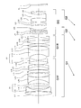
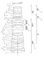
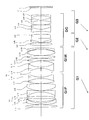
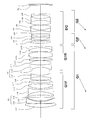
- FIG. 1 is a sectional view of the optical system according to the first embodiment.
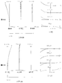
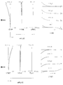
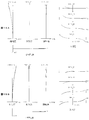
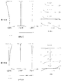
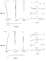
- 2A and 2B are graphs showing various aberrations of the optical system according to Example 1 when focusing on an object at infinity and when focusing on a short-distance object, respectively.
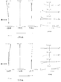
- FIGS. 3A and 3B are aberration diagrams of the optical system according to the first example when the DC unit moves to the object side and the DC unit moves to the image side when focusing on an object at infinity.
- 4A and 4B are graphs showing various aberrations in a state where the DC group moves to the object side and a state where the DC group moves to the image side when the optical system according to the first example focuses on a short-distance object. .
- FIG. 1 is a sectional view of the optical system according to the first embodiment.
- 2A and 2B are graphs showing various aberrations of the optical system according to Example 1 when focusing on an object at infinity and when focusing on a short-distance object, respectively.
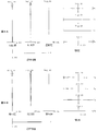
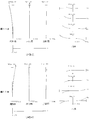
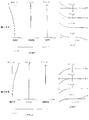
- FIGS. 6A and 6B are graphs showing various aberrations of the optical system according to Example 2 when focusing on an object at infinity and when focusing on a close object.
- 7A and 7B are graphs showing various aberrations when the DC unit moves to the object side and the DC unit moves to the image side when the optical system according to Example 2 is focused on an object at infinity.
- 8A and 8B are graphs showing various aberrations in a state where the DC unit moves to the object side and a state where the DC unit moves to the image side when the optical system according to the second example focuses on a short-distance object.
- FIG. 9 is a sectional view of an optical system according to the third example.
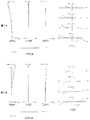
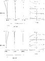
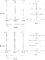
- FIGS. 10A and 10B are graphs showing various aberrations of the optical system according to Example 3 upon focusing on an object at infinity and on focusing on a close object.
- FIGS. 11A and 11B are graphs showing various aberrations in a state where the DC group moves to the object side and a state where the DC group moves to the image side when the optical system according to Example 3 is focused on an object at infinity.
- . 12A and 12B are graphs showing various aberrations when the DC unit moves to the object side and the DC unit moves to the image side when the optical system according to Example 3 is focused on a short-distance object.
- FIG. 13 is a sectional view of an optical system according to the fourth example.
- FIGS. 14A and 14B are graphs showing various aberrations of the optical system according to Example 4 when focusing on an object at infinity and when focusing on a short-distance object, respectively.
- FIGS. 15A and 15B are graphs showing various aberrations when the optical system according to Example 4 is focused on an object at infinity and the DC unit is moved to the object side and the DC unit is moved to the image side.
- . 16A and 16B are aberration diagrams of the optical system according to Example 4 when the DC unit is moved to the object side and when the DC unit is moved to the image side when a short-distance object is focused.
- FIG. 17 is a sectional view of an optical system according to the fifth example.
- FIG. 18A and 18B are graphs showing various aberrations of the optical system according to Example 5 upon focusing on an object at infinity and upon focusing on a close object.
- 19A and 19B are graphs showing various aberrations in a state where the DC group moves to the object side and a state where the DC group moves to the image side when the optical system according to Example 5 is focused on an object at infinity.
- 20A and 20B are graphs showing various aberrations in a state where the DC unit moves to the object side and a state where the DC unit moves to the image side when the optical system according to the fifth example focuses on a short-distance object.
- FIG. 21 is a sectional view of the optical system according to the sixth example.
- FIGS. 22A and 22B are graphs showing various aberrations of the optical system according to Example 6 upon focusing on an object at infinity and upon focusing on an object at a short distance.
- FIGS. 23A and 23B are graphs showing various aberrations in a state where the DC unit moves to the object side and a state where the DC unit moves to the image side when the optical system according to the sixth example is focused on an object at infinity.
- FIGS. 24A and 24B are graphs showing various aberrations when the DC unit moves to the object side and the DC unit moves to the image side when the optical system according to Example 6 is focused on a short-distance object.
- FIG. 25 is a diagram illustrating a configuration of a camera including an optical system.
- FIG. 26 is a flowchart showing an outline of a method of manufacturing an optical system.
- the optical system according to the present embodiment includes, in order from the object side, a first lens group having a positive refractive power and a plurality of subsequent lens groups. During focusing, an interval between adjacent lens groups changes.
- the first lens group includes a front lens group having a positive refractive power disposed on the object side, and a rear lens group having a positive refractive power disposed on the image side, with the aperture stop interposed therebetween.
- the front lens group moves to the object side when focusing from an object at infinity to an object at a short distance.
- the optical system of the present embodiment can satisfactorily correct various aberrations, particularly spherical aberration and coma, from the in-focus state of an object at infinity to the in-focus state of a close object.
- the rear lens group is configured such that m and n are positive integers satisfying m ⁇ n, and the rear lens group is arranged from the most object side lens surface of the rear lens group.
- h (m) and h (n) are positive integers satisfying m ⁇ n
- h (m)> h (n) is satisfied.
- the highest h (m) is h (max) and the lowest h (n) is h (min)
- the following conditional expression (1) is satisfied. (1) 0.50 ⁇ h (min) / h (max)
- marginal ray refers to a ray having the highest incident light among incident light fluxes parallel to the optical axis.
- the “marginal ray height” is the distance from the optical axis to the marginal ray (the distance in a direction perpendicular to the optical axis).
- Conditional expression (1) is a conditional expression that defines the ratio between the lowest marginal ray height and the highest marginal ray height in the rear lens unit.
- conditional expression (1) of the present embodiment When the corresponding value of the conditional expression (1) of the present embodiment is below the lower limit, the height of the marginal ray on the object-side lens surface of the rear lens unit becomes low, and the spherical aberration and coma aberration in the rear lens unit become good. It becomes difficult to make corrections.
- the lower limit of conditional expression (1) By setting the lower limit of conditional expression (1) to 0.60, the effect of the present embodiment can be made more reliable.
- the optical system of the present embodiment can satisfactorily correct various aberrations from an in-focus object state to a close-distance object focus state, and is suitable for both auto focus and manual focus.
- a large-diameter optical system can be realized.
- the optical system includes, in order from the object side, a first lens group having a positive refractive power and a plurality of subsequent lens groups. During focusing, an interval between adjacent lens groups changes.
- the first lens group includes a front lens group having a positive refractive power disposed on the object side, and a rear lens group having a positive refractive power disposed on the image side, with the aperture stop interposed therebetween.
- the front lens group moves to the object side when focusing from an object at infinity to an object at a short distance.
- the optical system according to the present embodiment can satisfactorily correct various aberrations, particularly spherical aberration and coma, from an in-focus object state to a close-distance object focus state.
- the front lens unit sets the marginal ray height of the front lens unit at the most object side lens surface at the time of focusing on an object at infinity to h (1).
- m and n are integers of 2 or more satisfying m ⁇ n, and the marginal ray heights at the m-th and n-th lens surfaces counted from the lens surface closest to the object are h (m) and h (m), respectively.
- Conditional expression (2) represents the difference between the highest marginal ray height and the lowest marginal ray height in the front lens group, and the marginal ray height and the lowest marginal ray height of the most object side lens surface of the front lens group. It is a conditional expression which defines the ratio with the difference.
- conditional expression (2) the distance between the marginal ray and the optical axis becomes shorter after passing through the lens surface closest to the object side of the front lens group before the aperture stop, and thereafter, Takes an optical path that increases the distance of
- the optical system according to the present embodiment can reduce Petzval sum by providing an area in which the marginal ray height is lower in front of the aperture stop, and can correct field curvature satisfactorily.
- conditional expression (2) of the present embodiment If the corresponding value of the conditional expression (2) of the present embodiment is below the lower limit, the area where the marginal ray height is low is not sufficiently formed, so that the Petzval sum cannot be sufficiently reduced, and the field curvature is good. It becomes difficult to make corrections.
- the lower limit of conditional expression (2) By setting the lower limit of conditional expression (2) to 0.12, the effect of the present embodiment can be made more reliable. In order to further secure the effect of the present embodiment, it is preferable to set the lower limit of conditional expression (2) to 0.15, more preferably 0.18.
- the optical system of the present embodiment can satisfactorily correct various aberrations from an in-focus object state to a close-distance object focus state, and is suitable for both auto focus and manual focus.
- a large-diameter optical system can be realized.
- the rear lens group includes at least one or more lens groups that move during focusing.
- the rear lens group includes at least two negative lenses and at least two positive lenses.
- the optical system according to the present embodiment has a configuration in which at least two negative lenses and at least two positive lenses are provided in the rear lens group adjacent to the rear side of the aperture stop. , And the curvature of field can be more favorably corrected.
- the “lens component” refers to a cemented lens formed by joining two or more lenses, or a single lens.
- the front lens group has at least four lens components.
- spherical aberration and coma can be effectively reduced irrespective of the focusing distance.
- the first lens group includes at least one negative lens satisfying the following conditional expression (3).
- (3) 0.600 ⁇ gFLn + 0.0021 ⁇ ⁇ dLn ⁇ 0.658
- ⁇ dLn Abbe number of the negative lens with respect to d-line
- ⁇ gFLn partial dispersion ratio between the g-line and the F-line of the negative lens
- the Abbe number ⁇ dLn and the partial dispersion ratio ⁇ gFLn are nC for the refractive index for the C line (wavelength 656.3 nm), nd for the refractive index for the d line (wavelength 587.6 nm), and nd for the F line (wavelength 486.1 nm).
- the refractive index is nF
- the refractive index with respect to the g-line is ng
- ⁇ dLn (nd ⁇ 1) / (nF ⁇ nC)
- ⁇ gFLn (ng ⁇ nF) / (nF ⁇ nC)
- conditional expression (3) is a conditional expression that defines a glass material used for the negative lens of the first lens group.
- conditional expression (3) of the optical system according to the present embodiment exceeds the upper limit, the anomalous dispersion of the negative lens increases, and it becomes difficult to correct axial chromatic aberration.
- the upper limit of conditional expression (3) it is preferable to set the upper limit of conditional expression (3) to 0.656, more preferably 0.655.
- conditional expression (3) of the optical system according to the present embodiment when the corresponding value of the conditional expression (3) of the optical system according to the present embodiment is below the lower limit, the anomalous dispersion of the negative lens becomes small, and it becomes difficult to correct axial chromatic aberration.
- the lower limit of conditional expression (3) By setting the lower limit of conditional expression (3) to 0.610, the effect of the present embodiment can be further ensured.
- the optical system of the present embodiment satisfies the following conditional expression (4).
- f (1F to 1R) composite focal length of the front lens group and the rear lens group when focusing on an object at infinity
- f focal length of the entire optical system when focusing on an object at infinity
- Conditional expression (4) defines a composite focal length of the front lens group and the rear lens group when focusing on an object at infinity, that is, a focal length of the first lens group when focusing on an object at infinity, and an object at infinity. It is a conditional expression which specifies the ratio with the focal length of the whole optical system at the time of focusing.
- conditional expression (4) of the optical system according to the present embodiment exceeds the upper limit, the refractive power of the first lens group becomes weak, and it becomes difficult to satisfactorily correct spherical aberration and coma. .
- the upper limit of conditional expression (4) it is preferable to set the upper limit of conditional expression (4) to 1.300, 1.250, 1.200, and more preferably 1.150.
- the corresponding value of the conditional expression (4) of the optical system according to the present embodiment is below the lower limit, the power of the first lens unit becomes strong, and it becomes difficult to satisfactorily correct coma.
- the lower limit of conditional expression (4) it is preferable to set the lower limit of conditional expression (4) to 0.850, more preferably 0.880, 0.900 and 0.920.
- the optical system according to the present embodiment includes, in order from the object side, a first set that is a set of lenses whose concave surfaces face each other, and a second set that is a set of lenses whose concave surfaces face each other. Having at least one positive lens between the first set and the second set, having at least one positive lens on the object side of the first set, There are at least four positive lenses on the side, and three or more types of glass materials are used.
- the optical system according to the present embodiment includes, in order from the object side, a first set that is a set of lenses whose concave surfaces face each other, and a second set that is a set of lenses whose concave surfaces face each other, By arranging at least one positive lens between the two sets of lenses, the first set and the second set contribute to reducing the Petzval sum, thereby favorably correcting the field curvature. At the same time, the deterioration of coma and spherical aberration is suppressed.
- the optical system of the present embodiment reduces the height of off-axis light rays incident on the first set by arranging at least one positive lens on the object side of the first set.
- the refractive powers of the first set and the second set are set to appropriate values, and the amount of coma is suppressed to an amount that can be corrected by other lens groups.
- the optical system according to the present embodiment can satisfactorily correct spherical aberration by having at least four positive lenses on the image side of the second set.
- the optical system according to the present embodiment can satisfactorily correct various aberrations such as chromatic aberration by using three or more types of glass materials.
- the optical system of the present embodiment can further effectively reduce the Petzval sum and correct the field curvature more favorably by satisfying the following conditional expressions (5) to (8).
- (5) 0.30 ⁇ R1 / f ⁇ 0.80 (6) 0.30 ⁇ R3 / f ⁇ 0.80 (7) -0.80 ⁇ (R1 + R2) / (R1-R2) ⁇ 0.80 (8) -0.80 ⁇ (R3 + R4) / (R3-R4) ⁇ 0.80
- f focal length of the entire optical system at the time of focusing on an object at infinity
- R1 radius of curvature of the concave surface on the object side among the facing concave surfaces of the first set
- R2 of the facing concave surface of the first set
- the radius of curvature R3 of the concave surface on the image side is the radius of curvature R4 of the concave surface on the object side among the concave surfaces facing each other in the second set.
- Conditional expression (5) is a conditional expression that defines the ratio between the radius of curvature of the concave surface on the object side and the focal length of the entire optical system among the concave surfaces facing each other in the first set.
- Conditional expression (6) is a conditional expression that defines the ratio between the radius of curvature of the concave surface on the object side and the focal length of the entire optical system among the opposing concave surfaces of the second set.
- Conditional expression (7) is a conditional expression for defining the shape factor of the concave surface facing the first set.
- Conditional expression (8) is a conditional expression for defining the shape factor of the concave surface facing the second set.
- the effect of the present embodiment can be further ensured.
- the lower limit of conditional expression (5) it is preferable to set the lower limit of conditional expression (5) to 0.400, more preferably 0.450.
- the effect of the present embodiment can be further ensured.
- the lower limit of conditional expression (6) it is preferable to set the lower limit of conditional expression (6) to 0.400, more preferably 0.450.
- the effect of the present embodiment can be further ensured.
- the lower limit of conditional expression (7) it is preferable to set the lower limit of conditional expression (7) to -0.700, -0.650, and more preferably -0.600.
- the effect of the present embodiment can be further ensured.
- the lower limit of conditional expression (8) it is preferable to set the lower limit of conditional expression (8) to -0.500, -0.300, and more preferably -0.100.
- the optical system of the present embodiment satisfies the following conditional expression (9). (9) 0.100 ⁇ f / ( ⁇ f1) ⁇ 1.000
- f focal length of the entire optical system at the time of focusing on an object at infinity
- f1 all lenses from the lens component closest to the object to the second negative lens component from the object side in the entire optical system
- Conditional expression (9) represents the combined focal length of all lens components from the lens component closest to the object side to the second negative lens component from the object side in the entire optical system, and the focal length of the entire optical system. It is a conditional expression for defining the ratio with the distance. By satisfying conditional expression (9), it is possible to suppress the deterioration of coma and spherical aberration while effectively reducing the Petzval sum, and as a result, it is possible to satisfactorily correct field curvature.
- conditional expression (9) of the optical system according to the present embodiment exceeds the upper limit, the Petzval sum cannot be reduced effectively, and it becomes difficult to satisfactorily correct the field curvature. .
- the upper limit of conditional expression (9) it is preferable to set the upper limit of conditional expression (9) to 0.900, more preferably 0.850.
- conditional expression (9) of the optical system according to the present embodiment falls below the lower limit, the spherical aberration and the coma become worse.
- the lower limit of conditional expression (9) it is preferable to set the lower limit of conditional expression (9) to 0.200, more preferably 0.250.
- the optical system of the present embodiment satisfies the following conditional expression (10). (10) 12.0 ° ⁇ 2 ⁇ ⁇ 40.0 ° However, 2 ⁇ : angle of view of the optical system when focusing on an object at infinity
- Conditional expression (10) is a condition for defining the optimum value of the angle of view.
- the optical system of the present embodiment can satisfy the requirement for downsizing of the entire optical system and satisfactory optical performance.
- the upper limit of conditional expression (10) it is preferable to set the upper limit of conditional expression (10) to 35.0 °. In order to further secure the effect of the present embodiment, it is preferable to set the upper limit of conditional expression (10) to 30.0 °, 28.0 °, and further preferably 25.0 °. In order to secure the effect of the present embodiment, it is preferable to set the lower limit of conditional expression (10) to 13.0 °. In order to further secure the effect of the present embodiment, it is preferable to set the lower limit of conditional expression (10) to 15.0 °, 18.0 °, and further preferably 21.0 °.
- the optical system of the present embodiment satisfies the following conditional expression (11).
- (11) 0.100 ⁇ bfa / f ⁇ 0.250
- bfa the air-equivalent distance on the optical axis from the image side lens surface of the lens closest to the image side to the image plane
- f the focal length of the entire optical system at the time of focusing on an object at infinity
- conditional expression (11) defines a ratio between the air-equivalent distance on the optical axis from the image-side lens surface of the lens closest to the image side to the image plane and the focal length of the entire optical system. It is. By satisfying conditional expression (11), it is possible to reduce the size of the entire optical system and to satisfy good optical performance.
- conditional expression (11) of the optical system according to the present embodiment exceeds the upper limit, the entire optical system becomes large in the radial direction due to a large numerical aperture, and it becomes difficult to correct the field curvature.
- the upper limit of conditional expression (11) it is preferable to set the upper limit of conditional expression (11) to 0.195, 0.185, and more preferably 0.182.
- conditional expression (11) of the optical system according to the present embodiment falls below the lower limit
- the diameter of the final lens unit becomes large due to the peripheral light beam, and a strong negative power is applied to reduce the size of the entire optical system. Is required on the rear side, and it is particularly difficult to correct spherical aberration.
- the lower limit of conditional expression (11) it is preferable to set the lower limit of conditional expression (11) to 0.120, 0.130, and more preferably 0.140.
- the optical system according to the present embodiment includes a DC group in which the subsequent lens group changes the blur of a defocus area by moving along the optical axis, and the DC group in focusing on an object at infinity.
- ⁇ DC is the image plane movement coefficient which is the ratio of the image plane movement amount to the movement amount in the optical axis direction.
- the optical system according to the present embodiment includes a DC group that changes the blur in the defocus area by moving along the optical axis, and satisfies the conditional expression (12), so that undesired coma aberration in the blur is obtained. , Astigmatism, chromatic aberration and the like are minimized, and only spherical aberration is changed. Further, the optical system according to the present embodiment can change the spherical aberration to both positive and negative by moving the DC group in the optical axis direction and changing the distance between the DC group and the lens groups before and after the DC group.
- the direction of movement of the DC group along the optical axis is such that the direction toward the image side is a positive direction and the direction toward the object side is a negative direction.
- Conditional expression (12) is a conditional expression that defines the ratio of the moving amount of the image plane to the moving amount of the DC group in the optical axis direction.
- conditional expression (12) it is possible to reduce the amount of refocusing when the DC group is moved in the optical axis direction to change mainly the spherical aberration. As a result, it is possible to suppress the aberration fluctuation at the time of re-focusing.
- the image plane movement coefficient ⁇ DC which is the ratio of the amount of movement of the image plane to the amount of movement of the DC group in the optical axis direction when focusing on an object at infinity, is defined by the following equation.
- ⁇ DC (1 ⁇ DC 2 ) ⁇ ⁇ R 2
- ⁇ DC lateral magnification of the DC group
- ⁇ R lateral magnification of the lens group on the image side of the DC group
- the back focus greatly fluctuates when the DC group is moved in the optical axis direction. It is necessary to move the focus group again greatly. As a result, coma aberration and curvature of field mainly fluctuate due to aberration fluctuations caused by focusing, which is not desirable.
- the effect of the present embodiment can be made more reliable.
- the lower limit of conditional expression (12) By setting the lower limit of conditional expression (12) to -0.450, the effect of the present embodiment can be further ensured.
- optical system of the present embodiment satisfies the following conditional expression (13). (13) 0.700 ⁇ DC ⁇ 1.300 However, ⁇ DC: lateral magnification of the DC group
- Conditional expression (13) is a conditional expression that defines the lateral magnification of the DC group. By satisfying conditional expression (13), it is possible to suppress excessive enlargement or excessive reduction of aberration of the lens unit on the object side of the DC unit.
- conditional expression (13) of the optical system according to the present embodiment exceeds the upper limit, the aberration of the lens unit on the object side relative to the DC unit is excessively enlarged, so that coma other than spherical aberration, field curvature, and axial aberration are caused. Large chromatic aberration, chromatic aberration of magnification, and the like also occur largely.
- the upper limit of conditional expression (13) it is preferable to set the upper limit of conditional expression (13) to 1.200, more preferably 1.150.
- conditional expression (13) of the optical system according to the present embodiment when the corresponding value of the conditional expression (13) of the optical system according to the present embodiment is below the lower limit, it is difficult to generate a predetermined spherical aberration even if the DC group is moved in the optical axis direction. As a result, it is necessary to move the DC group largely in the optical axis direction, and coma other than spherical aberration, curvature of field, axial chromatic aberration, chromatic aberration of magnification, and the like are largely generated.
- the lower limit of conditional expression (13) By setting the lower limit of conditional expression (13) to 0.750, the effect of the present embodiment can be further ensured. In order to further secure the effect of the present embodiment, it is preferable to set the lower limit of conditional expression (13) to 0.800, more preferably 0.850.
- the optical system according to the present embodiment includes a DC group in which the subsequent lens group changes the blur of a defocus area by moving along the optical axis, and the DC group in focusing on an object at infinity.
- ⁇ DC the amount of change in spherical aberration in the longitudinal aberration display corresponding to ⁇ DC is ⁇ SA, and the maximum aperture when the DC group does not move in the optical axis direction when an object at infinity is in focus. It is desirable that the following conditional expression (14) is satisfied, where F is the Fin value. (14) 0.300 ⁇
- Conditional expression (14) defines the ratio of the amount of movement of the DC group when the DC group is moved in the optical axis direction during focusing on an object at infinity to the amount of change in spherical aberration that changes due to this movement of the DC group. Is a conditional expression to be performed.
- conditional expression (14) By satisfying conditional expression (14), a large change in spherical aberration can be realized even when the DC group moves in a relatively small direction along the optical axis.
- the way light rays pass through each lens group does not change much compared to when the DC group is not moved, so that it is possible to suppress fluctuations in aberrations other than spherical aberration when the DC group is moved. Become.
- conditional expression (14) of the optical system according to the present embodiment exceeds the upper limit, when the DC group is moved, coma other than spherical aberration, field curvature, and axial chromatic aberration also occur largely. .
- the upper limit of conditional expression (14) it is preferable to set the upper limit of conditional expression (14) to 2.000, 1.800, and more preferably 1.500.
- conditional expression (14) of the optical system according to the present embodiment falls below the lower limit, it is necessary to largely move the DC group in the optical axis direction in order to realize a predetermined change in spherical aberration. .
- the way light rays pass through each lens group is significantly different from that when the DC group is not moved, so that coma aberration and field curvature in particular vary greatly.
- the lower limit of conditional expression (14) it is preferable to set the lower limit of conditional expression (14) to 0.400, 0.450, and more preferably 0.500.
- the optical system according to the present embodiment includes the DC group in which the subsequent lens group changes the blur of the defocus area by moving along the optical axis, and the DC group in focusing on a short-distance object.
- the amount of movement of the DC group in the optical axis direction as ⁇ DC is the amount of change in spherical aberration in the longitudinal aberration display corresponding to the ⁇ DC is ⁇ SA, and the maximum aperture when the DC group does not move in the optical axis direction when a short-distance object is focused.
- Is Fmod it is desirable to satisfy the following conditional expression (15). (15) 2.000 ⁇
- Conditional expression (15) defines the ratio between the amount of movement of the DC group when the DC group is moved in the optical axis direction when a short-distance object is focused and the amount of change in spherical aberration that changes due to this movement of the DC group. Is a conditional expression to be performed.
- conditional expression (15) a large change in spherical aberration can be realized even with a relatively small movement of the DC group in the optical axis direction.
- the way light rays pass through each lens group does not change much compared to when the DC group is not moved, so that it is possible to suppress fluctuations in aberrations other than spherical aberration when the DC group is moved. Become.
- conditional expression (15) of the optical system according to the present embodiment exceeds the upper limit, when the DC group is moved, coma other than spherical aberration, field curvature, and axial chromatic aberration also occur greatly. .
- the upper limit of conditional expression (15) it is preferable to set the upper limit of conditional expression (15) to 10.000, further preferably 9.000.
- conditional expression (15) of the optical system according to the present embodiment falls below the lower limit, it is necessary to largely move the DC group in the optical axis direction in order to realize a predetermined change in spherical aberration. .
- the way light rays pass through each lens group is significantly different from that when the DC group is not moved, so that coma aberration and field curvature in particular vary greatly.
- the lower limit of conditional expression (15) it is preferable to set the lower limit of conditional expression (15) to 2.700, and more preferably to 3.000.
- the lens group closest to the image is the DC group.
- the optical apparatus of the present embodiment has the optical system having the above-described configuration. This makes it possible to satisfactorily correct various aberrations from the in-focus state of an object at infinity to the in-focus state of a close object, and to provide an optical apparatus having a large-diameter optical system suitable for both auto focus and manual focus. Can be realized.
- the method for manufacturing an optical system according to the present embodiment is a method for manufacturing an optical system including a first lens group having a positive refractive power and a plurality of subsequent lens groups in order from the object side. The distance between the adjacent lens groups is changed, and the first lens group is disposed on the image side with the front lens group having a positive refractive power disposed on the object side with the aperture stop interposed therebetween.
- a rear lens group having a positive refractive power the front lens group is configured to move to the object side when focusing from an object at infinity to a close object
- the rear lens unit sets m and n to be positive integers satisfying m ⁇ n, and focuses on an object at infinity at m-th and n-th lens surfaces counted from the most object-side lens surface of the rear lens unit.
- FIG. 1 is a cross-sectional view of the optical system according to Example 1 upon focusing on an object at infinity. Arrows in FIG. 1 and FIGS. 5, 9, 13, 17, and 21 to be described later indicate the movement trajectories of the respective lens groups when focusing from an object at infinity to an object at a short distance. .
- the optical system according to this example includes, in order from the object side, a first lens group G1 having a positive refractive power, a second lens group G2 having a positive refractive power, and a third lens group having a negative refractive power. G3.
- the first lens group G1 includes a front lens group G1F having a positive refractive power disposed on the object side and a rear lens group G1R having a positive refractive power disposed on the image side with the aperture stop S interposed therebetween. It is composed of
- the front lens group G1F includes, in order from the object side, a biconvex positive lens L11, a biconcave negative lens L12, a plano-convex lens L13 having a convex surface facing the object side, and a positive meniscus having a concave surface facing the object side.
- the rear lens group G1R includes, in order from the object side, a cemented negative lens composed of a biconcave negative lens L112 and a biconvex positive lens L113, a plano-convex lens L114 having a convex surface facing the image side, and a biconvex lens. It comprises a positive lens L115, a cemented positive lens composed of a plano-convex lens L116 with a convex surface facing the image side, and a negative meniscus lens L117 with a concave surface facing the object side.
- the biconcave negative lens L12 and the positive meniscus lens L14 with the concave surface facing the object side constitute a first lens set C1 with the concave surfaces facing each other.
- the biconcave negative lens L111 and the biconcave negative lens L112 form a second lens set C2 whose concave surfaces face each other.
- a plano-convex lens L13 is included between the negative lens L12 and the positive meniscus lens L14, the “set of lenses having concave surfaces facing each other” in the present embodiment includes a lens component having a simple configuration therebetween. Sometimes.
- the second lens group G2 includes, in order from the object side, a biconvex positive lens L21, a plano-convex lens L22 having a convex surface facing the object side, and a negative meniscus lens L23 having a convex surface facing the object side.
- the third lens group G3 includes, in order from the object side, a cemented negative lens composed of a biconcave negative lens L31 and a biconvex positive lens L32, a biconvex positive lens L33, and a biconcave negative lens L34. And a negative meniscus lens L35 having a concave surface facing the object side.
- a filter group FL composed of a low-pass filter or the like is arranged between the third lens group G3 and the image plane I.
- an image pickup device (not shown) composed of a CCD, a CMOS or the like is arranged on the image plane I.
- the optical system according to the present embodiment moves the first lens group G1, the second lens group G2, and the third lens group G3 along the optical axis along different trajectories toward the object side, thereby moving the object from an object at infinity. Focusing on a close object. At this time, the front lens group G1F and the rear lens group G1R of the first lens group G1 move integrally to the object side.
- the optical system according to the present embodiment has a DC group for changing the spherical aberration mainly by moving along the optical axis to the most image side and changing the blur of the defocus area.
- the second lens group G2 and the third lens group G3 move along the optical axis as a DC group.
- the second lens group G2 and the third lens group move along the optical axis as a DC group, they move together as one lens group.
- the optical system according to the present embodiment moves the DC group toward the object from the state where the amount of movement of the DC group in the optical axis direction is 0 (zero), that is, the state where the spherical aberration is satisfactorily corrected, that is, By moving in the direction, the spherical aberration can be changed in a direction in which correction is insufficient.
- the spherical aberration is changed in a direction in which correction is excessive. be able to.
- Table 1 below lists values of specifications of the optical system according to the present embodiment.
- f indicates the focal length
- BF indicates the back focus, that is, the distance on the optical axis from the lens surface closest to the image side to the image plane I.
- m is the order of the optical surfaces counted from the object side
- r is the radius of curvature
- d is the surface interval (the interval between the nth surface (n is an integer) and the (n + 1) th surface)
- nd is the d line ( The refractive index with respect to a wavelength of 587.6 nm) and ⁇ d indicate the Abbe number with respect to the d line (with a wavelength of 587.6 nm).
- CE (1) indicates the values of h (max) and h (min) on the lens surface where the marginal ray height is h (max) and h (min) with respect to conditional expression (1)
- CE (2) Is the value of h (1), h (max) h and (min) on the lens surface where the marginal ray height is h (1), h (max) and h (min) with respect to conditional expression (2)
- CE (3) indicates a value corresponding to conditional expression (3) in a negative lens satisfying conditional expression (3).
- [Aspherical surface data] shows an aspherical surface coefficient and a conical constant when the shape of the aspherical surface shown in [surface data] is represented by the following equation.
- x (h 2 / r) / [1+ ⁇ 1- ⁇ (h / r) 2 ⁇ 1/2 ] + A4h 4 + A6h 6 + A8h 8 + A10h 10 + A12h 12 + A14h 14
- h is the height in the direction perpendicular to the optical axis
- x is the distance along the optical axis from the tangent plane of the vertex of the aspheric surface at the height h to the aspheric surface
- ⁇ is the conic constant
- A4, A6, A8, A10, A12, A14 are aspherical coefficients
- r is a paraxial radius of curvature which is the radius of curvature of the reference spherical surface.
- en (n: an integer) indicates “ ⁇ 10 ⁇ n ”, and for example, “1.234e-05” indicates “1.234 ⁇ 10 ⁇ 5 ”.
- the second-order aspheric coefficient A2 is 0, and the description is omitted.
- f is the focal length of the entire optical system
- FNo is the F number
- ⁇ is the half angle of view (unit is “°”)
- Y is the maximum image height
- TL is the optical system according to the present embodiment.
- the total length that is, the distance on the optical axis from the first surface to the image plane I, and the BF (air conversion length) indicate the BF obtained by converting the thickness of the filter group FL into air.
- Finf indicates the F value of the maximum aperture when the DC group does not move in the optical axis direction during focusing on an object at infinity, that is, when the amount of movement of the DC group in the optical axis direction is 0 (zero)
- Fmod indicates the F value of the maximum aperture when the DC group does not move in the optical axis direction when a short-distance object is focused, that is, when the amount of movement of the DC group in the optical axis direction is 0 (zero).
- D0 is the distance from the object to the lens surface closest to the object
- ⁇ is the closest photographing magnification
- f is the focal length of the entire optical system
- Dn (n is an integer) is the nth surface and the (n + 1) th.
- INF indicates the time of focusing on an object at infinity
- CLO indicates the time of focusing on an object at a short distance
- INFDC (-) indicates that the object is in focus at infinity and the DC group has moved to the object side
- INFDC (+) indicates that the object has focus at infinity and the DC group has moved to the image plane I side.
- CLODC (+) is in focus on a short-distance object and the DC group has moved to the object side
- CLODC (+) is in focus on a short-distance object and the DC group has moved to the image plane I side
- [Lens group data] indicates the starting surface number ST and the focal length f of each lens group.
- [Conditional expression corresponding value] shows the corresponding value of each conditional expression.
- the unit of the focal length f, the radius of curvature r and other lengths shown in Table 1 is generally “mm”.
- the optical system is not limited to this, since the same optical performance can be obtained even if the optical system is proportionally enlarged or proportionally reduced. Note that the reference numerals in Table 1 described above are used in the same manner in the tables of each embodiment described later.
- FIGS. 2A and 2B are graphs showing various aberrations when the DC group is not moved when the optical system according to the first example is focused on an object at infinity and when focused on a short-distance object, respectively.
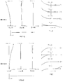
- FIGS. 3A and 3B are graphs showing various aberrations when the DC unit moves to the object side and the DC unit moves to the image side when the optical system according to the first example is focused on an object at infinity.
- FIGS. 4A and 4B are graphs showing various aberrations in a state where the DC group moves to the object side and a state where the DC group moves to the image side when the optical system according to the first example is focused on a short-distance object. is there.
- FNO indicates an F number
- Y indicates an image height
- NA indicates a numerical aperture
- the spherical aberration diagram shows the value of the F-number FNO or the numerical aperture NA corresponding to the maximum aperture
- the astigmatism diagram and the distortion diagram show the maximum value of the image height Y
- the lateral aberration diagram shows the maximum value of each image height. Indicates a value.
- d indicates an aberration curve at the d-line (wavelength 587.6 nm)
- g indicates an aberration curve at the g-line (wavelength 435.8 nm)
- those without descriptions indicate aberration curves at the d line.
- a solid line indicates a sagittal image plane, and a broken line indicates a meridional image plane.
- the lateral aberration diagram shows lateral aberration (coma aberration) at each image height Y. Note that the same reference numerals as in the present embodiment are used in the aberration diagrams of the embodiments described later.
- the optical system according to the present embodiment has excellent imaging performance by well correcting various aberrations from the time of focusing on an object at infinity to the time of focusing on a close object. You can see that it is doing.
- the optical system according to the present embodiment favorably suppresses the fluctuation of other aberrations while mainly changing only spherical aberration at the time of focusing on an object at infinity. You can see that there is.
- the optical system according to the present embodiment favorably suppresses the fluctuation of other aberrations while mainly changing only spherical aberration at the time of focusing on a short-distance object. You can see that there is.
- FIG. 5 is a cross-sectional view of the optical system according to Example 2 upon focusing on an object at infinity.
- the optical system according to this example includes, in order from the object side, a first lens group G1 having a positive refractive power, a second lens group G2 having a positive refractive power, and a third lens group having a negative refractive power. G3.
- the first lens group G1 includes a front lens group G1F having a positive refractive power disposed on the object side and a rear lens group G1R having a positive refractive power disposed on the image side with the aperture stop S interposed therebetween. It is composed of
- the front lens group G1F includes, in order from the object side, a biconvex positive lens L11, a biconcave negative lens L12, a biconvex positive lens L13, and a positive meniscus lens L14 having a concave surface facing the object side.
- a cemented negative lens with a biconcave negative lens L15, a biconvex positive lens L16, a positive meniscus lens L17 with a concave surface facing the object side, a plano-convex lens L18 with a convex surface facing the image side, and a It comprises a cemented negative lens with a concave meniscus lens L19 and a cemented negative lens with a biconvex positive lens L110 and a biconcave negative lens L111.
- the rear lens group G1R includes, in order from the object side, a cemented negative lens composed of a biconcave negative lens L112 and a biconvex positive lens L113, a plano-convex lens L114 having a convex surface facing the image side, and a biconvex lens. It comprises a positive lens L115, a cemented positive lens composed of a plano-convex lens L116 with a convex surface facing the image side, and a negative meniscus lens L117 with a concave surface facing the object side.
- the biconcave negative lens L12 and the positive meniscus lens L14 with the concave surface facing the object side constitute a first lens set C1 with the concave surfaces facing each other.
- the biconcave negative lens L111 and the biconcave negative lens L112 form a second lens set C2 whose concave surfaces face each other.
- a biconvex positive lens L13 is included between the negative lens L12 and the positive meniscus lens L14.
- the second lens group G2 includes, in order from the object side, a biconvex positive lens L21, a plano-convex lens L22 having a convex surface facing the object side, and a negative meniscus lens L23 having a convex surface facing the object side.
- the third lens group G3 includes, in order from the object side, a cemented negative lens composed of a biconcave negative lens L31 and a biconvex positive lens L32, a biconvex positive lens L33, and a biconcave negative lens L34. And a negative meniscus lens L35 having a concave surface facing the object side.
- a filter group FL composed of a low-pass filter or the like is arranged between the third lens group G3 and the image plane I.
- an image pickup device (not shown) composed of a CCD, a CMOS or the like is arranged on the image plane I.
- the optical system moves the first lens group G1, the second lens group G2, and the third lens group along the optical axis along different trajectories toward the object side, thereby moving the first lens group G1, the second lens group G2, and the third lens group G from an object at infinity. Focusing on a distance object. At this time, the front lens group G1F and the rear lens group G1R of the first lens group G1 move integrally to the object side.
- the optical system according to the present embodiment has a DC group for changing the spherical aberration mainly by moving along the optical axis to the most image side and changing the blur of the defocus area.
- the second lens group G2 and the third lens group G3 move along the optical axis as a DC group.
- the second lens group G2 and the third lens group move along the optical axis as a DC group, they move together as one lens group.
- the optical system according to the present embodiment moves the DC group toward the object from the state where the amount of movement of the DC group in the optical axis direction is 0 (zero), that is, the state where the spherical aberration is satisfactorily corrected, that is, By moving in the direction, the spherical aberration can be changed in a direction in which correction is insufficient.
- the spherical aberration is changed in a direction in which correction is excessive. be able to.
- Table 2 shows values of specifications of the optical system according to the present example.
- FIGS. 8A and 8B are graphs showing various aberrations when the optical system according to the second embodiment focuses on a short-distance object, with the DC group moved to the object side and the DC group moved to the image side. is there.
- the optical system according to the present example has excellent imaging performance by favorably correcting various aberrations from when focusing on an object at infinity to when focusing on a close object. You can see that it is doing.
- the optical system according to the present embodiment favorably suppresses the fluctuation of other aberrations while mainly changing only spherical aberration at the time of focusing on an object at infinity. You can see that there is.
- the optical system according to the present embodiment favorably suppresses fluctuations of other aberrations while mainly changing only spherical aberration at the time of focusing on a short-distance object. You can see that there is.
- FIG. 9 is a cross-sectional view of the optical system according to Example 3 upon focusing on an object at infinity.
- the optical system according to this example includes, in order from the object side, a first lens group G1 having a positive refractive power, a second lens group G2 having a positive refractive power, and a third lens group having a negative refractive power. G3.
- the first lens group G1 includes a front lens group G1F having a positive refractive power disposed on the object side and a rear lens group G1R having a positive refractive power disposed on the image side with the aperture stop S interposed therebetween. It is composed of
- the front lens group G1F includes, in order from the object side, a biconvex positive lens L11, a biconcave negative lens L12, a biconvex positive lens L13, and a positive meniscus lens L14 having a concave surface facing the object side.
- the rear lens group G1R includes, in order from the object side, a first partial group G1R1 having a negative refractive power and a second partial group G1R2 having a positive refractive power.
- the first subgroup G1R1 includes, in order from the object side, a cemented negative lens of a biconcave negative lens L112 and a biconvex positive lens L113, and a positive meniscus lens L114 having a concave surface facing the object side.
- the second subgroup G1R2 includes, in order from the object side, a biconvex positive lens L115, and a cemented negative lens formed by a biconvex positive lens L116 and a biconcave negative lens L117.
- the biconcave negative lens L12 and the positive meniscus lens L14 with the concave surface facing the object side constitute a first lens set C1 with the concave surfaces facing each other.
- the biconcave negative lens L111 and the biconcave negative lens L112 form a second lens set C2 whose concave surfaces face each other.
- a biconvex positive lens L13 is included between the negative lens L12 and the positive meniscus lens L14.
- the second lens group G2 includes, in order from the object side, a biconvex positive lens L21, a biconvex positive lens L22, and a negative meniscus lens L23 having a convex surface facing the object side.
- the third lens group G3 includes, in order from the object side, a cemented positive lens composed of a biconcave negative lens L31 and a biconvex positive lens L32, a biconvex positive lens L33, and a biconcave negative lens L34. And a negative meniscus lens L35 having a concave surface facing the object side.
- a filter group FL composed of a low-pass filter or the like is arranged between the third lens group G3 and the image plane I.
- an image pickup device (not shown) composed of a CCD, a CMOS or the like is arranged on the image plane I.
- the optical system according to this example includes a front lens group G1F, a first partial group G1R1 of the rear lens group G1R, a second partial group G1R2 of the rear lens group G1R, a second lens group G2, and a third lens group.
- the optical system according to the present embodiment has a DC group for changing the spherical aberration mainly by moving along the optical axis to the most image side and changing the blur of the defocus area.
- the second lens group G2 and the third lens group G3 move along the optical axis as a DC group.
- the second lens group G2 and the third lens group move along the optical axis as a DC group, they move together as one lens group.
- the optical system according to the present embodiment moves the DC group toward the object from the state where the amount of movement of the DC group in the optical axis direction is 0 (zero), that is, the state where the spherical aberration is satisfactorily corrected, that is, By moving in the direction, the spherical aberration can be changed in a direction in which correction is insufficient.
- the spherical aberration is changed in a direction in which correction is excessive. be able to.
- Table 3 shows values of specifications of the optical system according to the present example.
- FIGS. 10A and 10B are graphs showing various aberrations of the optical system according to Example 3 when focusing on an object at infinity and when focusing on a short-distance object, respectively.
- FIGS. 11A and 11B are graphs showing various aberrations when the DC unit moves to the object side and the DC unit moves to the image side when the optical system according to Example 3 is focused on an object at infinity.
- FIGS. 12A and 12B are graphs showing various aberrations when the optical system according to Example 3 focuses on a short-distance object, with the DC group moved to the object side and the DC group moved to the image side. is there.
- the optical system according to the present embodiment has excellent imaging performance by satisfactorily correcting various aberrations from when focusing on an object at infinity to when focusing on a close object. You can see that it is doing.
- the optical system according to the present embodiment favorably suppresses fluctuations of other aberrations while mainly changing only spherical aberration at the time of focusing on an object at infinity. You can see that there is.
- the optical system according to the present embodiment favorably suppresses fluctuations of other aberrations while mainly changing only spherical aberration during focusing on a short-distance object. You can see that there is.
- FIG. 13 is a sectional view of the optical system according to Example 4 when focusing on an object at infinity.
- the optical system according to this embodiment includes, in order from the object side, a first lens group G1 having a positive refractive power, a second lens group G2 having a negative refractive power, and a third lens group having a negative refractive power. G3.
- the first lens group G1 includes a front lens group G1F having a positive refractive power disposed on the object side and a rear lens group G1R having a positive refractive power disposed on the image side with the aperture stop S interposed therebetween. It is composed of
- the front lens group G1F includes, in order from the object side, a biconvex positive lens L11, a negative meniscus lens L12 having a convex surface facing the object side, a positive meniscus lens L13 having a convex surface facing the object side, and a concave surface facing the object side.
- the rear lens group G1R includes, in order from the object side, a cemented negative lens composed of a biconcave negative lens L110 and a biconvex positive lens LL111; a positive meniscus lens L112 having a concave surface facing the object side; And a cemented positive lens formed by a biconvex positive lens LL114 and a biconcave negative lens L115.
- the negative meniscus lens L12 having a convex surface facing the object side and the positive meniscus lens L14 having a concave surface facing the object side constitute a first lens set C1 whose concave surfaces face each other.
- the biconcave negative lens L19 and the biconcave negative lens L110 form a second lens set C2 whose concave surfaces face each other.
- a positive meniscus lens L13 is included between the negative meniscus lens L12 and the positive meniscus lens L14.
- the second lens group G2 includes, in order from the object side, a biconvex positive lens L21, a negative meniscus lens L22 having a convex surface facing the object side, a negative meniscus lens L23 having a convex surface facing the object side, and a biconvex lens. And a cemented positive lens with the positive lens L24.
- the third lens group G3 includes, in order from the object side, a cemented negative lens composed of a biconcave negative lens L31 and a biconvex positive lens L32, a biconvex positive lens L33, and a biconcave negative lens L34. And a negative meniscus lens L35 having a concave surface facing the object side.
- a filter group FL composed of a low-pass filter or the like is arranged between the third lens group G3 and the image plane I.
- an image pickup device (not shown) composed of a CCD, a CMOS or the like is arranged on the image plane I.
- the optical system moves the first lens group G1, the second lens group G2, and the third lens group along the optical axis along different trajectories toward the object side, thereby moving the first lens group G1, the second lens group G2, and the third lens group G from an object at infinity. Focusing on a distance object.
- the optical system according to the present embodiment has a DC group for changing the spherical aberration mainly by moving along the optical axis to the most image side and changing the blur of the defocus area.
- the second lens group G2 and the third lens group G3 move along the optical axis as a DC group.
- the second lens group G2 and the third lens group move along the optical axis as a DC group, they move together as one lens group.
- the optical system according to the present embodiment moves the DC group toward the object from the state where the amount of movement of the DC group in the optical axis direction is 0 (zero), that is, the state where the spherical aberration is satisfactorily corrected, that is, By moving in the direction, the spherical aberration can be changed in a direction in which correction is insufficient.
- the spherical aberration is changed in a direction in which correction is excessive. be able to.
- Table 4 shows values of specifications of the optical system according to the present example.
- FIGS. 14A and 14B are graphs showing various aberrations of the optical system according to Example 4 when focusing on an object at infinity and when focusing on a close object.
- FIGS. 15A and 15B are graphs showing various aberrations when the DC unit moves to the object side and the DC unit moves to the image side when the optical system according to Example 4 is focused on an object at infinity.
- . 16A and 16B are graphs showing various aberrations in a state where the DC unit moves to the object side and a state where the DC unit moves to the image side when the optical system according to the fourth example is in focus on a short-distance object. is there.
- the optical system according to the present embodiment has excellent imaging performance by well correcting various aberrations from the time of focusing on an object at infinity to the time of focusing on a close object. You can see that it is doing.
- the optical system according to the present embodiment favorably suppresses fluctuations of other aberrations while mainly changing only spherical aberration at the time of focusing on an object at infinity. You can see that there is.
- the optical system according to the present embodiment favorably suppresses the fluctuation of other aberrations while mainly changing only the spherical aberration at the time of focusing on a short-distance object. You can see that there is.
- FIG. 17 is a cross-sectional view of the optical system according to Example 5 upon focusing on an object at infinity.
- the optical system according to this example includes, in order from the object side, a first lens group G1 having a positive refractive power, a second lens group G2 having a positive refractive power, and a third lens group having a negative refractive power. G3.
- the first lens group G1 includes a front lens group G1F having a positive refractive power disposed on the object side and a rear lens group G1R having a positive refractive power disposed on the image side with the aperture stop S interposed therebetween. It is composed of
- the front lens group G1F includes, in order from the object side, a biconvex positive lens L11, a negative meniscus lens L12 having a convex surface facing the object side, a positive meniscus lens L13 having a convex surface facing the object side, and a concave surface facing the object side.
- a biconvex positive lens L11 a biconvex positive lens L11
- a negative meniscus lens L12 having a convex surface facing the object side
- a positive meniscus lens L13 having a convex surface facing the object side
- a concave surface facing the object side a concave surface facing the object side.
- the rear lens group G1R includes, in order from the object side, a cemented negative lens composed of a biconcave negative lens L19 and a biconvex positive lens LL110; a positive meniscus lens L111 having a concave surface facing the object side; LL112, a biconvex positive lens LL113, and a negative meniscus lens L114 having a concave surface facing the object side.
- the negative meniscus lens L12 having a convex surface facing the object side and the positive meniscus lens L14 having a concave surface facing the object side constitute a first lens set C1 whose concave surfaces face each other.
- the biconcave negative lens L18 and the biconcave negative lens L19 constitute a second lens set C2 whose concave surfaces face each other.
- a positive meniscus lens L13 is included between the negative meniscus lens L12 and the positive meniscus lens L14.
- the second lens group G2 includes, in order from the object side, a biconvex positive lens L21, a negative meniscus lens L22 having a convex surface facing the object side, and a positive meniscus lens L23 having a concave surface facing the object side.
- the third lens group G3 includes, in order from the object side, a cemented negative lens composed of a biconcave negative lens L31 and a biconvex positive lens L32, a biconvex positive lens L33, and a biconcave negative lens L34. And a negative meniscus lens L35 having a concave surface facing the object side.
- a filter group FL composed of a low-pass filter or the like is arranged between the third lens group G3 and the image plane I.
- an image pickup device (not shown) composed of a CCD, a CMOS or the like is arranged on the image plane I.
- the optical system moves the first lens group G1, the second lens group G2, and the third lens group along the optical axis along different trajectories toward the object side, thereby moving the first lens group G1, the second lens group G2, and the third lens group G from an object at infinity. Focusing on a distance object.
- the optical system according to the present embodiment has a DC group for changing the spherical aberration mainly by moving along the optical axis closest to the image side and changing the blurring of the defocus area.
- the second lens group G2 and the third lens group G3 move along the optical axis as a DC group.
- the second lens group G2 and the third lens group move along the optical axis as a DC group, they move together as one lens group.
- the optical system according to the present embodiment moves the DC group toward the object from the state where the amount of movement of the DC group in the optical axis direction is 0 (zero), that is, the state where the spherical aberration is satisfactorily corrected, that is, By moving in the direction, the spherical aberration can be changed in a direction in which correction is insufficient.
- the spherical aberration is changed in a direction in which correction is excessive. be able to.
- Table 5 shows values of specifications of the optical system according to the present example.
- FIGS. 19A and 19B are graphs showing various aberrations when the DC unit moves to the object side and the DC unit moves to the image side when the optical system according to Example 5 is focused on an object at infinity.
- 20A and 20B are graphs showing various aberrations in a state where the DC group moves to the object side and a state where the DC group moves to the image side when the optical system according to Example 5 is focused on a short-distance object. is there.
- the optical system according to the present embodiment has excellent imaging performance by favorably correcting various aberrations from the time of focusing on an object at infinity to the time of focusing on a close object. You can see that it is doing.
- the optical system according to the present embodiment favorably suppresses fluctuations of other aberrations while mainly changing only spherical aberration at the time of focusing on an object at infinity. You can see that there is.
- the optical system according to the present embodiment favorably suppresses fluctuations of other aberrations while mainly changing only spherical aberration during focusing on a short-distance object. You can see that there is.
- FIG. 21 is a sectional view of the optical system according to Example 6 upon focusing on an object at infinity.
- the optical system according to this embodiment includes, in order from the object side, a first lens group G1 having a positive refractive power, a second lens group G2 having a negative refractive power, and a third lens group having a negative refractive power. G3.
- the first lens group G1 includes a front lens group G1F having a positive refractive power disposed on the object side and a rear lens group G1R having a positive refractive power disposed on the image side with the aperture stop S interposed therebetween. It is composed of
- the front lens group G1F includes, in order from the object side, a biconvex positive lens L11, a negative meniscus lens L12 having a convex surface facing the object side, a positive meniscus lens L13 having a convex surface facing the object side, and a concave surface facing the object side.
- the rear lens group G1R includes, in order from the object side, a cemented negative lens composed of a biconcave negative lens L110 and a biconvex positive lens LL111; a positive meniscus lens L112 having a concave surface facing the object side; And a cemented negative lens of a positive lens LL114 having a biconvex shape and a negative meniscus lens L115 having a concave surface facing the object side.
- the negative meniscus lens L12 having a convex surface facing the object side and the positive meniscus lens L14 having a concave surface facing the object side constitute a first lens set C1 whose concave surfaces face each other.
- the biconcave negative lens L19 and the biconcave negative lens L110 form a second lens set C2 whose concave surfaces face each other.
- a positive meniscus lens L13 is included between the negative meniscus lens L12 and the positive meniscus lens L14.
- the second lens group G2 includes, in order from the object side, a biconvex positive lens L21, a negative meniscus lens L22 having a convex surface facing the object side, a biconcave negative lens L23, and a biconvex positive lens L24. And a cemented positive lens.
- the third lens group G3 includes, in order from the object side, a cemented positive lens composed of a biconcave negative lens L31 and a biconvex positive lens L32, a biconvex positive lens L33, and a biconcave negative lens L34. And a negative meniscus lens L35 having a concave surface facing the object side.
- a filter group FL composed of a low-pass filter or the like is arranged between the third lens group G3 and the image plane I.
- an image pickup device (not shown) composed of a CCD, a CMOS or the like is arranged on the image plane I.
- the optical system moves the first lens group G1, the second lens group G2, and the third lens group along the optical axis along different trajectories toward the object side, thereby moving the first lens group G1, the second lens group G2, and the third lens group G from an object at infinity. Focusing on a distance object.
- the optical system according to the present embodiment has a DC group for changing the spherical aberration mainly by moving along the optical axis to the most image side and changing the blur of the defocus area.
- the second lens group G2 and the third lens group G3 move along the optical axis as a DC group.
- the second lens group G2 and the third lens group move along the optical axis as a DC group, they move together as one lens group.
- the optical system according to the present embodiment moves the DC group toward the object from the state where the amount of movement of the DC group in the optical axis direction is 0 (zero), that is, the state where the spherical aberration is satisfactorily corrected, that is, By moving in the direction, the spherical aberration can be changed in a direction in which correction is insufficient.
- the spherical aberration is changed in a direction in which correction is excessive. be able to.
- Table 6 shows values of specifications of the optical system according to the present example.
- FIGS. 22A and 22B are aberration diagrams of the optical system according to Example 6 upon focusing on an object at infinity and upon focusing on a close object, respectively.
- FIGS. 23A and 23B are aberration diagrams of the optical system according to Example 6 when the DC unit is moved to the object side and when the DC unit is moved to the image side when focusing on an object at infinity.
- FIGS. 24A and 24B are graphs showing various aberrations in a state where the DC unit moves to the object side and a state where the DC unit moves to the image side when the optical system according to Example 6 is focused on a short-distance object. is there.
- the optical system according to the present example has excellent imaging performance by well correcting various aberrations from the time of focusing on an object at infinity to the time of focusing on a close object. You can see that it is doing.
- the optical system according to the present embodiment favorably suppresses fluctuations of other aberrations while mainly changing only spherical aberration at the time of focusing on an object at infinity. You can see that there is.
- the optical system according to the present embodiment favorably suppresses fluctuations of other aberrations while mainly changing only spherical aberration at the time of focusing on a short-distance object. You can see that there is.
- each of the above embodiments it is possible to satisfactorily correct various aberrations from an in-focus state of an object at infinity to an in-focus state of a close object, and a large-diameter optical system suitable for both auto focus and manual focus. Can be realized.
- the spherical aberration is mainly changed according to the user's intention to maintain sharp depiction of the focused object while maintaining the sharpness of the image.
- the bokeh of the background outside the depth of field or the foreground outside the depth of field can be changed.
- the present embodiment is not limited to this, and an optical system having another group configuration (for example, four groups) can be configured. .
- an optical system having another group configuration for example, four groups
- a configuration in which a lens or a lens group is added to the most object side or the most image side of the optical system of each of the above embodiments may be used.
- a lens or a lens group may be added between adjacent lens groups.
- the lens group may include at least one lens.
- each lens group is a focusing lens group.
- a focusing lens group can also be applied to autofocus, and is also suitable for driving by a motor for autofocus, for example, an ultrasonic motor, a stepping motor, a VCM motor, or the like.
- the whole or a part of any of the lens groups is moved so as to include a component in a direction perpendicular to the optical axis as an image stabilizing group, or a surface including the optical axis.
- a configuration in which vibration is prevented by rotating (swinging) inward is also possible.
- the aperture stop of the optical system of each of the above embodiments may be configured so that a role is substituted by a lens frame without providing a member as the aperture stop.
- the lens surface of the lens constituting the optical system of each of the above embodiments may be a spherical surface, a flat surface, or an aspheric surface.
- the lens surface is a spherical surface or a flat surface, lens processing and assembly adjustment are facilitated, and deterioration of optical performance due to errors in lens processing and assembly adjustment can be prevented. Further, even when the image plane is displaced, it is preferable because the deteriorating performance is small.
- the lens surface is an aspherical surface
- any of an aspherical surface by grinding, a glass molded aspherical surface obtained by molding glass into an aspherical shape with a mold, or a composite aspherical surface formed by forming a resin provided on the glass surface into an aspherical shape is used.
- the lens surface may be a diffractive surface, and the lens may be a gradient index lens (GRIN lens) or a plastic lens.
- GRIN lens gradient index lens
- an antireflection film having a high transmittance in a wide wavelength range may be provided on the lens surface of the lens constituting the optical system of each of the above embodiments. Thereby, flare and ghost can be reduced, and high optical performance with high contrast can be achieved.
- FIG. 25 is a diagram illustrating a configuration of a camera including the optical system according to the present embodiment.
- the camera 1 is an interchangeable lensless mirrorless camera including the optical system according to the first embodiment as the taking lens 2.
- the camera 1 In the camera 1, light from an unillustrated object (subject) is condensed by a photographing lens 2 and passes through an unillustrated OLPF (Optical Low Pass Filter) on an imaging surface of an imaging unit 3. To form a subject image. Then, the subject image is photoelectrically converted by a photoelectric conversion element provided in the imaging unit 3 to generate an image of the subject. This image is displayed on an EVF (Electronic view finder) 4 provided in the camera 1. This allows the photographer to observe the subject via the EVF 4. When a release button (not shown) is pressed by the photographer, the image of the subject generated by the imaging unit 3 is stored in a memory (not shown). In this way, the photographer can photograph the subject with the camera 1.
- OLPF Optical Low Pass Filter
- the optical system according to the first embodiment mounted on the camera 1 as the photographing lens 2 satisfactorily corrects various aberrations from the in-focus object state to the close-distance object focus state as described above. It is a large-diameter optical system suitable for both auto focus and manual focus. That is, the camera 1 can satisfactorily correct various aberrations from the in-focus state of an object at infinity to the in-focus state of a close object, and can achieve performance suitable for both auto focus and manual focus. . It should be noted that the same effects as those of the camera 1 can be obtained even if a camera in which the optical system according to the second to sixth embodiments is mounted as the taking lens 2 is configured. Further, even when the optical system according to each of the above-described embodiments is mounted on a single-lens reflex camera having a quick return mirror and observing a subject with a finder optical system, the same effects as those of the camera 1 can be obtained.
- FIG. 26 is a flowchart showing an outline of the method of manufacturing an optical system according to the present embodiment.
- the method for manufacturing an optical system according to the present embodiment shown in FIG. 26 is a method for manufacturing an optical system including a first lens group having a positive refractive power and a plurality of subsequent lens groups in order from the object side. Steps S1 to S4.
- Step S1 At the time of focusing, the distance between the adjacent lens groups is changed.
- Step S4 The rear lens group sets m and n to be positive integers satisfying m ⁇ n, and counts m and n on the m-th and n-th lens surfaces counted from the most object side lens surface of the rear lens group.
- the marginal ray heights at the time of focusing on an object at infinity are h (m) and h (n)
- Is defined as h (max) and the lowest h (n) is defined as h (min), so that the following conditional expression (1) is satisfied.
- various aberrations can be favorably corrected from the in-focus state of an object at infinity to the in-focus state of an object at a close distance.
- a suitable large-diameter optical system can be manufactured.
Landscapes
- Physics & Mathematics (AREA)
- General Physics & Mathematics (AREA)
- Optics & Photonics (AREA)
- Lenses (AREA)
Abstract
物体側から順に、正の屈折力を有する第1レンズ群と、複数の後続レンズ群とからなり、合焦の際、隣り合うレンズ群の間隔が変化し、第1レンズ群は、開口絞りを挟んで、物体側に配置された正の屈折力を有する前側レンズ群と、像側に配置された正の屈折力を有する後側レンズ群とからなり、前側レンズ群は、無限遠物体から近距離物体への合焦の際、物体側へ移動し、後側レンズ群は所定の条件式を満足することにより、諸収差を良好に補正することができる大口径かつデフォーカス像のボケ味をコントロールできるマクロレンズを提供することができる。
Description
本発明は、光学系、光学機器、および光学系の製造方法に関する。
従来、近距離物体の撮影を主たる目的とした撮影レンズにおいて、オートフォーカスに適したものが知られている。例えば、特許文献1を参照。近年、このような撮影レンズにおいて、諸収差を良好に補正することができると共に、マニュアルフォーカスにも適した大口径の撮影レンズが望まれている。
本発明の第1の態様は、
物体側から順に、正の屈折力を有する第1レンズ群と、複数の後続レンズ群とからなり、
合焦の際、隣り合うレンズ群の間隔が変化し、
前記第1レンズ群は、開口絞りを挟んで、物体側に配置された正の屈折力を有する前側レンズ群と、像側に配置された正の屈折力を有する後側レンズ群とからなり、
前記前側レンズ群は、無限遠物体から近距離物体への合焦の際、物体側へ移動し、
前記後側レンズ群は、mおよびnをm<nを満たす正の整数とし、前記後側レンズ群の最も物体側のレンズ面から数えて第m番目および第n番目のレンズ面における無限遠物体合焦時のマージナル光線高さをそれぞれh(m)およびh(n)としたとき、h(m)>h(n)を満たす前記マージナル光線高さのうち、最も高いh(m)をh(max)とし、最も低いh(n)をh(min)としたとき、以下の条件式を満足する光学系である。
0.50<h(min)/h(max)
また、本発明の第2の態様は、
物体側から順に、正の屈折力を有する第1レンズ群と、複数の後続レンズ群とからなり、
合焦の際、隣り合うレンズ群の間隔が変化し、
前記第1レンズ群は、開口絞りを挟んで、物体側に配置された正の屈折力を有する前側レンズ群と、像側に配置された正の屈折力を有する後側レンズ群とからなり、
前記前側レンズ群は、無限遠物体から近距離物体への合焦の際、物体側へ移動し、
前記前側レンズ群はさらに、前記前側レンズ群の最も物体側のレンズ面における無限遠物体合焦時のマージナル光線高さをh(1)とし、mおよびnをm<nを満たす2以上の整数とし、前記最も物体側のレンズ面から数えて第m番目および第n番目のレンズ面における前記マージナル光線高さをそれぞれh(m)およびh(n)としたとき、h(1)>h(m)かつh(m)<h(n)を満たす前記マージナル光線高さのうち、最も低いh(m)をh(min)とし、最も高いh(n)をh(max)としたとき、以下の条件式を満足する、光学系である。
0.10<{h(max)-h(min)}/{h(1)-h(min)}
また、本発明の第3の態様は、
物体側から順に、互いに凹面を向かい合わせたレンズの組である第1の組と、互いに凹面を向かい合わせたレンズの組である第2の組とを有し、
前記第1の組と前記第2の組との間に少なくとも1つの正レンズを有し、
前記第1の組の物体側に少なくとも1つの正レンズを有し、
前記第2の組の像側に少なくとも4つの正レンズを有し、
3種類以上の硝材を用いている光学系である。
物体側から順に、互いに凹面を向かい合わせたレンズの組である第1の組と、互いに凹面を向かい合わせたレンズの組である第2の組とを有し、
前記第1の組と前記第2の組との間に少なくとも1つの正レンズを有し、
前記第1の組の物体側に少なくとも1つの正レンズを有し、
前記第2の組の像側に少なくとも4つの正レンズを有し、
3種類以上の硝材を用いている光学系である。
また、本発明の第4の態様は、
物体側から順に、正の屈折力を有する第1レンズ群と、複数の後続レンズ群とからなる光学系の製造方法であって、
合焦の際、隣り合うレンズ群の間隔が変化するように構成し、
前記第1レンズ群を、開口絞りを挟んで、物体側に配置された正の屈折力を有する前側レンズ群と、像側に配置された正の屈折力を有する後側レンズ群とからなるように構成し、
前記前側レンズ群が、無限遠物体から近距離物体への合焦の際、物体側へ移動するように構成し、
前記後側レンズ群が、mおよびnをm<nを満たす正の整数とし、前記後側レンズ群の最も物体側のレンズ面から数えて第m番目および第n番目のレンズ面における無限遠物体合焦時のマージナル光線高さをそれぞれh(m)およびh(n)としたとき、h(m)>h(n)を満たす前記マージナル光線高さのうち、最も高いh(m)をh(max)とし、最も低いh(n)をh(min)としたとき、以下の条件式を満足するように構成する光学系の製造方法である。
0.50<h(min)/h(max)
以下、本発明の実施形態に係る光学系、光学機器および光学系の製造方法について説明する。まず、本実施形態に係る光学系について説明する。
本実施形態に係る光学系は、物体側から順に、正の屈折力を有する第1レンズ群と、複数の後続レンズ群とからなり、合焦の際、隣り合うレンズ群の間隔が変化し、前記第1レンズ群は、開口絞りを挟んで、物体側に配置された正の屈折力を有する前側レンズ群と、像側に配置された正の屈折力を有する後側レンズ群とからなり、前記前側レンズ群は、無限遠物体から近距離物体への合焦の際、物体側へ移動する。
本実施形態に係る光学系は、物体側から順に、正の屈折力を有する第1レンズ群と、複数の後続レンズ群とからなり、合焦の際、隣り合うレンズ群の間隔が変化し、前記第1レンズ群は、開口絞りを挟んで、物体側に配置された正の屈折力を有する前側レンズ群と、像側に配置された正の屈折力を有する後側レンズ群とからなり、前記前側レンズ群は、無限遠物体から近距離物体への合焦の際、物体側へ移動する。
このような構成により、本実施形態の光学系は、無限遠物体合焦状態から近距離物体合焦状態に亘って諸収差、特に球面収差とコマ収差を良好に補正することができる。
このような構成のもと、本実施形態の光学系は、前記後側レンズ群が、mおよびnをm<nを満たす正の整数とし、前記後側レンズ群の最も物体側のレンズ面から数えて第m番目および第n番目のレンズ面における無限遠物体合焦時のマージナル光線高さをそれぞれh(m)およびh(n)としたとき、h(m)>h(n)を満たす前記マージナル光線高さのうち、最も高いh(m)をh(max)とし、最も低いh(n)をh(min)としたとき、以下の条件式(1)を満足する。
(1)0.50<h(min)/h(max)
(1)0.50<h(min)/h(max)
ここで、「マージナル光線」とは、光軸に平行な入射光束のうち、最も入射光が高い光線のことをいう。また、「マージナル光線高さ」とは、光軸からマージナル光線までの距離(光軸と垂直な方向の距離)のことである。
条件式(1)は、前記後側レンズ群における最も低いマージナル光線高さと最も高いマージナル光線高さとの比を規定する条件式である。条件式(1)を満足することにより、マージナル光線が所定以上の高さで後側レンズ群を通過し、後側レンズ群において球面収差、コマ収差、および像面湾曲を良好に補正することができる。
本実施形態の条件式(1)の対応値が下限値を下回ると、後側レンズ群の物体側のレンズ面におけるマージナル光線高さが低くなり、後側レンズ群において球面収差、コマ収差を良好に補正することが困難になってしまう。なお、条件式(1)の下限値を0.60に設定することで、本実施形態の効果をより確実なものとすることができる。また、本実施形態の効果をより確実にするために、条件式 (1)の下限値を0.70、更に0.80にすることが好ましい。
以上の構成により、本実施形態の光学系は、無限遠物体合焦状態から近距離物体合焦状態に亘って諸収差を良好に補正することができ、オートフォーカスにもマニュアルフォーカスにも適した大口径の光学系を実現することができる。
本実施形態に係る光学系は、物体側から順に、正の屈折力を有する第1レンズ群と、複数の後続レンズ群とからなり、合焦の際、隣り合うレンズ群の間隔が変化し、前記第1レンズ群は、開口絞りを挟んで、物体側に配置された正の屈折力を有する前側レンズ群と、像側に配置された正の屈折力を有する後側レンズ群とからなり、前記前側レンズ群は、無限遠物体から近距離物体への合焦の際物体側へ移動する。
このような構成により、本実施形態に係る光学系は、無限遠物体合焦状態から近距離物体合焦状態に亘って諸収差、特に球面収差とコマ収差を良好に補正することができる。
このような構成のもと、本実施形態の光学系は、前記前側レンズ群が、前記前側レンズ群の最も物体側のレンズ面における無限遠物体合焦時のマージナル光線高さをh(1)とし、mおよびnをm<nを満たす2以上の整数とし、前記最も物体側のレンズ面から数えて第m番目および第n番目のレンズ面における前記マージナル光線高さをそれぞれh(m)およびh(n)としたとき、h(1)>h(m)かつh(m)<h(n)を満たす前記マージナル光線高さのうち、最も低いh(m)をh(min)とし、最も高いh(n)をh(max)としたとき、以下の条件式(2)を満足する。
(2)0.10<{h(max)-h(min)}/{h(1)-h(min)}
(2)0.10<{h(max)-h(min)}/{h(1)-h(min)}
条件式(2)は、前記前側レンズ群における最も高いマージナル光線高さと最も低いマージナル光線高さとの差と、前側レンズ群の最も物体側のレンズ面のマージナル光線高さと最も低いマージナル光線高さとの差との比を規定する条件式である。条件式(2)を満足することにより、開口絞りよりも前側において、マージナル光線は、前記前側レンズ群の最も物体側のレンズ面を通過した後に光軸との距離が短くなり、その後光軸との距離が長くなる光路をとる。本実施形態の光学系は、このように開口絞りよりも前側に、マージナル光線高さが低くなる領域を設けることによりペッツバール和を減少し、像面湾曲を良好に補正することができる。
本実施形態の条件式(2)の対応値が下限値を下回ると、マージナル光線高さが低くなる領域が充分に形成されないためペッツバール和を充分に減少させることができず、像面湾曲を良好に補正することが困難になってしまう。なお、条件式(2)の下限値を0.12に設定することで、本実施形態の効果をより確実なものとすることができる。また、本実施形態の効果をより確実にするために、条件式 (2)の下限値を0.15、更に0.18にすることが好ましい。
以上の構成により、本実施形態の光学系は、無限遠物体合焦状態から近距離物体合焦状態に亘って諸収差を良好に補正することができ、オートフォーカスにもマニュアルフォーカスにも適した大口径の光学系を実現することができる。
また、本実施形態に係る光学系は、前記後側レンズ群は、合焦の際移動する少なくとも1つ以上のレンズ群を有している。また、本実施形態に係る光学系は、前記後側レンズ群は、少なくとも2つの負レンズと少なくとも2つの正レンズとを有している。
このように、本実施形態に係る光学系は、開口絞りの後ろ側に隣接する後側レンズ群中に、少なくとも2つの負レンズと少なくとも2つの正レンズとを有する構成により、球面収差、コマ収差、および像面湾曲をさらに良好に補正することができる。なお、「レンズ成分」とは、2枚以上のレンズを接合してなる接合レンズ、或いは単レンズをいう。
このように、本実施形態に係る光学系は、開口絞りの後ろ側に隣接する後側レンズ群中に、少なくとも2つの負レンズと少なくとも2つの正レンズとを有する構成により、球面収差、コマ収差、および像面湾曲をさらに良好に補正することができる。なお、「レンズ成分」とは、2枚以上のレンズを接合してなる接合レンズ、或いは単レンズをいう。
また、本実施形態の光学系は、前記前側レンズ群が、少なくとも4つのレンズ成分を有することが望ましい。これより、合焦距離によらず、球面収差とコマ収差を効果的に低減できる。
また、本実施形態の光学系は、前記第1レンズ群が、以下の条件式(3)を満足する負レンズを少なくとも1つ有することが望ましい。
(3)0.600<θgFLn+0.0021×νdLn<0.658
ただし、
νdLn:前記負レンズのd線に対するアッベ数
θgFLn:前記負レンズのg線とF線とによる部分分散比
(3)0.600<θgFLn+0.0021×νdLn<0.658
ただし、
νdLn:前記負レンズのd線に対するアッベ数
θgFLn:前記負レンズのg線とF線とによる部分分散比
ここで、アッベ数νdLnおよび部分分散比θgFLnは、C線(波長656.3nm)に対する屈折率をnC、d線(波長587.6nm)に対する屈折率をnd、F線(波長486.1nm)に対する屈折率をnF、g線(波長435.8nm)に対する屈折率をngとしたとき、それぞれ次の式で表される。
νdLn=(nd-1)/(nF-nC)
θgFLn=(ng-nF)/(nF-nC)
νdLn=(nd-1)/(nF-nC)
θgFLn=(ng-nF)/(nF-nC)
上記条件式(3)は、前記第1レンズ群が有する負レンズに用いる硝材を規定する条件式である。条件式(3)を満足する負レンズを有することにより、軸上色収差を良好に補正することができる。
本実施形態の光学系の条件式(3)の対応値が上限値を上回ると、前記負レンズの異常分散性が大きくなり、軸上色収差の補正が困難となってしまう。なお、条件式(3)の上限値を0.657に設定することで、本実施形態の効果をより確実なものとすることができる。また、本実施形態の効果をより確実にするために、条件式 (3)の上限値を0.656、更に0.655にすることが好ましい。
一方、本実施形態の光学系の条件式(3)の対応値が下限値を下回ると、前記負レンズの異常分散性が小さくなり、軸上色収差の補正が困難となってしまう。なお、条件式(3)の下限値を0.610に設定することで、本実施形態の効果をより確実なものとすることができる。また、本実施形態の効果をより確実にするために、条件式 (3)の下限値を0.620、更に0.630にすることが好ましい。
また、本実施形態の光学系は、以下の条件式(4)を満足することが望ましい。
(4)0.790<f(1F~1R)/f<1.400
ただし、
f(1F~1R):無限遠物体合焦時の前記前側レンズ群と前記後側レンズ群との合成焦点距離
f:無限遠物体合焦時の前記光学系全系の焦点距離
(4)0.790<f(1F~1R)/f<1.400
ただし、
f(1F~1R):無限遠物体合焦時の前記前側レンズ群と前記後側レンズ群との合成焦点距離
f:無限遠物体合焦時の前記光学系全系の焦点距離
条件式(4)は、無限遠物体合焦時の前記前側レンズ群と前記後側レンズ群との合成焦点距離、すなわち無限遠物体合焦時の第1レンズ群の焦点距離と、無限遠物体合焦時の前記光学系全系の焦点距離との比を規定する条件式である。条件式(4)を満足することにより、第1レンズ群の屈折力が光学系全系の焦点距離に近くなり、マスターレンズの収差を拡大させず、至近距離撮影性能を向上させることができる。特に、至近距離撮影時の球面収差およびコマ収差を良好に補正することができる。
本実施形態の光学系の条件式(4)の対応値が上限値を上回ると、第1レンズ群の屈折力が弱くなり、球面収差およびコマ収差を良好に補正することが困難になってしまう。なお、条件式(4)の上限値を1.350に設定することで、本実施形態の効果をより確実なものとすることができる。また、本実施形態の効果をより確実にするために、条件式 (4)の上限値を1.300、1.250、1.200、更に1.150にすることが好ましい。
一方、本実施形態の光学系の条件式(4)の対応値が下限値を下回ると、第1レンズ群のパワーが強くなり、コマ収差を良好に補正することが困難になってしまう。なお、条件式(4)の下限値を0.820に設定することで、本実施形態の効果をより確実なものとすることができる。また、本実施形態の効果をより確実にするために、条件式 (4)の下限値を0.850、更に0.880、0.900更に0.920にすることが好ましい。
本実施形態に係る光学系は、物体側から順に、互いに凹面を向かい合わせたレンズの組である第1の組と、互いに凹面を向かい合わせたレンズの組である第2の組とを有し、前記第1の組と前記第2の組との間に少なくとも1つの正レンズを有し、前記第1の組の物体側に少なくとも1つの正レンズを有し、前記第2の組の像側に少なくとも4つの正レンズを有し、3種類以上の硝材を用いている。
本実施形態の光学系は、物体側から順に、互いに凹面を向かい合わせたレンズの組である第1の組と、互いに凹面を向かい合わせたレンズの組である第2の組とを有し、この2組のレンズの組の間に少なくとも1つの正レンズを配置することにより、前記第1の組および第2の組を、ペッツバール和を小さくすることに寄与させて像面湾曲を良好に補正すると共に、コマ収差、球面収差の悪化を抑制している。
また、本実施形態の光学系は、前記第1の組の物体側に少なくとも1つの正レンズを配置することにより、前記第1の組に入射する軸外光線の光線高を低くし、前記第1の組および第2の組の屈折力を適切な値にすると共に、コマ収差の発生量を、他のレンズ群で補正可能な量に抑制している。
さらに、本実施形態の光学系は、前記第2の組の像側に少なくとも4つの正レンズを有することより、球面収差を良好に補正することができる。
さらに、本実施形態の光学系は、前記第2の組の像側に少なくとも4つの正レンズを有することより、球面収差を良好に補正することができる。
また、本実施形態の光学系は、3種類以上の硝材を用いることにより、色収差等の諸収差を良好に補正することができる。
また、本実施形態の光学系は、以下の条件式(5)乃至(8)を満足することにより、ペッツバール和を更に効果的に小さくし、像面湾曲を更に良好に補正することができる。
(5)0.30<R1/f<0.80
(6)0.30<R3/f<0.80
(7)-0.80<(R1+R2)/(R1-R2)<0.80
(8)-0.80<(R3+R4)/(R3-R4)<0.80
ただし、
f:無限遠物体合焦時の前記光学系全系の焦点距離
R1:前記第1の組の向かい合う前記凹面のうち、物体側の凹面の曲率半径
R2:前記第1の組の向かい合う前記凹面のうち、像側の凹面の曲率半径
R3:前記第2の組の向かい合う前記凹面のうち、物体側の凹面の曲率半径
R4:前記第2の組の向かい合う前記凹面のうち、像側の凹面の曲率半径
(5)0.30<R1/f<0.80
(6)0.30<R3/f<0.80
(7)-0.80<(R1+R2)/(R1-R2)<0.80
(8)-0.80<(R3+R4)/(R3-R4)<0.80
ただし、
f:無限遠物体合焦時の前記光学系全系の焦点距離
R1:前記第1の組の向かい合う前記凹面のうち、物体側の凹面の曲率半径
R2:前記第1の組の向かい合う前記凹面のうち、像側の凹面の曲率半径
R3:前記第2の組の向かい合う前記凹面のうち、物体側の凹面の曲率半径
R4:前記第2の組の向かい合う前記凹面のうち、像側の凹面の曲率半径
条件式(5)は、前記第1の組の向かい合う前記凹面のうち、物体側の凹面の曲率半径と前記光学系全系の焦点距離との比を規定する条件式である。
条件式(6)は、前記第2の組の向かい合う前記凹面のうち、物体側の凹面の曲率半径と前記光学系全系の焦点距離との比を規定する条件式である。
条件式(7)は、前記第1の組の向かい合う前記凹面の形状因子を規定するための条件式である。
条件式(8)は、前記第2の組の向かい合う前記凹面の形状因子を規定するための条件式である。
条件式(6)は、前記第2の組の向かい合う前記凹面のうち、物体側の凹面の曲率半径と前記光学系全系の焦点距離との比を規定する条件式である。
条件式(7)は、前記第1の組の向かい合う前記凹面の形状因子を規定するための条件式である。
条件式(8)は、前記第2の組の向かい合う前記凹面の形状因子を規定するための条件式である。
条件式 (5)の上限値を0.750に設定することで、本実施形態の効果をより確実なものとすることができる。また、本実施形態の効果をより確実にするために、条件式 (5)の上限値を0.700、更に0.650にすることが好ましい。
また、条件式 (5)の下限値を0.350に設定することで、本実施形態の効果をより確実なものとすることができる。また、本実施形態の効果をより確実にするために、条件式 (5)の下限値を0.400、更に0.450にすることが好ましい。
また、条件式 (5)の下限値を0.350に設定することで、本実施形態の効果をより確実なものとすることができる。また、本実施形態の効果をより確実にするために、条件式 (5)の下限値を0.400、更に0.450にすることが好ましい。
条件式 (6)の上限値を0.750に設定することで、本実施形態の効果をより確実なものとすることができる。また、本実施形態の効果をより確実にするために、条件式 (6)の上限値を0.700、更に0.650にすることが好ましい。
また、条件式 (6)の下限値を0.350に設定することで、本実施形態の効果をより確実なものとすることができる。また、本実施形態の効果をより確実にするために、条件式 (6)の下限値を0.400、更に0.450にすることが好ましい。
また、条件式 (6)の下限値を0.350に設定することで、本実施形態の効果をより確実なものとすることができる。また、本実施形態の効果をより確実にするために、条件式 (6)の下限値を0.400、更に0.450にすることが好ましい。
条件式 (7)の上限値を0.600に設定することで、本実施形態の効果をより確実なものとすることができる。また、本実施形態の効果をより確実にするために、条件式 (7)の上限値を0.400、0.200、更に-0.100にすることが好ましい。
また、条件式 (7)の下限値を-0.750に設定することで、本実施形態の効果をより確実なものとすることができる。また、本実施形態の効果をより確実にするために、条件式 (7)の下限値を-0.700、-0.650、更に-0.600にすることが好ましい。
また、条件式 (7)の下限値を-0.750に設定することで、本実施形態の効果をより確実なものとすることができる。また、本実施形態の効果をより確実にするために、条件式 (7)の下限値を-0.700、-0.650、更に-0.600にすることが好ましい。
条件式 (8)の上限値を0.700に設定することで、本実施形態の効果をより確実なものとすることができる。また、本実施形態の効果をより確実にするために、条件式 (8)の上限値を0.500、更に0.300にすることが好ましい。
また、条件式 (8)の下限値を-0.700に設定することで、本実施形態の効果をより確実なものとすることができる。また、本実施形態の効果をより確実にするために、条件式 (8)の下限値を-0.500、-0.300、更に-0.100にすることが好ましい。
また、条件式 (8)の下限値を-0.700に設定することで、本実施形態の効果をより確実なものとすることができる。また、本実施形態の効果をより確実にするために、条件式 (8)の下限値を-0.500、-0.300、更に-0.100にすることが好ましい。
また、本実施形態の光学系は、以下の条件式(9)を満足することが望ましい。
(9)0.100<f/(-f1)< 1.000
ただし、
f:無限遠物体合焦時の前記光学系全系の焦点距離
f1:前記光学系全系のうち、最も物体側のレンズ成分から、物体側から2つ目の負レンズ成分までの全てのレンズ成分の合成焦点距離
(9)0.100<f/(-f1)< 1.000
ただし、
f:無限遠物体合焦時の前記光学系全系の焦点距離
f1:前記光学系全系のうち、最も物体側のレンズ成分から、物体側から2つ目の負レンズ成分までの全てのレンズ成分の合成焦点距離
条件式(9)は、光学系全系のうち、最も物体側のレンズ成分から、物体側から2つ目の負レンズ成分までの全てのレンズ成分の合成焦点距離と、光学系全系の焦点距離との比を規定するための条件式である。条件式(9)を満足することにより、ペッツバール和を効果的に小さくしつつコマ収差および球面収差の悪化を抑制することができ、その結果、像面湾曲を良好に補正することができる。
本実施形態の光学系の条件式(9)の対応値が上限値を上回ると、ペッツバール和を効果的に小さくすることができず、像面湾曲を良好に補正することが困難となってしまう。なお、条件式(9)の上限値を0.950に設定することで、本実施形態の効果をより確実なものとすることができる。また、本実施形態の効果をより確実にするために、条件式(9)の上限値を0.900、更に0.850に設定することが好ましい。
一方、本実施形態の光学系の条件式(9)の対応値が下限値を下回ると、球面収差、コマ収差が悪化してしまう。なお、条件式(9)の下限値を0.150に設定することで、本実施形態の効果をより確実なものとすることができる。また、本実施形態の効果をより確実にするために、条件式(9)の下限値を0.200、更に0.250に設定することが好ましい。
また、本実施形態の光学系は、以下の条件式(10)を満足することが望ましい。
(10)12.0°<2ω<40.0°
ただし、
2ω:無限遠物体合焦時の前記光学系の画角
(10)12.0°<2ω<40.0°
ただし、
2ω:無限遠物体合焦時の前記光学系の画角
条件式(10)は、画角の最適な値を規定する条件である。本実施形態の光学系は、この条件式(10)を満足することにより、光学系全体の小型化と良好な光学性能を満足することができる。
本実施形態の効果を確実なものとするために、条件式(10)の上限値を35.0°にすることが好ましい。また、本実施形態の効果をより確実にするために、条件式 (10)の上限値を30.0°、28.0°、更に25.0°にすることが好ましい。
本実施形態の効果を確実なものとするために、条件式(10)の下限値を13.0°にすることが好ましい。また、本実施形態の効果をより確実にするために、条件式 (10)の下限値を15.0°、18.0°、更に21.0°にすることが好ましい。
本実施形態の効果を確実なものとするために、条件式(10)の下限値を13.0°にすることが好ましい。また、本実施形態の効果をより確実にするために、条件式 (10)の下限値を15.0°、18.0°、更に21.0°にすることが好ましい。
また、本実施形態の光学系は、以下の条件式(11)を満足することが望ましい。
(11)0.100<bfa/f<0.250
ただし、
bfa:最も像側に配置されるレンズの像側レンズ面から像面までの光軸上の空気換算距離
f:無限遠物体合焦時の前記光学系全系の焦点距離
(11)0.100<bfa/f<0.250
ただし、
bfa:最も像側に配置されるレンズの像側レンズ面から像面までの光軸上の空気換算距離
f:無限遠物体合焦時の前記光学系全系の焦点距離
上記条件式(11)は、最も像側に配置されるレンズの像側レンズ面から像面までの光軸上の空気換算距離と、光学系全系の焦点距離との比を規定する条件式である。条件式(11)を満足することにより、光学系全体の小型化と良好な光学性能を満足することができる。
本実施形態の光学系の条件式(11)の対応値が上限値を上回ると、大きな開口数によって光学系全体が径方向に大きくなり、像面湾曲の補正が困難となる。なお、条件式(11)の上限値を0.220に設定することで、本実施形態の効果をより確実なものとすることができる。また、本実施形態の効果をより確実にするために、条件式 (11)の上限値を0.195、0.185、更に0.182に設定することが好ましい。
一方、本実施形態の光学系の条件式(11)の対応値が下限値を下回ると、周辺光束によって最終レンズ群の径が大きくなり、小型化するために強い負のパワーが光学系全系の後側に必要となり、特に球面収差の補正が困難となる。なお、条件式(11)の下限値を0.110に設定することで、本実施形態の効果をより確実なものとすることができる。また、本実施形態の効果をより確実にするために、条件式 (11)の下限値を0.120、0.130、更に0.140に設定することが好ましい。
また、本実施形態に係る光学系は、前記後続レンズ群が、光軸に沿って移動することによりデフォーカス領域のボケ味を変化させるDC群を含み、無限遠物体合焦時の前記DC群の光軸方向への移動量に対する像面の移動量の比である像面移動係数をγDCとしたとき、以下の条件式(12)を満足することが望ましい。
(12)-0.500<γDC<0.500
ただし、
γDC=(1-βDC2)×βR2
ただし、
βDC:前記DC群の横倍率
βR:前記DC群よりも像側のレンズ群の横倍率
(12)-0.500<γDC<0.500
ただし、
γDC=(1-βDC2)×βR2
ただし、
βDC:前記DC群の横倍率
βR:前記DC群よりも像側のレンズ群の横倍率
球面収差をはじめ、諸収差を良好に補正することにより無収差に近い光学系を達成すると、ピントの合った前後のデフォーカス領域のボケ方が均質ではあるが用途によっては急にボケてしまい、使いにくいと評価されることもある。そのため、デフォーカス領域のボケ味に影響を与える収差のうち、主に球面収差のみを使用者の意図に合わせて変化させることが出来る光学系が望ましい。
通常、レンズ間或いはレンズ群間の間隔変化で収差を変化させると、球面収差だけではなくて他の収差も変化してしまう。本実施形態に係る光学系は、光軸に沿って移動することによりデフォーカス領域のボケ味を変化させるDC群を含み、条件式(12)を満足することにより、ボケ味において好ましくないコマ収差、非点収差、色収差などの変化は極力抑えて、球面収差のみが変化するようにしている。また、本実施形態に係る光学系は、DC群を光軸方向に移動させ、DC群と、DC群の前後のレンズ群との間隔を変化させることで球面収差を正負両方に変化させることが出来、被写体の前側、後側それぞれについてボケ味を変化させることが出来る。これにより、ピントが合っている被写体のシャープな描写を維持しつつ、被写界深度外の背景または被写界深度外の前景のボケ味を変化させることができる。なお、本実施形態においてDC群の光軸に沿った移動方向は、像側に向かう方向を正の方向とし、物体側に向かう方向を負の方向とする。
条件式(12)は、DC群の光軸方向への移動量に対する像面の移動量の比を規定する条件式であり、DC群を光軸方向に移動させた際、できるだけバックフォーカスを変動させないための条件式である。条件式(12)を満足することにより、DC群を光軸方向に移動させて主に球面収差を変化させた際、再度ピント合わせを行う量を低減することができる。その結果、再度のピント合わせ時の収差変動を抑制することができる。
ここで、無限遠物体合焦時のDC群の光軸方向への移動量に対する像面の移動量の比である像面移動係数γDCは、次の式で定義される。
γDC=(1-βDC2)×βR2
ただし、
βDC:前記DC群の横倍率
βR:前記DC群よりも像側のレンズ群の横倍率
γDC=(1-βDC2)×βR2
ただし、
βDC:前記DC群の横倍率
βR:前記DC群よりも像側のレンズ群の横倍率
本実施形態の光学系の条件式(12)の対応値が条件式(12)の範囲を外れてしまうと、DC群を光軸方向に移動させた際にバックフォーカスが大きく変動してしまい、再度フォーカス群を大きく移動させる必要が生じてしまう。その結果、フォーカシングに伴う収差変動で主にコマ収差、像面湾曲が変動してしまい、望ましくない。
なお、条件式(12)の上限値を0.450に設定することで、本実施形態の効果をより確実なものとすることができる。また、本実施形態の効果をより確実にするために、条件式 (12)の上限値を0.400、0.350、更に0.300にすることが好ましい。
また、条件式(12)の下限値を-0.450に設定することで、本実施形態の効果をより確実なものとすることができる。また、本実施形態の効果をより確実にするために、条件式 (12)の下限値を-0.400、-0.350、更に-0.300にすることが好ましい。
また、条件式(12)の下限値を-0.450に設定することで、本実施形態の効果をより確実なものとすることができる。また、本実施形態の効果をより確実にするために、条件式 (12)の下限値を-0.400、-0.350、更に-0.300にすることが好ましい。
また、本実施形態の光学系は、以下の条件式(13)を満足することが望ましい。
(13)0.700<βDC<1.300
ただし、
βDC:前記DC群の横倍率
(13)0.700<βDC<1.300
ただし、
βDC:前記DC群の横倍率
条件式(13)は、DC群の横倍率を規定する条件式である。条件式(13)を満足することにより、DC群よりも物体側のレンズ群の収差の過剰な拡大或いは過剰な縮小を抑制することができる。
本実施形態の光学系の条件式(13)の対応値が上限値を上回ると、DC群より物体側のレンズ群の収差を拡大し過ぎるため、球面収差以外のコマ収差、像面湾曲、軸上色収差、倍率色収差等も大きく発生してしまう。なお、条件式(13)の上限値を1.250に設定することで、本実施形態の効果をより確実なものとすることができる。また、本実施形態の効果をより確実にするために、条件式 (13)の上限値を1.200、更に1.150に設定することが好ましい。
一方、本実施形態の光学系の条件式(13)の対応値が下限値を下回ると、DC群を光軸方向に移動させても所定の球面収差を発生させづらくなる。その結果、DC群を光軸方向に大きく移動させることが必要となり、球面収差以外のコマ収差、像面湾曲、軸上色収差、倍率色収差等が大きく発生してしまう。なお、条件式(13)の下限値を0.750に設定することで、本実施形態の効果をより確実なものとすることができる。また、本実施形態の効果をより確実にするために、条件式 (13)の下限値を0.800、更に0.850に設定することが好ましい。
また、本実施形態に係る光学系は、前記後続レンズ群が、光軸に沿って移動することによりデフォーカス領域のボケ味を変化させるDC群を含み、無限遠物体合焦時の前記DC群の光軸方向への移動量をΔDCとし、前記ΔDCに対応する縦収差表示での球面収差変化量をΔSAとし、無限遠物体合焦時に前記DC群が光軸方向へ移動しない時の最大口径のF値をFinfとしたとき、以下の条件式(14)を満足することが望ましい。
(14)0.300<|ΔSA×(Finf)2/ΔDC|<2.500
(14)0.300<|ΔSA×(Finf)2/ΔDC|<2.500
条件式(14)は、無限遠物体合焦時にDC群を光軸方向に移動させた際のDC群の移動量と、DC群のこの移動によって変化する球面収差の変化量との比率を規定する条件式である。条件式(14)を満足することにより、DC群の比較的微小な光軸方向への移動によっても、大きな球面収差の変化を実現することができる。その結果、各レンズ群における光線の通り方がDC群を移動させていないときと比較して大きく変化しないため、DC群を移動させた際の球面収差以外の収差変動を抑制することが可能となる。
本実施形態の光学系の条件式(14)の対応値が上限値を上回ると、DC群を移動させた際、球面収差以外のコマ収差、像面湾曲、軸上色収差も大きく発生してしまう。なお、条件式(14)の上限値を2.200に設定することで、本実施形態の効果をより確実なものとすることができる。また、本実施形態の効果をより確実にするために、条件式 (14)の上限値を2.000、1.800、更に1.500に設定することが好ましい。
一方、本実施形態の光学系の条件式(14)の対応値が下限値を下回ると、所定の球面収差の変化を実現するためにDC群を光軸方向に大きく移動させることが必要となる。その結果、各レンズ群における光線の通り方がDC群を移動させていないときと比較して大きく異なるものとなるため、特にコマ収差、像面湾曲が大きく変動してしまう。なお、条件式(14)の下限値を0.350に設定することで、本実施形態の効果をより確実なものとすることができる。また、本実施形態の効果をより確実にするために、条件式 (14)の下限値を0.400、0.450、更に0.500に設定することが好ましい。
また、本実施形態に係る光学系は、前記後続レンズ群が、光軸に沿って移動することによりデフォーカス領域のボケ味を変化させるDC群を含み、近距離物体合焦時の前記DC群の光軸方向への移動量をΔDCとし、前記ΔDCに対応する縦収差表示での球面収差変化量をΔSAとし、近距離物体合焦時に前記DC群が光軸方向へ移動しない時の最大口径のF値をFmodとしたとき、以下の条件式(15)を満足することが望ましい。
(15)2.000<|ΔSA×(Fmod)2/ΔDC|<15.000
(15)2.000<|ΔSA×(Fmod)2/ΔDC|<15.000
条件式(15)は、近距離物体合焦時にDC群を光軸方向に移動させた際のDC群の移動量と、DC群のこの移動によって変化する球面収差の変化量との比率を規定する条件式である。条件式(15)を満足することにより、DC群の比較的微小な光軸方向への移動によっても、大きな球面収差の変化を実現することができる。その結果、各レンズ群における光線の通り方がDC群を移動させていないときと比較して大きく変化しないため、DC群を移動させた際の球面収差以外の収差変動を抑制することが可能となる。
本実施形態の光学系の条件式(15)の対応値が上限値を上回ると、DC群を移動させた際、球面収差以外のコマ収差、像面湾曲、軸上色収差も大きく発生してしまう。なお、条件式(15)の上限値を12.000に設定することで、本実施形態の効果をより確実なものとすることができる。また、本実施形態の効果をより確実にするために、条件式 (15)の上限値を10.000、更に9.000に設定することが好ましい。
一方、本実施形態の光学系の条件式(15)の対応値が下限値を下回ると、所定の球面収差の変化を実現するためにDC群を光軸方向に大きく移動させることが必要となる。その結果、各レンズ群における光線の通り方がDC群を移動させていないときと比較して大きく異なるものとなるため、特にコマ収差、像面湾曲が大きく変動してしまう。なお、条件式(15)の下限値を2.400に設定することで、本実施形態の効果をより確実なものとすることができる。また、本実施形態の効果をより確実にするために、条件式 (15)の下限値を2.700、更に3.000に設定することが好ましい。
また、本実施形態に係る光学系は、最も像側のレンズ群が前記DC群であることが望ましい。この構成により、球面収差以外の収差の変動を抑制するとともに、光学系を小型化することができる。
本実施形態の光学機器は、上述した構成の光学系を有する。これにより、無限遠物体合焦状態から近距離物体合焦状態に亘って諸収差を良好に補正することができ、オートフォーカスにもマニュアルフォーカスにも適した大口径の光学系を備えた光学機器を実現することができる。
本実施形態の光学系の製造方法は、物体側から順に、正の屈折力を有する第1レンズ群と、複数の後続レンズ群とからなる光学系の製造方法であって、合焦の際、隣り合う前記レンズ群の間隔が変化するように構成し、前記第1レンズ群を、開口絞りを挟んで、物体側に配置された正の屈折力を有する前側レンズ群と、像側に配置された正の屈折力を有する後側レンズ群とからなるように構成し、前記前側レンズ群が、無限遠物体から近距離物体への合焦の際、物体側へ移動するように構成し、前記後側レンズ群が、mおよびnをm<n満たす正の整数とし、前記後側レンズ群の最も物体側のレンズ面から数えて第m番目および第n番目のレンズ面における無限遠物体合焦時のマージナル光線高さをそれぞれh(m)およびh(n)としたとき、h(m)>h(n)を満たす前記マージナル光線高さのうち、最も高いh(m)をh(max)とし、最も低いh(n)をh(min)としたとき、以下の条件式(1)を満足するように構成する光学系の製造方法である。
(1)0.50<h(min)/h(max)
(1)0.50<h(min)/h(max)
これにより、無限遠物体合焦状態から近距離物体合焦状態に亘って諸収差を良好に補正することができ、オートフォーカスにもマニュアルフォーカスにも適した大口径の光学系を製造することができる。
以下、本実施形態の数値実施例に係る光学系を添付図面に基づいて説明する。
(第1実施例)
図1は第1実施例に係る光学系の無限遠物体合焦時の断面図である。なお、図1および後述する図5、図9、図13、図17、図21中の矢印は、無限遠物体から近距離物体への合焦の際の各レンズ群の移動軌跡を示している。
本実施例に係る光学系は、物体側から順に、正の屈折力を有する第1レンズ群G1と、正の屈折力を有する第2レンズ群G2と、負の屈折力を有する第3レンズ群G3とから構成されている。
(第1実施例)
図1は第1実施例に係る光学系の無限遠物体合焦時の断面図である。なお、図1および後述する図5、図9、図13、図17、図21中の矢印は、無限遠物体から近距離物体への合焦の際の各レンズ群の移動軌跡を示している。
本実施例に係る光学系は、物体側から順に、正の屈折力を有する第1レンズ群G1と、正の屈折力を有する第2レンズ群G2と、負の屈折力を有する第3レンズ群G3とから構成されている。
第1レンズ群G1は、開口絞りSを挟んで、物体側に配置された正の屈折力を有する前側レンズ群G1Fと、像側に配置された正の屈折力を有する後側レンズ群G1Rとから構成されている。
前側レンズ群G1Fは、物体側から順に、両凸形状の正レンズL11と、両凹形状の負レンズL12と、物体側に凸面を向けた平凸レンズL13と、物体側に凹面を向けた正メニスカスレンズL14と両凹形状の負レンズL15とを接合した接合負レンズと、物体側に凸面を向けた平凸レンズL16と、両凸形状の正レンズL17と、両凸形状の正レンズL18と物体側に凹面を向けた負メニスカスレンズL19との接合正レンズと、両凸形状の正レンズL110と両凹形状の負レンズL111との接合負レンズとからなる。
後側レンズ群G1Rは、物体側から順に、両凹形状の負レンズL112と両凸形状の正レンズL113との接合負レンズと、像側に凸面を向けた平凸レンズL114と、両凸形状の正レンズL115と、像側に凸面を向けた平凸レンズL116と物体側に凹面を向けた負メニスカスレンズL117との接合正レンズとからなる。
両凹形状の負レンズL12と物体側に凹面を向けた正メニスカスレンズL14とは、互いに凹面を向かい合わせた第1のレンズの組C1を構成している。両凹形状の負レンズL111と両凹形状の負レンズL112とは、互いに凹面を向かい合わせた第2のレンズの組C2を構成している。負レンズL12と正メニスカスレンズL14との間には平凸レンズL13が含まれているが、本実施形態における「互いに凹面を向かい合わせたレンズの組」は、間に簡単な構成のレンズ成分を含むこともある。
第2レンズ群G2は、物体側から順に、両凸形状の正レンズL21と、物体側に凸面を向けた平凸レンズL22と、物体側に凸面を向けた負メニスカスレンズL23とからなる。
第3レンズ群G3は、物体側から順に、両凹形状の負レンズL31と両凸形状の正レンズL32との接合負レンズと、両凸形状の正レンズL33と両凹形状の負レンズL34との接合正レンズと、物体側に凹面を向けた負メニスカスレンズL35とからなる。
第3レンズ群G3と像面Iとの間には、ローパスフィルタ等からなるフィルタ群FLが配置されている。
像面I上には、CCDやCMOS等から構成された撮像素子(図示省略)が配置されている。
像面I上には、CCDやCMOS等から構成された撮像素子(図示省略)が配置されている。
本実施例に係る光学系は、第1レンズ群G1、第2レンズ群G2、および第3レンズ群G3を、それぞれ異なる軌跡で光軸に沿って物体側へ移動させることにより、無限遠物体から近距離物体への合焦を行っている。このとき、第1レンズ群G1の前側レンズ群G1Fと後側レンズ群G1Rとは、一体に物体側へ移動する。
また、本実施例に係る光学系は、最も像側に、光軸に沿って移動することにより主に球面収差を変化させ、デフォーカス領域のボケ味を変化させるためのDC群を有している。本実施例においては、第2レンズ群G2および第3レンズ群G3がDC群として光軸に沿って移動する。第2レンズ群G2および第3レンズ群は、DC群として光軸沿って移動する際、1つのレンズ群として一体に移動する。
本実施例に係る光学系は、DC群の光軸方向への移動量が0(零)の状態、すなわち球面収差が良好に補正されている状態から、DC群を物体に向かう方向すなわち負の方向に移動させることにより、球面収差を補正不足の方向に変化させることができる。一方、DC群の光軸方向への移動量が0(零)の状態から、DC群を像面Iに向かう方向すなわち正の方向に移動させることにより、球面収差を補正過剰の方向に変化させることができる。
以下の表1に、本実施例に係る光学系の諸元の値を掲げる。
表1において、fは焦点距離、BFはバックフォーカスすなわち最も像側のレンズ面から像面Iまでの光軸上の距離を示す。
[面データ]において、mは物体側から数えた光学面の順番、rは曲率半径、dは面間隔(第n面(nは整数)と第n+1面との間隔)、ndはd線(波長587.6nm)に対する屈折率、νdはd線(波長587.6nm)に対するアッベ数をそれぞれ示している。また、OPは物体面、Dn(nは整数)は可変の面間隔、STは開口絞り、Iは像面をそれぞれ示している。CE(1)は、条件式(1)に関してマージナル光線高さがh(max)およびh(min)となるレンズ面における当該h(max)およびh(min)の値を示し、CE(2)は、条件式(2)に関してマージナル光線高さがh(1)、h(max)およびh(min)となるレンズ面における当該h(1)、h(max)hおよび(min)の値を示し、CE(3)は、条件式(3)を満たす負レンズにおける条件式(3)の対応値を示している。なお、曲率半径r=∞は平面を示している。空気の屈折率nd=1.00000の記載は省略している。また、レンズ面が非球面である場合には面番号に「*」を付して曲率半径rの欄には近軸曲率半径を示している。
[非球面データ]には、[面データ]に示した非球面について、その形状を次式で表した場合の非球面係数及び円錐定数を示す。
x=(h2/r)/[1+{1-κ(h/r)2}1/2]
+A4h4+A6h6+A8h8+A10h10+A12h12+A14h14
ここで、hを光軸に垂直な方向の高さ、xを高さhにおける非球面の頂点の接平面から当該非球面までの光軸方向に沿った距離であるサグ量、κを円錐定数、A4、A6、A8、A10、A12、A14を非球面係数、rを基準球面の曲率半径である近軸曲率半径とする。なお、「e-n」(n:整数)は「×10-n」を示し、例えば「1.234e-05」は「1.234×10⁻⁵」を示す。2次の非球面係数A2は0であり、記載を省略している。
x=(h2/r)/[1+{1-κ(h/r)2}1/2]
+A4h4+A6h6+A8h8+A10h10+A12h12+A14h14
ここで、hを光軸に垂直な方向の高さ、xを高さhにおける非球面の頂点の接平面から当該非球面までの光軸方向に沿った距離であるサグ量、κを円錐定数、A4、A6、A8、A10、A12、A14を非球面係数、rを基準球面の曲率半径である近軸曲率半径とする。なお、「e-n」(n:整数)は「×10-n」を示し、例えば「1.234e-05」は「1.234×10⁻⁵」を示す。2次の非球面係数A2は0であり、記載を省略している。
[各種データ]において、fは光学系全系の焦点距離、FNoはFナンバー、ωは半画角(単位は「°」)、Yは最大像高、TLは本実施例に係る光学系の全長すなわち第1面から像面Iまでの光軸上の距離、BF(空気換算長)はフィルタ群FLの厚みを空気換算したBFをそれぞれ示す。また、Finfは、無限遠物体合焦時にDC群が光軸方向へ移動しない時、すなわちDC群の光軸方向への移動量が0(零)の状態での最大口径のF値を示し、Fmodは、近距離物体合焦時に前記DC群が光軸方向へ移動しない時、すなわちDC群の光軸方向への移動量が0(零)の状態での最大口径のF値を示す。
[可変間隔データ]において、D0は物体から最も物体側のレンズ面までの距離、βは至近撮影倍率、fは光学系全系の焦点距離、Dn(nは整数)は第n面と第n+1面との可変の間隔をそれぞれ示す。なお、INFは無限遠物体への合焦時、CLOは近距離物体への合焦時をそれぞれ示す。また、INFDC(-)は無限遠物体への合焦時且つDC群が物体側へ移動した時、INFDC(+)は無限遠物体への合焦時且つDC群が像面I側へ移動した時、CLODC(-)は近距離物体への合焦時且つDC群が物体側へ移動した時、CLODC(+)は近距離物体への合焦時且つDC群が像面I側へ移動した時をそれぞれ示す。
[レンズ群データ]には、各レンズ群の始面番号STと焦点距離fを示す。
[条件式対応値]には、各条件式の対応値をそれぞれ示す。
[レンズ群データ]には、各レンズ群の始面番号STと焦点距離fを示す。
[条件式対応値]には、各条件式の対応値をそれぞれ示す。
ここで、表1に掲載されている焦点距離f、曲率半径r及びその他の長さの単位は一般に「mm」が使われる。しかしながら光学系は、比例拡大又は比例縮小しても同等の光学性能が得られるため、これに限られるものではない。
なお、以上に述べた表1の符号は、後述する各実施例の表においても同様に用いるものとする。
なお、以上に述べた表1の符号は、後述する各実施例の表においても同様に用いるものとする。
(表1)第1実施例
[面データ]
m r d nd νd CE(1) CE(2) CE(3)
OP ∞
1 118.32411 8.500 1.77250 49.6 h(1)=27.500
2 -292.61047 0.600
3 -386.00590 3.350 1.59349 67.0
4 58.84212 3.860
5 125.77544 5.730 1.77250 49.6
6 ∞ 7.200
7 -118.99709 7.770 1.59319 67.9 h(min)=24.921
8 -48.97300 3.200 1.73400 51.5 0.656
9 151.85769 0.300
10 79.50410 8.200 1.75500 52.3 h(max)=26.479
11 ∞ 0.980
12 345.01701 6.900 1.65160 58.6
13 -116.11262 0.100
14 920.16592 8.590 1.49782 82.6
15 -62.19000 3.050 1.80400 46.6 0.655
16 -139.96552 0.100
17 82.51931 9.500 1.49782 82.6
18 -82.50800 2.500 1.64000 60.1
19 51.17934 9.800
20(ST) ∞ 7.680
21 -43.07701 8.610 1.69680 55.5
22 97.43100 10.950 1.59319 67.9
23 -64.35612 0.100
24 ∞ 5.200 1.59319 67.9
25 -124.99358 0.100 h(max)=22.456
26 129.31006 7.400 1.59319 67.9
27 -219.57514 0.100
28 ∞ 7.800 1.49782 82.6
29 -73.47100 3.850 1.78800 47.4 0.655
30 -150.94368 D30 h(min)=20.474
31 176.22469 5.350 1.49782 82.6
32 -176.22469 0.100
33 163.48731 3.620 1.49782 82.6
34 ∞ 0.100
35 147.51071 2.200 1.48749 70.3
36 41.66333 D36
*37 -109.61587 2.100 1.84666 23.8
38 79.18000 7.230 1.83481 42.7
39 -121.86282 0.360
40 97.94703 7.000 2.00069 25.5
41 -97.92100 12.000 1.73400 51.5
*42 76.42448 6.500
43 -51.29543 2.000 1.75500 52.3
44 -213.31929 D44
45 ∞ 1.600 1.51680 64.1
46 ∞ D46
I ∞
[非球面データ]
m:37
κ = 2.74700e+00
A4 = -4.29947e-07、A6 = 2.27092e-09、A8 = -1.46465e-11、
A10= 5.87168e-14、A12= -1.20550e-16、A14= 9.94040e-20
m:42
κ = 1.00000e+00
A4 = -1.77286e-06、A6 = 3.42452e-09、A8 = -2.59406e-11、
A10= 1.02831e-13、A12= -2.17180e-16、A14= 1.88280e-19
[各種データ]
f 102.01
FNo 1.85
ω 11.9
Y 21.60
TL 224.130
BF 18.300
BF(空気換算長) 17.755
Finf 1.85
Fmod 3.92
[可変間隔データ]
INF CLO INFDC(-) INFDC(+) CLODC(-) CLODC(+)
D0 ∞ 126.79 ∞ ∞ 126.79 126.79
β - -0.9996 - - -1.0206 -0.9794
f 102.01 - 103.89 100.19 - -
D30 5.580 30.312 1.580 9.580 26.312 34.312
D36 9.670 40.808 9.670 9.670 40.808 40.808
D44 15.700 53.600 19.700 11.700 57.600 49.600
D46 1.000 0.995 0.475 1.649 1.775 0.409
[レンズ群データ]
ST f
G1 1 110.44
G2 31 1399.36
G3 37 -162.39
[条件式対応値]
(1)h(min)/h(max)=0.912
(2){h(max)-h(min)}/{h(1)-h(min)}=0.604
(3)θgFLn+0.0021×νdLn=0.656
(3)θgFLn+0.0021×νdLn=0.655
(4)f(1F~1R)/f=1.083
(5)R1/f=0.577
(6)R3/f=0.502
(7)(R1+R2)/(R1-R2)=-0.338
(8)(R3+R4)/(R3-R4)=0.086
(9)f/(-f1)=0.789
(10)2ω=23.8
(11)bfa/f=0.174
(12)γDC=0.147
βDC=0.924
βR=1.000
(13)βDC=0.924
(14)DC群物体側移動時:|ΔSA×(Finf)2/ΔDC|=0.625
DC群像面側移動時:|ΔSA×(Finf)2/ΔDC|=0.551
(15)DC群物体側移動時:|ΔSA×(Fmod)2/ΔDC|=4.688
DC群像面側移動時:|ΔSA×(Fmod)2/ΔDC|=3.838
図2A及び図2Bはそれぞれ、第1実施例に係る光学系の無限遠物体合焦時および近距離物体合焦時においてDC郡を移動させない状態での諸収差図である。
図3A及び図3Bはそれぞれ、第1実施例に係る光学系の無限遠物体合焦時においてDC群が物体側に移動した状態およびDC群が像側に移動した状態での諸収差図である。
図4A及び図4Bはそれぞれ、第1実施例に係る光学系の近距離物体合焦時において、DC群が物体側に移動した状態およびDC群が像側に移動した状態での諸収差図である。
図3A及び図3Bはそれぞれ、第1実施例に係る光学系の無限遠物体合焦時においてDC群が物体側に移動した状態およびDC群が像側に移動した状態での諸収差図である。
図4A及び図4Bはそれぞれ、第1実施例に係る光学系の近距離物体合焦時において、DC群が物体側に移動した状態およびDC群が像側に移動した状態での諸収差図である。
各収差図において、FNOはFナンバー、Yは像高、NAは開口数をそれぞれ示す。なお、球面収差図では最大口径に対応するFナンバーFNOまたは開口数NAの値を示し、非点収差図及び歪曲収差図では像高Yの最大値をそれぞれ示し、横収差図では各像高の値を示す。また、各収差図において、dはd線(波長587.6nm)、gはg線(波長435.8nm)における収差曲線をそれぞれ示し、記載のないものはd線での収差曲線を示す。非点収差図において、実線はサジタル像面、破線はメリディオナル像面をそれぞれ示す。横収差図は、各像高Yにおける横収差(コマ収差)を示す。なお、後述する各実施例の収差図においても、本実施例と同様の符号を用いる。
図2A及び図2Bに示す各諸収差図より、本実施例に係る光学系は、無限遠物体合焦時から近距離物体合焦時にわたって諸収差を良好に補正し優れた結像性能を有していることがわかる。
図3A及び図3Bに示す諸収差図より、本実施例に係る光学系は、無限遠物体合焦時において、主に球面収差のみを変化させつつ、他の収差の変動を良好に抑制していることがわかる。
図4A及び図4Bに示す諸収差図より、本実施例に係る光学系は、近距離物体合焦時において、主に球面収差のみを変化させつつ、他の収差の変動を良好に抑制していることがわかる。
図3A及び図3Bに示す諸収差図より、本実施例に係る光学系は、無限遠物体合焦時において、主に球面収差のみを変化させつつ、他の収差の変動を良好に抑制していることがわかる。
図4A及び図4Bに示す諸収差図より、本実施例に係る光学系は、近距離物体合焦時において、主に球面収差のみを変化させつつ、他の収差の変動を良好に抑制していることがわかる。
(第2実施例)
図5は第2実施例に係る光学系の無限遠物体合焦時の断面図である。
本実施例に係る光学系は、物体側から順に、正の屈折力を有する第1レンズ群G1と、正の屈折力を有する第2レンズ群G2と、負の屈折力を有する第3レンズ群G3とから構成されている。
図5は第2実施例に係る光学系の無限遠物体合焦時の断面図である。
本実施例に係る光学系は、物体側から順に、正の屈折力を有する第1レンズ群G1と、正の屈折力を有する第2レンズ群G2と、負の屈折力を有する第3レンズ群G3とから構成されている。
第1レンズ群G1は、開口絞りSを挟んで、物体側に配置された正の屈折力を有する前側レンズ群G1Fと、像側に配置された正の屈折力を有する後側レンズ群G1Rとから構成されている。
前側レンズ群G1Fは、物体側から順に、両凸形状の正レンズL11と、両凹形状の負レンズL12と、両凸形状の正レンズL13と、物体側に凹面を向けた正メニスカスレンズL14と両凹形状の負レンズL15との接合負レンズと、両凸形状の正レンズL16と、物体側に凹面を向けた正メニスカスレンズL17と、像側に凸面を向けた平凸レンズL18と物体側に凹面を向けた負メニスカスレンズL19との接合負レンズと、両凸形状の正レンズL110と両凹形状の負レンズL111との接合負レンズとからなる。
後側レンズ群G1Rは、物体側から順に、両凹形状の負レンズL112と両凸形状の正レンズL113との接合負レンズと、像側に凸面を向けた平凸レンズL114と、両凸形状の正レンズL115と、像側に凸面を向けた平凸レンズL116と物体側に凹面を向けた負メニスカスレンズL117との接合正レンズとからなる。
両凹形状の負レンズL12と物体側に凹面を向けた正メニスカスレンズL14とは、互いに凹面を向かい合わせた第1のレンズの組C1を構成している。両凹形状の負レンズL111と両凹形状の負レンズL112とは、互いに凹面を向かい合わせた第2のレンズの組C2を構成している。負レンズL12と正メニスカスレンズL14との間には両凸形状の正レンズL13が含まれている。
第2レンズ群G2は、物体側から順に、両凸形状の正レンズL21と、物体側に凸面を向けた平凸レンズL22と、物体側に凸面を向けた負メニスカスレンズL23とからなる。
第3レンズ群G3は、物体側から順に、両凹形状の負レンズL31と両凸形状の正レンズL32との接合負レンズと、両凸形状の正レンズL33と両凹形状の負レンズL34との接合正レンズと、物体側に凹面を向けた負メニスカスレンズL35とからなる。
第3レンズ群G3と像面Iとの間には、ローパスフィルタ等からなるフィルタ群FLが配置されている。
像面I上には、CCDやCMOS等から構成された撮像素子(図示省略)が配置されている。
像面I上には、CCDやCMOS等から構成された撮像素子(図示省略)が配置されている。
本実施例に係る光学系は、第1レンズ群G1、第2レンズ群G2、および第3レンズ群を、それぞれ異なる軌跡で光軸に沿って物体側へ移動させることにより、無限遠物体から近距離物体への合焦を行っている。このとき、第1レンズ群G1の前側レンズ群G1Fと後側レンズ群G1Rとは、一体に物体側へ移動する。
また、本実施例に係る光学系は、最も像側に、光軸に沿って移動することにより主に球面収差を変化させ、デフォーカス領域のボケ味を変化させるためのDC群を有している。本実施例においては、第2レンズ群G2および第3レンズ群G3がDC群として光軸に沿って移動する。第2レンズ群G2および第3レンズ群は、DC群として光軸沿って移動する際、1つのレンズ群として一体に移動する。
本実施例に係る光学系は、DC群の光軸方向への移動量が0(零)の状態、すなわち球面収差が良好に補正されている状態から、DC群を物体に向かう方向すなわち負の方向に移動させることにより、球面収差を補正不足の方向に変化させることができる。一方、DC群の光軸方向への移動量が0(零)の状態から、DC群を像面Iに向かう方向すなわち正の方向に移動させることにより、球面収差を補正過剰の方向に変化させることができる。
以下の表2に、本実施例に係る光学系の諸元の値を掲げる。
(表2)第2実施例
[面データ]
m r d nd νd CE(1) CE(2) CE(3)
OP ∞
1 114.97670 10.300 1.77250 49.6 h(1)=27.567
2 -287.35805 0.500
3 -417.21557 3.400 1.60300 65.4
4 58.74891 3.932
5 129.87994 5.900 1.77250 49.6
6 -1700.00000 6.537
7 -121.22183 9.725 1.59319 67.9 h(min)=24.719
8 -46.17455 5.952 1.73400 51.5 0.656
9 138.16095 0.300
10 79.66161 9.928 1.75500 52.3 h(max)=26.326
11 -228.74419 2.097
12 -509.14081 6.475 1.60300 65.4
13 -95.56490 0.100
14 ∞ 8.554 1.49782 82.6
15 -55.63252 4.131 1.77250 49.6 0.656
16 -160.00736 0.100
17 80.72800 9.338 1.49782 82.6
18 -80.72800 2.500 1.64000 60.1
19 53.48277 6.979
20(ST) ∞ 7.605
21 -42.89184 9.400 1.69680 55.5
22 94.58827 11.270 1.59319 67.9
23 -64.56310 0.100
24 ∞ 5.559 1.59319 67.9
25 -111.11111 0.100 h(max)=22.786
26 111.52567 8.769 1.59319 67.9
27 -149.37413 0.100
28 ∞ 7.450 1.59319 67.9
29 -77.58863 2.900 1.81600 46.6 0.655
30 -613.60499 D30 h(min)=20.010
31 423.57902 4.287 1.59319 67.9
32 -176.89865 0.100
33 149.36320 3.793 1.59319 67.9
34 ∞ 0.100
35 113.25945 2.200 1.48749 70.3
36 40.88782 D36
*37 -162.74998 2.100 1.84666 23.8
38 86.88439 6.025 1.83481 42.7
39 -182.10979 0.100
40 108.48466 10.000 2.00069 25.5
41 -108.48466 8.876 1.77250 49.6
*42 83.77445 6.313
43 -48.03467 2.000 1.72916 54.6
44 -166.42259 D44
45 ∞ 1.600 1.51680 63.9
46 ∞ D46
I ∞
[非球面データ]
m:37
κ = 4.81540e+00
A4 = -4.04528e-07、A6 = 4.61920e-10、A8 = -1.66157e-13、
A10= 0.00000e+00、A12= 0.00000e+00、A14= 0.00000e+00
m:42
κ = 1.17990e+00
A4 = -1.79983e-06、A6 = -4.69736e-10、A8 = 3.28084e-12、
A10= -1.20925e-14、A12= 1.44250e-17、A14= -1.56060e-21
[各種データ]
f 102.00
FNo 1.85
ω 11.9
Y 21.60
TL 230.250
BF 17.792
BF(空気換算長) 17.247
Finf 1.85
Fmod 3.90
[可変間隔データ]
INF CLO INFDC(-) INFDC(+) CLODC(-) CLODC(+)
D0 ∞ 121.97 ∞ ∞ 121.97 121.97
β - -1.0001 - - -1.0206 -0.9804
f 102.00 - 103.95 100.12 - -
D30 5.500 30.000 1.500 9.500 26.000 34.000
D36 11.063 40.486 11.063 11.063 40.486 40.486
D44 15.200 52.300 19.200 11.200 56.300 48.300
D46 0.992 0.982 0.458 1.654 1.505 0.637
[レンズ群データ]
ST f
G1 1 110.62
G2 31 666.15
G3 37 -134.19
[条件式対応値]
(1)h(min)/h(max)=0.878
(2){h(max)-h(min)}/{h(1)-h(min)}=0.564
(3)θgFLn+0.0021×νdLn=0.656
(3)θgFLn+0.0021×νdLn=0.655
(4)f(1F~1R)/f=1.085
(5)R1/f=0.576
(6)R3/f=0.524
(7)(R1+R2)/(R1-R2)=-0.347
(8)(R3+R4)/(R3-R4)=0.110
(9)f/(-f1)=0.788
(10)2ω=23.8
(11)bfa/f=0.169
(12)γDC=0.150
βDC=0.922
βR=1.000
(13)βDC=0.922
(14)DC群物体側移動時:|ΔSA×(Finf)2/ΔDC|=0.671
DC群像面側移動時:|ΔSA×(Finf)2/ΔDC|=0.590
(15)DC群物体側移動時:|ΔSA×(Fmod)2/ΔDC|=4.414
DC群像面側移動時:|ΔSA×(Fmod)2/ΔDC|=4.184
図6A及び図6Bはそれぞれ、第2実施例に係る光学系の無限遠物体合焦時および近距離物体合焦時においてDC郡を移動させない状態での諸収差図である。
図7A及び図7Bはそれぞれ、第2実施例に係る光学系の無限遠物体合焦時においてDC群が物体側に移動した状態およびDC群が像側に移動した状態での諸収差図である。
図8A及び図8Bはそれぞれ、第2実施例に係る光学系の近距離物体合焦時において、DC群が物体側に移動した状態およびDC群が像側に移動した状態での諸収差図である。
図7A及び図7Bはそれぞれ、第2実施例に係る光学系の無限遠物体合焦時においてDC群が物体側に移動した状態およびDC群が像側に移動した状態での諸収差図である。
図8A及び図8Bはそれぞれ、第2実施例に係る光学系の近距離物体合焦時において、DC群が物体側に移動した状態およびDC群が像側に移動した状態での諸収差図である。
図6A及び図6Bに示す各諸収差図より、本実施例に係る光学系は、無限遠物体合焦時から近距離物体合焦時にわたって諸収差を良好に補正し優れた結像性能を有していることがわかる。
図7A及び図7Bに示す諸収差図より、本実施例に係る光学系は、無限遠物体合焦時において、主に球面収差のみを変化させつつ、他の収差の変動を良好に抑制していることがわかる。
図8A及び図8Bに示す諸収差図より、本実施例に係る光学系は、近距離物体合焦時において、主に球面収差のみを変化させつつ、他の収差の変動を良好に抑制していることがわかる。
図7A及び図7Bに示す諸収差図より、本実施例に係る光学系は、無限遠物体合焦時において、主に球面収差のみを変化させつつ、他の収差の変動を良好に抑制していることがわかる。
図8A及び図8Bに示す諸収差図より、本実施例に係る光学系は、近距離物体合焦時において、主に球面収差のみを変化させつつ、他の収差の変動を良好に抑制していることがわかる。
(第3実施例)
図9は第3実施例に係る光学系の無限遠物体合焦時の断面図である。
本実施例に係る光学系は、物体側から順に、正の屈折力を有する第1レンズ群G1と、正の屈折力を有する第2レンズ群G2と、負の屈折力を有する第3レンズ群G3とから構成されている。
図9は第3実施例に係る光学系の無限遠物体合焦時の断面図である。
本実施例に係る光学系は、物体側から順に、正の屈折力を有する第1レンズ群G1と、正の屈折力を有する第2レンズ群G2と、負の屈折力を有する第3レンズ群G3とから構成されている。
第1レンズ群G1は、開口絞りSを挟んで、物体側に配置された正の屈折力を有する前側レンズ群G1Fと、像側に配置された正の屈折力を有する後側レンズ群G1Rとから構成されている。
前側レンズ群G1Fは、物体側から順に、両凸形状の正レンズL11と、両凹形状の負レンズL12と、両凸形状の正レンズL13と、物体側に凹面を向けた正メニスカスレンズL14と両凹形状の負レンズL15との接合負レンズと、両凸形状の正レンズL16と、両凸形状の正レンズL17と、両凸形状の正レンズL18と物体側に凹面を向けた負メニスカスレンズL19との接合正レンズと、両凸形状の正レンズL110と両凹形状の負レンズL111との接合負レンズとからなる。
後側レンズ群G1Rは、物体側から順に、負の屈折力を有する第1部分群G1R1と、正の屈折力を有する第2部分群G1R2とから構成されている。
第1部分群G1R1は、物体側から順に、両凹形状の負レンズL112と両凸形状の正レンズL113との接合負レンズと、物体側に凹面を向けた正メニスカスレンズL114とからなる。
第2部分群G1R2は、物体側から順に、両凸形状の正レンズL115と、両凸形状の正レンズL116と両凹形状の負レンズL117との接合負レンズとからなる。
第1部分群G1R1は、物体側から順に、両凹形状の負レンズL112と両凸形状の正レンズL113との接合負レンズと、物体側に凹面を向けた正メニスカスレンズL114とからなる。
第2部分群G1R2は、物体側から順に、両凸形状の正レンズL115と、両凸形状の正レンズL116と両凹形状の負レンズL117との接合負レンズとからなる。
両凹形状の負レンズL12と物体側に凹面を向けた正メニスカスレンズL14とは、互いに凹面を向かい合わせた第1のレンズの組C1を構成している。両凹形状の負レンズL111と両凹形状の負レンズL112とは、互いに凹面を向かい合わせた第2のレンズの組C2を構成している。負レンズL12と正メニスカスレンズL14との間には両凸形状の正レンズL13が含まれている。
第2レンズ群G2は、物体側から順に、両凸形状の正レンズL21と、両凸形状の正レンズL22と、物体側に凸面を向けた負メニスカスレンズL23とからなる。
第3レンズ群G3は、物体側から順に、両凹形状の負レンズL31と両凸形状の正レンズL32との接合正レンズと、両凸形状の正レンズL33と両凹形状の負レンズL34との接合正レンズと、物体側に凹面を向けた負メニスカスレンズL35とからなる。
第3レンズ群G3と像面Iとの間には、ローパスフィルタ等からなるフィルタ群FLが配置されている。
像面I上には、CCDやCMOS等から構成された撮像素子(図示省略)が配置されている。
像面I上には、CCDやCMOS等から構成された撮像素子(図示省略)が配置されている。
本実施例に係る光学系は、前側レンズ群G1F、後側レンズ群G1Rの第1部分群G1R1、後側レンズ群G1Rの第2部分群G1R2、第2レンズ群G2、および第3レンズ群を、それぞれ異なる軌跡で光軸に沿って物体側へ移動させることにより、無限遠物体から近距離物体への合焦を行っている。
また、本実施例に係る光学系は、最も像側に、光軸に沿って移動することにより主に球面収差を変化させ、デフォーカス領域のボケ味を変化させるためのDC群を有している。本実施例においては、第2レンズ群G2および第3レンズ群G3がDC群として光軸に沿って移動する。第2レンズ群G2および第3レンズ群は、DC群として光軸沿って移動する際、1つのレンズ群として一体に移動する。
本実施例に係る光学系は、DC群の光軸方向への移動量が0(零)の状態、すなわち球面収差が良好に補正されている状態から、DC群を物体に向かう方向すなわち負の方向に移動させることにより、球面収差を補正不足の方向に変化させることができる。一方、DC群の光軸方向への移動量が0(零)の状態から、DC群を像面Iに向かう方向すなわち正の方向に移動させることにより、球面収差を補正過剰の方向に変化させることができる。
以下の表3に、本実施例に係る光学系の諸元の値を掲げる。
(表3)第3実施例
[面データ]
m r d nd νd CE(1) CE(2) CE(3)
OP ∞
1 135.03333 9.349 1.77250 49.6 h(1)=27.941
2 -353.68745 0.200
3 -1326.79710 3.300 1.60300 65.4
4 59.85064 3.805
5 122.94569 6.348 1.77250 49.6
6 -3523.67770 5.236
7 -147.75434 10.312 1.59319 67.9 h(min)=25.521
8 -50.30242 3.200 1.74100 52.8 0.658
9 173.92371 0.400
10 74.56833 8.543 1.72916 54.6 h(max)=26.916
11 -1246.93110 2.859
12 1465.83490 7.778 1.59319 67.9
13 -116.40558 0.100
14 396.13803 8.688 1.49782 82.6
15 -62.13892 8.000 1.69680 55.5
16 -278.68492 0.100
17 100.33769 8.323 1.49782 82.6
18 -78.51954 2.300 1.65160 58.6
19 55.58802 9.159
20(ST) ∞ D20
21 -41.67735 6.145 1.69680 55.5
22 99.47632 10.502 1.59319 67.9
23 -63.25972 0.200
24 -415.95457 5.329 1.59319 67.9
25 -87.68769 D25 h(max)=22.653
26 110.13940 8.879 1.59319 67.9
27 -147.30298 0.200
28 198.55135 8.727 1.59319 67.9
29 -83.42574 2.600 1.81600 46.6 0.655
30 1283.39870 D30 h(min)=19.372
31 343.17085 3.717 1.59319 67.9
32 -276.16215 0.200
33 190.10017 3.941 1.59319 67.9
34 -437.21483 0.200
35 114.88308 2.000 1.48749 70.3
36 40.91738 D36
*37 -125.28102 2.000 1.78472 25.6
38 70.04588 7.076 1.81600 46.6
39 -139.74444 0.200
40 104.33844 8.000 2.00069 25.5
41 -100.49252 8.000 1.77250 49.6
*42 75.04102 6.715
43 -46.23974 2.000 1.72916 54.6
44 -144.32299 D44
45 ∞ 1.600 1.51680 63.9
46 ∞ D46
I ∞
[非球面データ]
m:37
κ = -6.98400e-01
A4 = -5.80236e-07、A6 = 4.54093e-10、A8 = -1.77180e-14、
A10= 0.00000e+00、A12= 0.00000e+00、A14= 0.00000e+00
m:42
κ = -9.30000e-03
A4 = -1.25277e-06、A6 = -2.23480e-10、A8 = 5.87714e-13、
A10= -1.65910e-15、A12= 0.00000e+00、A14= 0.00000e+00
[各種データ]
f 103.37
FNo 1.85
ω 11.8
Y 21.60
TL 227.000
BF 17.610
BF(空気換算長) 17.064
Finf 1.85
Fmod 3.91
[可変間隔データ]
INF CLO INFDC(-) INFDC(+) CLODC(-) CLODC(+)
D0 ∞ 120.00 ∞ ∞ 120.000 120.000
β - -1.0238 - - -1.0475 -1.0013
f 103.37 - 105.45 101.27 - -
D20 8.163 6.000 8.163 8.163 6.000 6.000
D25 0.200 1.600 0.200 0.200 1.600 1.600
D30 6.000 30.500 2.000 10.000 26.500 34.500
D36 10.395 45.000 10.395 10.395 45.000 45.000
D44 15.000 48.500 19.000 11.000 52.500 44.500
D46 1.010 0.970 0.717 1.453 1.826 0.328
[レンズ群データ]
ST f
G1 1 108.50
G2 31 989.41
G3 37 -142.13
[条件式対応値]
(1)h(min)/h(max)=0.855
(2){h(max)-h(min)}/{h(1)-h(min)}=0.576
(3)θgFLn+0.0021×νdLn=0.658
(3)θgFLn+0.0021×νdLn=0.655
(4)f(1F~1R)/f=1.050
(5)R1/f=0.579
(6)R3/f=0.538
(7)(R1+R2)/(R1-R2)=-0.423
(8)(R3+R4)/(R3-R4)=0.143
(9)f/(-f1)=0.656
(10)2ω=23.6
(11)bfa/f=0.165
(12)γDC=0.092
βDC=0.953
βR=1.000
(13)βDC=0.953
(14)DC群物体側移動時:|ΔSA×(Finf)2/ΔDC|=0.632
DC群像面側移動時:|ΔSA×(Finf)2/ΔDC|=0.549
(15)DC群物体側移動時:|ΔSA×(Fmod)2/ΔDC|=4.111
DC群像面側移動時:|ΔSA×(Fmod)2/ΔDC|=4.015
図10A及び図10Bはそれぞれ、第3実施例に係る光学系の無限遠物体合焦時および近距離物体合焦時の諸収差図である。
図11A及び図11Bはそれぞれ、第3実施例に係る光学系の無限遠物体合焦時においてDC群が物体側に移動した状態およびDC群が像側に移動した状態での諸収差図である。
図12A及び図12Bはそれぞれ、第3実施例に係る光学系の近距離物体合焦時において、DC群が物体側に移動した状態およびDC群が像側に移動した状態での諸収差図である。
図11A及び図11Bはそれぞれ、第3実施例に係る光学系の無限遠物体合焦時においてDC群が物体側に移動した状態およびDC群が像側に移動した状態での諸収差図である。
図12A及び図12Bはそれぞれ、第3実施例に係る光学系の近距離物体合焦時において、DC群が物体側に移動した状態およびDC群が像側に移動した状態での諸収差図である。
図10A及び図10Bに示す各諸収差図より、本実施例に係る光学系は、無限遠物体合焦時から近距離物体合焦時にわたって諸収差を良好に補正し優れた結像性能を有していることがわかる。
図11A及び図11Bに示す諸収差図より、本実施例に係る光学系は、無限遠物体合焦時において、主に球面収差のみを変化させつつ、他の収差の変動を良好に抑制していることがわかる。
図12A及び図12Bに示す諸収差図より、本実施例に係る光学系は、近距離物体合焦時において、主に球面収差のみを変化させつつ、他の収差の変動を良好に抑制していることがわかる。
図11A及び図11Bに示す諸収差図より、本実施例に係る光学系は、無限遠物体合焦時において、主に球面収差のみを変化させつつ、他の収差の変動を良好に抑制していることがわかる。
図12A及び図12Bに示す諸収差図より、本実施例に係る光学系は、近距離物体合焦時において、主に球面収差のみを変化させつつ、他の収差の変動を良好に抑制していることがわかる。
(第4実施例)
図13は第4実施例に係る光学系の無限遠物体合焦時の断面図である。
本実施例に係る光学系は、物体側から順に、正の屈折力を有する第1レンズ群G1と、負の屈折力を有する第2レンズ群G2と、負の屈折力を有する第3レンズ群G3とから構成されている。
図13は第4実施例に係る光学系の無限遠物体合焦時の断面図である。
本実施例に係る光学系は、物体側から順に、正の屈折力を有する第1レンズ群G1と、負の屈折力を有する第2レンズ群G2と、負の屈折力を有する第3レンズ群G3とから構成されている。
第1レンズ群G1は、開口絞りSを挟んで、物体側に配置された正の屈折力を有する前側レンズ群G1Fと、像側に配置された正の屈折力を有する後側レンズ群G1Rとから構成されている。
前側レンズ群G1Fは、物体側から順に、両凸形状の正レンズL11と、物体側に凸面を向けた負メニスカスレンズL12と、物体側に凸面を向けた正メニスカスレンズL13と、物体側に凹面を向けた正メニスカスレンズL14と両凹形状の負レンズL15との接合負レンズと、両凸形状の正レンズL16と、両凸形状の正レンズL17と、両凸形状の正レンズL18と両凹形状の負レンズL19との接合負レンズとからなる。
後側レンズ群G1Rは、物体側から順に、両凹形状の負レンズL110と両凸形状の正レンズLL111との接合負レンズと、物体側に凹面を向けた正メニスカスレンズL112と、両凸形状の正レンズLL113と、両凸形状の正レンズLL114と両凹形状の負レンズL115との接合正レンズとからなる。
物体側に凸面を向けた負メニスカスレンズL12と物体側に凹面を向けた正メニスカスレンズL14とは、互いに凹面を向かい合わせた第1のレンズの組C1を構成している。両凹形状の負レンズL19と両凹形状の負レンズL110とは、互いに凹面を向かい合わせた第2のレンズの組C2を構成している。負メニスカスレンズL12と正メニスカスレンズL14との間には正メニスカスレンズL13が含まれている。
第2レンズ群G2は、物体側から順に、両凸形状の正レンズL21と、物体側に凸面を向けた負メニスカスレンズL22と、物体側に凸面を向けた負メニスカスレンズL23と両凸形状の正レンズL24との接合正レンズとからなる。
第3レンズ群G3は、物体側から順に、両凹形状の負レンズL31と両凸形状の正レンズL32との接合負レンズと、両凸形状の正レンズL33と両凹形状の負レンズL34との接合正レンズと、物体側に凹面を向けた負メニスカスレンズL35とからなる。
第3レンズ群G3と像面Iとの間には、ローパスフィルタ等からなるフィルタ群FLが配置されている。
像面I上には、CCDやCMOS等から構成された撮像素子(図示省略)が配置されている。
像面I上には、CCDやCMOS等から構成された撮像素子(図示省略)が配置されている。
本実施例に係る光学系は、第1レンズ群G1、第2レンズ群G2、および第3レンズ群を、それぞれ異なる軌跡で光軸に沿って物体側へ移動させることにより、無限遠物体から近距離物体への合焦を行っている。
また、本実施例に係る光学系は、最も像側に、光軸に沿って移動することにより主に球面収差を変化させ、デフォーカス領域のボケ味を変化させるためのDC群を有している。本実施例においては、第2レンズ群G2および第3レンズ群G3がDC群として光軸に沿って移動する。第2レンズ群G2および第3レンズ群は、DC群として光軸沿って移動する際、1つのレンズ群として一体に移動する。
本実施例に係る光学系は、DC群の光軸方向への移動量が0(零)の状態、すなわち球面収差が良好に補正されている状態から、DC群を物体に向かう方向すなわち負の方向に移動させることにより、球面収差を補正不足の方向に変化させることができる。一方、DC群の光軸方向への移動量が0(零)の状態から、DC群を像面Iに向かう方向すなわち正の方向に移動させることにより、球面収差を補正過剰の方向に変化させることができる。
以下の表4に、本実施例に係る光学系の諸元の値を掲げる。
(表4)第4実施例
[面データ]
m r d nd νd CE(1) CE(2) CE(3)
OP ∞
1 288.49072 5.443 1.61800 63.3 h(1)=28.624
2 -491.71848 0.200
3 156.54138 3.000 1.69680 55.5
4 62.45887 2.466
5 81.38191 7.723 1.77250 49.6
6 822.35328 5.520
7 -162.73014 12.533 1.59319 67.9
8 -52.05158 3.002 1.69680 55.5 h(min)=26.457
9 187.45283 0.870
10 84.12143 8.577 1.72916 54.6 h(max)=27.043
11 -459.32870 2.912
12 461.54273 5.280 1.72916 54.6
13 -171.42798 6.932
14 227.84173 7.354 1.49782 82.6
15 -72.97216 2.500 1.74100 52.8 0.658
16 59.34422 6.444
17(ST) ∞ 9.023
18 -44.77396 4.280 1.74100 52.8 0.658
19 112.52559 10.187 1.59319 67.9
20 -64.58965 0.200
21 -530.23883 5.083 1.59319 67.9
22 -91.86159 0.200
23 121.09791 11.022 1.59319 67.9 h(max)=23.238
24 -98.74231 0.200
25 90.23193 10.882 1.49782 82.6
26 -89.35428 2.500 1.81600 46.6 0.655
27 511.96883 D27 h(min)=18.896
28 210.59892 4.683 1.61800 63.3
29 -192.16242 0.200
30 115.14902 2.000 1.74100 52.8
31 49.76472 4.840
32 440.05352 2.000 1.74397 44.9
33 68.87069 6.055 1.62591 35.8
34 -384.12562 D34
35 -98.33394 2.000 1.73485 28.4
36 43.39099 9.580 1.81600 46.6
37 -180.42370 0.200
38 87.58783 8.551 2.00100 29.1
39 -67.62732 4.716 1.72916 54.6
40 66.60569 7.105
41 -51.12138 2.000 1.77250 49.6
42 -254.33453 D42
43 ∞ 1.600 1.51680 64.1
44 ∞ D44
I ∞
[各種データ]
f 105.85
FNo 1.85
ω 11.5
Y 21.60
TL 215.000
BF 16.100
BF(空気換算長) 15.555
Finf 1.85
Fmod 3.71
[可変間隔データ]
INF CLO INFDC(-) INFDC(+) CLODC(-) CLODC(+)
D0 ∞ 131.04 ∞ ∞ 131.04 131.04
β - -1.0000 - - -1.0365 -0.9660
f 105.85 - 109.05 102.84 - -
D27 5.000 25.498 1.000 9.000 21.498 29.498
D34 5.640 51.888 5.640 5.640 51.888 51.888
D42 13.500 36.700 17.500 9.500 40.700 32.700
D44 1.000 1.054 1.490 0.765 3.338 -0.803
[レンズ群データ]
ST f
G1 1 101.40
G2 28 -2271.16
G3 35 -153.80
[条件式対応値]
(1)h(min)/h(max)=0.813
(2){h(max)-h(min)}/{h(1)-h(min)}=0.270
(3)θgFLn+0.0021×νdLn=0.658
(3)θgFLn+0.0021×νdLn=0.655
(4)f(1F~1R)/f=0.958
(5)R1/f=0.590
(6)R3/f=0.561
(7)(R1+R2)/(R1-R2)=-0.445
(8)(R3+R4)/(R3-R4)=0.140
(9)f/(-f1)=0.344
(10)2ω=23.0
(11)bfa/f=0.147
(12)γDC=-0.090
βDC=1.044
βR=1.000
(13)βDC=1.044
(14)DC群物体側移動時:|ΔSA×(Finf)2/ΔDC|=0.707
DC群像面側移動時:|ΔSA×(Finf)2/ΔDC|=0.594
(15)DC群物体側移動時:|ΔSA×(Fmod)2/ΔDC|=4.380
DC群像面側移動時:|ΔSA×(Fmod)2/ΔDC|=4.155
図14A及び図14Bはそれぞれ、第4実施例に係る光学系の無限遠物体合焦時および近距離物体合焦時の諸収差図である。
図15A及び図15Bはそれぞれ、第4実施例に係る光学系の無限遠物体合焦時においてDC群が物体側に移動した状態およびDC群が像側に移動した状態での諸収差図である。
図16A及び図16Bはそれぞれ、第4実施例に係る光学系の近距離物体合焦時において、DC群が物体側に移動した状態およびDC群が像側に移動した状態での諸収差図である。
図15A及び図15Bはそれぞれ、第4実施例に係る光学系の無限遠物体合焦時においてDC群が物体側に移動した状態およびDC群が像側に移動した状態での諸収差図である。
図16A及び図16Bはそれぞれ、第4実施例に係る光学系の近距離物体合焦時において、DC群が物体側に移動した状態およびDC群が像側に移動した状態での諸収差図である。
図14A及び図14Bに示す各諸収差図より、本実施例に係る光学系は、無限遠物体合焦時から近距離物体合焦時にわたって諸収差を良好に補正し優れた結像性能を有していることがわかる。
図15A及び図15Bに示す諸収差図より、本実施例に係る光学系は、無限遠物体合焦時において、主に球面収差のみを変化させつつ、他の収差の変動を良好に抑制していることがわかる。
図16A及び図16Bに示す諸収差図より、本実施例に係る光学系は、近距離物体合焦時において、主に球面収差のみを変化させつつ、他の収差の変動を良好に抑制していることがわかる。
図15A及び図15Bに示す諸収差図より、本実施例に係る光学系は、無限遠物体合焦時において、主に球面収差のみを変化させつつ、他の収差の変動を良好に抑制していることがわかる。
図16A及び図16Bに示す諸収差図より、本実施例に係る光学系は、近距離物体合焦時において、主に球面収差のみを変化させつつ、他の収差の変動を良好に抑制していることがわかる。
(第5実施例)
図17は第5実施例に係る光学系の無限遠物体合焦時の断面図である。
本実施例に係る光学系は、物体側から順に、正の屈折力を有する第1レンズ群G1と、正の屈折力を有する第2レンズ群G2と、負の屈折力を有する第3レンズ群G3とから構成されている。
図17は第5実施例に係る光学系の無限遠物体合焦時の断面図である。
本実施例に係る光学系は、物体側から順に、正の屈折力を有する第1レンズ群G1と、正の屈折力を有する第2レンズ群G2と、負の屈折力を有する第3レンズ群G3とから構成されている。
第1レンズ群G1は、開口絞りSを挟んで、物体側に配置された正の屈折力を有する前側レンズ群G1Fと、像側に配置された正の屈折力を有する後側レンズ群G1Rとから構成されている。
前側レンズ群G1Fは、物体側から順に、両凸形状の正レンズL11と、物体側に凸面を向けた負メニスカスレンズL12と、物体側に凸面を向けた正メニスカスレンズL13と、物体側に凹面を向けた正メニスカスレンズL14と両凹形状の負レンズL15との接合負レンズと、両凸形状の正レンズL16と、両凸形状の正レンズL17と両凹形状の負レンズL18との接合負レンズとからなる。
後側レンズ群G1Rは、物体側から順に、両凹形状の負レンズL19と両凸形状の正レンズLL110との接合負レンズと、物体側に凹面を向けた正メニスカスレンズL111と、両凸形状の正レンズLL112と、両凸形状の正レンズLL113と、物体側に凹面を向けた負メニスカスレンズL114とからなる。
物体側に凸面を向けた負メニスカスレンズL12と物体側に凹面を向けた正メニスカスレンズL14とは、互いに凹面を向かい合わせた第1のレンズの組C1を構成している。両凹形状の負レンズL18と両凹形状の負レンズL19とは、互いに凹面を向かい合わせた第2のレンズの組C2を構成している。負メニスカスレンズL12と正メニスカスレンズL14との間には正メニスカスレンズL13が含まれている。
第2レンズ群G2は、物体側から順に、両凸形状の正レンズL21と、物体側に凸面を向けた負メニスカスレンズL22と、物体側に凹面を向けた正メニスカスレンズL23とからなる。
第3レンズ群G3は、物体側から順に、両凹形状の負レンズL31と両凸形状の正レンズL32との接合負レンズと、両凸形状の正レンズL33と両凹形状の負レンズL34との接合正レンズと、物体側に凹面を向けた負メニスカスレンズL35とからなる。
第3レンズ群G3と像面Iとの間には、ローパスフィルタ等からなるフィルタ群FLが配置されている。
像面I上には、CCDやCMOS等から構成された撮像素子(図示省略)が配置されている。
像面I上には、CCDやCMOS等から構成された撮像素子(図示省略)が配置されている。
本実施例に係る光学系は、第1レンズ群G1、第2レンズ群G2、および第3レンズ群を、それぞれ異なる軌跡で光軸に沿って物体側へ移動させることにより、無限遠物体から近距離物体への合焦を行っている。
また、本実施例に係る光学系は、最も像側に、光軸に沿って移動することにより主に球面収差を変化させ、デフォーカス領域のボケ味を変化させるためのDC群を有している。本実施例においては、第2レンズ群G2および第3レンズ群G3がDC群として光軸に沿って移動する。第2レンズ群G2および第3レンズ群は、DC群として光軸沿って移動する際、1つのレンズ群として一体に移動する。
本実施例に係る光学系は、DC群の光軸方向への移動量が0(零)の状態、すなわち球面収差が良好に補正されている状態から、DC群を物体に向かう方向すなわち負の方向に移動させることにより、球面収差を補正不足の方向に変化させることができる。一方、DC群の光軸方向への移動量が0(零)の状態から、DC群を像面Iに向かう方向すなわち正の方向に移動させることにより、球面収差を補正過剰の方向に変化させることができる。
以下の表5に、本実施例に係る光学系の諸元の値を掲げる。
(表5)第5実施例
[面データ]
m r d nd νd CE(1) CE(2) CE(3)
OP ∞
1 761.50735 4.738 1.65160 58.6 h(1)=27.694
2 -237.89913 0.200
3 110.20243 3.000 1.64000 60.2
4 55.10184 3.155
5 85.29685 5.347 1.80400 46.6
6 317.45339 4.998
7 -201.99324 8.293 1.59319 67.9
8 -52.48046 2.500 1.77250 49.6 h(min)=25.613 0.656
9 415.19106 0.200
10 64.47366 13.760 1.80400 46.6 h(max)=26.523
11 -194.89845 0.200
12 118.06307 9.563 1.59319 67.9
13 -67.29261 2.500 1.74100 52.8 0.658
14 48.41302 8.879
15(ST) ∞ 8.209
16 -46.81371 2.500 1.74100 52.8 0.658
17 54.09936 12.010 1.59319 67.9
18 -60.23032 0.200
19 -2046.46440 4.658 1.49782 82.6
20 -106.89392 0.200 h(max)=22.064
21 225.90980 4.944 1.49782 82.6
22 -225.74391 0.200
23 89.46360 12.199 1.49782 82.6
24 -69.48538 0.200
25 -84.73437 2.500 1.80440 39.6 0.655
26 -214.80685 D26 h(min)=19.556
27 213.27742 4.845 1.72916 54.6
28 -216.44047 0.400
29 108.81540 2.000 1.74100 52.8
30 45.39782 6.421
31 -35237.46400 8.000 1.75520 27.6
32 -188.95862 D32
33 -111.91871 4.168 1.75520 27.6
34 42.70344 8.255 1.88300 40.7
35 -4657.66950 0.200
36 76.04959 8.139 2.00100 29.1
37 -82.35219 2.000 1.75500 52.3
38 62.35462 7.450
39 -52.35364 2.000 1.75500 52.3
40 -244.87415 D40
41 ∞ 1.500 1.51680 64.1
42 ∞ D42
I ∞
[各種データ]
f 103.03
FNo 1.86
ω 11.8
Y 21.60
TL 195.449
BF 16.000
BF(空気換算長) 15.489
Finf 1.86
Fmod 3.73
[可変間隔データ]
INF CLO INFDC(-) INFDC(+) CLODC(-) CLODC(+)
D0 ∞ 140.00 ∞ ∞ 140.00 140.00
β - -1.0000 - - -1.0381 -0.9643
f 103.03 - 106.50 99.78 - -
D26 5.000 28.871 1.000 9.000 24.871 32.871
D32 5.417 29.229 5.417 5.417 29.229 29.229
D40 13.500 45.800 17.500 9.500 49.800 41.800
D42 1.000 1.017 1.639 0.654 3.536 -1.041
[レンズ群データ]
ST f
G1 1 97.27
G2 27 632.10
G3 33 -102.96
[条件式対応値]
(1)h(min)/h(max)=0.886
(2){h(max)-h(min)}/{h(1)-h(min)}=0.437
(3)θgFLn+0.0021×νdLn=0.656
(3)θgFLn+0.0021×νdLn=0.658
(3)θgFLn+0.0021×νdLn=0.655
(4)f(1F~1R)/f=0.944
(5)R1/f=0.535
(6)R3/f=0.470
(7)(R1+R2)/(R1-R2)=-0.571
(8)(R3+R4)/(R3-R4)=0.017
(9)f/(-f1)=0.290
(10)2ω=23.6
(11)bfa/f=0.150
(12)γDC=-0.122
βDC=1.059
βR=1.000
(13)βDC=1.059
(14)DC群物体側移動時:|ΔSA×(Finf)2/ΔDC|=0.797
DC群像面側移動時:|ΔSA×(Finf)2/ΔDC|=0.667
(15)DC群物体側移動時:|ΔSA×(Fmod)2/ΔDC|=4.271
DC群像面側移動時:|ΔSA×(Fmod)2/ΔDC|=3.939
図18A及び図18Bはそれぞれ、第5実施例に係る光学系の無限遠物体合焦時および近距離物体合焦時の諸収差図である。
図19A及び図19Bはそれぞれ、第5実施例に係る光学系の無限遠物体合焦時においてDC群が物体側に移動した状態およびDC群が像側に移動した状態での諸収差図である。
図20A及び図20Bはそれぞれ、第5実施例に係る光学系の近距離物体合焦時において、DC群が物体側に移動した状態およびDC群が像側に移動した状態での諸収差図である。
図19A及び図19Bはそれぞれ、第5実施例に係る光学系の無限遠物体合焦時においてDC群が物体側に移動した状態およびDC群が像側に移動した状態での諸収差図である。
図20A及び図20Bはそれぞれ、第5実施例に係る光学系の近距離物体合焦時において、DC群が物体側に移動した状態およびDC群が像側に移動した状態での諸収差図である。
図18A及び図18Bに示す各諸収差図より、本実施例に係る光学系は、無限遠物体合焦時から近距離物体合焦時にわたって諸収差を良好に補正し優れた結像性能を有していることがわかる。
図19A及び図19Bに示す諸収差図より、本実施例に係る光学系は、無限遠物体合焦時において、主に球面収差のみを変化させつつ、他の収差の変動を良好に抑制していることがわかる。
図20A及び図20Bに示す諸収差図より、本実施例に係る光学系は、近距離物体合焦時において、主に球面収差のみを変化させつつ、他の収差の変動を良好に抑制していることがわかる。
図19A及び図19Bに示す諸収差図より、本実施例に係る光学系は、無限遠物体合焦時において、主に球面収差のみを変化させつつ、他の収差の変動を良好に抑制していることがわかる。
図20A及び図20Bに示す諸収差図より、本実施例に係る光学系は、近距離物体合焦時において、主に球面収差のみを変化させつつ、他の収差の変動を良好に抑制していることがわかる。
(第6実施例)
図21は第6実施例に係る光学系の無限遠物体合焦時の断面図である。
本実施例に係る光学系は、物体側から順に、正の屈折力を有する第1レンズ群G1と、負の屈折力を有する第2レンズ群G2と、負の屈折力を有する第3レンズ群G3とから構成されている。
図21は第6実施例に係る光学系の無限遠物体合焦時の断面図である。
本実施例に係る光学系は、物体側から順に、正の屈折力を有する第1レンズ群G1と、負の屈折力を有する第2レンズ群G2と、負の屈折力を有する第3レンズ群G3とから構成されている。
第1レンズ群G1は、開口絞りSを挟んで、物体側に配置された正の屈折力を有する前側レンズ群G1Fと、像側に配置された正の屈折力を有する後側レンズ群G1Rとから構成されている。
前側レンズ群G1Fは、物体側から順に、両凸形状の正レンズL11と、物体側に凸面を向けた負メニスカスレンズL12と、物体側に凸面を向けた正メニスカスレンズL13と、物体側に凹面を向けた正メニスカスレンズL14と両凹形状の負レンズL15との接合負レンズと、両凸形状の正レンズL16と、両凸形状の正レンズL17と、両凸形状の正レンズL18と両凹形状の負レンズL19との接合負レンズとからなる。
後側レンズ群G1Rは、物体側から順に、両凹形状の負レンズL110と両凸形状の正レンズLL111との接合負レンズと、物体側に凹面を向けた正メニスカスレンズL112と、両凸形状の正レンズLL113と、両凸形状の正レンズLL114と物体側に凹面を向けた負メニスカスレンズL115との接合負レンズとからなる。
物体側に凸面を向けた負メニスカスレンズL12と物体側に凹面を向けた正メニスカスレンズL14とは、互いに凹面を向かい合わせた第1のレンズの組C1を構成している。両凹形状の負レンズL19と両凹形状の負レンズL110とは、互いに凹面を向かい合わせた第2のレンズの組C2を構成している。負メニスカスレンズL12と正メニスカスレンズL14との間には正メニスカスレンズL13が含まれている。
第2レンズ群G2は、物体側から順に、両凸形状の正レンズL21と、物体側に凸面を向けた負メニスカスレンズL22と、両凹形状の負レンズL23と両凸形状の正レンズL24との接合正レンズとからなる。
第3レンズ群G3は、物体側から順に、両凹形状の負レンズL31と両凸形状の正レンズL32との接合正レンズと、両凸形状の正レンズL33と両凹形状の負レンズL34との接合正レンズと、物体側に凹面を向けた負メニスカスレンズL35とからなる。
第3レンズ群G3と像面Iとの間には、ローパスフィルタ等からなるフィルタ群FLが配置されている。
像面I上には、CCDやCMOS等から構成された撮像素子(図示省略)が配置されている。
像面I上には、CCDやCMOS等から構成された撮像素子(図示省略)が配置されている。
本実施例に係る光学系は、第1レンズ群G1、第2レンズ群G2、および第3レンズ群を、それぞれ異なる軌跡で光軸に沿って物体側へ移動させることにより、無限遠物体から近距離物体への合焦を行っている。
また、本実施例に係る光学系は、最も像側に、光軸に沿って移動することにより主に球面収差を変化させ、デフォーカス領域のボケ味を変化させるためのDC群を有している。本実施例においては、第2レンズ群G2および第3レンズ群G3がDC群として光軸に沿って移動する。第2レンズ群G2および第3レンズ群は、DC群として光軸沿って移動する際、1つのレンズ群として一体に移動する。
本実施例に係る光学系は、DC群の光軸方向への移動量が0(零)の状態、すなわち球面収差が良好に補正されている状態から、DC群を物体に向かう方向すなわち負の方向に移動させることにより、球面収差を補正不足の方向に変化させることができる。一方、DC群の光軸方向への移動量が0(零)の状態から、DC群を像面Iに向かう方向すなわち正の方向に移動させることにより、球面収差を補正過剰の方向に変化させることができる。
以下の表6に、本実施例に係る光学系の諸元の値を掲げる。
(表6)第6実施例
[面データ]
m r d nd νd CE(1) CE(2) CE(3)
OP ∞
1 99.46909 7.495 1.72916 54.6 h(1)=22.732
2 -471.73008 0.200
3 346.75105 3.300 1.74100 52.8 0.658
4 50.06131 2.003
5 66.26767 6.510 1.80400 46.6
6 736.40569 4.503
7 -141.36292 6.363 1.59319 67.9
8 -53.55769 4.000 1.72916 54.6
9 83.60783 2.359 h(min)=19.938
10 60.88997 8.272 1.75500 52.3 h(max)=20.521
11 -301.20099 2.264
12 439.52964 4.624 1.59319 67.9
13 -174.67735 0.875
14 120.42146 6.859 1.59319 67.9
15 -69.51126 2.500 1.75500 52.3 0.657
16 51.56376 8.722
17(ST) ∞ 6.969
18 -38.28970 4.341 1.74100 52.8 0.658
19 105.68496 8.786 1.59319 67.9
20 -53.12708 0.200
21 -13481.47900 4.527 1.59319 67.9
22 -110.20285 0.200 h(max)=18.644
23 111.06583 11.561 1.59319 67.9
24 -83.79197 0.200
25 270.47689 7.791 1.49782 82.6
26 -56.94695 2.500 1.81600 46.6 0.655
27 -307.78343 D27 h(min)=16.021
28 136.15847 4.588 1.61800 63.3
29 -188.06171 0.200
30 90.24706 2.000 1.83481 42.7
31 45.72289 5.063
32 -518.05521 2.000 1.69680 55.5
33 98.48679 4.192 1.70244 30.1
34 -462.90084 D34
35 -64.66052 2.000 1.75520 27.6
36 55.65422 8.968 1.81600 46.6
37 -77.40083 0.200
38 73.42391 9.065 2.00100 29.1
39 -56.43143 3.455 1.76684 46.8
40 64.37441 6.732
41 -48.15448 2.000 1.81600 46.6
42 -456.63754 D42
43 ∞ 1.600 1.51680 64.1
44 ∞ D44
I ∞
[各種データ]
f 102.09
FNo 2.25
ω 11.9
Y 21.60
TL 199.306
BF 18.797
BF(空気換算長) 18.252
Finf 2.25
Fmod 4.73
[可変間隔データ]
INF CLO INFDC(-) INFDC(+) CLODC(-) CLODC(+)
D0 ∞ 143.37 ∞ ∞ 143.37 143.37
β - -0.9993 - - -1.0332 -0.9676
f 102.09 - 104.81 99.51 - -
D27 6.000 24.786 2.000 10.000 20.786 28.786
D34 6.125 39.584 6.125 6.125 39.584 39.584
D42 16.200 51.900 20.200 12.200 55.900 47.900
D44 0.997 0.996 1.295 0.917 3.678 -1.261
[レンズ群データ]
ST f
G1 1 99.79
G2 28 -1907.08
G3 35 -171.99
[条件式対応値]
(1)h(min)/h(max)=0.859
(2){h(max)-h(min)}/{h(1)-h(min)}=0.209
(3)θgFLn+0.0021×νdLn=0.658
(3)θgFLn+0.0021×νdLn=0.657
(3)θgFLn+0.0021×νdLn=0.655
(4)f(1F~1R)/f=0.977
(5)R1/f=0.490
(6)R3/f=0.505
(7)(R1+R2)/(R1-R2)=-0.477
(8)(R3+R4)/(R3-R4)=0.148
(9)f/(-f1)=0.622
(10)2ω=23.8
(11)bfa/f=0.179
(12)γDC=-0.047
βDC=1.023
βR=1.000
(13)βDC=1.023
(14)DC群物体側移動時:|ΔSA×(Finf)2/ΔDC|=0.768
DC群像面側移動時:|ΔSA×(Finf)2/ΔDC|=0.650
(15)DC群物体側移動時:|ΔSA×(Fmod)2/ΔDC|=6.701
DC群像面側移動時:|ΔSA×(Fmod)2/ΔDC|=5.708
図22A及び図22Bはそれぞれ、第6実施例に係る光学系の無限遠物体合焦時および近距離物体合焦時の諸収差図である。
図23A及び図23Bはそれぞれ、第6実施例に係る光学系の無限遠物体合焦時においてDC群が物体側に移動した状態およびDC群が像側に移動した状態での諸収差図である。
図24A及び図24Bはそれぞれ、第6実施例に係る光学系の近距離物体合焦時において、DC群が物体側に移動した状態およびDC群が像側に移動した状態での諸収差図である。
図23A及び図23Bはそれぞれ、第6実施例に係る光学系の無限遠物体合焦時においてDC群が物体側に移動した状態およびDC群が像側に移動した状態での諸収差図である。
図24A及び図24Bはそれぞれ、第6実施例に係る光学系の近距離物体合焦時において、DC群が物体側に移動した状態およびDC群が像側に移動した状態での諸収差図である。
図22A及び図22Bに示す各諸収差図より、本実施例に係る光学系は、無限遠物体合焦時から近距離物体合焦時にわたって諸収差を良好に補正し優れた結像性能を有していることがわかる。
図23A及び図23Bに示す諸収差図より、本実施例に係る光学系は、無限遠物体合焦時において、主に球面収差のみを変化させつつ、他の収差の変動を良好に抑制していることがわかる。
図24A及び図24Bに示す諸収差図より、本実施例に係る光学系は、近距離物体合焦時において、主に球面収差のみを変化させつつ、他の収差の変動を良好に抑制していることがわかる。
図23A及び図23Bに示す諸収差図より、本実施例に係る光学系は、無限遠物体合焦時において、主に球面収差のみを変化させつつ、他の収差の変動を良好に抑制していることがわかる。
図24A及び図24Bに示す諸収差図より、本実施例に係る光学系は、近距離物体合焦時において、主に球面収差のみを変化させつつ、他の収差の変動を良好に抑制していることがわかる。
上記各実施例によれば、無限遠物体合焦状態から近距離物体合焦状態に亘って諸収差を良好に補正することができ、オートフォーカスにもマニュアルフォーカスにも適した大口径の光学系を実現することができる。
また、デフォーカス領域のボケ味に影響を与える収差のうち、主に球面収差のみを使用者の意図に合わせて変化させて、ピントが合っている被写体のシャープな描写を維持しつつ、被写界深度外の背景または被写界深度外の前景のボケ味を変化させることができる。
また、デフォーカス領域のボケ味に影響を与える収差のうち、主に球面収差のみを使用者の意図に合わせて変化させて、ピントが合っている被写体のシャープな描写を維持しつつ、被写界深度外の背景または被写界深度外の前景のボケ味を変化させることができる。
なお、上記各実施例は本願発明の一具体例を示しているものであり、本願発明はこれらに限定されるものではない。以下の内容は、本実施形態の光学系の光学性能を損なわない範囲で適宜採用することが可能である。
本実施形態の光学系の数値実施例として3群構成のものを示したが、本実施形態はこれに限られず、その他の群構成(例えば、4群等)の光学系を構成することもできる。具体的には、上記各実施例の光学系の最も物体側や最も像側にレンズ又はレンズ群を追加した構成でも構わない。或いは、隣り合うレンズ群とレンズ群との間にレンズ又はレンズ群を追加しても良い。なお、レンズ群は、少なくとも1枚以上のレンズで構成されてもよい。
また、上記各実施例では、各レンズ群を合焦レンズ群としている。斯かる合焦レンズ群は、オートフォーカスに適用することも可能であり、オートフォーカス用のモータ、例えば超音波モータ、ステッピングモータ、VCMモータ等による駆動にも適している。
また、上記各実施例の光学系において、いずれかのレンズ群全体又はその一部を、防振群として光軸に対して垂直な方向の成分を含むように移動させ、又は光軸を含む面内方向へ回転移動(揺動)させることにより、防振を行う構成とすることもできる。
また、上記各実施例の光学系の開口絞りは、開口絞りとして部材を設けずにレンズ枠でその役割を代用する構成としてもよい。
また、上記各実施例の光学系を構成するレンズのレンズ面は、球面又は平面としてもよく、或いは非球面としてもよい。レンズ面が球面又は平面の場合、レンズ加工及び組立調整が容易になり、レンズ加工及び組立調整の誤差による光学性能の劣化を防ぐことができるため好ましい。また、像面がずれた場合でも描写性能の劣化が少ないため好ましい。レンズ面が非球面の場合、研削加工による非球面、ガラスを型で非球面形状に成型したガラスモールド非球面、又はガラス表面に設けた樹脂を非球面形状に形成した複合型非球面のいずれでもよい。また、レンズ面は回折面としてもよく、レンズを屈折率分布型レンズ(GRINレンズ)或いはプラスチックレンズとしてもよい。
また、上記各実施例の光学系を構成するレンズのレンズ面に、広い波長域で高い透過率を有する反射防止膜を施してもよい。これにより、フレアやゴーストを軽減し、高コントラストの高い光学性能を達成することができる。
次に、本実施形態の光学系を備えたカメラを図25に基づいて説明する。
図25は本実施形態の光学系を備えたカメラの構成を示す図である。
図25に示すようにカメラ1は、撮影レンズ2として上記第1実施例に係る光学系を備えたレンズ交換式のミラーレスカメラである。
図25は本実施形態の光学系を備えたカメラの構成を示す図である。
図25に示すようにカメラ1は、撮影レンズ2として上記第1実施例に係る光学系を備えたレンズ交換式のミラーレスカメラである。
本カメラ1において、不図示の物体(被写体)からの光は、撮影レンズ2で集光されて、不図示のOLPF(Optical low pass filter:光学ローパスフィルタ)を介して撮像部3の撮像面上に被写体像を形成する。そして、撮像部3に設けられた光電変換素子によって被写体像が光電変換されて被写体の画像が生成される。この画像は、カメラ1に設けられたEVF(Electronic view finder:電子ビューファインダ)4に表示される。これにより撮影者は、EVF4を介して被写体を観察することができる。
また、撮影者によって不図示のレリーズボタンが押されると、撮像部3で生成された被写体の画像が不図示のメモリに記憶される。このようにして、撮影者は本カメラ1による被写体の撮影を行うことができる。
また、撮影者によって不図示のレリーズボタンが押されると、撮像部3で生成された被写体の画像が不図示のメモリに記憶される。このようにして、撮影者は本カメラ1による被写体の撮影を行うことができる。
ここで、本カメラ1に撮影レンズ2として搭載した上記第1実施例に係る光学系は、上述のように無限遠物体合焦状態から近距離物体合焦状態に亘って諸収差を良好に補正することができ、オートフォーカスにもマニュアルフォーカスにも適した大口径の光学系である。すなわち本カメラ1は、無限遠物体合焦状態から近距離物体合焦状態に亘って諸収差を良好に補正することができ、オートフォーカスにもマニュアルフォーカスにも適した性能を実現することができる。なお、上記第2~第6実施例に係る光学系を撮影レンズ2として搭載したカメラを構成しても、上記カメラ1と同様の効果を奏することができる。また、クイックリターンミラーを有し、ファインダ光学系によって被写体を観察する一眼レフタイプのカメラに上記各実施例に係る光学系を搭載した場合でも、上記カメラ1と同様の効果を奏することができる。
次に、本実施形態の光学系の製造方法の概略を図26に基づいて説明する。
図26は、本実施形態の光学系の製造方法の概略を示すフロー図である。
図26に示す本実施形態の光学系の製造方法は、物体側から順に、正の屈折力を有する第1レンズ群と、複数の後続レンズ群とからなる光学系の製造方法であって、以下のステップS1~S4を含むものである。
図26は、本実施形態の光学系の製造方法の概略を示すフロー図である。
図26に示す本実施形態の光学系の製造方法は、物体側から順に、正の屈折力を有する第1レンズ群と、複数の後続レンズ群とからなる光学系の製造方法であって、以下のステップS1~S4を含むものである。
ステップS1:合焦の際、隣り合う前記レンズ群の間隔が変化するように構成する。
ステップS2:前記第1レンズ群を、開口絞りを挟んで、物体側に配置された正の屈折力を有する前側レンズ群と、像側に配置された正の屈折力を有する後側レンズ群とからなるように構成する。
ステップS3:前記前側レンズ群が、無限遠物体から近距離物体への合焦の際、物体側へ移動するように構成する。
ステップS2:前記第1レンズ群を、開口絞りを挟んで、物体側に配置された正の屈折力を有する前側レンズ群と、像側に配置された正の屈折力を有する後側レンズ群とからなるように構成する。
ステップS3:前記前側レンズ群が、無限遠物体から近距離物体への合焦の際、物体側へ移動するように構成する。
ステップS4:前記後側レンズ群が、mおよびnをm<nを満たす正の整数とし、前記後側レンズ群の最も物体側のレンズ面から数えて第m番目および第n番目のレンズ面における無限遠物体合焦時のマージナル光線高さをそれぞれh(m)およびh(n)としたとき、h(m)>h(n)を満たす前記マージナル光線高さのうち、最も高いh(m)をh(max)とし、最も低いh(n)をh(min)としたとき、以下の条件式(1)を満足するように構成する。
(1)0.50<h(min)/h(max)
(1)0.50<h(min)/h(max)
斯かる本実施形態の光学系の製造方法によれば、無限遠物体合焦状態から近距離物体合焦状態に亘って諸収差を良好に補正することができ、オートフォーカスにもマニュアルフォーカスにも適した大口径の光学系を製造することができる。
Claims (19)
- 物体側から順に、正の屈折力を有する第1レンズ群と、複数の後続レンズ群とからなり、
合焦の際、隣り合うレンズ群の間隔が変化し、
前記第1レンズ群は、開口絞りを挟んで、物体側に配置された正の屈折力を有する前側レンズ群と、像側に配置された正の屈折力を有する後側レンズ群とからなり、
前記前側レンズ群は、無限遠物体から近距離物体への合焦の際、物体側へ移動し、
前記後側レンズ群は、mおよびnをm<nを満たす正の整数とし、前記後側レンズ群の最も物体側のレンズ面から数えて第m番目および第n番目のレンズ面における無限遠物体合焦時のマージナル光線高さをそれぞれh(m)およびh(n)としたとき、h(m)>h(n)を満たす前記マージナル光線高さのうち、最も高いh(m)をh(max)とし、最も低いh(n)をh(min)としたとき、以下の条件式を満足する光学系。
0.50<h(min)/h(max) - 物体側から順に、正の屈折力を有する第1レンズ群と、複数の後続レンズ群とからなり、
合焦の際、隣り合うレンズ群の間隔が変化し、
前記第1レンズ群は、開口絞りを挟んで、物体側に配置された正の屈折力を有する前側レンズ群と、像側に配置された正の屈折力を有する後側レンズ群とからなり、
前記前側レンズ群は、無限遠物体から近距離物体への合焦の際、物体側へ移動し、
前記前側レンズ群はさらに、前記前側レンズ群の最も物体側のレンズ面における無限遠物体合焦時のマージナル光線高さをh(1)とし、mおよびnをm<nを満たす2以上の整数とし、前記最も物体側のレンズ面から数えて第m番目および第n番目のレンズ面における前記マージナル光線高さをそれぞれh(m)およびh(n)としたとき、h(1)>h(m)かつh(m)<h(n)を満たす前記マージナル光線高さのうち、最も低いh(m)をh(min)とし、最も高いh(n)をh(max)としたとき、以下の条件式を満足する、光学系。
0.10<{h(max)-h(min)}/{h(1)-h(min)} - 前記後側レンズ群は、合焦の際移動する少なくとも1つ以上のレンズ群を有する請求項1または2に記載の光学系。
- 前記後側レンズ群は、少なくとも2つの負レンズと少なくとも2つの正レンズとを有する請求項1から3の何れか一項に記載の光学系。
- 前記前側レンズ群は、少なくとも4つのレンズ成分を有する請求項1から4の何れか一項に記載の光学系。
- 前記第1レンズ群は、以下の条件式を満足する負レンズを少なくとも1つ有する請求項1から5の何れか一項に記載の光学系。
0.600<θgFLn+0.0021×νdLn<0.658
ただし、
νdLn:前記負レンズのd線に対するアッベ数
θgFLn:前記負レンズのg線とF線とによる部分分散比 - 以下の条件式を満足する請求項1から6の何れか一項に記載の光学系。
0.790<f(1F~1R)/f<1.400
ただし、
f(1F~1R):無限遠物体合焦時の前記前側レンズ群と前記後側レンズ群との合成焦点距離
f:無限遠物体合焦時の前記光学系全系の焦点距離 - 物体側から順に、互いに凹面を向かい合わせたレンズの組である第1の組と、互いに凹面を向かい合わせたレンズの組である第2の組とを有し、
前記第1の組と前記第2の組との間に少なくとも1つの正レンズを有し、
前記第1の組の物体側に少なくとも1つの正レンズを有し、
前記第2の組の像側に少なくとも4つの正レンズを有し、
3種類以上の硝材を用いている光学系。 - 以下の条件式を満足する請求項8に記載の光学系。
0.30<R1/f<0.80
0.30<R3/f<0.80
-0.80<(R1+R2)/(R1-R2)<0.80
-0.80<(R3+R4)/(R3-R4)<0.80
ただし、
f:無限遠物体合焦時の前記光学系全系の焦点距離
R1:前記第1の組の向かい合う前記凹面のうち、物体側の凹面の曲率半径
R2:前記第1の組の向かい合う前記凹面のうち、像側の凹面の曲率半径
R3:前記第2の組の向かい合う前記凹面のうち、物体側の凹面の曲率半径
R4:前記第2の組の向かい合う前記凹面のうち、像側の凹面の曲率半径 - 以下の条件式を満足する請求項1から9の何れか一項に記載の光学系。
0.100<f/(-f1)< 1.000
ただし、
f:無限遠物体合焦時の前記光学系全系の焦点距離
f1:前記光学系全系のうち、最も物体側のレンズ成分から、物体側から2つ目の負レンズ成分までの全てのレンズ成分の合成焦点距離 - 以下の条件式を満足する請求項1から10の何れか一項に記載の光学系。
12.0°<2ω<40.0°
ただし、
2ω:無限遠物体合焦時の前記光学系の画角 - 以下の条件式を満足する請求項1から11の何れか一項に記載の光学系。
0.100<bfa/f<0.250
ただし、
bfa:最も像側に配置されるレンズの像側レンズ面から像面までの光軸上の空気換算距離
f:無限遠物体合焦時の前記光学系全系の焦点距離 - 前記後続レンズ群は、光軸に沿って移動することによりデフォーカス領域のボケ味を変化させるDC群を含み、
無限遠物体合焦時の前記DC群の光軸方向への移動量に対する像面の移動量の比である像面移動係数をγDCとしたとき、以下の条件式(12)を満足する請求項1または2に記載の光学系。
-0.500<γDC<0.500
ただし、
γDC=(1-βDC2)×βR2
ただし、
βDC:前記DC群の横倍率
βR:前記DC群よりも像側のレンズ群の横倍率 - 以下の条件式(13)を満足する請求項13に記載の光学系。
0.700<βDC<1.300
ただし、
βDC:前記DC群の横倍率 - 前記後続レンズ群は、光軸に沿って移動することによりデフォーカス領域のボケ味を変化させるDC群を含み、
無限遠物体合焦時の前記DC群の光軸方向への移動量をΔDCとし、前記ΔDCに対応する縦収差表示での球面収差変化量をΔSAとし、無限遠物体合焦時に前記DC群が光軸方向へ移動しない時の最大口径のF値をFinfとしたとき、以下の条件式(14)を満足する請求項1または2に記載の光学系。
0.300<|ΔSA×(Finf)2/ΔDC|<2.500 - 前記後続レンズ群は、光軸に沿って移動することによりデフォーカス領域のボケ味を変化させるDC群を含み、
近距離物体合焦時の前記DC群の光軸方向への移動量をΔDCとし、前記ΔDCに対応する縦収差表示での球面収差変化量をΔSAとし、近距離物体合焦時に前記DC群が光軸方向へ移動しない時の最大口径のF値をFmodとしたとき、以下の条件式(15)を満足する請求項1または2に記載の光学系。
2.000<|ΔSA×(Fmod)2/ΔDC|<15.000 - 最も像側のレンズ群が前記DC群である請求項13から16の何れか一項に記載の光学系。
- 請求項1から17の何れか一項に記載の光学系を備えた光学機器
- 物体側から順に、正の屈折力を有する第1レンズ群と、複数の後続レンズ群とからなる光学系の製造方法であって、
合焦の際、隣り合うレンズ群の間隔が変化するように構成し、
前記第1レンズ群を、開口絞りを挟んで、物体側に配置された正の屈折力を有する前側レンズ群と、像側に配置された正の屈折力を有する後側レンズ群とからなるように構成し、
前記前側レンズ群が、無限遠物体から近距離物体への合焦の際、物体側へ移動するように構成し、
前記後側レンズ群が、mおよびnをm<nを満たす正の整数とし、前記後側レンズ群の最も物体側のレンズ面から数えて第m番目および第n番目のレンズ面における無限遠物体合焦時のマージナル光線高さをそれぞれh(m)およびh(n)としたとき、h(m)>h(n)を満たす前記マージナル光線高さのうち、最も高いh(m)をh(max)とし、最も低いh(n)をh(min)としたとき、以下の条件式を満足するように構成する光学系の製造方法。
0.50<h(min)/h(max)
Priority Applications (1)
| Application Number | Priority Date | Filing Date | Title |
|---|---|---|---|
| JP2020538283A JP7099529B2 (ja) | 2018-08-24 | 2019-08-06 | 光学系、光学機器、および光学系の製造方法 |
Applications Claiming Priority (2)
| Application Number | Priority Date | Filing Date | Title |
|---|---|---|---|
| JP2018-157379 | 2018-08-24 | ||
| JP2018157379 | 2018-08-24 |
Publications (1)
| Publication Number | Publication Date |
|---|---|
| WO2020039912A1 true WO2020039912A1 (ja) | 2020-02-27 |
Family
ID=69593053
Family Applications (1)
| Application Number | Title | Priority Date | Filing Date |
|---|---|---|---|
| PCT/JP2019/030872 Ceased WO2020039912A1 (ja) | 2018-08-24 | 2019-08-06 | 光学系、光学機器、および光学系の製造方法 |
Country Status (2)
| Country | Link |
|---|---|
| JP (1) | JP7099529B2 (ja) |
| WO (1) | WO2020039912A1 (ja) |
Cited By (1)
| Publication number | Priority date | Publication date | Assignee | Title |
|---|---|---|---|---|
| CN113835209A (zh) * | 2021-11-19 | 2021-12-24 | 中导光电设备股份有限公司 | 一种大视场duv物镜 |
Citations (9)
| Publication number | Priority date | Publication date | Assignee | Title |
|---|---|---|---|---|
| JPS56107210A (en) * | 1980-01-31 | 1981-08-26 | Nippon Kogaku Kk <Nikon> | Lens system permitting short-distance photographing |
| JPH09218346A (ja) * | 1996-02-08 | 1997-08-19 | Minolta Co Ltd | 光学系 |
| JPH11281892A (ja) * | 1998-03-27 | 1999-10-15 | Canon Inc | フローティングを利用した撮影レンズ |
| JP2000089113A (ja) * | 1998-09-07 | 2000-03-31 | Canon Inc | フローティングを利用した撮影レンズ |
| JP2010145830A (ja) * | 2008-12-19 | 2010-07-01 | Canon Inc | 撮影レンズ及びそれを有する撮像装置 |
| JP2012185263A (ja) * | 2011-03-04 | 2012-09-27 | Nikon Corp | 撮影レンズ、この撮影レンズを有する光学機器、及び、撮影レンズの製造方法 |
| JP2013104994A (ja) * | 2011-11-14 | 2013-05-30 | Sigma Corp | 防振機能を有するインナーフォーカス式大口径望遠マクロレンズ |
| JP2013238827A (ja) * | 2012-05-17 | 2013-11-28 | Canon Inc | 光学系及びそれを有する撮像装置 |
| JP2013250294A (ja) * | 2012-05-30 | 2013-12-12 | Nikon Corp | 撮影レンズ、光学機器、および撮影レンズの製造方法 |
-
2019
- 2019-08-06 WO PCT/JP2019/030872 patent/WO2020039912A1/ja not_active Ceased
- 2019-08-06 JP JP2020538283A patent/JP7099529B2/ja active Active
Patent Citations (9)
| Publication number | Priority date | Publication date | Assignee | Title |
|---|---|---|---|---|
| JPS56107210A (en) * | 1980-01-31 | 1981-08-26 | Nippon Kogaku Kk <Nikon> | Lens system permitting short-distance photographing |
| JPH09218346A (ja) * | 1996-02-08 | 1997-08-19 | Minolta Co Ltd | 光学系 |
| JPH11281892A (ja) * | 1998-03-27 | 1999-10-15 | Canon Inc | フローティングを利用した撮影レンズ |
| JP2000089113A (ja) * | 1998-09-07 | 2000-03-31 | Canon Inc | フローティングを利用した撮影レンズ |
| JP2010145830A (ja) * | 2008-12-19 | 2010-07-01 | Canon Inc | 撮影レンズ及びそれを有する撮像装置 |
| JP2012185263A (ja) * | 2011-03-04 | 2012-09-27 | Nikon Corp | 撮影レンズ、この撮影レンズを有する光学機器、及び、撮影レンズの製造方法 |
| JP2013104994A (ja) * | 2011-11-14 | 2013-05-30 | Sigma Corp | 防振機能を有するインナーフォーカス式大口径望遠マクロレンズ |
| JP2013238827A (ja) * | 2012-05-17 | 2013-11-28 | Canon Inc | 光学系及びそれを有する撮像装置 |
| JP2013250294A (ja) * | 2012-05-30 | 2013-12-12 | Nikon Corp | 撮影レンズ、光学機器、および撮影レンズの製造方法 |
Cited By (2)
| Publication number | Priority date | Publication date | Assignee | Title |
|---|---|---|---|---|
| CN113835209A (zh) * | 2021-11-19 | 2021-12-24 | 中导光电设备股份有限公司 | 一种大视场duv物镜 |
| CN113835209B (zh) * | 2021-11-19 | 2024-04-26 | 中导光电设备股份有限公司 | 一种大视场duv物镜 |
Also Published As
| Publication number | Publication date |
|---|---|
| JP7099529B2 (ja) | 2022-07-12 |
| JPWO2020039912A1 (ja) | 2021-08-10 |
Similar Documents
| Publication | Publication Date | Title |
|---|---|---|
| US20230258907A1 (en) | Zoom lens, optical apparatus, and method for manufacturing zoom lens | |
| CN102053345B (zh) | 变焦光学系统、光学设备和用于制造变焦光学系统的方法 | |
| CN108490592B (zh) | 变焦光学系统 | |
| CN110832376A (zh) | 变倍光学系统、光学装置以及变倍光学系统的制造方法 | |
| CN110573924B (zh) | 变倍光学系统、光学装置和制造变倍光学系统的方法 | |
| CN102346294B (zh) | 变焦镜头系统、光学设备和用于制造变焦镜头系统的方法 | |
| US20090244724A1 (en) | Optical system, method for focusing, and imaging apparatus equipped therewith | |
| JP7677390B2 (ja) | 光学系及び光学機器 | |
| CN110520777B (zh) | 变倍光学系统、光学装置和制造变倍光学系统的方法 | |
| CN112368624B (zh) | 变倍光学系统、光学设备以及变倍光学系统的制造方法 | |
| CN106461921B (zh) | 变倍光学系统以及光学设备 | |
| JP5493308B2 (ja) | ズームレンズ系、及び、このズームレンズ系を備えた光学機器 | |
| US10473901B2 (en) | Variable magnification optical system, optical apparatus, and method for manufacturing variable magnification optical system | |
| CN111492292A (zh) | 变倍光学系统、光学装置、变倍光学系统的制造方法 | |
| JP6582535B2 (ja) | 光学系、この光学系を有する撮像装置 | |
| US8982477B2 (en) | Zoom lens, optical apparatus and method for manufacturing zoom lens | |
| JP6725000B2 (ja) | 変倍光学系、光学装置、変倍光学系の製造方法 | |
| CN112136068A (zh) | 光学系统、光学设备以及光学系统的制造方法 | |
| CN108604003A (zh) | 变焦镜头、光学设备以及变焦镜头的制造方法 | |
| CN110494786B (zh) | 变倍光学系统、光学装置和制造变倍光学系统的方法 | |
| CN112166360B (zh) | 光学系统以及光学设备 | |
| CN110546544B (zh) | 变倍光学系统、光学装置和制造变倍光学系统的方法 | |
| CN107209350B (zh) | 变倍光学系统以及光学装置 | |
| JP7099529B2 (ja) | 光学系、光学機器、および光学系の製造方法 | |
| CN113348397B (zh) | 变倍光学系统以及光学设备 |
Legal Events
| Date | Code | Title | Description |
|---|---|---|---|
| 121 | Ep: the epo has been informed by wipo that ep was designated in this application |
Ref document number: 19852207 Country of ref document: EP Kind code of ref document: A1 |
|
| ENP | Entry into the national phase |
Ref document number: 2020538283 Country of ref document: JP Kind code of ref document: A |
|
| NENP | Non-entry into the national phase |
Ref country code: DE |
|
| 122 | Ep: pct application non-entry in european phase |
Ref document number: 19852207 Country of ref document: EP Kind code of ref document: A1 |