WO2020039681A1 - Layered sheet - Google Patents
Layered sheet Download PDFInfo
- Publication number
- WO2020039681A1 WO2020039681A1 PCT/JP2019/021517 JP2019021517W WO2020039681A1 WO 2020039681 A1 WO2020039681 A1 WO 2020039681A1 JP 2019021517 W JP2019021517 W JP 2019021517W WO 2020039681 A1 WO2020039681 A1 WO 2020039681A1
- Authority
- WO
- WIPO (PCT)
- Prior art keywords
- porous layer
- laminated sheet
- less
- sheet
- thickness
- Prior art date
Links
Images


Classifications
-
- B—PERFORMING OPERATIONS; TRANSPORTING
- B32—LAYERED PRODUCTS
- B32B—LAYERED PRODUCTS, i.e. PRODUCTS BUILT-UP OF STRATA OF FLAT OR NON-FLAT, e.g. CELLULAR OR HONEYCOMB, FORM
- B32B7/00—Layered products characterised by the relation between layers; Layered products characterised by the relative orientation of features between layers, or by the relative values of a measurable parameter between layers, i.e. products comprising layers having different physical, chemical or physicochemical properties; Layered products characterised by the interconnection of layers
- B32B7/04—Interconnection of layers
- B32B7/12—Interconnection of layers using interposed adhesives or interposed materials with bonding properties
-
- B—PERFORMING OPERATIONS; TRANSPORTING
- B32—LAYERED PRODUCTS
- B32B—LAYERED PRODUCTS, i.e. PRODUCTS BUILT-UP OF STRATA OF FLAT OR NON-FLAT, e.g. CELLULAR OR HONEYCOMB, FORM
- B32B3/00—Layered products comprising a layer with external or internal discontinuities or unevennesses, or a layer of non-planar form; Layered products having particular features of form
- B32B3/26—Layered products comprising a layer with external or internal discontinuities or unevennesses, or a layer of non-planar form; Layered products having particular features of form characterised by a particular shape of the outline of the cross-section of a continuous layer; characterised by a layer with cavities or internal voids ; characterised by an apertured layer
-
- B—PERFORMING OPERATIONS; TRANSPORTING
- B32—LAYERED PRODUCTS
- B32B—LAYERED PRODUCTS, i.e. PRODUCTS BUILT-UP OF STRATA OF FLAT OR NON-FLAT, e.g. CELLULAR OR HONEYCOMB, FORM
- B32B5/00—Layered products characterised by the non- homogeneity or physical structure, i.e. comprising a fibrous, filamentary, particulate or foam layer; Layered products characterised by having a layer differing constitutionally or physically in different parts
- B32B5/02—Layered products characterised by the non- homogeneity or physical structure, i.e. comprising a fibrous, filamentary, particulate or foam layer; Layered products characterised by having a layer differing constitutionally or physically in different parts characterised by structural features of a fibrous or filamentary layer
- B32B5/022—Non-woven fabric
-
- B—PERFORMING OPERATIONS; TRANSPORTING
- B32—LAYERED PRODUCTS
- B32B—LAYERED PRODUCTS, i.e. PRODUCTS BUILT-UP OF STRATA OF FLAT OR NON-FLAT, e.g. CELLULAR OR HONEYCOMB, FORM
- B32B5/00—Layered products characterised by the non- homogeneity or physical structure, i.e. comprising a fibrous, filamentary, particulate or foam layer; Layered products characterised by having a layer differing constitutionally or physically in different parts
- B32B5/02—Layered products characterised by the non- homogeneity or physical structure, i.e. comprising a fibrous, filamentary, particulate or foam layer; Layered products characterised by having a layer differing constitutionally or physically in different parts characterised by structural features of a fibrous or filamentary layer
- B32B5/024—Woven fabric
-
- B—PERFORMING OPERATIONS; TRANSPORTING
- B32—LAYERED PRODUCTS
- B32B—LAYERED PRODUCTS, i.e. PRODUCTS BUILT-UP OF STRATA OF FLAT OR NON-FLAT, e.g. CELLULAR OR HONEYCOMB, FORM
- B32B5/00—Layered products characterised by the non- homogeneity or physical structure, i.e. comprising a fibrous, filamentary, particulate or foam layer; Layered products characterised by having a layer differing constitutionally or physically in different parts
- B32B5/02—Layered products characterised by the non- homogeneity or physical structure, i.e. comprising a fibrous, filamentary, particulate or foam layer; Layered products characterised by having a layer differing constitutionally or physically in different parts characterised by structural features of a fibrous or filamentary layer
- B32B5/06—Layered products characterised by the non- homogeneity or physical structure, i.e. comprising a fibrous, filamentary, particulate or foam layer; Layered products characterised by having a layer differing constitutionally or physically in different parts characterised by structural features of a fibrous or filamentary layer characterised by a fibrous or filamentary layer mechanically connected, e.g. by needling to another layer, e.g. of fibres, of paper
-
- B—PERFORMING OPERATIONS; TRANSPORTING
- B32—LAYERED PRODUCTS
- B32B—LAYERED PRODUCTS, i.e. PRODUCTS BUILT-UP OF STRATA OF FLAT OR NON-FLAT, e.g. CELLULAR OR HONEYCOMB, FORM
- B32B5/00—Layered products characterised by the non- homogeneity or physical structure, i.e. comprising a fibrous, filamentary, particulate or foam layer; Layered products characterised by having a layer differing constitutionally or physically in different parts
- B32B5/22—Layered products characterised by the non- homogeneity or physical structure, i.e. comprising a fibrous, filamentary, particulate or foam layer; Layered products characterised by having a layer differing constitutionally or physically in different parts characterised by the presence of two or more layers which are next to each other and are fibrous, filamentary, formed of particles or foamed
- B32B5/24—Layered products characterised by the non- homogeneity or physical structure, i.e. comprising a fibrous, filamentary, particulate or foam layer; Layered products characterised by having a layer differing constitutionally or physically in different parts characterised by the presence of two or more layers which are next to each other and are fibrous, filamentary, formed of particles or foamed one layer being a fibrous or filamentary layer
- B32B5/26—Layered products characterised by the non- homogeneity or physical structure, i.e. comprising a fibrous, filamentary, particulate or foam layer; Layered products characterised by having a layer differing constitutionally or physically in different parts characterised by the presence of two or more layers which are next to each other and are fibrous, filamentary, formed of particles or foamed one layer being a fibrous or filamentary layer another layer next to it also being fibrous or filamentary
-
- B—PERFORMING OPERATIONS; TRANSPORTING
- B32—LAYERED PRODUCTS
- B32B—LAYERED PRODUCTS, i.e. PRODUCTS BUILT-UP OF STRATA OF FLAT OR NON-FLAT, e.g. CELLULAR OR HONEYCOMB, FORM
- B32B7/00—Layered products characterised by the relation between layers; Layered products characterised by the relative orientation of features between layers, or by the relative values of a measurable parameter between layers, i.e. products comprising layers having different physical, chemical or physicochemical properties; Layered products characterised by the interconnection of layers
- B32B7/02—Physical, chemical or physicochemical properties
-
- B—PERFORMING OPERATIONS; TRANSPORTING
- B32—LAYERED PRODUCTS
- B32B—LAYERED PRODUCTS, i.e. PRODUCTS BUILT-UP OF STRATA OF FLAT OR NON-FLAT, e.g. CELLULAR OR HONEYCOMB, FORM
- B32B7/00—Layered products characterised by the relation between layers; Layered products characterised by the relative orientation of features between layers, or by the relative values of a measurable parameter between layers, i.e. products comprising layers having different physical, chemical or physicochemical properties; Layered products characterised by the interconnection of layers
- B32B7/04—Interconnection of layers
- B32B7/06—Interconnection of layers permitting easy separation
-
- B—PERFORMING OPERATIONS; TRANSPORTING
- B32—LAYERED PRODUCTS
- B32B—LAYERED PRODUCTS, i.e. PRODUCTS BUILT-UP OF STRATA OF FLAT OR NON-FLAT, e.g. CELLULAR OR HONEYCOMB, FORM
- B32B7/00—Layered products characterised by the relation between layers; Layered products characterised by the relative orientation of features between layers, or by the relative values of a measurable parameter between layers, i.e. products comprising layers having different physical, chemical or physicochemical properties; Layered products characterised by the interconnection of layers
- B32B7/04—Interconnection of layers
- B32B7/12—Interconnection of layers using interposed adhesives or interposed materials with bonding properties
- B32B7/14—Interconnection of layers using interposed adhesives or interposed materials with bonding properties applied in spaced arrangements, e.g. in stripes
-
- G—PHYSICS
- G10—MUSICAL INSTRUMENTS; ACOUSTICS
- G10K—SOUND-PRODUCING DEVICES; METHODS OR DEVICES FOR PROTECTING AGAINST, OR FOR DAMPING, NOISE OR OTHER ACOUSTIC WAVES IN GENERAL; ACOUSTICS NOT OTHERWISE PROVIDED FOR
- G10K11/00—Methods or devices for transmitting, conducting or directing sound in general; Methods or devices for protecting against, or for damping, noise or other acoustic waves in general
- G10K11/16—Methods or devices for protecting against, or for damping, noise or other acoustic waves in general
- G10K11/162—Selection of materials
- G10K11/168—Plural layers of different materials, e.g. sandwiches
-
- B—PERFORMING OPERATIONS; TRANSPORTING
- B32—LAYERED PRODUCTS
- B32B—LAYERED PRODUCTS, i.e. PRODUCTS BUILT-UP OF STRATA OF FLAT OR NON-FLAT, e.g. CELLULAR OR HONEYCOMB, FORM
- B32B2250/00—Layers arrangement
- B32B2250/02—2 layers
-
- B—PERFORMING OPERATIONS; TRANSPORTING
- B32—LAYERED PRODUCTS
- B32B—LAYERED PRODUCTS, i.e. PRODUCTS BUILT-UP OF STRATA OF FLAT OR NON-FLAT, e.g. CELLULAR OR HONEYCOMB, FORM
- B32B2250/00—Layers arrangement
- B32B2250/03—3 layers
-
- B—PERFORMING OPERATIONS; TRANSPORTING
- B32—LAYERED PRODUCTS
- B32B—LAYERED PRODUCTS, i.e. PRODUCTS BUILT-UP OF STRATA OF FLAT OR NON-FLAT, e.g. CELLULAR OR HONEYCOMB, FORM
- B32B2250/00—Layers arrangement
- B32B2250/20—All layers being fibrous or filamentary
-
- B—PERFORMING OPERATIONS; TRANSPORTING
- B32—LAYERED PRODUCTS
- B32B—LAYERED PRODUCTS, i.e. PRODUCTS BUILT-UP OF STRATA OF FLAT OR NON-FLAT, e.g. CELLULAR OR HONEYCOMB, FORM
- B32B2262/00—Composition or structural features of fibres which form a fibrous or filamentary layer or are present as additives
- B32B2262/02—Synthetic macromolecular fibres
- B32B2262/0246—Acrylic resin fibres
-
- B—PERFORMING OPERATIONS; TRANSPORTING
- B32—LAYERED PRODUCTS
- B32B—LAYERED PRODUCTS, i.e. PRODUCTS BUILT-UP OF STRATA OF FLAT OR NON-FLAT, e.g. CELLULAR OR HONEYCOMB, FORM
- B32B2262/00—Composition or structural features of fibres which form a fibrous or filamentary layer or are present as additives
- B32B2262/02—Synthetic macromolecular fibres
- B32B2262/0253—Polyolefin fibres
-
- B—PERFORMING OPERATIONS; TRANSPORTING
- B32—LAYERED PRODUCTS
- B32B—LAYERED PRODUCTS, i.e. PRODUCTS BUILT-UP OF STRATA OF FLAT OR NON-FLAT, e.g. CELLULAR OR HONEYCOMB, FORM
- B32B2262/00—Composition or structural features of fibres which form a fibrous or filamentary layer or are present as additives
- B32B2262/02—Synthetic macromolecular fibres
- B32B2262/0261—Polyamide fibres
- B32B2262/0269—Aromatic polyamide fibres
-
- B—PERFORMING OPERATIONS; TRANSPORTING
- B32—LAYERED PRODUCTS
- B32B—LAYERED PRODUCTS, i.e. PRODUCTS BUILT-UP OF STRATA OF FLAT OR NON-FLAT, e.g. CELLULAR OR HONEYCOMB, FORM
- B32B2262/00—Composition or structural features of fibres which form a fibrous or filamentary layer or are present as additives
- B32B2262/02—Synthetic macromolecular fibres
- B32B2262/0276—Polyester fibres
-
- B—PERFORMING OPERATIONS; TRANSPORTING
- B32—LAYERED PRODUCTS
- B32B—LAYERED PRODUCTS, i.e. PRODUCTS BUILT-UP OF STRATA OF FLAT OR NON-FLAT, e.g. CELLULAR OR HONEYCOMB, FORM
- B32B2262/00—Composition or structural features of fibres which form a fibrous or filamentary layer or are present as additives
- B32B2262/08—Animal fibres, e.g. hair, wool, silk
-
- B—PERFORMING OPERATIONS; TRANSPORTING
- B32—LAYERED PRODUCTS
- B32B—LAYERED PRODUCTS, i.e. PRODUCTS BUILT-UP OF STRATA OF FLAT OR NON-FLAT, e.g. CELLULAR OR HONEYCOMB, FORM
- B32B2262/00—Composition or structural features of fibres which form a fibrous or filamentary layer or are present as additives
- B32B2262/10—Inorganic fibres
- B32B2262/101—Glass fibres
-
- B—PERFORMING OPERATIONS; TRANSPORTING
- B32—LAYERED PRODUCTS
- B32B—LAYERED PRODUCTS, i.e. PRODUCTS BUILT-UP OF STRATA OF FLAT OR NON-FLAT, e.g. CELLULAR OR HONEYCOMB, FORM
- B32B2262/00—Composition or structural features of fibres which form a fibrous or filamentary layer or are present as additives
- B32B2262/10—Inorganic fibres
- B32B2262/103—Metal fibres
-
- B—PERFORMING OPERATIONS; TRANSPORTING
- B32—LAYERED PRODUCTS
- B32B—LAYERED PRODUCTS, i.e. PRODUCTS BUILT-UP OF STRATA OF FLAT OR NON-FLAT, e.g. CELLULAR OR HONEYCOMB, FORM
- B32B2262/00—Composition or structural features of fibres which form a fibrous or filamentary layer or are present as additives
- B32B2262/10—Inorganic fibres
- B32B2262/105—Ceramic fibres
-
- B—PERFORMING OPERATIONS; TRANSPORTING
- B32—LAYERED PRODUCTS
- B32B—LAYERED PRODUCTS, i.e. PRODUCTS BUILT-UP OF STRATA OF FLAT OR NON-FLAT, e.g. CELLULAR OR HONEYCOMB, FORM
- B32B2262/00—Composition or structural features of fibres which form a fibrous or filamentary layer or are present as additives
- B32B2262/10—Inorganic fibres
- B32B2262/106—Carbon fibres, e.g. graphite fibres
-
- B—PERFORMING OPERATIONS; TRANSPORTING
- B32—LAYERED PRODUCTS
- B32B—LAYERED PRODUCTS, i.e. PRODUCTS BUILT-UP OF STRATA OF FLAT OR NON-FLAT, e.g. CELLULAR OR HONEYCOMB, FORM
- B32B2264/00—Composition or properties of particles which form a particulate layer or are present as additives
- B32B2264/10—Inorganic particles
- B32B2264/102—Oxide or hydroxide
-
- B—PERFORMING OPERATIONS; TRANSPORTING
- B32—LAYERED PRODUCTS
- B32B—LAYERED PRODUCTS, i.e. PRODUCTS BUILT-UP OF STRATA OF FLAT OR NON-FLAT, e.g. CELLULAR OR HONEYCOMB, FORM
- B32B2307/00—Properties of the layers or laminate
- B32B2307/10—Properties of the layers or laminate having particular acoustical properties
- B32B2307/102—Insulating
-
- B—PERFORMING OPERATIONS; TRANSPORTING
- B32—LAYERED PRODUCTS
- B32B—LAYERED PRODUCTS, i.e. PRODUCTS BUILT-UP OF STRATA OF FLAT OR NON-FLAT, e.g. CELLULAR OR HONEYCOMB, FORM
- B32B2307/00—Properties of the layers or laminate
- B32B2307/30—Properties of the layers or laminate having particular thermal properties
- B32B2307/302—Conductive
-
- B—PERFORMING OPERATIONS; TRANSPORTING
- B32—LAYERED PRODUCTS
- B32B—LAYERED PRODUCTS, i.e. PRODUCTS BUILT-UP OF STRATA OF FLAT OR NON-FLAT, e.g. CELLULAR OR HONEYCOMB, FORM
- B32B2307/00—Properties of the layers or laminate
- B32B2307/30—Properties of the layers or laminate having particular thermal properties
- B32B2307/304—Insulating
-
- B—PERFORMING OPERATIONS; TRANSPORTING
- B32—LAYERED PRODUCTS
- B32B—LAYERED PRODUCTS, i.e. PRODUCTS BUILT-UP OF STRATA OF FLAT OR NON-FLAT, e.g. CELLULAR OR HONEYCOMB, FORM
- B32B2307/00—Properties of the layers or laminate
- B32B2307/30—Properties of the layers or laminate having particular thermal properties
- B32B2307/306—Resistant to heat
- B32B2307/3065—Flame resistant or retardant, fire resistant or retardant
-
- B—PERFORMING OPERATIONS; TRANSPORTING
- B32—LAYERED PRODUCTS
- B32B—LAYERED PRODUCTS, i.e. PRODUCTS BUILT-UP OF STRATA OF FLAT OR NON-FLAT, e.g. CELLULAR OR HONEYCOMB, FORM
- B32B2307/00—Properties of the layers or laminate
- B32B2307/50—Properties of the layers or laminate having particular mechanical properties
- B32B2307/546—Flexural strength; Flexion stiffness
-
- B—PERFORMING OPERATIONS; TRANSPORTING
- B32—LAYERED PRODUCTS
- B32B—LAYERED PRODUCTS, i.e. PRODUCTS BUILT-UP OF STRATA OF FLAT OR NON-FLAT, e.g. CELLULAR OR HONEYCOMB, FORM
- B32B2307/00—Properties of the layers or laminate
- B32B2307/50—Properties of the layers or laminate having particular mechanical properties
- B32B2307/558—Impact strength, toughness
-
- B—PERFORMING OPERATIONS; TRANSPORTING
- B32—LAYERED PRODUCTS
- B32B—LAYERED PRODUCTS, i.e. PRODUCTS BUILT-UP OF STRATA OF FLAT OR NON-FLAT, e.g. CELLULAR OR HONEYCOMB, FORM
- B32B2307/00—Properties of the layers or laminate
- B32B2307/50—Properties of the layers or laminate having particular mechanical properties
- B32B2307/56—Damping, energy absorption
-
- B—PERFORMING OPERATIONS; TRANSPORTING
- B32—LAYERED PRODUCTS
- B32B—LAYERED PRODUCTS, i.e. PRODUCTS BUILT-UP OF STRATA OF FLAT OR NON-FLAT, e.g. CELLULAR OR HONEYCOMB, FORM
- B32B2307/00—Properties of the layers or laminate
- B32B2307/70—Other properties
- B32B2307/718—Weight, e.g. weight per square meter
-
- B—PERFORMING OPERATIONS; TRANSPORTING
- B32—LAYERED PRODUCTS
- B32B—LAYERED PRODUCTS, i.e. PRODUCTS BUILT-UP OF STRATA OF FLAT OR NON-FLAT, e.g. CELLULAR OR HONEYCOMB, FORM
- B32B2307/00—Properties of the layers or laminate
- B32B2307/70—Other properties
- B32B2307/72—Density
-
- B—PERFORMING OPERATIONS; TRANSPORTING
- B32—LAYERED PRODUCTS
- B32B—LAYERED PRODUCTS, i.e. PRODUCTS BUILT-UP OF STRATA OF FLAT OR NON-FLAT, e.g. CELLULAR OR HONEYCOMB, FORM
- B32B2307/00—Properties of the layers or laminate
- B32B2307/70—Other properties
- B32B2307/732—Dimensional properties
-
- B—PERFORMING OPERATIONS; TRANSPORTING
- B32—LAYERED PRODUCTS
- B32B—LAYERED PRODUCTS, i.e. PRODUCTS BUILT-UP OF STRATA OF FLAT OR NON-FLAT, e.g. CELLULAR OR HONEYCOMB, FORM
- B32B2307/00—Properties of the layers or laminate
- B32B2307/70—Other properties
- B32B2307/748—Releasability
-
- B—PERFORMING OPERATIONS; TRANSPORTING
- B32—LAYERED PRODUCTS
- B32B—LAYERED PRODUCTS, i.e. PRODUCTS BUILT-UP OF STRATA OF FLAT OR NON-FLAT, e.g. CELLULAR OR HONEYCOMB, FORM
- B32B2419/00—Buildings or parts thereof
-
- B—PERFORMING OPERATIONS; TRANSPORTING
- B32—LAYERED PRODUCTS
- B32B—LAYERED PRODUCTS, i.e. PRODUCTS BUILT-UP OF STRATA OF FLAT OR NON-FLAT, e.g. CELLULAR OR HONEYCOMB, FORM
- B32B2457/00—Electrical equipment
-
- B—PERFORMING OPERATIONS; TRANSPORTING
- B32—LAYERED PRODUCTS
- B32B—LAYERED PRODUCTS, i.e. PRODUCTS BUILT-UP OF STRATA OF FLAT OR NON-FLAT, e.g. CELLULAR OR HONEYCOMB, FORM
- B32B2509/00—Household appliances
-
- B—PERFORMING OPERATIONS; TRANSPORTING
- B32—LAYERED PRODUCTS
- B32B—LAYERED PRODUCTS, i.e. PRODUCTS BUILT-UP OF STRATA OF FLAT OR NON-FLAT, e.g. CELLULAR OR HONEYCOMB, FORM
- B32B2605/00—Vehicles
- B32B2605/08—Cars
-
- B—PERFORMING OPERATIONS; TRANSPORTING
- B32—LAYERED PRODUCTS
- B32B—LAYERED PRODUCTS, i.e. PRODUCTS BUILT-UP OF STRATA OF FLAT OR NON-FLAT, e.g. CELLULAR OR HONEYCOMB, FORM
- B32B2605/00—Vehicles
- B32B2605/10—Trains
-
- B—PERFORMING OPERATIONS; TRANSPORTING
- B32—LAYERED PRODUCTS
- B32B—LAYERED PRODUCTS, i.e. PRODUCTS BUILT-UP OF STRATA OF FLAT OR NON-FLAT, e.g. CELLULAR OR HONEYCOMB, FORM
- B32B2605/00—Vehicles
- B32B2605/18—Aircraft
Landscapes
- Engineering & Computer Science (AREA)
- Textile Engineering (AREA)
- Physics & Mathematics (AREA)
- Acoustics & Sound (AREA)
- Multimedia (AREA)
- Soundproofing, Sound Blocking, And Sound Damping (AREA)
- Laminated Bodies (AREA)
- Nonwoven Fabrics (AREA)
Abstract
This layered sheet has: a first porous layer that includes multiple strands of inorganic fiber and/or multiple strands of carbonized fiber; and a second porous layer that is formed by multiple strands of organic fiber, wherein the surface density of the layered sheet is 400-1550 g/m2, the second porous layer is formed by organic fiber having an average fiber diameter of 0.5-14 µm, and when the total volume of the solid substance and voids per unit volume of the second porous layer is set as 100%, the proportion of the solid substance accounts for 1.0-8.0%.
Description
本開示は、積層シートに関する。
The present disclosure relates to a laminated sheet.
特許文献1に記載の吸音体は、無機系多孔質材料または有機系多孔質材料から成る多孔質体層と、多孔質体層の音源側に積層される耐熱性のフェルト材料から成る吸音層とを備える。吸音層は、セラミック繊維によるフェルト材料、ガラスクロス、ガラス繊維不織布、ロックウール、グラスウールの何れかまたはこれらの混合物から成る。
The sound absorber described in Patent Document 1 includes a porous layer made of an inorganic porous material or an organic porous material, and a sound absorbing layer made of a heat-resistant felt material laminated on the sound source side of the porous layer. Is provided. The sound absorbing layer is made of any one of a ceramic fiber felt material, glass cloth, glass fiber nonwoven fabric, rock wool, and glass wool, or a mixture thereof.
特許文献1に記載の第1の実施例における吸音体は、厚さが40mmで面密度が1.4kg/m2のPETフェルト材料から成る多孔質体層と、多孔質体層の音源側に積層させれる面密度が0.4kg/m2のシリカマットから成る吸音層とを備える。吸音体の面密度は1.8kg/m2であり、吸音体の重量が重かった。また、この吸音体の耐燃性の実験データは、特許文献1に記載されていなかった。
The sound absorber in the first embodiment described in Patent Document 1 has a porous body layer made of a PET felt material having a thickness of 40 mm and an area density of 1.4 kg / m 2 , and a sound source side of the porous body layer. A sound absorbing layer made of a silica mat having a surface density of 0.4 kg / m 2 to be laminated. The areal density of the sound absorber was 1.8 kg / m 2 , and the weight of the sound absorber was heavy. In addition, experimental data on the flame resistance of the sound absorber was not described in Patent Document 1.
本開示の一態様は、耐燃性と防音性と軽量性に優れた、積層シートを提供する。
の 一 One embodiment of the present disclosure provides a laminated sheet excellent in flame resistance, soundproofing, and lightweight.
本開示の一態様に係る積層シートは、
無機繊維および炭化繊維の少なくとも1つを複数本含む第1多孔質層と、複数本の有機繊維で形成される第2多孔質層とを有する積層シートであって、
積層シートの面密度は、400g/m2以上1550g/m2以下であり、
前記第2多孔質層は、平均繊維径が0.5μm以上14μm以下の有機繊維で形成され、
前記第2多孔質層の単位体積に占める固体と空隙の全体積を100%とすると、前記固体の割合が1.0%以上8.0%以下である。 The laminated sheet according to one embodiment of the present disclosure,
A laminated sheet having a first porous layer including a plurality of at least one of inorganic fibers and carbonized fibers, and a second porous layer formed of a plurality of organic fibers,
The areal density of the laminated sheet is a 400 g / m 2 or more 1550 g / m 2 or less,
The second porous layer is formed of organic fibers having an average fiber diameter of 0.5 μm or more and 14 μm or less,
Assuming that the total volume of solids and voids in the unit volume of the second porous layer is 100%, the ratio of the solids is 1.0% or more and 8.0% or less.
本開示の一態様によれば、耐燃性と防音性と軽量性に優れた、積層シートを提供できる。
According to one embodiment of the present disclosure, it is possible to provide a laminated sheet excellent in flame resistance, soundproofing, and lightness.
以下、本開示の実施形態について図面を参照して説明する。尚、各図面において同一の又は対応する構成には同一の又は対応する符号を付し、説明を省略することがある。
Hereinafter, embodiments of the present disclosure will be described with reference to the drawings. In the drawings, the same or corresponding components are denoted by the same or corresponding reference numerals, and description thereof may be omitted.
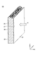
図1は、一実施形態に係る積層シートを示す断面図である。図1に示すように、積層シート2は、第1多孔質層10と、第2多孔質層20とを有する。第1多孔質層10は、積層シート2の耐燃性を向上するものであり、無機繊維および炭化繊維の少なくとも1つを複数本含む。一方、第2多孔質層20は、積層シート2の防音性を向上するものであり、複数本の有機繊維で形成される。
FIG. 1 is a sectional view showing a laminated sheet according to one embodiment. As shown in FIG. 1, the laminated sheet 2 has a first porous layer 10 and a second porous layer 20. The first porous layer 10 improves the fire resistance of the laminated sheet 2 and includes a plurality of at least one of inorganic fibers and carbonized fibers. On the other hand, the second porous layer 20 improves the soundproofing of the laminated sheet 2 and is formed of a plurality of organic fibers.
第1多孔質層10は、積層シート2の耐燃性を向上するものであるので、第2多孔質層20を基準として火源側に配置される。第2多孔質層20の温度を、第2多孔質層20を形成する有機繊維が熱分解する温度以下に抑制できる。第1多孔質層10の形態は、織布、不織布、およびフェルトなどのいずれでもよい。
る の で The first porous layer 10 is provided on the fire source side with respect to the second porous layer 20 because the first porous layer 10 improves the fire resistance of the laminated sheet 2. The temperature of the second porous layer 20 can be suppressed below the temperature at which the organic fibers forming the second porous layer 20 are thermally decomposed. The form of the first porous layer 10 may be any of woven cloth, nonwoven cloth, felt and the like.
一方、第2多孔質層20は、積層シート2の防音性を向上するものであるので、基本的には第1多孔質層10を基準として音源側に配置されるが、第1多孔質層10を基準として音源とは反対側に配置されてもよい。音波は、第1多孔質層10を通過できるからである。第2多孔質層20の形態は、織布、不織布、およびフェルトなどのいずれでもよい。
On the other hand, the second porous layer 20 is provided on the sound source side with reference to the first porous layer 10 because the second porous layer 20 improves the soundproofness of the laminated sheet 2. It may be arranged on the side opposite to the sound source with reference to 10. This is because sound waves can pass through the first porous layer 10. The form of the second porous layer 20 may be any of woven fabric, nonwoven fabric, felt, and the like.
第1多孔質層10と第2多孔質層20とは、別々に成形された後、結合されてよい。その結合には、例えば接着剤が用いられる。接着剤としては、熱可塑性樹脂などのホットメルト、または両面テープなどが用いられる。両面テープは、耐燃性を向上する目的で、基材を有しないものであってよい。接着剤は、音波が接着剤を通過しやすいように、例えば網状に形成されてよい。接着剤の代わりに、ニードルパンチが用いられてもよい。ニードルパンチ法は、第1多孔質層10と第2多孔質層20とを重ね合わせ、第1多孔質層10と第2多孔質層20との界面付近で繊維同士を絡み合わせる方法である。
The first porous layer 10 and the second porous layer 20 may be separately formed and then combined. For the connection, for example, an adhesive is used. As the adhesive, a hot melt such as a thermoplastic resin or a double-sided tape is used. The double-sided tape may have no base material for the purpose of improving the flame resistance. The adhesive may be formed, for example, in a net shape so that sound waves can easily pass through the adhesive. A needle punch may be used instead of the adhesive. The needle punching method is a method in which the first porous layer 10 and the second porous layer 20 are overlapped, and the fibers are entangled in the vicinity of the interface between the first porous layer 10 and the second porous layer 20.
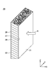
以下、積層シート2の全体構成、第1多孔質層10の構成、および第2多孔質層20の構成について、この順で説明する。なお、図2に示すように、積層シート2は、第2多孔質層20を基準として第1多孔質層10とは反対側に配置される第3多孔質層30を有してもよい。第3多孔質層30は、無機繊維および炭化繊維の少なくとも1つを複数本含む。第3多孔質層30の構成は、第1多孔質層10の構成と同様であるので、説明を省略する。
Hereinafter, the overall configuration of the laminated sheet 2, the configuration of the first porous layer 10, and the configuration of the second porous layer 20 will be described in this order. In addition, as shown in FIG. 2, the laminated sheet 2 may have a third porous layer 30 disposed on the opposite side of the first porous layer 10 with respect to the second porous layer 20. The third porous layer 30 includes a plurality of at least one of inorganic fibers and carbonized fibers. The configuration of the third porous layer 30 is the same as the configuration of the first porous layer 10, and a description thereof will be omitted.
積層シート2は、例えば、入射する音波を減衰させる防音材として用いられる。積層シート2は、入射する音波のエネルギーを熱のエネルギーに変換させることで、入射する音波を減衰させる。音波が積層シート2に入射すると、多孔質な積層シート2の内部で空気が振動するので、積層シート2を形成する繊維と空気との間に摩擦が生じ、音波のエネルギーが熱のエネルギーに変換される。
The laminated sheet 2 is used, for example, as a soundproof material for attenuating incident sound waves. The laminated sheet 2 attenuates the incident sound wave by converting the energy of the incident sound wave into the energy of heat. When sound waves enter the laminated sheet 2, the air vibrates inside the porous laminated sheet 2, so that friction occurs between the fibers forming the laminated sheet 2 and the air, and the energy of the sound waves is converted into heat energy. Is done.
積層シート2は、吸音材として用いられてもよいし、遮音材として用いられてもよい。吸音材は、音源から入射した音波の反射を抑制する目的で用いられる。遮音材は、音源から入射した音波の透過を抑制する目的で用いられる。積層シート2は、吸音材と遮音材の両方を兼ねてもよい。
Laminated sheet 2 may be used as a sound absorbing material or as a sound insulating material. The sound absorbing material is used for the purpose of suppressing reflection of sound waves incident from a sound source. The sound insulating material is used for the purpose of suppressing transmission of sound waves incident from a sound source. The laminated sheet 2 may serve as both a sound absorbing material and a sound insulating material.
積層シート2は、乗り物、建物、家庭用電気機器、大型電気機器などの騒音対策に用いられる。乗り物としては、例えば、自動車や電車などの車両や飛行機などが挙げられる。車両の騒音は、走行音、走行音がトンネルや遮音壁などで反射した反射音、車両に搭載される搭載機器(例えば空調機やエンジン)の作動音を含む。建物としては、例えば、工場や映画館、カラオケボックス、音楽ホールなどが挙げられる。家庭用電気機器としては、例えば、冷蔵庫や掃除機、エアコン室外機、家庭用蓄電池、温水洗浄便座などが挙げられる。大型電気機器としては、例えば業務用冷蔵庫などが挙げられる。
The laminated sheet 2 is used for noise control of vehicles, buildings, household electric appliances, large electric appliances and the like. Examples of the vehicle include a vehicle such as an automobile and a train, an airplane, and the like. The vehicle noise includes a running sound, a reflected sound of the running sound reflected on a tunnel, a sound insulating wall, or the like, and an operation sound of an on-board device (for example, an air conditioner or an engine) mounted on the vehicle. Examples of the building include a factory, a movie theater, a karaoke box, a music hall, and the like. Examples of the home electric appliance include a refrigerator, a vacuum cleaner, an outdoor unit of an air conditioner, a home storage battery, a hot water washing toilet seat, and the like. Examples of the large-sized electric device include a commercial refrigerator.
積層シート2の面密度は、例えば400g/m2以上1550g/m2以下である。積層シート2の面密度が1550g/m2以下であると、積層シート2の軽量性が良好である。一方、積層シート2の面密度が400g/m2以上であると、積層シート2の厚さD0が薄過ぎないので、音波が積層シート2の内部で吸収されやすい。従って、音波の透過を抑制でき、良好な遮音性を得られる。積層シート2の面密度は、好ましくは500g/m2以上1450g/m2以下である。
The areal density of the laminated sheet 2 is, for example, 400 g / m 2 or more 1550 g / m 2 or less. When the areal density of the laminated sheet 2 is 1550 g / m 2 or less, the lightweight property of the laminated sheet 2 is good. On the other hand, when the areal density of the laminated sheet 2 is 400 g / m 2 or more, the thickness D0 of the laminated sheet 2 is not too thin, so that sound waves are easily absorbed inside the laminated sheet 2. Therefore, transmission of sound waves can be suppressed, and good sound insulation can be obtained. The areal density of the laminated sheet 2 is preferably 500 g / m 2 or more 1450 g / m 2 or less.
積層シート2の厚さD0は、例えば1mm以上100mm以下である。積層シート2の厚さD0が100mm以下であると、積層シート2の軽量性が良好である。また、積層シート2の厚さD0が100mm以下であると、積層シート2の厚さD0が厚過ぎないので、音波が積層シート2に入射やすい。従って、音波の反射を抑制でき、良好な吸音性を得られる。一方、積層シート2の厚さD0が1mm以上であると、積層シート2の厚さD0が薄過ぎないので、音波が積層シート2の内部で吸収されやすい。従って、音波の透過を抑制でき、良好な遮音性を得られる。積層シート2の厚さD0は、好ましくは5mm以上80mm以下である。
厚 The thickness D0 of the laminated sheet 2 is, for example, 1 mm or more and 100 mm or less. When the thickness D0 of the laminated sheet 2 is 100 mm or less, the lightweight property of the laminated sheet 2 is good. When the thickness D0 of the laminated sheet 2 is 100 mm or less, the thickness D0 of the laminated sheet 2 is not too thick, so that sound waves are easily incident on the laminated sheet 2. Therefore, reflection of sound waves can be suppressed, and good sound absorbing properties can be obtained. On the other hand, if the thickness D0 of the laminated sheet 2 is 1 mm or more, the thickness D0 of the laminated sheet 2 is not too thin, so that sound waves are easily absorbed inside the laminated sheet 2. Therefore, transmission of sound waves can be suppressed, and good sound insulation can be obtained. The thickness D0 of the laminated sheet 2 is preferably 5 mm or more and 80 mm or less.
積層シート2の減衰定数は、例えば10Neper/m以上30Neper/m以下である。積層シート2の減衰定数が10Neper/m以上であると、積層シート2に入射した音波が積層シート2の内部で吸収されやすい。従って、音波の透過を抑制でき、良好な遮音性を得られる。一方、積層シート2の減衰定数が30Neper以下であると、積層シート2のかさ密度が高過ぎないので、音波が積層シート2に入射しやすい。従って、音波の反射を抑制でき、良好な吸音性を得られる。積層シート2の減衰定数は、好ましくは12Neper/m以上25Neper/m以下である。
減 衰 The damping constant of the laminated sheet 2 is, for example, 10 Neper / m or more and 30 Neper / m or less. When the attenuation constant of the laminated sheet 2 is 10 Neper / m or more, sound waves incident on the laminated sheet 2 are easily absorbed inside the laminated sheet 2. Therefore, transmission of sound waves can be suppressed, and good sound insulation can be obtained. On the other hand, when the attenuation constant of the laminated sheet 2 is 30 Neper or less, the acoustic wave is likely to enter the laminated sheet 2 because the bulk density of the laminated sheet 2 is not too high. Therefore, reflection of sound waves can be suppressed, and good sound absorbing properties can be obtained. The damping constant of the laminated sheet 2 is preferably from 12 Neper / m to 25 Neper / m.
積層シート2の特性インピーダンスは、例えば300N・s/m3以上1400N・s/m3以下である。特性インピーダンスは音波の伝わりにくさを表すものである。特性インピーダンスが大きいほど、音波の伝播が妨げられやすく、音波が反射されやすいため、吸音性が低下する。積層シート2の特性インピーダンスが300N・s/m3以上であると、積層シート2に入射した音波が積層シート2の内部で吸収されやすい。従って、音波の透過を抑制でき、良好な遮音性を得られる。一方、積層シート2の特性インピーダンスが1400N・s/m3以下であると、音波が積層シート2に入射しやすい。従って、音波の反射を抑制でき、良好な吸音性を得られる。
The characteristic impedance of the laminated sheet 2 is, for example, 300 N · s / m 3 or more and 1400 N · s / m 3 or less. The characteristic impedance indicates the difficulty in transmitting sound waves. As the characteristic impedance increases, the propagation of the sound wave is more likely to be hindered, and the sound wave is more likely to be reflected. When the characteristic impedance of the laminated sheet 2 is 300 N · s / m 3 or more, sound waves incident on the laminated sheet 2 are easily absorbed inside the laminated sheet 2. Therefore, transmission of sound waves can be suppressed, and good sound insulation can be obtained. On the other hand, when the characteristic impedance of the laminated sheet 2 is 1400 N · s / m 3 or less, sound waves are likely to enter the laminated sheet 2. Therefore, reflection of sound waves can be suppressed, and good sound absorbing properties can be obtained.
第1多孔質層10は、積層シート2の耐燃性を向上するものであり、無機繊維および炭化繊維の少なくとも1つを複数本含む。無機繊維としては、例えば、ガラス繊維、セラミック繊維、金属繊維、炭素繊維が挙げられる。セミラック繊維は、例えばシリカ繊維である。金属繊維は、例えばアルミニウム繊維、または銅繊維である。炭素繊維は、ポリアクリロニトリル繊維を全体的に炭化したものである。一方、炭化繊維は、ポリアクリロニトリル繊維を部分的に炭化したものである。たとえば、ポリアクリロニトリル繊維を空気雰囲気下で200℃以上300℃以下の温度で加熱することにより炭化繊維が得られ、炭化繊維を不活性ガス雰囲気下で1200℃以上1400℃以下の温度で加熱することにより炭素繊維が得られる。第1多孔質層10は、複数種類の無機繊維を含んでもよい。また、第1多孔質層10は、無機繊維と炭化繊維とを両方含んでもよい。
The first porous layer 10 improves the fire resistance of the laminated sheet 2 and includes a plurality of at least one of inorganic fibers and carbonized fibers. Examples of the inorganic fibers include glass fibers, ceramic fibers, metal fibers, and carbon fibers. The semi-lac fiber is, for example, a silica fiber. The metal fiber is, for example, an aluminum fiber or a copper fiber. The carbon fiber is obtained by entirely carbonizing polyacrylonitrile fiber. On the other hand, the carbonized fiber is obtained by partially carbonizing polyacrylonitrile fiber. For example, carbonized fibers are obtained by heating polyacrylonitrile fibers at a temperature of 200 ° C. or more and 300 ° C. or less in an air atmosphere, and heating the carbonized fibers at a temperature of 1200 ° C. or more and 1400 ° C. or less under an inert gas atmosphere. Gives a carbon fiber. The first porous layer 10 may include a plurality of types of inorganic fibers. Further, the first porous layer 10 may include both inorganic fibers and carbonized fibers.
第1多孔質層10の厚さD1は、例えば0.5mm以上10mm以下である。第1多孔質層10の厚さD1が0.5mm以上であると、火源の熱が第1多孔質層10を介して第2多孔質層20に伝達することを抑制できる。従って、第2多孔質層20の温度を、第2多孔質層20を形成する有機繊維が熱分解する温度以下に抑制できる。一方、第1多孔質層10の厚さD1が10mm以下であると、積層シート2の面密度が大き過ぎないので、軽量性が良好であり、また、防音性が良好である。第1多孔質層10の厚さD1は、好ましくは0.7mm以上7mm以下であり、より好ましくは0.9mm以上5mm以下である。
厚 The thickness D1 of the first porous layer 10 is, for example, 0.5 mm or more and 10 mm or less. When the thickness D1 of the first porous layer 10 is 0.5 mm or more, it is possible to suppress the heat of the fire source from being transmitted to the second porous layer 20 via the first porous layer 10. Therefore, the temperature of the second porous layer 20 can be suppressed to a temperature at which the organic fibers forming the second porous layer 20 are thermally decomposed. On the other hand, when the thickness D1 of the first porous layer 10 is 10 mm or less, the surface density of the laminated sheet 2 is not too large, so that the lightness is good and the soundproofing is good. The thickness D1 of the first porous layer 10 is preferably 0.7 mm or more and 7 mm or less, and more preferably 0.9 mm or more and 5 mm or less.
第1多孔質層10の熱貫流率は、例えば5.0W/m2・K以上1.0×103W/m2・K以下である。第1多孔質層10の熱貫流率T1は、「T1=λ1/D1」の式で表すことができる。ここで、λ1は第1多孔質層10の熱伝導率であり、D1は第1多孔質層10の厚さである。第1多孔質層10の熱貫流率が1.0×103W/m2・K以下であると、火源の熱が第1多孔質層10を介して第2多孔質層20に伝達することを抑制できる。従って、図12に示す燃焼試験を実施したときに、変形率を50%以下に制限できる。変形率とは、第2多孔質層20の火源とは反対側の主表面の全面積を100%としたときの、主表面の熱によって変形する部分の面積の比率である。一方、第1多孔質層10の熱貫流率が5.0W/m2・K以上であると、第1多孔質層10の厚さD1が厚過ぎないので、積層シート2の軽量性が良好である。第1多孔質層10の熱貫流率は、好ましくは6.7W/m2・K以上7.7×102W/m2・K以下であり、より好ましくは1.0×101W/m2・K以上5.9×102W/m2・K以下である。
Heat transmission coefficient of the first porous layer 10 is, for example, less 5.0W / m 2 · K or more 1.0 × 10 3 W / m 2 · K. The heat transmission coefficient T1 of the first porous layer 10 can be represented by the equation “T1 = λ1 / D1”. Here, λ1 is the thermal conductivity of the first porous layer 10, and D1 is the thickness of the first porous layer 10. When the heat transmission coefficient of the first porous layer 10 is 1.0 × 10 3 W / m 2 · K or less, the heat of the fire source is transmitted to the second porous layer 20 via the first porous layer 10. Can be suppressed. Therefore, when the combustion test shown in FIG. 12 is performed, the deformation rate can be limited to 50% or less. The deformation rate is the ratio of the area of the main surface that is deformed by heat when the total area of the main surface of the second porous layer 20 opposite to the fire source is defined as 100%. On the other hand, when the heat transmission coefficient of the first porous layer 10 is 5.0 W / m 2 · K or more, the thickness D1 of the first porous layer 10 is not too thick, so that the light weight of the laminated sheet 2 is good. It is. Heat transmission coefficient of the first porous layer 10 is preferably not more than 6.7W / m 2 · K or more 7.7 × 10 2 W / m 2 · K, more preferably 1.0 × 10 1 W / m 2 · K or more and 5.9 × 10 2 W / m 2 · K or less.
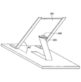
図3は、一実施形態に係る第2多孔質層を示す斜視図である。図4は、一実施形態に係る第2多孔質層を示す断面写真である。図3および図4において、X軸方向、Y軸方向、Z軸方向は互いに垂直な方向である。X軸方向は第2多孔質層の厚さ方向である。Y軸方向およびZ軸方向は第2多孔質層の面内方向である。Z軸方向が複数の不織布層の並ぶ方向である。
FIG. 3 is a perspective view showing a second porous layer according to one embodiment. FIG. 4 is a cross-sectional photograph showing a second porous layer according to one embodiment. 3 and 4, the X-axis direction, the Y-axis direction, and the Z-axis direction are directions perpendicular to each other. The X-axis direction is the thickness direction of the second porous layer. The Y-axis direction and the Z-axis direction are in-plane directions of the second porous layer. The Z-axis direction is the direction in which the plurality of nonwoven fabric layers are arranged.
図3において、矢印Aは、第2多孔質層20に対する音波の入射方向を表す。尚、図3では、音波は、第2多孔質層20の主表面21に対し垂直に入射しているが、斜めに入射してもよい。また、音波は、第2多孔質層20の両側から入射してもよく、2つの主表面21、22の両方に入射してもよい。
矢 印 In FIG. 3, the arrow A indicates the incident direction of the sound wave on the second porous layer 20. In FIG. 3, the sound wave is incident perpendicularly to the main surface 21 of the second porous layer 20, but may be incident obliquely. In addition, the sound wave may be incident from both sides of the second porous layer 20 or may be incident on both of the two main surfaces 21 and 22.
第2多孔質層20は、入射する音波を減衰させるものである。第2多孔質層20は、入射する音波のエネルギーを熱のエネルギーに変換させることで、入射する音波を減衰させる。音波が第2多孔質層20に入射すると、第2多孔質層20の内部で空気が振動するので、第2多孔質層20を形成する有機繊維と空気との間に摩擦が生じ、音波のエネルギーが熱のエネルギーに変換される。
{Circle around (2)} The second porous layer 20 attenuates incident sound waves. The second porous layer 20 attenuates the incident sound wave by converting the energy of the incident sound wave into the energy of heat. When a sound wave enters the second porous layer 20, the air vibrates inside the second porous layer 20, so that friction occurs between the organic fibers forming the second porous layer 20 and the air, and the sound wave Energy is converted to heat energy.
第2多孔質層20は、吸音材として用いられてもよいし、遮音材として用いられてもよい。吸音材は、音源から入射した音波の反射を抑制する目的で用いられる。遮音材は、音源から入射した音波の透過を抑制する目的で用いられる。第2多孔質層20は、吸音材と遮音材の両方を兼ねてもよい。
The second porous layer 20 may be used as a sound absorbing material or may be used as a sound insulating material. The sound absorbing material is used for the purpose of suppressing reflection of sound waves incident from a sound source. The sound insulating material is used for the purpose of suppressing transmission of sound waves incident from a sound source. The second porous layer 20 may serve as both a sound absorbing material and a sound insulating material.
第2多孔質層20は、複数本の有機繊維で形成される。有機繊維としては、特に限定されないが、例えば、ポリエステル繊維、ポリオレフィン系樹脂繊維、ポリアミド繊維、アクリル繊維、ナイロン繊維等を使用できる。これらの中でも、軽量化の観点から、ポリオレフィン系樹脂繊維が特に好ましい。第2多孔質層20は、一種類の有機繊維で形成されてもよいし、複数種類の有機繊維で形成されてもよい。
The second porous layer 20 is formed of a plurality of organic fibers. The organic fiber is not particularly limited, and for example, polyester fiber, polyolefin-based resin fiber, polyamide fiber, acrylic fiber, nylon fiber, and the like can be used. Among these, polyolefin-based resin fibers are particularly preferable from the viewpoint of weight reduction. The second porous layer 20 may be formed of one type of organic fiber, or may be formed of a plurality of types of organic fibers.
なお、第2多孔質層20は、有機繊維の他に、添加剤を含んでもよい。添加剤は、例えば難燃剤である。難燃剤は、有機系難燃剤でもよいし、無機系難燃剤でもよい。有機系難燃剤としては、例えば、リン系化合物、ハロゲン系化合物、窒素系化合物、シリコーン系化合物、ホウ素系化合などが挙げられる。無機系難燃剤としては、金属水和物、三酸化アンチモン、無機リンなどが挙げられる。添加剤は、撥水剤でもよい。撥水剤としては、例えば、フッ素系化合物などが挙げられる。その他の添加剤としては、耐候安定剤、酸化防止剤、着色剤などが挙げられる。添加剤は、有機繊維にコーティングされてもよい。
The second porous layer 20 may include an additive in addition to the organic fiber. The additive is, for example, a flame retardant. The flame retardant may be an organic flame retardant or an inorganic flame retardant. Examples of the organic flame retardant include a phosphorus compound, a halogen compound, a nitrogen compound, a silicone compound, and a boron compound. Examples of the inorganic flame retardant include metal hydrate, antimony trioxide, and inorganic phosphorus. The additive may be a water repellent. Examples of the water repellent include a fluorine-based compound. Other additives include a weather resistance stabilizer, an antioxidant, a coloring agent, and the like. Additives may be coated on the organic fibers.
第2多孔質層20は、例えば平均繊維径が0.5μm以上14μm以下の有機繊維で形成される。第2多孔質層20の平均繊維径が0.5μm以上であると、第2多孔質層20の製造が容易であり、また、第2多孔質層20の強度が十分に得られる。一方、第2多孔質層20の平均繊維径が14μm以下であると、単位体積当たりの有機繊維の表面積が広いため、有機繊維と空気との間で摩擦が生じやすく、音波を効率的に減衰することができる。第2多孔質層20の平均繊維径は、好ましくは1μm以上14μm以下であり、より好ましくは1.5μm以上10μm以下である。
The second porous layer 20 is formed of, for example, organic fibers having an average fiber diameter of 0.5 μm or more and 14 μm or less. When the average fiber diameter of the second porous layer 20 is 0.5 μm or more, the production of the second porous layer 20 is easy, and the strength of the second porous layer 20 is sufficiently obtained. On the other hand, when the average fiber diameter of the second porous layer 20 is 14 μm or less, the surface area of the organic fibers per unit volume is large, so that friction is easily generated between the organic fibers and the air, and the sound waves are efficiently attenuated. can do. The average fiber diameter of the second porous layer 20 is preferably 1 μm or more and 14 μm or less, more preferably 1.5 μm or more and 10 μm or less.
第2多孔質層20は、平均繊維径が0.5μm以上14μm以下である有機繊維などの固体と、有機繊維間に形成される空隙とで構成される。本発明者は、第2多孔質層20の防音性を向上するため、従来着目されていなかった固体占有率Sに着目した。
The second porous layer 20 is composed of a solid such as an organic fiber having an average fiber diameter of 0.5 μm or more and 14 μm or less, and a void formed between the organic fibers. The present inventor focused on the solid occupancy S, which has not been focused on in the past, in order to improve the soundproofing of the second porous layer 20.
固体占有率Sとは、第2多孔質層20の単位体積に占める固体と空隙の全体積を100%としたときの、固体の割合のことである。つまり、固体占有率Sは、第2多孔質層20のかさ密度(BD)を固体の真密度(TD)で除した値(BD/TD)に100を乗じた値(BD/TD×100)である。固体占有率Sは、100から空隙率を差し引いたものと等しい。
The solid occupancy S is a ratio of the solid when the total volume of the solid and the voids in the unit volume of the second porous layer 20 is 100%. That is, the solid occupancy S is a value (BD / TD × 100) obtained by multiplying the value (BD / TD) obtained by dividing the bulk density (BD) of the second porous layer 20 by the true density (TD) of the solid by 100 (BD / TD × 100). It is. The solids occupancy S is equal to 100 minus the porosity.
固体占有率Sが大きいほど、平均繊維径が0.5μm以上14μm以下である有機繊維と空気との接触面積が大きく、有機繊維と空気との摩擦によって音波のエネルギーを熱のエネルギーに変換する効率が向上するため、防音性が向上する。一方、固体占有率Sが小さいほど、密度が小さく、軽量化が図れる。
The larger the solid occupancy S, the larger the contact area between the organic fiber having an average fiber diameter of 0.5 μm or more and 14 μm or less and air, and the efficiency of converting sound energy into heat energy by friction between the organic fiber and air. Is improved, so that soundproofing is improved. On the other hand, the smaller the solid occupancy S, the lower the density and the weight can be reduced.
本実施形態では、固体占有率Sは、1.0%以上8.0%以下である。固体占有率Sが1.0%以上であると、平均繊維径が0.5μm以上14μm以下である有機繊維と空気との摩擦によって音波が減衰されやすく、減衰定数10Neper/m以上を達成することができる。また、固体占有率Sが8.0%以下であると、軽量化を図ることができる。固体占有率Sは、好ましくは1.3%以上7.0%以下であり、より好ましくは1.4%以上6.0%以下である。
で は In the present embodiment, the solid occupancy S is 1.0% or more and 8.0% or less. When the solid occupation ratio S is 1.0% or more, sound waves are easily attenuated by friction between the organic fibers having an average fiber diameter of 0.5 μm or more and 14 μm or less and air, and achieve an attenuation constant of 10 Neper / m or more. Can be. When the solid occupation ratio S is 8.0% or less, the weight can be reduced. The solid occupation ratio S is preferably 1.3% or more and 7.0% or less, and more preferably 1.4% or more and 6.0% or less.
固体は、主に、平均繊維径が0.5μm以上14μm以下の有機繊維を含む。固体は、繊維径が10μm以上30μm以下の有機繊維を含んでもよい。平均繊維径が0.5μm以上14μm以下であればよい。また、固体は、第2多孔質層20の形状保持のため、低融点の有機繊維や粘着性の有機繊維を含んでもよい。さらに、固体は、上記の添加剤を、防音性を損なわない範囲で含んでもよい。
The solid mainly contains organic fibers having an average fiber diameter of 0.5 μm or more and 14 μm or less. The solid may include organic fibers having a fiber diameter of 10 μm or more and 30 μm or less. The average fiber diameter may be 0.5 μm or more and 14 μm or less. Further, the solid may include low-melting organic fibers or sticky organic fibers for maintaining the shape of the second porous layer 20. Further, the solid may contain the above-mentioned additive in a range that does not impair the soundproofing property.
第2多孔質層20の厚さD2は、例えば1mm以上100mm以下である。第2多孔質層20の厚さD2が1mm以上であると、第2多孔質層20の形状を維持できる。一方、第2多孔質層20の厚さD2が100mm以下であると、第2多孔質層20の軽量化を図ることができる。
厚 The thickness D2 of the second porous layer 20 is, for example, 1 mm or more and 100 mm or less. When the thickness D2 of the second porous layer 20 is 1 mm or more, the shape of the second porous layer 20 can be maintained. On the other hand, when the thickness D2 of the second porous layer 20 is 100 mm or less, the weight of the second porous layer 20 can be reduced.
第2多孔質層20は、互いに対向する2つの主表面21、22の間に、予め定められた面内方向(図3および図4ではZ軸方向)に剥離可能に連続的に並ぶ複数の不織布層26を有する。複数の不織布層26のそれぞれは、予め定められた面内方向(図3および図4ではZ軸方向)から見たときに複数の有機繊維が絡まり合うものである。隣り合う不織布層26は、互いの界面で簡単に剥離できる。
The second porous layer 20 is formed of a plurality of strips that are continuously arranged between two opposing main surfaces 21 and 22 in a predetermined in-plane direction (the Z-axis direction in FIGS. 3 and 4) so as to be peelable. It has a nonwoven fabric layer 26. Each of the plurality of nonwoven fabric layers 26 includes a plurality of organic fibers tangled when viewed from a predetermined in-plane direction (the Z-axis direction in FIGS. 3 and 4). Adjacent nonwoven fabric layers 26 can be easily peeled off at the interface between each other.
隣り合う不織布層26の剥離強度を高めるため、不織布層26同士を連結する捲縮繊維が挿入されてもよいが、本実施形態では挿入されない。捲縮繊維は、繊維径が太く、比表面積が小さいことから、空気の粘性抵抗によるエネルギー減衰が得られ難く、減衰定数が小さくなるためである。
捲 In order to increase the peel strength of the adjacent nonwoven fabric layers 26, crimped fibers connecting the nonwoven fabric layers 26 may be inserted, but are not inserted in the present embodiment. This is because the crimped fiber has a large fiber diameter and a small specific surface area, so that it is difficult to obtain energy attenuation due to viscous resistance of air, and the attenuation constant becomes small.
ところで、音波は、空気の密度の振動が伝播するものであり、縦波(疎密波)である。有機繊維と有機繊維の間に形成される空隙において空気の密度が変化すると、空気の密度変化による圧力変化が有機繊維に生じる。1本の有機繊維の任意の部位で同時に同じ圧力変化が生じる場合、有機繊維が共振する。有機繊維が共振するのは、例えば有機繊維が音波の伝播方向に対し垂直に配置される場合である。
音波 By the way, the sound wave is a wave in which the vibration of the density of the air propagates, and is a longitudinal wave (compression wave). When the density of air changes in a gap formed between organic fibers, a change in pressure due to the change in density of air occurs in the organic fibers. When the same pressure change occurs simultaneously in any part of one organic fiber, the organic fiber resonates. The organic fibers resonate, for example, when the organic fibers are arranged perpendicular to the propagation direction of the sound wave.
共振する有機繊維の本数が多いほど、音波の伝播が妨げられやすく、音波が反射されやすいため、吸音性が低下する。音波の伝わりにくさは、特性インピーダンスで評価できる。特性インピーダンスが大きいほど、音波の伝播が妨げられやすく、音波が反射されやすいため、吸音性が低下する。
(4) As the number of resonating organic fibers increases, the propagation of sound waves is more likely to be hindered and the sound waves are more likely to be reflected. The difficulty in transmitting sound waves can be evaluated by characteristic impedance. As the characteristic impedance increases, the propagation of the sound wave is more likely to be hindered, and the sound wave is more likely to be reflected.
また、共振する有機繊維の本数が多いほど、音波の伝播が妨げられやすく、空気と有機繊維との摩擦による音波の減衰が妨げられる。
Further, as the number of resonating organic fibers increases, the propagation of sound waves is more likely to be hindered, and the attenuation of sound waves due to friction between air and the organic fibers is hindered.
本実施形態によれば、上述の如く、複数の不織布層26がZ軸方向に剥離可能に連続的に並ぶ。そのため、例えば図3に矢印Aで示すように音波がX軸方向に入射するとき、各不織布層26において音波の伝播方向に対して垂直な有機繊維の本数を低減でき、各不織布層26において有機繊維の共振を抑制できる。その結果、かさ密度が同じ横配向品つまり固体占有率Sが同じ横配向品に比べて、特性インピーダンスを下げることができる。詳しくは後述するが、複数の不織布層26が面内方向(図3および図4ではZ軸方向)に連続的に並ぶ構造を縦配向と呼び、複数の不織布層26Aが厚さ方向(図9および図10ではZ軸方向)に連続的に並ぶ構造を横配向とも呼ぶ。
According to the present embodiment, as described above, the plurality of nonwoven fabric layers 26 are continuously arranged so as to be peelable in the Z-axis direction. Therefore, for example, when a sound wave is incident in the X-axis direction as shown by an arrow A in FIG. 3, the number of organic fibers perpendicular to the sound wave propagation direction in each nonwoven fabric layer 26 can be reduced. Fiber resonance can be suppressed. As a result, the characteristic impedance can be reduced as compared with a horizontally oriented product having the same bulk density, that is, a horizontally oriented product having the same solid occupancy S. As will be described in detail later, a structure in which the plurality of nonwoven fabric layers 26 are continuously arranged in the in-plane direction (the Z-axis direction in FIGS. 3 and 4) is called a vertical orientation, and the plurality of nonwoven fabric layers 26A are arranged in the thickness direction (FIG. 9). In FIG. 10 and in FIG. 10, a structure continuously arranged in the Z-axis direction) is also referred to as a lateral orientation.
尚、特性インピーダンス(つまり、音波の伝わりにくさ)を下げるだけであれば、固体占有率Sを1.0%未満にする(つまり、空隙率を99.0%以上にする)ことも考えられる。この場合、減衰定数が小さ過ぎて、遮音性が悪化してしまうため、本実施形態では固体占有率Sは1.0%以上としてある。固体占有率Sを1.0%以上とすると共に、縦配向の構造を採用することにより、遮音性と吸音性を両立できる。遮音材と吸音材の両方の機能が要求される用途で、特に有効である。
If only the characteristic impedance (that is, the difficulty in transmitting sound waves) is reduced, the solid occupancy S may be reduced to less than 1.0% (that is, the porosity may be increased to 99.0% or more). . In this case, the damping constant is too small and the sound insulation deteriorates. Therefore, in this embodiment, the solid occupancy S is set to 1.0% or more. By setting the solid occupancy S to 1.0% or more and employing a vertically oriented structure, both sound insulation and sound absorption can be achieved. This is particularly effective in applications where both functions of a sound insulating material and a sound absorbing material are required.
不織布層26は、図3および図4に示すようにY軸方向視でC字状に形成される。尚、不織布層26のY軸方向視での形状は、本実施形態ではC字状であるが、特に限定されず、例えば、図5に示すように波線状でもよいし、図6に示すように直線状でもよい。不織布層26のY軸方向視での形状は、図6ではZ軸方向に対し斜めの直線であるが、Z軸方向に対し垂直な直線であってもよい。
The nonwoven fabric layer 26 is formed in a C shape as viewed in the Y-axis direction as shown in FIGS. The shape of the nonwoven fabric layer 26 as viewed in the Y-axis direction is C-shaped in the present embodiment, but is not particularly limited. For example, the shape may be a wavy line as shown in FIG. 5 or as shown in FIG. It may be linear. The shape of the nonwoven fabric layer 26 as viewed in the Y-axis direction is a straight line oblique to the Z-axis direction in FIG. 6, but may be a straight line perpendicular to the Z-axis direction.
第2多孔質層20は、互いに対向する2つの主表面21、22のうち、一方の主表面21にスキン層27を有し、他方の主表面22にスキン層28を有する。2つのスキン層27、28は、それぞれ、厚さ方向(図3および図4ではX軸方向)から見たときに、複数の有機繊維が絡まり合うもの(つまり、不織布)である。
The second porous layer 20 has a skin layer 27 on one main surface 21 and a skin layer 28 on the other main surface 22 of the two main surfaces 21 and 22 facing each other. Each of the two skin layers 27 and 28 is one in which a plurality of organic fibers are entangled (that is, a nonwoven fabric) when viewed from the thickness direction (the X-axis direction in FIGS. 3 and 4).
2つのスキン層27、28の間には複数の不織布層26が設けられ、各不織布層26は2つのスキン層27、28と連続的に形成される。各スキン層27、28の厚さは薄く、隣り合う不織布層26が互いの界面で剥離されるとき、その界面の延長面で各スキン層27、28が分断される。
複数 A plurality of nonwoven fabric layers 26 are provided between the two skin layers 27 and 28, and each nonwoven fabric layer 26 is formed continuously with the two skin layers 27 and 28. The thickness of each of the skin layers 27 and 28 is thin, and when the adjacent nonwoven fabric layers 26 are separated at the interface between them, the skin layers 27 and 28 are separated from each other on the extended surface of the interface.
スキン層27の厚さD4およびスキン層28の厚さD5は、それぞれ、0.01mm以上5mm以下である。厚さD4および厚さD5がそれぞれ0.01mm以上であると、隣り合う不織布層26の界面での意図しない剥離を抑制でき、形状を維持できる。一方、厚さD4および厚さD5がそれぞれ5mm以下であると、スキン層27による音波の反射を抑制でき、不織布層26における音波の減衰を促進できる。厚さD4および厚さD5は、それぞれ、好ましくは0.3mm以上4mm以下、より好ましくは0.6mm以上3mm以下である。
The thickness D4 of the skin layer 27 and the thickness D5 of the skin layer 28 are each 0.01 mm or more and 5 mm or less. When the thickness D4 and the thickness D5 are each 0.01 mm or more, unintended peeling at the interface between the adjacent nonwoven fabric layers 26 can be suppressed, and the shape can be maintained. On the other hand, when the thickness D4 and the thickness D5 are each 5 mm or less, the reflection of the sound wave by the skin layer 27 can be suppressed, and the attenuation of the sound wave in the nonwoven fabric layer 26 can be promoted. Each of the thickness D4 and the thickness D5 is preferably 0.3 mm or more and 4 mm or less, and more preferably 0.6 mm or more and 3 mm or less.
第2多孔質層20の製造方法としては、特に限定されないが、溶融紡糸法が好適であり、メルトブローン法が特に好適である。メルトブローン法は、溶融した熱可塑性樹脂をノズルから吹き出して高温、高速の気流で繊維状に引き伸ばし、コレクタ上で有機繊維を紡糸する方法である。熱可塑性樹脂は、ポリオレフィン系樹脂、ポリエステル系樹脂、ポリアミド系樹脂のいずれかの少なくとも1種類を含む。
製造 The method for producing the second porous layer 20 is not particularly limited, but a melt spinning method is preferable, and a melt blown method is particularly preferable. The melt blown method is a method in which a molten thermoplastic resin is blown out from a nozzle, stretched into a fibrous shape by a high-temperature, high-speed airflow, and spun organic fibers on a collector. The thermoplastic resin contains at least one of a polyolefin resin, a polyester resin, and a polyamide resin.
尚、第2多孔質層20の製造方法は、メルトブローン法に限定されず、例えば電界紡糸法などでもよい。メルトブローン法や電界紡糸法によれば、不織布が得られる。
The method for manufacturing the second porous layer 20 is not limited to the melt blown method, but may be, for example, an electrospinning method. According to the melt blown method or the electrospinning method, a nonwoven fabric can be obtained.
図7は、一実施形態に係る第2多孔質層の製造方法を示す図である。図7におけるX軸方向、Y軸方向およびZ軸方向は、図3および図4におけるX軸方向、Y軸方向およびZ軸方向と同じ意味である。図7において、矢印Bは、第2多孔質層20の搬送方向(Z軸方向)である。第2多孔質層20を製造する製造装置100は、図7に示すように、ダイス110と、2つのコレクタ120とを有する。
FIG. 7 is a diagram illustrating a method for manufacturing a second porous layer according to one embodiment. The X-axis direction, the Y-axis direction, and the Z-axis direction in FIG. 7 have the same meaning as the X-axis direction, the Y-axis direction, and the Z-axis direction in FIGS. In FIG. 7, an arrow B is a transport direction (Z-axis direction) of the second porous layer 20. The manufacturing apparatus 100 for manufacturing the second porous layer 20 has a die 110 and two collectors 120, as shown in FIG.
ダイス110は、溶融樹脂を吐出する樹脂ノズル111と、空気などのガスを吐出するガスノズル112とを有する。樹脂ノズル111は、例えば鉛直方向下方に向けて溶融樹脂を吐出する。ガスノズル112は、樹脂ノズル111のX軸方向両側に設けられ、それぞれ、樹脂ノズル111から吐出される溶融樹脂の流れと交わるように、斜め下方に高温のガスを吐出する。樹脂ノズル111の吐出口、およびガスノズル112の吐出口は、ダイス110の下面に、Y軸方向に間隔をおいて複数設けられる。尚、樹脂ノズル111の吐出方向は、本実施形態ではZ軸方向(より詳細には鉛直下方)であるが、Z軸方向に対し傾斜した方向であってもよい。
The die 110 has a resin nozzle 111 for discharging a molten resin and a gas nozzle 112 for discharging a gas such as air. The resin nozzle 111 discharges the molten resin, for example, vertically downward. The gas nozzles 112 are provided on both sides of the resin nozzle 111 in the X-axis direction, and each discharge a high-temperature gas obliquely downward so as to intersect with the flow of the molten resin discharged from the resin nozzle 111. A plurality of outlets of the resin nozzle 111 and outlets of the gas nozzle 112 are provided on the lower surface of the die 110 at intervals in the Y-axis direction. In this embodiment, the ejection direction of the resin nozzle 111 is the Z-axis direction (more specifically, vertically downward), but may be a direction inclined with respect to the Z-axis direction.
2つのコレクタ120の互いに対向する面は、平行とされ、それぞれX軸方向に対し垂直とされる。2つのコレクタ120の互いに対向する面の間に、第2多孔質層20の搬送経路が形成される。第2多孔質層20は、無端ベルト123と共にZ軸方向(より詳細には鉛直下方)に搬送され、2つのコレクタ120の間を通過した後、湾曲され、水平に搬送される。その結果、第2多孔質層20の厚さD2(図3参照)は、自重などにより2つのコレクタ120の間隔Wよりも小さくなる。尚、2つのコレクタ120の間隔Wは、本実施形態では図7に示すように一定であるが、搬送方向上流側から搬送方向下流側に向うほど、狭くなってもよいし、広くなってもよい。
The surfaces of the two collectors 120 facing each other are made parallel and perpendicular to the X-axis direction. A transport path for the second porous layer 20 is formed between the surfaces of the two collectors 120 facing each other. The second porous layer 20 is transported together with the endless belt 123 in the Z-axis direction (more specifically, vertically downward), passes between the two collectors 120, is curved, and is transported horizontally. As a result, the thickness D2 (see FIG. 3) of the second porous layer 20 becomes smaller than the distance W between the two collectors 120 due to its own weight or the like. In this embodiment, the interval W between the two collectors 120 is constant as shown in FIG. 7, but may be narrower or wider from the upstream side in the transport direction to the downstream side in the transport direction. Good.
各コレクタ120は、例えば、第1プーリー121、第2プーリー122、および第1プーリー121と第2プーリー122との間に架け渡される無端ベルト123を有する。第1プーリー121および第2プーリー122のそれぞれの回転軸の軸方向は、Y軸方向とされる。第1プーリー121および第2プーリー122のうち少なくとも1つは、回転モータなどの駆動源によって回転させられる駆動プーリーである。駆動プーリーを連続的に回転させることにより、無端ベルト123と共に第2多孔質層20が連続的に搬送される。
Each collector 120 has, for example, a first pulley 121, a second pulley 122, and an endless belt 123 bridged between the first pulley 121 and the second pulley 122. The axial direction of each rotation shaft of the first pulley 121 and the second pulley 122 is the Y-axis direction. At least one of the first pulley 121 and the second pulley 122 is a drive pulley that is rotated by a drive source such as a rotary motor. By continuously rotating the driving pulley, the second porous layer 20 is continuously transported together with the endless belt 123.
図8は、図7に示す2つのコレクタ間に形成される有機繊維層の一例を示す図である。樹脂ノズル111から吐出された溶融樹脂は、ガスノズル112から吐出された高速の気流で繊維状に引き伸ばされ、有機繊維層29を形成する。有機繊維層29は、Z軸方向視で、複数の有機繊維が絡まり合う不織布である。
FIG. 8 is a diagram showing an example of the organic fiber layer formed between the two collectors shown in FIG. The molten resin discharged from the resin nozzle 111 is stretched into a fibrous shape by the high-speed airflow discharged from the gas nozzle 112 to form the organic fiber layer 29. The organic fiber layer 29 is a nonwoven fabric in which a plurality of organic fibers are entangled when viewed in the Z-axis direction.
有機繊維層29は、Z軸方向視で、X軸方向に間隔をおいて設けられる2つのコレクタ120間に架け渡される。有機繊維層29のX軸方向端部は、図7に示すように無端ベルト123の上端部付近に付着する。無端ベルト123の上端部は、第1プーリー121の外周に抱き付いており、第1プーリー121の回転に伴い向きを変える。これにより、有機繊維層29のX軸方向端部が、向きを変え、スキン層27、28となる。一方、有機繊維層29のX軸方向中央部は、不織布層26となる。
The organic fiber layer 29 is bridged between two collectors 120 provided at an interval in the X-axis direction when viewed in the Z-axis direction. The X-axis direction end of the organic fiber layer 29 adheres near the upper end of the endless belt 123 as shown in FIG. The upper end of the endless belt 123 is held around the outer periphery of the first pulley 121, and changes its direction as the first pulley 121 rotates. As a result, the ends of the organic fiber layer 29 in the X-axis direction change directions and become the skin layers 27 and 28. On the other hand, the central part in the X-axis direction of the organic fiber layer 29 becomes the nonwoven fabric layer 26.
尚、各コレクタ120は、本実施形態では無端ベルト123を有するが、無端ベルト123を有しなくてもよい。少なくとも1つのコレクタ120は、第2多孔質層20に直接に接するロールで構成されてもよい。この場合、ロールに第2多孔質層20を吸引する吸引源が設けられてよい。
Note that each collector 120 has the endless belt 123 in the present embodiment, but may not have the endless belt 123. The at least one collector 120 may be constituted by a roll directly in contact with the second porous layer 20. In this case, a suction source for sucking the second porous layer 20 may be provided on the roll.
上記実施形態、上記第1変形例および上記第2変形例の第2多孔質層20は、縦配向品であって、第2多孔質層20の面内方向に連続的に並ぶ複数の不織布層26を有する。一方、下記第3変形例の第2多孔質層20Aは、横配向品であって、第2多孔質層20Aの厚さ方向に連続的に並ぶ複数の不織布層26Aを有する。以下、主に相違点について図9~図11を参照して説明する。
The second porous layer 20 of the embodiment, the first modified example and the second modified example is a vertically oriented product, and a plurality of nonwoven fabric layers continuously arranged in the in-plane direction of the second porous layer 20. 26. On the other hand, the second porous layer 20A of the third modified example described below is a horizontally oriented product and has a plurality of nonwoven fabric layers 26A continuously arranged in the thickness direction of the second porous layer 20A. Hereinafter, differences will be mainly described with reference to FIGS. 9 to 11.
図9は、第3変形例に係る第2多孔質層を示す斜視図である。図10は、第3変形例に係る第2多孔質層を示す断面写真である。図9および図10において、X軸方向、Y軸方向およびZ軸方向は互いに垂直な方向である。図9および図10では、図3~図8等と異なり、Z軸方向が第2多孔質層の厚さ方向である。X軸方向およびY軸方向は第2多孔質層の面内方向である。
FIG. 9 is a perspective view showing a second porous layer according to the third modification. FIG. 10 is a cross-sectional photograph showing a second porous layer according to a third modification. 9 and 10, the X-axis direction, the Y-axis direction, and the Z-axis direction are directions perpendicular to each other. 9 and 10, the Z-axis direction is the thickness direction of the second porous layer, unlike FIGS. 3 to 8 and the like. The X-axis direction and the Y-axis direction are in-plane directions of the second porous layer.
図9において、矢印Aは、第2多孔質層20Aに対する音波の入射方向を表す。尚、図9では、音波は、第2多孔質層20Aの主表面21Aに対し垂直に入射しているが、斜めに入射してもよい。また、音波は、第2多孔質層20Aの両側から入射してもよく、2つの主表面21A、22Aの両方に入射してもよい。
矢 印 In FIG. 9, the arrow A indicates the direction of incidence of the sound wave on the second porous layer 20A. In FIG. 9, the sound wave is incident perpendicular to the main surface 21A of the second porous layer 20A, but may be incident obliquely. The sound wave may be incident on both sides of the second porous layer 20A, or may be incident on both of the two main surfaces 21A and 22A.
第2多孔質層20Aの平均繊維径は、上記実施形態の第2多孔質層20の平均繊維径と同様に、0.5μm以上14μm以下である。また、第2多孔質層20Aの固体占有率Sは、上記実施形態の第2多孔質層20の固体占有率Sと同様に、1.0%以上8.0%以下である。そのため、本変形例によれば、上記実施形態と同様に、平均繊維径が0.5μm以上14μm以下である有機繊維と空気との摩擦によって音波が減衰されやすく、減衰定数10Neper/m以上を達成することができる。また、軽量化を図ることができる。
平均 The average fiber diameter of the second porous layer 20A is 0.5 μm or more and 14 μm or less, like the average fiber diameter of the second porous layer 20 of the above embodiment. The solid occupancy S of the second porous layer 20A is 1.0% or more and 8.0% or less, like the solid occupancy S of the second porous layer 20 of the above embodiment. Therefore, according to this modified example, similarly to the above-described embodiment, sound waves are easily attenuated by friction between the organic fibers having an average fiber diameter of 0.5 μm or more and 14 μm or less and air, and an attenuation constant of 10 Neper / m or more is achieved. can do. Further, the weight can be reduced.
第2多孔質層20Aは、厚さ方向(図9および図10ではZ軸方向)に剥離可能に連続的に並ぶ複数の不織布層26Aを有する。複数の不織布層26Aのそれぞれは、厚さ方向から見たときに複数の有機繊維が絡まり合うものである。隣り合う不織布層26Aは、互いの界面で簡単に剥離できる。
The second porous layer 20A has a plurality of nonwoven fabric layers 26A that are continuously arranged in a thickness direction (the Z-axis direction in FIGS. 9 and 10) so as to be peelable. Each of the plurality of nonwoven fabric layers 26A has a plurality of organic fibers tangled when viewed from the thickness direction. The adjacent nonwoven fabric layers 26A can be easily peeled off at the interface between each other.
図11は、第3変形例に係る第2多孔質層の製造方法を示す図である。図11におけるX軸方向、Y軸方向およびZ軸方向は、図9におけるX軸方向、Y軸方向およびZ軸方向と同じ意味である。図11において、矢印Bは、第2多孔質層の搬送方向(X軸方向)である。
FIG. 11 is a diagram showing a method for manufacturing the second porous layer according to the third modification. The X-axis direction, Y-axis direction, and Z-axis direction in FIG. 11 have the same meaning as the X-axis direction, Y-axis direction, and Z-axis direction in FIG. In FIG. 11, the arrow B is the transport direction (X-axis direction) of the second porous layer.
第2多孔質層20Aを製造する製造装置100Aは、図11に示すように、ダイス110Aと、コレクタ120Aとを有する。ダイス110Aは、上記実施形態のダイス110と同様に、樹脂ノズル111Aと、ガスノズル112Aとを有する。尚、樹脂ノズル111Aの吐出方向は、本変形例ではZ軸方向(より詳細には鉛直下方)であるが、Z軸方向に対し傾斜した方向であってもよい。
製造 A production apparatus 100A for producing the second porous layer 20A has a die 110A and a collector 120A as shown in FIG. The dice 110A has a resin nozzle 111A and a gas nozzle 112A, similarly to the dice 110 of the above embodiment. The ejection direction of the resin nozzle 111A is the Z-axis direction (more specifically, vertically downward) in the present modification, but may be a direction inclined with respect to the Z-axis direction.
コレクタ120Aは、不図示の第1プーリーと第2プーリーとの間に架け渡される無端ベルト123Aを有する。無端ベルト123Aの上面は、Z軸方向に対し垂直な水平面であってよい。第2多孔質層20は、無端ベルト123Aの上面に徐々に形成されながら、無端ベルト123Aと共にX軸方向に搬送される。
The collector 120A has an endless belt 123A bridged between a first pulley and a second pulley (not shown). The upper surface of the endless belt 123A may be a horizontal plane perpendicular to the Z-axis direction. The second porous layer 20 is conveyed in the X-axis direction together with the endless belt 123A while being gradually formed on the upper surface of the endless belt 123A.
以下、具体的な実施例や比較例などについて説明する。以下で説明する例1~例14のうち、例1~例9が実施例、例10~例14が比較例である。先ず、最初に、例1~例14で用いた、耐燃繊維シートと有機繊維シートとについて個別に説明する。なお、実施例では、耐燃繊維シートが第1多孔質層(または第1多孔質層と第3多孔質層の両方)に相当し、有機繊維シートが第2多孔質層に相当する。
Hereinafter, specific examples and comparative examples will be described. Of Examples 1 to 14 described below, Examples 1 to 9 are Examples and Examples 10 to 14 are Comparative Examples. First, the flame-resistant fiber sheet and the organic fiber sheet used in Examples 1 to 14 will be individually described. In the examples, the flame resistant fiber sheet corresponds to the first porous layer (or both the first porous layer and the third porous layer), and the organic fiber sheet corresponds to the second porous layer.
[耐燃繊維シート1~8]
耐燃繊維シート1としては、大阪製作所社製の炭化繊維フェルト(商品名:PC-400、厚さ:2.0mm、面密度:400g/m2、熱貫流率:20W/m2・K)を用いた。 [Flame resistant fiber sheets 1 to 8]
As the fire-resistant fiber sheet 1, carbonized fiber felt (trade name: PC-400, thickness: 2.0 mm, area density: 400 g / m 2 , heat transmission coefficient: 20 W / m 2 · K) manufactured by Osaka Seisakusho Co., Ltd. Using.
耐燃繊維シート2としては、旭化成アドバンス社製の炭化繊維フェルト(商品名:ニューラスタンTOP8150Z、厚さ:1.5mm、面密度:150g/m2、熱貫流率:26W/m2・K)を用いた。
As the flame-resistant fiber sheet 2, carbonized fiber felt (trade name: Newlastan TOP8150Z, thickness: 1.5 mm, surface density: 150 g / m 2 , heat transmission coefficient: 26 W / m 2 · K) manufactured by Asahi Kasei Advance Co., Ltd. Using.
耐燃繊維シート3としては、イビデン社製のアルカリアースシリケートウール(商品名:IBIWOOL-Eペーパー、厚さ:1.0mm、面密度:180g/m2、熱貫流率:100W/m2・K)を用いた。このアルカリアースシリケートウールは、セラミック繊維を含む。
As the flame-resistant fiber sheet 3, an alkali earth silicate wool (trade name: IBIWOOL-E paper, thickness: 1.0 mm, area density: 180 g / m 2 , heat transmission coefficient: 100 W / m 2 · K, manufactured by Ibiden Co.) Was used. This alkali earth silicate wool contains ceramic fibers.
耐燃繊維シート4としては、イビデン社製のアルカリアースシリケートウール(商品名:IBIWOOL-Eペーパー、厚さ:3.0mm、面密度:540g/m2、熱貫流率:33W/m2・K)を用いた。このアルカリアースシリケートウールは、セラミック繊維を含む。
As the flame-resistant fiber sheet 4, an alkali earth silicate wool (trade name: IBIWOOL-E paper, thickness: 3.0 mm, area density: 540 g / m 2 , heat transmission rate: 33 W / m 2 · K, manufactured by Ibiden Co., Ltd.) Was used. This alkali earth silicate wool contains ceramic fibers.
耐燃繊維シート5としては、ニチアス社製のガラスクロス(商品名:マリンテックス0.7A、厚さ:0.7mm、面密度:428g/m2、熱貫流率:85W/m2・K)を用いた。このガラスクロスは、ガラス繊維を含む。
As the flame resistant fiber sheet 5, a glass cloth (trade name: Marinetex 0.7A, thickness: 0.7mm, surface density: 428g / m 2 , heat transmission coefficient: 85W / m 2 · K) manufactured by Nichias Corporation is used. Using. This glass cloth contains glass fibers.
耐燃繊維シート6としては、ニチアス社製のガラスクロス(商品名:マリンテックス0.2A、厚さ:0.2mm、面密度:232g/m2、熱貫流率:500W/m2・K)を用いた。このガラスクロスは、ガラス繊維を含む。
A glass cloth (trade name: Marinetex 0.2A, thickness: 0.2 mm, surface density: 232 g / m 2 , heat transmission coefficient: 500 W / m 2 · K) manufactured by Nichias Corporation is used as the flame-resistant fiber sheet 6. Using. This glass cloth contains glass fibers.
耐燃繊維シート7としては、旭ファイバーグラス社製のガラスウール(商品名:グラスロンウールGW64、厚さ:25.0mm、面密度:1600g/m2、熱貫流率:1.3W/m2・K)を用いた。このガラスウールは、ガラス繊維を含む。
As the flame-resistant fiber sheet 7, glass wool (trade name: Glaslon Wool GW64, thickness: 25.0 mm, surface density: 1600 g / m 2 , heat transmission coefficient: 1.3 W / m 2 ·) manufactured by Asahi Fiberglass Co., Ltd. K) was used. This glass wool contains glass fibers.
耐燃繊維シート8としては、旭ファイバーグラス社製のガラスウール(商品名:グラスロンウールGW32、厚さ:25mm、面密度:800g/m2、熱貫流率:1.4W/m2・K)を用いた。このガラスウールは、ガラス繊維を含む。
As the flame-resistant fiber sheet 8, glass wool manufactured by Asahi Fiber Glass Co., Ltd. (trade name: Glaslon Wool GW32, thickness: 25 mm, area density: 800 g / m 2 , heat transmission coefficient: 1.4 W / m 2 · K) Was used. This glass wool contains glass fibers.
表1に、耐燃繊維シート1~8の物性をまとめて示す。なお、耐燃繊維シート7および8は、後述の有機繊維シート1~6の代わりに用いたため、有機繊維シート1~6と同様の物性についても表1に示す。
Table 1 summarizes the physical properties of the flame-resistant fiber sheets 1 to 8. Since the flame-resistant fiber sheets 7 and 8 were used in place of the organic fiber sheets 1 to 6 described later, physical properties similar to those of the organic fiber sheets 1 to 6 are also shown in Table 1.

[有機繊維シート1~6]
有機繊維シート1は、図7に示す製造装置100を用いて製造した縦配向品である。有機繊維の原料としては、POLYMIRAE社製のポリプロピレン樹脂Moplen HP461Yを用いた。ポリプロピレン樹脂は、押出機にて250℃で溶融混練した後、ギアポンプを用いて2.9kg/hの吐出量でダイス110に送出した。ダイス110は予め250℃に加熱した。ダイス110としては、484個の樹脂ノズル111がY軸方向に0.72mmピッチで一列に並ぶものを用いた。各樹脂ノズル111の吐出方向はZ軸方向(より詳細には鉛直下方)であって、各樹脂ノズル111の吐出口の直径は0.2mmであった。各樹脂ノズル111のX軸方向両側には一対のガスノズル112が設けられており、各ガスノズル112における空気の流速は76m/secに設定し、各ガスノズル112における空気の温度は270℃に設定した。また、ダイス110と各コレクタ120との上下方向距離D(図7参照)は、400mmに設定した。2つのコレクタ120の間隔Wは55mmで一定であり、2つのコレクタ120による有機繊維シートの搬送速度Vは0.25m/minに設定した。 [Organic fiber sheets 1 to 6]
The organic fiber sheet 1 is a vertically oriented product manufactured using themanufacturing apparatus 100 shown in FIG. As a raw material of the organic fiber, a polypropylene resin Moplen HP461Y manufactured by POLYMIRAE was used. The polypropylene resin was melt-kneaded at 250 ° C. by an extruder, and then sent out to the die 110 at a discharge rate of 2.9 kg / h using a gear pump. The die 110 was heated to 250 ° C. in advance. As the die 110, a die in which 484 resin nozzles 111 are arranged in a line at a pitch of 0.72 mm in the Y-axis direction was used. The discharge direction of each resin nozzle 111 was in the Z-axis direction (more specifically, vertically downward), and the diameter of the discharge port of each resin nozzle 111 was 0.2 mm. A pair of gas nozzles 112 were provided on both sides of each resin nozzle 111 in the X-axis direction. The flow velocity of air in each gas nozzle 112 was set to 76 m / sec, and the temperature of air in each gas nozzle 112 was set to 270 ° C. The vertical distance D (see FIG. 7) between the die 110 and each collector 120 was set to 400 mm. The interval W between the two collectors 120 was constant at 55 mm, and the transport speed V of the organic fiber sheet by the two collectors 120 was set to 0.25 m / min.
有機繊維シート1は、図7に示す製造装置100を用いて製造した縦配向品である。有機繊維の原料としては、POLYMIRAE社製のポリプロピレン樹脂Moplen HP461Yを用いた。ポリプロピレン樹脂は、押出機にて250℃で溶融混練した後、ギアポンプを用いて2.9kg/hの吐出量でダイス110に送出した。ダイス110は予め250℃に加熱した。ダイス110としては、484個の樹脂ノズル111がY軸方向に0.72mmピッチで一列に並ぶものを用いた。各樹脂ノズル111の吐出方向はZ軸方向(より詳細には鉛直下方)であって、各樹脂ノズル111の吐出口の直径は0.2mmであった。各樹脂ノズル111のX軸方向両側には一対のガスノズル112が設けられており、各ガスノズル112における空気の流速は76m/secに設定し、各ガスノズル112における空気の温度は270℃に設定した。また、ダイス110と各コレクタ120との上下方向距離D(図7参照)は、400mmに設定した。2つのコレクタ120の間隔Wは55mmで一定であり、2つのコレクタ120による有機繊維シートの搬送速度Vは0.25m/minに設定した。 [Organic fiber sheets 1 to 6]
The organic fiber sheet 1 is a vertically oriented product manufactured using the
有機繊維シート2は、ダイス温度、樹脂吐出量、樹脂ノズルの吐出口の直径、空気温度、空気流速、上下方向距離D、および搬送速度Vの条件以外、上記の有機繊維シート1と同じ条件で製造した縦配向品である。ダイス温度は260℃、樹脂吐出量は1.5kg/h、樹脂ノズルの吐出口の直径は0.15mm、空気温度は300℃、空気流速は39m/sec、上下方向距離Dは300mm、搬送速度Vは0.2m/minに設定した。
The organic fiber sheet 2 has the same conditions as those of the organic fiber sheet 1 except for the conditions of the die temperature, the resin discharge amount, the diameter of the discharge port of the resin nozzle, the air temperature, the air flow rate, the vertical distance D, and the transport speed V. It is a manufactured vertically oriented product. Die temperature is 260 ° C, resin discharge amount is 1.5kg / h, resin nozzle discharge port diameter is 0.15mm, air temperature is 300 ° C, air flow rate is 39m / sec, vertical distance D is 300mm, transport speed V was set to 0.2 m / min.
有機繊維シート3は、ダイス温度、樹脂吐出量、樹脂ノズルの吐出口の直径、空気温度、空気流速、コレクタ間距離Wおよび搬送速度Vの条件以外、上記の有機繊維シート1と同じ条件で製造した縦配向品である。ダイス温度は260℃、樹脂吐出量は5.8kg/h、樹脂ノズルの吐出口の直径は0.15mm、空気温度は285℃、空気流速は116m/sec、コレクタ間距離Wは40mm、搬送速度Vは0.2m/minに設定した。
The organic fiber sheet 3 is manufactured under the same conditions as the above-described organic fiber sheet 1 except for the conditions of the die temperature, the resin discharge amount, the diameter of the discharge port of the resin nozzle, the air temperature, the air flow rate, the distance W between the collectors, and the transport speed V. It is a vertically oriented product. The die temperature is 260 ° C, the resin discharge rate is 5.8 kg / h, the diameter of the resin nozzle discharge port is 0.15 mm, the air temperature is 285 ° C, the air flow rate is 116 m / sec, the distance W between the collectors is 40 mm, and the transport speed V was set to 0.2 m / min.
有機繊維シート4は、ダイス温度、樹脂吐出量、樹脂ノズルの吐出口の直径、空気温度、空気流速、上下方向距離D、および搬送速度Vの条件以外、上記の有機繊維シート1と同じ条件で製造した縦配向品である。ダイス温度は260℃、樹脂吐出量は5.8kg/h、樹脂ノズルの吐出口の直径は0.15mm、空気温度は295℃、空気流速は77m/sec、上下方向距離Dは300mm、搬送速度Vは0.5m/minに設定した。
The organic fiber sheet 4 has the same conditions as those of the organic fiber sheet 1 except for the conditions of the die temperature, the resin discharge amount, the diameter of the discharge port of the resin nozzle, the air temperature, the air flow rate, the vertical distance D, and the transport speed V. It is a manufactured vertically oriented product. Die temperature is 260 ° C, resin discharge rate is 5.8kg / h, resin nozzle discharge port diameter is 0.15mm, air temperature is 295 ° C, air flow rate is 77m / sec, vertical distance D is 300mm, transport speed V was set to 0.5 m / min.
有機繊維シート5は、図11に示す製造装置100Aを用いて製造した横配向品である。有機繊維の原料としては、POLYMIRAE社製のポリプロピレン樹脂Moplen HP461Yを用いた。ポリプロピレン樹脂は、押出機にて260℃で溶融混練した後、ギアポンプを用いて2.9kg/hの吐出量でダイス110Aに送出した。ダイス110Aは予め260℃に加熱した。ダイス110Aとしては、484個の樹脂ノズル111AがY軸方向に0.72mmピッチで一列に並ぶものを用いた。各樹脂ノズル111Aの吐出方向はZ軸方向(より詳細には鉛直下方)であって、各樹脂ノズル111Aの吐出口の直径は0.15mmであった。各樹脂ノズル111AのX軸方向両側には一対のガスノズル112Aが設けられており、各ガスノズル112Aにおける空気の流速は77m/secに設定し、各ガスノズル112における空気の温度は295℃に設定した。また、ダイス110Aとコレクタ120Aとの上下方向距離D(図11参照)は、700mmに設定した。コレクタ120Aの上面は、Z軸方向に垂直な水平面であった。コレクタ120Aによる有機繊維シートの搬送速度Vは、0.3m/minに設定した。
The organic fiber sheet 5 is a horizontally oriented product manufactured using the manufacturing apparatus 100A shown in FIG. As a raw material of the organic fiber, a polypropylene resin Moplen HP461Y manufactured by POLYMIRAE was used. The polypropylene resin was melt-kneaded at 260 ° C. by an extruder, and then sent out to a die 110A at a discharge rate of 2.9 kg / h using a gear pump. Die 110A was previously heated to 260 ° C. As the die 110A, a die in which 484 resin nozzles 111A were arranged in a line at a pitch of 0.72 mm in the Y-axis direction was used. The discharge direction of each resin nozzle 111A was in the Z-axis direction (more specifically, vertically downward), and the diameter of the discharge port of each resin nozzle 111A was 0.15 mm. A pair of gas nozzles 112A are provided on both sides in the X-axis direction of each resin nozzle 111A. The flow velocity of air in each gas nozzle 112A is set to 77 m / sec, and the temperature of air in each gas nozzle 112 is set to 295 ° C. The vertical distance D (see FIG. 11) between the die 110A and the collector 120A was set to 700 mm. The upper surface of the collector 120A was a horizontal plane perpendicular to the Z-axis direction. The transport speed V of the organic fiber sheet by the collector 120A was set to 0.3 m / min.
表2に、有機繊維シート1~5の製造条件をまとめて示す。
Table 2 summarizes the manufacturing conditions for the organic fiber sheets 1 to 5.
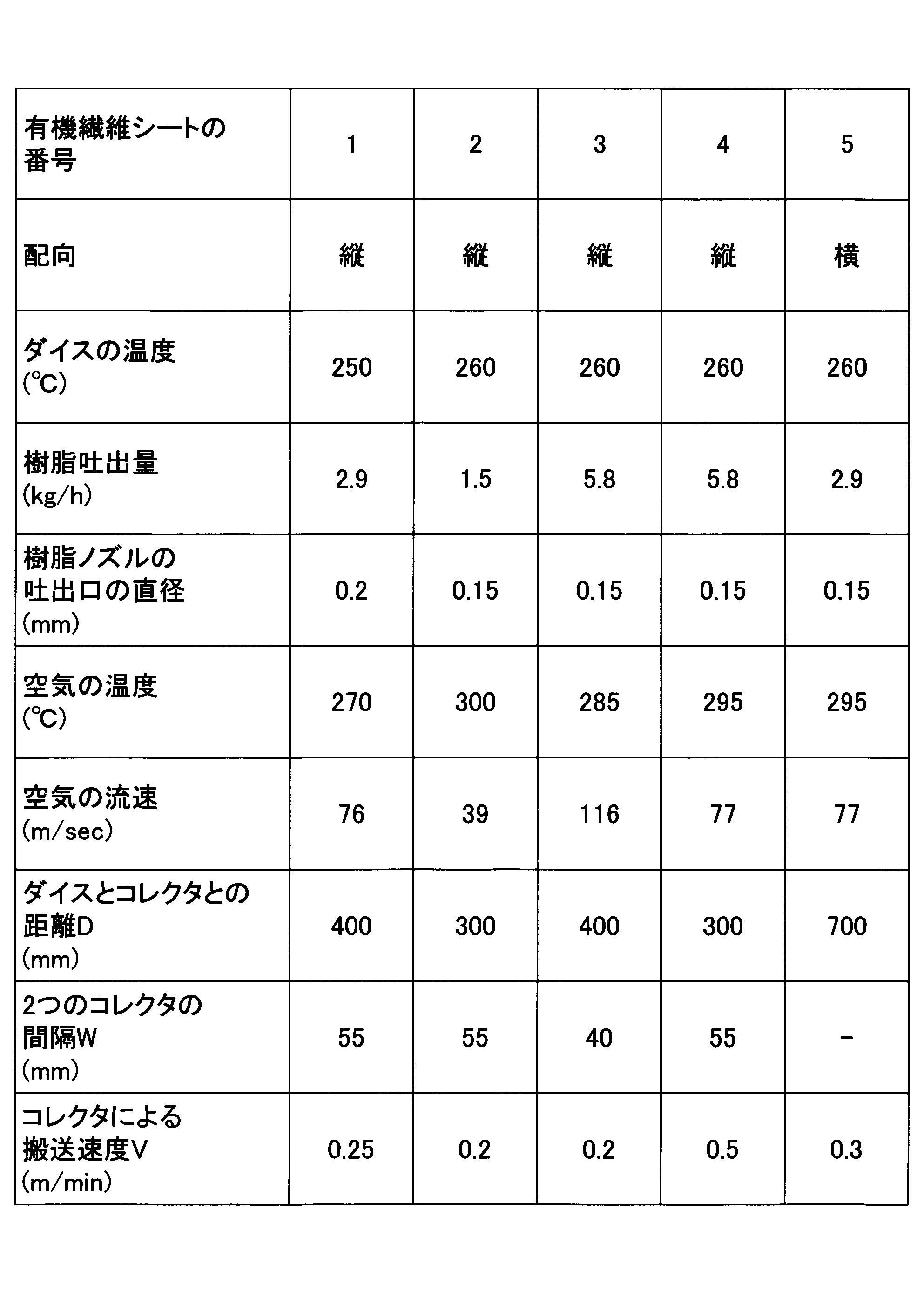
有機繊維シート6は、市販品のPETフェルトを用いた。
As the organic fiber sheet 6, a commercially available PET felt was used.
有機繊維シート1~6について、下記の測定を行った。尚、スキン層の厚さは、縦配向品の有機繊維シート1~4についてのみ測定した。
The following measurements were performed on the organic fiber sheets 1 to 6. The thickness of the skin layer was measured only for the vertically oriented organic fiber sheets 1 to 4.
<有機繊維シートの厚さ>
有機繊維シートの厚さは、有機繊維シートから切り出した試験片を台の水平な載置面に載せ、上方視で試験片の中心付近5点の厚さを厚みゲージで測定し、5点の測定値の算術平均値とした。試験片は、有機繊維シートの主表面に対し垂直な方向から見て縦100mm、横100mmの矩形状に切り出した。試験片は、試験片の切断面が台の載置面に対し垂直になるように、台の載置面に載せた。 <Thickness of organic fiber sheet>
The thickness of the organic fiber sheet was measured by placing a test piece cut from the organic fiber sheet on a horizontal mounting surface of a table, measuring the thickness of the five points near the center of the test piece with a thickness gauge from above, and measuring the thickness of the five points. The arithmetic mean of the measured values was used. The test piece was cut into a rectangular shape having a length of 100 mm and a width of 100 mm when viewed from a direction perpendicular to the main surface of the organic fiber sheet. The test piece was placed on the mounting surface of the table so that the cut surface of the test piece was perpendicular to the mounting surface of the table.
<スキン層の厚さ>
スキン層の厚さは、有機繊維シートから切り出した試験片の2つのスキン層のそれぞれの3点の厚さを厚みゲージで測定し、6点の測定値の算術平均値とした。試験片は、有機繊維シートのY軸方向中央部(図7および図11参照)から、有機繊維シートの主表面に対し垂直な方向から見て縦100mm、横100mmの矩形状に切り出した。尚、一方のスキン層の3点の厚さの算術平均値と、他方のスキン層の3点の厚さの算術平均値とは、誤差の範囲で一致した。 <Skin layer thickness>
The thickness of the skin layer was determined by measuring the thickness of each of the two skin layers of the two skin layers of the test piece cut from the organic fiber sheet with a thickness gauge and calculating the arithmetic average of the measured values at the six points. The test piece was cut out from the center of the organic fiber sheet in the Y-axis direction (see FIGS. 7 and 11) into a rectangular shape having a length of 100 mm and a width of 100 mm when viewed from a direction perpendicular to the main surface of the organic fiber sheet. The arithmetic mean value of the thickness of three points of one skin layer and the arithmetic mean value of the thickness of three points of the other skin layer matched within an error range.
<有機繊維シートの平均繊維径>
有機繊維シートの平均繊維径は、有機繊維シートから切り出した試験片のSEM写真(走査型電子顕微鏡写真)の画像解析によって測定した。試験片は、有機繊維シートの主表面に対し垂直な方向から見て縦5mm、横10mmの矩形状に切り出した。試験片の平均繊維径を測定する切断面には、予めスパッタ装置を用いてPt膜を形成した。
スパッタ装置としては、真空デバイス社製のマグネトロンスパッタ装置MSP-15を用いた。電流値は30mAとし、蒸着時間は30秒間とした。
走査型電子顕微鏡(SEM)としては、Phenom-World社製のproX PREMIUMIIを用いた。電子線のビームエネルギーは、10KeVとした。電子画像は、Phenom-World社製のPro SuiteフェノムアプリケーションシステムのAutomated Image Mappingを用い、1500倍の倍率で撮像場所を変えながら30枚取得した。
30枚の電子画像から合計1000箇所の繊維径を画像解析によって測定し、測定した繊維径の算術平均値を平均繊維径とした。画像解析には、Phenom-World社製のPro Suiteフェノムアプリケーションシステムのファイバーメトリックス機能を用いた。 <Average fiber diameter of organic fiber sheet>
The average fiber diameter of the organic fiber sheet was measured by image analysis of a SEM photograph (scanning electron micrograph) of a test piece cut from the organic fiber sheet. The test piece was cut into a rectangular shape having a length of 5 mm and a width of 10 mm as viewed from a direction perpendicular to the main surface of the organic fiber sheet. A Pt film was previously formed on the cut surface of the test piece for measuring the average fiber diameter using a sputtering apparatus.
As a sputtering device, a magnetron sputtering device MSP-15 manufactured by Vacuum Devices, Inc. was used. The current value was 30 mA, and the deposition time was 30 seconds.
As a scanning electron microscope (SEM), proX PREMIUMII manufactured by Phenom-World was used. The beam energy of the electron beam was set to 10 KeV. 30 electronic images were obtained using Automated Image Mapping of the Pro Suite phenom application system manufactured by Phenom-World while changing the imaging location at a magnification of 1500 times.
A total of 1000 fiber diameters were measured by image analysis from the 30 electronic images, and the arithmetic average of the measured fiber diameters was defined as the average fiber diameter. For the image analysis, the fiber metrics function of the Phenom-World Pro Suite phenom application system was used.
<有機繊維シートの固体占有率>
有機繊維シートの固体占有率は、有機繊維シートのかさ密度(BD)を固体の真密度(TD)で除した値(BD/TD)に100を乗じた値(BD/TD×100)として求めた。
有機繊維シートのかさ密度(BD)は、有機繊維シートから切り出した試験片の質量を、試験片の体積で除すことにより得た。試験片は、有機繊維シートの主表面に対し垂直な方向から見て直径100.5mmの円形に切り出した。試験片の体積は、直径100.5mmの円形の面積と有機繊維シートの総厚さとを乗じることにより測定した。試験片の質量は、電子天秤で測定した。
固体の真密度としては、固体を構成する有機繊維の真密度を用いた。有機繊維の材料として用いたPOLYMIRAE社製のポリプロピレン樹脂Moplen HP461Yの真密度は、920kg/m3であった。 <Solid occupancy of organic fiber sheet>
The solid occupancy of the organic fiber sheet is determined as a value (BD / TD × 100) obtained by multiplying 100 by a value (BD / TD) obtained by dividing the bulk density (BD) of the organic fiber sheet by the true density (TD) of the solid. Was.
The bulk density (BD) of the organic fiber sheet was obtained by dividing the mass of the test piece cut from the organic fiber sheet by the volume of the test piece. The test piece was cut into a circular shape having a diameter of 100.5 mm as viewed from a direction perpendicular to the main surface of the organic fiber sheet. The volume of the test piece was measured by multiplying the circular area having a diameter of 100.5 mm by the total thickness of the organic fiber sheet. The mass of the test piece was measured with an electronic balance.
The true density of the organic fibers constituting the solid was used as the true density of the solid. The true density of the polypropylene resin Moplen HP461Y manufactured by POLYMIRAE used as a material for the organic fiber was 920 kg / m 3 .
<有機繊維シートの減衰定数>
有機繊維シートの減衰定数(単位:Neper/m)は、日本音響エンジニアリング社製の垂直入射吸音率測定システムWinZacMTXを使用し、JIS A 1405-2に準拠して測定した。具体的には、固体占有率の測定に供した円柱状の試験片の片側の平面に対し垂直に音波を入射させ、音波の周波数を200Hzから1000Hzまで20Hzピッチで変化させたときのそれぞれの減衰定数を測定し、その41点の測定値の算術平均値を有機繊維シートの減衰定数とした。
尚、周波数が200Hz未満の減衰定数は、測定誤差が大きいため、測定の対象から除外した。 <Damping constant of organic fiber sheet>
The attenuation constant (unit: Neper / m) of the organic fiber sheet was measured according to JIS A 1405-2 using a normal incidence sound absorption coefficient measurement system WinZacMTX manufactured by Nippon Acoustic Engineering. Specifically, a sound wave is vertically incident on a plane on one side of the cylindrical test piece used for the measurement of the solid occupancy, and each attenuation when the frequency of the sound wave is changed from 200 Hz to 1000 Hz at a pitch of 20 Hz. The constants were measured, and the arithmetic average of the measured values at 41 points was defined as the attenuation constant of the organic fiber sheet.
Note that the attenuation constant having a frequency of less than 200 Hz has a large measurement error, and is therefore excluded from the measurement.
<有機繊維シートの特性インピーダンス>
有機繊維シートの特性インピーダンス(単位:N・s/m3)は、減衰定数と同様に、日本音響エンジニアリング社製の垂直入射吸音率測定システムWinZacMTXを使用し、JIS A 1405-2に準拠して測定した。具体的には、固体占有率の測定に供した円柱状の試験片の片側の平面に対し垂直に音波を入射させ、音波の周波数を200Hzから1000Hzまで20Hzピッチで変化させたときのそれぞれの特性インピーダンス(より詳細には特性インピーダンスの実部)を測定し、その41点の測定値の算術平均値を有機繊維シートの特性インピーダンスとした。 <Characteristic impedance of organic fiber sheet>
The characteristic impedance (unit: N · s / m 3 ) of the organic fiber sheet is measured in accordance with JIS A 1405-2 using the normal incidence sound absorption coefficient measurement system WinZacMTX manufactured by Nippon Acoustic Engineering Co., Ltd. in the same manner as the attenuation constant. It was measured. Specifically, each characteristic is obtained when a sound wave is vertically incident on a plane on one side of the cylindrical test piece used for measuring the solid occupancy, and the frequency of the sound wave is changed from 200 Hz to 1000 Hz at a pitch of 20 Hz. The impedance (more specifically, the real part of the characteristic impedance) was measured, and the arithmetic average of the measured values at 41 points was defined as the characteristic impedance of the organic fiber sheet.
表3に、有機繊維シート1~6の物性をまとめて示す。
Table 3 summarizes the physical properties of the organic fiber sheets 1 to 6.

有機繊維シート1~5は、平均繊維径が0.5μm以上14μm以下の範囲内であって且つ固体占有率Sが1.0%以上8.0%以下の範囲内であったため、高い減衰定数(10Neper/m以上)が得られた。一方、有機繊維シート6は、平均繊維径が14μmよりも大きかったため、減衰定数が低かった。
The organic fiber sheets 1 to 5 had a high attenuation constant because the average fiber diameter was in the range of 0.5 μm to 14 μm and the solid occupancy S was in the range of 1.0% to 8.0%. (10 Neper / m or more) was obtained. On the other hand, since the average fiber diameter of the organic fiber sheet 6 was larger than 14 μm, the attenuation constant was low.
[例1~例14]
例1では、1つの耐燃繊維シート1と1つの有機繊維シート1とを主表面同士を向い合せてホットメルトで接着することにより、試験シート1を作製した。例2では、例1と同様に、1つの耐燃繊維シート1と1つの有機繊維シート1とを主表面同士を向い合せてホットメルトで接着することにより、試験シート2を作製した。例3では、2つの耐燃繊維シート1の間に1つの有機繊維シート1を挟んでホットメルトで接着することにより、試験シート3を作製した。例4では、1つの耐燃繊維シート2と1つの有機繊維シート2とを主表面同士を向い合せてホットメルトで接着することにより、試験シート4を作製した。例5では、1つの耐燃繊維シート2と1つの有機繊維シート3とを主表面同士を向い合せてホットメルトで接着することにより、試験シート5を作製した。例6では、1つの耐燃繊維シート3と1つの有機繊維シート4とを主表面同士を向い合せてホットメルトで接着することにより、試験シート6を作製した。例7では、1つの耐燃繊維シート3と1つの有機繊維シート5とを主表面同士を向い合せてホットメルトで接着することにより、試験シート7を作製した。例8では、1つの耐燃繊維シート5と1つの有機繊維シート4とを主表面同士を向い合せてホットメルトで接着することにより、試験シート8を作製した。例9では、1つの耐燃繊維シート6と1つの有機繊維シート5とを主表面同士を向い合せてホットメルトで接着することにより、試験シート9を作製した。 [Examples 1 to 14]
In Example 1, a test sheet 1 was produced by bonding one flame-resistant fiber sheet 1 and one organic fiber sheet 1 with hot melts with their main surfaces facing each other. In Example 2, as in Example 1, onetest sheet 2 was produced by bonding one flame-resistant fiber sheet 1 and one organic fiber sheet 1 with hot melt with their main surfaces facing each other. In Example 3, a test sheet 3 was produced by sandwiching one organic fiber sheet 1 between two flame-resistant fiber sheets 1 and bonding them with a hot melt. In Example 4, a test sheet 4 was produced by bonding one flame-resistant fiber sheet 2 and one organic fiber sheet 2 with hot melt with their main surfaces facing each other. In Example 5, a test sheet 5 was produced by bonding one flame-resistant fiber sheet 2 and one organic fiber sheet 3 with their main surfaces facing each other with hot melt. In Example 6, a test sheet 6 was produced by bonding one flame-resistant fiber sheet 3 and one organic fiber sheet 4 with their main surfaces facing each other with hot melt. In Example 7, a test sheet 7 was produced by bonding one flame-resistant fiber sheet 3 and one organic fiber sheet 5 with hot melt with their main surfaces facing each other. In Example 8, a test sheet 8 was produced by bonding one flame-resistant fiber sheet 5 and one organic fiber sheet 4 with their main surfaces facing each other with hot melt. In Example 9, a test sheet 9 was produced by bonding one flame-resistant fiber sheet 6 and one organic fiber sheet 5 with their main surfaces facing each other with hot melt.
例1では、1つの耐燃繊維シート1と1つの有機繊維シート1とを主表面同士を向い合せてホットメルトで接着することにより、試験シート1を作製した。例2では、例1と同様に、1つの耐燃繊維シート1と1つの有機繊維シート1とを主表面同士を向い合せてホットメルトで接着することにより、試験シート2を作製した。例3では、2つの耐燃繊維シート1の間に1つの有機繊維シート1を挟んでホットメルトで接着することにより、試験シート3を作製した。例4では、1つの耐燃繊維シート2と1つの有機繊維シート2とを主表面同士を向い合せてホットメルトで接着することにより、試験シート4を作製した。例5では、1つの耐燃繊維シート2と1つの有機繊維シート3とを主表面同士を向い合せてホットメルトで接着することにより、試験シート5を作製した。例6では、1つの耐燃繊維シート3と1つの有機繊維シート4とを主表面同士を向い合せてホットメルトで接着することにより、試験シート6を作製した。例7では、1つの耐燃繊維シート3と1つの有機繊維シート5とを主表面同士を向い合せてホットメルトで接着することにより、試験シート7を作製した。例8では、1つの耐燃繊維シート5と1つの有機繊維シート4とを主表面同士を向い合せてホットメルトで接着することにより、試験シート8を作製した。例9では、1つの耐燃繊維シート6と1つの有機繊維シート5とを主表面同士を向い合せてホットメルトで接着することにより、試験シート9を作製した。 [Examples 1 to 14]
In Example 1, a test sheet 1 was produced by bonding one flame-resistant fiber sheet 1 and one organic fiber sheet 1 with hot melts with their main surfaces facing each other. In Example 2, as in Example 1, one
例10では、1つの耐燃繊維シート7のみを、試験シート10として用いた。例11では、1つの耐燃繊維シート1と1つの耐燃繊維シート8とを主表面同士を向い合せてホットメルトで接着することにより、試験シート11を作製した。例12では、1つの有機繊維シート1のみを、試験シート12として用いた。例13では、1つの耐燃繊維シート4と1つの有機繊維シート3とを主表面同士を向い合せてホットメルトで接着することにより、試験シート13を作製した。例14では、1つの耐燃繊維シート1と1つの有機繊維シート6とを主表面同士を向い合せてホットメルトで接着することにより、試験シート14を作製した。
で は In Example 10, only one flame-resistant fiber sheet 7 was used as the test sheet 10. In Example 11, the test sheet 11 was produced by bonding one flame-resistant fiber sheet 1 and one flame-resistant fiber sheet 8 with their main surfaces facing each other with hot melt. In Example 12, only one organic fiber sheet 1 was used as the test sheet 12. In Example 13, a test sheet 13 was produced by bonding one flame-resistant fiber sheet 4 and one organic fiber sheet 3 with hot melts with their main surfaces facing each other. In Example 14, a test sheet 14 was produced by bonding one flame-resistant fiber sheet 1 and one organic fiber sheet 6 with hot melt with their main surfaces facing each other.
<試験シートの軽量性>
軽量性の評価では、面密度が1550g/m2以下である場合に合格と判定し、それ以外の場合に不合格と判定した。 <Light weight of test sheet>
In the evaluation of lightness, it was determined to be acceptable when the areal density was 1550 g / m 2 or less, and was determined to be unacceptable otherwise.
軽量性の評価では、面密度が1550g/m2以下である場合に合格と判定し、それ以外の場合に不合格と判定した。 <Light weight of test sheet>
In the evaluation of lightness, it was determined to be acceptable when the areal density was 1550 g / m 2 or less, and was determined to be unacceptable otherwise.
<試験シートの防音性>
試験シート1~14の減衰定数は、有機繊維シート1~6の減衰定数と同様に測定した。また、試験シート1~14の特性インピーダンスは、有機繊維シート1~6の特性インピーダンスと同様に測定した。 <Sound insulation of test sheet>
The attenuation constants of the test sheets 1 to 14 were measured in the same manner as the attenuation constants of the organic fiber sheets 1 to 6. The characteristic impedances of the test sheets 1 to 14 were measured in the same manner as the characteristic impedances of the organic fiber sheets 1 to 6.
ここで、試験シート1、4~9、13~14の防音性の測定では、音源側に有機繊維シートを配し、音源とは反対側に耐燃繊維シートを配した。
Here, in the measurement of the soundproofness of the test sheets 1, 4 to 9, and 13 to 14, the organic fiber sheet was arranged on the sound source side, and the flame-resistant fiber sheet was arranged on the opposite side to the sound source.
但し、試験シート2の防音性の測定では、音源側に耐燃繊維シートを配し、音源とは反対側に有機繊維シートを配した。
However, in the measurement of the soundproofing of the test sheet 2, a flame-resistant fiber sheet was disposed on the sound source side, and an organic fiber sheet was disposed on the side opposite to the sound source.
また、試験シート11の防音性の測定では、音源側に耐燃繊維シート8を配し、音源とは反対側に耐燃繊維シート1を配した。
In addition, in the measurement of the soundproofing of the test sheet 11, the flame-resistant fiber sheet 8 was arranged on the sound source side, and the flame-resistant fiber sheet 1 was arranged on the side opposite to the sound source.
なお、試験シート3、10、12は、厚さ方向に対称な構造を有するので、適当に配した。
試 験 The test sheets 3, 10, and 12 had a structure symmetrical in the thickness direction, and thus were appropriately arranged.
防音性の評価では、遮音性と吸音性のいずれも合格である場合に合格と判定し、それ以外の場合に不合格と判定した。遮音性は、減衰定数が10Neper/m以上である場合に合格と判定し、それ以外の場合に不合格と判定した。また、吸音性は、特性インピーダンスが1400N・s/m3以下である場合に合格と判定し、それ以外の場合に不合格と判定した。
In the evaluation of the soundproofing properties, if both the sound insulating properties and the sound absorbing properties were acceptable, it was determined to be acceptable, and otherwise, it was determined to be unacceptable. The sound insulation was determined to be acceptable when the attenuation constant was 10 Neper / m or more, and was determined to be unacceptable otherwise. The sound absorption was determined to be acceptable when the characteristic impedance was 1400 N · s / m 3 or less, and was determined to be unacceptable otherwise.
<試験シートの燃焼試験>
図12に示す燃焼試験装置を用い、社団法人日本鉄道車両機械技術協会の鉄道車両用材料燃焼試験(一般材;鉄道車両用非金属材料の45°エチルアルコール試験)に準じて燃焼試験を行った。図12において、201は供試体(182mm×257mm)、202はアルコール容器(鉄製17.5φ×7.1、0.8t)、203はコルク製の容器受台を示す。 <Combustion test of test sheet>
Using the combustion test apparatus shown in FIG. 12, a combustion test was performed in accordance with a railway vehicle material combustion test (general material; 45 ° ethyl alcohol test of nonmetallic materials for railway vehicles) by the Japan Railway Rolling Stock Machine Technology Association. . In FIG. 12, 201 indicates a specimen (182 mm × 257 mm), 202 indicates an alcohol container (iron 17.5φ × 7.1, 0.8 t), and 203 indicates a container holder made of cork.
図12に示すように、供試体201は、水平面に対し45°傾斜させて保持した。供試体201が、試験シート1~14である。また、燃料容器(アルコール容器)202は、燃料容器202の底の中心が供試体201の下面中心の垂直下方25.4mmの位置になるように、コルク製の容器受台203に乗せた。
供 As shown in FIG. 12, the specimen 201 was held at an angle of 45 ° with respect to the horizontal plane. The specimen 201 is the test sheets 1 to 14. The fuel container (alcohol container) 202 was placed on a cork container holder 203 such that the center of the bottom of the fuel container 202 was positioned 25.4 mm vertically below the center of the lower surface of the specimen 201.
試験シート1、2、4~9、13~14の燃焼試験では、火源側(下側)に耐燃繊維シートを配し、火源とは反対側(上側)に有機繊維シートを配した。
燃 焼 In the combustion test of Test Sheets 1, 2, 4 to 9, and 13 to 14, the fire-resistant fiber sheet was provided on the fire source side (lower side), and the organic fiber sheet was provided on the side opposite to the fire source (upper side).
また、試験シート11の燃焼試験では、火源側(下側)に耐燃繊維シート1を配し、火源とは反対側(上側)に耐燃繊維シート8を配した。
In the combustion test of the test sheet 11, the fire-resistant fiber sheet 1 was disposed on the fire source side (lower side), and the fire-resistant fiber sheet 8 was disposed on the opposite side (upper side) from the fire source.
なお、試験シート3、10、12は、厚さ方向に対称な構造を有するので、適当に配した。
試 験 The test sheets 3, 10, and 12 had a structure symmetrical in the thickness direction, and thus were appropriately arranged.
燃料容器202に燃料であるエチルアルコール0.5ccを入れて、燃料に着火し、燃料が燃え尽きるまで約2分間放置した。その後、供試体201の状態を目視で観察し、(1)着炎の有無、(2)供試体201を厚さ方向に貫通する貫通穴の有無、(3)変形率を調べた。変形率とは、供試体201の上面(182mm×257mm)の全面積を100%に設定したときの、供試体201の上面の熱によって変形する部分の面積の比率である。
(5) 0.5 cc of ethyl alcohol as a fuel was placed in the fuel container 202, the fuel was ignited, and left for about 2 minutes until the fuel was burned out. Thereafter, the state of the specimen 201 was visually observed, and (1) the presence or absence of flame, (2) the presence or absence of a through-hole penetrating the specimen 201 in the thickness direction, and (3) the deformation ratio were examined. The deformation rate is a ratio of the area of the upper surface of the test piece 201 that is deformed by heat when the total area of the upper surface (182 mm × 257 mm) of the test piece 201 is set to 100%.
耐燃性の評価では、着炎が無く、貫通穴が無く、且つ変形率が50%以下である場合に合格と判定し、それ以外の場合に不合格と判定した。ここで、「着炎が無い」とは燃料が燃え尽きた後に供試体201が燃えないことを意味し、「着炎が有る」とは燃料が燃え尽きた後に供試体201が燃えることを意味する。
(4) In the evaluation of flame resistance, if there was no flame, there was no through hole, and the deformation rate was 50% or less, it was determined to be acceptable, and otherwise, it was determined to be unacceptable. Here, “there is no flame” means that the test piece 201 does not burn after the fuel has burned out, and “there is flame” means that the test piece 201 burns after the fuel has burned out.
<試験シートのフレキシブル性試験>
試験シートのフレキシブル性は、直径100mmの円筒の外周に試験シートを巻き付けて調べた。 <Flexibility test of test sheet>
The flexibility of the test sheet was examined by winding the test sheet around the outer circumference of a cylinder having a diameter of 100 mm.
試験シートのフレキシブル性は、直径100mmの円筒の外周に試験シートを巻き付けて調べた。 <Flexibility test of test sheet>
The flexibility of the test sheet was examined by winding the test sheet around the outer circumference of a cylinder having a diameter of 100 mm.
フレキシブル性の評価では、円筒の半周に亘って試験シートが隙間なく巻き付けられた場合を合格と判定し、それ以外の場合を不合格と判定した。
(4) In the evaluation of the flexibility, the case where the test sheet was wound around the half circumference of the cylinder without any gap was determined to be acceptable, and the other case was determined to be reject.
<総合の合否>
総合の合否では、軽量性、防音性、耐燃性およびフレキシブル性の全てにおいて合格の場合に合格と判定し、それ以外の場合に不合格と判定した。 <Comprehensive pass / fail>
Regarding the pass / fail of the overall evaluation, all of the lightweight, soundproof, flame-resistant and flexible properties were judged to be acceptable, and the other cases were judged to be unacceptable.
表4~表5に、試験シート1~14の評価結果を示す。
Tables 4 and 5 show the evaluation results of Test Sheets 1 to 14.


試験シート1~9は、試験シート10~14とは異なり、下記(1)~(4)の要件を全て満たすため、軽量性、防音性、耐燃性およびフレキシブル性の全てについて、合格と判定された。(1)試験シートが少なくとも1つの耐燃繊維シートと1つの有機繊維シートとを含む。(2)試験シートの面密度が、400g/m2以上1550g/m2以下である。(3)有機繊維シートは、平均繊維径が0.5μm以上14μm以下の有機繊維で形成される。(4)有機繊維シートの固体占有率が1.0%以上8.0%以下である。
The test sheets 1 to 9 are different from the test sheets 10 to 14 and satisfy all of the following requirements (1) to (4). Therefore, all of the lightness, soundproofing, flame resistance and flexibility are judged to be acceptable. Was. (1) The test sheet includes at least one flame resistant fiber sheet and one organic fiber sheet. (2) the surface density of the test sheet is 400 g / m 2 or more 1550 g / m 2 or less. (3) The organic fiber sheet is formed of organic fibers having an average fiber diameter of 0.5 μm or more and 14 μm or less. (4) The solid occupancy of the organic fiber sheet is 1.0% or more and 8.0% or less.
一方、試験シート10は、面密度が1550g/m2を超える耐燃繊維シート7のみで構成されるので、軽量性およびフレキシブル性について不合格と判定された。また、試験シート11は、試験シート1とは異なり、固体占有率が1.0%以上である有機繊維シート1に代えて、固体占有率が1.0%未満である耐燃繊維シート8を有するので、防音性(特に遮音性)について不合格と判定された。また、試験シート12は、試験シート1とは異なり、有機繊維シート1のみを有するので、耐燃性について不合格と判定された。また、試験シート13は、1550g/m2を超える面密度を有するので、軽量性について不合格と判定された。さらに、試験シート14は、1550g/m2を超える面密度を有するので、軽量性について不合格と判定された。
On the other hand, since the test sheet 10 was composed only of the flame-resistant fiber sheet 7 having an areal density exceeding 1550 g / m 2 , it was determined to be unacceptable for lightness and flexibility. Further, unlike the test sheet 1, the test sheet 11 has a flame-resistant fiber sheet 8 having a solid occupancy of less than 1.0% instead of the organic fiber sheet 1 having a solid occupancy of 1.0% or more. Therefore, it was determined that the soundproofing property (especially the soundproofing property) was rejected. Further, since the test sheet 12 has only the organic fiber sheet 1 unlike the test sheet 1, the test sheet 12 was determined to be unacceptable in terms of flame resistance. In addition, since the test sheet 13 had an areal density exceeding 1550 g / m 2 , it was determined to be unacceptable for lightness. Furthermore, since the test sheet 14 had an area density exceeding 1550 g / m 2 , it was determined to be unacceptable for lightness.
ところで、試験シート1と試験シート2とは、同じ1つの有機繊維シート1を有し、且つ同じ1つの耐燃繊維シート1とを有する。試験シート1の防音性と試験シート2の防音性とを比較すれば明らかなように、音源側に有機繊維シート1を配しても、音源とは反対側に有機繊維シート1を配しても、良好な防音性が得られることが分かる。
By the way, the test sheet 1 and the test sheet 2 have the same one organic fiber sheet 1 and the same one flame-resistant fiber sheet 1. As is clear from the comparison between the sound insulation of the test sheet 1 and the sound insulation of the test sheet 2, even if the organic fiber sheet 1 is arranged on the sound source side, the organic fiber sheet 1 is arranged on the opposite side to the sound source. Also, it can be seen that good soundproofing is obtained.
試験シート1、2は有機繊維シート1の片側に耐燃繊維シート1を有するのに対し、試験シート3は有機繊維シート1の両側に耐燃繊維シート1を有する。試験シート1、2の防音性と試験シート3の防音性とを比較すれば明らかなように、有機繊維シート1の片側に耐燃繊維シート1を配しても、有機繊維シート1の両側に耐燃繊維シート1を配しても、良好な防音性が得られることが分かる。
The test sheets 1 and 2 have the flame-resistant fiber sheet 1 on one side of the organic fiber sheet 1, whereas the test sheet 3 has the flame-resistant fiber sheet 1 on both sides of the organic fiber sheet 1. As is clear from the comparison between the soundproofing properties of the test sheets 1 and 2 and the soundproofing properties of the test sheet 3, even if the flameproofing fibersheet 1 is disposed on one side of the organic fibersheet 1, the flameproofing is provided on both sides of the organic fiber sheet 1 It can be seen that even with the fiber sheet 1, good soundproofing can be obtained.
以上、本開示に係る積層シートの実施形態について説明したが、本開示は上記実施形態などに限定されない。特許請求の範囲に記載された範疇内において、各種の変更、修正、置換、付加、削除、および組合わせが可能である。それらについても当然に本開示の技術的範囲に属する。
Although the embodiment of the laminated sheet according to the present disclosure has been described above, the present disclosure is not limited to the above embodiment and the like. Various changes, modifications, substitutions, additions, deletions, and combinations are possible within the scope of the claims. These naturally belong to the technical scope of the present disclosure.
例えば上記実施形態の積層シートは、入射する音波を減衰させる防音材として用いられるが、防音材以外の用途に用いられてもよい。防音材以外の用途としては、断熱材、制振材、または衝撃吸収材などが挙げられる。
For example, the laminated sheet of the above embodiment is used as a soundproofing material for attenuating incident sound waves, but may be used for applications other than the soundproofing material. Applications other than the soundproofing material include a heat insulating material, a vibration damping material, and a shock absorbing material.
本出願は、2018年8月23日に日本国特許庁に出願された特願2018-156312号に基づく優先権を主張するものであり、特願2018-156312号の全内容を本出願に援用する。
This application claims the priority based on Japanese Patent Application No. 2018-156212 filed with the Japan Patent Office on August 23, 2018, and incorporates the entire contents of Japanese Patent Application No. 2018-156312 into this application. I do.
2 積層シート
10 第1多孔質層
20 第2多孔質層
21、22 主表面
26 不織布層
27、28 スキン層 2Laminated sheet 10 First porous layer 20 Second porous layer 21, 22 Main surface 26 Non-woven fabric layer 27, 28 Skin layer
10 第1多孔質層
20 第2多孔質層
21、22 主表面
26 不織布層
27、28 スキン層 2
Claims (10)
- 無機繊維および炭化繊維の少なくとも1つを複数本含む第1多孔質層と、複数本の有機繊維で形成される第2多孔質層とを有する積層シートであって、
積層シートの面密度は、400g/m2以上1550g/m2以下であり、
前記第2多孔質層は、平均繊維径が0.5μm以上14μm以下の有機繊維で形成され、
前記第2多孔質層の単位体積に占める固体と空隙の全体積を100%とすると、前記固体の割合が1.0%以上8.0%以下である、積層シート。 A laminated sheet having a first porous layer including a plurality of at least one of inorganic fibers and carbonized fibers, and a second porous layer formed of a plurality of organic fibers,
The areal density of the laminated sheet is a 400 g / m 2 or more 1550 g / m 2 or less,
The second porous layer is formed of organic fibers having an average fiber diameter of 0.5 μm or more and 14 μm or less,
The laminated sheet, wherein the proportion of the solid is 1.0% or more and 8.0% or less, assuming that the total volume of solids and voids in the unit volume of the second porous layer is 100%. - 前記第2多孔質層を基準として前記第1多孔質層とは反対側に配置される第3多孔質層を有し、
前記第3多孔質層は、無機繊維および炭化繊維の少なくとも1つを複数本含む、請求項1に記載の積層シート。 A third porous layer disposed on a side opposite to the first porous layer with respect to the second porous layer,
The laminated sheet according to claim 1, wherein the third porous layer includes a plurality of at least one of an inorganic fiber and a carbonized fiber. - 前記第1多孔質層の厚さは、0.5mm以上10mm以下である、請求項1に記載の積層シート。 The laminated sheet according to claim 1, wherein the thickness of the first porous layer is 0.5 mm or more and 10 mm or less.
- 前記第1多孔質層の熱貫流率は、5.0W/m2・K以上1.0×103W/m2・K以下である、請求項1に記載の積層シート。 The heat transmission coefficient of the first porous layer is less 5.0W / m 2 · K or more 1.0 × 10 3 W / m 2 · K, the laminated sheet according to claim 1.
- 積層シートの厚さは、1mm以上100mm以下である、請求項1に記載の積層シート。 The laminated sheet according to claim 1, wherein the thickness of the laminated sheet is 1 mm or more and 100 mm or less.
- 前記第2多孔質層は、互いに対向する2つの主表面の間に、予め定められた面内方向に剥離可能に連続的に並ぶ複数の不織布層を有し、
複数の前記不織布層のそれぞれは、前記予め定められた面内方向から見たときに複数本の有機繊維が絡まり合うものである、請求項1に記載の積層シート。 The second porous layer has a plurality of nonwoven fabric layers continuously arranged so as to be peelable in a predetermined in-plane direction between two main surfaces facing each other,
The laminated sheet according to claim 1, wherein each of the plurality of nonwoven fabric layers includes a plurality of organic fibers tangled when viewed from the predetermined in-plane direction. - 前記第2多孔質層は、互いに対向する2つの主表面のそれぞれに、厚さ方向から見たときに複数本の有機繊維が絡まり合うスキン層を有し、
複数の前記不織布層は、2つの前記スキン層の間に設けられ、それぞれ、2つの前記スキン層と連続的に形成され、
2つの前記スキン層のそれぞれの厚さは、0.01mm以上5mm以下である、請求項6に記載の積層シート。 The second porous layer has, on each of the two main surfaces facing each other, a skin layer in which a plurality of organic fibers are entangled when viewed from the thickness direction,
The plurality of nonwoven fabric layers are provided between two of the skin layers, and are each formed continuously with the two skin layers,
The laminated sheet according to claim 6, wherein each of the two skin layers has a thickness of 0.01 mm or more and 5 mm or less. - 積層シートの減衰定数は、10Neper/m以上30Neper/m以下である、請求項1に記載の積層シート。 The laminated sheet according to claim 1, wherein the attenuation constant of the laminated sheet is 10 Neper / m or more and 30 Neper / m or less.
- 積層シートの特性インピーダンスは、300N・s/m3以上1400N・s/m3以下である、請求項1に記載の積層シート。 The characteristic impedance of the laminated sheet is 300N · s / m 3 or more 1400N · s / m 3 or less, the laminated sheet according to claim 1.
- 積層シートは、入射する音波を減衰させる防音材として用いられる、請求項1に記載の積層シート。 The laminated sheet according to claim 1, wherein the laminated sheet is used as a soundproofing material that attenuates incident sound waves.
Priority Applications (3)
| Application Number | Priority Date | Filing Date | Title |
|---|---|---|---|
| EP19852943.0A EP3842227A4 (en) | 2018-08-23 | 2019-05-30 | Layered sheet |
| CN201980054235.XA CN112566780B (en) | 2018-08-23 | 2019-05-30 | Laminated sheet |
| US17/269,452 US11951729B2 (en) | 2018-08-23 | 2019-05-30 | Laminated sheet |
Applications Claiming Priority (2)
| Application Number | Priority Date | Filing Date | Title |
|---|---|---|---|
| JP2018-156312 | 2018-08-23 | ||
| JP2018156312A JP7097781B2 (en) | 2018-08-23 | 2018-08-23 | Laminated sheet |
Publications (1)
| Publication Number | Publication Date |
|---|---|
| WO2020039681A1 true WO2020039681A1 (en) | 2020-02-27 |
Family
ID=69592614
Family Applications (1)
| Application Number | Title | Priority Date | Filing Date |
|---|---|---|---|
| PCT/JP2019/021517 WO2020039681A1 (en) | 2018-08-23 | 2019-05-30 | Layered sheet |
Country Status (5)
| Country | Link |
|---|---|
| US (1) | US11951729B2 (en) |
| EP (1) | EP3842227A4 (en) |
| JP (1) | JP7097781B2 (en) |
| CN (1) | CN112566780B (en) |
| WO (1) | WO2020039681A1 (en) |
Cited By (1)
| Publication number | Priority date | Publication date | Assignee | Title |
|---|---|---|---|---|
| WO2022186289A1 (en) * | 2021-03-03 | 2022-09-09 | 旭化成アドバンス株式会社 | Battery unit |
Citations (7)
| Publication number | Priority date | Publication date | Assignee | Title |
|---|---|---|---|---|
| JPS63121530U (en) * | 1987-01-30 | 1988-08-08 | ||
| JP2001271438A (en) * | 2000-03-24 | 2001-10-05 | Bridgestone Corp | Outdoor sound absorbing material |
| JP2001316961A (en) * | 2000-05-09 | 2001-11-16 | Toyobo Co Ltd | Sound-absorbing structural body |
| JP2008076871A (en) | 2006-09-22 | 2008-04-03 | Swcc Showa Device Technology Co Ltd | Sound absorber and sound absorbing structure using thr same |
| JP2014232281A (en) * | 2013-05-30 | 2014-12-11 | 帝人株式会社 | Sound absorption material |
| JP2018156312A (en) | 2017-03-16 | 2018-10-04 | Kddi株式会社 | Terminal device, information management device, data management method, and computer program |
| WO2019107019A1 (en) * | 2017-11-28 | 2019-06-06 | 日東電工株式会社 | Porous fiber sheet |
Family Cites Families (19)
| Publication number | Priority date | Publication date | Assignee | Title |
|---|---|---|---|---|
| US3795288A (en) * | 1968-05-27 | 1974-03-05 | Pall Corp | Gas conduit with acoustic insulation comprising anisometric compressed and bonded multilayer knitted wire mesh composites |
| JPS5668152A (en) | 1979-11-01 | 1981-06-08 | Toa Nenryo Kogyo Kk | Nonwoven fabric |
| US7476632B2 (en) * | 2002-11-15 | 2009-01-13 | 3M Innovative Properties Company | Fibrous nonwoven web |
| JP2005335279A (en) | 2004-05-28 | 2005-12-08 | Du Pont Toray Co Ltd | Easy-to-mold sound-absorbing material |
| JP2006002429A (en) | 2004-06-17 | 2006-01-05 | Nihon Glassfiber Industrial Co Ltd | Radio wave-sound wave absorbing thermal insulation body |
| US7461437B2 (en) * | 2004-11-15 | 2008-12-09 | Velcro Industries B.V. | Articles and methods of their formation |
| US8906815B2 (en) * | 2007-12-28 | 2014-12-09 | 3M Innovative Properties Company | Composite nonwoven fibrous webs and methods of making and using the same |
| CN101195938B (en) | 2008-01-08 | 2010-08-11 | 中国人民解放军国防科学技术大学 | Core-skin structure micropore silicon carbide fiber and method for producing the same |
| US8486516B2 (en) * | 2008-08-29 | 2013-07-16 | Certainteed Gypsum, Inc. | Plastic coated composite building boards and method of making same |
| KR101233813B1 (en) * | 2010-07-12 | 2013-02-14 | (주)리앤에스 | Thermoplastic organic fiber, method for preparing the same, fiber composite board using the same and method for preparing the board |
| EP2503040A1 (en) * | 2011-03-23 | 2012-09-26 | Autoneum Management AG | Moulded multilayer lining |
| JP6045915B2 (en) * | 2011-07-05 | 2016-12-14 | 豊和繊維工業株式会社 | Method for manufacturing vehicle package tray |
| JP5863474B2 (en) | 2012-01-20 | 2016-02-16 | 三井化学株式会社 | Melt-blown nonwoven fabric, its use, and its production method |
| US20130327705A1 (en) * | 2012-06-08 | 2013-12-12 | Edward J. Clark | Heated collectors, nonwoven materials produced therefrom, and methods relating thereto |
| WO2014030730A1 (en) | 2012-08-23 | 2014-02-27 | 三井化学株式会社 | Melt-blown nonwoven fabric and use thereof |
| US10961644B2 (en) * | 2014-01-29 | 2021-03-30 | Biax-Fiberfilm Corporation | High loft, nonwoven web exhibiting excellent recovery |
| CN106103196B (en) | 2014-03-25 | 2018-06-05 | 林天连布有限公司 | Automobile using damper element |
| CN109072488B (en) | 2016-04-27 | 2021-10-15 | 东丽株式会社 | Porous fiber, adsorbent, and purification column |
| JP6614450B2 (en) | 2016-05-11 | 2019-12-04 | パナソニックIpマネジメント株式会社 | Nonwoven fabric and sound absorbing material |
-
2018
- 2018-08-23 JP JP2018156312A patent/JP7097781B2/en active Active
-
2019
- 2019-05-30 WO PCT/JP2019/021517 patent/WO2020039681A1/en unknown
- 2019-05-30 CN CN201980054235.XA patent/CN112566780B/en active Active
- 2019-05-30 US US17/269,452 patent/US11951729B2/en active Active
- 2019-05-30 EP EP19852943.0A patent/EP3842227A4/en active Pending
Patent Citations (7)
| Publication number | Priority date | Publication date | Assignee | Title |
|---|---|---|---|---|
| JPS63121530U (en) * | 1987-01-30 | 1988-08-08 | ||
| JP2001271438A (en) * | 2000-03-24 | 2001-10-05 | Bridgestone Corp | Outdoor sound absorbing material |
| JP2001316961A (en) * | 2000-05-09 | 2001-11-16 | Toyobo Co Ltd | Sound-absorbing structural body |
| JP2008076871A (en) | 2006-09-22 | 2008-04-03 | Swcc Showa Device Technology Co Ltd | Sound absorber and sound absorbing structure using thr same |
| JP2014232281A (en) * | 2013-05-30 | 2014-12-11 | 帝人株式会社 | Sound absorption material |
| JP2018156312A (en) | 2017-03-16 | 2018-10-04 | Kddi株式会社 | Terminal device, information management device, data management method, and computer program |
| WO2019107019A1 (en) * | 2017-11-28 | 2019-06-06 | 日東電工株式会社 | Porous fiber sheet |
Non-Patent Citations (1)
| Title |
|---|
| See also references of EP3842227A4 |
Cited By (1)
| Publication number | Priority date | Publication date | Assignee | Title |
|---|---|---|---|---|
| WO2022186289A1 (en) * | 2021-03-03 | 2022-09-09 | 旭化成アドバンス株式会社 | Battery unit |
Also Published As
| Publication number | Publication date |
|---|---|
| US11951729B2 (en) | 2024-04-09 |
| CN112566780B (en) | 2023-01-03 |
| EP3842227A4 (en) | 2022-05-18 |
| US20210237396A1 (en) | 2021-08-05 |
| EP3842227A1 (en) | 2021-06-30 |
| CN112566780A (en) | 2021-03-26 |
| JP7097781B2 (en) | 2022-07-08 |
| JP2020029046A (en) | 2020-02-27 |
Similar Documents
| Publication | Publication Date | Title |
|---|---|---|
| US8496088B2 (en) | Acoustic composite | |
| US8322487B1 (en) | Acoustically coupled non-woven composite | |
| WO2019107019A1 (en) | Porous fiber sheet | |
| JP2014224648A (en) | Flame-proof heat insulation material, and flame-proof heat insulation material for vehicle | |
| US9505359B2 (en) | Sound-absorbing material and wire harness equipped with sound-absorbing material | |
| KR102601130B1 (en) | Laminated sound absorbing material | |
| JP6904445B2 (en) | Flame-retardant sound absorbing material | |
| US9570061B2 (en) | Acoustic material and wire harness with acoustic material | |
| WO2016121467A1 (en) | Sound-absorbing material and wiring harness with sound-absorbing material | |
| JP6764482B2 (en) | Sound absorbing insulation | |
| WO2020039681A1 (en) | Layered sheet | |
| US11270680B2 (en) | Soundproof structure and method of manufacturing soundproof structure | |
| JP2006321053A (en) | Heat-resistant sound-absorbing and heat insulating material | |
| WO2019004408A1 (en) | Fiber aggregate for sound insulation, sound absorbing/insulating material, and sound absorbing/insulating material for vehicle | |
| WO2020039680A1 (en) | Laminate sheet | |
| JP2018028314A (en) | Sound absorption structure and manufacturing method of sound absorption structure | |
| JP6646267B1 (en) | Laminated sound absorbing material | |
| JP2017037173A (en) | Sound absorbing felt | |
| JP2024065446A (en) | Composite sound absorbing material | |
| US20210339687A1 (en) | Sound-absorbing material | |
| JP2024065447A (en) | Laminated sound absorbing material | |
| WO2022009143A1 (en) | Sound absorbing material and method of producing sound absorbing material | |
| KR20240010649A (en) | High Sound-Absorbing Nonwoven Fabric Using Double Hole Fibers | |
| JP2005195637A (en) | Acoustic material | |
| CZ303670B6 (en) | Method of producing fibrous sound-absorbing fabric and fibrous sound-absorbing fabric produced in such a manner |
Legal Events
| Date | Code | Title | Description |
|---|---|---|---|
| 121 | Ep: the epo has been informed by wipo that ep was designated in this application |
Ref document number: 19852943 Country of ref document: EP Kind code of ref document: A1 |
|
| NENP | Non-entry into the national phase |
Ref country code: DE |
|
| ENP | Entry into the national phase |
Ref document number: 2019852943 Country of ref document: EP Effective date: 20210323 |