WO2020036112A1 - Medical system, medical light source device and method for medical light source device - Google Patents
Medical system, medical light source device and method for medical light source device Download PDFInfo
- Publication number
- WO2020036112A1 WO2020036112A1 PCT/JP2019/031277 JP2019031277W WO2020036112A1 WO 2020036112 A1 WO2020036112 A1 WO 2020036112A1 JP 2019031277 W JP2019031277 W JP 2019031277W WO 2020036112 A1 WO2020036112 A1 WO 2020036112A1
- Authority
- WO
- WIPO (PCT)
- Prior art keywords
- light
- light source
- radiation angle
- source device
- medical
- Prior art date
Links
Images


Classifications
-
- A—HUMAN NECESSITIES
- A61—MEDICAL OR VETERINARY SCIENCE; HYGIENE
- A61B—DIAGNOSIS; SURGERY; IDENTIFICATION
- A61B1/00—Instruments for performing medical examinations of the interior of cavities or tubes of the body by visual or photographical inspection, e.g. endoscopes; Illuminating arrangements therefor
- A61B1/06—Instruments for performing medical examinations of the interior of cavities or tubes of the body by visual or photographical inspection, e.g. endoscopes; Illuminating arrangements therefor with illuminating arrangements
- A61B1/07—Instruments for performing medical examinations of the interior of cavities or tubes of the body by visual or photographical inspection, e.g. endoscopes; Illuminating arrangements therefor with illuminating arrangements using light-conductive means, e.g. optical fibres
-
- A—HUMAN NECESSITIES
- A61—MEDICAL OR VETERINARY SCIENCE; HYGIENE
- A61B—DIAGNOSIS; SURGERY; IDENTIFICATION
- A61B1/00—Instruments for performing medical examinations of the interior of cavities or tubes of the body by visual or photographical inspection, e.g. endoscopes; Illuminating arrangements therefor
- A61B1/00002—Operational features of endoscopes
- A61B1/00004—Operational features of endoscopes characterised by electronic signal processing
- A61B1/00009—Operational features of endoscopes characterised by electronic signal processing of image signals during a use of endoscope
- A61B1/000095—Operational features of endoscopes characterised by electronic signal processing of image signals during a use of endoscope for image enhancement
-
- A—HUMAN NECESSITIES
- A61—MEDICAL OR VETERINARY SCIENCE; HYGIENE
- A61B—DIAGNOSIS; SURGERY; IDENTIFICATION
- A61B1/00—Instruments for performing medical examinations of the interior of cavities or tubes of the body by visual or photographical inspection, e.g. endoscopes; Illuminating arrangements therefor
- A61B1/00064—Constructional details of the endoscope body
- A61B1/00071—Insertion part of the endoscope body
- A61B1/0008—Insertion part of the endoscope body characterised by distal tip features
- A61B1/00096—Optical elements
-
- A—HUMAN NECESSITIES
- A61—MEDICAL OR VETERINARY SCIENCE; HYGIENE
- A61B—DIAGNOSIS; SURGERY; IDENTIFICATION
- A61B1/00—Instruments for performing medical examinations of the interior of cavities or tubes of the body by visual or photographical inspection, e.g. endoscopes; Illuminating arrangements therefor
- A61B1/04—Instruments for performing medical examinations of the interior of cavities or tubes of the body by visual or photographical inspection, e.g. endoscopes; Illuminating arrangements therefor combined with photographic or television appliances
- A61B1/05—Instruments for performing medical examinations of the interior of cavities or tubes of the body by visual or photographical inspection, e.g. endoscopes; Illuminating arrangements therefor combined with photographic or television appliances characterised by the image sensor, e.g. camera, being in the distal end portion
-
- A—HUMAN NECESSITIES
- A61—MEDICAL OR VETERINARY SCIENCE; HYGIENE
- A61B—DIAGNOSIS; SURGERY; IDENTIFICATION
- A61B1/00—Instruments for performing medical examinations of the interior of cavities or tubes of the body by visual or photographical inspection, e.g. endoscopes; Illuminating arrangements therefor
- A61B1/06—Instruments for performing medical examinations of the interior of cavities or tubes of the body by visual or photographical inspection, e.g. endoscopes; Illuminating arrangements therefor with illuminating arrangements
- A61B1/0638—Instruments for performing medical examinations of the interior of cavities or tubes of the body by visual or photographical inspection, e.g. endoscopes; Illuminating arrangements therefor with illuminating arrangements providing two or more wavelengths
-
- A—HUMAN NECESSITIES
- A61—MEDICAL OR VETERINARY SCIENCE; HYGIENE
- A61B—DIAGNOSIS; SURGERY; IDENTIFICATION
- A61B1/00—Instruments for performing medical examinations of the interior of cavities or tubes of the body by visual or photographical inspection, e.g. endoscopes; Illuminating arrangements therefor
- A61B1/06—Instruments for performing medical examinations of the interior of cavities or tubes of the body by visual or photographical inspection, e.g. endoscopes; Illuminating arrangements therefor with illuminating arrangements
- A61B1/0646—Instruments for performing medical examinations of the interior of cavities or tubes of the body by visual or photographical inspection, e.g. endoscopes; Illuminating arrangements therefor with illuminating arrangements with illumination filters
-
- A—HUMAN NECESSITIES
- A61—MEDICAL OR VETERINARY SCIENCE; HYGIENE
- A61B—DIAGNOSIS; SURGERY; IDENTIFICATION
- A61B1/00—Instruments for performing medical examinations of the interior of cavities or tubes of the body by visual or photographical inspection, e.g. endoscopes; Illuminating arrangements therefor
- A61B1/06—Instruments for performing medical examinations of the interior of cavities or tubes of the body by visual or photographical inspection, e.g. endoscopes; Illuminating arrangements therefor with illuminating arrangements
- A61B1/0661—Endoscope light sources
- A61B1/0669—Endoscope light sources at proximal end of an endoscope
-
- G—PHYSICS
- G02—OPTICS
- G02B—OPTICAL ELEMENTS, SYSTEMS OR APPARATUS
- G02B21/00—Microscopes
- G02B21/06—Means for illuminating specimens
-
- G—PHYSICS
- G02—OPTICS
- G02B—OPTICAL ELEMENTS, SYSTEMS OR APPARATUS
- G02B23/00—Telescopes, e.g. binoculars; Periscopes; Instruments for viewing the inside of hollow bodies; Viewfinders; Optical aiming or sighting devices
- G02B23/24—Instruments or systems for viewing the inside of hollow bodies, e.g. fibrescopes
- G02B23/2407—Optical details
- G02B23/2461—Illumination
-
- A—HUMAN NECESSITIES
- A61—MEDICAL OR VETERINARY SCIENCE; HYGIENE
- A61B—DIAGNOSIS; SURGERY; IDENTIFICATION
- A61B1/00—Instruments for performing medical examinations of the interior of cavities or tubes of the body by visual or photographical inspection, e.g. endoscopes; Illuminating arrangements therefor
- A61B1/00147—Holding or positioning arrangements
- A61B1/00149—Holding or positioning arrangements using articulated arms
Definitions
- the present disclosure relates to a medical system, a medical light source device, and a method in a medical light source device.
- Patent Document 1 describes that at least one laser light source is provided and light from the laser light source is incident on a light guide.
- lamp light sources xenon lamps and halogen lamps
- white LEDs and the like are mainly used.
- these light sources have a large light emitting point size and a wide radiation angle, so that it is difficult to efficiently condense light on a small diameter light guide.
- a semiconductor laser with a small emission point size and a narrow emission angle to combine red light, green light, and blue light to generate white light and use it as a medical light source.
- a semiconductor laser has a narrow wavelength width, for example, white light generated by combining red light, green light, and blue light has low color rendering.
- the white light generated by the semiconductor laser and white light obtained from another light source are combined to enhance the color rendering of the white light generated by the semiconductor laser, the color of the white light is changed due to the difference in the emission angle of both white lights. There is a problem that it shifts and causes unevenness. This is because the emission angle distribution of the white light generated by the semiconductor laser has a Gaussian shape, whereas the emission angle distribution of the white light of another light source (such as an LED) has a Lambertian shape.
- the operator may misdiagnose the diagnosis, for example, when judging the lesion, tumor, etc. of the affected part by color. There is.
- the operator moves an affected part to the center of the image by operating a device such as an endoscope or a microscope in order to make an appropriate determination. This necessitates a very complicated operation.
- a medical device including an imaging unit that captures an image of an observation target, and a light source device that generates light for irradiating the observation target, the light source device has a narrow wavelength band having a narrow band.
- a narrow-band light source that emits band light
- a broad-band light source that emits broad-band light whose wavelength width is wider than the narrow-band light
- a multiplexing unit that multiplexes the narrow-band light and the broad-band light
- a medical system comprising: a radiation angle conversion unit that converts a radiation angle of narrowband light.
- a narrow-band light source that emits narrow-band light whose wavelength width is a narrow band
- a broad-band light source that emits broad-band light whose wavelength width is wider than the narrow-band light
- a medical light source device comprising: a multiplexing unit that multiplexes band light and the broadband light; and a radiation angle conversion unit that converts a radiation angle of the narrowband light.
- the narrow-band light having a narrow wavelength band and the wide-band light having the wide wavelength band is wider than the narrow-band light, and the narrow-band light before the multiplexing, Converting the angle of emission of light, the method in a medical light source device.
- FIG. 1 is a schematic diagram illustrating a schematic configuration of a light source device according to an embodiment of the present disclosure and its periphery.
- FIG. 3 is a characteristic diagram illustrating a radiation angle distribution of narrowband light.
- FIG. 4 is a characteristic diagram illustrating a radiation angle distribution of broadband light.
- FIG. 4 is a characteristic diagram showing a radiation angle distribution of narrowband light shown in FIG. 2 and a radiation angle distribution of broadband light shown in FIG. 3 superimposed.
- FIG. 4 is a characteristic diagram illustrating a radiation angle distribution of narrow-band light transmitted through a radiation angle conversion element.
- FIG. 4 is a characteristic diagram showing characteristics obtained by changing the emission angle distribution of the broadband light by performing NA restriction on the broadband light shown in FIG. 3.
- FIG. 3 is a characteristic diagram illustrating a radiation angle distribution of narrowband light.
- FIG. 4 is a characteristic diagram illustrating a radiation angle distribution of broadband light. 2 and a radiation angle distribution of broadband light shown in FIG. 3 superimposed.
- FIG. 4 is
- FIG. 7 is a characteristic diagram in which a radiation angle distribution of narrow-band light transmitted through the radiation angle conversion element illustrated in FIG. 5 and a radiation angle distribution of broadband light with NA restriction illustrated in FIG. 6 are superimposed. It is a schematic diagram showing an example using a rod integrator as a radiation angle conversion element.
- FIG. 4 is a schematic diagram illustrating a method of restricting NA of broadband light by an aperture.
- FIG. 4 is a schematic diagram illustrating a method of restricting NA of broadband light by an aperture.
- It is a schematic diagram which shows an example of the narrow-band light source which combines narrow-band light from several wavelengths.
- FIG. 12 is a schematic diagram illustrating a configuration example in which a yellow light source, a dichroic mirror, and an aperture are added to the narrow-band light source illustrated in FIG. 11.
- 1 is a diagram illustrating an example of a schematic configuration of an endoscopic surgery system to which a light source device according to the present disclosure can be applied.
- 1 is a diagram illustrating an example of a schematic configuration of a microsurgery system to which a light source device according to the present disclosure can be applied.
- an endoscope As a device for observing the internal structure of a target, an endoscope is widely used. Particularly in the medical field, endoscopes have rapidly spread with the development of surgical techniques and are now indispensable in many medical fields. In recent years, endoscope devices have been required to have low invasiveness to patients, regardless of whether they are flexible or rigid, and in particular, scopes that directly touch the patient have been continuously improved to reduce the diameter and size. . Along with this, a problem has arisen for a light source device as an illumination device for illuminating an affected part to efficiently guide light to a thinner light guide.
- Lamps xenon lamps and halogen lamps
- white LEDs are mainly used as illumination light sources for conventional endoscope devices, but both have large emission points and large radiation angles (large etendue). It has been difficult to efficiently focus light on a small-diameter light guide.
- the present embodiment proposes a light source device using a semiconductor laser (LD) having a small light emitting point size and a narrow radiation angle (small etendue).
- a semiconductor laser since a semiconductor laser has a narrow wavelength width, it is generally known that, for example, white light generated by combining red light, green light, and blue light has poor color rendering properties.
- the color rendering property is deteriorated, for example, when a malignant tumor is determined, there is a possibility that a doctor's diagnosis by endoscopic observation may be erroneously recognized. Therefore, in the present embodiment, a light source having a wide wavelength width is used as an auxiliary light source and mixed with laser light to improve color rendering.
- white light generated by combining red light, green light, and blue light does not have light with a wavelength in between these colors. It can be optimized and color rendering can be improved.
- a light guide (LG) in which an optical fiber is bundled to guide light from a light source generally emits illumination light in which a radiation angle distribution of incident light is preserved. For this reason, when light from a semiconductor laser is guided to a light guide, the laser light generally has a Gaussian-shaped emission angle distribution, so that the illumination light becomes brighter at the center of the optical axis and becomes darker toward the periphery.
- broadband light for example, white LED
- white LED used as an auxiliary light source
- broadband light generally has a Lambertian radiation angle distribution, and therefore becomes illumination light in which the amount of light hardly decreases even in a peripheral portion.
- the ratio between the laser light and the broadband light is shifted between the central part and the peripheral part, so that unevenness (particularly color unevenness) occurs in the illumination light.
- an auxiliary light source such as a white LED
- the color of white is shifted. Therefore, in order to realize a light source having a high color rendering property by mixing a laser light with an auxiliary light source such as a white LED, it is necessary to suppress the unevenness of the illumination light.
- a light source device for suppressing unevenness of illumination light is proposed. The details will be described below.
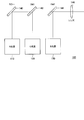
- the light source device 1000 includes a narrow band light source 100, a wide band light source 200, a lens 300, a lens 305, a dichroic mirror (combining unit) 310, a lens 320, a lens 330, and a radiation angle conversion.
- An element (radiation angle conversion unit) 400 is provided. The light emitted from the light source device 1000 passes through the light guide 500 and is guided to the observation optical system 600.
- the narrow band light source 100 is composed of a semiconductor laser and emits narrow band light.
- the broadband light source 200 includes a white LED and emits white broadband light. Although a white LED is exemplified as the broadband light source 200, a light source such as a xenon lamp or a halogen lamp may be used. Further, the broadband light source 200 may be a phosphor that emits fluorescent light.
- the narrow band light is collimated by the lens 300 and is incident on the radiation angle conversion element 400.
- the radiation angle conversion element 400 assumes a diffusion plate, for example, and plays a role of giving a desired light distribution angle to the incident collimated light and a role of converting the radiation angle distribution.
- Light emitted from the radiation angle conversion element 400 is collimated by a lens 305, passes through a dichroic mirror 310 for multiplexing, and is condensed on a light guide 500 by a lens 320.
- the broadband light is collimated by the lens 330, reflected by the dichroic mirror 310, combined with the narrowband light, and collected by the lens 320 on the light guide 500.
- the dichroic mirror 310 has a characteristic that the wavelength component of the narrow band light is transmitted and the other wavelength band is reflected.
- the dichroic mirror 310 can combine narrowband light and broadband light.
- techniques such as wavelength multiplexing, polarization multiplexing, and spatial multiplexing can be used as the multiplexing technique.
- the light guide 500 can use a bundle of multi-mode fibers of several tens of ⁇ m often used in medical devices.
- the collected illumination light is guided to the observation optical system 600 through the light guide 500.
- the observation optical system 600 corresponds to an in-scope optical system for an endoscope application and a microscope optical system for an operation microscope application, and light emitted from the light source device 1000 irradiates an actual observation target as illumination light therethrough. Is done.
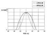
- FIG. 2 is a characteristic diagram showing a radiation angle distribution of narrowband light.
- the horizontal axis represents the radiation angle
- the vertical axis represents the light intensity.
- the intensity of light near the radiation angle of 0 degree is high, and the distribution of the intensity with respect to the radiation angle is a Gaussian distribution.
- FIG. 3 is a characteristic diagram showing a radiation angle distribution of broadband light. Also in FIG. 3, the horizontal axis represents the radiation angle, and the vertical axis represents the light intensity. Broadband light has less change in light intensity centered on a radiation angle of 0 degrees than narrowband light, and the distribution of light intensity with respect to the radiation angle is a Lambertian distribution.
- FIG. 4 is a characteristic diagram in which the emission angle distribution of the narrowband light shown in FIG. 2 and the emission angle distribution of the broadband light shown in FIG. 3 are superimposed, and shows a state where the narrowband light and the broadband light are multiplexed as they are. Is shown.
- the intensity of the broadband light source and the intensity of the narrowband light source are almost the same near the center (radiation angle 0 °), but the intensity of the narrowband light source decreases more in the periphery. This indicates that the intensity ratio between the narrow band light source and the wide band light source is different between the central part and the peripheral part, and the above-described unevenness occurs.
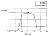
- FIG. 5 is a characteristic diagram showing a radiation angle distribution of the narrowband light transmitted through the radiation angle conversion element 400.
- the radiation angle distribution of the narrowband light expands, and the radiation angle distribution of the narrowband light has characteristics similar to the radiation angle distribution of the broadband light.
- the radiation angle distribution can be converted to a desired state, and the effect of changing the radiation angle distribution can be enhanced.
- the radiation angle conversion element 400 by combining the narrowband light and the broadband light transmitted through the radiation angle conversion element 400, the reduction in the intensity of the narrowband light and the broadband light from the central portion to the peripheral portion coincides with each other. ,
- the intensity ratio between the narrow band light source and the broad band light source matches. This makes it possible to reliably suppress the occurrence of unevenness.
- NA Numerical Aperture
- the NA restriction is performed by making the NA of the lens 330 shown in FIG. 1 smaller than the radiation angle of the broadband light source.
- NA is a numerical value representing the size (numerical aperture) of the maximum light receiving angle by a sine (sin).
- FIG. 6 is a characteristic diagram showing characteristics in which the emission angle distribution of the broadband light is changed by performing NA restriction on the broadband light shown in FIG.
- FIG. 7 is a characteristic diagram showing the emission angle distribution of the narrowband light transmitted through the emission angle conversion element 400 shown in FIG. 5 and the emission angle distribution of the broadband light subjected to NA limitation shown in FIG. 6 in an overlapping manner. 5 shows a state where narrow-band light transmitted through the radiation angle conversion element 400 and broad-band light subjected to NA restriction are combined.
- the radiation angle conversion element 400 has a function of converting the emission angle distribution of narrowband light and expanding the emission angle of narrowband light.
- a diffusion plate can be used as the radiation angle conversion element 400. When a diffusion plate is used, advantages such as a compact optical system and a reduction in manufacturing cost can be obtained.
- a top hat type diffusion plate As the diffusion plate.
- the top hat diffusion plate it is possible to obtain a hat-shaped characteristic in which edges are formed in the region A1 and the region A2, as shown in FIG. Accordingly, it is possible to suppress a decrease in the peripheral light amount of the narrow band light, and it is possible to make the radiation angle distributions of the narrow band light and the broad band light close.
- a fly-eye lens can be used as the radiation angle conversion element 400.
- the fly-eye lens has a large angle redundancy and a large margin of incident light, and even if the degree of collimation of narrow-band light by the lens 300 is reduced, the effect on the characteristics after radiation angle conversion is small.
- the edges of the areas A1 and A2 shown in FIG. 5 can be sharpened. For this reason, it is preferable to use a fly-eye lens when it is necessary to secure a wider image area, for example, when an image area is formed up to the edges of the areas A1 and A2.
- the light transmittance of the top hat type diffusion plate is higher than that of the top hat type diffusion plate. Therefore, it is preferable to use a top-hat type diffusion plate when it is desired to secure more light quantity. In addition, the use of the top hat type diffusion plate is advantageous for cost reduction and space saving.
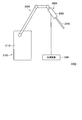
- FIG. 8 is a schematic diagram showing an example in which a rod integrator 400a is used as the radiation angle conversion element 400.
- the lens 300 for collimating the narrow band light is provided.
- a lens 302 for condensing the narrow band light on the rod integrator 400a is provided.
- the rod integrator 400a is made of, for example, a transparent glass material, and has a prismatic shape instead of a cylindrical shape.
- the narrow-band light that has entered the rod integrator 400a repeats total reflection in the rod integrator 400a, and exits from the end face opposite to the end face on which the light enters.
- NFP Near ⁇ Field ⁇ Pattern
- FFP Fluor ⁇ Field ⁇ Pattern
- the emission angle distribution of the narrow band light is converted and narrowed as shown in FIG.
- the emission angle of the band light can be widened.
- the light emitted from the rod integrator 400a is collimated by the lens 304, passes through the dichroic mirror 310 for multiplexing, and is focused on the light guide 500 by the lens 320.
- FIG. 9 and FIG. 10 are schematic diagrams showing a method of limiting the NA of broadband light by an aperture.
- an aperture 340 is provided on the front side of the lens 330 (on the broadband light source 200 side).
- an aperture 340 is provided behind the lens 330 (on the dichroic mirror 310 side).
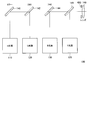
- FIG. 11 is a schematic diagram illustrating an example of a narrow-band light source 100 that combines narrow-band light from a plurality of wavelengths.
- the narrowband light source 100 includes a red light source 110, a green light source 120, a blue light source 130, a mirror 140, a dichroic mirror (DM1) 142, a dichroic mirror (DM2) 144, and a condenser lens 146. It is configured.
- Each of the red light source 110, the green light source 120, and the blue light source 130 is constituted by a semiconductor laser and is driven independently.
- a GaInP quantum well structure laser diode (RLD) is used as the red light source 110
- a GaInN quantum well structure laser diode (GLD) is used as the green light source 120
- a GaInN quantum well structure laser diode (BLD) is used as the blue light source 130.
- the red light emitted from the red light source 110 is reflected by the mirror 140 at an angle of 45 °, passes through the dichroic mirror 142 and the dichroic mirror 144, and is collected by the condenser lens 146.
- the green light emitted from the green light source 120 is emitted toward the dichroic mirror 142, and the blue light emitted from the blue light source 130 is emitted toward the dichroic mirror 144.
- the dichroic mirror 142 has an optical characteristic of transmitting a red wavelength and reflecting a green wavelength.
- the dichroic mirror 144 has optical characteristics of transmitting a red wavelength and a green wavelength and reflecting a blue wavelength.
- the red wavelength from the red light source 110 is combined with the green wavelength from the green light source 120 by the dichroic mirror 142 and combined with the blue wavelength from the blue light source 130 by the dichroic mirror 144.
- the combined light is condensed by the condenser lens 146. As described above, by combining the red wavelength, the green wavelength, and the blue wavelength, a white light laser can be emitted from the narrowband light source 100.
- FIG. 12 is a schematic diagram showing a configuration example in which a yellow light source 135, a dichroic mirror 145, and an aperture 430 are added to the narrow band light source 100 shown in FIG.
- the yellow light source 135 is composed of a semiconductor laser.
- the red wavelength from the red light source 110 is multiplexed with the green wavelength from the green light source 120 by the dichroic mirror 142, multiplexed with the blue wavelength from the blue light source 130 by the dichroic mirror 144, and the yellow light source by the dichroic mirror 145. Combines with yellow wavelength from 135. Therefore, according to the configuration example shown in FIG.
- the light source device 1000 can be configured only with the narrow band light source 100 without providing the broad band light source 200 as shown in FIG.
- the emission angles of the red, green, blue, and yellow laser beams emitted from the red light source 110, the green light source 120, the blue light source 130, and the yellow light source 135 all have a Gaussian distribution. Have. Therefore, according to the configuration example shown in FIG. 12, unlike the case where the narrow-band light and the wide-band light are multiplexed, the distribution of the emission angles of the respective colors is uniform, so that the white light after the multiplexing does not have unevenness.
- FIG. 13 is a diagram illustrating an example of a schematic configuration of an endoscope operation system 3000 to which the light source device 1000 according to the present disclosure may be applied.
- the endoscope operation system 3000 includes an endoscope 2000, a support arm device 2100 that supports the endoscope 2000, and a light source device 1000.
- the support arm device 2100 includes an arm 2020 extending from the base 2110.
- the arm unit 2020 includes a plurality of joints and a plurality of links, and is driven by control from an arm control device.
- the endoscope 2000 is supported by the arm 2020, and its position and posture are controlled. Thereby, stable fixing of the position of the endoscope 2000 can be realized.
- the endoscope 2000 includes a lens barrel 2010 having a region of a predetermined length from the distal end inserted into a body cavity of a patient, and a camera head 2020 connected to a proximal end of the lens barrel 2010.
- the endoscope 2000 may be configured as a so-called rigid scope having a hard barrel 2010, or may be configured as a so-called flexible scope having a soft barrel 2010.
- An opening in which the objective lens (observation optical system 600) is fitted is provided at the tip of the lens barrel 2010.
- a light source device 1000 is connected to the endoscope 2000, and light generated by the light source device 1000 is guided to the tip of the lens barrel 2010 by a light guide 500 extending inside the lens barrel 2010, and an objective is provided. The light is radiated toward the observation target in the body cavity of the patient via the lens.
- An optical system and an image sensor are provided inside the camera head 2020, and the reflected light (observation light) from the observation target is focused on the image sensor by the optical system.
- the observation light is photoelectrically converted by the imaging element, and an electric signal corresponding to the observation light, that is, an image signal corresponding to an observation image is generated.
- the image signal is transmitted as RAW data to a camera control unit (CCU).
- the camera head 2020 has a function of adjusting the magnification and the focal length by appropriately driving the optical system.
- the camera head 2020 may be provided with a plurality of image sensors in order to support, for example, stereoscopic viewing (3D display).
- a plurality of relay optical systems are provided inside the lens barrel 2010 in order to guide observation light to each of the plurality of image sensors.
- FIG. 14 is a diagram illustrating an example of a schematic configuration of a microscope operation system 6000 to which the light source device 1000 according to the present disclosure may be applied.
- the microsurgery system 6000 includes a microscope device 4000 and a light source device 1000.
- the microscope device 4000 includes a microscope section 4010 for magnifying and observing an observation target (operated part of a patient), an arm section 4020 supporting the microscope section 4010 at the distal end, and a base section 4030 supporting the base end of the arm section 4020. And
- the microscope unit 4010 is a microscope unit of an electronic imaging type (a so-called video microscope unit) that electronically captures a captured image by an imaging unit.
- Light from the observation target (hereinafter, also referred to as observation light) enters an imaging unit inside the microscope unit 4010.
- the imaging unit includes an optical system that collects observation light, and an imaging device that receives the observation light collected by the optical system.
- the optical system is configured by combining a plurality of lenses including a zoom lens and a focus lens, and the optical characteristics thereof are adjusted so that the observation light forms an image on the light receiving surface of the image sensor.
- the imaging device receives the observation light and performs photoelectric conversion to generate a signal corresponding to the observation light, that is, an image signal corresponding to an observation image.
- an imaging device having a Bayer array and capable of performing color imaging is used.
- the image sensor may be any of various known image sensors such as a CMOS (Complementary Metal Oxide Semiconductor) image sensor or a CCD (Charge Coupled Device) image sensor.
- CMOS Complementary Metal Oxide Semiconductor
- CCD Charge Coupled Device
- the arm portion 4020 is configured by a plurality of links (first link 4022a to sixth link 4022f) being rotatably connected to each other by a plurality of joint portions (first joint portion 4024a to sixth joint portion 4024f). Is done. Each joint is rotatable about a rotation axis indicated by a chain line.
- the number and shape (length) of the links constituting the illustrated arm unit 4020, the number of joints, the arrangement position, the direction of the rotation axis, and the like are appropriately designed so as to realize desired degrees of freedom.
- the first joint portion 4024a to the sixth joint portion 4024f may be provided with a drive mechanism such as a motor and an actuator on which an encoder or the like for detecting a rotation angle at each joint portion is mounted. Then, by appropriately controlling the driving of the actuators provided in the first joint portion 4024a to the sixth joint portion 4024f, the attitude of the arm section 4020, that is, the position and the attitude of the microscope section 4000 can be controlled.
- the light source device 1000 is built in, for example, the inside of the base portion 4030.
- the light guide 500 connected to the light source device 1000 passes through the inside or outside of the first to sixth links 4022a to 4022f, and is guided to the microscope unit 4010.
- the brightness of the observation target is reduced when the imaging unit inside the microscope unit 4010 images the observation target (affected part) of the patient. In other words, the observation target can be clearly imaged.
- the present embodiment it is possible to make the radiation angle distribution shapes of the narrow-band light and the broad-band light closer by making the narrow-band light incident on the radiation angle conversion element 400, thereby reducing the unevenness of the irradiation light. can do. Further, by combining narrowband light with broadband light, color rendering properties can be improved. Thereby, when the narrow band light is generated by the semiconductor laser, it is possible to efficiently converge the illumination light, which has high color rendering properties and suppresses the occurrence of unevenness, to the small diameter light guide. In addition, by converting the emission angle of the narrowband light to match the emission angle distribution of the broadband light, it is possible to suppress a decrease in the amount of light in the peripheral portion.
- the medical light source device has been described as an example, but the present technology is not limited to such an example.
- the present embodiment can be applied to a widely used light source device such as an industrial light source device.
- a medical device including an imaging unit for imaging the observation target, A light source device that generates light for irradiating the observation target, With The light source device, A narrow-band light source that emits narrow-band light whose wavelength width is a narrow band, A broadband light source that emits broadband light whose wavelength width is wider than the narrowband light, A multiplexing unit that multiplexes the narrowband light and the wideband light, A radiation angle conversion unit that converts the radiation angle of the narrowband light, A medical system comprising: (2) A narrow-band light source that emits narrow-band light whose wavelength width is a narrow band, A broadband light source that emits broadband light whose wavelength width is wider than the narrowband light, A multiplexing unit that multiplexes the narrowband light and the wideband light, A radiation angle conversion unit that converts the radiation angle of the narrowband light, A medical light source device comprising: (3) The medical light source device according to (2), wherein the radiation angle conversion unit expands a radiation angle distribution
- the medical light source device (4) The medical light source device according to (3), wherein the radiation angle conversion unit widens the radiation angle distribution of the narrowband light to approximate the radiation angle distribution of the broadband light. (5) The medical light source device according to any one of (2) to (4), further including a lens that collimates the narrowband light incident on the radiation angle conversion unit. (6) The medical light source device according to any one of (2) to (5), wherein the radiation angle conversion unit includes a diffusion plate that diffuses the narrowband light. (7) The medical light source device according to any one of (2) to (5), wherein the radiation angle conversion unit includes a fly-eye lens. (8) The medical light source device according to any one of (2) to (5), wherein the radiation angle conversion unit includes a rod integrator.
- the medical light source device according to any one of (2) to (8), further including a radiation angle restricting unit that restricts a radiation angle of the broadband light.
- the medical light source device according to (9), wherein the radiation angle limiting unit includes a lens through which the broadband light passes.
- the radiation angle limiting unit includes an aperture through which the broadband light passes.
- the narrow band light source is constituted by a laser light source.
- the narrow band light source A red laser light source that generates red light, A green laser light source for producing green light, A blue laser light source that generates blue light,
- white light is emitted by combining the red light, the green light, and the blue light.
- a method in a medical light source device comprising:
Landscapes
- Health & Medical Sciences (AREA)
- Life Sciences & Earth Sciences (AREA)
- Surgery (AREA)
- Physics & Mathematics (AREA)
- Optics & Photonics (AREA)
- Engineering & Computer Science (AREA)
- Heart & Thoracic Surgery (AREA)
- Animal Behavior & Ethology (AREA)
- Pathology (AREA)
- Radiology & Medical Imaging (AREA)
- Biophysics (AREA)
- Biomedical Technology (AREA)
- Veterinary Medicine (AREA)
- Medical Informatics (AREA)
- Molecular Biology (AREA)
- Nuclear Medicine, Radiotherapy & Molecular Imaging (AREA)
- General Health & Medical Sciences (AREA)
- Public Health (AREA)
- General Physics & Mathematics (AREA)
- Signal Processing (AREA)
- Chemical & Material Sciences (AREA)
- Analytical Chemistry (AREA)
- Astronomy & Astrophysics (AREA)
- Endoscopes (AREA)
- Instruments For Viewing The Inside Of Hollow Bodies (AREA)
- Microscoopes, Condenser (AREA)
Abstract
The objective of the invention is to generate a light of high color rendering ability while suppressing the occurrence of unevenness. The present invention provides a medical system (3000, 6000) comprising a medical machine (2000, 4000) equipped with an imaging unit for imaging a part to be observed, and a light source device (1000) generating a light to be irradiated onto the part to be observed. The light source device comprises: a narrow band light source (100) that emits narrow band light whereof the wavelength width is a narrow band, a broad band light source (200) that emits broad band light whereof the wavelength width is a broader band than that of the narrow band light, a multiplexing unit (310) for multiplexing the narrow band light and the broad band light, and an emission angle conversion unit (400) converting the emission angle of the narrow band light.
Description
本開示は、医療用システム、医療用光源装置及び医療用光源装置における方法に関する。
The present disclosure relates to a medical system, a medical light source device, and a method in a medical light source device.
従来、例えば下記の特許文献1には、少なくとも1つのレーザ光源を備え、レーザ光源からの光をライトガイドに入射させることが記載されている。
Conventionally, for example, Patent Document 1 below describes that at least one laser light source is provided and light from the laser light source is incident on a light guide.
上記特許文献に記載されているような医療用の光源では、ランプ光源(キセノンランプやハロゲンランプ)や白色LEDなどが主に用いられている。しかし、これらの光源は、発光点のサイズが大きく、放射角が広いため、細径のライトガイドに効率よく集光させるのは困難である。
医療 In medical light sources as described in the above patent documents, lamp light sources (xenon lamps and halogen lamps), white LEDs, and the like are mainly used. However, these light sources have a large light emitting point size and a wide radiation angle, so that it is difficult to efficiently condense light on a small diameter light guide.
このため、発光点サイズが小さく放射角も狭い半導体レーザを用い、赤色光、緑色光、青色光を合波することで白色光を生成し、医療用の光源として用いることが考えられる。しかし、半導体レーザは波長幅が狭いため、例えば、赤色光、緑色光、青色光を合波して発生させた白色光は演色性が低下する。半導体レーザで生成した白色光の演色性を高めるため、半導体レーザで生成した白色光と他の光源から得られる白色光を合波すると、双方の白色光の放射角の相違により、白光の色合いがずれてしまい、ムラが生じる問題がある。これは、半導体レーザで生成した白色光の放射角分布がガウシアン形状をなすのに対して、他の光源(LEDなど)の白色光の放射角分布がランバーシアン形状をなすことに起因する。
Therefore, it is conceivable to use a semiconductor laser with a small emission point size and a narrow emission angle to combine red light, green light, and blue light to generate white light and use it as a medical light source. However, since a semiconductor laser has a narrow wavelength width, for example, white light generated by combining red light, green light, and blue light has low color rendering. When the white light generated by the semiconductor laser and white light obtained from another light source are combined to enhance the color rendering of the white light generated by the semiconductor laser, the color of the white light is changed due to the difference in the emission angle of both white lights. There is a problem that it shifts and causes unevenness. This is because the emission angle distribution of the white light generated by the semiconductor laser has a Gaussian shape, whereas the emission angle distribution of the white light of another light source (such as an LED) has a Lambertian shape.
特に、医療用の用途を想定した場合、演色性の低下、ムラなどが生じると、例えば患部の病巣、腫瘍などを色で判断する場合などにおいて、術者(医師)の診断に誤認が生じる可能性がある。また、中心部のみ演色性、ムラが確保されている画像の場合、術者が適正な判断を行うためには、内視鏡や顕微鏡などの機器を操作して患部を画像の中心に移動させる必要が生じ、非常に煩雑な操作が要求されることになる。
In particular, assuming a medical use, if the color rendering property is reduced or uneven, the operator (doctor) may misdiagnose the diagnosis, for example, when judging the lesion, tumor, etc. of the affected part by color. There is. In addition, in the case of an image in which color rendering properties and unevenness are secured only in the central portion, the operator moves an affected part to the center of the image by operating a device such as an endoscope or a microscope in order to make an appropriate determination. This necessitates a very complicated operation.
そこで、演色性の高い光を生成するとともに、ムラの発生を抑制することが求められていた。
Therefore, it has been required to generate light having high color rendering properties and to suppress the occurrence of unevenness.
本開示によれば、観察対象を撮像する撮像部を備える医療用機器と、前記観察対象に照射する光を生成する光源装置と、を備え、前記光源装置は、波長幅が狭帯域である狭帯域光を出射する狭帯域光源と、前記狭帯域光よりも前記波長幅が広帯域である広帯域光を出射する広帯域光源と、前記狭帯域光と前記広帯域光を合波する合波部と、前記狭帯域光の放射角を変換する放射角変換部と、を有する、医療用システムが提供される。
According to the present disclosure, a medical device including an imaging unit that captures an image of an observation target, and a light source device that generates light for irradiating the observation target, the light source device has a narrow wavelength band having a narrow band. A narrow-band light source that emits band light, a broad-band light source that emits broad-band light whose wavelength width is wider than the narrow-band light, a multiplexing unit that multiplexes the narrow-band light and the broad-band light, A medical system comprising: a radiation angle conversion unit that converts a radiation angle of narrowband light.
また、本開示によれば、波長幅が狭帯域である狭帯域光を出射する狭帯域光源と、前記狭帯域光よりも前記波長幅が広帯域である広帯域光を出射する広帯域光源と、前記狭帯域光と前記広帯域光を合波する合波部と、前記狭帯域光の放射角を変換する放射角変換部と、を備える、医療用光源装置が提供される。
Further, according to the present disclosure, a narrow-band light source that emits narrow-band light whose wavelength width is a narrow band, a broad-band light source that emits broad-band light whose wavelength width is wider than the narrow-band light, A medical light source device is provided, comprising: a multiplexing unit that multiplexes band light and the broadband light; and a radiation angle conversion unit that converts a radiation angle of the narrowband light.
また、本開示によれば、波長幅が狭帯域である狭帯域光と前記狭帯域光よりも前記波長幅が広帯域である広帯域光を合波することと、前記合波の前に前記狭帯域光の放射角を変換することと、を備える、医療用光源装置における方法が提供される。
Further, according to the present disclosure, the narrow-band light having a narrow wavelength band and the wide-band light having the wide wavelength band is wider than the narrow-band light, and the narrow-band light before the multiplexing, Converting the angle of emission of light, the method in a medical light source device.
本開示によれば、演色性の高い光を生成するとともに、ムラの発生を抑制することが可能となる。
なお、上記の効果は必ずしも限定的なものではなく、上記の効果とともに、または上記の効果に代えて、本明細書に示されたいずれかの効果、または本明細書から把握され得る他の効果が奏されてもよい。 According to the present disclosure, it is possible to generate light with high color rendering properties and to suppress the occurrence of unevenness.
Note that the above effects are not necessarily limited, and any of the effects shown in the present specification or other effects that can be grasped from the present specification are used together with or in place of the above effects. May be played.
以下に添付図面を参照しながら、本開示の好適な実施の形態について詳細に説明する。なお、本明細書及び図面において、実質的に同一の機能構成を有する構成要素については、同一の符号を付することにより重複説明を省略する。
Hereinafter, preferred embodiments of the present disclosure will be described in detail with reference to the accompanying drawings. In the specification and the drawings, components having substantially the same function and configuration are denoted by the same reference numerals, and redundant description is omitted.
なお、説明は以下の順序で行うものとする。
1.背景
2.光源装置の構成
3.放射角変換素子による放射角の変換
4.広帯域光のNA制限
5.放射角変換素子の例
6.広帯域光のNA制限の例
7.狭帯域光源の構成例
8.狭帯域光源が黄色光源を備える構成例
9.医療用システムの構成例
9.1.内視鏡システムの構成例
9.2.顕微鏡システムの構成例 The description will be made in the following order.
1. Background 2. 2. Configuration of light source device 3. Conversion of radiation angle by radiation angle conversion element 4. NA restriction of broadband light 5. Example of radiation angle conversion element 6. Example of NA restriction of broadband light 7. Configuration example of narrow band light source 8. Configuration example in which narrow-band light source includes yellow light source Configuration example of medical system 9.1. Configuration example of endoscope system 9.2. Configuration example of microscope system
1.背景
対象の内部構造を観察する装置として、内視鏡が広く普及している。特に医療の分野においては、内視鏡は、術式技術の発展に伴い急速に普及し、今では多くの診療分野で不可欠なものとなっている。近年、内視鏡装置は、軟性鏡・硬性鏡問わず、患者への低侵襲性が求められ、特に患者と直に触れるスコープ部分は細径化、小型化に向けて改良が重ねられている。これに伴い、患部を照らす照明装置としての光源装置は、より細いライトガイドに効率よく導光させることが課題となっている。従来の内視鏡装置の照明用光源は、ランプ光源(キセノンランプやハロゲンランプ)や白色LEDが主に用いられるが、どちらも発光点のサイズが大きく、放射角が広い(エタンデユーが大きい)ため、細径のライトガイドに効率よく集光させるのは困難であった。 1. BACKGROUND As a device for observing the internal structure of a target, an endoscope is widely used. Particularly in the medical field, endoscopes have rapidly spread with the development of surgical techniques and are now indispensable in many medical fields. In recent years, endoscope devices have been required to have low invasiveness to patients, regardless of whether they are flexible or rigid, and in particular, scopes that directly touch the patient have been continuously improved to reduce the diameter and size. . Along with this, a problem has arisen for a light source device as an illumination device for illuminating an affected part to efficiently guide light to a thinner light guide. Lamps (xenon lamps and halogen lamps) and white LEDs are mainly used as illumination light sources for conventional endoscope devices, but both have large emission points and large radiation angles (large etendue). It has been difficult to efficiently focus light on a small-diameter light guide.
対象の内部構造を観察する装置として、内視鏡が広く普及している。特に医療の分野においては、内視鏡は、術式技術の発展に伴い急速に普及し、今では多くの診療分野で不可欠なものとなっている。近年、内視鏡装置は、軟性鏡・硬性鏡問わず、患者への低侵襲性が求められ、特に患者と直に触れるスコープ部分は細径化、小型化に向けて改良が重ねられている。これに伴い、患部を照らす照明装置としての光源装置は、より細いライトガイドに効率よく導光させることが課題となっている。従来の内視鏡装置の照明用光源は、ランプ光源(キセノンランプやハロゲンランプ)や白色LEDが主に用いられるが、どちらも発光点のサイズが大きく、放射角が広い(エタンデユーが大きい)ため、細径のライトガイドに効率よく集光させるのは困難であった。 1. BACKGROUND As a device for observing the internal structure of a target, an endoscope is widely used. Particularly in the medical field, endoscopes have rapidly spread with the development of surgical techniques and are now indispensable in many medical fields. In recent years, endoscope devices have been required to have low invasiveness to patients, regardless of whether they are flexible or rigid, and in particular, scopes that directly touch the patient have been continuously improved to reduce the diameter and size. . Along with this, a problem has arisen for a light source device as an illumination device for illuminating an affected part to efficiently guide light to a thinner light guide. Lamps (xenon lamps and halogen lamps) and white LEDs are mainly used as illumination light sources for conventional endoscope devices, but both have large emission points and large radiation angles (large etendue). It has been difficult to efficiently focus light on a small-diameter light guide.
そこで、本実施形態では、発光点サイズが小さく放射角も狭い(エタンデユーが小さい)半導体レーザ(LD)を用いた光源装置を提案する。一方で、半導体レーザは波長幅が狭いため、例えば、赤色光、緑色光、青色光を合波して発生させた白色光は演色性が悪いことが一般的に知られている。演色性が悪化すると、例えば悪性腫瘍を判断する場合などにおいて、内視鏡観察による医師の診断に誤認が生じる可能性がある。そこで、本実施形態では、波長幅が広い光源を補助光源としてレーザ光に混色させ、演色性を向上させている。特に、赤色光、緑色光、青色光を合波して発生させた白色光は、これらの色の中間の波長の光がないため、波長幅が広い光源と混色することで、白色の色合いを最適にすることができ、演色性を向上できる。
Therefore, the present embodiment proposes a light source device using a semiconductor laser (LD) having a small light emitting point size and a narrow radiation angle (small etendue). On the other hand, since a semiconductor laser has a narrow wavelength width, it is generally known that, for example, white light generated by combining red light, green light, and blue light has poor color rendering properties. When the color rendering property is deteriorated, for example, when a malignant tumor is determined, there is a possibility that a doctor's diagnosis by endoscopic observation may be erroneously recognized. Therefore, in the present embodiment, a light source having a wide wavelength width is used as an auxiliary light source and mixed with laser light to improve color rendering. In particular, white light generated by combining red light, green light, and blue light does not have light with a wavelength in between these colors. It can be optimized and color rendering can be improved.
光源から光を導光するために光ファイバーをバンドルしたライトガイド(LG)は、一般的に入射した光の放射角度分布が保存された照明光を出射する。そのため、半導体レーザからの光をライトガイドに導光すると、レーザ光は一般的にガウシアン形状の放射角分布をもつため、光軸中心は明るく周辺部にいくほど暗くなる照明光となってしまう。
(4) A light guide (LG) in which an optical fiber is bundled to guide light from a light source generally emits illumination light in which a radiation angle distribution of incident light is preserved. For this reason, when light from a semiconductor laser is guided to a light guide, the laser light generally has a Gaussian-shaped emission angle distribution, so that the illumination light becomes brighter at the center of the optical axis and becomes darker toward the periphery.
一方、補助光源として用いる広帯域光(例えば、白色LED)は、一般的にランバーシアン形状の放射角分布を有するため、周辺部でも光量が落ちにくい照明光となる。この放射角分布の異なる二つの光を合波させると、中心部と周辺部で、レーザ光と広帯域光の割合がずれていくため、照明光にムラ(特に色ムラ)が生じてしまう。このため、レーザ光に白色LEDなどの補助光源を混色した際に、白色の色合いにずれが生じる。従って、レーザ光に白色LEDなどの補助光源を混色して演色性の高い光源を実現するためには、この照明光のムラを抑制する必要がある。例えば、中心よりも周辺でのムラが大きいと、医師が周辺を観察した際に誤認が生じやすくなる可能性がある。そこで、本実施形態では、照明光のムラを抑えるための光源装置を提案する。以下、詳細に説明する。
On the other hand, broadband light (for example, white LED) used as an auxiliary light source generally has a Lambertian radiation angle distribution, and therefore becomes illumination light in which the amount of light hardly decreases even in a peripheral portion. When two lights having different radiation angle distributions are combined, the ratio between the laser light and the broadband light is shifted between the central part and the peripheral part, so that unevenness (particularly color unevenness) occurs in the illumination light. For this reason, when the laser light is mixed with an auxiliary light source such as a white LED, the color of white is shifted. Therefore, in order to realize a light source having a high color rendering property by mixing a laser light with an auxiliary light source such as a white LED, it is necessary to suppress the unevenness of the illumination light. For example, if the unevenness is greater at the periphery than at the center, there is a possibility that a doctor may easily make a mistake when observing the periphery. Therefore, in the present embodiment, a light source device for suppressing unevenness of illumination light is proposed. The details will be described below.
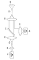
2.光源装置の構成
まず、図1を参照して、本開示の一実施形態に係る光源装置1000とその周辺の概略構成について説明する。本実施形態に係る光源装置1000は、図1に示すように、狭帯域光源100、広帯域光源200、レンズ300、レンズ305、ダイクロイックミラー(合波部)310、レンズ320、レンズ330、放射角度変換素子(放射角変換部)400を有して構成されている。光源装置1000から出射された光は、ライトガイド500を通り、観察光学系600に導光される。 2. Configuration of Light Source Device First, with reference to FIG. 1, a schematic configuration of alight source device 1000 according to an embodiment of the present disclosure and its periphery will be described. As shown in FIG. 1, the light source device 1000 according to the present embodiment includes a narrow band light source 100, a wide band light source 200, a lens 300, a lens 305, a dichroic mirror (combining unit) 310, a lens 320, a lens 330, and a radiation angle conversion. An element (radiation angle conversion unit) 400 is provided. The light emitted from the light source device 1000 passes through the light guide 500 and is guided to the observation optical system 600.
まず、図1を参照して、本開示の一実施形態に係る光源装置1000とその周辺の概略構成について説明する。本実施形態に係る光源装置1000は、図1に示すように、狭帯域光源100、広帯域光源200、レンズ300、レンズ305、ダイクロイックミラー(合波部)310、レンズ320、レンズ330、放射角度変換素子(放射角変換部)400を有して構成されている。光源装置1000から出射された光は、ライトガイド500を通り、観察光学系600に導光される。 2. Configuration of Light Source Device First, with reference to FIG. 1, a schematic configuration of a
狭帯域光源100は、半導体レーザから構成され、狭帯域光を出射する。広帯域光源200は白色LEDから構成され、白色の広帯域光を出射する。なお、広帯域光源200として白色LEDを例示するが、キセノンランプ、ハロゲンランプなどの光源であっても良い。また、広帯域光源200は、蛍光を発光する蛍光体であっても良い。
The narrow band light source 100 is composed of a semiconductor laser and emits narrow band light. The broadband light source 200 includes a white LED and emits white broadband light. Although a white LED is exemplified as the broadband light source 200, a light source such as a xenon lamp or a halogen lamp may be used. Further, the broadband light source 200 may be a phosphor that emits fluorescent light.
狭帯域光は、レンズ300でコリメートされ、放射角度変換素子400に入射される。放射角度変換素子400は、例えば拡散板を想定し、入射したコリメート光に所望の配光角をつける役割や放射角分布を変換する役割を担っている。放射角度変換素子400から出射された光は、レンズ305でコリメートされ、合波用のダイクロイックミラー310を透過して、レンズ320によってライトガイド500に集光される。
The narrow band light is collimated by the lens 300 and is incident on the radiation angle conversion element 400. The radiation angle conversion element 400 assumes a diffusion plate, for example, and plays a role of giving a desired light distribution angle to the incident collimated light and a role of converting the radiation angle distribution. Light emitted from the radiation angle conversion element 400 is collimated by a lens 305, passes through a dichroic mirror 310 for multiplexing, and is condensed on a light guide 500 by a lens 320.
一方、広帯域光は、レンズ330でコリメートされ、ダイクロイックミラー310で反射されて狭帯域光と合波し、レンズ320によってライトガイド500に集光される。
On the other hand, the broadband light is collimated by the lens 330, reflected by the dichroic mirror 310, combined with the narrowband light, and collected by the lens 320 on the light guide 500.
ダイクロイックミラー310は、狭帯域光の波長成分は透過し、それ以外の波長帯は反射するという特性を有する。ダイクロイックミラー310により、狭帯域光と広帯域光を合波することができる。なお、合波の手法として、波長合波、偏光合波、空間合波などの手法を用いることができる。
The dichroic mirror 310 has a characteristic that the wavelength component of the narrow band light is transmitted and the other wavelength band is reflected. The dichroic mirror 310 can combine narrowband light and broadband light. In addition, techniques such as wavelength multiplexing, polarization multiplexing, and spatial multiplexing can be used as the multiplexing technique.
ライトガイド500は、医療装置によく使われる数十μmのマルチモードファイバーをバンドルしたものを用いることができる。集光された照明光は、ライトガイド500を通して、観察光学系600に導光される。観察光学系600は、内視鏡用途であればスコープ内光学系、手術顕微鏡用途であれば顕微鏡光学系に当たり、光源装置1000から出射された光は、これらを通して実際の観察対象に照明光として照射される。
The light guide 500 can use a bundle of multi-mode fibers of several tens of μm often used in medical devices. The collected illumination light is guided to the observation optical system 600 through the light guide 500. The observation optical system 600 corresponds to an in-scope optical system for an endoscope application and a microscope optical system for an operation microscope application, and light emitted from the light source device 1000 irradiates an actual observation target as illumination light therethrough. Is done.
3.放射角変換素子による放射角の変換
図2は、狭帯域光の放射角分布を示す特性図である。図2において、横軸は放射角を、縦軸は光の強度を示している。狭帯域光は、放射角0度近傍の光の強度が高く、放射角に対する強度の分布がガウシアン分布となっている。 3. FIG. 2 is a characteristic diagram showing a radiation angle distribution of narrowband light. In FIG. 2, the horizontal axis represents the radiation angle, and the vertical axis represents the light intensity. In the narrowband light, the intensity of light near the radiation angle of 0 degree is high, and the distribution of the intensity with respect to the radiation angle is a Gaussian distribution.
図2は、狭帯域光の放射角分布を示す特性図である。図2において、横軸は放射角を、縦軸は光の強度を示している。狭帯域光は、放射角0度近傍の光の強度が高く、放射角に対する強度の分布がガウシアン分布となっている。 3. FIG. 2 is a characteristic diagram showing a radiation angle distribution of narrowband light. In FIG. 2, the horizontal axis represents the radiation angle, and the vertical axis represents the light intensity. In the narrowband light, the intensity of light near the radiation angle of 0 degree is high, and the distribution of the intensity with respect to the radiation angle is a Gaussian distribution.
図3は、広帯域光の放射角分布を示す特性図である。図3においても、横軸は放射角を、縦軸は光の強度を示している。広帯域光は、狭帯域光と比べて、放射角0度を中心とした光の強度の変化が少なく、放射角に対する光の強度の分布がランバーシアン分布となっている。
FIG. 3 is a characteristic diagram showing a radiation angle distribution of broadband light. Also in FIG. 3, the horizontal axis represents the radiation angle, and the vertical axis represents the light intensity. Broadband light has less change in light intensity centered on a radiation angle of 0 degrees than narrowband light, and the distribution of light intensity with respect to the radiation angle is a Lambertian distribution.
図4は、図2に示した狭帯域光の放射角分布と図3に示した広帯域光の放射角分布を重ねて示す特性図であり、狭帯域光と広帯域光をそのまま合波した状態を示している。図4に示すように、中心部付近(放射角0°)では広帯域光源と狭帯域光源の強度がほぼ同一であるが、周辺部になるほど狭帯域光源の強度の減少量が大きくなる。これは、中心部と周辺部で狭帯域光源と広帯域光源の強度比が異なっていくことを示しており、上述したムラが生じてしまう。
FIG. 4 is a characteristic diagram in which the emission angle distribution of the narrowband light shown in FIG. 2 and the emission angle distribution of the broadband light shown in FIG. 3 are superimposed, and shows a state where the narrowband light and the broadband light are multiplexed as they are. Is shown. As shown in FIG. 4, the intensity of the broadband light source and the intensity of the narrowband light source are almost the same near the center (radiation angle 0 °), but the intensity of the narrowband light source decreases more in the periphery. This indicates that the intensity ratio between the narrow band light source and the wide band light source is different between the central part and the peripheral part, and the above-described unevenness occurs.
このため、本実施形態では、狭帯域光を放射角度変換素子400に透過させ、狭帯域光の放射角分布を制御することで、広帯域光の放射角分布に近づけるようにしている。図5は、放射角度変換素子400を透過した後の狭帯域光の放射角分布を示す特性図である。図5に示すように、放射角度変換素子400を透過することで、狭帯域光の放射角分布が拡がり、狭帯域光の放射角分布は広帯域光の放射角分布に近似した特性となる。特に、レンズ300でコリメートした光を放射角度変換素子400に入射させることで、放射角度分布を所望の状態に変換することができ、放射角分布変化の効果を高めることができる。
For this reason, in the present embodiment, the narrow-band light is transmitted through the radiation angle conversion element 400, and the emission angle distribution of the narrow-band light is controlled so as to approximate the emission angle distribution of the wide-band light. FIG. 5 is a characteristic diagram showing a radiation angle distribution of the narrowband light transmitted through the radiation angle conversion element 400. As shown in FIG. 5, by transmitting through the radiation angle conversion element 400, the radiation angle distribution of the narrowband light expands, and the radiation angle distribution of the narrowband light has characteristics similar to the radiation angle distribution of the broadband light. In particular, by making the light collimated by the lens 300 incident on the radiation angle conversion element 400, the radiation angle distribution can be converted to a desired state, and the effect of changing the radiation angle distribution can be enhanced.
従って、放射角度変換素子400を透過した狭帯域光と広帯域光を合波することで、中心部から周辺部にかけて狭帯域光と広帯域光の強度の減少量が一致するため、中心部と周辺部で狭帯域光源と広帯域光源の強度比が一致する。これにより、ムラの発生を確実に抑制することが可能となる。
Therefore, by combining the narrowband light and the broadband light transmitted through the radiation angle conversion element 400, the reduction in the intensity of the narrowband light and the broadband light from the central portion to the peripheral portion coincides with each other. , The intensity ratio between the narrow band light source and the broad band light source matches. This makes it possible to reliably suppress the occurrence of unevenness.
4.広帯域光のNA制限
本実施形態では、広帯域光についてNA(Numerical Aperture)の制限を行う。NA制限は、図1に示すレンズ330のNAを広帯域光源の放射角より小さくすることで行う。なお、NAとは、最大受光角の大きさ(開口数)を正弦(sin)で表す数値である。図6は、図3に示す広帯域光にNA制限を行うことで、広帯域光の放射角分布を変化させた特性を示す特性図である。 4. NA Limitation of Broadband Light In the present embodiment, NA (Numerical Aperture) is limited for broadband light. The NA restriction is performed by making the NA of thelens 330 shown in FIG. 1 smaller than the radiation angle of the broadband light source. Note that NA is a numerical value representing the size (numerical aperture) of the maximum light receiving angle by a sine (sin). FIG. 6 is a characteristic diagram showing characteristics in which the emission angle distribution of the broadband light is changed by performing NA restriction on the broadband light shown in FIG.
本実施形態では、広帯域光についてNA(Numerical Aperture)の制限を行う。NA制限は、図1に示すレンズ330のNAを広帯域光源の放射角より小さくすることで行う。なお、NAとは、最大受光角の大きさ(開口数)を正弦(sin)で表す数値である。図6は、図3に示す広帯域光にNA制限を行うことで、広帯域光の放射角分布を変化させた特性を示す特性図である。 4. NA Limitation of Broadband Light In the present embodiment, NA (Numerical Aperture) is limited for broadband light. The NA restriction is performed by making the NA of the
図7は、図5に示した放射角度変換素子400を透過した狭帯域光の放射角分布と、図6に示したNA制限をかけた広帯域光の放射角分布を重ねて示す特性図であり、放射角度変換素子400を透過した狭帯域光とNA制限をかけた広帯域光を合波した状態を示している。
FIG. 7 is a characteristic diagram showing the emission angle distribution of the narrowband light transmitted through the emission angle conversion element 400 shown in FIG. 5 and the emission angle distribution of the broadband light subjected to NA limitation shown in FIG. 6 in an overlapping manner. 5 shows a state where narrow-band light transmitted through the radiation angle conversion element 400 and broad-band light subjected to NA restriction are combined.
このように、意図的にレンズ330のNAを小さくすることで、広帯域光の放射角の広い成分をカットすることができ、狭帯域光の放射角分布と広帯域光の放射角分布をより近似した特性にすることが可能となる。これにより、より確実にムラを抑制することが可能となる。
As described above, by intentionally reducing the NA of the lens 330, it is possible to cut a component having a wide emission angle of the broadband light, and more closely approximate the emission angle distribution of the narrowband light and the emission angle distribution of the broadband light. It becomes possible to make it characteristic. This makes it possible to more reliably suppress unevenness.
5.放射角変換素子の例
上述したように、放射角度変換素子400は、狭帯域光の放射角分布を変換し、狭帯域光の放射角を拡げる機能を有する。放射角度変換素子400として拡散板を用いることができる。拡散板を用いた場合、光学系を小型に構成できる、製造コストを低減できる、等のメリットが得られる。 5. Example of radiation angle conversion element As described above, the radiationangle conversion element 400 has a function of converting the emission angle distribution of narrowband light and expanding the emission angle of narrowband light. A diffusion plate can be used as the radiation angle conversion element 400. When a diffusion plate is used, advantages such as a compact optical system and a reduction in manufacturing cost can be obtained.
上述したように、放射角度変換素子400は、狭帯域光の放射角分布を変換し、狭帯域光の放射角を拡げる機能を有する。放射角度変換素子400として拡散板を用いることができる。拡散板を用いた場合、光学系を小型に構成できる、製造コストを低減できる、等のメリットが得られる。 5. Example of radiation angle conversion element As described above, the radiation
拡散板として、特にトップハット型拡散板を用いることが好適である。トップハット型拡散板を用いることで、図5に示したように、領域A1と領域A2でエッジが形成されたハット形状の特性を得ることができる。これにより、狭帯域光の周辺光量の低下を抑制することができ、狭帯域光と広帯域光の放射角分布を近づけることが可能である。
特 に It is particularly preferable to use a top hat type diffusion plate as the diffusion plate. By using the top hat diffusion plate, it is possible to obtain a hat-shaped characteristic in which edges are formed in the region A1 and the region A2, as shown in FIG. Accordingly, it is possible to suppress a decrease in the peripheral light amount of the narrow band light, and it is possible to make the radiation angle distributions of the narrow band light and the broad band light close.
また、放射角度変換素子400として、フライアイレンズを用いることもできる。フライアイレンズは入射光の角度の冗長性、マージンが広く、レンズ300による狭帯域光のコリメートの度合いを緩くしたとしても、放射角変換後の特性に対する影響が少ない。また、フライアイレンズを用いた場合、図5に示した領域A1,A2のエッジをよりシャープにすることができる。このため、例えば領域A1,A2のエッジまでを画像領域とする場合など、画像の領域をより広く確保したい場合は、フライアイレンズを用いることが好適である。
フ ラ イ Alternatively, a fly-eye lens can be used as the radiation angle conversion element 400. The fly-eye lens has a large angle redundancy and a large margin of incident light, and even if the degree of collimation of narrow-band light by the lens 300 is reduced, the effect on the characteristics after radiation angle conversion is small. When a fly-eye lens is used, the edges of the areas A1 and A2 shown in FIG. 5 can be sharpened. For this reason, it is preferable to use a fly-eye lens when it is necessary to secure a wider image area, for example, when an image area is formed up to the edges of the areas A1 and A2.
一方、フライアイレンズは通常2枚を1組として使用するため、光の透過率はトップハット型拡散板の方が高くなる。従って、光量をより確保したい場合などは、トップハット型拡散板を用いることが好適である。また、トップハット型拡散板を用いた場合の方が、低コスト化、省スペース化にも有利である。
On the other hand, since two fly-eye lenses are usually used as one set, the light transmittance of the top hat type diffusion plate is higher than that of the top hat type diffusion plate. Therefore, it is preferable to use a top-hat type diffusion plate when it is desired to secure more light quantity. In addition, the use of the top hat type diffusion plate is advantageous for cost reduction and space saving.
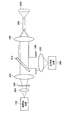
また、放射角度変換素子400として、ロッドインテグレータを用いることもできる。図8は、放射角度変換素子400としてロッドインテグレータ400aを用いた例を示す模式図である。図1では、狭帯域光をコリメートするレンズ300を設けていたが、図8では、狭帯域光をロッドインテグレータ400aに集光するレンズ302を設けている。放射角度変換素子400としてロッドインテグレータ400aを用いることで、光の透過効率をより高めることが可能である。
ロ ッ ド Also, a rod integrator can be used as the radiation angle conversion element 400. FIG. 8 is a schematic diagram showing an example in which a rod integrator 400a is used as the radiation angle conversion element 400. In FIG. 1, the lens 300 for collimating the narrow band light is provided. In FIG. 8, a lens 302 for condensing the narrow band light on the rod integrator 400a is provided. By using the rod integrator 400a as the radiation angle conversion element 400, it is possible to further enhance the light transmission efficiency.
ロッドインテグレータ400aは、例えば透明なガラス材から構成され、円柱形状ではなく角柱形状を成している。ロッドインテグレータ400aに入射した狭帯域光は、ロッドインテグレータ400a内で全反射を繰り返し、入射した側の端面とは反対側の端面から出射する。これにより、出射する端面全体に均一化したNFP(Near Field Pattern)となり、FFP(Far Field Pattern)にされたとき、狭帯域光の放射角分布が変換されて、図5に示したように狭帯域光の放射角を拡げることができる。ロッドインテグレータ400aから出射された光は、レンズ304でコリメートされ、合波用のダイクロイックミラー310を透過して、レンズ320によってライトガイド500に集光される。
The rod integrator 400a is made of, for example, a transparent glass material, and has a prismatic shape instead of a cylindrical shape. The narrow-band light that has entered the rod integrator 400a repeats total reflection in the rod integrator 400a, and exits from the end face opposite to the end face on which the light enters. As a result, NFP (Near \ Field \ Pattern) is made uniform over the entire exit facet, and when FFP (Far \ Field \ Pattern) is used, the emission angle distribution of the narrow band light is converted and narrowed as shown in FIG. The emission angle of the band light can be widened. The light emitted from the rod integrator 400a is collimated by the lens 304, passes through the dichroic mirror 310 for multiplexing, and is focused on the light guide 500 by the lens 320.
6.広帯域光のNA制限の例
上述したように、広帯域光のNAの制限は、レンズ330によって行うことができる。一方、レンズ330の前後にアパーチャを設けることで広帯域光のNA制限を行うこともできる。図9及び図10は、アパーチャにより広帯域光のNAに制限をかける手法を示す模式図である。図9に示す例では、レンズ330よりも前側(広帯域光源200側)にアパーチャ340を設けている。また、図10に示す例では、レンズ330よりも後側(ダイクロイックミラー310側)にアパーチャ340を設けている。このように、アパーチャを設けることで広帯域光のNA制限を行うことも可能である。これにより、レンズ330によりNA制限をかけた場合と同様に、図6に示した広帯域光の特性を得ることが可能となる。 6. Example of NA Limitation of Broadband Light As described above, the limitation of the NA of broadband light can be performed by thelens 330. On the other hand, by providing apertures before and after the lens 330, it is also possible to limit the NA of broadband light. FIG. 9 and FIG. 10 are schematic diagrams showing a method of limiting the NA of broadband light by an aperture. In the example illustrated in FIG. 9, an aperture 340 is provided on the front side of the lens 330 (on the broadband light source 200 side). In the example shown in FIG. 10, an aperture 340 is provided behind the lens 330 (on the dichroic mirror 310 side). As described above, it is also possible to limit the NA of broadband light by providing an aperture. This makes it possible to obtain the characteristics of the broadband light shown in FIG. 6 as in the case where the NA is limited by the lens 330.
上述したように、広帯域光のNAの制限は、レンズ330によって行うことができる。一方、レンズ330の前後にアパーチャを設けることで広帯域光のNA制限を行うこともできる。図9及び図10は、アパーチャにより広帯域光のNAに制限をかける手法を示す模式図である。図9に示す例では、レンズ330よりも前側(広帯域光源200側)にアパーチャ340を設けている。また、図10に示す例では、レンズ330よりも後側(ダイクロイックミラー310側)にアパーチャ340を設けている。このように、アパーチャを設けることで広帯域光のNA制限を行うことも可能である。これにより、レンズ330によりNA制限をかけた場合と同様に、図6に示した広帯域光の特性を得ることが可能となる。 6. Example of NA Limitation of Broadband Light As described above, the limitation of the NA of broadband light can be performed by the
7.狭帯域光源の構成例
狭帯域光は一つの波長だけでなく、複数の波長が合波された光であっても良い。図11は、狭帯域光を複数の波長から合波する狭帯域光源100の一例を示す模式図である。図11に示すように、狭帯域光源100は、赤色光源110、緑色光源120、青色光源130、ミラー140、ダイクロイックミラー(DM1)142、ダイクロイックミラー(DM2)144、集光レンズ146を有して構成されている。 7. Configuration Example of Narrow Band Light Source The narrow band light may be not only one wavelength but also light obtained by combining a plurality of wavelengths. FIG. 11 is a schematic diagram illustrating an example of a narrow-band light source 100 that combines narrow-band light from a plurality of wavelengths. As shown in FIG. 11, the narrowband light source 100 includes a red light source 110, a green light source 120, a blue light source 130, a mirror 140, a dichroic mirror (DM1) 142, a dichroic mirror (DM2) 144, and a condenser lens 146. It is configured.
狭帯域光は一つの波長だけでなく、複数の波長が合波された光であっても良い。図11は、狭帯域光を複数の波長から合波する狭帯域光源100の一例を示す模式図である。図11に示すように、狭帯域光源100は、赤色光源110、緑色光源120、青色光源130、ミラー140、ダイクロイックミラー(DM1)142、ダイクロイックミラー(DM2)144、集光レンズ146を有して構成されている。 7. Configuration Example of Narrow Band Light Source The narrow band light may be not only one wavelength but also light obtained by combining a plurality of wavelengths. FIG. 11 is a schematic diagram illustrating an example of a narrow-
赤色光源110、緑色光源120、青色光源130のそれぞれは、半導体レーザから構成され、独立して駆動される。例えば、赤色光源110としてはGaInP量子井戸構造レーザダイオード(RLD)、緑色光源120としてはGaInN量子井戸構造レーザダイオード(GLD)、青色光源130としては、GaInN量子井戸構造レーザダイオード(BLD)が用いられる。
Each of the red light source 110, the green light source 120, and the blue light source 130 is constituted by a semiconductor laser and is driven independently. For example, a GaInP quantum well structure laser diode (RLD) is used as the red light source 110, a GaInN quantum well structure laser diode (GLD) is used as the green light source 120, and a GaInN quantum well structure laser diode (BLD) is used as the blue light source 130. .
赤色光源110から出射された赤色光はミラー140にて45°の角度で反射し、ダイクロイックミラー142、ダイクロイックミラー144を透過して集光レンズ146で集光される。緑色光源120から出射された緑色光は、ダイクロイックミラー142に向けて出射され、青色光源130から出射された青色光は、ダイクロイックミラー144に向けて出射される。
赤色 The red light emitted from the red light source 110 is reflected by the mirror 140 at an angle of 45 °, passes through the dichroic mirror 142 and the dichroic mirror 144, and is collected by the condenser lens 146. The green light emitted from the green light source 120 is emitted toward the dichroic mirror 142, and the blue light emitted from the blue light source 130 is emitted toward the dichroic mirror 144.
ダイクロイックミラー142は、赤色波長を透過し緑色波長を反射する光学特性を有している。ダイクロイックミラー144は、赤色波長、緑色波長を透過し、青色波長を反射する光学特性を有している。赤色光源110からの赤色波長は、ダイクロイックミラー142にて緑色光源120からの緑色波長と合波し、ダイクロイックミラー144にて青色光源130からの青色波長と合波する。合波された光は、集光レンズ146にて集光される。以上のようにして、赤色波長、緑色波長、青色波長が合波することで、狭帯域光源100から白色光のレーザを出射することができる。
The dichroic mirror 142 has an optical characteristic of transmitting a red wavelength and reflecting a green wavelength. The dichroic mirror 144 has optical characteristics of transmitting a red wavelength and a green wavelength and reflecting a blue wavelength. The red wavelength from the red light source 110 is combined with the green wavelength from the green light source 120 by the dichroic mirror 142 and combined with the blue wavelength from the blue light source 130 by the dichroic mirror 144. The combined light is condensed by the condenser lens 146. As described above, by combining the red wavelength, the green wavelength, and the blue wavelength, a white light laser can be emitted from the narrowband light source 100.
8.狭帯域光源が黄色光源を備える構成例
図12は、図11に示した狭帯域光源100に対し、黄色光源135、ダイクロイックミラー145、アパーチャ430を追加した構成例を示す模式図である。黄色光源135は、半導体レーザから構成される。赤色光源110からの赤色波長は、ダイクロイックミラー142にて緑色光源120からの緑色波長と合波し、ダイクロイックミラー144にて青色光源130からの青色波長と合波し、ダイクロイックミラー145にて黄色光源135からの黄色波長と合波する。従って、図12に示す構成例によれば、赤色波長、緑色波長、青色波長、黄色波長を合波することで、図11に示した狭帯域光源100よりも色合いが最適に調整された白色光を得ることができる。このため、図1に示したような広帯域光源200を特に設けることなく、狭帯域光源100のみで光源装置1000を構成することができる。 8. FIG. 12 is a schematic diagram showing a configuration example in which a yellowlight source 135, a dichroic mirror 145, and an aperture 430 are added to the narrow band light source 100 shown in FIG. The yellow light source 135 is composed of a semiconductor laser. The red wavelength from the red light source 110 is multiplexed with the green wavelength from the green light source 120 by the dichroic mirror 142, multiplexed with the blue wavelength from the blue light source 130 by the dichroic mirror 144, and the yellow light source by the dichroic mirror 145. Combines with yellow wavelength from 135. Therefore, according to the configuration example shown in FIG. 12, by combining the red wavelength, the green wavelength, the blue wavelength, and the yellow wavelength, white light whose hue is optimally adjusted compared to the narrowband light source 100 shown in FIG. Can be obtained. Therefore, the light source device 1000 can be configured only with the narrow band light source 100 without providing the broad band light source 200 as shown in FIG.
図12は、図11に示した狭帯域光源100に対し、黄色光源135、ダイクロイックミラー145、アパーチャ430を追加した構成例を示す模式図である。黄色光源135は、半導体レーザから構成される。赤色光源110からの赤色波長は、ダイクロイックミラー142にて緑色光源120からの緑色波長と合波し、ダイクロイックミラー144にて青色光源130からの青色波長と合波し、ダイクロイックミラー145にて黄色光源135からの黄色波長と合波する。従って、図12に示す構成例によれば、赤色波長、緑色波長、青色波長、黄色波長を合波することで、図11に示した狭帯域光源100よりも色合いが最適に調整された白色光を得ることができる。このため、図1に示したような広帯域光源200を特に設けることなく、狭帯域光源100のみで光源装置1000を構成することができる。 8. FIG. 12 is a schematic diagram showing a configuration example in which a yellow
また、図12に示す構成例によれば、赤色光源110、緑色光源120、青色光源130、黄色光源135から出射される赤色、緑色、青色、黄色のレーザ光の放射角は、全てガウシアン分布を有する。従って、図12に示す構成例によれば、狭帯域光と広帯域光を合波した場合と異なり、各色の放射角の分布が揃うため、合波後の白色光にムラは生じない。
Further, according to the configuration example shown in FIG. 12, the emission angles of the red, green, blue, and yellow laser beams emitted from the red light source 110, the green light source 120, the blue light source 130, and the yellow light source 135 all have a Gaussian distribution. Have. Therefore, according to the configuration example shown in FIG. 12, unlike the case where the narrow-band light and the wide-band light are multiplexed, the distribution of the emission angles of the respective colors is uniform, so that the white light after the multiplexing does not have unevenness.
一方、図12に示す構成例では、赤色、緑色、青色、黄色のレーザ光の放射角がガウシアン分布であるため、中心に対して周辺の光量が低下する。このため、図12に示すようなアパーチャ430を設け、周辺の光をカットすることで、照射範囲においてより均一な強度の白色光を生成することができる。従って、図12の構成によれば、ムラが抑制され、且つ均一な強度の白色光を出射することが可能となる。
On the other hand, in the configuration example shown in FIG. 12, since the emission angles of the red, green, blue, and yellow laser beams have a Gaussian distribution, the amount of light around the center decreases. For this reason, by providing an aperture 430 as shown in FIG. 12 and cutting off the surrounding light, it is possible to generate white light with more uniform intensity in the irradiation range. Therefore, according to the configuration of FIG. 12, it is possible to suppress unevenness and emit white light with uniform intensity.
また、図12に示す構成例では、アパーチャ430でNA制限を行うことにより、アパーチャ430の部分で発熱を生じさせることができる。従って、光源装置1000の外部のライトガイド500等が発熱することを抑制することが可能である。
In addition, in the configuration example shown in FIG. 12, by limiting the NA at the aperture 430, heat can be generated at the aperture 430. Therefore, it is possible to prevent the light guide 500 and the like outside the light source device 1000 from generating heat.
9.医療用システムの構成例
9.1.内視鏡システムの構成例
図13は、本開示に係る光源装置1000が適用され得る内視鏡手術システム3000の概略的な構成の一例を示す図である。内視鏡手術システム3000は、内視鏡2000と、内視鏡2000を支持する支持アーム装置2100と、光源装置1000と、を有して構成される。 9. Configuration example of medical system 9.1. Configuration Example of Endoscope System FIG. 13 is a diagram illustrating an example of a schematic configuration of anendoscope operation system 3000 to which the light source device 1000 according to the present disclosure may be applied. The endoscope operation system 3000 includes an endoscope 2000, a support arm device 2100 that supports the endoscope 2000, and a light source device 1000.
9.1.内視鏡システムの構成例
図13は、本開示に係る光源装置1000が適用され得る内視鏡手術システム3000の概略的な構成の一例を示す図である。内視鏡手術システム3000は、内視鏡2000と、内視鏡2000を支持する支持アーム装置2100と、光源装置1000と、を有して構成される。 9. Configuration example of medical system 9.1. Configuration Example of Endoscope System FIG. 13 is a diagram illustrating an example of a schematic configuration of an
支持アーム装置2100は、ベース部2110から延伸するアーム部2020を備える。図示する例では、アーム部2020は、複数の関節部、及び複数のリンクから構成されており、アーム制御装置からの制御により駆動される。アーム部2020によって内視鏡2000が支持され、その位置及び姿勢が制御される。これにより、内視鏡2000の安定的な位置の固定が実現され得る。
The support arm device 2100 includes an arm 2020 extending from the base 2110. In the illustrated example, the arm unit 2020 includes a plurality of joints and a plurality of links, and is driven by control from an arm control device. The endoscope 2000 is supported by the arm 2020, and its position and posture are controlled. Thereby, stable fixing of the position of the endoscope 2000 can be realized.
内視鏡2000は、先端から所定の長さの領域が患者の体腔内に挿入される鏡筒2010と、鏡筒2010の基端に接続されるカメラヘッド2020と、から構成される。内視鏡2000は、硬性の鏡筒2010を有するいわゆる硬性鏡として構成されても良いし、軟性の鏡筒2010を有するいわゆる軟性鏡として構成されてもよい。
The endoscope 2000 includes a lens barrel 2010 having a region of a predetermined length from the distal end inserted into a body cavity of a patient, and a camera head 2020 connected to a proximal end of the lens barrel 2010. The endoscope 2000 may be configured as a so-called rigid scope having a hard barrel 2010, or may be configured as a so-called flexible scope having a soft barrel 2010.
鏡筒2010の先端には、対物レンズ(観察光学系600)が嵌め込まれた開口部が設けられている。内視鏡2000には光源装置1000が接続されており、光源装置1000によって生成された光が、鏡筒2010の内部に延設されるライトガイド500によって鏡筒2010の先端まで導光され、対物レンズを介して患者の体腔内の観察対象に向かって照射される。
開口 An opening in which the objective lens (observation optical system 600) is fitted is provided at the tip of the lens barrel 2010. A light source device 1000 is connected to the endoscope 2000, and light generated by the light source device 1000 is guided to the tip of the lens barrel 2010 by a light guide 500 extending inside the lens barrel 2010, and an objective is provided. The light is radiated toward the observation target in the body cavity of the patient via the lens.
カメラヘッド2020の内部には光学系及び撮像素子が設けられており、観察対象からの反射光(観察光)は当該光学系によって当該撮像素子に集光される。当該撮像素子によって観察光が光電変換され、観察光に対応する電気信号、すなわち観察像に対応する画像信号が生成される。当該画像信号は、RAWデータとしてカメラコントロールユニット(CCU:Camera Control Unit)に送信される。なお、カメラヘッド2020には、その光学系を適宜駆動させることにより、倍率及び焦点距離を調整する機能が搭載される。
光学 An optical system and an image sensor are provided inside the camera head 2020, and the reflected light (observation light) from the observation target is focused on the image sensor by the optical system. The observation light is photoelectrically converted by the imaging element, and an electric signal corresponding to the observation light, that is, an image signal corresponding to an observation image is generated. The image signal is transmitted as RAW data to a camera control unit (CCU). The camera head 2020 has a function of adjusting the magnification and the focal length by appropriately driving the optical system.
なお、例えば立体視(3D表示)等に対応するために、カメラヘッド2020には撮像素子が複数設けられてもよい。この場合、鏡筒2010の内部には、当該複数の撮像素子のそれぞれに観察光を導光するために、リレー光学系が複数系統設けられる。
Note that the camera head 2020 may be provided with a plurality of image sensors in order to support, for example, stereoscopic viewing (3D display). In this case, a plurality of relay optical systems are provided inside the lens barrel 2010 in order to guide observation light to each of the plurality of image sensors.
9.2.顕微鏡システムの構成例
図14は、本開示に係る光源装置1000が適用され得る顕微鏡手術システム6000の概略的な構成の一例を示す図である。図14を参照すると、顕微鏡手術システム6000は、顕微鏡装置4000と、光源装置1000と、を有してから構成される。 9.2. Configuration Example of Microscope System FIG. 14 is a diagram illustrating an example of a schematic configuration of amicroscope operation system 6000 to which the light source device 1000 according to the present disclosure may be applied. Referring to FIG. 14, the microsurgery system 6000 includes a microscope device 4000 and a light source device 1000.
図14は、本開示に係る光源装置1000が適用され得る顕微鏡手術システム6000の概略的な構成の一例を示す図である。図14を参照すると、顕微鏡手術システム6000は、顕微鏡装置4000と、光源装置1000と、を有してから構成される。 9.2. Configuration Example of Microscope System FIG. 14 is a diagram illustrating an example of a schematic configuration of a
顕微鏡装置4000は、観察対象(患者の術部)を拡大観察するための顕微鏡部4010と、顕微鏡部4010を先端で支持するアーム部4020と、アーム部4020の基端を支持するベース部4030と、を有する。
The microscope device 4000 includes a microscope section 4010 for magnifying and observing an observation target (operated part of a patient), an arm section 4020 supporting the microscope section 4010 at the distal end, and a base section 4030 supporting the base end of the arm section 4020. And
顕微鏡部4010は、撮像部によって電子的に撮像画像を撮像する、電子撮像式の顕微鏡部(いわゆるビデオ式の顕微鏡部)である。観察対象からの光(以下、観察光ともいう)は、顕微鏡部4010の内部の撮像部に入射する。
The microscope unit 4010 is a microscope unit of an electronic imaging type (a so-called video microscope unit) that electronically captures a captured image by an imaging unit. Light from the observation target (hereinafter, also referred to as observation light) enters an imaging unit inside the microscope unit 4010.
撮像部は、観察光を集光する光学系と、当該光学系が集光した観察光を受光する撮像素子と、から構成される。当該光学系は、ズームレンズ及びフォーカスレンズを含む複数のレンズが組み合わされて構成され、その光学特性は、観察光を撮像素子の受光面上に結像するように調整されている。当該撮像素子は、観察光を受光して光電変換することにより、観察光に対応した信号、すなわち観察像に対応した画像信号を生成する。当該撮像素子としては、例えばBayer配列を有するカラー撮影可能なものが用いられる。当該撮像素子は、CMOS(Complementary Metal Oxide Semiconductor)イメージセンサ又はCCD(Charge Coupled Device)イメージセンサ等、各種の公知の撮像素子であってよい。
(4) The imaging unit includes an optical system that collects observation light, and an imaging device that receives the observation light collected by the optical system. The optical system is configured by combining a plurality of lenses including a zoom lens and a focus lens, and the optical characteristics thereof are adjusted so that the observation light forms an image on the light receiving surface of the image sensor. The imaging device receives the observation light and performs photoelectric conversion to generate a signal corresponding to the observation light, that is, an image signal corresponding to an observation image. As the imaging device, for example, an imaging device having a Bayer array and capable of performing color imaging is used. The image sensor may be any of various known image sensors such as a CMOS (Complementary Metal Oxide Semiconductor) image sensor or a CCD (Charge Coupled Device) image sensor.
アーム部4020は、複数のリンク(第1リンク4022a~第6リンク4022f)が、複数の関節部(第1関節部4024a~第6関節部4024f)によって互いに回動可能に連結されることによって構成される。各関節部は一点鎖線で示す回転軸を中心として回動可能とされている。
The arm portion 4020 is configured by a plurality of links (first link 4022a to sixth link 4022f) being rotatably connected to each other by a plurality of joint portions (first joint portion 4024a to sixth joint portion 4024f). Is done. Each joint is rotatable about a rotation axis indicated by a chain line.
なお、図示するアーム部4020を構成するリンクの数及び形状(長さ)、並びに関節部の数、配置位置及び回転軸の方向等は、所望の自由度が実現され得るように適宜設計されてよい。また、第1関節部4024a~第6関節部4024fには、モータ等の駆動機構、及び各関節部における回転角度を検出するエンコーダ等が搭載されたアクチュエータが設けられていても良い。そして、第1関節部4024a~第6関節部4024fに設けられる各アクチュエータの駆動が適宜制御されることにより、アーム部4020の姿勢、すなわち顕微鏡部4000の位置及び姿勢が制御され得る。
The number and shape (length) of the links constituting the illustrated arm unit 4020, the number of joints, the arrangement position, the direction of the rotation axis, and the like are appropriately designed so as to realize desired degrees of freedom. Good. Further, the first joint portion 4024a to the sixth joint portion 4024f may be provided with a drive mechanism such as a motor and an actuator on which an encoder or the like for detecting a rotation angle at each joint portion is mounted. Then, by appropriately controlling the driving of the actuators provided in the first joint portion 4024a to the sixth joint portion 4024f, the attitude of the arm section 4020, that is, the position and the attitude of the microscope section 4000 can be controlled.
光源装置1000は、例えばベース部4030の内部に内蔵されている。光源装置1000に接続されたライトガイド500は、第1リンク4022a~第6リンク4022fの内側、あるいは外側を通り、顕微鏡部4010に導かれる。顕微鏡部4010に導かれたライトガイド500の先端から観察対象に光を照射することで、顕微鏡部4010の内部の撮像部が患者の観察対象(患部)を撮像した際に、観察対象の輝度を高め、観察対象を鮮明に撮像することができる。
The light source device 1000 is built in, for example, the inside of the base portion 4030. The light guide 500 connected to the light source device 1000 passes through the inside or outside of the first to sixth links 4022a to 4022f, and is guided to the microscope unit 4010. By irradiating the observation target with light from the tip of the light guide 500 guided to the microscope unit 4010, the brightness of the observation target is reduced when the imaging unit inside the microscope unit 4010 images the observation target (affected part) of the patient. In other words, the observation target can be clearly imaged.
以上説明したように本実施形態によれば、狭帯域光を放射角度変換素子400に入射させることで、狭帯域光と広帯域光の放射角分布形状を近づけることができ、照射光のムラを低減することができる。また、狭帯域光に広帯域光を合波することで、演色性を向上することができる。これにより、狭帯域光を半導体レーザで生成した場合に、演色性が高くムラの発生が抑制された照明光を細径のライトガイドに効率よく集光させることができる。また、狭帯域光の放射角を変換して広帯域光の放射角分布に合わせることで、周辺部での光量の低下を抑制することが可能となる。
As described above, according to the present embodiment, it is possible to make the radiation angle distribution shapes of the narrow-band light and the broad-band light closer by making the narrow-band light incident on the radiation angle conversion element 400, thereby reducing the unevenness of the irradiation light. can do. Further, by combining narrowband light with broadband light, color rendering properties can be improved. Thereby, when the narrow band light is generated by the semiconductor laser, it is possible to efficiently converge the illumination light, which has high color rendering properties and suppresses the occurrence of unevenness, to the small diameter light guide. In addition, by converting the emission angle of the narrowband light to match the emission angle distribution of the broadband light, it is possible to suppress a decrease in the amount of light in the peripheral portion.
以上、添付図面を参照しながら本開示の好適な実施形態について詳細に説明したが、本開示の技術的範囲はかかる例に限定されない。本開示の技術分野における通常の知識を有する者であれば、請求の範囲に記載された技術的思想の範疇内において、各種の変更例または修正例に想到し得ることは明らかであり、これらについても、当然に本開示の技術的範囲に属するものと了解される。
Although the preferred embodiments of the present disclosure have been described above in detail with reference to the accompanying drawings, the technical scope of the present disclosure is not limited to such examples. It is apparent that a person having ordinary knowledge in the technical field of the present disclosure can come up with various changes or modifications within the scope of the technical idea described in the claims. Is naturally understood to belong to the technical scope of the present disclosure.
例えば、上記実施形態では、医療用の光源装置を例に挙げて説明したが、本技術はかかる例に限定されない。本実施形態は、例えば工業用の光源装置など、広く汎用的な光源装置に適用することが可能である。
For example, in the above embodiment, the medical light source device has been described as an example, but the present technology is not limited to such an example. The present embodiment can be applied to a widely used light source device such as an industrial light source device.
また、本明細書に記載された効果は、あくまで説明的または例示的なものであって限定的ではない。つまり、本開示に係る技術は、上記の効果とともに、または上記の効果に代えて、本明細書の記載から当業者には明らかな他の効果を奏しうる。
効果 In addition, the effects described in this specification are merely illustrative or exemplary, and not restrictive. That is, the technology according to the present disclosure can exhibit other effects that are obvious to those skilled in the art from the description in the present specification, in addition to or instead of the above effects.
なお、以下のような構成も本開示の技術的範囲に属する。
(1)
観察対象を撮像する撮像部を備える医療用機器と、
前記観察対象に照射する光を生成する光源装置と、
を備え、
前記光源装置は、
波長幅が狭帯域である狭帯域光を出射する狭帯域光源と、
前記狭帯域光よりも前記波長幅が広帯域である広帯域光を出射する広帯域光源と、
前記狭帯域光と前記広帯域光を合波する合波部と、
前記狭帯域光の放射角を変換する放射角変換部と、
を有する、医療用システム。
(2)
波長幅が狭帯域である狭帯域光を出射する狭帯域光源と、
前記狭帯域光よりも前記波長幅が広帯域である広帯域光を出射する広帯域光源と、
前記狭帯域光と前記広帯域光を合波する合波部と、
前記狭帯域光の放射角を変換する放射角変換部と、
を備える、医療用光源装置。
(3)
前記放射角変換部は、前記狭帯域光の放射角分布を拡げる、前記(2)に記載の医療用光源装置。
(4)
前記放射角変換部は、前記狭帯域光の放射角分布を拡げて前記広帯域光の放射角分布に近づける、前記(3)に記載の医療用光源装置。
(5)
前記放射角変換部に入射する前記狭帯域光をコリメートするレンズを備える、前記(2)~(4)のいずれかに記載の医療用光源装置。
(6)
前記放射角変換部は、前記狭帯域光を拡散させる拡散板から構成される、前記(2)~(5)のいずれかに記載の医療用光源装置。
(7)
前記放射角変換部は、フライアイレンズから構成される、前記(2)~(5)のいずれかに記載の医療用光源装置。
(8)
前記放射角変換部は、ロッドインテグレータから構成される、前記(2)~(5)のいずれかに記載の医療用光源装置。
(9)
前記広帯域光の放射角を制限する放射角制限部を更に備える、前記(2)~(8)のいずれかに記載の医療用光源装置。
(10)
前記放射角制限部は、前記広帯域光が通過するレンズから構成される、前記(9)に記載の医療用光源装置。
(11)
前記放射角制限部は、前記広帯域光が通過するアパーチャから構成される、前記(9)に記載の医療用光源装置。
(12)
前記狭帯域光源は、レーザ光源から構成される、前記(2)~(11)のいずれかに記載の医療用光源装置。
(13)
前記狭帯域光源は、
赤色光を生成する赤色レーザ光源と、
緑色光を生成する緑色レーザ光源と、
青色光を生成する青色レーザ光源と、
を備え、
前記赤色光、前記緑色光、及び前記青色光の合波により白色光を出射する、前記(12)に記載の医療用光源装置。
(14)
前記合波部により合波された前記狭帯域光及び前記広帯域光が照射されるライトガイドを備える、前記(2)~(13)のいずれかに記載の医療用光源装置。
(15)
前記合波部により合波された前記狭帯域光及び前記広帯域光が患者の観察対象に照射される、前記(2)~(14)のいずれかに記載の医療用光源装置。
(16)
波長幅が狭帯域である狭帯域光と前記狭帯域光よりも前記波長幅が広帯域である広帯域光を合波することと、
前記合波の前に前記狭帯域光の放射角を変換することと、
を備える、医療用光源装置における方法。 Note that the following configuration also belongs to the technical scope of the present disclosure.
(1)
A medical device including an imaging unit for imaging the observation target,
A light source device that generates light for irradiating the observation target,
With
The light source device,
A narrow-band light source that emits narrow-band light whose wavelength width is a narrow band,
A broadband light source that emits broadband light whose wavelength width is wider than the narrowband light,
A multiplexing unit that multiplexes the narrowband light and the wideband light,
A radiation angle conversion unit that converts the radiation angle of the narrowband light,
A medical system comprising:
(2)
A narrow-band light source that emits narrow-band light whose wavelength width is a narrow band,
A broadband light source that emits broadband light whose wavelength width is wider than the narrowband light,
A multiplexing unit that multiplexes the narrowband light and the wideband light,
A radiation angle conversion unit that converts the radiation angle of the narrowband light,
A medical light source device comprising:
(3)
The medical light source device according to (2), wherein the radiation angle conversion unit expands a radiation angle distribution of the narrowband light.
(4)
The medical light source device according to (3), wherein the radiation angle conversion unit widens the radiation angle distribution of the narrowband light to approximate the radiation angle distribution of the broadband light.
(5)
The medical light source device according to any one of (2) to (4), further including a lens that collimates the narrowband light incident on the radiation angle conversion unit.
(6)
The medical light source device according to any one of (2) to (5), wherein the radiation angle conversion unit includes a diffusion plate that diffuses the narrowband light.
(7)
The medical light source device according to any one of (2) to (5), wherein the radiation angle conversion unit includes a fly-eye lens.
(8)
The medical light source device according to any one of (2) to (5), wherein the radiation angle conversion unit includes a rod integrator.
(9)
The medical light source device according to any one of (2) to (8), further including a radiation angle restricting unit that restricts a radiation angle of the broadband light.
(10)
The medical light source device according to (9), wherein the radiation angle limiting unit includes a lens through which the broadband light passes.
(11)
The medical light source device according to (9), wherein the radiation angle limiting unit includes an aperture through which the broadband light passes.
(12)
The medical light source device according to any one of the above (2) to (11), wherein the narrow band light source is constituted by a laser light source.
(13)
The narrow band light source,
A red laser light source that generates red light,
A green laser light source for producing green light,
A blue laser light source that generates blue light,
With
The medical light source device according to (12), wherein white light is emitted by combining the red light, the green light, and the blue light.
(14)
The medical light source device according to any one of (2) to (13), further including a light guide that irradiates the narrowband light and the broadband light multiplexed by the multiplexing unit.
(15)
The medical light source device according to any one of (2) to (14), wherein the narrow-band light and the wide-band light combined by the combining unit are irradiated on an observation target of a patient.
(16)
Combining narrow-band light whose wavelength width is a narrow band and broad-band light whose wavelength width is wider than the narrow-band light,
Converting the emission angle of the narrowband light before the multiplexing;
A method in a medical light source device, comprising:
(1)
観察対象を撮像する撮像部を備える医療用機器と、
前記観察対象に照射する光を生成する光源装置と、
を備え、
前記光源装置は、
波長幅が狭帯域である狭帯域光を出射する狭帯域光源と、
前記狭帯域光よりも前記波長幅が広帯域である広帯域光を出射する広帯域光源と、
前記狭帯域光と前記広帯域光を合波する合波部と、
前記狭帯域光の放射角を変換する放射角変換部と、
を有する、医療用システム。
(2)
波長幅が狭帯域である狭帯域光を出射する狭帯域光源と、
前記狭帯域光よりも前記波長幅が広帯域である広帯域光を出射する広帯域光源と、
前記狭帯域光と前記広帯域光を合波する合波部と、
前記狭帯域光の放射角を変換する放射角変換部と、
を備える、医療用光源装置。
(3)
前記放射角変換部は、前記狭帯域光の放射角分布を拡げる、前記(2)に記載の医療用光源装置。
(4)
前記放射角変換部は、前記狭帯域光の放射角分布を拡げて前記広帯域光の放射角分布に近づける、前記(3)に記載の医療用光源装置。
(5)
前記放射角変換部に入射する前記狭帯域光をコリメートするレンズを備える、前記(2)~(4)のいずれかに記載の医療用光源装置。
(6)
前記放射角変換部は、前記狭帯域光を拡散させる拡散板から構成される、前記(2)~(5)のいずれかに記載の医療用光源装置。
(7)
前記放射角変換部は、フライアイレンズから構成される、前記(2)~(5)のいずれかに記載の医療用光源装置。
(8)
前記放射角変換部は、ロッドインテグレータから構成される、前記(2)~(5)のいずれかに記載の医療用光源装置。
(9)
前記広帯域光の放射角を制限する放射角制限部を更に備える、前記(2)~(8)のいずれかに記載の医療用光源装置。
(10)
前記放射角制限部は、前記広帯域光が通過するレンズから構成される、前記(9)に記載の医療用光源装置。
(11)
前記放射角制限部は、前記広帯域光が通過するアパーチャから構成される、前記(9)に記載の医療用光源装置。
(12)
前記狭帯域光源は、レーザ光源から構成される、前記(2)~(11)のいずれかに記載の医療用光源装置。
(13)
前記狭帯域光源は、
赤色光を生成する赤色レーザ光源と、
緑色光を生成する緑色レーザ光源と、
青色光を生成する青色レーザ光源と、
を備え、
前記赤色光、前記緑色光、及び前記青色光の合波により白色光を出射する、前記(12)に記載の医療用光源装置。
(14)
前記合波部により合波された前記狭帯域光及び前記広帯域光が照射されるライトガイドを備える、前記(2)~(13)のいずれかに記載の医療用光源装置。
(15)
前記合波部により合波された前記狭帯域光及び前記広帯域光が患者の観察対象に照射される、前記(2)~(14)のいずれかに記載の医療用光源装置。
(16)
波長幅が狭帯域である狭帯域光と前記狭帯域光よりも前記波長幅が広帯域である広帯域光を合波することと、
前記合波の前に前記狭帯域光の放射角を変換することと、
を備える、医療用光源装置における方法。 Note that the following configuration also belongs to the technical scope of the present disclosure.
(1)
A medical device including an imaging unit for imaging the observation target,
A light source device that generates light for irradiating the observation target,
With
The light source device,
A narrow-band light source that emits narrow-band light whose wavelength width is a narrow band,
A broadband light source that emits broadband light whose wavelength width is wider than the narrowband light,
A multiplexing unit that multiplexes the narrowband light and the wideband light,
A radiation angle conversion unit that converts the radiation angle of the narrowband light,
A medical system comprising:
(2)
A narrow-band light source that emits narrow-band light whose wavelength width is a narrow band,
A broadband light source that emits broadband light whose wavelength width is wider than the narrowband light,
A multiplexing unit that multiplexes the narrowband light and the wideband light,
A radiation angle conversion unit that converts the radiation angle of the narrowband light,
A medical light source device comprising:
(3)
The medical light source device according to (2), wherein the radiation angle conversion unit expands a radiation angle distribution of the narrowband light.
(4)
The medical light source device according to (3), wherein the radiation angle conversion unit widens the radiation angle distribution of the narrowband light to approximate the radiation angle distribution of the broadband light.
(5)
The medical light source device according to any one of (2) to (4), further including a lens that collimates the narrowband light incident on the radiation angle conversion unit.
(6)
The medical light source device according to any one of (2) to (5), wherein the radiation angle conversion unit includes a diffusion plate that diffuses the narrowband light.
(7)
The medical light source device according to any one of (2) to (5), wherein the radiation angle conversion unit includes a fly-eye lens.
(8)
The medical light source device according to any one of (2) to (5), wherein the radiation angle conversion unit includes a rod integrator.
(9)
The medical light source device according to any one of (2) to (8), further including a radiation angle restricting unit that restricts a radiation angle of the broadband light.
(10)
The medical light source device according to (9), wherein the radiation angle limiting unit includes a lens through which the broadband light passes.
(11)
The medical light source device according to (9), wherein the radiation angle limiting unit includes an aperture through which the broadband light passes.
(12)
The medical light source device according to any one of the above (2) to (11), wherein the narrow band light source is constituted by a laser light source.
(13)
The narrow band light source,
A red laser light source that generates red light,
A green laser light source for producing green light,
A blue laser light source that generates blue light,
With
The medical light source device according to (12), wherein white light is emitted by combining the red light, the green light, and the blue light.
(14)
The medical light source device according to any one of (2) to (13), further including a light guide that irradiates the narrowband light and the broadband light multiplexed by the multiplexing unit.
(15)
The medical light source device according to any one of (2) to (14), wherein the narrow-band light and the wide-band light combined by the combining unit are irradiated on an observation target of a patient.
(16)
Combining narrow-band light whose wavelength width is a narrow band and broad-band light whose wavelength width is wider than the narrow-band light,
Converting the emission angle of the narrowband light before the multiplexing;
A method in a medical light source device, comprising:
100 狭帯域光源
110 赤色光源
120 緑色光源
130 青色光源
200 広帯域光源
310 ダイクロイックミラー
330 レンズ
340,350 アパーチャ
400 放射角度変換素子
1000 光源装置
2000 内視鏡
3000 内視鏡手術システム
4000 顕微鏡装置
6000 顕微鏡手術システム DESCRIPTION OFSYMBOLS 100 Narrow band light source 110 Red light source 120 Green light source 130 Blue light source 200 Broadband light source 310 Dichroic mirror 330 Lens 340, 350 Aperture 400 Radiation angle conversion element 1000 Light source device 2000 Endoscope 3000 Endoscope operation system 4000 Microscope device 6000 Microscope operation system
110 赤色光源
120 緑色光源
130 青色光源
200 広帯域光源
310 ダイクロイックミラー
330 レンズ
340,350 アパーチャ
400 放射角度変換素子
1000 光源装置
2000 内視鏡
3000 内視鏡手術システム
4000 顕微鏡装置
6000 顕微鏡手術システム DESCRIPTION OF
Claims (16)
- 観察対象を撮像する撮像部を備える医療用機器と、
前記観察対象に照射する光を生成する光源装置と、
を備え、
前記光源装置は、
波長幅が狭帯域である狭帯域光を出射する狭帯域光源と、
前記狭帯域光よりも前記波長幅が広帯域である広帯域光を出射する広帯域光源と、
前記狭帯域光と前記広帯域光を合波する合波部と、
前記狭帯域光の放射角を変換する放射角変換部と、
を有する、医療用システム。 A medical device including an imaging unit for imaging the observation target,
A light source device that generates light for irradiating the observation target,
With
The light source device,
A narrow-band light source that emits narrow-band light whose wavelength width is a narrow band,
A broadband light source that emits broadband light whose wavelength width is wider than the narrowband light,
A multiplexing unit that multiplexes the narrowband light and the wideband light,
A radiation angle conversion unit that converts the radiation angle of the narrowband light,
A medical system comprising: - 波長幅が狭帯域である狭帯域光を出射する狭帯域光源と、
前記狭帯域光よりも前記波長幅が広帯域である広帯域光を出射する広帯域光源と、
前記狭帯域光と前記広帯域光を合波する合波部と、
前記狭帯域光の放射角を変換する放射角変換部と、
を備える、医療用光源装置。 A narrow-band light source that emits narrow-band light whose wavelength width is a narrow band,
A broadband light source that emits broadband light whose wavelength width is wider than the narrowband light,
A multiplexing unit that multiplexes the narrowband light and the wideband light,
A radiation angle conversion unit that converts the radiation angle of the narrowband light,
A medical light source device comprising: - 前記放射角変換部は、前記狭帯域光の放射角分布を拡げる、請求項2に記載の医療用光源装置。 The medical light source device according to claim 2, wherein the radiation angle conversion unit widens a radiation angle distribution of the narrowband light.
- 前記放射角変換部は、前記狭帯域光の放射角分布を拡げて前記広帯域光の放射角分布に近づける、請求項3に記載の医療用光源装置。 4. The medical light source device according to claim 3, wherein the radiation angle conversion unit widens the radiation angle distribution of the narrowband light to approximate the radiation angle distribution of the broadband light. 5.
- 前記放射角変換部に入射する前記狭帯域光をコリメートするレンズを備える、請求項2に記載の医療用光源装置。 The medical light source device according to claim 2, further comprising a lens that collimates the narrowband light incident on the radiation angle conversion unit.
- 前記放射角変換部は、前記狭帯域光を拡散させる拡散板から構成される、請求項2に記載の医療用光源装置。 The medical light source device according to claim 2, wherein the radiation angle conversion unit includes a diffusion plate that diffuses the narrowband light.
- 前記放射角変換部は、フライアイレンズから構成される、請求項2に記載の医療用光源装置。 The medical light source device according to claim 2, wherein the radiation angle conversion unit includes a fly-eye lens.
- 前記放射角変換部は、ロッドインテグレータから構成される、請求項2に記載の医療用光源装置。 The medical light source device according to claim 2, wherein the radiation angle conversion unit includes a rod integrator.
- 前記広帯域光の放射角を制限する放射角制限部を更に備える、請求項2に記載の医療用光源装置。 The medical light source device according to claim 2, further comprising a radiation angle limiting unit that restricts a radiation angle of the broadband light.
- 前記放射角制限部は、前記広帯域光が通過するレンズから構成される、請求項9に記載の医療用光源装置。 The medical light source device according to claim 9, wherein the radiation angle limiting unit includes a lens through which the broadband light passes.
- 前記放射角制限部は、前記広帯域光が通過するアパーチャから構成される、請求項9に記載の医療用光源装置。 The medical light source device according to claim 9, wherein the radiation angle limiting unit includes an aperture through which the broadband light passes.
- 前記狭帯域光源は、レーザ光源から構成される、請求項2に記載の医療用光源装置。 The medical light source device according to claim 2, wherein the narrow-band light source comprises a laser light source.
- 前記狭帯域光源は、
赤色光を生成する赤色レーザ光源と、
緑色光を生成する緑色レーザ光源と、
青色光を生成する青色レーザ光源と、
を備え、
前記赤色光、前記緑色光、及び前記青色光の合波により白色光を出射する、請求項12に記載の医療用光源装置。 The narrow band light source,
A red laser light source that generates red light,
A green laser light source for producing green light,
A blue laser light source that generates blue light,
With
The medical light source device according to claim 12, wherein white light is emitted by combining the red light, the green light, and the blue light. - 前記合波部により合波された前記狭帯域光及び前記広帯域光が照射されるライトガイドを備える、請求項2に記載の医療用光源装置。 The medical light source device according to claim 2, further comprising: a light guide that irradiates the narrowband light and the broadband light combined by the combining unit.
- 前記合波部により合波された前記狭帯域光及び前記広帯域光が患者の観察対象に照射される、請求項2に記載の医療用光源装置。 The medical light source device according to claim 2, wherein the narrow-band light and the wide-band light combined by the combining unit are applied to an observation target of a patient.
- 波長幅が狭帯域である狭帯域光と前記狭帯域光よりも前記波長幅が広帯域である広帯域光を合波することと、
前記合波の前に前記狭帯域光の放射角を変換することと、
を備える、医療用光源装置における方法。 Combining narrow-band light whose wavelength width is a narrow band and broad-band light whose wavelength width is wider than the narrow-band light,
Converting the emission angle of the narrowband light before the multiplexing;
A method in a medical light source device, comprising:
Priority Applications (4)
| Application Number | Priority Date | Filing Date | Title |
|---|---|---|---|
| US17/258,745 US20210267446A1 (en) | 2018-08-13 | 2019-08-07 | Medical system, medical light source apparatus, and method in medical light source apparatus |
| JP2020537432A JP7405080B2 (en) | 2018-08-13 | 2019-08-07 | Medical system, medical light source device, and operating method of medical light source device |
| EP19849589.7A EP3838110A4 (en) | 2018-08-13 | 2019-08-07 | Medical system, medical light source device and method for medical light source device |
| CN201980052301.XA CN112584748A (en) | 2018-08-13 | 2019-08-07 | Medical system, medical light source device and method in medical light source device |
Applications Claiming Priority (2)
| Application Number | Priority Date | Filing Date | Title |
|---|---|---|---|
| JP2018-152375 | 2018-08-13 | ||
| JP2018152375 | 2018-08-13 |
Publications (1)
| Publication Number | Publication Date |
|---|---|
| WO2020036112A1 true WO2020036112A1 (en) | 2020-02-20 |
Family
ID=69525521
Family Applications (1)
| Application Number | Title | Priority Date | Filing Date |
|---|---|---|---|
| PCT/JP2019/031277 WO2020036112A1 (en) | 2018-08-13 | 2019-08-07 | Medical system, medical light source device and method for medical light source device |
Country Status (5)
| Country | Link |
|---|---|
| US (1) | US20210267446A1 (en) |
| EP (1) | EP3838110A4 (en) |
| JP (1) | JP7405080B2 (en) |
| CN (1) | CN112584748A (en) |
| WO (1) | WO2020036112A1 (en) |
Cited By (1)
| Publication number | Priority date | Publication date | Assignee | Title |
|---|---|---|---|---|
| WO2023037932A1 (en) * | 2021-09-10 | 2023-03-16 | 株式会社Okファイバーテクノロジー | System for expanding irradiation range of laser light |
Families Citing this family (3)
| Publication number | Priority date | Publication date | Assignee | Title |
|---|---|---|---|---|
| CN115486816A (en) * | 2022-09-29 | 2022-12-20 | 衡阳市大井医疗器械科技有限公司 | LED white light and laser mixed medical light source assisting in distinguishing lesion position |
| CN116869460B (en) * | 2022-11-28 | 2024-07-02 | 上海澳华内镜股份有限公司 | Endoscope light source device |
| CN115561891B (en) * | 2022-11-29 | 2023-03-24 | 微创优通医疗科技(上海)有限公司 | Endoscope light source device and endoscope |
Citations (6)
| Publication number | Priority date | Publication date | Assignee | Title |
|---|---|---|---|---|
| JP2006006803A (en) * | 2004-06-29 | 2006-01-12 | Pentax Corp | Diaphragm controlling mechanism of electronic endoscope |
| JP2012075562A (en) * | 2010-09-30 | 2012-04-19 | Fujifilm Corp | Endoscope light source unit |
| JP2015223462A (en) | 2014-05-30 | 2015-12-14 | ソニー株式会社 | Lighting system, lighting method, and endoscope |
| WO2015194312A1 (en) * | 2014-06-17 | 2015-12-23 | オリンパス株式会社 | Endoscope light source device |
| JP2016120104A (en) * | 2014-12-25 | 2016-07-07 | ソニー株式会社 | Lighting device, lighting method, and observation device |
| JP2017187543A (en) * | 2016-04-01 | 2017-10-12 | ウシオ電機株式会社 | Light source device |
Family Cites Families (20)
| Publication number | Priority date | Publication date | Assignee | Title |
|---|---|---|---|---|
| US6404497B1 (en) * | 1999-01-25 | 2002-06-11 | Massachusetts Institute Of Technology | Polarized light scattering spectroscopy of tissue |
| JP2009536553A (en) * | 2006-05-08 | 2009-10-15 | ボストン サイエンティフィック リミテッド | Optical assembly for medical imaging devices |
| US7948172B2 (en) * | 2007-09-28 | 2011-05-24 | Global Oled Technology Llc | LED device having improved light output |
| US9028110B2 (en) * | 2009-07-17 | 2015-05-12 | The Commonwealth Of Australia | Visual warning device |
| CN103124514B (en) * | 2010-08-24 | 2016-09-28 | 欧司朗有限公司 | There is the color-tunable light source unit of unit and fluorescence unit |
| JP5612028B2 (en) * | 2012-07-02 | 2014-10-22 | 富士フイルム株式会社 | Light source device and endoscope system |
| JP5623469B2 (en) * | 2012-07-06 | 2014-11-12 | 富士フイルム株式会社 | ENDOSCOPE SYSTEM, ENDOSCOPE SYSTEM PROCESSOR DEVICE, AND ENDOSCOPE CONTROL PROGRAM |
| JP2015077335A (en) * | 2013-10-18 | 2015-04-23 | 三菱電機エンジニアリング株式会社 | Light source device |
| US10398294B2 (en) * | 2014-07-24 | 2019-09-03 | Z Square Ltd. | Illumination sources for multicore fiber endoscopes |
| JP6522647B2 (en) * | 2014-11-17 | 2019-05-29 | オリンパス株式会社 | Endoscope device |
| JP6394374B2 (en) * | 2014-12-25 | 2018-09-26 | ソニー株式会社 | Illumination apparatus, illumination method, and observation apparatus |
| EP3206560B1 (en) * | 2014-12-25 | 2024-06-12 | Sony Group Corporation | Medical imaging system and illumination device |
| JP2016137309A (en) * | 2016-04-22 | 2016-08-04 | 富士フイルム株式会社 | Light source device |
| KR102695988B1 (en) * | 2016-12-16 | 2024-08-16 | 한국전기연구원 | Optical imaging apparatus including wavelength converting light source and method for generating optical image using the same |
| JP7143320B2 (en) * | 2016-12-27 | 2022-09-28 | デピュイ・シンセス・プロダクツ・インコーポレイテッド | Systems, methods, and devices for providing illumination in an endoscopic imaging environment |
| US20190353890A1 (en) * | 2017-01-24 | 2019-11-21 | Sony Corporation | Light source apparatus, light amount distribution adjustment method, and image acquisition system |
| WO2019198293A1 (en) * | 2018-04-11 | 2019-10-17 | ソニー株式会社 | Microscope system and medical light source device |
| JP2020062326A (en) * | 2018-10-19 | 2020-04-23 | ソニー株式会社 | Medical system, light guide, and light multiplexing method |
| JP7071650B2 (en) * | 2019-06-19 | 2022-05-19 | 日亜化学工業株式会社 | Image acquisition device |
| CN111053523B (en) * | 2020-02-17 | 2022-04-22 | 青岛奥美克医疗科技有限公司 | Device of antifogging endoscope system |
-
2019
- 2019-08-07 CN CN201980052301.XA patent/CN112584748A/en active Pending
- 2019-08-07 EP EP19849589.7A patent/EP3838110A4/en active Pending
- 2019-08-07 JP JP2020537432A patent/JP7405080B2/en active Active
- 2019-08-07 US US17/258,745 patent/US20210267446A1/en active Pending
- 2019-08-07 WO PCT/JP2019/031277 patent/WO2020036112A1/en unknown
Patent Citations (6)
| Publication number | Priority date | Publication date | Assignee | Title |
|---|---|---|---|---|
| JP2006006803A (en) * | 2004-06-29 | 2006-01-12 | Pentax Corp | Diaphragm controlling mechanism of electronic endoscope |
| JP2012075562A (en) * | 2010-09-30 | 2012-04-19 | Fujifilm Corp | Endoscope light source unit |
| JP2015223462A (en) | 2014-05-30 | 2015-12-14 | ソニー株式会社 | Lighting system, lighting method, and endoscope |
| WO2015194312A1 (en) * | 2014-06-17 | 2015-12-23 | オリンパス株式会社 | Endoscope light source device |
| JP2016120104A (en) * | 2014-12-25 | 2016-07-07 | ソニー株式会社 | Lighting device, lighting method, and observation device |
| JP2017187543A (en) * | 2016-04-01 | 2017-10-12 | ウシオ電機株式会社 | Light source device |
Cited By (2)
| Publication number | Priority date | Publication date | Assignee | Title |
|---|---|---|---|---|
| WO2023037932A1 (en) * | 2021-09-10 | 2023-03-16 | 株式会社Okファイバーテクノロジー | System for expanding irradiation range of laser light |
| JP7309244B1 (en) * | 2021-09-10 | 2023-07-18 | 株式会社Okファイバーテクノロジー | A system for expanding the irradiation range of laser light |
Also Published As
| Publication number | Publication date |
|---|---|
| US20210267446A1 (en) | 2021-09-02 |
| JP7405080B2 (en) | 2023-12-26 |
| CN112584748A (en) | 2021-03-30 |
| JPWO2020036112A1 (en) | 2021-08-26 |
| EP3838110A4 (en) | 2021-09-08 |
| EP3838110A1 (en) | 2021-06-23 |
Similar Documents
| Publication | Publication Date | Title |
|---|---|---|
| JP7405080B2 (en) | Medical system, medical light source device, and operating method of medical light source device | |
| JP6965334B2 (en) | How to operate the camera in a minimally invasive surgical system | |
| US9025244B2 (en) | Illuminating system and an optical viewing apparatus incorporating said illuminating system | |
| US8699138B2 (en) | Multi-wavelength multi-lamp radiation sources and systems and apparatuses incorporating same | |
| JP4817632B2 (en) | LED fiber light source device and endoscope using the same | |
| JP2008514304A (en) | Solid state lighting for endoscopy | |
| JP6827512B2 (en) | Endoscope system | |
| JP2007311114A (en) | Lighting optical system using solid light emitting element emitting white light, and optical device equipped with it | |
| JP6099831B2 (en) | Light source device | |
| US11076106B2 (en) | Observation system and light source control apparatus | |
| US12042130B2 (en) | Light source and system for and method of fluorescence diagnosis | |
| EP3599983B1 (en) | Endoscopes | |
| WO2018003263A1 (en) | Observation device and control method for observation device | |
| JP6438830B2 (en) | Position adjustment method | |
| WO2020080223A1 (en) | Medical system, light guide and light multiplexing method | |
| WO2019198382A1 (en) | Medical system, medical light source device, and method for medical light source device | |
| WO2020071139A1 (en) | Medical observation system, medical light source device, and medical lighting method | |
| JP6359998B2 (en) | Endoscope | |
| JP6681454B2 (en) | Endoscope light source device and endoscope system | |
| JP2017136405A (en) | Endoscopic apparatus | |
| WO2024070980A1 (en) | Light source device and endoscope system | |
| JP2006122251A (en) | Led fiber light source device and endoscopic apparatus using the same | |
| JP7054401B2 (en) | Light source device for endoscopes | |
| JP2016137308A (en) | Endoscopic apparatus | |
| JP2022079732A (en) | Position adjustment method |
Legal Events
| Date | Code | Title | Description |
|---|---|---|---|
| 121 | Ep: the epo has been informed by wipo that ep was designated in this application |
Ref document number: 19849589 Country of ref document: EP Kind code of ref document: A1 |
|
| ENP | Entry into the national phase |
Ref document number: 2020537432 Country of ref document: JP Kind code of ref document: A |
|
| NENP | Non-entry into the national phase |
Ref country code: DE |
|
| ENP | Entry into the national phase |
Ref document number: 2019849589 Country of ref document: EP Effective date: 20210315 |