WO2020032704A1 - Method and device for performing synchronization procedure for nr v2x system - Google Patents
Method and device for performing synchronization procedure for nr v2x system Download PDFInfo
- Publication number
- WO2020032704A1 WO2020032704A1 PCT/KR2019/010102 KR2019010102W WO2020032704A1 WO 2020032704 A1 WO2020032704 A1 WO 2020032704A1 KR 2019010102 W KR2019010102 W KR 2019010102W WO 2020032704 A1 WO2020032704 A1 WO 2020032704A1
- Authority
- WO
- WIPO (PCT)
- Prior art keywords
- ssb
- terminal
- case
- information
- synchronization
- Prior art date
Links
Images


Classifications
-
- H—ELECTRICITY
- H04—ELECTRIC COMMUNICATION TECHNIQUE
- H04W—WIRELESS COMMUNICATION NETWORKS
- H04W56/00—Synchronisation arrangements
-
- H—ELECTRICITY
- H04—ELECTRIC COMMUNICATION TECHNIQUE
- H04W—WIRELESS COMMUNICATION NETWORKS
- H04W72/00—Local resource management
- H04W72/04—Wireless resource allocation
-
- H—ELECTRICITY
- H04—ELECTRIC COMMUNICATION TECHNIQUE
- H04W—WIRELESS COMMUNICATION NETWORKS
- H04W92/00—Interfaces specially adapted for wireless communication networks
- H04W92/16—Interfaces between hierarchically similar devices
- H04W92/18—Interfaces between hierarchically similar devices between terminal devices
Definitions
- the present invention relates to a synchronization signal transmission and reception method and a synchronization procedure for a NR (New Radio) Vehicle To Everything (V2X) system.
- NR New Radio
- V2X Vehicle To Everything
- the present invention relates to a method for setting a sidelink-synchronization signal block (SL-SSB) transmission resource for a NR (New Radio) Vehicle To Everything (V2X) system.
- SL-SSB sidelink-synchronization signal block
- V2X Vehicle To Everything
- the International Telecommunication Union (ITU) is developing the International Mobile Telecommunication (IMT) framework and standards, and is currently in discussions for 5G (5G) communication through a program called "IMT for 2020 and beyond.” .
- 3GPP 3rd Generation Partnership Project
- 3GPP 3rd Generation Partnership Project
- 3GPP New Radio
- V2X communication refers to a communication method of exchanging or sharing information such as traffic conditions while communicating with road infrastructure and other vehicles while driving.
- V2X is a vehicle-to-vehicle (V2V) that stands for Long Term Evolution (LTE) -based communication between vehicles, a vehicle-to-pedestrian (V2P) that stands for LTE-based communication between terminals carried by vehicles and individuals, and vehicles And vehicle-to-infrastructure / network (V2I / N), which means LTE-based communication between a roadside unit and a network.
- the roadside unit may be a transportation infrastructure entity implemented by a base station or a fixed terminal. For example, it may be an entity that transmits a speed notification to the vehicle.
- the present invention can provide a method of performing a synchronization procedure in an NR V2X system.
- the present invention can provide a method for selecting a synchronous reference source based on whether the NR V2X sidelink frequency of an NR V2X sidelink (SL) terminal is included in coverage on a network.
- the present invention can provide a method for selecting a synchronous reference source when the NR V2X sidelink frequency is In-Coverage (IC).
- IC In-Coverage
- the present invention can provide a method of selecting a synchronous reference source when the NR V2X sidelink frequency is out-of-coverage (OCC).
- OCC out-of-coverage
- the present invention can provide a method for configuring a SL-SSB transmission resource for an NR V2X system.
- the present invention can provide a method for configuring an SL-SSB transmission resource in terms of frequency domain.
- the present invention can provide a method for configuring an SL-SSB transmission resource from a time domain perspective.
- the present invention can provide a method for configuring an SL-SSB transmission resource in consideration of a relationship with a downlink-SSB (DL-SSB).
- DL-SSB downlink-SSB
- the present invention can provide a method for a UE to perform a synchronization procedure in an NR V2X system.
- the method of performing a synchronization procedure includes determining whether a frequency for V2X sidelink communication of a terminal is within coverage on a network, and selecting a synchronization reference source based on whether the frequency is within coverage on a network. can do.
- the present invention can provide a method for a UE to configure resources in an NR V2X system.
- the resource setting method may include the step of the terminal receiving the resource configuration information for the SL-SSB transmission from the base station and transmitting the SL-SSB based on the received resource configuration information.
- the resource configuration information for the SL-SSB transmission may include frequency position information for the SL-SBB and time position information for the SL-SSB.
- a method of performing a synchronization procedure in an NR V2X system may be provided.
- a method of selecting a synchronization reference source based on whether an NR V2X sidelink frequency of an NR V2X sidelink terminal is included in coverage on a network is not limited.
- a method of selecting a synchronization reference source may be provided.
- a method of selecting a synchronization reference source may be provided.
- DL-SSB downlink-SSB
- FIG. 1 is a diagram showing a frame structure for downlink / uplink transmission to which the present disclosure can be applied.
- FIG. 2 is a diagram illustrating a resource grid and a resource block to which the present disclosure may be applied.
- FIG. 3 is a diagram illustrating a synchronization signal transmission method according to an embodiment of the present invention.
- FIG. 4 illustrates a system architecture in accordance with an embodiment of the present invention.
- FIG. 5 is a diagram illustrating a method of transmitting a synchronization signal.
- FIG. 6 is a diagram illustrating a scenario in which NR V2X sidelink communication is performed in a 3GPP network.
- FIG. 7 is a diagram illustrating a method of selecting a synchronization reference source in incoverage.
- FIG. 8 illustrates a method of selecting a synchronous reference source in out of coverage.
- FIG 9 illustrates a scenario in which NR V2X sidelink communication is performed in a 3GPP network according to an embodiment of the present invention.
- FIG. 10 is a diagram illustrating a BWP configuration associated with a cell connection of an NR Uu link according to an embodiment of the present invention.
- FIG. 11 illustrates a relationship between a resource pool and a SLSS / PSBCH block according to an embodiment of the present invention.
- FIG. 12 is a diagram illustrating a method for indicating NR side link resource pool and SL-SSB configuration using system information provided for each cell according to an embodiment of the present invention.
- FIG. 13 is a diagram illustrating operation in an NR TDD band according to an embodiment of the present invention.
- FIG. 14 is a diagram illustrating a method for indicating an NR SL-SSB frequency position based on a start position of a transmission bandwidth according to an embodiment of the present invention.
- 15 is a diagram illustrating a method of indicating NR SL-SSB frequency location based on an NR sidelink resource pool according to an embodiment of the present invention.
- 16 illustrates a method of configuring and indicating an NR SL SSB burst set according to an embodiment of the present invention.
- 17 is a diagram illustrating a configuration and indication method of an NR SL SSB burst set according to an embodiment of the present invention.
- FIG. 18 illustrates a method of setting a start offset and an SL SSB burst window interval based on a slot (or slot + OFDM symbol) unit according to an embodiment of the present invention.
- FIG. 19 illustrates a method of setting a start offset and an SL SSB burst window interval based on a slot (or slot + OFDM symbol) unit according to an embodiment of the present invention.
- FIG. 20 is a diagram illustrating an operation for additional signaling in consideration of a TDD case according to an embodiment of the present invention.
- 21 is a diagram illustrating operation of additional signaling in consideration of a TDD case according to an embodiment of the present invention.
- FIG. 22 is a diagram illustrating a case where an SL-SSB available in an "UL slot” or an "UL slot + symbol" may be located according to an embodiment of the present invention.
- FIG. 23 illustrates a floating sidelink SSB burst structure according to an embodiment of the present invention.
- FIG. 24 illustrates a case where a DL SSB burst window and an SL SSB burst window overlap according to an embodiment of the present invention.
- 25 is a flowchart illustrating a method of selecting an SL-SSB resource according to an embodiment of the present invention.
- 26 is a diagram showing the configuration of a base station apparatus and a terminal apparatus according to an embodiment of the present invention.
- a component when a component is “connected”, “coupled” or “connected” with another component, it is not only a direct connection, but also an indirect connection in which another component exists in the middle of the connection. It may also include.
- a component when a component “includes” or “having” another component, it means that it may further include another component, without excluding the other component unless otherwise stated. .
- first and second are used only for the purpose of distinguishing one component from other components, and do not limit the order or importance between the components unless specifically mentioned.
- a first component in one embodiment may be referred to as a second component in another embodiment, and likewise, a second component in one embodiment may be referred to as a first component in another embodiment. It may also be called.
- the components distinguished from each other are for clearly describing each feature, and do not necessarily mean that the components are separated. That is, a plurality of components may be integrated into one hardware or software unit, or one component may be distributed into a plurality of hardware or software units. Therefore, even if not mentioned otherwise, such integrated or distributed embodiments are included in the scope of the present disclosure.
- components described in various embodiments are not necessarily required components, and some may be optional components. Accordingly, embodiments that consist of a subset of the components described in one embodiment are also included in the scope of the present disclosure. In addition, embodiments including other components in addition to the components described in the various embodiments are included in the scope of the present disclosure.
- the present specification describes a wireless communication network, the operation performed in the wireless communication network is performed in the process of controlling the network and transmitting data in a system (for example, a base station) that manages the wireless communication network, or the corresponding wireless Work can be done at the terminal coupled to the network.
- a system for example, a base station
- a 'base station (BS)' may be replaced by terms such as a fixed station, a Node B, an eNode B (eNB), an access point (AP), and the like.
- eNB eNode B
- AP access point
- the term 'terminal' may be replaced with terms such as user equipment (UE), mobile station (MS), mobile subscriber station (MSS), subscriber station (SS), and non-AP STA. Can be.
- transmitting or receiving a channel includes transmitting or receiving information or a signal through the channel.
- transmitting a control channel means transmitting control information or a signal through the control channel.
- transmitting a data channel means transmitting data information or a signal over the data channel.
- NR system is used for the purpose of distinguishing a system to which various examples of the present disclosure are applied from an existing system, but the scope of the present disclosure is not limited thereto.
- NR system is used as an example of a wireless communication system capable of supporting various subcarrier spacings (SCS)
- SCS subcarrier spacings
- NR system itself is a wireless communication system supporting a plurality of SCS. It is not limited.
- FIG. 1 is a diagram illustrating an NR frame structure and a numerology according to an embodiment of the present invention.
- the base unit of time domain is Can be. At this time, ego, Can be. Also, May be a constant for a multiple relationship between an NR time unit and an LTE time unit. In LTE as a reference time unit , And Can be defined.
- the time structure of a frame for downlink and uplink (DL / UL) transmission is It can have In this case, one frame It consists of 10 subframes corresponding to time. The number of consecutive OFDM symbols per subframe Can be.
- each frame is divided into two half frames, and the half frame may include 0 to 4 subframes and 5 to 9 subframes.
- half frame 1 may include 0 to 4 subframes
- half frame 2 may include 5 to 9 subframes.
- the transmission timing of the uplink transmission frame i is determined based on Equation 1 based on the downlink reception timing in the terminal.
- Equation 1 May be a TA offset value generated due to a duplex mode difference or the like.
- FDD Frequency Division Duplex
- TDD Time Division Duplex
- FIG. 2 is a diagram illustrating a resource grid and a resource block.
- resource elements in a resource grid may be indexed according to each subcarrier spacing.
- one resource grid may be generated for each antenna port and each subcarrier spacing.
- Uplink and downlink transmission and reception may be performed based on a corresponding resource grid.
- One resource block is composed of 12 resource elements (Resource Element) in the frequency domain, as shown in Equation 2 index for one resource block for each 12 resource elements ) Can be configured.
- the index for the resource block may be utilized within a specific frequency band or system bandwidth.
- numerology may be defined based on subcarrier spacing (SCS), CP length, and number of OFDM symbols per slot used in an orthogonal frequency division multiplexing (OFDM) system.
- SCS subcarrier spacing
- OFDM orthogonal frequency division multiplexing
- the above-described values may be provided to the terminal through higher layer parameters DL-BWP-mu and DL-BWP-cp (DL) and UL-BWP-mu and UL-BWP-cp (UL).
- the normal slot may be defined as a basic time unit used to basically transmit one data and control information in the NR system.
- the length of a normal slot may basically consist of 14 OFDM symbols.
- a subframe may be used as a reference time for the length of another time interval with an absolute time length corresponding to 1 ms in the NR system.
- a time interval such as a subframe of LTE may be required for the NR specification for coexistence or backward compatibility of the LTE and NR systems.
- data may be transmitted based on a transmission time interval (TTI), which is a unit time, and the TTI may be configured by one or more subframe units.
- TTI transmission time interval
- one subframe may be set to 1 ms and 14 OFDM symbols (or 12 OFDM symbols) may be included.
- non-slots may be defined in NR.
- the nonslot may refer to a slot having a number smaller than at least one symbol than a normal slot.
- delay time may be reduced through nonslots having a smaller number of symbols than normal slots.
- the number of OFDM symbols included in the nonslot may be determined in consideration of the frequency range. For example, a nonslot of 1 OFDM symbol length may be considered in a frequency range of 6 GHz or more. As another example, the number of OFDM symbols defining the nonslot may include at least two OFDM symbols.
- the range of the number of OFDM symbols included in the non-slot may be configured as the length of the mini slot to the normal slot length-1.
- the number of OFDM symbols may be limited to 2, 4, or 7 symbols as a nonslot standard, but is not limited to the above-described embodiment.
- Subcarrier spacing corresponding to 3 and 4 may be used.
- 4 is used only for the Synchronization Siganl Block (SSB) to be described later, it is not limited to the above-described embodiment.
- Table 2 shows each subcarrier spacing setting in case of normal CP.
- Number of OFDM Symbols Per Slot Indicates Table 2 shows the number of OFDM symbols per slot, the number of slots per frame, and the number of slots per subframe according to each subcarrier spacing value, as provided in Table 1. In this case, Table 2 shows the above values based on the normal slot having 14 OFDM symbols.
- the extended CP may be applied when the subcarrier spacing is 60 kHz.
- Table 3 shows the case of extended CP. Number of OFDM Symbols Per Slot May represent each value based on a normal slot of 12. In this case, referring to Table 3, in case of an extended CP according to 60 kHz subcarrier spacing, the number of symbols per slot, the number of slots per frame, and the number of slots per subframe may be indicated.
- the NR base station i.e. gNB
- the NR base station may periodically transmit signals and channels shown in Table 4 to the terminals to allow initial cell selection of the terminals (i.e. UEs) in the cell.
- the SS / PBCH block may be the aforementioned SSB.
- the terminal may check the reception sensitivity of the synchronization signal (Synchronization Signal) in order to find the optimal cell in the best channel environment.
- the terminal may perform frequency / time synchronization and cell identification for initial access to an optimal channel among one or more channels within a specific frequency band operated based on the checked reception sensitivity.
- the UE can check the boundary of the OFDM symbol timing through the above-described operation, and can then start PBCH decoding in the same SSB.
- the UE may perform PBCH decoding by receiving a PBCH Demodulation Reference Signal (DMRS).
- DMRS PBCH Demodulation Reference Signal
- the UE may obtain 3 LSB bit information among the SSB index information bits through the PBCH DMRS. Thereafter, the UE may acquire information included in the PBCH payload by performing PBCH decoding. Thereafter, the UE may perform a decoding procedure of SIB 1 using the information obtained through the PBCH.
- DMRS PBCH Demodulation Reference Signal
- a UE may receive Remaining System Information (RMSI) as a system information not transmitted through a PBCH through a broadcast signal or a channel.
- RMSI Remaining System Information
- the terminal may receive other system information (OSI) and paging channel as a broadcast signal or channel as additional system information.
- OSI system information
- the terminal may access the base station through a random access channel (RACH) procedure and may then perform mobility management.
- RACH random access channel
- the terminal when the terminal receives the SSB, there is a need to set the SSB composition and the SS Burst Set composition.
- V2X services e.g. LTE Rel-14 V2X
- existing V2X services e.g. LTE Rel-14 V2X
- V2X user equipments UEs may exchange self-state information through sidelinks, and exchange the above-described information with infrastructure nodes and / or pedestrians. It became possible.
- the group driving (Vehicles Platooning) in Table 5 may be a technique in which a plurality of vehicles dynamically form a group, and operates similarly.
- extended sensors may be a technology for collecting and exchanging data obtained from a sensor or a video image.
- Advanced Driving may be a technology in which a vehicle is driven based on fully automated or semi-automated.
- remote driving may be a technology for providing a technology and an application for remote control of a vehicle, and the details of the above may be as shown in Table 5 below.
- SA1 described above may be considered both LTE and NR as an enhanced V2X (eV2X) supporting technology for supporting a new V2X service.
- the NR V2X system may be a first V2X system.
- the LTE V2X system may be a second V2X system. That is, the NR V2X system and the LTE V2X system may be different V2X systems.
- related contents will be described based on a method for satisfying the low delay and high reliability required in the NR sidelink based on the NR V2X system.
- the same or similar configuration may be extended and applied to the LTE V2X system, and is not limited to the following embodiments.
- the LTE V2X system can be applied to the part that can be interoperable, and is not limited to the following embodiments.
- NR V2X capability may not necessarily be limited to supporting only V2X services, and what V2X RaT is used may be selected.
- 3 is a diagram illustrating a method of transmitting sidelink synchronization information.
- FIG. 3A may be a method of transmitting synchronization information of a first V2X system (or an LTE V2X system).
- FIG. 3B may be a method for transmitting synchronization information of a second V2X system (or an NR V2X system).
- the signaling for transmission of synchronization information of LTE sidelink for V2X may be considered to be In Coverage (IC) or In Partial Coverage.
- IC In Coverage
- Partial Coverage the following description will be based on the case of IC, and may be similarly applied to the case of partial in coverage, and is not limited to the above-described embodiment.
- the signaling for transmission of synchronization information of the LTE sidelink may consider the case of Out of Coverage (OOC).
- OOC Out of Coverage
- the terminal 301 may receive configuration information for transmission of a synchronization signal through a system information block (SIB) 18 and / or SIB 21 from a base station 302 (EUTRAN).
- SIB system information block
- SIB 21 base station 302
- configuration information for synchronization signal transmission may be transmitted through an RRC connection message.
- the terminal may transmit synchronization information to another terminal through the SLSS & Master Information Block-SL and / or Master Information Block-SL-V2X based on the configuration information. Through this, synchronization information of the sidelink may be transmitted.
- the terminal 303 may include synchronization information in the SLSS & Master Information Block-SL and / or Master Information Block-SL-V2X to provide the synchronization information to the other terminal 304. It is not limited to an Example.
- the terminal 305 is a synchronization signal from the base stations 306 and NR through OSI (Other System Information). Setting information for transmission can be obtained. Also, as an example, when the terminal 305 is in an RRC connection state, configuration information for transmission of a synchronization signal may be transmitted through an RRC connection message. In this case, the terminal 305 may include synchronization information in the NR SLSS and / or NR V2X MIB through the sidelink and transmit the same to other terminals.
- OSI Operating System Information
- the terminal 307 may provide synchronization information to the other terminal 308 by including the synchronization information in the NR SLSS and / or NR V2X MIB, is not limited to the above-described embodiment.
- the terminal 309 configures information for transmitting a synchronization signal through the SIB 21 from the base station 310 (EUTRAN). Can be received. Also, as an example, when the terminal 309 is in an RRC connected state, configuration information for transmission of a synchronization signal may be transmitted through an RRC connection message. In this case, the terminal may transmit synchronization information to another terminal through the Master Information Block-SL-V2X based on the setting information. Through this, synchronization information of the sidelink may be transmitted.
- the terminal 311 may provide the synchronization information to the other terminal 312 by including the synchronization information in the NR SLSS and / or NR V2X MIB. It is not limited to one embodiment.
- the V2X terminal receives the system information as described above for the information on the side synchronization synchronization (SL synchronization) transmission from the network based on the LTE / NR Uu link (link between the eNB or gNB and the terminal). You can be provided with the configuration.
- a method for transmitting synchronization information on the sidelink includes network signaling based transmission and terminal based transmission.
- the UE may receive a synchronization signal and system configuration information for V2X-MIB transmission from the LTE and / or NR base station and perform NR SL-SSB transmission based thereon.
- the system configuration information is provided to the UE through an RRC reset message, and the UE may perform NR SL-SSB transmission based on the information. .
- the terminal in the case of terminal-based transmission, in the case of IC, the terminal may be provided through a broadcasting signal (e.g: system information) of the base station.
- a broadcasting signal e.g: system information
- OOC it may be determined whether to transmit synchronization information based on a preset threshold value, and the present invention is not limited to the above-described embodiment.
- the synchronization information transmitted by the terminal may be obtained based on the signal and information received from the base station in the IC. Also, as an example, the synchronization information transmitted by the terminal may be obtained from another sidelink transmission terminal. In addition, as an example, the synchronization information transmitted by the terminal may be derived based on the signal and information received from the GNSS.
- a terminal for generating synchronization information by itself and transmitting synchronization information is referred to as a synchronization reference terminal (i.e., SyncRef UE). That is, the terminal may generate synchronization information on its own based on the obtained information and transmit it to another terminal, as described above.
- a synchronization reference terminal i.e., SyncRef UE
- the terminal may generate synchronization information on its own based on the obtained information and transmit it to another terminal, as described above.
- NR-SSB transmission may be performed based on SLSS and MIB information provided from a synchronization reference terminal, which may be to provide dictionary information for transmitting synchronization information to a terminal.
- the NR sidelink frequency may consider FR1 (i.e. up to 52.6 GHz), which is a frequency below 6 GHz and FR2, a frequency above 6 GH.
- FR1 i.e. up to 52.6 GHz
- the NR sidelink frequency may be considered both unlicensed ITS bands and licensed bands. That is, as described above, a common design method for supporting each frequency band band may be needed. To this end, an NR sidelink design considering the NR system may be required.
- an NR sidelink design capable of basically supporting beam-based transmission / reception may be required even if the omni-directional Tx / Rx is not actually beam-based, like the NR standard design, but is not limited to the above description.
- Table 6 may be each term applied in the following invention, but is not limited to the above-described embodiment.
- the following describes an NR V2X sidelink design method that satisfies the requirements for advanced V2X (i.e. eV2X) services described above.
- FR1 and FR2 are frequency bands in which the NR system operates. And both may be considered as a range.
- NG-eNB LTE
- NR Uu link which is the 3GPP NG-RAN network of Table 6 described above, may be considered in the NR sidelink design.
- a design for eV2X synchronization information transmission and signal transmission / reception may be considered to satisfy higher requirements from the above-described advanced V2X services.
- the frequency for the NR V2X sidelink communication may be considered at least one or more of the elements shown in Table 7 below based on the technologies required in the new system, unlike the existing system (e.g. LTE). That is, as shown in Table 7 below, it is necessary to satisfy the new V2X service requirements by applying the NR V2X side link based on NR radio access technology, in particular, uplink transmission related technologies.
- the physical channels, signals, basic slot structures, and physical resources of the NR V2X sidelink may be as shown in Table 8 below.
- FIG. 4 may be a basic network architecture configuration considering NR V2X sidelinks.
- nodes 410-1 and 410-2 and NG-RAN nodes 420-1, 420-2, 430-1, and 430-2 of 5G Core NW can be set in between.
- an Xn interface may be set between the NG-RAN nodes 420-1, 420-2, 430-1, and 430-2.
- gNB NR UP / CP protocol, 420-1, 420-2)
- NG-eNB E-UTRA UP / CP protocol, 430-1, 430-2 constituting NG-RAN in the above-described architecture are used.
- the nodes can be interconnected through the Xn interface.
- the 5GC may be connected through an NG interface.
- both the LTE sidelink terminal and the NR sidelink terminal may be controlled by NG-RAN (i.e. LTE Uu and NR Uu) based on gNB and NG-eNB. Therefore, when the NR sidelink terminal transmits the synchronization information, it is possible to receive the synchronization information from the LTE Uu or NR Uu link and transmit the NR sidelink synchronization information (eg SL Synchronization Signal / SL Physical broadcast Channel) based on the information. It is not limited to the above-mentioned embodiment. That is, the NR sidelink terminal may acquire synchronization information not only through the NR Uu link but also through the LTE Uu link.
- the V2X side link terminals may perform V2X side link communication.
- certain conditions need to be satisfied. Conditions for this may be as shown in Table 9 below. That is, the V2X sidelink terminal may perform V2X sidelink communication in an RRC idle state, an inactive state, or a connected mode.
- V2X sidelink terminals performing V2X sidelink communication need to be registered in a cell selected on the frequency used or belong to the same PLMN.
- V2X sidelink communication may be performed only when the V2X sidelink communication can be performed based on pre-configuration information. .
- the transmitting terminal may receive a configuration for transmitting sidelink synchronization information before transmitting the corresponding synchronization information.
- the transmitting terminal may receive a configuration for transmitting sidelink synchronization information based on a system information message or an RRC reset message (in case of an RRC CONNECTED UE) broadcast from the NG-RAN nodes described above.
- the sidelink synchronization information may be transmitted based on previously set information, as described above.
- FIG. 5 is a diagram illustrating a method for transmitting a SLSS / PSBCH by a transmitting terminal.
- the transmitting terminal may receive the setting for the synchronization information as described above.
- the configuration for the synchronization information may be received through the RRC resetting message or the system information broadcast from the NG-RAN nodes.
- preset information may be used, as described above.
- the terminal may determine synchronization information for transmission based on information received from the base station or preset information.
- the LTE / NR base station may provide configuration information for transmitting corresponding synchronization information to the terminal through system information such as SIB21 / OSI, as described above.
- the terminal may be able to perform SLSS / PSBCH transmission on the basis of preset information.
- initialization may be performed.
- the terminal may check whether the frequency for the V2X sidelink communication is within in-coverage.
- the UE may determine whether a synchronization reference for the GNSS or a synchronization reference for the cell is selected as a synchronization reference.
- the terminal can determine whether the mode is to control the synchronization signal transmission in the network. In this case, as an example, whether or not the SLSS / PSBCH is transmitted may be determined according to whether the network is in a mode for controlling synchronization signal transmission.
- the transmitting terminal may perform the SLSS / PSBCH transmission.
- the transmitting terminal may determine whether to transmit the SLSS / PSBCH and a transmission method based on the information determined in the initialization step, which will be described later.
- the following describes a procedure and method for synchronous reference selection / reselection of SLSS / PSBCH transmission for NR V2X sidelink communication based on the above description.
- Embodiment (Source Selection / Reselection Method of Synchronous Reference for NR V2X SLSS / PSBCH Block Transmission)
- the terminal can determine the source for the synchronous reference.
- the terminal may first determine a resource corresponding to a slot or time domain in which a Sidelink SSID (SLSSID) and a NR SL Sidelink Synchronization Signal Block (SSB) are transmitted.
- the terminal may select a numerology (Numerology, e.g. SCS) to be used.
- the above-mentioned pneumatic roller may have parameters set through the control of the base station.
- one neuron may be arbitrarily determined according to a frequency used by the V2X sidelink communication, and is not limited to the above-described embodiment.
- the terminal may determine other additional information in advance before determining a source for the synchronous reference, and is not limited to the above-described embodiment.
- FIG. 6 may be an example of a scenario in which NR V2X sidelink communication is performed in a 3GPP network based on the above description.
- NR V2X sidelink communication may be performed on a 3GPP network (hereinafter, NG-RAN), and additionally, the presence of a GNSS signal may be considered.
- NG-RAN 3GPP network
- each of the NR V2X sidelink terminals may be an IC or OOC based on the NG-eNB 610.
- the case may be an IC or OOC based on the gNB 620.
- the case may be an IC or OOC based on the GNSS 630.
- the NR V2X sidelink terminals may select a source of a synchronization reference based on the location and capability of the terminal, which will be described later.
- scenarios as shown in Table 10 may be considered and are not limited to the above-described embodiment.
- Embodiment 1 when the frequency for V2X sidelink communication of an NR V2X sidelink terminal is incoverage (IC) on a 3GPP network corresponding to LTE / NR)
- a case where the terminal for which V2X sidelink communication is triggered is a frequency for V2X sidelink communication may be considered.
- the frequency for the V2X sidelink communication is an IC, it may mean that it is within at least one 3GPP network (e.g. LTE cell or NR cell) coverage.
- a terminal for which V2X sidelink communication is triggered has a frequency for V2X sidelink communication, but is transmitted from at least one 3GPP network (eg, LTE cell or NR cell) on an RRC reconfiguration message or an associated serving cell / PCell.
- the frequency for the corresponding V2X communication is included in the "v2x-InterFreqInfoList" in the system information, the following method may be applied in the same manner as in the case of the IC.
- the OOC may be a case where a frequency for V2X sidelink communication is not included in coverage of all 3GPP networks (e.g. LTE cell or NR cell).
- the UE is a system information transmitted on an RRC reset message or an associated serving cell / PCell, and the frequency for the corresponding V2X communication is included in the “v2x-InterFreqInfoList”, and the system information including the RRC reset message or Even when transmitted on the associated serving cell / PCell, the UE may operate in the same manner as in the case of incoverage.
- the terminal may select a source of the synchronization reference based on the parameter for the synchronization type in the system information provided by the 3GPP network. For example, if the parameter for the synchronization type is "NR" in the system information provided by the 3GPP network, the terminal may select the NR cell as a source of the synchronization reference.
- the terminal may select the LTE cell as a source of the synchronization reference.
- the terminal may select the GNSS cell as a source of the synchronization reference. That is, the source of the synchronization reference may be determined based on the parameter for the synchronization type in the system information provided by the 3GPP network.
- a parameter regarding a synchronization type in system information of each of LTE / NR, which is a 3GPP network may not be aligned.
- the terminal needs to determine the source of the synchronization reference, and a selection method for this may be necessary.
- the terminal may not expect to receive signaling for different synchronization type values from the LTE / NR cell. In this case, the terminal may ignore the signaling provided by the 3GPP network for the synchronization type and perform the same operation as the following case in which the synchronization type parameter is not provided or configured, which will be described later.
- the terminal may receive different synchronization type information from the LTE / NR cell.
- the terminal may set one of the LTE or NR system information to follow first, and select a synchronization reference source based on the prior system information.
- the terminal may determine whether to select the source of the synchronization reference as GNSS based on the reliability of the GNSS signal. More specifically, when the terminal is not provided with the parameter for the synchronization reference source, the terminal can determine the reliability of the GNSS signal.
- the reliability may be a signal strength of the GNSS signal as a threshold value. That is, if the signal strength of the GNSS signal is equal to or greater than the threshold value, it may be determined that the reliability of the signal is satisfied.
- the measurement of the reliability may be determined that the reliability is satisfied if the timing error value is less than or equal to the threshold value (e.g. 12 * Ts, Ts is the LTE / NR minimum time unit).
- the measurement of the reliability may be determined to be the reliability is satisfied if the frequency error value is less than or equal to the threshold value (e.g. ⁇ 0.1PPM).
- the terminal may select the GNSS as a source of the synchronization reference.
- SLSSID 0
- the UE when the UE detects the corresponding SLSS signal, if the SLSS / PSBCH block RSRP value evaluated after the L3 filtering on the SLSS is higher than the minimum criterion for satisfying the reliability, the UE may refer to the corresponding SLSS as a reference synchronization.
- SyncRef UE can be selected.
- the L3 filtering refers to an operation of deriving one value through a cumulative weighted averaging operation by collecting samples of RSRP values received from the physical layer in a layer 3 (e.g. RRC layer) for a predetermined period. That is, when detecting the SLSS transmitted by another terminal receiving the GNSS timing and satisfying the reliability as described above, the terminal may select the transmitted terminal as a synchronous reference terminal.
- the UE may select one of timing values of the LTE / NR cell corresponding to the 3GPP network, and at least one of the following embodiments may be selected.
- Example 1-1 (based on serving cell)
- the terminal may select a synchronization reference based on the serving cell.
- the serving cell reference may refer to a cell that receives system information through a serving cell, a primary frequency, a secondary frequency, a PCell, or a SCell. That is, the terminal may select a synchronization reference source based on the cell receiving the system information.
- the UE may determine whether the LTE serving cell or the NR serving cell is based on the source receiving the system information.
- the terminal uses the LTE cell timing as a reference source You can choose.
- the terminal may select, as a reference source, a timing of a cell in which configuration information related to a frequency for V2X sidelink communication is set as a serving cell for receiving system information.
- the terminal may select a synchronization reference based on downlink received signal received power (DL RSRP).
- the terminal may select the LTE cell timing as a reference source.
- the specific reference value may have a certain error as a threshold value.
- the UE may select NR cell timing as a reference source.
- the terminal may be considered to receive a DL RSRP larger than a specific reference value set from both the LTE cell and the NR cell associated with the frequency for the V2X sidelink communication.
- the terminal may compare the LTE DL RSRP and the NR DL RSRP. In this case, if the LTE_RSRP from the LTE cell associated with the frequency for V2X sidelink communication is larger than the NR_RSRP from the NR cell, the terminal may select the LTE cell timing as a reference source.
- the terminal may select the NR cell timing as a reference source. That is, if both the DL RSRP of the LTE cell and the DL RSRP of the NR cell are larger than a predetermined reference value, the synchronization reference source may be selected based on a large value compared with each other, as described above.
- the UE may select a synchronization reference source based on SCS (Subcarrier spacing). At this time, in the case of large SCS, time resolution may increase.
- SCS Subcarrier spacing
- the UE can select NR cell timing as a reference source.
- the terminal may select the LTE cell timing as a synchronization reference source.
- Example 1-4 (combination of Examples 1-1 to 1-3)
- the source for the synchronization reference may be determined based on the proposed SCS value as in the above-described embodiments 1-3. That is, embodiments 1-3 may have the highest priority. Thereafter, if the SCS values are the same, the synchronization reference signal may be selected based on a cell having a large RSRP value as in the embodiment 1-2.
- Example 1-2 DL RSRP values of the LTE cell and the NR cell are first checked, and if all of the above values are larger than a specific reference value, the synchronization is performed based on the serving cell as in the embodiment 1-1. You can set the reference source. That is, Example 1-2 may take precedence over Example 1-1.
- Example 1-2 may take precedence over Example 1-3.
- Embodiments 1-1 to 1-3 may be set differently.
- FIG. 7 may be a flowchart based on the above-described embodiments 1-1 to 1-3.
- the terminal may select a synchronization reference source (S710).
- the terminal may select a synchronization reference source based on the value set in the parameter.
- the terminal may select a synchronization reference source based on the value set in the parameter.
- it may be determined whether the reliability of the GNSS is satisfied. In this case, when reliability of the GNSS is satisfied (S750), the UE may select the GNSS as a synchronization reference source.
- the terminal may detect the SLSS signal.
- a synchronous reference source can be selected based on (S770).
- the UE may select one of the timings of the LTE cell and the NR cell corresponding to the 3GPP network. (S780) That is, as described above, the UE may select a value for the synchronization reference source.
- the UE performs the above-described embodiments 1-1 to Based on the example 1-4, one of the timing of the LTE cell and the NR cell corresponding to the 3GPP network may be selected.
- Embodiment 2 (when the frequency for V2X sidelink communication of the NR V2X sidelink terminal is out of coverage (OOC) on the 3GPP network corresponding to LTE / NR)
- the frequency for V2X sidelink communication of the V2X sidelink terminal may correspond to the OOC.
- the UE may search for all possible slots / symbols and all possible SLSSIDs at a frequency for V2X sidelink communication. That is, out of coverage on the network, the terminal may first search for all possible SLSSIDs in all possible slots / symbols at frequencies for V2X sidelink communication. In this case, when the SLSSID is not detected through the above search, the UE may perform the above-described operation at a frequency for another V2X sidelink communication.
- the UE may be a SL-SSB frequency position associated with another resource pool (e.g. SL-BWP) and transmitted on another frequency. Thereafter, the terminal may calculate the RSRP value of the SLSS corresponding to one or a plurality of SLSSIDs.
- another resource pool e.g. SL-BWP
- the terminal may calculate the RSRP value of the SLSS corresponding to one or a plurality of SLSSIDs.
- the terminal may receive a signal corresponding to one or a plurality of SLSSIDs.
- the UE receives the RSRP value of the signals exceeding the set reference value and receives corresponding one or more SL-V2X-MIB information transmitted through the PSBCH channel or receives the reliable GNSS, the priority is as shown in Table 11 below. Synchronous reference sources can be selected based on the rank group.
- “Case 1” may be a case of acquiring a SLSS for NR timing from an in-device UE of an LTE / NR cell.
- “Case 2” may refer to a case in which a SLSS for NR timing is acquired from an in-coverage terminal of an LTE / NR cell, but is received from an OOC terminal. That is, the OOC terminal may be provided based on information obtained from the IC terminal.
- “Case 3” may refer to a case of acquiring a SLSS for LTE timing from an in-device terminal of an LTE / NR cell.
- “Case 4” may refer to a case in which a SLSS for LTE timing is obtained from an in-coverage terminal of an LTE / NR cell, but is received from an OOC terminal. That is, the OOC terminal may be provided based on information obtained from the IC terminal.
- “Case 5” may mean a case of obtaining GNSS timing directly from GNSS.
- “Case 6” may mean a case of obtaining a SLSS for the GNSS timing from the UE within the discovery of the LTE / NR cell.
- “Case 7” may refer to a case where the SLSS for the GNSS timing is obtained from the UE in the discovery of the LTE / NR cell, but is received from the OOC terminal. That is, the OOC terminal may be provided based on information obtained from the IC terminal.
- “Case 8” may be a case where the GNSS timing is obtained from the OOC terminal and transmitted by the OOC terminal.
- a SyncPriority value within a pre-configuration may be set based on “NG-RAN” and “GNSS” in which NR and LTE timing sources are combined as one priority. More specifically, in Table 11, the NR timing and the LTE timing source may be different from each other, but by integrating them into “NG-RAN”, a priority value may be set in a relationship with GNSS. That is, two may be defined in terms of SyncPriority parameters in the corresponding Preconfiguration.
- the reception of a SLSSID value having NG-RAN timing may mean a case in which the UE receives one or more SLSS signals having LTE cell or NR cell timing. have.
- the terminal may receive one or more SLSS signals corresponding to the LTE cell timing or the NR cell timing from the V2X transmitting terminal present in the LTE cell or the NR cell.
- the received signals may have a RSRP value greater than or equal to the reference value, it may be determined that the received signals belong to the same priority group.
- in the following table may be a priority group presented based on the above.
- Table 12 may correspond to a case in which a SyncPriority order is set to “GNSS (1st)-> NG-RAN (2nd)” in a preconfiguration. That is, it may be a case where the GNSS timing takes precedence over the NG-RAN timing. For example, the above-described case may be the same as the case where the SyncPriority is set to “GNSS” in a preconfiguration.
- the NG-RAN timing may be LTE cell or NR cell timing, as described above. At this time, referring to Table 12, the group receiving the GNSS timing directly from the GNSS may have the highest priority.
- the group for the case of obtaining the SLSS for the NG-RAN timing or the SLSS for the GNSS timing from the in-coverage terminals of the NG-RAN may have the same priority. Also, if the next priority is obtained from the SSSS for the NG-RAN timing or SLSS for the GNSS timing from the in-coverage terminals of the NG-RAN, but is received from the OOC terminal or the GNSS timing from the OOC terminal You can have the following priorities:
- the case where the timing is directly received from the GNSS may be a top priority.
- the case of receiving timing information from the in-coverage terminal of the NG-RAN may be the next priority, and the case of receiving timing information from the OOC terminal may be further subordinated.
- Table 13 may correspond to a case in which a SyncPriority order is set to “NG-RAN (1st)-> GNSS (2nd)” in a preconfiguration. That is, it may be the case that NG-RAN timing takes precedence over GNSS timing.
- the above-described case may be the same as the case where SyncPriority is set to “NG-RAN” in a preconfiguration.
- the NG-RAN timing may be LTE cell or NR cell timing, as described above.
- the group for the case of obtaining the SLSS for the NG-RAN timing from in-coverage terminals of the NG-RAN may have the highest priority.
- a group for the case where the SLSS for the NG-RAN timing is obtained from the in-coverage terminals of the NG-RAN but is received from the OOC terminal may be the next priority.
- the group for the case of directly receiving timing from the GNSS may be the next priority.
- the group for the case of obtaining the SLSS for the GNSS timing from the in-coverage terminals of the NG-RAN may be the next priority.
- a group for the case where the SLSS for the GNSS timing is obtained from the in-coverage terminals of the NG-RAN but is received from the OOC terminal may be the next priority.
- the case of obtaining the SLSS for the GNSS timing from the NG-RAN OOC terminal may be the next priority.
- Example 2-2 it may be a method of limiting the number of methods for determining the priority, and Example 2-2-1 may be a case in which the method for determining the priority is limited to three cases.
- Example 2-2-2 may be a case of limiting six methods of determining priority.
- the case where the group for the GNSS timing is the highest priority and the group for the LTE timing and the NR timing are equally subordinated can be considered. That is, similar to the embodiment 2-1, the GNSS and the eNB / NG may be compared. Of course, even if the eNB and the NR have the same priority, in the embodiment 2-2-1, the priorities of the groups for the GNSS timing, the LTE timing, and the NR timing can be compared. In addition, in the embodiment 2-2-1, three cases may be considered as the case where the eNB / NG takes precedence over the GNSS, the case where the eNB takes precedence over the NG, and the case where the NG takes precedence over the eNB.
- the method of determining the priority according to which parameter is set in advance may be a method of limiting to only three cases. That is, the priority group can be divided only in three possible cases.
- the above-described case may be the same as the case where SyncPriority is set to “GNSS” in a preconfiguration. Therefore, when the GNSS is set, the signal directly received from the GNSS may be given priority.
- the LTE / NR / GNSS timing of the SLSSs transmitted within the network coverage may be prioritized next.
- priority may be given to the LTE / NR / GNSS timing of the SLSSs transmitted out of network coverage, and finally, the non-SLSSs may belong to the last priority group, which is shown in Table 14.
- Table 15 may be a case in which a SyncPriority order is set to “NR (1st)-> eNB (2nd)-> GNSS (3rd)” in a preconfiguration.
- the above-described case may be the same as the case where the SyncPriority is set to “NR” in a preconfiguration. Therefore, the group for the case of obtaining the SLSS for the NR timing from the LTE / NR coverage terminal may be prioritized. Next, the group for the case of obtaining the SLSS for the LTE timing from the LTE / NR incovery terminal may be prioritized next.
- the group for the case of receiving the SLSS for the NR timing from the LTE / NR in-coverage terminal but from the OOC terminal may be prioritized next.
- the group for the case of receiving the SLSS for the LTE timing from the LTE / NR in-coverage terminal but from the OOC terminal may be prioritized next.
- the group for the case of obtaining the SLSS for the GNSS timing from the LTE / NR incovery terminal may be prioritized next.
- the group for the case of receiving the SLSS for the GNSS timing from the LTE / NR in-coverage terminal but from the OOC terminal may be prioritized next.
- the group for the case of receiving the SLSS for the GNSS timing from the OOC terminal may be prioritized next.
- Table 16 may correspond to a case in which a SyncPriority order is set to “eNB (1st)-> NR (2nd)-> GNSS (3rd)” in a preconfiguration.
- the above-described case may be the same as the case where SyncPriority is set to “eNB” in a preconfiguration. Therefore, the group for the case of obtaining the SLSS for the LTE timing from the LTE / NR coverage terminal may be prioritized. Next, the group for the case of obtaining the SLSS for the NR timing from the LTE / NR coverage terminal may be prioritized next.
- the group for the case of receiving the SLSS for the LTE timing from the LTE / NR in-coverage terminal but from the OOC terminal may be prioritized next.
- the group for the case of receiving the SLSS for the NR timing from the LTE / NR in-coverage terminal but from the OOC terminal may be prioritized next.
- the group for the case of obtaining the SLSS for the GNSS timing from the LTE / NR incovery terminal may be prioritized next.
- the group for the case of receiving the SLSS for the GNSS timing from the LTE / NR in-coverage terminal but from the OOC terminal may be prioritized next.
- the group for the case of receiving the SLSS for the GNSS timing from the OOC terminal may be prioritized next.
- the embodiment 2-2-2 may be an embodiment considering all six cases of the method of determining the priority according to which parameter is preset in the preconfiguration (GNSS timing, LTE timing and NG timings respectively). That is, unlike the embodiment 2-2-1, the priority group can be divided for all six possible combinations.
- Table 17 may correspond to a case in which a SyncPriority order is set to “GNSS (1st)-> eNB (2nd)-> NR (3rd)” in a preconfiguration. Therefore, when the GNSS is set, the signal directly received from the GNSS can be given priority.
- the SLSSs transmitted within the network coverage the SLSS having the LTE timing may have the next priority.
- the SLSS with NR timing may have the next priority.
- the SLSS with GNSS timing may have the next priority.
- the SLSS with NR timing may have the next priority.
- the SLSS with GNSS timing may have the next priority.
- the other SLSSs belong to the last priority group, as shown in Table 17 below.
- Example 8 is a flowchart in consideration of Example 2-2 (2-2-1 and 2-2-2).
- the terminal may select a synchronization reference source.
- the UE may determine a priority method based on a preset parameter in a preconfiguration.
- the priority method may be determined by limiting to only three cases as in the embodiment 2-2-1. That is, the GNSS timing and the LTE timing / NR timing are compared as in the above-described embodiment 2-2-1, so that the method may be limited as in the above-described embodiment.
- all six cases may be considered as in Example 2-2-2.
- the terminal may select the synchronization reference source through the priority based on the SyncPriority order in the preconfiguration, and the detailed method is as described above. (S830)
- whether a priority is determined based on any of the above-described embodiments 2-2-1 or 2-2-2 may be preset. That is, the terminal may support the above-described embodiments 2-2-1 and 2-2-2, but may determine the priority based on any one of the above-described methods based on a preset value. However, it is not limited to the Example mentioned above.
- Embodiment 3 (when the frequency for V2X sidelink communication of the NR V2X sidelink terminal is out of coverage (OOC) on the 3GPP network corresponding to LTE / NR)
- the third embodiment may be an embodiment of a case where the frequency for V2X sidelink communication of the UE is OOC on a 3GPP network corresponding to LTE / NR, as in the second embodiment.
- a priority group in each sync reference source may be defined.
- the priority between the three defined groups may be indicated by defining a SyncPriority order parameter in a preconfiguration.
- the SyncPriority order parameter may determine only the priority for each group. For example, when the SyncPriority order is set to “NR (1st)-> eNB (2nd)-> GNSS (3rd)” in Preconfiguration, the priority between the groups is shown in Table 23 and Table. 24 and Table 25.
- the rankings within the groups may be all the same, and are not limited to the above-described embodiment.
- the priority between the respective groups is shown in Table 26.
- Table 27 and Table 28 can be determined as.
- the rankings within the groups may be all the same, and are not limited to the above-described embodiment.
- SyncPriority order when set to “GNSS (1st)-> eNB (2nd)-> NR (3rd)” in Preconfiguration, it is based on the aforementioned Tables 26 to 28.
- the priority may be set as shown in Table 29 below.
- SyncPriority order when set to “GNSS (1st)-> NR (2nd)-> eNB (3rd)” in Preconfiguration, it is based on the aforementioned Tables 26 to 28.
- the priority may be set as shown in Table 30 below.
- the SyncPriority order is set to “eNB (1st)-> GNSS (2nd)-> NR (3rd)” in the Preconfiguration, it is based on the aforementioned Tables 26 to 28.
- the priority may be set as shown in Table 31 below.
- the SyncPriority order is set to “eNB (1st)-> NR (2nd)-> GNSS (3rd)” in Preconfiguration, it is based on the aforementioned Tables 26 to 28.
- the priority may be set as shown in Table 32 below.
- a priority group among GNSS timing, LTE timing, and NR timing may be determined based on a SyncPriority order in a preconfiguration, and the priority may be determined again within the group. It is not limited to.
- priority when a plurality of signals for a synchronization reference source exist within the same priority group, priority may be additionally determined among the plurality of signals.
- the comparison of the plurality of signals may determine the reference source by comparing the "RSRP value" or "RSRP value and SCS value" of the signals from the two received sources.
- the “RSRP value” comparison method compares an RSRP value corresponding to a reception sensitivity of a signal from two sources corresponding to LTE timing and NR timing, which is equal to or greater than a predetermined reference value (a constant value for minimum requirements).
- a predetermined reference value a constant value for minimum requirements.
- the method of comparing “RSRP value and SCS value” compares an RSRP value corresponding to a reception sensitivity of a signal from two sources corresponding to LTE timing and NR timing, which is equal to or greater than a predetermined reference value (a constant value for minimum requirements).
- a predetermined reference value a constant value for minimum requirements.
- 3GPP network timing with a larger SCS value may be used. This is because the timing of NR cells that can set 30, 60, 120, 240 kHz SCS in addition to 15 kHz SCS may have a higher time resolution than LTE cell timing based on only 15 kHz SCS, which is an embodiment. May be similar to one. That is, the transmission and reception timing for the NR V2X sidelink transmission and reception can be finely adjusted to provide advantages in terms of resource utilization and compatibility with the NR SL.
- the terminal selecting the synchronization reference source at least once based on the above description may perform an operation for reselecting the synchronization reference source.
- the case in which the terminal which has already selected the synchronization reference source once selected the one synchronization reference terminal may be considered.
- another RSRP value (candidate SyncRef UE) is equal to or greater than a predetermined reference value (a constant value for minimum requirement), and another RSRP value (candidate SyncRef UE) has the same priority as the current SyncRef UE.
- the synchronization source for the current sync reference UE will not be selected. Can be. That is, based on the above conditions, if there is a signal corresponding to the highest priority group among the SyncRef UEs, the SyncRef UE may be selected.
- a preset reference value a constant value for minimum requirement
- the other RSRP value candidate SyncRef UE belongs to a higher priority group
- the synchronization source for the terminal may not be selected. That is, based on the above conditions, if there is a signal corresponding to the highest priority group among the SyncRef UEs, the SyncRef UE may be selected.
- a predetermined reference value a constant value for the minimum requirement
- the GNSS belongs to a higher priority group than the current sync reference UE (SyncRef UE)
- the synchronization source for the current sync reference terminal may not be selected. That is, based on the above conditions, if there is a signal corresponding to the highest priority group among the SyncRef UEs, the SyncRef UE may be selected.
- a case in which the UE selects GNSS may be considered.
- a preset reference value a constant value for minimum requirement
- the candidate reference terminal candidate SyncRef UE
- the corresponding GNSS is not selected. You may not. For example, even when the reliability of the GNSS signal is lower than a predetermined reference value (a constant value for the minimum requirement), the corresponding GNSS may not be selected and is not limited to the above-described embodiment.
- FIG. 9 may be an example of a scenario in which NR V2X sidelink communication is performed in a 3GPP network based on the above description.
- NR V2X sidelink communication may be performed on a 3GPP network (hereinafter, NG-RAN), and additionally, the presence of a GNSS signal may be considered.
- NG-RAN 3GPP network
- each of the NR V2X sidelink terminals may be an IC or OOC based on the NG-eNB 910.
- the case may be an IC or OOC based on the gNB 920.
- the case may be an IC or OOC based on the GNSS 930.
- the NR V2X sidelink terminals may select a source of a synchronization reference based on the location and capability of the terminal, which will be described later.
- scenarios as shown in Table 33 may be considered and are not limited to the above-described embodiment.
- the NR SL-SSB resource location may be indicated in terms of frequency domain.
- the NR SL-SSB resource location may be indicated from a time domain perspective as an NR SL-SSB physical resource location designation method.
- the NR SL-SSB physical resource location may be indicated through additional signaling in addition to the indication information in the above-described frequency domain and time domain view, and is not limited to the above-described embodiment.
- NR sidelinks can operate in ultra-wideband.
- the SLSS / PSBCH may be transmitted in a plurality of physical resource blocks (PRBs) among uplink carriers.
- PRBs physical resource blocks
- the SLSS / PSBCH may not be transmitted only at a specific frequency position of one frequency (or carrier) according to the characteristics of the NR band which is an ultra wide band. That is, in one uplink carrier (or frequency), one or more sidelink BWPs (SL BWPs) may be configured in the form of a resource pool for NR sidelink communication.
- the NR SL-SSB may be transmitted corresponding to one or a plurality of SL BWPs.
- FIG. 10 illustrates a BWP configuration associated with cell connection of an NR Uu link.
- an NR carrier may have at least one cell-defining SSB (hereinafter referred to as C-SSB).
- C-SSB cell-defining SSB
- SSB 1 and SSB3 may be C-SSBs.
- each C-SSB may be associated with a Remaining System Information (RSI) (i.e.SIB1).
- RSI Remaining System Information
- the RMSI may include signals and information that must be provided by the NR base station essential to configure one cell.
- the C-SSB may always be located on a sync raster.
- additional SSBs may be set based on a measurement purpose.
- the initial access terminals may select and receive an optimal C-SSB through a sync raster search within a specific NR band.
- the initial cell access may be performed starting with a random access procedure.
- UE 1 UE 1, 1010
- UE 2 UE 2, 1020
- UE 3 may receive SSB 2, decode RMSI associated with SSB 2, and perform initial cell access based on a random access procedure. That is, gNB cell configuration may be possible using the same or different Cell ID in one carrier. In addition, frequency utilization using BWP may be possible on one carrier.
- system information may be provided from a cell in performing NR V2X sidelink communication.
- system information may be provided through a Sidelink-Other System Information (SL-OSI) channel.
- SL-OSI Sidelink-Other System Information
- the system information may be transmitted through the NR PSBCH or the RMSI according to the signaling method without being limited to the SL-OSI channel.
- S-OSI is described as a reference, but it may be obvious that the same may be applied to NR PSBCH or RMSI.
- information on basic resource pool information setting for NR V2X communication and setting for transmission of synchronization information may be provided in the SL-OSI information.
- other configuration information for NR V2X communication may also be provided, and is not limited to the above-described embodiment.
- the following configuration information for transmission of synchronization information may be provided to all of idle / inactive / connected mode terminals through the SL-OSI provided in one cell.
- the terminal that is not provided with the corresponding system information may be provided with the configuration information related to the above-described synchronization information transmission in the pre-configuration information, it is not limited to the above-described embodiment.
- FIG. 11 is a diagram illustrating a relationship between a resource pool and a SLSS / PSBCH block.
- a SLSS / PSBCH block may be associated with a resource pool.
- one resource pool or a resource pool list may be associated with a SLSS / PSBCH block that provides one or more SLSSID values.
- the corresponding SLSS / PSBCH block may exist in the corresponding resource pool.
- one resource pool may be associated with a plurality of SLSS / PSBCH blocks having a SLSSID value. In this case, the plurality of SLSS / PSBCH blocks may exist in the corresponding resource pool, and is not limited to the above-described embodiment.
- FIG. 12 is a diagram illustrating a method for indicating NR side link resource pool and SL-SSB configuration using system information (e.g. SL-OSI) provided for each cell.
- 12 is a diagram illustrating a case where a supplementary uplink (SUL) band exists in an NR frequency division duplex (FDD).
- the SUL may refer to an extra UL carrier that can be additionally set to a DL carrier or a DL / UL carrier that can configure one serving cell.
- the base station may provide V2X synchronization information setting and resource pool setting in the corresponding cell through system information (e.g. RMSI or OSI).
- system information e.g. RMSI or OSI
- the terminal may receive the C-SSB on the DL carrier to obtain the above-described system information.
- the terminal may receive the above-described configuration information for V2X communication from the selected serving cell through system information.
- each cell is scrambled to SI-RNTI on “Type0 CORESET” in different initial downlink BWPs (SIWs) and SIB1 (ie RMSI) may be provided to terminals in each cell.
- SIWs initial downlink BWPs
- SIB1 ie RMSI
- UEs in the cell receiving the SIB1 may obtain “OSI CORESET” information and scheduling information for receiving OSI information and may receive OSI based on the indicated OSI scheduling information.
- UEs that acquire independent OSI information for each cell may receive cell specific RRC parameters for NR V2X communication.
- the OSI may provide resource pool information associated with a location on a frequency of the first SL-SSB 840.
- a position capable of transmitting / receiving SL-SSB is not previously determined, and may fluctuate depending on a resource pool setting associated with a frequency band.
- the OSI information may provide at least one NR SL-SSB frequency position and resource pool list information associated with the corresponding NR SL-SSB as parameters for NR V2X communication.
- NR TDD Time Division Duplex
- DL and UL may operate while having the same BWP index. That is, the same BWP setting may be applied to the DL and the UP.
- FIG. 13 is a diagram illustrating the operation in the NR TDD band in consideration of the above description. Referring to FIG. 13, although similar to FIG. 12, DL and UL operate while having the same BWP index, SL-SSBs may correspond to one resource pool, and the operation of providing information is illustrated in FIG. 12. May be similar to
- Example 6-1 when NR base station provides location of NR SL-SSB physical resource to NR V2X terminal
- the NR base station may provide the location of the NR SL-SSB physical resource to the NR V2X terminal.
- the NR SL-SSB frequency information provided by the base station may mainly be a carrier corresponding to FDD or SUL.
- the information on the synchronization information transmission setting about the NR SL-SSB transmission information may include one or a plurality of NR SL-SSB transmissions in the UL carrier and is not limited to the above-described embodiment.
- Example 6-1-1 (using NR base station signaling information)
- the NR V2X terminal may receive system information from the NR base station.
- the system information may include setting information for synchronization.
- the following describes a specific method for indicating the frequency position of the NR SL-SSB.
- Example 6-1-1-1 (Indication of NR SL-SSB Frequency Location via “ARFCN-ValueNR” or “GSCN”)
- the NR base station may indicate the NR SL-SSB frequency position through “ARFCN-ValueNR” or “GSCN”.
- the “ARFCN-ValueNR” value may be a value corresponding to a channel raster in all bands defined by NR. Therefore, knowing the value can indicate the position of a particular channel raster (band raster) in a particular band. At this time, the position of the frequency indicated by the “ARFCN-ValueNR” value is determined by the smallest subcarrier index of the center PRB of the NR SL-SSB (eg subcarrier # 0 of RB # 10 of NR-SL SSB (NR-SL). SSB total PRB number 20)).
- the frequency position may be determined as the lowest subcarrier index (Subcarrier # 0 of the PRB # 0) of the lowest PRB index (PRB # 0 of NR SL SSB) to which the NR SL-SSB is allocated.
- the frequency position may be determined as the lowest subcarrier index (Subcarrier # 0 of the PRB # 0) of the lowest PRB index (PRB # 0 of NR SL SSB) to which the NR SL-SSB is allocated.
- another subcarrier index of another PRB to which the NR SL-SSB is allocated may be used, and is not limited to the above-described embodiment.
- the NR base station may indicate the NR SL-SSB frequency position through a "GSCN (Global Synchronization Channel Number)" value.
- GSCN Global Synchronization Channel Number
- the GSCN value may indicate the NR SL-SSB frequency position through the value.
- the indicated frequency position is the smallest subcarrier index of the center PRB of the NR SL-SSB (eg subcarrier # 0 of RB # 10 of NR-SL SSB (when the total number of PRBs in the NR-SL SSB is 20). Can be determined.
- the frequency position may be determined as the lowest subcarrier index (Subcarrier # 0 of the PRB # 0) of the lowest PRB index (PRB # 0 of NR SL SSB) to which the NR SL-SSB is allocated.
- the frequency position may be determined as the lowest subcarrier index (Subcarrier # 0 of the PRB # 0) of the lowest PRB index (PRB # 0 of NR SL SSB) to which the NR SL-SSB is allocated.
- another subcarrier index of another PRB to which the NR SL-SSB is allocated may be used, and is not limited to the above-described embodiment.
- an additional NR-SL SSB subcarrier offset signaling may be additionally indicated to the above two signaling (“ARFCN-ValueNR” or “GSCN”) to indicate a frequency position that fits the UL PRB boundary.
- the subcarrier offset value between the UL PRB and the frequency position indicated by the "ARFCN" or "GSCN” value may be provided to the UE through signaling.
- the terminal may check the information on the UL PRB boundary and may provide PRB information for V2X sidelink transmission and reception.
- Example 6-1-1-2 (NR SL-SSB frequency position indication by providing an offset value relative to the Point A position for the UL carrier indicated by the absoluteFrequencyPointA value in the FrequencyInfoUL)
- the smallest subcarrier index (eg subcarrier # 0 of RB # 10 of NR ⁇ ) of the center PRB of the NR SL-SSB may be provided by providing an offset value relative to the “Point A” position for the UL carrier provided by the base station.
- the terminal may indicate the SL SSB (when the total number of PRBs of the NR-SL SSB is 20.)
- “Point A” may be information about a start position in a provided UL carrier, and thus, relative to “Point A”.
- the frequency position may be determined by providing an offset value, and, for example, the frequency position may be the lowest subcarrier index (Subcarrier # 0) of the lowest PRB index (PRB # 0 of NR SL SSB) to which the NR SL-SSB is allocated. of the PRB # 0.
- the frequency position may be the lowest subcarrier index (Subcarrier # 0) of the lowest PRB index (PRB # 0 of NR SL SSB) to which the NR SL-SSB is allocated. of the PRB # 0.
- another subcarrier index of another PRB to which the NR SL-SSB is allocated may be used, and is not limited to the above-described embodiment.
- the aforementioned offset value may be indicated by using the number of PRBs derived based on a specific subcarrier spacing value for each frequency band.
- the number of PRBs can be determined based on the reference SCS (Reference SCS) as FR1 of 6 GHz or less, and can be indicated based on this.
- the reference SCS is 15 kHz
- the smallest value among the SCSs that can be supported in the NR SL frequency band existing within the FR1 frequency range may be the reference SCS.
- the SCSs defined for each NR sidelink frequency band in FR1 are any of 30 kHz, 60 kHz, or (30 kHz and 60 kHz) SCSs
- the smallest value 30 kHz may be determined as the reference SCS.
- the offset may be indicated in consideration of the number of PRBs determined based on the reference SCS.
- the reference SCS may be 60 kHz in FR2, which is greater than 6 GHz.
- the PRB may be determined based on the reference SCS, and the offset may be indicated in consideration of the number of PRBs determined based on the reference SCS and is not limited to the above-described embodiment.
- Example 6-1-1-3 (Indication of NR SL-SSB Frequency Position Through Offset Value Relative to Start of “Transmission BW” of UL Carrier)
- the NR SL-SSB frequency position may be indicated through a relative offset value with respect to a start position of a transmission bandwidth of a UL carrier.
- FIG. 14 is a diagram illustrating how an NR SL-SSB frequency position is indicated based on a start position of a transmission bandwidth.
- frequency information on a UL carrier may be provided with information on start-to-carrier information, bandwidth (carrierBandwith) information, and SCS value of available frequency resources.
- start-to-carrier information For example, a CRB (Common Resource Block) for initial access may be transmitted from a frequency point “Point A” to “offsetToCarrier”, and the actual NR Uu / SL transmits data from “Point A” to “OffsetToCarrier”. It can be used from the position after the distant frequency position. Therefore, as a scheme for indicating the position of the NR SL-SSB, it may be derived and indicated based on the above-described information.
- the NR SL-SSB location may indicate the corresponding NR SL-SSB frequency location through additional offset (OffsetToSLSSB # 1 and offsetToSLSSB # 2) values from the time when the transmission bandwidth (BW) of the UL carrier starts. That is, the offset value for each SL-SSB block may be calculated from a time point at which the transmission BW of the UL carrier starts to indicate a frequency position for each SL-SSB block.
- an additional offset “offsetToSLSSB” may be indicated with the number of PRBs.
- the SCS derived from the number of PRBs may be the SCS of the UL carrier or the SCS of the NR SL-SSB, which is not limited to the above-described embodiment.
- Example 6-1-1-4 (Indicating NR SL-SSB Frequency Position Through Offset Value Relative to Start of “Initial UL Active BWP” Defined for Performing Random Access)
- the NR base station may indicate the NR SL-SSB frequency position through an offset value relative to the start of “Initial UL active BWP” defined for performing random access.
- information included in the SL-OSI may be used.
- the RMSI (SIB1) may be transmitted earlier than the SL-OSI, and the terminal position may check the frequency position information faster when checking the NR SL-SSB frequency position through the RMSI (SIB1).
- information on “initial UL active BWP” provided by the RMSI (SIB1) may be used for indicating the NR SL-SSB frequency position.
- the SCS based on the determination of the number of PRBs may be SCS of UL carrier or Initial UL active BWP SCS (e.g. Msg. 1 SCS or Msg. 3 SCS), which is not limited to the above-described embodiment.
- Example 6-1-1-5 (Indication of NR SL-SSB Frequency Location through Offset Value Relative to NR Sidelink Resource Pool Start (subcarrier # 0 of PRB # 0))
- the base station may indicate the NR SL-SSB frequency position through a relative offset value at the start of the NR sidelink resource pool.
- FIG. 15 illustrates a method of indicating an NR SL-SSB frequency position based on an NR sidelink resource pool.
- the NR base station may provide the terminal with information on the sidelink resource pool as well as configuration information for transmitting synchronization information through the NR SL OSI.
- configuration information for transmission of synchronization information for NR SL-SSB transmission associated with the resource pool list in the NR SL OSI may be provided.
- at least one resource pool may be associated with a specific SL-SSB, and the base station may provide synchronization information configuration information associated with the resource pool to the terminal.
- an offset value may be indicated based on the start position of “SL resource pool # 1”.
- a start position of “SL resource pool # 1” may be determined based on “subcarrier # 0 of PRB # 0 for a NR SL resource pool 1”.
- the SL-SSB # 1 as the SL-SSB associated with the “SL resource pool # 1” may be indicated by the additional offset value offsetOffSLSSB # 1.
- the start position of “SL resource pool # 2” may be determined based on “subcarrier # 0 of PRB # 0 for a NR SL resource pool 2”.
- the SL-SSB # 2 as the SL-SSB associated with the “SL resource pool # 2” may be indicated by the additional offset value offsetOffSLSSB # 2.
- the relative offset or the additional offset “offsetToSLSSB” may be indicated based on the number of PRBs.
- the SCS based on the PRB number determination may be determined based on the SCS set in the corresponding resource pool, and is not limited to the above-described embodiment.
- the aforementioned signaling may be indicated in units of a number of PRBs or a plurality of PRBs (e.g. subchannel).
- the subchannel may be a frequency resource that can be defined and used in a minimum data scheduling unit set for each resource pool.
- the case in which the UE is in an RRC connected mode may be considered.
- the UE may be provided with the information on the above-described embodiments 6-1-1-1 to 6-1-1-5 through the RRC reset message. That is, the terminal may obtain the above information through the RRC reset message.
- the RRC connected mode terminal may add the NR SL-SSB based on the information received through the RRC reconfiguration message from the location information on the NR SL-SSB frequency provided through the OSI.
- the RRC connected mode UE resets (or overwrites) new NR SL-SSBs based on information received through an RRC reset message from location information on the NR SL-SSB frequency provided through OSI. can do.
- the terminal may receive one NR SL-SSB # 1 through the system information of the NG-RAN and operate in an idle / inactive mode. Subsequently, when the terminal is switched to the RRC connected mode to operate, NR SL-SSB # 2 is additionally set in the terminal to improve reliability in detecting the synchronization information reference source and timing. Accordingly, the terminal provided with the corresponding configuration may receive a plurality of SL-SSBs each having a plurality of SLSSID values. In this case, the terminal may assume that the plurality of SL-SSBs provide the same synchronization source and timing value.
- the UE may assume that a plurality of SL-SSBs are quasi-co located with each other, and are not limited to the above-described embodiment. Do not.
- the terminal may determine a timing value and an RSRP value through the SL-SSB based on the QCL type based on the provided QCL configuration. It can be measured.
- the QCL may mean that the UE assumes that the SLSS and / or PSBCH DMRSs in the plurality of SL-SSBs are quasi co-located with each other in terms of Doppler shift, Doppler spread, average delay, delay spread, and spatial Rx parameter. .
- the case where the terminal exists outside the NG-RAN base station coverage may be considered. That is, the terminal existing in out-of-coverage may be provided based on the preset information if the terminal does not receive the system information in advance.
- the preset information may be provided to the terminal including the signaling method for the above-described embodiments 6-1-1-1 to 6-1-1-5, and is limited to the above-described embodiment. It doesn't work.
- Example 6-2 when ng-eNB (E-UTRA) base station provides the location of NR SL-SSB physical resource to NR V2X terminal
- the above-described embodiment 6-1 the case in which the NR base station indicates the frequency position of the NR SL-SSB to the NR V2X terminal has been described. That is, the above-described embodiment may be in the form of providing configuration information for transmitting the NR sidelink synchronization information to the terminals in the form of system information from the NR base station.
- the terminal may receive the setting for transmitting the NR side synchronization information included in the system information transmitted on the NG-eNB DL carrier to confirm the information for NR SL-SSB transmission.
- the NR sidelink terminal may receive synchronization configuration information for NR sidelink V2X communication within the LTE coverage through the LTE DL. Therefore, the NR sidelink terminal needs to be able to receive system information on the LTE DL. In this case, the NR sidelink terminal may perform NR sidelink communication on the NR UL carrier through system information received through the LTE DL.
- the embodiment 6-1-1-4 is the initial UL activation BWP in consideration of using the ultra-wideband in NR Information on the start position of the bar may not be included in the system information received through the LTE DL.
- other embodiments except for the above-described embodiment 6-1-1-4 may be provided to the NR sidelink terminal through system information on the LTE DL. That is, since the embodiment 6-1-1-4 may be considered in the NR DL carrier, it may be difficult to apply in the LTE DL system information, and may be applicable in other signaling methods.
- the NR SL SSB frequency position may be indicated.
- the NR sidelink terminal performs NR sidelink V2X communication within 3GPP network coverage (i.e. LTE and NR base station) may be considered.
- the NR SL SSB transmission position needs to be determined in the time domain, and DL / FL / UL resource configuration on the LTE / NR Uu link needs to be considered.
- a method for NR SL SSB transmission time resources is described independently of a method for configuring a resource pool for NR sidelink V2X communication. That is, although it may be associated with the frequency position of the NR SL SSB as in the sixth embodiment, the time resource may be independently indicated, and is not limited to the above-described embodiment.
- the NR sidelink V2X communication may be operated in a high frequency frequency band region and may be performed based on a plurality of beams to correspond to signal attenuation. Therefore, NR SL SSB transmission also needs to consider this.
- the NR sidelink for NR V2X needs to transmit a synchronization signal (PSSS / SSSS) and a broadcast channel (eg PSBCH) in one block form.
- PSSS / SSSS synchronization signal
- PSBCH broadcast channel
- DL / FL / UL slots and symbols may be variably set in both NR FDD / UL and TDD.
- DL SSB transmission / reception operation needs to be guaranteed. That is, it is necessary to ensure the operation for DL SSB transmission and reception in consideration of the information that is necessarily provided as system information.
- the time and frequency domain in which the DL SSB is transmitted need to be always set to DL.
- the terminal may also perform a DL SSB reception operation based on the above-described configuration. That is, the NR base station may set the DL SSB indexes for transmitting the DL SSB to always operate as DL symbols.
- a slot format indicator by DCI format 2_0 with SFI-RNTI (SFI) indicator may periodically adjust the ratio of DL / FL / UL symbols for each slot.
- the DL SSB transmitted by the NR base station in a cell may indicate related signaling to the DL so that the DL is always DL.
- a TDD UL-DL configuration may also allow a symbol on which a corresponding DL SSB is transmitted to always be a DL slot / symbols.
- the terminal may also assume that the symbol on which the DL SSB is always transmitted is DL based on the above description and perform a reception operation.
- the SL-SSB needs to be transmitted at least avoiding the time when the DL-SSB is transmitted.
- DL / UL may not exist at the same time, so the SL-SSB may be transmitted by avoiding the time when the DL-SSB is transmitted.
- multiplexing on a signal transmitted on the DL (eg DL SSB) and a signal transmitted or received on the UL (eg SL-SSB) may be restricted. Can be.
- setting the above-described FDD and TDD to have the same SL-SSB time transmission structure may simplify the implementation and is not limited to the above-described embodiment.
- the DL SSB and the SL SSB are determined by the time division multiplexing (TDM) method for determining the location of time resources.
- TDM time division multiplexing
- NR-SL SSB transmission may configure one NR-SL SSB burst set from a time domain perspective.
- the NR sidelink may consider beam-based transmission to provide signal attenuation, coverage maintenance, and transmission efficiency on a high frequency band.
- one NR-SL SSB burst set may consist of one or more NR-SL SSBs.
- the period of the NR-SL SSB burst set ( ) Can be set.
- the PSL-SSB may be set to any one of [5, 10, 20, 40, 80, 160, 320, 640 ms]. Also, as an example, May be set in advance and is not limited to the above-described embodiment.
- the time window interval of the NR-SL SSB burst set ( ) Can be set. At this time, As the length, any one of a plurality of values may be selected and used. Also, as an example, the starting point of the NR-SL SSB burst set ( ) May be set and signaling indicating SSL-SSB may be required. That is, the period information in the NR-SL SSB burst set Time window information And SSL-SSB which is information about the starting point.
- Table 34 shows a time window length of an NR-SL SSB burst set. It may be a method of setting.
- Table 35 shows information about the starting point of the NR-SL SSB burst set. It may be information about.
- the time window length of the NR-SL SSB burst set may be indicated based on a 5 ms unit that is a half frame unit, which is the same as option 1 of Table 34 below.
- up to K units may be set up to 5 ms, and an indication based on this may be performed.
- the time window length of the NR-SL SSB burst set may be indicated in units of slots, which is the same as option 2 of Table 34 below.
- up to 320 slots may be set, and an indication based on this may be performed.
- the time window length of the NR-SL SSB burst set may be indicated based on the set number of SSBs, which is the same as option 3 in Table 34 below.
- the number of SSBs may be set up to L, and an indication based on this may be performed.
- time window length of the NR-SL SSB burst set may be indicated by “msec” as a time unit, which is the same as option 4.
- the starting point of the NR-SL SSB burst set may be indicated based on Table 35 below.
- the start point of the NR-SL SSB burst set may be indicated based on the “NR SL-OffsetIndicatorSyn” parameter, and specific indication methods may be as shown in Table 35 below.
- the starting point of the NR-SL SSB burst set may be indicated in units of 5 ms. At this time, since each half frame is 5ms in one frame, a starting point may be indicated through a value of 0 or 1, which is the same as option 1 of Table 12.
- a start point of the NR-SL SSB burst set may be indicated in units of slots, and may indicate a start point by indicating a slot position, which is the same as option 2 of Table 35.
- the starting point of the NR-SL SSB burst set may be indicated by the SSB index.
- a starting point may be indicated through the SSB index value, which is the same as option 3 of Table 35.
- a start point of the NR-SL SSB burst set may be indicated as a unit of msec number.
- the location of the starting point may be indicated based on P msec, which is the same as option 4 of Table 35.
- time domain resource information for the NR-SL SSB burst set may be indicated.
- the UE needs to determine the SL SSBs that are actually available within the indicated time domain resources. More specifically, even if time domain resource information for the NR-SL SSB burst set is indicated, there may be a case where the UE is unavailable.
- all of the SL SSBs may be located on the UL within the indicated SL-SSB burst window. Accordingly, the UE may determine that all SL SSBs are available SSBs in the SL-SSB burst window.
- one band with part / carrier (BWP / Carrier) may be separately set based on time as DL / FL / UL.
- BWP / Carrier a band with part / carrier
- a resource corresponding to “UL slot” or “UL slot + symbol” may be needed.
- the SL SSBs located in the “UL slot” or the “UL slot + symbol” among the SL SSBs may be determined as available SL SSBs.
- the SL SSB may exist only in a UL slot configured only with a UL symbol.
- only the UL slot in the SL SSB burst window may be considered as a candidate for the SL SSB transmission, and signaling based on this may be performed. This will be described later.
- a V2X terminal configured with SFI may be considered.
- the SFI may not be configured for the NR V2X terminal in consideration of V2X implementation and operation.
- the SFI may be configured in the V2X terminal in consideration of the association with the NR Uu link. For example, when the SFI is configured in the terminal, the terminal may recognize that the SL SSBs exist only in the UL slot ”or the“ UL slot + symbol ”.
- Example 7-1 (Starting Offset in 5ms and SL SSB Burst Window Interval in 5ms)
- 16 and 17 illustrate a method of configuring and indicating an NR SL SSB burst set. More specifically, as an example, the offset with respect to the start point of the SL SSB burst set may be indicated in units of 5 ms. Also, as an example, the SL SSB burst window period may also be set in 5 ms units.
- the transmission position of the SL SSB burst set may be indicated by Equation 3.
- the start point of the SL SSB burst set (NR SL-OffsetIndicatorSync) may be indicated by a direct frame number (DFN) and a half frame as a mod function for the period of the SL SSB burst set.
- the half frame may be indicated by 0 or 1 as described above in 5 ms units.
- DFN may be a frame index for time domain reference of the NR sidelink.
- Hf is a half frame index and a value of 0 may correspond to the first 5ms of the DFN.
- a value of 1 (or 5) may correspond to 5 ms after the DFN.
- NR-SL SSB burst set periodicity ( ) Can be used as a fixed value. Also, May be set to any one of ⁇ 5, 10, 20, 40, 80, 160, 320, 640 msec ⁇ or a preset value, as described above.
- NR SL-OffsetIndicatorSync may indicate the actual NR-SL SSB burst set transmission interval to the terminal through system information or an RRC resetting message transmitted from the NG-RAN base station. That is, the terminal obtains information on the "NR SL-OffsetIndicatorSync", and can confirm the starting point based on Equation 3 described above.
- the indicated time interval may be used for NR SL-SSB transmission.
- the TDD Inva UE may identify the location of the time domain by checking the UL resource.
- the TDD UL-DL configuration indicator may have a ratio of DL, FL, and UL slot / symbol. It can indicate how it is configured within the period, and can operate based on it.
- FIG. 16 may correspond to an NR SL SSB burst set configuration and indication method in FDD / SUL.
- FIG. 17 may be an NR SL SSB burst set configuration and indication method in TDD.
- information on a start time of an SL-SSB burst time window may be indicated through a “NR SL-OffsetIndicatorSync” parameter based on a 5 ms time unit, as described above. That is, the SL-SSB burst start position in one SL SSB burst set period may be indicated through the above-described parameters in units of 5ms.
- Equation 3 If the value is 320ms, 64 offset values (NR SL-OffsetIndicatorSync) possible in the unit of 5ms may exist. At this time, each offset value is ⁇ 0, 5, 10, 15, 20,... 315 msec ⁇ .
- the above description is just one example, and the PSL-SSB and offset time unit values may be changed and set.
- the SL-SSB burst window time interval may be set based on a predetermined value (e.g. 5msec) or a set value (e.g. configuration or preconfiguration information from the LTE / NR cell).
- the terminal may select and transmit the SL-SSBs based on the respective SL-SSB time positions defined in the window time interval.
- the predetermined SL-SSB time position in FIG. 16 may correspond to “SL-SSB candidates”.
- “SL-SSB candidates” may exist at a predetermined position within a predetermined time window using at least two parameters (offset, window).
- FIG. 17 is a diagram illustrating a TDD case.
- TDD may be divided into DL, FL (Flexible symbols), and UL in the time domain.
- the above-described Ptdd parameter may be used to identify an UL time resource region in which “SL-SSB candidates” may be located based on TDD UL-DL configuration information. That is, the UL resource region may be identified within the SL-SSB burst window.
- a flexible symbol may also be considered for SL-SSB transmission according to additional configuration, signaling, or preconfiguration of the base station. That is, the SL-SSB transmission may be performed based on the additional setting, which is not limited to the above-described embodiment.
- Example 7-2 (Starting Offset in Slot (or Slot + OFDM Symbol) and SL SSB Burst Window Interval in Slot (or Slot + OFDM Symbol))
- 18 and 19 illustrate a method of setting a start offset and an SL SSB burst window interval based on a slot (or slot + OFDM symbol) unit.
- the start offset when indicated based on the slot unit, it may be configured as shown in Equation 4 below.
- the direct frame number may be a frame index for the time domain reference of the NR SL.
- the slot number may be a value between 0 and 320 as an index of a slot that may exist in the DFN.
- “NR-SL SSB burst set periodicity (PSL-SSB) may be fixedly used as one value.
- the PSL-SSB may be set to any one of ⁇ 5, 10, 20, 40, 80, 160, 320, 640 msec ⁇ or may be set in advance, as described above.
- the “NR SL-OffsetIndicatorSync” may indicate the actual NR-SL SSB burst set start point to the terminal through system information or an RRC reset message transmitted from the NG-RAN base station.
- the UE may use the indicated time interval for NR SL-SSB transmission and may be similar to the embodiment 7-1.
- the base station may set or preconfigure the offset value of the “NR SL-OffsetIndicatorSync” and the SL-SSB burst window in units of slots. That is, it can be set in slot units instead of in 5 ms units.
- an offset value may additionally indicate a slot index + an OFDM symbol index.
- the above-described offset value may be effective for the V2X terminal in which the SFI is set as shown in FIG. 19 and the V2X terminal operating in the TDD network as shown in FIG. 18.
- the TDD setting or the SFI setting may be indication information for providing a combination of DL / FL / UL in a slot.
- the UL OFDM symbols cannot be accurately indicated in the slot / msec unit.
- the V2X service which is one of the URLLC services
- the SL-SSB burst window size may be indicated by a combination of “slot” or “slot + OFDM symbol”, and is not limited to the above-described embodiment.
- Example 7-3 (SL-SSB Unit Start Offset and SL-SSB Unit SL SSB Burst Window Interval)
- the SL-SSB unit start offset and the SL-SSB unit SL SSB burst window interval may be indicated to the UE through the SL-SSB index and the number thereof. More specifically, each SL-SSB may have an index, and similarly to the embodiments 7-1 and 7-2, the SL-SSB burst may be divided by using the frame index as the DFN and the index to the SL-SSB. You can indicate the starting point. In addition, the size of the SSB burst window may be indicated using the SL-SSB index used, and the present invention is not limited thereto.
- Embodiment 8 (additional SL-SSB resource indication method provided in 3GPP network or pre-configuration)
- the frequency position and the time position for the SL-SSB burst set may be indicated.
- the SL-SSB resource may be additionally indicated based on information provided in the 3GPP network or the preset.
- V2X terminals may perform channel transmission for transmitting synchronization and MIB information on corresponding resources through the SL-SSB resource indication method in the SL-SSB burst window.
- all NR SL-SSBs in the corresponding NR-SL SSB burst set time interval may not be used for actual transmission.
- the NR base station may not allow the transmission of the SL-SSBs. More specifically, in the NR system, only the NR base station could transmit the DL SSB.
- one or more terminals capable of transmitting SL-SSB may be present in one cell in consideration of the NR sidelink.
- the NR sidelink is based on at least one of RF capability, antenna configuration and number, and beamforming transmission method of each terminal.
- the number of SL-SSBs to be actually used can be set differently for each UE. Thus, additional signaling as to whether the transmission of SL-SSBs is allowed by the NR base station may be necessary.
- the NR base station may transmit the DL SSB, but the NR base station may also schedule resources for UL data transmission to terminals in the cell for transmitting and receiving data on the NR Uu link.
- the NR base station may need to configure a UL channel (e.g. configured PUSCH) and signals (e.g. SRS). Therefore, the use of uplink transmission resources of the NR Uu link may be limited for SL-SSB transmission.
- the LTE / NR base station which is a 3GPP network, needs to additionally signal the NR sidelink terminals to the SL-SSB transmission index available within the NR-SL SSB burst set time. Through this, it is possible to increase the efficiency of NR UL carrier resource utilization.
- the terminal checks the configuration information on the start and size of the SL-SSB burst window on the basis of the above-described embodiments 6 and 7, and in addition to the actual "configured SL SSB candidate" information in the actual network
- the terminal may perform the final SL-SSB transmission in the “SL SSB candidate” determined by the terminal itself from among the indicated “configured SL SSB candidates”.
- the UE may use the “SL SSB candidate” available based only on configuration information about the start of the SL-SSB burst window and the size of the SL-SSB bursts performed in Embodiments 6 and 7. And the present invention is not limited to the above-described embodiment.
- FIG. 20 may be an operation for additional signaling based on the above description in consideration of the case of TDD.
- FIG. 21 may be an operation for additional signaling based on the above in consideration of the case of FDD / SUL having SFI.
- the value “L” may be the number of SL-SSBs in the NR SL-SSB burst set.
- the L value may be determined differently according to the range of the frequency band in which the NR sidelink is operated, which may be as shown in Table 36 below.
- the L value may increase as the frequency increases. That is, the number of SL-SSBs may increase in the case of using a broadband as a high frequency.
- the value “N” may be the number and the resource indexes allowed in the network for L-valued NR-SL SSB transmission.
- the base station may indicate the information on the N value to the NR sidelink terminals.
- the indication method may be a bitmap or an index value, but is not limited to the above-described embodiment.
- the terminal may determine the SL-SSB actually used based on a predetermined value. Also, as an example, the UE may determine the SL-SSB actually used based on the NR SL SSB index based on the L value described above.
- the value “K” may be the number of NR-SL indexes actually used by the corresponding terminal.
- the terminal may receive an indication of a frequency position and a time position for the SL SSB burst set based on the above-described embodiments 6 and 7, and based on this, SL SSB Candidates may be determined. Thereafter, as described above, information about the resource index and the number of resources (“N” value) allowed in the network may be further signaled.
- the NR sidelink terminals receiving the above-described information may determine the actual transmission in consideration of beam transmission characteristics, antenna / RF setting, and transmission method for each terminal among one or more indicated NR-SL SSB indexes. You can determine the SSB index, number (“K” value), and beam shape.
- each terminal may perform respective NR-SL SSB transmission.
- SL-SSB transmission may be performed based on different SL-SSB indexes with potentially different “K” values for each terminal, and is not limited to the above-described embodiment.
- the NR sidelink terminal can determine the number of NR-SL SSBs (“N” values) indicated in the actual network among the L SSBs that can be transmitted according to the frequency band and a set of symbols in the slot corresponding to the index. have. Thereafter, the terminal may be configured and not used as a downlink on a symbol in a slot corresponding to the indicated NR SL-SSB indexes.
- the network base station
- the network can ensure that the symbols are always UL. That is, both the network and the NR sidelink terminal can guarantee each other that the symbols in the corresponding slots are always UL. Therefore, from the viewpoint of the NR sidelink terminal, transmission can be performed by selecting a desired NR SL-SSB at all times.
- NR SL-SSB transmission symbols may be stably transmitted and received without colliding with DL transmission (e.g. PDSCH, CSI-RS, etc.) on the NR Uu link.
- the network view may indicate that the slot format indicator (DL / FL / UL symbol structure indicator in the slot indicated through the common PDCCH scrambled with SFI-RNTI) corresponds to UL symbols based on the above description. Can be.
- At least one of “TDD UL-DL configurationCommon”, “TDD UL-DL configurationCommon2”, and “TDD UL-DL configurationDedicated” is provided to NR Uu terminals to indicate that they correspond to UL symbols. can do.
- the above-described signaling may be applied on the assumption that all slots consist of only UL symbols.
- the SFI value may be applied and is not limited to the above-described embodiment.
- FIG. 22 illustrates a case where an SL-SSB available in an "UL slot” or an "UL slot + symbol" may be located.
- a signaling method is described based on a case where a SL-SSB is potentially present in a fixed position irrespective of a DL / FL / UL slot or a symbol.
- whether the SL-SSB available only in the UL slot ”or the“ UL slot + symbol ”may be located may have the size of the above-described“ N ”value and“ K ”value.
- the operation of determining, by the terminal, the SL-SSB frequency position and the time position based on the sixth and seventh embodiments and receiving additional signaling may be equally applied to FIG. 22. It is not limited to.
- FIG. 23 illustrates a floating side link SSB burst structure as an example.
- the SL SSB burst transmission may not be performed based on a 5 ms boundary.
- a specific slot in a specific DFN may be used as a starting point by using a range of offset values corresponding to the number of slots in the DFN.
- the transmission may be performed using the SLSS / PSBCH block of the “K” value determined by the transmitting NR V2X UE from among the aforementioned “L” value of the number of SL-SSBs or “N” value allowed by the network. The method is as described above.
- the start point of the floating SL SSB burst may be indicated by the base station by providing the terminal with a "DFN + slot” index value compared to DFN 0 through the "NR SL-offsetIndicatorSync” parameter.
- the size (or length) information of the SL SSB burst may be provided to the terminal through the “NR SL-lengthIndicatorSync” parameter.
- the size may be indicated in units of slots, subframes, or “ms”.
- candidate positions of possible SL-SSBs may be defined as “L” values in the indicated window, as described above.
- the 3GPP network selects the SL-SSB of the “N” value set in the network in consideration of the settings for SL-SSB transmission on the LTE or NR Uu link among the “L” values.
- System information can be set for each cell.
- the terminal may determine and transmit the actual number of SL-SSBs to be transmitted as a “K” value in consideration of the antenna configuration of the terminal, the RF capability, the method of forming the beam, and the coverage.
- FIG. 24 is a diagram illustrating a case where the DL SSB burst window and the SL SSB burst window overlap.
- the SL SSB burst transmission is indicated by the above-described "NR SL-OffsetIndicatorSync" value on 5 ms equal to the DL SSB burst set
- the SL SSB burst is a TDM as shown in FIGS. 24A to 24C. It may be instructed to the terminal in the form.
- the DL SSB burst and the SL SSB burst actually transmitted by the NR base station may be as shown in FIG. 24 (a).
- the DL SSB burst and the SL SSB burst actually transmitted by the NR base station may be as shown in FIG. 24 (b).
- the DL SSB burst and the SL SSB burst actually transmitted by the NR base station may be as shown in FIG. 24 (c).
- the importance of the DL SSB burst may be high, and therefore, it is always transmitted first, and the SL SSB burst may be allocated thereafter.
- the UE may always perform UL transmission at a time resource location corresponding to the SL-SSB transmission index indicated by the network. Accordingly, the UE may not set DL and / or FL symbols in the SL-SSB transmission symbols corresponding to the SFI index value indicated by the DCI format 2_0, but is not limited to the above-described embodiment. .
- 25 is a diagram illustrating a method for establishing a SL-SSB resource.
- the terminal may receive resource configuration information for SL-SSB transmission from the base station (S2510).
- the terminal may transmit resources for SL-SSB transmission.
- the configuration information can be received from the base station.
- the resource for the SL-SSB transmission may be provided to the terminal as frequency position information from the perspective of the frequency domain. That is, as in the sixth embodiment, the terminal may be instructed by the base station to obtain the frequency location information on the SL-SSB.
- resources for SL-SSB transmission may be provided to the terminal as time location information from a time domain perspective.
- the terminal may receive time location information on the SL-SSB from the base station.
- the terminal may receive additional information as well as the above-described information from the base station. That is, as in the above-described eighth embodiment, the terminal may receive additional information regarding the SL-SSB.
- the information about the sixth to eighth embodiments may be information received in association with each other.
- the information on each of the above-described sixth to eighth embodiments may be information independently received from each other, and is not limited to the above-described embodiment.
- 26 is a diagram illustrating the configuration of a base station apparatus and a terminal apparatus according to the present disclosure.
- the base station apparatus 2600 may include a processor 2610, an antenna unit 2620, a transceiver 2630, and a memory 2640.
- the processor 2610 performs baseband related signal processing and may include an upper layer processor 2611 and a physical layer processor 2612.
- the upper layer processor 2611 may process operations of a medium access control (MAC) layer, a radio resource control (RRC) layer, or more upper layers.
- the physical layer processor 2612 may process operations (eg, uplink reception signal processing and downlink transmission signal processing) of a physical (PHY) layer.
- the processor 2610 may control the overall operation of the base station apparatus 2600.
- the antenna unit 2620 may include one or more physical antennas, and may include multiple input multiple output (MIMO) transmission and reception when a plurality of antennas are included.
- the transceiver 2630 may include a radio frequency (RF) transmitter and an RF receiver.
- the memory 2640 may store computationally processed information of the processor 2610, software, an operating system, an application, and the like related to the operation of the base station apparatus 2600, and may include components such as a buffer.
- Processor 2610 of base station 2600 may be configured to implement the operation of the base station in the embodiments described herein.
- the terminal device 2650 may include a processor 2660, an antenna unit 2670, a transceiver 2680, and a memory 26260.
- the processor 2660 performs baseband related signal processing and may include an upper layer processor 2661 and a physical layer processor 2662.
- the upper layer processor 2661 may process operations of the MAC layer, the RRC layer, or more upper layers.
- the physical layer processor 2662 may process an operation of the PHY layer (for example, downlink reception signal processing and uplink transmission signal processing).
- the processor 2660 may control the overall operation of the terminal device 2650.
- the antenna unit 2670 may include one or more physical antennas, and may support MIMO transmission / reception if the antenna unit 2670 includes a plurality of antennas.
- the transceiver 2680 may include an RF transmitter and an RF receiver.
- the memory 2690 may store arithmetic processed information of the processor 2660, software related to the operation of the terminal device 2650, an operating system, an application, and the like, and may include components such as a buffer.
- the processor 2660 of the terminal device 2650 may be configured to implement the operation of the terminal in the embodiments described in the present invention.
- Exemplary methods of the present disclosure are represented as a series of operations for clarity of description, but are not intended to limit the order in which the steps are performed, and each step may be performed simultaneously or in a different order as necessary.
- the illustrated step may further include other steps, may include remaining steps except for some steps, or may include additional other steps except for some steps.
- various embodiments of the present disclosure may be implemented by hardware, firmware, software, a combination thereof, or the like.
- one or more Application Specific Integrated Circuits (ASICs), Digital Signal Processors (DSPs), Digital Signal Processing Devices (DSPDs), Programmable Logic Devices (PLDs), Field Programmable Gate Arrays (FPGAs), General Purpose It may be implemented by a general processor, a controller, a microcontroller, a microprocessor, and the like.
- the present invention can be applied in various systems.
Landscapes
- Engineering & Computer Science (AREA)
- Computer Networks & Wireless Communication (AREA)
- Signal Processing (AREA)
- Mobile Radio Communication Systems (AREA)
Abstract
The present invention may provide a method for performing a synchronization procedure by a terminal in an NR V2X system. Here, the method for performing the synchronization procedure may comprise the steps of: determining whether a frequency for V2X sidelink communication of a terminal is within coverage on a network; and selecting a synchronization reference source on the basis of whether the frequency is within the coverage on the network.
Description
본 발명은 NR(New Radio) V2X(Vehicle To Everything) 시스템을 위한 동기화 신호 송수신 방법 및 동기화 절차에 대한 것이다.The present invention relates to a synchronization signal transmission and reception method and a synchronization procedure for a NR (New Radio) Vehicle To Everything (V2X) system.
본 발명은 NR(New Radio) V2X(Vehicle To Everything) 시스템을 위한 SL-SSB(Sidelink-Synchronization signal block) 전송 자원 설정 방법에 대한 것이다.The present invention relates to a method for setting a sidelink-synchronization signal block (SL-SSB) transmission resource for a NR (New Radio) Vehicle To Everything (V2X) system.
ITU(International Telecommunication Union)에서는 IMT(International Mobile Telecommunication) 프레임워크 및 표준에 대해서 개발하고 있으며, 최근에는 "IMT for 2020 and beyond"라 칭하여지는 프로그램을 통하여 5 세대(5G) 통신을 위한 논의를 진행 중이다.The International Telecommunication Union (ITU) is developing the International Mobile Telecommunication (IMT) framework and standards, and is currently in discussions for 5G (5G) communication through a program called "IMT for 2020 and beyond." .
"IMT for 2020 and beyond" 에서 제시하는 요구사항들을 충족하기 위해서, 3GPP(3rd Generation Partnership Project) NR(New Radio) 시스템은 다양한 시나리오, 서비스 요구사항, 잠재적인 시스템 호환성 등을 고려하여, 시간-주파수 자원 단위 기준에 대한 다양한 뉴머롤로지(numerology)를 지원하는 방향으로 논의되고 있다. In order to meet the requirements set forth in "IMT for 2020 and beyond", the 3rd Generation Partnership Project (3GPP) New Radio (3GPP) system is based on time-frequency, considering various scenarios, service requirements, and potential system compatibility. It is discussed in the direction of supporting various numerologies for resource unit criteria.
또한, V2X 통신은 운전 중 도로 인프라 및 다른 차량과 통신하면서 교통상황 등의 정보를 교환하거나 공유하는 통신 방식을 의미한다. V2X는 차량들 간의 LTE(Long Term Evolution) 기반 통신을 뜻하는 V2V(vehicle-to-vehicle), 차량과 개인에 의해 휴대되는 단말 간의 LTE 기반 통신을 뜻하는 V2P(vehicle-to-pedestrian), 차량과 도로변의 유닛/네트워크 간의 LTE 기반 통신을 뜻하는 V2I/N(vehicle-to-infrastructure/network)를 포함할 수 있다. 여기서, 도로변의 유닛(roadside unit, RSU)은 기지국 또는 고정된 단말에 의해 구현되는 교통 인프라 구조 독립체(transportation infrastructure entity)일 수 있다. 예를 들어, 차량에 속도 알림(speed notification)을 전송하는 독립체일 수 있다.In addition, V2X communication refers to a communication method of exchanging or sharing information such as traffic conditions while communicating with road infrastructure and other vehicles while driving. V2X is a vehicle-to-vehicle (V2V) that stands for Long Term Evolution (LTE) -based communication between vehicles, a vehicle-to-pedestrian (V2P) that stands for LTE-based communication between terminals carried by vehicles and individuals, and vehicles And vehicle-to-infrastructure / network (V2I / N), which means LTE-based communication between a roadside unit and a network. Here, the roadside unit (RSU) may be a transportation infrastructure entity implemented by a base station or a fixed terminal. For example, it may be an entity that transmits a speed notification to the vehicle.
본 발명은 NR V2X 시스템에서 동기화 절차를 수행하는 방법을 제공할 수 있다.The present invention can provide a method of performing a synchronization procedure in an NR V2X system.
본 발명은 NR V2X 사이드링크(Sidelink, SL) 단말의 NR V2X 사이드링크 주파수가 네트워크 상의 커버리지 내에 포함되는지 여부에 기초하여 동기 참조 소스를 선택하는 방법을 제공할 수 있다.The present invention can provide a method for selecting a synchronous reference source based on whether the NR V2X sidelink frequency of an NR V2X sidelink (SL) terminal is included in coverage on a network.
본 발명은 NR V2X 사이드링크 주파수가 인커버리지(In-Coverage, IC)인 경우, 동기 참조 소스를 선택하는 방법을 제공할 수 있다.The present invention can provide a method for selecting a synchronous reference source when the NR V2X sidelink frequency is In-Coverage (IC).
본 발명은 NR V2X 사이드링크 주파수가 아웃오브커버리지(Out-Of-Coverage, OCC)인 경우, 동기 참조 소스를 선택하는 방법을 제공할 수 있다.The present invention can provide a method of selecting a synchronous reference source when the NR V2X sidelink frequency is out-of-coverage (OCC).
본 발명은 NR V2X 시스템을 위한 SL-SSB 전송 자원 설정 방법을 제공할 수 있다.The present invention can provide a method for configuring a SL-SSB transmission resource for an NR V2X system.
본 발명은 주파수 도메인 관점에서 SL-SSB 전송 자원을 설정하는 방법을 제공할 수 있다.The present invention can provide a method for configuring an SL-SSB transmission resource in terms of frequency domain.
본 발명은 시간 도메인 관점에서 SL-SSB 전송 자원을 설정하는 방법을 제공할 수 있다.The present invention can provide a method for configuring an SL-SSB transmission resource from a time domain perspective.
본 발명은 DL-SSB(Downlink-SSB)와의 관계를 고려하여 SL-SSB 전송 자원을 설정하는 방법을 제공할 수 있다.The present invention can provide a method for configuring an SL-SSB transmission resource in consideration of a relationship with a downlink-SSB (DL-SSB).
본 발명은 NR V2X 시스템에서 단말이 동기화 절차를 수행하는 방법을 제공할 수 있다. 이때, 동기화 절차를 수행하는 방법은 단말의 V2X 사이드링크 통신을 위한 주파수가 네트워크 상의 커버리지 내인지 여부를 판단하는 단계, 주파수가 네트워크 상의 커버리지 내인지 여부에 기초하여 동기 참조 소소를 선택하는 단계를 포함할 수 있다.The present invention can provide a method for a UE to perform a synchronization procedure in an NR V2X system. In this case, the method of performing a synchronization procedure includes determining whether a frequency for V2X sidelink communication of a terminal is within coverage on a network, and selecting a synchronization reference source based on whether the frequency is within coverage on a network. can do.
본 발명은 NR V2X 시스템에서 단말이 자원을 설정하는 방법을 제공할 수 있다. 이때, 자원 설정 방법은 단말이 SL-SSB 전송을 위한 자원 설정 정보를 기지국으로부터 수신하는 단계 및 수신한 자원 설정 정보에 기초하여 SL-SSB를 전송하는 단계를 포함할 수 있다. 이때, SL-SSB 전송을 위한 자원 설정 정보는 SL-SBB에 대한 주파수 위치 정보 및 SL-SSB에 대한 시간 위치 정보를 포함할 수 있다.The present invention can provide a method for a UE to configure resources in an NR V2X system. At this time, the resource setting method may include the step of the terminal receiving the resource configuration information for the SL-SSB transmission from the base station and transmitting the SL-SSB based on the received resource configuration information. In this case, the resource configuration information for the SL-SSB transmission may include frequency position information for the SL-SBB and time position information for the SL-SSB.
본 개시에 따르면, NR V2X 시스템에서 동기화 절차를 수행하는 방법을 제공할 수 있다.According to the present disclosure, a method of performing a synchronization procedure in an NR V2X system may be provided.
본 개시에 따르면, NR V2X 사이드링크 단말의 NR V2X 사이드링크 주파수가 네트워크 상의 커버리지 내에 포함되는지 여부에 기초하여 동기 참조 소스를 선택하는 방법을 제공할 수 있다.According to the present disclosure, a method of selecting a synchronization reference source based on whether an NR V2X sidelink frequency of an NR V2X sidelink terminal is included in coverage on a network.
본 개시에 따르면, NR V2X 사이드링크 주파수가 인커버리지인 경우, 동기 참조 소스를 선택하는 방법을 제공할 수 있다.According to the present disclosure, when the NR V2X sidelink frequency is in coverage, a method of selecting a synchronization reference source may be provided.
본 개시에 따르면, NR V2X 사이드링크 주파수가 아웃오브커버리지인 경우, 동기 참조 소스를 선택하는 방법을 제공할 수 있다.According to the present disclosure, when the NR V2X sidelink frequency is out of coverage, a method of selecting a synchronization reference source may be provided.
본 개시에 따르면, NR V2X 시스템을 위한 SL-SSB 전송 자원 설정 방법을 제공할 수 있다.According to the present disclosure, it is possible to provide a method for configuring a SL-SSB transmission resource for an NR V2X system.
본 개시에 따르면, 주파수 도메인 관점에서 SL-SSB 전송 자원을 설정하는 방법을 제공할 수 있다.According to the present disclosure, it is possible to provide a method for configuring an SL-SSB transmission resource from a frequency domain perspective.
본 개시에 따르면, 시간 도메인 관점에서 SL-SSB 전송 자원을 설정하는 방법을 제공할 수 있다.According to the present disclosure, it is possible to provide a method for configuring a SL-SSB transmission resource from a time domain perspective.
본 개시에 따르면, DL-SSB(Downlink-SSB)와의 관계를 고려하여 SL-SSB 전송 자원을 설정하는 방법을 제공할 수 있다.According to the present disclosure, it is possible to provide a method for configuring a SL-SSB transmission resource in consideration of a relationship with a downlink-SSB (DL-SSB).
본 개시에서 얻을 수 있는 효과는 이상에서 언급한 효과들로 제한되지 않으며, 언급하지 않은 또 다른 효과들은 아래의 기재로부터 본 개시가 속하는 기술분야에서 통상의 지식을 가진 자에게 명확하게 이해될 수 있을 것이다.Effects obtained in the present disclosure are not limited to the above-mentioned effects, and other effects not mentioned above may be clearly understood by those skilled in the art from the following description. will be.
도 1은 본 개시가 적용될 수 있는 하향링크/상향링크 전송을 위한 프레임 구조를 나타낸 도면이다.1 is a diagram showing a frame structure for downlink / uplink transmission to which the present disclosure can be applied.
도 2는 본 개시가 적용될 수 있는 자원 그리드 및 자원 블록을 나타낸 도면이다.2 is a diagram illustrating a resource grid and a resource block to which the present disclosure may be applied.
도 3은 본 발명의 일 실시예에 따라 동기화 신호 전송 방법을 나타낸 도면이다.3 is a diagram illustrating a synchronization signal transmission method according to an embodiment of the present invention.
도 4는 본 발명의 일 실시예에 따라 시스템 아키텍쳐를 나타낸 도면이다.4 illustrates a system architecture in accordance with an embodiment of the present invention.
도 5는 동기화 신호를 전송하는 방법을 나타낸 도면이다.5 is a diagram illustrating a method of transmitting a synchronization signal.
도 6은 NR V2X 사이드링크 통신이 3GPP 네트워크에서 수행되는 시나리오를 나타낸 도면이다.6 is a diagram illustrating a scenario in which NR V2X sidelink communication is performed in a 3GPP network.
도 7은 인커버리지에서 동기 참조 소스를 선택하는 방법을 나타내 도면이다.7 is a diagram illustrating a method of selecting a synchronization reference source in incoverage.
도 8은 아웃오브커버리지에서 동기 참조 소스를 선택하는 방법을 나타내 도면이다. 8 illustrates a method of selecting a synchronous reference source in out of coverage.
도 9는 본 발명의 일 실시예에 따라 NR V2X 사이드링크 통신이 3GPP 네트워크에서 수행되는 시나리오를 나타낸 도면이다.9 illustrates a scenario in which NR V2X sidelink communication is performed in a 3GPP network according to an embodiment of the present invention.
도 10은 본 발명의 일 실시예에 따라 NR Uu 링크의 셀 접속에 연관된 BWP 설정을 나타낸 도면이다.10 is a diagram illustrating a BWP configuration associated with a cell connection of an NR Uu link according to an embodiment of the present invention.
도 11은 본 발명의 일 실시예에 따라 자원 풀과 SLSS/PSBCH 블록 사이의 관계를 나타낸 도면이다.11 illustrates a relationship between a resource pool and a SLSS / PSBCH block according to an embodiment of the present invention.
도 12는 본 발명의 일 실시예에 따라 각각의 셀마다 제공되는 시스템 정보를 이용하여 NR 사이드 링크 자원 풀 및 SL-SSB 설정 지시 방법을 나타낸 도면이다.12 is a diagram illustrating a method for indicating NR side link resource pool and SL-SSB configuration using system information provided for each cell according to an embodiment of the present invention.
도 13은 본 발명의 일 실시예에 따라 NR TDD 대역에서의 동작을 나타낸 도면이다.13 is a diagram illustrating operation in an NR TDD band according to an embodiment of the present invention.
도 14는 본 발명의 일 실시예에 따라 전송 대역폭의 시작 위치에 기초하여 NR SL-SSB 주파수 위치가 지시되는 방법을 나타낸 도면이다.14 is a diagram illustrating a method for indicating an NR SL-SSB frequency position based on a start position of a transmission bandwidth according to an embodiment of the present invention.
도 15는 본 발명의 일 실시예에 따라 NR 사이드링크 자원 풀에 기초하여 NR SL-SSB 주파수 위치를 지시하는 방법을 나타낸 도면이다.15 is a diagram illustrating a method of indicating NR SL-SSB frequency location based on an NR sidelink resource pool according to an embodiment of the present invention.
도 16은 본 발명의 일 실시예에 따라 NR SL SSB 버스트 셋 구성 및 지시 방법을 나타낸 도면이다.16 illustrates a method of configuring and indicating an NR SL SSB burst set according to an embodiment of the present invention.
도 17은 본 발명의 일 실시예에 따라 NR SL SSB 버스트 셋 구성 및 지시 방법을 나타낸 도면이다.17 is a diagram illustrating a configuration and indication method of an NR SL SSB burst set according to an embodiment of the present invention.
도 18은 본 발명의 일 실시예에 따라 슬롯(또는 슬롯+OFDM 심볼) 단위에 기초하여 시작 오프셋 및 SL SSB 버스트 윈도우 구간을 설정하는 방법을 나타낸 도면이다.18 illustrates a method of setting a start offset and an SL SSB burst window interval based on a slot (or slot + OFDM symbol) unit according to an embodiment of the present invention.
도 19는 본 발명의 일 실시예에 따라 슬롯(또는 슬롯+OFDM 심볼) 단위에 기초하여 시작 오프셋 및 SL SSB 버스트 윈도우 구간을 설정하는 방법을 나타낸 도면이다.FIG. 19 illustrates a method of setting a start offset and an SL SSB burst window interval based on a slot (or slot + OFDM symbol) unit according to an embodiment of the present invention.
도 20은 본 발명의 일 실시예에 따라 TDD인 경우를 고려하여 추가 시그널링에 대한 동작을 나타낸 도면이다.20 is a diagram illustrating an operation for additional signaling in consideration of a TDD case according to an embodiment of the present invention.
도 21은 본 발명의 일 실시예에 따라 TDD인 경우를 고려하여 추가 시그널링에 대한 동작일 나타낸 도면이다.21 is a diagram illustrating operation of additional signaling in consideration of a TDD case according to an embodiment of the present invention.
도 22는 본 발명의 일 실시예에 따라 “UL 슬롯” 또는 “UL 슬롯+심볼”에서 이용 가능한 SL-SSB가 위치할 수 있는 경우를 나타낸 도면이다.FIG. 22 is a diagram illustrating a case where an SL-SSB available in an "UL slot" or an "UL slot + symbol" may be located according to an embodiment of the present invention.
도 23은 본 발명의 일 실시예에 따라 플로팅 사이드링크 SSB 버스트 구조를 나타낸 도면이다.FIG. 23 illustrates a floating sidelink SSB burst structure according to an embodiment of the present invention. FIG.
도 24는 본 발명의 일 실시예에 따라 DL SSB 버스트 윈도우와 SL SSB 버스트 윈도우가 오버랩되는 경우를 나타낸 도면이다.24 illustrates a case where a DL SSB burst window and an SL SSB burst window overlap according to an embodiment of the present invention.
도 25는 본 발명의 일 실시예에 따라 SL-SSB 자원을 선택하는 방법을 나타낸 순서도이다.25 is a flowchart illustrating a method of selecting an SL-SSB resource according to an embodiment of the present invention.
도 26은 본 발명의 일 실시예에 따라 기지국 장치 및 단말 장치의 구성을 나타내는 도면이다. 26 is a diagram showing the configuration of a base station apparatus and a terminal apparatus according to an embodiment of the present invention.
이하에서는 첨부한 도면을 참고로 하여 본 개시의 실시예에 대하여 본 개시가 속하는 기술 분야에서 통상의 지식을 가진 자가 용이하게 실시할 수 있도록 상세히 설명한다. 그러나, 본 개시는 여러 가지 상이한 형태로 구현될 수 있으며 여기에서 설명하는 실시예에 한정되지 않는다. Hereinafter, exemplary embodiments of the present disclosure will be described in detail with reference to the accompanying drawings so that those skilled in the art may easily implement the present disclosure. However, the present disclosure may be embodied in many different forms and should not be construed as limited to the embodiments set forth herein.
본 개시의 실시예를 설명함에 있어서 공지 구성 또는 기능에 대한 구체적인 설명이 본 개시의 요지를 흐릴 수 있다고 판단되는 경우에는 그에 대한 상세한 설명은 생략한다. 그리고, 도면에서 본 개시에 대한 설명과 관계없는 부분은 생략하였으며, 유사한 부분에 대해서는 유사한 도면 부호를 붙였다. In describing the embodiments of the present disclosure, when it is determined that a detailed description of a known structure or function may obscure the gist of the present disclosure, a detailed description thereof will be omitted. In the drawings, parts irrelevant to the description of the present disclosure are omitted, and like reference numerals designate like parts.
본 개시에 있어서, 어떤 구성요소가 다른 구성요소와 "연결", "결합" 또는 "접속"되어 있다고 할 때, 이는 직접적인 연결관계뿐만 아니라, 그 중간에 또 다른 구성요소가 존재하는 간접적인 연결관계도 포함할 수 있다. 또한 어떤 구성요소가 다른 구성요소를 "포함한다" 또는 "가진다"고 할 때, 이는 특별히 반대되는 기재가 없는 한 다른 구성요소를 배제하는 것이 아니라 또 다른 구성요소를 더 포함할 수 있는 것을 의미한다. In the present disclosure, when a component is "connected", "coupled" or "connected" with another component, it is not only a direct connection, but also an indirect connection in which another component exists in the middle of the connection. It may also include. In addition, when a component "includes" or "having" another component, it means that it may further include another component, without excluding the other component unless otherwise stated. .
본 개시에 있어서, 제1, 제2 등의 용어는 하나의 구성요소를 다른 구성요소로부터 구별하는 목적으로만 사용되며, 특별히 언급되지 않는 한 구성요소들간의 순서 또는 중요도 등을 한정하지 않는다. 따라서, 본 개시의 범위 내에서 일 실시예에서의 제1 구성요소는 다른 실시예에서 제2 구성요소라고 칭할 수도 있고, 마찬가지로 일 실시예에서의 제2 구성요소를 다른 실시예에서 제1 구성요소라고 칭할 수도 있다. In the present disclosure, the terms "first" and "second" are used only for the purpose of distinguishing one component from other components, and do not limit the order or importance between the components unless specifically mentioned. Thus, within the scope of the present disclosure, a first component in one embodiment may be referred to as a second component in another embodiment, and likewise, a second component in one embodiment may be referred to as a first component in another embodiment. It may also be called.
본 개시에 있어서, 서로 구별되는 구성요소들은 각각의 특징을 명확하게 설명하기 위함이며, 구성요소들이 반드시 분리되는 것을 의미하지는 않는다. 즉, 복수의 구성요소가 통합되어 하나의 하드웨어 또는 소프트웨어 단위로 이루어질 수도 있고, 하나의 구성요소가 분산되어 복수의 하드웨어 또는 소프트웨어 단위로 이루어질 수도 있다. 따라서, 별도로 언급하지 않더라도 이와 같이 통합된 또는 분산된 실시예도 본 개시의 범위에 포함된다. In the present disclosure, the components distinguished from each other are for clearly describing each feature, and do not necessarily mean that the components are separated. That is, a plurality of components may be integrated into one hardware or software unit, or one component may be distributed into a plurality of hardware or software units. Therefore, even if not mentioned otherwise, such integrated or distributed embodiments are included in the scope of the present disclosure.
본 개시에 있어서, 다양한 실시예에서 설명하는 구성요소들이 반드시 필수적인 구성요소들은 의미하는 것은 아니며, 일부는 선택적인 구성요소일 수 있다. 따라서, 일 실시예에서 설명하는 구성요소들의 부분집합으로 구성되는 실시예도 본 개시의 범위에 포함된다. 또한, 다양한 실시예에서 설명하는 구성요소들에 추가적으로 다른 구성요소를 포함하는 실시예도 본 개시의 범위에 포함된다. In the present disclosure, components described in various embodiments are not necessarily required components, and some may be optional components. Accordingly, embodiments that consist of a subset of the components described in one embodiment are also included in the scope of the present disclosure. In addition, embodiments including other components in addition to the components described in the various embodiments are included in the scope of the present disclosure.
또한 본 명세서는 무선 통신 네트워크를 대상으로 설명하며, 무선 통신 네트워크에서 이루어지는 작업은 해당 무선 통신 네트워크를 관할하는 시스템(예를 들어 기지국)에서 네트워크를 제어하고 데이터를 송신하는 과정에서 이루어지거나, 해당 무선 네트워크에 결합한 단말에서 작업이 이루어질 수 있다. In addition, the present specification describes a wireless communication network, the operation performed in the wireless communication network is performed in the process of controlling the network and transmitting data in a system (for example, a base station) that manages the wireless communication network, or the corresponding wireless Work can be done at the terminal coupled to the network.
즉, 기지국을 포함하는 다수의 네트워크 노드들(network nodes)로 이루어지는 네트워크에서 단말과의 통신을 위해 수행되는 다양한 동작들은 기지국 또는 기지국 이외의 다른 네트워크 노드들에 의해 수행될 수 있음은 자명하다. '기지국(Base Station, BS)'은 고정국(fixed station), Node B, eNode B(eNB), 액세스 포인트(Access Point, AP) 등의 용어에 의해 대체될 수 있다. 또한, '단말(terminal)'은 UE(User Equipment), MS(Mobile Station), MSS(Mobile Subscriber Station), SS(Subscriber Station), 비-AP 스테이션(non-AP STA) 등의 용어로 대체될 수 있다. That is, it is apparent that various operations performed for communication with a terminal in a network composed of a plurality of network nodes including a base station may be performed by the base station or other network nodes other than the base station. A 'base station (BS)' may be replaced by terms such as a fixed station, a Node B, an eNode B (eNB), an access point (AP), and the like. In addition, the term 'terminal' may be replaced with terms such as user equipment (UE), mobile station (MS), mobile subscriber station (MSS), subscriber station (SS), and non-AP STA. Can be.
본 개시에서, 채널을 전송 또는 수신한다는 것은 해당 채널을 통해서 정보 또는 신호를 전송 또는 수신한다는 의미를 포함한다. 예를 들어, 제어 채널을 전송한다는 것은, 제어 채널을 통해서 제어 정보 또는 신호를 전송한다는 것을 의미한다. 유사하게, 데이터 채널을 전송한다는 것은, 데이터 채널을 통해서 데이터 정보 또는 신호를 전송한다는 것을 의미한다. In the present disclosure, transmitting or receiving a channel includes transmitting or receiving information or a signal through the channel. For example, transmitting a control channel means transmitting control information or a signal through the control channel. Similarly, transmitting a data channel means transmitting data information or a signal over the data channel.
이하의 설명에 있어서, 본 개시의 다양한 예시들이 적용되는 시스템을 기존의 시스템과 구별하기 위한 목적으로 NR 시스템이라는 용어를 사용하지만, 본 개시의 범위가 이러한 용어에 의해 제한되는 것은 아니다. 또한, 본 명세서에서의 NR 시스템이라는 용어는 다양한 서브캐리어 스페이싱(Subcarrier Spacing, SCS)을 지원할 수 있는 무선 통신 시스템의 예시로서 사용되지만, NR 시스템이라는 용어 자체가 복수의 SCS를 지원하는 무선 통신 시스템으로 제한되는 것은 아니다.In the following description, the term NR system is used for the purpose of distinguishing a system to which various examples of the present disclosure are applied from an existing system, but the scope of the present disclosure is not limited thereto. In addition, although the term NR system is used as an example of a wireless communication system capable of supporting various subcarrier spacings (SCS), the term NR system itself is a wireless communication system supporting a plurality of SCS. It is not limited.
도 1은 본 발명의 일 실시예에 따라, NR 프레임 구조(Frame Structure) 및 뉴머롤러지(Numerology)를 나타낸 도면이다.1 is a diagram illustrating an NR frame structure and a numerology according to an embodiment of the present invention.
NR에서 시간 도메인의 기본 단위는  일 수 있다. 이때,
  이고,
이고,  일 수 있다. 또한,
  는 NR 시간 단위와 LTE 시간 단위와의 배수 관계에 대한 상수일 수 있다. 참조 시간 단위로써 LTE에서는
  ,
,  및
및  가 정의될 수 있다.In NR, the base unit of time domain is Can be. At this time, ego, Can be. Also, May be a constant for a multiple relationship between an NR time unit and an LTE time unit. In LTE as a reference time unit , And Can be defined.
프레임 구조Frame structure
도 1을 참조하면, 하향링크 및 상향링크(Downlink/Uplink, DL/UL) 전송을 위한 프레임의 시간 구조는  를 가질 수 있다. 이때, 하나의 프레임은
  시간에 해당하는 10개의 서브프레임으로 구성된다. 서브프레임마다 연속적인 OFDM 심볼의 수는
  일 수 있다. 또한, 각 프레임은 2개의 하프 프레임(half frame)으로 나누어지며, 하프 프레임은 0~4 서브프레임과 5~9 서브프레임으로 구성될 수 있다. 이때, 하프 프레임 1 (half frame 1)은 0~4 서브 프레임으로 구성되고, 하프 프레임 2 (half frame 2)는 5~9 서브 프레임으로 구성될 수 있다.Referring to FIG. 1, the time structure of a frame for downlink and uplink (DL / UL) transmission is It can have In this case, one frame It consists of 10 subframes corresponding to time. The number of consecutive OFDM symbols per subframe Can be. In addition, each frame is divided into two half frames, and the half frame may include 0 to 4 subframes and 5 to 9 subframes. In this case,
 half frame 1 may include 0 to 4 subframes, and half frame 2 may include 5 to 9 subframes.
이때, 상향링크 전송 프레임 i의 전송 타이밍은 단말에서 하향링크 수신 타이밍을 기반으로 하기 수학식 1에 기초하여 결정된다.In this case, the transmission timing of the uplink transmission frame i is determined based on Equation 1 based on the downlink reception timing in the terminal.
하기 수학식 1에서  은 듀플렉스 모드 (duplex mode) 차이 등으로 발생하는 TA 오프셋 (TA offset) 값일 수 있다. 기본적으로 FDD (Frequency Division Duplex)에서
  은 0을 가지지만 TDD (Time Division Duplex)에서는 DL-UL 스위칭 시간에 대한 마진을 고려해서
  고정된 값으로 정의될 수 있다.In
 Equation 1 below May be a TA offset value generated due to a duplex mode difference or the like. By default, FDD (Frequency Division Duplex) Has zero but TDD (Time Division Duplex) considers margin for DL-UL switching time Can be defined as a fixed value.
[수학식 1][Equation 1]
도 2는 자원 그리드(Resource Grid) 및 자원 블록(Resource Block)을 나타내는 도면이다.2 is a diagram illustrating a resource grid and a resource block.
도 2를 참조하면, 자원 그리드 내의 자원요소(Resource element)는 각 서브 캐리어 스페이싱에 따라서 인덱싱될 수 있다. 이때, 안테나 포트마다 및 서브캐리어 스페이싱마다 하나의 자원 그리드를 생성할 수 있다. 상향링크 및 하향링크 송수신은 해당 자원 그리드를 기반으로 수행될 수 있다.Referring to FIG. 2, resource elements in a resource grid may be indexed according to each subcarrier spacing. In this case, one resource grid may be generated for each antenna port and each subcarrier spacing. Uplink and downlink transmission and reception may be performed based on a corresponding resource grid.
하나의 자원 블록은 12개의 자원 요소(Resource Element)로 주파수 도메인 상에서 구성되며 하기 수학식 2와 같이 12개의 자원 요소마다 하나의 자원 블록에 대한 인덱스( )를 구성할 수 있다. 자원 블록에 대한 인덱스는 특정 주파수 대역 또는 시스템 대역폭 내에서 활용될 수 있다.One resource block is composed of 12 resource elements (Resource Element) in the frequency domain, as shown in
 Equation 2 index for one resource block for each 12 resource elements ) Can be configured. The index for the resource block may be utilized within a specific frequency band or system bandwidth.
[수학식 2][Equation 2]

뉴머놀러지(Numerologies)Numerologies
뉴머놀러지는 NR 시스템의 다양한 서비스와 요구사항을 만족하도록 다양하게 구성될 수 있다. 이때, 하기 표 1을 참조하면, 뉴머놀러지는 OFDM(Orthogonal Frequency Division Multiplexing) 시스템에서 사용하는 서브캐리어 스페이싱(Subcarrier Spacing, SCS), CP길이 및 슬롯당 OFDM 심볼의 수 등을 기준으로 정의될 수 있다. 상술한 값들은 상위레이어 파라미터 DL-BWP-mu and DL-BWP-cp (DL)과 UL-BWP-mu and UL-BWP-cp(UL)을 통해 단말에게 제공될 수 있다.Numerology can be configured in various ways to meet the various services and requirements of the NR system. In this case, referring to Table 1 below, numerology may be defined based on subcarrier spacing (SCS), CP length, and number of OFDM symbols per slot used in an orthogonal frequency division multiplexing (OFDM) system. . The above-described values may be provided to the terminal through higher layer parameters DL-BWP-mu and DL-BWP-cp (DL) and UL-BWP-mu and UL-BWP-cp (UL).
또한, 일 예로서, 하기 표 1에서  가 2인 경우로서 서브캐리어 스페이싱이 60kHz인 경우에서 노말 CP 및 확장 CP(Extended CP)가 적용될 수 있으며, 다른 대역에서는 노말 CP만 적용될 수 있다.In addition, as an example, in Table 1 below When 2 is a subcarrier spacing of 60 kHz, a normal CP and an extended CP may be applied, and in other bands, only a normal CP may be applied.
[표 1]TABLE 1

이때, 노멀슬롯(Normal slot)은 NR 시스템에서 기본적으로 하나의 데이터 및 제어 정보를 전송하는데 사용하는 기본 시간단위로 정의할 수 있다. 노말슬롯의 길이는 기본적으로 14개 OFDM 심볼의 수로 구성될 수 있다. 또한, 슬롯과 다르게 서브 프레임은 NR시스템에서 1ms에 해당하는 절대적인 시간 길이를 가지고 다른 시간 구간의 길이를 위한 참고 시간으로 활용될 수 있다. 이때, LTE와 NR 시스템의 공존 또는 호환성(backword compatibility)을 위해 LTE의 서브 프레임과 같은 시간 구간이 NR 규격에 필요할 수 있다.In this case, the normal slot may be defined as a basic time unit used to basically transmit one data and control information in the NR system. The length of a normal slot may basically consist of 14 OFDM symbols. In addition, unlike a slot, a subframe may be used as a reference time for the length of another time interval with an absolute time length corresponding to 1 ms in the NR system. In this case, a time interval such as a subframe of LTE may be required for the NR specification for coexistence or backward compatibility of the LTE and NR systems.
일 예로, LTE에서 데이터는 단위 시간인 TTI(Transmission Time Interval)에 기초하여 전송될 수 있으며, TTI는 하나 이상의 서브 프레임 단위로 구성될 수 있었다. 이때, LTE에서도 하나의 서브 프레임은 1ms로 설정될 수 있으며, 14개의 OFDM 심볼(또는 12개의 OFDM 심볼)이 포함될 수 있다.For example, in LTE, data may be transmitted based on a transmission time interval (TTI), which is a unit time, and the TTI may be configured by one or more subframe units. In this case, even in LTE, one subframe may be set to 1 ms and 14 OFDM symbols (or 12 OFDM symbols) may be included.
또한, NR에서 넌슬롯 (non-slot)이 정의될 수 있다. 넌슬롯은 노멀슬롯(normal slot) 보다 적어도 하나의 심볼만큼 작은 수를 가지는 슬롯을 의미할 수 있다. 일 예로, URLLC(Ultra-Reliable and Low Latency Communications) 서비스와 같이 낮은 지연 시간을 제공하는 경우, 노말슬롯보다 작은 심볼 수를 가지는 넌슬롯을 통해 지연 시간을 줄일 수 있다. 이때, 넌슬롯에 포함된 OFDM 심볼 수는 주파수 범위를 고려하여 결정될 수 있다. 일 예로, 6GHz 이상의 주파수 범위에서는 1 OFDM 심볼 길이의 넌슬롯을 고려할 수도 있다. 또 다른 일 예로, 넌슬롯을 정의하는 OFDM 심볼의 수는 적어도 2개의 OFDM 심볼을 포함할 수 있다. 이때, 넌슬롯에 포함되는 OFDM 심볼 수의 범위는 노멀슬롯 길이-1까지 미니 슬롯의 길이로써 구성이 가능할 수 있다. 다만, 넌슬롯의 규격으로서 OFDM 심볼 수는 2, 4 또는 7개의 심볼로 범위가 제한될 수 있으나, 상술한 실시예로 한정되지 않는다.In addition, non-slots may be defined in NR. The nonslot may refer to a slot having a number smaller than at least one symbol than a normal slot. For example, in case of providing low delay time such as Ultra-Reliable and Low Latency Communications (URLLC) service, delay time may be reduced through nonslots having a smaller number of symbols than normal slots. In this case, the number of OFDM symbols included in the nonslot may be determined in consideration of the frequency range. For example, a nonslot of 1 OFDM symbol length may be considered in a frequency range of 6 GHz or more. As another example, the number of OFDM symbols defining the nonslot may include at least two OFDM symbols. In this case, the range of the number of OFDM symbols included in the non-slot may be configured as the length of the mini slot to the normal slot length-1. However, the number of OFDM symbols may be limited to 2, 4, or 7 symbols as a nonslot standard, but is not limited to the above-described embodiment.
또한, 일 예로, 6GHz 이하의 비면허 대역에서는  가 1 및 2에 해당하는 서브캐리어 스페이싱이 사용되고, 6GHz 초과의 비면허 대역에서는
  가 3 및 4에 해당하는 서브캐리어 스페이싱이 사용될 수 있다. 이때, 일 예로,
  가 4인 경우는 후술할 SSB(Synchronization Siganl Block) 전용으로만 사용될 수 있으며, 상술한 실시예로 한정되지 않는다.For example, in the unlicensed band of 6 GHz or less Subcarriers spacing equal to 1 and 2 are used, and for unlicensed bands above 6 GHz, Subcarrier spacing corresponding to 3 and 4 may be used. At this time, for example, If 4 is used only for the Synchronization Siganl Block (SSB) to be described later, it is not limited to the above-described embodiment.
또한, 표 2는 노멀 CP인 경우에 각 서브캐리어 스페이싱 설정 마다  슬롯 당 OFDM 심볼의 수
  를 나타낸다. 표 2는 표 1에서 제공하는 바와 같이 각 서브캐리어 스페이싱 값에 따른 슬롯 당 OFDM 심볼의 수, 프레임 당 슬롯의 수 및 서브프레임 당 슬롯의 수를 나타낸다. 이때, 표 2에서는 14개의 OFDM 심볼을 갖는 노멀슬롯을 기준으로 상술한 값들을 나타낸다.In addition, Table 2 shows each subcarrier spacing setting in case of normal CP. Number of OFDM Symbols Per Slot Indicates. Table 2 shows the number of OFDM symbols per slot, the number of slots per frame, and the number of slots per subframe according to each subcarrier spacing value, as provided in Table 1. In this case, Table 2 shows the above values based on the normal slot having 14 OFDM symbols.
[표 2] TABLE 2

또한, 상술한 바와 같이,  가 2인 경우로서 서브캐리어 스페이싱이 60kHz일 때 확장 CP가 적용될 수 있다. 표 3은 확장 CP인 경우로서
  슬랏 당 OFDM 심볼의 수
  는 12인 노말슬롯을 기준으로 각각의 값을 나타낼 수 있다. 이때, 표 3을 참조하면, 60kHz 서브케리어 스페이싱을 따르는 확장 CP인 경우, 슬랏 당 심볼의 수, 프레임 당 슬롯의 수 및 서브프레임당 슬롯의 수를 나타낼 수 있다.In addition, as described above, Is 2, the extended CP may be applied when the subcarrier spacing is 60 kHz. Table 3 shows the case of extended CP. Number of OFDM Symbols Per Slot May represent each value based on a normal slot of 12. In this case, referring to Table 3, in case of an extended CP according to 60 kHz subcarrier spacing, the number of symbols per slot, the number of slots per frame, and the number of slots per subframe may be indicated.
[표 3]TABLE 3

다음으로, NR 시스템에서 SSB/PBCH(Physical Broadcast Channel)의 구조 및 NR 시스템에서의 초기 셀 접속 절차에 대해서 서술한다.Next, the structure of the SSB / PBCH (Physical Broadcast Channel) in the NR system and the initial cell access procedure in the NR system will be described.
이때, NR 기지국(i.e. gNB)이 셀 내의 단말(i.e. UE)들의 초기 셀 선택(Initial Cell Selection)을 허용하기 위해서 주기적으로 하기 표 4와 같은 신호들 및 채널들을 단말들에게 전송할 수 있다.In this case, the NR base station (i.e. gNB) may periodically transmit signals and channels shown in Table 4 to the terminals to allow initial cell selection of the terminals (i.e. UEs) in the cell.
[표 4]TABLE 4

일 예로, SS/PBCH 블록은 상술한 SSB일 수 있다. 이때, NR 시스템에서도 초기 무선 접속을 단말이 수행하기 위해서는 해당 무선 접속 시스템에서 전송하는 동기 신호 및 중요 시스템 정보를 전달하는 브로드캐스트 채널(Broadcast Channel)의 수신이 필요할 수 있다. 이를 위해, 단말은 가장 좋은 채널 환경에 있는 최적의 셀을 찾기 위해서 동기화 신호(Synchronization Signal)의 수신 감도를 체크할 수 있다. 단말은 체크한 수신 감도에 기초하여 운용되는 특정 주파수 밴드내의 하나 이상의 채널들 중에서 최적의 채널에 초기 접속 수행을 위한 주파수/시간 동기화 및 셀 확인(Cell Identification) 동작을 수행할 수 있다. 단말은 상술한 동작을 통해서 OFDM 심볼 타이밍의 경계를 확인할 수 있으며 이후, 동일한 SSB 내의 PBCH 복호를 시작할 수 있다.For example, the SS / PBCH block may be the aforementioned SSB. In this case, in order to perform the initial radio access in the NR system, it may be necessary to receive a broadcast channel that transmits synchronization signals and important system information transmitted from the radio access system. To this end, the terminal may check the reception sensitivity of the synchronization signal (Synchronization Signal) in order to find the optimal cell in the best channel environment. The terminal may perform frequency / time synchronization and cell identification for initial access to an optimal channel among one or more channels within a specific frequency band operated based on the checked reception sensitivity. The UE can check the boundary of the OFDM symbol timing through the above-described operation, and can then start PBCH decoding in the same SSB.
이때, 단말은 PBCH DMRS(Demodulation Reference Signal)를 수신하여 PBCH 복호화를 수행할 수 있다. 또한, 단말은 SSB 인덱스 정보 비트 중 3 LSB 비트 정보를 PBCH DMRS를 통해서 획득할 수 있다. 이후, 단말은 PBCH 복호를 수행하여 PBCH 페이로드에 포함된 정보를 획득할 수 있다. 그 후, 단말은 PBCH를 통해 획득한 정보를 이용하여 SIB 1의 복호 절차를 수행할 수 있다.In this case, the UE may perform PBCH decoding by receiving a PBCH Demodulation Reference Signal (DMRS). In addition, the UE may obtain 3 LSB bit information among the SSB index information bits through the PBCH DMRS. Thereafter, the UE may acquire information included in the PBCH payload by performing PBCH decoding. Thereafter, the UE may perform a decoding procedure of SIB 1 using the information obtained through the PBCH.
일 예로, NR 시스템에서 단말은 PBCH에서 전송되지 않은 시스템 정보로서 Remaining System Information (RMSI)을 브로드캐스트 신호 또는 채널을 통해 수신할 수 있다. 또한, 단말은 그 밖의 추가적인 시스템 정보로서 Other System Information(OSI) 및 Paging Channel을 브로드캐스트 신호 또는 채널을 통해 수신할 수 있다.For example, in an NR system, a UE may receive Remaining System Information (RMSI) as a system information not transmitted through a PBCH through a broadcast signal or a channel. In addition, the terminal may receive other system information (OSI) and paging channel as a broadcast signal or channel as additional system information.
그 후, 단말은 RACH(Random Access Channel) 절차를 통해 기지국으로 접속을 수행할 수 있으며, 이후 이동성 관리를 수행할 수 있다.Thereafter, the terminal may access the base station through a random access channel (RACH) procedure and may then perform mobility management.
또한 일 예로, 단말이 SSB를 수신하는 경우에 있어서 SSB 구성(SSB Composition) 및 SS Burst Set 구성(SS Burst Set Composition)을 설정할 필요성이 있다.In addition, as an example, when the terminal receives the SSB, there is a need to set the SSB composition and the SS Burst Set composition.
NR V2X 서비스NR V2X Service
V2X 서비스와 관련하여 기존 V2X 서비스(e.g. LTE Rel-14 V2X)는 V2X 서비스들을 위한 기본적인 요구 사항들의 집합을 지원할 수 있었다. 이때, 요구 사항들은 기본적으로 도로 안전 서비스(road safety service)를 충분히 고려해서 디자인 되었다. 따라서, V2X UE(User Equipment)들은 사이드링크(Sidelink)를 통해서 자기상태 정보들을 교환할 수 있으며, 인프라스트럭처 노드 및/또는 보행자(infrastructure nodes and/or pedestrians)들과 상술한 정보 등을 서로 교환할 수 있게 되었다.In terms of V2X services, existing V2X services (e.g. LTE Rel-14 V2X) could support a set of basic requirements for V2X services. At this time, the requirements were basically designed with full consideration of road safety service. Accordingly, V2X user equipments (UEs) may exchange self-state information through sidelinks, and exchange the above-described information with infrastructure nodes and / or pedestrians. It became possible.
한편, V2X 서비스로서 보다 진화된 서비스(e.g. LTE Rel-15)에서는 사이드링크 내의 캐리어 어그리게이션(carrier aggregation), 하이 오더 모듈레이션(high order modulation), 지연 감소(latency reduction), 전송 다이버시티(Tx diversity)와 sTTI에 대한 실현 가능성을 고려하여 새로운 특징(feature)들을 도입하였다. 상술한 바에 기초하여 V2X UE들과의 공존 (같은 자원풀)을 요구되었고, LTE를 기반으로 상술한 서비스들이 제공되었다.On the other hand, in a more advanced service (eg LTE Rel-15) as a V2X service, carrier aggregation in the sidelink, high order modulation, latency reduction, and transmission diversity (Tx) Considering the diversity and feasibility of sTTI, new features are introduced. Based on the above, coexistence (same resource pool) with V2X UEs was required, and the above-described services were provided based on LTE.
일 예로, SA(System Aspect)1로서 새로운 V2X 서비스 지원을 위한 유스 케이스(use case)들을 고려하여 하기 표 5와 같이 크게 4가지 카테고리에 기초하여 기술적 특징이 분류될 수 있다. 이때, 하기 표 5에서 군집 주행(Vehicles Platooning)는 복수 개의 차량들이 동적으로 그룹을 형성하고, 유사하게 동작하는 기술일 수 있다. 또한, 확장 센서(Extended Sensors)는 센서나 비디오 영상으로부터 획득한 데이터를 수집하고 교환하는 기술일 수 있다. 또한, 진화된 주행(Advanced Driving)은 완전 자동화 또는 반-자동화에 기초하여 차량이 주행되는 기술일 수 있다. 또한, 원격 주행(Remote Driving)은 차량의 원격 제어를 위한 기술 및 어플리케이션을 제공하는 기술일 수 있으며, 상술한 바에 대한 보다 구체적인 내용은 하기 표 5와 같을 수 있다.For example, in consideration of use cases for supporting a new V2X service as SA (System Aspect) 1, technical features may be classified based on four categories as shown in Table 5 below. At this time, the group driving (Vehicles Platooning) in Table 5 may be a technique in which a plurality of vehicles dynamically form a group, and operates similarly. In addition, extended sensors may be a technology for collecting and exchanging data obtained from a sensor or a video image. Also, Advanced Driving may be a technology in which a vehicle is driven based on fully automated or semi-automated. In addition, remote driving may be a technology for providing a technology and an application for remote control of a vehicle, and the details of the above may be as shown in Table 5 below.
[표 5]TABLE 5

또한, 상술한 SA1은 새로운 V2X 서비스를 지원하기 위한 eV2X(enhanced V2X) 지원 기술로 LTE와 NR 모두 고려될 수 있다. 일 예로, NR V2X 시스템은 제 1 V2X 시스템일 수 있다. 또한, LTE V2X 시스템은 제 2 V2X 시스템일 수 있다. 즉, NR V2X 시스템과 LTE V2X 시스템은 서로 다른 V2X 시스템일 수 있다. 하기에서는 NR V2X 시스템을 기준으로 NR 사이드링크에서 요구되는 낮은 지연 및 높은 신뢰도를 만족시키기 위한 방법에 기초하여 관련 내용을 서술한다. 다만, LTE V2X 시스템에도 동일 또는 유사한 구성이 확장되어 적용될 수 있으며, 하기의 실시예로 한정되지 않는다. 즉, LTE V2X 시스템에도 상호 동작이 가능한 부분에 대해서는 적용될 수 있으며, 하기의 실시예로 한정되지 않는다. 이때, 일 예로, NR V2X 능력(capability)이 필수적으로 V2X 서비스들만 지원하도록 제한되지는 않을 수 있으며, 어떤 V2X RaT를 사용하는지에 대한 것은 선택될 수 있다In addition, SA1 described above may be considered both LTE and NR as an enhanced V2X (eV2X) supporting technology for supporting a new V2X service. As an example, the NR V2X system may be a first V2X system. In addition, the LTE V2X system may be a second V2X system. That is, the NR V2X system and the LTE V2X system may be different V2X systems. In the following, related contents will be described based on a method for satisfying the low delay and high reliability required in the NR sidelink based on the NR V2X system. However, the same or similar configuration may be extended and applied to the LTE V2X system, and is not limited to the following embodiments. That is, the LTE V2X system can be applied to the part that can be interoperable, and is not limited to the following embodiments. In this case, as an example, NR V2X capability may not necessarily be limited to supporting only V2X services, and what V2X RaT is used may be selected.
도 3은 사이드링크 동기화 정보 전송 방법을 나타낸 도면이다.3 is a diagram illustrating a method of transmitting sidelink synchronization information.
도 3을 참조하면, 사이드링크 동기화 정보(Sidelink Synchronization Information)가 전송될 수 있다. 이때, 일 예로, 도 3(a)는 제 1 V2X 시스템(또는 LTE V2X 시스템)의 동기화 정보 전송 방법일 수 있다. 또한, 도 3(b)는 제 2 V2X 시스템(또는 NR V2X 시스템)의 동기화 정보 전송 방법일 수 있다.Referring to FIG. 3, sidelink synchronization information may be transmitted. In this case, as an example, FIG. 3A may be a method of transmitting synchronization information of a first V2X system (or an LTE V2X system). Also, FIG. 3B may be a method for transmitting synchronization information of a second V2X system (or an NR V2X system).
도 3(a)를 참조하면, V2X를 위한 LTE 사이드링크의 동기화 정보 전송에 대한 시그널링은 인 커버리지(In Coverage, 이하 IC) 또는 부분 인 커버리지(In Partial Coverage)인 경우를 고려할 수 있다. 이때, 하기에서는 IC인 경우에 기초하여 서술하며, 부분 인 커버리지의 경우에도 동일하게 적용될 수 있으며, 상술한 실시예로 한정되지 않는다.Referring to FIG. 3 (a), the signaling for transmission of synchronization information of LTE sidelink for V2X may be considered to be In Coverage (IC) or In Partial Coverage. In this case, the following description will be based on the case of IC, and may be similarly applied to the case of partial in coverage, and is not limited to the above-described embodiment.
또한, LTE 사이드링크의 동기화 정보 전송에 대한 시그널링은 아웃 오브 커버리지(Out of Coverage, 이하 OOC)인 경우를 고려할 수 있다. 이때, 일 예로, IC의 경우, 단말(301)은 기지국(302, EUTRAN)으로부터 SIB(System Information Block) 18 및/또는 SIB 21을 통해 동기화 신호 전송을 위한 설정 정보를 수신할 수 있다. 또한, 일 예로, 단말(303)이 RRC 연결 (RRC Connected) 상태인 경우, RRC 연결 메시지를 통해 동기화 신호 전송을 위한 설정 정보가 전송될 수 있다. 이때, 단말은 설정 정보에 기초하여 SLSS & Master Information Block-SL 및/또는 Master Information Block-SL-V2X를 통해 동기화 정보를 다른 단말로 전송할 수 있다. 이를 통해 사이드링크의 동기화 정보가 전송될 수 있다.In addition, the signaling for transmission of synchronization information of the LTE sidelink may consider the case of Out of Coverage (OOC). In this case, for example, in the case of the IC, the terminal 301 may receive configuration information for transmission of a synchronization signal through a system information block (SIB) 18 and / or SIB 21 from a base station 302 (EUTRAN). In addition, as an example, when the terminal 303 is in an RRC connected state, configuration information for synchronization signal transmission may be transmitted through an RRC connection message. In this case, the terminal may transmit synchronization information to another terminal through the SLSS & Master Information Block-SL and / or Master Information Block-SL-V2X based on the configuration information. Through this, synchronization information of the sidelink may be transmitted.
한편, OOC의 경우, 단말(303)은 SLSS & Master Information Block-SL 및/또는 Master Information Block-SL-V2X에 동기화 정보를 포함시켜 다른 단말(304)로 동기화 정보를 제공할 수 있으며, 상술한 실시예로 한정되지 않는다.Meanwhile, in the case of OOC, the terminal 303 may include synchronization information in the SLSS & Master Information Block-SL and / or Master Information Block-SL-V2X to provide the synchronization information to the other terminal 304. It is not limited to an Example.
또한, 일 예로, 도 3(b)를 참조하면, IC인 경우, 제 2 V2X 시스템(NR V2X 시스템)으로서 단말(305)은 기지국(306, NR)으로부터 OSI(Other System Information)를 통해 동기화 신호 전송을 위한 설정 정보를 획득할 수 있다. 또한, 일 예로, 단말(305)이 RRC 연결 상태인 경우, RRC 연결 메시지를 통해 동기화 신호 전송을 위한 설정 정보가 전송될 수 있다. 이때, 단말(305)은 사이드링크를 통해 NR SLSS 및/또는 NR V2X MIB에 동기화 정보를 포함시켜 다른 단말로 전송할 수 있다.Also, as an example, referring to FIG. 3 (b), in the case of an IC, as a second V2X system (NR V2X system), the terminal 305 is a synchronization signal from the base stations 306 and NR through OSI (Other System Information). Setting information for transmission can be obtained. Also, as an example, when the terminal 305 is in an RRC connection state, configuration information for transmission of a synchronization signal may be transmitted through an RRC connection message. In this case, the terminal 305 may include synchronization information in the NR SLSS and / or NR V2X MIB through the sidelink and transmit the same to other terminals.
한편, OOC인 경우, 단말(307)은 NR SLSS 및/또는 NR V2X MIB에 동기화 정보를 포함시켜 다른 단말(308)로 동기화 정보를 제공할 수 있으며, 상술한 실시예로 한정되지 않는다.On the other hand, in the case of OOC, the terminal 307 may provide synchronization information to the other terminal 308 by including the synchronization information in the NR SLSS and / or NR V2X MIB, is not limited to the above-described embodiment.
또한, 일 예로, 제 2 V2X 시스템(NR V2X 시스템)에서도 도 3(a)와 유사하게 IC의 경우, 단말(309)은 기지국(310, EUTRAN)으로부터 SIB 21을 통해 동기화 신호 전송을 위한 설정 정보를 수신할 수 있다. 또한, 일 예로, 단말(309)이 RRC 연결 (RRC Connected) 상태인 경우, RRC 연결 메시지를 통해 동기화 신호 전송을 위한 설정 정보가 전송될 수 있다. 이때, 단말은 설정 정보에 기초하여 Master Information Block-SL-V2X를 통해 동기화 정보를 다른 단말로 전송할 수 있다. 이를 통해 사이드링크의 동기화 정보가 전송될 수 있다.In addition, as an example, in the second V2X system (NR V2X system) similar to FIG. 3 (a), in the case of the IC, the terminal 309 configures information for transmitting a synchronization signal through the SIB 21 from the base station 310 (EUTRAN). Can be received. Also, as an example, when the terminal 309 is in an RRC connected state, configuration information for transmission of a synchronization signal may be transmitted through an RRC connection message. In this case, the terminal may transmit synchronization information to another terminal through the Master Information Block-SL-V2X based on the setting information. Through this, synchronization information of the sidelink may be transmitted.
한편, 제 2 V2X 시스템(NR V2X 시스템)에서도 OOC의 경우, 단말(311)은 NR SLSS 및/또는 NR V2X MIB에 동기화 정보를 포함시켜 다른 단말(312)로 동기화 정보를 제공할 수 있으며, 상술한 실시예로 한정되지 않는다.On the other hand, in the case of OOC in the second V2X system (NR V2X system), the terminal 311 may provide the synchronization information to the other terminal 312 by including the synchronization information in the NR SLSS and / or NR V2X MIB. It is not limited to one embodiment.
즉, IC인 경우, V2X 단말은 LTE/NR Uu 링크(eNB 또는 gNB와 단말 사이의 링크)를 기반으로 네트워크로부터 사이드링크 동기화 (SL synchronization) 전송을 위한 정보들을 사전에 상술한 바와 같은 시스템 정보들을 기반으로 설정을 제공 받을 수 있다. 이때, 상술한 바와 같이, 사이드링크 상의 동기 정보들을 전송하기 위한 방법은 네트워크 시그널링 기반의 전송 및 단말 기반의 전송이 있다. 이때 단말은 LTE 및/또는 NR 기지국으로부터 동기 신호(Sync signal) 및 V2X-MIB 전송을 위한 시스템 설정 정보를 제공 받아서 그것을 기반으로 NR SL-SSB 전송을 수행할 수 있다. 이때, 단말이 LTE 셀 및/또는 NR 셀에 RRC 연결 모드로 연결되어 있다면, 시스템 설정 정보는 RRC 재설정 메시지를 통해서 단말에게 제공되며 단말은 그 정보들을 기반으로 NR SL-SSB 전송을 수행할 수 있다.That is, in the case of the IC, the V2X terminal receives the system information as described above for the information on the side synchronization synchronization (SL synchronization) transmission from the network based on the LTE / NR Uu link (link between the eNB or gNB and the terminal). You can be provided with the configuration. At this time, as described above, a method for transmitting synchronization information on the sidelink includes network signaling based transmission and terminal based transmission. In this case, the UE may receive a synchronization signal and system configuration information for V2X-MIB transmission from the LTE and / or NR base station and perform NR SL-SSB transmission based thereon. In this case, if the UE is connected to the LTE cell and / or the NR cell in the RRC connection mode, the system configuration information is provided to the UE through an RRC reset message, and the UE may perform NR SL-SSB transmission based on the information. .
한편, 단말 기반 전송의 경우, IC인 경우에 단말은 기지국의 브로드캐스팅 신호(broadcasting signal, e.g : System information)을 통해 제공받을 수 있다. 또는, OOC인 경우에 사전에 미리 설정된 임계값을 기준으로 동기 정보 전송 여부를 결정할 수 있으며, 상술한 실시예로 한정되지 않는다.Meanwhile, in the case of terminal-based transmission, in the case of IC, the terminal may be provided through a broadcasting signal (e.g: system information) of the base station. Alternatively, in the case of OOC, it may be determined whether to transmit synchronization information based on a preset threshold value, and the present invention is not limited to the above-described embodiment.
상술한 바에 기초하여 단말에 의해서 전송되는 동기 정보는 IC에서 기지국으로부터 수신한 신호와 정보를 기반으로 획득될 수 있다. 또한, 일 예로, 단말에 의해서 전송되는 동기 정보는 다른 사이드링크 전송 단말로부터 획득될 수 있다. 또한, 일 예로, 단말에 의해서 전송되는 동기 정보는 GNSS로부터 수신한 신호와 정보를 기반으로 유도할 수 있다. Based on the above description, the synchronization information transmitted by the terminal may be obtained based on the signal and information received from the base station in the IC. Also, as an example, the synchronization information transmitted by the terminal may be obtained from another sidelink transmission terminal. In addition, as an example, the synchronization information transmitted by the terminal may be derived based on the signal and information received from the GNSS.
하기에서는 단말이 스스로 동기화 정보를 생성하여 동기화 정보를 전송하는 단말을 동기참조단말(i.e. SyncRef UE)이라 지칭한다. 즉, 단말은 획득한 정보를 기반으로 스스로 동기화 정보를 생성하여 다른 단말에게 전송할 수 있으며, 이는 상술한 바와 같다. 이때, 일 예로, OOC인 경우 동기참조단말로부터 제공받은 SLSS와 MIB 정보를 기반으로 NR-SSB 전송이 수행될 수 있으며, 이는 단말에게 동기 정보를 전송하기 위한 사전 정보를 제공하기 위함일 수 있다.In the following description, a terminal for generating synchronization information by itself and transmitting synchronization information is referred to as a synchronization reference terminal (i.e., SyncRef UE). That is, the terminal may generate synchronization information on its own based on the obtained information and transmit it to another terminal, as described above. In this case, for example, in case of OOC, NR-SSB transmission may be performed based on SLSS and MIB information provided from a synchronization reference terminal, which may be to provide dictionary information for transmitting synchronization information to a terminal.
하기에서는 상술한 바에 기초하여 동기화 신호 전송 방법 및 동기화 절차에 대해 서술한다. 이때, 일 예로, NR 사이드링크 주파수(NR Sidelink Frequency)는 6GHz 이하 주파수인 FR1과 6GH 초과 주파수인 FR2 (i.e. up to 52.6GHz)를 고려할 수 있다. 또한, 일 예로, NR 사이드링크 주파수는 비면허 대역(unlicensed ITS bands)와 면허 대역(licensed band)이 모두 고려될 수 있다. 즉, 상술한 바와 같이 각각의 주파수 밴드 대역을 지원하기 위한 공통의 디자인 방법이 필요할 수 있다. 이를 위해, NR 시스템을 고려한 NR 사이드링크 설계가 필요할 수 있다. 일 예로, NR 규격 디자인과 동일하게 실제로 빔기반이 아닌 전방향(omni-directional) Tx/Rx 라고 할지라도 기본적으로 빔기반 송수신을 지원 가능한 NR 사이드링크 설계가 필요할 수 있으며, 상술한 바에 한정되지 않는다. 또한, 하기 표 6은 하기 발명에서 적용되는 각각의 용어일 수 있으나, 상술한 실시예로 한정되지 않는다.In the following, a synchronization signal transmission method and a synchronization procedure will be described based on the above description. In this case, as an example, the NR sidelink frequency may consider FR1 (i.e. up to 52.6 GHz), which is a frequency below 6 GHz and FR2, a frequency above 6 GH. In addition, as an example, the NR sidelink frequency may be considered both unlicensed ITS bands and licensed bands. That is, as described above, a common design method for supporting each frequency band band may be needed. To this end, an NR sidelink design considering the NR system may be required. For example, an NR sidelink design capable of basically supporting beam-based transmission / reception may be required even if the omni-directional Tx / Rx is not actually beam-based, like the NR standard design, but is not limited to the above description. . In addition, Table 6 may be each term applied in the following invention, but is not limited to the above-described embodiment.
[표 6]TABLE 6

NR 사이드 링크 디자인NR side link design
하기에서는 상술한 진보된 V2X (i.e. eV2X) 서비스들에 대한 요구사항을 만족시키는 NR V2X 사이드링크 디자인 방법에 대해 서술한다.The following describes an NR V2X sidelink design method that satisfies the requirements for advanced V2X (i.e. eV2X) services described above.
보다 상세하게는, NR 사이드링크에 대한 무선링크를 형성하는데 있어서 요구되는 동기화 절차 및 방법에 대해서 구체적으로 서술한다. 일 예로, 상술한 바와 같이 NR 사이드 링크 디자인에서는 NR 사이드링크 주파수로서 FR1와 FR2 (i.e. up to 52.6 GHz) 및 비면허 대역과 면허 대역(unlicensed ITS bands and licensed bands ITS)이 NR 시스템이 운용되는 주파수 밴드 및 범위로서 모두 고려될 수 있다. 또한, 일 예로, 상술한 표 6의 3GPP NG-RAN 네트워크인 LTE(NG-eNB)/NR Uu 링크의 이용 가능성이 NR 사이드링크 디자인에서 고려될 수 있다.More specifically, the synchronization procedure and method required for forming a radio link for the NR sidelink will be described in detail. For example, as described above, in the NR side link design, as the NR side link frequencies, FR1 and FR2 (ie up to 52.6 GHz) and unlicensed ITS bands and licensed bands ITS are frequency bands in which the NR system operates. And both may be considered as a range. Also, as an example, the availability of the LTE (NG-eNB) / NR Uu link, which is the 3GPP NG-RAN network of Table 6 described above, may be considered in the NR sidelink design.
또한, 일 예로, 상술한 진보된 V2X 서비스들로부터 보다 높은 요구사항을 만족시키기 위한 eV2X 동기 정보 전달 및 신호 송수신을 위한 디자인을 고려될 수 있다. 이때, NR V2X 사이드링크 통신을 위한 주파수는 기존 시스템(e.g. LTE)과 다르게 하기 새로운 시스템에서 요구되는 기술들에 기초하여 하기 표 7과 같은 요소들 중 적어도 어느 하나 이상이 더 고려될 수 있다. 즉, 하기 표 7과 같이 NR 무선 접속 기술 특히, 상향링크 전송 관련 기술들을 기반으로 NR V2X 사이드 링크를 적용함으로써 새로운 V2X 서비스 요구사항을 만족시킬 필요성이 있다.Also, as an example, a design for eV2X synchronization information transmission and signal transmission / reception may be considered to satisfy higher requirements from the above-described advanced V2X services. In this case, the frequency for the NR V2X sidelink communication may be considered at least one or more of the elements shown in Table 7 below based on the technologies required in the new system, unlike the existing system (e.g. LTE). That is, as shown in Table 7 below, it is necessary to satisfy the new V2X service requirements by applying the NR V2X side link based on NR radio access technology, in particular, uplink transmission related technologies.
또한, 하기 표 7뿐만 아니라 새로운 시스템을 고려하여 다른 요소들이 고려될 수 있으며, 상술한 실시예로 한정되지 않는다.In addition, other factors may be considered in consideration of the new system as well as Table 7 below, and are not limited to the above-described embodiment.
[표 7]TABLE 7

또한, 일 예로, NR V2X 사이드링크의 물리채널, 신호, 기본 슬롯 구조 및 물리 자원은 하기 표 8과 같을 수 있다.Also, as an example, the physical channels, signals, basic slot structures, and physical resources of the NR V2X sidelink may be as shown in Table 8 below.
[표 8]TABLE 8

또한, 일 예로, 도 4는 NR V2X 사이드링크를 고려한 기본 네트워크 아키텍처 구성일 수 있다.Also, as an example, FIG. 4 may be a basic network architecture configuration considering NR V2X sidelinks.
일 예로, 도 4를 참조하면, 5GC (5G Core NW)의 노드들(410-1, 410-2)과 NG-RAN 노드들(420-1, 420-2, 430-1, 430-2) 사이에서 NG 인터페이스가 설정될 수 있다. 또한, NG-RAN 노드들(420-1, 420-2, 430-1, 430-2) 사이에서는 Xn 인터페이스가 설정될 수 있다. 이때, 상술한 아키텍쳐에서 NG-RAN을 구성하는 gNB(NR UP/CP protocol, 420-1, 420-2)와 NG-eNB (E-UTRA UP/CP protocol, 430-1, 430-2)를 중심으로 해당 노드들은 Xn 인터페이스를 통해 상호 연결될 수 있다. 또한, 상술한 바와 같이 5GC에는 NG 인터페이스를 통해서 연결될 수 있다. 이때, 일 예로, 상술한 아키텍쳐에서는 gNB 및 NG-eNB에 기초하여 LTE 사이드링크 단말 및 NR 사이드링크 단말 모두 NG-RAN(i.e. LTE Uu and NR Uu)에 의해서 제어 받을 수 있다. 따라서, NR 사이드링크 단말이 동기화 정보를 전송할 때, LTE Uu 또는 NR Uu 링크로부터 동기화 정보 수신하고 그 정보를 기반으로 NR 사이드링크 동기화 정보(e.g. SL Synchronization Signal/SL Physical broadcast Channel)를 전송할 수 있으며, 상술한 실시예로 한정되지 않는다. 즉, NR 사이드링크 단말은 동기화 정보를 NR Uu 링크뿐만 아니라, LTE Uu 링크를 통해서도 획득할 수 있다. As an example, referring to FIG. 4, nodes 410-1 and 410-2 and NG-RAN nodes 420-1, 420-2, 430-1, and 430-2 of 5G Core NW. The NG interface can be set in between. In addition, an Xn interface may be set between the NG-RAN nodes 420-1, 420-2, 430-1, and 430-2. In this architecture, gNB (NR UP / CP protocol, 420-1, 420-2) and NG-eNB (E-UTRA UP / CP protocol, 430-1, 430-2) constituting NG-RAN in the above-described architecture are used. At the center, the nodes can be interconnected through the Xn interface. In addition, as described above, the 5GC may be connected through an NG interface. At this time, for example, in the above-described architecture, both the LTE sidelink terminal and the NR sidelink terminal may be controlled by NG-RAN (i.e. LTE Uu and NR Uu) based on gNB and NG-eNB. Therefore, when the NR sidelink terminal transmits the synchronization information, it is possible to receive the synchronization information from the LTE Uu or NR Uu link and transmit the NR sidelink synchronization information (eg SL Synchronization Signal / SL Physical broadcast Channel) based on the information. It is not limited to the above-mentioned embodiment. That is, the NR sidelink terminal may acquire synchronization information not only through the NR Uu link but also through the LTE Uu link.
한편, V2X 사이드 링크 통신과 관련하여 V2X 사이드링크 단말들은 V2X 사이드링크 통신을 수행할 수 있다. 다만, V2X 사이드링크 단말들이 통신을 시작하기 위해서는 일정한 조건들이 만족될 필요성이 있으며, 이에 대한 조건은 하기 표 9와 같을 수 있다. 즉, V2X 사이드링크 단말은 RRC 휴지 상태, 비활성화 상태 또는 연결 모드에서 V2X 사이드링크 통신을 수행할 수 있다. 또한, V2X 사이드 링크 통신을 수행하는 V2X 사이드링크 단말들은 사용되는 주파수 상에서 선택된 셀에 등록되거나 동일한 PLMN에 속할 필요성이 있다. 또한, V2X 사이드링크 단말이 V2X 사이드링크 통신을 위한 주파수 상에서 OOC인 경우에는 기설정(pre-configuration) 정보를 기반으로 V2X 사이드링크 통신을 수행할 수 있는 경우에만 V2X 사이드링크 통신을 수행할 수 있다.Meanwhile, in relation to the V2X side link communication, the V2X side link terminals may perform V2X side link communication. However, in order for V2X sidelink terminals to start communication, certain conditions need to be satisfied. Conditions for this may be as shown in Table 9 below. That is, the V2X sidelink terminal may perform V2X sidelink communication in an RRC idle state, an inactive state, or a connected mode. In addition, V2X sidelink terminals performing V2X sidelink communication need to be registered in a cell selected on the frequency used or belong to the same PLMN. In addition, when the V2X sidelink terminal is OOC on the frequency for V2X sidelink communication, V2X sidelink communication may be performed only when the V2X sidelink communication can be performed based on pre-configuration information. .
[표 9]TABLE 9

이때, 상술한 바와 같이, V2X 사이드링크 통신을 시작하기 위해서는 사이드링크 동기 정보가 필요할 수 있다. 따라서, 단말은 사이드링크 동기 정보를 전송할 필요성이 있다. 다만, 송신 단말(Sidelink Tx UE)은 해당 동기 정보를 전송하기 이전에 사이드링크 동기 정보 전송을 위한 설정을 수신할 수 있다. 이때, 일 예로, 송신 단말은 상술한 NG-RAN 노드들로부터 브로드캐스트되는 시스템 정보 메시지 또는 RRC 재설정 메시지(RRC CONNECTED UE의 경우)를 기반으로 사이드링크 동기 정보 전송을 위한 설정을 수신할 수 있다. 또한 일 예로, NR V2X 사이드링크 단말(이하부터는 단말로 지칭함)이 NG-RAN 네트워크 내에 존재하지 않는 경우에는 사전에 설정된 정보를 기반으로 사이드링크 동기 정보를 전송할 수 있으며, 이는 상술한 바와 같다.At this time, as described above, sidelink synchronization information may be required to start V2X sidelink communication. Accordingly, the terminal needs to transmit sidelink synchronization information. However, the transmitting terminal (Sidelink Tx UE) may receive a configuration for transmitting sidelink synchronization information before transmitting the corresponding synchronization information. In this case, as an example, the transmitting terminal may receive a configuration for transmitting sidelink synchronization information based on a system information message or an RRC reset message (in case of an RRC CONNECTED UE) broadcast from the NG-RAN nodes described above. In addition, as an example, when the NR V2X sidelink terminal (hereinafter referred to as a terminal) does not exist in the NG-RAN network, the sidelink synchronization information may be transmitted based on previously set information, as described above.
이때, NR V2X 사이드링크 통신이 가능한 단말들은 첫 번째로 SLSS/PSBCH 전송을 수행할 수 있다. 일 예로, 도 5는 송신 단말이 SLSS/PSBCH를 전송하는 방법을 나타낸 도면이다.At this time, terminals capable of NR V2X sidelink communication may first perform SLSS / PSBCH transmission. For example, FIG. 5 is a diagram illustrating a method for transmitting a SLSS / PSBCH by a transmitting terminal.
보다 상세하게는, 도 5를 참조하면, 송신 단말은 상술한 바와 같이 동기화 정보를 위한 설정을 수신할 수 있다. (S510) 이때, 상술한 바처럼 NG-RAN 노드들로부터 브로드캐스트되는 시스템 정보 또는 RRC 재설정 메시지를 통해 동기화 정보를 위한 설정이 수신될 수 있다. 또한, 일 예로, 기설정된 정보가 이용될 수 있으며, 이는 상술한 바와 같다. 이때, 단말은 기지국으로부터 수신한 정보 또는 미리 설정된 정보를 기반으로 전송하기 위한 동기화 정보를 결정할 수 있다. 일 예로, SIB21/OSI와 같은 시스템 정보를 통해서 LTE/NR 기지국은 단말에게 해당 동기화 정보 전송을 위한 설정 정보를 제공할 수 있으며, 이는 상술한 바와 같다. 또한, 단말이 상술한 정보를 제공받지 못하면 미리 설정된 정보를 기반으로 이후 SLSS/PSBCH 전송을 수행할 수 있다. More specifically, referring to FIG. 5, the transmitting terminal may receive the setting for the synchronization information as described above. In this case, as described above, the configuration for the synchronization information may be received through the RRC resetting message or the system information broadcast from the NG-RAN nodes. Also, as an example, preset information may be used, as described above. In this case, the terminal may determine synchronization information for transmission based on information received from the base station or preset information. For example, the LTE / NR base station may provide configuration information for transmitting corresponding synchronization information to the terminal through system information such as SIB21 / OSI, as described above. In addition, if the terminal does not receive the above-described information, it may be able to perform SLSS / PSBCH transmission on the basis of preset information.
다음으로 초기화(Initiation)가 수행될 수 있다. (S520) 이때, 단말은 V2X 사이드링크 통신을 위한 주파수가 인커버리지(in-coverage)내에 있는지 여부를 확인할 수 있다. 또한, 단말은 동기 참조 (synchronization reference)로써 GNSS에 대한 동기 참조 또는 셀에 대한 동기 참조를 선택했는지 여부를 확인할 수 있다. 또한, 단말은 네트워크에서 동기신호 전송을 제어하는 모드인지 여부를 확인할 수 있다. 이때, 일 예로, 네트워크에서 동기 신호 전송을 제어하는 모드인지 여부에 따라 SLSS/PSBCH 전송 여부 및 전송 방식이 결정될 수 있다.Next, initialization may be performed. In this case, the terminal may check whether the frequency for the V2X sidelink communication is within in-coverage. In addition, the UE may determine whether a synchronization reference for the GNSS or a synchronization reference for the cell is selected as a synchronization reference. In addition, the terminal can determine whether the mode is to control the synchronization signal transmission in the network. In this case, as an example, whether or not the SLSS / PSBCH is transmitted may be determined according to whether the network is in a mode for controlling synchronization signal transmission.
다음으로, 송신 단말은 SLSS/PSBCH 전송을 수행할 수 있다. (S530) 이때, 송신 단말은 초기화 단계 단계에서 결정된 정보를 바탕으로 SLSS/PSBCH에 대한 전송 여부 및 전송 방식을 결정할 수 있으며, 이에 대해서는 후술한다. 하기에서는 상술한 바에 기초하여 NR V2X 사이드링크 통신을 위한 SLSS/PSBCH 전송의 동기 참조 선택/재선택에 관한 절차 및 방법에 대해서 서술한다.Next, the transmitting terminal may perform the SLSS / PSBCH transmission. In this case, the transmitting terminal may determine whether to transmit the SLSS / PSBCH and a transmission method based on the information determined in the initialization step, which will be described later. The following describes a procedure and method for synchronous reference selection / reselection of SLSS / PSBCH transmission for NR V2X sidelink communication based on the above description.
실시예 (NR V2X SLSS/PSBCH 블록 전송을 위한 동기 참조의 소스 선택/재선택 방법)Embodiment (Source Selection / Reselection Method of Synchronous Reference for NR V2X SLSS / PSBCH Block Transmission)
상술한 바에 기초할 때, 단말은 동기 참조에 대한 소스를 결정할 수 있다. 이때, 단말은 우선적으로 SLSSID(Sidelink SSID)와 NR SL SSB(Sidelink Synchronization Signal Block)가 전송되는 슬롯 또는 시간 도메인에 해당하는 자원을 결정해야 할 수 있다. 또한, 일 예로, 단말은 이용하는 뉴머롤러지(Numerology, e.g. SCS)를 선택할 수 있다. 이때, 일 예로, 상술한 뉴머롤러지는 기지국의 제어를 통해서 파라미터들이 설정될 수 있다. 또한, 일 예로, V2X 사이드링크 통신이 사용하는 주파수에 따라서 임의로 하나의 뉴머롤러지가 미리 결정될 수 있으며, 상술한 실시예로 한정되지 않는다. 또한, 일 예로, 단말은 동기 참조에 대한 소스를 결정하기 이전에 다른 추가적인 정보들을 사전에 결정할 수 있으며, 상술한 실시예로 한정되지 않는다.Based on the above, the terminal can determine the source for the synchronous reference. In this case, the terminal may first determine a resource corresponding to a slot or time domain in which a Sidelink SSID (SLSSID) and a NR SL Sidelink Synchronization Signal Block (SSB) are transmitted. In addition, as an example, the terminal may select a numerology (Numerology, e.g. SCS) to be used. In this case, as an example, the above-mentioned pneumatic roller may have parameters set through the control of the base station. In addition, as an example, one neuron may be arbitrarily determined according to a frequency used by the V2X sidelink communication, and is not limited to the above-described embodiment. In addition, as an example, the terminal may determine other additional information in advance before determining a source for the synchronous reference, and is not limited to the above-described embodiment.
한편, 도 6은 상술한 바에 기초하여 NR V2X 사이드링크 통신이 3GPP 네트워크에서 수행되는 시나리오의 일 예일 수 있다. 이때, 3GPP 네트워크(이하, NG-RAN) 상에서 NR V2X 사이드링크 통신이 이루어질 수 있으며, 추가적으로 GNSS 신호의 존재가 고려될 수 있다. Meanwhile, FIG. 6 may be an example of a scenario in which NR V2X sidelink communication is performed in a 3GPP network based on the above description. In this case, NR V2X sidelink communication may be performed on a 3GPP network (hereinafter, NG-RAN), and additionally, the presence of a GNSS signal may be considered.
보다 상세하게는, 도 6을 참조하면, 각각의 NR V2X 사이드링크 단말들은 NG-eNB(610)를 기준으로 IC 또는 OOC인 경우일 수 있다. 또한, gNB(620)을 기준으로 IC 또는 OOC인 경우일 수 있다. 또한, GNSS(630)를 기준으로 IC 또는 OOC인 경우일 수 있다. 이때, 상술한 바와 같은 상황을 고려하여 NR V2X 사이드링크 단말들은 단말의 위치와 능력에 기초하여 동기 참조의 소스를 선택할 수 있으며, 이에 대해서는 하기에서 후술한다. 또한, 일 예로, 도 6과 같은 시나리오 이외에도 하기 표 10과 같은 시나리오들이 고려될 수 있으며, 상술한 실시예로 한정되지 않는다.More specifically, referring to FIG. 6, each of the NR V2X sidelink terminals may be an IC or OOC based on the NG-eNB 610. In addition, the case may be an IC or OOC based on the gNB 620. In addition, the case may be an IC or OOC based on the GNSS 630. In this case, in consideration of the above-described situation, the NR V2X sidelink terminals may select a source of a synchronization reference based on the location and capability of the terminal, which will be described later. In addition, as an example, in addition to the scenario as shown in FIG. 6, scenarios as shown in Table 10 may be considered and are not limited to the above-described embodiment.
[표 10]TABLE 10

실시예 1(NR V2X 사이드링크 단말의 V2X 사이드링크 통신을 위한 주파수가 LTE/NR에 해당하는 3GPP 네트워크 상의 인커버리지(IC)인 경우)Embodiment 1 (when the frequency for V2X sidelink communication of an NR V2X sidelink terminal is incoverage (IC) on a 3GPP network corresponding to LTE / NR)
V2X 사이드링크 통신이 트리거링된 단말이 V2X 사이드링크 통신을 위한 주파수가 IC인 경우를 고려할 수 있다. 이때, 일 예로, V2X 사이드링크 통신을 위한 주파수가 IC인 경우는 적어도 하나의 3GPP 네트워크 (e.g. LTE cell 또는 NR cell) 커버리지 내인 경우를 의미할 수 있다.A case where the terminal for which V2X sidelink communication is triggered is a frequency for V2X sidelink communication may be considered. In this case, as an example, when the frequency for the V2X sidelink communication is an IC, it may mean that it is within at least one 3GPP network (e.g. LTE cell or NR cell) coverage.
또한, 일 예로, V2X 사이드링크 통신이 트리거링된 단말이 V2X 사이드링크 통신을 위한 주파수가 OOC이지만, 적어도 하나의 3GPP 네트워크 (e.g. LTE cell 또는 NR cell)로부터 RRC 재설정 메시지 또는 연관된 서빙셀/PCell 상에서 전송되는 시스템 정보 내의 “v2x-InterFreqInfoList” 내에 해당 V2X 통신을 위한 주파수가 포함되어 있는 경우에는 IC인 경우와 동일하게 하기의 방법이 적용될 수 있다. 이때, 일 예로, OOC의 경우는 V2X 사이드링크 통신을 위한 주파수가 모든 3GPP 네트워크 (e.g. LTE cell 또는 NR cell)의 커버리지에 포함되지 않는 경우일 수 있다. 다만, 상술한 바처럼 단말이 RRC 재설정 메시지 또는 연관된 서빙셀/PCell 상에서 전송되는 시스템 정보로써 해당 V2X 통신을 위한 주파수가 “v2x-InterFreqInfoList”에 포함되어 있고, 이를 포함하는 시스템 정보가 RRC 재설정 메시지 또는 연관된 서빙셀/PCell 상에서 전송되는 경우에도 단말은 인커버리지의 경우와 동일하게 동작할 수 있다.In addition, as an example, a terminal for which V2X sidelink communication is triggered has a frequency for V2X sidelink communication, but is transmitted from at least one 3GPP network (eg, LTE cell or NR cell) on an RRC reconfiguration message or an associated serving cell / PCell. When the frequency for the corresponding V2X communication is included in the "v2x-InterFreqInfoList" in the system information, the following method may be applied in the same manner as in the case of the IC. In this case, as an example, the OOC may be a case where a frequency for V2X sidelink communication is not included in coverage of all 3GPP networks (e.g. LTE cell or NR cell). However, as described above, the UE is a system information transmitted on an RRC reset message or an associated serving cell / PCell, and the frequency for the corresponding V2X communication is included in the “v2x-InterFreqInfoList”, and the system information including the RRC reset message or Even when transmitted on the associated serving cell / PCell, the UE may operate in the same manner as in the case of incoverage.
이때, 3GPP 네트워크에서 제공하는 시스템 정보 내에 동기화 타입에 대한 파라미터에 기초하여 단말은 동기 참조의 소스를 선택할 수 있다. 일 예로, 3GPP 네트워크에서 제공하는 시스템 정보 내에 동기화 타입에 대한 파라미터가 “NR”인 경우, 단말은 동기 참조의 소스로써 NR 셀을 선택할 수 있다.In this case, the terminal may select a source of the synchronization reference based on the parameter for the synchronization type in the system information provided by the 3GPP network. For example, if the parameter for the synchronization type is "NR" in the system information provided by the 3GPP network, the terminal may select the NR cell as a source of the synchronization reference.
반면, 3GPP 네트워크에서 제공하는 시스템 정보 내에 동기화 타입에 대한 파라미터가 “eNB”인 경우, 단말은 동기 참조의 소스로써 LTE 셀을 선택할 수 있다.On the other hand, if the parameter for the synchronization type is "eNB" in the system information provided by the 3GPP network, the terminal may select the LTE cell as a source of the synchronization reference.
또한, 3GPP 네트워크에서 제공하는 시스템 정보 내에 동기화 타입에 대한 파라미터가 “GNSS”인 경우, 단말은 동기 참조의 소스로써 GNSS 셀을 선택할 수 있다. 즉, 3GPP 네트워크에서 제공하는 시스템 정보 내에 동기화 타입에 대한 파라미터에 기초하여 동기 참조의 소스가 결정될 수 있다.In addition, when the parameter for the synchronization type is "GNSS" in the system information provided by the 3GPP network, the terminal may select the GNSS cell as a source of the synchronization reference. That is, the source of the synchronization reference may be determined based on the parameter for the synchronization type in the system information provided by the 3GPP network.
이때, 일 예로, 3GPP 네트워크인 LTE/NR 각각의 시스템 정보 내의 동기화 타입에 관한 파라미터가 얼라인(align)되지 않을 수 있다. 이때도 단말은 동기 참조의 소스를 결정할 필요성이 있는바, 이를 위한 선택 방법이 필요할 수 있다.In this case, as an example, a parameter regarding a synchronization type in system information of each of LTE / NR, which is a 3GPP network, may not be aligned. In this case, the terminal needs to determine the source of the synchronization reference, and a selection method for this may be necessary.
일 예로, 단말은 서로 다른 동기화 타입 값에 대한 시그널링을 LTE/NR 셀로부터 수신하는 것을 기대하지 않지 않을 수 있다. 이때, 단말은 동기화 타입에 대한 3GPP 네트워크에서 제공하는 시그널링을 무시하고 동기화 타입 파라미터가 제공되지 않거나 설정되지 않는 아래의 경우와 동일한 동작을 수행할 수 있으며, 이에 대해서는 후술한다.For example, the terminal may not expect to receive signaling for different synchronization type values from the LTE / NR cell. In this case, the terminal may ignore the signaling provided by the 3GPP network for the synchronization type and perform the same operation as the following case in which the synchronization type parameter is not provided or configured, which will be described later.
또 다른 일 예로, 단말이 서로 다른 동기화 타입 정보가 LTE/NR 셀로부터 수신할 수 있다. 이때, 단말은 LTE 또는 NR 시스템 정보 중에 하나를 우선적으로 따를 수 있도록 설정하여 그 우선되는 시스템 정보를 기준으로 동기 참조 소스를 선택할 수 있다.As another example, the terminal may receive different synchronization type information from the LTE / NR cell. In this case, the terminal may set one of the LTE or NR system information to follow first, and select a synchronization reference source based on the prior system information.
또한, 일 예로서, 단말이 동기 참조 소스에 대한 파라미터를 제공받지 않은 경우를 고려할 수 있다. 이때, 단말은 GNSS 신호의 신뢰성을 기준으로 동기 참조 의 소스를 GNSS로 선택할지 여부를 결정할 수 있다. 보다 상세하게는, 단말이 동기 참조 소스에 대한 파라미터를 제공받지 않은 경우, 단말은 GNSS 신호의 신뢰성을 판단할 수 있다. 이때, 신뢰성이라 함은 스레스홀드 값으로서 GNSS 신호의 신호 세기일 수 있다. 즉, GNSS 신호의 신호 세기가 스레스홀드 값 이상이면 신호의 신뢰성이 만족된 상태로 판단할 수 있다. 또한, 일 예로, 신뢰성에 대한 측정은 타이밍 에러값이 임계값(e.g. 12*Ts, Ts는 LTE/NR 최소 시간 유닛) 보다 작거나 같다면 신뢰성이 만족된 상태로 판단할 수 있다. 또한, 일 예로, 신뢰성에 대한 측정은 주파수 에러값이 임계값(e.g. ±0.1PPM) 보다 작거나 같다면 신뢰성이 만족된 상태로 판단할 수 있다. 물론, 상술한 실시예로 한정되지 않는다. 이때, 상술한 바에 기초하여 신뢰성을 만족하는 경우라면, 단말은 동기 참조의 소스로서 GNSS를 선택할 수 있다.Also, as an example, a case in which the terminal is not provided with a parameter for the synchronization reference source may be considered. In this case, the terminal may determine whether to select the source of the synchronization reference as GNSS based on the reliability of the GNSS signal. More specifically, when the terminal is not provided with the parameter for the synchronization reference source, the terminal can determine the reliability of the GNSS signal. In this case, the reliability may be a signal strength of the GNSS signal as a threshold value. That is, if the signal strength of the GNSS signal is equal to or greater than the threshold value, it may be determined that the reliability of the signal is satisfied. In addition, as an example, the measurement of the reliability may be determined that the reliability is satisfied if the timing error value is less than or equal to the threshold value (e.g. 12 * Ts, Ts is the LTE / NR minimum time unit). In addition, as an example, the measurement of the reliability may be determined to be the reliability is satisfied if the frequency error value is less than or equal to the threshold value (e.g. ± 0.1PPM). Of course, it is not limited to the above-mentioned embodiment. At this time, if the reliability is satisfied based on the above, the terminal may select the GNSS as a source of the synchronization reference.
반면, 단말이 동기 참조 소스에 대한 파라미터를 제공받지 않은 경우, GNSS의 신뢰성이 일정 기준을 만족하지 못한 경우를 고려할 수 있다. 이때, 단말은 동기 참조의 소스로서 GNSS를 선택하지 않을 수 있다. 일 예로, 단말은 V2X 사이드링크 통신을 위한 주파수 상에서 GNSS 타이밍(GNSS timing)에 대응하는 특정 SLSSID 값(e.g. SLSSID=0)을 가지는 SLSS 신호를 검출할 수 있다. 이때, 단말이 해당 SLSS 신호를 검출한 경우, 해당 SLSS에 L3 필터링 후에 평가한 SLSS/PSBCH block RSRP 값이 신뢰성을 만족하기 위한 최소한의 기준보다 높다면 단말은 해당 SLSS를 참조 동기로써 동기 참조 단말(SyncRef UE)을 선택할 수 있다. 여기서, 상기 L3 필터링은 Layer 3 (e.g. RRC layer)에서 물리계층에서 수신한 RSRP 값의 샘플들을 일정 기간 동안 모아서 누적 가중치 평균화 연산을 통해서 하나의 값을 도출하는 동작을 의미한다. 즉, GNSS 타이밍을 수신한 다른 단말이 전송하는 SLSS를 검출하고 상술한바와 같이 신뢰성을 만족하는 경우라면, 단말은 이를 전송한 단말을 동기 참조 단말로서 선택할 수 있다.On the other hand, when the terminal is not provided with a parameter for the synchronization reference source, it may be considered that the reliability of the GNSS does not satisfy a certain criterion. In this case, the terminal may not select the GNSS as a source of the synchronization reference. For example, the UE may detect a SLSS signal having a specific SLSSID value (e.g. SLSSID = 0) corresponding to GNSS timing on a frequency for V2X sidelink communication. In this case, when the UE detects the corresponding SLSS signal, if the SLSS / PSBCH block RSRP value evaluated after the L3 filtering on the SLSS is higher than the minimum criterion for satisfying the reliability, the UE may refer to the corresponding SLSS as a reference synchronization. SyncRef UE) can be selected. Here, the L3 filtering refers to an operation of deriving one value through a cumulative weighted averaging operation by collecting samples of RSRP values received from the physical layer in a layer 3 (e.g. RRC layer) for a predetermined period. That is, when detecting the SLSS transmitted by another terminal receiving the GNSS timing and satisfying the reliability as described above, the terminal may select the transmitted terminal as a synchronous reference terminal.
다만, 단말이 GNSS 타이밍에 대응하는 특정 SLSSID 값(e.g. SLSSID=0)을 가지는 SLSS 신호를 검출 못할 수 있다. 즉, 단말은 GNSS 타이밍을 직접 수신하는 단말로부터 전송되는 SLSS를 수신하지 못할 수 있다. 이때, 단말은 3GPP 네트워크에 해당하는 LTE/NR 셀의 타이밍 중 하나의 값을 선택할 수 있으며, 이에 대해서는 하기 실시예들 중 적어도 어느 하나가 선택될 수 있다.However, the terminal may not detect the SLSS signal having a specific SLSSID value (e.g. SLSSID = 0) corresponding to the GNSS timing. That is, the terminal may not receive the SLSS transmitted from the terminal directly receiving the GNSS timing. In this case, the UE may select one of timing values of the LTE / NR cell corresponding to the 3GPP network, and at least one of the following embodiments may be selected.
실시예 1-1 (serving cell 기준)Example 1-1 (based on serving cell)
상술한 바와 같이, 단말이 동기 참조 소스에 대한 파라미터를 제공받지 않고, GNSS에 대한 신뢰성을 만족하지 않은 경우로서 GNSS 타이밍에 대응하는 특정 SLSSID 값(e.g. SLSSID=0)을 가지는 SLSS 신호를 검출 못하는 경우, 단말은 서빙 셀을 기준으로 동기 참조를 선택할 수 있다. 일 예로, 서빙 셀 기준이라 함은 서빙셀(serving cell), 프라이머리 주파수(primary frequency), 세컨더리 주파수(secondary frequency), PCell 또는 SCell 등을 통해 시스템 정보를 수신하는 셀을 의미할 수 있다. 즉, 단말은 시스템 정보를 수신하고 있는 셀을 기반으로 동기 참조를 소스를 선택할 수 있다. 이때, 일 예로, 단말은 시스템 정보를 받은 소스를 기준으로 LTE 서빙셀 또는 NR 서빙셀인지 여부를 결정할 수 있다. As described above, when the UE is not provided with the parameter for the synchronous reference source and does not satisfy the reliability of the GNSS, the UE does not detect the SLSS signal having a specific SLSSID value (eg SLSSID = 0) corresponding to the GNSS timing. The terminal may select a synchronization reference based on the serving cell. For example, the serving cell reference may refer to a cell that receives system information through a serving cell, a primary frequency, a secondary frequency, a PCell, or a SCell. That is, the terminal may select a synchronization reference source based on the cell receiving the system information. In this case, as an example, the UE may determine whether the LTE serving cell or the NR serving cell is based on the source receiving the system information.
이때, 단말이 V2X 사이드링크 통신을 위한 주파수에 연관된 설정 정보가 LTE 셀(LTE serving cell, PCell 또는 SCell)로부터 설정된 경우, 또는 제공받은 경우, 또는 연관된 경우라면, 단말은 LTE 셀 타이밍을 참조 소스로서 선택할 수 있다. 반면, 단말이 V2X 사이드링크 통신을 위한 주파수에 연관된 설정 정보가 NR 셀(NR serving cell, PCell 또는 SCell)로부터 설정된 경우, 또는 제공받은 경우, 또는 연관된 경우라면, 단말은 NR 셀 타이밍을 참조 소스로써 선택할 수 있다. 즉, 단말은 시스템 정보를 수신하는 서빙셀로서 V2X 사이드링크 통신을 위한 주파수에 연관된 설정 정보가 설정된 셀의 타이밍을 참조 소스로서 선택할 수 있다.In this case, when the UE is configured or received from the LTE cell (LTE serving cell, PCell or SCell), the configuration information associated with the frequency for V2X sidelink communication, if the UE is connected, the terminal uses the LTE cell timing as a reference source You can choose. On the other hand, if the UE is configured, received, or associated with the configuration information related to the frequency for V2X sidelink communication from the NR serving cell (NR serving cell, PCell or SCell), the UE uses the NR cell timing as a reference source. You can choose. That is, the terminal may select, as a reference source, a timing of a cell in which configuration information related to a frequency for V2X sidelink communication is set as a serving cell for receiving system information.
실시예 1-2(DL RSRP 세기 기준)Example 1-2 (Based on DL RSRP Strength)
상술한 바와 같이, 단말이 동기 참조 소스에 대한 파라미터를 제공받지 않고, GNSS에 대한 신뢰성을 만족하지 않은 경우로서 GNSS 타이밍에 대응하는 특정 SLSSID 값(e.g. SLSSID=0)을 가지는 SLSS 신호를 검출 못하는 경우, 단말은 하향링크 RSRP(Downlink Received Signal Received Power, DL RSRP)를 기준으로 동기 참조를 선택할 수 있다. As described above, when the UE is not provided with the parameter for the synchronous reference source and does not satisfy the reliability of the GNSS, the UE does not detect the SLSS signal having a specific SLSSID value (eg SLSSID = 0) corresponding to the GNSS timing. The terminal may select a synchronization reference based on downlink received signal received power (DL RSRP).
이때, 일 예로, V2X 사이드링크 통신을 위한 주파수에 연관된 LTE 셀로부터 DL RSRP 값이 설정된 특정 기준치 값보다 큰 경우, 단말은 LTE 셀 타이밍을 참조소스로써 선택할 수 있다. 이때, 특정 기준치 값은 임계값으로서 일정한 오차를 가질 수 있다.In this case, as an example, when a DL RSRP value is greater than a specific reference value set from an LTE cell associated with a frequency for V2X sidelink communication, the terminal may select the LTE cell timing as a reference source. In this case, the specific reference value may have a certain error as a threshold value.
또한, 일 예로, V2X 사이드링크 통신을 위한 주파수에 연관된 NR 셀로부터 DL RSRP 값이 설정된 특정 기준치 값보다 큰 경우, 단말은 NR 셀 타이밍을 참조소스로써 선택할 수 있다.In addition, as an example, when a DL RSRP value is greater than a specific reference value set from an NR cell associated with a frequency for V2X sidelink communication, the UE may select NR cell timing as a reference source.
이때, 일 예로서, 상술한 V2X 사이드링크 통신을 위한 주파수에 연관된 LTE 셀 및 NR 셀 모두로부터 설정된 특정 기준치 값보다 큰 DL RSRP를 수신하는 경우를 고려할 수 있다. 상술한 경우에 단말은 LTE DL RSRP와 NR DL RSRP 비교할 수 있다. 이때, V2X 사이드링크 통신을 위한 주파수에 연관된 LTE 셀로부터 LTE_RSRP이 NR 셀로부터 NR_RSRP 보다 큰 경우라면, 단말은 LTE 셀 타이밍을 참조소스로써 선택할 수 있다. 반면, V2X 사이드링크 통신을 위한 주파수에 연관된 LTE 셀로부터 LTE_RSRP이 NR 셀로부터 NR_RSRP 보다 작은 경우라면, 단말은 NR 셀 타이밍을 참조 소스로써 선택할 수 있다. 즉, LTE 셀의 DL RSRP와 NR 셀의 DL RSRP 모두 설정된 특정 기준치 값보다 큰 경우라면 상호 비교하여 큰 값에 기초하여 동기 참조 소스를 선택할 수 있으며, 이는 상술한 바와 같다.In this case, as an example, it may be considered to receive a DL RSRP larger than a specific reference value set from both the LTE cell and the NR cell associated with the frequency for the V2X sidelink communication. In the above case, the terminal may compare the LTE DL RSRP and the NR DL RSRP. In this case, if the LTE_RSRP from the LTE cell associated with the frequency for V2X sidelink communication is larger than the NR_RSRP from the NR cell, the terminal may select the LTE cell timing as a reference source. On the other hand, if the LTE_RSRP from the LTE cell associated with the frequency for V2X sidelink communication is less than the NR_RSRP from the NR cell, the terminal may select the NR cell timing as a reference source. That is, if both the DL RSRP of the LTE cell and the DL RSRP of the NR cell are larger than a predetermined reference value, the synchronization reference source may be selected based on a large value compared with each other, as described above.
실시예 1-3(SCS 기준)Examples 1-3 (SCS Standards)
상술한 바와 같이, 단말이 동기 참조 소스에 대한 파라미터를 제공받지 않고, GNSS에 대한 신뢰성을 만족하지 않은 경우로서 GNSS 타이밍에 대응하는 특정 SLSSID 값(e.g. SLSSID=0)을 가지는 SLSS 신호를 검출 못하는 경우, 단말은 SCS(Subcarrier spacing)을 기준으로 동기 참조 소스를 선택할 수 있다. 이때, SCS의 큰 경우에는 시간 레졸루션(Time Resolution)이 커질 수 있다. 이러한 점을 고려하여, V2X 사이드링크 통신을 위한 주파수에 연관된 NR 셀로부터 SCS 값이 LTE보다 큰 경우, 단말은 NR 셀 타이밍을 참조 소스로써 선택할 수 있다. 즉, 상술한 바와 같이, NR V2X 사이드 통신에서 활용될 수 있는 더 높은 SCS 값에 효율적으로 대응하기 위해서 더 높은 시간 레졸루션을 제공하는 NR 셀의 타이밍을 동기 참조 소스로써 선택한다면 효율적인 V2X 사이드링크 무선 자원 효율을 제공할 수 있는바, 단말은 NR 셀 타이밍을 참조 소스로써 선택할 수 있다. 한편, 단말은 V2X 사이드링크 통신을 위한 주파수에 연관된 NR 셀로부터 SCS 값이 LTE와 같은 경우, 단말은 LTE 셀 타이밍을 동기 참조 소스로서 선택할 수 있다. As described above, when the UE is not provided with the parameter for the synchronous reference source and does not satisfy the reliability of the GNSS, the UE does not detect the SLSS signal having a specific SLSSID value (eg SLSSID = 0) corresponding to the GNSS timing. The UE may select a synchronization reference source based on SCS (Subcarrier spacing). At this time, in the case of large SCS, time resolution may increase. In consideration of this, when the SCS value from the NR cell associated with the frequency for V2X sidelink communication is larger than LTE, the terminal may select the NR cell timing as a reference source. That is, as described above, if the timing of an NR cell providing a higher time resolution is selected as a synchronous reference source to efficiently correspond to a higher SCS value that can be utilized in NR V2X side communication, an efficient V2X sidelink radio resource. As efficiency can be provided, the UE can select NR cell timing as a reference source. Meanwhile, when the SCS value is equal to LTE from the NR cell associated with the frequency for V2X sidelink communication, the terminal may select the LTE cell timing as a synchronization reference source.
실시예 1-4(실시예 1-1 내지 실시예 1-3의 조합)Example 1-4 (combination of Examples 1-1 to 1-3)
또 다른 일 예로, 상술한 실시예 1-1 내지 실시예 1-3의 조합을 고려할 수 있다. 일 예로, 상술한 실시예 1-3과 같이 제안한 SCS 값을 기준으로 동기 참조에 대한 소스가 결정될 수 있다. 즉, 실시예 1-3이 가장 우선 순위가 높을 수 있다. 그 후, SCS 값이 동일한 경우라면 실시예 1-2처럼 RSRP값이 큰 셀을 기준으로 동기 참조 신호를 선택할 수 있다. As another example, a combination of the above-described embodiments 1-1 to 1-3 may be considered. For example, the source for the synchronization reference may be determined based on the proposed SCS value as in the above-described embodiments 1-3. That is, embodiments 1-3 may have the highest priority. Thereafter, if the SCS values are the same, the synchronization reference signal may be selected based on a cell having a large RSRP value as in the embodiment 1-2.
또한, 일 예로, 실시예 1-2에서 LTE 셀 및 NR 셀의 DL RSRP 값을 먼저 확인하고, 상술한 값들이 모두 설정된 특정 기준치 값보다 큰 경우라면 실시예 1-1처럼 서빙셀을 기준으로 동기 참조 소스를 설정할 수 있다. 즉, 실시예 1-2가 실시예 1-1보다 우선할 수 있다.In addition, as an example, in Example 1-2, DL RSRP values of the LTE cell and the NR cell are first checked, and if all of the above values are larger than a specific reference value, the synchronization is performed based on the serving cell as in the embodiment 1-1. You can set the reference source. That is, Example 1-2 may take precedence over Example 1-1.
또한, 일 예로, 실시예 1-2에서 LTE 셀 및 NR 셀의 DL RSRP 값을 먼저 확인하고, 상술한 값들이 모두 설정된 특정 기준치 값보다 큰 경우라면 실시예 1-3처럼 SCS 값이 큰 서빙셀을 기준으로 동기 참조 소스를 설정할 수 있다. 즉, 실시예 1-2가 실시예 1-3보다 우선할 수 있다.In addition, as an example, if the DL RSRP values of the LTE cell and the NR cell are first checked in Embodiment 1-2, and if all of the above values are larger than a specific reference value, the serving cell having a large SCS value is as in Embodiment 1-3. You can set the sync reference source based on this. That is, Example 1-2 may take precedence over Example 1-3.
또한, 일 예로, 실시예 1-1 내지 실시예 1-3의 우선 순위는 다르게 설정될 수 있다. Also, as an example, the priorities of Embodiments 1-1 to 1-3 may be set differently.
또한, 도 7은 상술한 실시예 1-1 내지 실시예 1-3에 기초한 순서도일 수 있다.In addition, FIG. 7 may be a flowchart based on the above-described embodiments 1-1 to 1-3.
도 7를 참조하면, 단말은 V2X 사이드링크 통신을 위한 주파수가 인커버리지인 경우 동기 참조 소스를 선택할 수 있다.(S710) 이때, 상술한 바와 같이, 단말이 동기 참조 소스에 대한 파라미터를 제공 받는 경우(S720), 단말은 파라미터에 설정된 값에 기초하여 동기 참조 소스를 선택할 수 있다.(S730) 반면, 동기 참조 소스에 대한 파라미터를 제공받지 못하는 경우에는 GNSS에 대한 신뢰도가 만족되는지 여부를 판단할 수 있으며, 이는 상술한 바와 같다.(S740) 이때, GNSS에 대한 신뢰도가 만족되는 경우(S750), 단말은 GNSS를 동기 참조 소스로 선택할 수 있다. 반면에 GNSS에 신뢰도가 만족되지 않은 경우에는 GNSS 타이밍에 대응하는 특정 SLSSID 값을 가지는 SLSS 신호를 검출할 수 있는지 여부를 확인할 수 있다.(S760) 이때, SLSS 신호가 검출된 경우, 단말은 SLSS 신호에 기초하여 동기 참조 소스를 선택할 수 있다.(S770) Referring to FIG. 7, when a frequency for V2X sidelink communication is incoverage, the terminal may select a synchronization reference source (S710). As described above, when the terminal receives a parameter for the synchronization reference source. In operation S720, the terminal may select a synchronization reference source based on the value set in the parameter. In operation S730, when the parameter for the synchronization reference source is not provided, it may be determined whether the reliability of the GNSS is satisfied. In this case, when reliability of the GNSS is satisfied (S750), the UE may select the GNSS as a synchronization reference source. On the other hand, when the reliability is not satisfied in the GNSS, it may be determined whether the SLSS signal having a specific SLSSID value corresponding to the GNSS timing may be detected. (S760) In this case, when the SLSS signal is detected, the terminal may detect the SLSS signal. A synchronous reference source can be selected based on (S770).
반면, SLSS 신호를 검출하지 못한 경우, 단말은 3GPP 네트워크에 해당하는 LTE 셀 및 NR 셀의 타이밍 중 하나의 값을 선택할 수 있다.(S780) 즉, 상술한 바와 같이, 단말이 동기 참조 소스에 대한 파라미터를 제공받지 않고, GNSS에 대한 신뢰성을 만족하지 않은 경우로서 GNSS 타이밍에 대응하는 특정 SLSSID 값(e.g. SLSSID=0)을 가지는 SLSS 신호를 검출 못하는 경우, 단말은 상술한 실시예 1-1 내지 실시예 1-4에 기초하여 3GPP 네트워크에 해당하는 LTE 셀 및 NR 셀의 타이밍 중 하나의 값을 선택할 수 있다.On the other hand, if the SLSS signal is not detected, the UE may select one of the timings of the LTE cell and the NR cell corresponding to the 3GPP network. (S780) That is, as described above, the UE may select a value for the synchronization reference source. In case the SLSS signal having a specific SLSSID value (eg SLSSID = 0) corresponding to the GNSS timing is not detected when the parameter is not provided and the reliability of the GNSS is not satisfied, the UE performs the above-described embodiments 1-1 to Based on the example 1-4, one of the timing of the LTE cell and the NR cell corresponding to the 3GPP network may be selected.
실시예 2(NR V2X 사이드링크 단말의 V2X 사이드링크 통신을 위한 주파수가 LTE/NR에 해당하는 3GPP 네트워크 상의 아웃오브커버리지(OOC)인 경우)Embodiment 2 (when the frequency for V2X sidelink communication of the NR V2X sidelink terminal is out of coverage (OOC) on the 3GPP network corresponding to LTE / NR)
V2X 사이드링크 단말의 V2X 사이드링크 통신을 위한 주파수가 OOC에 해당할 수 있다. 이때, 일 예로, 단말은 V2X 사이드링크 통신을 위한 주파수에서 가능한 모든 슬롯들/심볼들(slots/symbols) 및 모든 가능한 SLSSID를 검색할 수 있다. 즉, 네트워크 상의 커버리지 밖인바, 단말은 V2X 사이드링크 통신을 위한 주파수에서 가능한 모든 슬롯들/심볼들(slots/symbols)에서 모든 가능한 SLSSID를 검색을 먼저 수행할 수 있다. 이때, 상술한 검색을 통해 SLSSID를 검출하지 못한 경우, 단말은 다른 V2X 사이드링크 통신을 위한 주파수에서 상술한 동작을 수행할 수 있다.The frequency for V2X sidelink communication of the V2X sidelink terminal may correspond to the OOC. In this case, as an example, the UE may search for all possible slots / symbols and all possible SLSSIDs at a frequency for V2X sidelink communication. That is, out of coverage on the network, the terminal may first search for all possible SLSSIDs in all possible slots / symbols at frequencies for V2X sidelink communication. In this case, when the SLSSID is not detected through the above search, the UE may perform the above-described operation at a frequency for another V2X sidelink communication.
일 예로, 단말은 다른 자원풀(e.g. SL-BWP)에 연관되고 다른 주파수 상에서 전송되는 SL-SSB 주파수 위치가 될 수 있다. 이후, 단말은 하나 또는 복수의 SLSSID에 해당하는 SLSS의 RSRP 값을 계산할 수 있다.For example, the UE may be a SL-SSB frequency position associated with another resource pool (e.g. SL-BWP) and transmitted on another frequency. Thereafter, the terminal may calculate the RSRP value of the SLSS corresponding to one or a plurality of SLSSIDs.
이때, 단말이 하나의 동기 참조 단말(SyncRef UE)과 GNSS 모두 동기 참조 소스로써 전에 한번도 선택하지 않은 경우를 고려할 수 있다. 즉, 초기 선택을 수행하는 경우를 고려할 수 있다. 이때, 일 예로, 단말은 하나 또는 복수의 SLSSID들에 해당하는 신호를 수신할 수 있다. 단말은 그 신호들의 RSRP 값이 설정된 기준값을 초과하고, PSBCH 채널을 통해서 전송되는 해당 하나 또는 복수의 SL-V2X-MIB 정보를 수신한 경우 또는 신뢰성 있는 GNSS를 수신한 경우에는 하기 표 11과 같은 우선순위 그룹을 기반으로 동기참조소스를 선택할 수 있다. 이때, 하기 표 11에서 “Case 1”은 LTE/NR 셀의 인커버리 내 단말로부터 NR 타이밍(NR timing)에 대한 SLSS를 획득하는 경우일 수 있다. 또한, “Case 2”는 LTE/NR 셀의 인커버리 내 단말로부터 NR 타이밍(NR timing)에 대한 SLSS를 획득하는 경우지만 OOC 단말로부터 수신되는 경우를 의미할 수 있다. 즉, OOC 단말이 IC 단말로부터 획득한 정보에 기초하여 제공되는 경우일 수 있다.In this case, it may be considered that the UE has not selected one of the SyncRef UE and the GNSS as a synchronization reference source before. That is, the case of performing the initial selection can be considered. In this case, as an example, the terminal may receive a signal corresponding to one or a plurality of SLSSIDs. In case that the UE receives the RSRP value of the signals exceeding the set reference value and receives corresponding one or more SL-V2X-MIB information transmitted through the PSBCH channel or receives the reliable GNSS, the priority is as shown in Table 11 below. Synchronous reference sources can be selected based on the rank group. In this case, in Table 11, “Case 1” may be a case of acquiring a SLSS for NR timing from an in-device UE of an LTE / NR cell. In addition, “Case 2” may refer to a case in which a SLSS for NR timing is acquired from an in-coverage terminal of an LTE / NR cell, but is received from an OOC terminal. That is, the OOC terminal may be provided based on information obtained from the IC terminal.
또한, “Case 3”은 LTE/NR 셀의 인커버리 내 단말로부터 LTE 타이밍(LTE timing)에 대한 SLSS를 획득하는 경우를 의미할 수 있다. 또한, “Case 4”는 LTE/NR 셀의 인커버리 내 단말로부터 LTE 타이밍(LTE timing)에 대한 SLSS를 획득하는 경우지만 OOC 단말로부터 수신하는 경우를 의미할 수 있다. 즉, OOC 단말이 IC 단말로부터 획득한 정보에 기초하여 제공되는 경우일 수 있다.In addition, “Case 3” may refer to a case of acquiring a SLSS for LTE timing from an in-device terminal of an LTE / NR cell. In addition, “Case 4” may refer to a case in which a SLSS for LTE timing is obtained from an in-coverage terminal of an LTE / NR cell, but is received from an OOC terminal. That is, the OOC terminal may be provided based on information obtained from the IC terminal.
또한, “Case 5”는 GNSS로부터 직접적으로 GNSS 타이밍을 획득하는 경우를 의미할 수 있다.In addition, “Case 5” may mean a case of obtaining GNSS timing directly from GNSS.
또한, “Case 6”은 GNSS 타이밍에 대한 SLSS를 LTE/NR 셀의 인커버리 내의 단말로부터 획득하는 경우를 의미할 수 있다. 또한, “Case 7”은 GNSS 타이밍에 대한 SLSS를 LTE/NR 셀의 인커버리 내의 단말로부터 획득하는 경우지만 OOC 단말로부터 수신하는 경우를 의미할 수 있다. 즉, OOC 단말이 IC 단말로부터 획득한 정보에 기초하여 제공되는 경우일 수 있다. 또한, “Case 8”은 GNSS 타이밍을 OOC 단말로부터 획득하는 경우로써 OOC 단말에 의해 전송되는 경우의 의미일 수 있다.In addition, "Case 6" may mean a case of obtaining a SLSS for the GNSS timing from the UE within the discovery of the LTE / NR cell. In addition, “Case 7” may refer to a case where the SLSS for the GNSS timing is obtained from the UE in the discovery of the LTE / NR cell, but is received from the OOC terminal. That is, the OOC terminal may be provided based on information obtained from the IC terminal. In addition, “Case 8” may be a case where the GNSS timing is obtained from the OOC terminal and transmitted by the OOC terminal.
[표 11]TABLE 11

이때, 상술한 표 11에 기초하여 하기 실시예들이 수행될 수 있으며, 이에 대해서는 후술한다.In this case, the following embodiments may be performed based on the above-described Table 11, which will be described later.
실시예 2-1Example 2-1
실시예 2-1에서는 NR과 LTE 타이밍 소스를 하나의 우선 순위로 통합한 “NG-RAN”와 “GNSS” 를 기준으로 기설정(Pre-configuration) 내의 동기 우선권(SyncPriority) 값을 설정할 수 있다. 보다 상세하게는, 상술한 표 11에서 NR 타이밍과 LTE 타이밍 소스는 서로 다를 수 있으나 이를 “NG-RAN”로 통합하여 GNSS와의 관계에서 우선화 값을 설정할 수 있다. 즉, 해당 기설정(Preconfiguration) 내의 동기우선권(SyncPriority) 파라미터 관점에서는 2개가 정의될 수 있다. 상술한 바를 고려하여 하기에서, NG-RAN 타이밍(NG-RAN timing)을 가지는 SLSSID 값을 수신하였다는 의미는 LTE 셀 또는 NR 셀 타이밍을 가지는 하나 이상의 SLSS 신호를 단말이 수신한 경우를 의미할 수 있다. 일 예로, 단말이 LTE 셀 또는 NR 셀 내에 존재하는 V2X 송신 단말로부터 LTE 셀 타이밍 또는 NR 셀 타이밍에 대응하는 하나 이상의 SLSS 신호를 수신할 수 있다. 이때, 수신한 신호들이 기준치 이상의 RSRP 값을 가지는 경우, 수신한 신호들은 동일한 우선 순위 그룹에 속한다고 판단할 수 있다. 이때, 하기 표들에서는 상술한 바에 기초하여 제시된 우선 순위 그룹일 수 있다.In Embodiment 2-1, a SyncPriority value within a pre-configuration may be set based on “NG-RAN” and “GNSS” in which NR and LTE timing sources are combined as one priority. More specifically, in Table 11, the NR timing and the LTE timing source may be different from each other, but by integrating them into “NG-RAN”, a priority value may be set in a relationship with GNSS. That is, two may be defined in terms of SyncPriority parameters in the corresponding Preconfiguration. In consideration of the foregoing, in the following description, the reception of a SLSSID value having NG-RAN timing may mean a case in which the UE receives one or more SLSS signals having LTE cell or NR cell timing. have. For example, the terminal may receive one or more SLSS signals corresponding to the LTE cell timing or the NR cell timing from the V2X transmitting terminal present in the LTE cell or the NR cell. In this case, when the received signals have a RSRP value greater than or equal to the reference value, it may be determined that the received signals belong to the same priority group. At this time, in the following table may be a priority group presented based on the above.
일 예로, 표 12는 기설정(Preconfiguration) 내에 동기우선권(SyncPriority) 순서(order)가 “GNSS(1st)->NG-RAN(2nd)”로 설정된 경우일 수 있다. 즉, GNSS 타이밍이 NG-RAN 타이밍보다 우선하는 경우일 수 있다. 또한, 일 예로, 상술한 경우는 기설정(Preconfiguration) 내에 동기우선권(SyncPriority)이 “GNSS”로 설정된 경우와 동일할 수 있다. 한편, NG-RAN 타이밍은 LTE 셀 또는 NR 셀 타이밍일 수 있으며, 이는 상술한 바와 같다. 이때, 표 12를 참조하면, GNSS로부터 직접 GNSS 타이밍을 수신하는 그룹이 가장 우선 순위가 높을 수 있다. 또한, NG-RAN 타이밍에 대한 SLSS 또는 GNSS 타이밍에 대한 SLSS를 NG-RAN의 인커버리지 단말들로부터 획득하는 경우에 대한 그룹은 동일한 우선 순위를 가질 수 있다. 또한, 그 다음 우선 순위로 NG-RAN 타이밍에 대한 SLSS 또는 GNSS 타이밍에 대한 SLSS를 NG-RAN의 인커버리지 단말들로부터 획득하지만 OOC 단말로부터 수신되는 경우 또는 GNSS 타이밍을 OOC 단말로부터 획득하는 경우에는 그 다음 우선 순위를 가질 수 있다.For example, Table 12 may correspond to a case in which a SyncPriority order is set to “GNSS (1st)-> NG-RAN (2nd)” in a preconfiguration. That is, it may be a case where the GNSS timing takes precedence over the NG-RAN timing. For example, the above-described case may be the same as the case where the SyncPriority is set to “GNSS” in a preconfiguration. Meanwhile, the NG-RAN timing may be LTE cell or NR cell timing, as described above. At this time, referring to Table 12, the group receiving the GNSS timing directly from the GNSS may have the highest priority. In addition, the group for the case of obtaining the SLSS for the NG-RAN timing or the SLSS for the GNSS timing from the in-coverage terminals of the NG-RAN may have the same priority. Also, if the next priority is obtained from the SSSS for the NG-RAN timing or SLSS for the GNSS timing from the in-coverage terminals of the NG-RAN, but is received from the OOC terminal or the GNSS timing from the OOC terminal You can have the following priorities:
즉, 표 12에 기초하면 GNSS가 NG-RAN보다 우선하는바, GNSS로부터 직접 타이밍을 수신하는 경우가 최우선이 될 수 있다. 다음으로 NG-RAN의 인커버리지 단말로부터 타이밍 정보를 수신하는 경우가 그 다음 우선순위이고, OOC 단말로부터 타이밍 정보를 수신하는 경우가 더 후순위일 수 있다.That is, based on Table 12, since the GNSS takes precedence over the NG-RAN, the case where the timing is directly received from the GNSS may be a top priority. Next, the case of receiving timing information from the in-coverage terminal of the NG-RAN may be the next priority, and the case of receiving timing information from the OOC terminal may be further subordinated.
[표 12]TABLE 12

또한, 일 예로, 표 13은 기설정(Preconfiguration) 내에 동기우선권(SyncPriority) 순서(order)가 “NG-RAN(1st)->GNSS(2nd)”로 설정된 경우일 수 있다. 즉, NG-RAN 타이밍이 GNSS 타이밍보다 우선하는 경우일 수 있다. 또한, 일 예로, 상술한 경우는 기설정(Preconfiguration) 내에 동기우선권(SyncPriority)이 “NG-RAN”로 설정된 경우와 동일할 수 있다. 한편, NG-RAN 타이밍은 LTE 셀 또는 NR 셀 타이밍일 수 있으며, 이는 상술한 바와 같다. 이때, 표 13를 참조하면, NG-RAN 타이밍에 대한 SLSS를 NG-RAN의 인커버리지 단말들로부터 획득하는 경우에 대한 그룹이 가장 높은 우선 순위를 가질 수 있다. 다음으로, NG-RAN 타이밍에 대한 SLSS를 NG-RAN의 인커버리지 단말들로부터 획득하는 경우지만 OOC 단말로부터 수신되는 경우에 대한 그룹이 그 다음 우선 순위일 수 있다. 다음으로 GNSS로부터 타이밍을 직접 수신하는 경우에 대한 그룹이 다음 우선 순위일 수 있다. 다음으로 GNSS 타이밍에 대한 SLSS를 NG-RAN의 인커버리지 단말들로부터 획득하는 경우에 대한 그룹이 다음 우선 순위일 수 있다. 다음으로, GNSS 타이밍에 대한 SLSS를 NG-RAN의 인커버리지 단말들로부터 획득하는 경우지만 OOC 단말로부터 수신되는 경우에 대한 그룹이 그 다음 우선 순위일 수 있다. 다음으로, GNSS 타이밍에 대한 SLSS를 NG-RAN OOC 단말로부터 획득하는 경우가 그 다음 우선 순위일 수 있다.In addition, as an example, Table 13 may correspond to a case in which a SyncPriority order is set to “NG-RAN (1st)-> GNSS (2nd)” in a preconfiguration. That is, it may be the case that NG-RAN timing takes precedence over GNSS timing. In addition, as an example, the above-described case may be the same as the case where SyncPriority is set to “NG-RAN” in a preconfiguration. Meanwhile, the NG-RAN timing may be LTE cell or NR cell timing, as described above. At this time, referring to Table 13, the group for the case of obtaining the SLSS for the NG-RAN timing from in-coverage terminals of the NG-RAN may have the highest priority. Next, a group for the case where the SLSS for the NG-RAN timing is obtained from the in-coverage terminals of the NG-RAN but is received from the OOC terminal may be the next priority. Next, the group for the case of directly receiving timing from the GNSS may be the next priority. Next, the group for the case of obtaining the SLSS for the GNSS timing from the in-coverage terminals of the NG-RAN may be the next priority. Next, a group for the case where the SLSS for the GNSS timing is obtained from the in-coverage terminals of the NG-RAN but is received from the OOC terminal may be the next priority. Next, the case of obtaining the SLSS for the GNSS timing from the NG-RAN OOC terminal may be the next priority.
[표 13] TABLE 13

실시예 2-2Example 2-2
실시예 2-2에서는 우선 순위를 결정하는 방법의 수를 제한하는 방법일 수 있으며, 하기 실시예 2-2-1은 우선 순위를 결정하는 방법을 3가지 경우로 제한한 경우일 수 있고, 실시예 2-2-2는 우선 순위를 결정하는 방법을 6가지로 제한한 경우일 수 있다. In Example 2-2, it may be a method of limiting the number of methods for determining the priority, and Example 2-2-1 may be a case in which the method for determining the priority is limited to three cases. Example 2-2-2 may be a case of limiting six methods of determining priority.
보다 상세하게는, 실시예 2-2-1에서는 GNSS 타이밍에 대한 그룹이 최우선되고, LTE 타이밍 및 NR 타이밍에 대한 그룹이 동등하게 후순위를 갖는 경우를 고려할 수 있다. 즉, 실시예 2-1과 유사하게 GNSS와 eNB/NG가 비교될 수 있다. 물론 eNB와 NR이 동등한 우선순위를 가진다고 하더라도 실시예 2-2-1에서는 GNSS 타이밍, LTE 타이밍 및 NR 타이밍에 대한 그룹의 우선 순위가 각각 비교될 수 있다. 또한, 실시예 2-2-1에서 eNB/NG가 GNSS보다 우선하는 경우로서, eNB가 NG보다 우선하는 경우 및 NG가 eNB보다 우선하는 경우로서 3가지 경우를 고려할 수 있다.More specifically, in the embodiment 2-2-1, the case where the group for the GNSS timing is the highest priority and the group for the LTE timing and the NR timing are equally subordinated can be considered. That is, similar to the embodiment 2-1, the GNSS and the eNB / NG may be compared. Of course, even if the eNB and the NR have the same priority, in the embodiment 2-2-1, the priorities of the groups for the GNSS timing, the LTE timing, and the NR timing can be compared. In addition, in the embodiment 2-2-1, three cases may be considered as the case where the eNB / NG takes precedence over the GNSS, the case where the eNB takes precedence over the NG, and the case where the NG takes precedence over the eNB.
한편, 2-2-2에서는 GNSS 타이밍, LTE 타이밍 및 NR 타이밍에 대한 그룹의 우선 순위가 각각 비교될 수 있다. 즉, 파라미터 3개의 조합에 기초한 경우가 도출될 수 있는바, 6가지 경우를 고려할 수 있으며, 이에 대해서는 후술한다.Meanwhile, in 2-2-2, groups' priorities for GNSS timing, LTE timing, and NR timing may be compared, respectively. That is, the case based on the combination of three parameters can be derived, six cases can be considered, which will be described later.
실시예 2-2-1Example 2-2-1
실시예 2-2-1에서는 상술한 바와 같이 어떤 파라미터가 미리 설정되었는지에 따라서 그 우선순위를 결정하는 방법이 3가지 경우로만 제한하는 방법일 수 있다. 즉, 오직 가능한 3가지 경우에 대해서만 그 우선순위 그룹을 나눌 수 있다. 이때, 하기 표 14를 참조하면, 기설정(Preconfiguration) 내에 동기우선권 순서(SyncPriority order)가 “GNSS(1st) > eNB(2nd)=NR(2nd)”로 설정된 경우일 수 있다. 일 예로, 상술한 경우는 기설정(Preconfiguration) 내에 동기우선권(SyncPriority)이 “GNSS”가 설정된 경우와 동일할 수 있다. 따라서 GNSS가 설정되는 경우에는 GNSS 로부터 직접받은 신호를 최우선시 할 수 있다. 동시에 네트워크 커버리지 내에서 전송되는 SLSS들이 가지는 LTE/NR/GNSS 타이밍을 그 다음으로 우선할 수 있다. 다음으로는 네트워크 커버리지 밖에서 전송되는 SLSS들이 가지는 LTE/NR/GNSS 타이밍을 우선시하고 마지막으로 그렇지 않은 SLSS들이 마지막 우선 순위 그룹에 속하도록 할 수 있으며, 이는 표 14와 같다.In Embodiment 2-2-1, as described above, the method of determining the priority according to which parameter is set in advance may be a method of limiting to only three cases. That is, the priority group can be divided only in three possible cases. At this time, referring to Table 14 below, it may be the case that the SyncPriority order is set to "GNSS (1st)> eNB (2nd) = NR (2nd)" in the preconfiguration. For example, the above-described case may be the same as the case where SyncPriority is set to “GNSS” in a preconfiguration. Therefore, when the GNSS is set, the signal directly received from the GNSS may be given priority. At the same time, the LTE / NR / GNSS timing of the SLSSs transmitted within the network coverage may be prioritized next. Next, priority may be given to the LTE / NR / GNSS timing of the SLSSs transmitted out of network coverage, and finally, the non-SLSSs may belong to the last priority group, which is shown in Table 14.
[표 14]TABLE 14

또한, 일 예로, 표 15는 기설정(Preconfiguration) 내에 동기우선권 순서(SyncPriority order)가 “NR(1st)->eNB(2nd)->GNSS(3rd)”로 설정된 경우일 수 있다. 일 예로, 상술한 경우는 기설정(Preconfiguration) 내에 동기우선권(SyncPriority)이 “NR”이 설정된 경우와 동일할 수 있다. 따라서, NR 타이밍에 대한 SLSS를 LTE/NR 인커버리지 단말로부터 획득하는 경우에 대한 그룹이 최우선시될 수 있다. 다음으로, LTE 타이밍에 대한 SLSS를 LTE/NR 인커버리지 단말로부터 획득하는 경우에 대한 그룹이 다음으로 우선시될 수 있다. 다음으로, NR 타이밍에 대한 SLSS를 LTE/NR 인커버리지 단말로부터 획득하는 경우지만 OOC 단말로부터 수신하는 경우에 대한 그룹이 다음으로 우선시될 수 있다. 다음으로, LTE 타이밍에 대한 SLSS를 LTE/NR 인커버리지 단말로부터 획득하는 경우지만 OOC 단말로부터 수신하는 경우에 대한 그룹이 다음으로 우선시될 수 있다. 다음으로, GNSS 타이밍에 대한 SLSS를 LTE/NR 인커버리지 단말로부터 획득하는 경우에 대한 그룹이 다음으로 우선시될 수 있다. 다음으로, GNSS 타이밍에 대한 SLSS를 LTE/NR 인커버리지 단말로부터 획득하는 경우지만 OOC 단말로부터 수신하는 경우에 대한 그룹이 다음으로 우선시될 수 있다. 다음으로, GNSS 타이밍에 대한 SLSS를 OOC 단말로부터 수신하는 경우에 대한 그룹이 다음으로 우선시될 수 있다.In addition, as an example, Table 15 may be a case in which a SyncPriority order is set to “NR (1st)-> eNB (2nd)-> GNSS (3rd)” in a preconfiguration. For example, the above-described case may be the same as the case where the SyncPriority is set to “NR” in a preconfiguration. Therefore, the group for the case of obtaining the SLSS for the NR timing from the LTE / NR coverage terminal may be prioritized. Next, the group for the case of obtaining the SLSS for the LTE timing from the LTE / NR incovery terminal may be prioritized next. Next, the group for the case of receiving the SLSS for the NR timing from the LTE / NR in-coverage terminal but from the OOC terminal may be prioritized next. Next, the group for the case of receiving the SLSS for the LTE timing from the LTE / NR in-coverage terminal but from the OOC terminal may be prioritized next. Next, the group for the case of obtaining the SLSS for the GNSS timing from the LTE / NR incovery terminal may be prioritized next. Next, the group for the case of receiving the SLSS for the GNSS timing from the LTE / NR in-coverage terminal but from the OOC terminal may be prioritized next. Next, the group for the case of receiving the SLSS for the GNSS timing from the OOC terminal may be prioritized next.
[표 15]TABLE 15
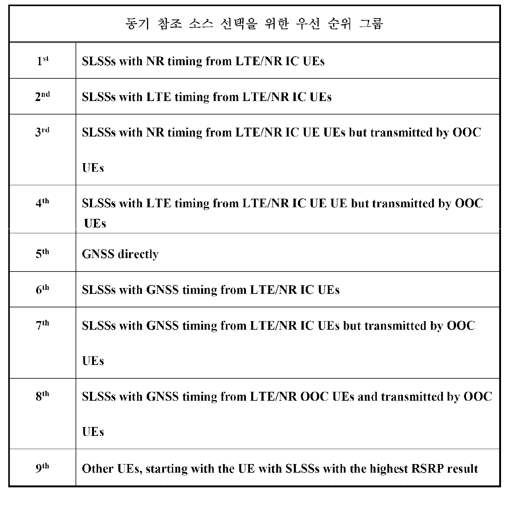
또한, 일 예로, 표 16은 기설정(Preconfiguration) 내에 동기우선권 순서(SyncPriority order)가 “eNB(1st)-> NR(2nd)->GNSS(3rd)”로 설정된 경우일 수 있다. 일 예로, 상술한 경우는 기설정(Preconfiguration) 내에 동기우선권(SyncPriority)이 “eNB”가 설정된 경우와 동일할 수 있다. 따라서, LTE 타이밍에 대한 SLSS를 LTE/NR 인커버리지 단말로부터 획득하는 경우에 대한 그룹이 최우선시될 수 있다. 다음으로, NR 타이밍에 대한 SLSS를 LTE/NR 인커버리지 단말로부터 획득하는 경우에 대한 그룹이 다음으로 우선시될 수 있다. 다음으로, LTE 타이밍에 대한 SLSS를 LTE/NR 인커버리지 단말로부터 획득하는 경우지만 OOC 단말로부터 수신하는 경우에 대한 그룹이 다음으로 우선시될 수 있다. 다음으로, NR 타이밍에 대한 SLSS를 LTE/NR 인커버리지 단말로부터 획득하는 경우지만 OOC 단말로부터 수신하는 경우에 대한 그룹이 다음으로 우선시될 수 있다. 다음으로, GNSS 타이밍에 대한 SLSS를 LTE/NR 인커버리지 단말로부터 획득하는 경우에 대한 그룹이 다음으로 우선시될 수 있다. 다음으로, GNSS 타이밍에 대한 SLSS를 LTE/NR 인커버리지 단말로부터 획득하는 경우지만 OOC 단말로부터 수신하는 경우에 대한 그룹이 다음으로 우선시될 수 있다. 다음으로, GNSS 타이밍에 대한 SLSS를 OOC 단말로부터 수신하는 경우에 대한 그룹이 다음으로 우선시될 수 있다.In addition, as an example, Table 16 may correspond to a case in which a SyncPriority order is set to “eNB (1st)-> NR (2nd)-> GNSS (3rd)” in a preconfiguration. For example, the above-described case may be the same as the case where SyncPriority is set to “eNB” in a preconfiguration. Therefore, the group for the case of obtaining the SLSS for the LTE timing from the LTE / NR coverage terminal may be prioritized. Next, the group for the case of obtaining the SLSS for the NR timing from the LTE / NR coverage terminal may be prioritized next. Next, the group for the case of receiving the SLSS for the LTE timing from the LTE / NR in-coverage terminal but from the OOC terminal may be prioritized next. Next, the group for the case of receiving the SLSS for the NR timing from the LTE / NR in-coverage terminal but from the OOC terminal may be prioritized next. Next, the group for the case of obtaining the SLSS for the GNSS timing from the LTE / NR incovery terminal may be prioritized next. Next, the group for the case of receiving the SLSS for the GNSS timing from the LTE / NR in-coverage terminal but from the OOC terminal may be prioritized next. Next, the group for the case of receiving the SLSS for the GNSS timing from the OOC terminal may be prioritized next.
[표 16]TABLE 16

실시예 2-2-2Example 2-2-2
상술한 바처럼 실시예 2-2-2에서는 기설정(Preconfiguration) 내에 어떤 파라미터가 미리 설정되었는지에 따라서 우선순위를 결정하는 방법을 6가지 경우를 모두 고려한 실시예일 수 있다 (GNSS 타이밍, LTE 타이밍 및 NG 타이밍 각각 비교). 즉, 실시예 2-2-1과 다르게 모든 가능한 조합 6가지 경우에 대해서 그 우선순위 그룹을 나눌 수 있다.As described above, the embodiment 2-2-2 may be an embodiment considering all six cases of the method of determining the priority according to which parameter is preset in the preconfiguration (GNSS timing, LTE timing and NG timings respectively). That is, unlike the embodiment 2-2-1, the priority group can be divided for all six possible combinations.
이때, 일 예로, 표 17은 기설정(Preconfiguration) 내에 동기우선권 순서(SyncPriority order)가 “GNSS(1st) -> eNB(2nd)->NR(3rd)”로 설정된 경우일 수 있다. 따라서, GNSS가 설정되는 경우에는 GNSS로부터 직접 받은 신호를 최우선시 할 수 있다. 다음으로, 네트워크 커버리지 내에서 전송되는 SLSS들 중 LTE 타이밍을 가지는 SLSS가 그 다음 우선 순위를 갖을 수 있다. 다음으로 NR 타이밍을 가지는 SLSS가 그 다음 우선 순위를 가질 수 있다. 다음으로, GNSS 타이밍을 가지는 SLSS가 그 다음 우선 순위를 가질 수 있다. 다음으로는 네트워크 커버리지 밖에서 전송되는 SLSS들 중 LTE 타이밍을 가지는 SLSS가 그 다음 우선 순위를 갖을 수 있다. 다음으로 NR 타이밍을 가지는 SLSS가 그 다음 우선 순위를 가질 수 있다. 다음으로, GNSS 타이밍을 가지는 SLSS가 그 다음 우선 순위를 가질 수 있다. 마지막으로 그렇지 않은 SLSS들이 마지막 우선 순위 그룹에 속하며, 하기 표 17과 같다.In this case, as an example, Table 17 may correspond to a case in which a SyncPriority order is set to “GNSS (1st)-> eNB (2nd)-> NR (3rd)” in a preconfiguration. Therefore, when the GNSS is set, the signal directly received from the GNSS can be given priority. Next, of the SLSSs transmitted within the network coverage, the SLSS having the LTE timing may have the next priority. Next, the SLSS with NR timing may have the next priority. Next, the SLSS with GNSS timing may have the next priority. Next, of the SLSS transmitted out of network coverage, the SLSS having the LTE timing may have the next priority. Next, the SLSS with NR timing may have the next priority. Next, the SLSS with GNSS timing may have the next priority. Finally, the other SLSSs belong to the last priority group, as shown in Table 17 below.
[표 17]TABLE 17

다음으로, 기설정(Preconfiguration) 내에 동기우선권 순서(SyncPriority order)가 “GNSS(1st)->NR(2nd)->eNB(3rd)”로 설정된 경우는 하기 표 18과 같을 수 있다. 이때, 표 18은 표 17과 유사할 수 있으며, LTE 타이밍과 NR 타이밍의 우선 순위만 변경될 수 있으며, 구체적인 구성은 하기 표 18과 같다.Next, when the SyncPriority order is set to “GNSS (1st)-> NR (2nd)-> eNB (3rd)” in Preconfiguration, it may be as shown in Table 18 below. In this case, Table 18 may be similar to Table 17, only the priority of the LTE timing and NR timing can be changed, the specific configuration is shown in Table 18 below.
[표 18]TABLE 18

다음으로, 기설정(Preconfiguration) 내에 동기우선권 순서(SyncPriority order)가 “NR(1st)->eNB(2nd)->GNSS(3rd)”로 설정된 경우는 하기 표 19와 같을 수 있다.Next, when the SyncPriority order is set to “NR (1st)-> eNB (2nd)-> GNSS (3rd)” in Preconfiguration, it may be as shown in Table 19 below.
[표 19]TABLE 19

다음으로, 기설정(Preconfiguration) 내에 동기우선권 순서(SyncPriority order)가 “eNB(1st)->NR(2nd)->GNSS(3rd)”로 설정된 경우는 하기 표 20과 같을 수 있다.Next, when the SyncPriority order is set to “eNB (1st)-> NR (2nd)-> GNSS (3rd)” in Preconfiguration, it may be as shown in Table 20 below.
[표 20]TABLE 20

다음으로, 기설정(Preconfiguration) 내에 동기우선권 순서(SyncPriority order)가 “NR(1st)->GNSS(2nd)->eNB(3rd)”로 설정된 경우는 하기 표 21과 같을 수 있다.Next, when the SyncPriority order is set to “NR (1st)-> GNSS (2nd)-> eNB (3rd)” in the preconfiguration, it may be as shown in Table 21 below.
[표 21]TABLE 21

다음으로, 기설정(Preconfiguration) 내에 동기우선권 순서(SyncPriority order)가 “eNB(1st)->GNSS(2nd)->NR(3rd)”로 설정된 경우는 하기 표 22와 같을 수 있다.Next, when the SyncPriority order is set to “eNB (1st)-> GNSS (2nd)-> NR (3rd)” in the preconfiguration, it may be as shown in Table 22 below.
[표 22]TABLE 22

도 8은 실시예 2-2(2-2-1 및 2-2-2)를 고려한 순서도이다.8 is a flowchart in consideration of Example 2-2 (2-2-1 and 2-2-2).
도 8을 참조하면, V2X 사이드링크 통신을 위한 주파수가 아웃오브커버리지(OOC)인 경우, 단말은 동기 참조 소스를 선택할 수 있다. (S810) 이때, OOC인 경우인바, 단말은 기설정(Preconfiguration) 내의 미리 설정된 파라미터에 기초하여 우선 순위 방법을 결정할 수 있다. (S820) 이때, 일 예로, 우선 순위 방법은 실시예 2-2-1처럼 3가지 경우로만 제한하여 결정될 수 있다. 즉, 상술한 실시예 2-2-1처럼 GNSS 타이밍과 LTE 타이밍/NR 타이밍이 비교되어 상술한 실시예처럼 방법이 제한될 수 있다. 또한, 일 예로, 상술한 실시예 2-2-2처럼 6가지 경우를 모두 고려할 수 있다. 즉, GNSS 타이밍, LTE 타이밍 및 NR 타이밍 각각에 기초하여 가능한 조합을 모두 고려할 수 있다. 그 후, 단말은 기설정(Preconfiguration) 내의 동기우선권 순서(SyncPriority order)에 기초하여 우선 순위를 통해 동기 참조 소스를 선택할 수 있으며, 구체적인 방법은 상술한 바와 같다. (S830) Referring to FIG. 8, when the frequency for V2X sidelink communication is out of coverage (OOC), the terminal may select a synchronization reference source. In this case, in case of OOC, the UE may determine a priority method based on a preset parameter in a preconfiguration. In this case, as an example, the priority method may be determined by limiting to only three cases as in the embodiment 2-2-1. That is, the GNSS timing and the LTE timing / NR timing are compared as in the above-described embodiment 2-2-1, so that the method may be limited as in the above-described embodiment. In addition, as an example, all six cases may be considered as in Example 2-2-2. That is, all possible combinations may be considered based on each of GNSS timing, LTE timing, and NR timing. Thereafter, the terminal may select the synchronization reference source through the priority based on the SyncPriority order in the preconfiguration, and the detailed method is as described above. (S830)
한편, 일 예로, 상술한 실시예 2-2-1 또는 실시예 2-2-2 중 어느 방법에 기초하여 우선 순위가 결정될지 여부도 기설정될 수 있다. 즉, 단말은 상술한 실시예 2-2-1 및 실시예 2-2-2 방법을 지원할 수 있지만, 기설정된 값에 기초하여 상술한 방법 중 어느 하나의 방법에 기초하여 우선 순위를 결정할 수 있으며, 상술할 실시예로 한정되지 않는다.Meanwhile, as an example, whether a priority is determined based on any of the above-described embodiments 2-2-1 or 2-2-2 may be preset. That is, the terminal may support the above-described embodiments 2-2-1 and 2-2-2, but may determine the priority based on any one of the above-described methods based on a preset value. However, it is not limited to the Example mentioned above.
실시예 3(NR V2X 사이드링크 단말의 V2X 사이드링크 통신을 위한 주파수가 LTE/NR에 해당하는 3GPP 네트워크 상의 아웃오브커버리지(OOC)인 경우)Embodiment 3 (when the frequency for V2X sidelink communication of the NR V2X sidelink terminal is out of coverage (OOC) on the 3GPP network corresponding to LTE / NR)
실시예 3은 실시예 2처럼 단말의 V2X 사이드링크 통신을 위한 주파수가 LTE/NR에 해당하는 3GPP 네트워크 상에서 OOC인 경우에 대한 실시예일 수 있다. 이때, 일 예로, 각각의 동기 참조 소스 내의 우선 순위 그룹을 정의할 수 있다. 정의된 3개의 그룹 사이의 우선순위는 기설정(Preconfiguration) 내의 동기우선권 순서(SyncPriority order) 파라미터를 정의해서 지시할 수 있다. 이때, 일 예로, 동기우선권 순서(SyncPriority order) 파라미터는 각각의 그룹에 대한 우선 순위만 결정할 수 있다. 일 예로, 기설정(Preconfiguration) 내에 동기우선권 순서(SyncPriority order)가 “NR(1st)->eNB(2nd)->GNSS(3rd)”로 설정된 경우에 각각의 그룹 간 우선 순위는 표23, 표 24 및 표 25처럼 결정될 수 있다. 또한, 일 예로, 그룹 내 순위는 모두 동일할 수 있으며, 상술한 실시예로 한정되지 않는다.The third embodiment may be an embodiment of a case where the frequency for V2X sidelink communication of the UE is OOC on a 3GPP network corresponding to LTE / NR, as in the second embodiment. In this case, as an example, a priority group in each sync reference source may be defined. The priority between the three defined groups may be indicated by defining a SyncPriority order parameter in a preconfiguration. In this case, as an example, the SyncPriority order parameter may determine only the priority for each group. For example, when the SyncPriority order is set to “NR (1st)-> eNB (2nd)-> GNSS (3rd)” in Preconfiguration, the priority between the groups is shown in Table 23 and Table. 24 and Table 25. In addition, as an example, the rankings within the groups may be all the same, and are not limited to the above-described embodiment.
[표 23]TABLE 23

[표 24]TABLE 24

[표 25]TABLE 25

또한, 일 예로, 기설정(Preconfiguration) 내에 동기우선권 순서(SyncPriority order)가 “NR(1st)->GNSS(2nd)->eNB(3rd)”로 설정된 경우에 각각의 그룹 간 우선 순위는 표26, 표 27 및 표 28처럼 결정될 수 있다. 또한, 일 예로, 그룹 내 순위는 모두 동일할 수 있으며, 상술한 실시예로 한정되지 않는다.In addition, as an example, when the SyncPriority order in the Preconfiguration is set to “NR (1st)-> GNSS (2nd)-> eNB (3rd)”, the priority between the respective groups is shown in Table 26. , Table 27 and Table 28 can be determined as. In addition, as an example, the rankings within the groups may be all the same, and are not limited to the above-described embodiment.
[표 26]TABLE 26

[표 27]TABLE 27

[표 28]TABLE 28

또한, 일 예로, 기설정(Preconfiguration) 내에 동기우선권 순서(SyncPriority order)가 “GNSS(1st)->eNB(2nd)->NR(3rd)”로 설정된 경우에는 상술한 표 26 내지 표 28에 기초하여 하기 표 29처럼 우선 순위가 설정될 수 있다.Also, as an example, when the SyncPriority order is set to “GNSS (1st)-> eNB (2nd)-> NR (3rd)” in Preconfiguration, it is based on the aforementioned Tables 26 to 28. The priority may be set as shown in Table 29 below.
[표 29]TABLE 29

또한, 일 예로, 기설정(Preconfiguration) 내에 동기우선권 순서(SyncPriority order)가 “GNSS(1st)->NR(2nd)->eNB(3rd)”로 설정된 경우에는 상술한 표 26 내지 표 28에 기초하여 하기 표 30처럼 우선 순위가 설정될 수 있다.Also, as an example, when the SyncPriority order is set to “GNSS (1st)-> NR (2nd)-> eNB (3rd)” in Preconfiguration, it is based on the aforementioned Tables 26 to 28. The priority may be set as shown in Table 30 below.
[표 30] TABLE 30

또한, 일 예로, 기설정(Preconfiguration) 내에 동기우선권 순서(SyncPriority order)가 “eNB(1st)->GNSS(2nd)->NR(3rd)”로 설정된 경우에는 상술한 표 26 내지 표 28에 기초하여 하기 표 31처럼 우선 순위가 설정될 수 있다.In addition, as an example, when the SyncPriority order is set to “eNB (1st)-> GNSS (2nd)-> NR (3rd)” in the Preconfiguration, it is based on the aforementioned Tables 26 to 28. The priority may be set as shown in Table 31 below.
[표 31] Table 31

또한, 일 예로, 기설정(Preconfiguration) 내에 동기우선권 순서(SyncPriority order)가 “eNB(1st)->NR(2nd)->GNSS(3rd)”로 설정된 경우에는 상술한 표 26 내지 표 28에 기초하여 하기 표 32처럼 우선 순위가 설정될 수 있다.In addition, as an example, when the SyncPriority order is set to “eNB (1st)-> NR (2nd)-> GNSS (3rd)” in Preconfiguration, it is based on the aforementioned Tables 26 to 28. The priority may be set as shown in Table 32 below.
[표 32] Table 32

즉, 기설정(Preconfiguration) 내에 동기우선권 순서(SyncPriority order)에 기초하여 GNSS 타이밍, LTE 타이밍 및 NR 타이밍 중 우선하는 그룹이 결정되고, 그 그룹 내에서 다시 우선 순위가 결정될 수 있으며, 상술한 실시예로 한정되지 않는다.That is, a priority group among GNSS timing, LTE timing, and NR timing may be determined based on a SyncPriority order in a preconfiguration, and the priority may be determined again within the group. It is not limited to.
실시예 4(추가 우선 순위 결정 방법)Example 4 (Additional Priority Determination Method)
또한, 일 예로, 실시예 2 내지 3에서 동일한 우선순위그룹 내에서 동기참조 소스를 위한 복수의 신호가 존재하는 경우에는 복수의 신호 사이에서 추가적으로 우선 순위가 결정될 수 있다. 특히, LTE 타이밍과 NR 타이밍에 해당하는 SLSSID가 수신된 경우(NG-RAN timing)에 그 둘 사이의 우선순위 결정은 단말이 수행할 수 있다. 이때, 일 예로, 복수의 신호에 대한 비교는 수신된 두 개의 소스로부터 신호들의 “ RSRP 값” 또는 “ RSRP 값 및 SCS값”을 비교하여 단말은 참조소스를 결정할 수 있다. In addition, as an example, in the second to third embodiments, when a plurality of signals for a synchronization reference source exist within the same priority group, priority may be additionally determined among the plurality of signals. In particular, when the SLSSIDs corresponding to the LTE timing and the NR timing are received (NG-RAN timing), prioritization between the two may be performed by the terminal. In this case, as an example, the comparison of the plurality of signals may determine the reference source by comparing the "RSRP value" or "RSRP value and SCS value" of the signals from the two received sources.
보다 상세하게는 “ RSRP 값”을 비교하는 방식은 LTE 타이밍과 NR 타이밍에 해당하는 두 개의 소스로부터 신호의 수신 감도에 해당하는 RSRP 값을 비교해서 기설정된 기준값(최소요구 사항에 대한 일정값) 이상인 신호들 중에서 더 큰 값을 가지는 3GPP 네트워크 타이밍을 사용할 수 있으며, 실시예 1과 유사할 수 있다.More specifically, the “RSRP value” comparison method compares an RSRP value corresponding to a reception sensitivity of a signal from two sources corresponding to LTE timing and NR timing, which is equal to or greater than a predetermined reference value (a constant value for minimum requirements). 3GPP network timing with a larger value among the signals may be used, and may be similar to Embodiment 1. FIG.
또는 “RSRP 값 및 SCS값”을 비교하는 방식은 LTE 타이밍과 NR 타이밍에 해당하는 두 개의 소스로부터 신호의 수신 감도에 해당하는 RSRP 값을 비교해서 기설정된 기준값(최소요구 사항에 대한 일정값) 이상인 신호들 중에서 더 큰 SCS값을 가지는 3GPP 네트워크 타이밍을 사용할 수 있다. 이는, 15kHz SCS에 더해서 30, 60, 120, 240 kHz SCS를 설정 가능한 NR 셀의 타이밍은 오직 15kHz SCS를 기반하는 LTE 셀 타이밍 보다 더 높은 시간 레졸루션(time resolution)을 가질 수 있기 때문이며, 이는 실시예 1과 유사할 수 있다. 즉, NR V2X 사이드링크 송수신을 위한 송수신 타이밍을 보다 세밀하게 조정하여 활용할 수 있어 그 자원 활용과 NR SL 와의 호환 관점에서 장점을 제공할 수 있다.Alternatively, the method of comparing “RSRP value and SCS value” compares an RSRP value corresponding to a reception sensitivity of a signal from two sources corresponding to LTE timing and NR timing, which is equal to or greater than a predetermined reference value (a constant value for minimum requirements). Among the signals, 3GPP network timing with a larger SCS value may be used. This is because the timing of NR cells that can set 30, 60, 120, 240 kHz SCS in addition to 15 kHz SCS may have a higher time resolution than LTE cell timing based on only 15 kHz SCS, which is an embodiment. May be similar to one. That is, the transmission and reception timing for the NR V2X sidelink transmission and reception can be finely adjusted to provide advantages in terms of resource utilization and compatibility with the NR SL.
실시예 5(동기 참조 소스 재선택)Example 5 (Synchronous Reference Source Reselection)
또 다른 일 예로, 상술한 바에 기초하여 적어도 한번 동기참조 소스를 선택한 단말은 동기 참조 소스 재선택을 위한 동작을 수행할 수 있다.As another example, the terminal selecting the synchronization reference source at least once based on the above description may perform an operation for reselecting the synchronization reference source.
보다 상세하게는, OOC 경우에서 상술한 방법을 통해 이미 한번 동기 참조 소스를 선택한 단말이 하나의 동기 참조 단말(SyncRef UE)을 선택한 경우를 고려할 수 있다. 이때, 일 예로, 다른 RSRP 값(후보 SyncRef UE)이 기설정된 기준값(최소요구 사항에 대한 일정값) 이상이고, 다른 RSRP 값(후보 SyncRef UE)이 현재 동기 참조 단말(SyncRef UE)과 동일한 우선순위 그룹에 속하는 경우를 고려할 수 있다. 이때, 다른 RSRP 값(후보 SyncRef UE)이 현재 동기 참조 단말(SyncRef UE)의 RSRP 값보다 기설정된 값(최소요구 사항에 대한 일정값)보다 크다면 현재 동기 참조 단말에 대한 동기 소스를 선택하지 않을 수 있다. 즉, 상술한 조건에 기초하여 동기 참조 단말(SyncRef UE)들 중 가장 높은 우선 순위 그룹에 해당하는 신호가 있다면 그 동기 참조 단말(SyncRef UE)을 선택할 수 있다.In more detail, in the OOC case, the case in which the terminal which has already selected the synchronization reference source once selected the one synchronization reference terminal (SyncRef UE) may be considered. At this time, as an example, another RSRP value (candidate SyncRef UE) is equal to or greater than a predetermined reference value (a constant value for minimum requirement), and another RSRP value (candidate SyncRef UE) has the same priority as the current SyncRef UE. Consider the case of belonging to a group. At this time, if another RSRP value (candidate SyncRef UE) is greater than a preset value (a constant value for minimum requirement) than the RSRP value of the current syncRef UE, the synchronization source for the current sync reference UE will not be selected. Can be. That is, based on the above conditions, if there is a signal corresponding to the highest priority group among the SyncRef UEs, the SyncRef UE may be selected.
또한, 일 예로, 다른 RSRP 값(후보 SyncRef UE)이 기설정된 기준값(최소요구 사항에 대한 일정값) 이상이고, 다른 RSRP 값(후보 SyncRef UE)이 더 높은 우선순위 그룹에 속하는 경우, 현재 동기 참조 단말에 대한 동기 소스를 선택하지 않을 수 있다. 즉, 상술한 조건에 기초하여 동기 참조 단말(SyncRef UE)들 중 가장 높은 우선 순위 그룹에 해당하는 신호가 있다면 그 동기 참조 단말(SyncRef UE)을 선택할 수 있다.Also, as an example, if another RSRP value (candidate SyncRef UE) is greater than or equal to a preset reference value (a constant value for minimum requirement), and the other RSRP value (candidate SyncRef UE) belongs to a higher priority group, refer to current synchronization. The synchronization source for the terminal may not be selected. That is, based on the above conditions, if there is a signal corresponding to the highest priority group among the SyncRef UEs, the SyncRef UE may be selected.
또한, 일 예로, GNSS 신호의 신뢰도가 기설정된 기준값(최소요구 사항에 대한 일정값) 이상이고, GNSS가 현재 동기 참조 단말(SyncRef UE) 보다 높은 우선 순위 그룹에 속하는 경우, 현재 동기 참조 단말에 대한 동기 소스를 선택하지 않을 수 있다. 즉, 상술한 조건에 기초하여 동기 참조 단말(SyncRef UE)들 중 가장 높은 우선 순위 그룹에 해당하는 신호가 있다면 그 동기 참조 단말(SyncRef UE)을 선택할 수 있다.For example, when the reliability of the GNSS signal is equal to or greater than a predetermined reference value (a constant value for the minimum requirement), and the GNSS belongs to a higher priority group than the current sync reference UE (SyncRef UE), You may not select a sync source. That is, based on the above conditions, if there is a signal corresponding to the highest priority group among the SyncRef UEs, the SyncRef UE may be selected.
또한, 일 예로, 현재 동기 참조 단말(SyncRef UE)의 RSRP 값이 기설정된 기준값(최소요구 사항에 대한 일정값) 이하인 경우, 현재 동기 참조 단말에 대한 동기 소스를 선택하지 않을 수 있다. 즉, 상술한 조건에 기초하여 동기 참조 단말(SyncRef UE)들 중 가장 높은 우선 순위 그룹에 해당하는 신호가 있다면 그 동기 참조 단말(SyncRef UE)을 선택할 수 있다.Also, as an example, when the RSRP value of the current SyncRef UE is equal to or less than a predetermined reference value (a constant value for the minimum requirement), the synchronization source for the current sync reference terminal may not be selected. That is, based on the above conditions, if there is a signal corresponding to the highest priority group among the SyncRef UEs, the SyncRef UE may be selected.
또한, 일 예로, 단말이 GNSS를 선택한 경우를 고려할 수 있다.Also, as an example, a case in which the UE selects GNSS may be considered.
이때, 다른 RSRP 값(후보 SyncRef UE)이 기설정된 기준값(최소요구 사항에 대한 일정값) 이상이고, 후보 참조 단말(후보 SyncRef UE)이 GNSS 보다 더 높은 우선순위 그룹에 속한다면 해당 GNSS를 선택하지 않을 수 있다. 또한, 일 예로, GNSS 신호의 신뢰도가 기설정된 기준값(최소요구 사항에 대한 일정값)보다 낮은 경우에도 해당 GNSS를 선택하지 않을 수 있으며, 상술한 실시예로 한정되지 않는다.At this time, if another RSRP value (candidate SyncRef UE) is greater than or equal to a preset reference value (a constant value for minimum requirement) and the candidate reference terminal (candidate SyncRef UE) belongs to a higher priority group than GNSS, the corresponding GNSS is not selected. You may not. For example, even when the reliability of the GNSS signal is lower than a predetermined reference value (a constant value for the minimum requirement), the corresponding GNSS may not be selected and is not limited to the above-described embodiment.
한편, 도 9는 상술한 바에 기초하여 NR V2X 사이드링크 통신이 3GPP 네트워크에서 수행되는 시나리오의 일 예일 수 있다. 이때, 3GPP 네트워크(이하, NG-RAN) 상에서 NR V2X 사이드링크 통신이 이루어질 수 있으며, 추가적으로 GNSS 신호의 존재가 고려될 수 있다. Meanwhile, FIG. 9 may be an example of a scenario in which NR V2X sidelink communication is performed in a 3GPP network based on the above description. In this case, NR V2X sidelink communication may be performed on a 3GPP network (hereinafter, NG-RAN), and additionally, the presence of a GNSS signal may be considered.
보다 상세하게는, 도 9를 참조하면, 각각의 NR V2X 사이드링크 단말들은 NG-eNB(910)를 기준으로 IC 또는 OOC인 경우일 수 있다. 또한, gNB(920)을 기준으로 IC 또는 OOC인 경우일 수 있다. 또한, GNSS(930)를 기준으로 IC 또는 OOC인 경우일 수 있다. 이때, 상술한 바와 같은 상황을 고려하여 NR V2X 사이드링크 단말들은 단말의 위치와 능력에 기초하여 동기 참조의 소스를 선택할 수 있으며, 이에 대해서는 하기에서 후술한다. 또한, 일 예로, 도 9와 같은 시나리오 이외에도 하기 표 33과 같은 시나리오들이 고려될 수 있으며, 상술한 실시예로 한정되지 않는다.More specifically, referring to FIG. 9, each of the NR V2X sidelink terminals may be an IC or OOC based on the NG-eNB 910. In addition, the case may be an IC or OOC based on the gNB 920. In addition, the case may be an IC or OOC based on the GNSS 930. In this case, in consideration of the above-described situation, the NR V2X sidelink terminals may select a source of a synchronization reference based on the location and capability of the terminal, which will be described later. In addition, as an example, in addition to the scenario as shown in FIG. 9, scenarios as shown in Table 33 may be considered and are not limited to the above-described embodiment.
[표 33]Table 33

실시예 (NR SL-SSB 물리 자원 위치 지정 방법)Embodiment (NR SL-SSB Physical Resource Positioning Method)
NR SL-SSB 물리 자원 위치 지정 방법으로서 주파수 도메인 관점에서 NR SL-SSB 자원 위치가 지시될 수 있다. 또한, 일 예로, NR SL-SSB 물리 자원 위치 지정 방법으로서 시간 도메인 관점에서 NR SL-SSB 자원 위치가 지시될 수 있다. 또 다른 일 예로, 상술한 주파수 도메인 및 시간 도메인 관점에서의 지시 정보 외에 추가적인 시그널링을 통해 NR SL-SSB 물리 자원 위치가 지시될 수 있으며, 상술한 실시예로 한정되지 않는다.As the NR SL-SSB physical resource location designation method, the NR SL-SSB resource location may be indicated in terms of frequency domain. In addition, as an example, the NR SL-SSB resource location may be indicated from a time domain perspective as an NR SL-SSB physical resource location designation method. As another example, the NR SL-SSB physical resource location may be indicated through additional signaling in addition to the indication information in the above-described frequency domain and time domain view, and is not limited to the above-described embodiment.
실시예 6(주파수 도메인 관점)Example 6 (Frequency Domain Perspective)
LTE 사이드링크와 다르게 NR 사이드링크는 초광대역으로 운용될 수 있다. 이때, 일 예로, LTE 사이드링크에서는 업링크 캐리어(UL carrier)의 가운데 복수의 PRB(Physical Resource Block))에서 SLSS/PSBCH가 전송될 수 있었다. 다만, 상술한 바처럼, 초광대역인 NR 밴드의 특성에 따라서 하나의 주파수(또는 캐리어)의 특정 주파수 위치에서만 SLSS/PSBCH가 전송되지 않을 수 있다. 즉, 하나의 업링크 캐리어(또는 주파수) 내, 하나 이상의 사이드링크 BWP(Sidelink Bandwidth Part, 이하 SL BWP)들이 NR 사이드링크 통신을 위한 자원 풀의 형태로 구성될 수 있다. 이때, 일 예로, 하나 또는 복수의 SL BWP들에 대응하여 NR SL-SSB가 전송될 수 있다.Unlike LTE sidelinks, NR sidelinks can operate in ultra-wideband. In this case, for example, in the LTE sidelink, the SLSS / PSBCH may be transmitted in a plurality of physical resource blocks (PRBs) among uplink carriers. However, as described above, the SLSS / PSBCH may not be transmitted only at a specific frequency position of one frequency (or carrier) according to the characteristics of the NR band which is an ultra wide band. That is, in one uplink carrier (or frequency), one or more sidelink BWPs (SL BWPs) may be configured in the form of a resource pool for NR sidelink communication. In this case, as an example, the NR SL-SSB may be transmitted corresponding to one or a plurality of SL BWPs.
보다 상세하게는, 하기 도 10은 NR Uu 링크의 셀 접속에 연관된 BWP 설정을 나타낸 도면이다. 도 10을 참조하면, NR 캐리어는 적어도 하나 이상의 셀-정의 SSB(Cell-defining SSB, 이하 C-SSB)가 존재할 수 있다. 일 예로, 도 10에서 SSB 1 및 SSB3은 C-SSB일 수 있다. 이때, 각각의 C-SSB는 RMSI(Remaining System Information) (i.e. SIB1)와 연관될 수 있다. RMSI은 하나의 셀을 구성하는데 있어서 필수적으로 NR 기지국에서 제공해야 하는 신호와 정보를 포함할 수 있다. 또한, C-SSB는 항상 싱크 레스터(Sync raster) 상에 위치할 수 있다. 또한, 일 예로, RRC 연결(RRC CONNECTED) 모드에서는 추가적인 SSB들이 측정(measurement) 목적에 기초하여 설정될 수 있다. 이때, 일 예로, 초기 접속 단말들은 특정 NR 밴드내의 싱크 레스터 검색을 통해서 최적의 C-SSB를 선택 및 수신할 수 있다. 이때, 수신한 C-SSB에 연관된 RMSI를 복호함으로써 이후 랜덤 엑세스 절차를 시작으로 초기 셀 접속을 수행할 수 있다. 일 예로, 단말 1(UE 1, 1010) 및 단말 2(UE 2, 1020)는 SSB 1을 수신하고, SSB 1에 연관된 RMSI를 복호화하여 랜덤 엑세스 절차에 기초하여 초기 셀 접속을 수행할 수 있다. 또한, 일 예로, 단말 3(UE 3, 1030)은 SSB 2를 수신하고, SSB 2 에 연관된 RMSI를 복호화하여 랜덤 엑세스 절차에 기초하여 초기 셀 접속을 수행할 수 있다. 즉, 하나의 캐리어 내에는 서로 같거나 혹은 다른 Cell ID 를 이용하여 gNB 셀 설정이 가능할 수 있다. 또한, BWP를 이용한 주파수 활용이 하나의 캐리어 상에서 가능할 수 있다.More specifically, FIG. 10 below illustrates a BWP configuration associated with cell connection of an NR Uu link. Referring to FIG. 10, an NR carrier may have at least one cell-defining SSB (hereinafter referred to as C-SSB). For example, in FIG. 10, SSB 1 and SSB3 may be C-SSBs. In this case, each C-SSB may be associated with a Remaining System Information (RSI) (i.e.SIB1). The RMSI may include signals and information that must be provided by the NR base station essential to configure one cell. In addition, the C-SSB may always be located on a sync raster. In addition, as an example, in the RRC CONNECTED mode, additional SSBs may be set based on a measurement purpose. In this case, as an example, the initial access terminals may select and receive an optimal C-SSB through a sync raster search within a specific NR band. In this case, by decoding the RMSI associated with the received C-SSB, the initial cell access may be performed starting with a random access procedure. For example, UE 1 (UE 1, 1010) and UE 2 (UE 2, 1020) may receive SSB 1, decode RMSI associated with SSB 1, and perform initial cell access based on a random access procedure. Also, as an example, UE 3 (UE 3, 1030) may receive SSB 2, decode RMSI associated with SSB 2, and perform initial cell access based on a random access procedure. That is, gNB cell configuration may be possible using the same or different Cell ID in one carrier. In addition, frequency utilization using BWP may be possible on one carrier.
또한, 일 예로, NR V2X 사이드링크 통신을 수행하는데 있어서 시스템 정보 (e.g. LTE V2X 경우 SIB21)가 셀로부터 제공될 수 있다. 이때, NR에서는 SL-OSI(Sidelink-Other System Information) 채널을 통해서 시스템 정보가 제공될 수 있다. 다만, 일 예로, 시스템 정보는 SL-OSI 채널로 제한하지 않고 시그널링 방법에 따라서 NR PSBCH 또는 RMSI를 통해서 전달될 수 있다. 하기에서는 설명의 편의를 위해 S-OSI를 기준으로 서술하나, NR PSBCH 또는 RMSI에 대해서도 동일하게 적용될 수 있음은 자명할 수 있다.Also, for example, system information (e.g. SIB21 in case of LTE V2X) may be provided from a cell in performing NR V2X sidelink communication. At this time, in the NR, system information may be provided through a Sidelink-Other System Information (SL-OSI) channel. However, as an example, the system information may be transmitted through the NR PSBCH or the RMSI according to the signaling method without being limited to the SL-OSI channel. In the following description, for the sake of convenience, S-OSI is described as a reference, but it may be obvious that the same may be applied to NR PSBCH or RMSI.
이때, 일 예로, SL-OSI 정보 내에서는 NR V2X 통신을 위한 기본적인 자원 풀 정보 설정, 동기화 정보 전송을 위한 설정에 대한 정보가 제공될 수 있다. 또한, 그 밖에도 NR V2X 통신을 위한 다른 설정 정보들이 제공될 수 있으며, 상술한 실시예로 한정되지 않는다. In this case, for example, information on basic resource pool information setting for NR V2X communication and setting for transmission of synchronization information may be provided in the SL-OSI information. In addition, other configuration information for NR V2X communication may also be provided, and is not limited to the above-described embodiment.
이때, 일 예로, 하기의 동기화 정보 전송에 대한 설정 정보들은 하나의 셀에서 제공되는 SL-OSI를 통해서 아이들/비활성화/연결(IDLE/INACTIVE/CONNECTED) 모드 단말 모두에게 제공될 수 있다. 일 예로, 해당 시스템 정보를 제공받지 못한 단말들은 기설정(Pre-configuration) 정보 내에 상술한 동기화 정보 전송에 관한 설정 정보가 제공될 수 있으며, 상술한 실시예로 한정되지 않는다.In this case, as an example, the following configuration information for transmission of synchronization information may be provided to all of idle / inactive / connected mode terminals through the SL-OSI provided in one cell. For example, the terminal that is not provided with the corresponding system information may be provided with the configuration information related to the above-described synchronization information transmission in the pre-configuration information, it is not limited to the above-described embodiment.
한편, 일 예로, 도 11은 자원 풀과 SLSS/PSBCH 블록 사이의 관계를 나타낸 도면이다. 도 11을 참조하면, 자원 풀(resource pool)에 SLSS/PSBCH 블록이 연관되어 있을 수 있다. 일 예로, 하나의 자원 풀(resource pool) 또는 자원 풀 리스트(resource pool list)는 하나 또는 복수의 SLSSID 값을 제공하는 SLSS/PSBCH 블록과 연관될 수 있다. 일 예로, 하나의 자원 풀이 SLSSID 값을 가지는 하나의 SLSS/PSBCH 블록과 연관되는 경우, 해당 SLSS/PSBCH 블록은 해당 자원 풀 내에 존재할 수 있다. 또 다른 일 예로, 하나의 자원 풀이 SLSSID 값을 가지는 복수의 SLSS/PSBCH 블록과 연관될 수 있다. 이때, 복수의 SLSS/PSBCH 블록들은 해당 자원 풀 내에 존재할 수 있으며, 상술한 실시예로 한정되지 않는다. Meanwhile, FIG. 11 is a diagram illustrating a relationship between a resource pool and a SLSS / PSBCH block. Referring to FIG. 11, a SLSS / PSBCH block may be associated with a resource pool. For example, one resource pool or a resource pool list may be associated with a SLSS / PSBCH block that provides one or more SLSSID values. For example, when one resource pool is associated with one SLSS / PSBCH block having a SLSSID value, the corresponding SLSS / PSBCH block may exist in the corresponding resource pool. As another example, one resource pool may be associated with a plurality of SLSS / PSBCH blocks having a SLSSID value. In this case, the plurality of SLSS / PSBCH blocks may exist in the corresponding resource pool, and is not limited to the above-described embodiment.
이때, 일 예로, 도 12는 각각의 셀마다 제공되는 시스템 정보(e.g. SL-OSI)를 이용하여 NR 사이드 링크 자원 풀 및 SL-SSB 설정 지시 방법을 나타낸 도면이다. 이때, 도 12는 NR FDD(Frequency Division Duplex)에서 SUL(Supplementary Uplink) 대역이 존재하는 경우를 나타낸 도면이다. 이때, SUL은 하나의 서빙셀을 구성할 수 있는 DL 캐리어 또는 DL/UL 캐리어에 추가적으로 설정할 수 있는 여분의 UL 캐리어를 의미할 수 있다.In this case, as an example, FIG. 12 is a diagram illustrating a method for indicating NR side link resource pool and SL-SSB configuration using system information (e.g. SL-OSI) provided for each cell. 12 is a diagram illustrating a case where a supplementary uplink (SUL) band exists in an NR frequency division duplex (FDD). In this case, the SUL may refer to an extra UL carrier that can be additionally set to a DL carrier or a DL / UL carrier that can configure one serving cell.
일 예로, 기지국은 시스템 정보(e.g. RMSI or OSI)를 통해서 해당 셀에서 V2X 동기화 정보 설정과 자원풀 설정을 제공할 수 있다. 이때, 단말은 상술한 시스템 정보를 획득하기 위해 DL 캐리어 상에서 C-SSB를 수신할 수 있다. 단말은 선택된 서빙 셀(serving cell)로부터 상술한 V2X 통신을 위한 설정 정보를 시스템 정보를 통해서 수신할 수 있다. For example, the base station may provide V2X synchronization information setting and resource pool setting in the corresponding cell through system information (e.g. RMSI or OSI). In this case, the terminal may receive the C-SSB on the DL carrier to obtain the above-described system information. The terminal may receive the above-described configuration information for V2X communication from the selected serving cell through system information.
보다 상세하게는, 도 12를 참조하면, 제 1 단말(UE 1, 1210)과 제 2 단말(UE 2, 1220)은 Cell ID=5에 캠핑 온(camping on)하여 OSI 정보를 수신하는 단말들일 수 있다. 반면, 제 3 단말(UE 3, 1230)은 Cell ID=6에 캠핑 온 하여 다른 OSI 정보를 수신한 단말일 수 있다. 즉, 제 1 단말(1210)/제 2단말(1220)과 제 3 단말(1230)은 서로 다른 셀에 캠핑 온 한 것으로 볼 수 있으며, 서로 다른 셀의 경우로 볼 수 있다. 이때, 각각의 셀은 서로 다른 초기 하향링크 BWP(initial DL BWP)내의 “Type0 CORESET” 상의 SI-RNTI로 스크램블링 되어 공통 검색 공간(common search space) 상에서 전송되는 PDCCH를 통해서 스케쥴링된 PDSCH 상에서 SIB1 (i.e. RMSI)를 각 셀 내의 단말들에게 제공할 수 있다.More specifically, referring to FIG. 12, the first terminals UE 1 and 1210 and the second terminals UE 2 and 1220 are terminals that camp on on Cell ID = 5 to receive OSI information. Can be. On the other hand, the third terminals UE 3 and 1230 may be terminals that camp on the Cell ID = 6 and receive other OSI information. That is, the first terminal 1210 / the second terminal 1220 and the third terminal 1230 can be seen as camping on different cells, it can be seen as a case of different cells. In this case, each cell is scrambled to SI-RNTI on “Type0 CORESET” in different initial downlink BWPs (SIWs) and SIB1 (ie RMSI) may be provided to terminals in each cell.
해당 SIB1을 수신한 셀 내의 단말들은 OSI 정보를 수신하기 위한 “OSI CORESET” 정보와 스케쥴링 정보를 획득할 수 있으며 지시된 OSI 스케쥴링 정보를 기반으로 OSI를 수신할 수 있다.UEs in the cell receiving the SIB1 may obtain “OSI CORESET” information and scheduling information for receiving OSI information and may receive OSI based on the indicated OSI scheduling information.
이때, 도 12에서 각각의 셀마다 독립적인 OSI 정보를 획득한 단말들은 NR V2X 통신을 위한 셀 특정 RRC 파라미터들을 제공받을 수 있다. 일 예로, Cell ID=5 에서 OSI는 제 1 SL-SSB(840)의 주파수 상의 위치와 연관된 자원풀 정보를 제공할 수 있다. 또한, 일 예로, Cell ID=6에 해당하는 OSI는 제 2 SL-SSB(850-1, 850-2)의 주파수 상의 위치와 연관된 자원풀 정보를 제공할 수 있다.In this case, in FIG. 12, UEs that acquire independent OSI information for each cell may receive cell specific RRC parameters for NR V2X communication. For example, at Cell ID = 5, the OSI may provide resource pool information associated with a location on a frequency of the first SL-SSB 840. Also, as an example, the OSI corresponding to Cell ID = 6 may provide resource pool information associated with a location on frequencies of the second SL-SSBs 850-1 and 850-2.
즉, 상술한 바처림 NR V2X 사이드링크 통신에서는 SL-SSB 송수신 가능한 위치가 사전에 미리 정해져 있지 않고, 주파수 밴드와 연관된 자원 풀 설정에 따라 유동적으로 변동될 수 있는바, NR SL-SSB의 위치에 대한 정보를 제공할 필요성이 있다. 즉, NR V2X 사이드링크 통신에서는 SL-SSB 송수신 가능한 위치가 V2X 사이드링크 통신 서비스를 제공하는 사업자의 설정에 따라서 다르게 설정될 수 있는바, 해당 위치 정보가 단말들에게 제공될 필요가 있다. 따라서, OSI 정보에는 NR V2X 통신을 위한 파라미터로써 적어도 하나의 NR SL-SSB 주파수 위치와 해당 NR SL-SSB와 연관된 자원 풀 리스트 정보를 제공할 수 있다.That is, in the above mentioned NR V2X sidelink communication, a position capable of transmitting / receiving SL-SSB is not previously determined, and may fluctuate depending on a resource pool setting associated with a frequency band. There is a need to provide information. That is, in NR V2X sidelink communication, a location capable of transmitting / receiving SL-SSB may be differently set according to a setting of an operator providing a V2X sidelink communication service. Therefore, corresponding location information needs to be provided to terminals. Accordingly, the OSI information may provide at least one NR SL-SSB frequency position and resource pool list information associated with the corresponding NR SL-SSB as parameters for NR V2X communication.
또한, 일 예로, NR TDD(Time Division Duplex)를 고려할 수 있다. 이때, 일 예로, NR TDD에서는 DL와 UL가 동일한 BWP 인덱스를 가지면서 동작할 수 있다. 즉, 동일한 BWP 설정이 DL와 UP에 적용될 수 있다. 이때, 도 13은 상술한 바를 고려하여 NR TDD 대역에서의 동작을 나타낸 도면이다. 도 13을 참조하면, 도 12와 유사할 수 있으나, DL와 UL가 동일한 BWP 인덱스를 가지면서 동작하는바, 하나의 리소스 풀에 SL-SSB들이 대응될 수 있으며, 정보를 제공하는 동작은 도 12와 유사할 수 있다.Also, as an example, NR TDD (Time Division Duplex) may be considered. In this case, as an example, in NR TDD, DL and UL may operate while having the same BWP index. That is, the same BWP setting may be applied to the DL and the UP. In this case, FIG. 13 is a diagram illustrating the operation in the NR TDD band in consideration of the above description. Referring to FIG. 13, although similar to FIG. 12, DL and UL operate while having the same BWP index, SL-SSBs may correspond to one resource pool, and the operation of providing information is illustrated in FIG. 12. May be similar to
실시예 6-1(NR 기지국에서 NR V2X 단말에게 NR SL-SSB 물리자원의 위치를 제공하는 경우)Example 6-1 (when NR base station provides location of NR SL-SSB physical resource to NR V2X terminal)
상술한 바에 기초하여 NR 기지국은 NR V2X 단말에게 NR SL-SSB 물리 자원의 위치를 제공할 수 있다. 이때, 일 예로, 기지국에 의해서 제공되는 NR SL-SSB 주파수 정보들은 주로 FDD 또는 SUL에 해당하는 캐리어일 수 있다. 이때, 하기에서는 구체적인 주파수 위치 지시 방법에 대해 서술한다. 일 예로, NR SL-SSB 전송 정보에 관한 동기화 정보 전송 설정에 관한 정보는 UL 캐리어 내에 하나 또는 복수의 NR SL-SSB 전송에 대한 것을 포함할 수 있으며, 상술한 실시예로 한정되지 않는다.Based on the above, the NR base station may provide the location of the NR SL-SSB physical resource to the NR V2X terminal. In this case, as an example, the NR SL-SSB frequency information provided by the base station may mainly be a carrier corresponding to FDD or SUL. At this time, a specific frequency position indicating method will be described below. For example, the information on the synchronization information transmission setting about the NR SL-SSB transmission information may include one or a plurality of NR SL-SSB transmissions in the UL carrier and is not limited to the above-described embodiment.
실시예 6-1-1 (NR 기지국 시그널링 정보 이용)Example 6-1-1 (using NR base station signaling information)
일 예로, NR V2X 단말은 NR 기지국에 초기 접속하는 경우에 있어서 NR V2X 단말은 시스템 정보를 NR 기지국으로부터 수신할 수 있다. 이때, 시스템 정보에는 동기화에 대한 설정 정보가 포함될 수 있다. 하기에서는 NR SL-SSB의 주파수 위치를 지시하기 위한 구체적인 방법에 대해 서술한다.For example, when the NR V2X terminal initially accesses the NR base station, the NR V2X terminal may receive system information from the NR base station. In this case, the system information may include setting information for synchronization. The following describes a specific method for indicating the frequency position of the NR SL-SSB.
실시예 6-1-1-1(“ARFCN-ValueNR” 또는 “GSCN”를 통해 NR SL-SSB 주파수 위치 지시)Example 6-1-1-1 (Indication of NR SL-SSB Frequency Location via “ARFCN-ValueNR” or “GSCN”)
일 예로, NR 기지국은 “ARFCN-ValueNR” 또는 “GSCN”를 통해 NR SL-SSB 주파수 위치를 지시할 수 있다. For example, the NR base station may indicate the NR SL-SSB frequency position through “ARFCN-ValueNR” or “GSCN”.
이때, “ARFCN-ValueNR” 값은 NR에서 정의하는 전체 밴드내의 채널 레스터(channel raster)에 대응하는 값일 수 있다. 따라서, 해당 값을 알면 특정 밴드 내의 특정 채널 레스터(channel raster)의 위치를 지시할 수 있다. 이때, “ARFCN-ValueNR” 값이 지시하는 주파수의 위치를 NR SL-SSB의 중심 PRB의 가장 작은 서브캐리어 인덱스(subcarrier index) (e.g. subcarrier #0 of RB#10 of NR-SL SSB(NR-SL SSB 전체 PRB 수가 20인 경우))로 결정할 수 있다. 또한, 일 예로, 주파수 위치를 NR SL-SSB가 할당되는 가장 낮은 PRB 인덱스(PRB#0 of NR SL SSB)의 가장 낮은 서브캐리어 인덱스(Subcarrier#0 of the PRB#0)로 결정할 수 있다. 또 다른 일 예로, NR SL-SSB가 할당되는 다른 PRB의 다른 서브캐리어 인덱스가 이용될 수 있으며, 상술한 실시예로 한정되지 않는다.In this case, the “ARFCN-ValueNR” value may be a value corresponding to a channel raster in all bands defined by NR. Therefore, knowing the value can indicate the position of a particular channel raster (band raster) in a particular band. At this time, the position of the frequency indicated by the “ARFCN-ValueNR” value is determined by the smallest subcarrier index of the center PRB of the NR SL-SSB (eg subcarrier # 0 of RB # 10 of NR-SL SSB (NR-SL). SSB total PRB number 20)). Also, for example, the frequency position may be determined as the lowest subcarrier index (Subcarrier # 0 of the PRB # 0) of the lowest PRB index (PRB # 0 of NR SL SSB) to which the NR SL-SSB is allocated. As another example, another subcarrier index of another PRB to which the NR SL-SSB is allocated may be used, and is not limited to the above-described embodiment.
또한, NR 기지국은 “GSCN (Global Synchronization Channel Number)” 값을 통해 NR SL-SSB 주파수 위치를 지시할 수 있다. 이때, 단말이 지시 받은 GSCN 값은 특정 밴드의 특정 싱크 레스터(Sync raster) 위치에 일대일 할당되므로 그 값을 통해서 NR SL-SSB 주파수 위치를 지시할 수 있다. “ARFCN” 값과 마찬가지로 지시된 주파수 위치는 NR SL-SSB의 중심 PRB의 가장 작은 서브캐리어 인덱스 (e.g. subcarrier #0 of RB#10 of NR-SL SSB(NR-SL SSB 전체 PRB수가 20인 경우))로 결정할 수 있다. 또한, 일 예로, 주파수 위치를 NR SL-SSB가 할당되는 가장 낮은 PRB 인덱스(PRB#0 of NR SL SSB)의 가장 낮은 서브캐리어 인덱스(Subcarrier#0 of the PRB#0)로 결정할 수 있다. 또 다른 일 예로, NR SL-SSB가 할당되는 다른 PRB의 다른 서브캐리어 인덱스가 이용될 수 있으며, 상술한 실시예로 한정되지 않는다.In addition, the NR base station may indicate the NR SL-SSB frequency position through a "GSCN (Global Synchronization Channel Number)" value. In this case, since the GSCN value instructed by the UE is allocated one-to-one to a specific sync raster position of a specific band, the GSCN value may indicate the NR SL-SSB frequency position through the value. Like the “ARFCN” value, the indicated frequency position is the smallest subcarrier index of the center PRB of the NR SL-SSB (eg subcarrier # 0 of RB # 10 of NR-SL SSB (when the total number of PRBs in the NR-SL SSB is 20). Can be determined. Also, for example, the frequency position may be determined as the lowest subcarrier index (Subcarrier # 0 of the PRB # 0) of the lowest PRB index (PRB # 0 of NR SL SSB) to which the NR SL-SSB is allocated. As another example, another subcarrier index of another PRB to which the NR SL-SSB is allocated may be used, and is not limited to the above-described embodiment.
또한, 일 예로, 상술한 두 가지 시그널링(“ARFCN-ValueNR” 또는 “GSCN”)에 추가적인 NR-SL SSB 서브캐리어 오프셋 (subcarrier offset) 시그널링을 통해 추가적으로 UL PRB 경계에 맞는 주파수 위치를 지시할 수 있다. 이때, 시그널링을 통해 단말에게 “ARFCN” 또는 “GSCN” 값이 지시하는 주파수 위치와 UL PRB 사이의 서브캐리어 오프셋 값을 제공할 수 있다. 단말은 이를 통해 UL PRB 경계에 대한 정보를 확인하고, V2X 사이드링크 송수신을 위한 PRB 정보를 제공할 수 있다.In addition, as an example, an additional NR-SL SSB subcarrier offset signaling may be additionally indicated to the above two signaling (“ARFCN-ValueNR” or “GSCN”) to indicate a frequency position that fits the UL PRB boundary. . In this case, the subcarrier offset value between the UL PRB and the frequency position indicated by the "ARFCN" or "GSCN" value may be provided to the UE through signaling. The terminal may check the information on the UL PRB boundary and may provide PRB information for V2X sidelink transmission and reception.
실시예 6-1-1-2(FrequencyInfoUL 내의 absoluteFrequencyPointA 값이 지시하는 UL 캐리어를 위한 Point A 위치에 상대적인 오프셋 값을 제공하여 NR SL-SSB 주파수 위치 지시)Example 6-1-1-2 (NR SL-SSB frequency position indication by providing an offset value relative to the Point A position for the UL carrier indicated by the absoluteFrequencyPointA value in the FrequencyInfoUL)
또 다른 일 예로, 기지국에 의해서 제공된 UL 캐리어를 위한 “Point A” 위치에 상대적인 오프셋 값을 제공하여 NR SL-SSB의 중심 PRB의 가장 작은 서브캐리어 인덱스 (e.g. subcarrier #0 of RB#10 of NR-SL SSB (NR-SL SSB 전체 PRB수가 20인 경우)를 단말에게 지시할 수 있다. 이때, “Point A”는 제공된 UL 캐리어에서 시작 위치에 대한 정보일 수 있다. 따라서, “Point A”로부터 상대적인 오프셋 값을 제공하면 주파수 위치를 확인할 수 있다. 또한, 일 예로, 주파수 위치를 NR SL-SSB가 할당되는 가장 낮은 PRB 인덱스(PRB#0 of NR SL SSB)의 가장 낮은 서브캐리어 인덱스(Subcarrier#0 of the PRB#0)로 결정할 수 있다. 또 다른 일 예로, NR SL-SSB가 할당되는 다른 PRB의 다른 서브캐리어 인덱스가 이용될 수 있으며, 상술한 실시예로 한정되지 않는다.As another example, the smallest subcarrier index (eg subcarrier # 0 of RB # 10 of NR−) of the center PRB of the NR SL-SSB may be provided by providing an offset value relative to the “Point A” position for the UL carrier provided by the base station. The terminal may indicate the SL SSB (when the total number of PRBs of the NR-SL SSB is 20.) In this case, “Point A” may be information about a start position in a provided UL carrier, and thus, relative to “Point A”. In addition, the frequency position may be determined by providing an offset value, and, for example, the frequency position may be the lowest subcarrier index (Subcarrier # 0) of the lowest PRB index (PRB # 0 of NR SL SSB) to which the NR SL-SSB is allocated. of the PRB # 0. As another example, another subcarrier index of another PRB to which the NR SL-SSB is allocated may be used, and is not limited to the above-described embodiment.
또 다른 일 예로, 상술한 오프셋 값은 주파수 밴드마다 특정 서브캐리어 스페이싱(Subcarrier Spacing) 값을 기준으로 유도되는 PRB의 수를 이용하여 지시할 수 있다.As another example, the aforementioned offset value may be indicated by using the number of PRBs derived based on a specific subcarrier spacing value for each frequency band.
보다 상세하게는, 6GHz 이하인 FR1로써 참조 SCS(Reference SCS)에 기초하여 PRB 수가 결정되고, 이에 기초하여 지시될 수 있다. 일 예로, 참조 SCS가 15 kHz인 경우를 고려할 수 있다. 또한, FR1 주파수 범위 내에 존재하는 NR SL 주파수 밴드에서 지원 가능한 SCS 중에서 가장 작은 값이 참조 SCS일 수 있다. 일 예로, FR1에서 NR 사이드링크 주파수 밴드마다 정의된 SCS들이 30kHz, 60 kHz 또는 (30 kHz 및 60 kHz) SCS 들 중에 어느 하나인 경우에는 가장 작은 값인 30kHz를 참조 SCS로 결정할 수 있다. 이때, 상술한 바처럼 오프셋은 참조 SCS에 기초하여 결정되는 PRB 수를 고려하여 지시될 수 있다.More specifically, the number of PRBs can be determined based on the reference SCS (Reference SCS) as FR1 of 6 GHz or less, and can be indicated based on this. As an example, the case where the reference SCS is 15 kHz may be considered. In addition, the smallest value among the SCSs that can be supported in the NR SL frequency band existing within the FR1 frequency range may be the reference SCS. For example, when the SCSs defined for each NR sidelink frequency band in FR1 are any of 30 kHz, 60 kHz, or (30 kHz and 60 kHz) SCSs, the smallest value 30 kHz may be determined as the reference SCS. In this case, as described above, the offset may be indicated in consideration of the number of PRBs determined based on the reference SCS.
또한, 일 예로, 6GHz 초과 주파수인 FR2에서는 참조 SCS가 60kHz일 수 있다. 이때, PRB는 참조 SCS에 기초하여 결정될 수 있는바, 오프셋은 참조 SCS에 기초하여 결정되는 PRB 수를 고려하여 지시될 수 있으며, 상술한 실시예로 한정되지 않는다.Also, as an example, the reference SCS may be 60 kHz in FR2, which is greater than 6 GHz. In this case, the PRB may be determined based on the reference SCS, and the offset may be indicated in consideration of the number of PRBs determined based on the reference SCS and is not limited to the above-described embodiment.
실시예 6-1-1-3(UL 캐리어의 “Transmission BW”의 시작에 상대적인 오프셋 값을 통해서 NR SL-SSB 주파수 위치 지시)Example 6-1-1-3 (Indication of NR SL-SSB Frequency Position Through Offset Value Relative to Start of “Transmission BW” of UL Carrier)
또 다른 일 예로, NR SL-SSB 주파수 위치는 UL 캐리어의 전송 대역폭(Transmission Bandwidth)의 시작 위치에 대한 상대적인 오프셋 값을 통해서 지시될 수 있다.As another example, the NR SL-SSB frequency position may be indicated through a relative offset value with respect to a start position of a transmission bandwidth of a UL carrier.
도 14는 전송 대역폭의 시작 위치에 기초하여 NR SL-SSB 주파수 위치가 지시되는 방법을 나타낸 도면이다.14 is a diagram illustrating how an NR SL-SSB frequency position is indicated based on a start position of a transmission bandwidth.
보다 상세하게는, 도 14를 참조하면, UL 캐리어에 대한 주파수 정보에는 이용 가능한 주파수 자원의 시작(offsetToCarrier) 정보, 대역폭(carrierBandwith) 정보 및 SCS값에 대한 정보가 제공될 수 있다. 이때, 상술한 정보 중 “Point A” 대비 “offsetToCarrier”만큼 떨어져 있는 UL 주파수 자원부터 실제 데이터 전송에서 이용될 수 있다. 일 예로, “Point A”부터 “offsetToCarrier”만큼 떨어진 주파수 위치까지는 초기 접속을 위한 CRB(Common Resource Block)이 전송될 수 있고, 실제 NR Uu/SL 모두 데이터 전송을 “Point A”부터 “offsetToCarrier”만큼 떨어진 주파수 위치 이후에 대한 위치부터 활용할 수 있다. 따라서, NR SL-SSB 위치를 지시하기 위한 방안으로 상술한 정보를 기반으로 유도하여 지시할 수 있다.In more detail, referring to FIG. 14, frequency information on a UL carrier may be provided with information on start-to-carrier information, bandwidth (carrierBandwith) information, and SCS value of available frequency resources. At this time, from the above-described information can be used in the actual data transmission from the UL frequency resources that are separated by "offsetToCarrier" compared to "Point A". For example, a CRB (Common Resource Block) for initial access may be transmitted from a frequency point “Point A” to “offsetToCarrier”, and the actual NR Uu / SL transmits data from “Point A” to “OffsetToCarrier”. It can be used from the position after the distant frequency position. Therefore, as a scheme for indicating the position of the NR SL-SSB, it may be derived and indicated based on the above-described information.
구체적으로, NR SL-SSB 위치는 UL 캐리어의 전송 대역폭(transmission BW)가 시작되는 시점부터 추가 오프셋(offsetToSLSSB#1과 offsetToSLSSB#2) 값을 통해 해당 NR SL-SSB 주파수 위치를 지시할 수 있다. 즉, 각각의 SL-SSB 블록에 대한 오프셋 값을 UL 캐리어의 전송 대역폭(transmission BW)가 시작되는 시점부터 계산하여 각각의 SL-SSB 블록에 대한 주파수 위치를 지시할 수 있다.In detail, the NR SL-SSB location may indicate the corresponding NR SL-SSB frequency location through additional offset (OffsetToSLSSB # 1 and offsetToSLSSB # 2) values from the time when the transmission bandwidth (BW) of the UL carrier starts. That is, the offset value for each SL-SSB block may be calculated from a time point at which the transmission BW of the UL carrier starts to indicate a frequency position for each SL-SSB block.
또한, 추가 오프셋 “offsetToSLSSB”는 PRB의 수를 가지고 지시될 수 있다. 이때, PRB 수에 도출되는 SCS UL 캐리어의 SCS 또는 NR SL-SSB의 SCS일 수 있으며, 상술한 실시예로 한정되지 않는다.In addition, an additional offset “offsetToSLSSB” may be indicated with the number of PRBs. In this case, the SCS derived from the number of PRBs may be the SCS of the UL carrier or the SCS of the NR SL-SSB, which is not limited to the above-described embodiment.
실시예 6-1-1-4(랜덤 엑세스 수행을 위해 정의한 “Initial UL active BWP”의 시작에 상대적인 오프셋 값을 통해서 NR SL-SSB 주파수 위치 지시)Example 6-1-1-4 (Indicating NR SL-SSB Frequency Position Through Offset Value Relative to Start of “Initial UL Active BWP” Defined for Performing Random Access)
또 다른 일 예로, NR 기지국은 랜덤 엑세스 수행을 위해 정의한 “Initial UL active BWP”의 시작에 상대적인 오프셋 값을 통해서 NR SL-SSB 주파수 위치를 지시할 수 있다. 이때, 일 예로, 단말이 NR SL-SSB 주파수 위치를 확인하는 경우에 있어서 SL-OSI에 포함된 정보를 이용할 수 있다. 이때, RMSI(SIB1)가 SL-OSI보다 먼저 전송될 수 있으며, 단말 입장에서는 RMSI(SIB1)을 통해 NR SL-SSB 주파수 위치를 확인하는 경우에 주파수 위치 정보를 더 빠르게 확인할 수 있다. 상술한 점을 고려하여, NR SL-SSB 주파수 위치를 지시를 위해 RMSI(SIB1)에서 제공하는 “initial UL active BWP”에 대한 정보를 이용할 수 있다. 즉, 초기 UL 활성화 BW를 기반으로 해당 BWP가 시작하는 주파수에서 상대적 오프셋 값을 제공하여 NR SL-SSB 위치를 지시할 수 있으며, 이를 통해 NR SL-SSB의 주파수 위치를 빠르게 단말에게 지시할 수 있다. 또한, 일 예로, 상대적 오프셋 또는 추가 오프셋 “offsetToSLSSB”를 통해 NR SL-SSB의 주파수 위치가 지시될 수 있다. 한편, 일 예로, 상대적 오프셋 또는 추가 오프셋 “offsetToSLSSB”는 PRB의 수에 기초하여 지시될 수 있다. 이때, PRB 수 결정에 기반이 되는 SCS는 UL 캐리어의 SCS 또는 Initial UL active BWP SCS (e.g. Msg.1 SCS or Msg.3 SCS)일 수 있으며, 상술한 실시예로 한정되지 않는다.As another example, the NR base station may indicate the NR SL-SSB frequency position through an offset value relative to the start of “Initial UL active BWP” defined for performing random access. In this case, as an example, when the UE checks the NR SL-SSB frequency position, information included in the SL-OSI may be used. At this time, the RMSI (SIB1) may be transmitted earlier than the SL-OSI, and the terminal position may check the frequency position information faster when checking the NR SL-SSB frequency position through the RMSI (SIB1). In consideration of the foregoing, information on “initial UL active BWP” provided by the RMSI (SIB1) may be used for indicating the NR SL-SSB frequency position. That is, based on the initial UL activation BW can provide a relative offset value at the frequency started by the corresponding BWP to indicate the NR SL-SSB position, through which the terminal can quickly indicate the frequency position of the NR SL-SSB. . In addition, as an example, the frequency position of the NR SL-SSB may be indicated through a relative offset or an additional offset “offsetToSLSSB”. Meanwhile, as an example, the relative offset or the additional offset “offsetToSLSSB” may be indicated based on the number of PRBs. In this case, the SCS based on the determination of the number of PRBs may be SCS of UL carrier or Initial UL active BWP SCS (e.g. Msg. 1 SCS or Msg. 3 SCS), which is not limited to the above-described embodiment.
실시예 6-1-1-5(NR 사이드링크 자원 풀 시작 (subcarrier#0 of PRB#0)에 상대적인 오프셋 값을 통해서 NR SL-SSB 주파수 위치 지시)Example 6-1-1-5 (Indication of NR SL-SSB Frequency Location through Offset Value Relative to NR Sidelink Resource Pool Start (subcarrier # 0 of PRB # 0))
또 다른 일 예로, 기지국은 NR 사이드링크 자원 풀의 시작에서 상대적인 오프셋 값을 통해 NR SL-SSB 주파수 위치를 지시할 수 있다. 도 15는 NR 사이드링크 자원 풀에 기초하여 NR SL-SSB 주파수 위치를 지시하는 방법을 나타낸 도면이다.As another example, the base station may indicate the NR SL-SSB frequency position through a relative offset value at the start of the NR sidelink resource pool. FIG. 15 illustrates a method of indicating an NR SL-SSB frequency position based on an NR sidelink resource pool. FIG.
보다 상세하게는, NR 기지국은 NR SL OSI을 통해 동기화 정보 전송을 위한 설정 정보뿐만 아니라 사이드링크 자원풀에 대한 정보를 단말에게 제공할 수 있다. 이때, NR SL OSI 내 자원풀 리스트 내에 연관된 NR SL-SSB 전송을 위한 동기화 정보 전송에 대한 설정 정보가 제공될 수 있다. 이때, 적어도 하나의 자원풀이 특정 SL-SSB와 연관될 수 있으며, 자원풀과 연관된 동기화 정보 설정 정보를 기지국은 단말에게 제공할 수 있다. 따라서, 각각의 NR 사이드링크 자원풀의 특정 주파수 위치 (e.g. subcarrier#0 of PRB#0 for a NR SL resource pool/pool list)에 추가적인 오프셋 값을 단말에게 제공하여 단말은 해당 자원풀에 연관된 NR SL SSB 주파수 위치를 확인할 수 있다. 일 예로, 도 15를 참조하면, “SL resource pool#1”의 시작 위치를 기준으로 오프셋 값을 지시할 수 있다. 일 예로, “SL resource pool#1”의 시작 위치는 “subcarrier#0 of PRB#0 for a NR SL resource pool 1”에 기초하여 결정될 수 있다. 이때, “SL resource pool#1”와 연관된 SL-SSB로서 SL-SSB#1은 추가 오프셋 값(offsetToSLSSB#1)에 의해 주파수 위치가 지시될 수 있다. 유사하게, “SL resource pool#2”의 시작 위치는 “subcarrier#0 of PRB#0 for a NR SL resource pool 2”에 기초하여 결정될 수 있다. 이때, “SL resource pool#2”와 연관된 SL-SSB로서 SL-SSB#2는 추가 오프셋 값(offsetToSLSSB#2)에 의해 주파수 위치가 지시될 수 있다. 한편, 상술한 실시예들과 유사하게 상대적 오프셋 또는 추가 오프셋 “offsetToSLSSB”는 PRB의 수에 기초하여 지시될 수 있다. 이때, PRB 수 결정에 기반이 되는 SCS는 해당 자원풀에 설정된 SCS를 기준으로 결정될 수 있으며, 상술한 실시예로 한정되지 않는다.In more detail, the NR base station may provide the terminal with information on the sidelink resource pool as well as configuration information for transmitting synchronization information through the NR SL OSI. In this case, configuration information for transmission of synchronization information for NR SL-SSB transmission associated with the resource pool list in the NR SL OSI may be provided. In this case, at least one resource pool may be associated with a specific SL-SSB, and the base station may provide synchronization information configuration information associated with the resource pool to the terminal. Therefore, by providing an additional offset value to the UE in a specific frequency position (eg subcarrier # 0 of PRB # 0 for a NR SL resource pool / pool list) of each NR sidelink resource pool, the UE provides an NR SL associated with the corresponding resource pool. You can check the SSB frequency position. For example, referring to FIG. 15, an offset value may be indicated based on the start position of “SL resource pool # 1”. For example, a start position of “SL resource pool # 1” may be determined based on “subcarrier # 0 of PRB # 0 for a NR SL resource pool 1”. At this time, the SL-SSB # 1 as the SL-SSB associated with the “SL resource pool # 1” may be indicated by the additional offset value offsetOffSLSSB # 1. Similarly, the start position of “SL resource pool # 2” may be determined based on “subcarrier # 0 of PRB # 0 for a NR SL resource pool 2”. In this case, the SL-SSB # 2 as the SL-SSB associated with the “SL resource pool # 2” may be indicated by the additional offset value offsetOffSLSSB # 2. Meanwhile, similarly to the above-described embodiments, the relative offset or the additional offset “offsetToSLSSB” may be indicated based on the number of PRBs. In this case, the SCS based on the PRB number determination may be determined based on the SCS set in the corresponding resource pool, and is not limited to the above-described embodiment.
또한, 일 예로, 상술한 시그널링은 PRB의 수 또는 복수의 PRB 수 (e.g. subchannel) 단위로 지시될 수 있다. 이때, 서브채널은 자원풀 마다 설정된 최소 데이터 스케쥴링 단위로 정의하여 사용될 수 있는 주파수 자원일 수 있다.In addition, as an example, the aforementioned signaling may be indicated in units of a number of PRBs or a plurality of PRBs (e.g. subchannel). In this case, the subchannel may be a frequency resource that can be defined and used in a minimum data scheduling unit set for each resource pool.
실시예 6-1-2(RRC 연결 모드 단말의 경우)Example 6-1-2 (In case of RRC connected mode terminal)
또 다른 일 예로, 단말이 RRC 연결(RRC Connected) 모드인 경우를 고려할 수 있다. 이때, 단말은 RRC 재설정 메시지를 통해 상술한 실시예 6-1-1-1 내지 실시예 6-1-1-5에 대한 정보를 제공 받을 수 있다. 즉, 단말은 상술한 정보들을 RRC 재설정 메시지를 통해 획득할 수 있다. 이때, RRC 연결 모드 단말은 OSI를 통해서 제공받은 NR SL-SSB 주파수 상의 위치 정보에서 RRC 재설정 메시지를 통해 수신한 정보에 기초하여 NR SL-SSB를 추가할 수 있다. 또한, 일 예로, RRC 연결 모드 단말은 OSI를 통해서 제공받은 NR SL-SSB 주파수 상의 위치 정보에서 RRC 재설정 메시지를 통해 수신한 정보에 기초하여 새로운 NR SL-SSB들로 재설정(또는 오버라이트, overwrite)할 수 있다. As another example, the case in which the UE is in an RRC connected mode may be considered. In this case, the UE may be provided with the information on the above-described embodiments 6-1-1-1 to 6-1-1-5 through the RRC reset message. That is, the terminal may obtain the above information through the RRC reset message. In this case, the RRC connected mode terminal may add the NR SL-SSB based on the information received through the RRC reconfiguration message from the location information on the NR SL-SSB frequency provided through the OSI. In addition, as an example, the RRC connected mode UE resets (or overwrites) new NR SL-SSBs based on information received through an RRC reset message from location information on the NR SL-SSB frequency provided through OSI. can do.
일 예로, 단말은 NG-RAN의 시스템 정보를 통해 하나의 NR SL-SSB#1를 수신하여 아이들/비활성화(IDLE/INACTIVE) 모드로 동작할 수 있다. 이후, 단말이 RRC 연결 모드로 전환되어 동작하는 경우, 단말에 NR SL-SSB#2가 추가로 설정되어 이후 동기화 정보 참조 소스 및 타이밍을 검출하는데 신뢰성을 향상시킬 수 있다. 따라서, 해당 설정이 제공된 단말은 복수의 SLSSID 값을 각각 가지는 복수의 SL-SSB를 수신할 수 있다. 이때, 단말은 복수의 SL-SSB들은 동일한 동기화 소스 및 타이밍 값을 제공한다고 가정할 수 있다. 또한, 일 예로, 단말이 QCL(Quasi Co-Located) 관련 시그널링을 추가로 수신하지 않는 경우, 단말은 복수의 SL-SSB들이 서로 Quasi-co located 되었다고 가정할 수 있으며, 상술한 실시예로 한정되지 않는다.For example, the terminal may receive one NR SL-SSB # 1 through the system information of the NG-RAN and operate in an idle / inactive mode. Subsequently, when the terminal is switched to the RRC connected mode to operate, NR SL-SSB # 2 is additionally set in the terminal to improve reliability in detecting the synchronization information reference source and timing. Accordingly, the terminal provided with the corresponding configuration may receive a plurality of SL-SSBs each having a plurality of SLSSID values. In this case, the terminal may assume that the plurality of SL-SSBs provide the same synchronization source and timing value. In addition, as an example, when the UE does not further receive quasi co-located (QCL) related signaling, the UE may assume that a plurality of SL-SSBs are quasi-co located with each other, and are not limited to the above-described embodiment. Do not.
이때, 일 예로, 하나의 단말에 2개 이상의 SL-SSB가 설정되고, 관련된 QCL 설정이 제공된 경우, 단말은 제공된 QCL 설정에 기초하여 QCL 타입을 기반으로 SL-SSB 를 통한 타이밍 값과 RSRP 값을 측정할 수 있다. 이때, QCL 이란 복수의 SL-SSB 내의 SLSS 및/또는 PSBCH DMRS 들끼리 서로 도플러 쉬프트, 도플러 스프레드, 평균 지연, 딜레이 스프레드, spatial Rx parameter 관점에서 서로 quasi co-located 되었다고 단말이 가정한다고 의미할 수 있다.In this case, as an example, when two or more SL-SSBs are configured in one terminal and related QCL configuration is provided, the terminal may determine a timing value and an RSRP value through the SL-SSB based on the QCL type based on the provided QCL configuration. It can be measured. In this case, the QCL may mean that the UE assumes that the SLSS and / or PSBCH DMRSs in the plurality of SL-SSBs are quasi co-located with each other in terms of Doppler shift, Doppler spread, average delay, delay spread, and spatial Rx parameter. .
실시예 6-1-3(OOC 단말의 경우(Pre-configuration의 경우))Example 6-1-3 (In case of OOC terminal (in case of pre-configuration))
또 다른 일 예로, 단말이 NG-RAN 기지국 커버리지 밖에 존재하는 경우를 고려할 수 있다. 즉, 아웃오브커버리지(Out-of Coverage)에 존재하는 단말은 시스템 정보를 사전에 수신하지 못했다면 사전에 미리 설정된 정보를 기반으로 제공받을 수 있다. 일 예로, 사전에 미리 설정된 정보는 상술한 실시예 6-1-1-1 내지 실시예 6-1-1-5에 대한 시그널링 방법이 포함되어 단말에게 제공될 수 있으며, 상술한 실시예로 한정되지 않는다.As another example, the case where the terminal exists outside the NG-RAN base station coverage may be considered. That is, the terminal existing in out-of-coverage may be provided based on the preset information if the terminal does not receive the system information in advance. For example, the preset information may be provided to the terminal including the signaling method for the above-described embodiments 6-1-1-1 to 6-1-1-5, and is limited to the above-described embodiment. It doesn't work.
실시예 6-2(ng-eNB (E-UTRA) 기지국에서 NR V2X 단말에게 NR SL-SSB 물리자원의 위치를 제공하는 경우)Example 6-2 (when ng-eNB (E-UTRA) base station provides the location of NR SL-SSB physical resource to NR V2X terminal)
또 다른 일 예로, 상술한 실시예 6-1에서는 NR 기지국에서 NR V2X 단말에게 NR SL-SSB의 주파수 위치를 지시하는 경우에 대해 서술하였다. 즉, 상술한 실시예는 NR 기지국으로부터 시스템 정보 형태로 단말들에게 NR 사이드링크 동기화 정보 전송을 위한 설정 정보를 제공하는 형태일 수 있다.As another example, in the above-described embodiment 6-1, the case in which the NR base station indicates the frequency position of the NR SL-SSB to the NR V2X terminal has been described. That is, the above-described embodiment may be in the form of providing configuration information for transmitting the NR sidelink synchronization information to the terminals in the form of system information from the NR base station.
이때, 일 예로, 단말이 NG-eNB 기지국 커버리지 내에 위치는 하는 경우를 고려할 수 있다. 이때, 단말은 NG-eNB DL 캐리어 상에서 전송되는 시스템 정보 내에 포함된 NR 사이드 동기화 정보 전송을 위한 설정을 수신해야 NR SL-SSB 전송을 위한 정보를 확인할 수 있다. In this case, as an example, the case where the terminal is located within the NG-eNB base station coverage may be considered. In this case, the terminal may receive the setting for transmitting the NR side synchronization information included in the system information transmitted on the NG-eNB DL carrier to confirm the information for NR SL-SSB transmission.
즉, NR 사이드링크 단말은 LTE 커버리지 내에서 NR 사이드링크 V2X 통신을 위한 동기화 설정 정보를 LTE DL 를 통해서 제공 받을 수 있다. 따라서, NR 사이드링크 단말은 LTE DL 상에서 시스템 정보를 수신할 수 있어야 할 필요성이 있다. 이때, NR 사이드링크 단말은 LTE DL을 통해 수신한 시스템 정보를 통해 NR UL 캐리어 상에서 NR 사이드링크 통신을 수행할 수 있다.That is, the NR sidelink terminal may receive synchronization configuration information for NR sidelink V2X communication within the LTE coverage through the LTE DL. Therefore, the NR sidelink terminal needs to be able to receive system information on the LTE DL. In this case, the NR sidelink terminal may perform NR sidelink communication on the NR UL carrier through system information received through the LTE DL.
이때, 일 예로, 상술한 실시예 6-1-1-1 내지 실시예 6-1-1-5 중에서 실시예 6-1-1-4는 NR에서 초광대역을 사용함을 고려하여 초기 UL 활성화 BWP의 시작 위치에 대한 정보인바, LTE DL을 통해 수신된 시스템 정보에 포함되지 않을 수 있다. 다만, 상술한 실시예 6-1-1-4를 제외한 다른 실시예들은 LTE DL 상의 시스템 정보를 통해서 NR 사이드링크 단말에게 제공될 수 있다. 즉, 실시예 6-1-1-4는 NR DL 캐리어에서 고려될 수 있는 동작이므로 LTE DL 시스템 정보에서는 적용하기 어려울 수 있으며, 다른 시그널링 방법에서는 적용이 가능할 수 있다. At this time, for example, in the above-described embodiments 6-1-1-1 to 6-1-1-5, the embodiment 6-1-1-4 is the initial UL activation BWP in consideration of using the ultra-wideband in NR Information on the start position of the bar may not be included in the system information received through the LTE DL. However, other embodiments except for the above-described embodiment 6-1-1-4 may be provided to the NR sidelink terminal through system information on the LTE DL. That is, since the embodiment 6-1-1-4 may be considered in the NR DL carrier, it may be difficult to apply in the LTE DL system information, and may be applicable in other signaling methods.
실시예 7(시간 도메인 관점)Example 7 (Time Domain Perspective)
상술한 실시예 6에 기초하여 NR SL SSB 주파수 위치가 지시될 수 있다. 이때, 추가적으로 NR SL SSB에 대한 시간 전송 자원 위치도 지시될 필요성이 있다. 일 예로, NR 사이드링크 단말이 3GPP 네트워크 커버리지 (i.e. LTE 및 NR 기지국) 내에서 NR 사이드링크 V2X 통신을 수행하는 경우를 고려할 수 있다. 이때, 시간 도메인 상에서 NR SL SSB 전송 위치가 결정될 필요성이 있으며, 이때 LTE/NR Uu 링크 상에서의 DL/FL/UL 자원 설정이 고려될 필요성이 있다.Based on Embodiment 6 described above, the NR SL SSB frequency position may be indicated. In this case, it is also necessary to indicate the time transmission resource location for the NR SL SSB. As an example, a case in which the NR sidelink terminal performs NR sidelink V2X communication within 3GPP network coverage (i.e. LTE and NR base station) may be considered. At this time, the NR SL SSB transmission position needs to be determined in the time domain, and DL / FL / UL resource configuration on the LTE / NR Uu link needs to be considered.
하기에서는 NR 사이드링크 V2X 통신을 위한 자원풀 구성 방법과 독립적으로 NR SL SSB 전송 시간 자원에 대한 방법에 대해 서술한다. 즉, 상술한 실시예 6처럼 NR SL SSB의 주파수 위치와 연계될 수 있지만, 시간 자원인바 독립적으로 지시될 수 있으며, 상술한 실시예로 한정되지 않는다.In the following, a method for NR SL SSB transmission time resources is described independently of a method for configuring a resource pool for NR sidelink V2X communication. That is, although it may be associated with the frequency position of the NR SL SSB as in the sixth embodiment, the time resource may be independently indicated, and is not limited to the above-described embodiment.
이때, 일 예로, NR 사이드링크 V2X 통신은 고주파 주파수 밴드 영역에서 운용되고 신호 감쇄에 대응하기 위해 복수의 빔 기반으로 수행될 수 있다. 따라서, NR SL SSB 전송 역시 이를 고려해야 할 필요성이 있다. 다만, 일 예로, 단말 구현이나 운용되는 밴드의 특성에 따라서 단일 빔을 기준으로 동작하는 것도 가능할 수 있으며, 상술한 실시예로 한정되지 않는다. In this case, as an example, the NR sidelink V2X communication may be operated in a high frequency frequency band region and may be performed based on a plurality of beams to correspond to signal attenuation. Therefore, NR SL SSB transmission also needs to consider this. However, for example, it may be possible to operate based on a single beam according to the terminal implementation or the characteristics of the band to be operated, and is not limited to the above-described embodiment.
다만, 상술한 환경을 고려하여 LTE 사이드링크와는 다르게 NR V2X를 위한 NR 사이드링크는 동기 신호(PSSS/SSSS) 및 브로드캐스트 채널(e.g. PSBCH)을 하나의 블록 형태로 전송할 필요성이 있으며, 버스트한 구조를 가지고 시간 도메인 상에서 주기적으로 전송할 필요성이 있다. However, in consideration of the above-described environment, unlike the LTE sidelink, the NR sidelink for NR V2X needs to transmit a synchronization signal (PSSS / SSSS) and a broadcast channel (eg PSBCH) in one block form. There is a need to have a structure to transmit periodically in the time domain.
또한, 일 예로, NR FDD/UL와 TDD에서 모두 DL/FL/UL 슬랏 및 심볼들이 가변적으로 설정될 수 있다. 다만, NR 시스템의 시스템 운용을 고려하면 DL SSB 송수신 동작이 보장될 필요성이 있다. 즉, 시스템 정보로서 반드시 제공되는 정보임을 고려하여 DL SSB 송수신에 대한 동작을 보장될 필요성이 있다. 이를 위해서 DL SSB가 전송되는 시간 및 주파수 영역은 항상 DL로 설정될 필요성이 있다. 또한, 단말 역시 상술한 설정에 기초하여 DL SSB 수신 동작을 수행할 수 있다. 즉, NR 기지국은 DL SSB를 전송하는 DL SSB인덱스들을 항상 DL 심볼로 동작하도록 설정할 수 있다. 일 예로, FDD/TDD/SUL에 상관없이 SFI (Slot Format Indicator by DCI format 2_0 with SFI-RNTI) 지시자를 통해서 각 슬랏 마다 DL/FL/UL 심볼들의 비율을 주기적으로 조정할 수 있다. 이때, 일 예로, 셀 내에서 NR 기지국이 전송하는 DL SSB는 항상 DL가 되도록 관련된 시그널링을 DL로 지시할 수 있다. Also, as an example, DL / FL / UL slots and symbols may be variably set in both NR FDD / UL and TDD. However, in consideration of the system operation of the NR system, DL SSB transmission / reception operation needs to be guaranteed. That is, it is necessary to ensure the operation for DL SSB transmission and reception in consideration of the information that is necessarily provided as system information. For this purpose, the time and frequency domain in which the DL SSB is transmitted need to be always set to DL. In addition, the terminal may also perform a DL SSB reception operation based on the above-described configuration. That is, the NR base station may set the DL SSB indexes for transmitting the DL SSB to always operate as DL symbols. For example, regardless of FDD / TDD / SUL, a slot format indicator by DCI format 2_0 with SFI-RNTI (SFI) indicator may periodically adjust the ratio of DL / FL / UL symbols for each slot. In this case, as an example, the DL SSB transmitted by the NR base station in a cell may indicate related signaling to the DL so that the DL is always DL.
또한, 일 예로, TDD UL-DL 설정도 해당 DL SSB 가 전송되는 심볼은 항상 DL 슬롯/심볼(slot/symbol들)이 되도록 할 수 있다. 단말 역시 상술한 바에 기초하여 항상 DL SSB가 전송되는 심볼은 DL로 가정하고 수신 동작을 수행할 수 있다.In addition, as an example, a TDD UL-DL configuration may also allow a symbol on which a corresponding DL SSB is transmitted to always be a DL slot / symbols. The terminal may also assume that the symbol on which the DL SSB is always transmitted is DL based on the above description and perform a reception operation.
이때, 상술한 바를 고려하여 NR SL-SSB이 어느 시점에 전송되는지 여부에 대한 결정이 필요할 수 있다. 즉, DL-SSB 전송이 보장되어야 하는바, SL-SSB는 적어도 DL-SSB가 전송되는 시간을 피해서 전송될 필요성이 있다.In this case, in consideration of the above, it may be necessary to determine at what time the NR SL-SSB is transmitted. That is, since the DL-SSB transmission should be guaranteed, the SL-SSB needs to be transmitted at least avoiding the time when the DL-SSB is transmitted.
일 예로, TDD 인 경우에서는 DL/UL가 동시에 존재할 수 없는바, SL-SSB는 DL-SSB가 전송되는 시간을 피해서 전송될 수 있다. 또한, 일 예로, FDD 인 경우에서도 단말이 하나의 송수신 RF 체인만을 가지는 경우에는 DL 상에서 전송되는 신호(e.g. DL SSB)와 UL 상에서 전송 또는 수신되는 신호(e.g. SL-SSB)에 대한 멀티플렉싱이 제약될 수 있다. For example, in the case of TDD, DL / UL may not exist at the same time, so the SL-SSB may be transmitted by avoiding the time when the DL-SSB is transmitted. Further, for example, even in the case of FDD, when the UE has only one transmit / receive RF chain, multiplexing on a signal transmitted on the DL (eg DL SSB) and a signal transmitted or received on the UL (eg SL-SSB) may be restricted. Can be.
또한, 일 예로, 상술한 FDD와 TDD 모두 동일한 SL-SSB 시간 전송 구조를 가지도록 설정하는 것은 구현을 간단하게 할 수 있으며, 상술한 실시예로 한정되지 않는다. 상술한 바를 고려하여, 하기에서는 DL SSB와 SL SSB는 TDM(Time Division Multiplexing) 방식으로 그 시간 자원의 위치가 결정되는 것으로 고려할 수 있다. 하기에서는 보다 구체적인 SL-SSB 버스트 셋(SL-SSB burst set)에 대해 서술한다.Also, for example, setting the above-described FDD and TDD to have the same SL-SSB time transmission structure may simplify the implementation and is not limited to the above-described embodiment. In consideration of the above, it can be considered that the DL SSB and the SL SSB are determined by the time division multiplexing (TDM) method for determining the location of time resources. Hereinafter, a more specific SL-SSB burst set will be described.
보다 상세하게는, 시간 도메인에서 SL SSB 버스트의 위치를 지시할 수 있다. 일 예로, NR-SL SSB 전송은 시간 도메인 관점에서 하나의 NR-SL SSB 버스트 셋(NR-SL SSB burst set)을 구성할 수 있다. 이때, NR 시스템과 마찬가지로 NR 사이드링크도 높은 주파수 밴드 상에서의 신호 감쇄, 커버리지 유지 및 전송 효율을 제공하기 위해서 빔기반 전송을 고려할 수 있다. 따라서, 하나의 NR-SL SSB 버스트 셋에는 하나 이상의 NR-SL SSB로 구성될 수 있다.More specifically, the position of the SL SSB burst in the time domain can be indicated. For example, NR-SL SSB transmission may configure one NR-SL SSB burst set from a time domain perspective. In this case, like the NR system, the NR sidelink may consider beam-based transmission to provide signal attenuation, coverage maintenance, and transmission efficiency on a high frequency band. Thus, one NR-SL SSB burst set may consist of one or more NR-SL SSBs.
이때, 일 예로, NR-SL SSB 버스트 셋의 주기( )가 설정될 수 있다. 이때,
  는 하나의 값으로 고정하여 사용될 수 있다. 또한, 일 예로, PSL-SSB는 [5, 10, 20, 40, 80, 160, 320, 640ms] 중에 어느 하나로 설정될 수 있다. 또한, 일 예로,
  는 사전에 설정될 수 있으며, 상술한 실시예로 한정되지 않는다.At this time, as an example, the period of the NR-SL SSB burst set ( ) Can be set. At this time, Can be used as a fixed value. Also, as an example, the PSL-SSB may be set to any one of [5, 10, 20, 40, 80, 160, 320, 640 ms]. Also, as an example, May be set in advance and is not limited to the above-described embodiment.
또한, NR-SL SSB 버스트 셋의 시간 윈도우 구간( )이 설정될 수 있다. 이때,
  길이는 복수 개의 값들 중 어느 하나가 선택되어 사용될 수 있다. 또한, 일 예로, NR-SL SSB 버스트 셋의 시작 지점(
 )이 설정될 수 있으며, SSL-SSB 을 지시하는 시그널링이 필요할 수 있다. 즉, NR-SL SSB 버스트 셋에 있어서 주기 정보인
  , 시간 윈도우 정보인
  및 시작 지점에 대한 정보인 SSL-SSB 이 필요할 수 있다.In addition, the time window interval of the NR-SL SSB burst set ( ) Can be set. At this time, As the length, any one of a plurality of values may be selected and used. Also, as an example, the starting point of the NR-SL SSB burst set ( ) May be set and signaling indicating SSL-SSB may be required. That is, the period information in the NR-SL SSB burst set Time window information And SSL-SSB which is information about the starting point.
이때, 일 예로, 하기 표 34는 NR-SL SSB 버스트 셋의 시간 윈도우 길이인  를 설정하는 방법일 수 있다. 또한, 하기 표 35는 NR-SL SSB 버스트 셋의 시작 지점에 대한 정보인
  에 대한 정보일 수 있다.In this case, as an example, Table 34 shows a time window length of an NR-SL SSB burst set. It may be a method of setting. In addition, Table 35 shows information about the starting point of the NR-SL SSB burst set. It may be information about.
보다 상세하게는, NR-SL SSB 버스트 셋의 시간 윈도우 길이는 하프 프레임의 단위인 5ms 단위에 기초하여 지시될 수 있으며, 이는 하기 표 34의 옵션 1과 같다. 이때, 일 예로, 5ms 단위는 K개까지 설정될 수 있으며, 이에 기초한 지시가 수행될 수 있다.More specifically, the time window length of the NR-SL SSB burst set may be indicated based on a 5 ms unit that is a half frame unit, which is the same as option 1 of Table 34 below. In this case, as an example, up to K units may be set up to 5 ms, and an indication based on this may be performed.
또한, 일 예로, NR-SL SSB 버스트 셋의 시간 윈도우 길이는 슬롯 수 단위로 지시될 수 있으며, 이는 하기 표 34의 옵션 2와 같다. 이때, 일 예로, 슬롯은 320개까지 설정될 수 있으며, 이에 기초한 지시가 수행될 수 있다.Also, as an example, the time window length of the NR-SL SSB burst set may be indicated in units of slots, which is the same as option 2 of Table 34 below. In this case, as an example, up to 320 slots may be set, and an indication based on this may be performed.
또한, NR-SL SSB 버스트 셋의 시간 윈도우 길이는 설정된 SSB 수에 기초하여 지시될 수 있으며, 이는 하기 표 34의 옵션 3과 같다. 이때, 일 예로, SSB 수는 L개까지 설정될 수 있으며, 이에 기초한 지시가 수행될 수 있다. In addition, the time window length of the NR-SL SSB burst set may be indicated based on the set number of SSBs, which is the same as option 3 in Table 34 below. In this case, as an example, the number of SSBs may be set up to L, and an indication based on this may be performed.
또한, NR-SL SSB 버스트 셋의 시간 윈도우 길이는 시간 단위로서 “msec”에 의해 지시될 수 있으며, 이는 옵션 4와 같다.In addition, the time window length of the NR-SL SSB burst set may be indicated by “msec” as a time unit, which is the same as option 4.
[표 34]Table 34

또한, 일 예로, NR-SL SSB 버스트 셋의 시작 지점이 하기 표 35에 기초하여 지시될 수 있다. 이때, NR-SL SSB 버스트 셋의 시작 지점은 “NR SL-OffsetIndicatorSyn”파라미터에 기초하여 지시될 수 있으며, 구체적인 지시 방법은 하기 표 35와 같을 수 있다.Also, as an example, the starting point of the NR-SL SSB burst set may be indicated based on Table 35 below. At this time, the start point of the NR-SL SSB burst set may be indicated based on the “NR SL-OffsetIndicatorSyn” parameter, and specific indication methods may be as shown in Table 35 below.
보다 상세하게는, NR-SL SSB 버스트 셋의 시작 지점은 5ms 단위로 지시될 수 있다. 이때, 하나의 프레임에서 각각의 하프 프레임이 5ms인바, 0 또는 1 값을 통해 시작 지점이 지시될 수 있으며, 이는 표 12의 옵션 1과 같다.In more detail, the starting point of the NR-SL SSB burst set may be indicated in units of 5 ms. At this time, since each half frame is 5ms in one frame, a starting point may be indicated through a value of 0 or 1, which is the same as option 1 of Table 12.
또한, NR-SL SSB 버스트 셋의 시작 지점은 슬롯 단위로 지시될 수 있으며, 슬롯 위치를 지시하여 시작 지점을 지시할 수 있으며, 이는 표 35의 옵션 2와 같다.In addition, a start point of the NR-SL SSB burst set may be indicated in units of slots, and may indicate a start point by indicating a slot position, which is the same as option 2 of Table 35.
또한, NR-SL SSB 버스트 셋의 시작 지점은 SSB 인덱스로 지시될 수 있다. 이때, SSB 인덱스 값을 통해 시작 지점이 지시될 수 있으며, 이는 표 35의 옵션 3과 같다. In addition, the starting point of the NR-SL SSB burst set may be indicated by the SSB index. In this case, a starting point may be indicated through the SSB index value, which is the same as option 3 of Table 35.
또한, NR-SL SSB 버스트 셋의 시작 지점은 msec 수 단위로서 그 시작 지점이 지시될 수 있다. 일 예로, 상술한 “TDD UL-DL transmission periodicity”로써, P msec에 기초하여 시작 지점의 위치가 지시될 수 있으며, 이는 표 35의 옵션 4와 같다.In addition, a start point of the NR-SL SSB burst set may be indicated as a unit of msec number. For example, as the above-described "TDD UL-DL transmission periodicity", the location of the starting point may be indicated based on P msec, which is the same as option 4 of Table 35.
[표 35]Table 35

즉, 상술한 바처럼 NR-SL SSB 버스트 셋에 대한 시간 도메인 자원 정보가 지시될 수 있다. 이때, 일 예로, 단말은 지시된 시간 도메인 자원 내에서 실제 이용 가능한 SL SSB들을 판단할 필요성이 있다. 보다 상세하게는, NR-SL SSB 버스트 셋에 대한 시간 도메인 자원 정보가 지시되었더라도 단말이 이용 불가능한 경우가 있을 수 있다.That is, as described above, time domain resource information for the NR-SL SSB burst set may be indicated. In this case, as an example, the UE needs to determine the SL SSBs that are actually available within the indicated time domain resources. More specifically, even if time domain resource information for the NR-SL SSB burst set is indicated, there may be a case where the UE is unavailable.
일 예로, FDD/SUL의 경우에는 지시된 SL-SSB 버스트 윈도우 내에 SL SSB들은 모두 UL 상에 위치할 수 있다. 따라서, 단말은 SL-SSB 버스트 윈도우 내에 모든 SL SSB들을 이용 가능한 SSB로 결정할 수 있다.For example, in case of FDD / SUL, all of the SL SSBs may be located on the UL within the indicated SL-SSB burst window. Accordingly, the UE may determine that all SL SSBs are available SSBs in the SL-SSB burst window.
반면, 다른 일 예로, TDD의 경우, 하나의 밴드위드파트/캐리어(BWP/Carrier)가 DL/FL/UL로써 시간에 기초하여 분리되어 설정될 수 있다. 이때, 단말이 SL-SSB 버스트 윈도우 내에 SL SSB들을 전송하기 위해서는 “UL 슬롯” 또는 “UL 슬롯+심볼”에 해당하는 자원이 필요할 수 있다. 따라서, SL SSB들 중 “UL 슬롯” 또는 “UL 슬롯+심볼”에 위치하는 SL SSB들을 이용 가능한 SL SSB로 결정할 수 있다. On the other hand, in another example, in the case of TDD, one band with part / carrier (BWP / Carrier) may be separately set based on time as DL / FL / UL. In this case, in order for the terminal to transmit the SL SSBs in the SL-SSB burst window, a resource corresponding to “UL slot” or “UL slot + symbol” may be needed. Accordingly, the SL SSBs located in the “UL slot” or the “UL slot + symbol” among the SL SSBs may be determined as available SL SSBs.
또한, 일 예로, SL SSB가 UL 심볼만으로 구성된 UL 슬롯에서만 존재할 수 있는 경우를 고려할 수 있다. 이때, SL SSB 버스트 윈도우 내에서 UL 슬롯만이 SL SSB 전송을 위한 후보(candidate)로 고려될 수 있으며, 이에 기초한 시그널링이 수행될 수 있다. 이에 대해서는 후술한다.In addition, as an example, it may be considered that the SL SSB may exist only in a UL slot configured only with a UL symbol. In this case, only the UL slot in the SL SSB burst window may be considered as a candidate for the SL SSB transmission, and signaling based on this may be performed. This will be described later.
또 다른 일 예로, SFI가 설정된 V2X 단말을 고려할 수 있다. 이때, 일 예로, V2X 구현 및 동작을 고려하여 SFI가 NR V2X 단말에게 설정되지 않을 수 있다. 또 다른 일 예로, NR Uu 링크와의 연관성을 고려하여 V2X 단말에게 SFI가 설정될 수 있다. 일 예로, 단말에 SFI가 설정된 경우, 단말은 UL 슬롯” 또는 “UL 슬롯+심볼”에서만 SL SSB들이 존재하는 것으로 인식할 수 있다.As another example, a V2X terminal configured with SFI may be considered. In this case, as an example, the SFI may not be configured for the NR V2X terminal in consideration of V2X implementation and operation. As another example, the SFI may be configured in the V2X terminal in consideration of the association with the NR Uu link. For example, when the SFI is configured in the terminal, the terminal may recognize that the SL SSBs exist only in the UL slot ”or the“ UL slot + symbol ”.
하기에서는 상술한 바와 같이 지시된 SL-SSB 버스트 윈도우에 대한 시간 도메인 자원 정보와 단말의 이용 가능한 SL SSB 결정 방법에 기초한 구체적인 실시예들을 서술한다.Hereinafter, specific embodiments based on time domain resource information for the SL-SSB burst window indicated as described above and available SL SSB determination methods of the UE will be described.
실시예 7-1(5ms 단위 시작 오프셋과 5ms 단위 SL SSB 버스트 윈도우 구간)Example 7-1 (Starting Offset in 5ms and SL SSB Burst Window Interval in 5ms)
도 16 및 도 17은 NR SL SSB 버스트 셋 구성 및 지시 방법을 나타낸 도면이다. 보다 상세하게는, 일 예로, SL SSB 버스트 셋의 시작 지점에 대한 오프셋은 5ms 단위로 지시될 수 있다. 또한, 일 예로, SL SSB 버스트 윈도우 구간도 5ms 단위로 설정될 수 있다.16 and 17 illustrate a method of configuring and indicating an NR SL SSB burst set. More specifically, as an example, the offset with respect to the start point of the SL SSB burst set may be indicated in units of 5 ms. Also, as an example, the SL SSB burst window period may also be set in 5 ms units.
이때, 수학식 3에 의해 SL SSB 버스트 셋의 전송 위치가 지시될 수 있다. 이때, 수학식 3에 기초하면 SL SSB 버스트 셋의 시작 지점(NR SL-OffsetIndicatorSync)은 SL SSB 버스트 셋의 주기에 대한 mod 함수로서 DFN(Direct frame number) 및 하프 프레임에 의해 지시될 수 있다. 이때, 하프 프레임은 5ms 단위로 상술한 바처럼 0 또는 1로 지시될 수 있다.At this time, the transmission position of the SL SSB burst set may be indicated by Equation 3. In this case, based on Equation 3, the start point of the SL SSB burst set (NR SL-OffsetIndicatorSync) may be indicated by a direct frame number (DFN) and a half frame as a mod function for the period of the SL SSB burst set. In this case, the half frame may be indicated by 0 or 1 as described above in 5 ms units.
[수학식 3] [Equation 3]
보다 상세하게는, 수학식 3에서 DFN은 NR 사이드링크의 시간 도메인 참고를 위한 frame 인덱스일 수 있다. 또한, Hf는 하프 프레임 인덱스로 0값은 DFN의 첫 5ms에 해당할 수 있다. 또한, 1(또는 5) 값은 DFN의 뒤 5ms에 해당할 수 있다. 또한, 일 예로, NR-SL SSB burst set periodicity ( )는 하나의 값으로 고정하여 사용될 수 있다. 또한,
  는 {5, 10, 20, 40, 80, 160, 320, 640msec} 중에서 어느 하나로 설정하거나 미리 설정된 값일 수 있으며, 이는 상술한 바와 같다.More specifically, in
 Equation 3, DFN may be a frame index for time domain reference of the NR sidelink. In addition, Hf is a half frame index and a value of 0 may correspond to the first 5ms of the DFN. Also, a value of 1 (or 5) may correspond to 5 ms after the DFN. Also, as an example, NR-SL SSB burst set periodicity ( ) Can be used as a fixed value. Also, May be set to any one of {5, 10, 20, 40, 80, 160, 320, 640 msec} or a preset value, as described above.
이때, 상술한 파라미터로서 “NR SL-OffsetIndicatorSync”는 NG-RAN 기지국으로부터 전송되는 시스템 정보 또는 RRC 재설정 메시지를 통해 실제 NR-SL SSB 버스트 셋 전송 구간을 단말에게 지시할 수 있다. 즉, 단말은 “NR SL-OffsetIndicatorSync”에 대한 정보를 획득하고, 상술한 수학식 3에 기초하여 시작 지점을 확인할 수 있다. 또한, 지시된 시간 구간은 NR SL-SSB 전송을 위해서 사용될 수 있다.In this case, as the above-mentioned parameter, "NR SL-OffsetIndicatorSync" may indicate the actual NR-SL SSB burst set transmission interval to the terminal through system information or an RRC resetting message transmitted from the NG-RAN base station. That is, the terminal obtains information on the "NR SL-OffsetIndicatorSync", and can confirm the starting point based on Equation 3 described above. In addition, the indicated time interval may be used for NR SL-SSB transmission.
또한, 일 예로,  는 TDD UL-DL 설정이 적용되는 하나의 주기를 나타낼 수 있다. 이때,
  은 {0.5, 0.625, 1, 1.25, 2, 2.5, 5, 10} 중 어느 하나의 값이 설정될 수 있다. 이때, TDD 동작은 상술한 바와 같이 설정된
  값에 기초하여 수행될 수 있다. TDD인바 단말은 UL 자원을 확인하여 시간 도메인의 위치를 확인할 수 있다. 이때, 일 예로, TDD UL-DL 설정 지시자는 DL와 FL 및 UL 슬랏/심볼의 비율이
  주기 내에 어떻게 구성되는지를 지시할 수 있으며, 이에 기초하여 동작할 수 있다.Also, as an example, May indicate one period to which the TDD UL-DL configuration is applied. At this time, May be set to any one of {0.5, 0.625, 1, 1.25, 2, 2.5, 5, 10}. At this time, the TDD operation is set as described above. Can be performed based on a value. The TDD Inva UE may identify the location of the time domain by checking the UL resource. In this case, as an example, the TDD UL-DL configuration indicator may have a ratio of DL, FL, and UL slot / symbol. It can indicate how it is configured within the period, and can operate based on it.
이때, 일 예로, 도 16은 FDD/SUL에서의 NR SL SSB 버스트 셋 구성 및 지시 방법일 수 있다. 또한, 도 17은 TDD에서의 NR SL SSB 버스트 셋 구성 및 지시 방법일 수 있다.In this case, as an example, FIG. 16 may correspond to an NR SL SSB burst set configuration and indication method in FDD / SUL. In addition, FIG. 17 may be an NR SL SSB burst set configuration and indication method in TDD.
일 예로, 도 16을 참조하면, 5ms 시간 단위를 기반으로 “NR SL-OffsetIndicatorSync” 파라미터를 통해서 SL-SSB 버스트 시간 윈도우 시작 시점에 대한 정보가 지시될 수 있으며, 이는 상술한 바와 같다. 즉, 하나의 SL SSB 버스트 셋 주기 내 SL-SSB 버스트 시작 위치는 5ms 단위로 상술한 파라미터를 통해서 지시될 수 있다. 구체적인 일 예로, 수학식 3에서  값이 320ms 인 경우, 해당 주기내에 가능한 5ms 단위의 오프셋 값 (NR SL-OffsetIndicatorSync)은 64개가 존재할 수 있다. 이때, 각각의 오프셋 값은 {0, 5, 10, 15, 20, …315msec}를 나타낼 수 있다. 다만, 상술한 바는 하나의 일 예일 뿐, PSL-SSB 및 오프셋 시간 단위 값이 변경되어 설정될 수 있다.For example, referring to FIG. 16, information on a start time of an SL-SSB burst time window may be indicated through a “NR SL-OffsetIndicatorSync” parameter based on a 5 ms time unit, as described above. That is, the SL-SSB burst start position in one SL SSB burst set period may be indicated through the above-described parameters in units of 5ms. As a specific example, in
 Equation 3 If the value is 320ms, 64 offset values (NR SL-OffsetIndicatorSync) possible in the unit of 5ms may exist. At this time, each offset value is {0, 5, 10, 15, 20,... 315 msec}. However, the above description is just one example, and the PSL-SSB and offset time unit values may be changed and set.
또한, 일 예로, SL-SSB 버스트 윈도우 시간 구간(SL-SSB burst window)은 미리 정해진 값 (e.g. 5msec) 또는 설정된 값(e.g. LTE/NR cell 로부터 설정 또는 Preconfiguration 정보)을 기반으로 설정될 수 있다. 이때, 그 윈도우 시간 구간 내에 미리 정의된 각각의 SL-SSB 시간 위치를 기반으로 단말은 SL-SSB들을 선택하여 전송을 수행할 수 있다. 이때, 도 16에서 미리 정해진 SL-SSB 시간 위치는 “SL-SSB candidate”들에 해당할 수 있다. 이때, 일 예로, “SL-SSB candidate”들은 적어도 2개의 파라미터 (offset, window)를 이용하여 정해진 시간 윈도우 내에 미리 정해진 위치에 존재할 수 있다.In addition, as an example, the SL-SSB burst window time interval (SL-SSB burst window) may be set based on a predetermined value (e.g. 5msec) or a set value (e.g. configuration or preconfiguration information from the LTE / NR cell). At this time, the terminal may select and transmit the SL-SSBs based on the respective SL-SSB time positions defined in the window time interval. In this case, the predetermined SL-SSB time position in FIG. 16 may correspond to “SL-SSB candidates”. In this case, as an example, “SL-SSB candidates” may exist at a predetermined position within a predetermined time window using at least two parameters (offset, window).
또한, 일 예로, 도 17은 TDD 경우를 나타낸 도면이다. 이때, TDD는 FDD/SUL 과는 다르게 DL과 FL (Flexible symbols) 및 UL가 시간 도메인에서 나누어질 수 있다. 이때, 상술한, 상기 Ptdd 파라미터는 TDD UL-DL 설정 정보를 기반으로 “SL-SSB candidate”들이 위치할 수 있는 UL 시간 자원 영역을 확인하는데 이용될 수 있다. 즉, SL-SSB 버스트 윈도우 내에 UL 자원 영역을 확인할 수다. 다만, 일 예로, 기지국의 추가적인 설정이나 시그널링 또는 기설정(preconfiguration)에 따라서 플렉서블(Flexible) 심볼도 SL-SSB 전송을 위해 고려될 수 있다. 즉, 추가 설정에 기초하여 SL-SSB 전송이 수행될 수 있으며, 상술한 실시예로 한정되지 않는다.Also, as an example, FIG. 17 is a diagram illustrating a TDD case. In this case, unlike FDD / SUL, TDD may be divided into DL, FL (Flexible symbols), and UL in the time domain. In this case, the above-described Ptdd parameter may be used to identify an UL time resource region in which “SL-SSB candidates” may be located based on TDD UL-DL configuration information. That is, the UL resource region may be identified within the SL-SSB burst window. However, as an example, a flexible symbol may also be considered for SL-SSB transmission according to additional configuration, signaling, or preconfiguration of the base station. That is, the SL-SSB transmission may be performed based on the additional setting, which is not limited to the above-described embodiment.
실시예 7-2(슬롯(또는 슬롯+OFDM 심볼) 단위 시작 오프셋과 슬롯(또는 슬롯+OFDM 심볼) 단위 SL SSB 버스트 윈도우 구간)Example 7-2 (Starting Offset in Slot (or Slot + OFDM Symbol) and SL SSB Burst Window Interval in Slot (or Slot + OFDM Symbol))
도 18 및 도 19는 슬롯(또는 슬롯+OFDM 심볼) 단위에 기초하여 시작 오프셋 및 SL SSB 버스트 윈도우 구간을 설정하는 방법을 나타낸 도면이다.18 and 19 illustrate a method of setting a start offset and an SL SSB burst window interval based on a slot (or slot + OFDM symbol) unit.
일 예로, 슬롯 단위에 기초하여 시작 오프셋을 지시하는 경우에는 하기 수학식 4와 같이 구성될 수 있다. For example, when the start offset is indicated based on the slot unit, it may be configured as shown in Equation 4 below.
[수학식 4][Equation 4]
이때, 수학식 3과 유사하게 DFN(Direct frame number)은 NR SL의 시간 도메인 참고를 위한 프레임 인덱스일 수 있다. 또한, slot number는 DFN 내에 존재 가능한 슬롯의 인덱스로써 0~320 사이의 값을 가질 수 있다. 또한,  는 1ms 시간에 해당하는 서브프레임 내에 존재하는 슬롯의 수를 의미할 수 있다. 또한, 일 예로, “NR-SL SSB burst set periodicity (PSL-SSB)는 하나의 값으로 고정하여 사용될 수 있다. 또한, 일 예로, PSL-SSB 은 {5, 10, 20, 40, 80, 160, 320, 640msec} 중에서 어느 하나로 설정되거나 미리 설정될 수 있으며, 이는 상술한 바와 같다.In this case, similar to Equation 3, the direct frame number (DFN) may be a frame index for the time domain reference of the NR SL. In addition, the slot number may be a value between 0 and 320 as an index of a slot that may exist in the DFN. Also, May mean the number of slots present in a subframe corresponding to a 1 ms time. In addition, as an example, “NR-SL SSB burst set periodicity (PSL-SSB) may be fixedly used as one value. In addition, as an example, the PSL-SSB may be set to any one of {5, 10, 20, 40, 80, 160, 320, 640 msec} or may be set in advance, as described above.
또한, “NR SL-OffsetIndicatorSync”는 NG-RAN 기지국으로부터 전송되는 시스템 정보 또는 RRC 재설정 메시지를 통해 실제 NR-SL SSB 버스트 셋 시작 지점을 단말에게 지시할 수 있다. 이때, 단말은 지시된 시간 구간을 NR SL-SSB 전송을 위해 사용할 수 있으며, 실시예 7-1과 유사할 수 있다. In addition, the “NR SL-OffsetIndicatorSync” may indicate the actual NR-SL SSB burst set start point to the terminal through system information or an RRC reset message transmitted from the NG-RAN base station. In this case, the UE may use the indicated time interval for NR SL-SSB transmission and may be similar to the embodiment 7-1.
다만, “NR SL-OffsetIndicatorSync” 오프셋 값과 SL-SSB 버스트 윈도우 크기를 슬롯 단위로 기지국이 설정하거나 기설정(preconfiguration) 하는 점이 다를 수 있다. 즉, 5ms 단위로 설정하지 않고, 슬롯 단위로 설정할 수 있다. However, the base station may set or preconfigure the offset value of the “NR SL-OffsetIndicatorSync” and the SL-SSB burst window in units of slots. That is, it can be set in slot units instead of in 5 ms units.
이때, 일 예로, 추가적으로 오프셋 값을 Slot 인덱스 + OFDM 심볼 인덱스를 지시할 수 있다. 일 예로, 도 19처럼 SFI가 설정된 V2X 단말과 도 18처럼 TDD 네트워크에서 동작하는 V2X 단말에 있어서 상술한 오프셋 값이 효율적일 수 있다.In this case, as an example, an offset value may additionally indicate a slot index + an OFDM symbol index. For example, the above-described offset value may be effective for the V2X terminal in which the SFI is set as shown in FIG. 19 and the V2X terminal operating in the TDD network as shown in FIG. 18.
보다 상세하게는, TDD 설정이나 SFI 설정은 슬롯 내에 DL/FL/UL의 조합을 제공하는 지시 정보일 수 있다. 이때, slot/msec 단위로는 UL OFDM 심볼들을 정확하게 지시할 수 없다. 또한, 일 예로, URLLC 서비스 중 하나인 V2X 서비스의 요구사항을 만족시키기 위해서는 심볼 레벨 데이터 송수신 동작을 NR V2X에서도 고려할 필요가 있다. 따라서, 상술한 바에서는 보다 정확한 지시를 수행하기 위해 “슬롯” 또는 “슬롯+OFDM 심볼”의 조합으로 지시될 수 있으며, 상술한 실시예로 한정되지 않는다. 또한, 일 예로, SL-SSB 버스트 윈도우 크기가 “슬롯” 또는 “슬롯+OFDM 심볼”의 조합으로 지시될 수 있으며, 상술한 실시예로 한정되지 않는다.More specifically, the TDD setting or the SFI setting may be indication information for providing a combination of DL / FL / UL in a slot. In this case, the UL OFDM symbols cannot be accurately indicated in the slot / msec unit. In addition, for example, in order to satisfy the requirements of the V2X service, which is one of the URLLC services, it is necessary to consider the symbol level data transmission / reception operation in the NR V2X. Therefore, in the above description, in order to perform a more accurate indication, it may be indicated by a combination of "slot" or "slot + OFDM symbol", and is not limited to the above-described embodiment. In addition, as an example, the SL-SSB burst window size may be indicated by a combination of “slot” or “slot + OFDM symbol”, and is not limited to the above-described embodiment.
실시예 7-3(SL-SSB 단위 시작 오프셋과 SL-SSB 단위 SL SSB 버스트 윈도우 구간)Example 7-3 (SL-SSB Unit Start Offset and SL-SSB Unit SL SSB Burst Window Interval)
또 다른 일 예로, SL-SSB 단위 시작 오프셋과 SL-SSB 단위 SL SSB 버스트 윈도우 구간은 SL-SSB 인덱스와 그 수를 통해 단말에게 지시할 수 있다. 보다 상세하게는, 각각의 SL-SSB에는 인덱스가 존재할 수 있고, 실시예 7-1 및 실시예 7-2와 유사하게 DFN으로서 프레임 인덱스 및 SL-SSB에 대한 인덱스를 이용하여 SL-SSB 버스트의 시작 지점을 지시할 수 있다. 또한, 사용되는 SL-SSB 인덱스를 이용하여 SSB 버스트 윈도우 크기도 지시할 수 있으며, 상술한 바로 한정되지 않는다.As another example, the SL-SSB unit start offset and the SL-SSB unit SL SSB burst window interval may be indicated to the UE through the SL-SSB index and the number thereof. More specifically, each SL-SSB may have an index, and similarly to the embodiments 7-1 and 7-2, the SL-SSB burst may be divided by using the frame index as the DFN and the index to the SL-SSB. You can indicate the starting point. In addition, the size of the SSB burst window may be indicated using the SL-SSB index used, and the present invention is not limited thereto.
실시예 8(3GPP 네트워크 또는 기설정(pre-configuration)에서 제공되는 추가적인 SL-SSB 자원 지시 방법)Embodiment 8 (additional SL-SSB resource indication method provided in 3GPP network or pre-configuration)
상술한 실시예 6 및 실시예 7에 기초하여 SL-SSB 버스트 셋에 대한 주파수 위치 및 시간 위치가 지시될 수 있다.Based on the sixth and seventh embodiments described above, the frequency position and the time position for the SL-SSB burst set may be indicated.
이때, 일 예로, 3GPP 네트워크 또는 기설정에서 제공되는 정보에 기초하여 SL-SSB 자원이 추가적으로 지시될 수 있다. In this case, as an example, the SL-SSB resource may be additionally indicated based on information provided in the 3GPP network or the preset.
보다 상세하게는, 상술한 바에서는 SL-SSB 버스트 윈도우 내의 SL-SSB 자원 지시 방법을 통해서 V2X 단말들은 동기 및 MIB 정보를 전달하는 채널 전송을 해당 자원 상에서 수행할 수 있다. 다만, 해당 NR-SL SSB 버스트 셋 시간 구간 내 모든 NR SL-SSB들이 실제 전송을 위해서 사용되지 못할 수 있다. 일 예로, NR 기지국에서 SL-SSB들의 전송을 허여하지 않을 수 있다. 보다 상세하게는, NR 시스템에서 NR 기지국만 DL SSB를 전송할 수 있었다. 다만, NR 사이드링크를 고려하여 SL-SSB 전송이 가능한 단말이 하나 또는 복수 개가 하나의 셀에 존재할 수 있다. 즉, 기존의 NR 시스템과는 다르게 NR 사이드링크는 SL-SSB 전송 가능한 단말이 하나의 셀 내의 다수가 존재하기 때문에 각 단말의 RF 능력, 안테나 설정 및 개수, 빔포밍 전송 방법 중 적어도 어느 하나에 기초하여 실제 사용할 SL-SSB의 수를 단말마다 다르게 설정할 수 있다. 따라서, NR 기지국에 의해 SL-SSB들의 전송이 허여되는지 여부에 대한 추가 시그널링이 필요할 수 있다.In more detail, in the above-described manner, V2X terminals may perform channel transmission for transmitting synchronization and MIB information on corresponding resources through the SL-SSB resource indication method in the SL-SSB burst window. However, all NR SL-SSBs in the corresponding NR-SL SSB burst set time interval may not be used for actual transmission. For example, the NR base station may not allow the transmission of the SL-SSBs. More specifically, in the NR system, only the NR base station could transmit the DL SSB. However, one or more terminals capable of transmitting SL-SSB may be present in one cell in consideration of the NR sidelink. That is, unlike conventional NR systems, since NR sidelinks have multiple terminals capable of transmitting SL-SSB in one cell, the NR sidelink is based on at least one of RF capability, antenna configuration and number, and beamforming transmission method of each terminal. The number of SL-SSBs to be actually used can be set differently for each UE. Thus, additional signaling as to whether the transmission of SL-SSBs is allowed by the NR base station may be necessary.
이때, NR 기지국만 DL SSB를 전송할 수 있지만, NR 기지국 또한 NR Uu 링크 상의 데이터 송수신을 위해 셀 내의 단말들에게 UL 데이터 전송을 위한 자원을 스케쥴링할 수 있다. 이를 위해, NR 기지국은 UL 채널 (e.g. configured PUSCH) 및 시그널들을(e.g. SRS) 설정해야 할 수 있다. 따라서, SL-SSB 전송을 위해서 NR Uu 링크의 상향링크 전송 자원에 대한 사용이 제한될 수 있다. 따라서, 3GPP 네트워크인 LTE/NR 기지국은 NR 사이드링크 단말들에게 NR-SL SSB 버스트 셋 시간 내에서 사용 가능한 SL-SSB 전송 인덱스를 추가적으로 시그널링할 필요성이 있다. 이를 통해, NR UL 캐리어 자원 활용의 효율성을 높일 수 있다.In this case, only the NR base station may transmit the DL SSB, but the NR base station may also schedule resources for UL data transmission to terminals in the cell for transmitting and receiving data on the NR Uu link. To this end, the NR base station may need to configure a UL channel (e.g. configured PUSCH) and signals (e.g. SRS). Therefore, the use of uplink transmission resources of the NR Uu link may be limited for SL-SSB transmission. Accordingly, the LTE / NR base station, which is a 3GPP network, needs to additionally signal the NR sidelink terminals to the SL-SSB transmission index available within the NR-SL SSB burst set time. Through this, it is possible to increase the efficiency of NR UL carrier resource utilization.
하기에서는 보다 구체적인 경우로써, TDD와 FDD/SUL의 경우에 기지국의 추가 SL-SSB 자원 지시 방법에 대해 서술한다.Hereinafter, as a more specific case, an additional SL-SSB resource indication method of the base station in the case of TDD and FDD / SUL will be described.
이때, 하기 실시예에서는 상술한 실시예 6 및 실시예 7에 기초하여 단말이 SL-SSB 버스트 윈도우 시작과 그 크기에 대한 설정 정보를 확인하고, 추가적으로 실제 네트워크에서 “configured SL SSB candidate” 정보로서 실제 이용 가능한 SL-SSB에 대한 정보를 수신한 경우를 고려할 수 있다. 이때, 단말은 지시된 “configured SL SSB candidate”들 중에서 단말 스스로 결정한 “SL SSB candidate” 에서 최종 SL-SSB 전송을 수행할 수 있다. At this time, in the following embodiment, the terminal checks the configuration information on the start and size of the SL-SSB burst window on the basis of the above-described embodiments 6 and 7, and in addition to the actual "configured SL SSB candidate" information in the actual network Consider the case of receiving information on the available SL-SSB. In this case, the terminal may perform the final SL-SSB transmission in the “SL SSB candidate” determined by the terminal itself from among the indicated “configured SL SSB candidates”.
또한, 일 예로, 추가 시그널링이 단말에게 제공되지 않은 경우, 단말은 실시예 6 및 실시예 7에서 수행되는 SL-SSB 버스트 윈도우 시작과 그 크기에 대한 설정 정보만을 기반으로 이용 가능한 “SL SSB candidate”들을 결정할 수 있으며, 상술한 실시예로 한정되지 않는다.In addition, as an example, when additional signaling is not provided to the UE, the UE may use the “SL SSB candidate” available based only on configuration information about the start of the SL-SSB burst window and the size of the SL-SSB bursts performed in Embodiments 6 and 7. And the present invention is not limited to the above-described embodiment.
이때, 일 예로, 도 20은 TDD인 경우를 고려하여 상술한 바에 기초한 추가 시그널링에 대한 동작일 수 있다. 또한, 도 21은 SFI가 있는 FDD/SUL인 경우를 고려하여 상술한 바에 기초한 추가 시그널링에 대한 동작일 수 있다.In this case, as an example, FIG. 20 may be an operation for additional signaling based on the above description in consideration of the case of TDD. In addition, FIG. 21 may be an operation for additional signaling based on the above in consideration of the case of FDD / SUL having SFI.
일 예로, 도 20 및 도 21에서 “L” 값은 NR SL-SSB 버스트 셋 내의 SL-SSB의 수일 수 있다. 이때, 일 예로, NR 사이드링크가 운용되는 주파수 밴드의 범위에 따라서 L 값은 다르게 정해질 수 있으며, 이는 하기 표 36과 같을 수 있다. 일 예로, L 값은 주파수가 높아질수록 커질 수 있다. 즉, 고주파로서 광대역을 이용하는 경우에서 SL-SSB 수가 증가할 수 있다.For example, in FIG. 20 and FIG. 21, the value “L” may be the number of SL-SSBs in the NR SL-SSB burst set. In this case, as an example, the L value may be determined differently according to the range of the frequency band in which the NR sidelink is operated, which may be as shown in Table 36 below. For example, the L value may increase as the frequency increases. That is, the number of SL-SSBs may increase in the case of using a broadband as a high frequency.
[표 36]TABLE 36

또한, 일 예로, 도 20 및 도 21에서 “N” 값은 L 개중 NR-SL SSB 전송을 위해서 네트워크에서 허락하는 자원 인덱스와 수일 수 있다. 이때, 기지국은 N값에 대한 정보를 NR 사이드링크 단말들에게 지시할 수 있다. 일 예로, 지시 방법은 비트맵 또는 인덱스 값일 수 있으나, 상술한 실시예로 한정되지 않는다.In addition, as an example, in FIG. 20 and FIG. 21, the value “N” may be the number and the resource indexes allowed in the network for L-valued NR-SL SSB transmission. At this time, the base station may indicate the information on the N value to the NR sidelink terminals. As an example, the indication method may be a bitmap or an index value, but is not limited to the above-described embodiment.
이때, 일 예로, 단말이 상술한 “N”값에 대한 정보를 수신하지 못한 경우, 단말은 미리 결정된 값에 기초하여 실제 사용하는 SL-SSB를 결정할 수 있다. 또한, 일 예로, 단말은 상술한 L값에 기초하여 NR SL SSB인덱스를 기준으로 실제 사용하는 SL-SSB를 결정할 수 있다.In this case, as an example, when the terminal does not receive the above-described information on the "N" value, the terminal may determine the SL-SSB actually used based on a predetermined value. Also, as an example, the UE may determine the SL-SSB actually used based on the NR SL SSB index based on the L value described above.
또한, 일 예로, 도 20 및 도 21에서 “K”값은 해당 단말에서 실제 사용하는 NR-SL 인덱스 수일 수 있다.In addition, as an example, in FIG. 20 and FIG. 21, the value “K” may be the number of NR-SL indexes actually used by the corresponding terminal.
보다 상세하게는, 도 20 및 도 21을 참조하면, 단말은 상술한 실시예 6 및 실시예 7에 기초하여 SL SSB 버스트 셋에 대한 주파수 위치 및 시간 위치에 대한 지시를 수신할 수 있으며, 이에 기초하여 SL SSB 후보(SL SSB Candidates)가 결정될 수 있다. 그 후, 상술한 바처럼 네트워크에서 허락된 자원 인덱스 및 자원 수(“N”값)에 대한 정보를 추가로 시그널링 받을 수 있다. 이때, 상술한 정보를 수신한 NR 사이드링크 단말들은 지시된 하나 이상의 NR-SL SSB 인덱스들 중에서 각의각 단말마다 빔전송 특성 및 안테나/RF 설정과 전송 방법을 고려하여 실제 전송을 결정할 NR-SL SSB 인덱스와 수(“K”값)와 빔형태를 결정할 수 있다. 그 후, 각각의 단말들은 각각의 NR-SL SSB 전송을 수행할 수 있다. 이때, 일 예로, 단말마다 잠재적으로 다른 “K” 값을 가지고 다른 SL-SSB 인덱스를 기반으로 SL-SSB 전송을 수행할 수 있으며, 상술한 실시예로 한정되지 않는다.In more detail, referring to FIGS. 20 and 21, the terminal may receive an indication of a frequency position and a time position for the SL SSB burst set based on the above-described embodiments 6 and 7, and based on this, SL SSB Candidates may be determined. Thereafter, as described above, information about the resource index and the number of resources (“N” value) allowed in the network may be further signaled. In this case, the NR sidelink terminals receiving the above-described information may determine the actual transmission in consideration of beam transmission characteristics, antenna / RF setting, and transmission method for each terminal among one or more indicated NR-SL SSB indexes. You can determine the SSB index, number (“K” value), and beam shape. Thereafter, each terminal may perform respective NR-SL SSB transmission. In this case, as an example, SL-SSB transmission may be performed based on different SL-SSB indexes with potentially different “K” values for each terminal, and is not limited to the above-described embodiment.
보다 상세하게는, NR 사이드링크 단말은 주파수 밴드에 따라서 전송 가능한 L개의 SSB 중에서 실제 네트워크에서 지시된 NR-SL SSB의 수(“N”값)와 인덱스에 해당하는 슬랏 내의 심볼들의 집합을 결정할 수 있다. 그 후, 단말은 지시된 NR SL-SSB 인덱스들에 해당하는 슬랏 내의 심볼 상에서는 하향링크로 설정 및 사용되지 않도록 할 수 있다. 네트워크(기지국)는 해당 심볼들이 항상 UL이 되도록 보장할 수 있다. 즉, 네트워크와 NR 사이드링크 단말 모두 해당 슬랏 내의 심볼들은 항상 UL 라는 것을 서로 보장할 수 있다. 따라서, NR 사이드링크 단말 관점에서는 항상 원하는 NR SL-SSB를 선택하여 전송을 수행할 수 있다. More specifically, the NR sidelink terminal can determine the number of NR-SL SSBs (“N” values) indicated in the actual network among the L SSBs that can be transmitted according to the frequency band and a set of symbols in the slot corresponding to the index. have. Thereafter, the terminal may be configured and not used as a downlink on a symbol in a slot corresponding to the indicated NR SL-SSB indexes. The network (base station) can ensure that the symbols are always UL. That is, both the network and the NR sidelink terminal can guarantee each other that the symbols in the corresponding slots are always UL. Therefore, from the viewpoint of the NR sidelink terminal, transmission can be performed by selecting a desired NR SL-SSB at all times.
또한, 일 예로, 상술한 바에 기초하여 NR SL-SSB 전송 심볼들이 NR Uu 링크 상의 DL 전송(e.g. PDSCH, CSI-RS 등등)과 충돌하지 않고 안정적으로 송수신이 가능할 수 있다. 이때, 일 예로, 네트워크 관점에서도 상술한 바에 기초하여 슬랏 포맷 지시자 (SFI-RNTI로 스크램블된 common PDCCH를 통해서 지시되는 slot 내의 DL/FL/UL 심볼 구조 지시자)를 통해 UL 심볼들에 대응되도록 지시할 수 있다. 또한, 일 예로, TDD 경우, “TDD UL-DL configurationCommon”, “TDD UL-DL configurationCommon2” 및 “TDD UL-DL configurationDedicated”중 적어도 어느 하나를 NR Uu 단말들에게 제공하여 UL 심볼들에 대응되도록 지시할 수 있다.In addition, as an example, based on the above, NR SL-SSB transmission symbols may be stably transmitted and received without colliding with DL transmission (e.g. PDSCH, CSI-RS, etc.) on the NR Uu link. In this case, as an example, the network view may indicate that the slot format indicator (DL / FL / UL symbol structure indicator in the slot indicated through the common PDCCH scrambled with SFI-RNTI) corresponds to UL symbols based on the above description. Can be. Also, for example, in the case of TDD, at least one of “TDD UL-DL configurationCommon”, “TDD UL-DL configurationCommon2”, and “TDD UL-DL configurationDedicated” is provided to NR Uu terminals to indicate that they correspond to UL symbols. can do.
또한, 상술한 바에서는 TDD 경우 및 SFI가 있는 FDD/SUL에 대해서 서술하였지만, SFI 가 없는 경우에는 모든 슬롯 들이 오직 UL 심볼만으로 구성되는 것으로 가정하여 상술한 시그널링을 적용할 수 있다. 또한, 일 예로, TDD인 경우라도 SFI 값이 적용될 수 있으며, 상술한 실시예로 한정되지 않는다.In addition, although the above has described TDD and FDD / SUL with SFI, in the absence of SFI, the above-described signaling may be applied on the assumption that all slots consist of only UL symbols. In addition, as an example, even in the case of TDD, the SFI value may be applied and is not limited to the above-described embodiment.
또 다른 일 예로, 도 22는 “UL 슬롯” 또는 “UL 슬롯+심볼”에서 이용 가능한 SL-SSB가 위치할 수 있는 경우를 나타낸 도면이다. 일 예로, 상술한 도 20 및 도 21에서는 DL/FL/UL 슬롯 또는 심볼과 무관하게 고정된 위치에 잠재적으로 SL-SSB가 존재하는 경우에 기초하여 시그널링 방법을 서술하였다. 다만, 도 22처럼 UL 슬롯” 또는 “UL 슬롯+심볼”에서만 이용 가능한 SL-SSB가 위치할 수 있는가 상술한 “N”값 및 “K”값의 크기가 줄 수 있다. 이때, 일 예로서, 단말이 실시예 6 및 실시예 7 에 기초하여 SL-SSB 주파수 위치 및 시간 위치를 결정하고, 추가 시그널링을 수신하는 동작은 도 22에서도 동일하게 적용될 수 있으며, 상술한 실시예로 한정되지 않는다.As another example, FIG. 22 illustrates a case where an SL-SSB available in an "UL slot" or an "UL slot + symbol" may be located. As an example, in FIG. 20 and FIG. 21 described above, a signaling method is described based on a case where a SL-SSB is potentially present in a fixed position irrespective of a DL / FL / UL slot or a symbol. However, as shown in FIG. 22, whether the SL-SSB available only in the UL slot ”or the“ UL slot + symbol ”may be located may have the size of the above-described“ N ”value and“ K ”value. In this case, as an example, the operation of determining, by the terminal, the SL-SSB frequency position and the time position based on the sixth and seventh embodiments and receiving additional signaling may be equally applied to FIG. 22. It is not limited to.
또한, 일 예로 도 23은 플로팅 사이드링크 SSB 버스트 (Floating SL SSB burst) 구조를 나타낸 도면이다.In addition, FIG. 23 illustrates a floating side link SSB burst structure as an example.
도 23을 참조하면, SL SSB 버스트 전송은 5ms 경계를 기반으로 수행되지 않을 수 있다. 이때, 일 예로, DFN 내의 슬랏의 수만큼의 오프셋 값의 범위를 이용하여 특정 DFN 내의 특정 슬롯을 시작 지점으로 할 수 있다. 이때, 상술한 SL-SSB의 수인 “L”값 또는 네트워크가 허락하는 값인 “N” 값 중에서 송신 NR V2X 단말이 결정한 “K”값의 SLSS/PSBCH 블록을 사용하여 전송을 수행할 수 있으며, 구체적인 방법은 상술한 바와 같다.Referring to FIG. 23, the SL SSB burst transmission may not be performed based on a 5 ms boundary. In this case, as an example, a specific slot in a specific DFN may be used as a starting point by using a range of offset values corresponding to the number of slots in the DFN. At this time, the transmission may be performed using the SLSS / PSBCH block of the “K” value determined by the transmitting NR V2X UE from among the aforementioned “L” value of the number of SL-SSBs or “N” value allowed by the network. The method is as described above.
한편, 플로팅 SL SSB 버스트의 시작 지점은 기지국이 “NR SL-offsetIndicatorSync” 파라미터를 통해서 DFN 0 대비 “DFN+slot” 인덱스 값을 단말에게 제공하여 지시할 수 있다. 이때, 추가로 “NR SL-lengthIndicatorSync” 파라미터를 통해서 SL SSB 버스트의 크기(또는 길이) 정보를 단말에게 제공할 수 있다. 일 예로, 크기는 슬롯 단위, 서브프레임 단위 또는 “ms” 단위로 지시될 수 있다. 이때, 지시된 윈도우 내에는 가능한 SL-SSB들의 후보 위치가 “L”값으로 정의될 수 있으며, 이는 상술한 바와 같다.On the other hand, the start point of the floating SL SSB burst may be indicated by the base station by providing the terminal with a "DFN + slot" index value compared to DFN 0 through the "NR SL-offsetIndicatorSync" parameter. In this case, additionally, the size (or length) information of the SL SSB burst may be provided to the terminal through the “NR SL-lengthIndicatorSync” parameter. As an example, the size may be indicated in units of slots, subframes, or “ms”. In this case, candidate positions of possible SL-SSBs may be defined as “L” values in the indicated window, as described above.
또한, 일 예로, 상술한 5ms 윈도우 경우와 유사하게 3GPP 네트워크는 “L”값 중에 LTE 또는 NR Uu 링크 상에서 SL-SSB 전송이 가능한 설정들을 고려해서 네트워크에서 설정한 “N”값의 SL-SSB를 시스템 정보를 통해서 각각의 셀마다 설정할 수 있다. 그 후, 단말은 단말의 안테나 설정 및 RF 능력과 빔을 형성하는 방법 및 커버리지 등을 고려하여 “K”값으로서 실제 전송할 SL-SSB 수를 결정하여 전송할 수 있다.For example, similarly to the 5ms window case described above, the 3GPP network selects the SL-SSB of the “N” value set in the network in consideration of the settings for SL-SSB transmission on the LTE or NR Uu link among the “L” values. System information can be set for each cell. Thereafter, the terminal may determine and transmit the actual number of SL-SSBs to be transmitted as a “K” value in consideration of the antenna configuration of the terminal, the RF capability, the method of forming the beam, and the coverage.
실시예 9(DL SSB 버스트 윈도우와 SL SSB 버스트 윈도우가 오버랩되는 경우)Example 9 (when DL SSB burst window overlaps with SL SSB burst window)
또한, 일 예로, 도 24는 DL SSB 버스트 윈도우와 SL SSB 버스트 윈도우가 오버랩되는 경우를 나타낸 도면이다. 이때, 일 예로, DL SSB 버스트 셋과 동일한 5ms 상에서 SL SSB 버스트 전송이 상술한 “NR SL-OffsetIndicatorSync” 값에 의해서 지시된 경우, 도 24의 (a) 내지 (c)와 같이 SL SSB 버스트가 TDM 형태로 단말에게 지시될 수 있다. 일 예로, NR 기지국이 실제 전송하는 DL SSB 버스트와 SL SSB 버스트는 도 24(a)와 같은 형태일 수 있다. 또는, NR 기지국이 실제 전송하는 DL SSB 버스트와 SL SSB 버스트는 도 24(b)와 같은 형태일 수 있다. NR 기지국이 실제 전송하는 DL SSB 버스트와 SL SSB 버스트는 도 24(c)와 같은 형태일 수 있다. 이때, 상술한 바에서 DL SSB 버스트에 대한 중요도가 높을 수 있는바, 항상 우선적으로 전송되고, SL SSB 버스트가 그 이후에 할당될 수 있다. 또한, 일 예로, 네트워크에서 지시한 SL-SSB 전송 인덱스에 해당하는 시간 자원 위치에서 단말은 항상 UL 전송을 수행할 수 있다. 따라서, 단말은 “DCI 포맷 2_0(DCI format 2_0)이 지시하는 SFI 인덱스 값에 해당하는 SL-SSB 전송 심볼들에서는 DL 및/또는 FL 심볼이 설정되지 않을 수 있으며, 상술한 실시예로 한정되지 않는다.In addition, FIG. 24 is a diagram illustrating a case where the DL SSB burst window and the SL SSB burst window overlap. At this time, as an example, when the SL SSB burst transmission is indicated by the above-described "NR SL-OffsetIndicatorSync" value on 5 ms equal to the DL SSB burst set, the SL SSB burst is a TDM as shown in FIGS. 24A to 24C. It may be instructed to the terminal in the form. For example, the DL SSB burst and the SL SSB burst actually transmitted by the NR base station may be as shown in FIG. 24 (a). Alternatively, the DL SSB burst and the SL SSB burst actually transmitted by the NR base station may be as shown in FIG. 24 (b). The DL SSB burst and the SL SSB burst actually transmitted by the NR base station may be as shown in FIG. 24 (c). In this case, as described above, the importance of the DL SSB burst may be high, and therefore, it is always transmitted first, and the SL SSB burst may be allocated thereafter. In addition, as an example, the UE may always perform UL transmission at a time resource location corresponding to the SL-SSB transmission index indicated by the network. Accordingly, the UE may not set DL and / or FL symbols in the SL-SSB transmission symbols corresponding to the SFI index value indicated by the DCI format 2_0, but is not limited to the above-described embodiment. .
도 25는 SL-SSB 자원 설정 방법을 나타낸 도면이다.25 is a diagram illustrating a method for establishing a SL-SSB resource.
도 25를 참조하면, 단말은 SL-SSB 전송을 위한 자원 설정 정보를 기지국으로부터 수신할 수 있다.(S2510) 이때, 도 1 내지 도 24에서 상술한 바와 같이, 단말은 SL-SSB 전송을 위한 자원 설정 정보를 기지국으로부터 수신할 수 있다. 이때, SL-SSB 전송을 위한 자원은 주파수 도메인 관점에서 주파수 위치 정보로서 단말에게 제공될 수 있다. 즉, 상술한 실시예 6처럼 단말은 SL-SSB에 대한 주파수 위치 정보를 기지국으로부터 지시 받을 수 있다. 또한, 일 예로, SL-SSB 전송을 위한 자원은 시간 도메인 관점에서 시간 위치 정보로서 단말에게 제공될 수 있다. 즉, 상술한 실시예 7처럼 단말은 SL-SSB에 대한 시간 위치 정보를 기지국으로부터 지시 받을 수 있다. 또한, 일 예로, 단말은 기지국으로부터 상술한 정보뿐만 아니라 추가 정보를 수신할 수 있다. 즉, 상술한 실시예 8처럼 단말은 SL-SSB와 관련하여 추가 정보를 지시 받을 수 있다.Referring to FIG. 25, the terminal may receive resource configuration information for SL-SSB transmission from the base station (S2510). At this time, as described above with reference to FIGS. 1 to 24, the terminal may transmit resources for SL-SSB transmission. The configuration information can be received from the base station. In this case, the resource for the SL-SSB transmission may be provided to the terminal as frequency position information from the perspective of the frequency domain. That is, as in the sixth embodiment, the terminal may be instructed by the base station to obtain the frequency location information on the SL-SSB. In addition, as an example, resources for SL-SSB transmission may be provided to the terminal as time location information from a time domain perspective. That is, as in the above-described seventh embodiment, the terminal may receive time location information on the SL-SSB from the base station. In addition, as an example, the terminal may receive additional information as well as the above-described information from the base station. That is, as in the above-described eighth embodiment, the terminal may receive additional information regarding the SL-SSB.
이때, 일 예로, 상술한 실시예 6 내지 실시예 8에 대한 정보는 서로 연관되어 수신되는 정보일 수 있다. 또 다른 일 예로, 상술한 실시예 6 내지 실시예 8 각각에 대한 정보는 서로 독립적으로 수신되는 정보일 수 있으며, 상술한 실시예로 한정되지 않는다.In this case, as an example, the information about the sixth to eighth embodiments may be information received in association with each other. As another example, the information on each of the above-described sixth to eighth embodiments may be information independently received from each other, and is not limited to the above-described embodiment.
도 26은 본 개시에 따른 기지국 장치 및 단말 장치의 구성을 나타내는 도면이다.26 is a diagram illustrating the configuration of a base station apparatus and a terminal apparatus according to the present disclosure.
기지국 장치(2600)는 프로세서(2610), 안테나부(2620), 트랜시버(2630), 메모리(2640)를 포함할 수 있다. The base station apparatus 2600 may include a processor 2610, an antenna unit 2620, a transceiver 2630, and a memory 2640.
프로세서(2610)는 베이스밴드 관련 신호 처리를 수행하며, 상위계층 처리부(2611) 및 물리계층 처리부(2612)를 포함할 수 있다. 상위계층 처리부(2611)는 MAC(Medium Access Control) 계층, RRC(Radio Resource Control) 계층, 또는 그 이상의 상위계층의 동작을 처리할 수 있다. 물리계층 처리부(2612)는 물리(physical, PHY) 계층의 동작(예를 들어, 상향링크 수신 신호 처리, 하향링크 송신 신호 처리)을 처리할 수 있다. 프로세서(2610)는 베이스밴드 관련 신호 처리를 수행하는 것 외에도, 기지국 장치(2600) 전반의 동작을 제어할 수도 있다.The processor 2610 performs baseband related signal processing and may include an upper layer processor 2611 and a physical layer processor 2612. The upper layer processor 2611 may process operations of a medium access control (MAC) layer, a radio resource control (RRC) layer, or more upper layers. The physical layer processor 2612 may process operations (eg, uplink reception signal processing and downlink transmission signal processing) of a physical (PHY) layer. In addition to performing baseband related signal processing, the processor 2610 may control the overall operation of the base station apparatus 2600.
안테나부(2620)는 하나 이상의 물리적 안테나를 포함할 수 있고, 복수개의 안테나를 포함하는 경우 MIMO(Multiple Input Multiple Output) 송수신을 지원할 수 있다. 트랜시버(2630)는 무선 주파수(RF) 송신기와 RF 수신기를 포함할 수 있다. 메모리(2640)는 프로세서(2610)의 연산 처리된 정보, 기지국 장치(2600)의 동작에 관련된 소프트웨어, 운영체제, 애플리케이션 등을 저장할 수 있으며, 버퍼 등의 구성요소를 포함할 수도 있다.The antenna unit 2620 may include one or more physical antennas, and may include multiple input multiple output (MIMO) transmission and reception when a plurality of antennas are included. The transceiver 2630 may include a radio frequency (RF) transmitter and an RF receiver. The memory 2640 may store computationally processed information of the processor 2610, software, an operating system, an application, and the like related to the operation of the base station apparatus 2600, and may include components such as a buffer.
기지국(2600)의 프로세서(2610)는 본 발명에서 설명하는 실시예들에서의 기지국의 동작을 구현하도록 설정될 수 있다. Processor 2610 of base station 2600 may be configured to implement the operation of the base station in the embodiments described herein.
단말 장치(2650)는 프로세서(2660), 안테나부(2670), 트랜시버(2680), 메모리(26260)를 포함할 수 있다. The terminal device 2650 may include a processor 2660, an antenna unit 2670, a transceiver 2680, and a memory 26260.
프로세서(2660)는 베이스밴드 관련 신호 처리를 수행하며, 상위계층 처리부(2661) 및 물리계층 처리부(2662)를 포함할 수 있다. 상위계층 처리부(2661)는 MAC 계층, RRC 계층, 또는 그 이상의 상위계층의 동작을 처리할 수 있다. 물리계층 처리부(2662)는 PHY 계층의 동작(예를 들어, 하향링크 수신 신호 처리, 상향링크 송신 신호 처리)을 처리할 수 있다. 프로세서(2660)는 베이스밴드 관련 신호 처리를 수행하는 것 외에도, 단말 장치(2650) 전반의 동작을 제어할 수도 있다.The processor 2660 performs baseband related signal processing and may include an upper layer processor 2661 and a physical layer processor 2662. The upper layer processor 2661 may process operations of the MAC layer, the RRC layer, or more upper layers. The physical layer processor 2662 may process an operation of the PHY layer (for example, downlink reception signal processing and uplink transmission signal processing). In addition to performing baseband related signal processing, the processor 2660 may control the overall operation of the terminal device 2650.
안테나부(2670)는 하나 이상의 물리적 안테나를 포함할 수 있고, 복수개의 안테나를 포함하는 경우 MIMO 송수신을 지원할 수 있다. 트랜시버(2680)는 RF 송신기와 RF 수신기를 포함할 수 있다. 메모리(2690)는 프로세서(2660)의 연산 처리된 정보, 단말 장치(2650)의 동작에 관련된 소프트웨어, 운영체제, 애플리케이션 등을 저장할 수 있으며, 버퍼 등의 구성요소를 포함할 수도 있다.The antenna unit 2670 may include one or more physical antennas, and may support MIMO transmission / reception if the antenna unit 2670 includes a plurality of antennas. The transceiver 2680 may include an RF transmitter and an RF receiver. The memory 2690 may store arithmetic processed information of the processor 2660, software related to the operation of the terminal device 2650, an operating system, an application, and the like, and may include components such as a buffer.
단말 장치(2650)의 프로세서(2660)는 본 발명에서 설명하는 실시예들에서의 단말의 동작을 구현하도록 설정될 수 있다. The processor 2660 of the terminal device 2650 may be configured to implement the operation of the terminal in the embodiments described in the present invention.
기지국 장치(2600) 및 단말 장치(2650)의 동작에 있어서 본 발명의 예시들에서 설명한 사항이 동일하게 적용될 수 있으며, 중복되는 설명은 생략한다.In the operations of the base station apparatus 2600 and the terminal apparatus 2650, the details described in the examples of the present disclosure may be applied in the same manner, and redundant descriptions thereof will be omitted.
본 개시의 예시적인 방법들은 설명의 명확성을 위해서 동작의 시리즈로 표현되어 있지만, 이는 단계가 수행되는 순서를 제한하기 위한 것은 아니며, 필요한 경우에는 각각의 단계가 동시에 또는 상이한 순서로 수행될 수도 있다. 본 개시에 따른 방법을 구현하기 위해서, 예시하는 단계에 추가적으로 다른 단계를 포함하거나, 일부의 단계를 제외하고 나머지 단계를 포함하거나, 또는 일부의 단계를 제외하고 추가적인 다른 단계를 포함할 수도 있다. Exemplary methods of the present disclosure are represented as a series of operations for clarity of description, but are not intended to limit the order in which the steps are performed, and each step may be performed simultaneously or in a different order as necessary. In order to implement the method according to the present disclosure, the illustrated step may further include other steps, may include remaining steps except for some steps, or may include additional other steps except for some steps.
본 개시의 다양한 실시예는 모든 가능한 조합을 나열한 것이 아니고 본 개시의 대표적인 양상을 설명하기 위한 것이며, 다양한 실시예에서 설명하는 사항들은 독립적으로 적용되거나 또는 둘 이상의 조합으로 적용될 수도 있다. The various embodiments of the present disclosure are not an exhaustive list of all possible combinations and are intended to illustrate representative aspects of the present disclosure, and the matters described in the various embodiments may be applied independently or in combination of two or more.
또한, 본 개시의 다양한 실시예는 하드웨어, 펌웨어(firmware), 소프트웨어, 또는 그들의 결합 등에 의해 구현될 수 있다. 하드웨어에 의한 구현의 경우, 하나 또는 그 이상의 ASICs(Application Specific Integrated Circuits), DSPs(Digital Signal Processors), DSPDs(Digital Signal Processing Devices), PLDs(Programmable Logic Devices), FPGAs(Field Programmable Gate Arrays), 범용 프로세서(general processor), 컨트롤러, 마이크로 컨트롤러, 마이크로 프로세서 등에 의해 구현될 수 있다. In addition, various embodiments of the present disclosure may be implemented by hardware, firmware, software, a combination thereof, or the like. For hardware implementations, one or more Application Specific Integrated Circuits (ASICs), Digital Signal Processors (DSPs), Digital Signal Processing Devices (DSPDs), Programmable Logic Devices (PLDs), Field Programmable Gate Arrays (FPGAs), General Purpose It may be implemented by a general processor, a controller, a microcontroller, a microprocessor, and the like.
본 개시의 범위는 다양한 실시예의 방법에 따른 동작이 장치 또는 컴퓨터 상에서 실행되도록 하는 소프트웨어 또는 머신-실행가능한 명령들(예를 들어, 운영체제, 애플리케이션, 펌웨어(firmware), 프로그램 등), 및 이러한 소프트웨어 또는 명령 등이 저장되어 장치 또는 컴퓨터 상에서 실행 가능한 비-일시적 컴퓨터-판독가능 매체(non-transitory computer-readable medium)를 포함한다. The scope of the present disclosure is intended to cover any software or machine-executable instructions (eg, operating system, applications, firmware, programs, etc.) and operations that cause an operation in accordance with various embodiments of the methods to be executed on a device or computer. Instructions, and the like, including non-transitory computer-readable media that are stored and executable on a device or computer.
본 발명은 다양한 시스템에서 적용될 수 있다.The present invention can be applied in various systems.
Claims (2)
- NR(New Radio) V2X(Vehicle to everything) 시스템에서 단말이 동기화 절차를 수행하는 방법에 있어서,In a method for a terminal to perform a synchronization procedure in a NR (New Radio) V2X (Vehicle to everything) system,상기 단말의 V2X 사이드링크(Sidelink) 통신을 위한 주파수가 네트워크 상의 커버리지 내인지 여부를 판단하는 단계; 및Determining whether a frequency for V2X sidelink communication of the terminal is within coverage on a network; And상기 주파수가 상기 네트워크 상의 커버리지 내인지 여부에 기초하여 동기 참조 소소를 선택하는 단계;를 포함하는 동기화 절차 수행 방법.Selecting a synchronization reference source based on whether the frequency is within coverage on the network.
- NR(New Radio) V2X(Vehicle to everything) 시스템에서 단말이 자원 설정 방법에 있어서,In a resource setting method of a terminal in a NR (New Radio) V2X (Vehicle to everything) system,상기 단말이 SL-SSB(Sidelink-Synchronization Signal Block) 전송을 위한 자원 설정 정보를 기지국으로부터 수신하는 단계; 및Receiving, by the terminal, resource configuration information for transmitting a Sidelink-Synchronization Signal Block (SL-SSB) from a base station; And상기 수신한 자원 설정 정보에 기초하여 상기 SL-SSB를 전송하는 단계;를 포함하되,And transmitting the SL-SSB based on the received resource configuration information.상기 SL-SSB 전송을 위한 자원 설정 정보는 상기 SL-SBB에 대한 주파수 위치 정보 및 상기 SL-SSB에 대한 시간 위치 정보를 포함하는, 단말이 자원을 설정하는 방법.The resource configuration information for the SL-SSB transmission includes frequency location information for the SL-SBB and time location information for the SL-SSB.
Applications Claiming Priority (4)
| Application Number | Priority Date | Filing Date | Title |
|---|---|---|---|
| KR1020180093957A KR102604254B1 (en) | 2018-08-10 | 2018-08-10 | Method and apparatus for performing synchronization procedure in new radio vehicle to everything system |
| KR10-2018-0093957 | 2018-08-10 | ||
| KR10-2018-0093958 | 2018-08-10 | ||
| KR1020180093958A KR102493309B1 (en) | 2018-08-10 | 2018-08-10 | Method and apparatus for configuration resource of synchronization signal and broadcast channel |
Publications (1)
| Publication Number | Publication Date |
|---|---|
| WO2020032704A1 true WO2020032704A1 (en) | 2020-02-13 |
Family
ID=69415570
Family Applications (1)
| Application Number | Title | Priority Date | Filing Date |
|---|---|---|---|
| PCT/KR2019/010102 WO2020032704A1 (en) | 2018-08-10 | 2019-08-09 | Method and device for performing synchronization procedure for nr v2x system |
Country Status (1)
| Country | Link |
|---|---|
| WO (1) | WO2020032704A1 (en) |
Cited By (5)
| Publication number | Priority date | Publication date | Assignee | Title |
|---|---|---|---|---|
| GB2580050B (en) * | 2018-12-20 | 2021-07-07 | Tcl Communication Ltd | Distinguishing downlink signal synchronization blocks and sidelink signal synchronization blocks in a wireless communications network |
| CN113271192A (en) * | 2020-02-14 | 2021-08-17 | 大唐移动通信设备有限公司 | Information sending method, receiving method and device |
| CN115380623A (en) * | 2020-04-10 | 2022-11-22 | 株式会社Ntt都科摩 | Terminal and communication method |
| US11659552B2 (en) * | 2019-09-27 | 2023-05-23 | Qualcomm Incorporated | Time division duplex (TDD) slot format configuration indication for sidelink communications |
| WO2023173328A1 (en) * | 2022-03-16 | 2023-09-21 | Nec Corporation | Method, device and computer readable medium for communications |
Citations (3)
| Publication number | Priority date | Publication date | Assignee | Title |
|---|---|---|---|---|
| US20170367087A1 (en) * | 2014-12-05 | 2017-12-21 | Lg Electronics Inc. | Method and apparatus for terminal to transmit and receive signal using sidelinks between devices |
| WO2018132456A1 (en) * | 2017-01-10 | 2018-07-19 | Qualcomm Incorporated | Downlink channel rate matching of synchronization signal block transmissions in a new radio wireless communication system |
| US20180213499A1 (en) * | 2015-07-09 | 2018-07-26 | Lg Electronics Inc. | Synchronization method of user equipment in wireless communication system and user equipment using method |
-
2019
- 2019-08-09 WO PCT/KR2019/010102 patent/WO2020032704A1/en active Application Filing
Patent Citations (3)
| Publication number | Priority date | Publication date | Assignee | Title |
|---|---|---|---|---|
| US20170367087A1 (en) * | 2014-12-05 | 2017-12-21 | Lg Electronics Inc. | Method and apparatus for terminal to transmit and receive signal using sidelinks between devices |
| US20180213499A1 (en) * | 2015-07-09 | 2018-07-26 | Lg Electronics Inc. | Synchronization method of user equipment in wireless communication system and user equipment using method |
| WO2018132456A1 (en) * | 2017-01-10 | 2018-07-19 | Qualcomm Incorporated | Downlink channel rate matching of synchronization signal block transmissions in a new radio wireless communication system |
Non-Patent Citations (2)
| Title |
|---|
| CATT: "Discussion on Synchronization Reference Type Configuration", R2-1704557, 3GPP TSG-RAN WG2 MEETING #98, vol. RAN WG2, 6 May 2017 (2017-05-06), Hangzhou, China, pages 1 - 3, XP051264459 * |
| NOKIA ET AL: "Discussion on applicable SL resource pools", R2-1708671, 3GPP TSG-RANWG2 #99, vol. RAN WG2, 20 August 2017 (2017-08-20), Berlin, Germany, pages 1 - 2, XP051318481 * |
Cited By (5)
| Publication number | Priority date | Publication date | Assignee | Title |
|---|---|---|---|---|
| GB2580050B (en) * | 2018-12-20 | 2021-07-07 | Tcl Communication Ltd | Distinguishing downlink signal synchronization blocks and sidelink signal synchronization blocks in a wireless communications network |
| US11659552B2 (en) * | 2019-09-27 | 2023-05-23 | Qualcomm Incorporated | Time division duplex (TDD) slot format configuration indication for sidelink communications |
| CN113271192A (en) * | 2020-02-14 | 2021-08-17 | 大唐移动通信设备有限公司 | Information sending method, receiving method and device |
| CN115380623A (en) * | 2020-04-10 | 2022-11-22 | 株式会社Ntt都科摩 | Terminal and communication method |
| WO2023173328A1 (en) * | 2022-03-16 | 2023-09-21 | Nec Corporation | Method, device and computer readable medium for communications |
Similar Documents
| Publication | Publication Date | Title |
|---|---|---|
| WO2020167019A1 (en) | Method, terminal device, base station, computer readable medium for measuring cross-link interference, and methods and apparatuses for random access preamble allocation, determination, and data transmission | |
| WO2019098768A1 (en) | Method for transmitting and receiving downlink channel and device therefor | |
| WO2018203708A1 (en) | Method and apparatus for synchronization signal block index and timing indication in wireless systems | |
| WO2018203680A1 (en) | Method for transmitting and receiving signal by means of beam in wireless communication system, and apparatus for said method | |
| WO2018079969A1 (en) | Method for performing beam management in wireless communication system and apparatus therefor | |
| WO2018164515A1 (en) | Method and apparatus for processing reference signals in wireless communication system | |
| WO2018231014A1 (en) | Method for transreceiving downlink channel and apparatus for same | |
| WO2018062845A1 (en) | Method whereby user equipment operates in wireless communication system, and device for supporting same | |
| WO2018143776A1 (en) | Method for monitoring wireless link by terminal in wireless communication system and device for supporting same | |
| WO2018012899A1 (en) | Method and apparatus for transmitting and receiving random access preamble in wireless cellular communication system | |
| WO2017213420A1 (en) | Method for obtaining information about cyclic prefix in wireless communication system and device for same | |
| WO2018203679A1 (en) | Method for transmitting and receiving signal by means of beam in wireless communication system, and apparatus for said method | |
| WO2018016921A1 (en) | Methods for transmission and reception of downlink control information between base station and terminal in wireless communication system, and devices for supporting same | |
| WO2019190236A1 (en) | Method for transmitting sounding reference signal (srs) in wireless communication system and apparatus therefor | |
| WO2020032704A1 (en) | Method and device for performing synchronization procedure for nr v2x system | |
| WO2019066618A1 (en) | Method for transmitting and receiving data on basis of qcl in wireless communication system, and device therefor | |
| WO2015137781A1 (en) | Methods and apparatus for synchronization in device-to-device communication networks | |
| WO2019164363A1 (en) | Method for transmitting/receiving signal in wireless communication system, and device therefor | |
| WO2017209505A1 (en) | Rrm reporting method in wireless communication system, and apparatus supporting same | |
| WO2019088676A1 (en) | Method for determining resource area to be allocated to bandwidth part in wireless communication system, and apparatus therefor | |
| WO2019182401A1 (en) | Method and apparatus for performing positioning in next generation wireless network | |
| EP3744142A1 (en) | Method and apparatus for transmitting uplink information | |
| WO2017196083A1 (en) | Method and apparatus for transmitting setting information of resource for control channel, method and apparatus for transmitting setting information of resource for uplink drs, method and apparatus for transmitting indicator indicating type of subframe/slot, and method and apparatus for transmitting number of downlink symbols | |
| WO2018147672A1 (en) | Method for transmitting and receiving uplink signal between terminal and base station in wireless communication system and device for supporting same | |
| WO2019212246A1 (en) | Method and device for performing positioning in new radio network |
Legal Events
| Date | Code | Title | Description |
|---|---|---|---|
| 121 | Ep: the epo has been informed by wipo that ep was designated in this application |
Ref document number: 19846212 Country of ref document: EP Kind code of ref document: A1 |
|
| NENP | Non-entry into the national phase |
Ref country code: DE |
|
| 122 | Ep: pct application non-entry in european phase |
Ref document number: 19846212 Country of ref document: EP Kind code of ref document: A1 |