WO2020032142A1 - 摩擦攪拌接合装置及びその運転方法 - Google Patents
摩擦攪拌接合装置及びその運転方法 Download PDFInfo
- Publication number
- WO2020032142A1 WO2020032142A1 PCT/JP2019/031256 JP2019031256W WO2020032142A1 WO 2020032142 A1 WO2020032142 A1 WO 2020032142A1 JP 2019031256 W JP2019031256 W JP 2019031256W WO 2020032142 A1 WO2020032142 A1 WO 2020032142A1
- Authority
- WO
- WIPO (PCT)
- Prior art keywords
- pin member
- friction stir
- stir welding
- welding apparatus
- shoulder
- Prior art date
- Legal status (The legal status is an assumption and is not a legal conclusion. Google has not performed a legal analysis and makes no representation as to the accuracy of the status listed.)
- Ceased
Links
Images

Classifications
-
- B—PERFORMING OPERATIONS; TRANSPORTING
- B23—MACHINE TOOLS; METAL-WORKING NOT OTHERWISE PROVIDED FOR
- B23K—SOLDERING OR UNSOLDERING; WELDING; CLADDING OR PLATING BY SOLDERING OR WELDING; CUTTING BY APPLYING HEAT LOCALLY, e.g. FLAME CUTTING; WORKING BY LASER BEAM
- B23K20/00—Non-electric welding by applying impact or other pressure, with or without the application of heat, e.g. cladding or plating
- B23K20/12—Non-electric welding by applying impact or other pressure, with or without the application of heat, e.g. cladding or plating the heat being generated by friction; Friction welding
Definitions
- the present invention relates to a friction stir welding apparatus and an operation method thereof.
- a processing management device including a joining state detecting means for determining whether the joining strength is good or not.
- the joining state detecting unit determines the amount of reduction in the thickness of the joining portion of one of the members based on the tip position of the protrusion provided at the tip of the rotary tool. The bonding strength is determined based on the calculated thickness reduction amount.
- the position of the tip of the protrusion is calculated based on the output of the encoder of the motor for moving the rotary tool up and down.
- an error occurs between the tip position of the protruding portion obtained from the encoder and the actual tip position of the protruding portion, and it is not accurate to determine whether the bonding strength is good or bad. There was a possibility that it would not be possible, and there was still room for improvement.
- the present invention has been made to solve the above-described problem, and has a simple configuration and is capable of accurately determining whether or not a predetermined joining strength has been achieved as compared with a conventional friction stir welding apparatus. It is an object of the present invention to provide a friction stir welding apparatus and a method for operating the same, which can be performed.
- the friction stir welding apparatus is formed in a cylindrical shape, and is configured to be capable of rotating around an axis and moving forward and backward in a direction along the axis.
- a pin member which is formed in a cylindrical shape, the pin member is inserted therein, and a shoulder member configured to be able to advance and retreat in a direction along the axis, and the pin member
- the pin member when the pin member reaches the first position, the first engraved mark is marked on the portion to be joined of the object.
- the tip of the pin member is worn, or when the linear drive device or the like has a problem, the pin member does not reach the first position.
- the volume of the softened portion pushed out by the press-fitting of the pin member becomes smaller than that in a normal case, and the contact between the pushed out softened portion and the tip end surface of the shoulder member becomes insufficient, and
- the first engraved mark is not sufficiently marked on the portion to be joined of the object. Therefore, whether or not the portion to be joined has reached the predetermined joining strength can be accurately determined based on whether or not the first stamp is marked.
- the operation method of the friction stir welding apparatus is an operation method of the friction stir welding apparatus for joining by softening an object to be welded by friction heat, wherein the friction stir welding apparatus is formed in a cylindrical shape.
- a pin member configured to be able to rotate around an axis and advance and retreat in a direction along the axis, and a cylindrical member, wherein the pin member is inserted inside, and the axis
- a shoulder member configured to be capable of moving forward and backward in a direction along the axis, a rotation driver for rotating the pin member around the axis, and moving the pin member and the shoulder member forward and backward along the axis.
- a linear drive device for moving the pin member wherein a first mark is formed on a tip end surface of the shoulder member, and the pin member is rotated while the pin member is rotated, and the pin member is not rotated.
- the linear drive unit and the rotary drive unit are operated so that the end portion presses the portion to be joined of the object to be joined (A)
- the tip end of the pin member reaches the first position.
- the linear drive and the rotary drive are operated (B), and after the (B), the pin member is rotated and the pin member is not rotated while the pin member is not rotated.
- C in which the linear drive unit and the rotary drive unit operate so as to pull out from the joined portion, wherein the first position is such that the tip end of the pin member reaches the position. Is a position where the first engraved mark is marked on the portion to be joined of the article to be joined.
- the pin member when the pin member reaches the first position, the first engraved mark is marked on the portion to be joined of the object.
- the tip of the pin member is worn, or when the linear drive device or the like has a problem, the pin member does not reach the first position.
- the volume of the softened portion pushed out by the press-fitting of the pin member becomes smaller than that in a normal case, and the contact between the pushed out softened portion and the tip end surface of the shoulder member becomes insufficient, and
- the first engraved mark is not sufficiently stamped on the joined portion of the object. Therefore, whether or not the portion to be joined has reached the predetermined joining strength can be accurately determined based on whether or not the first stamp is marked.
- the friction stir welding apparatus and the operation method thereof according to the present invention it is possible to accurately determine whether or not a predetermined joining strength has been reached, with a simple configuration, as compared with a conventional friction stir welding apparatus. obtain.
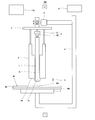
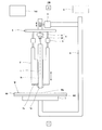
- FIG. 1 is a schematic diagram showing a schematic configuration of the friction stir welding apparatus according to the first embodiment.
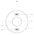
- FIG. 2 is a schematic diagram showing a schematic configuration of a tip end surface (lower end surface) of a pin member and a shoulder member in the friction stir welding apparatus shown in FIG.
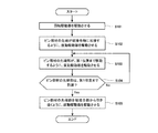
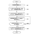
- FIG. 3 is a flowchart showing an example of the operation of the friction stir welding apparatus according to the first embodiment.
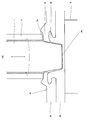
- FIG. 4 is a schematic diagram showing a main part of the friction stir welding apparatus according to the first embodiment, and shows a state where friction stir welding is being performed.
- FIG. 5 is a schematic diagram illustrating a schematic configuration of a friction stir welding apparatus according to a first modification of the first embodiment.
- FIG. 6 is a schematic diagram illustrating a schematic configuration of a friction stir welding apparatus according to a second modification of the first embodiment.
- FIG. 7 is a flowchart showing an example of the operation of the friction stir welding apparatus according to the second embodiment.
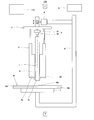
- FIG. 8 is a schematic diagram illustrating a schematic configuration of the friction stir welding apparatus according to the third embodiment.
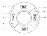
- FIG. 9 is a schematic diagram showing a schematic configuration of the distal end surfaces (lower end surfaces) of the pin member and the shoulder member in the friction stir welding apparatus shown in FIG.
- the friction stir welding apparatus includes a pin member formed in a columnar shape and configured to be rotatable around an axis and to advance and retreat in a direction along the axis, and a cylindrical member.
- a pin member is inserted therein, a shoulder member configured to be able to advance and retreat in a direction along the axis, a rotation driver for rotating the pin member around the axis, and a pin
- a linear drive for moving the member and the shoulder member forward and backward along the axis, and a control device, a first marking is formed on the distal end surface of the shoulder member, the control device rotates the pin member, And controlling the linear drive and the rotary drive so that the tip of the pin member presses the portion to be welded of the workpiece while the shoulder member is not rotating (A).
- the tip of the pin member may be formed to protrude from the tip surface of the shoulder member.
- FIG. 1 is a schematic diagram showing a schematic configuration of the friction stir welding apparatus according to the first embodiment.
- FIG. 2 is a schematic diagram showing a schematic configuration of a tip end surface (lower end surface) of a pin member and a shoulder member in the friction stir welding apparatus shown in FIG.
- the friction stir welding apparatus 100 includes a pin member 1, a shoulder member 2, a tool fixing device 3, a linear motion drive 4, a rotary drive 5, a backing support member 6, and the like. , A backing member 7, a robot 8, and a control device 110, and are configured to soften a joint portion Wa of a joint object W by frictional heat and join the joints.
- the workpiece W is composed of a plate-shaped first member W1 and a plate-shaped second member W2.
- the first member W1 may use at least one of a metal material (for example, aluminum), a thermoplastic (for example, polyamide), and a fiber-reinforced plastic (for example, carbon fiber-reinforced plastic).
- the member W2 may use a metal material (for example, steel) different from the first member W1.
- the configuration in which the workpiece W is composed of the plate-shaped first member W1 and the plate-shaped second member W2 is adopted, but the invention is not limited to this.
- the shape of W (first member W1 and second member W2) is arbitrary, and may be, for example, a rectangular parallelepiped shape or an arc shape.
- the pin member 1, the shoulder member 2, the tool fixing device 3, the linear motion driving device 4, and the rotation driving device 5 are provided on an upper part of a backing support member 6 composed of a C-type gun (C-type frame). .
- a backing member 7 is provided below the backing support member 6.
- the pin member 1 and the shoulder member 2 and the backing member 7 are attached to the backing support member 6 at positions facing each other.
- the backing support member 6 is attached to the tip of the robot 8.
- a robot of a horizontal articulated type, a vertical articulated type, or the like can be employed.
- the friction stir welding apparatus 100 according to the first embodiment is not limited to the case where the apparatus is applied to the robot 8.
- known processing such as an NC machine tool, a large C frame, and an automatic riveter may be used. It may be applied to equipment for use.
- the backing support member 6 is configured by a C-shaped gun, but is not limited to this.
- the backing support member 6 is configured to support the pin member 1 and the shoulder member 2 so as to be able to advance and retreat, and to support the backing member 7 at a position facing the pin member 1 and the shoulder member 2. It may be.
- the backing member 7 is formed in a flat plate shape, and is configured to support the workpiece W.
- the configuration of the backing member 7 is not particularly limited as long as it can appropriately support the workpiece W so that friction stir welding can be performed.
- the backing member 7 may be configured such that, for example, a plurality of backing members having various shapes are separately prepared and can be replaced according to the shape of the workpiece W.
- the pin member 1 and the shoulder member 2 are supported by a tool fixing device 3, and are configured to be driven up and down in a vertical direction by a linear motion driver 4.
- a linear motion driver 4 for example, an electric motor (servo motor) and a ball screw or a linear guide may be used, or an air cylinder or the like may be used.
- the pin member 1 is formed in a substantially columnar shape, and is configured to be rotatable around the axis Xr of the pin member 1 by the rotation driver 5.
- the rotation driver 5 has a motor 51 and a transmission mechanism 52 that transmits the rotation of the motor 51 to the pin member 1.
- the motor 51 for example, an electric motor (servo motor) may be used.
- the transmission mechanism 52 is configured not to transmit the rotation drive of the motor 51 to the shoulder member 2.
- a rotation transmission mechanism using a known gear or the like may be used.
- the transmission mechanism 52 mechanically transmits the rotation drive from the motor 51 only to the pin member 1, and transmits the rotation drive from the motor 51 to the shoulder member 2.
- the present invention is not limited to this.
- the transmission mechanism 52 employs a configuration in which the rotation drive from the motor 51 is electrically transmitted only to the pin member 1 and the rotation drive from the motor 51 is not transmitted to the shoulder member 2. Is also good.
- “electrically” may be a mode in which the transmission mechanism 52 does not transmit the rotation drive from the motor 51 to the shoulder member 2 because power (current) is not supplied to the transmission mechanism 52.
- control device 110 when control device 110 outputs an electric signal (control signal) for inhibiting operation to shoulder member 2 from transmission mechanism 52, transmission mechanism 52 does not transmit the rotation drive from motor 51 to shoulder member 2. It may be.
- the transmission mechanism 52 is configured to transmit the rotational drive from the motor 51 to the shoulder member 2 as well, the transmission mechanism 52 has a mechanism for releasing the engagement of the gears and the like, so that the May not be transmitted. Further, for example, the transmission mechanism 52 may include a mechanism for stopping rotation of a gear or the like, so that the rotation drive from the motor 51 is not transmitted to the shoulder member 2.
- the shoulder member 2 is formed in a substantially cylindrical shape having a hollow, and the pin member 1 is inserted into the hollow of the shoulder member 2. Further, in the first embodiment, pin member 1 and shoulder member 2 are arranged such that distal end surface 1a of pin member 1 protrudes beyond distal end surface 2a of shoulder member 2. Specifically, the distal end surface 1a of the pin member 1 is disposed so as to protrude from the distal end surface 2a of the shoulder member 2 by a predetermined first projection amount H.
- the first protrusion amount can be set in advance by an experiment or the like.
- the to-be-joined part Wa is joined by changing the amount of projection of the tip surface 1a of the pin member 1 from the tip surface 2a of the shoulder member 2 (hereinafter referred to as the amount of projection of the tip portion of the pin member 1).
- the joining strength of the joined portions Wa to be joined is measured, and a graph showing the relationship between the amount of protrusion of the distal end portion of the pin member 1 and the joining strength of the joined portions Wa is created.
- a protrusion amount that is equal to or more than a predetermined bonding strength (for example, a strength satisfying the standard of JIS # 3140) may be calculated, and the calculated protrusion amount may be set as the first protrusion amount H.
- a first stamp 101 is formed on the tip end surface 2 a of the shoulder member 2.
- the first inscription 101 may be, for example, at least one of a character, a graphic, a symbol, and a three-dimensional shape.
- the first inscription 101 has a square shape and a character shape of OK, and is formed at two positions on the distal end surface 2 a of the shoulder member 2.
- the pin member 1 and the shoulder member 2 are configured to be movable forward and backward by the linear motion driver 4, but the present invention is not limited to this.
- a mode in which the pin member 1 and the shoulder member 2 are configured to be able to move forward and backward independently of each other may be adopted.
- the control device 110 includes a processor such as a microprocessor and a CPU, a storage device such as a ROM and a RAM, and a clock device having a calendar function (not shown).
- the storage device stores information such as a basic program and various fixed data.
- the arithmetic processing unit reads and executes software such as a basic program stored in the storage device, and controls various operations of the linear drive unit 4, the rotation drive unit 5, and the robot 8.
- the control device 110 may be configured by a single control device 110 that performs centralized control, or may be configured by a plurality of control devices 110 that perform distributed control in cooperation with each other. Further, the control device 110 may be configured by a microcomputer, or may be configured by an MPU, a PLC (Programmable Logic Controller), a logic circuit, or the like.
- a microcomputer or may be configured by an MPU, a PLC (Programmable Logic Controller), a logic circuit, or the like.
- FIG. 3 is a flowchart showing an example of the operation of the friction stir welding apparatus according to the first embodiment.
- FIG. 4 is a schematic diagram showing a main part of the friction stir welding apparatus according to the first embodiment, and shows a state where friction stir welding is being performed.
- the control device 110 drives the rotation driver 5 to rotate the pin member 1 at a predetermined rotation speed (for example, 500 to 3000 rpm) (step S101).
- the control device 110 drives the linear motion driver 4 while rotating the pin member 1 and not rotating the shoulder member 2 to advance the pin member 1 and the shoulder member 2, and The distal end surface 1a of the member 1 is brought into contact with the portion Wa of the workpiece W (step S102).
- control device 110 drives the linear motion driver 4 so that the distal end of the pin member 1 moves to a predetermined first position set in advance (step S103). At this time, the control device 110 controls the linear motion driver 4 so that the pin member 1 presses the workpiece W with a predetermined pressing force (for example, 4 kN to 70 kN).
- a predetermined pressing force for example, 4 kN to 70 kN.
- the position information of the distal end of the pin member 1 is detected by a position detector (encoder) provided in the linear motion driver 4 or a position detector that detects the amount of movement of the pin member 1, and the control device Output to 110.
- the first position refers to a position where the first engraved mark 101 is marked on the portion Wa to be welded of the workpiece W when the friction stir welding apparatus 100 is in a normal state.
- the first position is greater than 0% when the surface of the second member W2 that contacts the first member W1 is 0% and the surface of the second member W2 that contacts the backing member 7 is 100%. , And can be arbitrarily set between less than 100%.
- the first position is preferably closer to the surface of the second member W2 that contacts the backing member 7, and may be 25% or more, or 50% or more. It may be 75% or more, 80% or more, 90% or more, or 95% or more.
- the pin member 1 comes into contact with the portion Wa to be welded of the workpiece W, and frictional heat is generated by the friction between the distal end portion of the pin member 1 and the portion Wa to be welded.
- the portion Wa is softened and plastic flow occurs.
- the distal end of the pin member 1 is press-fitted into the portion to be joined Wa, so that the second softened portion 42, which is the softened portion of the second member W2, is turned into the first member W1.
- the first softened portion 41 which is the softened portion of the first portion.
- the friction stir welding apparatus 100 is configured such that the shoulder member 2 does not rotate and only the pin member 1 rotates.
- the first softened portion 41 which has been pushed away by the press-fitting of the distal end portion of the pin member 1, comes into contact with the distal end surface 2a of the shoulder member 2, and the first stamp 101 is marked.
- the friction stir welding device 100 is not in a normal state, such as when the tip of the pin member 1 is worn or when the linear motion drive 4 or the like has a problem, Even if the linear drive 4 is controlled so that the tip of the pin member 1 reaches the first position, the tip of the pin member 1 cannot reach the first position.
- the volume of the first softened portion 41 and the second softened portion 42 to be extruded is reduced as compared with a normal case by the press-fitting of the distal end portion of the pin member 1, and the pushed first softened portion 41 and the shoulder are softened.
- the contact of the member 2 with the distal end surface 2a becomes insufficient.
- the first engraved mark 101 is not sufficiently stamped on the portion Wa to be joined of the article W to be joined.
- the control device 110 determines whether or not the distal end of the pin member 1 has reached the first position based on the positional information of the distal end (the distal end surface) of the pin member 1 detected by a position detector (not shown). Is determined (step S104). When the control device 110 determines that the distal end of the pin member 1 has not reached the first position (No in step S104), the control device 110 continues until the distal end of the pin member 1 reaches the first position. Each processing of steps S103 to S104 is executed. On the other hand, when the control device 110 determines that the tip end of the pin member 1 has reached the first position (Yes in step S104), the control device 110 executes the process of step S105.
- step S105 the control device 110 pulls out the distal end portion 1a of the pin member 1 from the portion Wa to be joined while rotating the pin member 1 and not rotating the shoulder member 2 (the pin member 1 and the shoulder member 1).
- the linear motion driver 4 is driven so that the tip of the workpiece 2 is separated from the surface of the workpiece W).
- the control device 110 stops the rotation driver 5 so as to stop the rotation of the pin member 1, and ends the program.
- the control device 110 may be configured to start joining of the next joint Wa without stopping the rotation of the pin member 1. .
- the second softened portion 42 of the second member W2 becomes An anchor effect is obtained in which the first member W1 enters the first softened portion 41, the strength against tensile shear increases, and the peel strength relatively increases.
- the shoulder member 2 is configured not to rotate, and the control device 110 moves the tip end of the pin member 1 to the first position. It is configured to drive the linear motion driver 4.
- the friction stir welding apparatus 100 is not in a normal state, for example, when the tip of the pin member 1 is worn, or when the position detector or the like of the linear drive 4 has a problem. In this case, even if the linear motion driver 4 is controlled so that the tip of the pin member 1 reaches the first position, the tip of the pin member 1 cannot reach the first position.
- the volume of the first softened portion 41 and the second softened portion 42 to be extruded is reduced as compared with a normal case by the press-fitting of the distal end portion of the pin member 1, and the pushed first softened portion 41 and the shoulder The contact of the member 2 with the distal end surface 2a becomes insufficient. As a result, the first engraved mark 101 is not sufficiently stamped on the portion Wa to be joined of the article W to be joined.
- the friction stir welding apparatus according to the first modification of the first embodiment further includes an adjuster configured to change a length dimension of the distal end portion of the pin member protruding from the distal end surface of the shoulder member.
- the adjuster may be configured to move the pin member forward and backward with respect to the shoulder member.
- FIG. 5 is a schematic diagram showing a schematic configuration of a friction stir welding apparatus according to a first modification of the first embodiment.
- the friction stir welding apparatus 100 according to the first modification has the same basic configuration as the friction stir welding apparatus 100 according to the first embodiment, but a shoulder member at the tip end of the pin member 1. 2 in that it further includes an adjuster 9 that is configured to change the length dimension protruding from the distal end surface 2a.
- the adjuster 9 is configured to move the pin member 1 forward and backward with respect to the shoulder member 2.
- a linear actuator may be used, an air cylinder or the like may be used, or an electric motor (servo motor) and a ball screw or a linear guide may be used.
- the friction stir welding apparatus 100 of the first modification includes the adjuster 9 configured to change the length of the distal end portion of the pin member 1 protruding from the distal end surface 2a of the shoulder member 2. ing.
- the amount of protrusion of the pin member 1 can be freely changed as appropriate according to the material (material) or thickness of the workpiece, and the bonding strength of the workpiece Wa can be changed.
- the adjuster is configured to move the shoulder member forward and backward with respect to the pin member.
- FIG. 6 is a schematic diagram showing a schematic configuration of a friction stir welding apparatus according to a second modification of the first embodiment.
- the friction stir welding apparatus 100 according to the second modification has the same basic configuration as the friction stir welding apparatus 100 according to the first modification of the first embodiment.
- the difference is that the shoulder member 2 is configured to advance and retreat with respect to 1.
- the friction stir welding apparatus includes a pin member that is formed in a columnar shape, and is configured to be rotatable around an axis and to advance and retreat in a direction along the axis.
- a pin member is inserted therein, a shoulder member configured to be able to advance and retreat in a direction along the axis, a rotation driver for rotating the pin member around the axis, and a pin
- a linear drive for moving the member and the shoulder member forward and backward along the axis, and a control device a first marking is formed on the distal end surface of the shoulder member, the control device rotates the pin member,
- the linear drive and the rotary drive are controlled so that the tip of the pin member presses the portion to be welded of the workpiece in a state where the shoulder member is not rotated (A)
- So that the first stamp is marked on the part to be joined
- the friction stir welding apparatus according to the second embodiment has the same configuration as the friction stir welding apparatus according to the first embodiment, and thus a detailed description thereof will be omitted.
- FIG. 7 is a flowchart showing an example of the operation of the friction stir welding apparatus according to the second embodiment.
- the worker places the workpiece W on the upper surface of the backing member 7.
- the operator operates the input device (not shown) to input the execution of the joining of the workpiece W to the control device 110.
- the control device 110 drives the rotation driver 5 to rotate the pin member 1 at a predetermined rotation speed (for example, 500 to 3000 rpm) (step S201).
- a predetermined rotation speed for example, 500 to 3000 rpm
- the control device 110 drives the linear motion driver 4 while rotating the pin member 1 and not rotating the shoulder member 2 to advance the pin member 1 and the shoulder member 2, and The distal end surface 1a of the member 1 is brought into contact with the portion Wa to be joined of the object W (step S202).
- control device 110 drives the linear motion driver 4 so that the tip end of the pin member 1 is press-fitted into the portion Wa of the workpiece W (step S203). At this time, the control device 110 controls the linear motion driver 4 so that the pin member 1 presses the workpiece W with a predetermined pressing force (for example, 4 kN to 70 kN).
- a predetermined pressing force for example, 4 kN to 70 kN.
- the pin member 1 rotates and comes into contact with the portion Wa to be joined of the article W to be joined, and friction between the tip end of the pin member 1 and the portion Wa to be joined generates frictional heat, so that the article W Is softened, and plastic flow occurs.
- the second softened portion 42 that is the softened portion of the second member W2 becomes the first softened portion of the first member W1. It enters the softened portion 41.
- control device 110 acquires, from the clock unit, the time elapsed since the driving of the linear motion driver 4 in step S203 (step S204).
- control device 110 determines whether or not the time acquired in step S204 (the time elapsed since the drive of the linear motion driver 4) has exceeded a preset first time (step S205). ).
- the first time when the friction stir welding apparatus 100 is in a normal state, the front ends of the pin member 1 and the shoulder member 2 until the first engraved mark 101 is marked on the welded portion Wa of the workpiece W. This is the time it takes for the part to move.
- the first time is a time required for the tip of the pin member 1 to reach the first position.
- the first time can be set in advance by an experiment or the like.
- control device 110 waits until the time acquired in step S204 has passed the first time. The processing of steps S204 and S205 is executed. On the other hand, when it is determined that the time acquired in step S204 has passed the first time (Yes in step S205), control device 110 executes the process of step S206.
- step S206 the control device 110 pulls out the distal end portion 1a of the pin member 1 from the portion to be joined Wa while rotating the pin member 1 and not rotating the shoulder member 2 (the pin member 1 and the shoulder member 1).
- the linear motion driver 4 is driven so that the tip of the workpiece 2 is separated from the surface of the workpiece W).
- the control device 110 stops the rotation driver 5 so as to stop the rotation of the pin member 1, and ends the program.
- the control device 110 may be configured to start joining of the next joint Wa without stopping the rotation of the pin member 1. .
- the friction stir welding apparatus 100 according to the second embodiment configured as described above has the same operation and effect as the friction stir welding apparatus 100 according to the first embodiment.
- the friction stir welding apparatus according to the third embodiment is different from the friction stir welding apparatus according to the first embodiment (including a modification) or the second embodiment in that a concave portion is formed on the tip end surface of the shoulder member.
- the second mark is formed on the bottom surface of the concave portion.
- FIG. 8 is a schematic diagram illustrating a schematic configuration of the friction stir welding apparatus according to the third embodiment.
- FIG. 9 is a schematic diagram showing a schematic configuration of the distal end surfaces (lower end surfaces) of the pin member and the shoulder member in the friction stir welding apparatus shown in FIG. In FIG. 9, hatching is shown to facilitate understanding of the bottom surface of the concave portion.
- the friction stir welding apparatus 100 according to the third embodiment has the same basic configuration as the friction stir welding apparatus 100 according to the first embodiment. The difference is that a concave portion 20 is formed on the surface 2a, and a second mark 102 is formed on the bottom surface of the concave portion 20. In the third embodiment, the concave portions 20 are formed at two places.
- the depth dimension of the concave portion 20 can be set in advance by an experiment or the like.
- the depth dimension of the concave portion 20 may be, for example, 0.5 mm or more because wear of the tip of the pin member 1 is detected at an early stage, and a viewpoint of detecting a time when maintenance such as replacement of the pin member 1 is performed. Therefore, it may be 3.0 mm.
- the second inscription 102 may be, for example, at least one of a character, a figure, a symbol, and a three-dimensional shape, and may be different from the first inscription 101.
- the second engraving 102 has a square shape and a character shape of OK2.
- the friction stir welding apparatus 100 according to the third embodiment configured as described above has the same operation and effect as the friction stir welding apparatus 100 according to the first embodiment.
- the concave portion 20 is formed on the distal end surface 2a of the shoulder member 2, and the second engraved mark 102 is formed on the bottom surface of the concave portion 20.
- the first engraved mark 101 and the second engraved mark 102 are marked on the portion Wa to be bonded of the workpiece W, it is possible to accurately determine that the bonding strength of the portion Wa to be bonded is sufficient. It is possible to determine that the maintenance is not required, for example, when the tip of the pin member 1 is not worn.
- the first stamp 101 is marked on the portion Wa to be joined of the workpiece W and the second stamp 102 is not marked, it is accurately determined that the joining strength of the portion Wa is sufficient. In addition to the determination, it is possible to determine that the maintenance needs to be performed.
- the friction stir welding apparatus and the operation method thereof of the present invention have a simple configuration and, compared to a conventional friction stir welding apparatus, can accurately determine whether or not a predetermined joining strength has been reached, Useful.
Landscapes
- Engineering & Computer Science (AREA)
- Mechanical Engineering (AREA)
- Pressure Welding/Diffusion-Bonding (AREA)
Abstract
ピン部材(1)と、先端面(2a)に第1刻印(101)が形成されている、ショルダ部材(2)と、直動駆動器(4)と、回転駆動器(5)と、ピン部材(1)を回転させた状態で、ピン部材(1)の先端部が被接合物(W)の被接合部(Wa)を押圧するように、直動駆動器(4)及び回転駆動器(5)を制御する(A)と、被接合物(W)の被接合部(Wa)に第1刻印(101)が印される位置である第1位置まで、ピン部材(1)の先端部が到達するように、直動駆動器(4)及び回転駆動器(5)を制御する(B)と、(B)の後、ピン部材(1)を回転させた状態で、ピン部材(1)の先端部を被接合部(Wa)から引き抜くように、直動駆動器(4)及び回転駆動器(5)を制御する(C)と、を実行するように構成されている制御装置(110)と、を備える、摩擦攪拌接合装置。
Description
本発明は、摩擦攪拌接合装置及びその運転方法に関する。
少なくとも2枚の部材を重ね合わせて、回転ツールを一方の部材に加圧して押し込み、摩擦攪拌することにより、接合する装置において、接合強度の良否を判定する接合状態検出手段を具備する加工管理装置が知られている(例えば、特許文献1参照)。特許文献1に開示されている加工管理装置では、接合状態検出手段が、回転ツールの先端部に設けられている突出部の先端位置に基づいて、一方の部材の接合部の板厚減少量を算出し、算出された板厚減少量に基づいて接合強度の良否を判定する。
しかしながら、特許文献1に開示されている加工管理装置では、突出部の先端位置を、回転ツールを昇降させるためのモータのエンコーダの出力に基づいて演算している。このめ、突出部が摩耗したような場合には、エンコーダから得られた突出部の先端位置と、実際の突出部の先端位置と、では、誤差が生じ、接合強度の良否判定が正確とはならないおそれがあり、未だ改善の余地があった。
本発明は、上記課題を解決するためになされたものであって、簡易な構成で、従来の摩擦攪拌接合装置に比して、所定の接合強度に達しているか否かを正確に判定することができ得る、摩擦攪拌接合装置及びその運転方法を提供することを目的とする。
上記従来の課題を解決するために、本発明に係る摩擦攪拌接合装置は、円柱状に形成され、軸線周りの回転と該軸線に沿った方向への進退移動とが可能なように構成されているピン部材と、円筒状に形成され、前記ピン部材が内部に挿通されており、前記軸線に沿った方向への進退移動が可能なように構成されているショルダ部材と、前記ピン部材を前記軸線周りに回転させる回転駆動器と、前記ピン部材及び前記ショルダ部材を前記軸線に沿って進退移動させる直動駆動器と、制御装置と、を備え、前記ショルダ部材の先端面には、第1刻印が形成され、前記制御装置は、前記ピン部材を回転させ、かつ、前記ショルダ部材を回転させていない状態で、前記ピン部材の先端部が被接合物の被接合部を押圧するように、前記直動駆動器及び前記回転駆動器を制御する(A)と、前記ピン部材の先端部が第1位置にまで到達するように、前記直動駆動器及び前記回転駆動器を制御する(B)と、前記(B)の後、前記ピン部材を回転させ、かつ、前記ショルダ部材を回転させていない状態で、前記ピン部材を前記被接合部から引き抜くように、前記直動駆動器及び前記回転駆動器を制御する(C)と、を実行するように構成されていて、前記第1位置は、前記ピン部材の先端部が当該位置まで到達することにより、前記被接合物の被接合部に前記第1刻印が印される位置である。
これにより、ピン部材が第1位置に到達すると、被接合物の被接合部に、第1刻印が印される。一方、ピン部材の先端部が摩耗しているような場合、又は直動駆動器等に不具合が生じているような場合等には、ピン部材が第1位置にまで到達しない。このため、ピン部材の圧入により押し出される軟化した部分の体積が、正常な場合に比して小さくなり、押し出された軟化した部分とショルダ部材の先端面との当接が不充分となり、被接合物の被接合部には、第1刻印が充分に印されない。したがって、第1刻印が印されているか否かで、被接合部が所定の接合強度に達しているか否かを正確に判定することができ得る。
また、本発明に係る摩擦攪拌接合装置の運転方法は、被接合物を摩擦熱で軟化させることにより接合する摩擦攪拌接合装置の運転方法であって、前記摩擦攪拌接合装置は、円柱状に形成され、軸線周りの回転と該軸線に沿った方向への進退移動とが可能なように構成されているピン部材と、円筒状に形成され、前記ピン部材が内部に挿通されており、前記軸線に沿った方向への進退移動が可能なように構成されているショルダ部材と、前記ピン部材を前記軸線周りに回転させる回転駆動器と、前記ピン部材及び前記ショルダ部材を前記軸線に沿って進退移動させる直動駆動器と、を備え、前記ショルダ部材の先端面には、第1刻印が形成され、前記ピン部材を回転させ、かつ、前記ショルダ部材を回転させていない状態で、前記ピン部材の先端部が前記被接合物の被接合部を押圧するように、前記直動駆動器及び前記回転駆動器が動作する(A)と、前記ピン部材の先端部が第1位置にまで到達するように、前記直動駆動器及び前記回転駆動器が動作する(B)と、前記(B)の後、前記ピン部材を回転させ、かつ、前記ショルダ部材を回転させていない状態で、前記ピン部材を前記被接合部から引き抜くように、前記直動駆動器及び前記回転駆動器が動作する(C)と、を備え、前記第1位置は、前記ピン部材の先端部が当該位置まで到達することにより、前記被接合物の被接合部に前記第1刻印が印される位置である。
これにより、ピン部材が第1位置に到達すると、被接合物の被接合部に、第1刻印が印される。一方、ピン部材の先端部が摩耗しているような場合、又は直動駆動器等に不具合が生じているような場合等には、ピン部材が第1位置にまで到達しない。このため、ピン部材の圧入により押し出される軟化した部分の体積が、正常な場合に比して小さくなり、押し出された軟化した部分とショルダ部材の先端面との当接が不充分となり、被接合物の被接合部には、第1刻印が充分に印されない。したがって、第1刻印が印されているか否かで、被接合部が所定の接合強度に達しているか否かを正確に判定することができ得る。
本発明の上記目的、他の目的、特徴、及び利点は、添付図面参照の下、以下の好適な実施形態の詳細な説明から明らかにされる。
本発明に係る摩擦攪拌接合装置及びその運転方法によれば、簡易な構成で、従来の摩擦攪拌接合装置に比して、所定の接合強度に達しているか否かを正確に判定することができ得る。
以下、本発明の好ましい実施の形態を、図面を参照しながら説明する。なお、以下では全ての図を通じて同一又は相当する要素には同一の参照符号を付して、その重複する説明を省略する。また、全ての図面において、本発明を説明するために必要となる構成要素を抜粋して図示しており、その他の構成要素については図示を省略している場合がある。さらに、本発明は以下の実施の形態に限定されない。
(実施の形態1)
本実施の形態1に係る摩擦攪拌接合装置は、円柱状に形成され、軸線周りの回転と該軸線に沿った方向への進退移動とが可能なように構成されているピン部材と、円筒状に形成され、ピン部材が内部に挿通されており、軸線に沿った方向への進退移動が可能なように構成されているショルダ部材と、ピン部材を軸線周りに回転させる回転駆動器と、ピン部材及びショルダ部材を軸線に沿って進退移動させる直動駆動器と、制御装置と、を備え、ショルダ部材の先端面には、第1刻印が形成され、制御装置は、ピン部材を回転させ、かつ、ショルダ部材を回転させていない状態で、ピン部材の先端部が被接合物の被接合部を押圧するように、直動駆動器及び回転駆動器を制御する(A)と、ピン部材の先端部が第1位置にまで到達するように、直動駆動器及び回転駆動器を制御する(B)と、(B)の後、ピン部材を回転させ、かつ、ショルダ部材を回転させていない状態で、ピン部材を被接合部から引き抜くように、直動駆動器及び回転駆動器を制御する(C)と、を実行するように構成されていて、第1位置は、ピン部材の先端部が当該位置まで到達することにより、被接合物の被接合部に第1刻印が印される位置である。
本実施の形態1に係る摩擦攪拌接合装置は、円柱状に形成され、軸線周りの回転と該軸線に沿った方向への進退移動とが可能なように構成されているピン部材と、円筒状に形成され、ピン部材が内部に挿通されており、軸線に沿った方向への進退移動が可能なように構成されているショルダ部材と、ピン部材を軸線周りに回転させる回転駆動器と、ピン部材及びショルダ部材を軸線に沿って進退移動させる直動駆動器と、制御装置と、を備え、ショルダ部材の先端面には、第1刻印が形成され、制御装置は、ピン部材を回転させ、かつ、ショルダ部材を回転させていない状態で、ピン部材の先端部が被接合物の被接合部を押圧するように、直動駆動器及び回転駆動器を制御する(A)と、ピン部材の先端部が第1位置にまで到達するように、直動駆動器及び回転駆動器を制御する(B)と、(B)の後、ピン部材を回転させ、かつ、ショルダ部材を回転させていない状態で、ピン部材を被接合部から引き抜くように、直動駆動器及び回転駆動器を制御する(C)と、を実行するように構成されていて、第1位置は、ピン部材の先端部が当該位置まで到達することにより、被接合物の被接合部に第1刻印が印される位置である。
また、本実施の形態1に係る摩擦攪拌接合装置では、ピン部材の先端部は、ショルダ部材の先端面から突出するように形成されていてもよい。
以下、本実施の形態1に係る摩擦攪拌接合装置の一例について、図1~図4を参照しながら詳細に説明する。
[摩擦攪拌接合装置の構成]
図1は、本実施の形態1に係る摩擦攪拌接合装置の概略構成を示す模式図である。図2は、図1に示す摩擦攪拌接合装置におけるピン部材及びショルダ部材の先端面(下端面)の概略構成を示す模式図である。
図1は、本実施の形態1に係る摩擦攪拌接合装置の概略構成を示す模式図である。図2は、図1に示す摩擦攪拌接合装置におけるピン部材及びショルダ部材の先端面(下端面)の概略構成を示す模式図である。
図1に示すように、本実施の形態1に係る摩擦攪拌接合装置100は、ピン部材1、ショルダ部材2、工具固定器3、直動駆動器4、回転駆動器5、裏当て支持部材6、裏当て部材7、ロボット8、及び制御装置110を備えていて、被接合物Wの被接合部Waを摩擦熱で軟化させて、接合するように構成されている。
被接合物Wは、本実施の形態1においては、板状の第1部材W1と板状の第2部材W2で構成されている。第1部材W1は、金属材料(例えば、アルミニウム)、熱可塑性プラスチック(例えば、ポリアミド)、及び繊維強化プラスチック(例えば、炭素繊維強化プラスチック)のうち、少なくとも1つの材料を用いてもよく、第2部材W2は、第1部材W1とは異なる金属材料(例えば、鋼)を用いてもよい。
なお、本実施の形態1においては、被接合物Wを板状の第1部材W1と板状の第2部材W2で構成されている形態を採用したが、これに限定されず、被接合物W(第1部材W1及び第2部材W2)の形状は任意であり、例えば、直方体状であってもよく、円弧状に形成されていてもよい。
ピン部材1、ショルダ部材2、工具固定器3、直動駆動器4、及び回転駆動器5は、C型ガン(C型フレーム)で構成される裏当て支持部材6の上部に設けられている。また、裏当て支持部材6の下部には、裏当て部材7が設けられている。ピン部材1及びショルダ部材2と、裏当て部材7と、は互いに対向する位置で裏当て支持部材6に取り付けられている。裏当て支持部材6は、ロボット8の先端に取り付けられている。ロボット8としては、水平多関節型・垂直多関節型などのロボットを採用することができる。
なお、本実施の形態1に係る摩擦攪拌接合装置100は、ロボット8に適用される場合に限定されるものではなく、例えば、NC工作機械、大型のCフレーム、及びオートリベッター等の公知の加工用機器に適用してもよい。
また、本実施の形態1においては、裏当て支持部材6がC型ガンで構成されている形態を採用したが、これに限定されない。裏当て支持部材6は、ピン部材1及びショルダ部材2を進退移動可能に支持するとともに、ピン部材1及びショルダ部材2に対向する位置に裏当て部材7を支持することができれば、どのように構成されていてもよい。
裏当て部材7は、平板状に形成されていて、被接合物Wを支持するように構成されている。なお、裏当て部材7は、摩擦攪拌接合を実施できるように、被接合物Wを適切に支持することができるものであれば、その構成は特に限定されない。裏当て部材7は、例えば、複数の様々な形状を有する裏当て部材が別途準備され、被接合物Wの形状に応じて、交換できるように構成されていてもよい。
ピン部材1及びショルダ部材2は、工具固定器3により支持されており、直動駆動器4によって、上下方向に進退駆動されるように構成されている。直動駆動器4としては、例えば、電動モータ(サーボモータ)とボールネジ又はリニアガイド等を用いてもよく、エアシリンダ等を用いてもよい。
また、ピン部材1は、略円柱形に形成されていて、回転駆動器5により、ピン部材1の軸線Xr回りに回転可能に構成されている。回転駆動器5は、モータ51とモータ51の回転駆動をピン部材1に伝達する伝達機構52を有している。モータ51としては、例えば、電動モータ(サーボモータ)を用いてもよい。また、伝達機構52は、ショルダ部材2にモータ51の回転駆動を伝達しないように構成されている。伝達機構52としては、公知の歯車等による回転伝達機構を用いてもよい。
なお、本実施の形態1においては、図1に示すように、伝達機構52は、機械的に、ピン部材1のみにモータ51からの回転駆動を伝達し、ショルダ部材2には、モータ51からの回転駆動を伝達しないように構成されている形態を採用したが、これに限定されない。伝達機構52は、電気的に、ピン部材1のみにモータ51からの回転駆動を伝達し、ショルダ部材2には、モータ51からの回転駆動を伝達しないように構成されている形態を採用してもよい。
ここで、「電気的に」とは、伝達機構52に電力(電流)が供給されないことにより、伝達機構52が、ショルダ部材2にモータ51からの回転駆動が伝達しない態様であってもよい。また、制御装置110からショルダ部材2への作動を禁止する電気信号(制御信号)が伝達機構52出力されることにより、伝達機構52が、ショルダ部材2にモータ51からの回転駆動が伝達しない態様であってもよい。
なお、伝達機構52は、ショルダ部材2にも、モータ51からの回転駆動を伝達するように構成されているが、歯車等のかみ合いを解除させる機構を有することにより、ショルダ部材2にモータ51からの回転駆動が伝達されない態様であってもよい。また、例えば、伝達機構52は、歯車等の回転を停止させる機構を有することにより、ショルダ部材2にモータ51からの回転駆動が伝達されない態様であってもよい。
ショルダ部材2は、中空を有する略円筒状に形成されていて、ショルダ部材2の中空内には、ピン部材1が内挿されている。また、本実施の形態1においては、ピン部材1の先端面1aが、ショルダ部材2の先端面2aよりも突出するように、ピン部材1及びショルダ部材2が配置されている。具体的には、ピン部材1の先端面1aが、ショルダ部材2の先端面2aよりも、予め設定されている所定の第1突出量H分だけ突出するように配置されている。
ここで、第1突出量は、予め実験等により設定することができる。例えば、ピン部材1の先端面1aのショルダ部材2の先端面2aに対する突出量(以下、ピン部材1の先端部の突出量という)を変えて、被接合部Waを接合する。ついで、接合した被接合部Waの接合強度を測定して、ピン部材1の先端部の突出量と、被接合部Waの接合強度と、の関係示すグラフを作成する。そして、当該グラフから、所定の接合強度(例えば、JIS 3140の規格を満たす強度)以上となる突出量を算出して、当該算出した突出量を第1突出量Hとして設定してもよい。
また、図2に示すように、ショルダ部材2の先端面2aには、第1刻印101が形成されている。第1刻印101としては、例えば、文字、図形、記号、及び立体的形状のうち、少なくとも1つの形状で構成されていてればよい。本実施の形態1においては、第1刻印101は、四角形状と、OKという文字形状と、で構成されていて、ショルダ部材2の先端面2aの2ヶ所に形成されている。
なお、本実施の形態1においては、ピン部材1及びショルダ部材2が、直動駆動器4により、進退移動可能に構成されている形態を採用したが、これに限定されない。ピン部材1及びショルダ部材2が、それぞれ独立して、進退移動可能に構成されている形態を採用してもよい。
制御装置110は、マイクロプロセッサ、CPU等の演算処理器と、ROM、RAM等の記憶器と、カレンダー機能を有する時計器と、を備えている(図示せず)。記憶器には、基本プログラム、各種固定データ等の情報が記憶されている。演算処理器は、記憶器に記憶された基本プログラム等のソフトウェアを読み出して実行することにより、直動駆動器4、回転駆動器5、及びロボット8の各種動作を制御する。
なお、制御装置110は、集中制御する単独の制御装置110によって構成されていてもよいし、互いに協働して分散制御する複数の制御装置110によって構成されていてもよい。また、制御装置110は、マイクロコンピュータで構成されていてもよく、MPU、PLC(Programmable Logic Controller)、論理回路等によって構成されていてもよい。
[摩擦攪拌接合装置の動作(摩擦攪拌接合装置の運転方法)及び作用効果]
次に、本実施の形態1に係る摩擦攪拌接合装置1の動作(運転方法)及び作用効果について、図1~図4を参照しながら説明する。なお、以下の動作は、制御装置110の演算処理器が、記憶器に格納されているプログラムを読み出すことにより実行される。
次に、本実施の形態1に係る摩擦攪拌接合装置1の動作(運転方法)及び作用効果について、図1~図4を参照しながら説明する。なお、以下の動作は、制御装置110の演算処理器が、記憶器に格納されているプログラムを読み出すことにより実行される。
図3は、本実施の形態1に係る摩擦攪拌接合装置の動作の一例を示すフローチャートである。図4は、本実施の形態1に係る摩擦攪拌接合装置の要部を示す模式図であり、摩擦攪拌接合を実行している状態を示す。
まず、作業者が裏当て部材7の上面に被接合物Wを載置する。ついで、作業者が入力器(図示せず)を操作して、制御装置110に被接合物Wの接合実行を入力する。
すると、図3に示すように、制御装置110は、回転駆動器5を駆動させて、ピン部材1を所定の回転数(例えば、500~3000rpm)で回転させる(ステップS101)。ついで、制御装置110は、ピン部材1を回転させ、かつ、ショルダ部材2を回転していない状態で、直動駆動器4を駆動させて、ピン部材1及びショルダ部材2を進行させて、ピン部材1の先端面1aを被接合物Wの被接合部Waに当接させる(ステップS102)。
次に、制御装置110は、ピン部材1の先端部が予め設定されている所定の第1位置まで移動するように、直動駆動器4を駆動させる(ステップS103)。このとき、制御装置110は、ピン部材1が予め設定された所定の押圧力(例えば、4kN~70kN)で被接合物Wを押圧するように、直動駆動器4を制御する。
なお、所定の回転数及び所定の押圧力は、予め実験等により、適宜設定することができる。また、ピン部材1の先端部の位置情報は、直動駆動器4に設けられている位置検出器(エンコーダ)、又はピン部材1の移動量を検出する位置検出器により検出されて、制御装置110に出力される。
ここで、第1位置は、摩擦攪拌接合装置100が正常な状態のときに、被接合物Wの被接合部Waに第1刻印101が印される位置をいう。また、第1位置は、第2部材W2の第1部材W1と当接する面を0%とし、第2部材W2の裏当て部材7と当接する面を100%とした場合に、0%より大きく、かつ、100%未満の間で任意に設定することができる。
なお、接合強度を向上させる観点から、第1位置は、第2部材W2の裏当て部材7と当接する面に近い方がよく、25%以上であってもよく、50%以上であってもよく、75%以上であってもよく、80%以上であってもよく、90%以上であってもよく、95%以上であってもよい。
これにより、ピン部材1が、被接合物Wの被接合部Waに当接し、ピン部材1の先端部と被接合部Waとの摩擦により、摩擦熱が発生し、被接合物Wの被接合部Waが軟化されて、塑性流動が生じる。
そして、図4に示すように、ピン部材1の先端部が、被接合部Waの内部に圧入されることにより、第2部材W2の軟化部分である第2軟化部分42が、第1部材W1の軟化部分である第1軟化部分41に入り込む(突き刺さる)。
このとき、本実施の形態1に係る摩擦攪拌接合装置100では、ショルダ部材2が回転せず、ピン部材1のみが回転するように構成されている。これにより、ピン部材1の先端部の圧入により押しのけられた、第1軟化部分41が、ショルダ部材2の先端面2aと当接して、第1刻印101が印される。
なお、ピン部材1の先端部が摩耗しているような場合、又は直動駆動器4等に不具合が生じているような場合等、摩擦攪拌接合装置100が正常な状態ではない場合には、ピン部材1の先端部を第1位置まで到達するように、直動駆動器4を制御しても、ピン部材1の先端部が第1位置まで到達することができない。
このため、ピン部材1の先端部の圧入により、押し出される第1軟化部分41及び第2軟化部分42の体積が、正常な場合に比して小さくなり、押し出された第1軟化部分41とショルダ部材2の先端面2aとの当接が不充分となる。これにより、被接合物Wの被接合部Waには、第1刻印101が充分に印されない。
したがって、第1刻印101が、被接合部Waに印されているか否かを検知することで、被接合部Waが、所定の接合強度に達しているか否かを正確に判定することができ得る。
次に、制御装置110は、図示されない位置検知器が検知した、ピン部材1の先端部(先端面)の位置情報を基に、ピン部材1の先端部が、第1位置まで到達したか否かを判定する(ステップS104)。制御装置110は、ピン部材1の先端部が、第1位置まで到達していないと判定した場合(ステップS104でNo)には、ピン部材1の先端部が、第1位置まで到達するまで、ステップS103~ステップS104の各処理を実行する。一方、制御装置110は、ピン部材1の先端部が、第1位置まで到達していると判定した場合(ステップS104でYes)には、ステップS105の処理を実行する。
ステップS105では、制御装置110は、ピン部材1を回転させ、かつ、ショルダ部材2を回転させていない状態で、ピン部材1の先端部1aを被接合部Waから引き抜く(ピン部材1及びショルダ部材2の先端部が被接合物Wの表面から離間する)ように、直動駆動器4を駆動させる。そして、制御装置110は、ピン部材1の先端部1aが、被接合部Waから引き抜かれると、ピン部材1の回転を停止するように、回転駆動器5を停止させて、本プログラムを終了する。なお、複数の被接合部Waを接合する場合には、制御装置110は、ピン部材1の回転を停止させずに、次の被接合部Waの接合を開始するように構成されていてもよい。
このように構成された、本実施の形態1に係る摩擦攪拌接合装置100では、被接合物Wに対して、摩擦攪拌接合を実行することにより、第2部材W2の第2軟化部分42が、第1部材W1の第1軟化部分41に入り込み、引張せん断に対する強度が高くなり、相対的に剥離強度も高くなるといったアンカー効果が得られる。
また、本実施の形態1に係る摩擦攪拌接合装置100では、ショルダ部材2が回転しないように構成され、かつ、制御装置110が、ピン部材1の先端部が第1位置まで移動するように、直動駆動器4を駆動させるように構成されている。
これにより、摩擦攪拌接合装置100が正常である場合には、ピン部材1の先端部の圧入により押しのけられた、第1軟化部分41が、ショルダ部材2の先端面2aと当接して、第1刻印101が印される。
なお、ピン部材1の先端部が摩耗しているような場合、又は直動駆動器4の位置検知器等に不具合が生じているような場合等、摩擦攪拌接合装置100が正常な状態ではない場合には、ピン部材1の先端部を第1位置まで到達するように、直動駆動器4を制御しても、ピン部材1の先端部が第1位置まで到達することができない。
このため、ピン部材1の先端部の圧入により、押し出される第1軟化部分41及び第2軟化部分42の体積が、正常な場合に比して小さくなり、押し出された第1軟化部分41とショルダ部材2の先端面2aとの当接が不充分となる。これにより、被接合物Wの被接合部Waには、第1刻印101が充分に印されない。
したがって、第1刻印101が、被接合部Waに印されているか否かを検知することで、被接合部Waが、所定の接合強度に達しているか否かを正確に判定することができ得る。
[変形例1]
次に、本実施の形態1に係る摩擦攪拌接合装置の変形例について、説明する。
次に、本実施の形態1に係る摩擦攪拌接合装置の変形例について、説明する。
本実施の形態1における変形例1の摩擦攪拌接合装置は、ピン部材の先端部における、ショルダ部材の先端面から突出する長さ寸法を変更するように構成されている、調整器をさらに備える。
また、本変形例1の摩擦攪拌接合装置では、調整器が、ショルダ部材に対して、ピン部材を進退させるように構成されていてもよい。
以下、本変形例1の摩擦攪拌接合装置の一例について、図5を参照しながら説明する。
図5は、本実施の形態1における変形例1の摩擦攪拌接合装置の概略構成を示す模式図である。
図5に示すように、本変形例1の摩擦攪拌接合装置100は、実施の形態1に係る摩擦攪拌接合装置100と基本的構成は同じであるが、ピン部材1の先端部における、ショルダ部材2の先端面2aから突出する長さ寸法を変更するように構成されている、調整器9をさらに備える点が異なる。本変形例1においては、調整器9は、ショルダ部材2に対して、ピン部材1を進退させるように構成されている。調整器9としては、例えば、直動アクチュエータで構成されていてもよく、エアシリンダ等を用いてもよく、又は電動モータ(サーボモータ)とボールネジ又はリニアガイド等を用いてもよい。
このように構成された、本変形例1の摩擦攪拌接合装置100であっても、実施の形態1に係る摩擦攪拌接合装置100と同様の作用効果を奏する。
また、本変形例1の摩擦攪拌接合装置100では、ピン部材1の先端部における、ショルダ部材2の先端面2aから突出する長さ寸法を変更するように構成されている、調整器9を備えている。これにより、被接合物の材料(材質)又は厚み寸法によって、適宜、ピン部材1の突出量を自由に変更することができ、被接合部Waの接合強度を変更することができる。
[変形例2]
本実施の形態1における変形例2の摩擦攪拌接合装置は、調整器は、ピン部材に対してショルダ部材を進退させるように構成されている。
本実施の形態1における変形例2の摩擦攪拌接合装置は、調整器は、ピン部材に対してショルダ部材を進退させるように構成されている。
以下、本変形例2の摩擦攪拌接合装置の一例について、図6を参照しながら説明する。
図6は、本実施の形態1における変形例2の摩擦攪拌接合装置の概略構成を示す模式図である。
図6に示すように、本変形例2の摩擦攪拌接合装置100は、実施の形態1における変形例1の摩擦攪拌接合装置100と基本的構成は同じであるが、調整器9が、ピン部材1に対してショルダ部材2を進退させるように構成されている点が異なる。
このように構成された、本変形例2の摩擦攪拌接合装置100であっても、実施の形態1における変形例1の摩擦攪拌接合装置100と同様の作用効果を奏する。
(実施の形態2)
本実施の形態2に係る摩擦攪拌接合装置は、円柱状に形成され、軸線周りの回転と該軸線に沿った方向への進退移動とが可能なように構成されているピン部材と、円筒状に形成され、ピン部材が内部に挿通されており、軸線に沿った方向への進退移動が可能なように構成されているショルダ部材と、ピン部材を軸線周りに回転させる回転駆動器と、ピン部材及びショルダ部材を軸線に沿って進退移動させる直動駆動器と、制御装置と、を備え、ショルダ部材の先端面には、第1刻印が形成され、制御装置は、ピン部材を回転させ、かつ、ショルダ部材を回転させていない状態で、ピン部材の先端部が被接合物の被接合部を押圧するように、直動駆動器及び回転駆動器を制御する(A)と、被接合物の被接合部に第1刻印が印されるように、予め設定されている所定の第1時間、直動駆動器及び回転駆動器を動作させる(B1)と、(B1)の後、ピン部材を回転させ、かつ、ショルダ部材を回転させていない状態で、ピン部材を被接合部から引き抜くように、直動駆動器及び回転駆動器を制御する(C)と、を実行するように構成されている。
本実施の形態2に係る摩擦攪拌接合装置は、円柱状に形成され、軸線周りの回転と該軸線に沿った方向への進退移動とが可能なように構成されているピン部材と、円筒状に形成され、ピン部材が内部に挿通されており、軸線に沿った方向への進退移動が可能なように構成されているショルダ部材と、ピン部材を軸線周りに回転させる回転駆動器と、ピン部材及びショルダ部材を軸線に沿って進退移動させる直動駆動器と、制御装置と、を備え、ショルダ部材の先端面には、第1刻印が形成され、制御装置は、ピン部材を回転させ、かつ、ショルダ部材を回転させていない状態で、ピン部材の先端部が被接合物の被接合部を押圧するように、直動駆動器及び回転駆動器を制御する(A)と、被接合物の被接合部に第1刻印が印されるように、予め設定されている所定の第1時間、直動駆動器及び回転駆動器を動作させる(B1)と、(B1)の後、ピン部材を回転させ、かつ、ショルダ部材を回転させていない状態で、ピン部材を被接合部から引き抜くように、直動駆動器及び回転駆動器を制御する(C)と、を実行するように構成されている。
以下、本実施の形態2に係る摩擦攪拌接合装置の一例について、図7を参照しながら説明する。なお、本実施の形態2に係る摩擦攪拌接合装置は、実施の形態1に係る摩擦攪拌接合装置と構成は同じであるため、その詳細な説明は省略する。
[摩擦攪拌接合装置の動作及び作用効果]
図7は、本実施の形態2に係る摩擦攪拌接合装置の動作の一例を示すフローチャートである。
図7は、本実施の形態2に係る摩擦攪拌接合装置の動作の一例を示すフローチャートである。
まず、実施の形態1に係る摩擦攪拌接合装置100と同様に、作業者が裏当て部材7の上面に被接合物Wを載置する。ついで、作業者が入力器(図示せず)を操作して、制御装置110に被接合物Wの接合実行を入力する。
すると、図7に示すように、制御装置110は、回転駆動器5を駆動させて、ピン部材1を所定の回転数(例えば、500~3000rpm)で回転させる(ステップS201)。ついで、制御装置110は、ピン部材1を回転させ、かつ、ショルダ部材2を回転させていない状態で、直動駆動器4を駆動させて、ピン部材1及びショルダ部材2を進行させて、ピン部材1の先端面1aを被接合物Wの被接合部Waに当接させる(ステップS202)。
次に、制御装置110は、ピン部材1の先端部が被接合物Wの被接合部Wa内に圧入するように、直動駆動器4を駆動させる(ステップS203)。このとき、制御装置110は、ピン部材1が予め設定された所定の押圧力(例えば、4kN~70kN)で被接合物Wを押圧するように、直動駆動器4を制御する。
これにより、ピン部材1が回転しながら、被接合物Wの被接合部Waに当接し、ピン部材1の先端部と被接合部Waとの摩擦により、摩擦熱が発生し、被接合物Wの被接合部Waが軟化されて、塑性流動が生じる。
そして、ピン部材1の先端部が、被接合部Waの内部に圧入されることにより、第2部材W2の軟化部分である第2軟化部分42が、第1部材W1の軟化部分である第1軟化部分41に入り込む。
次に、制御装置110は、ステップS203で直動駆動器4を駆動させてから経過した時間を時計部から取得する(ステップS204)。ついで、制御装置110は、ステップS204で取得した時間(直動駆動器4を駆動させてから経過した時間)が、予め設定されている第1時間を経過したか否かを判定する(ステップS205)。
ここで、第1時間は、摩擦攪拌接合装置100が正常な状態のときに、被接合物Wの被接合部Waに第1刻印101が印されるまで、ピン部材1及びショルダ部材2の先端部が移動するまでにかかる時間である。換言すると、第1時間は、ピン部材1の先端部が、第1位置にまで到達するまでにかかる時間である。第1時間は、予め実験等により、設定することができる。
制御装置110は、ステップS204で取得した時間が、第1時間を経過していないと判定した場合(ステップS205でNo)には、ステップS204で取得した時間が、第1時間を経過するまで、ステップS204及びステップS205の処理を実行する。一方、制御装置110は、ステップS204で取得した時間が、第1時間を経過していると判定した場合(ステップS205でYes)には、ステップS206の処理を実行する。
ステップS206では、制御装置110は、ピン部材1を回転させ、かつ、ショルダ部材2を回転させていない状態で、ピン部材1の先端部1aを被接合部Waから引き抜く(ピン部材1及びショルダ部材2の先端部が被接合物Wの表面から離間する)ように、直動駆動器4を駆動させる。そして、制御装置110は、ピン部材1の先端部1aが、被接合部Waから引き抜かれると、ピン部材1の回転を停止するように、回転駆動器5を停止させて、本プログラムを終了する。なお、複数の被接合部Waを接合する場合には、制御装置110は、ピン部材1の回転を停止させずに、次の被接合部Waの接合を開始するように構成されていてもよい。
このように構成された、本実施の形態2に係る摩擦攪拌接合装置100であっても、実施の形態1に係る摩擦攪拌接合装置100と同様の作用効果を奏する。
(実施の形態3)
本実施の形態3に係る摩擦攪拌接合装置は、実施の形態1(変形例を含む)又は実施の形態2に係る摩擦攪拌接合装置において、ショルダ部材の先端面には、凹部が形成されていて、凹部の底面には、第2刻印が形成されている。
本実施の形態3に係る摩擦攪拌接合装置は、実施の形態1(変形例を含む)又は実施の形態2に係る摩擦攪拌接合装置において、ショルダ部材の先端面には、凹部が形成されていて、凹部の底面には、第2刻印が形成されている。
以下、本実施の形態3に係る摩擦攪拌接合装置の一例について、図8及び図9を参照しながら説明する。
[摩擦攪拌接合装置の構成]
図8は、本実施の形態3に係る摩擦攪拌接合装置の概略構成を示す模式図である。図9は、図8に示す摩擦攪拌接合装置におけるピン部材及びショルダ部材の先端面(下端面)の概略構成を示す模式図である。なお、図9においては、凹部の底面を理解しやすくするために、ハッチングを記している。
図8は、本実施の形態3に係る摩擦攪拌接合装置の概略構成を示す模式図である。図9は、図8に示す摩擦攪拌接合装置におけるピン部材及びショルダ部材の先端面(下端面)の概略構成を示す模式図である。なお、図9においては、凹部の底面を理解しやすくするために、ハッチングを記している。
図8及び図9に示すように、本実施の形態3に係る摩擦攪拌接合装置100は、実施の形態1に係る摩擦攪拌接合装置100と基本的構成は同じであるが、ショルダ部材2の先端面2aに凹部20が形成されていて、当該凹部20の底面には、第2刻印102が形成されている点が異なる。なお、本実施の形態3においては、凹部20は、2ヶ所に形成されている。
凹部20の深さ寸法は、予め実験等により、設定することができる。凹部20の深さ寸法は、例えば、ピン部材1の先端部の摩耗を早期に検知するから、0.5mm以上としてもよく、ピン部材1を交換する等のメンテナンスを実行する時期を検知する観点から、3.0mmとしてもよい。
第2刻印102としては、例えば、文字、図形、記号、及び立体的形状のうち、少なくとも1つの形状で構成されていてればよく、第1刻印101と異なる形状で構成されていてもよい。本実施の形態3においては、第2刻印102は、四角形状と、OK2という文字形状と、で構成されている。
このように構成された、本実施の形態3に係る摩擦攪拌接合装置100であっても、実施の形態1に係る摩擦攪拌接合装置100と同様の作用効果を奏する。
また、本実施の形態3に係る摩擦攪拌接合装置100では、ショルダ部材2の先端面2aに凹部20が形成されていて、当該凹部20の底面には、第2刻印102が形成されている。
これにより、被接合物Wの被接合部Waに第1刻印101と第2刻印102が印されている場合には、被接合部Waの接合強度が充分であることを正確に判定することができると共に、ピン部材1の先端部が摩耗していない状態である等、メンテナンスを実行しなくてもよいことを判断することができる。
また、被接合物Wの被接合部Waに第1刻印101が印されていて、第2刻印102が印されていない場合には、被接合部Waの接合強度が充分であることを正確に判定することができると共に、メンテナンスを実行する必要があることを判断することができる。
上記説明から、当業者にとっては、本発明の多くの改良又は他の実施形態が明らかである。したがって、上記説明は、例示としてのみ解釈されるべきであり、本発明を実行する最良の形態を当業者に教示する目的で提供されたものである。本発明を逸脱することなく、その構造及び/又は機能の詳細を実質的に変更できる。また、上記実施形態に開示されている複数の構成要素の適宜な組合せにより種々の発明を形成できる。
本発明の摩擦攪拌接合装置及びその運転方法は、簡易な構成で、従来の摩擦攪拌接合装置に比して、所定の接合強度に達しているか否かを正確に判定することができ得るため、有用である。
1 ピン部材
1a 先端面
2 ショルダ部材
2a 先端面
3 工具固定器
4 直動駆動器
5 回転駆動器
6 支持部材
7 裏当て部材
8 ロボット
9 調整器
20 凹部
41 第1軟化部分
42 第2軟化部分
51 モータ
52 伝達機構
100 摩擦攪拌接合装置
101 第1刻印
102 第2刻印
110 制御装置
H 第1突出量
W1 第1部材
W2 第2部材
1a 先端面
2 ショルダ部材
2a 先端面
3 工具固定器
4 直動駆動器
5 回転駆動器
6 支持部材
7 裏当て部材
8 ロボット
9 調整器
20 凹部
41 第1軟化部分
42 第2軟化部分
51 モータ
52 伝達機構
100 摩擦攪拌接合装置
101 第1刻印
102 第2刻印
110 制御装置
H 第1突出量
W1 第1部材
W2 第2部材
Claims (14)
- 円柱状に形成され、軸線周りの回転と該軸線に沿った方向への進退移動とが可能なように構成されているピン部材と、
円筒状に形成され、前記ピン部材が内部に挿通されており、前記軸線に沿った方向への進退移動が可能なように構成されているショルダ部材と、
前記ピン部材を前記軸線周りに回転させる回転駆動器と、
前記ピン部材及び前記ショルダ部材を前記軸線に沿って進退移動させる直動駆動器と、
制御装置と、を備え、
前記ショルダ部材の先端面には、第1刻印が形成され、
前記制御装置は、前記ピン部材を回転させ、かつ前記ショルダ部材を回転させていない状態で、前記ピン部材の先端部が被接合物の被接合部を押圧するように、前記直動駆動器及び前記回転駆動器を制御する(A)と、
前記ピン部材の先端部が第1位置にまで到達するように、前記直動駆動器及び前記回転駆動器を制御する(B)と、
前記(B)の後、前記ピン部材を回転させ、かつ前記ショルダ部材を回転させていない状態で、前記ピン部材の先端部を前記被接合部から引き抜くように、前記直動駆動器及び前記回転駆動器を制御する(C)と、を実行するように構成されていて、
前記第1位置は、前記ピン部材の先端部が当該位置まで到達することにより、前記被接合物の被接合部に前記第1刻印が印される位置である、摩擦攪拌接合装置。 - 円柱状に形成され、軸線周りの回転と該軸線に沿った方向への進退移動とが可能なように構成されているピン部材と、
円筒状に形成され、前記ピン部材が内部に挿通されており、前記軸線に沿った方向への進退移動が可能なように構成されているショルダ部材と、
前記ピン部材を前記軸線周りに回転させる回転駆動器と、
前記ピン部材及び前記ショルダ部材を前記軸線に沿って進退移動させる直動駆動器と、
制御装置と、を備え、
前記ショルダ部材の先端面には、第1刻印が形成され、
前記制御装置は、前記ピン部材を回転させ、かつ前記ショルダ部材を回転させていない状態で、前記ピン部材の先端部が被接合物の被接合部を押圧するように、前記直動駆動器及び前記回転駆動器を制御する(A)と、
前記被接合物の被接合部に前記第1刻印が印されるように、予め設定されている所定の第1時間、前記直動駆動器及び前記回転駆動器を動作させる(B1)と、
前記(B1)の後、前記ピン部材を回転させ、かつ前記ショルダ部材を回転させていない状態で、前記ピン部材の先端部を前記被接合部から引き抜くように、前記直動駆動器及び前記回転駆動器を制御する(C)と、を実行するように構成されている、摩擦攪拌接合装置。 - 前記ピン部材の先端部は、前記ショルダ部材の先端面から突出するように形成されている、請求項1又は2に記載の摩擦攪拌接合装置。
- 前記ピン部材の先端部における、前記ショルダ部材の先端面から突出する長さ寸法を変更するように構成されている、調整器をさらに備える、請求項3に記載の摩擦攪拌接合装置。
- 前記調整器は、前記ショルダ部材に対して前記ピン部材を進退させるように構成されている、請求項4に記載の摩擦攪拌接合装置。
- 前記調整器は、前記ピン部材に対して前記ショルダ部材を進退させるように構成されている、請求項4又は5に記載の摩擦攪拌接合装置。
- 前記ショルダ部材の先端面には、凹部が形成されていて、
前記凹部の底面には、第2刻印が形成されている、請求項1~6のいずれか1項に記載の摩擦攪拌接合装置。 - 被接合物を摩擦熱で軟化させることにより接合する摩擦攪拌接合装置の運転方法であって、
前記摩擦攪拌接合装置は、
円柱状に形成され、軸線周りの回転と該軸線に沿った方向への進退移動とが可能なように構成されているピン部材と、
円筒状に形成され、前記ピン部材が内部に挿通されており、前記軸線に沿った方向への進退移動が可能なように構成されているショルダ部材と、
前記ピン部材を前記軸線周りに回転させる回転駆動器と、
前記ピン部材及び前記ショルダ部材を前記軸線に沿って進退移動させる直動駆動器と、を備え、
前記ショルダ部材の先端面には、第1刻印が形成され、
前記ピン部材を回転させ、かつ、前記ショルダ部材を回転させていない状態で、前記ピン部材の先端部が前記被接合物の被接合部を押圧するように、前記直動駆動器及び前記回転駆動器が動作する(A)と、
前記ピン部材の先端部が第1位置にまで到達するように、前記直動駆動器及び前記回転駆動器が動作する(B)と、
前記(B)の後、前記ピン部材を回転させ、かつ、前記ショルダ部材を回転させていない状態で、前記ピン部材の先端部を前記被接合部から引き抜くように、前記直動駆動器及び前記回転駆動器が動作する(C)と、を備え、
前記第1位置は、前記ピン部材の先端部が当該位置まで到達することにより、前記被接合物の被接合部に前記第1刻印が印される位置である、摩擦攪拌接合装置の運転方法。 - 被接合物を摩擦熱で軟化させることにより接合する摩擦攪拌接合装置の運転方法であって、
前記摩擦攪拌接合装置は、
円柱状に形成され、軸線周りの回転と該軸線に沿った方向への進退移動とが可能なように構成されているピン部材と、
円筒状に形成され、前記ピン部材が内部に挿通されており、前記軸線に沿った方向への進退移動が可能なように構成されているショルダ部材と、
前記ピン部材を前記軸線周りに回転させる回転駆動器と、
前記ピン部材及び前記ショルダ部材を前記軸線に沿って進退移動させる直動駆動器と、を備え、
前記ショルダ部材の先端面には、第1刻印が形成され、
前記ピン部材を回転させ、かつ、前記ショルダ部材を回転させていない状態で、前記ピン部材の先端部が前記被接合物の被接合部を押圧するように、前記直動駆動器及び前記回転駆動器が動作する(A)と、
前記被接合物の被接合部に前記第1刻印が印されるように、予め設定されている所定の第1時間、前記直動駆動器及び前記回転駆動器が動作する(B1)と、
前記(B1)の後、前記ピン部材を回転させ、かつ、前記ショルダ部材を回転させていない状態で、前記ピン部材の先端部を前記被接合部から引き抜くように、前記直動駆動器及び前記回転駆動器が動作する(C)と、を備える、摩擦攪拌接合装置の運転方法。 - 前記ピン部材の先端部は、前記ショルダ部材の先端面から突出するように形成されている、請求項8又は9に記載の摩擦攪拌接合装置の運転方法。
- 前記ピン部材の先端部における、前記ショルダ部材の先端面から突出する長さ寸法を変更するように構成されている、調整器をさらに備える、請求項10に記載の摩擦攪拌接合装置の運転方法。
- 前記調整器は、前記ショルダ部材に対して前記ピン部材を進退させるように構成されている、請求項11に記載の摩擦攪拌接合装置の運転方法。
- 前記調整器は、前記ピン部材に対して前記ショルダ部材を進退させるように構成されている、請求項11又は12に記載の摩擦攪拌接合装置の運転方法。
- 前記ショルダ部材の先端面には、凹部が形成されていて、
前記凹部の底面には、第2刻印が形成されている、請求項8~13のいずれか1項に記載の摩擦攪拌接合装置の運転方法。
Applications Claiming Priority (2)
| Application Number | Priority Date | Filing Date | Title |
|---|---|---|---|
| JP2018-149654 | 2018-08-08 | ||
| JP2018149654A JP2022036324A (ja) | 2018-08-08 | 2018-08-08 | 摩擦攪拌接合装置及びその運転方法 |
Publications (1)
| Publication Number | Publication Date |
|---|---|
| WO2020032142A1 true WO2020032142A1 (ja) | 2020-02-13 |
Family
ID=69414720
Family Applications (1)
| Application Number | Title | Priority Date | Filing Date |
|---|---|---|---|
| PCT/JP2019/031256 Ceased WO2020032142A1 (ja) | 2018-08-08 | 2019-08-07 | 摩擦攪拌接合装置及びその運転方法 |
Country Status (2)
| Country | Link |
|---|---|
| JP (1) | JP2022036324A (ja) |
| WO (1) | WO2020032142A1 (ja) |
Cited By (2)
| Publication number | Priority date | Publication date | Assignee | Title |
|---|---|---|---|---|
| JP2022157051A (ja) * | 2021-03-31 | 2022-10-14 | 本田技研工業株式会社 | 接合構造及び摩擦撹拌点接合装置 |
| CN115776922A (zh) * | 2020-07-09 | 2023-03-10 | 川崎重工业株式会社 | 搅拌摩擦点焊装置及搅拌摩擦点焊方法 |
Citations (3)
| Publication number | Priority date | Publication date | Assignee | Title |
|---|---|---|---|---|
| JP3516913B2 (ja) * | 2000-10-11 | 2004-04-05 | 川崎重工業株式会社 | スポット接合装置およびスポット接合方法 |
| JP2006102756A (ja) * | 2004-09-30 | 2006-04-20 | Mazda Motor Corp | 摩擦点接合装置 |
| JP5499060B2 (ja) * | 2012-01-25 | 2014-05-21 | 本田技研工業株式会社 | プレス金型及び絞り成形品 |
-
2018
- 2018-08-08 JP JP2018149654A patent/JP2022036324A/ja active Pending
-
2019
- 2019-08-07 WO PCT/JP2019/031256 patent/WO2020032142A1/ja not_active Ceased
Patent Citations (3)
| Publication number | Priority date | Publication date | Assignee | Title |
|---|---|---|---|---|
| JP3516913B2 (ja) * | 2000-10-11 | 2004-04-05 | 川崎重工業株式会社 | スポット接合装置およびスポット接合方法 |
| JP2006102756A (ja) * | 2004-09-30 | 2006-04-20 | Mazda Motor Corp | 摩擦点接合装置 |
| JP5499060B2 (ja) * | 2012-01-25 | 2014-05-21 | 本田技研工業株式会社 | プレス金型及び絞り成形品 |
Cited By (4)
| Publication number | Priority date | Publication date | Assignee | Title |
|---|---|---|---|---|
| CN115776922A (zh) * | 2020-07-09 | 2023-03-10 | 川崎重工业株式会社 | 搅拌摩擦点焊装置及搅拌摩擦点焊方法 |
| JP2022157051A (ja) * | 2021-03-31 | 2022-10-14 | 本田技研工業株式会社 | 接合構造及び摩擦撹拌点接合装置 |
| JP7606389B2 (ja) | 2021-03-31 | 2024-12-25 | 本田技研工業株式会社 | 接合方法及び摩擦撹拌点接合装置 |
| US12303996B2 (en) | 2021-03-31 | 2025-05-20 | Honda Motor Co., Ltd. | Welded structure and friction stir welding device |
Also Published As
| Publication number | Publication date |
|---|---|
| JP2022036324A (ja) | 2022-03-08 |
Similar Documents
| Publication | Publication Date | Title |
|---|---|---|
| CN113226621B (zh) | 摩擦搅拌点接合装置及摩擦搅拌点接合方法 | |
| EP3235585B1 (en) | Friction stir spot welding device and friction stir spot welding method | |
| CN107107253A (zh) | 摩擦搅拌点接合装置以及摩擦搅拌点接合方法 | |
| US20220143739A1 (en) | Friction stir spot welding apparatus, welded workpiece subjected to friction stir spot welding, and shoulder | |
| CN112888524B (zh) | 摩擦搅拌点接合装置以及其运转方法 | |
| US12064831B2 (en) | Joining system, and method for operating same | |
| CN112770863B (zh) | 摩擦搅拌接合装置、其运转方法以及接头构造 | |
| JP2024100815A (ja) | 摩擦攪拌点接合装置及び継手構造 | |
| JP2024149583A (ja) | 摩擦攪拌点接合装置及び摩擦攪拌点接合方法 | |
| KR20200125727A (ko) | 마찰 접합 장치 및 그 운전 방법 | |
| JP2022036324A (ja) | 摩擦攪拌接合装置及びその運転方法 | |
| WO2020032141A1 (ja) | 摩擦攪拌接合装置及びその運転方法 | |
| JP4855860B2 (ja) | 摩擦撹拌接合方法及び摩擦撹拌接合装置 | |
| KR20200117002A (ko) | 마찰 교반 점 접합 장치 및 그 운전 방법 | |
| JP2020104124A (ja) | 摩擦攪拌接合装置及びその運転方法 | |
| CN111867778A (zh) | 摩擦接合装置及其运转方法 |
Legal Events
| Date | Code | Title | Description |
|---|---|---|---|
| 121 | Ep: the epo has been informed by wipo that ep was designated in this application |
Ref document number: 19846850 Country of ref document: EP Kind code of ref document: A1 |
|
| NENP | Non-entry into the national phase |
Ref country code: DE |
|
| 122 | Ep: pct application non-entry in european phase |
Ref document number: 19846850 Country of ref document: EP Kind code of ref document: A1 |
|
| NENP | Non-entry into the national phase |
Ref country code: JP |