WO2020032058A1 - Flight control device, method, and program - Google Patents
Flight control device, method, and program Download PDFInfo
- Publication number
- WO2020032058A1 WO2020032058A1 PCT/JP2019/030974 JP2019030974W WO2020032058A1 WO 2020032058 A1 WO2020032058 A1 WO 2020032058A1 JP 2019030974 W JP2019030974 W JP 2019030974W WO 2020032058 A1 WO2020032058 A1 WO 2020032058A1
- Authority
- WO
- WIPO (PCT)
- Prior art keywords
- uav
- follower
- leader
- flight
- formation
- Prior art date
Links
- 238000000034 method Methods 0.000 title claims description 77
- RZVHIXYEVGDQDX-UHFFFAOYSA-N 9,10-anthraquinone Chemical compound C1=CC=C2C(=O)C3=CC=CC=C3C(=O)C2=C1 RZVHIXYEVGDQDX-UHFFFAOYSA-N 0.000 title claims description 52
- 230000015572 biosynthetic process Effects 0.000 claims abstract description 167
- 238000012544 monitoring process Methods 0.000 claims abstract description 40
- 238000001514 detection method Methods 0.000 claims description 47
- 238000005259 measurement Methods 0.000 claims description 34
- 238000006243 chemical reaction Methods 0.000 claims description 31
- 238000005755 formation reaction Methods 0.000 description 146
- 230000008569 process Effects 0.000 description 62
- 238000012545 processing Methods 0.000 description 61
- 230000005484 gravity Effects 0.000 description 18
- 239000003550 marker Substances 0.000 description 18
- 238000004891 communication Methods 0.000 description 16
- 238000010586 diagram Methods 0.000 description 9
- 238000013459 approach Methods 0.000 description 8
- 238000012546 transfer Methods 0.000 description 5
- 238000013519 translation Methods 0.000 description 4
- 230000008859 change Effects 0.000 description 3
- 230000006870 function Effects 0.000 description 2
- 230000009471 action Effects 0.000 description 1
- 239000000470 constituent Substances 0.000 description 1
- 238000012986 modification Methods 0.000 description 1
- 230000004048 modification Effects 0.000 description 1
- 230000004044 response Effects 0.000 description 1
- 230000001360 synchronised effect Effects 0.000 description 1
- 230000002194 synthesizing effect Effects 0.000 description 1
Images


Classifications
-
- G—PHYSICS
- G05—CONTROLLING; REGULATING
- G05D—SYSTEMS FOR CONTROLLING OR REGULATING NON-ELECTRIC VARIABLES
- G05D1/00—Control of position, course or altitude of land, water, air, or space vehicles, e.g. automatic pilot
- G05D1/10—Simultaneous control of position or course in three dimensions
- G05D1/101—Simultaneous control of position or course in three dimensions specially adapted for aircraft
- G05D1/104—Simultaneous control of position or course in three dimensions specially adapted for aircraft involving a plurality of aircrafts, e.g. formation flying
-
- B—PERFORMING OPERATIONS; TRANSPORTING
- B64—AIRCRAFT; AVIATION; COSMONAUTICS
- B64C—AEROPLANES; HELICOPTERS
- B64C13/00—Control systems or transmitting systems for actuating flying-control surfaces, lift-increasing flaps, air brakes, or spoilers
- B64C13/02—Initiating means
- B64C13/16—Initiating means actuated automatically, e.g. responsive to gust detectors
- B64C13/18—Initiating means actuated automatically, e.g. responsive to gust detectors using automatic pilot
-
- B—PERFORMING OPERATIONS; TRANSPORTING
- B64—AIRCRAFT; AVIATION; COSMONAUTICS
- B64C—AEROPLANES; HELICOPTERS
- B64C19/00—Aircraft control not otherwise provided for
- B64C19/02—Conjoint controls
-
- B—PERFORMING OPERATIONS; TRANSPORTING
- B64—AIRCRAFT; AVIATION; COSMONAUTICS
- B64D—EQUIPMENT FOR FITTING IN OR TO AIRCRAFT; FLIGHT SUITS; PARACHUTES; ARRANGEMENTS OR MOUNTING OF POWER PLANTS OR PROPULSION TRANSMISSIONS IN AIRCRAFT
- B64D45/00—Aircraft indicators or protectors not otherwise provided for
-
- G—PHYSICS
- G05—CONTROLLING; REGULATING
- G05D—SYSTEMS FOR CONTROLLING OR REGULATING NON-ELECTRIC VARIABLES
- G05D1/00—Control of position, course or altitude of land, water, air, or space vehicles, e.g. automatic pilot
- G05D1/10—Simultaneous control of position or course in three dimensions
-
- B—PERFORMING OPERATIONS; TRANSPORTING
- B64—AIRCRAFT; AVIATION; COSMONAUTICS
- B64U—UNMANNED AERIAL VEHICLES [UAV]; EQUIPMENT THEREFOR
- B64U10/00—Type of UAV
- B64U10/10—Rotorcrafts
- B64U10/13—Flying platforms
- B64U10/14—Flying platforms with four distinct rotor axes, e.g. quadcopters
Abstract
The present invention makes it possible to perform control that makes a plurality of UAV fly smoothly and stably in formation while monitoring all directions. For at least one follower UAV, the present invention: calculates the difference between the bearing angle of a leader UAV and the bearing angle of the follower UAV and, when the calculated difference does not satisfy a prescribed tolerance for the angle of the follower UAV relative to the leader UAV, updates the bearing angle of the follower UAV such that the tolerance is satisfied; updates second control data on the basis of a distance that is calculated from a vector to a target point for the follower UAV and from the updated or calculated bearing angle; controls the operations of the leader UAV on the basis of calculated flight instruction data; calculates flight instruction data for the follower UAV on the basis of the second control data and of the updated or calculated bearing angle; and controls the operations of the follower UAV on the basis of the calculated flight instruction data.
Description
本発明は、飛行制御装置、方法、及びプログラムに係り、特に、無人飛行機を制御する飛行制御装置、方法、及びプログラムに関する。
The present invention relates to a flight control device, a method, and a program, and more particularly, to a flight control device, a method, and a program for controlling an unmanned airplane.
UAV(Unmanned Aerial Vehicle)は複数のロータで駆動するプロペラを持ち、それぞれのプロペラに与える揚力を制御することにより飛行操縦する無人飛行機である。ドローンと呼ばれる無人飛行機の多くはUAVの一種である。通常、4つのプロペラを持つクアッドロータ型UAVが利用されている。以降で扱う無人飛行機をクアッドロータ型UAVとし、その名称を単にUAVと略称する。
A UAV (Unmanned Aerial Vehicle) is an unmanned aerial vehicle that has a propeller driven by a plurality of rotors and controls flight by controlling the lift applied to each propeller. Most unmanned airplanes called drones are a type of UAV. Usually, a quadrotor UAV having four propellers is used. The unmanned airplane handled hereinafter is referred to as a quadrotor UAV, and its name is simply abbreviated as UAV.
一般的に、UAVの姿勢を計測するために、図17に示すように機体にローカル座標系が設定される。UAVの前進方向をX軸、X軸と垂直な方向をY軸、重力とは逆方向をZ軸とする。
Generally, in order to measure the attitude of the UAV, a local coordinate system is set on the body as shown in FIG. The forward direction of the UAV is the X axis, the direction perpendicular to the X axis is the Y axis, and the direction opposite to gravity is the Z axis.
また、UAVの三次元位置を計測するため、図18に示すように、ある基準となるグローバル座標系を設定する。GPSでは世界座標系とした三次元座標となり、モーションキャプチャシステムではその計測座標系がグローバル座標系となる。UAVの重心すなわちUAVの位置(ローカル座標系の原点)はグローバル座標系の点P=(X,Y,Z)として表現する。また、UAVの姿勢はグローバル座標系に対するローカル座標系の回転角で表現し、X軸周りの回転はロール回転(回転角φ)、Y軸周りの回転はピッチ回転(回転角ω)、Z軸周りの回転はヨー回転(回転角θ)と呼ばれる。UAVの飛行運動は、4つのプロペラに与える揚力を変化させることにより、X軸周りの回転、Y軸周りの回転、Z軸周りの回転を発生させる。Y軸周りの回転はX軸方向の並進運動を生み出し、X軸周りの回転はY軸方向の並進運動を生み出す。Z軸周りの回転は方位の回転を生み出し、同じ揚力が同時に4つのプロペラに与えられたとき、その強弱によってZ軸方向の並進運動(高度の昇降)を生み出す。
(4) In order to measure the three-dimensional position of the UAV, a global coordinate system serving as a reference is set as shown in FIG. In GPS, the coordinates are three-dimensional coordinates in the world coordinate system, and in the motion capture system, the measurement coordinate system is the global coordinate system. The center of gravity of the UAV, that is, the position of the UAV (the origin of the local coordinate system) is expressed as a point P = (X, Y, Z) in the global coordinate system. The posture of the UAV is represented by the rotation angle of the local coordinate system with respect to the global coordinate system, rotation around the X axis is roll rotation (rotation angle φ), rotation around the Y axis is pitch rotation (rotation angle ω), and Z axis. The surrounding rotation is called yaw rotation (rotation angle θ). The flight motion of the UAV generates rotation around the X axis, rotation around the Y axis, and rotation around the Z axis by changing the lift applied to the four propellers. Rotation about the Y axis produces a translation in the X direction, and rotation about the X axis produces a translation in the Y direction. Rotation around the Z axis produces azimuthal rotation, and when the same lift is simultaneously applied to four propellers, the strength of the propellers produces translational movement in the Z axis direction (elevation elevation).
グローバル座標系Xw,Yw,Zwにおいて所定の座標値(Xd,Yd,Zd)と方位θdが与えられたとき、UAVの現在位置P=(X,Y,Z)と現在方位から、その所定位置へ飛行して所定方位に機体を向けるためには、UAVの姿勢と位置を制御する必要がある。非特許文献1には、UAVの運動方程式と角運動方程式に基づいたバックステッピング制御が公開されている。非特許文献2では、AR Drone 2.0(市販の低価格なクアッドロータ型UAV)に関する飛行運動制御法が公開されている。従来技術の多くは、グローバル座標系における飛行の軌跡として離散的な所定位置と所定方位が与えられ、UAVが各点と各方位を追跡するようにその運動が制御される。一方、複数台のUAVを使った編隊飛行はより広域な視点からのパトロール、レスキュー、運搬などを提供することができる。複数台のUAVを使った編隊飛行では、作業ミッションに応じてそれぞれのUAVの位置と姿勢を制御する必要があり、非特許文献3では、線形モデル予測制御(Linear Model Predictive Control)を利用した編隊飛行制御が公開されている。
Global coordinate system X w, Y w, when the predetermined coordinate value (X d, Y d, Z d) is the orientation theta d given in Z w, the current position P = the UAV (X, Y, Z) and In order to fly from the current azimuth to the predetermined position and direct the aircraft to the predetermined azimuth, it is necessary to control the attitude and position of the UAV. Non-Patent Document 1 discloses a backstepping control based on the equation of motion and the equation of angular motion of UAV. Non-Patent Document 2 discloses a flight motion control method for AR Drone 2.0 (a commercially available low-cost quad-rotor UAV). In many of the prior art, a discrete predetermined position and a predetermined azimuth are given as a trajectory of a flight in a global coordinate system, and the motion is controlled so that the UAV tracks each point and each azimuth. On the other hand, formation flight using a plurality of UAVs can provide patrol, rescue, and transportation from a broader viewpoint. In formation flight using a plurality of UAVs, it is necessary to control the position and attitude of each UAV according to the work mission, and in Non-Patent Document 3, formation using linear model predictive control (Linear Model Predictive Control) Flight control is public.
単体UAVの飛行運動制御に関する先行技術は非特許文献1と非特許文献2に、複数台のUAVを使った編隊飛行制御は非特許文献3において公知となっている。
先行 Prior art relating to flight motion control of a single UAV is known in Non-Patent Documents 1 and 2, and formation flight control using a plurality of UAVs is known in Non-Patent Document 3.
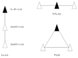
複数台のUAVを使った編隊飛行の例を図19に示す。一般的には、リーダー・フォロワー編隊(leader-follower formation)により飛行する。飛行全体を指導するリーダー役のUAVに対して、フォロワー役のUAVが追従して飛行する。トレイルとはリーダーのUAVを先頭にフォロワーのUAVが縦一列に並んで飛行し、アブレストとはリーダーのUAVを中心にフォロワーのUAVが横一列に並んで飛行する。これに対して、デルタではリーダーのUAVを先頭にフォロワーのUAVが三角形を形成するように追従して飛行する。
FIG. 19 shows an example of formation flight using a plurality of UAVs. In general, it flies in a leader-follower formation. The UAV acting as a follower flies following the UAV acting as a leader instructing the entire flight. The trail flies with the UAV of the leader at the head and the UAVs of the followers line up in a vertical line, and the abrest flies with the UAVs of the followers lined up in a horizontal line around the UAV of the leader. On the other hand, in Delta, the UAV of the leader follows the UAV of the follower so as to form a triangle.
図19の例では、各UAVは進行方向に沿って飛行するため機体の頭(鼻先)は進行方向を向いている。市販のUAVには先頭部分にカメラが取り付けられているものが多く、このカメラを使って前方のシーンを撮像することができる。UAVを使った遠隔パトロールは、先頭部分のカメラで取得した映像を監視することになる。説明の便宜上、全てのUAVは同じ画角のカメラで映像を取得するものとする。例えば、トレイル型編隊飛行では同一方向のカメラ映像を監視するため、リーダーUAVはオクルージョンのない前方映像を取得し、フォロワーUAVは前方のUAVが映り込んだ前方の映像を取得する。この編隊では一列に飛行するため、前方のリーダーUAVが映り込む以外はほぼ重複した時系列画像を取得する。これに対して、アブレスト型編隊飛行では全てのUAVのカメラ映像には他の機体が映り込まず、隣のUAVとの距離によって画面の左右部分が一部重複した時系列画像が得られる。重複箇所を使って画像を合成すれば前方の広視野画像、すなわち前方のパノラマ画像が得られる。また、デルタ型編隊飛行ではリーダーUAVはオクルージョンのない前方映像を取得する。フォロワーUAVの映像はリーダーUAVが映り込むが、隣のUAVとの距離によって画面の左右部分が一部重複した時系列画像が得られる。リーダーUAVが映り込んだ重複箇所を手掛かりに、それらの画像を合成すれば前方のパノラマ画像が得られる。
In the example of FIG. 19, since each UAV flies along the traveling direction, the head (nose) of the aircraft is oriented in the traveling direction. Many commercially available UAVs have a camera attached to the top, and this camera can be used to capture the scene in front. A remote patrol using a UAV monitors a video acquired by a camera at the head. For convenience of explanation, it is assumed that all UAVs acquire images with cameras having the same angle of view. For example, in a trail-type formation flight, to monitor camera images in the same direction, the leader UAV acquires a front image without occlusion, and the follower UAV acquires a front image in which the front UAV is reflected. Since this flight flies in a row, it acquires substantially overlapping time-series images except that the leader UAV ahead is reflected. On the other hand, in the Abrest type formation flight, the other aircraft is not reflected in the camera images of all UAVs, and a time-series image in which the left and right portions of the screen partially overlap depending on the distance to the adjacent UAV is obtained. If images are synthesized using overlapping portions, a wide-field image in front, that is, a panoramic image in front can be obtained. In a Delta formation flight, the leader UAV acquires a forward image without occlusion. The video of the follower UAV is reflected by the leader UAV, but a time-series image in which the right and left portions of the screen partially overlap depending on the distance to the adjacent UAV is obtained. By synthesizing those images based on the overlapped portions reflected by the leader UAV, a panoramic image ahead can be obtained.
図19の編隊飛行では、全てのUAVは進行方向にカメラを向けて飛行するため、編隊飛行の周囲を一度に監視することができない。例えば、左右方向と後方から障害物、人、並びに別のUAVが接近した場合には時系列画像においてそれらの接近を見落すことになる。非特許文献3では図19に示した編隊飛行を制御する方法が公開されているが、あくまで現在地から目的地までの編隊飛行を目的としており、全方位監視などのパトロールを課題とする解決策ではない。
編 In the formation flight shown in FIG. 19, all the UAVs fly with the camera directed in the direction of travel, so that the surroundings of the formation flight cannot be monitored at once. For example, when an obstacle, a person, and another UAV approach from the left and right and from behind, the approach is overlooked in the time-series image. Non-Patent Document 3 discloses a method of controlling the formation flight shown in FIG. 19, but it is intended only for formation flight from the current position to the destination, and there is no solution for patrol such as omnidirectional monitoring. Absent.
本発明は、上記問題点を解決するために成されたものであり、複数台のUAVが編隊を組んで全方位を監視しながら円滑かつ安定的に飛行させるように制御できる飛行制御装置、方法、及びプログラムを提供することを目的とする。
SUMMARY OF THE INVENTION The present invention has been made to solve the above problems, and a flight control device and method capable of controlling a plurality of UAVs to form a formation and fly smoothly and stably while monitoring all directions. , And to provide programs.
上記目的を達成するために、第1の発明に係る飛行制御装置は、複数のUAV(Unmanned Aerial Vehicle)の編隊飛行を制御し、前記編隊飛行を先導するリーダーUAVと前記リーダーUAVに従って編隊を形成する一つ以上のフォロワーUAVを制御する飛行制御装置であって、前記リーダーUAVと前記一つ以上のフォロワーUAVとに付与され、かつ、マーカー間の距離が既知の複数のマーカーの各々の三次元座標を計測する位置計測センサと、前記位置計測センサによって計測された前記リーダーUAVの前記マーカーの各々の三次元座標と、予め設定された前記リーダーUAVの目標地である第1の目標点とに基づいて、前記リーダーUAVの現在位置と、前記第1の目標点までのベクトルと、前記第1の目標点に対する方位角を算出するリーダー位置検出部と、前記リーダーUAVの前記第1の目標点までのベクトルに基づいて、前記リーダーUAVの位置を制御するための第1制御データを更新するリーダー位置制御部と、前記リーダーUAVについて更新された前記第1制御データと、前記リーダーUAVについて算出された前記方位角とに基づいて、前記リーダーUAVにおける、飛行指令データを算出し、算出した前記飛行指令データに基づいて前記リーダーUAVの運動を制御する第1の飛行コマンド変換部と、前記一つ以上のフォロワーUAVについて、前記位置計測センサによって計測された前記フォロワーUAVの前記マーカーの各々の三次元座標と、編隊によって定まる前記フォロワーUAVの第2の目標点とに基づいて、前記フォロワーUAVの現在位置と、前記第2の目標点までのベクトルと、前記第2の目標点に対する方位角とを算出するフォロワー位置検出部と、前記一つ以上のフォロワーUAVについて、前記リーダーUAVの方位角と前記フォロワーUAVの方位角の差と、前記フォロワーUAVによって定まる所定の角度との差分が、予め定められた許容角度を満たすように、前記フォロワーUAVの方位角を更新し、前記フォロワーUAVの前記第2の目標点までのベクトル、及び前記更新した前記方位角に基づいて、前記フォロワーUAVの位置を制御するための第2制御データを更新するフォーメーション制御部と、前記一つ以上のフォロワーUAVについて、前記フォロワーUAVについて更新された前記第2制御データと、前記フォロワーUAVについて前記更新した前記方位角とに基づいて、前記フォロワーUAVにおける、飛行指令データを算出し、算出した前記飛行指令データに基づいて前記フォロワーUAVの運動を制御する第2の飛行コマンド変換部と、を含んで構成されている。
In order to achieve the above object, a flight control device according to a first invention controls a formation flight of a plurality of UAVs (Unmanned Aerial Vehicles) and forms a formation in accordance with the leader UAV leading the formation flight and the leader UAV. A flight control device for controlling one or more followers UAV to perform the three-dimensional operation of each of a plurality of markers provided to the leader UAV and the one or more followers UAV and having a known distance between the markers. A position measuring sensor for measuring coordinates, three-dimensional coordinates of each of the markers of the reader UAV measured by the position measuring sensor, and a first target point which is a preset destination of the reader UAV. Calculating a current position of the leader UAV, a vector to the first target point, and an azimuth angle with respect to the first target point based on the current position of the leader UAV. A reader position detecting unit that performs updating of first control data for controlling a position of the reader UAV based on a vector of the reader UAV up to the first target point; and a reader UAV. The flight command data in the leader UAV is calculated based on the first control data updated for the leader UAV and the azimuth angle calculated for the leader UAV, and the leader UAV is calculated based on the calculated flight command data. A first flight command converter for controlling the movement of the follower, three-dimensional coordinates of each of the markers of the follower UAV measured by the position measurement sensor for the one or more followers UAV, and the follower determined by formation The current UAV of the follower UAV based on the second target point of the UAV. Position, a vector to the second target point, and a follower position detector that calculates an azimuth angle with respect to the second target point; and, for the one or more followers UAV, an azimuth angle of the reader UAV and the azimuth angle. The azimuth of the follower UAV is updated so that the difference between the azimuth of the follower UAV and a predetermined angle determined by the follower UAV satisfies a predetermined allowable angle. A formation control unit that updates second control data for controlling the position of the follower UAV based on the vector up to the target point and the updated azimuth, and for the one or more followers UAV, The second control data updated for the follower UAV; and the second control data updated for the follower UAV. A second flight command converter configured to calculate flight command data in the follower UAV based on the azimuth and control the movement of the follower UAV based on the calculated flight command data. Have been.
第2の発明に係る飛行制御方法は、複数のUAV(Unmanned Aerial Vehicle)の編隊飛行を制御し、前記編隊飛行を先導するリーダーUAVと前記リーダーUAVに従って編隊を形成する一つ以上のフォロワーUAVを制御する飛行制御装置における飛行制御方法であって、位置計測センサが、前記リーダーUAVと前記一つ以上のフォロワーUAVとに付与され、かつ、マーカー間の距離が既知の複数のマーカーの各々の三次元座標を計測するステップと、リーダー位置検出部が、前記位置計測センサによって計測された前記リーダーUAVの前記マーカーの各々の三次元座標と、予め設定された前記リーダーUAVの目標地である第1の目標点とに基づいて、前記リーダーUAVの現在位置と、前記第1の目標点までのベクトルと、前記第1の目標点に対する方位角を算出するステップと、リーダー位置制御部が、前記リーダーUAVの前記第1の目標点までのベクトルに基づいて、前記リーダーUAVの位置を制御するための第1制御データを更新するステップと、第1の飛行コマンド変換部が、前記リーダーUAVについて更新された前記第1制御データと、前記リーダーUAVについて算出された前記方位角とに基づいて、前記リーダーUAVにおける、飛行指令データを算出し、算出した前記飛行指令データに基づいて前記リーダーUAVの運動を制御するステップと、フォロワー位置検出部が、前記一つ以上のフォロワーUAVについて、前記位置計測センサによって計測された前記フォロワーUAVの前記マーカーの各々の三次元座標と、編隊によって定まる前記フォロワーUAVの第2の目標点とに基づいて、前記フォロワーUAVの現在位置と、前記第2の目標点までのベクトルと、前記第2の目標点に対する方位角とを算出するステップと、フォーメーション制御部が、前記一つ以上のフォロワーUAVについて、前記リーダーUAVの方位角と前記フォロワーUAVの方位角の差と、前記フォロワーUAVによって定まる所定の角度との差分が、予め定められた許容角度を満たすように、前記フォロワーUAVの方位角を更新し、前記フォロワーUAVの前記第2の目標点までのベクトル、及び前記更新した前記方位角に基づいて、前記フォロワーUAVの位置を制御するための第2制御データを更新するステップと、第2の飛行コマンド変換部が、前記一つ以上のフォロワーUAVについて、前記フォロワーUAVについて更新した前記第2制御データと、前記フォロワーUAVについて前記更新、又は前記算出された前記方位角とに基づいて、前記フォロワーUAVにおける、飛行指令データを算出し、算出した前記飛行指令データに基づいて前記フォロワーUAVの運動を制御するステップと、を含んで実行することを特徴とする。
A flight control method according to a second invention controls a formation flight of a plurality of UAVs (Unmanned Aerial Vehicles), and includes a leader UAV leading the formation flight and one or more followers UAV forming a formation according to the leader UAV. A flight control method in a flight control device for controlling, wherein a position measurement sensor is provided to the reader UAV and the one or more followers UAV, and a tertiary of each of a plurality of markers whose distance between the markers is known. Measuring the original coordinates, wherein the leader position detector detects the three-dimensional coordinates of each of the markers of the reader UAV measured by the position measurement sensor and a preset first destination of the leader UAV. , The current position of the leader UAV, the vector to the first target point, and the first Calculating the azimuth angle of the reader UAV with respect to the target point, and the reader position control unit outputs first control data for controlling the position of the reader UAV based on a vector of the reader UAV to the first target point. Updating, and the first flight command conversion unit, based on the first control data updated for the leader UAV and the azimuth calculated for the leader UAV, issues a flight command in the leader UAV. Calculating data and controlling the movement of the leader UAV based on the calculated flight command data, wherein the follower position detector detects the follower measured by the position measurement sensor for the one or more followers UAV. The three-dimensional coordinates of each of the markers on the UAV and the format determined by the formation Calculating a current position of the follower UAV, a vector to the second target point, and an azimuth angle with respect to the second target point based on a second target point of the word UAV; The unit determines, for the one or more followers UAV, a difference between an azimuth of the leader UAV and an azimuth of the follower UAV and a difference between a predetermined angle determined by the follower UAV and a predetermined allowable angle. And updating the azimuth angle of the follower UAV to control the position of the follower UAV based on the vector of the follower UAV to the second target point and the updated azimuth angle. Updating control data; and a second flight command converter for the one or more follower UAVs, Calculating the flight command data in the follower UAV based on the second control data updated for the follower UAV and the updated or calculated azimuth angle for the follower UAV, and calculating the calculated flight command data. Controlling the movement of the follower UAV based on the following.
第3の発明に係るプログラムは、コンピュータを、第1の発明に記載の飛行制御装置の各部として機能させるためのプログラムである。
プ ロ グ ラ ム A program according to a third invention is a program for causing a computer to function as each section of the flight control device according to the first invention.
本発明の飛行制御装置、方法、及びプログラムによれば、リーダーUAVの方位角とすべてのフォロワーUAVの方位角とで全周を等分するように制御するため、複数台のUAVが編隊を組んで全方位を監視しながら円滑かつ安定的に飛行させるように制御することができる、という効果が得られる。
According to the flight control device, method, and program of the present invention, a plurality of UAVs form a formation in order to control the azimuth of the leader UAV and the azimuths of all followers UAV so as to divide the entire circumference equally. Thus, it is possible to control to fly smoothly and stably while monitoring all directions.
以下、図面を参照して本発明の実施の形態を詳細に説明する。本発明の実施の形態に係る手法は、互いに衝突しないように各UAVへ3次元位置と方位を示す飛行指令を適切に出すことにより、編隊を組んだままで周囲のカメラ映像を取得し、全方位の監視を可能とする。さらに、ユーザの意図で各UAVを制御することにより、人を取り巻く実環境において、人の単独行動では実現不可能な作業を複数のUAVが支援する、あるいは協調作業することを可能とする。
Hereinafter, embodiments of the present invention will be described in detail with reference to the drawings. The method according to the embodiment of the present invention acquires a surrounding camera image while forming a formation by appropriately issuing a flight command indicating a three-dimensional position and a direction to each UAV so as not to collide with each other. Monitoring. Further, by controlling each UAV according to the user's intention, it is possible for a plurality of UAVs to support or cooperate in a work that cannot be realized by a single action of a person in a real environment surrounding the person.
<本発明の第1の実施の形態に係る飛行制御装置の構成>
本発明の第1の実施の形態に係るクアッドロータ型UAVの飛行制御装置の構成について説明する。本実施の形態は複数台のUAVによる編隊飛行を制御して全方位のカメラ映像を取得する形態であり、リーダーUAVとフォロワーUAVとの2台とする場合を例に説明する。 <Configuration of Flight Control Device According to First Embodiment of the Present Invention>
A configuration of a flight control device for a quad rotor UAV according to the first embodiment of the present invention will be described. The present embodiment is a form in which formation flight by a plurality of UAVs is controlled to acquire an omnidirectional camera image, and an example in which a leader UAV and a follower UAV are used will be described.
図1に示すように、本発明の第1の実施の形態に係る飛行制御装置100は、CPUと、RAMと、後述する飛行制御処理ルーチンを実行するためのプログラムや各種データを記憶したROMと、を含むコンピュータで構成することが出来る。この飛行制御装置100は、機能的には図1に示すように位置計測センサ10と、演算部20と、通信部50とを備えている。この構成において、位置計測センサ10は必ずしも構成要素として接続している必要はなく、処理に必要なデータを取得すればよく、演算部20におけるリーダー位置検出部30、リーダー位置制御部32、第1の飛行コマンド変換部34、第2の飛行コマンド変換部35、フォロワー位置検出部40、フォーメーション制御部42、カメラ映像監視部44、及び映像DB46からそれぞれの矢印へのデータの流れは、ハードディスク、RAID装置、CD-ROMなどの記録媒体を利用する、または、ネットワークを介してリモートなデータ資源を利用する形態でもどちらでも構わない。
As shown in FIG. 1, a flight control device 100 according to a first embodiment of the present invention includes a CPU, a RAM, and a ROM storing a program and various data for executing a flight control processing routine described later. , And can be configured by a computer. The flight control device 100 functionally includes a position measurement sensor 10, a calculation unit 20, and a communication unit 50 as shown in FIG. In this configuration, the position measurement sensor 10 does not necessarily need to be connected as a constituent element, but only needs to acquire data necessary for processing, and the reader position detection unit 30, the leader position control unit 32, the first The flow of data from the flight command conversion unit 34, the second flight command conversion unit 35, the follower position detection unit 40, the formation control unit 42, the camera video monitoring unit 44, and the video DB 46 to the respective arrows is as follows. The recording medium such as an apparatus or a CD-ROM may be used, or a remote data resource may be used via a network.
位置計測センサ10は、各UAVに付与され、かつ、マーカー間の距離が既知の複数のマーカーの各々の三次元座標を計測データとして計測する。一般的に、モーションキャプチャ装置は、所定のマーカーの3次元座標をリアルタイムで高精度に計測できることが知られている。本実施の形態では、位置計測センサ10の例として、モーションキャプチャ装置を利用する。図2に示す状況において、位置計測センサ10はグローバル座標系において3次元座標を計測するようにセットアップされており、各UAVに付与された各マーカーの3次元座標が、ある一定間隔で逐次計測される。目標地は点pで示されており、その座標値は飛行計画に応じて任意に設定する。以降では、2台のUAVによる編隊飛行制御の例を説明するが、3台以上のUAVを利用する場合にも本発明の実施の形態の手法を容易に拡張することができることは言うまでもない。
The position measurement sensor 10 measures, as measurement data, the three-dimensional coordinates of each of a plurality of markers provided to each UAV and having a known distance between the markers. In general, it is known that a motion capture device can measure three-dimensional coordinates of a predetermined marker with high accuracy in real time. In the present embodiment, a motion capture device is used as an example of the position measurement sensor 10. In the situation shown in FIG. 2, the position measurement sensor 10 is set up to measure three-dimensional coordinates in a global coordinate system, and the three-dimensional coordinates of each marker assigned to each UAV are sequentially measured at certain fixed intervals. You. The destination is indicated by a point p, and its coordinate value is arbitrarily set according to the flight plan. Hereinafter, an example of formation flight control using two UAVs will be described. However, it is needless to say that the technique of the embodiment of the present invention can be easily extended even when three or more UAVs are used.
リーダーUAV14には点a、点b、点c、並びに点dの位置にセンシング用のマーカーが取り付けられている。点aと点bとを結ぶ第1線分が点cと点dとを結ぶ第2線分と点eの位置で直交しているとする。点eの位置は、線分が直交する条件を満たせばよく、各線分の中点である必要はない。リーダーUAV14のカメラは、点dから点cの方向の向きに設置されている。フォロワーUAV15#1には点a1、点b1、点c1、及び点d1にセンシング用のマーカーが取り付けられている。点a1と点b1とを結ぶ第1線分が点c1と点d1とを結ぶ第2線分と点e1の位置で直交しているとする。フォロワーUAV15#1のカメラは、点d1から点c1の方向の向きに設置されている。なお、フォロワーUAV15#2が存在する場合には、同様に、フォロワーUAV15#2には点a2、点b2、点c2、並びに点d2の位置にセンシング用のマーカーが取り付けられているものとする。点a2と点b2とを結ぶ第1線分が点c2と点d2とを結ぶ第2線分と点e2の位置で直交しているとする。フォロワーUAV15#2のカメラは、点d2から点c2の方向の向きに設置されている。フォロワーUAV15#1、#2において、点e1と点e2の位置は、線分が直交する条件を満たせばよく、各線分の中点である必要はない。
The reader UAV 14 has sensing markers attached at points a, b, c, and d. It is assumed that the first line segment connecting the points a and b is orthogonal to the second line segment connecting the points c and d at the position of the point e. The position of the point e only needs to satisfy the condition that the line segments are orthogonal to each other, and need not be the midpoint of each line segment. The camera of the leader UAV 14 is installed in the direction from the point d to the point c. Followers UAV15 # 1 have sensing markers attached to points a 1 , b 1 , c 1 , and d 1 . The first line segment connecting the points a 1 and the point b 1 are orthogonal with the position of the second line segment and the point e 1 connecting the point c 1 and the point d 1. Followers UAV 15 # 1 camera is installed from point d 1 in the direction of orientation of the point c 1. In the case where followers UAV 15 # 2 is present are likewise followers UAV 15 # point a 2 to 2, point b 2, point c 2, and markers for sensing is attached to the position of the point d 2 Shall be. The first line segment connecting the points a 2 and the point b 2 are orthogonal with a second position of the line segment and the point e 2 connecting the point c 2 and the point d 2. Followers UAV 15 # 2 camera is installed from point d 2 in the direction of orientation of the point c 2. In follower UAV 15 # 1, # 2, the position of the point e 1 and the point e 2 may satisfy the condition that the line segment is perpendicular, not necessarily the midpoint of each line segment.
演算部20は、位置計測センサ10によりグローバル座標系におけるリーダーUAV14の位置を検出するリーダー位置検出部30と、所定の経路に沿ってリーダーUAV14の飛行を制御するリーダー位置制御部32と、リーダーUAV14に指令データを送出するための第1の飛行コマンド変換部34と、フォロワーUAV15に指令データを送出するための第2の飛行コマンド変換部35と、位置計測センサ10によりグローバル座標系におけるフォロワーUAV15の位置を検出するフォロワー位置検出部40と、リーダーUAV14の位置、及びフォロワーUAV15の方位角に基づいてフォロワーUAV15の飛行を制御するフォーメーション制御部42と、各UAVからカメラにより撮影した映像を取得する命令及び映像を映像DB46に転送する命令を送出するカメラ映像監視部44と、映像DB46とを含んで構成されている。なお各処理部の具体的な処理内容は後述の作用の説明において説明する。
The calculation unit 20 includes a reader position detection unit 30 that detects the position of the reader UAV 14 in the global coordinate system by the position measurement sensor 10, a reader position control unit 32 that controls the flight of the reader UAV 14 along a predetermined route, and a reader UAV 14 The first flight command conversion unit 34 for sending command data to the follower UAV 15, the second flight command conversion unit 35 for sending command data to the follower UAV 15, and the position measurement sensor 10 A follower position detection unit 40 for detecting the position, a formation control unit 42 for controlling the flight of the follower UAV 15 based on the position of the leader UAV 14 and the azimuth of the follower UAV 15, and a command for acquiring an image captured by a camera from each UAV. And pictures A camera video monitoring unit 44 sends an instruction to transfer the image DB 46, is configured to include a video DB 46. The specific processing contents of each processing unit will be described in the following description of the operation.
リーダー位置検出部30は、位置計測センサ10によって計測されたリーダーUAV14のマーカーの点a、点b、点c、及び点dの三次元座標と、予め設定されたUAV14の目標地12の目標点pとに基づいて、リーダーUAV14の現在位置e、現在位置eからの目標点pまでのベクトルT、及び目標点pに対する方位角θを算出する。現在位置eは、マーカーの点a、点bの三次元座標を結ぶ第1線分及び点c、点dを結ぶ第2線分の交点eである。方位角θは、グローバル座標系における目標点pに対するマーカーの点a、点bの三次元座標を結んだ第1線分の方位角である。なお、目標点pが第1の目標点の一例であり、方位角θが第1の目標点に対する方位角の一例である。
The leader position detection unit 30 calculates the three-dimensional coordinates of the points a, b, c, and d of the marker of the reader UAV 14 measured by the position measurement sensor 10 and the preset target point of the destination 12 of the UAV 14. Based on p, a current position e of the leader UAV 14, a vector T from the current position e to the target point p, and an azimuth θ with respect to the target point p are calculated. The current position e is an intersection point e of a first line connecting the three-dimensional coordinates of the points a and b of the marker and a second line connecting the points c and d. The azimuth angle θ is the azimuth angle of the first line connecting the three-dimensional coordinates of the points a and b of the marker with respect to the target point p in the global coordinate system. Note that the target point p is an example of a first target point, and the azimuth θ is an example of an azimuth with respect to the first target point.
リーダー位置制御部32は、リーダーUAV14の目標点pまでのベクトルTから求まる距離||T||に基づいて、リーダーUAV14の位置を制御するための第1制御データuを更新する。また、リーダー位置制御部32は、リーダーUAV14について、目標点pに対する予め定められた許容距離ΔLを満たす場合に、編隊完了通知をカメラ映像監視部44に送信する。
The leader position control unit 32 updates the first control data u for controlling the position of the reader UAV 14 based on the distance || T || obtained from the vector T to the target point p of the reader UAV 14. The leader position control unit 32 transmits a formation completion notification to the camera image monitoring unit 44 when the leader UAV 14 satisfies a predetermined allowable distance ΔL with respect to the target point p.
第1の飛行コマンド変換部34は、リーダーUAV14について、更新された制御データuと、算出された方位角θとに基づいて、リーダーUAV14における、X軸周りの回転速度Vx、Y軸周りの回転速度Vy、Z軸に沿った速度Vz、及びZ軸周りの回転速度Vθを飛行指令データとして算出し、飛行指令データを通信部50を介してリーダーUAV14に送信することで、算出した飛行指令データに基づいてリーダーUAV14の運動を制御する。
The first flight command converter 34 converts the rotation speed V x around the X axis and the rotation speed V around the Y axis of the reader UAV 14 based on the updated control data u and the calculated azimuth angle θ for the reader UAV 14. The rotation speed V y , the speed V z along the Z-axis, and the rotation speed V θ around the Z-axis are calculated as flight command data, and the flight command data is transmitted to the reader UAV 14 via the communication unit 50 to calculate. The movement of the leader UAV 14 is controlled based on the obtained flight command data.
フォロワー位置検出部40は、一つ以上のフォロワーUAV15#iについて、位置計測センサ10によって計測されたフォロワーUAV15#iのマーカーの各々の三次元座標と、編隊によって定まるフォロワーUAV15#iの目標点piとに基づいて、フォロワーUAV15#iについて、フォロワーUAV15#iの現在位置ei、現在位置eiからの目標点piまでのベクトルTi、及び目標点piに対する方位角θiを算出する。現在位置eiは、マーカーの点ai、点biの三次元座標を結ぶ第1線分及び点ci、点diを結ぶ第2線分の交点eiである。方位角θiは、グローバル座標系における目標点piに対するマーカーの点ai、点biの三次元座標を結んだ第1線分の方位角である。なお、目標点piが第2の目標点の一例であり、方位角θiが第2の目標点に対する方位角の一例である。
The follower position detection unit 40 determines, for one or more followers UAV15 # i, the three-dimensional coordinates of each of the markers of the follower UAV15 # i measured by the position measurement sensor 10, and the target point p of the follower UAV15 # i determined by the formation. based on the i, calculated for followers UAV 15 # i, the current position e i followers UAV 15 # i, the vector T i to the target point p i from the current position e i, and the azimuth angle theta i with respect to the target point p i I do. Current position e i is a second line segment intersection e i connecting the first line segment and the point c i, point d i connecting a i, the three-dimensional coordinates of the point b i point markers. The azimuth angle θ i is the azimuth angle of the first line connecting the three-dimensional coordinates of the marker points a i and b i with respect to the target point p i in the global coordinate system. Note that the target point p i is an example of a second target point, and the azimuth θ i is an example of an azimuth with respect to the second target point.
フォーメーション制御部42は、一つ以上のフォロワーUAV15#iについて、フォロワーUAV15#iの位置を制御するための第2制御データuiを更新するが、条件に応じて処理が異なる。リーダーUAV14の方位角とフォロワーUAV15#iの方位角の差と、フォロワーUAV15#iによって定まる所定の角度との差分を算出し、算出した差分が、予め定められたリーダーUAV14に対するフォロワーUAV15#iの角度の許容角度Δθを満たすか否かに応じて、以下のように処理する。
Formation control unit 42, for one or more followers UAV 15 # i, but updates the second control data u i for controlling the position of the follower UAV 15 # i, the process according to the conditions are different. A difference between the difference between the azimuth of the leader UAV14 and the azimuth of the follower UAV15 # i and a predetermined angle determined by the follower UAV15 # i is calculated, and the calculated difference is determined by the follower UAV15 # i with respect to the predetermined leader UAV14. The following processing is performed depending on whether or not the allowable angle Δθ is satisfied.
差分が、許容角度Δθを満たさない場合には、許容角度Δθを満たす角度となるように、フォロワーUAV15#iの方位角θiを更新し、フォロワーUAV15#iの目標点piまでのベクトルTi’、及び更新された方位角θiから求まる距離||Ti’||に基づいて、フォロワーUAV15#iの位置を制御するための第2制御データuiを更新する。差分が、許容角度Δθを満たす場合には、フォロワーUAV15#iの目標点piまでのベクトルTi’、及び算出された方位角θiから求まる距離||Ti’||に基づいて、第2制御データuiを更新する。また、フォーメーション制御部42は、フォロワーUAV15#iについて、目標点piに対する予め定められた許容距離ΔLを満たす場合に、編隊完了通知をカメラ映像監視部44に送信する。このように、フォーメーション制御部42は、リーダーUAV14の方位角とすべてのフォロワーUAV15#iの更新後の方位角(又は算出した方位角)とで全周を等分するように、フォロワーUAV#iの方位角を更新する。
If the difference does not satisfy the allowable angle Δθ, the azimuth θ i of the follower UAV15 # i is updated so that the difference satisfies the allowable angle Δθ, and the vector T to the target point p i of the follower UAV15 # i is updated. i ', and the distance obtained from the updated azimuth θ i || T i' based on ||, and updates the second control data u i for controlling the position of the follower UAV 15 # i. Difference is acceptable if it meets the angle Δθ based on the || 'distance || T i obtained from, and the calculated azimuth angle theta i' the vector T i to the target point p i followers UAV 15 # i, updates the second control data u i. In addition, the formation control unit 42 transmits a formation completion notification to the camera video monitoring unit 44 when the follower UAV 15 # i satisfies a predetermined allowable distance ΔL with respect to the target point p i . In this way, the formation control unit 42 sets the follower UAV # i so that the entire circumference is equally divided by the azimuth of the leader UAV14 and the updated azimuth (or the calculated azimuth) of all the followers UAV15 # i. Update the azimuth of.
第2の飛行コマンド変換部35は、一つ以上のフォロワーUAV15#i(本実施の形態では、i=1のみの場合を例に説明する。)について、後述するフォーメーション制御部42で更新された制御データuiと、更新又は算出された方位角θiとに基づいて、フォロワーUAV15#iにおける、X軸周りの回転速度Vx、Y軸周りの回転速度Vy、Z軸に沿った速度Vz、及びZ軸周りの回転速度Vθを飛行指令データとして算出し、飛行指令データを通信部50を介してフォロワーUAV15#iに送信することで、算出した飛行指令データに基づいてフォロワーUAV15#iの運動を制御する。
The second flight command conversion unit 35 is updated by the formation control unit 42, which will be described later, for one or more follower UAVs 15 # i (in the present embodiment, an example in which only i = 1 is described). Based on the control data u i and the updated or calculated azimuth angle θ i , the follower UAV 15 # i has a rotation speed V x around the X axis, a rotation speed V y around the Y axis, and a speed along the Z axis. V z, and calculates the rotational speed V theta around the Z axis as the flight command data, by sending the flight follower UAV15 command data via the communication unit 50 # i, followers based on the calculated flight command data UAV15 Control the movement of #i.
カメラ映像監視部44は、リーダーUAV14、及び一つ以上のフォロワーUAV15#iの編隊完了通知のすべてを受信した場合に、リーダーUAV14、及び一つ以上のフォロワーUAV15#iのカメラにより映像を取得するように制御する。
When the camera image monitoring unit 44 receives all the formation completion notifications of the leader UAV 14 and one or more followers UAV 15 #i, the camera image monitoring unit 44 acquires images by the cameras of the leader UAV 14 and one or more followers UAV 15 #i. Control.
通信部50は、飛行指令データをリーダーUAV14、及び一つ以上のフォロワーUAV15#iに送信する。また、通信部50は、カメラ映像監視部44からの取得の命令に応じてリーダーUAV14、及び一つ以上のフォロワーUAV15#iにカメラの映像を取得する命令を通知する。また、通信部50は、カメラ映像監視部44からの転送の命令により各UAVについて取得した映像を映像DB46に格納する。映像DB46はオペレータが操作するメインサーバーと接続されている(図示省略)。各UAVから映像DB46への転送は無線を利用して映像を送信する。あるいは各UAV内部のメモリに一時保存しておき、適宜、オペレータの指示または一定間隔をおいて無線経由で映像を送信してもよい。
The communication unit 50 transmits the flight command data to the leader UAV14 and one or more followers UAV15 # i. In addition, the communication unit 50 notifies the leader UAV 14 and one or more followers UAV 15 #i of an instruction to acquire a camera image in response to the acquisition instruction from the camera image monitoring unit 44. In addition, the communication unit 50 stores the video acquired for each UAV according to the transfer instruction from the camera video monitoring unit 44 in the video DB 46. The video DB 46 is connected to a main server operated by an operator (not shown). The transfer from each UAV to the video DB 46 transmits the video using wireless. Alternatively, the video may be temporarily stored in a memory inside each UAV, and the video may be transmitted by radio at an instruction of the operator or at a certain interval as appropriate.
<本発明の第1の実施の形態に係る飛行制御装置の作用>
次に、本発明の第1の実施の形態に係る飛行制御装置100の作用について説明する。 <Operation of Flight Control Apparatus According to First Embodiment of Present Invention>
Next, the operation of theflight control device 100 according to the first embodiment of the present invention will be described.
次に、本発明の第1の実施の形態に係る飛行制御装置100の作用について説明する。 <Operation of Flight Control Apparatus According to First Embodiment of Present Invention>
Next, the operation of the
リーダーUAV14及び一つ以上のフォロワーUAV15の各々の三次元座標の計測を開始すると、飛行制御装置100は、図3に示す飛行制御処理ルーチンを実行する。なお、飛行制御処理ルーチンは、各ステップの詳細において説明するようにステップごとに独立して処理を繰り返しているものとする。
When the measurement of the three-dimensional coordinates of each of the leader UAV 14 and one or more followers UAV 15 is started, the flight control device 100 executes a flight control processing routine shown in FIG. It is assumed that the flight control processing routine repeats the processing independently for each step as described in detail of each step.
まず、ステップS100では、リーダー位置検出部30は、位置計測センサ10によって計測されたリーダーUAV14のマーカーの点a、点b、点c、及び点dの三次元座標と、予め設定されたリーダーUAV14の目標地12の目標点pとに基づいて、マーカーの点a、点bの三次元座標を結ぶ第1線分及び点c、点dを結ぶ第2線分の交点e、交点eからの目標点pまでのベクトルT、及びグローバル座標系における目標点pに対するマーカーの点a、点bの三次元座標を結んだ第1線分の方位角θを算出する。
First, in step S100, the reader position detecting unit 30 determines the three-dimensional coordinates of the points a, b, c, and d of the marker of the reader UAV14 measured by the position measurement sensor 10 and the preset reader UAV14. Of the first line connecting the three-dimensional coordinates of the points a and b of the marker and the second line connecting the points c and d based on the target point p of the destination 12 The vector T to the target point p and the azimuth angle θ of the first line connecting the three-dimensional coordinates of the marker points a and b with respect to the target point p in the global coordinate system are calculated.
次に、ステップS102では、リーダー位置制御部32は、リーダーUAV14の目標点pまでのベクトルTから求まる距離||T||に基づいて、リーダーUAV14の位置を制御するための第1制御データuを更新する。また、リーダー位置制御部32は、所定の条件に応じて、編隊完了通知又は編隊未完了通知をカメラ映像監視部44に送信する。
Next, in step S102, the leader position control unit 32 determines the first control data u for controlling the position of the reader UAV 14 based on the distance || T || To update. Further, the leader position control unit 32 transmits a formation completion notification or a formation non-completion notification to the camera video monitoring unit 44 according to a predetermined condition.
ステップS104では、第1の飛行コマンド変換部34は、リーダーUAV14について、ステップS102で更新された制御データuと、算出された方位角θとに基づいて、リーダーUAV14における、X軸周りの回転速度Vx、Y軸周りの回転速度Vy、Z軸に沿った速度Vz、及びZ軸周りの回転速度Vθを飛行指令データとして算出し、飛行指令データを通信部50を介してリーダーUAV14に送信することで、算出した飛行指令データに基づいてリーダーUAV14の運動を制御する。
In step S104, the first flight command conversion unit 34 calculates the rotation speed of the reader UAV 14 about the X axis in the reader UAV 14 based on the control data u updated in step S102 and the calculated azimuth angle θ. V x, leader via the rotational speed V y, calculates the speed V z along the Z axis, and the rotational speed V theta around the Z axis as the flight command data, the communication unit 50 the flight command data about the Y-axis UAV14 To control the movement of the leader UAV 14 based on the calculated flight command data.
ステップS106では、一つ以上のフォロワーUAV15を順番に制御するため、フォロワーUAV15#i(i=1,2,・・・)を選択する。本実施の形態では、i=1であるため、1台のみ選択される。
In step S106, followers UAV15 # i (i = 1, 2,...) Are selected in order to control one or more followers UAV15 in order. In this embodiment, since i = 1, only one device is selected.
ステップS108では、フォロワー位置検出部40が、位置計測センサ10によって計測されたフォロワーUAV15#iのマーカーの各々の三次元座標と、リーダーUAV14の第1線分及び第2線分の交点eから、リーダーUAV14の第1線分又は第2線分の延長線上に予め定められた距離だけ離れた座標により定まる、フォロワーUAV15#iの目標点piとに基づいて、フォロワーUAV15#iについて、マーカーの点ai、点biの三次元座標を結ぶ第1線分及び点ci、点diを結ぶ第2線分の交点、交点からの目標点piまでのベクトルTi、及びグローバル座標系における目標点piに対するマーカーの点ai、点biの三次元座標を結んだ第1線分の方位角を算出する。
In step S108, the follower position detection unit 40 calculates, from the three-dimensional coordinates of each of the markers of the follower UAV15 # i measured by the position measurement sensor 10, and the intersection e of the first line segment and the second line segment of the leader UAV14. Based on the target point p i of the follower UAV15 # i, which is determined by coordinates at a predetermined distance on an extension of the first or second line segment of the leader UAV14, the marker of the follower UAV15 # i point a i, point b the first line segment and the point c i connecting the three-dimensional coordinates of the i, second line of intersection connecting points d i, the vector T i to the target point p i from the intersection, and the global coordinates The azimuth of the first line segment connecting the three-dimensional coordinates of the marker points a i and b i with respect to the target point p i in the system is calculated.
ステップS110では、フォーメーション制御部42は、フォロワーUAV15#iについて、フォロワーUAV15#iの目標点piまでのベクトルTiから求まる距離||Ti||に基づいて、フォロワーUAV15#iの位置を制御するための第2制御データuiを更新する。また、フォーメーション制御部42は、所定の条件に応じて、編隊完了通知又は編隊未完了通知をカメラ映像監視部44に送信する。
In step S110, formation control unit 42, the follower UAV 15 # i, based on the distance || T i || obtained from the vector T i to the target point p i followers UAV 15 # i, the position of the follower UAV 15 # i updates the second control data u i to control. Further, the formation control unit 42 transmits a formation completion notification or a formation non-completion notification to the camera video monitoring unit 44 according to a predetermined condition.
ステップS112では、第2の飛行コマンド変換部35は、フォロワーUAV15#iについて、ステップS110で更新された第2制御データuiと、算出された方位角θiとに基づいて、フォロワーUAV15#iにおける、X軸周りの回転速度Vx、Y軸周りの回転速度Vy、Z軸に沿った速度Vz、及びZ軸周りの回転速度Vθを飛行指令データとして算出し、飛行指令データを通信部50を介してフォロワーUAV15#iに送信することで、算出した飛行指令データに基づいてフォロワーUAV15#iの運動を制御する。
In step S112, the second flight command conversion unit 35, the follower UAV 15 # i, based on the second control data u i, is calculated and the azimuth angle theta i updated in step S110, followers UAV 15 # i in the rotational speed V x about the X-axis, the rotational speed V y around the Y-axis, the speed V z along the Z axis, and calculates the rotational speed V theta around the Z axis as the flight command data, the flight command data The motion of the follower UAV 15 # i is controlled based on the calculated flight command data by transmitting the data to the follower UAV 15 # i via the communication unit 50.
ステップS114では、全てのフォロワーUAV15#iについて制御を終了したかを判定し、終了していなければステップS106に戻って次のフォロワーUAV15#iを選択して処理を繰り返し、終了していればステップS116へ移行する。
In step S114, it is determined whether the control has been completed for all the followers UAV15 # i, and if not completed, the process returns to step S106 to select the next follower UAV15 # i and repeats the processing. The process moves to S116.
ステップS116では、カメラ映像監視部44は、全てのフォロワーUAV15#iについて編隊完了通知を受信して編隊が完了したかを判定し、完了していれば、リーダーUAV14及び全てのフォロワーUAV15#iからカメラの映像を同期させて取得する命令を通信部50を介して各UAVに送信し、通信部50に取得した映像を映像DB46に転送する命令を送信する。
In step S116, the camera video monitoring unit 44 receives the formation completion notification for all the followers UAV15 # i, determines whether the formation is completed, and if completed, determines from the leader UAV14 and all the followers UAV15 # i. An instruction to synchronize and acquire the image of the camera is transmitted to each UAV via the communication unit 50, and an instruction to transfer the acquired image to the image DB 46 is transmitted to the communication unit 50.
次に、ステップS100のリーダー位置検出部30のリーダー位置検出処理の詳細について説明する。
Next, details of the leader position detection processing of the leader position detection unit 30 in step S100 will be described.
図4はリーダー位置検出部30の処理のフロー図である。リーダー位置検出部30は処理を開始すると、ステップS1000で、グローバル座標系における目標地12の目標点pを設定する。目標点pは操作者が決定した任意の三次元座標でよい。リーダーUAV14が目的地に到達すると、次の目標地12の3次元座標pが与えられる。目標地12の3次元座標pは編隊飛行の経路に沿って離散的に与えられる。
FIG. 4 is a flowchart of the processing of the reader position detection unit 30. Upon starting the process, the leader position detection unit 30 sets a target point p of the destination 12 in the global coordinate system in step S1000. The target point p may be any three-dimensional coordinates determined by the operator. When the leader UAV 14 reaches the destination, three-dimensional coordinates p of the next destination 12 are given. The three-dimensional coordinates p of the destination 12 are discretely given along the formation flight path.
ステップS1002で、リーダーUAV14のマーカーの点a、点b、点c、及び点dを位置計測センサ10により検出し、その交点eの位置を算出する。交差する位置eにセンシング用のマーカーを設置してもよいが、本実施の形態では汎用性のために、点eの位置を4つのマーカーの点a、点b、点c、及び点dから計算で求める。本処理では、点eの3次元座標を現在位置と称しており、以降では、点eをリーダーUAV14の現在位置とする。
In step S1002, the position measuring sensor 10 detects the points a, b, c, and d of the marker of the reader UAV 14, and calculates the position of the intersection e. Although a marker for sensing may be installed at the intersecting position e, in the present embodiment, the point e is moved from the points a, b, c, and d of the four markers for versatility. Obtain by calculation. In this processing, the three-dimensional coordinates of the point e are referred to as the current position, and hereinafter, the point e is set as the current position of the reader UAV14.
ステップS1004で、リーダーUAV14の現在位置(点e)から目標地(点p)までのベクトルTを、T=p-eの計算により求める。
In step S1004, a vector T from the current position (point e) of the reader UAV 14 to the destination (point p) is obtained by calculating T = pe.
ステップS1006で、点aから点bへのベクトルa-bがベクトルTと直交するために必要な回転角θ(方位角)をベクトル内積の関係を利用して算出する。図5は、マーカーの点a、マーカーの点b、及び目標地の点pをZw軸方向から視た位置と方位の関係を表す。方位角θ=0のとき、ベクトルa-bがベクトルTと直交する。
In step S1006, a rotation angle θ (azimuth) required for the vector ab from the point a to the point b to be orthogonal to the vector T is calculated using the relationship between vector inner products. Figure 5 represents the point of the marker a, point markers b, and the relationship between the position and orientation as viewed from the Z w axis point p of the target areas. When the azimuth θ = 0, the vector ab is orthogonal to the vector T.
ステップS1008で、位置検出の処理を停止するかを判定し、処理を停止する場合にはリーダー位置検出部30の処理を終了し、終了しない場合にはステップS1002に戻って処理を繰り返す。なお、処理を停止する場合とは、ここでは操作者がリーダーUAV14の飛行制御を終了する場合とし、以下の処理においても同様である。
In step S1008, it is determined whether or not to stop the position detection process. If the process is to be stopped, the process of the reader position detection unit 30 is ended. If not, the process returns to step S1002 to repeat the process. Here, the case where the processing is stopped is defined as a case where the operator ends the flight control of the leader UAV 14, and the same applies to the following processing.
リーダー位置検出部30では、以上の処理により、リーダーUAVの現在位置(点e)と、目標点pまでのベクトルTと、方位角θとを算出する。
The leader position detection unit 30 calculates the current position (point e) of the leader UAV, the vector T to the target point p, and the azimuth angle θ by the above processing.
次に、ステップS102のリーダー位置制御部32のリーダー位置制御処理の詳細について説明する。本処理では、リーダー位置検出部30で得たベクトルTに基づき、現在位置から目標地までの直線飛行を制御するための処理フローを説明する。
Next, details of the leader position control process of the leader position control unit 32 in step S102 will be described. In this processing, a processing flow for controlling a straight flight from the current position to the destination based on the vector T obtained by the leader position detection unit 30 will be described.
図6はリーダー位置制御部32の処理のフロー図である。リーダー位置制御部32は処理を開始すると、ステップS1100で、許容距離を指定する。許容距離とは、リーダーUAV14の現在位置eが目標地の点pに到達したかどうかを判定するための距離ΔLである。UAVの飛行には空気抵抗によるゆらぎが影響を与えるため、許容距離ΔLの例として10センチメートルとする。
FIG. 6 is a flowchart of the processing of the reader position control unit 32. Upon starting the process, the leader position control unit 32 specifies an allowable distance in step S1100. The allowable distance is a distance ΔL for determining whether the current position e of the reader UAV 14 has reached the point p of the destination. Since the fluctuation of the air resistance affects the flight of the UAV, the allowable distance ΔL is set to 10 cm as an example.
リーダー位置検出部30において、リーダーUAV14の現在位置(点e)が位置計測センサ10を使って時系列に得られており、現在位置を取得するたびに本処理ルーチンのステップS1102に与えられる(図4及び図6にはXと記した)。
In the leader position detection unit 30, the current position (point e) of the reader UAV 14 is obtained in time series using the position measurement sensor 10, and is given to step S1102 of this processing routine every time the current position is acquired (FIG. X in FIG. 4 and FIG. 6).
ステップS1102で、与えられた現在位置のデータにより、現在位置eから目標地の点pまでの距離||T||を算出する。||・||はベクトルのノルム(大きさ)を表す。
In step S1102, the distance || T || from the current position e to the point p of the destination is calculated based on the given data of the current position. || · || represents the norm (magnitude) of the vector.
ステップS1104で、距離||T||が許容距離ΔL以下(||T||≦ΔL)であるか否かを判定する。||T||≦ΔLであればステップS1110へ移行する。||T||≦ΔLでなく、||T||>ΔLであれば運動を制御するためステップS1106へ移行する。
In step S1104, it is determined whether or not the distance || T || is equal to or smaller than the allowable distance ΔL (|| T || ≦ ΔL). If || T || ≦ ΔL, the process proceeds to step S1110. If || T ||> ΔL instead of || T || ≦ ΔL, the flow shifts to step S1106 to control the movement.
ステップS1106で、第1制御データを

の計算により求める。第1制御データuは、第1の飛行コマンド変換部34においてリーダーUAV14への飛行指令として使われる。 In step S1106, the first control data is
Is calculated by the following formula. The first control data u is used by the firstflight command converter 34 as a flight command to the reader UAV14.
の計算により求める。第1制御データuは、第1の飛行コマンド変換部34においてリーダーUAV14への飛行指令として使われる。 In step S1106, the first control data is
Is calculated by the following formula. The first control data u is used by the first
はフィードバック制御におけるゲインパラメータであり、ユーザが状況に応じて設定する。第1制御データuが計算されると、第1の飛行コマンド変換部34に渡される(図6にはYと記した)。
Is a gain parameter in the feedback control, which is set by the user according to the situation. When the first control data u is calculated, it is passed to the first flight command conversion unit 34 (denoted as Y in FIG. 6).
この反復を続けることによりリーダーUAV14は目標地の点pに近づき、||T||≦ΔLを満たすとき、リーダーUAV14が目標地に到達したと判定してホバリング状態になる。
に よ り By continuing this repetition, the leader UAV 14 approaches the point p of the destination, and when || T || ≦ ΔL is satisfied, the leader UAV 14 determines that the leader UAV 14 has reached the destination and enters the hovering state.
ステップS1107で、リーダーUAV14の編隊が未完了であるものとして、カメラ映像監視部44に編隊未完了通知を送信する(図6にはWと記した)。
In step S1107, it is determined that the formation of the leader UAV 14 has not been completed, and a formation completion notification is transmitted to the camera video monitoring unit 44 (denoted by W in FIG. 6).
ステップS1108で、位置制御の処理を停止するかを判定し、処理を停止する場合にはリーダー位置制御部32の処理を終了し、終了しない場合にはステップS1102に戻って処理を繰り返す。
In step S1108, it is determined whether to stop the position control process. If the process is to be stopped, the process of the reader position control unit 32 is ended. If not, the process returns to step S1102 to repeat the process.
ステップS1110で、ホバリング状態でリーダーUAV14を待機させるように制御する。
In step S1110, control is performed such that the reader UAV 14 is put on standby in a hovering state.
ステップS1112で、カメラ映像監視部44に編隊完了通知を送信し(図6にはWと記した)、ステップS1102へ移行する。
In step S1112, a formation completion notification is transmitted to the camera video monitoring unit 44 (denoted by W in FIG. 6), and the flow shifts to step S1102.
以上の処理によって、リーダー位置制御部32は、リーダーUAV14の現在位置eから目標地の点pまでの距離||T||に応じて第1制御データuを出力する。
With the above processing, the leader position control unit 32 outputs the first control data u according to the distance || T || from the current position e of the reader UAV 14 to the point p of the destination.
次に、ステップS104の第1の飛行コマンド変換部34の飛行コマンド変換処理の詳細について説明する。
Next, details of the flight command conversion processing of the first flight command conversion unit 34 in step S104 will be described.
第1の飛行コマンド変換部34の処理により、リーダーUAV14について、リーダー位置制御部32より与えられる制御データuとリーダー位置検出部30で得た方位θを、リーダーUAV14に応じて飛行コマンドの飛行指令データへ変換して通信部50から無線経由で指令する。UAV14への飛行コマンドには様々なデータ形式が存在するが、本実施の形態では、市販製品のAR Drone 2.0を例にした場合を示す。ただし、それ以外のUAV14の飛行を制御する場合にも、本実施の形態を利用できることは言うまでもない。また、以下は第1の飛行コマンド変換部34におけるリーダーUAV14の場合を例に説明するが、第2の飛行コマンド変換部35についても第1の飛行コマンド変換部34と同様に制御できる。第2の飛行コマンド変換部35において、一つ以上のフォロワーUAV15#iを制御する場合については、第1制御データuと方位角θとを、第2制御データuiと方位角θiとに置き換えて飛行指令データに変換して制御する。
By the processing of the first flight command conversion unit 34, the control data u given by the leader position control unit 32 and the azimuth θ obtained by the leader position detection unit 30 are used for the leader UAV 14, and the flight command of the flight command is given according to the leader UAV 14. The data is converted into data and the communication unit 50 issues a command via wireless communication. Although there are various data formats for the flight command to the UAV 14, in the present embodiment, a case is shown in which a commercially available AR Drone 2.0 is used as an example. However, it is needless to say that the present embodiment can be used for controlling the flight of the UAV 14 other than the above. In the following, the case of the leader UAV 14 in the first flight command converter 34 will be described as an example. However, the second flight command converter 35 can be controlled in the same manner as the first flight command converter 34. In the second flight command conversion unit 35, a case of controlling one or more followers UAV 15 # i includes a first control data u and the azimuth angle theta, to the azimuth and theta i second control data u i It is converted to flight command data and controlled.
図7は第1の飛行コマンド変換部34の飛行コマンド変換処理のフロー図である。第1の飛行コマンド変換部34は処理を開始すると、ステップS1200で、更新された制御データuと、算出された方位角θとの入力を受け付ける。
FIG. 7 is a flowchart of the flight command conversion process of the first flight command conversion unit 34. When the first flight command conversion unit 34 starts the process, in step S1200, the input of the updated control data u and the calculated azimuth angle θ is accepted.
ステップS1202で、制御データuと方位角θとの組み合わせを、リーダーUAV14へ送信するための飛行指令データへ変換する。リーダーUAV14への飛行指令データは、機体に設定されたX軸周りの回転速度Vx、Y軸周りの回転速度Vy、Z軸に沿った速度Vzと、Z軸周りの回転速度Vθになる。制御データuがu=(ux,uy,uz)と与えられるとする。UAV14では、X軸周りの回転がY軸の並進運動を生み出し、Y軸周りの回転がX軸の並進運動を生み出すため、本処理では、リーダーUAV14に与える飛行指令データを以下(1)式により変換する。
In step S1202, the combination of the control data u and the azimuth angle θ is converted into flight command data to be transmitted to the reader UAV14. Flight instruction data to the reader UAV14 the rotational speed V x around the X axis is set to the body, the rotational speed V y around the Y axis, and the velocity V z along the Z-axis, the rotational speed V theta around the Z axis become. Control data u is u = (u x, u y , u z) and is given as. In the UAV 14, since the rotation about the X axis produces a translational movement on the Y axis and the rotation about the Y axis produces a translational movement on the X axis, in this processing, the flight command data given to the reader UAV 14 is expressed by the following equation (1). Convert.

・・・(1)
... (1)
係数αx、αy、αz、αθはAR Drone 2.0が扱うことができる変換係数であり、パラメータとしてユーザが決めてよく、例えば、αx=αy=αz=αθ=0.1と与える。
The coefficients α x , α y , α z , and α θ are conversion coefficients that can be handled by the AR Drone 2.0 and may be determined by the user as a parameter. For example, α x = α y = α z = α θ = 0. Give 1
ステップS1204で、通信部50を介して無線通信により(1)式で算出した飛行指令データをUAV14へ送信する。
In step S1204, the flight command data calculated by the formula (1) is transmitted to the UAV 14 by wireless communication via the communication unit 50.
本処理は、リーダー位置制御部32で得た制御データuとリーダー位置検出部30で得た方位角θが与えられるたびに、(1)式で算出した飛行指令データをリーダーUAV14へ送り続ける。図5で示したように、方位角θを送出することにより、目標地の点pに対するリーダーUAV14の向きはマーカーの点aとマーカーの点bが点Aと点Bとに一致するように補正される。
In this process, every time the control data u obtained by the leader position control unit 32 and the azimuth angle θ obtained by the leader position detection unit 30 are given, the flight command data calculated by the equation (1) is continuously sent to the reader UAV14. As shown in FIG. 5, by sending the azimuth angle θ, the direction of the leader UAV 14 with respect to the point p of the destination is corrected such that the points a and b of the marker coincide with the points A and B. Is done.
図8はフォロワー位置検出部40のフォロワー位置検出処理のフロー図である。図8において、フォロワーUAV15#iの位置を検出する。本実施の形態では、フォロワーUAV15が1台であるため、i=1の場合のフォロワー位置検出部40の処理フローを説明する。
FIG. 8 is a flowchart of the follower position detection processing of the follower position detection unit 40. In FIG. 8, the position of the follower UAV15 # i is detected. In the present embodiment, since there is one follower UAV 15, a processing flow of the follower position detection unit 40 when i = 1 will be described.
フォロワー位置検出部40は処理を開始すると、ステップS1300で、フォロワーUAV15#1に対して、2台フォーメーションにおける目標地の3次元座標p1を設定する。点p1はリーダーUAV14の現在位置eから点cと点dを結ぶ第2線分の延長線上に距離L+L1だけ離れた座標値とする。L≠=L1の場合も処理内容は変わらないためL=L1,L>0の長さとする。リーダーUAV14の運動に従ってフォーメーション飛行させるため、p1=e+(-2L,0,0)と与える。
Followers position detection unit 40 starts the process in step S1300, with respect to follower UAV 15 # 1, it sets the three-dimensional coordinates p 1 target locations in two formations. Point p 1 is the coordinate value apart on an extension line of the second line segment connecting the current position e the points c and d by a distance L + L 1 of the leader UAV14. Also processing the contents case of L ≠ = L 1 is the length of L = L 1, L> 0 for no change. To make the formation fly according to the movement of the leader UAV14, p 1 = e + (− 2L, 0,0) is given.
図9に、リーダーUAV14とフォロワーUAV15#1の初期状態での位置関係を示す。初期状態として、フォロワーUAV15#1はリーダーUAV14の方向を向いているが、本処理はリーダーUAV14とフォロワーUAV15#1の初期位置と初期方向に依存しない。
FIG. 9 shows the positional relationship between the leader UAV 14 and the follower UAV 15 # 1 in the initial state. As an initial state, the follower UAV 15 # 1 is facing the direction of the leader UAV 14, but this processing does not depend on the initial position and the initial direction of the leader UAV 14 and the follower UAV 15 # 1.
ステップS1302で、フォロワーUAV15#1に装着したマーカー点a1、点b1、点c1、及び点d1を位置計測センサ10により検出して、交点e1の位置を算出する。点e1の座標はフォロワーUAV15#1の現在位置となる。現在位置e1が算出されると、フォーメーション制御部42に渡される(図8にはZと記した)。
In step S1302, the marker point a 1 is mounted on the follower UAV 15 # 1, point b 1, and detects the points c 1, and a point d 1 by a position measuring sensor 10, calculates a position of an intersection e 1. The coordinates of the point e 1 is the current position of the follower UAV15 # 1. When the current position e 1 is calculated and passed to formation control unit 42 (marked as Z in Figure 8).
次に、ステップS1304で、フォロワーUAV15#1の現在位置(点e1)から目標地(点p1)までのベクトルT1を、T1=p1-e1の計算により求める。
Next, in step S1304, a vector T 1 from the current position (point e 1 ) of the follower UAV 15 # 1 to the destination (point p 1 ) is obtained by calculating T 1 = p 1 −e 1 .
ステップS1306で、点a1から点b1へのベクトルa1-b1がベクトルT1となす回転角θ1(方位角)をベクトル内積の関係を利用して算出する。方位角θ1が算出されると、フォーメーション制御部42に渡される(図8にはZと記した)。
In step S1306, the vector a 1 -b 1 from point a 1 to point b 1 is calculated using the relationship between the rotational angle theta 1 (the azimuth) vector inner product formed by the vector T 1. When the azimuth angle theta 1 is calculated, (marked as Z in FIG. 8) is passed to the formation control unit 42.
ステップS1308で、位置検出の処理を停止するかを判定し、処理を停止する場合にはフォロワー位置検出部40の処理を終了し、終了しない場合にはステップS1302に戻って処理を繰り返す。
In step S1308, it is determined whether or not to stop the position detection process. If the process is to be stopped, the process of the follower position detection unit 40 is ended. If not, the process returns to step S1302 to repeat the process.
以上の処理により、フォロワー位置検出部40ではフォロワーUAV15#1の現在位置(点e1)と、フォロワーUAV15#1の現在位置(点e1)から目標地(点p1)までのベクトルT1と、フォロワーUAV15#1の方位角θ1を算出する。方位角θ1が算出されると、フォーメーション制御部42に渡される(図8にはZと記した)。
By the above processing, the current position of the follower position detecting unit 40 in the follower UAV 15 # 1 (point e 1), the vector T 1 of the current position of the follower UAV 15 # 1 (point e 1) to the target locations (points p 1) And the azimuth θ1 of the follower UAV15 # 1 is calculated. When the azimuth angle theta 1 is calculated, (marked as Z in FIG. 8) is passed to the formation control unit 42.
図10はフォーメーション制御部42のフォーメーション制御処理のフロー図である。本実施の形態では、フォロワーUAV15が1台であるため、i=1の場合のフォロワー位置検出部40の処理フローを説明する。図11に示すように、リーダーUAV14の正反対の位置及び向きのフォーメーションでフォロワーUAV15#1を飛行させるように運動を制御する。図11において、点gはリーダーUAV14の位置eとフォロワーUAV15#1の位置e1の中点の座標であり、フォロワーUAV15#1は点gを中心に180度回転した方向を向いた姿勢でリーダーUAV14と同じ方向を飛行する。
FIG. 10 is a flowchart of the formation control process of the formation control unit 42. In the present embodiment, since there is one follower UAV 15, a processing flow of the follower position detection unit 40 when i = 1 will be described. As shown in FIG. 11, the movement is controlled so that the follower UAV 15 # 1 flies in the formation of the position and the direction of the leader UAV 14 opposite to the leader UAV 14. In FIG. 11, point g is the coordinates of the middle point of the position e of the leader UAV14 and the position e1 of the follower UAV15 # 1, and the follower UAV15 # 1 is oriented in a direction rotated by 180 degrees about the point g. Fly in the same direction as.
フォーメーション制御部42は処理を開始すると、ステップS1400で、許容距離ΔLを指定する。許容距離ΔLとは、フォロワーUAV15#iの現在位置e1が目標地の点p1に到達したかどうかを判定するための距離である。便宜上、リーダー位置制御部32で設定した同じ許容距離を設定する。
Upon starting the process, the formation control unit 42 specifies an allowable distance ΔL in step S1400. The allowable distance ΔL is the distance for the current position e 1 follower UAV 15 # i to determine whether the reached point p 1 of the objective point. For convenience, the same allowable distance set by the reader position control unit 32 is set.
フォロワー位置検出部40において、フォロワーUAV15#1の現在位置(点e1)と方位角θ1が位置計測センサ10を使って時系列に得られており、現在位置と方位角θ1を取得するたびにステップS1402に与えられる(図10にはZと記した)。
In the follower position detection unit 40, the current position (point e 1 ) and the azimuth θ 1 of the follower UAV 15 # 1 are obtained in time series using the position measurement sensor 10, and the current position and the azimuth angle θ 1 are obtained. Each time is given to step S1402 (denoted by Z in FIG. 10).
ステップS1402で、与えられた現在位置と方位角θ1のデータから、フォロワーUAV15#1の現在位置e1から目標地の点p1までの距離||Ti||を算出する。
In step S1402, from the given current position and azimuth angle theta 1 of the data to calculate the distance || T i || from the current position e 1 follower UAV 15 # 1 to the point p 1 of the objective point.
ステップS1404で、距離||T1||が許容距離ΔL以下であるか否かを判定する。||T1||≦ΔLであればステップS1418へ移行する。||T1||≦ΔLでなく、||T||>ΔLであれば運動を制御するためステップS1406へ移行する。
In step S1404, it is determined whether or not the distance || T 1 || is equal to or smaller than the allowable distance ΔL. If || T 1 || ≦ ΔL, the flow shifts to step S1418. If || T 1 || ≦ ΔL and not || T ||> ΔL, the process moves to step S1406 to control the movement.
ステップS1406で、フォロワーUAV15#1とリーダーUAV14との方位角の差ω1を以下(2)式により算出する。
In step S1406, is calculated by the difference between omega 1 azimuth followers UAV 15 # 1 and reader UAV14 following equation (2).
・・・(2)
... (2)
ステップS1408で、方位角の差分ω1の絶対値||ω1||が許容角度Δθ以下であるか否かを判定する。許容角度Δθ以下であればステップS1410へ移行する。許容角度Δθ以下でなければステップS1412へ移行する。ここでは、方位誤差の許容値としてΔθを設定するが、ドリフトを考慮して、例えば、Δθ=π/180(ラジアン)と与える。許容角度Δθ以下ならば、フォロワーUAV15#1の方位角はほぼθ1=θ+πとなる。
In step S1408, it is determined whether the absolute value || ω 1 || of the azimuth angle difference ω 1 is equal to or smaller than the allowable angle Δθ. If it is equal to or smaller than the allowable angle Δθ, the flow shifts to step S1410. If it is not equal to or smaller than the allowable angle Δθ, the flow shifts to step S1412. Here, Δθ is set as an allowable value of the azimuth error, but in consideration of drift, for example, Δθ = π / 180 (radian) is given. If the angle is equal to or smaller than the allowable angle Δθ, the azimuth of the follower UAV15 # 1 will be substantially θ 1 = θ + π.
ステップS1410で、フォロワーUAV15#1とリーダーUAV14との方位が真反対の180度をなすようにフォロワーUAV15#1の方位角θ1を以下(3)式により更新する(正の回転を反時計周りの回転とする)。更新した方位角θ1は第2の飛行コマンド変換部35に渡される(図10にはYと記した)。(3)式において、本実施の形態ではi=1である。
In step S1410, follower UAV 15 # 1 and the azimuth angle theta 1 follower UAV 15 # 1 as orientation leader UAV14 forms the true opposite 180 degrees or less (3) counterclockwise rotation of updating (positive by formula Rotation). The azimuth angle theta 1 which was updated and passed to the second flight command conversion unit 35 (in FIG. 10 marked with Y). In the equation (3), i = 1 in the present embodiment.

・・・(3)
... (3)
ステップS1412で、変化がある現在の方位角θ1に応じて、フォロワーUAV15#1の並進ベクトルT1’を以下(4)式により変換する。(4)式において、本実施の形態ではi=1である。ステップS1410を処理した場合には、ステップS1410で更新した方位角θ1を用いる。ステップS1410を処理していない場合には、上記ステップS1306で算出した方位角θ1を用いる。
In step S1412, the translation vector T 1 ′ of the follower UAV 15 # 1 is converted by the following equation (4) according to the current azimuth angle θ 1 at which there is a change. In the equation (4), i = 1 in the present embodiment. With by Step S1410, using the azimuth angle theta 1 updated in step S1410. If not processing step S1410, using the azimuth angle theta 1 calculated at step S1306.

・・・(4)
... (4)
ステップS1414で、第2制御データを

の計算により求める。第2制御データu1は、第2の飛行コマンド変換部35においてフォロワーUAV15#1への飛行指令として使われる。 In step S1414, the second control data
Is calculated by the following formula. Second control data u 1 is used in the second flightcommand conversion unit 35 as flight instruction to followers UAV 15 # 1.
の計算により求める。第2制御データu1は、第2の飛行コマンド変換部35においてフォロワーUAV15#1への飛行指令として使われる。 In step S1414, the second control data
Is calculated by the following formula. Second control data u 1 is used in the second flight
はフィードバック制御におけるゲインパラメータであり、ユーザが状況に応じて設定する。第2制御データu1が計算されると、第2の飛行コマンド変換部35に渡される(図10にはYと記した)。
Is a gain parameter in the feedback control, which is set by the user according to the situation. When the second control data u 1 is computed and passed to the second flight command conversion unit 35 (marked as Y in Fig. 10).
ステップS1415で、フォロワーUAV15#1の編隊が未完了であるものとして、カメラ映像監視部44に編隊未完了通知を送信する(図10にはWと記した)。
In step S1415, a formation incomplete notification is transmitted to the camera video monitoring unit 44 assuming that the formation of the follower UAV15 # 1 has not been completed (denoted by W in FIG. 10).
ステップS1416で、フォーメーション制御の処理を停止するかを判定し、処理を停止する場合にはフォーメーション制御部42の処理を終了し、終了しない場合にはステップS1402に戻って処理を繰り返す。
In step S1416, it is determined whether to stop the formation control process. If the process is to be stopped, the process of the formation control unit 42 is ended. If not, the process returns to step S1402 to repeat the process.
この反復を続けることによりフォロワーUAV15#1は目標地の点p1に近づくことになり、||T1’||≦ΔLを満たすとき図11のフォーメーションに従って飛行する。
Followers UAV 15 # 1 by continuing the iterations will be closer to the point p 1 of the objective point, to fly according formation 11 when satisfying || T 1 '|| ≦ ΔL.
以上の処理によって、フォーメーション制御部42は、フォロワーUAV15#1の現在位置e1から目標地の点p1までの距離||T1’||に応じて制御データuiを出力する。
By the above process, the formation control unit 42 outputs the control data u i corresponding to the distance || T 1 '|| from the current position e 1 follower UAV 15 # 1 to the point p 1 of the objective point.
ステップS1418で、ホバリング状態でフォロワーUAV15#1を待機させるように制御する。
In step S1418, control is performed so that the follower UAV 15 # 1 waits in the hovering state.
ステップS1420で、カメラ映像監視部44に編隊完了通知を送信し(図10にはWと記した)、ステップS1402へ移行する。
In step S1420, a formation completion notification is transmitted to the camera image monitoring unit 44 (denoted by W in FIG. 10), and the flow shifts to step S1402.
図12はカメラ映像監視部44のカメラ映像監視処理のフロー図である。カメラ映像監視部44は、リーダーUAV14とフォロワーUAV15#1による編隊を組んで飛行している間にカメラ映像を取得して全周囲の環境を監視する機能を有する。本実施の形態では、フォロワーUAV15が1台であるため、i=1の場合のカメラ映像監視部44の処理フローを説明する。なお、N台の場合もi=1,2,・・・,Nとして同様に処理できる。
FIG. 12 is a flowchart of the camera video monitoring process of the camera video monitoring unit 44. The camera video monitoring unit 44 has a function of acquiring a camera video and monitoring the entire environment while flying in a formation by the leader UAV14 and the follower UAV15 # 1. In the present embodiment, since there is one follower UAV 15, a processing flow of the camera video monitoring unit 44 when i = 1 will be described. .., N can be processed similarly.
カメラ映像監視部44は、処理を開始すると、ステップS1500で、リーダーUAV14からの編隊通知情報を受信する。編隊通知情報とは、リーダーUAV14とフォロワーUAV15#1による編隊が完了して飛行しているか否かを知らせる通知である。編隊が完了している場合には、編隊通知情報として編隊完了通知を受信する。編隊が完了してない場合や編隊が崩れた場合には、編隊通知情報として編隊未完通知を受信する。
When the process starts, the camera video monitoring unit 44 receives formation notification information from the leader UAV 14 in step S1500. The formation notification information is a notification that informs whether or not the formation by the leader UAV14 and the follower UAV15 # 1 has been completed and is flying. When the formation is completed, a formation completion notification is received as formation notification information. If the formation has not been completed or the formation has collapsed, a formation incomplete notification is received as formation notification information.
ステップS1502で、全てのUAVから編隊完了通知を受信したかを判定し、受信していればステップS1504へ移行し、受信していなければステップS1510へ移行して待機状態に移行する。このように、もし、1台でも編隊が完了していない場合は待機状態になり、まだ通知を受信していないUAVの編隊完了通知を待つ。
In step S1502, it is determined whether or not formation completion notifications have been received from all UAVs. If it has been received, the process proceeds to step S1504, and if not received, the process proceeds to step S1510 to enter a standby state. As described above, if the formation is not completed even for one of the units, the system enters a standby state, and waits for a UAV formation completion notification that has not been received.
ステップS1504で、リーダーUAV14とフォロワーUAV15#1から同期信号を受信する。同期信号は時間:分:秒:フレームから構成されるタイムコードを利用する。タイムコードを取得した映像フレームと合わせることで、リーダーUAV14とフォロワーUAV15#1で取得した映像フレームの同期を合わせることができる。
In step S1504, a synchronization signal is received from the leader UAV14 and the follower UAV15 # 1. The synchronization signal uses a time code composed of hours: minutes: seconds: frames. By combining the time code with the acquired video frame, the synchronization of the video frame acquired by the leader UAV 14 and the follower UAV 15 # 1 can be synchronized.
ステップS1506で、同期信号を受信しながら、UAVの前方のカメラから映像を取得する命令をリーダーUAV14とフォロワーUAV15#1に送信する。通信部50に、リーダーUAV14とフォロワーUAV15#1から取得した映像を転送する命令を送信し、取得した映像DB46に格納する。
In step S1506, a command to acquire a video from a camera in front of the UAV is transmitted to the leader UAV14 and the follower UAV15 # 1 while receiving the synchronization signal. A command to transfer the video obtained from the leader UAV14 and the follower UAV15 # 1 is transmitted to the communication unit 50, and stored in the obtained video DB46.
ステップS1508で、カメラ映像監視の処理を停止するかを判定し、処理を停止する場合にはカメラ映像監視部44の処理を終了し、終了しない場合にはステップS1510に移行して、待機状態となってから処理を繰り返す。
In step S1508, it is determined whether to stop the camera video monitoring process. If the process is to be stopped, the process of the camera video monitoring unit 44 is ended. Then repeat the process.
もし、カメラから映像を取得中に、何らかのトラブルにより編隊が崩れた場合、編隊通知情報において編隊が未完という通知が入る。このとき、カメラ映像の取得を停止させて、編隊が完了するまで待機する。
編 If the formation collapses due to some trouble while acquiring images from the camera, a notification that the formation is incomplete is entered in the formation notification information. At this time, acquisition of camera images is stopped, and the process waits until the formation is completed.
以上の処理によって、カメラ映像監視部44はリーダーUAV14とフォロワーUAV15#1による編隊飛行中に全周囲の映像を取得する。
に よ っ て Through the above processing, the camera image monitoring unit 44 acquires images of the entire surroundings during the formation flight by the leader UAV14 and the follower UAV15 # 1.
以上により、本実施の形態は、位置計測センサ10によってリーダーUAV14とフォロワーUAV15#1の位置と方位を算出し、2台のUAVが編隊を組んで飛行し、全周囲の映像を監視することができる。さらに、リーダーUAV14の目標地の位置pを空間経路に沿って間隔を空けて空間中に設定することで、その軌跡に沿って2台のUAVにより全周囲の映像を監視することができる。
As described above, according to the present embodiment, the position and orientation of the leader UAV14 and the follower UAV15 # 1 are calculated by the position measurement sensor 10, and the two UAVs fly in a formation and monitor images of the entire surroundings. it can. Further, by setting the position p of the destination of the leader UAV 14 in the space at intervals along the spatial route, the images of the entire surroundings can be monitored by the two UAVs along the trajectory.
以上説明したように、第1の実施の形態に係る飛行制御装置によれば、複数台のUAVが編隊を組んで全方位の監視しながら円滑かつ安定的に飛行させるように制御できる。
As described above, according to the flight control device of the first embodiment, it is possible to control a plurality of UAVs to form a formation and to fly smoothly and stably while monitoring all directions.
<本発明の第2の実施の形態に係る飛行制御装置の構成及び作用>
本発明の第2の実施の形態は、上記図1の第1の実施の形態の構成により、リーダーUAV14と2台のフォロワーUAV15が三角形フォーメーションのリーダー・フォロワー編隊飛行をする制御の実施の形態である。本実施の形態では、正三角形のフォーメーションにした場合を例に説明するが、二等辺三角形、辺の長さが全て異なる三角形にも応用できる。本実施の形態では、正三角形のフォーメーションに応じてフォロワーUAV15の飛行を制御する処理が第1の実施の形態と異なるため、以降では第1の実施の形態との差分のみを説明する。 <Configuration and Operation of Flight Control Device According to Second Embodiment of the Present Invention>
The second embodiment of the present invention is an embodiment of the control in which theleader UAV 14 and the two followers UAV 15 perform a leader-follower formation flight in a triangle formation by the configuration of the first embodiment of FIG. is there. In the present embodiment, a case where the formation is an equilateral triangle will be described as an example, but the present invention can also be applied to an isosceles triangle and a triangle whose sides are all different in length. In the present embodiment, the process of controlling the flight of the follower UAV 15 according to the formation of an equilateral triangle is different from that of the first embodiment, and hence only the differences from the first embodiment will be described below.
本発明の第2の実施の形態は、上記図1の第1の実施の形態の構成により、リーダーUAV14と2台のフォロワーUAV15が三角形フォーメーションのリーダー・フォロワー編隊飛行をする制御の実施の形態である。本実施の形態では、正三角形のフォーメーションにした場合を例に説明するが、二等辺三角形、辺の長さが全て異なる三角形にも応用できる。本実施の形態では、正三角形のフォーメーションに応じてフォロワーUAV15の飛行を制御する処理が第1の実施の形態と異なるため、以降では第1の実施の形態との差分のみを説明する。 <Configuration and Operation of Flight Control Device According to Second Embodiment of the Present Invention>
The second embodiment of the present invention is an embodiment of the control in which the
本実施の形態のフォロワー位置検出部40は図8のフローに従う。図8において、i=1の場合がフォロワーUAV15#1に関するフォロワー位置検出部40の処理フローであり、i=2の場合がフォロワーUAV15#2に関するフォロワー位置検出部40の処理フローである。
フ ォ ロ ワ ー The follower position detection unit 40 of the present embodiment follows the flow of FIG. In FIG. 8, the case of i = 1 is the processing flow of the follower position detection unit 40 for the follower UAV 15 # 1, and the case of i = 2 is the processing flow of the follower position detection unit 40 for the follower UAV 15 # 2.
フォロワー位置検出部40は処理を開始すると、ステップS1300で、フォロワーUAV15#iに対して、3台フォーメーションにおける目標地の3次元座標piを設定する。リーダーUAV14の現在位置と点piは正三角形の頂点であり、三角形の重心から各頂点までの距離をLとする。重心gを原点として、リーダーUAV14の現在位置がeであるとき、フォロワーUAV15#1の目標地は3次元座標p1=e+(-2L/3,√3L/2,0)と与え、フォロワーUAV15#2の目標地は3次元座標p2=e+(-2L/3,-√3L/2,0)と与える。
Followers position detection unit 40 starts the process in step S1300, with respect to follower UAV 15 # i, sets the three-dimensional coordinates p i of the target locations, in three formations. Current position and the point p i of the leader UAV14 is a vertex of an equilateral triangle, the distance from the center of gravity of the triangle to each vertex and L. When the current position of the leader UAV 14 is e with the center of gravity g as the origin, the destination of the follower UAV 15 # 1 is given as three-dimensional coordinates p 1 = e + (− 2L / 3, √3L / 2, 0), and the follower UAV 15 The destination of # 2 is given as three-dimensional coordinates p 2 = e + (− 2L / 3, −√3L / 2,0).
図13に、リーダーUAV14とフォロワーUAV15#iの初期状態での位置関係を示す。初期状態として、フォロワーUAV15#iはリーダーUAV14の方向を向いているが、本処理はリーダーUAV14とフォロワーUAV15#iの初期位置と初期方向に依存しない。
FIG. 13 shows the positional relationship between the leader UAV 14 and the follower UAV 15 # i in the initial state. As an initial state, the follower UAV15 # i faces the direction of the leader UAV14, but this processing does not depend on the initial position and the initial direction of the leader UAV14 and the follower UAV15 # i.
ステップS1302で、フォロワーUAV15#iに装着したマーカー点ai、点bi、点ci、及び点diを位置計測センサ10により検出して、交点eiの位置を算出する。点eiの座標はフォロワーUAV15#iの現在位置となる。
In step S1302, the marker points attached to followers UAV 15 # i a i, detects a point b i, point c i, and the point d i by a position measuring sensor 10, calculates a position of an intersection e i. Coordinates of the point e i is the current position of the follower UAV15 # i.
次に、ステップS1304で、フォロワーUAV15#iの現在位置(点ei)から目標地(点pi)までのベクトルTiを、Ti=pi-eiの計算により求める。
Next, in step S1304, a vector T i from the current position (point e i ) of the follower UAV 15 # i to the destination (point p i ) is obtained by calculation of T i = p i -e i .
ステップS1306で、点aiから点biへのベクトルai-biがベクトルTiとなす回転角θi(方位角)をベクトル内積の関係を利用して算出する。
In step S1306, the vector a i -b i from point a i to point b i is calculated vector T i and forms rotation angle theta i (the azimuth angle) by using the relationship between the vector dot product.
以上の処理により、フォロワー位置検出部40ではフォロワーUAV15#iの現在位置(点ei)と、フォロワーUAV15#iの現在位置(点ei)から目標地(点pi)までのベクトルTiと、フォロワーUAV15#iの方位角θiを算出する。
By the above processing, the current position of the follower position detecting unit 40 in the follower UAV 15 # i (point e i), the vector T i of the current position of the follower UAV 15 # i from (point e i) to the target locations (points p i) And the azimuth θ i of the follower UAV15 # i.
本実施の形態のフォーメーション制御部42は図10のフローに従う。図10において、i=1の場合がフォロワーUAV15#1に関するフォーメーション制御部42の処理フローであり、i=2の場合がフォロワーUAV15#2に関するフォーメーション制御部42の処理フローである。
フ ォ ー The formation control unit 42 of the present embodiment follows the flow of FIG. In FIG. 10, the case of i = 1 is the processing flow of the formation control unit 42 regarding the follower UAV15 # 1, and the case of i = 2 is the processing flow of the formation control unit 42 regarding the follower UAV15 # 2.
本実施の形態では、リーダーUAV14の方位から反時計周りに120度回転した方位をフォロワーUAV15#1の方位とし、リーダーUAV14の方位から反時計周りに240度回転した方位をフォロワーUAV15#2の方位とする。このように、リーダーUAV14の方位に対して等分に振り分けた角度の方位を設定する。ステップS1406で、フォロワーUAV15#iとリーダーUAV14との方位角の差分ωiを以下(5)式により算出する。
In the present embodiment, the azimuth rotated 120 degrees counterclockwise from the azimuth of the leader UAV14 is defined as the azimuth of the follower UAV15 # 1, and the azimuth rotated 240 degrees counterclockwise from the azimuth of the leader UAV14 is defined as the azimuth of the follower UAV15 # 2. And In this way, an azimuth of an angle equally divided with respect to the azimuth of the leader UAV 14 is set. In step S1406, it is calculated by the difference between ω i of the azimuth angle of the followers UAV15 # i and the leader UAV14 following equation (5).
・・・(5)
... (5)
ステップS1408で、方位角の差分ωiの絶対値||ωi||が許容角度Δθ以下であるか否かを判定する。許容角度Δθ以下であればステップS1410へ移行する。許容角度Δθ以下でなければステップS1412へ移行する。
In step S1408, it is determined whether the absolute value || ω i || of the azimuth difference ω i is equal to or smaller than the allowable angle Δθ. If it is equal to or smaller than the allowable angle Δθ, the flow shifts to step S1410. If it is not equal to or smaller than the allowable angle Δθ, the flow shifts to step S1412.
ステップS1410で、フォロワーUAV15#iの方位角θiを上記(3)式により更新する。更新した方位角θiは第2の飛行コマンド変換部35に渡される(図10にはYと記した)。
In step S1410, the azimuth θ i of the follower UAV15 # i is updated by the above equation (3). The updated azimuth θ i is passed to the second flight command converter 35 (denoted as Y in FIG. 10).
ステップS1412で、変化がある現在の方位角θiに応じて、フォロワーUAV15#iの並進ベクトルT1’を上記(4)式により変換する。ステップS1410を処理した場合には、ステップS1410で更新した方位角θiを用いる。ステップS1410を処理していない場合には、上記ステップS1306で算出した方位角θiを用いる。
In step S1412, the translation vector T 1 ′ of the follower UAV15 # i is converted by the above equation (4) according to the current azimuth angle θ i having a change. With by step S1410 uses the azimuth angle theta i updated in step S1410. If step S1410 has not been processed, the azimuth θ i calculated in step S1306 is used.
ステップS1414で、第2制御データを

の計算により求める。第2制御データuiは、第2の飛行コマンド変換部35においてフォロワーUAV15#iへの飛行指令として使われる。この反復を続けることによりフォロワーUAV15#iは目的地の点piに近づくことになり、||Ti’||≦ΔLを満たすとき図14のフォーメーションに従って編隊飛行する。 In step S1414, the second control data
Is calculated by the following formula. The second control data u i, used in the second flightcommand conversion unit 35 as flight instruction to followers UAV 15 # i. By continuing this repetition, the follower UAV15 # i approaches the destination point p i, and flies in formation according to the formation of FIG. 14 when || T i '|| ≦ ΔL is satisfied.
の計算により求める。第2制御データuiは、第2の飛行コマンド変換部35においてフォロワーUAV15#iへの飛行指令として使われる。この反復を続けることによりフォロワーUAV15#iは目的地の点piに近づくことになり、||Ti’||≦ΔLを満たすとき図14のフォーメーションに従って編隊飛行する。 In step S1414, the second control data
Is calculated by the following formula. The second control data u i, used in the second flight
以上により、本実施の形態は、位置計測センサ10によってリーダーUAV14とフォロワーUAV15#iの位置と方位を算出し、3台のUAVが編隊を組んで飛行し、全周囲の映像を監視することができる。さらに、リーダーUAV14の目標地の位置pを空間経路に沿って間隔を空けて空間中に設定することで、その軌跡に沿って3台のUAVにより全周囲の映像を監視することができる。
As described above, according to the present embodiment, the position and orientation of the leader UAV 14 and the follower UAV 15 #i are calculated by the position measurement sensor 10, and three UAVs fly in a formation and monitor images of the entire surroundings. it can. Further, by setting the position p of the destination of the leader UAV 14 in the space at intervals along the spatial route, the images of the entire surroundings can be monitored by three UAVs along the trajectory.
<本発明の第3の実施の形態に係る飛行制御装置の構成及び作用>
<Configuration and Operation of Flight Control Device According to Third Embodiment of Present Invention>
本発明の第3の実施の形態は、上記図1の第1の実施の形態の構成により、リーダーUAV14と3台のフォロワーUAV15が正方形フォーメーションのリーダー・フォロワー編隊飛行をする制御の実施の形態である。本実施の形態では、正方形のフォーメーションにした場合を例に説明するが、長方形、菱形、四角形にも応用できる。本実施の形態では、正方形のフォーメーションに応じてフォロワーUAV15の飛行を制御する処理が第2の実施の形態と異なるため、以降では第2の実施の形態との差分のみを説明する。
The third embodiment of the present invention is an embodiment of the control in which the leader UAV 14 and the three followers UAV 15 make a leader-follower formation flight in a square formation by the configuration of the first embodiment of FIG. is there. In this embodiment, a case where the formation is a square will be described as an example, but the present invention can be applied to a rectangle, a rhombus, and a square. In the present embodiment, since the process of controlling the flight of the follower UAV 15 according to the square formation is different from that of the second embodiment, only the differences from the second embodiment will be described below.
本実施の形態のフォロワー位置検出部40は図8のフローに従う。図8において、i=1の場合がフォロワーUAV15#1に関するフォロワー位置検出部40の処理フローであり、i=2の場合がフォロワーUAV15#2に関するフォロワー位置検出部40の処理フローであり、i=3の場合がフォロワーUAV15#3に関するフォロワー位置検出部40の処理フローである。
フ ォ ロ ワ ー The follower position detection unit 40 of the present embodiment follows the flow of FIG. In FIG. 8, the case of i = 1 is the processing flow of the follower position detecting unit 40 for the follower UAV15 # 1, the case of i = 2 is the processing flow of the follower position detecting unit 40 for the follower UAV15 # 2, and i = The case of No. 3 is a processing flow of the follower position detection unit 40 regarding the follower UAV 15 # 3.
フォロワー位置検出部40は処理を開始すると、ステップS1300で、フォロワーUAV15#iに対して、3台フォーメーションにおける目標地の3次元座標piを設定する。リーダーUAV14の現在位置と点piは正方形の頂点であり、正方形の重心から各頂点までの距離をLとする。重心gを原点として、リーダーUAV14の現在位置がeであるとき、フォロワーUAV15#1の目標地は3次元座標p1=e+(-L,L,0)と与え、フォロワーUAV15#2の目標地は3次元座標p2=e+(-2L,0,0)と与え、フォロワーUAV15#3の目標地は3次元座標p3=e+(-L,-L,0)と与える。
Followers position detection unit 40 starts the process in step S1300, with respect to follower UAV 15 # i, sets the three-dimensional coordinates p i of the target locations, in three formations. Current position and the point p i leader UAV14 are vertices of a square, the distance from the square center of gravity to each vertex and L. The center of gravity g as the origin, when the current position of the leader UAV14 is e, the target locations followers UAV 15 # 1 is 3-dimensional coordinates p 1 = e + (- L , L, 0) and given, followers UAV 15 # 2 target locations Is given as three-dimensional coordinates p 2 = e + (− 2L, 0, 0), and the destination of the follower UAV15 # 3 is given as three-dimensional coordinates p 3 = e + (− L, −L, 0).
図15に、リーダーUAV14とフォロワーUAV15#iの初期状態での位置関係を示す。初期状態として、フォロワーUAV15#iはリーダーUAV14の方向を向いているが、本処理はリーダーUAV14とフォロワーUAV15#iの初期位置と初期方向に依存しない。以降のステップの処理は第2の実施の形態と同様である。
FIG. 15 shows the positional relationship between the leader UAV 14 and the follower UAV 15 # i in the initial state. As an initial state, the follower UAV15 # i faces the direction of the leader UAV14, but this processing does not depend on the initial position and the initial direction of the leader UAV14 and the follower UAV15 # i. Subsequent steps are the same as in the second embodiment.
本実施の形態のフォーメーション制御部42は図10のフローに従う。図10において、i=1の場合がフォロワーUAV15#1に関するフォーメーション制御部42の処理フローであり、i=2の場合がフォロワーUAV15#2に関するフォーメーション制御部42の処理フローであり、i=3の場合がフォロワーUAV15#3に関するフォーメーション制御部42の処理フローである。
フ ォ ー The formation control unit 42 of the present embodiment follows the flow of FIG. In FIG. 10, the case of i = 1 is the processing flow of the formation control unit 42 for the follower UAV15 # 1, the case of i = 2 is the processing flow of the formation control unit 42 for the follower UAV15 # 2, and the case of i = 3. The case is the processing flow of the formation control unit 42 regarding the follower UAV15 # 3.
本実施の形態では、リーダーUAV14の方位から反時計周りに90度回転した方位をフォロワーUAV15#1の方位とし、リーダーUAV14の方位から反時計周りに180度回転した方位をフォロワーUAV15#2の方位とし、リーダーUAV14の方位から反時計周りに270度回転した方位をフォロワーUAV15#3の方位とする。このように、リーダーUAV14の方位に対して等分に振り分けた方位を設定する。ステップS1406で、フォロワーUAV15#iとリーダーUAV14との方位角の差ωiを以下(6)式により算出する。
In the present embodiment, the azimuth rotated 90 degrees counterclockwise from the azimuth of the leader UAV14 is defined as the azimuth of the follower UAV15 # 1, and the azimuth rotated 180 degrees counterclockwise from the azimuth of the leader UAV14 is defined as the azimuth of the follower UAV15 # 2. The direction rotated 270 degrees counterclockwise from the direction of the leader UAV14 is defined as the direction of the follower UAV15 # 3. In this way, the azimuth equally set to the azimuth of the leader UAV 14 is set. In step S1406, is calculated by the difference between omega i azimuth followers UAV 15 # i and the reader UAV14 following equation (6).
・・・(6)
... (6)
以降は、第2の実施の形態のフォーメーション制御部42の処理と同様であり、フォロワーUAV15#iは目的地の点piに近づくことになり、||Ti’||≦ΔLを満たすとき図16のフォーメーションに従って編隊飛行する。
Thereafter, the processing is the same as that of the formation control unit 42 of the second embodiment, and the follower UAV15 # i approaches the destination point p i and satisfies || T i '|| ≦ ΔL. The flight flies in accordance with the formation of FIG.
以上により、本実施の形態は、位置計測センサ10によってリーダーUAV14とフォロワーUAV15#iの位置と方位を算出し、4台のUAVが編隊を組んで飛行し、全周囲の映像を監視することができる。さらに、リーダーUAV14の目標地の位置pを空間経路に沿って間隔を空けて空間中に設定することで、その軌跡に沿って4台のUAVにより全周囲の映像を監視することができる。
As described above, according to the present embodiment, the position and orientation of the leader UAV14 and the follower UAV15 # i are calculated by the position measurement sensor 10, and four UAVs fly in a formation and monitor images of the entire surroundings. it can. Further, by setting the position p of the destination of the leader UAV 14 in the space at intervals along the spatial route, it is possible to monitor the image of the entire surroundings by four UAVs along the trajectory.
<本発明の第4の実施の形態に係る飛行制御装置の構成及び作用>
<Configuration and operation of flight control device according to fourth embodiment of the present invention>
本発明の第4の実施の形態は、上記図1の第1の実施の形態の構成により、リーダーUAV14とN台のフォロワーUAV15が正多角形フォーメーションのリーダー・フォロワー編隊飛行をする制御の実施の形態である。本実施の形態では、正多角形のフォーメーションにした場合を例に説明する。本実施の形態では、正多角形のフォーメーションに応じてフォロワーUAV15の飛行を制御する処理が第3の実施の形態と異なるため、以降では第3の実施の形態との差分のみを説明する。
According to the fourth embodiment of the present invention, the leader UAV14 and the N followers UAV15 perform the control of the leader / follower formation flight of the regular polygon formation by the configuration of the first embodiment of FIG. It is a form. In the present embodiment, an example in which a regular polygon is formed will be described. In the present embodiment, the process of controlling the flight of the follower UAV 15 according to the formation of the regular polygon is different from that of the third embodiment, and hence only the differences from the third embodiment will be described below.
本実施の形態のフォロワー位置検出部40は図8のフローに従う。図8において、i=1,2,・・・,Nの場合が、それぞれフォロワーUAV15#1,フォロワーUAV15#2,・・・,フォロワーUAV15#Nのそれぞれに関するフォロワー位置検出部40の処理フローである。
フ ォ ロ ワ ー The follower position detection unit 40 of the present embodiment follows the flow of FIG. In FIG. 8, the case of i = 1, 2,..., N is the processing flow of the follower position detection unit 40 for each of the follower UAV15 # 1, follower UAV15 # 2,. is there.
フォロワー位置検出部40は処理を開始すると、ステップS1300で、フォロワーUAV15#iに対して、M=(N+1)台フォーメーションにおける目標地の3次元座標piを設定する。リーダーUAV14の現在位置と点piは正多角形の頂点であり、正多角形の重心から各頂点までの距離をLとする。重心gを原点として、リーダーUAV14の現在位置がeであるとき、フォロワーUAV15#iの目標地は3次元座標p1=e+(L(cos(i×2π/M)-1),L(sin(i×2π/M)),0)と与える。以降のステップの処理は第3の実施の形態と同様である。
Followers position detection unit 40 starts the process in step S1300, with respect to follower UAV 15 # i, sets the three-dimensional coordinate p i of the target areas in M = (N + 1) base formation. The current position of the reader UAV 14 and the point p i are vertices of a regular polygon, and the distance from the center of gravity of the regular polygon to each vertex is L. When the current position of the leader UAV 14 is e with the center of gravity g as the origin, the destination of the follower UAV 15 #i is three-dimensional coordinates p 1 = e + (L (cos (i × 2π / M) −1), L (sin (I × 2π / M)), 0). Subsequent steps are the same as in the third embodiment.
本実施の形態のフォーメーション制御部42は図10のフローに従う。図10において、i=1,2,・・・,Nの場合が、それぞれフォロワーUAV15#1,フォロワーUAV15#2,・・・,フォロワーUAV15#Nのそれぞれに関するフォーメーション制御部42の処理フローである。
フ ォ ー The formation control unit 42 of the present embodiment follows the flow of FIG. In FIG. 10, the case of i = 1, 2,..., N is the processing flow of the formation control unit 42 regarding each of the follower UAV15 # 1, follower UAV15 # 2,. .
本実施の形態では、リーダーUAV14の方位から反時計周りに360×i/M度回転した方位をフォロワーUAV15#iの方位とする。ステップS1406で、フォロワーUAV15#iとリーダーUAV14との方位角の差ωiを以下(7)式により算出する。
In this embodiment, the direction rotated 360 × i / M degrees counterclockwise from the direction of the leader UAV 14 is set as the direction of the follower UAV 15 #i. In step S1406, is calculated by the difference between omega i azimuth followers UAV 15 # i and the reader UAV14 following equation (7).
・・・(7)
... (7)
以降は、第3の実施の形態のフォーメーション制御部42の処理と同様であり、フォロワーUAV15#iは目的地の点piに近づくことになり、||Ti’||≦ΔLを満たすとき図16のフォーメーションに従って編隊飛行する。
Thereafter, the process is the same as that of the formation control unit 42 of the third embodiment, and the follower UAV15 # i approaches the destination point p i and satisfies || T i '|| ≦ ΔL. The flight flies in accordance with the formation of FIG.
以上により、本実施の形態は、位置計測センサ10によってリーダーUAV14とフォロワーUAV15#iの位置と方位を算出し、M台のUAVが編隊を組んで飛行し、全周囲の映像を監視することができる。さらに、リーダーUAV14の目標地の位置pを空間経路に沿って間隔を空けて空間中に設定することで、その軌跡に沿ってM台のUAVにより全周囲の映像を監視することができる。
As described above, according to the present embodiment, the position measurement sensor 10 calculates the positions and orientations of the leader UAV 14 and the follower UAV 15 #i, and the M UAVs fly in a formation and monitor images of the entire surroundings. it can. Further, by setting the position p of the destination of the leader UAV 14 in the space at intervals along the spatial route, the images of the entire surroundings can be monitored by M UAVs along the trajectory.
<本発明の第5の実施の形態に係る飛行制御装置の構成及び作用>
<Structure and operation of the flight control device according to the fifth embodiment of the present invention>
本発明の第5の実施の形態は、上記図1の第1の実施の形態の構成により、リーダーUAV14とN台のフォロワーUAV15が多角形フォーメーションのリーダー・フォロワー編隊飛行をする制御の実施の形態である。本実施の形態では、重心からの距離を異ならせた多角形のフォーメーションにした場合を例に説明する。環境における風速などの状況によっては、正多角形ではなく、状況に応じた多角形にした方がよい場合がある。本実施の形態では、多角形のフォーメーションに応じてフォロワーUAV15の飛行を制御する処理が第4の実施の形態と異なるため、以降では第4の実施の形態との差分のみを説明する。
According to the fifth embodiment of the present invention, the leader UAV 14 and the N followers UAV 15 perform a leader-follower formation flight of a polygonal formation by the configuration of the first embodiment of FIG. It is. In the present embodiment, an example will be described in which a polygon is formed at a different distance from the center of gravity. Depending on circumstances such as wind speed in the environment, it may be better to form a polygon according to the situation instead of a regular polygon. In the present embodiment, the process of controlling the flight of the follower UAV 15 in accordance with the formation of the polygon is different from that of the fourth embodiment, and hence only the differences from the fourth embodiment will be described below.
本実施の形態のフォロワー位置検出部40は図8のフローに従う。図8において、i=1,2,・・・,Nの場合が、それぞれフォロワーUAV15#1,フォロワーUAV15#2,・・・,フォロワーUAV15#Nのそれぞれに関するフォロワー位置検出部40の処理フローである。
フ ォ ロ ワ ー The follower position detection unit 40 of the present embodiment follows the flow of FIG. In FIG. 8, the case of i = 1, 2,..., N is the processing flow of the follower position detection unit 40 for each of the follower UAV15 # 1, follower UAV15 # 2,. is there.
フォロワー位置検出部40は処理を開始すると、ステップS1300で、フォロワーUAV15#iに対して、M=(N+1)台フォーメーションにおける目標地の3次元座標piを設定する。リーダーUAV14の現在位置と点piは多角形の頂点であり、多角形の重心からフォロワーUAV15#iの各頂点までの距離をLiとする。多角形の重心からリーダーUAV14までの距離はLとする。ただし、Liの距離はフォロワーUAV15#iに応じて全て異ならせる。フォロワーUAV15#i同士がぶつかり合わない程度に、L≠L1≠L2≠・・・LNとそれぞれのフォロワーUAV15#iに異なる距離を設定する。重心gを原点として、リーダーUAV14の現在位置がeであるとき、フォロワーUAV15#1の目標地はpi=e+(Li(cos(i×2π/M-L),Li(sin(i×2π/M)),0)と与える。以降のステップの処理は第4の実施の形態と同様であり、重心からの距離がそれぞれ異なる多角形のフォーメーションに従って編隊飛行する。
Followers position detection unit 40 starts the process in step S1300, with respect to follower UAV 15 # i, it sets the three-dimensional coordinates p i of the target areas in M = (N + 1) base formation. Current position and the point p i leader UAV14 is vertices of a polygon, the distance from the polygon center of gravity to each vertex followers UAV 15 # i and L i. The distance from the center of gravity of the polygon to the reader UAV 14 is L. However, the distance L i is varied all according to the followers UAV 15 # i. To the extent that followers UAV 15 # i each other not Awa hit, to set different distances L ≠ L 1 ≠ L 2 ≠ ··· L N and respective followers UAV 15 # i. When the current position of the leader UAV 14 is e with the center of gravity g as the origin, the destination of the follower UAV 15 # 1 is p i = e + (L i (cos (i × 2π / ML), L i (sin (i × 2π / M)), 0) The processing in the subsequent steps is the same as in the fourth embodiment, and the formation flies in accordance with the formation of polygons having different distances from the center of gravity.
以上により、本実施の形態は、位置計測センサ10によってリーダーUAV14とフォロワーUAV15#iの位置と方位を算出し、M台のUAVが編隊を組んで飛行し、全周囲の映像を監視することができる。さらに、リーダーUAV14の目標地の位置pを空間経路に沿って間隔を空けて空間中に設定することで、その軌跡に沿ってM台のUAVにより全周囲の映像を監視することができる。
As described above, according to the present embodiment, the position measurement sensor 10 calculates the positions and orientations of the leader UAV 14 and the follower UAV 15 #i, and the M UAVs fly in a formation and monitor images of the entire surroundings. it can. Further, by setting the position p of the destination of the leader UAV 14 in the space at intervals along the spatial route, the images of the entire surroundings can be monitored by M UAVs along the trajectory.
<本発明の第6の実施の形態に係る飛行制御装置の構成及び作用>
<Structure and operation of the flight control device according to the sixth embodiment of the present invention>
本発明の第6の実施の形態は、上記図1の第1の実施の形態の構成により、リーダーUAV14とN台のフォロワーUAV15が多角形フォーメーションのリーダー・フォロワー編隊飛行をする制御の実施の形態である。本実施の形態では、方位角の間隔を異ならせた多角形のフォーメーションにした場合を例に説明する。本実施の形態では、多角形のフォーメーションに応じてフォロワーUAV15の飛行を制御する処理が第4の実施の形態と異なるため、以降では第4の実施の形態との差分のみを説明する。
The sixth embodiment of the present invention is an embodiment of the control in which the leader UAV 14 and the N followers UAV 15 perform the leader-follower formation flight of the polygon formation by the configuration of the first embodiment of FIG. It is. In the present embodiment, a case where a polygon is formed with different azimuth intervals will be described as an example. In the present embodiment, the process of controlling the flight of the follower UAV 15 in accordance with the formation of the polygon is different from that of the fourth embodiment, and hence only the differences from the fourth embodiment will be described below.
本実施の形態のフォーメーション制御部42は図10のフローに従う。図10において、i=1,2,・・・,Nの場合が、それぞれフォロワーUAV15#1,フォロワーUAV15#2,・・・,フォロワーUAV15#Nのそれぞれに関するフォーメーション制御部42の処理フローである。
フ ォ ー The formation control unit 42 of the present embodiment follows the flow of FIG. In FIG. 10, the case of i = 1, 2,..., N is the processing flow of the formation control unit 42 regarding each of the follower UAV15 # 1, follower UAV15 # 2,. .
本実施の形態では、リーダーUAV14の方位から反時計周りにφi度回転した方位をフォロワーUAV15#iの方位とする。フォロワーUAV15#i同士がぶつかり合わない程度に、φ1≠φ2≠・・・≠φNとそれぞれのフォロワーUAV15#iに異なる方位を設定する。ステップS1406で、フォロワーUAV15#iとリーダーUAV14との方位角の差ωiを以下(8)式により算出する。
In this embodiment, the orientation rotated phi i of the orientation of the leader UAV14 counterclockwise and orientation followers UAV 15 # i. A degree that followers UAV 15 # i each other not Awa hit, sets different orientations to φ 1 ≠ φ 2 ≠ ··· ≠ φ N and respective followers UAV 15 # i. In step S1406, is calculated by the difference between omega i azimuth followers UAV 15 # i and the reader UAV14 following equation (8).
・・・(8)
... (8)
以降は、第4の実施の形態のフォーメーション制御部42の処理と同様であり、フォロワーUAV15#iは目的地の点piに近づくことになり、||Ti’||≦ΔLを満たすとき、方位角の間隔がそれぞれ異なる多角形のフォーメーションに従って編隊飛行する。
Thereafter, the processing is the same as that of the formation control unit 42 of the fourth embodiment, and the follower UAV15 # i approaches the destination point p i and satisfies || T i '|| ≦ ΔL. Fly in formation according to polygonal formations with different azimuth intervals.
以上により、本実施の形態は、位置計測センサ10によってリーダーUAV14とフォロワーUAV15#iの位置と方位を算出し、M台のUAVが編隊を組んで飛行し、全周囲の映像を監視することができる。さらに、リーダーUAV14の目標地の位置pを空間経路に沿って間隔を空けて空間中に設定することで、その軌跡に沿ってM台のUAVにより全周囲の映像を監視することができる。
As described above, according to the present embodiment, the position measurement sensor 10 calculates the positions and orientations of the leader UAV 14 and the follower UAV 15 #i, and the M UAVs fly in a formation and monitor images of the entire surroundings. it can. Further, by setting the position p of the destination of the leader UAV 14 in the space at intervals along the spatial route, the images of the entire surroundings can be monitored by M UAVs along the trajectory.
<本発明の第7の実施の形態に係る飛行制御装置の構成及び作用>
<Structure and operation of the flight control device according to the seventh embodiment of the present invention>
本発明の第7の実施の形態は、上記図1の第1の実施の形態の構成により、リーダーUAV14とN台のフォロワーUAV15が多角形フォーメーションのリーダー・フォロワー編隊飛行をする制御の実施の形態である。本実施の形態では、重心からの距離及び方位を異ならせた多角形のフォーメーションにした場合を例に説明する。本実施の形態では、多角形のフォーメーションに応じてフォロワーUAV15の飛行を制御する処理が第4の実施の形態と異なるため、以降では第4の実施の形態との差分のみを説明する。
The seventh embodiment of the present invention is an embodiment of the control in which the leader UAV 14 and the N followers UAV 15 perform the leader-follower formation flight of the polygon formation by the configuration of the first embodiment of FIG. It is. In the present embodiment, a case will be described as an example where a polygon is formed with different distances and orientations from the center of gravity. In the present embodiment, the process of controlling the flight of the follower UAV 15 in accordance with the formation of the polygon is different from that of the fourth embodiment, and hence only the differences from the fourth embodiment will be described below.
本実施の形態のフォロワー位置検出部40は図8のフローに従う。図8において、i=1,2,・・・,Nの場合が、それぞれフォロワーUAV15#1,フォロワーUAV15#2,・・・,フォロワーUAV15#Nのそれぞれに関するフォロワー位置検出部40の処理フローである。
フ ォ ロ ワ ー The follower position detection unit 40 of the present embodiment follows the flow of FIG. In FIG. 8, the case of i = 1, 2,..., N is the processing flow of the follower position detection unit 40 for each of the follower UAV15 # 1, follower UAV15 # 2,. is there.
フォロワー位置検出部40は処理を開始すると、ステップS1300で、フォロワーUAV15#iに対して、M=(N+1)台フォーメーションにおける目標地の3次元座標piを設定する。リーダーUAV14の現在位置と点piは多角形の頂点であり、多角形の重心からフォロワーUAV15#iの各頂点までの距離をLiとする。多角形の重心からリーダーUAV14までの距離はLとする。ただし、Liの距離はフォロワーUAV15#iに応じて全て異ならせる。フォロワーUAV15#i同士がぶつかり合わない程度に、L≠L1≠L2≠・・・LNとそれぞれのフォロワーUAV15#iに異なる距離を設定する。重心gを原点として、リーダーUAV14の現在位置がeであるとき、フォロワーUAV15#1の目標地はpi=e+(Li(cos(i×2π/M-L),Li(sin(i×2π/M)),0)と与える。以降のステップの処理は第4の実施の形態と同様である。
Followers position detection unit 40 starts the process in step S1300, with respect to follower UAV 15 # i, it sets the three-dimensional coordinates p i of the target areas in M = (N + 1) base formation. Current position and the point p i leader UAV14 are vertices of a polygon, the distance from the polygon center of gravity to each vertex followers UAV 15 # i and L i. The distance from the center of gravity of the polygon to the reader UAV 14 is L. However, the distance L i is varied all according to the followers UAV 15 # i. To the extent that followers UAV 15 # i each other not Awa hit, to set different distances L ≠ L 1 ≠ L 2 ≠ ··· L N and respective followers UAV 15 # i. When the current position of the leader UAV 14 is e with the center of gravity g as the origin, the destination of the follower UAV 15 # 1 is p i = e + (L i (cos (i × 2π / ML), L i (sin (i × 2π / M)), 0) The processing in the subsequent steps is the same as in the fourth embodiment.
本実施の形態のフォーメーション制御部42は図10のフローに従う。図10において、i=1,2,・・・,Nの場合が、それぞれフォロワーUAV15#1,フォロワーUAV15#2,・・・,フォロワーUAV15#Nのそれぞれに関するフォーメーション制御部42の処理フローである。
フ ォ ー The formation control unit 42 of the present embodiment follows the flow of FIG. In FIG. 10, the case of i = 1, 2,..., N is the processing flow of the formation control unit 42 regarding each of the follower UAV15 # 1, follower UAV15 # 2,. .
本実施の形態では、リーダーUAV14の方位から反時計周りにφi度回転した方位をフォロワーUAV15#iの方位とする。フォロワーUAV15#i同士がぶつかり合わない程度に、φ1≠φ2≠・・・≠φNとそれぞれのフォロワーUAV15#iに異なる方位を設定する。ステップS1406で、フォロワーUAV15#iとリーダーUAV14との方位角の差ωiを上記(8)式により算出する。
In this embodiment, the orientation rotated phi i of the orientation of the leader UAV14 counterclockwise and orientation followers UAV 15 # i. To the extent that followers UAV 15 # i each other not Awa hit, sets different orientations to φ 1 ≠ φ 2 ≠ ··· ≠ φ N and respective followers UAV 15 # i. In step S1406, the difference omega i azimuth followers UAV 15 # i and the reader UAV14 is calculated by equation (8).
以降は、第4の実施の形態のフォーメーション制御部42の処理と同様であり、フォロワーUAV15#iは目的地の点piに近づくことになり、||Ti’||≦ΔLを満たすとき重心からの距離及び方位角がそれぞれ異なる多角形のフォーメーションに従って編隊飛行する。
Thereafter, the processing is the same as that of the formation control unit 42 of the fourth embodiment, and the follower UAV15 # i approaches the destination point p i and satisfies || T i '|| ≦ ΔL. The formation flies in a polygonal formation with different distances and azimuths from the center of gravity.
以上により、本実施の形態は、位置計測センサ10によってリーダーUAV14とフォロワーUAV15#iの位置と方位を算出し、M台のUAVが編隊を組んで飛行し、全周囲の映像を監視することができる。さらに、リーダーUAV14の目標地の位置pを空間経路に沿って間隔を空けて空間中に設定することで、その軌跡に沿ってM台のUAVにより全周囲の映像を監視することができる。
As described above, according to the present embodiment, the position measurement sensor 10 calculates the positions and orientations of the leader UAV 14 and the follower UAV 15 #i, and the M UAVs fly in a formation and monitor images of the entire surroundings. it can. Further, by setting the position p of the destination of the leader UAV 14 in the space at intervals along the spatial route, the images of the entire surroundings can be monitored by M UAVs along the trajectory.
なお、本発明は、上述した実施の形態に限定されるものではなく、この発明の要旨を逸脱しない範囲内で様々な変形や応用が可能である。
The present invention is not limited to the above-described embodiment, and various modifications and applications can be made without departing from the spirit of the present invention.
例えば、上述した各実施形態では、飛行制御装置により、リーダーUAV14とフォロワーUAV15#iとを制御する場合を例に説明したが、これに限定されるものではなく、飛行制御システムとして、リーダー飛行制御装置とフォロワー飛行制御装置とを構成し、リーダーUAV14とフォロワーUAV15#iとをそれぞれの装置によって制御するようにしてもよい。
For example, in each of the embodiments described above, the case where the leader UAV 14 and the follower UAV 15 #i are controlled by the flight control device has been described as an example. However, the present invention is not limited to this. A device and a follower flight control device may be configured, and the leader UAV 14 and the follower UAV 15 # i may be controlled by the respective devices.
10 位置計測センサ
12 目標地
20 演算部
30 リーダー位置検出部
32 リーダー位置制御部
34 第1の飛行コマンド変換部
35 第2の飛行コマンド変換部
40 フォロワー位置検出部
42 フォーメーション制御部
44 カメラ映像監視部
46 映像DB
50 通信部
100 飛行制御装置 DESCRIPTION OF SYMBOLS 10Position measurement sensor 12 Destination 20 Calculation part 30 Leader position detection part 32 Leader position control part 34 First flight command conversion part 35 Second flight command conversion part 40 Follower position detection part 42 Formation control part 44 Camera image monitoring part 46 Video DB
50communication unit 100 flight control device
12 目標地
20 演算部
30 リーダー位置検出部
32 リーダー位置制御部
34 第1の飛行コマンド変換部
35 第2の飛行コマンド変換部
40 フォロワー位置検出部
42 フォーメーション制御部
44 カメラ映像監視部
46 映像DB
50 通信部
100 飛行制御装置 DESCRIPTION OF SYMBOLS 10
50
Claims (7)
- 複数のUAV(Unmanned Aerial Vehicle)の編隊飛行を制御し、前記編隊飛行を先導するリーダーUAVと前記リーダーUAVに従って編隊を形成する一つ以上のフォロワーUAVを制御する飛行制御装置であって、
前記リーダーUAVと前記一つ以上のフォロワーUAVとに付与され、かつ、マーカー間の距離が既知の複数のマーカーの各々の三次元座標を計測する位置計測センサと、
前記位置計測センサによって計測された前記リーダーUAVの前記マーカーの各々の三次元座標と、予め設定された前記リーダーUAVの目標地である第1の目標点とに基づいて、前記リーダーUAVの現在位置と、前記第1の目標点までのベクトルと、前記第1の目標点に対する方位角を算出するリーダー位置検出部と、
前記リーダーUAVの前記第1の目標点までのベクトルに基づいて、前記リーダーUAVの位置を制御するための第1制御データを更新するリーダー位置制御部と、
前記リーダーUAVについて更新された前記第1制御データと、前記リーダーUAVについて算出された前記方位角とに基づいて、前記リーダーUAVにおける、飛行指令データを算出し、算出した前記飛行指令データに基づいて前記リーダーUAVの運動を制御する第1の飛行コマンド変換部と、
前記一つ以上のフォロワーUAVについて、前記位置計測センサによって計測された前記フォロワーUAVの前記マーカーの各々の三次元座標と、編隊によって定まる前記フォロワーUAVの第2の目標点とに基づいて、前記フォロワーUAVの現在位置と、前記第2の目標点までのベクトルと、前記第2の目標点に対する方位角とを算出するフォロワー位置検出部と、
前記一つ以上のフォロワーUAVについて、前記リーダーUAVの方位角と前記フォロワーUAVの方位角の差と、前記フォロワーUAVによって定まる所定の角度との差分が、予め定められた許容角度を満たすように、前記フォロワーUAVの方位角を更新し、前記フォロワーUAVの前記第2の目標点までのベクトル、及び前記更新した前記方位角に基づいて、前記フォロワーUAVの位置を制御するための第2制御データを更新するフォーメーション制御部と、
前記一つ以上のフォロワーUAVについて、前記フォロワーUAVについて更新された前記第2制御データと、前記フォロワーUAVについて前記更新した前記方位角とに基づいて、前記フォロワーUAVにおける、飛行指令データを算出し、算出した前記飛行指令データに基づいて前記フォロワーUAVの運動を制御する第2の飛行コマンド変換部と、
を含む飛行制御装置。 A flight control device that controls formation flight of a plurality of UAVs (Unmanned Aerial Vehicles) and controls a leader UAV that leads the formation flight and one or more followers UAV that form a formation in accordance with the leader UAV.
A position measurement sensor that is provided to the reader UAV and the one or more followers UAV, and that measures the three-dimensional coordinates of each of the plurality of markers whose distance between the markers is known,
The current position of the reader UAV based on the three-dimensional coordinates of each of the markers of the reader UAV measured by the position measurement sensor and a preset first target point of the reader UAV. A reader position detecting unit that calculates a vector to the first target point and an azimuth angle with respect to the first target point;
A reader position control unit that updates first control data for controlling the position of the reader UAV based on a vector of the reader UAV to the first target point;
Based on the first control data updated for the leader UAV and the azimuth calculated for the leader UAV, flight command data in the leader UAV is calculated, and based on the calculated flight command data. A first flight command converter for controlling the movement of the leader UAV;
For the one or more follower UAVs, the follower UAV based on three-dimensional coordinates of each of the markers of the follower UAV measured by the position measurement sensor and a second target point of the follower UAV determined by formation. A follower position detection unit that calculates a current position of the UAV, a vector to the second target point, and an azimuth angle with respect to the second target point;
For the one or more followers UAV, the difference between the azimuth of the leader UAV and the azimuth of the follower UAV, and the difference between a predetermined angle determined by the follower UAV, satisfy a predetermined allowable angle, The azimuth of the follower UAV is updated, and a second control data for controlling the position of the follower UAV is updated based on the vector of the follower UAV to the second target point and the updated azimuth. A formation control unit to be updated,
For the one or more follower UAVs, based on the updated second control data for the follower UAV and the updated azimuth for the follower UAV, calculate flight command data for the follower UAV, A second flight command conversion unit that controls the movement of the follower UAV based on the calculated flight command data;
Flight control device including. - 前記フォーメーション制御部は、前記リーダーUAVの方位角とすべての前記フォロワーUAVの更新後の方位角とで全周を等分するように、前記フォロワーUAVの方位角を更新する請求項1に記載の飛行制御装置。 2. The azimuth of the follower UAV according to claim 1, wherein the formation control unit updates the azimuth of the follower UAV so as to divide the entire circumference by the azimuth of the leader UAV and the updated azimuth of all the followers UAV. Flight control device.
- カメラ映像監視部を更に含み、
前記リーダー位置制御部は、前記リーダーUAVについて、前記第1の目標点に対する予め定められた許容距離を満たす場合に、編隊完了通知を前記カメラ映像監視部に送信し、
前記フォーメーション制御部は、前記一つ以上のフォロワーUAVについて、前記第2の目標点に対する予め定められた許容距離を満たす場合に、編隊完了通知を前記カメラ映像監視部に送信し、
前記カメラ映像監視部は、前記リーダーUAV、及び前記一つ以上のフォロワーUAVの前記編隊完了通知のすべてを受信した場合に、前記リーダーUAV、及び前記一つ以上のフォロワーUAVのカメラにより映像を取得するように制御する請求項1又は請求項2に記載の飛行制御装置。 Further including a camera image monitoring unit,
The leader position control unit transmits a formation completion notification to the camera image monitoring unit when the leader UAV satisfies a predetermined allowable distance with respect to the first target point,
The formation control unit transmits a formation completion notification to the camera image monitoring unit when the one or more followers UAV satisfy a predetermined allowable distance to the second target point,
The camera image monitoring unit obtains an image from the camera of the leader UAV and the one or more follower UAVs when receiving all of the formation completion notification of the leader UAV and the one or more followers UAV. The flight control device according to claim 1, wherein the flight control device controls the flight. - 複数のUAV(Unmanned Aerial Vehicle)の編隊飛行を制御し、前記編隊飛行を先導するリーダーUAVと前記リーダーUAVに従って編隊を形成する一つ以上のフォロワーUAVを制御する飛行制御装置における飛行制御方法であって、
位置計測センサが、前記リーダーUAVと前記一つ以上のフォロワーUAVとに付与され、かつ、マーカー間の距離が既知の複数のマーカーの各々の三次元座標を計測するステップと、
リーダー位置検出部が、前記位置計測センサによって計測された前記リーダーUAVの前記マーカーの各々の三次元座標と、予め設定された前記リーダーUAVの目標地である第1の目標点とに基づいて、前記リーダーUAVの現在位置と、前記第1の目標点までのベクトルと、前記第1の目標点に対する方位角を算出するステップと、
リーダー位置制御部が、前記リーダーUAVの前記第1の目標点までのベクトルに基づいて、前記リーダーUAVの位置を制御するための第1制御データを更新するステップと、
第1の飛行コマンド変換部が、前記リーダーUAVについて更新された前記第1制御データと、前記リーダーUAVについて算出された前記方位角とに基づいて、前記リーダーUAVにおける、飛行指令データを算出し、算出した前記飛行指令データに基づいて前記リーダーUAVの運動を制御するステップと、
フォロワー位置検出部が、前記一つ以上のフォロワーUAVについて、前記位置計測センサによって計測された前記フォロワーUAVの前記マーカーの各々の三次元座標と、編隊によって定まる前記フォロワーUAVの第2の目標点とに基づいて、前記フォロワーUAVの現在位置と、前記第2の目標点までのベクトルと、前記第2の目標点に対する方位角とを算出するステップと、
フォーメーション制御部が、前記一つ以上のフォロワーUAVについて、前記リーダーUAVの方位角と前記フォロワーUAVの方位角の差と、前記フォロワーUAVによって定まる所定の角度との差分が、予め定められた許容角度を満たすように、前記フォロワーUAVの方位角を更新し、前記フォロワーUAVの前記第2の目標点までのベクトル、及び前記更新した前記方位角に基づいて、前記フォロワーUAVの位置を制御するための第2制御データを更新するステップと、
第2の飛行コマンド変換部が、前記一つ以上のフォロワーUAVについて、前記フォロワーUAVについて更新した前記第2制御データと、前記フォロワーUAVについて前記更新、又は前記算出された前記方位角とに基づいて、前記フォロワーUAVにおける、飛行指令データを算出し、算出した前記飛行指令データに基づいて前記フォロワーUAVの運動を制御するステップと、
を含む飛行制御方法。 A flight control method for a flight control device that controls formation flight of a plurality of UAVs (Unmanned Aerial Vehicles) and controls a leader UAV that leads the formation flight and one or more followers UAV that form a formation according to the leader UAV. hand,
A position measurement sensor is provided to the reader UAV and the one or more followers UAV, and measures the three-dimensional coordinates of each of the plurality of markers whose distance between the markers is known,
A leader position detecting unit, based on three-dimensional coordinates of each of the markers of the reader UAV measured by the position measurement sensor, and a first target point that is a preset destination of the reader UAV, Calculating a current position of the reader UAV, a vector to the first target point, and an azimuth angle with respect to the first target point;
A step of the reader position control unit updating first control data for controlling the position of the reader UAV based on a vector of the reader UAV up to the first target point;
A first flight command conversion unit, based on the first control data updated for the leader UAV and the azimuth calculated for the leader UAV, calculates flight command data for the leader UAV; Controlling the movement of the leader UAV based on the calculated flight command data;
A follower position detector detects, for the one or more followers UAV, three-dimensional coordinates of each of the markers of the follower UAV measured by the position measurement sensor, and a second target point of the follower UAV determined by formation. Calculating a current position of the follower UAV, a vector to the second target point, and an azimuth angle with respect to the second target point, based on
The formation control unit determines, for the one or more followers UAV, a difference between an azimuth of the leader UAV and an azimuth of the follower UAV and a predetermined angle determined by the follower UAV, a predetermined allowable angle. To update the azimuth of the follower UAV so as to satisfy the following, and to control the position of the follower UAV based on the vector of the follower UAV to the second target point and the updated azimuth. Updating the second control data;
A second flight command conversion unit, for the one or more followers UAV, based on the second control data updated for the follower UAV and the updated or calculated azimuth angle for the follower UAV. Calculating flight command data in the follower UAV, and controlling the movement of the follower UAV based on the calculated flight command data;
A flight control method including: - 前記フォーメーション制御部は、前記リーダーUAVの方位角とすべての前記フォロワーUAVの更新後の方位角とで全周を等分するように、前記フォロワーUAVの方位角を更新する請求項4に記載の飛行制御方法。 The azimuth of the follower UAV is updated such that the formation control unit updates the azimuth of the follower UAV so as to divide the entire circumference by the azimuth of the leader UAV and the updated azimuth of all the followers UAV. Flight control method.
- カメラ映像監視部を更に含み、
前記リーダー位置制御部は、前記リーダーUAVについて、前記第1の目標点に対する予め定められた許容距離を満たす場合に、編隊完了通知を前記カメラ映像監視部に送信し、
前記フォーメーション制御部は、前記一つ以上のフォロワーUAVについて、前記第2の目標点に対する予め定められた許容距離を満たす場合に、編隊完了通知を前記カメラ映像監視部に送信し、
前記カメラ映像監視部は、前記リーダーUAV、及び前記一つ以上のフォロワーUAVの前記編隊完了通知のすべてを受信した場合に、前記リーダーUAV、及び前記一つ以上のフォロワーUAVのカメラにより映像を取得するように制御する請求項4又は請求項5に記載の飛行制御方法。 Further including a camera image monitoring unit,
The leader position control unit transmits a formation completion notification to the camera image monitoring unit when the leader UAV satisfies a predetermined allowable distance with respect to the first target point,
The formation control unit transmits a formation completion notification to the camera image monitoring unit when the one or more followers UAV satisfy a predetermined allowable distance to the second target point,
The camera image monitoring unit obtains an image from the camera of the leader UAV and the one or more follower UAVs when receiving all of the formation completion notification of the leader UAV and the one or more followers UAV. The flight control method according to claim 4, wherein the control is performed to perform the flight control. - コンピュータを、請求項1~請求項3のいずれか1項に記載の飛行制御装置の各部として機能させるためのプログラム。 A program for causing a computer to function as each section of the flight control device according to any one of claims 1 to 3.
Applications Claiming Priority (2)
| Application Number | Priority Date | Filing Date | Title |
|---|---|---|---|
| JP2018149467A JP2020023283A (en) | 2018-08-08 | 2018-08-08 | Flight control device, method, and program |
| JP2018-149467 | 2018-08-08 |
Publications (1)
| Publication Number | Publication Date |
|---|---|
| WO2020032058A1 true WO2020032058A1 (en) | 2020-02-13 |
Family
ID=69414806
Family Applications (1)
| Application Number | Title | Priority Date | Filing Date |
|---|---|---|---|
| PCT/JP2019/030974 WO2020032058A1 (en) | 2018-08-08 | 2019-08-06 | Flight control device, method, and program |
Country Status (2)
| Country | Link |
|---|---|
| JP (1) | JP2020023283A (en) |
| WO (1) | WO2020032058A1 (en) |
Families Citing this family (7)
| Publication number | Priority date | Publication date | Assignee | Title |
|---|---|---|---|---|
| US11691728B2 (en) * | 2020-04-14 | 2023-07-04 | Alarm.Com Incorporated | Security camera coverage test |
| KR102264073B1 (en) * | 2020-05-18 | 2021-06-11 | 엘아이지넥스원 주식회사 | Formation flying tracking method and device |
| CN112099531B (en) * | 2020-10-19 | 2023-04-07 | 中国空气动力研究与发展中心 | Distributed unmanned aerial vehicle formation form transformation method |
| CN112731962B (en) * | 2020-12-13 | 2022-12-06 | 西北工业大学 | Multi-unmanned system cooperative formation control method |
| KR102315498B1 (en) * | 2021-05-21 | 2021-10-21 | 세종대학교산학협력단 | Apparatus and method for tracking and controlling formation of multi-agent |
| US11721030B2 (en) | 2021-06-10 | 2023-08-08 | Sony Group Corporation | Method of autonomous hierarchical multi-drone image capturing |
| WO2023203673A1 (en) * | 2022-04-20 | 2023-10-26 | 株式会社クボタ | Flying object control system and flying object system |
Citations (3)
| Publication number | Priority date | Publication date | Assignee | Title |
|---|---|---|---|---|
| US20150105946A1 (en) * | 2012-04-30 | 2015-04-16 | The Trustees Of The University Of Pennsylvania | Three-dimensional manipulation of teams of quadrotors |
| KR20180054009A (en) * | 2016-11-14 | 2018-05-24 | 동국대학교 산학협력단 | Drone for maintaining formation of swarm flight and method thereof |
| JP2018095049A (en) * | 2016-12-12 | 2018-06-21 | 株式会社自律制御システム研究所 | Communication system including plural unmanned aircrafts |
-
2018
- 2018-08-08 JP JP2018149467A patent/JP2020023283A/en active Pending
-
2019
- 2019-08-06 WO PCT/JP2019/030974 patent/WO2020032058A1/en active Application Filing
Patent Citations (3)
| Publication number | Priority date | Publication date | Assignee | Title |
|---|---|---|---|---|
| US20150105946A1 (en) * | 2012-04-30 | 2015-04-16 | The Trustees Of The University Of Pennsylvania | Three-dimensional manipulation of teams of quadrotors |
| KR20180054009A (en) * | 2016-11-14 | 2018-05-24 | 동국대학교 산학협력단 | Drone for maintaining formation of swarm flight and method thereof |
| JP2018095049A (en) * | 2016-12-12 | 2018-06-21 | 株式会社自律制御システム研究所 | Communication system including plural unmanned aircrafts |
Also Published As
| Publication number | Publication date |
|---|---|
| JP2020023283A (en) | 2020-02-13 |
Similar Documents
| Publication | Publication Date | Title |
|---|---|---|
| WO2020032058A1 (en) | Flight control device, method, and program | |
| US10914590B2 (en) | Methods and systems for determining a state of an unmanned aerial vehicle | |
| US20220035382A1 (en) | Systems and methods for coordinating device actions | |
| US10240930B2 (en) | Sensor fusion | |
| CN108253967B (en) | Method and apparatus for relative guidance of objects | |
| EP2724204B1 (en) | Method for acquiring images from arbitrary perspectives with uavs equipped with fixed imagers | |
| US7970507B2 (en) | Method and system for autonomous tracking of a mobile target by an unmanned aerial vehicle | |
| US20170023937A1 (en) | Systems, devices, and methods for on-board sensing and control of micro aerial vehicles | |
| KR101574601B1 (en) | Multi rotor unmanned aerial vehicle, autonomous flight control method augmented by vision sensor thereof and record media recorded program for implement thereof | |
| EP3077760B1 (en) | Payload delivery | |
| US10983535B2 (en) | System and method for positioning a movable object | |
| WO2019203166A1 (en) | Flight control device, method, and program | |
| EP3077880B1 (en) | Imaging method and apparatus | |
| JP6934116B1 (en) | Control device and control method for controlling the flight of an aircraft | |
| Schofield et al. | Autonomous power line detection and tracking system using UAVs | |
| CN108445900A (en) | A kind of unmanned plane vision positioning replacement differential technique | |
| Patel et al. | Point me in the right direction: Improving visual localization on UAVs with active gimballed camera pointing | |
| WO2019172335A1 (en) | Flight control device, method, program, and storage medium | |
| Kasugai et al. | Leader-follower formation control of multiple unmanned aerial vehicles for omnidirectional patrolling | |
| WO2022000245A1 (en) | Aircraft positioning method, and control method and apparatus for assisted positioning system | |
| WO2019194011A1 (en) | Flight control device, method and program | |
| KR102571330B1 (en) | Control apparatus for subject tracking shooting, drone and operation method thereof | |
| Midhun et al. | Safe Traversal Guidance for Quadrotors using Gap Bearing Information | |
| Doer et al. | Autonomous precision takeoff and landing system for vtols in degraded visual and gnss denied environments | |
| Yıldırım | RELATIVE LOCALIZATION AND COORDINATION FOR AIR-GROUND ROBOT TEAMS |
Legal Events
| Date | Code | Title | Description |
|---|---|---|---|
| 121 | Ep: the epo has been informed by wipo that ep was designated in this application |
Ref document number: 19847605 Country of ref document: EP Kind code of ref document: A1 |
|
| NENP | Non-entry into the national phase |
Ref country code: DE |
|
| 122 | Ep: pct application non-entry in european phase |
Ref document number: 19847605 Country of ref document: EP Kind code of ref document: A1 |