WO2020032049A1 - Moving image decoding apparatus and moving image encoding apparatus - Google Patents
Moving image decoding apparatus and moving image encoding apparatus Download PDFInfo
- Publication number
- WO2020032049A1 WO2020032049A1 PCT/JP2019/030950 JP2019030950W WO2020032049A1 WO 2020032049 A1 WO2020032049 A1 WO 2020032049A1 JP 2019030950 W JP2019030950 W JP 2019030950W WO 2020032049 A1 WO2020032049 A1 WO 2020032049A1
- Authority
- WO
- WIPO (PCT)
- Prior art keywords
- area
- picture
- restricted
- prediction
- unit
- Prior art date
Links
Images


Classifications
-
- H—ELECTRICITY
- H04—ELECTRIC COMMUNICATION TECHNIQUE
- H04N—PICTORIAL COMMUNICATION, e.g. TELEVISION
- H04N19/00—Methods or arrangements for coding, decoding, compressing or decompressing digital video signals
- H04N19/70—Methods or arrangements for coding, decoding, compressing or decompressing digital video signals characterised by syntax aspects related to video coding, e.g. related to compression standards
-
- H—ELECTRICITY
- H04—ELECTRIC COMMUNICATION TECHNIQUE
- H04N—PICTORIAL COMMUNICATION, e.g. TELEVISION
- H04N19/00—Methods or arrangements for coding, decoding, compressing or decompressing digital video signals
- H04N19/10—Methods or arrangements for coding, decoding, compressing or decompressing digital video signals using adaptive coding
- H04N19/102—Methods or arrangements for coding, decoding, compressing or decompressing digital video signals using adaptive coding characterised by the element, parameter or selection affected or controlled by the adaptive coding
- H04N19/103—Selection of coding mode or of prediction mode
- H04N19/105—Selection of the reference unit for prediction within a chosen coding or prediction mode, e.g. adaptive choice of position and number of pixels used for prediction
-
- H—ELECTRICITY
- H04—ELECTRIC COMMUNICATION TECHNIQUE
- H04N—PICTORIAL COMMUNICATION, e.g. TELEVISION
- H04N19/00—Methods or arrangements for coding, decoding, compressing or decompressing digital video signals
- H04N19/10—Methods or arrangements for coding, decoding, compressing or decompressing digital video signals using adaptive coding
- H04N19/102—Methods or arrangements for coding, decoding, compressing or decompressing digital video signals using adaptive coding characterised by the element, parameter or selection affected or controlled by the adaptive coding
- H04N19/117—Filters, e.g. for pre-processing or post-processing
-
- H—ELECTRICITY
- H04—ELECTRIC COMMUNICATION TECHNIQUE
- H04N—PICTORIAL COMMUNICATION, e.g. TELEVISION
- H04N19/00—Methods or arrangements for coding, decoding, compressing or decompressing digital video signals
- H04N19/10—Methods or arrangements for coding, decoding, compressing or decompressing digital video signals using adaptive coding
- H04N19/134—Methods or arrangements for coding, decoding, compressing or decompressing digital video signals using adaptive coding characterised by the element, parameter or criterion affecting or controlling the adaptive coding
- H04N19/157—Assigned coding mode, i.e. the coding mode being predefined or preselected to be further used for selection of another element or parameter
- H04N19/159—Prediction type, e.g. intra-frame, inter-frame or bidirectional frame prediction
-
- H—ELECTRICITY
- H04—ELECTRIC COMMUNICATION TECHNIQUE
- H04N—PICTORIAL COMMUNICATION, e.g. TELEVISION
- H04N19/00—Methods or arrangements for coding, decoding, compressing or decompressing digital video signals
- H04N19/10—Methods or arrangements for coding, decoding, compressing or decompressing digital video signals using adaptive coding
- H04N19/134—Methods or arrangements for coding, decoding, compressing or decompressing digital video signals using adaptive coding characterised by the element, parameter or criterion affecting or controlling the adaptive coding
- H04N19/167—Position within a video image, e.g. region of interest [ROI]
-
- H—ELECTRICITY
- H04—ELECTRIC COMMUNICATION TECHNIQUE
- H04N—PICTORIAL COMMUNICATION, e.g. TELEVISION
- H04N19/00—Methods or arrangements for coding, decoding, compressing or decompressing digital video signals
- H04N19/10—Methods or arrangements for coding, decoding, compressing or decompressing digital video signals using adaptive coding
- H04N19/169—Methods or arrangements for coding, decoding, compressing or decompressing digital video signals using adaptive coding characterised by the coding unit, i.e. the structural portion or semantic portion of the video signal being the object or the subject of the adaptive coding
- H04N19/17—Methods or arrangements for coding, decoding, compressing or decompressing digital video signals using adaptive coding characterised by the coding unit, i.e. the structural portion or semantic portion of the video signal being the object or the subject of the adaptive coding the unit being an image region, e.g. an object
- H04N19/174—Methods or arrangements for coding, decoding, compressing or decompressing digital video signals using adaptive coding characterised by the coding unit, i.e. the structural portion or semantic portion of the video signal being the object or the subject of the adaptive coding the unit being an image region, e.g. an object the region being a slice, e.g. a line of blocks or a group of blocks
-
- H—ELECTRICITY
- H04—ELECTRIC COMMUNICATION TECHNIQUE
- H04N—PICTORIAL COMMUNICATION, e.g. TELEVISION
- H04N19/00—Methods or arrangements for coding, decoding, compressing or decompressing digital video signals
- H04N19/10—Methods or arrangements for coding, decoding, compressing or decompressing digital video signals using adaptive coding
- H04N19/169—Methods or arrangements for coding, decoding, compressing or decompressing digital video signals using adaptive coding characterised by the coding unit, i.e. the structural portion or semantic portion of the video signal being the object or the subject of the adaptive coding
- H04N19/17—Methods or arrangements for coding, decoding, compressing or decompressing digital video signals using adaptive coding characterised by the coding unit, i.e. the structural portion or semantic portion of the video signal being the object or the subject of the adaptive coding the unit being an image region, e.g. an object
- H04N19/176—Methods or arrangements for coding, decoding, compressing or decompressing digital video signals using adaptive coding characterised by the coding unit, i.e. the structural portion or semantic portion of the video signal being the object or the subject of the adaptive coding the unit being an image region, e.g. an object the region being a block, e.g. a macroblock
-
- H—ELECTRICITY
- H04—ELECTRIC COMMUNICATION TECHNIQUE
- H04N—PICTORIAL COMMUNICATION, e.g. TELEVISION
- H04N19/00—Methods or arrangements for coding, decoding, compressing or decompressing digital video signals
- H04N19/10—Methods or arrangements for coding, decoding, compressing or decompressing digital video signals using adaptive coding
- H04N19/169—Methods or arrangements for coding, decoding, compressing or decompressing digital video signals using adaptive coding characterised by the coding unit, i.e. the structural portion or semantic portion of the video signal being the object or the subject of the adaptive coding
- H04N19/186—Methods or arrangements for coding, decoding, compressing or decompressing digital video signals using adaptive coding characterised by the coding unit, i.e. the structural portion or semantic portion of the video signal being the object or the subject of the adaptive coding the unit being a colour or a chrominance component
-
- H—ELECTRICITY
- H04—ELECTRIC COMMUNICATION TECHNIQUE
- H04N—PICTORIAL COMMUNICATION, e.g. TELEVISION
- H04N19/00—Methods or arrangements for coding, decoding, compressing or decompressing digital video signals
- H04N19/46—Embedding additional information in the video signal during the compression process
-
- H—ELECTRICITY
- H04—ELECTRIC COMMUNICATION TECHNIQUE
- H04N—PICTORIAL COMMUNICATION, e.g. TELEVISION
- H04N19/00—Methods or arrangements for coding, decoding, compressing or decompressing digital video signals
- H04N19/80—Details of filtering operations specially adapted for video compression, e.g. for pixel interpolation
- H04N19/82—Details of filtering operations specially adapted for video compression, e.g. for pixel interpolation involving filtering within a prediction loop
-
- H—ELECTRICITY
- H04—ELECTRIC COMMUNICATION TECHNIQUE
- H04N—PICTORIAL COMMUNICATION, e.g. TELEVISION
- H04N19/00—Methods or arrangements for coding, decoding, compressing or decompressing digital video signals
- H04N19/85—Methods or arrangements for coding, decoding, compressing or decompressing digital video signals using pre-processing or post-processing specially adapted for video compression
- H04N19/86—Methods or arrangements for coding, decoding, compressing or decompressing digital video signals using pre-processing or post-processing specially adapted for video compression involving reduction of coding artifacts, e.g. of blockiness
-
- H—ELECTRICITY
- H04—ELECTRIC COMMUNICATION TECHNIQUE
- H04N—PICTORIAL COMMUNICATION, e.g. TELEVISION
- H04N19/00—Methods or arrangements for coding, decoding, compressing or decompressing digital video signals
- H04N19/50—Methods or arrangements for coding, decoding, compressing or decompressing digital video signals using predictive coding
- H04N19/503—Methods or arrangements for coding, decoding, compressing or decompressing digital video signals using predictive coding involving temporal prediction
- H04N19/51—Motion estimation or motion compensation
- H04N19/55—Motion estimation with spatial constraints, e.g. at image or region borders
-
- H—ELECTRICITY
- H04—ELECTRIC COMMUNICATION TECHNIQUE
- H04N—PICTORIAL COMMUNICATION, e.g. TELEVISION
- H04N19/00—Methods or arrangements for coding, decoding, compressing or decompressing digital video signals
- H04N19/85—Methods or arrangements for coding, decoding, compressing or decompressing digital video signals using pre-processing or post-processing specially adapted for video compression
- H04N19/86—Methods or arrangements for coding, decoding, compressing or decompressing digital video signals using pre-processing or post-processing specially adapted for video compression involving reduction of coding artifacts, e.g. of blockiness
- H04N19/865—Methods or arrangements for coding, decoding, compressing or decompressing digital video signals using pre-processing or post-processing specially adapted for video compression involving reduction of coding artifacts, e.g. of blockiness with detection of the former encoding block subdivision in decompressed video
Definitions
- One aspect of an embodiment of the present invention relates to a predicted image generation device, a moving image decoding device, and a moving image encoding device.
- a moving image encoding device that generates encoded data by encoding a moving image, and a moving image that generates a decoded image by decoding the encoded data
- An image decoding device is used.
- Specific moving image coding methods include, for example, methods proposed in H.264 / AVC and HEVC (High-Efficiency Video Coding).
- an image (picture) constituting a moving picture includes a slice obtained by dividing the picture and a coding tree unit (CTU: Coding Tree Unit) obtained by dividing the slice. ), A coding unit obtained by dividing the coding tree unit (sometimes called a coding unit (Coding Unit: CU)), and a transform unit obtained by dividing the coding unit (TU: Transform @ Unit) is managed and encoded / decoded for each CU.
- CTU Coding Tree Unit
- a predicted image is usually generated based on a locally decoded image obtained by encoding / decoding an input image, and the predicted image is converted from the input image (original image).
- a prediction error (sometimes called a “difference image” or a “residual image”) obtained by subtraction is encoded.
- an inter-screen prediction inter prediction
- an intra-screen prediction intra prediction
- Non-Patent Literature 1 can be cited as a technique for encoding and decoding moving images in recent years.
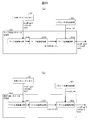
- FIG. 1 is a diagram showing an example of a generated code amount for each picture when a certain moving image is coded.
- the horizontal axis indicates time (continuous pictures), and the vertical axis indicates the generated code amount of each picture.
- FIG. 1 is a diagram illustrating an example of a generated code amount for each picture when a certain moving image is encoded, in which the horizontal axis indicates time (continuous pictures) and the vertical axis indicates the generated code amount of each picture.
- an intra-picture I-picture
- intra-refresh is performed in which only a part of one picture is intra-predicted and other areas are inter-predicted (there may be areas for intra prediction). There is a method called.
- an object of the present invention is to reduce the delay while reducing the encoding efficiency as compared with an I picture without impairing the functionality of random access.
- An object of the present invention is to provide a mechanism for realizing video encoding and decoding.
- a video decoding device divides a picture into a restricted region and a non-restricted region, and performs intra prediction on blocks included in the restricted region by referring to only pixels in the restricted region in the picture, or , Prediction using inter prediction referring to a restricted reference region of a reference picture of the picture, and intra prediction referring to decoded pixels in the picture for blocks included in the unrestricted region, or Prediction is performed using inter prediction referring to a reference picture, and after decoding the picture, the restricted area of the picture is set as the restricted reference area.
- a refresh mechanism in a moving image, to generate encoded data that is randomly accessible and has a small variation in code amount while suppressing a decrease in encoding efficiency. .
- encoding at a substantially constant bit rate can be realized through encoded data, and a delay occurring for each I picture can be avoided.
- FIG. 9 is a diagram illustrating an example of a generated code amount for each picture when a certain moving image is encoded. It is a figure which shows the hierarchical structure of the data of an encoding stream. It is a figure which shows the example of CTU division.
- FIG. 3 is a conceptual diagram illustrating an example of a reference picture and a reference picture list. It is the schematic which shows the kind (mode number) of an intra prediction mode. It is a figure explaining a restricted area and an unrestricted area of the present invention.
- FIG. 3 is a diagram illustrating a range in which a target block according to the present invention can be referred to. It is a figure explaining setting of a restricted reference area.
- FIG. 3 is a diagram illustrating an example of a generated code amount for each picture when a certain moving image is encoded. It is a figure which shows the hierarchical structure of the data of an encoding stream. It is a figure which shows the example of CTU division.
- FIG. 3 is a
- FIG. 3 is a diagram illustrating a stepwise refresh area according to the present invention.
- FIG. 4 is a diagram illustrating a new refresh area, a restricted area, and an unrestricted area according to the present invention.
- FIG. 4 is a diagram illustrating a new refresh area according to the present invention.
- FIG. 4 is a diagram illustrating a relationship between a new refresh area and a CU.
- FIG. 4 is a diagram illustrating types of a new refresh area according to the present invention.
- FIG. 4 is another diagram illustrating a new refresh area according to the present invention.
- FIG. 4 is a diagram illustrating syntax required for stepwise refresh.
- FIG. 4 is a diagram illustrating a relationship between a restriction area and an overlap area.
- FIG. 3 is a schematic diagram illustrating a configuration of a moving image decoding device.
- FIG. 2 is a block diagram illustrating a configuration of a video encoding device. It is a schematic diagram showing the composition of an inter prediction parameter decoding part.
- FIG. 3 is a schematic diagram illustrating configurations of a merge prediction parameter derivation unit and an AMVP prediction parameter derivation unit.
- FIG. 4 is a schematic diagram illustrating a configuration of an intra prediction parameter decoding unit.
- FIG. 3 is a schematic diagram illustrating a configuration of an inter prediction image generation unit. It is a figure explaining boundary padding and boundary motion vector clipping.
- FIG. 3 is a diagram illustrating a reference area used for intra prediction. It is a figure showing composition of an intra prediction picture generation part.
- FIG. 4 is a diagram illustrating a reference pixel of a reference pixel filter. It is a figure which shows the relationship between the restricted area
- FIG. 3 is a schematic diagram illustrating a configuration of an inter prediction parameter encoding unit.
- FIG. 3 is a schematic diagram illustrating a configuration of an intra prediction parameter encoding unit.
- FIG. 1 is a diagram illustrating a configuration of a transmission device equipped with a video encoding device according to the present embodiment and a reception device equipped with a video decoding device. (a) shows a transmitting device equipped with a moving picture encoding device, and (b) shows a receiving device equipped with a moving picture decoding device.
- FIG. 1 is a diagram illustrating a configuration of a transmission device equipped with a video encoding device according to the present embodiment and a reception device equipped with a video decoding device. (a) shows a transmitting device equipped with a moving picture encoding device
- FIG. 1 is a diagram illustrating a configuration of a recording device equipped with a moving image encoding device according to the present embodiment and a playback device equipped with a moving image decoding device.
- (a) shows a recording device equipped with a video encoding device
- (b) shows a playback device equipped with a video decoding device.
- 1 is a schematic diagram illustrating a configuration of an image transmission system according to an embodiment.
- FIG. 4 is a diagram illustrating a deblocking filter.
- FIG. 4 is a diagram illustrating a relationship between a restricted area and a deblocking filter.
- FIG. 4 is a diagram illustrating a relationship between a restriction region and a deblocking filter region.
- 5 is a flowchart illustrating an operation of a deblocking filter.
- FIG. 32 is a schematic diagram showing the configuration of the image transmission system 1 according to the present embodiment.
- the image transmission system 1 is a system that transmits an encoded stream obtained by encoding an encoding target image, decodes the transmitted encoded stream, and displays an image.
- the image transmission system 1 includes a moving image coding device (image coding device) 11, a network 21, a moving image decoding device (image decoding device) 31, and a moving image display device (image display device) 41. .
- the image T is input to the video encoding device 11.
- the network 21 transmits the coded stream Te generated by the video encoding device 11 to the video decoding device 31.
- the network 21 is the Internet, a wide area network (WAN: Wide Area Network), a small network (LAN: Local Area Network), or a combination thereof.
- the network 21 is not limited to a two-way communication network, but may be a one-way communication network for transmitting broadcast waves such as terrestrial digital broadcasting and satellite broadcasting. Further, the network 21 may be replaced by a storage medium that records an encoded stream Te such as a DVD (Digital Versatile Disc: registered trademark) and a BD (Blu-ray (registered trademark) Disc: registered trademark).
- the video decoding device 31 decodes each of the encoded streams Te transmitted by the network 21, and generates one or a plurality of decoded images Td.
- the video display device 41 displays all or a part of one or a plurality of decoded images Td generated by the video decoding device 31.
- the moving image display device 41 includes a display device such as a liquid crystal display and an organic EL (Electro-luminescence) display. Examples of the form of the display include stationary, mobile, and HMD.
- a display device such as a liquid crystal display and an organic EL (Electro-luminescence) display. Examples of the form of the display include stationary, mobile, and HMD.
- X? Y: z is a ternary operator that takes y when x is true (other than 0) and z when x is false (0).
- Abs (a) is a function that returns the absolute value of a.
- Int (a) is a function that returns the integer value of a.
- Floor (a) is a function that returns the largest integer less than or equal to a.
- Ceil (a) is a function that returns the largest integer greater than or equal to a.
- a / d represents the division of a by d (rounded down to the decimal point).
- FIG. 2 is a diagram showing a hierarchical structure of data in the encoded stream Te.
- the coded stream Te illustratively includes a sequence and a plurality of pictures constituting the sequence.
- (A) to (f) of FIG. 2 respectively show an encoded video sequence defining a sequence SEQ, an encoded picture defining a picture PICT, an encoded slice defining a slice S, and an encoded slice defining slice data.
- FIG. 3 is a diagram illustrating data, an encoding tree unit CTU included in encoded slice data, and an encoding unit CU included in the encoding tree unit.
- the encoded video sequence In the encoded video sequence, a set of data referred to by the video decoding device 31 to decode the sequence SEQ to be processed is defined. As shown in FIG. 2A, the sequence SEQ includes a video parameter set (Video Parameter Set), a sequence parameter set SPS (Sequence Parameter Set), a picture parameter set PPS (Picture Parameter Set), a picture PICT, and additional extension.
- Information Contains SEI (Supplemental Enhancement Information).
- the video parameter set VPS includes, in a moving image composed of a plurality of layers, a set of encoding parameters common to a plurality of moving images and a plurality of layers included in the moving image and encoding parameters related to individual layers. Sets are defined.
- the sequence parameter set SPS defines a set of encoding parameters that the video decoding device 31 refers to for decoding the target sequence. For example, the width and height of a picture are defined. Note that a plurality of SPSs may exist. In that case, one of the plurality of SPSs is selected from the PPS.
- the picture parameter set PPS defines a set of encoding parameters referred to by the video decoding device 31 to decode each picture in the target sequence. For example, a reference value (pic_init_qp_minus26) of a quantization width used for decoding a picture and a flag (weighted_pred_flag) indicating application of weighted prediction are included. Note that a plurality of PPSs may exist. In that case, any one of the plurality of PPSs is selected from each picture in the target sequence.
- the picture PICT includes slice 0 to slice NS-1 (NS is the total number of slices included in the picture PICT).
- Coding slice In the coded slice, a set of data referred to by the video decoding device 31 to decode the processing target slice S is defined.
- the slice includes a slice header and slice data as shown in FIG. 2 (c).
- the slice header includes a group of encoding parameters referred to by the video decoding device 31 in order to determine a decoding method for the target slice.
- the slice type designation information (slice_type) that designates a slice type is an example of an encoding parameter included in a slice header.
- the slice types that can be specified by the slice type specification information include (1) an I slice using only intra prediction at the time of encoding, (2) a P slice using unidirectional prediction or intra prediction at the time of encoding, (3) B-slice using unidirectional prediction, bidirectional prediction, or intra prediction at the time of encoding.
- the inter prediction is not limited to uni-prediction and bi-prediction, and a prediction image may be generated using more reference pictures.
- P and B slices they indicate slices including blocks that can use inter prediction.
- the slice header may include a reference (pic_parameter_set_id) to the picture parameter set PPS.
- the slice data includes a CTU as shown in FIG. 2 (d).
- the CTU is a block of a fixed size (for example, 64 ⁇ 64) constituting a slice, and may be called a maximum coding unit (LCU: Largest Coding Unit).
- a set of data referred to by the video decoding device 31 for decoding the processing target CTU is defined.
- the CTU is based on a recursive quadtree (QT (Quad Tree)), binary (BT (Binary Tree)) or ternary (TT (Ternary Tree)) coding process. Is divided into coding units CU, which are typical units.
- the BT division and the TT division are collectively called a multi-tree division (MT (Multi Tree) division).
- MT Multi Tree division
- a tree-structured node obtained by recursive quad-tree division is called a coding node.
- Intermediate nodes of the quadtree, the binary tree, and the ternary tree are coding nodes, and the CTU itself is defined as the highest coding node.
- CT includes, as CT information, a QT split flag (cu_split_flag) indicating whether or not to perform QT split, an MT split mode (split_mt_mode) indicating the presence / absence of MT split, an MT split direction (split_mt_dir) indicating a split direction of the MT split, An MT split type (split_mt_type) indicating the split type of the MT split is included.
- cu_split_flag, split_mt_flag, split_mt_dir, split_mt_type ⁇ are transmitted for each coding node.
- the coding node is divided into four coding nodes (FIG. 3 (b)).
- cu_split_flag is 0, if split_mt_flag is 0, the coding node is not divided and has one CU as a node (FIG. 3 (a)).
- CU is a terminal node of the coding node, and is not further divided.
- the CU is a basic unit of the encoding process.
- split_mt_flag the encoded node is divided into MTs as follows.
- split_mt_type is 0, when split_mt_dir is 1, the coding node is horizontally divided into two coding nodes (FIG. 3 (d)), and when split_mt_dir is 0, the coding node is vertical to the two coding nodes. It is divided (Fig. 3 (c)).
- split_mt_type is 1, if split_mt_dir is 1, the coding node is horizontally divided into three coding nodes (FIG. 3 (f)), and if split_mt_dir is 0, the coding node becomes three coding nodes. (Fig. 3 (e)).
- the CU size is 64x64 pixels, 64x32 pixels, 32x64 pixels, 32x32 pixels, 64x16 pixels, 16x64 pixels, 32x16 pixels, 16x32 pixels, 16x16 pixels, 64x8 pixels, 8x64 pixels 32x8 pixels, 8x32 pixels, 16x8 pixels, 8x16 pixels, 8x8 pixels, 64x4 pixels, 4x64 pixels, 32x4 pixels, 4x32 pixels, 16x4 pixels, 4x16 pixels, 8x4 pixels, 4x8 pixels, and any of 4x4 pixels .
- a set of data referred to by the video decoding device 31 to decode the CU to be processed is defined.
- the CU includes a CU header CUH, a prediction parameter, a conversion parameter, a quantized transform coefficient, and the like.
- the prediction mode and the like are defined in the CU header.
- the prediction process is performed in units of CUs, or in units of sub-CUs obtained by further dividing the CU.
- the sizes of the CU and the sub-CU are equal, there is one sub-CU in the CU.
- the CU is split into sub-CUs. For example, if the CU is 8x8 and the sub-CU is 4x4, the CU is divided into four sub-CUs, which are divided into two horizontal parts and two vertical parts.
- Intra prediction is prediction within the same picture
- inter prediction refers to prediction processing performed between different pictures (for example, between display times and between layer images).
- the quantized transform coefficients may be entropy-coded in subblock units such as 4 ⁇ 4.
- the prediction image is derived from prediction parameters associated with the block.
- the prediction parameters include intra prediction and inter prediction prediction parameters.
- the inter prediction parameter includes a prediction list use flag predFlagL0, predFlagL1, a reference picture index refIdxL0, refIdxL1, and a motion vector mvL0, mvL1.
- the prediction list use flags predFlagL0 and predFlagL1 are flags indicating whether reference picture lists called L0 list and L1 list are used, respectively. When the value is 1, the corresponding reference picture list is used.
- a flag other than 0 for example, 1) is XX, 0 is not XX, and logical negation, logical product, etc. Treat 1 as true and 0 as false (the same applies hereinafter).
- other values can be used as a true value and a false value in an actual device or method.
- inter prediction parameters include, for example, merge flag merge_flag, merge index merge_idx, inter prediction identifier inter_pred_idc, reference picture index refIdxLX, prediction vector index mvp_LX_idx, and difference vector mvdLX.
- the reference picture list is a list including reference pictures stored in the reference picture memory 306.
- FIG. 4 is a conceptual diagram showing an example of a reference picture and a reference picture list in a picture structure for low delay.
- a rectangle is a picture
- an arrow is a picture reference relationship
- a horizontal axis is time
- I, P, and B in the rectangle are intra pictures
- uni-prediction pictures bi-prediction pictures
- numbers in the rectangle are decoding. Indicates the order.
- the decoding order of pictures is I0, P1 / B1, P2 / B2, P3 / B3, P4 / B4, and the display order is the same.
- FIG. (B) in the figure shows an example of a reference picture list of picture B3 (target picture).
- the reference picture list is a list representing reference picture candidates, and one picture (slice) may have one or more reference picture lists.
- the target picture B3 has two reference picture lists, an L0 list RefPicList0 and an L1 list RefPicList1.
- the reference picture list is only the L0 list.
- LX is a description method used when L0 prediction and L1 prediction are not distinguished, and hereinafter, LX is replaced with L0 and L1 to distinguish between parameters for the L0 list and parameters for the L1 list.
- the prediction parameter decoding (encoding) method includes a merge prediction (merge) mode and an AMVP (Adaptive Motion Vector Prediction) mode.
- a merge flag merge_flag is a flag for identifying these.
- the merge prediction mode is a mode in which a prediction list use flag predFlagLX (or an inter prediction identifier inter_pred_idc), a reference picture index refIdxLX, and a motion vector mvLX are not included in encoded data but are derived from prediction parameters of already processed neighboring blocks.
- the merge index merge_idx is an index indicating which prediction parameter is used as the prediction parameter of the target block among the prediction parameter candidates (merge candidates) derived from the processed block.
- the AMVP mode is a mode in which an inter prediction identifier inter_pred_idc, a reference picture index refIdxLX, and a motion vector mvLX are included in encoded data.
- the motion vector mvLX is encoded as a prediction vector index mvp_LX_idx for identifying the prediction vector mvpLX and a difference vector mvdLX.
- the inter prediction identifier inter_pred_idc is a value indicating the type and number of reference pictures, and takes one of PRED_L0, PRED_L1, and PRED_BI.
- PRED_L0 and PRED_L1 indicate uni-prediction using one reference picture managed by the L0 list and the L1 list, respectively.
- PRED_BI indicates bi-prediction BiPred using two reference pictures managed by the L0 list and the L1 list.
- the motion vector mvLX indicates a shift amount between blocks on two different pictures.
- the prediction vector and the difference vector related to the motion vector mvLX are called a prediction vector mvpLX and a difference vector mvdLX, respectively.
- the intra prediction parameters include a luminance prediction mode IntraPredModeY and a color difference prediction mode IntraPredModeC.
- FIG. 5 is a schematic diagram showing types (mode numbers) of intra prediction modes. As shown in the figure, there are, for example, 67 types (0 to 66) of intra prediction modes. For example, Planar prediction (0), DC prediction (1), Angular prediction (2-66). Further, for the color difference, an LM mode (67 to 72) may be added.
- ⁇ ⁇ Syntax elements for deriving intra prediction parameters include, for example, prev_intra_luma_pred_flag, mpm_idx, rem_selected_mode_flag, rem_selected_mode, rem_non_selected_mode, and the like.
- MPM prev_intra_luma_pred_flag is a flag indicating whether or not the luminance prediction mode IntraPredModeY of the target block matches the MPM (Most Probable Mode).
- MPM is a prediction mode included in the MPM candidate list mpmCandList [].
- the MPM candidate list is a list that stores candidates estimated to have a high probability of being applied to the target block from the intra prediction mode of a neighboring block and a predetermined intra prediction mode.
- the prev_intra_luma_pred_flag is 1, the luminance prediction mode IntraPredModeY of the target block is derived using the MPM candidate list and the index mpm_idx.
- IntraPredModeY mpmCandList [mpm_idx] (REM)
- the intra prediction mode is selected from the remaining modes RemIntraPredMode excluding the intra prediction mode included in the MPM candidate list from the entire intra prediction mode.
- An intra prediction mode that can be selected as RemIntraPredMode is called “non-MPM” or “REM”.
- the flag rem_selected_mode_flag is a flag for specifying whether to refer to the rem_selected_mode to select the intra prediction mode or to refer to the rem_non_selected_mode to select the intra prediction mode.
- RemIntraPredMode is derived using rem_selected_mode or rem_non_selected_mode.
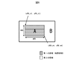
- FIG. 6 is a diagram for explaining the region A and the region B of the present invention.
- the areas A and B in the picture are set.
- the region A can be predicted only from the region A, and processing such as padding is performed outside the region.
- the area B can be predicted from the entire picture including the area A.
- the prediction processing refers to intra prediction, inter prediction, loop filter processing, and the like.
- the area A since the encoding and decoding processes are closed in the area A, only the area A can be decoded.
- the area A is referred to as a restricted area (first area, control area, clean area, refreshed area, area A).
- an area other than the restricted area is also referred to as a non-restricted area (second area, non-control area, dirty area, unrefreshed area, area B, outside the restricted area).
- an area that is encoded / decoded from only intra prediction and an area that has already been encoded in intra prediction is a restricted area.
- the region to be coded / decoded is also the restricted region.
- a region to be coded / decoded with reference to a restricted region in a reference picture is also a restricted region. That is, the restricted area is an area that is encoded and decoded with reference to the restricted area.
- the upper left position of the restricted area is indicated by (xRA_st, yRA_st), the lower right position by (xRA_en, yRA_en), and the size by (wRA, hRA). Since the position and the size have the following relationship, the other may be derived from one.
- xRA_en xRA_st + wRA-1
- yRA_en yRA_st + hRA-1
- the upper left position of the restricted reference area at time j is (xRA_st [j], yRA_st [j])
- the lower right position is (xRA_en [j], yRA_en [j])
- the size is (wRA [j], hRA [ j]).
- the position of the restricted reference area of the reference picture Ref is (xRA_st [Ref], yRA_st [Ref])
- the lower right position is (xRA_en [Ref], yRA_en [Ref]
- the size is (wRA [Ref], hRA [ Ref]).
- the following determination formula may be used.
- the upper left coordinate of the current block Pb is (xPb, yPb)
- the width and height are bW and bH
- the following determination formula may be used.
- the moving picture coding device and the moving picture decoding device in this specification perform the following operations.
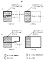
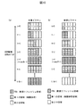
- FIG. 7 is a diagram showing a range in which a restricted region can be referred to in intra prediction, inter prediction, and a loop filter according to the present invention.
- FIG. 7A shows a range in which the target block included in the restricted area can be referred to.
- the already encoded / decoded region included in the restricted region in the same picture (target picture) as the target block is a range in which the target block can be referred to by intra prediction, inter prediction, and a loop filter.
- the restricted region (restricted reference region) in the reference picture is a range in which the target block can be referred to by the inter prediction and the loop filter.
- FIG. 7B shows a range in which the target block included in the unrestricted area can be referred to.
- the already encoded / decoded region in the current picture is a range in which the current block can be referred to in intra prediction and inter prediction.
- all the regions in the reference picture are in a range that can be referred to in inter prediction.
- the target block included in the restricted region performs intra prediction referring only to the pixels of the restricted region in the target picture, or performs inter prediction referring to the restricted reference region of the reference picture.
- the target block included in the restricted region is The coding of the target block is performed by referring to the coding parameters (for example, the intra prediction direction, the motion vector, and the reference picture index) of the restricted area in the current picture or by referring to the coding parameters of the restricted reference area of the reference picture. Derivation parameters are derived.
- loop filter processing is performed with reference to only the pixels in the restricted area in the target picture.
- prediction parameters (intra prediction mode, motion vector) of a target block may be derived using prediction parameters of an adjacent region.
- the following processing may be performed.
- intra prediction and inter prediction if the target block is a restricted area (IsRA (xPb, yPb) is true) and the reference position (xNbX, yNbX) of the block adjacent to the target block is an unrestricted area (IsRA (xNbX, yNbX) is false In the case of), the value of the adjacent block is not used for deriving the prediction parameter.
- the target block is a restricted area (IsRA (xPb, yPb) is true) and the reference position (xNbX, yNbX) of an adjacent block of the target block is a restricted area (IsRA (xNbX, yNbX) is true)
- the position (xNbX, yNbX) is used for deriving a prediction parameter.
- the present invention may be applied to loop filter processing.
- the determination of the restricted area may be used for the entire determination outside the screen, similarly to the determination outside the screen or the unit of parallel processing (slice boundary, tile boundary).
- the target block is a restricted area (IsRA (xPb, yPb) is true) and the reference position (xNbX, yNbX) of the target block is a restricted area (IsRA (xNbX, yNbX) is true)
- IsRA xNbX, yNbX
- the target block is in the screen, and the reference position is not in the same parallel processing unit as the target block, and the target block is in the unrestricted area, or the reference position (xNbX, yNbX) of the target block is restricted.
- availableNbX 1
- the prediction parameter of the reference position is used to derive the prediction parameter of the target block, and the loop filter is used.
- the motion compensation unit derives the case where the reference pixel is in the restricted reference area using the following determination formula.
- the following determination formula may be used.
- the motion compensation unit may clip the reference pixel to a position in the restricted area using the following equation.
- xRef Clip3 (xRA_st [j], xRA_en [j], xRef)
- yRef Clip3 (yRA_st [j], yRA_en [j], yRef)
- the following derivation formula may be used.
- xRef Clip3 (xRA_st [j], xRA_st [j] + wRA [j] -1, xRef)
- yRef Clip3 (yRA_st [j], yRA_st [j] + hRA [j] -1, yRef)
- the position of the restricted area is transmitted from the moving picture encoding apparatus to the moving picture decoding apparatus based on the stepwise refresh information described later. Note that the position and size of the restricted area are not derived according to time (e.g., POC), and after decoding the current picture or at the start of decoding of the current picture, the reference picture Ref in the reference memory may be set. Good. In this case, by specifying the reference picture Ref, the position and size of the restricted area can be derived.
- (Set / update restricted reference area) The restricted area of a picture is set as the restricted reference area when a picture is used as a reference picture.
- a restricted reference area may be set.
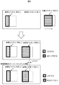
- FIG. 8 is a diagram illustrating updating of the restricted reference area of the reference picture in the reference memory.
- the restricted reference area of the reference picture j in the reference memory is the upper left coordinate (xRA_st [j], yRA_st [j]), the lower right coordinate (xRA_en [j], yRA_en [j]), and the size (wRA [j], hRA [j]), the restricted area of the target picture at time i, that is, upper left coordinates (xRA_st [i], yRA_st [i]), lower right coordinates (xRA_en [i], yRA_en [i]), size (wRA [i], hRA [i]).
- the restricted reference area when storing the reference picture i in the reference memory may be as follows.
- Restricted reference area of reference picture j upper left coordinates (xRA_st [j], yRA_st [j]), lower right coordinates (xRA_en [j], yRA_en [j]), size (wRA [j], hRA [j])
- Restricted reference area of reference picture i upper left coordinates (xRA_st [i], yRA_st [i]), lower right coordinates (xRA_en [i], yRA_en [i]), size (wRA [i], hRA [i])
- the restricted reference area of the reference picture may be smaller than the time when the current picture is decoded.
- Restricted reference area of reference picture j upper left coordinates (xRA_st [j], yRA_st [j]), lower right coordinates (xRA_en [j], yRA_en [j]), size (wRA [j], hRA [j])
- Restricted reference area of reference picture i upper left coordinates (xRA_st [i], yRA_st [i]), lower right coordinates (xRA_en [i] -wOVLP, yRA_en [i]), size (wRA [i] -wOVLP, hRA [ i])
- a stepwise decoded refresh picture (Sequentially Decoder Refresh, SDR picture)
- all areas that can be referenced from the restricted area in the reference picture (restricted reference area) are cleared to be unreferenceable.
- a flag indicating whether to set a restricted reference area may be set to 0, or the restricted reference area may be eliminated by the following equation.
- the restricted area in the reference picture is also called a restricted reference area (first reference area, non-control reference area, clean reference area, refreshed reference area, reference area A). Also referred to as a non-restricted reference area (second reference area, non-control reference area, dirty reference area, unrefreshed reference area, reference area B).
- the outline of the refresh (stepwise refresh, stepwise decode refresh) of the present invention will be described.
- the gradual refresh of the present invention is a stepwise transmission of a restricted area composed of intra prediction, and in a subsequent picture, expanding the size of the restricted area to the entire screen to gradually reduce the entire picture.
- Refresh technology Note that, in the present picture, an area newly added as a restricted area is referred to as a new refresh area in this specification.
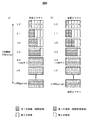
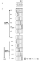
- FIG. 9 is a diagram for explaining refresh (stepwise refresh) of the present invention.
- a restricted area (new refresh area FRA) composed of intra prediction is inserted in a picture serving as a refresh start point.
- the picture that is the starting point of this refresh is called an SDR picture (Sequentially Decoder Refresh, random access point).
- SDR picture Sequially Decoder Refresh, random access point.
- FRA Form Refresh Area
- FIG. 9 (a) shows the restricted area at each time t.
- a restricted region composed entirely of intra prediction is decoded.
- all restricted reference areas in the reference picture are cleared to make reference impossible.
- FIG. 9B shows a restricted reference area on a reference picture.
- the restricted reference area is indicated by a horizontal line area.
- a configuration in which SDR pictures are periodically inserted is also possible. In this specification, an SDR picture is inserted for each SDR cycle SDRperiod.
- FIG. 10 is a view clearly showing an area (new refresh area) to be newly added to the target picture in the restricted area.
- the entire picture can be refreshed by adding a new refresh area FRA step by step and setting a new restricted area including the added FRA.
- all parts of the new refresh area FRA may be an area (Intra Refresh Area, IRA) consisting only of intra prediction.
- IRA Intra Refresh Area
- the restricted area must not refer to a picture before the first picture in the SDR cycle.
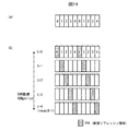
- FIG. 11A shows an example in which one picture is divided into numIR areas (refresh unit areas).
- numIR 5.
- FIG. 11B is a diagram showing an example in which a new refresh area FRA (hatched area in the figure) added to the restricted area shifts from left to right.
- FRA new refresh area
- the FRA shifts to the right
- the moving picture decoding apparatus decodes the intra-predicted restricted area (FRA) in the SDR picture, and generates an appropriate image by error concealment in the area other than the restricted area. Even in the picture following the SDR picture, the intra-prediction restricted area and the restricted area referring to the restricted reference area of the reference picture are decoded, and in the other areas, an appropriate image is generated by error concealment. By repeating this operation until the new restricted area (for example, FRA) moves from one end of the picture to the entire restricted picture (for numIR pictures), the entire picture can be correctly decoded.
- FRA new restricted area
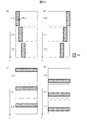
- FIG. 12 is a diagram showing an FRA region.
- FIG. 12 (a) shows a case of shifting from left to right.
- the FRA is a rectangle having a width wIR and a height hPict with (xIR, yIR) as the upper left coordinate.
- the width wIR of the FRA is an integral multiple of the minimum CU width minCU.
- wIR minCU * a
- a is a positive integer.
- FIG. 12 (b) shows a case of shifting from top to bottom.
- the FRA is a rectangle having a height hIR and a width wPict with (xIR, yIR) being the upper left coordinate.
- the height hIR of the FRA is an integral multiple of the minimum CU width minCU.
- hIR minCU * a
- a is a positive integer. That is, the granularity of the width or height of the FRA is equal to or larger than the minimum value minCU of the width or height of the CU, and is set to an integral multiple of minCU.
- FIG. 13 is a diagram illustrating the refresh direction.
- FRA is inserted in the vertical direction and shifted from left to right.
- the upper left coordinates (xIR [t], yIR [t]) and lower right coordinates (xRA_en [t], yRA_en [t]) of the new restricted area of the picture at time t can be expressed as follows.
- Expression IR-1 may also be expressed as follows using a width wOVLP related to a pixel derived with reference to a pixel value or an encoding parameter outside the restricted area.
- the upper left coordinates of the restricted area of the picture at time t can be expressed by (Equation IR-2).
- Expression IR-2 may be expressed as follows using the height hOVLP related to the pixel derived with reference to the pixel value and the encoding parameter other than the restricted area.
- FIG. 13D shows an example in which the FRA is inserted in the horizontal direction and shifted from the bottom to the top.
- FIG. 14 is an example in which the FRA is composed of a plurality of regions.
- the region k is one rectangle on a certain picture, but the region k may be a plurality of rectangles as shown in FIG.
- the restricted area includes a plurality of areas of the picture.
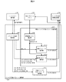
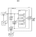
- the video decoding device 31 includes an entropy decoding unit 301, a parameter decoding unit (prediction image decoding device) 302, a loop filter 305, a reference picture memory 306, a prediction parameter memory 307, a prediction image generation unit (prediction image generation device) 308, and an inverse. It is configured to include a quantization / inverse transforming unit 311 and an adding unit 312. In addition, there is also a configuration in which the moving image decoding device 31 does not include the loop filter 305 in accordance with the moving image encoding device 11 described later.
- the parameter decoding unit 302 includes a restriction region control unit 320, and the restriction region control unit 320 includes a header decoding unit 3020, a CT information decoding unit 3021, and a CU decoding unit 3022 (predictive mode decoding unit), not shown.
- the CU decoding unit 3022 further includes a TU decoding unit 3024.
- the header decoding unit 3020 decodes parameter set information such as VPS, SPS, and PPS from the encoded data.
- the header decoding unit 3020 decodes a slice header (slice information) from the encoded data.
- the CT information decoding unit 3021 decodes a CT from the encoded data.
- the CU decoding unit 3022 decodes the CU from the encoded data.
- the TU decoding unit 3024 decodes the QP update information (quantization correction value) and the quantization prediction error (residual_coding) from the encoded data.
- the parameter decoding unit 302 includes an inter prediction parameter decoding unit 303 and an intra prediction parameter decoding unit 304 (not shown).
- the prediction image generation unit 308 includes an inter prediction image generation unit 309 and an intra prediction image generation unit 310.
- CTUs and CUs are used as processing units.
- the present invention is not limited to this example, and processing may be performed in sub-CU units.
- the CTU, CU, and TU may be read as blocks and sub-CUs as sub-blocks, and the processing may be performed on a block or sub-block basis.
- the entropy decoding unit 301 performs entropy decoding on the encoded stream Te input from the outside, and separates and decodes individual codes (syntax elements).
- Entropy coding includes a method of performing variable-length coding of syntax elements using a context (probability model) adaptively selected according to the type of the syntax elements and surrounding conditions, and a predetermined table or There is a method of performing variable-length coding on syntax elements using a calculation formula.
- a representative of the former is CABAC (Context Adaptive Binary Arithmetic Coding).
- the separated codes include prediction information for generating a predicted image, prediction errors for generating a difference image, and the like.
- Entropy decoding section 301 outputs a part of the separated code to parameter decoding section 302.
- the part of the separated code is, for example, a prediction mode predMode, a merge flag merge_flag, a merge index merge_idx, an inter prediction identifier inter_pred_idc, a reference picture index refIdxLX, a prediction vector index mvp_LX_idx, and a difference vector mvdLX.
- Control of which code is to be decoded is performed based on an instruction from the parameter decoding unit 302.
- Entropy decoding section 301 outputs the quantized transform coefficient to inverse quantization / inverse transform section 311.
- FIG. 15 is a diagram illustrating an example of the syntax notified to realize the gradual refresh.
- FIG. 15A shows a syntax (stepwise refresh information) notified by a sequence parameter set (SPS).
- SPS sequence parameter set
- seq_refresh_enable_flag is a flag indicating whether or not to use gradual refresh in subsequent pictures.
- the parameter decoding unit 302 decodes the stepwise refresh information, and the moving picture decoding apparatus decodes the moving picture using the stepwise refresh when the seq_refresh_enable_flag flag is 1, and does not use the stepwise refresh when the seq_refresh_enable_flag flag is 0.
- seq_refresh_enable_flag 1
- the parameter decoding unit 302 decodes seq_refresh_mode, seq_refresh_direction, and seq_refresh_period.
- seq_refresh_mode is a flag indicating the type of gradual refresh shown in FIG.
- the video decoding device inserts a new refresh area (FRA) in the picture in the vertical direction as shown in FIGS. 13A and 13B. As shown in (c) and (d), the FRA inserts the picture horizontally.
- FAA refresh area
- Seq_refresh_direction is a flag indicating the shift direction of the gradual refresh shown in FIG. If seq_refresh_direction is 0, the video decoding apparatus shifts the FRA from left to right or from top to bottom of the picture as shown in FIGS. 13 (a) and 13 (c). If 1, the FRA shifts from right to left or from bottom to top of the picture as shown in FIGS. 13 (b) and (d).
- seq_refresh_period is an SDR cycle SDRperiod, and indicates the number of pictures between random access points.
- FIG. 15 (b) shows the syntax of the gradual refresh information notified by the picture parameter set (PPS).
- PPS picture parameter set
- seq_refresh_mode When seq_refresh_mode is 1 (horizontal rectangular limited area), the x coordinate yIR is set to 0, and the y coordinate yIR is set to seq_refresh_position.
- seq_refresh_size is the size of the FRA, and when seq_refresh_mode is 0, it is set to the FRA width wIR, and when it is 1, it is set to the FRA height hIR.
- seq_refresh_overlap is the size of the area where the FRA position of the previous picture in the decoding order and the FRA position of the current picture overlap, and the overlap width wOVLP when seq_refresh_mode is 0, and the overlap width when seq_refresh_mode is 1, Specifies the wrap height hOVLP. Note that seq_refresh_overlap may be 0.
- the new refresh area (FRA) added to the restricted area in the target picture at time t may overlap (overlap) with the FRA of the picture at time t-1.
- the width wOVLP is an overlapping area.
- the end point of the restricted reference area when the picture at time t is referred to as the reference picture may be derived by subtracting the overlap area as follows.
- the restriction area from which the overlap area is subtracted may be referred to as a filter restriction area (or a post-filter restriction area, an overlap restriction area, or a reference restriction area).
- the derivation formula when seq_refresh_mode is 1 is as follows.
- the moving picture decoding apparatus can acquire the information about the stepwise refresh by decoding the syntax related to the stepwise refresh using the SPS or the PPS. Therefore, the moving picture decoding apparatus can appropriately decode the encoded data by using the stepwise refresh in the decoding of the moving picture at the time of random access.
- the loop filter 305 is a filter provided in the encoding loop, which removes block distortion and ringing distortion and improves image quality.
- the loop filter 305 applies filters such as a deblocking filter 3051, a sample adaptive offset (SAO), and an adaptive loop filter (ALF) to the decoded image of the CU generated by the adding unit 312.
- filters such as a deblocking filter 3051, a sample adaptive offset (SAO), and an adaptive loop filter (ALF) to the decoded image of the CU generated by the adding unit 312.
- the deblocking filter 3051 determines that there is block distortion when a difference between pixel values of pixels adjacent to each other via a block (CTU / CU / TU) boundary is within a predetermined range. Then, an image near the block boundary is smoothed by performing a deblocking process on the block boundary in the decoded image before the deblocking filter.
- the deblocking filter 3051 makes a filter on / off determination for each block. For example, if (Expression DB-1) is satisfied, the target block is filtered.
- FIG. 33 (a) is an example in which block P and block Q are in contact in the vertical direction
- FIG. 33 (b) is an example in which block P and block Q are in contact in the horizontal direction.
- P2k, P1k, and P0k are pixels included in the block P among the blocks P and Q that are in contact with the boundary, and Q0k, Q1k, and Q2k are pixels included in the block Q.
- k indicates the number of the pixel in the block boundary direction.
- ⁇ is a predetermined threshold.
- the deblocking filter 3051 derives the filter strength with respect to the boundary between the block P and the block Q by (Formula DB-2). If all of (Expression DB-2) are satisfied, the deblocking filter 3051 sets the filter strength to "strong", and if not, sets the filter strength to "weak".
- ⁇ is a threshold value depending on the quantization parameter.
- the deblocking filter 3051 refers to three pixels from the boundary indicated by the horizontal line in FIG. 33 (c) in order to determine the on / off of the filter and the strength of the filter in the two blocks bordering the boundary.
- the area of block P filtered with reference to block Q is a random access area. Since decoding sometimes refers to an undetermined pixel value (unrestricted area), decoding cannot be performed normally.
- This application provides a method for generating encoded data that can be randomly accessed and decoding normally by the following method.
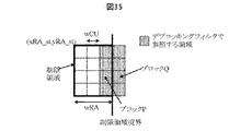
- FIG. 35 is a diagram illustrating a relationship between the restriction area and the deblocking filter.
- the deblocking filter 3051 turns off the filter in a block adjacent to the boundary between the restricted area and the non-restricted area.
- the deblocking filter 3051 determines whether or not the blocks P and Q sandwiching a block boundary (CU boundary, PU boundary, TU boundary) intersect a restricted area boundary.
- XCUQ can be expressed by (Expression DB-4).
- xCUP xRA_st + wRA-wCU (Formula DB-4)
- xCUQ xRA_st + wRA
- the deblocking filter 3051 may use the following determination formula using the coordinates (xP, yP) of the pixels of the block P and the coordinates (xQ, yQ) of the pixels of the block Q.
- the deblocking filter 3051 may turn off the filter for the blocks P and Q in which the x coordinate at the upper left of the block satisfies (Expression DB-4).
- FIG. 36 (a) is a flowchart showing the flow of filter processing of the deblocking filter 3051 of the present embodiment.
- the deblocking filter 3051 checks, based on the upper left coordinates of the target blocks P and Q, whether or not these blocks are adjacent to each other across the restricted area boundary.
- the deblocking filter 3051 turns off the deblocking filter at the boundary of the restricted area, and derives the pixel value of the restricted area included in the restricted area without using the pixel value of the non-restricted area. be able to. Therefore, by turning off the deblocking filter only at the boundary of the restricted area, it is possible to realize low decoding while realizing normal decoding in random access.
- the deblocking filter 3051 turns off the filter only for the block P in the restricted area among the blocks adjacent to each other across the boundary between the restricted area and the non-restricted area. That is, when the x coordinate at the upper left of the block P satisfies the xCUP of (Formula DF-4), the filter is turned off.
- FIG. 36 (b) is a flowchart showing the flow of the filter processing of this embodiment.
- Steps S2202 and S2206 are the same processing as in FIG. 36 (a), and a description thereof will be omitted.
- the deblocking filter 3051 performs the on / off determination of the filter based on (Equation DB-1) in the block Q, and when it is on, derives the filter strength using (Equation DB-1) and obtains (Equation DB- Filter only pixels Q0k, Q1k and Q2k of block Q using 3).
- the deblocking filter 3051 turns off the deblocking filter only for blocks in the restricted area necessary to realize the random access function at the boundary of the restricted area, and turns off the deblocking filter for blocks not required for the random access function. turn on.
- This makes it possible to derive a pixel value of an area referred to as a restricted area in subsequent encoding and decoding processes without using a pixel value of an unrestricted area. Therefore, by turning off the deblocking filter only at the boundary of the restricted area, it is possible to realize low decoding while realizing normal decoding in random access.
- the deblocking filter 3051 forcibly turns off the filter in the filter processing between the restricted area (refresh area, first area) and the non-restricted area (unrefreshed area, second area).
- the deblocking filter 3051 refers to the information of the block Q in the deblocking filter processing in the normal deblocking filter processing, in the derivation of the on / off of the filter, the derivation of the filter strength, and the filtering.
- both blocks sandwiching the restricted area boundary refer to each other in the filter processing, and correct the pixel value. Therefore, if the information of the block Q cannot be obtained from the block P, the decoding process cannot be performed normally.
- the overlap width wOVLP may be the CU width wCU, but the pixels corrected by filtering are part of the block. Therefore, the width wOVLP of the overlap region may be derived from the number of pixels numDFPEL corrected by filtering and the minimum value minC of the CU width as shown in (Equation DB-6).
- xRA_st [k + 1] xRA_st [k] + wRA-wOVLP (Formula DB-7)
- yRA_st [k + 1] yRA_st [k]
- the new refresh area for example, the intra refresh area
- the height hOVLP of the overlap area and the upper left coordinate (xRA_st) of the restricted reference area at time t k + 1 [k + 1], yRA_st [k + 1]
- ⁇ ⁇ Decode the stepwise refresh information and determine whether the target block is in the restricted area.
- intra prediction and inter prediction are performed using only the prediction parameters of the restricted area. Deriving prediction parameters for prediction. Further, intra prediction is performed using only the pixels in the restricted area, and inter prediction is performed using only the pixels in the restricted reference area of the reference image.
- the filtering process may be performed by adding a restriction on the restricted area in a range excluding the area corresponding to the overlap area in the restricted area.
- the minimum CU size or the CU size including the number of pixels required for the filter (or the CU size specified by the syntax) for the non-restricted area (unrefreshed area) side or the restricted area side of the restricted area (refresh area) The CU of (size) is encoded in the same manner as the restricted area.
- the overlap width wOVLP is 8 from (Formula DF-6).
- the overlap width wOVLP is 4.
- the deblocking filter 3051 of the first modification switches the type of filter (long filter, short filter) depending on whether or not the block is in contact with the boundary of the restricted area. Whether or not the block is in contact with the restricted area boundary is determined by (Equation DF-9).
- the upper left coordinate of the restricted area is (xRA_st [k], yRA_st [k]), the width of the restricted area is wRA, the upper left coordinate of the block is (xPb, yPb), and the width of the block is wPb.
- the overlap width can be reduced, and a decrease in coding efficiency can be suppressed.
- it is desirable that the number of taps of the short filter is equal to or smaller than the minimum size of the CU.
- the inter prediction parameter decoding unit 303 decodes the inter prediction parameters based on the code input from the entropy decoding unit 301, with reference to the prediction parameters stored in the prediction parameter memory 307. Further, the inter prediction parameter decoding unit 303 outputs the decoded inter prediction parameter to the prediction image generation unit 308, and stores it in the prediction parameter memory 307.
- FIG. 19A is a schematic diagram illustrating a configuration of the inter prediction parameter decoding unit 303 according to the present embodiment.
- the inter prediction parameter decoding unit 303 includes a parameter decoding control unit 3031, an AMVP prediction parameter deriving unit 3032, an adding unit 3038, a merge prediction parameter deriving unit 3036, and a sub-block prediction parameter deriving unit 3037.
- the AMVP prediction parameter derivation unit 3032, the merge prediction parameter derivation unit 3036, and the sub-block prediction parameter derivation unit 3037 may be collectively referred to as a motion vector derivation unit (motion vector derivation device).
- the parameter decoding control unit 3031 instructs the entropy decoding unit 301 to decode syntax elements related to inter prediction, and syntax elements included in encoded data, for example, a merge flag merge_flag, a merge index merge_idx, an inter prediction identifier inter_pred_idc , Reference picture index refIdxLX, prediction vector index mvp_LX_idx, and difference vector mvdLX.
- the parameter decoding control unit 3031 extracts a merge flag merge_flag.
- the parameter decoding control unit 3031 expresses that a certain syntax element is to be extracted, it means that the decoding of the certain syntax element is instructed to the entropy decoding unit 301 and the corresponding syntax element is read from the encoded data.
- the parameter decoding control unit 3031 extracts the AMVP prediction parameter from the encoded data using the entropy decoding unit 301.
- the AMVP prediction parameters include, for example, an inter prediction identifier inter_pred_idc, a reference picture index refIdxLX, a prediction vector index mvp_LX_idx, and a difference vector mvdLX.
- the AMVP prediction parameter deriving unit 3032 derives a prediction vector mvpLX from a prediction vector index mvp_LX_idx.
- Parameter decoding control section 3031 outputs difference vector mvdLX to adding section 3038.
- the adding unit 3038 adds the prediction vector mvpLX and the difference vector mvdLX to derive a motion vector.
- the parameter decoding control unit 3031 extracts a merge index merge_idx as a prediction parameter related to merge prediction.
- Parameter decoding control section 3031 outputs the extracted merge index merge_idx to merge prediction parameter deriving section 3036.
- FIG. 20 (a) is a schematic diagram showing the configuration of the merge prediction parameter deriving unit 3036 according to the present embodiment.
- the merge prediction parameter derivation unit 3036 includes a merge candidate derivation unit 30361, a merge candidate selection unit 30362, and a merge candidate storage unit 30363.
- the merge candidate storage unit 30363 stores the merge candidates input from the merge candidate derivation unit 30361.
- the merge candidate includes a prediction list use flag predFlagLX, a motion vector mvLX, and a reference picture index refIdxLX. An index is assigned to the merge candidate stored in the merge candidate storage unit 30363 according to a predetermined rule.
- the merge candidate deriving unit 30361 derives a merge candidate using the motion vector of the decoded adjacent block and the reference picture index refIdxLX as they are.
- the merge candidate deriving unit 30361 may apply affine prediction to a space merge candidate derivation process, a temporal merge candidate derivation process, a combined merge candidate derivation process, and a zero merge candidate derivation process described below.
- the merge candidate deriving unit 30361 reads out prediction parameters (predFlagLX, motion vector mvLX, and reference picture index refIdxLX) stored in the prediction parameter memory 307 according to a predetermined rule, and performs merging.
- the method of designating the reference picture is, for example, a method of specifying a neighboring block (for example, a block in contact with a left end L, a left lower end BL, a left upper end AL, an upper end A, and an upper right end AR, respectively) within a predetermined range from the target block. These are the prediction parameters for each.
- Each merge candidate is called L, BL, AL, A, AR.
- Merge candidate derivation unit 30361 when the target block is a restricted area (IsRA (xPb, yPb) is true) and the reference position (xNbX, yNbX) of an adjacent block of the target block is an unrestricted area (IsRA (xNbX, yNbX) In the case of “false”, the value of the adjacent block is not used for deriving the merge candidate.
- IsRA xPb, yPb
- the merge candidate deriving unit 30361 determines that the target block is a restricted area (IsRA (xPb, yPb) is true) and the reference position (xNbX, yNbX) of a block adjacent to the target block is a restricted area (IsRA (xNbX, yNbX) Is true) and the prediction is intra prediction, the position (xNbX, yNbX) is used for deriving a merge candidate.
- IsRA xPb, yPb
- IsRA xPb, yPb If) is true
- B0 available
- availableB0 As 1
- the intra prediction unit 3104 sets the target block to the restricted area (IsRA (xPb, yPb) Is true) and the left adjacent position A0 (xPb-1, yPb + hPb), A1 (xPb- 1, yPb + hPb-1), B2 (xPb-1, yPb-1) of the target block is the restricted area
- the values of the left adjacent positions A0, A1, B2 are used to derive the merge candidate.
- the merging candidate deriving unit 30361 reads the prediction parameter of the block C in the reference image including the lower right CBR of the target block or the coordinates of the center from the prediction parameter memory 307 as the merging candidate, and Store in candidate list mergeCandList [].
- the motion vector of the block C is Add to prediction vector candidates.
- the method of specifying the reference image may be, for example, the reference picture index refIdxLX specified in the slice header, or may be specified using the smallest reference picture index refIdxLX of the adjacent block.
- the merging candidate deriving unit 30361 may derive the position (xColCtr, yColCtr) of the block C and the position (xColCBr, yColCBr) of the block CBR using (formula MRG-1).
- (xPb, yPb) is the upper left coordinate of the target block
- (wPb, hPb) is the width and height of the target block.
- the merge candidate derived by the merge candidate derivation unit 30361 is stored in the merge candidate storage unit 30363.
- the order of storing in the merge candidate list mergeCandList [] is, for example, a spatial merge candidate and a temporal merge candidate, that is, ⁇ L, A, AR, BL, A, COL, COMB0,. It should be noted that reference blocks that cannot be used (the block is intra prediction or the like) are not stored in the merge candidate list.
- the merge candidate selection unit 30362 generates a merge candidate mergeCandList [merge_idx] to which the merge index merge_idx input from the parameter decoding control unit 3031 is assigned, from among the merge candidates included in the merge candidate list stored in the merge candidate storage unit 30363. , As the inter prediction parameter of the target block.
- the merge candidate selection unit 30362 stores the selected merge candidate in the prediction parameter memory 307 and outputs the selected merge candidate to the prediction image generation unit 308.
- FIG. 20 (b) is a schematic diagram showing a configuration of the AMVP prediction parameter deriving unit 3032 according to the present embodiment.
- the AMVP prediction parameter deriving unit 3032 includes a vector candidate deriving unit 3033, a vector candidate selecting unit 3034, and a vector candidate storage unit 3035.
- the vector candidate derivation unit 3033 derives a prediction vector candidate from the motion vector mvLX of the decoded adjacent block stored in the prediction parameter memory 307 according to a predetermined rule, and stores the prediction vector candidate in the prediction vector candidate list mvpListLX [] of the vector candidate storage unit 3035. I do.
- the vector candidate selection unit 3034 selects the motion vector mvpListLX [mvp_LX_idx] indicated by the prediction vector index mvp_LX_idx from the prediction vector candidates of the prediction vector candidate list mvpListLX [] as the prediction vector mvpLX.
- the vector candidate selection unit 3034 outputs the selected prediction vector mvpLX to the addition unit 3038.
- the prediction vector candidate may be derived by scaling a motion vector of a decoded adjacent block in a predetermined range from the target block by a method described later.
- the adjacent block is a block spatially adjacent to the target block, for example, a left block, an upper block, and a region temporally adjacent to the target block, for example, a block including the same position as the target block and having a different display time. Includes regions obtained from prediction parameters.
- Addition unit 3038 calculates motion vector mvLX by adding prediction vector mvpLX input from AMVP prediction parameter derivation unit 3032 and difference vector mvdLX input from parameter decoding control unit 3031.
- the addition unit 3038 outputs the calculated motion vector mvLX to the prediction image generation unit 308 and the prediction parameter memory 307.
- Motion vector Mv reference motion vector
- picture PicMv including block with Mv
- reference picture PicMvRef of Mv scaled motion vector
- picture CurPic including block with sMv
- reference picture CurPicRef referenced by sMv
- sMv may be derived by a derivation function MvScale (Mv, PicMv, PicMvRef, CurPic, CurPicRef) shown in (Expression INTERP-1).
- DiffPicOrderCnt (Pic1, Pic2) is a function that returns the difference between the time information (for example, POC) of Pic1 and Pic2.
- scaling function MvScale (Mv, PicMv, PicMvRef, CurPic, CurPicRef) may be the following equation.
- MvScale (Mv, PicMv, PicMvRef, CurPic, CurPicRef) Mv * DiffPicOrderCnt (CurPic, CurPicRef) / DiffPicOrderCnt (PicMv, PicMvRef) That is, Mv may be scaled according to the ratio of the difference between the time information between CurPic and CurPicRef and the difference between the time information between PicMv and PicMvRef.
- the intra prediction parameter decoding unit 304 decodes an intra prediction parameter, for example, an intra prediction mode IntraPredMode, with reference to the prediction parameter stored in the prediction parameter memory 307 based on the code input from the entropy decoding unit 301.
- the intra prediction parameter decoding unit 304 outputs the decoded intra prediction parameters to the prediction image generation unit 308, and stores the decoded intra prediction parameters in the prediction parameter memory 307.
- the intra prediction parameter decoding unit 304 may derive different intra prediction modes for luminance and chrominance.
- FIG. 21 is a schematic diagram showing a configuration of the intra prediction parameter decoding unit 304 of the parameter decoding unit 302.
- the intra prediction parameter decoding unit 304 includes a parameter decoding control unit 3041, a luminance intra prediction parameter decoding unit 3042, and a chrominance intra prediction parameter decoding unit 3043.
- the parameter decoding control unit 3041 instructs the entropy decoding unit 301 to decode a syntax element, and receives the syntax element from the entropy decoding unit 301. If prev_intra_luma_pred_flag is 1, the parameter decoding control unit 3041 outputs mpm_idx to the MPM parameter decoding unit 30422 in the luminance intra prediction parameter decoding unit 3042. When prev_intra_luma_pred_flag is 0, parameter decoding control section 3041 outputs rem_selected_mode_flag, rem_selected_mode, and rem_non_selected_mode to non-MPM parameter decoding section 30423 of luminance intra prediction parameter decoding section 3042. Also, the parameter decoding control unit 3041 outputs the syntax element of the intra prediction parameter of the chrominance to the chrominance intra prediction parameter decoding unit 3043.
- the luminance intra prediction parameter decoding unit 3042 includes an MPM candidate list deriving unit 30421, an MPM parameter decoding unit 30422, and a non-MPM parameter decoding unit 30423 (decoding unit, deriving unit).
- the MPM parameter decoding unit 30422 derives the luminance prediction mode IntraPredModeY with reference to the MPM candidate list mpmCandList [] and mpm_idx derived by the MPM candidate list derivation unit 30421, and outputs the luminance prediction mode IntraPredModeY.
- the non-MPM parameter decoding unit 30423 derives RemIntraPredMode from the MPM candidate list mpmCandList [] and rem_selected_mode_flag, rem_selected_mode, and rem_non_selected_mode, and outputs the luminance prediction mode IntraPredModeY to the intra prediction image generation unit 310.
- the chrominance intra prediction parameter decoding unit 3043 derives the chrominance prediction mode IntraPredModeC from the syntax element of the chrominance intra prediction parameter, and outputs the same to the intra prediction image generation unit 310.
- pixels in the unrestricted reference region may be referred to in a reference pixel filter or a predicted image generation process described below. Constraints are required.
- the reference picture memory 306 stores the decoded image of the CU generated by the adding unit 312 at a position predetermined for each of the target picture and the target CU.
- the prediction parameter memory 307 stores the prediction parameter at a predetermined position for each CTU or CU to be decoded. Specifically, the prediction parameter memory 307 stores the parameters decoded by the parameter decoding unit 302, the prediction mode predMode separated by the entropy decoding unit 301, and the like.
- the prediction mode predMode, prediction parameters, and the like are input to the prediction image generation unit 308. Further, the predicted image generation unit 308 reads a reference picture from the reference picture memory 306. The prediction image generation unit 308 generates a prediction image of a block or a sub-block in the prediction mode (intra prediction, inter prediction) indicated by the prediction mode predMode, using the prediction parameters and the read reference picture (reference picture block).
- the reference picture block is a set of pixels on the reference picture (referred to as a block because it is usually rectangular), and is a region referred to for generating a predicted image.
- Inter prediction image generation unit 309 uses the inter prediction parameter input from the inter prediction parameter decoding unit 303 and the reference picture to perform a prediction image of a block or sub block by inter prediction. Generate
- FIG. 22 is a schematic diagram showing a configuration of the inter prediction image generation unit 309 included in the prediction image generation unit 308 according to the present embodiment.
- the inter prediction image generation unit 309 includes a motion compensation unit (prediction image generation device) 3091 and a weight prediction unit 3094.
- the motion compensation unit 3091 (interpolated image generation unit), based on the inter prediction parameters (predFlagLX, reference picture index refIdxLX, motion vector mvLX) input from the inter prediction parameter decoding unit 303, Then, an interpolated image (motion-compensated image) is generated by reading a block at a position shifted by the motion vector mvLX from the position of the target block in the reference picture RefLX specified by the reference picture index refIdxLX.
- a filter called a motion compensation filter for generating a pixel at a decimal position is applied to generate a motion compensated image.
- the motion compensation unit 3091 derives an integer position (xInt, yInt) and a phase (xFrac, yFrac) corresponding to the coordinates (x, y) in the predicted block by the following formula.
- the motion compensation unit 3091 derives a temporary image temp [] [] by performing horizontal interpolation processing on the reference picture refImg using an interpolation filter.
- shift1 is a normalization parameter for adjusting the value range
- offset1 1 ⁇ (shift1-1).
- the motion compensation unit 3091 derives an interpolated image Pred [] [] from the temporary image temp [] [] by performing vertical interpolation processing.
- shift2 is a normalization parameter for adjusting the value range
- offset2 1 ⁇ (shift2-1).
- Pred [x] [y] ( ⁇ mcFilter [yFrac] [k] * temp [x] [y + k-NTAP / 2 + 1] + offset2) >> shift2
- the above Pred [] [] is derived for each of the L0 list and the L1 list (referred to as interpolation images PredL0 [] [] and PredL1 [] []), and the interpolation image PredL0 [] []
- an interpolation image Pred [] [] is generated from the interpolation image PredL1 [] [].
- the weight prediction unit 3094 generates a prediction image of the block by multiplying the motion compensation image PredLX by a weight coefficient.
- PredFlagL0 or predFlagL1 is 1 (simple prediction) and weight prediction is not used, the following equation processing is performed to adjust the motion compensation image PredLX (LX is L0 or L1) to the pixel bit number bitDepth. I do.
- Pred [x] [y] Clip3 (0, (1 ⁇ bitDepth) -1, (PredLX [x] [y] + offset1) >> shift1)
- shift1 14-bitDepth
- offset1 1 ⁇ (shift1-1).
- Pred [x] [y] Clip3 (0, (1 ⁇ bitDepth) -1, (PredL0 [x] [y] + PredL1 [x] [y] + offset2) >> shift2)
- shift2 15-bitDepth
- offset2 1 ⁇ (shift2-1).
- the weight prediction unit 3094 derives a weight prediction coefficient w0 and an offset o0 from the encoded data, and performs the processing of the following equation.
- Pred [x] [y] Clip3 (0, (1 ⁇ bitDepth) -1, ((PredLX [x] [y] * w0 + 2 ⁇ (log2WD-1)) >> log2WD) + o0)
- log2WD is a variable indicating a predetermined shift amount.
- the weight prediction unit 3094 derives weight prediction coefficients w0, w1, o0, and o1 from the encoded data, and performs the processing of the following equation.
- Pred [x] [y] Clip3 (0, (1 ⁇ bitDepth) -1, (PredL0 [x] [y] * w0 + PredL1 [x] [y] * w1 + ((o0 + o1 + 1) ⁇ log2WD))>> (log2WD + 1))
- the inter prediction image generation unit 309 outputs the generated prediction image of the block to the addition unit 312.
- the boundary padding is performed as a pixel value of a reference pixel position (xIntL + i, yIntL + j) as a pixel value refImg of the following position xRef + i, yRef + j.
- This is realized by using [xRef + i] [yRef + j]. That is, this is realized by clipping the reference position of the pixel used for generating the interpolated image at the position of the boundary pixel of the restricted reference area of the reference picture (for example, at the left end, upper end, lower end, right end).
- the motion compensation unit 3091 performs the following boundary padding processing. That is, when the X coordinate xIntL + i of the reference position is smaller than the left end of the restricted reference area, the pixel is replaced with the position xRA_st of the left end pixel of the restricted reference area. Similarly, when the X coordinate xIntL + i of the reference position is larger than the right end of the restricted reference area, the X coordinate is replaced with the position xRA_en of the right end pixel of the restricted reference area.
- the Y coordinate yIntL + j is smaller than the upper end of the restricted reference area, it is replaced with the upper pixel position yRA_st, and if the Y coordinate yIntL + j is larger than the lower end of the restricted reference area, it is replaced with the lower pixel position yRA_en.
- xRef + i Clip3 (xRA_st, xRA_en, xIntL + i) (Expression INTERP-2)
- yRef + j Clip3 (yRA_st, yRA_en, yIntL + j)
- the motion compensation unit 3091 derives the coordinates of the reference pixel using (Equation INTERP-3).
- xRef + i Clip3 (0, wRA [k] -1, xIntL + i) (Expression INTERP-3)
- yRef + j Clip3 (0, hPict-1, yIntL + j)
- hPict is the height of the picture.
- xIntL and yIntL are (xPb, yPb) as the upper left coordinate of the target block based on the upper left coordinate of the picture and (mvLX [0], mvLX [1]) as the motion vector (formula INTERP-3 ′). May be used to derive the coordinates of the reference pixel.
- MVBIT indicates that the accuracy of the motion vector is 1 / MVBIT pel.
- xRef + i Clip3 (wRA [k], wPict-1, xIntL + i) (Expression INTERP-2 ′)
- yRef + j Clip3 (0, hPict-1, yIntL + j)
- xRA_st wRA [k]
- xRA_en wPict-1
- xRef + i Clip3 (0, wPict-1, xIntL + i) (Expression INTERP-4)
- yRef + j Clip3 (0, yRA_en, yIntL + j)
- wPict is the width of the picture.
- padding is performed using the boundary pixels of the restricted reference area as described above, so that the motion vector in the inter prediction in the restricted area points outside the restricted reference area of the reference picture (unrestricted reference area).
- the reference pixel is replaced using the pixel value in the restricted reference area, normal decoding processing after the random access point can be realized even in inter prediction.
- the motion compensation unit 3091 replaces pixels in the non-restricted reference area with pixels in the restricted reference area in image generation processing using a motion vector pointing out of the restricted reference area in inter prediction of the restricted area (padding). ).
- Motion vector restriction of restricted reference area Another method for generating a predicted image by referring to only pixels in the restricted reference area when referring to a reference picture is boundary motion vector restriction.
- the motion vector is limited (clipped) so that the position (xIntL + i, yIntL + j) of the reference pixel falls within the restricted reference area.
- the upper left coordinates (xPb, yPb) of the target block at time t k
- the position of the restricted reference area of the reference picture at time j are represented by (xRA_st [j]
- the block motion vector mvLX is input and the restricted motion vector mvLX is output.
- the limitation of the motion vector mvLX is shown in (Equation 1)
- ClipRA (mvLX) Clip3 (xRA_st [j] + (NTAP2-1-yPb) ⁇ log2 (MVBIT), (yRA_st [j] +
- mvLX [0] Clip3 ((NTAP2-1-xPb) ⁇ log2 (MVBIT), (wRA [k] -NTAP2-xPb-wPb) ⁇ log2 (MVBIT), mvLX [0]) (Expression INTERP-6 )
- mvLX [1] Clip3 ((NTAP2-1-yPb) ⁇ log2 (MVBIT), (hPict-NTAP2 + 1-yPb-hPb) ⁇ log2 (MVBIT), mvLX [1])
- NTAP is the number of taps of a filter used for generating an interpolation image
- NTAP2 NTAP / 2.
- mvLX [0] Clip3 ((NTAP2-1-xPb) ⁇ log2 (MVBIT), (wPict-NTAP2 + 1-xPb-wPb + 1) ⁇ log2 (MVBIT), mvLX [0]) (Expression INTERP- 8)
- mvLX [1] Clip3 ((NTAP2-1-yPb) ⁇ log2 (MVBIT), (hRA [k] -NTAP2 + 1-yPb-hPb + 1) ⁇ log2 (MVBIT), mvLX [1])
- hRA [k] (hIR-hOVLP) * (k + 1)
- the refresh by limiting the motion vector in this way, the motion vector points within the restricted area of the reference picture. Therefore, even in the inter prediction of the restricted area, normal decoding processing after the random access point can be realized.
- the inter prediction parameter decoding unit 303 and the motion compensation unit 3091 clip the vector indicating the unrestricted reference area within the restricted reference boundary when performing inter prediction.
- the restricted area (restricted reference area) that can be referred to in the inter prediction of the restricted area in the succeeding picture has a range that varies depending on the reference picture (time), as indicated by the horizontal line in FIG. Therefore, when estimating a motion vector of a target block from a motion vector of a peripheral block (hereinafter, an adjacent block) of the target block as in merge prediction, additional processing is required.
- FIG. 23 (b) is a diagram showing an example of the present embodiment.
- the motion vector is mvLX_AL.
- the motion vector mvLX_AL is applied to the motion vector of the target block as a merge candidate, the region points outside the restricted reference region. It can be.
- the merge prediction parameter deriving unit 3036 of the present embodiment derives a merge candidate such that a merge candidate pointing outside the restricted reference area is not included in the merge candidate list.
- the merge prediction parameter deriving unit 3036 determines that the reference picture index and the motion vector are in the restricted reference area in the derived merge candidate (for example, merge candidate N), that is, IsRA If (Pb, mvLX_N) is true, the availabilityN of the merge candidate N is set to 1, and if it is outside the restricted reference area, the availabilityN is set to 0. Alternatively, only the merge candidate with the availability N of 1 may be set in the merge candidate list.
- the merge prediction parameter deriving unit 3036 refers to the generated merge candidate list in order, and the reference picture index and the motion vector in the generated merge candidate list indicate outside the restricted reference area. May be excluded from the merge candidate list.
- a usable merge candidate having a reference picture index and a motion vector to be satisfied is set.
- the merge candidate deriving unit 30361 of the present embodiment uses the following equation to calculate the merge candidate N motion vector mvLX_N May be clipped to a position within the restricted area.
- mvLX [0] ClipRA (mvLX_N [0])
- mvLX [1] ClipRA (mvLX_N [1])
- IsRA Pb, scaledMV
- the reference picture index and the motion vector determine a usable merge candidate using (INTERP-11).
- scaledMV MvScale (mvLX_AL, k, j, k, j ')
- k is the time of the target picture
- j is the time of the reference picture of the adjacent block.
- scaledMV is the motion vector of the adjacent block after scaling, and is derived by (Expression INTERP-1).
- j ′ is the time (POC) of the reference picture indicated by the corrected reference picture index.
- the intra prediction image generation unit 310 performs intra prediction using the intra prediction parameters input from the intra prediction parameter decoding unit 304 and the reference pixels read from the reference picture memory 306.
- the intra-prediction image generation unit 310 reads, from the reference picture memory 306, an adjacent block in the target picture within a predetermined range from the target block.
- the predetermined range is an adjacent block on the left, upper left, upper, and upper right of the target block, and a reference area differs depending on the intra prediction mode.
- the intra-prediction image generation unit 310 generates a prediction image of the target block with reference to the read decoded pixel value and the prediction mode indicated by the intra prediction mode IntraPredMode.
- the intra prediction image generation unit 310 outputs the generated prediction image to the addition unit 312.
- a decoded peripheral area adjacent to the target block is set as a reference area. Then, a predicted image is generated by extrapolating pixels on the reference area in a specific direction.
- the reference region is an L-shaped region including the left and upper (or, further, upper left, upper right, lower left) of the target block (for example, a region indicated by hatched circle pixels in FIG. 24A). It may be set.
- the intra prediction image generation unit 310 includes a target block setting unit 3101, an unfiltered reference image setting unit 3102 (first reference image setting unit), a filtered reference image setting unit 3103 (second reference image setting unit), and a prediction unit 3104 and a predicted image correction unit 3105 (predicted image correction unit, filter switching unit, weight coefficient changing unit).
- the prediction unit 3104 Based on each reference pixel (unfiltered reference image) on the reference area, a filtered reference image generated by applying the reference pixel filter (first filter), and the intra prediction mode, the prediction unit 3104 performs tentative prediction of the target block. An image (predicted image before correction) is generated and output to the predicted image correction unit 3105.
- the predicted image correction unit 3105 corrects the temporary predicted image according to the intra prediction mode, generates a predicted image (corrected predicted image), and outputs the generated predicted image.
- the target block setting unit 3101 sets a target CU as a target block, and outputs information on the target block (target block information).
- the target block information includes at least an index indicating the size, position, luminance or color difference of the target block.
- the unfiltered reference image setting unit 3102 sets a region adjacent to the target block as a reference region based on the size and position of the target block. Next, each decoded pixel value at a corresponding position in the reference picture memory 306 is set to each pixel value (unfiltered reference image, boundary pixel) in the reference area.
- the unfiltered reference is a line r [x] [-1] of decoded pixels adjacent to the upper side of the target block and a row r [-1] [y] of decoded pixels adjacent to the left side of the target block shown in FIG. It is an image.
- the unfiltered reference image r [x] [y] is set by (formula INTRAP-1) using the decoded pixel value u [] [] of the current picture expressed based on the upper left coordinates of the current picture.
- (xPb, yPb) indicates the upper left coordinate of the target block
- maxBS indicates the larger value of the width wPb or the height hPb of the target block.
- a line r [x] [ ⁇ 1] of decoded pixels adjacent to the upper side of the target block and a row r of decoded pixels adjacent to the left side of the target block [-1] [y] is an unfiltered reference image.
- the default value for example, if the pixel bit depth is bitDepth, 1 ⁇ (bitDepth-1)
- bitDepth 1 ⁇
- a referable decoded pixel value existing near the corresponding decoded pixel may be set as an unfiltered reference image.
- "y -1 ..
- the filtered reference image setting unit 3103 applies a reference pixel filter (first filter) to the unfiltered reference image according to the intra prediction mode, and performs a filtered reference of each position (x, y) on the reference area.
- the image s [x] [y] is derived.
- a low-pass filter is applied to the position (x, y) and the unfiltered reference image around the position (x, y) to derive a filtered reference image (FIG. 24 (b)). Note that it is not always necessary to apply a low-pass filter to all intra prediction modes, and a low-pass filter may be applied to some intra prediction modes.
- the unfiltered reference image setting unit 3102 does not use the method of (pixel value setting 1 of the reference area) at the boundary between the restricted area and the non-restricted area, and uses the normal method shown in (Expression INTRAP-1). Is described.
- the filtered reference image setting unit 3103 refers to the pixels in the unrestricted area as the reference pixels as shown in FIG. Do not filter. That is, the pixels in the unrestricted area are set to “not available” as reference pixels. In this case, it is not necessary to apply the reference pixel filter to the pixels in the unrestricted area or all the reference areas above the target block.
- the reference pixel filter is a linear filter that refers to the pixel value of r [maxBS * 2-1] [-1], at least the reference area above the target block is not filtered.
- the reference area without filtering is the reference area on the left side of the target block.
- the reference pixel filter is a linear filter that refers to the pixel value of r [-1] [maxBS * 2-1], at least the reference area on the left side of the target block is not filtered.
- the filter applied to the unfiltered reference image in the reference area in the filtered reference pixel setting unit 3103 is referred to as a “reference pixel filter (first filter)”, whereas the filter to be described later
- the filter that corrects the predicted image is called a “boundary filter (second filter)”.
- the intra prediction unit 3104 generates a tentative predicted image (temporary predicted pixel value, pre-correction predicted image) of the target block based on the intra prediction mode, the unfiltered reference image, and the filtered reference pixel value, and the predicted image correction unit 3105 Output to
- the prediction unit 3104 includes a Planar prediction unit 31041, a DC prediction unit 31042, an Angular prediction unit 31043, and an LM prediction unit 31044 inside.
- the prediction unit 3104 selects a specific prediction unit according to the intra prediction mode, and inputs an unfiltered reference image and a filtered reference image.
- the relationship between the intra prediction mode and the corresponding prediction unit is as follows.
- DC prediction unit 31042 ⁇ Angular prediction ⁇ ⁇ ⁇ Angular prediction unit 31043 ⁇ LM prediction ⁇ ⁇ ⁇ LM prediction unit 31044
- the Planar prediction is performed unless a constraint described later is provided.
- the mode must not be used.
- an intra prediction mode (IntraPredModeY> 50) larger than the vertical prediction mode (50) shown in FIG. 5 must not be used. This is because these modes refer to pixels included in the unrestricted area.
- the Planar prediction unit 31041 linearly adds a plurality of filtered reference images according to the distance between the target pixel position and the reference pixel position to generate a temporary predicted image, and outputs the temporary predicted image to the predicted image correction unit 3105.
- the pixel value q [x] [y] of the tentative prediction image is derived by (Expression INTRAP-4) using the filtered reference pixel value s [x] [y] and the width wPb and height hPb of the target block. You.
- q [x] [y] ((wPb-1-x) * s [-1] [y] + (x + 1) * s [wPb-1] [-1] + (hPb-1-y) * s [x] [-1] + (y + 1) * s [-1] [hPb] + maxBS) >> (log2 (maxBS) +1) (INTRAP-5) Further, the pixel value q [x] [y] of the provisional predicted image may be calculated using s [-1] [hPb-1] instead of s [-1] [hPb].
- the intra prediction unit 3104 A predicted image is generated by Planar prediction by substituting pixels.
- the DC prediction unit 31042 derives a DC prediction value corresponding to an average value of the filtered reference image s [x] [y], and outputs a temporary prediction image q [x] [y] having the DC prediction value as a pixel value. I do.
- the Angular prediction unit 31043 generates a temporary predicted image q [x] [y] using the filtered reference image s [x] [y] in the prediction direction (reference direction) indicated by the intra prediction mode, and Output to 3105.
- Intra prediction section 3104 determines that the target block is a restricted area (IsRA (xPb, yPb) is true) and the reference position (xNbX, yNbX) of a block adjacent to the target block is an unrestricted area ( If IsRA (xNbX, yNbX) is false), the value of the neighboring block is not used for deriving the MPM candidate.
- the target block is a restricted area (IsRA (xPb, yPb) is true) and the reference position (xNbX, yNbX) of a block adjacent to the target block is a restricted area (IsRA (xNbX, yNbX) True), in the case of intra prediction, the position (xNbX, yNbX) is used for the MPM candidate candIntraPredModeX.
- the intra prediction unit 3104 sets the target block to the restricted area (IsRA (xPb, yPb) Is true) and the right adjacent position (xPb + wPb, yPb-1) of the target block is the restricted area (IsRA (xPb + wPb, yPb-1) is true), the MPM candidate is derived from the right adjacent position. Use values.
- the intra prediction unit 3104 sets the target block to the restriction area (IsRA (xPb, yPb) Is true) and the left neighboring position (xPb-1, yPb) of the target block is a restricted area (IsRA (xPb-1, yPb) is true), the value of the left neighboring position is used to derive MPM candidates.
- the reference pixel adjacent to the upper right of the target block is a non-restricted area.
- the width of the target block is wPb
- the intra prediction unit 3104 determines that the target block is a restricted region (IsRA (xPb, yPb) is true) and the right region of the target block is a non-restricted region (IsRA (xPb If + wPb, yPb-1) is false) and a value greater than IntraPredModeVer is derived for the MPM candidate, it is determined that the MPM candidate is not available and is not inserted into the MPM candidate. Also, in this case, if the derived intra prediction mode is larger than IntraPredModeVer, the intra prediction parameter decoding unit 304 may clip to IntraPredModeVer.
- IntraPredMode Min (IntraPredMode, IntraPredModeVer)
- IntraPredMode Max (IntraPredMode, IntraPredModeVer)
- the restricted area is shifted from top to bottom.
- the intra prediction unit 3104 determines that if the upper region (IsRA (xPb, yPb-1) is false) of the target block is an unrestricted region, and a value larger than IntraPredModeHor is derived for the MPM candidate, , The MPM candidate is not inserted into the MPM candidate because it is not available. In this case, if the derived intra prediction mode is larger than IntraPredModeHor, the intra prediction parameter decoding unit 304 may clip to IntraPredModeHor.
- IntraPredMode Min (IntraPredMode, IntraPredModeHor)
- IntraPredMode Max (IntraPredMode, IntraPredModeHor) In this way, by restricting the intra prediction mode, Angular prediction can be used even when random access is realized using a new restricted area.
- the intra prediction unit 3104 excludes the Angular prediction mode using that area.
- the intra prediction unit 3104 treats that area as not available.
- the LM prediction unit 31044 predicts a color difference pixel value based on the luminance pixel value. Specifically, a method of generating a prediction image of a color difference image (Cb, Cr) using a linear model based on the decoded luminance image.
- the LM prediction includes a cross-component linear model prediction (CCLM) prediction and a multiple model ccLM (MMLM) prediction.
- the CCLM prediction is a prediction method using one linear model for predicting a color difference from luminance for one block.
- the MMLM prediction is a prediction method that uses two or more linear models for predicting a color difference from luminance for one block.
- the predicted image correction unit 3105 corrects the provisional predicted image output from the prediction unit 3104 according to the intra prediction mode. Specifically, the predicted image correction unit 3105 weights and adds (weighted average) the unfiltered reference image and the temporary predicted image to each pixel of the temporary predicted image according to the distance between the reference region and the target predicted pixel. Thus, a predicted image (corrected predicted image) Pred obtained by correcting the temporary predicted image is derived. In some intra prediction modes, the output of the prediction unit 3104 may be used as a prediction image without correcting the provisional prediction image by the prediction image correction unit 3105.
- the inverse quantization / inverse transform unit 311 inversely quantizes the quantized transform coefficient input from the entropy decoding unit 301 to obtain a transform coefficient.
- the quantized transform coefficients are used for DCT (Discrete Cosine Transform, Discrete Cosine Transform), DST (Discrete Sine Transform, Discrete Sine Transform), KLT (Karyhnen Loeve Transform, Karhunen-Loeve Transform) Is a coefficient obtained by performing frequency conversion and quantization.
- the inverse quantization / inverse transform unit 311 performs an inverse frequency transform such as an inverse DCT, an inverse DST, an inverse KLT on the obtained transform coefficient, and calculates a prediction error.
- the inverse quantization / inverse transforming unit 311 outputs the prediction error to the adding unit 312.
- the addition unit 312 adds the prediction image of the block input from the prediction image generation unit 308 and the prediction error input from the inverse quantization / inverse transformation unit 311 for each pixel to generate a decoded image of the block.
- the addition unit 312 stores the decoded image of the block in the reference picture memory 306, and outputs the decoded image to the loop filter 305.
- FIG. 18 is a block diagram showing a configuration of the video encoding device 11 according to the present embodiment.
- the moving picture coding apparatus 11 includes a prediction image generation unit 101, a subtraction unit 102, a transformation / quantization unit 103, an inverse quantization / inverse transformation unit 105, an addition unit 106, a loop filter 107, a prediction parameter memory (a prediction parameter storage unit) , Frame memory) 108, reference picture memory (reference image storage unit, frame memory) 109, coding parameter determination unit 110, parameter coding unit 111, and entropy coding unit 104.
- the predicted image generation unit 101 generates a predicted image for each CU which is an area obtained by dividing each picture of the image T.
- the operation of the predicted image generation unit 101 is the same as that of the predicted image generation unit 308 described above, and a description thereof will be omitted.
- the subtraction unit 102 generates a prediction error by subtracting the pixel value of the predicted image of the block input from the predicted image generation unit 101 from the pixel value of the image T. Subtraction unit 102 outputs the prediction error to transform / quantization unit 103.
- Transform / quantization section 103 calculates a transform coefficient by frequency transformation with respect to the prediction error input from subtraction section 102, and derives a quantized transform coefficient by quantization. Transform / quantization section 103 outputs the quantized transform coefficient to entropy encoding section 104 and inverse quantization / inverse transform section 105.
- the inverse quantization / inverse transformation unit 105 is the same as the inverse quantization / inverse transformation unit 311 (FIG. 17) in the video decoding device 31, and the description is omitted.
- the calculated prediction error is output to addition section 106.
- the parameter encoding unit 111 includes a restricted area control unit 120, an inter prediction parameter encoding unit 112 (not shown), and an intra prediction parameter encoding unit 113.
- Restriction region control section 120 includes header encoding section 1110, CT information encoding section 1111, CU encoding section 1112 (prediction mode encoding section), and inter prediction parameter encoding section 112 and intra prediction parameter encoding section (not shown). It has 113.
- the CU encoding unit 1112 further includes a TU encoding unit 1114.
- the parameter encoding unit 111 performs an encoding process on parameters such as header information, division information, prediction information, and quantized transform coefficients.
- the CT information encoding unit 1111 encodes QT, MT (BT, TT) division information and the like from the encoded data.
- CU encoding section 1112 encodes CU information, prediction information, TU division flag split_transform_flag, CU residual flag cbf_cb, cbf_cr, cbf_luma, and the like.
- TU encoding section 1114 encodes QP update information (quantization correction value) and quantization prediction error (residual_coding) when the TU includes a prediction error.
- the entropy encoding unit 104 converts the syntax element supplied from the source into binary data, generates encoded data by an entropy encoding method such as CABAC, and outputs the encoded data.
- the source of the syntax element is a CT information encoding unit 1111 and a CU encoding unit 1112.
- Syntax elements are inter prediction parameters (predMode predMode, merge flag merge_flag, merge index merge_idx, inter prediction identifier inter_pred_idc, reference picture index refIdxLX, prediction vector index mvp_LX_idx, difference vector mvdLX), intra prediction parameters (prev_intra_luma_pred_flag, mp_selected , Rem_selected_mode, rem_non_selected_mode,), quantized transform coefficients, and the like.
- inter prediction parameters predMode predMode, merge flag merge_flag, merge index merge_idx, inter prediction identifier inter_pred_idc, reference picture index refIdxLX, prediction vector index mvp_LX_idx, difference vector mvdLX
- intra prediction parameters prev_intra_luma_pred_flag, mp_selected , Rem_selected_mode, rem_non_s
- the entropy coding unit 104 generates and outputs a coded stream Te by performing entropy coding on the division information, the prediction parameters, the quantized transform coefficients, and the like.
- the inter prediction parameter coding unit 112 derives the inter prediction parameters based on the prediction parameters input from the coding parameter determination unit 110.
- Inter prediction parameter coding section 112 includes a configuration that is partially the same as the configuration in which inter prediction parameter decoding section 303 derives the inter prediction parameters.
- the configuration of the inter prediction parameter coding unit 112 will be described. As shown in FIG. 28 (a), it is configured to include a parameter coding control unit 1121, an AMVP prediction parameter derivation unit 1122, a subtraction unit 1123, a sub-block prediction parameter derivation unit 1125, and the like.
- the parameter coding control unit 1121 includes a merge index deriving unit 11211 and a vector candidate index deriving unit 11212.
- the merge index deriving unit 11211, the vector candidate index deriving unit 11212, the AMVP prediction parameter deriving unit 1122, and the sub-block prediction parameter deriving unit 1125 may be collectively referred to as a motion vector deriving unit (motion vector deriving device).
- the inter prediction parameter coding unit 112 outputs the motion vector (mvLX, subMvLX), the reference picture index refIdxLX, the inter prediction identifier inter_pred_idc, or information indicating these to the predicted image generation unit 101. Further, the inter prediction parameter encoding unit 112, merge flag merge_flag, merge index merge_idx, inter prediction identifier inter_pred_idc, reference picture index refIdxLX, prediction vector index mvp_lX_idx, difference vector mvdLX, sub block prediction mode flag subPbMotionFlag to the entropy encoding unit 104 Output.
- the merge index deriving unit 11211 compares the motion vector and the reference picture index input from the coding parameter determination unit 110 with the motion vector and the reference picture index of the merge candidate block read from the prediction parameter memory 108, and performs merging.
- the index merge_idx is derived and output to the entropy coding unit 104.
- a merge candidate is a reference block (for example, a block adjacent to the left end, the lower left end, the upper left end, the upper end, the upper right end of the target block) within a predetermined range from the target CU, and is a block for which the encoding process is completed. is there.
- the vector candidate index deriving unit 11212 derives a predicted vector index mvp_lX_idx.
- the AMVP prediction parameter deriving unit 1122 derives a prediction vector mvpLX based on the motion vector mvLX.
- AMVP prediction parameter derivation section 1122 outputs prediction vector mvpLX to subtraction section 1123. Note that the reference picture index refIdxLX and the prediction vector index mvp_lX_idx are output to the entropy coding unit 104.
- the subtraction unit 1123 generates a difference vector mvdLX by subtracting the prediction vector mvpLX output from the AMVP prediction parameter derivation unit 1122 from the motion vector mvLX input from the coding parameter determination unit 110.
- the difference vector mvdLX is output to entropy coding section 104.
- the intra prediction parameter coding unit 113 derives a coding format (for example, mpm_idx, rem_intra_luma_pred_mode, etc.) from the intra prediction mode IntraPredMode input from the coding parameter determination unit 110.
- the intra prediction parameter coding unit 113 includes a part of the same configuration as the configuration in which the intra prediction parameter decoding unit 304 derives the intra prediction parameters.
- FIG. 29 is a schematic diagram showing a configuration of the intra prediction parameter encoding unit 113 of the parameter encoding unit 111.
- the intra prediction parameter coding unit 113 includes a parameter coding control unit 1131, a luminance intra prediction parameter derivation unit 1132, and a chrominance intra prediction parameter derivation unit 1133.
- the parameter prediction control unit 1131 receives the luminance prediction mode IntraPredModeY and the color difference prediction mode IntraPredModeC from the coding parameter determination unit 110.
- the parameter coding control unit 1131 determines the prev_intra_luma_pred_flag with reference to the MPM candidate list mpmCandList [] of the reference candidate list deriving unit 30421. Then, it outputs prev_intra_luma_pred_flag and luminance prediction mode IntraPredModeY to luminance intra prediction parameter deriving section 1132. Further, it outputs the color difference prediction mode IntraPredModeC to the color difference intra prediction parameter deriving unit 1133.
- the luminance intra prediction parameter deriving unit 1132 includes an MPM candidate list deriving unit 30421 (candidate list deriving unit), an MPM parameter deriving unit 11322, and a non-MPM parameter deriving unit 11323 (encoding unit, deriving unit). You.
- the MPM candidate list deriving unit 30421 derives the MPM candidate list mpmCandList [] with reference to the intra prediction mode of the adjacent block stored in the prediction parameter memory.
- prev_intra_luma_pred_flag is 1
- the MPM parameter deriving unit 11322 derives mpm_idx from the luminance prediction mode IntraPredModeY and the MPM candidate list mpmCandList [], and outputs it to the entropy encoding unit 104.
- non-MPM parameter deriving section 11323 derives RemIntraPredMode from luminance prediction mode IntraPredModeY and MPM candidate list mpmCandList [], and outputs rem_selected_mode or rem_non_selected_mode to entropy encoding section 104.
- the chrominance intra prediction parameter deriving unit 1133 derives not_dm_chroma_flag, not_lm_chroma_flag, and chroma_intra_mode_idx from the luminance prediction mode IntraPredModeY and the chrominance prediction mode IntraPredModeC, and outputs them.
- the addition unit 106 generates a decoded image by adding the pixel value of the prediction image of the block input from the prediction image generation unit 101 and the prediction error input from the inverse quantization / inverse conversion unit 105 for each pixel.
- the adding unit 106 stores the generated decoded image in the reference picture memory 109.
- the loop filter 107 applies a deblocking filter, SAO, and ALF to the decoded image generated by the adding unit 106.
- SAO deblocking filter
- ALF ALF
- the loop filter 107 does not necessarily need to include the above three types of filters, and may have a configuration including only a deblocking filter, for example.
- the prediction parameter memory 108 stores the prediction parameters generated by the coding parameter determination unit 110 at a position predetermined for each of the target picture and the CU.
- the reference picture memory 109 stores the decoded image generated by the loop filter 107 at a predetermined position for each target picture and CU.
- the coding parameter determination unit 110 selects one set from a plurality of sets of coding parameters.
- the coding parameter is the above-described QT, BT, or TT division information, a prediction parameter, or a parameter to be coded that is generated in association with them.
- the predicted image generation unit 101 generates a predicted image using these encoding parameters.
- the coding parameter determination unit 110 calculates an RD cost value indicating a magnitude of an information amount and a coding error for each of the plurality of sets.
- the RD cost value is, for example, a sum of a code amount and a value obtained by multiplying a square error by a coefficient ⁇ .
- the code amount is the information amount of the coded stream Te obtained by entropy coding the quantization error and the coding parameter.
- the square error is the sum of squares of the prediction error calculated by the subtraction unit 102.
- the coefficient ⁇ is a real number larger than a preset zero.
- the coding parameter determination unit 110 selects a set of coding parameters that minimizes the calculated cost value. As a result, the entropy coding unit 104 outputs the selected coding parameter set as a coded stream Te.
- the coding parameter determination unit 110 stores the determined coding parameter in the prediction parameter memory 108.
- the parameter encoding unit 111 may be realized by a computer.
- a program for realizing this control function may be recorded on a computer-readable recording medium, and the program recorded on this recording medium may be read and executed by a computer system.
- the “computer system” is a computer system built in either the moving picture encoding device 11 or the moving picture decoding device 31, and includes an OS and hardware such as peripheral devices.
- the “computer-readable recording medium” refers to a portable medium such as a flexible disk, a magneto-optical disk, a ROM, and a CD-ROM, and a storage device such as a hard disk built in a computer system.
- the "computer-readable recording medium” is a medium that dynamically holds the program for a short time, such as a communication line for transmitting the program through a network such as the Internet or a communication line such as a telephone line,
- a program holding a program for a certain period of time such as a volatile memory in a computer system serving as a server or a client, may be included.
- the above-mentioned program may be for realizing a part of the above-mentioned functions, or may be for realizing the above-mentioned functions in combination with a program already recorded in a computer system.
- the video decoding device divides a picture into a restricted region and a non-restricted region, and for a block included in the restricted region, intra prediction that refers to only pixels in the restricted region in the picture, or , Prediction using inter prediction referring to a restricted reference region of a reference picture of the picture, and intra prediction referring to decoded pixels in the picture for blocks included in the unrestricted region, or The prediction is performed using inter prediction referring to a reference picture, and after the picture is decoded, the restricted area of the picture is set as the restricted reference area.
- a video decoding device divides a picture into a new refresh region, a restricted region, and a non-restricted region, and performs intra prediction on blocks included in the new refresh region with reference to only pixels in the restricted region.
- intra prediction referring only to the pixels in the new refresh region or the restricted region, or performing inter prediction referring to the restricted reference region of the reference picture, to the blocks included in the restricted region, and including the blocks in the non-restricted region
- the intra prediction referring to the decoded pixel in the picture, or the inter prediction referring to the reference picture of the picture the prediction is performed, and after the picture is decoded, the new refresh area is added.
- the restriction area is set as the restriction reference area.
- a video decoding device divides a picture into a restricted region and a non-restricted region, and performs intra prediction on blocks included in a new refresh region in the restricted region with reference to only pixels in the restricted region.
- intra prediction referring only to the pixels in the new refresh region or the restricted region, or performing inter prediction referring to the restricted reference region of the reference picture, to the blocks included in the restricted region, and including the blocks in the non-restricted region
- the prediction is performed using intra prediction referring to a decoded pixel in the picture or inter prediction referring to a reference picture of the picture, and after the picture is decoded, the restricted area is replaced with the restricted reference area. It is characterized by setting as.
- the new refresh area is characterized in that areas decoded at time t and time t-1 overlap (overlap).
- a video encoding device divides a picture into a restricted region and a non-restricted region, and for a block included in the restricted region, intra prediction that refers only to pixels in the restricted region in the picture, Alternatively, prediction using inter prediction referring to a restricted reference area of a reference picture of the picture, and intra prediction referring to decoded pixels in the picture for blocks included in the unrestricted area, or the picture And using the inter-prediction referring to the reference picture, and after coding the picture, setting the restricted area of the picture as the restricted reference area.
- a video decoding device includes a deblocking filter, and the deblocking filter turns off filtering of a block in filtering of two blocks sandwiching the restricted region and the unrestricted region. It is characterized by.
- a video decoding device includes a deblocking filter, and the deblocking filter performs filtering of a block included in the restricted region in filtering of two blocks sandwiching the restricted region and the unrestricted region. Is turned off.
- the width of the overlapping area is derived from the number of pixels corrected by the filtering process and the minimum value of the block width.
- a video decoding device includes a predicted image generation unit, and the predicted image generation unit sets a pixel of an unrestricted area to “unusable as a reference pixel” at a boundary between the restricted area and the unrestricted area. And setting a pixel value of the restricted area in the reference area of the target block.
- a video decoding device includes a predicted image generation unit, and the predicted image generation unit includes a reference pixel filter for a pixel that refers to a pixel in an unrestricted area at a boundary between the restricted area and the unrestricted area. Is turned off.
- a video decoding device includes a predicted image generation unit, and the predicted image generation unit includes a reference block in a prediction direction indicated by an intra prediction mode in a target block in a restricted region including an unrestricted region. In this case, the intra prediction mode is excluded.
- a video decoding device includes a predicted image generation unit, and the predicted image generation unit includes a reference block in a prediction direction indicated by an intra prediction mode in a target block in a restricted region including an unrestricted region.
- the reference pixel is set to “unusable”.
- a video decoding device includes a predicted image generation unit.
- the predicted image generation unit includes a non-restricted block in a target block in a restricted region when a pixel referred to in Planar prediction includes a non-restricted region. It is characterized in that reference pixels in the area are replaced with pixels in the restricted area.
- a video decoding device includes a predicted image generation unit.
- the predicted image generation unit includes a target block in a restricted area, where a pixel referred to in the planar prediction includes an unrestricted area. The mode is excluded.
- a video decoding device includes a motion compensation unit.
- the motion compensation unit A padding process for replacing a pixel value of the restricted reference area with a pixel value of the restricted reference area is performed.
- the video decoding device includes a motion compensation unit, and the motion compensation unit determines a non-restricted reference area when a pixel of a picture referred to by the target block of the restricted area is in the unrestricted reference area.
- the pointing vector is restricted (clipped) within the restricted reference boundary.
- a video decoding device includes a motion compensation unit, and the motion compensation unit performs a combination of a reference picture index and a motion vector such that an area referred to by a target block of a restricted area is included in the restricted reference area. It is characterized in that adjacent blocks having the selected block are selected from a merge candidate list and set as merge candidates.
- the video decoding device includes a motion compensation unit, and the motion compensation unit includes, in the restricted block target block, a reference region based on a reference picture index and a motion vector of a merge candidate in the restricted reference region. If not, the reference picture index is corrected and the motion vector is scaled, so that the reference area of the target block is set to be included in the restricted reference area.
- a part or all of the moving image encoding device 11 and the moving image decoding device 31 in the above-described embodiment may be realized as an integrated circuit such as an LSI (Large Scale Integration).
- LSI Large Scale Integration
- Each functional block of the video encoding device 11 and the video decoding device 31 may be individually implemented as a processor, or a part or all thereof may be integrated and implemented as a processor.
- the method of circuit integration is not limited to an LSI, and may be realized by a dedicated circuit or a general-purpose processor. Further, in the case where a technology for forming an integrated circuit that replaces the LSI appears due to the progress of the semiconductor technology, an integrated circuit based on the technology may be used.
- the above-described moving image encoding device 11 and moving image decoding device 31 can be used by being mounted on various devices that transmit, receive, record, and reproduce moving images.
- the moving image may be a natural moving image captured by a camera or the like, or may be an artificial moving image (including CG and GUI) generated by a computer or the like.
- FIG. 30 (a) is a block diagram showing a configuration of a transmission device PROD_A equipped with the video encoding device 11.
- the transmitting device PROD_A is a coding unit PROD_A1 that obtains coded data by coding a moving image, and modulates a carrier with the coded data obtained by the coding unit PROD_A1.
- a transmitting section PROD_A3 for transmitting the modulated signal obtained by the modulating section PROD_A2.
- the above-described video encoding device 11 is used as the encoding unit PROD_A1.
- the transmitting device PROD_A is a camera PROD_A4 that captures a moving image, a recording medium PROD_A5 that records the moving image, an input terminal PROD_A6 for externally inputting the moving image, as a supply source of the moving image to be input to the encoding unit PROD_A1, and And an image processing unit A7 for generating or processing an image.
- FIG. 30 (a) illustrates a configuration in which the transmitting device PROD_A includes all of them, but a portion thereof may be omitted.
- the recording medium PROD_A5 may be a recording of a moving image that is not encoded, or may record a moving image encoded by a recording encoding method different from the transmission encoding method. It may be something. In the latter case, a decoding unit (not shown) that decodes the encoded data read from the recording medium PROD_A5 in accordance with the encoding method for recording may be interposed between the recording medium PROD_A5 and the encoding unit PROD_A1.
- FIG. 30 (b) is a block diagram illustrating a configuration of a receiving device PROD_B including the video decoding device 31.
- the receiving device PROD_B includes a receiving unit PROD_B1 for receiving a modulated signal, a demodulating unit PROD_B2 for obtaining encoded data by demodulating the modulated signal received by the receiving unit PROD_B1, and a demodulating unit.
- a decoding unit PROD_B3 for obtaining a moving image by decoding the encoded data obtained by the PROD_B2.
- the above-described video decoding device 31 is used as the decoding unit PROD_B3.
- the receiving device PROD_B has a display PROD_B4 for displaying a moving image, a recording medium PROD_B5 for recording the moving image, and an output terminal for outputting the moving image to the outside, as a supply destination of the moving image output by the decoding unit PROD_B3.
- PROD_B6 may be further provided.
- FIG. 30 (b) a configuration in which all of them are included in the receiving device PROD_B is illustrated, but a part of them may be omitted.
- the recording medium PROD_B5 may be for recording a moving image that is not encoded, or may be encoded using a recording encoding method different from the transmission encoding method. You may. In the latter case, an encoding unit (not shown) that encodes the moving image obtained from the decoding unit PROD_B3 according to the encoding method for recording may be interposed between the decoding unit PROD_B3 and the recording medium PROD_B5.
- the transmission medium for transmitting the modulated signal may be wireless or wired.
- the transmission mode for transmitting the modulated signal may be broadcast (here, a transmission mode in which the transmission destination is not specified in advance) or communication (here, transmission in which the transmission destination is specified in advance). (Which refers to an embodiment). That is, transmission of the modulated signal may be realized by any of wireless broadcasting, wired broadcasting, wireless communication, and wired communication.
- a terrestrial digital broadcast station such as a broadcasting facility
- a receiving station such as a television receiver
- a transmitting device PROD_A / receiving device PROD_B that transmits and receives a modulated signal by wireless broadcasting.
- a broadcasting station (broadcasting facility or the like) / receiving station (television receiver or the like) of cable television broadcasting is an example of a transmitting device PROD_A / receiving device PROD_B that transmits and receives a modulated signal by cable broadcasting.
- Servers workstations, etc.
- Clients television receivers, personal computers, smartphones, etc.
- VOD Video On Demand
- video sharing services using the Internet are transmitters that transmit and receive modulated signals by communication.
- PROD_A / receiving device PROD_B normally, either a wireless or wired transmission medium is used in a LAN, and a wired transmission medium is used in a WAN.
- the personal computer includes a desktop PC, a laptop PC, and a tablet PC.
- the smartphone includes a multifunctional mobile phone terminal.
- the client of the moving image sharing service has a function of decoding encoded data downloaded from the server and displaying the encoded data on a display, and a function of encoding a moving image captured by a camera and uploading the encoded moving image to the server. That is, the client of the moving image sharing service functions as both the transmitting device PROD_A and the receiving device PROD_B.
- FIG. 31A is a block diagram illustrating a configuration of a recording device PROD_C in which the above-described video encoding device 11 is mounted.
- a recording device PROD_C includes an encoding unit PROD_C1 that obtains encoded data by encoding a moving image, and a writing unit PROD_C2 that writes the encoded data obtained by the encoding unit PROD_C1 on a recording medium PROD_M.
- the video encoding device 11 described above is used as the encoding unit PROD_C1.
- the recording medium PROD_M may be (1) a type built in the recording device PROD_C such as an HDD (Hard Disk Drive) or an SSD (Solid State Drive), or (2) an SD memory. It may be of a type connected to the recording device PROD_C, such as a card or a USB (Universal Serial Bus) flash memory, or (3) a DVD (Digital Versatile Disc: registered trademark) or a BD (Blu-ray). Such as (registered trademark) @Disc: registered trademark) may be loaded in a drive device (not shown) built in the recording device PROD_C.
- the recording device PROD_C includes a camera PROD_C3 for capturing a moving image, an input terminal PROD_C4 for externally inputting a moving image, and a reception terminal for receiving the moving image, as a supply source of the moving image to be input to the encoding unit PROD_C1.
- a unit PROD_C5 and an image processing unit PROD_C6 for generating or processing an image may be further provided. In the figure, a configuration in which all of these are included in the recording device PROD_C is illustrated, but a part of the configuration may be omitted.
- the receiving unit PROD_C5 may receive an uncoded moving image, or may receive coded data coded by a transmission coding method different from the recording coding method. May be used. In the latter case, a transmission decoding unit (not shown) for decoding encoded data encoded by the transmission encoding method may be interposed between the receiving unit PROD_C5 and the encoding unit PROD_C1.
- Examples of such a recording device PROD_C include a DVD recorder, a BD recorder, an HDD (Hard Disk Drive) recorder, and the like (in this case, the input terminal PROD_C4 or the receiving unit PROD_C5 is a main source of a moving image).
- a camcorder in this case, the camera PROD_C3 is a main source of moving images
- a personal computer in this case, the receiving unit PROD_C5 or the image processing unit C6 is a main source of moving images
- a smartphone this In this case, the camera PROD_C3 or the receiving unit PROD_C5 is a main source of the moving image
- the like are also examples of such a recording device PROD_C.
- FIG. 31 (b) is a block diagram illustrating a configuration of a playback device PROD_D including the above-described video decoding device 31.
- the playback device PROD_D includes a reading unit PROD_D1 that reads encoded data written to the recording medium PROD_M, and a decoding unit PROD_D2 that obtains a moving image by decoding the encoded data read by the reading unit PROD_D1. , Is provided.
- the above-described video decoding device 31 is used as the decoding unit PROD_D2.
- the recording medium PROD_M may be (1) a type built in the playback device PROD_D, such as an HDD or SSD, or (2) a type such as an SD memory card or a USB flash memory. It may be a type connected to the playback device PROD_D, or (3) a device such as a DVD or a BD that is loaded into a drive device (not shown) built in the playback device PROD_D. Good.
- the playback device PROD_D includes a display PROD_D3 for displaying a moving image, an output terminal PROD_D4 for outputting the moving image to the outside, and a transmitting unit for transmitting the moving image, as a supply destination of the moving image output by the decoding unit PROD_D2.
- PROD_D5 may be further provided. In the figure, a configuration in which the playback device PROD_D includes all of these is illustrated, but a part of the configuration may be omitted.
- the transmitting unit PROD_D5 may transmit an uncoded moving image, or may transmit coded data coded by a transmission coding method different from the recording coding method. May be used. In the latter case, an encoding unit (not shown) for encoding a moving image using a transmission encoding method may be interposed between the decoding unit PROD_D2 and the transmission unit PROD_D5.
- Such a playback device PROD_D includes, for example, a DVD player, a BD player, an HDD player, and the like (in this case, an output terminal PROD_D4 to which a television receiver or the like is connected is a main destination of a moving image).
- an output terminal PROD_D4 to which a television receiver or the like is connected is a main destination of a moving image).
- a television receiver in this case, the display PROD_D3 is a main supply destination of the moving image
- a digital signage also referred to as an electronic signboard or an electronic bulletin board, etc.
- the display PROD_D3 or the transmission unit PROD_D5 is a main supply of the moving image.
- Desktop PC in this case, the output terminal PROD_D4 or the transmission unit PROD_D5 is the main destination of the moving image
- laptop or tablet PC in this case, the display PROD_D3 or the transmission unit PROD_D5 is the video A main supply destination of an image
- a smartphone in this case, the display PROD_D3 or the transmission unit PROD_D5 is a main supply destination of a moving image
- a playback device PROD_D are also examples of such a playback device PROD_D.
- Each block of the video decoding device 31 and the video encoding device 11 described above may be realized in hardware by a logic circuit formed on an integrated circuit (IC chip), or may be a CPU (Central Processing). Unit) may be implemented as software.
- IC chip integrated circuit
- CPU Central Processing
- Unit Central Processing Unit
- each of the above devices includes a CPU that executes instructions of a program for realizing each function, a ROM (Read Only Memory) storing the program, a RAM (Random Access Memory) that expands the program, the program and various data. And a storage device (recording medium) such as a memory for storing the information.
- An object of an embodiment of the present invention is to record a program code (executable program, intermediate code program, source program) of a control program of each device, which is software for realizing the above-described functions, in a computer-readable manner.
- the present invention can also be achieved by supplying a medium to each of the above-described devices and causing a computer (or a CPU or an MPU) to read and execute a program code recorded on a recording medium.
- Examples of the recording medium include tapes such as a magnetic tape and a cassette tape, magnetic disks such as a floppy (registered trademark) disk / hard disk, and CD-ROM (Compact Disc-Only Memory) / MO disk (Magneto-Optical disc).
- tapes such as a magnetic tape and a cassette tape
- magnetic disks such as a floppy (registered trademark) disk / hard disk
- CD-ROM Compact Disc-Only Memory
- MO disk Magnetic-Optical disc
- Discs including optical discs such as) / MD (Mini Disc) / DVD (Digital Versatile Disc: registered trademark) / CD-R (CD Recordable) / Blu-ray disc (Blu-ray (registered trademark) Disc: registered trademark) Cards (including memory cards) / cards such as optical cards, mask ROM / EPROM (Erasable Programmable Read-Only Memory) / EEPROM (Electrically Erasable and Programmable Read-Only Memory: registered trademark) / Semiconductor memories such as flash ROM Alternatively, logic circuits such as a PLD (Programmable logic device) and an FPGA (Field programmable gate array) can be used.
- PLD Programmable logic device
- FPGA Field programmable gate array
- each of the above devices may be configured to be connectable to a communication network, and the program code may be supplied via the communication network.
- This communication network is not particularly limited as long as it can transmit a program code.
- the Internet intranet, extranet, LAN (Local Area Network), ISDN (Integrated Services Digital Network), VAN (Value-Added Network), CATV (Community RAntenna Television / Cable Television) communication network, and virtual private network (Virtual Private Network)
- a telephone line network, a mobile communication network, a satellite communication network and the like can be used.
- the transmission medium constituting this communication network may be any medium that can transmit the program code, and is not limited to a specific configuration or type.
- infrared rays such as IrDA (Infrared Data Association) and remote control , BlueTooth (registered trademark), IEEE 802.11 wireless, HDR (High Data Rate), NFC (Near Field Communication), DLNA (registered trademark) (Digital Living Network Alliance: registered trademark), mobile phone network, satellite line, terrestrial digital It can also be used by radio such as a broadcast network.
- the embodiment of the present invention can also be realized in the form of a computer data signal embedded in a carrier wave, in which the program code is embodied by electronic transmission.
- the embodiment of the present invention is suitably applied to a moving image decoding device that decodes encoded data obtained by encoding image data, and a moving image encoding device that generates encoded data obtained by encoding image data. be able to. Further, the present invention can be suitably applied to the data structure of encoded data generated by the moving image encoding device and referred to by the moving image decoding device.
- Image decoding device 301 Entropy decoder 302 Parameter decoding unit 3020 Header decoding unit 303 Inter prediction parameter decoding unit 304 Intra prediction parameter decoding unit 308 Prediction image generator 309 Inter prediction image generator 310 Intra prediction image generator 311 Inverse quantization / inverse transform unit 312 Adder 320 Restricted area control unit 11 Image coding device 101 Predictive image generator 102 Subtraction unit 103 Transform / Quantizer 104 Entropy encoder 105 Inverse quantization / inverse transform unit 107 Loop filter 110 coding parameter determination unit 111 Parameter encoder 112 Inter prediction parameter coding unit 113 Intra prediction parameter coding unit 120 Restricted area control unit 1110 Header encoder 1111 CT information encoding unit 1112 CU encoder (prediction mode encoder) 1114 TU encoder
Abstract
The present invention addresses the problem of a system by which only a part of a single picture is subjected to intra-prediction and other regions are subjected to inter-prediction that, while it is possible to avoid generation of a vast amount of coding for a specific picture and a resultant delay, since only a part of the picture is encoded by intra-prediction, coding efficiency is low compared to an I picture in which an entire picture is encoded by intra-prediction. A picture is divided into a limit region and a non-limit region. With respect to a block in the limit region, prediction is performed using intra-prediction which references only the pixels in the limit region, or inter-prediction which references a limit reference region of a reference picture. With respect to a block in the non-limit region, prediction is performed using intra-prediction which references pixels that have been decoded in the picture, or inter-prediction which references the reference picture. After the picture has been decoded, the limit region is set as the limit reference region.
Description
本発明の実施形態の一態様は、予測画像生成装置、動画像復号装置、および動画像符号化装置に関する。
One aspect of an embodiment of the present invention relates to a predicted image generation device, a moving image decoding device, and a moving image encoding device.
動画像を効率的に伝送または記録するために、動画像を符号化することによって符号化データを生成する動画像符号化装置、および、当該符号化データを復号することによって復号画像を生成する動画像復号装置が用いられている。
In order to efficiently transmit or record a moving image, a moving image encoding device that generates encoded data by encoding a moving image, and a moving image that generates a decoded image by decoding the encoded data An image decoding device is used.
具体的な動画像符号化方式としては、例えば、H.264/AVCやHEVC(High-Efficiency Video Coding)にて提案されている方式などが挙げられる。
Specific moving image coding methods include, for example, methods proposed in H.264 / AVC and HEVC (High-Efficiency Video Coding).
このような動画像符号化方式においては、動画像を構成する画像(ピクチャ)は、画像を分割することにより得られるスライス、スライスを分割することにより得られる符号化ツリーユニット(CTU:Coding Tree Unit)、符号化ツリーユニットを分割することで得られる符号化単位(符号化ユニット(Coding Unit:CU)と呼ばれることもある)、及び、符号化単位を分割することより得られる変換ユニット(TU:Transform Unit)からなる階層構造により管理され、CU毎に符号化/復号される。
In such a moving picture coding method, an image (picture) constituting a moving picture includes a slice obtained by dividing the picture and a coding tree unit (CTU: Coding Tree Unit) obtained by dividing the slice. ), A coding unit obtained by dividing the coding tree unit (sometimes called a coding unit (Coding Unit: CU)), and a transform unit obtained by dividing the coding unit (TU: Transform @ Unit) is managed and encoded / decoded for each CU.
また、このような動画像符号化方式においては、通常、入力画像を符号化/復号することによって得られる局所復号画像に基づいて予測画像が生成され、当該予測画像を入力画像(原画像)から減算して得られる予測誤差(「差分画像」または「残差画像」と呼ぶこともある)が符号化される。予測画像の生成方法としては、画面間予測(インター予測)、および、画面内予測(イントラ予測)が挙げられる。
In such a moving picture coding method, a predicted image is usually generated based on a locally decoded image obtained by encoding / decoding an input image, and the predicted image is converted from the input image (original image). A prediction error (sometimes called a “difference image” or a “residual image”) obtained by subtraction is encoded. As a method for generating a predicted image, there are an inter-screen prediction (inter prediction) and an intra-screen prediction (intra prediction).
また、近年の動画像符号化及び復号の技術として非特許文献1が挙げられる。
非 Also, Non-Patent Literature 1 can be cited as a technique for encoding and decoding moving images in recent years.
図1はある動画像を符号化した時のピクチャ毎の発生符号量の一例を示す図であり、横軸は時刻(連続するピクチャ)、縦軸は各ピクチャの発生符号量を示す。
FIG. 1 is a diagram showing an example of a generated code amount for each picture when a certain moving image is coded. The horizontal axis indicates time (continuous pictures), and the vertical axis indicates the generated code amount of each picture.
しかしながら、イントラ予測とインター予測の符号量の割合は大きく異なる。図1はある動画像を符号化した時のピクチャ毎の発生符号量の一例を示す図であり、横軸は時刻(連続するピクチャ)、縦軸は各ピクチャの発生符号量を示す。図に示すように、イントラピクチャ(Iピクチャ)ではインターピクチャの数倍の符号量が発生する。従ってIピクチャを伝送する時には、大幅な遅延が発生する。一方、1枚のピクチャ全体をイントラ予測するのではなく、1枚のピクチャのうち、一部分だけをイントラ予測し、それ以外の領域はインター予測(イントラ予測する領域があってもよい)するイントラリフレッシュという方式がある。この方式では、複数のピクチャに渡って、少しずつイントラ予測を実施することで、特定のピクチャで膨大な符号量が発生し、遅延が生じる事態を回避することができる。しかしながら、ピクチャの一部だけをイントラ予測で符号化するため、ピクチャ全体をイントラ予測で符号化するIピクチャに比べて、符号化効率が低下するというデメリットもある。
割 合 However, the ratio of the code amount between intra prediction and inter prediction differs greatly. FIG. 1 is a diagram illustrating an example of a generated code amount for each picture when a certain moving image is encoded, in which the horizontal axis indicates time (continuous pictures) and the vertical axis indicates the generated code amount of each picture. As shown in the figure, an intra-picture (I-picture) has a code amount several times that of an inter-picture. Therefore, when transmitting an I picture, a large delay occurs. On the other hand, instead of intra-prediction of one entire picture, intra-refresh is performed in which only a part of one picture is intra-predicted and other areas are inter-predicted (there may be areas for intra prediction). There is a method called. In this method, by performing intra prediction little by little over a plurality of pictures, it is possible to avoid a situation where an enormous code amount occurs in a specific picture and a delay occurs. However, since only a part of a picture is coded by intra prediction, there is a demerit that the coding efficiency is lower than that of an I picture in which the entire picture is coded by intra prediction.
そこで、本発明は、上記の課題に鑑みてなされたものであり、その目的は、ランダムアクセスという機能性を損なわず、かつ、Iピクチャと比べて符号化効率の低下を抑えつつ、遅延の小さい動画像符号化および復号を実現する仕組みを提供することである。
Therefore, the present invention has been made in view of the above problems, and an object of the present invention is to reduce the delay while reducing the encoding efficiency as compared with an I picture without impairing the functionality of random access. An object of the present invention is to provide a mechanism for realizing video encoding and decoding.
本発明の一態様に係る動画像復号装置は、ピクチャを制限領域と非制限領域に分割し、制限領域に含まれるブロックに対し、上記ピクチャ中の制限領域の画素のみを参照するイントラ予測、もしくは、上記ピクチャの参照ピクチャの制限参照領域を参照するインター予測を用いて予測し、非制限領域に含まれるブロックに対し、上記ピクチャ中の復号済の画素を参照するイントラ予測、もしくは、上記ピクチャの参照ピクチャを参照するインター予測を用いて予測し、上記ピクチャの復号後、上記ピクチャの上記制限領域を上記制限参照領域として設定する。
A video decoding device according to an aspect of the present invention divides a picture into a restricted region and a non-restricted region, and performs intra prediction on blocks included in the restricted region by referring to only pixels in the restricted region in the picture, or , Prediction using inter prediction referring to a restricted reference region of a reference picture of the picture, and intra prediction referring to decoded pixels in the picture for blocks included in the unrestricted region, or Prediction is performed using inter prediction referring to a reference picture, and after decoding the picture, the restricted area of the picture is set as the restricted reference area.
本発明の一態様によれば、動画像において、リフレッシュの仕組みを導入し、ランダムアクセス可能、かつ、符号化効率の低下を抑えつつ、符号量の変動の小さい符号化データを生成することができる。これにより、符号化データを通してほぼ一定のビットレートの符号化を実現することができ、Iピクチャ毎に発生していた遅延を回避することができる。
According to an aspect of the present invention, it is possible to introduce a refresh mechanism in a moving image, to generate encoded data that is randomly accessible and has a small variation in code amount while suppressing a decrease in encoding efficiency. . As a result, encoding at a substantially constant bit rate can be realized through encoded data, and a delay occurring for each I picture can be avoided.
(第1の実施形態)
以下、図面を参照しながら本発明の実施形態について説明する。 (First embodiment)
Hereinafter, embodiments of the present invention will be described with reference to the drawings.
以下、図面を参照しながら本発明の実施形態について説明する。 (First embodiment)
Hereinafter, embodiments of the present invention will be described with reference to the drawings.
図32は、本実施形態に係る画像伝送システム1の構成を示す概略図である。
FIG. 32 is a schematic diagram showing the configuration of the image transmission system 1 according to the present embodiment.
画像伝送システム1は、符号化対象画像を符号化した符号化ストリームを伝送し、伝送された符号化ストリームを復号し画像を表示するシステムである。画像伝送システム1は、動画像符号化装置(画像符号化装置)11、ネットワーク21、動画像復号装置(画像復号装置)31、及び動画像表示装置(画像表示装置)41を含んで構成される。
The image transmission system 1 is a system that transmits an encoded stream obtained by encoding an encoding target image, decodes the transmitted encoded stream, and displays an image. The image transmission system 1 includes a moving image coding device (image coding device) 11, a network 21, a moving image decoding device (image decoding device) 31, and a moving image display device (image display device) 41. .
動画像符号化装置11には画像Tが入力される。
The image T is input to the video encoding device 11.
ネットワーク21は、動画像符号化装置11が生成した符号化ストリームTeを動画像復号装置31に伝送する。ネットワーク21は、インターネット(Internet)、広域ネットワーク(WAN:Wide Area Network)、小規模ネットワーク(LAN:Local Area Network)またはこれらの組み合わせである。ネットワーク21は、必ずしも双方向の通信網に限らず、地上デジタル放送、衛星放送等の放送波を伝送する一方向の通信網であっても良い。また、ネットワーク21は、DVD(Digital Versatile Disc:登録商標)、BD(Blu-ray(登録商標) Disc:登録商標)等の符号化ストリームTeを記録した記憶媒体で代替されても良い。
The network 21 transmits the coded stream Te generated by the video encoding device 11 to the video decoding device 31. The network 21 is the Internet, a wide area network (WAN: Wide Area Network), a small network (LAN: Local Area Network), or a combination thereof. The network 21 is not limited to a two-way communication network, but may be a one-way communication network for transmitting broadcast waves such as terrestrial digital broadcasting and satellite broadcasting. Further, the network 21 may be replaced by a storage medium that records an encoded stream Te such as a DVD (Digital Versatile Disc: registered trademark) and a BD (Blu-ray (registered trademark) Disc: registered trademark).
動画像復号装置31は、ネットワーク21が伝送した符号化ストリームTeのそれぞれを復号し、復号した1または複数の復号画像Tdを生成する。
The video decoding device 31 decodes each of the encoded streams Te transmitted by the network 21, and generates one or a plurality of decoded images Td.
動画像表示装置41は、動画像復号装置31が生成した1または複数の復号画像Tdの全部または一部を表示する。動画像表示装置41は、例えば、液晶ディスプレイ、有機EL(Electro-luminescence)ディスプレイ等の表示デバイスを備える。ディスプレイの形態としては、据え置き、モバイル、HMD等が挙げられる。また、動画像復号装置31が高い処理能力を有する場合には、画質の高い画像を表示し、より低い処理能力しか有しない場合には、高い処理能力、表示能力を必要としない画像を表示する。
The video display device 41 displays all or a part of one or a plurality of decoded images Td generated by the video decoding device 31. The moving image display device 41 includes a display device such as a liquid crystal display and an organic EL (Electro-luminescence) display. Examples of the form of the display include stationary, mobile, and HMD. When the video decoding device 31 has a high processing capability, a high-quality image is displayed. When the video decoding device 31 has only a low processing capability, an image that does not require a high processing capability and a display capability is displayed. .
<演算子>
本明細書で用いる演算子を以下に記載する。 <Operator>
The operators used in this specification are described below.
本明細書で用いる演算子を以下に記載する。 <Operator>
The operators used in this specification are described below.
>>は右ビットシフト、<<は左ビットシフト、&はビットワイズAND、|はビットワイズOR、|=はOR代入演算子であり、||は論理和を示す。
>> is a right bit shift, << is a left bit shift, & is a bitwise AND, | is a bitwise OR, | = is an OR assignment operator, and ||
x?y:zは、xが真(0以外)の場合にy、xが偽(0)の場合にzをとる3項演算子である。
X? Y: z is a ternary operator that takes y when x is true (other than 0) and z when x is false (0).
Clip3(a,b,c) は、cをa以上b以下の値にクリップする関数であり、c<aの場合にはaを返し、c>bの場合にはbを返し、その他の場合にはcを返す関数である(ただし、a<=b)。
Clip3 (a, b, c) is a function that clips c to a value greater than or equal to a and less than or equal to b, returning a if c <a, returning b if c> b, otherwise Is a function that returns c (where a <= b).
abs(a)はaの絶対値を返す関数である。
Abs (a) is a function that returns the absolute value of a.
Int(a)はaの整数値を返す関数である。
Int (a) is a function that returns the integer value of a.
floor(a)はa以下の最大の整数を返す関数である。
Floor (a) is a function that returns the largest integer less than or equal to a.
ceil(a)はa以上の最大の整数を返す関数である。
Ceil (a) is a function that returns the largest integer greater than or equal to a.
a/dはdによるaの除算(小数点以下切り捨て)を表す。
A / d represents the division of a by d (rounded down to the decimal point).
<符号化ストリームTeの構造>
本実施形態に係る動画像符号化装置11および動画像復号装置31の詳細な説明に先立って、動画像符号化装置11によって生成され、動画像復号装置31によって復号される符号化ストリームTeのデータ構造について説明する。 <Structure of encoded stream Te>
Prior to the detailed description of thevideo encoding device 11 and the video decoding device 31 according to the present embodiment, data of the encoded stream Te generated by the video encoding device 11 and decoded by the video decoding device 31 The structure will be described.
本実施形態に係る動画像符号化装置11および動画像復号装置31の詳細な説明に先立って、動画像符号化装置11によって生成され、動画像復号装置31によって復号される符号化ストリームTeのデータ構造について説明する。 <Structure of encoded stream Te>
Prior to the detailed description of the
図2は、符号化ストリームTeにおけるデータの階層構造を示す図である。符号化ストリームTeは、例示的に、シーケンス、およびシーケンスを構成する複数のピクチャを含む。図2の(a)~(f)は、それぞれ、シーケンスSEQを既定する符号化ビデオシーケンス、ピクチャPICTを規定する符号化ピクチャ、スライスSを規定する符号化スライス、スライスデータを規定する符号化スライスデータ、符号化スライスデータに含まれる符号化ツリーユニットCTU、符号化ツリーユニットに含まれる符号化ユニットCUを示す図である。
FIG. 2 is a diagram showing a hierarchical structure of data in the encoded stream Te. The coded stream Te illustratively includes a sequence and a plurality of pictures constituting the sequence. (A) to (f) of FIG. 2 respectively show an encoded video sequence defining a sequence SEQ, an encoded picture defining a picture PICT, an encoded slice defining a slice S, and an encoded slice defining slice data. FIG. 3 is a diagram illustrating data, an encoding tree unit CTU included in encoded slice data, and an encoding unit CU included in the encoding tree unit.
(符号化ビデオシーケンス)
符号化ビデオシーケンスでは、処理対象のシーケンスSEQを復号するために動画像復号装置31が参照するデータの集合が規定されている。シーケンスSEQは、図2(a)に示すように、ビデオパラメータセット(Video Parameter Set)、シーケンスパラメータセットSPS(Sequence Parameter Set)、ピクチャパラメータセットPPS(Picture Parameter Set)、ピクチャPICT、及び、付加拡張情報SEI(Supplemental Enhancement Information)を含んでいる。 (Encoded video sequence)
In the encoded video sequence, a set of data referred to by thevideo decoding device 31 to decode the sequence SEQ to be processed is defined. As shown in FIG. 2A, the sequence SEQ includes a video parameter set (Video Parameter Set), a sequence parameter set SPS (Sequence Parameter Set), a picture parameter set PPS (Picture Parameter Set), a picture PICT, and additional extension. Information Contains SEI (Supplemental Enhancement Information).
符号化ビデオシーケンスでは、処理対象のシーケンスSEQを復号するために動画像復号装置31が参照するデータの集合が規定されている。シーケンスSEQは、図2(a)に示すように、ビデオパラメータセット(Video Parameter Set)、シーケンスパラメータセットSPS(Sequence Parameter Set)、ピクチャパラメータセットPPS(Picture Parameter Set)、ピクチャPICT、及び、付加拡張情報SEI(Supplemental Enhancement Information)を含んでいる。 (Encoded video sequence)
In the encoded video sequence, a set of data referred to by the
ビデオパラメータセットVPSは、複数のレイヤから構成されている動画像において、複数の動画像に共通する符号化パラメータの集合および動画像に含まれる複数のレイヤおよび個々のレイヤに関連する符号化パラメータの集合が規定されている。
The video parameter set VPS includes, in a moving image composed of a plurality of layers, a set of encoding parameters common to a plurality of moving images and a plurality of layers included in the moving image and encoding parameters related to individual layers. Sets are defined.
シーケンスパラメータセットSPSでは、対象シーケンスを復号するために動画像復号装置31が参照する符号化パラメータの集合が規定されている。例えば、ピクチャの幅や高さが規定される。なお、SPSは複数存在してもよい。その場合、PPSから複数のSPSの何れかを選択する。
The sequence parameter set SPS defines a set of encoding parameters that the video decoding device 31 refers to for decoding the target sequence. For example, the width and height of a picture are defined. Note that a plurality of SPSs may exist. In that case, one of the plurality of SPSs is selected from the PPS.
ピクチャパラメータセットPPSでは、対象シーケンス内の各ピクチャを復号するために動画像復号装置31が参照する符号化パラメータの集合が規定されている。例えば、ピクチャの復号に用いられる量子化幅の基準値(pic_init_qp_minus26)や重み付き予測の適用を示すフラグ(weighted_pred_flag)が含まれる。なお、PPSは複数存在してもよい。その場合、対象シーケンス内の各ピクチャから複数のPPSの何れかを選択する。
The picture parameter set PPS defines a set of encoding parameters referred to by the video decoding device 31 to decode each picture in the target sequence. For example, a reference value (pic_init_qp_minus26) of a quantization width used for decoding a picture and a flag (weighted_pred_flag) indicating application of weighted prediction are included. Note that a plurality of PPSs may exist. In that case, any one of the plurality of PPSs is selected from each picture in the target sequence.
(符号化ピクチャ)
符号化ピクチャでは、処理対象のピクチャPICTを復号するために動画像復号装置31が参照するデータの集合が規定されている。ピクチャPICTは、図2(b)に示すように、スライス0~スライスNS-1を含む(NSはピクチャPICTに含まれるスライスの総数)。 (Encoded picture)
In the coded picture, a set of data referred to by thevideo decoding device 31 to decode the picture PICT to be processed is defined. As shown in FIG. 2B, the picture PICT includes slice 0 to slice NS-1 (NS is the total number of slices included in the picture PICT).
符号化ピクチャでは、処理対象のピクチャPICTを復号するために動画像復号装置31が参照するデータの集合が規定されている。ピクチャPICTは、図2(b)に示すように、スライス0~スライスNS-1を含む(NSはピクチャPICTに含まれるスライスの総数)。 (Encoded picture)
In the coded picture, a set of data referred to by the
なお、スライス0~スライスNS-1のそれぞれを区別する必要が無い場合、符号の添え字を省略して記述することがある。また、以下に説明する符号化ストリームTeに含まれるデータであって、添え字を付している他のデータについても同様である。
ス ラ イ ス If it is not necessary to distinguish each of slice 0 to slice NS-1, the suffix of the code may be omitted. The same applies to other data included in the coded stream Te described below and to which subscripts are added.
(符号化スライス)
符号化スライスでは、処理対象のスライスSを復号するために動画像復号装置31が参照するデータの集合が規定されている。スライスは、図2(c)に示すように、スライスヘッダ、および、スライスデータを含んでいる。 (Coding slice)
In the coded slice, a set of data referred to by thevideo decoding device 31 to decode the processing target slice S is defined. The slice includes a slice header and slice data as shown in FIG. 2 (c).
符号化スライスでは、処理対象のスライスSを復号するために動画像復号装置31が参照するデータの集合が規定されている。スライスは、図2(c)に示すように、スライスヘッダ、および、スライスデータを含んでいる。 (Coding slice)
In the coded slice, a set of data referred to by the
スライスヘッダには、対象スライスの復号方法を決定するために動画像復号装置31が参照する符号化パラメータ群が含まれる。スライスタイプを指定するスライスタイプ指定情報(slice_type)は、スライスヘッダに含まれる符号化パラメータの一例である。
The slice header includes a group of encoding parameters referred to by the video decoding device 31 in order to determine a decoding method for the target slice. The slice type designation information (slice_type) that designates a slice type is an example of an encoding parameter included in a slice header.
スライスタイプ指定情報により指定可能なスライスタイプとしては、(1)符号化の際にイントラ予測のみを用いるIスライス、(2)符号化の際に単方向予測、または、イントラ予測を用いるPスライス、(3)符号化の際に単方向予測、双方向予測、または、イントラ予測を用いるBスライスなどが挙げられる。なお、インター予測は、単予測、双予測に限定されず、より多くの参照ピクチャを用いて予測画像を生成してもよい。以下、P、Bスライスと呼ぶ場合には、インター予測を用いることができるブロックを含むスライスを指す。
The slice types that can be specified by the slice type specification information include (1) an I slice using only intra prediction at the time of encoding, (2) a P slice using unidirectional prediction or intra prediction at the time of encoding, (3) B-slice using unidirectional prediction, bidirectional prediction, or intra prediction at the time of encoding. The inter prediction is not limited to uni-prediction and bi-prediction, and a prediction image may be generated using more reference pictures. Hereinafter, when referred to as P and B slices, they indicate slices including blocks that can use inter prediction.
なお、スライスヘッダは、ピクチャパラメータセットPPSへの参照(pic_parameter_set_id)を含んでいても良い。
Note that the slice header may include a reference (pic_parameter_set_id) to the picture parameter set PPS.
(符号化スライスデータ)
符号化スライスデータでは、処理対象のスライスデータを復号するために動画像復号装置31が参照するデータの集合が規定されている。スライスデータは、図2(d)に示すように、CTUを含んでいる。CTUは、スライスを構成する固定サイズ(例えば64x64)のブロックであり、最大符号化単位(LCU:Largest Coding Unit)と呼ぶこともある。 (Encoded slice data)
In the encoded slice data, a set of data referred to by thevideo decoding device 31 in order to decode the slice data to be processed is defined. The slice data includes a CTU as shown in FIG. 2 (d). The CTU is a block of a fixed size (for example, 64 × 64) constituting a slice, and may be called a maximum coding unit (LCU: Largest Coding Unit).
符号化スライスデータでは、処理対象のスライスデータを復号するために動画像復号装置31が参照するデータの集合が規定されている。スライスデータは、図2(d)に示すように、CTUを含んでいる。CTUは、スライスを構成する固定サイズ(例えば64x64)のブロックであり、最大符号化単位(LCU:Largest Coding Unit)と呼ぶこともある。 (Encoded slice data)
In the encoded slice data, a set of data referred to by the
(符号化ツリーユニットCTU)
図2(e)には、処理対象のCTUを復号するために動画像復号装置31が参照するデータの集合が規定されている。CTUは、再帰的な4分木分割(QT(Quad Tree)分割)、2分木分割(BT(Binary Tree)分割)あるいは3分木分割(TT(Ternary Tree)分割)により符号化処理の基本的な単位である符号化ユニットCUに分割される。BT分割とTT分割を合わせてマルチツリー分割(MT(Multi Tree)分割)と呼ぶ。再帰的な4分木分割により得られる木構造のノードのことを符号化ノード(Coding Node)と称する。4分木、2分木、及び3分木の中間ノードは、符号化ノードであり、CTU自身も最上位の符号化ノードとして規定される。 (Coding tree unit CTU)
In FIG. 2 (e), a set of data referred to by thevideo decoding device 31 for decoding the processing target CTU is defined. The CTU is based on a recursive quadtree (QT (Quad Tree)), binary (BT (Binary Tree)) or ternary (TT (Ternary Tree)) coding process. Is divided into coding units CU, which are typical units. The BT division and the TT division are collectively called a multi-tree division (MT (Multi Tree) division). A tree-structured node obtained by recursive quad-tree division is called a coding node. Intermediate nodes of the quadtree, the binary tree, and the ternary tree are coding nodes, and the CTU itself is defined as the highest coding node.
図2(e)には、処理対象のCTUを復号するために動画像復号装置31が参照するデータの集合が規定されている。CTUは、再帰的な4分木分割(QT(Quad Tree)分割)、2分木分割(BT(Binary Tree)分割)あるいは3分木分割(TT(Ternary Tree)分割)により符号化処理の基本的な単位である符号化ユニットCUに分割される。BT分割とTT分割を合わせてマルチツリー分割(MT(Multi Tree)分割)と呼ぶ。再帰的な4分木分割により得られる木構造のノードのことを符号化ノード(Coding Node)と称する。4分木、2分木、及び3分木の中間ノードは、符号化ノードであり、CTU自身も最上位の符号化ノードとして規定される。 (Coding tree unit CTU)
In FIG. 2 (e), a set of data referred to by the
CTは、CT情報として、QT分割を行うか否かを示すQT分割フラグ(cu_split_flag)、MT分割の有無を示すMT分割モード(split_mt_mode)、MT分割の分割方向を示すMT分割方向(split_mt_dir)、MT分割の分割タイプを示すMT分割タイプ(split_mt_type)を含む。cu_split_flag、split_mt_flag、split_mt_dir、split_mt_type は符号化ノード毎に伝送される。
CT includes, as CT information, a QT split flag (cu_split_flag) indicating whether or not to perform QT split, an MT split mode (split_mt_mode) indicating the presence / absence of MT split, an MT split direction (split_mt_dir) indicating a split direction of the MT split, An MT split type (split_mt_type) indicating the split type of the MT split is included. cu_split_flag, split_mt_flag, split_mt_dir, split_mt_type} are transmitted for each coding node.
cu_split_flagが1の場合、符号化ノードは4つの符号化ノードに分割される(図3(b))。cu_split_flagが0の時、split_mt_flagが0の場合に符号化ノードは分割されず1つのCUをノードとして持つ(図3(a))。 CUは符号化ノードの末端ノードであり、これ以上分割されない。CUは、符号化処理の基本的な単位となる。
If cu_split_flag is 1, the coding node is divided into four coding nodes (FIG. 3 (b)). When cu_split_flag is 0, if split_mt_flag is 0, the coding node is not divided and has one CU as a node (FIG. 3 (a)). CU is a terminal node of the coding node, and is not further divided. The CU is a basic unit of the encoding process.
split_mt_flagが1の場合に符号化ノードは以下のようにMT分割される。split_mt_typeが0の時、split_mt_dirが1の場合に符号化ノードは2つの符号化ノードに水平分割され(図3(d))、split_mt_dirが0の場合に符号化ノードは2つの符号化ノードに垂直分割される(図3(c))。また、split_mt_typeが1の時、split_mt_dirが1の場合に符号化ノードは3つの符号化ノードに水平分割され(図3(f))、split_mt_dirが0の場合に符号化ノードは3つの符号化ノードに垂直分割される(図3(e))。
If the split_mt_flag is 1, the encoded node is divided into MTs as follows. When split_mt_type is 0, when split_mt_dir is 1, the coding node is horizontally divided into two coding nodes (FIG. 3 (d)), and when split_mt_dir is 0, the coding node is vertical to the two coding nodes. It is divided (Fig. 3 (c)). Also, when split_mt_type is 1, if split_mt_dir is 1, the coding node is horizontally divided into three coding nodes (FIG. 3 (f)), and if split_mt_dir is 0, the coding node becomes three coding nodes. (Fig. 3 (e)).
また、CTUのサイズが64x64画素の場合には、CUのサイズは、64x64画素、64x32画素、32x64画素、32x32画素、64x16画素、16x64画素、32x16画素、16x32画素、16x16画素、64x8画素、8x64画素、32x8画素、8x32画素、16x8画素、8x16画素、8x8画素、64x4画素、4x64画素、32x4画素、4x32画素、16x4画素、4x16画素、8x4画素、4x8画素、及び、4x4画素の何れかをとり得る。
If the CTU size is 64x64 pixels, the CU size is 64x64 pixels, 64x32 pixels, 32x64 pixels, 32x32 pixels, 64x16 pixels, 16x64 pixels, 32x16 pixels, 16x32 pixels, 16x16 pixels, 64x8 pixels, 8x64 pixels 32x8 pixels, 8x32 pixels, 16x8 pixels, 8x16 pixels, 8x8 pixels, 64x4 pixels, 4x64 pixels, 32x4 pixels, 4x32 pixels, 16x4 pixels, 4x16 pixels, 8x4 pixels, 4x8 pixels, and any of 4x4 pixels .
(符号化ユニットCU)
図2(f)に示すように、処理対象のCUを復号するために動画像復号装置31が参照するデータの集合が規定されている。具体的には、CUは、CUヘッダCUH、予測パラメータ、変換パラメータ、量子化変換係数等から構成される。CUヘッダでは予測モード等が規定される。 (Coding unit CU)
As shown in FIG. 2 (f), a set of data referred to by thevideo decoding device 31 to decode the CU to be processed is defined. Specifically, the CU includes a CU header CUH, a prediction parameter, a conversion parameter, a quantized transform coefficient, and the like. The prediction mode and the like are defined in the CU header.
図2(f)に示すように、処理対象のCUを復号するために動画像復号装置31が参照するデータの集合が規定されている。具体的には、CUは、CUヘッダCUH、予測パラメータ、変換パラメータ、量子化変換係数等から構成される。CUヘッダでは予測モード等が規定される。 (Coding unit CU)
As shown in FIG. 2 (f), a set of data referred to by the
予測処理は、CU単位で行われる場合と、CUをさらに分割したサブCU単位で行われる場合がある。CUとサブCUのサイズが等しい場合には、CU中のサブCUは1つである。CUがサブCUのサイズよりも大きい場合、CUは、サブCUに分割される。たとえばCUが8x8、サブCUが4x4の場合、CUは水平2分割、垂直2分割からなる、4つのサブCUに分割される。
The prediction process is performed in units of CUs, or in units of sub-CUs obtained by further dividing the CU. When the sizes of the CU and the sub-CU are equal, there is one sub-CU in the CU. If the CU is larger than the size of the sub-CU, the CU is split into sub-CUs. For example, if the CU is 8x8 and the sub-CU is 4x4, the CU is divided into four sub-CUs, which are divided into two horizontal parts and two vertical parts.
予測の種類(予測モード)は、イントラ予測と、インター予測の2つがある。イントラ予測は、同一ピクチャ内の予測であり、インター予測は、互いに異なるピクチャ間(例えば、表示時刻間、レイヤ画像間)で行われる予測処理を指す。
There are two types of prediction (prediction mode): intra prediction and inter prediction. Intra prediction is prediction within the same picture, and inter prediction refers to prediction processing performed between different pictures (for example, between display times and between layer images).
変換・量子化処理はCU単位で行われるが、量子化変換係数は4x4等のサブブロック単位でエントロピー符号化してもよい。
Although the transform / quantization process is performed in CU units, the quantized transform coefficients may be entropy-coded in subblock units such as 4 × 4.
(予測パラメータ)
予測画像は、ブロックに付随する予測パラメータによって導出される。予測パラメータには、イントラ予測とインター予測の予測パラメータがある。 (Forecast parameters)
The prediction image is derived from prediction parameters associated with the block. The prediction parameters include intra prediction and inter prediction prediction parameters.
予測画像は、ブロックに付随する予測パラメータによって導出される。予測パラメータには、イントラ予測とインター予測の予測パラメータがある。 (Forecast parameters)
The prediction image is derived from prediction parameters associated with the block. The prediction parameters include intra prediction and inter prediction prediction parameters.
以下、インター予測の予測パラメータについて説明する。インター予測パラメータは、予測リスト利用フラグpredFlagL0、predFlagL1と、参照ピクチャインデックスrefIdxL0、refIdxL1と、動きベクトルmvL0、mvL1から構成される。予測リスト利用フラグpredFlagL0、predFlagL1は、各々L0リスト、L1リストと呼ばれる参照ピクチャリストが用いられるか否かを示すフラグであり、値が1の場合に対応する参照ピクチャリストが用いられる。なお、本明細書中「XXであるか否かを示すフラグ」と記す場合、フラグが0以外(たとえば1)をXXである場合、0をXXではない場合とし、論理否定、論理積などでは1を真、0を偽と扱う(以下同様)。但し、実際の装置や方法では真値、偽値として他の値を用いることもできる。
Hereinafter, the prediction parameters of the inter prediction will be described. The inter prediction parameter includes a prediction list use flag predFlagL0, predFlagL1, a reference picture index refIdxL0, refIdxL1, and a motion vector mvL0, mvL1. The prediction list use flags predFlagL0 and predFlagL1 are flags indicating whether reference picture lists called L0 list and L1 list are used, respectively. When the value is 1, the corresponding reference picture list is used. Note that in this specification, when a “flag indicating whether it is XX” is described, a flag other than 0 (for example, 1) is XX, 0 is not XX, and logical negation, logical product, etc. Treat 1 as true and 0 as false (the same applies hereinafter). However, other values can be used as a true value and a false value in an actual device or method.
インター予測パラメータを導出するためのシンタックス要素には、例えば、マージフラグmerge_flag、マージインデックスmerge_idx、インター予測識別子inter_pred_idc、参照ピクチャインデックスrefIdxLX、予測ベクトルインデックスmvp_LX_idx、差分ベクトルmvdLXがある。
シ ン Syntax elements for deriving inter prediction parameters include, for example, merge flag merge_flag, merge index merge_idx, inter prediction identifier inter_pred_idc, reference picture index refIdxLX, prediction vector index mvp_LX_idx, and difference vector mvdLX.
(参照ピクチャリスト)
参照ピクチャリストは、参照ピクチャメモリ306に記憶された参照ピクチャからなるリストである。図4は、低遅延用のピクチャ構造における参照ピクチャおよび参照ピクチャリストの一例を示す概念図である。図中(a)において、矩形はピクチャ、矢印はピクチャの参照関係、横軸は時間、矩形中のI、P、Bは各々イントラピクチャ、単予測ピクチャ、双予測ピクチャ、矩形中の数字は復号順を示す。図に示すように、ピクチャの復号順は、I0、P1/B1、P2/B2、P3/B3、P4/B4であり、表示順も同じである。図中(b)に、ピクチャB3(対象ピクチャ)の参照ピクチャリストの例を示す。参照ピクチャリストは、参照ピクチャの候補を表すリストであり、1つのピクチャ(スライス)が1つ以上の参照ピクチャリストを有してもよい。図の例では、対象ピクチャB3は、L0リストRefPicList0およびL1リストRefPicList1の2つの参照ピクチャリストを持つ。個々のCUでは、参照ピクチャリストRefPicListX(X=0または1)中のどのピクチャを実際に参照するかを参照ピクチャインデックスrefIdxLXで指定する。図は、refIdxL0=2、refIdxL1=0の例である。対象ピクチャがP3の場合、参照ピクチャリストはL0リストのみである。なお、LXは、L0予測とL1予測を区別しない場合に用いられる記述方法であり、以降では、LXをL0、L1に置き換えることでL0リストに対するパラメータとL1リストに対するパラメータを区別する。 (Reference picture list)
The reference picture list is a list including reference pictures stored in thereference picture memory 306. FIG. 4 is a conceptual diagram showing an example of a reference picture and a reference picture list in a picture structure for low delay. In the figure (a), a rectangle is a picture, an arrow is a picture reference relationship, a horizontal axis is time, I, P, and B in the rectangle are intra pictures, uni-prediction pictures, bi-prediction pictures, and numbers in the rectangle are decoding. Indicates the order. As shown in the figure, the decoding order of pictures is I0, P1 / B1, P2 / B2, P3 / B3, P4 / B4, and the display order is the same. (B) in the figure shows an example of a reference picture list of picture B3 (target picture). The reference picture list is a list representing reference picture candidates, and one picture (slice) may have one or more reference picture lists. In the illustrated example, the target picture B3 has two reference picture lists, an L0 list RefPicList0 and an L1 list RefPicList1. Each CU specifies which picture in the reference picture list RefPicListX (X = 0 or 1) is actually referred to by the reference picture index refIdxLX. The figure shows an example in which refIdxL0 = 2 and refIdxL1 = 0. When the current picture is P3, the reference picture list is only the L0 list. Note that LX is a description method used when L0 prediction and L1 prediction are not distinguished, and hereinafter, LX is replaced with L0 and L1 to distinguish between parameters for the L0 list and parameters for the L1 list.
参照ピクチャリストは、参照ピクチャメモリ306に記憶された参照ピクチャからなるリストである。図4は、低遅延用のピクチャ構造における参照ピクチャおよび参照ピクチャリストの一例を示す概念図である。図中(a)において、矩形はピクチャ、矢印はピクチャの参照関係、横軸は時間、矩形中のI、P、Bは各々イントラピクチャ、単予測ピクチャ、双予測ピクチャ、矩形中の数字は復号順を示す。図に示すように、ピクチャの復号順は、I0、P1/B1、P2/B2、P3/B3、P4/B4であり、表示順も同じである。図中(b)に、ピクチャB3(対象ピクチャ)の参照ピクチャリストの例を示す。参照ピクチャリストは、参照ピクチャの候補を表すリストであり、1つのピクチャ(スライス)が1つ以上の参照ピクチャリストを有してもよい。図の例では、対象ピクチャB3は、L0リストRefPicList0およびL1リストRefPicList1の2つの参照ピクチャリストを持つ。個々のCUでは、参照ピクチャリストRefPicListX(X=0または1)中のどのピクチャを実際に参照するかを参照ピクチャインデックスrefIdxLXで指定する。図は、refIdxL0=2、refIdxL1=0の例である。対象ピクチャがP3の場合、参照ピクチャリストはL0リストのみである。なお、LXは、L0予測とL1予測を区別しない場合に用いられる記述方法であり、以降では、LXをL0、L1に置き換えることでL0リストに対するパラメータとL1リストに対するパラメータを区別する。 (Reference picture list)
The reference picture list is a list including reference pictures stored in the
(マージ予測とAMVP予測)
予測パラメータの復号(符号化)方法には、マージ予測(merge)モードとAMVP(Adaptive Motion Vector Prediction、適応動きベクトル予測)モードがあり、マージフラグmerge_flagは、これらを識別するためのフラグである。 (Merge prediction and AMVP prediction)
The prediction parameter decoding (encoding) method includes a merge prediction (merge) mode and an AMVP (Adaptive Motion Vector Prediction) mode. A merge flag merge_flag is a flag for identifying these.
マージ予測モードは、予測リスト利用フラグpredFlagLX(またはインター予測識別子inter_pred_idc)、参照ピクチャインデックスrefIdxLX、動きベクトルmvLXを符号化データに含めずに、既に処理した近傍ブロックの予測パラメータから導出する用いるモードである。マージインデックスmerge_idxは、処理が完了したブロックから導出される予測パラメータ候補(マージ候補)のうち、いずれの予測パラメータを対象ブロックの予測パラメータとして用いるかを示すインデックスである。
The merge prediction mode is a mode in which a prediction list use flag predFlagLX (or an inter prediction identifier inter_pred_idc), a reference picture index refIdxLX, and a motion vector mvLX are not included in encoded data but are derived from prediction parameters of already processed neighboring blocks. . The merge index merge_idx is an index indicating which prediction parameter is used as the prediction parameter of the target block among the prediction parameter candidates (merge candidates) derived from the processed block.
AMVPモードは、インター予測識別子inter_pred_idc、参照ピクチャインデックスrefIdxLX、動きベクトルmvLXを符号化データに含めるモードである。なお、動きベクトルmvLXは、予測ベクトルmvpLXを識別する予測ベクトルインデックスmvp_LX_idxと差分ベクトルmvdLXとして符号化される。インター予測識別子inter_pred_idcは、参照ピクチャの種類および数を示す値であり、PRED_L0、PRED_L1、PRED_BIの何れかの値をとる。PRED_L0、PRED_L1は、各々L0リスト、L1リストで管理された1枚の参照ピクチャを用いる単予測を示す。PRED_BIはL0リストとL1リストで管理された2枚の参照ピクチャを用いる双予測BiPredを示す。
The AMVP mode is a mode in which an inter prediction identifier inter_pred_idc, a reference picture index refIdxLX, and a motion vector mvLX are included in encoded data. The motion vector mvLX is encoded as a prediction vector index mvp_LX_idx for identifying the prediction vector mvpLX and a difference vector mvdLX. The inter prediction identifier inter_pred_idc is a value indicating the type and number of reference pictures, and takes one of PRED_L0, PRED_L1, and PRED_BI. PRED_L0 and PRED_L1 indicate uni-prediction using one reference picture managed by the L0 list and the L1 list, respectively. PRED_BI indicates bi-prediction BiPred using two reference pictures managed by the L0 list and the L1 list.
(動きベクトル)
動きベクトルmvLXは、異なる2つのピクチャ上のブロック間のシフト量を示す。動きベクトルmvLXに関する予測ベクトル、差分ベクトルを、それぞれ予測ベクトルmvpLX、差分ベクトルmvdLXと呼ぶ。 (Motion vector)
The motion vector mvLX indicates a shift amount between blocks on two different pictures. The prediction vector and the difference vector related to the motion vector mvLX are called a prediction vector mvpLX and a difference vector mvdLX, respectively.
以下、イントラ予測の予測パラメータについて説明する。イントラ予測パラメータは、輝度予測モードIntraPredModeY、色差予測モードIntraPredModeCから構成される。図5は、イントラ予測モードの種類(モード番号)を示す概略図である。図に示すように、イントラ予測モードは、例えば67種類(0~66)存在する。例えば、Planar予測(0)、DC予測(1)、Angular予測(2~66)である。さらに、色差ではLMモード(67~72)を追加してもよい。
Hereinafter, prediction parameters for intra prediction will be described. The intra prediction parameters include a luminance prediction mode IntraPredModeY and a color difference prediction mode IntraPredModeC. FIG. 5 is a schematic diagram showing types (mode numbers) of intra prediction modes. As shown in the figure, there are, for example, 67 types (0 to 66) of intra prediction modes. For example, Planar prediction (0), DC prediction (1), Angular prediction (2-66). Further, for the color difference, an LM mode (67 to 72) may be added.
イントラ予測パラメータを導出するためのシンタックス要素には、例えば、prev_intra_luma_pred_flag、mpm_idx、rem_selected_mode_flag、rem_selected_mode、rem_non_selected_mode等がある。
シ ン Syntax elements for deriving intra prediction parameters include, for example, prev_intra_luma_pred_flag, mpm_idx, rem_selected_mode_flag, rem_selected_mode, rem_non_selected_mode, and the like.
(MPM)
prev_intra_luma_pred_flagは、対象ブロックの輝度予測モードIntraPredModeYとMPM(Most Probable Mode)とが一致するか否かを示すフラグである。MPMは、MPM候補リストmpmCandList[]に含まれる予測モードである。MPM候補リストは、隣接ブロックのイントラ予測モードおよび所定のイントラ予測モードから、対象ブロックに適用される確率が高いと推定される候補を格納したリストである。prev_intra_luma_pred_flagが1の場合、MPM候補リストとインデックスmpm_idxを用いて、対象ブロックの輝度予測モードIntraPredModeYを導出する。 (MPM)
prev_intra_luma_pred_flag is a flag indicating whether or not the luminance prediction mode IntraPredModeY of the target block matches the MPM (Most Probable Mode). MPM is a prediction mode included in the MPM candidate list mpmCandList []. The MPM candidate list is a list that stores candidates estimated to have a high probability of being applied to the target block from the intra prediction mode of a neighboring block and a predetermined intra prediction mode. When the prev_intra_luma_pred_flag is 1, the luminance prediction mode IntraPredModeY of the target block is derived using the MPM candidate list and the index mpm_idx.
IntraPredModeY = mpmCandList[mpm_idx]
(REM)
prev_intra_luma_pred_flagが0の場合、イントラ予測モード全体からMPM候補リストに含まれるイントラ予測モードを除いた残りのモードRemIntraPredModeからイントラ予測モードを選択する。RemIntraPredModeとして選択可能なイントラ予測モードは、「非MPM」または「REM」と呼ばれる。フラグrem_selected_mode_flagは、rem_selected_modeを参照してイントラ予測モードを選択するのか、または、rem_non_selected_modeを参照してイントラ予測モードを選択するのかを指定するフラグである。RemIntraPredModeは、rem_selected_mode、あるいは、rem_non_selected_modeを用いて導出される。 IntraPredModeY = mpmCandList [mpm_idx]
(REM)
When prev_intra_luma_pred_flag is 0, the intra prediction mode is selected from the remaining modes RemIntraPredMode excluding the intra prediction mode included in the MPM candidate list from the entire intra prediction mode. An intra prediction mode that can be selected as RemIntraPredMode is called “non-MPM” or “REM”. The flag rem_selected_mode_flag is a flag for specifying whether to refer to the rem_selected_mode to select the intra prediction mode or to refer to the rem_non_selected_mode to select the intra prediction mode. RemIntraPredMode is derived using rem_selected_mode or rem_non_selected_mode.
(REM)
prev_intra_luma_pred_flagが0の場合、イントラ予測モード全体からMPM候補リストに含まれるイントラ予測モードを除いた残りのモードRemIntraPredModeからイントラ予測モードを選択する。RemIntraPredModeとして選択可能なイントラ予測モードは、「非MPM」または「REM」と呼ばれる。フラグrem_selected_mode_flagは、rem_selected_modeを参照してイントラ予測モードを選択するのか、または、rem_non_selected_modeを参照してイントラ予測モードを選択するのかを指定するフラグである。RemIntraPredModeは、rem_selected_mode、あるいは、rem_non_selected_modeを用いて導出される。 IntraPredModeY = mpmCandList [mpm_idx]
(REM)
When prev_intra_luma_pred_flag is 0, the intra prediction mode is selected from the remaining modes RemIntraPredMode excluding the intra prediction mode included in the MPM candidate list from the entire intra prediction mode. An intra prediction mode that can be selected as RemIntraPredMode is called “non-MPM” or “REM”. The flag rem_selected_mode_flag is a flag for specifying whether to refer to the rem_selected_mode to select the intra prediction mode or to refer to the rem_non_selected_mode to select the intra prediction mode. RemIntraPredMode is derived using rem_selected_mode or rem_non_selected_mode.
(制限付符号化・復号領域)
同一のピクチャ内に部分領域を設定し、部分領域はその他の領域の画素を使わずに符号化、復号処理を行い、その他の領域は、ピクチャ全体を使って符号化、復号処理を行うことを特徴とする動画像符号化、復号方法を説明する。 (Restricted encoding / decoding area)
Set a partial area in the same picture, perform encoding and decoding processing on the partial area without using pixels in other areas, and perform encoding and decoding processing on the other area using the entire picture. A moving image encoding / decoding method which is a feature will be described.
図6は、本発明の領域A、領域Bを説明する図である。本発明の動画像符号化装置、復号装置では、ピクチャ内の領域Aと領域Bの領域を設定する。Aの領域は、領域Aからしか予測処理ができず、領域の外側はパディング等の処理を行う。Bの領域は、Aの領域も含むピクチャ全体から予測処理が可能である。ここで予測処理とは、イントラ予測、インター予測、ループフィルタ処理等を指す。領域Aは、領域A内で符号化処理・復号処理が閉じているので領域Aだけを復号することができる。
FIG. 6 is a diagram for explaining the region A and the region B of the present invention. In the moving picture coding apparatus and the decoding apparatus according to the present invention, the areas A and B in the picture are set. The region A can be predicted only from the region A, and processing such as padding is performed outside the region. The area B can be predicted from the entire picture including the area A. Here, the prediction processing refers to intra prediction, inter prediction, loop filter processing, and the like. In the area A, since the encoding and decoding processes are closed in the area A, only the area A can be decoded.
以後、領域Aを制限領域(第1の領域、制御領域、クリーン領域、リフレッシュ済領域、領域A)と呼ぶ。逆に、制限領域以外の領域を、非制限領域(第2の領域、非制御領域、ダーティー領域、未リフレッシュ領域、領域B、制限領域外)とも呼ぶ。
(4) Hereinafter, the area A is referred to as a restricted area (first area, control area, clean area, refreshed area, area A). Conversely, an area other than the restricted area is also referred to as a non-restricted area (second area, non-control area, dirty area, unrefreshed area, area B, outside the restricted area).
例えば、イントラ予測のみから符号化・復号化される領域で、かつ、イントラ予測において既に符号化した領域(後述の新規リフレッシュ領域FRA)は、制限領域である。イントラ予測から構成されるこの制限領域をさらに参照して、符号化・復号する領域もまた制限領域である。さらに、参照ピクチャ中の制限領域を参照して符号化・復号する領域も、制限領域である。つまり、制限領域とは、制限領域を参照して符号化・復号される領域である。
{For example, an area that is encoded / decoded from only intra prediction and an area that has already been encoded in intra prediction (a new refresh area FRA described later) is a restricted area. With further reference to this restricted region composed of intra prediction, the region to be coded / decoded is also the restricted region. Furthermore, a region to be coded / decoded with reference to a restricted region in a reference picture is also a restricted region. That is, the restricted area is an area that is encoded and decoded with reference to the restricted area.
以下、制限領域の左上位置を(xRA_st, yRA_st)、右下位置を(xRA_en, yRA_en)、サイズを(wRA, hRA)で示す。また、位置とサイズは以下の関係があるので一方から他方を導出してもよい。
Hereinafter, the upper left position of the restricted area is indicated by (xRA_st, yRA_st), the lower right position by (xRA_en, yRA_en), and the size by (wRA, hRA). Since the position and the size have the following relationship, the other may be derived from one.
xRA_en = xRA_st + wRA - 1
yRA_en = yRA_st + hRA - 1
また、下記のように導出することもできる。 xRA_en = xRA_st + wRA-1
yRA_en = yRA_st + hRA-1
In addition, it can be derived as follows.
yRA_en = yRA_st + hRA - 1
また、下記のように導出することもできる。 xRA_en = xRA_st + wRA-1
yRA_en = yRA_st + hRA-1
In addition, it can be derived as follows.
wRA = xRA_en - xRA_st + 1
hRA = yRA_en - yRA_st + 1
さらに、時刻jの制限参照領域の左上位置を(xRA_st[j], yRA_st[j])、右下位置を(xRA_en[j], yRA_en[j])、サイズを(wRA[j], hRA[j])で示す。また、参照ピクチャRefの制限参照領域の位置を(xRA_st[Ref], yRA_st[Ref])、右下位置を(xRA_en[Ref], yRA_en[Ref])、サイズを(wRA[Ref], hRA[Ref])で示してもよい。 wRA = xRA_en-xRA_st + 1
hRA = yRA_en-yRA_st + 1
Further, the upper left position of the restricted reference area at time j is (xRA_st [j], yRA_st [j]), the lower right position is (xRA_en [j], yRA_en [j]), and the size is (wRA [j], hRA [ j]). The position of the restricted reference area of the reference picture Ref is (xRA_st [Ref], yRA_st [Ref]), the lower right position is (xRA_en [Ref], yRA_en [Ref]), and the size is (wRA [Ref], hRA [ Ref]).
hRA = yRA_en - yRA_st + 1
さらに、時刻jの制限参照領域の左上位置を(xRA_st[j], yRA_st[j])、右下位置を(xRA_en[j], yRA_en[j])、サイズを(wRA[j], hRA[j])で示す。また、参照ピクチャRefの制限参照領域の位置を(xRA_st[Ref], yRA_st[Ref])、右下位置を(xRA_en[Ref], yRA_en[Ref])、サイズを(wRA[Ref], hRA[Ref])で示してもよい。 wRA = xRA_en-
hRA = yRA_en-
Further, the upper left position of the restricted reference area at time j is (xRA_st [j], yRA_st [j]), the lower right position is (xRA_en [j], yRA_en [j]), and the size is (wRA [j], hRA [ j]). The position of the restricted reference area of the reference picture Ref is (xRA_st [Ref], yRA_st [Ref]), the lower right position is (xRA_en [Ref], yRA_en [Ref]), and the size is (wRA [Ref], hRA [ Ref]).
(制限領域の判定)
例えば、あるピクチャが時刻i、あるブロックの位置が(x, y)の場合、以下の式で位置の画素が制限領域内であるかを判定してもよい。 (Judgment of restricted area)
For example, when a certain picture is at time i and the position of a certain block is (x, y), it may be determined whether the pixel at the position is within the restricted area by the following formula.
IsRA(x, y) = (xRA_st[i] <= x && x <= xRA_en[i] && yRA_st[i] <= y && y <= yRA_en[i])
または以下の判定式でもよい。 IsRA (x, y) = (xRA_st [i] <= x && x <= xRA_en [i] && yRA_st [i] <= y && y <= yRA_en [i])
Alternatively, the following determination formula may be used.
または以下の判定式でもよい。 IsRA (x, y) = (xRA_st [i] <= x && x <= xRA_en [i] && yRA_st [i] <= y && y <= yRA_en [i])
Alternatively, the following determination formula may be used.
IsRA(x, y) = (xRA_st[i] <= x && x < xRA_st[i]+wRA[i] && yRA_st[i] <= y && y < yRA_st[i]+hRA[i])
IsRA(xRef, yRef) = (xRA_st[Ref] <= xRef && xRef <= xRA_en[Ref] && yRA_st[Ref] <= yRef && yRef <= yRA_en[Ref])
例えば、対象ピクチャが時刻i、対象ブロックPbの左上座標が(xPb, yPb)、 幅と高さがbWとbHの場合、動画像復号装置及び動画像符号化装置のイントラ予測部、動き補償部、ループフィルタは対象ブロックPbが制限領域内にある場合、IsRA(Pb)を以下の判定式で導出する。 IsRA (x, y) = (xRA_st [i] <= x && x <xRA_st [i] + wRA [i] && yRA_st [i] <= y && y <yRA_st [i] + hRA [i])
IsRA (xRef, yRef) = (xRA_st [Ref] <= xRef && xRef <= xRA_en [Ref] && yRA_st [Ref] <= yRef && yRef <= yRA_en [Ref])
For example, when the current picture is time i, the upper left coordinate of the current block Pb is (xPb, yPb), and the width and height are bW and bH, the intra prediction unit and the motion compensation unit of the video decoding device and the video encoding device When the target block Pb is within the restricted area, the loop filter derives IsRA (Pb) by the following determination formula.
IsRA(Pb) = (xRA_st[i] <= xPb && xPb <= xRA_en[i] && yRA_st[i] <= yPb && yPb <=yRA_en[i] )
または以下の判定式でもよい。 IsRA (Pb) = (xRA_st [i] <= xPb && xPb <= xRA_en [i] && yRA_st [i] <= yPb && yPb <= yRA_en [i]
Alternatively, the following determination formula may be used.
または以下の判定式でもよい。 IsRA (Pb) = (xRA_st [i] <= xPb && xPb <= xRA_en [i] && yRA_st [i] <= yPb && yPb <= yRA_en [i]
Alternatively, the following determination formula may be used.
IsRA(Pb) = (xRA_st[i] <= xPb && xPb < xRA_st[i]+wRA[i] && yRA_st[i] <= yPb && yPb < yRA_st[i]+hRA[i])
(制限参照領域の基本動作)
本明細書の動画像符号化装置および動画像復号装置は以下の動作を行う。 IsRA (Pb) = (xRA_st [i] <= xPb && xPb <xRA_st [i] + wRA [i] && yRA_st [i] <= yPb && yPb <yRA_st [i] + hRA [i])
(Basic operation of restricted reference area)
The moving picture coding device and the moving picture decoding device in this specification perform the following operations.
図7は、本発明におけるイントラ予測、インター予測、ループフィルタにおいて、制限領域が参照可能な範囲を示す図である。図7(a)は、制限領域に含まれる対象ブロックが参照可能な範囲を示す。対象ブロックと同じピクチャ(対象ピクチャ)中の制限領域に含まれる、既に符号化・復号された領域は、対象ブロックがイントラ予測、インター予測、ループフィルタで参照できる範囲である。同様に、参照ピクチャ中の制限領域(制限参照領域)は、対象ブロックがインター予測、ループフィルタで参照できる範囲である。図7(b)は、非制限領域に含まれる対象ブロックが参照可能な範囲を示す。対象ピクチャ中の既に符号化・復号された領域は、対象ブロックがイントラ予測、インター予測で参照できる範囲である。同様に、参照ピクチャ中の全ての領域がインター予測で参照できる範囲である。なお、タイルやスライス、ウェーブフロントなどの並列処理や参照制限を用いる場合には、上記に加え他の制限が加わることもある。
・制限領域に含まれる対象ブロックは、対象ピクチャ中の制限領域の画素のみを参照するイントラ予測、もしくは、参照ピクチャの制限参照領域を参照するインター予測を行う、・制限領域に含まれる対象ブロックは、対象ピクチャ中の制限領域の符号化パラメータ(例えばイントラ予測方向、動きベクトル、参照ピクチャインデックス)を参照して、もしくは、参照ピクチャの制限参照領域の符号化パラメータを参照して、対象ブロックの符号化パラメータを導出する。
・制限領域に含まれる対象ブロックは、対象ピクチャ中の制限領域の画素のみを参照して、ループフィルタ処理を行う。 FIG. 7 is a diagram showing a range in which a restricted region can be referred to in intra prediction, inter prediction, and a loop filter according to the present invention. FIG. 7A shows a range in which the target block included in the restricted area can be referred to. The already encoded / decoded region included in the restricted region in the same picture (target picture) as the target block is a range in which the target block can be referred to by intra prediction, inter prediction, and a loop filter. Similarly, the restricted region (restricted reference region) in the reference picture is a range in which the target block can be referred to by the inter prediction and the loop filter. FIG. 7B shows a range in which the target block included in the unrestricted area can be referred to. The already encoded / decoded region in the current picture is a range in which the current block can be referred to in intra prediction and inter prediction. Similarly, all the regions in the reference picture are in a range that can be referred to in inter prediction. When parallel processing such as tiles, slices, and wavefronts, and reference restrictions are used, other restrictions may be added in addition to the above.
The target block included in the restricted region performs intra prediction referring only to the pixels of the restricted region in the target picture, or performs inter prediction referring to the restricted reference region of the reference picture.The target block included in the restricted region is The coding of the target block is performed by referring to the coding parameters (for example, the intra prediction direction, the motion vector, and the reference picture index) of the restricted area in the current picture or by referring to the coding parameters of the restricted reference area of the reference picture. Derivation parameters are derived.
For the target block included in the restricted area, loop filter processing is performed with reference to only the pixels in the restricted area in the target picture.
(制限領域の判定と利用可能性)
イントラ予測のMPM導出、インター予測のマージ候補導出などにおいて、隣接領域の予測パラメータを用いて、対象ブロックの予測パラメータ(イントラ予測モード、動きベクトル)を導出することがある。このような場合に以下の処理を行っても良い。イントラ予測及びインター予測で対象ブロックが制限領域(IsRA(xPb, yPb)が真)で対象ブロックの隣接ブロックの参照位置(xNbX, yNbX)が非制限領域の場合(IsRA(xNbX, yNbX)が偽)の場合、予測パラメータ導出に隣接ブロックの値を用いない。すなわち、対象ブロックが制限領域(IsRA(xPb, yPb)が真)で対象ブロックの隣接ブロックの参照位置(xNbX, yNbX)が制限領域の場合(IsRA(xNbX, yNbX)が真)である場合に、その位置(xNbX, yNbX)を予測パラメータの導出に用いる。 (Restricted area judgment and availability)
In MPM derivation of intra prediction and merge candidate derivation of inter prediction, prediction parameters (intra prediction mode, motion vector) of a target block may be derived using prediction parameters of an adjacent region. In such a case, the following processing may be performed. In intra prediction and inter prediction, if the target block is a restricted area (IsRA (xPb, yPb) is true) and the reference position (xNbX, yNbX) of the block adjacent to the target block is an unrestricted area (IsRA (xNbX, yNbX) is false In the case of), the value of the adjacent block is not used for deriving the prediction parameter. That is, when the target block is a restricted area (IsRA (xPb, yPb) is true) and the reference position (xNbX, yNbX) of an adjacent block of the target block is a restricted area (IsRA (xNbX, yNbX) is true) , The position (xNbX, yNbX) is used for deriving a prediction parameter.
なお、上記では予測候補の導出で説明したが、ループフィルタ処理に適用しても良い。また、画面外や並列処理単位(スライス境界、タイル境界)の判定と同様に画面外の判定の全般に、制限領域の判定を用いてもよい。この場合、対象ブロックが制限領域(IsRA(xPb, yPb)が真)で対象ブロックの参照位置(xNbX, yNbX)が制限領域の場合(IsRA(xNbX, yNbX)が真)である場合には、参照位置(xNbX, yNbX)を参照不可能(利用不可能)(availableNbX=0)と判定する。すなわち、対象ブロックが画面内にあり、かつ、対象ブロックと参照位置が同じ異なる並列処理単位にはなく、対象ブロックが非制限領域にある、か、対象ブロックの参照位置(xNbX, yNbX)が制限領域の場合(IsRA(xNbX, yNbX)が真)に、参照位置(xNbX, yNbX)を参照可能(availableNbX=1)と判定する。イントラ予測及びインター予測では、参照位置(xNbX, yNbX)を参照可能(利用可能)(availableNbX=1)の場合において、その参照位置の予測パラメータを、対象ブロックの予測パラメータの導出に用い、ループフィルタでは、参照位置(xNbX, yNbX)を利用可能(availableNbX=1)の場合において、デブロッキングフィルタ処理を行う。
Note that although the description has been made above regarding the derivation of prediction candidates, the present invention may be applied to loop filter processing. In addition, the determination of the restricted area may be used for the entire determination outside the screen, similarly to the determination outside the screen or the unit of parallel processing (slice boundary, tile boundary). In this case, if the target block is a restricted area (IsRA (xPb, yPb) is true) and the reference position (xNbX, yNbX) of the target block is a restricted area (IsRA (xNbX, yNbX) is true), It is determined that the reference position (xNbX, yNbX) cannot be referenced (unavailable) (availableNbX = 0). That is, the target block is in the screen, and the reference position is not in the same parallel processing unit as the target block, and the target block is in the unrestricted area, or the reference position (xNbX, yNbX) of the target block is restricted. In the case of the area (IsRA (xNbX, yNbX) is true), it is determined that the reference position (xNbX, yNbX) can be referred to (availableNbX = 1). In the intra prediction and the inter prediction, when the reference position (xNbX, yNbX) can be referred to (availableNbX = 1), the prediction parameter of the reference position is used to derive the prediction parameter of the target block, and the loop filter is used. Then, when the reference position (xNbX, yNbX) is available (availableNbX = 1), deblocking filter processing is performed.
(制限参照領域の判定と、制限参照領域のクリップ)
また、参照ピクチャが時刻j、参照画素の左上位置が(xRef,yRef)の場合、動き補償部、は参照画素が制限参照領域内にある場合を以下の判定式で導出する。 (Determination of restricted reference area and clipping of restricted reference area)
When the reference picture is at time j and the upper left position of the reference pixel is (xRef, yRef), the motion compensation unit derives the case where the reference pixel is in the restricted reference area using the following determination formula.
IsRA(xRef, yRef) = (xRA_st[j] <= xRef && xRef <= xRA_en[j] && yRA_st[j] <= yRef && yRef <= yRA_en[j] )
または以下の判定式でもよい。 IsRA (xRef, yRef) = (xRA_st [j] <= xRef && xRef <= xRA_en [j] && yRA_st [j] <= yRef && yRef <= yRA_en [j])
Alternatively, the following determination formula may be used.
または以下の判定式でもよい。 IsRA (xRef, yRef) = (xRA_st [j] <= xRef && xRef <= xRA_en [j] && yRA_st [j] <= yRef && yRef <= yRA_en [j])
Alternatively, the following determination formula may be used.
IsRA(xRef, yRef) = (xRA_st[j] <= xRef && xRef < xRA_st[j]+wRA[j] && yRA_st[i] <= yRef && yRef < yRA_st[j]+hRA[j])
また、動き補償部は、以下の式を用いて、参照画素を制限領域内の位置にクリップしても良い。 IsRA (xRef, yRef) = (xRA_st [j] <= xRef && xRef <xRA_st [j] + wRA [j] && yRA_st [i] <= yRef && yRef <yRA_st [j] + hRA [j])
In addition, the motion compensation unit may clip the reference pixel to a position in the restricted area using the following equation.
xRef = Clip3(xRA_st[j], xRA_en[j], xRef)
yRef = Clip3(yRA_st[j], yRA_en[j], yRef)
または以下の導出式でもよい。 xRef = Clip3 (xRA_st [j], xRA_en [j], xRef)
yRef = Clip3 (yRA_st [j], yRA_en [j], yRef)
Alternatively, the following derivation formula may be used.
yRef = Clip3(yRA_st[j], yRA_en[j], yRef)
または以下の導出式でもよい。 xRef = Clip3 (xRA_st [j], xRA_en [j], xRef)
yRef = Clip3 (yRA_st [j], yRA_en [j], yRef)
Alternatively, the following derivation formula may be used.
xRef = Clip3(xRA_st[j], xRA_st[j]+wRA[j]-1, xRef)
yRef = Clip3(yRA_st[j], yRA_st[j]+hRA[j]-1, yRef)
なお、制限領域の位置は、後述の段階的リフレッシュ情報により動画像符号化装置から動画像復号装置に伝送する。なお、制限領域の位置やサイズは、時刻(例えばPOC)に従って導出せずに、対象ピクチャを復号した後、もしくは、対象ピクチャの復号開始時点で、参照メモリ内の参照ピクチャRefを設定してもよい。この場合、参照ピクチャRefを指定することにより、その制限領域の位置とサイズを導出することができる。 xRef = Clip3 (xRA_st [j], xRA_st [j] + wRA [j] -1, xRef)
yRef = Clip3 (yRA_st [j], yRA_st [j] + hRA [j] -1, yRef)
The position of the restricted area is transmitted from the moving picture encoding apparatus to the moving picture decoding apparatus based on the stepwise refresh information described later. Note that the position and size of the restricted area are not derived according to time (e.g., POC), and after decoding the current picture or at the start of decoding of the current picture, the reference picture Ref in the reference memory may be set. Good. In this case, by specifying the reference picture Ref, the position and size of the restricted area can be derived.
(制限参照領域の設定・更新)
・ピクチャの上記制限領域を、ピクチャを参照ピクチャとする場合の上記制限参照領域として設定する。 (Set / update restricted reference area)
-The restricted area of a picture is set as the restricted reference area when a picture is used as a reference picture.
・ピクチャの上記制限領域を、ピクチャを参照ピクチャとする場合の上記制限参照領域として設定する。 (Set / update restricted reference area)
-The restricted area of a picture is set as the restricted reference area when a picture is used as a reference picture.
例えば、左上座標(xRA_st, yRA_st)、右下座標(xRA_en, yRA_en)、サイズ(wRA, hRA)の制限領域をもつピクチャが、時刻jの参照ピクチャとして参照される場合には、以下の式で制限参照領域を設定してもよい。
For example, when a picture having a restricted area of upper left coordinates (xRA_st, yRA_st), lower right coordinates (xRA_en, yRA_en), and size (wRA, hRA) is referred to as a reference picture at time j, the following expression is used. A restricted reference area may be set.
xRA_st[j] = xRA_st, xRA_en[j] = xRA_en, wRA[j] = wRA
yRA_st[j] = yRA_st, yRA_en[j] = xRA_en, hRA[j] = hRA
図8は、参照メモリ内の参照ピクチャの制限参照領域の更新を示す図である。例えば参照メモリ内の参照ピクチャjの制限参照領域が左上座標(xRA_st[j], yRA_st[j])、右下座標(xRA_en[j], yRA_en[j])、サイズ(wRA[j], hRA[j])を用いて、時刻iの対象ピクチャの制限領域、つまり左上座標(xRA_st[i], yRA_st[i])、右下座標(xRA_en[i], yRA_en[i])、サイズ(wRA[i], hRA[i])を復号する。対象ピクチャiを復号した後、参照メモリに参照ピクチャiとして格納する時の制限参照領域は、以下であってもよい。 xRA_st [j] = xRA_st, xRA_en [j] = xRA_en, wRA [j] = wRA
yRA_st [j] = yRA_st, yRA_en [j] = xRA_en, hRA [j] = hRA
FIG. 8 is a diagram illustrating updating of the restricted reference area of the reference picture in the reference memory. For example, the restricted reference area of the reference picture j in the reference memory is the upper left coordinate (xRA_st [j], yRA_st [j]), the lower right coordinate (xRA_en [j], yRA_en [j]), and the size (wRA [j], hRA [j]), the restricted area of the target picture at time i, that is, upper left coordinates (xRA_st [i], yRA_st [i]), lower right coordinates (xRA_en [i], yRA_en [i]), size (wRA [i], hRA [i]). After decoding the target picture i, the restricted reference area when storing the reference picture i in the reference memory may be as follows.
参照ピクチャjの制限参照領域:左上座標(xRA_st[j], yRA_st[j])、右下座標(xRA_en[j], yRA_en[j])、サイズ(wRA[j], hRA[j])
参照ピクチャiの制限参照領域:左上座標(xRA_st[i], yRA_st[i])、右下座標(xRA_en[i], yRA_en[i])、サイズ(wRA[i], hRA[i])
また後述するように、制限領域をオーバーラップする場合には、参照ピクチャの制限参照領域は、対象ピクチャを復号した時点よりも小さくしてもよい。 Restricted reference area of reference picture j: upper left coordinates (xRA_st [j], yRA_st [j]), lower right coordinates (xRA_en [j], yRA_en [j]), size (wRA [j], hRA [j])
Restricted reference area of reference picture i: upper left coordinates (xRA_st [i], yRA_st [i]), lower right coordinates (xRA_en [i], yRA_en [i]), size (wRA [i], hRA [i])
In addition, as described later, when the restricted areas overlap, the restricted reference area of the reference picture may be smaller than the time when the current picture is decoded.
参照ピクチャjの制限参照領域:左上座標(xRA_st[j], yRA_st[j])、右下座標(xRA_en[j], yRA_en[j])、サイズ(wRA[j], hRA[j])
参照ピクチャiの制限参照領域:左上座標(xRA_st[i], yRA_st[i])、右下座標(xRA_en[i]-wOVLP, yRA_en[i])、サイズ(wRA[i]-wOVLP, hRA[i])
さらに、後述するように、時刻i-1の制限領域と、対象ピクチャの新規制限領域FRAを用いて、時刻j(=i)の参照ピクチャの制限参照領域を設定しても良い。
・段階的復号リフレッシュピクチャ(Sequentially Decoder Refresh、SDRピクチャ)では、参照ピクチャにおける制限領域から参照可能な領域(制限参照領域)を全てクリアし参照不可能とする。 Restricted reference area of reference picture j: upper left coordinates (xRA_st [j], yRA_st [j]), lower right coordinates (xRA_en [j], yRA_en [j]), size (wRA [j], hRA [j])
Restricted reference area of reference picture i: upper left coordinates (xRA_st [i], yRA_st [i]), lower right coordinates (xRA_en [i] -wOVLP, yRA_en [i]), size (wRA [i] -wOVLP, hRA [ i])
Furthermore, as described later, the restricted reference area of the reference picture at time j (= i) may be set using the restricted area at time i-1 and the new restricted area FRA of the current picture.
In a stepwise decoded refresh picture (Sequentially Decoder Refresh, SDR picture), all areas that can be referenced from the restricted area in the reference picture (restricted reference area) are cleared to be unreferenceable.
例えば、時刻jの参照ピクチャにおいて、制限参照領域を設定するか否かを示すフラグを0に設定しても良いし、以下の式によって制限参照領域を無くしてもよい。
For example, in the reference picture at time j, a flag indicating whether to set a restricted reference area may be set to 0, or the restricted reference area may be eliminated by the following equation.
xRA_st[j] = 0, xRA_en[j] =0, wRA[j] = 0
yRA_st[j] = 0, yRA_en[j] = 00, hRA[j] = 0
また、参照ピクチャ中の制限領域を、制限参照領域(第1の参照領域、非制御参照領域、クリーン参照領域、リフレッシュ済参照領域、参照領域A)とも呼び、参照ピクチャ中の非制限領域を、非制限参照領域(第2の参照領域、非制御参照領域、ダーティー参照領域、未リフレッシュ参照領域、参照領域B)とも呼ぶ。 xRA_st [j] = 0, xRA_en [j] = 0, wRA [j] = 0
yRA_st [j] = 0, yRA_en [j] = 00, hRA [j] = 0
The restricted area in the reference picture is also called a restricted reference area (first reference area, non-control reference area, clean reference area, refreshed reference area, reference area A). Also referred to as a non-restricted reference area (second reference area, non-control reference area, dirty reference area, unrefreshed reference area, reference area B).
(段階的リフレッシュ)
本発明のリフレッシュ(段階的リフレッシュ、段階的復号リフレッシュ)の概要を説明する。本発明の段階的リフレッシュとは、段階的にイントラ予測から構成される制限領域を伝送し、さらに後続のピクチャにおいて、制限領域のサイズを画面全体となるまで広げていくことによりピクチャ全体を段階的にリフレッシュする技術である。なお、対象ピクチャにおいて、新しく制限領域として追加される領域を本明細書では、新規リフレッシュ領域(Fresh Refresh Area)と呼ぶ。 (Gradual refresh)
The outline of the refresh (stepwise refresh, stepwise decode refresh) of the present invention will be described. The gradual refresh of the present invention is a stepwise transmission of a restricted area composed of intra prediction, and in a subsequent picture, expanding the size of the restricted area to the entire screen to gradually reduce the entire picture. Refresh technology. Note that, in the present picture, an area newly added as a restricted area is referred to as a new refresh area in this specification.
図9は、本発明のリフレッシュ(段階的リフレッシュ)を説明する図である。本明細書の段階的リフレッシュでは、イントラ予測から構成される制限領域(新規リフレッシュ領域FRA)をリフレッシュの起点となるピクチャにおいて挿入する。このリフレッシュの起点となるピクチャをSDRピクチャ(Sequentially Decoder Refresh、ランダムアクセスポイント)と呼ぶ。このイントラ予測モードのみを使って符号化された領域を新規リフレッシュ領域FRA(Forced Refresh Area)と呼ぶ。
FIG. 9 is a diagram for explaining refresh (stepwise refresh) of the present invention. In the gradual refresh in the present specification, a restricted area (new refresh area FRA) composed of intra prediction is inserted in a picture serving as a refresh start point. The picture that is the starting point of this refresh is called an SDR picture (Sequentially Decoder Refresh, random access point). The area encoded using only the intra prediction mode is referred to as a new refresh area FRA (Forced Refresh Area).
図9(a)には、各時刻tにおける制限領域を示す。図のようにSDRピクチャ(t=0)では、全てイントラ予測からなる制限領域を復号する。SDRピクチャでは、参照ピクチャにおける制限参照領域を全てクリアし参照不可能とする。続いてt=0からnumIR-1に進むにつれ制限領域を拡大していき、t=numIR-1において、ピクチャ全体がリフレッシュされる。図9(b)は、参照ピクチャ上の制限参照領域を示す。図では時刻tのピクチャを参照ピクチャとして参照する際に、制限参照領域を横線領域で示す。SDRピクチャを周期的に挿入する構成も可能である。本明細書では、SDR周期SDRperiodごとにSDRピクチャを挿入する。
FIG. 9 (a) shows the restricted area at each time t. As shown in the figure, in the SDR picture (t = 0), a restricted region composed entirely of intra prediction is decoded. In an SDR picture, all restricted reference areas in the reference picture are cleared to make reference impossible. Subsequently, as the process proceeds from t = 0 to numIR-1, the restricted area is expanded, and at t = numIR-1, the entire picture is refreshed. FIG. 9B shows a restricted reference area on a reference picture. In the figure, when referring to the picture at time t as a reference picture, the restricted reference area is indicated by a horizontal line area. A configuration in which SDR pictures are periodically inserted is also possible. In this specification, an SDR picture is inserted for each SDR cycle SDRperiod.
図10は、制限領域のうち、対象ピクチャにおいて新しく追加される領域(新規リフレッシュ領域)を明示した図である。段階的リフレッシュでは、新規リフレッシュ領域FRAを段階的に追加していき、追加されたFRAを含めて新たに制限領域を設定することでピクチャ全体のリフレッシュを行うことができる。なお、新規リフレッシュ領域FRAの全ての部分をイントラ予測のみから構成される領域(Intra Refresh Area、IRA)とすることもできる。このように新規リフレッシュ領域FRAをイントラ予測IRAとすることにより、正常に復号できる可能性(エラー耐性)をさらに高めてもよい。
FIG. 10 is a view clearly showing an area (new refresh area) to be newly added to the target picture in the restricted area. In the stepwise refresh, the entire picture can be refreshed by adding a new refresh area FRA step by step and setting a new restricted area including the added FRA. Note that all parts of the new refresh area FRA may be an area (Intra Refresh Area, IRA) consisting only of intra prediction. By setting the new refresh area FRA as the intra prediction IRA in this manner, the possibility of normal decoding (error tolerance) may be further increased.
なお、制限領域はSDR周期の先頭ピクチャ以前のピクチャを参照してはならない。例えば、図10(a)の時刻t=2において、k=0あるいはk=1の領域が参照するピクチャは、図10(b)の参照ピクチャメモリ内の時刻t=0あるいはt=1のピクチャである。
Note that the restricted area must not refer to a picture before the first picture in the SDR cycle. For example, at time t = 2 in FIG. 10 (a), the picture referred to by the k = 0 or k = 1 region is the picture at time t = 0 or t = 1 in the reference picture memory of FIG. 10 (b). It is.
(段階的リフレッシュの構成例)
図11(a)は、1枚のピクチャをnumIR個の領域(リフレッシュ単位領域)に分割した例である。以降では、numIR=5として説明する。図中の番号k(k=0..4)はリフレッシュ単位領域を示すインデックスである。 (Configuration example of gradual refresh)
FIG. 11A shows an example in which one picture is divided into numIR areas (refresh unit areas). Hereinafter, description will be made assuming that numIR = 5. The number k (k = 0..4) in the figure is an index indicating the refresh unit area.
図11(b)は、制限領域に追加する新規リフレッシュ領域FRA(図中斜線領域)が左から右へとシフトする例を示す図である。時刻t=0では、左端のk=0の領域がFRAであり、時刻t=1ではk=1の領域がFRAである。tが増えるにつれ、FRAは右にシフトし、時刻t=4ではピクチャの右端に位置するk=4(=numIR-1)の領域がFRAである。t=5からt=N-1までは、FRAを含まない通常のピクチャである。t=N以降では、t=0からt=N-1までと同じピクチャ構造が繰り返される。このNをSDR周期SDRperiodと呼ぶ。時刻tにおいて、(t%SDRperiod)=0のピクチャがランダムアクセスポイントであり、ここを起点としてランダムアクセスが可能である。
FIG. 11B is a diagram showing an example in which a new refresh area FRA (hatched area in the figure) added to the restricted area shifts from left to right. At time t = 0, the region at the left end at k = 0 is the FRA, and at time t = 1, the region at k = 1 is the FRA. As t increases, the FRA shifts to the right, and at time t = 4, the region of k = 4 (= numIR-1) located at the right end of the picture is the FRA. From t = 5 to t = N-1, it is a normal picture that does not include FRA. After t = N, the same picture structure as t = 0 to t = N−1 is repeated. This N is called an SDR cycle SDRperiod. At time t, the picture of (t% SDRperiod) = 0 is a random access point, and random access is possible from this point.
(段階的リフレッシュを利用したランダムアクセス処理)
動画像復号装置は、SDRピクチャではイントラ予測された制限領域(FRA)を復号し、制限領域以外の領域はエラーコンシールメントによって適当な画像を生成する。SDRピクチャに続くピクチャでも、イントラ予測された制限領域や参照ピクチャの制限参照領域を参照する制限領域を復号し、それ以外の領域は、エラーコンシールメントによって適当な画像を生成する。この動作を新規制限領域(例えばFRA)がピクチャの端から端まで移動し、制限領域がピクチャ全体となるまで(numIR枚のピクチャに対して)繰り返すことでピクチャ全体を正しく復号することができる。 (Random access processing using gradual refresh)
The moving picture decoding apparatus decodes the intra-predicted restricted area (FRA) in the SDR picture, and generates an appropriate image by error concealment in the area other than the restricted area. Even in the picture following the SDR picture, the intra-prediction restricted area and the restricted area referring to the restricted reference area of the reference picture are decoded, and in the other areas, an appropriate image is generated by error concealment. By repeating this operation until the new restricted area (for example, FRA) moves from one end of the picture to the entire restricted picture (for numIR pictures), the entire picture can be correctly decoded.
(リフレッシュ領域の形状とシフト方向)
図12は、FRAの領域を示す図である。図12(a)は、左から右にシフトする場合を示し、この場合、FRAは(xIR,yIR)を左上座標とする、幅wIR、高さhPictの矩形である。FRAの幅wIRは、最小CUの幅minCUの整数倍である。 (Refresh area shape and shift direction)
FIG. 12 is a diagram showing an FRA region. FIG. 12 (a) shows a case of shifting from left to right. In this case, the FRA is a rectangle having a width wIR and a height hPict with (xIR, yIR) as the upper left coordinate. The width wIR of the FRA is an integral multiple of the minimum CU width minCU.
wIR = minCU * a
ここでaは正の整数である。 wIR = minCU * a
Here, a is a positive integer.
ここでaは正の整数である。 wIR = minCU * a
Here, a is a positive integer.
また、図12(b)は上から下にシフトする場合を示し、この場合、FRAは(xIR,yIR)を左上座標とする、高さhIR、幅wPictの矩形である。そして、FRAの高さhIRは最小CUの幅minCUの整数倍である。
FIG. 12 (b) shows a case of shifting from top to bottom. In this case, the FRA is a rectangle having a height hIR and a width wPict with (xIR, yIR) being the upper left coordinate. The height hIR of the FRA is an integral multiple of the minimum CU width minCU.
hIR = minCU * a
ここでaは正の整数である。つまり、FRAの幅あるいは高さの粒度は、CUの幅あるいは高さの最小値minCU以上であって、minCUの整数倍に設定する。 hIR = minCU * a
Here, a is a positive integer. That is, the granularity of the width or height of the FRA is equal to or larger than the minimum value minCU of the width or height of the CU, and is set to an integral multiple of minCU.
図13は、リフレッシュ方向を説明する図である。図13(a)では、FRAを垂直方向に挿入し、左から右にシフトする。この場合、時刻tのピクチャの新規制限領域の左上座標(xIR[t],yIR[t])、右下座標(xRA_en[t],yRA_en[t])は以下で表現することができる。
FIG. 13 is a diagram illustrating the refresh direction. In FIG. 13 (a), FRA is inserted in the vertical direction and shifted from left to right. In this case, the upper left coordinates (xIR [t], yIR [t]) and lower right coordinates (xRA_en [t], yRA_en [t]) of the new restricted area of the picture at time t can be expressed as follows.
(xIR[t],yIR[t]) = (wIR*t-1,hPict-1)
(xRA_en[t],yRA_en[t]) = (wIR*(t+1)-1,hPict-1)
さらに、時刻tのピクチャの制限領域の左上座標(xRA_st[t],yRA_st[t])、右下座標(xRA_en[t],yRA_en[t])は(式IR-1)で表現することができる。 (xIR [t], yIR [t]) = (wIR * t-1, hPict-1)
(xRA_en [t], yRA_en [t]) = (wIR * (t + 1) -1, hPict-1)
Furthermore, the upper left coordinates (xRA_st [t], yRA_st [t]) and lower right coordinates (xRA_en [t], yRA_en [t]) of the restricted area of the picture at time t can be expressed by (expression IR-1). it can.
(xRA_st[t],yRA_st[t]) = (0,0) (式IR-1)
(xRA_en[t],yRA_en[t]) = (wIR*(t+1)-1,hPict-1)
ここでwIRはFRAの幅、hPictはピクチャの高さである。 (xRA_st [t], yRA_st [t]) = (0,0) (Equation IR-1)
(xRA_en [t], yRA_en [t]) = (wIR * (t + 1) -1, hPict-1)
Here, wIR is the width of the FRA, and hPict is the height of the picture.
(xRA_en[t],yRA_en[t]) = (wIR*(t+1)-1,hPict-1)
ここでwIRはFRAの幅、hPictはピクチャの高さである。 (xRA_st [t], yRA_st [t]) = (0,0) (Equation IR-1)
(xRA_en [t], yRA_en [t]) = (wIR * (t + 1) -1, hPict-1)
Here, wIR is the width of the FRA, and hPict is the height of the picture.
また、(式IR-1)は制限領域以外の画素値や符号化パラメータを参照して導出した画素に関連する幅wOVLPを用いて、下記のように表現してもよい。
(Expression IR-1) may also be expressed as follows using a width wOVLP related to a pixel derived with reference to a pixel value or an encoding parameter outside the restricted area.
(xRA_st[t],yRA_st[t]) = (0,0)
(xRA_en[t],yRA_en[t]) = (wIR*(t+1)-1-wOVLP,hPict-1)
図13(b)は、FRAを垂直方向に挿入し、右から左にシフトする例(seq_refresh_direction=1)である。 (xRA_st [t], yRA_st [t]) = (0,0)
(xRA_en [t], yRA_en [t]) = (wIR * (t + 1) -1-wOVLP, hPict-1)
FIG. 13B shows an example in which FRAs are inserted in the vertical direction and shifted from right to left (seq_refresh_direction = 1).
図13(c)は、FRAを水平方向に挿入し、上から下にシフトする例(seq_refresh_direction=0)である。この場合、時刻tのピクチャの制限領域の左上座標は(式IR-2)で表現することができる。
FIG. 13 (c) shows an example in which the FRA is inserted in the horizontal direction and shifted from top to bottom (seq_refresh_direction = 0). In this case, the upper left coordinates of the restricted area of the picture at time t can be expressed by (Equation IR-2).
(xRA_st[t],yRA_st[t]) = (0,0) (式IR-2)
(xRA_en[t],yRA_en[t]) = (wPict-1,hIR*(t+1)-1)
ここでhIRはFRAの高さ、wPictはピクチャの幅である。 (xRA_st [t], yRA_st [t]) = (0,0) (Equation IR-2)
(xRA_en [t], yRA_en [t]) = (wPict-1, hIR * (t + 1) -1)
Here, hIR is the height of the FRA and wPict is the width of the picture.
(xRA_en[t],yRA_en[t]) = (wPict-1,hIR*(t+1)-1)
ここでhIRはFRAの高さ、wPictはピクチャの幅である。 (xRA_st [t], yRA_st [t]) = (0,0) (Equation IR-2)
(xRA_en [t], yRA_en [t]) = (wPict-1, hIR * (t + 1) -1)
Here, hIR is the height of the FRA and wPict is the width of the picture.
また、(式IR-2)は制限領域以外の画素値や符号化パラメータを参照して導出した画素に関連する高さhOVLPを用いて、下記のように表現してもよい。
(Expression IR-2) may be expressed as follows using the height hOVLP related to the pixel derived with reference to the pixel value and the encoding parameter other than the restricted area.
(xRA_st[t],yRA_st[t]) = (0,0)
(xRA_en[t],yRA_en[t]) = (wPict-1,hIR*(t+1)-1-hOVLP)
図13(d)はFRAを水平方向に挿入し、下から上にシフトする例である。 (xRA_st [t], yRA_st [t]) = (0,0)
(xRA_en [t], yRA_en [t]) = (wPict-1, hIR * (t + 1) -1-hOVLP)
FIG. 13D shows an example in which the FRA is inserted in the horizontal direction and shifted from the bottom to the top.
図14は、FRAを複数の領域で構成する例である。上記では領域kはあるピクチャ上では1つの矩形であったが、図14(a)に示すように領域kは複数の矩形であってもよい。この場合、図14(b)に示すように、制限領域はピクチャの複数の領域で構成される。
FIG. 14 is an example in which the FRA is composed of a plurality of regions. In the above description, the region k is one rectangle on a certain picture, but the region k may be a plurality of rectangles as shown in FIG. In this case, as shown in FIG. 14 (b), the restricted area includes a plurality of areas of the picture.
(動画像復号装置の構成)
本実施形態に係る動画像復号装置31(図17)の構成について説明する。 (Configuration of video decoding device)
The configuration of the video decoding device 31 (FIG. 17) according to the present embodiment will be described.
本実施形態に係る動画像復号装置31(図17)の構成について説明する。 (Configuration of video decoding device)
The configuration of the video decoding device 31 (FIG. 17) according to the present embodiment will be described.
動画像復号装置31は、エントロピー復号部301、パラメータ復号部(予測画像復号装置)302、ループフィルタ305、参照ピクチャメモリ306、予測パラメータメモリ307、予測画像生成部(予測画像生成装置)308、逆量子化・逆変換部311、及び加算部312を含んで構成される。なお、後述の動画像符号化装置11に合わせ、動画像復号装置31にループフィルタ305が含まれない構成もある。
The video decoding device 31 includes an entropy decoding unit 301, a parameter decoding unit (prediction image decoding device) 302, a loop filter 305, a reference picture memory 306, a prediction parameter memory 307, a prediction image generation unit (prediction image generation device) 308, and an inverse. It is configured to include a quantization / inverse transforming unit 311 and an adding unit 312. In addition, there is also a configuration in which the moving image decoding device 31 does not include the loop filter 305 in accordance with the moving image encoding device 11 described later.
パラメータ復号部302は制限領域制御部320を備え、制限領域制御部320は、図示しない、ヘッダ復号部3020、CT情報復号部3021、及びCU復号部3022(予測モード復号部)を備えており、CU復号部3022はさらにTU復号部3024を備えている。ヘッダ復号部3020は、符号化データからVPS、SPS、PPSなどのパラメータセット情報を復号する。ヘッダ復号部3020は、符号化データからスライスヘッダ(スライス情報)を復号する。CT情報復号部3021は、符号化データからCTを復号する。CU復号部3022は符号化データからCUを復号する。TU復号部3024は、TUに予測誤差が含まれている場合に、符号化データからQP更新情報(量子化補正値)と量子化予測誤差(residual_coding)を復号する。
The parameter decoding unit 302 includes a restriction region control unit 320, and the restriction region control unit 320 includes a header decoding unit 3020, a CT information decoding unit 3021, and a CU decoding unit 3022 (predictive mode decoding unit), not shown. The CU decoding unit 3022 further includes a TU decoding unit 3024. The header decoding unit 3020 decodes parameter set information such as VPS, SPS, and PPS from the encoded data. The header decoding unit 3020 decodes a slice header (slice information) from the encoded data. The CT information decoding unit 3021 decodes a CT from the encoded data. The CU decoding unit 3022 decodes the CU from the encoded data. When the TU includes a prediction error, the TU decoding unit 3024 decodes the QP update information (quantization correction value) and the quantization prediction error (residual_coding) from the encoded data.
また、パラメータ復号部302は、図示しないインター予測パラメータ復号部303及びイントラ予測パラメータ復号部304を含んで構成される。予測画像生成部308は、インター予測画像生成部309及びイントラ予測画像生成部310を含んで構成される。
{Circle around (2)} The parameter decoding unit 302 includes an inter prediction parameter decoding unit 303 and an intra prediction parameter decoding unit 304 (not shown). The prediction image generation unit 308 includes an inter prediction image generation unit 309 and an intra prediction image generation unit 310.
また、以降では処理の単位としてCTU、CUを使用した例を記載するが、この例に限らず、サブCU単位で処理をしてもよい。あるいはCTU、CU、TUをブロック、サブCUをサブブロックと読み替え、ブロックあるいはサブブロック単位の処理としてもよい。
In the following, an example in which CTUs and CUs are used as processing units will be described. However, the present invention is not limited to this example, and processing may be performed in sub-CU units. Alternatively, the CTU, CU, and TU may be read as blocks and sub-CUs as sub-blocks, and the processing may be performed on a block or sub-block basis.
エントロピー復号部301は、外部から入力された符号化ストリームTeに対してエントロピー復号を行って、個々の符号(シンタックス要素)を分離し復号する。エントロピー符号化には、シンタックス要素の種類や周囲の状況に応じて適応的に選択したコンテキスト(確率モデル)を用いてシンタックス要素を可変長符号化する方式と、あらかじめ定められた表、あるいは計算式を用いてシンタックス要素を可変長符号化する方式がある。前者の代表としてCABAC(Context Adaptive Binary Arithmetic Coding)がある。分離された符号には、予測画像を生成するための予測情報および、差分画像を生成するための予測誤差などがある。
The entropy decoding unit 301 performs entropy decoding on the encoded stream Te input from the outside, and separates and decodes individual codes (syntax elements). Entropy coding includes a method of performing variable-length coding of syntax elements using a context (probability model) adaptively selected according to the type of the syntax elements and surrounding conditions, and a predetermined table or There is a method of performing variable-length coding on syntax elements using a calculation formula. A representative of the former is CABAC (Context Adaptive Binary Arithmetic Coding). The separated codes include prediction information for generating a predicted image, prediction errors for generating a difference image, and the like.
エントロピー復号部301は、分離した符号の一部をパラメータ復号部302に出力する。分離した符号の一部とは、例えば、予測モードpredMode、マージフラグmerge_flag、マージインデックスmerge_idx、インター予測識別子inter_pred_idc、参照ピクチャインデックスrefIdxLX、予測ベクトルインデックスmvp_LX_idx、差分ベクトルmvdLX等である。どの符号を復号するかの制御は、パラメータ復号部302の指示に基づいて行われる。エントロピー復号部301は、量子化変換係数を逆量子化・逆変換部311に出力する。
Entropy decoding section 301 outputs a part of the separated code to parameter decoding section 302. The part of the separated code is, for example, a prediction mode predMode, a merge flag merge_flag, a merge index merge_idx, an inter prediction identifier inter_pred_idc, a reference picture index refIdxLX, a prediction vector index mvp_LX_idx, and a difference vector mvdLX. Control of which code is to be decoded is performed based on an instruction from the parameter decoding unit 302. Entropy decoding section 301 outputs the quantized transform coefficient to inverse quantization / inverse transform section 311.
(パラメータ復号部302)
図15は、段階的リフレッシュを実現するために通知されるシンタックスの一例を示す図である。図15(a)は、シーケンスパラメータセット(SPS)で通知するシンタックス(段階的リフレッシュ情報)を示す。seq_refresh_enable_flagは、以降のピクチャにおいて、段階的リフレッシュを使用するか否かを示すフラグである。パラメータ復号部302は段階的リフレッシュ情報を復号し、動画像復号装置は、seq_refresh_enable_flagフラグが1の場合、動画像を段階的リフレッシュを用いて復号し、0の場合、段階的リフレッシュを用いない。パラメータ復号部302は、seq_refresh_enable_flagが1の場合、seq_refresh_mode、seq_refresh_direction、seq_refresh_periodを復号する。seq_refresh_modeは、図13に示す段階的リフレッシュの種類を示すフラグである。 (Parameter decoding unit 302)
FIG. 15 is a diagram illustrating an example of the syntax notified to realize the gradual refresh. FIG. 15A shows a syntax (stepwise refresh information) notified by a sequence parameter set (SPS). seq_refresh_enable_flag is a flag indicating whether or not to use gradual refresh in subsequent pictures. Theparameter decoding unit 302 decodes the stepwise refresh information, and the moving picture decoding apparatus decodes the moving picture using the stepwise refresh when the seq_refresh_enable_flag flag is 1, and does not use the stepwise refresh when the seq_refresh_enable_flag flag is 0. When seq_refresh_enable_flag is 1, the parameter decoding unit 302 decodes seq_refresh_mode, seq_refresh_direction, and seq_refresh_period. seq_refresh_mode is a flag indicating the type of gradual refresh shown in FIG.
図15は、段階的リフレッシュを実現するために通知されるシンタックスの一例を示す図である。図15(a)は、シーケンスパラメータセット(SPS)で通知するシンタックス(段階的リフレッシュ情報)を示す。seq_refresh_enable_flagは、以降のピクチャにおいて、段階的リフレッシュを使用するか否かを示すフラグである。パラメータ復号部302は段階的リフレッシュ情報を復号し、動画像復号装置は、seq_refresh_enable_flagフラグが1の場合、動画像を段階的リフレッシュを用いて復号し、0の場合、段階的リフレッシュを用いない。パラメータ復号部302は、seq_refresh_enable_flagが1の場合、seq_refresh_mode、seq_refresh_direction、seq_refresh_periodを復号する。seq_refresh_modeは、図13に示す段階的リフレッシュの種類を示すフラグである。 (Parameter decoding unit 302)
FIG. 15 is a diagram illustrating an example of the syntax notified to realize the gradual refresh. FIG. 15A shows a syntax (stepwise refresh information) notified by a sequence parameter set (SPS). seq_refresh_enable_flag is a flag indicating whether or not to use gradual refresh in subsequent pictures. The
動画像復号装置は、seq_refresh_modeが0であれば、図13(a)、(b)に示すように、新規リフレッシュ領域(FRA)をピクチャに対し垂直方向に挿入し、1であれば、図13(c)、(d)に示すように、FRAはピクチャに対し水平方向に挿入する。
If the seq_refresh_mode is 0, the video decoding device inserts a new refresh area (FRA) in the picture in the vertical direction as shown in FIGS. 13A and 13B. As shown in (c) and (d), the FRA inserts the picture horizontally.
seq_refresh_directionは、図13に示す段階的リフレッシュのシフト方向を示すフラグである。動画像復号装置は、seq_refresh_directionが0であれば、図13(a)、(c)に示すように、FRAはピクチャの左から右、あるいは上から下にシフトする。1であれば、図13(b)、(d)に示すように、FRAはピクチャの右から左、あるいは下から上にシフトする。seq_refresh_periodはSDR周期SDRperiodであり、ランダムアクセスポイント間のピクチャ数を示す。
Seq_refresh_direction is a flag indicating the shift direction of the gradual refresh shown in FIG. If seq_refresh_direction is 0, the video decoding apparatus shifts the FRA from left to right or from top to bottom of the picture as shown in FIGS. 13 (a) and 13 (c). If 1, the FRA shifts from right to left or from bottom to top of the picture as shown in FIGS. 13 (b) and (d). seq_refresh_period is an SDR cycle SDRperiod, and indicates the number of pictures between random access points.
図15(b)は、ピクチャパラメータセット(PPS)で通知する段階的リフレッシュ情報のシンタックスを示す。パラメータ復号部302は、seq_refresh_enable_flagが1の場合、seq_refresh_position、seq_refresh_size、seq_refresh_overlapを復号する。seq_refresh_positionは、制限領域に追加する新規リフレッシュ領域の左上座標(xIR,yIR)を指定するシンタックスである。seq_refresh_modeが0(垂直矩形制限領域)の場合、パラメータ復号部302は、x座標xIRにseq_refresh_positionを設定し、y座標yIRを0に設定する。seq_refresh_modeが1(水平矩形制限領域)の場合、x座標yIRを0に設定し、y座標yIRをseq_refresh_positionに設定する。seq_refresh_sizeはFRAのサイズであり、seq_refresh_modeが0の場合はFRAの幅wIR、1の場合はFRAの高さhIRに設定する。seq_refresh_overlapは、復号順で1つ前のピクチャのFRAの位置と、対象ピクチャのFRAの位置がオーバーラップする領域のサイズであり、seq_refresh_modeが0の場合はオーバーラップの幅wOVLP、1の場合はオーバーラップの高さhOVLPを指定する。なお、seq_refresh_overlapは0であってもよい。
FIG. 15 (b) shows the syntax of the gradual refresh information notified by the picture parameter set (PPS). When seq_refresh_enable_flag is 1, the parameter decoding unit 302 decodes seq_refresh_position, seq_refresh_size, and seq_refresh_overlap. seq_refresh_position is a syntax that specifies the upper left coordinates (xIR, yIR) of the new refresh area to be added to the restricted area. When seq_refresh_mode is 0 (vertical rectangle limited area), the parameter decoding unit 302 sets seq_refresh_position to x coordinate xIR and sets y coordinate yIR to 0. When seq_refresh_mode is 1 (horizontal rectangular limited area), the x coordinate yIR is set to 0, and the y coordinate yIR is set to seq_refresh_position. seq_refresh_size is the size of the FRA, and when seq_refresh_mode is 0, it is set to the FRA width wIR, and when it is 1, it is set to the FRA height hIR. seq_refresh_overlap is the size of the area where the FRA position of the previous picture in the decoding order and the FRA position of the current picture overlap, and the overlap width wOVLP when seq_refresh_mode is 0, and the overlap width when seq_refresh_mode is 1, Specifies the wrap height hOVLP. Note that seq_refresh_overlap may be 0.
(オーバーラップ新規リフレッシュ領域)
図16に示すように、時刻tの対象ピクチャで制限領域に追加される新規リフレッシュ領域(FRA)は、時刻t-1のピクチャのFRAと重複(オーバーラップ)していてもよい。図16では、幅wOVLPがオーバーラップする領域である。この場合、時刻tのピクチャを参照ピクチャとして参照した時の、制限参照領域の終点は以下のようにオーバーラップ領域分だけ差し引いて導出しても良い。オーバーラップ領域を差し引いた制限領域を以下、フィルタ制限領域(もしくはフィルタ後制限領域、オーバーラップ制限領域、参照用制限領域)と呼んでも良い。seq_refresh_modeが1(水平矩形制限領域)の場合の導出式は以下である。 (Overlap new refresh area)
As shown in FIG. 16, the new refresh area (FRA) added to the restricted area in the target picture at time t may overlap (overlap) with the FRA of the picture at time t-1. In FIG. 16, the width wOVLP is an overlapping area. In this case, the end point of the restricted reference area when the picture at time t is referred to as the reference picture may be derived by subtracting the overlap area as follows. Hereinafter, the restriction area from which the overlap area is subtracted may be referred to as a filter restriction area (or a post-filter restriction area, an overlap restriction area, or a reference restriction area). The derivation formula when seq_refresh_mode is 1 (horizontal rectangular limited area) is as follows.
(xRA_en[t],yRA_en[t]) = (wPict,(hIR-hOVLP)*(t+1)-1)
seq_refresh_modeが0(垂直矩形制限領域)の場合の導出式は以下である。 (xRA_en [t], yRA_en [t]) = (wPict, (hIR-hOVLP) * (t + 1) -1)
The derivation formula when seq_refresh_mode is 0 (vertical rectangular limited area) is as follows.
seq_refresh_modeが0(垂直矩形制限領域)の場合の導出式は以下である。 (xRA_en [t], yRA_en [t]) = (wPict, (hIR-hOVLP) * (t + 1) -1)
The derivation formula when seq_refresh_mode is 0 (vertical rectangular limited area) is as follows.
(xRA_en[t],yRA_en[t]) = ((wIR-wOVLP)*(t+1)-1,hPict)
左から右に新規制限領域(例えばイントラリフレッシュ領域)がシフトする場合seq_refresh_mode=0、かつ、seq_refresh_direction=0)の場合のフィルタ制限領域が0(垂直矩形制限領域)の場合の導出式は以下である。 (xRA_en [t], yRA_en [t]) = ((wIR-wOVLP) * (t + 1) -1, hPict)
When the new restriction area shifts from left to right (for example, the intra refresh area), the derivation formula when the filter restriction area is 0 (vertical rectangular restriction area) when seq_refresh_mode = 0 and seq_refresh_direction = 0) is as follows: .
(xRA_st[t],yRA_st[t]) = (0,0)
(xRA_en[t],yRA_en[t]) = ((wIR-wOVLP)*(t+1)-1,hPict-1)
右から左に新規制限領域がシフトする場合(seq_refresh_mode=0、かつ、seq_refresh_direction=1)の場合のフィルタ制限領域の導出式は以下である。 (xRA_st [t], yRA_st [t]) = (0,0)
(xRA_en [t], yRA_en [t]) = ((wIR-wOVLP) * (t + 1) -1, hPict-1)
When the new restriction area shifts from right to left (seq_refresh_mode = 0 and seq_refresh_direction = 1), the derivation formula of the filter restriction area is as follows.
(xRA_st[t],yRA_st[t]) = (wPict-(wIR-wOVLP)*(t+1)-1,0)
(xRA_en[t],yRA_en[t]) = (wPict-1,hPict-1)
上から下に新規制限領域(例えばイントラリフレッシュ領域)がシフトする場合(seq_refresh_mode=1、かつ、seq_refresh_direction=0)のフィルタ制限領域の導出式は以下である。 (xRA_st [t], yRA_st [t]) = (wPict- (wIR-wOVLP) * (t + 1) -1,0)
(xRA_en [t], yRA_en [t]) = (wPict-1, hPict-1)
When the new restricted area (for example, the intra refresh area) shifts from top to bottom (seq_refresh_mode = 1 and seq_refresh_direction = 0), the derivation formula of the filter restricted area is as follows.
(xRA_st[t],yRA_st[t]) = (0,0)
(xRA_en[t],yRA_en[t]) = (wPict-1,(hIR-hOVLP)*(t+1)-1)
下から上に新規制限領域がシフトする場合(seq_refresh_mode=1、かつ、seq_refresh_direction=1)の場合のフィルタ制限領域の導出式は以下である。 (xRA_st [t], yRA_st [t]) = (0,0)
(xRA_en [t], yRA_en [t]) = (wPict-1, (hIR-hOVLP) * (t + 1) -1)
The derivation formula of the filter restriction region in the case where the new restriction region shifts from bottom to top (seq_refresh_mode = 1 and seq_refresh_direction = 1) is as follows.
(xRA_st[t],yRA_st[t]) = (wPict-1,hPict-(hIR-hOVLP)*(t+1)-1)
(xRA_en[t],yRA_en[t]) = (wPict-1,hPict-1)
このように、動画像復号装置はSPSあるいはPPSで段階的リフレッシュに関係するシンタックスを復号することで、段階的リフレッシュの情報を取得することができる。従って、動画像復号装置はランダムアクセス時の動画像の復号において、段階的リフレッシュを利用して、適切に符号化データを復号することができる。 (xRA_st [t], yRA_st [t]) = (wPict-1, hPict- (hIR-hOVLP) * (t + 1) -1)
(xRA_en [t], yRA_en [t]) = (wPict-1, hPict-1)
As described above, the moving picture decoding apparatus can acquire the information about the stepwise refresh by decoding the syntax related to the stepwise refresh using the SPS or the PPS. Therefore, the moving picture decoding apparatus can appropriately decode the encoded data by using the stepwise refresh in the decoding of the moving picture at the time of random access.
ループフィルタ305は、符号化ループ内に設けたフィルタで、ブロック歪やリンギング歪を除去し、画質を改善するフィルタである。ループフィルタ305は、加算部312が生成したCUの復号画像に対し、デブロッキングフィルタ3051、サンプル適応オフセット(SAO)、適応ループフィルタ(ALF)等のフィルタを施す。
The loop filter 305 is a filter provided in the encoding loop, which removes block distortion and ringing distortion and improves image quality. The loop filter 305 applies filters such as a deblocking filter 3051, a sample adaptive offset (SAO), and an adaptive loop filter (ALF) to the decoded image of the CU generated by the adding unit 312.
(デブロッキングフィルタ3051)
デブロッキングフィルタ3051は、ブロック(CTU/CU/TU)境界を介して隣接する画素の画素値の差が予め定められた範囲内である場合には、ブロック歪みが存在すると判定する。そして、デブロッキングフィルタ前復号画像における当該ブロック境界に対してデブロッキング処理を施すことによって、当該ブロック境界付近の画像を平滑化する。 (Deblocking filter 3051)
The deblocking filter 3051 determines that there is block distortion when a difference between pixel values of pixels adjacent to each other via a block (CTU / CU / TU) boundary is within a predetermined range. Then, an image near the block boundary is smoothed by performing a deblocking process on the block boundary in the decoded image before the deblocking filter.
まず、デブロッキングフィルタ3051は、ブロック単位にフィルタのオンオフ判定を行う。例えば(式DB-1)を満たす場合、対象ブロックにフィルタをかける。
First, the deblocking filter 3051 makes a filter on / off determination for each block. For example, if (Expression DB-1) is satisfied, the target block is filtered.
abs(P20-2*P10+P00)+ abs(P23-2*P13+P03)+abs(Q20-2*Q10+Q00)+abs(Q23-2*Q13+Q03) <β (式DB-1)
ここで、P2k, P1k, P0k, Q0k, Q1k, Q2k(k=0,3)は各々、図33(a)あるいは図33(b)に示すように、ブロック境界からの距離が2, 1, 0, 0, 1, 2の画素の列または行である。図33(a)はブロックPとブロックQが垂直方向に接する一例であり、図33(b)はブロックPとブロックQが水平方向に接する一例である。P2k, P1k, P0kは境界を接するブロックP、ブロックQのうちブロックPに含まれる画素であり、Q0k, Q1k, Q2kはブロックQに含まれる画素である。kはブロック境界方向の画素の番号を示す。βは所定の閾値である。 abs (P20-2 * P10 + P00) + abs (P23-2 * P13 + P03) + abs (Q20-2 * Q10 + Q00) + abs (Q23-2 * Q13 + Q03) <β (Formula DB-1 )
Here, P2k, P1k, P0k, Q0k, Q1k, Q2k (k = 0, 3) have a distance from the block boundary of 2, 1, as shown in FIG. 33 (a) or 33 (b), respectively. Columns or rows of 0, 0, 1, 2 pixels. FIG. 33 (a) is an example in which block P and block Q are in contact in the vertical direction, and FIG. 33 (b) is an example in which block P and block Q are in contact in the horizontal direction. P2k, P1k, and P0k are pixels included in the block P among the blocks P and Q that are in contact with the boundary, and Q0k, Q1k, and Q2k are pixels included in the block Q. k indicates the number of the pixel in the block boundary direction. β is a predetermined threshold.
(式DB-1)を満たす場合、デブロッキングフィルタ3051は、ブロックPとブロックQの境界に対し、フィルタの強度を(式DB-2)で導出する。(式DB-2)を全て満たす場合、デブロッキングフィルタ3051はフィルタ強度を"強"、満たさない場合、フィルタ強度を"弱"に設定する。
When (Formula DB-1) is satisfied, the deblocking filter 3051 derives the filter strength with respect to the boundary between the block P and the block Q by (Formula DB-2). If all of (Expression DB-2) are satisfied, the deblocking filter 3051 sets the filter strength to "strong", and if not, sets the filter strength to "weak".
2*(abs(P20-2*P10+P00)+abs(Q20-2*Q10+Q00))<(β>>2) (式DB-2)
2*(abs(P23-2*P13+P03)+abs(Q23-2*Q13+Q03))<(β>>2)
abs(P30-P00)+abs(Q00-Q30))<(β>>3)
abs(P33-P03)+abs(Q03-Q33))<(γ)
abs(P00-P00)+abs(Q00-Q30))<(γ)
ここでγは量子化パラメータに依存する閾値である。 2 * (abs (P20-2 * P10 + P00) + abs (Q20-2 * Q10 + Q00)) <(β >> 2) (Formula DB-2)
2 * (abs (P23-2 * P13 + P03) + abs (Q23-2 * Q13 + Q03)) <(β >> 2)
abs (P30-P00) + abs (Q00-Q30)) <(β >> 3)
abs (P33-P03) + abs (Q03-Q33)) <(γ)
abs (P00-P00) + abs (Q00-Q30)) <(γ)
Here, γ is a threshold value depending on the quantization parameter.
さらに、フィルタ強度が"強"の場合(式DB-3)でフィルタ処理を行う。
Furthermore, when the filter strength is “strong” (Equation DB-3), filter processing is performed.
P2k' = Clip3(P2k-δ, P2k+δ, (2*P3k+3*P2k+P1k+P0k+Q0k+4)>>3) (式DB-3)
P1k' = CliP3(P1k-δ, P1k+δ, (P2k+P1k+P0k+Q0k+2)>>2)
P0k' = CliP3(P0k-δ, P0k+δ, (P2k+2*P1k+2*P0k+2*Q0k+Q1k+4)>>3)
Q0k' = CliP3(Q0k-δ, Q0k+δ, (P1k+2*P0k+2*Q0k+2*Q1k+Q2k+4)>>3)
Q1k' = CliP3(Q1k-δ, Q1k+δ, (P0k+Q0k+Q1k+Q2k+2)>>2)
Q2k' = CliP3(Q2k-δ, Q2k+δ, (P0k+Q0k+Q1k+3*Q2k+2*Q3k+4)>>3)
ここで、P3k,P2k,P1k,P0k,Q0k,Q1k,Q2k,Q3は各々、ブロック境界からの距離が3, 2, 1, 0, 0, 1, 2, 3の画素の列または行である。δはフィルタ処理を抑制するための変数である。 P2k '= Clip3 (P2k-δ, P2k + δ, (2 * P3k + 3 * P2k + P1k + P0k + Q0k + 4) >> 3) (Formula DB-3)
P1k '= CliP3 (P1k-δ, P1k + δ, (P2k + P1k + P0k + Q0k + 2) >> 2)
P0k '= CliP3 (P0k-δ, P0k + δ, (P2k + 2 * P1k + 2 * P0k + 2 * Q0k + Q1k + 4) >> 3)
Q0k '= CliP3 (Q0k-δ, Q0k + δ, (P1k + 2 * P0k + 2 * Q0k + 2 * Q1k + Q2k + 4) >> 3)
Q1k '= CliP3 (Q1k-δ, Q1k + δ, (P0k + Q0k + Q1k + Q2k + 2) >> 2)
Q2k '= CliP3 (Q2k-δ, Q2k + δ, (P0k + Q0k + Q1k + 3 * Q2k + 2 * Q3k + 4) >> 3)
Here, P3k, P2k, P1k, P0k, Q0k, Q1k, Q2k, Q3 are columns or rows of pixels whose distance from the block boundary is 3, 2, 1, 0, 0, 1, 2, 3, respectively. . δ is a variable for suppressing the filtering process.
以上の例では、デブロッキングフィルタ3051は、境界を接する2つのブロックにおいて、フィルタのオンオフおよびフィルタの強度を決定するために、図33(c)に横線で示す境界から各々3画素を参照する。また、デブロッキングフィルタを実施するために、図33(d)に横線で示す、境界から各々4画素を参照し、図33(e)の縦線で示す、境界から各々3画素の値を補正する。つまり、フィルタ処理には、隣接する異なるブロックの画素が必要である。
In the above example, the deblocking filter 3051 refers to three pixels from the boundary indicated by the horizontal line in FIG. 33 (c) in order to determine the on / off of the filter and the strength of the filter in the two blocks bordering the boundary. In addition, in order to implement the deblocking filter, reference is made to each of the four pixels from the boundary shown by the horizontal line in FIG. 33 (d), and the value of each of the three pixels from the boundary shown by the vertical line in FIG. 33 (e) is corrected. I do. That is, the filtering process requires pixels of adjacent different blocks.
しかしながら、図34(a)に示すように、ブロックPが制限領域に含まれ、ブロックQは制限領域に含まれない場合、ブロックQを参照してフィルタをかけたブロックPの領域は、ランダムアクセス時に未定の画素値(非制限領域)を参照するため、正常に復号することができない。
However, as shown in FIG. 34 (a), when block P is included in the restricted area and block Q is not included in the restricted area, the area of block P filtered with reference to block Q is a random access area. Since decoding sometimes refers to an undetermined pixel value (unrestricted area), decoding cannot be performed normally.
本願では以下の方法によって、ランダムアクセス可能な符号化データを生成し、正常に復号できる方法を提供する。
This application provides a method for generating encoded data that can be randomly accessed and decoding normally by the following method.
(制限領域のデブロッキングフィルタ制限)
図35は、制限領域とデブロッキングフィルタの関係を示す図である。 (Restricted area deblocking filter restriction)
FIG. 35 is a diagram illustrating a relationship between the restriction area and the deblocking filter.
図35は、制限領域とデブロッキングフィルタの関係を示す図である。 (Restricted area deblocking filter restriction)
FIG. 35 is a diagram illustrating a relationship between the restriction area and the deblocking filter.
本実施例のデブロッキングフィルタ3051は、seq_refresh_enable_flagが1である場合において、制限領域と非制限領域の境界をはさんで隣接するブロックではフィルタをオフにする。
デ When the seq_refresh_enable_flag is 1, the deblocking filter 3051 according to the present embodiment turns off the filter in a block adjacent to the boundary between the restricted area and the non-restricted area.
デブロッキングフィルタ3051は、ブロックの境界(CU境界、PU境界、TU境界)を挟むブロックPとブロックQが、制限領域境界を挟むか否かを判定する。
The deblocking filter 3051 determines whether or not the blocks P and Q sandwiching a block boundary (CU boundary, PU boundary, TU boundary) intersect a restricted area boundary.
例えば、制限領域の左上座標を(xRA_st,yRA_st)、制限領域の幅をwRA、ブロックPのCUの幅をwCUとすると、制限領域境界をはさんで隣接するブロックPとブロックQのx座標xCUP、xCUQは(式DB-4)で表現できる。
For example, if the upper left coordinate of the restricted area is (xRA_st, yRA_st), the width of the restricted area is wRA, and the width of the CU of the block P is wCU, the x coordinate xCUP of the adjacent blocks P and Q across the restricted area boundary , XCUQ can be expressed by (Expression DB-4).
xCUP = xRA_st+wRA-wCU (式DB-4)
xCUQ = xRA_st+wRA
デブロッキングフィルタ3051は、以下ブロックPの画素の座標(xP, yP)とブロックQの画素の座標(xQ, yQ)を用いて以下の判定式でもよい。 xCUP = xRA_st + wRA-wCU (Formula DB-4)
xCUQ = xRA_st + wRA
The deblocking filter 3051 may use the following determination formula using the coordinates (xP, yP) of the pixels of the block P and the coordinates (xQ, yQ) of the pixels of the block Q.
(IsRA(xP, yP) && !IsRA(xQ, yQ)) || (!IsRA(xP, yP) && IsRA(xQ, yQ))
また、新規制限領域のシフト方法が固定的な場合、例えば、seq_refresh_direction=0の場合には、以下の判定式を用いてもよい。 (IsRA (xP, yP) &&! IsRA (xQ, yQ)) || (! IsRA (xP, yP) && IsRA (xQ, yQ))
When the shift method of the new restricted area is fixed, for example, when seq_refresh_direction = 0, the following determination formula may be used.
また、新規制限領域のシフト方法が固定的な場合、例えば、seq_refresh_direction=0の場合には、以下の判定式を用いてもよい。 (IsRA (xP, yP) &&! IsRA (xQ, yQ)) || (! IsRA (xP, yP) && IsRA (xQ, yQ))
When the shift method of the new restricted area is fixed, for example, when seq_refresh_direction = 0, the following determination formula may be used.
(IsRA(xP, yP) && !IsRA(xQ, yQ))
また、例えば、seq_refresh_direction=1の場合には、以下の判定式を用いてもよい。 (IsRA (xP, yP) &&! IsRA (xQ, yQ))
For example, when seq_refresh_direction = 1, the following determination formula may be used.
また、例えば、seq_refresh_direction=1の場合には、以下の判定式を用いてもよい。 (IsRA (xP, yP) &&! IsRA (xQ, yQ))
For example, when seq_refresh_direction = 1, the following determination formula may be used.
(!IsRA(xP, yP) && IsRA(xQ, yQ))
例えば、新規制限領域の左上座標を(xIR,yIR)、新規制限領域の幅をwIR、ブロックPのCUの幅をwCUとすると、制限領域境界をはさんで隣接するブロックPとブロックQのx座標xCUP、xCUQは(式DB-4)で表現できる。 (! IsRA (xP, yP) && IsRA (xQ, yQ))
For example, assuming that the upper left coordinate of the new restricted area is (xIR, yIR), the width of the new restricted area is wIR, and the width of the CU of the block P is wCU, x of the adjacent blocks P and Q across the restricted area boundary The coordinates xCUP and xCUQ can be expressed by (Expression DB-4).
xCUP = xIR+wIR-wCU (式DB-4)
xCUQ = xIR+wIR
この場合、デブロッキングフィルタ3051は、ブロックの左上のx座標が(式DB-4)を満たすブロックP、ブロックQに対してはフィルタをオフにしてもよい。 xCUP = xIR + wIR-wCU (Formula DB-4)
xCUQ = xIR + wIR
In this case, the deblocking filter 3051 may turn off the filter for the blocks P and Q in which the x coordinate at the upper left of the block satisfies (Expression DB-4).
図36(a)は本実施形態のデブロッキングフィルタ3051のフィルタ処理の流れを示すフローチャートである。
FIG. 36 (a) is a flowchart showing the flow of filter processing of the deblocking filter 3051 of the present embodiment.
S2202:デブロッキングフィルタ3051は、対象となるブロックPとブロックQの左上座標をもとに、これらのブロックが制限領域境界をはさんで隣接するか否かをチェックする。
S2202: The deblocking filter 3051 checks, based on the upper left coordinates of the target blocks P and Q, whether or not these blocks are adjacent to each other across the restricted area boundary.
具体的には、(IsRA(xP, yP) && !IsRA(xQ, yQ)) || (!IsRA(xP, yP) && IsRA(xQ, yQ))が真の場合に、制限領域境界を挟んで隣接すると判定してもよい。また、(IsRA(xP, yP) && IsRA(xQ, yQ)) || (!IsRA(xP, yP) && !IsRA(xQ, yQ))が真の場合を、制限領域境界を挟んで隣接していないと判定してもよい。また、この判定を、オーバーラップ領域を差し引いた制限領域であるフィルタ制限領域に対して行ってもよい。
Specifically, if (IsRA (xP, yP) &&! IsRA (xQ, yQ)) || (! IsRA (xP, yP) && IsRA (xQ, yQ)) is true, May be determined to be adjacent. Also, if (IsRA (xP, yP) && IsRA (xQ, yQ)) || (! IsRA (xP, yP) &&! IsRA (xQ, yQ)) is true, It may be determined that it has not been done. Alternatively, this determination may be made for a filter limited area that is a limited area obtained by subtracting the overlap area.
S2204:ブロックPとブロックQが制限領域境界をはさんで隣接する場合(S2202でY)、デブロッキングフィルタ3051は2つのブロックの双方においてフィルタをオフに設定する。
S2204: When the block P and the block Q are adjacent to each other across the restriction area boundary (Y in S2202), the deblocking filter 3051 turns off the filter in both of the two blocks.
S2206:ブロックPとブロックQが制限領域境界をはさんで隣接しない場合(S2202でN)、デブロッキングフィルタ3051は2つのブロックの双方においてフィルタをオンに設定する。すなわち、ブロックPとブロックQの両方が制限領域にある(IsRA(xP, yP) && IsRA(xQ, yQ))か、もしくは、ブロックPとブロックQの両方が非制限領域にある場合(!IsRA(xP, yP) && !IsRA(xQ, yQ))に、フィルタをオンにする。ブロックPとブロックQの両方が制限領域にあるか、IsRA(xP, yP) && IsRA(xQ, yQ)、もしくは、制限領域がオフ(seq_refresh_enable_flag=0)の場合に、フィルタをオンにしてもよい。
S2206: When the block P and the block Q are not adjacent to each other across the restricted area boundary (N in S2202), the deblocking filter 3051 turns on the filter in both of the two blocks. That is, both block P and block Q are in the restricted area (IsRA (xP, yP) && IsRA (xQ, yQ)), or if both block P and block Q are in the unrestricted area (! IsRA Turn on the filter for (xP, yP) &&! IsRA (xQ,) yQ)). If both block P and block Q are in the restricted area, IsRA (xP, yP) && IsRA (xQ, yQ), or if the restricted area is off (seq_refresh_enable_flag = 0), the filter may be turned on .
これらの処理を(式DB-1)の判定の前に実施する。S2204でフィルタをオフに設定した場合は、デブロッキングフィルタ3051は(式DB-1)以降の処理は行わず、次のブロックの処理に移行する。S2206でフィルタをオンに設定した場合は、デブロッキングフィルタ3051は(式DB-1)以降の通常の処理を行う。この時に(式DB-1)を満たさなければ、デブロッキングフィルタ3051は、フィルタをオフにする。
実 施 These processes are performed before the judgment of (Equation DB-1). If the filter is set to off in S2204, the deblocking filter 3051 does not perform the processing after (Expression DB-1) and proceeds to the processing of the next block. When the filter is set to ON in S2206, the deblocking filter 3051 performs the normal processing after (Formula DB-1). If (Expression DB-1) is not satisfied at this time, the deblocking filter 3051 turns off the filter.
このようにデブロッキングフィルタ3051は、制限領域の境界ではデブロッキングフィルタをオフにすることにより、制限領域に含まれる制限領域の領域の画素値を、非制限領域の画素値を用いることなく導出することができる。従って制限領域境界のみデブロッキングフィルタをオフにすることで、ランダムアクセスにおいて正常な復号を実現しつつ、低遅延を実現することができる。
As described above, the deblocking filter 3051 turns off the deblocking filter at the boundary of the restricted area, and derives the pixel value of the restricted area included in the restricted area without using the pixel value of the non-restricted area. be able to. Therefore, by turning off the deblocking filter only at the boundary of the restricted area, it is possible to realize low decoding while realizing normal decoding in random access.
(別の構成例)
別の例として、デブロッキングフィルタ3051は、制限領域と非制限領域の境界をはさんで隣接するブロックのうち、制限領域内のブロックPのみフィルタをオフにする。つまり、ブロックPの左上のx座標が(式DF-4)のxCUPを満たす時は、フィルタをオフにする。 (Another configuration example)
As another example, the deblocking filter 3051 turns off the filter only for the block P in the restricted area among the blocks adjacent to each other across the boundary between the restricted area and the non-restricted area. That is, when the x coordinate at the upper left of the block P satisfies the xCUP of (Formula DF-4), the filter is turned off.
図36(b)は本実施形態のフィルタ処理の流れを示すフローチャートである。
FIG. 36 (b) is a flowchart showing the flow of the filter processing of this embodiment.
S2202とS2206は図36(a)と同じ処理であり、説明を省略する。
Steps S2202 and S2206 are the same processing as in FIG. 36 (a), and a description thereof will be omitted.
S2205:ブロックPとブロックQが制限領域境界をはさんで隣接する場合(S2202でY)、デブロッキングフィルタ3051はブロックPにおいてフィルタをオフに設定する。
S2205: When the block P and the block Q are adjacent to each other across the restriction area boundary (Y in S2202), the deblocking filter 3051 turns off the filter in the block P.
この場合、デブロッキングフィルタ3051は、ブロックQにおいて(式DB-1)によるフィルタのオンオフ判定を行い、オンの場合は(式DB-1)を用いてフィルタの強度を導出し、(式DB-3)を用いてブロックQの画素Q0k、Q1k、Q2kのみフィルタをかける。
In this case, the deblocking filter 3051 performs the on / off determination of the filter based on (Equation DB-1) in the block Q, and when it is on, derives the filter strength using (Equation DB-1) and obtains (Equation DB- Filter only pixels Q0k, Q1k and Q2k of block Q using 3).
一方、新規リフレッシュ領域が図13(c)のように垂直方向にシフトする場合(seq_refresh_mode=1、かつ、seq_refresh_direction=0)、制限領域の左上座標を(xIR,yIR)、制限領域の高さをhIR、CUの高さをhCUとすると、制限領域境界をはさんで隣接するブロックPとブロックQのy座標yCUP、yCUQを用いて(式DB-5)で表現できる。
On the other hand, when the new refresh region shifts vertically as shown in FIG. 13 (c) (seq_refresh_mode = 1 and seq_refresh_direction = 0), the upper left coordinate of the restricted region is set to (xIR, yIR), and the height of the restricted region is set to Assuming that the heights of hIR and CU are hCU, it can be expressed by (Expression DB-5) using the y-coordinates yCUP and yCUQ of the blocks P and Q adjacent to each other across the boundary of the restricted area.
yCUP = yIR+hIR-hCU (式DB-5)
yCUQ = yIR+hIR
このようにデブロッキングフィルタ3051は、制限領域の境界では、ランダムアクセス機能を実現するために必要な制限領域内のブロックのみデブロッキングフィルタをオフにし、ランダムアクセス機能に必要でないブロックはデブロッキングフィルタをオンにする。これにより、以降の符号化、復号処理において制限領域として参照される領域の画素値を、非制限領域の画素値を用いることなく導出することができる。従って制限領域境界のみデブロッキングフィルタをオフにすることで、ランダムアクセスにおいて正常な復号を実現しつつ、低遅延を実現することができる。 yCUP = yIR + hIR-hCU (Formula DB-5)
yCUQ = yIR + hIR
In this way, the deblocking filter 3051 turns off the deblocking filter only for blocks in the restricted area necessary to realize the random access function at the boundary of the restricted area, and turns off the deblocking filter for blocks not required for the random access function. turn on. This makes it possible to derive a pixel value of an area referred to as a restricted area in subsequent encoding and decoding processes without using a pixel value of an unrestricted area. Therefore, by turning off the deblocking filter only at the boundary of the restricted area, it is possible to realize low decoding while realizing normal decoding in random access.
上記構成により、デブロッキングフィルタ3051は、制限領域(リフレッシュ領域、第1の領域)と非制限領域間(未リフレッシュ領域、第2の領域)のフィルタ処理において、フィルタを強制的にオフにする。
With the above configuration, the deblocking filter 3051 forcibly turns off the filter in the filter processing between the restricted area (refresh area, first area) and the non-restricted area (unrefreshed area, second area).
上記構成により、制限領域と非制限領域領域間のフィルタ処理において、制限領域側のフィルタ処理のみ強制的にオフにする。
With the above configuration, in the filter processing between the restricted area and the non-restricted area, only the filter processing on the restricted area is forcibly turned off.
(リフレッシュ領域のオーバーラップ)
本実施例では、デブロッキングフィルタ3051は、デブロッキングフィルタ処理は変更せず、次の符号化ピクチャで、ブロックPを再度制限領域として符号化、復号する方法を説明する。 (Overlap of refresh area)
In the present embodiment, a method will be described in which the deblocking filter 3051 does not change the deblocking filter processing, but encodes and decodes the block P again as a restricted area in the next encoded picture.
上記で説明したように、デブロッキングフィルタ3051は、通常のデブロッキングフィルタ処理では、フィルタのオンオフ導出、フィルタの強度導出、フィルタリングにおいて、ブロックPはブロックQの情報を参照する。例えば、図35に示すように、制限領域境界を挟む双方のブロックは、フィルタ処理において、お互いに参照し、画素値を補正する。従って、ブロックPはブロックQの情報が取得できない場合、正常に復号処理ができない。
As described above, the deblocking filter 3051 refers to the information of the block Q in the deblocking filter processing in the normal deblocking filter processing, in the derivation of the on / off of the filter, the derivation of the filter strength, and the filtering. For example, as shown in FIG. 35, both blocks sandwiching the restricted area boundary refer to each other in the filter processing, and correct the pixel value. Therefore, if the information of the block Q cannot be obtained from the block P, the decoding process cannot be performed normally.
デブロッキングフィルタ3051において、制限領域内(ブロックP側)の画素を非制限領域(ブロックQ側)の画素を用いて、フィルタ処理を施す場合、制限領域のうち、ブロックP側の画素は制限されていない。したがって、後続のピクチャにおいては、制限領域から除外する必要がある。そこで、図16に示すように、対象ピクチャの制限領域(例えばt=k)のうちブロックPの列(wOVLP幅で示される領域)については、後続のピクチャにおいてt=kのピクチャを参照する際も、制限参照領域として使用しない。なお、この制限参照領域から除外された領域についても、時間的に次に符号化するピクチャにおいて、再度制限領域として符号化してもよい。
In the deblocking filter 3051, when filtering is performed on pixels in the restricted area (block P side) using pixels in the non-restricted area (block Q side), the pixels on the block P side in the restricted area are restricted. Not. Therefore, it is necessary to exclude the subsequent picture from the restricted area. Therefore, as shown in FIG. 16, with respect to the column of the block P (the region indicated by the wOVLP width) in the restricted region (for example, t = k) of the target picture, when referring to the picture of t = k in the subsequent picture. Is not used as a restricted reference area. Note that the region excluded from the restricted reference region may be coded again as a restricted region in a picture to be coded next temporally.
つまり、動画像符号化装置は、各時刻において、制限領域をブロックPの幅wOVLPだけオーバーラップして設定し、2回目に符号化したブロックPを制限領域として設定し、以降の符号化処理で参照する。そして時刻t=k+1において、動画像復号装置のデブロッキングフィルタ3051は、2回目に制限領域として復号するブロックPに対し、左側に隣接する制限領域内のブロックと、右側に隣接する同じ制限領域内のブロックを参照してフィルタをかける。従って、ブロックPは、ランダムアクセスポイント以降の符号化データのみを用いて符号化、復号することができる。
That is, at each time, the moving picture coding apparatus sets the restricted area so as to overlap by the width wOVLP of the block P, sets the second coded block P as the restricted area, and performs the following coding processing. refer. Then, at time t = k + 1, the deblocking filter 3051 of the video decoding apparatus determines, for the block P to be decoded as the restricted area for the second time, the block in the restricted area adjacent to the left and the same restriction adjacent to the right Filter by referring to blocks in the area. Therefore, the block P can be encoded and decoded using only the encoded data after the random access point.
デブロッキングフィルタはブロック単位で処理されるため、オーバーラップの幅wOVLPはCUの幅wCUでもよいが、フィルタリングにより補正される画素はブロック内の一部である。従って、オーバーラップ領域の幅wOVLPは(式DB-6)に示すように、フィルタリングにより補正される画素数numDFPELとCUの幅の最小値minCから導出してもよい。
た め Since the deblocking filter is processed in block units, the overlap width wOVLP may be the CU width wCU, but the pixels corrected by filtering are part of the block. Therefore, the width wOVLP of the overlap region may be derived from the number of pixels numDFPEL corrected by filtering and the minimum value minC of the CU width as shown in (Equation DB-6).
wOVLP = ceil(numDFPEL/minCU)*minCU (式DB-6)
たとえばnumDFPEL=3、minCUが4の場合、wOVLP = 4とする。なお、wIR>wOVLPである。時刻t=kにおいて、制限領域の左上座標を(xRA_st[k],yRA_st[k])、制限領域の幅をwRAとすると、時刻t=k+1における制限参照領域の左上座標(xRA_st[k+1],yRA_st[k+1])は(式DB-7)で導出してもよい。 wOVLP = ceil (numDFPEL / minCU) * minCU (Formula DB-6)
For example, when numDFPEL = 3 and minCU is 4, wOVLP = 4. Note that wIR> wOVLP. At time t = k, assuming that the upper left coordinate of the restricted area is (xRA_st [k], yRA_st [k]) and the width of the restricted area is wRA, the upper left coordinate of the restricted reference area at time t = k + 1 (xRA_st [k +1], yRA_st [k + 1]) may be derived by (Expression DB-7).
xRA_st[k+1] = xRA_st[k]+wRA-wOVLP (式DB-7)
yRA_st[k+1] = yRA_st[k]
一方、新規リフレッシュ領域(例えばイントラリフレッシュ領域)が図13(c)のように垂直方向にシフトする場合、オーバーラップ領域の高さhOVLPと時刻t=k+1における制限参照領域の左上座標(xRA_st[k+1],yRA_st[k+1])は(式DB-8)で表現できる。 xRA_st [k + 1] = xRA_st [k] + wRA-wOVLP (Formula DB-7)
yRA_st [k + 1] = yRA_st [k]
On the other hand, when the new refresh area (for example, the intra refresh area) shifts in the vertical direction as shown in FIG. 13C, the height hOVLP of the overlap area and the upper left coordinate (xRA_st) of the restricted reference area at time t = k + 1 [k + 1], yRA_st [k + 1]) can be expressed by (Expression DB-8).
hOVLP = ceil(numDFPEL/minCU)*minCU (式DB-8)
xRA_st[k+1] = xRA_st[k]
yRA_st[k+1] = yRA_st[k]+hRA-hOVLP
なお、hRA>hOVLPである。 hOVLP = ceil (numDFPEL / minCU) * minCU (Formula DB-8)
xRA_st [k + 1] = xRA_st [k]
yRA_st [k + 1] = yRA_st [k] + hRA-hOVLP
Note that hRA> hOVLP.
xRA_st[k+1] = xRA_st[k]
yRA_st[k+1] = yRA_st[k]+hRA-hOVLP
なお、hRA>hOVLPである。 hOVLP = ceil (numDFPEL / minCU) * minCU (Formula DB-8)
xRA_st [k + 1] = xRA_st [k]
yRA_st [k + 1] = yRA_st [k] + hRA-hOVLP
Note that hRA> hOVLP.
ただし(デブロッキングフィルタオフ)で記載したように、ブロックPのデブロッキングフィルタをオフにした場合は、wOVLP、hOVLPを0に設定し、オーバーラップしない。
However, as described in (Deblocking filter off), when the deblocking filter of the block P is turned off, wOVLP and hOVLP are set to 0 and do not overlap.
上記構成の動作は、以下のようにまとめることができる。
動作 The operation of the above configuration can be summarized as follows.
段階的リフレッシュ情報を復号し、対象ブロックが制限領域にあるか否かを判定する。段階的リフレッシュがオン(seq_refresh_enable_flag=1)で対象ブロックが制限領域にある場合(IsRA(xPb, yPb)が真)には、既に説明したように制限領域の予測パラメータのみを用いてイントラ予測及びインター予測の予測パラメータを導出する。さらに、制限領域の画素のみを用いてイントラ予測を行い、参照画像の制限参照領域の画素のみを用いてインター予測を行う。
復 号 Decode the stepwise refresh information and determine whether the target block is in the restricted area. When the stepwise refresh is on (seq_refresh_enable_flag = 1) and the target block is in the restricted area (IsRA (xPb, yPb) is true), as described above, intra prediction and inter prediction are performed using only the prediction parameters of the restricted area. Deriving prediction parameters for prediction. Further, intra prediction is performed using only the pixels in the restricted area, and inter prediction is performed using only the pixels in the restricted reference area of the reference image.
ループフィルタでは、段階的リフレッシュがオン(seq_refresh_enable_flag=1)で対象ブロックが制限領域にある場合(IsRA(xPb, yPb)が真)にも、制限領域にも、デブロッキングフィルタを適用する。これにより制限領域のうちオーバーラップ領域に相当する領域が制限領域内の制限を外れてしまうため、この領域を次の参照につかう参照制限領域から除外する。なお、ループフィルタでも、制限領域のうちオーバーラップ領域に相当する領域を除外した範囲の制限領域の制限を加えて、フィルタ処理を行ってもよい。
In the loop filter, the deblocking filter is applied to both the case where the stepwise refresh is on (seq_refresh_enable_flag = 1) and the target block is in the restricted area (IsRA (xPb, yPb) is true), and the restricted area. As a result, the area corresponding to the overlap area in the restricted area falls outside the restriction in the restricted area, and this area is excluded from the reference restricted area used for the next reference. It should be noted that, even in the loop filter, the filtering process may be performed by adding a restriction on the restricted area in a range excluding the area corresponding to the overlap area in the restricted area.
このように、動画像符号化装置は、制限領域境界に接するブロックの一部あるいは全部を、時刻t=kと時刻t=k+1で制限領域として符号化する。そして動画像復号装置は、t=k+1で復号したブロックの画素値を制限領域として、後続のピクチャにおいて参照する。従って、ランダムアクセスにおいて正常な復号を実現しつつ、低遅延を実現することができる。
Thus, the moving picture coding apparatus codes a part or all of the blocks that are in contact with the boundary of the restricted area as the restricted area at time t = k and time t = k + 1. Then, the video decoding device refers to the pixel value of the block decoded at t = k + 1 as a restricted area in a subsequent picture. Therefore, low delay can be realized while normal decoding is realized in random access.
上記構成により、制限領域(リフレッシュ領域)の非制限領域(未リフレッシュ領域)側もしくは制限領域側に対して、最小CUサイズもしくはフィルタに必要な画素数を含むCUサイズ(もしくはシンタックスによって指定されたサイズ)のCUを、制限領域と同一の方法で符号化する。
With the above configuration, the minimum CU size or the CU size including the number of pixels required for the filter (or the CU size specified by the syntax) for the non-restricted area (unrefreshed area) side or the restricted area side of the restricted area (refresh area) The CU of (size) is encoded in the same manner as the restricted area.
(変形例1)
近年、画質向上の観点から、サイズの大きなブロックに対して長いタップ数のデブロッキングフィルタが使用されている。例えば32x32以上のブロックの場合、ブロック境界から7画素をフィルタによって補正する。つまりnumDFPEL=7である。しかしながら、補正された画素は次のピクチャで再度イントラ予測によって(制限領域として)符号化しなければならない。オーバーラップ領域が増えるほど、符号化効率は低下する。本変形例では、制限領域境界に接するブロックのデブロッキングフィルタを短くすることによって、オーバーラップする制限領域を削減し、符号化効率の低下を抑制する。 (Modification 1)
In recent years, from the viewpoint of improving image quality, a deblocking filter having a long number of taps for a large-sized block has been used. For example, in the case of a block of 32 × 32 or more, seven pixels from the block boundary are corrected by a filter. That is, numDFPEL = 7. However, the corrected pixels must be coded again (as a restricted region) by intra prediction again in the next picture. As the overlap area increases, the coding efficiency decreases. In the present modified example, by reducing the length of the deblocking filter of the block that is in contact with the boundary of the restricted area, the overlapping restricted area is reduced, and a decrease in coding efficiency is suppressed.
例えば、CUの最小値minCU=4、デブロッキングフィルタによって補正される画素数numDFPEL_L=7(長フィルタと呼ぶ)の場合、オーバーラップ幅wOVLPは(式DF-6)から8である。これに対し、デブロッキングフィルタによって補正される画素数numDFPEL_S=3(短フィルタと呼ぶ)のように短くなると、オーバーラップ幅wOVLPは4である。
For example, when the minimum value of CU minCU = 4 and the number of pixels numDFPEL_L = 7 (referred to as a long filter) corrected by the deblocking filter, the overlap width wOVLP is 8 from (Formula DF-6). On the other hand, when the number of pixels corrected by the deblocking filter becomes short such as numDFPEL_S = 3 (called a short filter), the overlap width wOVLP is 4.
変形例1のデブロッキングフィルタ3051は、制限領域境界に接するブロックであるか否かによって、フィルタの種類(長フィルタ、短フィルタ)を切り替える。制限領域境界に接するブロックか否かは(式DF-9)で判定する。制限領域の左上座標を(xRA_st[k],yRA_st[k])、制限領域の幅をwRA、ブロックの左上座標を(xPb,yPb)、ブロックの幅をwPbとする。
デ The deblocking filter 3051 of the first modification switches the type of filter (long filter, short filter) depending on whether or not the block is in contact with the boundary of the restricted area. Whether or not the block is in contact with the restricted area boundary is determined by (Equation DF-9). The upper left coordinate of the restricted area is (xRA_st [k], yRA_st [k]), the width of the restricted area is wRA, the upper left coordinate of the block is (xPb, yPb), and the width of the block is wPb.
if (xPb == xRA_st[k]+wRA-wPb) (式DF-9)
(式DF-9)が真の場合、ブロックは制限領域境界に接するので、デブロッキングフィルタ3051は短フィルタを使用し、そうでなければ、長フィルタを使用する。 if (xPb == xRA_st [k] + wRA-wPb) (Formula DF-9)
If (Equation DF-9) is true, the block touches the boundary of the restricted area, so the deblocking filter 3051 uses a short filter; otherwise, it uses a long filter.
(式DF-9)が真の場合、ブロックは制限領域境界に接するので、デブロッキングフィルタ3051は短フィルタを使用し、そうでなければ、長フィルタを使用する。 if (xPb == xRA_st [k] + wRA-wPb) (Formula DF-9)
If (Equation DF-9) is true, the block touches the boundary of the restricted area, so the deblocking filter 3051 uses a short filter; otherwise, it uses a long filter.
一方、新規リフレッシュ領域が図13(c)のように垂直方向にシフトする場合、制限領域境界に接するブロックか否かは(式DF-10)で判定する。
On the other hand, when the new refresh area shifts in the vertical direction as shown in FIG. 13C, whether or not the block is in contact with the limit area boundary is determined by (Equation DF-10).
if (yPb == yRA_st[k]+hRA-hPb) (式DF-10)
なお、ブロックQ内のフィルタで補正された画素数はオーバーラップ幅とは関係ないので、ブロックQではデブロッキングフィルタを切り替える処理を実施しなくてもよい。 if (yPb == yRA_st [k] + hRA-hPb) (Formula DF-10)
Note that the number of pixels corrected by the filter in the block Q is not related to the overlap width, so that the process of switching the deblocking filter need not be performed in the block Q.
このように、制限領域境界に接するブロックでは、デブロッキングフィルタ処理に短フィルタを適用することで、オーバーラップ幅を削減し、符号化効率の低下を抑制することができる。この場合、短フィルタのタップ数はCUの最小サイズ以下であることが望ましい。
Thus, in a block that is in contact with the boundary of the restricted area, by applying a short filter to the deblocking filter processing, the overlap width can be reduced, and a decrease in coding efficiency can be suppressed. In this case, it is desirable that the number of taps of the short filter is equal to or smaller than the minimum size of the CU.
(インター予測パラメータ復号部の構成)
インター予測パラメータ復号部303は、エントロピー復号部301から入力された符号に基づいて、予測パラメータメモリ307に記憶された予測パラメータを参照してインター予測パラメータを復号する。また、インター予測パラメータ復号部303は、復号したインター予測パラメータを予測画像生成部308に出力し、予測パラメータメモリ307に記憶する。 (Configuration of inter prediction parameter decoding unit)
The inter predictionparameter decoding unit 303 decodes the inter prediction parameters based on the code input from the entropy decoding unit 301, with reference to the prediction parameters stored in the prediction parameter memory 307. Further, the inter prediction parameter decoding unit 303 outputs the decoded inter prediction parameter to the prediction image generation unit 308, and stores it in the prediction parameter memory 307.
インター予測パラメータ復号部303は、エントロピー復号部301から入力された符号に基づいて、予測パラメータメモリ307に記憶された予測パラメータを参照してインター予測パラメータを復号する。また、インター予測パラメータ復号部303は、復号したインター予測パラメータを予測画像生成部308に出力し、予測パラメータメモリ307に記憶する。 (Configuration of inter prediction parameter decoding unit)
The inter prediction
図19(a)は、本実施形態に係るインター予測パラメータ復号部303の構成を示す概略図である。インター予測パラメータ復号部303は、パラメータ復号制御部3031、AMVP予測パラメータ導出部3032、加算部3038、マージ予測パラメータ導出部3036およびサブブロック予測パラメータ導出部3037を含んで構成される。AMVP予測パラメータ導出部3032、マージ予測パラメータ導出部3036、サブブロック予測パラメータ導出部3037を総称して動きベクトル導出部(動きベクトル導出装置)と称してもよい。
FIG. 19A is a schematic diagram illustrating a configuration of the inter prediction parameter decoding unit 303 according to the present embodiment. The inter prediction parameter decoding unit 303 includes a parameter decoding control unit 3031, an AMVP prediction parameter deriving unit 3032, an adding unit 3038, a merge prediction parameter deriving unit 3036, and a sub-block prediction parameter deriving unit 3037. The AMVP prediction parameter derivation unit 3032, the merge prediction parameter derivation unit 3036, and the sub-block prediction parameter derivation unit 3037 may be collectively referred to as a motion vector derivation unit (motion vector derivation device).
パラメータ復号制御部3031は、インター予測に関連するシンタックス要素の復号をエントロピー復号部301に指示し、符号化データに含まれるシンタックス要素、例えば、マージフラグmerge_flag、マージインデックスmerge_idx、インター予測識別子inter_pred_idc、参照ピクチャインデックスrefIdxLX、予測ベクトルインデックスmvp_LX_idx、差分ベクトルmvdLXを抽出する。
The parameter decoding control unit 3031 instructs the entropy decoding unit 301 to decode syntax elements related to inter prediction, and syntax elements included in encoded data, for example, a merge flag merge_flag, a merge index merge_idx, an inter prediction identifier inter_pred_idc , Reference picture index refIdxLX, prediction vector index mvp_LX_idx, and difference vector mvdLX.
パラメータ復号制御部3031は、まず、マージフラグmerge_flagを抽出する。パラメータ復号制御部3031が、あるシンタックス要素を抽出すると表現する場合は、あるシンタックス要素の復号をエントロピー復号部301に指示し、該当のシンタックス要素を符号化データから読み出すことを意味する。
First, the parameter decoding control unit 3031 extracts a merge flag merge_flag. When the parameter decoding control unit 3031 expresses that a certain syntax element is to be extracted, it means that the decoding of the certain syntax element is instructed to the entropy decoding unit 301 and the corresponding syntax element is read from the encoded data.
マージフラグmerge_flagが0、すなわち、AMVP予測モードを示す場合、パラメータ復号制御部3031は、エントロピー復号部301を用いて符号化データからAMVP予測パラメータを抽出する。AMVP予測パラメータとして、例えば、インター予測識別子inter_pred_idc、参照ピクチャインデックスrefIdxLX、予測ベクトルインデックスmvp_LX_idx、差分ベクトルmvdLXがある。AMVP予測パラメータ導出部3032は予測ベクトルインデックスmvp_LX_idxから予測ベクトルmvpLXを導出する。パラメータ復号制御部3031は差分ベクトルmvdLXを加算部3038に出力する。加算部3038では予測ベクトルmvpLXと差分ベクトルmvdLXを加算し、動きベクトルを導出する。
When the merge flag merge_flag is 0, that is, indicating the AMVP prediction mode, the parameter decoding control unit 3031 extracts the AMVP prediction parameter from the encoded data using the entropy decoding unit 301. The AMVP prediction parameters include, for example, an inter prediction identifier inter_pred_idc, a reference picture index refIdxLX, a prediction vector index mvp_LX_idx, and a difference vector mvdLX. The AMVP prediction parameter deriving unit 3032 derives a prediction vector mvpLX from a prediction vector index mvp_LX_idx. Parameter decoding control section 3031 outputs difference vector mvdLX to adding section 3038. The adding unit 3038 adds the prediction vector mvpLX and the difference vector mvdLX to derive a motion vector.
マージフラグmerge_flagが1、すなわち、マージ予測モードを示す場合、パラメータ復号制御部3031は、マージ予測に係る予測パラメータとして、マージインデックスmerge_idxを抽出する。パラメータ復号制御部3031は、抽出したマージインデックスmerge_idxをマージ予測パラメータ導出部3036に出力する。
When the merge flag merge_flag is 1, that is, indicating the merge prediction mode, the parameter decoding control unit 3031 extracts a merge index merge_idx as a prediction parameter related to merge prediction. Parameter decoding control section 3031 outputs the extracted merge index merge_idx to merge prediction parameter deriving section 3036.
図20(a)は、本実施形態に係るマージ予測パラメータ導出部3036の構成を示す概略図である。マージ予測パラメータ導出部3036は、マージ候補導出部30361、マージ候補選択部30362、マージ候補格納部30363を備える。マージ候補格納部30363は、マージ候補導出部30361から入力されたマージ候補を格納する。なお、マージ候補は、予測リスト利用フラグpredFlagLX、動きベクトルmvLX、参照ピクチャインデックスrefIdxLXを含んで構成される。マージ候補格納部30363において格納されたマージ候補には、所定の規則に従ってインデックスが割り当てられる。
FIG. 20 (a) is a schematic diagram showing the configuration of the merge prediction parameter deriving unit 3036 according to the present embodiment. The merge prediction parameter derivation unit 3036 includes a merge candidate derivation unit 30361, a merge candidate selection unit 30362, and a merge candidate storage unit 30363. The merge candidate storage unit 30363 stores the merge candidates input from the merge candidate derivation unit 30361. The merge candidate includes a prediction list use flag predFlagLX, a motion vector mvLX, and a reference picture index refIdxLX. An index is assigned to the merge candidate stored in the merge candidate storage unit 30363 according to a predetermined rule.
マージ候補導出部30361は、復号済の隣接ブロックの動きベクトルと参照ピクチャインデックスrefIdxLXをそのまま用いてマージ候補を導出する。それ以外に、マージ候補導出部30361は、後述する空間マージ候補導出処理、時間マージ候補導出処理、結合マージ候補導出処理、およびゼロマージ候補導出処理にアフィン予測を適用してもよい。
The merge candidate deriving unit 30361 derives a merge candidate using the motion vector of the decoded adjacent block and the reference picture index refIdxLX as they are. In addition, the merge candidate deriving unit 30361 may apply affine prediction to a space merge candidate derivation process, a temporal merge candidate derivation process, a combined merge candidate derivation process, and a zero merge candidate derivation process described below.
(空間マージ候補導出処理)
空間マージ候補導出処理として、マージ候補導出部30361は、所定の規則に従って、予測パラメータメモリ307が記憶している予測パラメータ(予測リスト利用フラグpredFlagLX、動きベクトルmvLX、参照ピクチャインデックスrefIdxLX)を読み出し、マージ候補に設定する。参照ピクチャの指定方法は、例えば、対象ブロックから予め定めた範囲内にある隣接ブロック(例えば、対象ブロックの左端L、左下端BL、左上端AL、上端A、右上端ARにそれぞれ接するブロック)のそれぞれに係る予測パラメータである。各々のマージ候補をL, BL, AL, A, ARと呼ぶ。 (Spatial merge candidate derivation processing)
As a spatial merge candidate deriving process, the mergecandidate deriving unit 30361 reads out prediction parameters (predFlagLX, motion vector mvLX, and reference picture index refIdxLX) stored in the prediction parameter memory 307 according to a predetermined rule, and performs merging. Set as a candidate. The method of designating the reference picture is, for example, a method of specifying a neighboring block (for example, a block in contact with a left end L, a left lower end BL, a left upper end AL, an upper end A, and an upper right end AR, respectively) within a predetermined range from the target block. These are the prediction parameters for each. Each merge candidate is called L, BL, AL, A, AR.
空間マージ候補導出処理として、マージ候補導出部30361は、所定の規則に従って、予測パラメータメモリ307が記憶している予測パラメータ(予測リスト利用フラグpredFlagLX、動きベクトルmvLX、参照ピクチャインデックスrefIdxLX)を読み出し、マージ候補に設定する。参照ピクチャの指定方法は、例えば、対象ブロックから予め定めた範囲内にある隣接ブロック(例えば、対象ブロックの左端L、左下端BL、左上端AL、上端A、右上端ARにそれぞれ接するブロック)のそれぞれに係る予測パラメータである。各々のマージ候補をL, BL, AL, A, ARと呼ぶ。 (Spatial merge candidate derivation processing)
As a spatial merge candidate deriving process, the merge
マージ候補導出部30361は、対象ブロックが制限領域(IsRA(xPb, yPb)が真)で対象ブロックの隣接ブロックの参照位置(xNbX, yNbX)が非制限領域の場合(IsRA(xNbX, yNbX)が偽)の場合、マージ候補の導出に隣接ブロックの値を用いない。すなわち、マージ候補導出部30361は、対象ブロックが制限領域(IsRA(xPb, yPb)が真)で対象ブロックの隣接ブロックの参照位置(xNbX, yNbX)が制限領域の場合(IsRA(xNbX, yNbX)が真)で、イントラ予測である場合に、その位置(xNbX, yNbX)をマージ候補の導出に用いる。
Merge candidate derivation unit 30361, when the target block is a restricted area (IsRA (xPb, yPb) is true) and the reference position (xNbX, yNbX) of an adjacent block of the target block is an unrestricted area (IsRA (xNbX, yNbX) In the case of “false”, the value of the adjacent block is not used for deriving the merge candidate. That is, the merge candidate deriving unit 30361 determines that the target block is a restricted area (IsRA (xPb, yPb) is true) and the reference position (xNbX, yNbX) of a block adjacent to the target block is a restricted area (IsRA (xNbX, yNbX) Is true) and the prediction is intra prediction, the position (xNbX, yNbX) is used for deriving a merge candidate.
例えば、マージ候補導出部30361は、新規制限領域が図13(a)のように左から右にシフトする場合(seq_refresh_mode=0、かつ、seq_refresh_direction=0)対象ブロックが制限領域(IsRA(xPb, yPb)が真)で対象ブロックの右側隣接位置B0(xPb + wPb, yPb - 1)が制限領域の場合(IsRA(xPb + wPb, yPb - 1)が真)の場合、B0は利用可能(availableB0 = 1)としてマージ候補の導出に右側隣接ブロックの値を用いる。
For example, the merging candidate deriving unit 30361 determines that the target block is a restricted area (IsRA (xPb, yPb If) is true) and the right adjacent position B0 (xPb + wPb, yPb-1) of the target block is a restricted area (IsRA (xPb + wPb, yPb-1) is true), B0 is available (availableB0 = As 1), the value of the right neighboring block is used to derive a merge candidate.
例えば、イントラ予測部3104は、新規制限領域が図13(a)のように右から左にシフトする場合(seq_refresh_mode=0、かつ、seq_refresh_direction=1)対象ブロックが制限領域(IsRA(xPb, yPb)が真)で対象ブロックの左側隣接位置A0(xPb - 1, yPb + hPb)、A1(xPb- 1, yPb + hPb - 1)、B2(xPb - 1, yPb - 1)が制限領域の場合の場合、マージ候補の導出に左側隣接位置A0, A1, B2の値を用いる。
For example, when the new restricted area shifts from right to left as shown in FIG. 13A (seq_refresh_mode = 0 and seq_refresh_direction = 1), the intra prediction unit 3104 sets the target block to the restricted area (IsRA (xPb, yPb) Is true) and the left adjacent position A0 (xPb-1, yPb + hPb), A1 (xPb- 1, yPb + hPb-1), B2 (xPb-1, yPb-1) of the target block is the restricted area In this case, the values of the left adjacent positions A0, A1, B2 are used to derive the merge candidate.
(時間マージ候補導出処理)
時間マージ導出処理として、マージ候補導出部30361は、対象ブロックの右下CBR、あるいは、中央の座標を含む参照画像中のブロックCの予測パラメータを、予測パラメータメモリ307から読み出してマージ候補とし、マージ候補リストmergeCandList[]に格納する。一般にブロックCBRを優先してマージ候補リストmergeCandList[]に加え、ブロックCBRが動きベクトルを持たない(例えばイントラ予測ブロック)場合や、ブロックCBRがピクチャ外に位置する場合は、ブロックCの動きベクトルを予測ベクトル候補に加える。参照画像の指定方法は、例えば、スライスヘッダにおいて指定された参照ピクチャインデックスrefIdxLXでも良いし、隣接ブロックの参照ピクチャインデックスrefIdxLXのうち最小のものを用いて指定しても良い。 (Time merge candidate derivation process)
As a temporal merge derivation process, the mergingcandidate deriving unit 30361 reads the prediction parameter of the block C in the reference image including the lower right CBR of the target block or the coordinates of the center from the prediction parameter memory 307 as the merging candidate, and Store in candidate list mergeCandList []. In general, in addition to the merge candidate list mergeCandList [] giving priority to the block CBR, if the block CBR does not have a motion vector (for example, an intra prediction block) or if the block CBR is located outside the picture, the motion vector of the block C is Add to prediction vector candidates. The method of specifying the reference image may be, for example, the reference picture index refIdxLX specified in the slice header, or may be specified using the smallest reference picture index refIdxLX of the adjacent block.
時間マージ導出処理として、マージ候補導出部30361は、対象ブロックの右下CBR、あるいは、中央の座標を含む参照画像中のブロックCの予測パラメータを、予測パラメータメモリ307から読み出してマージ候補とし、マージ候補リストmergeCandList[]に格納する。一般にブロックCBRを優先してマージ候補リストmergeCandList[]に加え、ブロックCBRが動きベクトルを持たない(例えばイントラ予測ブロック)場合や、ブロックCBRがピクチャ外に位置する場合は、ブロックCの動きベクトルを予測ベクトル候補に加える。参照画像の指定方法は、例えば、スライスヘッダにおいて指定された参照ピクチャインデックスrefIdxLXでも良いし、隣接ブロックの参照ピクチャインデックスrefIdxLXのうち最小のものを用いて指定しても良い。 (Time merge candidate derivation process)
As a temporal merge derivation process, the merging
例えばマージ候補導出部30361は、ブロックCの位置(xColCtr,yColCtr)とブロックCBRの位置(xColCBr、yColCBr)を(式MRG-1)で導出してもよい。
For example, the merging candidate deriving unit 30361 may derive the position (xColCtr, yColCtr) of the block C and the position (xColCBr, yColCBr) of the block CBR using (formula MRG-1).
xColCtr = xPb+(wPb>>1) (式MRG-1)
yColCtr = yPb+(hPb>>1)
xColCBr = xPb+wPb
yColCBr = yPb+hPb
ここで、(xPb,yPb)は対象ブロックの左上座標、(wPb,hPb)は対象ブロックの幅と高さである。ブロックCBRが利用可能であればブロックCBRの動きベクトルを利用してマージ候補COLを導出する。ブロックCBRが利用可能でなければブロックCを使用してCOLを導出する。 xColCtr = xPb + (wPb >> 1) (Formula MRG-1)
yColCtr = yPb + (hPb >> 1)
xColCBr = xPb + wPb
yColCBr = yPb + hPb
Here, (xPb, yPb) is the upper left coordinate of the target block, and (wPb, hPb) is the width and height of the target block. If the block CBR is available, a merge candidate COL is derived using the motion vector of the block CBR. If block CBR is not available, use block C to derive COL.
マージ候補導出部30361によって導出された上記マージ候補はマージ候補格納部30363に格納される。マージ候補リストmergeCandList[]に格納する順番は、例えば、空間マージ候補、時間マージ候補、つまり{L,A,AR,BL,A,COL,COMB0,..}である。なお、利用可能でない(ブロックがイントラ予測等)参照ブロックはマージ候補リストに格納しない。
(4) The merge candidate derived by the merge candidate derivation unit 30361 is stored in the merge candidate storage unit 30363. The order of storing in the merge candidate list mergeCandList [] is, for example, a spatial merge candidate and a temporal merge candidate, that is, {L, A, AR, BL, A, COL, COMB0,. It should be noted that reference blocks that cannot be used (the block is intra prediction or the like) are not stored in the merge candidate list.
マージ候補選択部30362は、マージ候補格納部30363に格納されたマージ候補リストに含まれるマージ候補のうち、パラメータ復号制御部3031から入力されたマージインデックスmerge_idxが割り当てられたマージ候補mergeCandList[merge_idx]を、対象ブロックのインター予測パラメータとして選択する。マージ候補選択部30362は選択したマージ候補を予測パラメータメモリ307に記憶するとともに、予測画像生成部308に出力する。
The merge candidate selection unit 30362 generates a merge candidate mergeCandList [merge_idx] to which the merge index merge_idx input from the parameter decoding control unit 3031 is assigned, from among the merge candidates included in the merge candidate list stored in the merge candidate storage unit 30363. , As the inter prediction parameter of the target block. The merge candidate selection unit 30362 stores the selected merge candidate in the prediction parameter memory 307 and outputs the selected merge candidate to the prediction image generation unit 308.
図20(b)は、本実施形態に係るAMVP予測パラメータ導出部3032の構成を示す概略図である。AMVP予測パラメータ導出部3032は、ベクトル候補導出部3033とベクトル候補選択部3034、ベクトル候補格納部3035を備える。ベクトル候補導出部3033は、予測パラメータメモリ307が記憶する復号済みの隣接ブロックの動きベクトルmvLXから所定の規則に従って予測ベクトル候補を導出し、ベクトル候補格納部3035の予測ベクトル候補リストmvpListLX[]に格納する。
FIG. 20 (b) is a schematic diagram showing a configuration of the AMVP prediction parameter deriving unit 3032 according to the present embodiment. The AMVP prediction parameter deriving unit 3032 includes a vector candidate deriving unit 3033, a vector candidate selecting unit 3034, and a vector candidate storage unit 3035. The vector candidate derivation unit 3033 derives a prediction vector candidate from the motion vector mvLX of the decoded adjacent block stored in the prediction parameter memory 307 according to a predetermined rule, and stores the prediction vector candidate in the prediction vector candidate list mvpListLX [] of the vector candidate storage unit 3035. I do.
ベクトル候補選択部3034は、予測ベクトル候補リストmvpListLX[]の予測ベクトル候補のうち、予測ベクトルインデックスmvp_LX_idxが示す動きベクトルmvpListLX[mvp_LX_idx]を予測ベクトルmvpLXとして選択する。ベクトル候補選択部3034は選択した予測ベクトルmvpLXを加算部3038に出力する。
The vector candidate selection unit 3034 selects the motion vector mvpListLX [mvp_LX_idx] indicated by the prediction vector index mvp_LX_idx from the prediction vector candidates of the prediction vector candidate list mvpListLX [] as the prediction vector mvpLX. The vector candidate selection unit 3034 outputs the selected prediction vector mvpLX to the addition unit 3038.
なお、予測ベクトル候補は、対象ブロックから予め定めた範囲の復号済隣接ブロックの動きベクトルを、後述の方法でスケーリングすることで導出してもよい。隣接ブロックは、対象ブロックに空間的に隣接するブロック、例えば、左ブロック、上ブロックの他、対象ブロックに時間的に隣接する領域、例えば、対象ブロックと同じ位置を含み、表示時刻が異なるブロックの予測パラメータから得られた領域を含む。
The prediction vector candidate may be derived by scaling a motion vector of a decoded adjacent block in a predetermined range from the target block by a method described later. The adjacent block is a block spatially adjacent to the target block, for example, a left block, an upper block, and a region temporally adjacent to the target block, for example, a block including the same position as the target block and having a different display time. Includes regions obtained from prediction parameters.
加算部3038は、AMVP予測パラメータ導出部3032から入力された予測ベクトルmvpLXとパラメータ復号制御部3031から入力された差分ベクトルmvdLXを加算して動きベクトルmvLXを算出する。加算部3038は、算出した動きベクトルmvLXを予測画像生成部308および予測パラメータメモリ307に出力する。
Addition unit 3038 calculates motion vector mvLX by adding prediction vector mvpLX input from AMVP prediction parameter derivation unit 3032 and difference vector mvdLX input from parameter decoding control unit 3031. The addition unit 3038 outputs the calculated motion vector mvLX to the prediction image generation unit 308 and the prediction parameter memory 307.
mvLX[0] = mvpLX[0]+mvdLX[0]
mvLX[1] = mvpLX[1]+mvdLX[1]
(動きベクトルスケーリング)
動きベクトルのスケーリングの導出方法を説明する。動きベクトルMv(参照動きベクトル)、Mvをもつブロックを含むピクチャPicMv、Mvの参照ピクチャPicMvRef、スケーリング後の動きベクトルsMv(scaledMV)、sMvをもつブロックを含むピクチャCurPic、sMvが参照する参照ピクチャCurPicRefとすると、sMvを(式INTERP-1)に示す導出関数MvScale(Mv,PicMv,PicMvRef,CurPic,CurPicRef)で導出してもよい。 mvLX [0] = mvpLX [0] + mvdLX [0]
mvLX [1] = mvpLX [1] + mvdLX [1]
(Motion vector scaling)
A method for deriving the scaling of the motion vector will be described. Motion vector Mv (reference motion vector), picture PicMv including block with Mv, reference picture PicMvRef of Mv, scaled motion vector sMv (scaledMV), picture CurPic including block with sMv, reference picture CurPicRef referenced by sMv Then, sMv may be derived by a derivation function MvScale (Mv, PicMv, PicMvRef, CurPic, CurPicRef) shown in (Expression INTERP-1).
sMv = MvScale(Mv,PicMv,PicMvRef,CurPic,CurPicRef) (式INTERP-1)
= Clip3(-R1,R1-1,sign(distScaleFactor*Mv)*((abs(distScaleFactor*Mv)+round1-1)>>shift1))
distScaleFactor = Clip3(-R2,R2-1,(tb*tx+round2)>>shift2)
tx = (16384+abs(td)>>1)/td
td = DiffPicOrderCnt(PicMv,PicMvRef)
tb = DiffPicOrderCnt(CurPic,CurPicRef)
ここで、round1、round2、shift1、shift2は、逆数を用いて除算を行うためのラウンド値及びシフト値で、例えば、round1=1<<(shift1-1)、round2=1<<(shift2-1)、shift1=8、shift2=6などである。DiffPicOrderCnt(Pic1,Pic2)はPic1とPic2の時間情報(例えばPOC)の差を返す関数である。R1、R2は処理を限られた精度で行うために値域を制限するもので例えば、R1=32768、R2=4096などである。 sMv = MvScale (Mv, PicMv, PicMvRef, CurPic, CurPicRef) (Expression INTERP-1)
= Clip3 (-R1, R1-1, sign (distScaleFactor * Mv) * ((abs (distScaleFactor * Mv) + round1-1) >> shift1))
distScaleFactor = Clip3 (-R2, R2-1, (tb * tx + round2) >> shift2)
tx = (16384 + abs (td) >> 1) / td
td = DiffPicOrderCnt (PicMv, PicMvRef)
tb = DiffPicOrderCnt (CurPic, CurPicRef)
Here, round1, round2, shift1, and shift2 are a round value and a shift value for performing division using a reciprocal, for example, round1 = 1 << (shift1-1), round2 = 1 << (shift2-1 ), Shift1 = 8, shift2 = 6, etc. DiffPicOrderCnt (Pic1, Pic2) is a function that returns the difference between the time information (for example, POC) of Pic1 and Pic2. R1 and R2 limit the value range in order to perform processing with limited accuracy, and are, for example, R1 = 32768 and R2 = 4096.
また、スケーリング関数MvScale(Mv,PicMv,PicMvRef,CurPic,CurPicRef)は以下の式でもよい。
Also, the scaling function MvScale (Mv, PicMv, PicMvRef, CurPic, CurPicRef) may be the following equation.
MvScale(Mv,PicMv,PicMvRef,CurPic,CurPicRef) =
Mv*DiffPicOrderCnt(CurPic,CurPicRef)/DiffPicOrderCnt(PicMv,PicMvRef)
すなわち、CurPicとCurPicRefの時間情報の差と、PicMvとPicMvRefの時間情報の差との比に応じてMvをスケーリングしてもよい。 MvScale (Mv, PicMv, PicMvRef, CurPic, CurPicRef) =
Mv * DiffPicOrderCnt (CurPic, CurPicRef) / DiffPicOrderCnt (PicMv, PicMvRef)
That is, Mv may be scaled according to the ratio of the difference between the time information between CurPic and CurPicRef and the difference between the time information between PicMv and PicMvRef.
(イントラ予測パラメータ復号部304の構成)
イントラ予測パラメータ復号部304は、エントロピー復号部301から入力された符号に基づいて、予測パラメータメモリ307に記憶された予測パラメータを参照してイントラ予測パラメータ、例えば、イントラ予測モードIntraPredModeを復号する。イントラ予測パラメータ復号部304は、復号したイントラ予測パラメータを予測画像生成部308に出力し、また予測パラメータメモリ307に記憶する。イントラ予測パラメータ復号部304は、輝度と色差で異なるイントラ予測モードを導出しても良い。 (Configuration of intra prediction parameter decoding section 304)
The intra predictionparameter decoding unit 304 decodes an intra prediction parameter, for example, an intra prediction mode IntraPredMode, with reference to the prediction parameter stored in the prediction parameter memory 307 based on the code input from the entropy decoding unit 301. The intra prediction parameter decoding unit 304 outputs the decoded intra prediction parameters to the prediction image generation unit 308, and stores the decoded intra prediction parameters in the prediction parameter memory 307. The intra prediction parameter decoding unit 304 may derive different intra prediction modes for luminance and chrominance.
イントラ予測パラメータ復号部304は、エントロピー復号部301から入力された符号に基づいて、予測パラメータメモリ307に記憶された予測パラメータを参照してイントラ予測パラメータ、例えば、イントラ予測モードIntraPredModeを復号する。イントラ予測パラメータ復号部304は、復号したイントラ予測パラメータを予測画像生成部308に出力し、また予測パラメータメモリ307に記憶する。イントラ予測パラメータ復号部304は、輝度と色差で異なるイントラ予測モードを導出しても良い。 (Configuration of intra prediction parameter decoding section 304)
The intra prediction
図21は、パラメータ復号部302のイントラ予測パラメータ復号部304の構成を示す概略図である。図21に示すように、イントラ予測パラメータ復号部304は、パラメータ復号制御部3041と、輝度イントラ予測パラメータ復号部3042と、色差イントラ予測パラメータ復号部3043とを含んで構成される。
FIG. 21 is a schematic diagram showing a configuration of the intra prediction parameter decoding unit 304 of the parameter decoding unit 302. As illustrated in FIG. 21, the intra prediction parameter decoding unit 304 includes a parameter decoding control unit 3041, a luminance intra prediction parameter decoding unit 3042, and a chrominance intra prediction parameter decoding unit 3043.
パラメータ復号制御部3041は、エントロピー復号部301にシンタックス要素の復号を指示し、エントロピー復号部301からシンタックス要素を受け取る。その中のprev_intra_luma_pred_flagが1の場合、パラメータ復号制御部3041は、輝度イントラ予測パラメータ復号部3042内のMPMパラメータ復号部30422にmpm_idxを出力する。また、prev_intra_luma_pred_flagが0の場合、パラメータ復号制御部3041は、輝度イントラ予測パラメータ復号部3042の非MPMパラメータ復号部30423にrem_selected_mode_flag、rem_selected_mode、rem_non_selected_modeを出力する。また、パラメータ復号制御部3041は、色差イントラ予測パラメータ復号部3043に色差のイントラ予測パラメータのシンタックス要素を出力する。
The parameter decoding control unit 3041 instructs the entropy decoding unit 301 to decode a syntax element, and receives the syntax element from the entropy decoding unit 301. If prev_intra_luma_pred_flag is 1, the parameter decoding control unit 3041 outputs mpm_idx to the MPM parameter decoding unit 30422 in the luminance intra prediction parameter decoding unit 3042. When prev_intra_luma_pred_flag is 0, parameter decoding control section 3041 outputs rem_selected_mode_flag, rem_selected_mode, and rem_non_selected_mode to non-MPM parameter decoding section 30423 of luminance intra prediction parameter decoding section 3042. Also, the parameter decoding control unit 3041 outputs the syntax element of the intra prediction parameter of the chrominance to the chrominance intra prediction parameter decoding unit 3043.
輝度イントラ予測パラメータ復号部3042は、MPM候補リスト導出部30421と、MPMパラメータ復号部30422と、非MPMパラメータ復号部30423(復号部、導出部)とを含んで構成される。
The luminance intra prediction parameter decoding unit 3042 includes an MPM candidate list deriving unit 30421, an MPM parameter decoding unit 30422, and a non-MPM parameter decoding unit 30423 (decoding unit, deriving unit).
MPMパラメータ復号部30422は、MPM候補リスト導出部30421によって導出されたMPM候補リストmpmCandList[]とmpm_idxを参照して、輝度予測モードIntraPredModeYを導出し、イントラ予測画像生成部310に出力する。
The MPM parameter decoding unit 30422 derives the luminance prediction mode IntraPredModeY with reference to the MPM candidate list mpmCandList [] and mpm_idx derived by the MPM candidate list derivation unit 30421, and outputs the luminance prediction mode IntraPredModeY.
非MPMパラメータ復号部30423は、MPM候補リストmpmCandList[]とrem_selected_mode_flag、rem_selected_mode、rem_non_selected_modeからRemIntraPredModeを導出し、輝度予測モードIntraPredModeYをイントラ予測画像生成部310に出力する。
The non-MPM parameter decoding unit 30423 derives RemIntraPredMode from the MPM candidate list mpmCandList [] and rem_selected_mode_flag, rem_selected_mode, and rem_non_selected_mode, and outputs the luminance prediction mode IntraPredModeY to the intra prediction image generation unit 310.
色差イントラ予測パラメータ復号部3043は、色差のイントラ予測パラメータのシンタックス要素から色差予測モードIntraPredModeCを導出し、イントラ予測画像生成部310に出力する。
The chrominance intra prediction parameter decoding unit 3043 derives the chrominance prediction mode IntraPredModeC from the syntax element of the chrominance intra prediction parameter, and outputs the same to the intra prediction image generation unit 310.
リフレッシュを用いてランダムアクセスを実現する場合は、上記のパラメータに一部制約を加える。制限参照領域と非制限参照領域の境界では、後述の参照画素フィルタや予測画像生成処理において、非制限参照領域の画素を参照する場合があり、参照画素フィルタ、予測モード、予測画素生成処理等に制約が必要である。
(4) In the case of realizing random access using refresh, some restrictions are added to the above parameters. At the boundary between the restricted reference region and the unrestricted reference region, pixels in the unrestricted reference region may be referred to in a reference pixel filter or a predicted image generation process described below. Constraints are required.
参照ピクチャメモリ306は、加算部312が生成したCUの復号画像を、対象ピクチャ及び対象CU毎に予め定めた位置に記憶する。
The reference picture memory 306 stores the decoded image of the CU generated by the adding unit 312 at a position predetermined for each of the target picture and the target CU.
予測パラメータメモリ307は、復号対象のCTUあるいはCU毎に予め定めた位置に予測パラメータを記憶する。具体的には、予測パラメータメモリ307は、パラメータ復号部302が復号したパラメータ及びエントロピー復号部301が分離した予測モードpredMode等を記憶する。
The prediction parameter memory 307 stores the prediction parameter at a predetermined position for each CTU or CU to be decoded. Specifically, the prediction parameter memory 307 stores the parameters decoded by the parameter decoding unit 302, the prediction mode predMode separated by the entropy decoding unit 301, and the like.
予測画像生成部308には、予測モードpredMode、予測パラメータ等が入力される。また、予測画像生成部308は、参照ピクチャメモリ306から参照ピクチャを読み出す。予測画像生成部308は、予測モードpredModeが示す予測モード(イントラ予測、インター予測)で、予測パラメータと読み出した参照ピクチャ(参照ピクチャブロック)を用いてブロックもしくはサブブロックの予測画像を生成する。ここで、参照ピクチャブロックとは、参照ピクチャ上の画素の集合(通常矩形であるのでブロックと呼ぶ)であり、予測画像を生成するために参照する領域である。
The prediction mode predMode, prediction parameters, and the like are input to the prediction image generation unit 308. Further, the predicted image generation unit 308 reads a reference picture from the reference picture memory 306. The prediction image generation unit 308 generates a prediction image of a block or a sub-block in the prediction mode (intra prediction, inter prediction) indicated by the prediction mode predMode, using the prediction parameters and the read reference picture (reference picture block). Here, the reference picture block is a set of pixels on the reference picture (referred to as a block because it is usually rectangular), and is a region referred to for generating a predicted image.
(インター予測画像生成部309)
予測モードpredModeがインター予測モードを示す場合、インター予測画像生成部309は、インター予測パラメータ復号部303から入力されたインター予測パラメータと、参照ピクチャを用いて、インター予測によりブロックもしくはサブブロックの予測画像を生成する。 (Inter prediction image generation unit 309)
When the prediction mode predMode indicates the inter prediction mode, the inter predictionimage generation unit 309 uses the inter prediction parameter input from the inter prediction parameter decoding unit 303 and the reference picture to perform a prediction image of a block or sub block by inter prediction. Generate
予測モードpredModeがインター予測モードを示す場合、インター予測画像生成部309は、インター予測パラメータ復号部303から入力されたインター予測パラメータと、参照ピクチャを用いて、インター予測によりブロックもしくはサブブロックの予測画像を生成する。 (Inter prediction image generation unit 309)
When the prediction mode predMode indicates the inter prediction mode, the inter prediction
図22は、本実施形態に係る予測画像生成部308に含まれるインター予測画像生成部309の構成を示す概略図である。インター予測画像生成部309は、動き補償部(予測画像生成装置)3091、重み予測部3094を含んで構成される。
FIG. 22 is a schematic diagram showing a configuration of the inter prediction image generation unit 309 included in the prediction image generation unit 308 according to the present embodiment. The inter prediction image generation unit 309 includes a motion compensation unit (prediction image generation device) 3091 and a weight prediction unit 3094.
(動き補償)
動き補償部3091(補間画像生成部)は、インター予測パラメータ復号部303から入力された、インター予測パラメータ(予測リスト利用フラグpredFlagLX、参照ピクチャインデックスrefIdxLX、動きベクトルmvLX)に基づいて、参照ピクチャメモリ306から、参照ピクチャインデックスrefIdxLXで指定された参照ピクチャRefLXにおける、対象ブロックの位置を起点として動きベクトルmvLXだけシフトした位置にあるブロックを読み出すことによって補間画像(動き補償画像)を生成する。ここで、動きベクトルmvLXの精度が整数精度でない場合には、動き補償フィルタと呼ばれる小数位置の画素を生成するためのフィルタを施して、動き補償画像を生成する。 (Motion compensation)
The motion compensation unit 3091 (interpolated image generation unit), based on the inter prediction parameters (predFlagLX, reference picture index refIdxLX, motion vector mvLX) input from the inter predictionparameter decoding unit 303, Then, an interpolated image (motion-compensated image) is generated by reading a block at a position shifted by the motion vector mvLX from the position of the target block in the reference picture RefLX specified by the reference picture index refIdxLX. Here, when the precision of the motion vector mvLX is not integer precision, a filter called a motion compensation filter for generating a pixel at a decimal position is applied to generate a motion compensated image.
動き補償部3091(補間画像生成部)は、インター予測パラメータ復号部303から入力された、インター予測パラメータ(予測リスト利用フラグpredFlagLX、参照ピクチャインデックスrefIdxLX、動きベクトルmvLX)に基づいて、参照ピクチャメモリ306から、参照ピクチャインデックスrefIdxLXで指定された参照ピクチャRefLXにおける、対象ブロックの位置を起点として動きベクトルmvLXだけシフトした位置にあるブロックを読み出すことによって補間画像(動き補償画像)を生成する。ここで、動きベクトルmvLXの精度が整数精度でない場合には、動き補償フィルタと呼ばれる小数位置の画素を生成するためのフィルタを施して、動き補償画像を生成する。 (Motion compensation)
The motion compensation unit 3091 (interpolated image generation unit), based on the inter prediction parameters (predFlagLX, reference picture index refIdxLX, motion vector mvLX) input from the inter prediction
動き補償部3091は、まず、予測ブロック内座標(x,y)に対応する整数位置(xInt,yInt)および位相(xFrac,yFrac)を以下の式で導出する。
First, the motion compensation unit 3091 derives an integer position (xInt, yInt) and a phase (xFrac, yFrac) corresponding to the coordinates (x, y) in the predicted block by the following formula.
xInt = xPb+(mvLX[0]>>(log2(MVBIT)))+x
xFrac = mvLX[0]&(MVBIT-1)
yInt = yPb+(mvLX[1]>>(log2(MVBIT)))+y
yFrac = mvLX[1]&(MVBIT-1)
ここで、(xPb,yPb)は、wPb*hPbサイズのブロックの左上座標、x=0…wPb-1、y=0…hPb-1であり、MVBITは、動きベクトルmvLXの精度(1/MVBIT画素精度)を示す。 xInt = xPb + (mvLX [0] >> (log2 (MVBIT))) + x
xFrac = mvLX [0] & (MVBIT-1)
yInt = yPb + (mvLX [1] >> (log2 (MVBIT))) + y
yFrac = mvLX [1] & (MVBIT-1)
Here, (xPb, yPb) is the upper left coordinate of a block of size wPb * hPb, x = 0... WPb-1, y = 0... HPb-1, and MVBIT is the accuracy (1 / MVBIT) of the motion vector mvLX. (Pixel accuracy).
動き補償部3091は、参照ピクチャrefImgに補間フィルタを用いて水平補間処理を行うことで、一時的画像temp[][]を導出する。以下のΣはk=0..NTAP-1のkに関する和、shift1は値のレンジを調整する正規化パラメータ、offset1=1<<(shift1-1)である。
The motion compensation unit 3091 derives a temporary image temp [] [] by performing horizontal interpolation processing on the reference picture refImg using an interpolation filter. The following Σ is the sum of k = 0..NTAP-1 with respect to k, shift1 is a normalization parameter for adjusting the value range, offset1 = 1 << (shift1-1).
temp[x][y] = (ΣmcFilter[xFrac][k]*refImg[xInt+k-NTAP/2+1][yInt]+offset1)>>shift1
続いて、動き補償部3091は、一時的画像temp[][]を垂直補間処理により、補間画像Pred[][]を導出する。以下のΣはk=0..NTAP-1のkに関する和、shift2は値のレンジを調整する正規化パラメータ、offset2=1<<(shift2-1)である。 temp [x] [y] = (ΣmcFilter [xFrac] [k] * refImg [xInt + k-NTAP / 2 + 1] [yInt] + offset1) >> shift1
Subsequently, themotion compensation unit 3091 derives an interpolated image Pred [] [] from the temporary image temp [] [] by performing vertical interpolation processing. The following Σ is the sum of k = 0..NTAP-1 with respect to k, shift2 is a normalization parameter for adjusting the value range, offset2 = 1 << (shift2-1).
続いて、動き補償部3091は、一時的画像temp[][]を垂直補間処理により、補間画像Pred[][]を導出する。以下のΣはk=0..NTAP-1のkに関する和、shift2は値のレンジを調整する正規化パラメータ、offset2=1<<(shift2-1)である。 temp [x] [y] = (ΣmcFilter [xFrac] [k] * refImg [xInt + k-NTAP / 2 + 1] [yInt] + offset1) >> shift1
Subsequently, the
Pred[x][y] = (ΣmcFilter[yFrac][k]*temp[x][y+k-NTAP/2+1]+offset2)>>shift2
なお、双予測の場合は、上記のPred[][]をL0リスト、L1リスト毎に導出し(補間画像PredL0[][]とPredL1[][]と呼ぶ)、補間画像PredL0[][]と補間画像PredL1[][]から補間画像Pred[][]を生成する。 Pred [x] [y] = (ΣmcFilter [yFrac] [k] * temp [x] [y + k-NTAP / 2 + 1] + offset2) >> shift2
In the case of bi-prediction, the above Pred [] [] is derived for each of the L0 list and the L1 list (referred to as interpolation images PredL0 [] [] and PredL1 [] []), and the interpolation image PredL0 [] [] Then, an interpolation image Pred [] [] is generated from the interpolation image PredL1 [] [].
(重み予測)
重み予測部3094は、動き補償画像PredLXに重み係数を乗算することによりブロックの予測画像を生成する。予測リスト利用フラグの一方(predFlagL0もしくはpredFlagL1)が1(単予測)、かつ、重み予測を用いない場合、動き補償画像PredLX(LXはL0もしくはL1)を画素ビット数bitDepthに合わせる以下の式の処理を行う。 (Weight prediction)
Theweight prediction unit 3094 generates a prediction image of the block by multiplying the motion compensation image PredLX by a weight coefficient. When one of the prediction list use flags (predFlagL0 or predFlagL1) is 1 (simple prediction) and weight prediction is not used, the following equation processing is performed to adjust the motion compensation image PredLX (LX is L0 or L1) to the pixel bit number bitDepth. I do.
重み予測部3094は、動き補償画像PredLXに重み係数を乗算することによりブロックの予測画像を生成する。予測リスト利用フラグの一方(predFlagL0もしくはpredFlagL1)が1(単予測)、かつ、重み予測を用いない場合、動き補償画像PredLX(LXはL0もしくはL1)を画素ビット数bitDepthに合わせる以下の式の処理を行う。 (Weight prediction)
The
Pred[x][y] = Clip3(0,(1<<bitDepth)-1,(PredLX[x][y]+offset1)>>shift1)
ここで、shift1=14-bitDepth、offset1=1<<(shift1-1)である。 Pred [x] [y] = Clip3 (0, (1 << bitDepth) -1, (PredLX [x] [y] + offset1) >> shift1)
Here, shift1 = 14-bitDepth, offset1 = 1 << (shift1-1).
ここで、shift1=14-bitDepth、offset1=1<<(shift1-1)である。 Pred [x] [y] = Clip3 (0, (1 << bitDepth) -1, (PredLX [x] [y] + offset1) >> shift1)
Here, shift1 = 14-bitDepth, offset1 = 1 << (shift1-1).
また、参照リスト利用フラグの両者(predFlagL0とpredFlagL1)が1(双予測BiPred)、かつ、重み予測を用いない場合、動き補償画像PredL0、PredL1を平均し画素ビット数に合わせる以下の式の処理を行う。
When both of the reference list use flags (predFlagL0 and predFlagL1) are 1 (bi-prediction BiPred) and weight prediction is not used, the processing of the following equation is performed to average the motion compensated images PredL0 and PredL1 to match the pixel bit number. Do.
Pred[x][y] = Clip3(0,(1<<bitDepth)-1,(PredL0[x][y]+PredL1[x][y]+offset2)>>shift2)
ここで、shift2=15-bitDepth、offset2=1<<(shift2-1)である。 Pred [x] [y] = Clip3 (0, (1 << bitDepth) -1, (PredL0 [x] [y] + PredL1 [x] [y] + offset2) >> shift2)
Here, shift2 = 15-bitDepth, offset2 = 1 << (shift2-1).
ここで、shift2=15-bitDepth、offset2=1<<(shift2-1)である。 Pred [x] [y] = Clip3 (0, (1 << bitDepth) -1, (PredL0 [x] [y] + PredL1 [x] [y] + offset2) >> shift2)
Here, shift2 = 15-bitDepth, offset2 = 1 << (shift2-1).
さらに、単予測、かつ、重み予測を行う場合、重み予測部3094は重み予測係数w0とオフセットo0を符号化データから導出し、以下の式の処理を行う。
Furthermore, when performing uni-prediction and weight prediction, the weight prediction unit 3094 derives a weight prediction coefficient w0 and an offset o0 from the encoded data, and performs the processing of the following equation.
Pred[x][y] = Clip3(0,(1<<bitDepth)-1,((PredLX[x][y]*w0+2^(log2WD-1))>>log2WD)+o0)
ここで、log2WDは所定のシフト量を示す変数である。 Pred [x] [y] = Clip3 (0, (1 << bitDepth) -1, ((PredLX [x] [y] * w0 + 2 ^ (log2WD-1)) >> log2WD) + o0)
Here, log2WD is a variable indicating a predetermined shift amount.
ここで、log2WDは所定のシフト量を示す変数である。 Pred [x] [y] = Clip3 (0, (1 << bitDepth) -1, ((PredLX [x] [y] * w0 + 2 ^ (log2WD-1)) >> log2WD) + o0)
Here, log2WD is a variable indicating a predetermined shift amount.
さらに、双予測BiPred、かつ、重み予測を行う場合、重み予測部3094は重み予測係数w0、w1、o0、o1を符号化データから導出し、以下の式の処理を行う。
Further, when performing bi-prediction BiPred and performing weight prediction, the weight prediction unit 3094 derives weight prediction coefficients w0, w1, o0, and o1 from the encoded data, and performs the processing of the following equation.
Pred[x][y] = Clip3(0,(1<<bitDepth)-1,(PredL0[x][y]*w0+PredL1[x][y]*w1+((o0+o1+1)<<log2WD))>>(log2WD+1))
インター予測画像生成部309は生成したブロックの予測画像を加算部312に出力する。 Pred [x] [y] = Clip3 (0, (1 << bitDepth) -1, (PredL0 [x] [y] * w0 + PredL1 [x] [y] * w1 + ((o0 + o1 + 1) <<log2WD))>> (log2WD + 1))
The inter predictionimage generation unit 309 outputs the generated prediction image of the block to the addition unit 312.
インター予測画像生成部309は生成したブロックの予測画像を加算部312に出力する。 Pred [x] [y] = Clip3 (0, (1 << bitDepth) -1, (PredL0 [x] [y] * w0 + PredL1 [x] [y] * w1 + ((o0 + o1 + 1) <<log2WD))>> (log2WD + 1))
The inter prediction
(リフレッシュとインター予測)
リフレッシュではランダムアクセス時に、ランダムアクセスポイント以降の正常な復号処理を実現するために、制限領域のインター予測においても参照ピクチャの制限領域(制限参照領域)のみを参照して予測画像を生成する必要がある。 (Refresh and inter prediction)
In the refresh, at the time of random access, in order to realize normal decoding processing after the random access point, it is necessary to generate a predicted image by referring only to the restricted area (restricted reference area) of the reference picture even in inter prediction of the restricted area. is there.
(制限参照領域の境界パディング)
本実施例の動き補償部3091では、図23(a)に示すように、対象ブロックPbが制限領域にありseq_refresh_enable_flagが1である場合において、参照ピクチャの画素が非制限参照領域にある場合には、参照ピクチャ中の非制限参照領域(第2の参照領域)の画素値を、制限参照領域の画素値で置き換えるパディング処理を実施する。例えば、対象ブロックの左上座標が(xPb, yPb), 幅と高さがbWとbHの場合、動き補償部3091は対象ブロック(Pb)が制限領域内にあるか否かは既に説明したIsRA(Pb)で導出する。 (Border padding of restricted reference area)
In themotion compensation unit 3091 of the present embodiment, as shown in FIG. 23A, when the target block Pb is in the restricted area and seq_refresh_enable_flag is 1, when the pixel of the reference picture is in the unrestricted reference area, , A padding process of replacing the pixel value of the non-restricted reference area (second reference area) in the reference picture with the pixel value of the restricted reference area. For example, when the upper left coordinate of the target block is (xPb, yPb) and the width and height are bW and bH, the motion compensation unit 3091 determines whether the target block (Pb) is within the restricted area by IsRA ( Pb).
本実施例の動き補償部3091では、図23(a)に示すように、対象ブロックPbが制限領域にありseq_refresh_enable_flagが1である場合において、参照ピクチャの画素が非制限参照領域にある場合には、参照ピクチャ中の非制限参照領域(第2の参照領域)の画素値を、制限参照領域の画素値で置き換えるパディング処理を実施する。例えば、対象ブロックの左上座標が(xPb, yPb), 幅と高さがbWとbHの場合、動き補償部3091は対象ブロック(Pb)が制限領域内にあるか否かは既に説明したIsRA(Pb)で導出する。 (Border padding of restricted reference area)
In the
境界パディングは、動き補償部3091による補間画像生成(動き補償)において、参照画素の位置(xIntL+i, yIntL+j)の画素値として、以下の位置xRef+i, yRef+jの画素値refImg[xRef+i][yRef+j]を用いることで実現する。すなわち、補間画像生成に用いる画素の参照位置を、参照ピクチャの制限参照領域の境界画素の位置(例えば左端、上端、下端、右端の位置)でクリッピングすることで実現する。
In the interpolation image generation (motion compensation) by the motion compensating unit 3091, the boundary padding is performed as a pixel value of a reference pixel position (xIntL + i, yIntL + j) as a pixel value refImg of the following position xRef + i, yRef + j. This is realized by using [xRef + i] [yRef + j]. That is, this is realized by clipping the reference position of the pixel used for generating the interpolated image at the position of the boundary pixel of the restricted reference area of the reference picture (for example, at the left end, upper end, lower end, right end).
例えば、参照ピクチャの制限参照領域の左端位置がxRA_st、右端位置がxRA_en、上端位置がyRA_st、下端位置がyRA_enである場合、動き補償部3091は、以下の境界パディング処理を行う。つまり、参照位置のX座標xIntL+iが制限参照領域の左端より小さい場合には制限参照領域の左端画素の位置xRA_stで置き換える。同様に、参照位置のX座標xIntL+iが制限参照領域の右端より大きい場合には制限参照領域の右端画素の位置xRA_enで置き換える。Y座標yIntL+jが制限参照領域の上端より小さい場合には上端画素位置yRA_stで置き換え、Y座標yIntL+jが制限参照領域の下端より大きい場合には下端画素の位置yRA_enで置き換える。
For example, when the left end position of the restricted reference area of the reference picture is xRA_st, the right end position is xRA_en, the upper end position is yRA_st, and the lower end position is yRA_en, the motion compensation unit 3091 performs the following boundary padding processing. That is, when the X coordinate xIntL + i of the reference position is smaller than the left end of the restricted reference area, the pixel is replaced with the position xRA_st of the left end pixel of the restricted reference area. Similarly, when the X coordinate xIntL + i of the reference position is larger than the right end of the restricted reference area, the X coordinate is replaced with the position xRA_en of the right end pixel of the restricted reference area. If the Y coordinate yIntL + j is smaller than the upper end of the restricted reference area, it is replaced with the upper pixel position yRA_st, and if the Y coordinate yIntL + j is larger than the lower end of the restricted reference area, it is replaced with the lower pixel position yRA_en.
xRef+i = Clip3(xRA_st, xRA_en, xIntL+i) (式INTERP-2)
yRef+j = Clip3(yRA_st, yRA_en, yIntL+j)
例えば、段階的リフレッシュ情報がオン(seq_refresh_enable_flag=1)でありさらに、seq_refresh_mode=0、seq_refresh_direction=0の場合、つまり、左から右へ制限参照領域を移動させる場合においては、時刻t=kの制限参照領域の右端位置(幅)をwRA[k]とすると、
xRA_st = 0, xRA_en = wRA[k]-1
yRA_st = 0, yRA_en = hPict-1
であるから、動き補償部3091は(式INTERP-3)を用いて参照画素の座標を導出する。 xRef + i = Clip3 (xRA_st, xRA_en, xIntL + i) (Expression INTERP-2)
yRef + j = Clip3 (yRA_st, yRA_en, yIntL + j)
For example, when the stepwise refresh information is on (seq_refresh_enable_flag = 1) and seq_refresh_mode = 0 and seq_refresh_direction = 0, that is, when the restricted reference area is moved from left to right, the restricted reference at time t = k If the right end position (width) of the area is wRA [k],
xRA_st = 0, xRA_en = wRA [k] -1
yRA_st = 0, yRA_en = hPict-1
Therefore, themotion compensation unit 3091 derives the coordinates of the reference pixel using (Equation INTERP-3).
yRef+j = Clip3(yRA_st, yRA_en, yIntL+j)
例えば、段階的リフレッシュ情報がオン(seq_refresh_enable_flag=1)でありさらに、seq_refresh_mode=0、seq_refresh_direction=0の場合、つまり、左から右へ制限参照領域を移動させる場合においては、時刻t=kの制限参照領域の右端位置(幅)をwRA[k]とすると、
xRA_st = 0, xRA_en = wRA[k]-1
yRA_st = 0, yRA_en = hPict-1
であるから、動き補償部3091は(式INTERP-3)を用いて参照画素の座標を導出する。 xRef + i = Clip3 (xRA_st, xRA_en, xIntL + i) (Expression INTERP-2)
yRef + j = Clip3 (yRA_st, yRA_en, yIntL + j)
For example, when the stepwise refresh information is on (seq_refresh_enable_flag = 1) and seq_refresh_mode = 0 and seq_refresh_direction = 0, that is, when the restricted reference area is moved from left to right, the restricted reference at time t = k If the right end position (width) of the area is wRA [k],
xRA_st = 0, xRA_en = wRA [k] -1
yRA_st = 0, yRA_en = hPict-1
Therefore, the
xRef+i = Clip3(0, wRA[k]-1, xIntL+i) (式INTERP-3)
yRef+j = Clip3(0, hPict-1, yIntL+j)
ここで、hPictはピクチャの高さである。 xRef + i = Clip3 (0, wRA [k] -1, xIntL + i) (Expression INTERP-3)
yRef + j = Clip3 (0, hPict-1, yIntL + j)
Here, hPict is the height of the picture.
yRef+j = Clip3(0, hPict-1, yIntL+j)
ここで、hPictはピクチャの高さである。 xRef + i = Clip3 (0, wRA [k] -1, xIntL + i) (Expression INTERP-3)
yRef + j = Clip3 (0, hPict-1, yIntL + j)
Here, hPict is the height of the picture.
なお、xIntL、yIntLは、ピクチャの左上座標を基準とした対象ブロックの左上座標を(xPb,yPb)、動きベクトルを(mvLX[0],mvLX[1])とすると(式INTERP-3')で参照画素の座標を導出してもよい。
Note that xIntL and yIntL are (xPb, yPb) as the upper left coordinate of the target block based on the upper left coordinate of the picture and (mvLX [0], mvLX [1]) as the motion vector (formula INTERP-3 ′). May be used to derive the coordinates of the reference pixel.
xIntL = xPb+(mvLX[0]>>log2(MVBIT)) (式INTERP-3')
yIntL = yPb+(mvLX[1]>>log2(MVBIT))
ここで、MVBITは動きベクトルの精度が1/MVBITペル(pel)であることを示す。 xIntL = xPb + (mvLX [0] >> log2 (MVBIT)) (Expression INTERP-3 ')
yIntL = yPb + (mvLX [1] >> log2 (MVBIT))
Here, MVBIT indicates that the accuracy of the motion vector is 1 / MVBIT pel.
yIntL = yPb+(mvLX[1]>>log2(MVBIT))
ここで、MVBITは動きベクトルの精度が1/MVBITペル(pel)であることを示す。 xIntL = xPb + (mvLX [0] >> log2 (MVBIT)) (Expression INTERP-3 ')
yIntL = yPb + (mvLX [1] >> log2 (MVBIT))
Here, MVBIT indicates that the accuracy of the motion vector is 1 / MVBIT pel.
座標(xRef+i,yRef+j)の画素値を読み出すことで、図23(a)のパディングを実現することができる。
By reading the pixel value of the coordinates (xRef + i, yRef + j), the padding of FIG. 23A can be realized.
なお、段階的リフレッシュ情報において、seq_refresh_mode=0、seq_refresh_direction=1の場合、つまり、右から左に制限参照領域を移動させる場合には、左端座標xRA_stはyRA_en= wRA[k]で導出し、以下の式を用いて参照画素の座標を導出する。
In the stepwise refresh information, when seq_refresh_mode = 0 and seq_refresh_direction = 1, that is, when moving the restricted reference area from right to left, the left end coordinate xRA_st is derived by yRA_en = wRA [k], and The coordinates of the reference pixel are derived using the equation.
xRef+i = Clip3(wRA[k], wPict-1, xIntL+i) (式INTERP-2´)
yRef+j = Clip3(0, hPict-1, yIntL+j)
ここで
xRA_st = wRA[k], xRA_en = wPict-1
yRA_st = 0, yRA_en = hPict-1
一方、リフレッシュが図13(c)のように垂直方向にシフトする場合(段階的リフレッシュ情報において、seq_refresh_mode=1、seq_refresh_direction=0の場合)、制限参照領域の高さをhRAとすると、下端座標はyRA_en=hRA-1で導出し、境界パディングは(式INTERP-4)を用いて参照画素の座標を導出する。 xRef + i = Clip3 (wRA [k], wPict-1, xIntL + i) (Expression INTERP-2 ′)
yRef + j = Clip3 (0, hPict-1, yIntL + j)
Where xRA_st = wRA [k], xRA_en = wPict-1
yRA_st = 0, yRA_en = hPict-1
On the other hand, when the refresh shifts in the vertical direction as shown in FIG. 13C (in the case of seq_refresh_mode = 1 and seq_refresh_direction = 0 in the stepwise refresh information), if the height of the restricted reference area is hRA, the bottom coordinate is yRA_en = hRA-1 and the boundary padding derives the coordinates of the reference pixel using (Equation INTERP-4).
xRef+i = Clip3(0, wPict-1, xIntL+i) (式INTERP-4)
yRef+j = Clip3(0, yRA_en, yIntL+j)
ここで、wPictはピクチャの幅である。 xRef + i = Clip3 (0, wPict-1, xIntL + i) (Expression INTERP-4)
yRef + j = Clip3 (0, yRA_en, yIntL + j)
Here, wPict is the width of the picture.
yRef+j = Clip3(0, yRA_en, yIntL+j)
ここで、wPictはピクチャの幅である。 xRef + i = Clip3 (0, wPict-1, xIntL + i) (Expression INTERP-4)
yRef + j = Clip3 (0, yRA_en, yIntL + j)
Here, wPict is the width of the picture.
段階的リフレッシュでは、このように制限参照領域の境界画素を用いてパディングすることで、制限領域内のインター予測における動きベクトルが参照ピクチャの制限参照領域外(非制限参照領域)を指している場合にも、制限参照領域内の画素値を用いて参照画素を置き換えるので、インター予測においても、ランダムアクセスポイント以降の正常な復号処理を実現することができる。
In the gradual refresh, padding is performed using the boundary pixels of the restricted reference area as described above, so that the motion vector in the inter prediction in the restricted area points outside the restricted reference area of the reference picture (unrestricted reference area). In addition, since the reference pixel is replaced using the pixel value in the restricted reference area, normal decoding processing after the random access point can be realized even in inter prediction.
上記により、動き補償部3091は、制限領域のインター予測で、制限参照領域外を指す動きベクトルを用いた画像生成処理において、非制限参照領域の画素を制限参照領域の画素を用いて置き換える(パディング)。
As described above, the motion compensation unit 3091 replaces pixels in the non-restricted reference area with pixels in the restricted reference area in image generation processing using a motion vector pointing out of the restricted reference area in inter prediction of the restricted area (padding). ).
(制限参照領域の動きベクトル制限)
参照ピクチャを参照する時に、制限参照領域の画素のみを参照して予測画像を生成する別の方法として、境界動きベクトル制限がある。本実施例では、後述の動き補償部3091による動き補償において、参照画素の位置(xIntL+i,yIntL+j)が制限参照領域内に入るように動きベクトルを制限(クリッピング)する。 (Motion vector restriction of restricted reference area)
Another method for generating a predicted image by referring to only pixels in the restricted reference area when referring to a reference picture is boundary motion vector restriction. In the present embodiment, in the motion compensation by themotion compensation unit 3091 described later, the motion vector is limited (clipped) so that the position (xIntL + i, yIntL + j) of the reference pixel falls within the restricted reference area.
参照ピクチャを参照する時に、制限参照領域の画素のみを参照して予測画像を生成する別の方法として、境界動きベクトル制限がある。本実施例では、後述の動き補償部3091による動き補償において、参照画素の位置(xIntL+i,yIntL+j)が制限参照領域内に入るように動きベクトルを制限(クリッピング)する。 (Motion vector restriction of restricted reference area)
Another method for generating a predicted image by referring to only pixels in the restricted reference area when referring to a reference picture is boundary motion vector restriction. In the present embodiment, in the motion compensation by the
本実施例では、時刻t=kの対象ブロックの左上座標(xPb,yPb)、ブロックのサイズ(wPb,hPb)、時刻jの参照ピクチャの制限参照領域の位置を(xRA_st[j], xRA_st[j])、サイズを(wRA[j], hRA[j])とすると、ブロックの動きベクトルmvLXを入力とし、動きベクトルの先が制限範囲内にあるかを判定しても良い。この判定式を(式INTERP-5)に示す。
In the present embodiment, the upper left coordinates (xPb, yPb) of the target block at time t = k, the size of the block (wPb, hPb), and the position of the restricted reference area of the reference picture at time j are represented by (xRA_st [j], xRA_st [ j]) and the size is (wRA [j], hRA [j]), the motion vector mvLX of the block may be input and it may be determined whether the end of the motion vector is within the limit range. This determination equation is shown in (Equation INTERP-5).
IsRA(Pb, mvLX) = (xRA_st[j] <= xPb+(mvLX[0]>>log2(MVBIT))-NTAP2+1) &&
(xPb+wPb-1+(mvLX[0]>>log2(MVBIT))+NTAP2 < xRA_st[j] + wRA[j]) (式INTERP-5)
また以下の式でもよい。 IsRA (Pb, mvLX) = (xRA_st [j] <= xPb + (mvLX [0] >> log2 (MVBIT))-NTAP2 + 1) &&
(xPb + wPb-1 + (mvLX [0] >> log2 (MVBIT)) + NTAP2 <xRA_st [j] + wRA [j]) (Expression INTERP-5)
Also, the following equation may be used.
IsRA(Pb, mvLX) = (yRA_st[j] <= yPb+(mvLX[1]>>log2(MVBIT))-NTAP2+1) &&
(yPb+hPb-1+(mvLX[1]>>log2(MVBIT))+NTAP2 < yRA_st[j] + hRA[j])
また、本実施例では、時刻t=kの対象ブロックの左上座標(xPb,yPb)、ブロックのサイズ(wPb,hPb)、時刻jの参照ピクチャの制限参照領域の位置を(xRA_st[j], xRA_st[j])、サイズを(wRA[j], hRA[j])とすると、ブロックの動きベクトルmvLXを入力とし、制限された動きベクトルmvLXを出力する。この動きベクトルmvLXの制限を(式INTERP-6)に示す。 IsRA (Pb, mvLX) = (yRA_st [j] <= yPb + (mvLX [1] >> log2 (MVBIT))-NTAP2 + 1) &&
(yPb + hPb-1 + (mvLX [1] >> log2 (MVBIT)) + NTAP2 <yRA_st [j] + hRA [j])
In the present embodiment, the upper left coordinates (xPb, yPb) of the target block at time t = k, the size of the block (wPb, hPb), and the position of the restricted reference area of the reference picture at time j are represented by (xRA_st [j], Assuming that xRA_st [j]) and the size are (wRA [j], hRA [j]), the block motion vector mvLX is input and the restricted motion vector mvLX is output. The limitation of the motion vector mvLX is shown in (Equation INTERP-6).
mvLX[0] = ClipRA(mvLX[0]) = Clip3(xRA_st[j]+(NTAP2-1-xPb)<<log2(MVBIT), (xRA_st[j]+wRA[j]-NTAP2-xPb-wPb)<<log2(MVBIT), mvLX[0]) (式INTERP-6)
mvLX[1] = ClipRA(mvLX[1]) = Clip3(yRA_st[j]+(NTAP2-1-yPb)<<log2(MVBIT), (yRA_st[j]+hRA[j]-NTAP2+1-yPb-hPb)<<log2(MVBIT), mvLX[1])
上記クリップ処理を以下ClipRA(mvLX)と表現する。 mvLX [0] = ClipRA (mvLX [0]) = Clip3 (xRA_st [j] + (NTAP2-1-xPb) << log2 (MVBIT), (xRA_st [j] + wRA [j] -NTAP2-xPb-wPb ) << log2 (MVBIT), mvLX [0]) (Expression INTERP-6)
mvLX [1] = ClipRA (mvLX [1]) = Clip3 (yRA_st [j] + (NTAP2-1-yPb) << log2 (MVBIT), (yRA_st [j] + hRA [j] -NTAP2 + 1-yPb -hPb) << log2 (MVBIT), mvLX [1])
The above clip processing is hereinafter referred to as ClipRA (mvLX).
または、制限領域が左から右にシフトする場合(段階的リフレッシュ情報において、seq_refresh_mode=0、seq_refresh_direction=0の場合)で制限参照領域の幅がwRAである場合には、xRA_st = 0, xRA_en = wRA-1、yRA_st = 0, yRA_en = hPict-1、であるので、以下の式で導出しても良い。
Alternatively, if the restricted region shifts from left to right (in the case of seq_refresh_mode = 0 and seq_refresh_direction = 0 in the stepwise refresh information) and the width of the restricted reference region is wRA, xRA_st = 0, xRA_en = wRA −1, yRA_st = 0, yRA_en = hPict−1, and therefore may be derived by the following equation.
mvLX[0] = Clip3((NTAP2-1-xPb)<<log2(MVBIT), (wRA[k]-NTAP2-xPb-wPb)<<log2(MVBIT), mvLX[0]) (式INTERP-6)
mvLX[1] = Clip3((NTAP2-1-yPb)<<log2(MVBIT), (hPict-NTAP2+1-yPb-hPb)<<log2(MVBIT), mvLX[1])
ここで、NTAPは補間画像生成に使用するフィルタのタップ数、NTAP2=NTAP/2である。また、時刻t=kの制限参照領域の幅wRA[k]は、制限領域の幅wIRとオーバーラップの幅wOVLPを用いて(式INTERP-7)の式で導出してもよい。 mvLX [0] = Clip3 ((NTAP2-1-xPb) << log2 (MVBIT), (wRA [k] -NTAP2-xPb-wPb) << log2 (MVBIT), mvLX [0]) (Expression INTERP-6 )
mvLX [1] = Clip3 ((NTAP2-1-yPb) << log2 (MVBIT), (hPict-NTAP2 + 1-yPb-hPb) << log2 (MVBIT), mvLX [1])
Here, NTAP is the number of taps of a filter used for generating an interpolation image, and NTAP2 = NTAP / 2. Further, the width wRA [k] of the restricted reference region at time t = k may be derived by the expression (Expression INTERP-7) using the restricted region width wIR and the overlap width wOVLP.
wRA[k] = (wIR-wOVLP)*(k+1) (式INTERP-7)
一方、制限領域が図13(c)のように垂直方向にシフトする場合(段階的リフレッシュ情報において、seq_refresh_mode=1、seq_refresh_direction=0の場合)、動きベクトルmvLXの制限と時刻t=kの制限参照領域の高さhRA[k]は(式INTERP-8)で導出してもよい。 wRA [k] = (wIR-wOVLP) * (k + 1) (Equation INTERP-7)
On the other hand, when the restricted area shifts in the vertical direction as shown in FIG. 13C (in the case of seq_refresh_mode = 1 and seq_refresh_direction = 0 in the stepwise refresh information), refer to the restriction on the motion vector mvLX and the restriction on time t = k. The region height hRA [k] may be derived by (Expression INTERP-8).
mvLX[0] = Clip3((NTAP2-1-xPb)<<log2(MVBIT), (wPict-NTAP2+1-xPb-wPb+1)<<log2(MVBIT), mvLX[0]) (式INTERP-8)
mvLX[1] = Clip3((NTAP2-1-yPb)<<log2(MVBIT), (hRA[k]-NTAP2+1-yPb-hPb+1)<<log2(MVBIT), mvLX[1])
hRA[k] = (hIR-hOVLP)*(k+1)
リフレッシュでは、このように動きベクトルを制限することにより動きベクトルが参照ピクチャの制限領域内を指すので、制限領域のインター予測においても、ランダムアクセスポイント以降の正常な復号処理を実現することができる。 mvLX [0] = Clip3 ((NTAP2-1-xPb) << log2 (MVBIT), (wPict-NTAP2 + 1-xPb-wPb + 1) << log2 (MVBIT), mvLX [0]) (Expression INTERP- 8)
mvLX [1] = Clip3 ((NTAP2-1-yPb) << log2 (MVBIT), (hRA [k] -NTAP2 + 1-yPb-hPb + 1) << log2 (MVBIT), mvLX [1])
hRA [k] = (hIR-hOVLP) * (k + 1)
In the refresh, by limiting the motion vector in this way, the motion vector points within the restricted area of the reference picture. Therefore, even in the inter prediction of the restricted area, normal decoding processing after the random access point can be realized.
上記により、インター予測パラメータ復号部303、動き補償部3091は、インター予測する場合に、非制限参照領域を指すベクトルを制限参照境界内にクリップする。
に よ り According to the above, the inter prediction parameter decoding unit 303 and the motion compensation unit 3091 clip the vector indicating the unrestricted reference area within the restricted reference boundary when performing inter prediction.
(制限参照領域のマージ予測制限)
後続ピクチャにおける制限領域のインター予測で参照可能な制限領域(制限参照領域、)は、図10(d)の横線で示すように、参照ピクチャ(時刻)によって異なる範囲を持つ。従って、マージ予測のように対象ブロックの周辺ブロック(以下隣接ブロック)の動きベクトルから対象ブロックの動きベクトルを推定する場合、追加の処理が必要である。 (Restriction on merge prediction of reference area)
The restricted area (restricted reference area) that can be referred to in the inter prediction of the restricted area in the succeeding picture has a range that varies depending on the reference picture (time), as indicated by the horizontal line in FIG. Therefore, when estimating a motion vector of a target block from a motion vector of a peripheral block (hereinafter, an adjacent block) of the target block as in merge prediction, additional processing is required.
図23(b)は本実施例の一例を示す図である。図23(b)では、対象ブロックは時刻t=4のピクチャの制限領域にある。そして、空間マージ候補において用いられる隣接ブロックALの参照ピクチャインデックスが時刻t=1のピクチャ(参照ピクチャPicMvRef)を示し、その動きベクトルはmvLX_ALである。隣接ブロックALの動きベクトルmvLX_ALによって参照される時刻t=1の領域は制限参照領域に含まれる場合においても、動きベクトルmvLX_ALをマージ候補として対象ブロックの動きベクトルに適用すると、制限参照領域外を指すことがありえる。本実施例のマージ予測パラメータ導出部3036は、このように制限参照領域外を指すマージ候補が、マージ候補リストに含まれないようにマージ候補を導出する。
FIG. 23 (b) is a diagram showing an example of the present embodiment. In FIG. 23 (b), the target block is in the restricted area of the picture at time t = 4. Then, the reference picture index of the adjacent block AL used in the spatial merge candidate indicates the picture at the time t = 1 (reference picture PicMvRef), and the motion vector is mvLX_AL. Even when the region at time t = 1 referenced by the motion vector mvLX_AL of the adjacent block AL is included in the restricted reference region, when the motion vector mvLX_AL is applied to the motion vector of the target block as a merge candidate, the region points outside the restricted reference region. It can be. The merge prediction parameter deriving unit 3036 of the present embodiment derives a merge candidate such that a merge candidate pointing outside the restricted reference area is not included in the merge candidate list.
具体的には、マージ予測パラメータ導出部3036は、seq_refresh_enable_flagが1である場合において、導出されたマージ候補(例えばマージ候補N)において、参照ピクチャインデックスと動きベクトルが、制限参照領域にある、つまりIsRA(Pb, mvLX_N)が真の場合には、マージ候補Nの利用可能性availabilityNを1に設定し、制限参照領域外の場合にはavailabilityNを0に設定する。また、利用可能性availabilityNが1のマージ候補のみを、マージ候補リストに設定してもよい。
Specifically, when seq_refresh_enable_flag is 1, the merge prediction parameter deriving unit 3036 determines that the reference picture index and the motion vector are in the restricted reference area in the derived merge candidate (for example, merge candidate N), that is, IsRA If (Pb, mvLX_N) is true, the availabilityN of the merge candidate N is set to 1, and if it is outside the restricted reference area, the availabilityN is set to 0. Alternatively, only the merge candidate with the availability N of 1 may be set in the merge candidate list.
また、マージ予測パラメータ導出部3036は、seq_refresh_enable_flagが1である場合において、導出されたマージ候補(例えばマージ候補N)のL0参照ピクチャ、L1参照ピクチャの各々において、参照ピクチャインデックスrefIdxLXNと動きベクトルmvLXNが制限参照領域を指すかを判定する。制限参照領域内を指す場合には、利用フラグpredFlagLX = 1(X=0,1)であれば、双予測を行うマージ候補をマージ候補リストに設定してもよい。L0、L1の参照ピクチャリストのうち一方の参照ピクチャが利用可能ではない(!IsRA(Pb, mvLXN))場合は、predFlagLX = 1となる参照ピクチャリストLXに対し、単予測のマージ候補をマージ候補リストに設定する。また、L0、L1の参照ピクチャリストの両方の参照ピクチャが利用可能ではないpredFlagLX = 0の場合には、マージ候補Nの利用可能性availabilityNを0に設定する。
In addition, when seq_refresh_enable_flag is 1, the merge prediction parameter deriving unit 3036 sets the reference picture index refIdxLXN and the motion vector mvLXN in each of the L0 reference picture and the L1 reference picture of the derived merge candidate (for example, the merge candidate N). It is determined whether it points to the restricted reference area. When pointing within the restricted reference area, if the use flag predFlagLX = 1 (X = 0,1), a merge candidate for performing bi-prediction may be set in the merge candidate list. If one of the reference pictures in the L0 and L1 reference picture lists is not available (! IsRA (Pb, mvLXN)), a uni-prediction merge candidate is merged with the reference picture list LX in which predFlagLX = 1. Set to list. Further, when both reference pictures of the reference picture lists of L0 and L1 are not available, predFlagLX = 0, the availability N of the merge candidate N is set to 0.
マージ予測パラメータ導出部3036は、seq_refresh_enable_flagが1である場合において、生成されたマージ候補リストを順に参照し、生成されたマージ候補リスト中の参照ピクチャインデックスと動きベクトルが、制限参照領域外を示す場合には、マージ候補リストから除外しても良い。
When seq_refresh_enable_flag is 1, the merge prediction parameter deriving unit 3036 refers to the generated merge candidate list in order, and the reference picture index and the motion vector in the generated merge candidate list indicate outside the restricted reference area. May be excluded from the merge candidate list.
段階的リフレッシュ情報において、seq_refresh_mode=1、seq_refresh_direction=0の場合、マージ候補の参照ピクチャインデックスが示す参照ピクチャの時刻がt=j、マージ候補の動きベクトルがmvLX_ALの場合、(式INTERP-9)を満たす参照ピクチャインデックスと動きベクトルをもつ利用可能とするマージ候補とする。
In the stepwise refresh information, when seq_refresh_mode = 1 and seq_refresh_direction = 0, when the time of the reference picture indicated by the reference picture index of the merge candidate is t = j, and when the motion vector of the merge candidate is mvLX_AL, the expression (INTERP-9) is used. A usable merge candidate having a reference picture index and a motion vector to be satisfied is set.
xPb+wPb-1+mvLX_AL[0] <= xRA_en[j]-1 (式INTERP-9)
または以下の式で導出しても良い。 xPb + wPb-1 + mvLX_AL [0] <= xRA_en [j] -1 (expression INTERP-9)
Alternatively, it may be derived by the following equation.
または以下の式で導出しても良い。 xPb + wPb-1 + mvLX_AL [0] <= xRA_en [j] -1 (expression INTERP-9)
Alternatively, it may be derived by the following equation.
xPb+wPb-1+mvLX_AL[0] < xRA_st[j] + wRA[j]
または以下の式で導出しても良い。 xPb + wPb-1 + mvLX_AL [0] <xRA_st [j] + wRA [j]
Alternatively, it may be derived by the following equation.
または以下の式で導出しても良い。 xPb + wPb-1 + mvLX_AL [0] <xRA_st [j] + wRA [j]
Alternatively, it may be derived by the following equation.
xPb+wPb-1+mvLX_AL[0] <= (wIR-wOVLP)*(j+1)
一方、段階的リフレッシュ情報において、seq_refresh_mode=1、seq_refresh_direction=0の場合、つまり、制限領域が図13(c)のように上から下に垂直方向にシフトする場合、マージ候補の参照ピクチャインデックスと動きベクトルは(式INTERP-10)を用いて利用可能なマージ候補を判定する。 xPb + wPb-1 + mvLX_AL [0] <= (wIR-wOVLP) * (j + 1)
On the other hand, in the stepwise refresh information, when seq_refresh_mode = 1 and seq_refresh_direction = 0, that is, when the restricted region shifts vertically from top to bottom as shown in FIG. The vector uses (expression INTERP-10) to determine available merge candidates.
yPb+hPb-1+mvLX_AL[1] <= yRA_en[j]-1 (式INTERP-10)
または以下の式で導出しても良い。 yPb + hPb-1 + mvLX_AL [1] <= yRA_en [j] -1 (expression INTERP-10)
Alternatively, it may be derived by the following equation.
または以下の式で導出しても良い。 yPb + hPb-1 + mvLX_AL [1] <= yRA_en [j] -1 (expression INTERP-10)
Alternatively, it may be derived by the following equation.
yPb+hPb-1+mvLX_AL[1] < yRA_st[j] + wRA[j]
または以下の式で導出しても良い。 yPb + hPb-1 + mvLX_AL [1] <yRA_st [j] + wRA [j]
Alternatively, it may be derived by the following equation.
または以下の式で導出しても良い。 yPb + hPb-1 + mvLX_AL [1] <yRA_st [j] + wRA [j]
Alternatively, it may be derived by the following equation.
yPb+hPb-1+mvLX_AL[1] <= (hIR-hOVLP)*(j+1)
以上のように、制限領域を用いてランダムアクセスを実現する場合は、対象ブロックの参照する領域が制限参照領域に含まれるようにマージ候補を制限することによって、ランダムアクセスポイント以降の正常な復号処理を実現することができる。 yPb + hPb-1 + mvLX_AL [1] <= (hIR-hOVLP) * (j + 1)
As described above, when realizing random access using the restricted area, normal decoding processing after the random access point is performed by restricting merge candidates so that the area referred to by the target block is included in the restricted reference area. Can be realized.
あるいは別の例として、本実施形態のマージ候補導出部30361は、seq_refresh_enable_flagが1で対象ブロックPbが制限領域内IsRA(Pb)にある場合において、以下の式を用いて、マージ候補N動きベクトルmvLX_Nを制限領域内の位置にクリップしても良い。
Alternatively, as another example, when the seq_refresh_enable_flag is 1 and the target block Pb is in the restricted area IsRA (Pb), the merge candidate deriving unit 30361 of the present embodiment uses the following equation to calculate the merge candidate N motion vector mvLX_N May be clipped to a position within the restricted area.
mvLX[0] = ClipRA(mvLX_N[0])
mvLX[1] = ClipRA(mvLX_N[1])
あるいはseq_refresh_enable_flagが1の別の例として、対象ブロックにマージ候補の参照ピクチャインデックスと動きベクトルを適用すると、対象ブロックの参照する領域が非制限参照領域に含まれる場合を説明する。この場合、参照ピクチャインデックスを修正し、動きベクトルをスケーリングすることで、対象ブロックの参照領域が制限参照領域に含まれるか否かIsRA(Pb, scaledMV)を判定しても良い。 mvLX [0] = ClipRA (mvLX_N [0])
mvLX [1] = ClipRA (mvLX_N [1])
Alternatively, as another example in which seq_refresh_enable_flag is 1, a case will be described in which, when a reference picture index and a motion vector of a merging candidate are applied to a target block, a region referred to by the target block is included in an unrestricted reference region. In this case, IsRA (Pb, scaledMV) may be determined whether the reference region of the target block is included in the restricted reference region by correcting the reference picture index and scaling the motion vector.
段階的リフレッシュ情報において、seq_refresh_mode=0、seq_refresh_direction=0の場合、参照ピクチャインデックスと動きベクトルは(式INTERP-11)を用いて利用可能なマージ候補を判定する。
In the case of seq_refresh_mode = 0 and seq_refresh_direction = 0 in the gradual refresh information, the reference picture index and the motion vector determine a usable merge candidate using (INTERP-11).
xPb+wPb-1+scaledMV[0] <= xRA_en[j]-1 (式INTERP-11)
または以下の式で導出しても良い。 xPb + wPb-1 + scaledMV [0] <= xRA_en [j] -1 (expression INTERP-11)
Alternatively, it may be derived by the following equation.
または以下の式で導出しても良い。 xPb + wPb-1 + scaledMV [0] <= xRA_en [j] -1 (expression INTERP-11)
Alternatively, it may be derived by the following equation.
xPb+wPb-1+scaledMV[0] < xRA_st[j]+wRA[j]
または以下の式で導出しても良い。 xPb + wPb-1 + scaledMV [0] <xRA_st [j] + wRA [j]
Alternatively, it may be derived by the following equation.
または以下の式で導出しても良い。 xPb + wPb-1 + scaledMV [0] <xRA_st [j] + wRA [j]
Alternatively, it may be derived by the following equation.
xPb+wPb-1+scaledMV[0] <= (wIR-wOVLP)*(j'+1)
scaledMV = MvScale(mvLX_AL, k, j, k, j')
ここでkは対象ピクチャの時刻、jは隣接ブロックの参照ピクチャの時刻であるが、これらをPOCとみなしてよい。scaledMVはスケーリング後の隣接ブロックの動きベクトルであり(式INTERP-1)により導出される。j'は修正後の参照ピクチャインデックスが示す参照ピクチャの時刻(POC)である。 xPb + wPb-1 + scaledMV [0] <= (wIR-wOVLP) * (j '+ 1)
scaledMV = MvScale (mvLX_AL, k, j, k, j ')
Here, k is the time of the target picture, and j is the time of the reference picture of the adjacent block. These may be regarded as POC. scaledMV is the motion vector of the adjacent block after scaling, and is derived by (Expression INTERP-1). j ′ is the time (POC) of the reference picture indicated by the corrected reference picture index.
一方、制限領域が図13(c)のように垂直方向にシフトする場合(段階的リフレッシュ情報において、seq_refresh_mode=1、seq_refresh_direction=0の場合)、参照ピクチャインデックスと動きベクトルは(式INTERP-12)を満たすように導出する。
On the other hand, when the restricted area shifts in the vertical direction as shown in FIG. 13C (in the case of seq_refresh_mode = 1 and seq_refresh_direction = 0 in the stepwise refresh information), the reference picture index and the motion vector are represented by (Expression INTERP-12) Derived to satisfy
yPb+hPb-1+scaledMV[1] <= (hIR-hOVLP)*(j'+1) (式INTERP-12)
scaledMV = MvScale(mvLX_AL, k, j, k, j')
以上のように、制限領域を用いてランダムアクセスを実現する場合は、マージ候補の参照ピクチャインデックス、動きベクトルを修正することによって、対象ブロックの参照領域が制限参照領域に含まれるので、ランダムアクセスポイント以降の正常な復号処理を実現することができる。 yPb + hPb-1 + scaledMV [1] <= (hIR-hOVLP) * (j '+ 1) (Equation INTERP-12)
scaledMV = MvScale (mvLX_AL, k, j, k, j ')
As described above, when realizing random access using the restricted area, the reference area of the target block is included in the restricted reference area by modifying the reference picture index and the motion vector of the merge candidate. The subsequent normal decoding process can be realized.
(イントラ予測画像生成部310)
予測モードpredModeがイントラ予測モードを示す場合、イントラ予測画像生成部310は、イントラ予測パラメータ復号部304から入力されたイントラ予測パラメータと参照ピクチャメモリ306から読み出した参照画素を用いてイントラ予測を行う。 (Intra prediction image generation unit 310)
When the prediction mode predMode indicates the intra prediction mode, the intra predictionimage generation unit 310 performs intra prediction using the intra prediction parameters input from the intra prediction parameter decoding unit 304 and the reference pixels read from the reference picture memory 306.
予測モードpredModeがイントラ予測モードを示す場合、イントラ予測画像生成部310は、イントラ予測パラメータ復号部304から入力されたイントラ予測パラメータと参照ピクチャメモリ306から読み出した参照画素を用いてイントラ予測を行う。 (Intra prediction image generation unit 310)
When the prediction mode predMode indicates the intra prediction mode, the intra prediction
具体的には、イントラ予測画像生成部310は、対象ピクチャ上の、対象ブロックから予め定めた範囲にある隣接ブロックを参照ピクチャメモリ306から読み出す。予め定めた範囲とは、対象ブロックの左、左上、上、右上の隣接ブロックであり、イントラ予測モードによって参照する領域は異なる。
Specifically, the intra-prediction image generation unit 310 reads, from the reference picture memory 306, an adjacent block in the target picture within a predetermined range from the target block. The predetermined range is an adjacent block on the left, upper left, upper, and upper right of the target block, and a reference area differs depending on the intra prediction mode.
イントラ予測画像生成部310は、読み出した復号画素値とイントラ予測モードIntraPredModeが示す予測モードを参照して、対象ブロックの予測画像を生成する。イントラ予測画像生成部310は生成した予測画像を加算部312に出力する。
The intra-prediction image generation unit 310 generates a prediction image of the target block with reference to the read decoded pixel value and the prediction mode indicated by the intra prediction mode IntraPredMode. The intra prediction image generation unit 310 outputs the generated prediction image to the addition unit 312.
イントラ予測モードに基づく予測画像の生成について以下で説明する。Planar予測、DC予測、Angular予測では、対象ブロックに隣接する復号済みの周辺領域を参照領域として設定する。そして、参照領域上の画素を特定の方向に外挿することで予測画像を生成する。例えば、参照領域は、対象ブロックの左と上(あるいは、さらに、左上、右上、左下)を含むL字型の領域(例えば図24(a)の斜線の丸印の画素で示される領域)として設定されてもよい。
The generation of a predicted image based on the intra prediction mode will be described below. In Planar prediction, DC prediction, and Angular prediction, a decoded peripheral area adjacent to the target block is set as a reference area. Then, a predicted image is generated by extrapolating pixels on the reference area in a specific direction. For example, the reference region is an L-shaped region including the left and upper (or, further, upper left, upper right, lower left) of the target block (for example, a region indicated by hatched circle pixels in FIG. 24A). It may be set.
(予測画像生成部の詳細)
次に、図25を用いてイントラ予測画像生成部310の構成の詳細を説明する。イントラ予測画像生成部310は、対象ブロック設定部3101、未フィルタ参照画像設定部3102(第1の参照画像設定部)、フィルタ済参照画像設定部3103(第2の参照画像設定部)、予測部3104、および、予測画像補正部3105(予測画像補正部、フィルタ切替部、重み係数変更部)を備える。 (Details of predicted image generation unit)
Next, the configuration of the intra-predictionimage generation unit 310 will be described in detail with reference to FIG. The intra prediction image generation unit 310 includes a target block setting unit 3101, an unfiltered reference image setting unit 3102 (first reference image setting unit), a filtered reference image setting unit 3103 (second reference image setting unit), and a prediction unit 3104 and a predicted image correction unit 3105 (predicted image correction unit, filter switching unit, weight coefficient changing unit).
次に、図25を用いてイントラ予測画像生成部310の構成の詳細を説明する。イントラ予測画像生成部310は、対象ブロック設定部3101、未フィルタ参照画像設定部3102(第1の参照画像設定部)、フィルタ済参照画像設定部3103(第2の参照画像設定部)、予測部3104、および、予測画像補正部3105(予測画像補正部、フィルタ切替部、重み係数変更部)を備える。 (Details of predicted image generation unit)
Next, the configuration of the intra-prediction
参照領域上の各参照画素(未フィルタ参照画像)、参照画素フィルタ(第1のフィルタ)を適用して生成したフィルタ済参照画像、イントラ予測モードに基づいて、予測部3104は対象ブロックの仮予測画像(補正前予測画像)を生成し、予測画像補正部3105に出力する。予測画像補正部3105は、イントラ予測モードに応じて仮予測画像を修正し、予測画像(補正済予測画像)を生成し、出力する。
Based on each reference pixel (unfiltered reference image) on the reference area, a filtered reference image generated by applying the reference pixel filter (first filter), and the intra prediction mode, the prediction unit 3104 performs tentative prediction of the target block. An image (predicted image before correction) is generated and output to the predicted image correction unit 3105. The predicted image correction unit 3105 corrects the temporary predicted image according to the intra prediction mode, generates a predicted image (corrected predicted image), and outputs the generated predicted image.
以下、イントラ予測画像生成部310が備える各部について説明する。
Hereinafter, each unit included in the intra prediction image generation unit 310 will be described.
(対象ブロック設定部3101)
対象ブロック設定部3101は、対象CUを対象ブロックに設定し、対象ブロックに関する情報(対象ブロック情報)を出力する。対象ブロック情報には、対象ブロックのサイズ、位置、輝度か色差かを示すインデックスが少なくとも含まれる。 (Target block setting unit 3101)
The targetblock setting unit 3101 sets a target CU as a target block, and outputs information on the target block (target block information). The target block information includes at least an index indicating the size, position, luminance or color difference of the target block.
対象ブロック設定部3101は、対象CUを対象ブロックに設定し、対象ブロックに関する情報(対象ブロック情報)を出力する。対象ブロック情報には、対象ブロックのサイズ、位置、輝度か色差かを示すインデックスが少なくとも含まれる。 (Target block setting unit 3101)
The target
(未フィルタ参照画像設定部3102)
未フィルタ参照画像設定部3102は、対象ブロックのサイズと位置に基づいて、対象ブロックの隣接領域を参照領域として設定する。続いて、参照領域内の各画素値(未フィルタ参照画像、境界画素)に、参照ピクチャメモリ306上で対応する位置の各復号画素値をセットする。図24(a)に示す対象ブロック上辺に隣接する復号画素のラインr[x][-1]、および、対象ブロック左辺に隣接する復号画素の列r[-1][y]が未フィルタ参照画像である。未フィルタ参照画像r[x][y]は、対象ピクチャの左上座標を基準に表現される対象ピクチャの復号画素値u[][]を用いて(式INTRAP-1)により設定される。 (Unfiltered reference image setting unit 3102)
The unfiltered referenceimage setting unit 3102 sets a region adjacent to the target block as a reference region based on the size and position of the target block. Next, each decoded pixel value at a corresponding position in the reference picture memory 306 is set to each pixel value (unfiltered reference image, boundary pixel) in the reference area. The unfiltered reference is a line r [x] [-1] of decoded pixels adjacent to the upper side of the target block and a row r [-1] [y] of decoded pixels adjacent to the left side of the target block shown in FIG. It is an image. The unfiltered reference image r [x] [y] is set by (formula INTRAP-1) using the decoded pixel value u [] [] of the current picture expressed based on the upper left coordinates of the current picture.
未フィルタ参照画像設定部3102は、対象ブロックのサイズと位置に基づいて、対象ブロックの隣接領域を参照領域として設定する。続いて、参照領域内の各画素値(未フィルタ参照画像、境界画素)に、参照ピクチャメモリ306上で対応する位置の各復号画素値をセットする。図24(a)に示す対象ブロック上辺に隣接する復号画素のラインr[x][-1]、および、対象ブロック左辺に隣接する復号画素の列r[-1][y]が未フィルタ参照画像である。未フィルタ参照画像r[x][y]は、対象ピクチャの左上座標を基準に表現される対象ピクチャの復号画素値u[][]を用いて(式INTRAP-1)により設定される。 (Unfiltered reference image setting unit 3102)
The unfiltered reference
r[x][y] = u[xPb+x][yPb+y] (式INTRAP-1)
x=-1,y=-1..(maxBS*2-1)、および、x=0..(maxBS*2-1),y=-1
ここで、(xPb,yPb)は対象ブロックの左上座標、maxBSは対象ブロックの幅wPbまたは高さhPbのうち大きい方の値を示す。 r [x] [y] = u [xPb + x] [yPb + y] (INTRAP-1)
x = -1, y = -1 .. (maxBS * 2-1) and x = 0 .. (maxBS * 2-1), y = -1
Here, (xPb, yPb) indicates the upper left coordinate of the target block, and maxBS indicates the larger value of the width wPb or the height hPb of the target block.
(式INTRAP-1)では、図24(a)に示すように、対象ブロック上辺に隣接する復号画素のラインr[x][-1]、および、対象ブロック左辺に隣接する復号画素の列r[-1][y]が未フィルタ参照画像である。なお、参照画素位置に対応する復号画素値が存在しない、または、参照できない場合は、既定の値(例えば画素ビットデプスがbitDepthの場合は、1<<(bitDepth-1))を未フィルタ参照画像として設定してもよい。あるいは、対応する復号画素の近傍に存在する参照可能な復号画素値を未フィルタ参照画像として設定してもよい。また、「y=-1..(maxBS*2-1)」は、yが-1から(maxBS*2-1)までの(maxBS*2+1)個の値を取り得ることを示し、「x=0..(maxBS*2-1)」は、xが0から(maxBS*2-1)までの(maxBS*2)個の値を取り得ることを示す。
In (Expression INTRAP-1), as shown in FIG. 24A, a line r [x] [− 1] of decoded pixels adjacent to the upper side of the target block and a row r of decoded pixels adjacent to the left side of the target block [-1] [y] is an unfiltered reference image. If the decoded pixel value corresponding to the reference pixel position does not exist or cannot be referred to, the default value (for example, if the pixel bit depth is bitDepth, 1 << (bitDepth-1)) is used as the unfiltered reference image. You may set as. Alternatively, a referable decoded pixel value existing near the corresponding decoded pixel may be set as an unfiltered reference image. Also, "y = -1 .. (maxBS * 2-1)" indicates that y can take (maxBS * 2 + 1) values from -1 to (maxBS * 2-1), “X = 0 .. (maxBS * 2-1)” indicates that x can take (maxBS * 2) values from 0 to (maxBS * 2-1).
(制限領域の参照領域の画素値設定1)
本実施形態のイントラ予測画像生成部310は、seq_refresh_enable_flagが1であり対象ブロックPbが制限領域内である場合(IsRA(Pb)が真)、制限領域(第1の領域)と非制限領域(第2の領域)の境界において、図26(a)に示す非制限領域の画素値を参照しない。つまり、イントラ予測画像生成部310は、seq_refresh_enable_flagが1である場合において、非制限領域の画素を、参照画素として「利用不可(not available)」に設定する。イントラ予測画像生成部310は、この場合に、制限領域外の参照画素r[x][-1](x>=wCU)の画素値として、制限領域内のr[wCU-1][-1]を設定する。 (Pixel value setting 1 for reference area of restricted area)
In a case where the seq_refresh_enable_flag is 1 and the target block Pb is within the restricted area (IsRA (Pb) is true), the intra-predictionimage generation unit 310 of the present embodiment determines whether the restricted area (first area) and the unrestricted area (first area) The pixel value of the non-restricted area shown in FIG. That is, when seq_refresh_enable_flag is 1, the intra-prediction image generation unit 310 sets a pixel in the unrestricted area to “not available” as a reference pixel. In this case, the intra-prediction image generation unit 310 determines that the pixel value of the reference pixel r [x] [-1] (x> = wCU) outside the restricted area is r [wCU-1] [-1 ] Is set.
本実施形態のイントラ予測画像生成部310は、seq_refresh_enable_flagが1であり対象ブロックPbが制限領域内である場合(IsRA(Pb)が真)、制限領域(第1の領域)と非制限領域(第2の領域)の境界において、図26(a)に示す非制限領域の画素値を参照しない。つまり、イントラ予測画像生成部310は、seq_refresh_enable_flagが1である場合において、非制限領域の画素を、参照画素として「利用不可(not available)」に設定する。イントラ予測画像生成部310は、この場合に、制限領域外の参照画素r[x][-1](x>=wCU)の画素値として、制限領域内のr[wCU-1][-1]を設定する。 (Pixel value setting 1 for reference area of restricted area)
In a case where the seq_refresh_enable_flag is 1 and the target block Pb is within the restricted area (IsRA (Pb) is true), the intra-prediction
r[x][-1] = r[wCU-1][-1] (wCU<=x<2*maxBS) (式INTRAP-2)
一方、制限領域が垂直方向にシフトする場合、参照画素r[-1][y](y>=hCU)の画素値として、r[-1][hCU-1]を設定する。 r [x] [-1] = r [wCU-1] [-1] (wCU <= x <2 * maxBS) (INTRAP-2)
On the other hand, when the restricted area shifts in the vertical direction, r [-1] [hCU-1] is set as the pixel value of the reference pixel r [-1] [y] (y> = hCU).
一方、制限領域が垂直方向にシフトする場合、参照画素r[-1][y](y>=hCU)の画素値として、r[-1][hCU-1]を設定する。 r [x] [-1] = r [wCU-1] [-1] (wCU <= x <2 * maxBS) (INTRAP-2)
On the other hand, when the restricted area shifts in the vertical direction, r [-1] [hCU-1] is set as the pixel value of the reference pixel r [-1] [y] (y> = hCU).
r[-1][y] = r[-1][hCU-1] (hCU<=y<2*maxBS) (式INTRAP-3)
このように参照領域を設定することで、どのイントラ予測モードであっても、非制限領域の画素値を参照して予測画像を生成することはない。従って、後述のフィルタ済参照画像設定部3103、イントラ予測部3104、予測画像補正部3105の処理を変更する必要はない。 r [-1] [y] = r [-1] [hCU-1] (hCU <= y <2 * maxBS) (formula INTRAP-3)
By setting the reference region in this manner, a predicted image is not generated by referring to the pixel value of the non-restricted region in any of the intra prediction modes. Therefore, it is not necessary to change the processes of the filtered referenceimage setting unit 3103, the intra prediction unit 3104, and the predicted image correction unit 3105 described later.
このように参照領域を設定することで、どのイントラ予測モードであっても、非制限領域の画素値を参照して予測画像を生成することはない。従って、後述のフィルタ済参照画像設定部3103、イントラ予測部3104、予測画像補正部3105の処理を変更する必要はない。 r [-1] [y] = r [-1] [hCU-1] (hCU <= y <2 * maxBS) (formula INTRAP-3)
By setting the reference region in this manner, a predicted image is not generated by referring to the pixel value of the non-restricted region in any of the intra prediction modes. Therefore, it is not necessary to change the processes of the filtered reference
(フィルタ済参照画像設定部3103)
フィルタ済参照画像設定部3103は、イントラ予測モードに応じて、未フィルタ参照画像に参照画素フィルタ(第1のフィルタ)を適用して、参照領域上の各位置(x,y)のフィルタ済参照画像s[x][y]を導出する。具体的には、位置(x,y)とその周辺の未フィルタ参照画像にローパスフィルタを適用し、フィルタ済参照画像(図24(b))を導出する。なお、必ずしも全イントラ予測モードにローパスフィルタを適用する必要はなく、一部のイントラ予測モードに対してローパスフィルタを適用してもよい。 (Filtered reference image setting unit 3103)
The filtered referenceimage setting unit 3103 applies a reference pixel filter (first filter) to the unfiltered reference image according to the intra prediction mode, and performs a filtered reference of each position (x, y) on the reference area. The image s [x] [y] is derived. Specifically, a low-pass filter is applied to the position (x, y) and the unfiltered reference image around the position (x, y) to derive a filtered reference image (FIG. 24 (b)). Note that it is not always necessary to apply a low-pass filter to all intra prediction modes, and a low-pass filter may be applied to some intra prediction modes.
フィルタ済参照画像設定部3103は、イントラ予測モードに応じて、未フィルタ参照画像に参照画素フィルタ(第1のフィルタ)を適用して、参照領域上の各位置(x,y)のフィルタ済参照画像s[x][y]を導出する。具体的には、位置(x,y)とその周辺の未フィルタ参照画像にローパスフィルタを適用し、フィルタ済参照画像(図24(b))を導出する。なお、必ずしも全イントラ予測モードにローパスフィルタを適用する必要はなく、一部のイントラ予測モードに対してローパスフィルタを適用してもよい。 (Filtered reference image setting unit 3103)
The filtered reference
次に、未フィルタ参照画像設定部3102において、制限領域と非制限領域の境界で(参照領域の画素値設定1)の方法を用いず、(式INTRAP-1)に示す通常の方法で参照領域を設定する場合について説明する。
Next, the unfiltered reference image setting unit 3102 does not use the method of (pixel value setting 1 of the reference area) at the boundary between the restricted area and the non-restricted area, and uses the normal method shown in (Expression INTRAP-1). Is described.
参照画素フィルタがタップ数NTAPの平滑化フィルタの場合、フィルタ済参照画像設定部3103は、図26(b)に示すように、非制限領域の画素を参照してフィルタをかける画素には参照画素フィルタをかけない。つまり、非制限領域の画素を、参照画素として「利用不可(not available)」に設定する。この場合、非制限領域の画素、あるいは、対象ブロックの上側の全ての参照領域に参照画素フィルタをかけなくてもよい。
When the reference pixel filter is a smoothing filter with the number of taps NTAP, the filtered reference image setting unit 3103 refers to the pixels in the unrestricted area as the reference pixels as shown in FIG. Do not filter. That is, the pixels in the unrestricted area are set to “not available” as reference pixels. In this case, it is not necessary to apply the reference pixel filter to the pixels in the unrestricted area or all the reference areas above the target block.
あるいは、参照画素フィルタがr[maxBS*2-1][-1]の画素値を参照する線形フィルタの場合、少なくとも対象ブロックの上側の参照領域にはフィルタをかけない。
Alternatively, if the reference pixel filter is a linear filter that refers to the pixel value of r [maxBS * 2-1] [-1], at least the reference area above the target block is not filtered.
一方、制限領域が垂直方向にシフトする場合、フィルタをかけない参照領域は、対象ブロックの左側の参照領域である。また、参照画素フィルタがr[-1][maxBS*2-1]の画素値を参照する線形フィルタの場合、少なくとも対象ブロックの左側の参照領域にはフィルタをかけない。
On the other hand, if the restricted area shifts in the vertical direction, the reference area without filtering is the reference area on the left side of the target block. If the reference pixel filter is a linear filter that refers to the pixel value of r [-1] [maxBS * 2-1], at least the reference area on the left side of the target block is not filtered.
通常の方法で参照領域を設定する場合、後述のイントラ予測部3104においても、通常の方法とは異なる処理が必要である。
場合 When setting the reference area by the normal method, a process different from the normal method is required in the intra prediction unit 3104 described later.
なお、フィルタ済参照画素設定部3103において参照領域上の未フィルタ参照画像に適用するフィルタを「参照画素フィルタ(第1のフィルタ)」と呼称するのに対し、後述の予測画像補正部3105において仮予測画像を補正するフィルタを「バウンダリフィルタ(第2のフィルタ)」と呼称する。
Note that the filter applied to the unfiltered reference image in the reference area in the filtered reference pixel setting unit 3103 is referred to as a “reference pixel filter (first filter)”, whereas the filter to be described later The filter that corrects the predicted image is called a “boundary filter (second filter)”.
(イントラ予測部3104の構成)
イントラ予測部3104は、イントラ予測モードと、未フィルタ参照画像、フィルタ済参照画素値に基づいて対象ブロックの仮予測画像(仮予測画素値、補正前予測画像)を生成し、予測画像補正部3105に出力する。予測部3104は、内部にPlanar予測部31041、DC予測部31042、Angular予測部31043、およびLM予測部31044を備えている。予測部3104は、イントラ予測モードに応じて特定の予測部を選択して、未フィルタ参照画像、フィルタ済参照画像を入力する。イントラ予測モードと対応する予測部との関係は次の通りである。
・Planar予測 ・・・Planar予測部31041
・DC予測 ・・・DC予測部31042
・Angular予測 ・・・Angular予測部31043
・LM予測 ・・・LM予測部31044
制限領域を用いてランダムアクセスを実現する時に、制限領域と非制限領域の境界では(参照領域の画素値設定1)の方法で参照画素を設定しない場合、後述の制約を設けない限り、Planar予測モードは使用してはならない。また、Angularイントラ予測モードに関しては、図5に示す垂直予測モード(50)より大きなイントラ予測モード(IntraPredModeY>50)を使用してはならない。これらのモードは、非制限領域に含まれる画素を参照するからである。 (Configuration of the intra prediction unit 3104)
Theintra prediction unit 3104 generates a tentative predicted image (temporary predicted pixel value, pre-correction predicted image) of the target block based on the intra prediction mode, the unfiltered reference image, and the filtered reference pixel value, and the predicted image correction unit 3105 Output to The prediction unit 3104 includes a Planar prediction unit 31041, a DC prediction unit 31042, an Angular prediction unit 31043, and an LM prediction unit 31044 inside. The prediction unit 3104 selects a specific prediction unit according to the intra prediction mode, and inputs an unfiltered reference image and a filtered reference image. The relationship between the intra prediction mode and the corresponding prediction unit is as follows.
・ Planar prediction ・ ・ ・Planar prediction unit 31041
DC prediction:DC prediction unit 31042
・ Angular prediction ・ ・ ・Angular prediction unit 31043
・ LM prediction ・ ・ ・LM prediction unit 31044
When realizing random access using the restricted area, if the reference pixel is not set by the method of (reference area pixel value setting 1) at the boundary between the restricted area and the non-restricted area, the Planar prediction is performed unless a constraint described later is provided. The mode must not be used. As for the Angular intra prediction mode, an intra prediction mode (IntraPredModeY> 50) larger than the vertical prediction mode (50) shown in FIG. 5 must not be used. This is because these modes refer to pixels included in the unrestricted area.
イントラ予測部3104は、イントラ予測モードと、未フィルタ参照画像、フィルタ済参照画素値に基づいて対象ブロックの仮予測画像(仮予測画素値、補正前予測画像)を生成し、予測画像補正部3105に出力する。予測部3104は、内部にPlanar予測部31041、DC予測部31042、Angular予測部31043、およびLM予測部31044を備えている。予測部3104は、イントラ予測モードに応じて特定の予測部を選択して、未フィルタ参照画像、フィルタ済参照画像を入力する。イントラ予測モードと対応する予測部との関係は次の通りである。
・Planar予測 ・・・Planar予測部31041
・DC予測 ・・・DC予測部31042
・Angular予測 ・・・Angular予測部31043
・LM予測 ・・・LM予測部31044
制限領域を用いてランダムアクセスを実現する時に、制限領域と非制限領域の境界では(参照領域の画素値設定1)の方法で参照画素を設定しない場合、後述の制約を設けない限り、Planar予測モードは使用してはならない。また、Angularイントラ予測モードに関しては、図5に示す垂直予測モード(50)より大きなイントラ予測モード(IntraPredModeY>50)を使用してはならない。これらのモードは、非制限領域に含まれる画素を参照するからである。 (Configuration of the intra prediction unit 3104)
The
・ Planar prediction ・ ・ ・
DC prediction:
・ Angular prediction ・ ・ ・
・ LM prediction ・ ・ ・
When realizing random access using the restricted area, if the reference pixel is not set by the method of (reference area pixel value setting 1) at the boundary between the restricted area and the non-restricted area, the Planar prediction is performed unless a constraint described later is provided. The mode must not be used. As for the Angular intra prediction mode, an intra prediction mode (IntraPredModeY> 50) larger than the vertical prediction mode (50) shown in FIG. 5 must not be used. This is because these modes refer to pixels included in the unrestricted area.
(Planar予測)
Planar予測部31041は、対象画素位置と参照画素位置との距離に応じて、複数のフィルタ済参照画像を線形加算して仮予測画像を生成し、予測画像補正部3105に出力する。仮予測画像の画素値q[x][y]は、フィルタ済参照画素値s[x][y]と、対象ブロックの幅wPb、高さhPbを用いて(式INTRAP-4)により導出される。 (Planar prediction)
ThePlanar prediction unit 31041 linearly adds a plurality of filtered reference images according to the distance between the target pixel position and the reference pixel position to generate a temporary predicted image, and outputs the temporary predicted image to the predicted image correction unit 3105. The pixel value q [x] [y] of the tentative prediction image is derived by (Expression INTRAP-4) using the filtered reference pixel value s [x] [y] and the width wPb and height hPb of the target block. You.
Planar予測部31041は、対象画素位置と参照画素位置との距離に応じて、複数のフィルタ済参照画像を線形加算して仮予測画像を生成し、予測画像補正部3105に出力する。仮予測画像の画素値q[x][y]は、フィルタ済参照画素値s[x][y]と、対象ブロックの幅wPb、高さhPbを用いて(式INTRAP-4)により導出される。 (Planar prediction)
The
q[x][y] = ((wPb-1-x)*s[-1][y]+(x+1)*s[wPb][-1]+(hPb-1-y)*s[x][-1]+(y+1)*s[-1][hPb]+maxBS) >> (log2(maxBS)+1) (式INTRAP-4)
ここで、x=0..wPb-1、y=0..hPb-1である。 q [x] [y] = ((wPb-1-x) * s [-1] [y] + (x + 1) * s [wPb] [-1] + (hPb-1-y) * s [x] [-1] + (y + 1) * s [-1] [hPb] + maxBS) >> (log2 (maxBS) +1) (INTRAP-4)
Here, x = 0..wPb-1 and y = 0..hPb-1.
ここで、x=0..wPb-1、y=0..hPb-1である。 q [x] [y] = ((wPb-1-x) * s [-1] [y] + (x + 1) * s [wPb] [-1] + (hPb-1-y) * s [x] [-1] + (y + 1) * s [-1] [hPb] + maxBS) >> (log2 (maxBS) +1) (INTRAP-4)
Here, x = 0..wPb-1 and y = 0..hPb-1.
(制限領域とPlanar予測)
制限領域と非制限領域の境界では、(式INTRAP-4)で参照するs[wPb][-1]が非制限領域の画素の場合、制限領域を用いたランダムアクセスでは参照することはできない。本実施例では、s[wPb][-1]の代わりに、s[wPb-1][-1]を用いて仮予測画像の画素値q[x][y]を算出する。 (Restricted area and Planar prediction)
At the boundary between the restricted area and the non-restricted area, if s [wPb] [-1] referred to by (Expression INTRAP-4) is a pixel in the non-restricted area, it cannot be referenced by random access using the restricted area. In this embodiment, the pixel value q [x] [y] of the tentative predicted image is calculated using s [wPb-1] [-1] instead of s [wPb] [-1].
q[x][y] = ((wPb-1-x)*s[-1][y]+(x+1)*s[wPb-1][-1]+(hPb-1-y)*s[x][-1]+(y+1)*s[-1][hPb]+maxBS) >> (log2(maxBS)+1) (式INTRAP-5)
さらにs[-1][hPb]の代わりにs[-1][hPb-1]を用いて仮予測画像の画素値q[x][y]を算出してもよい。 q [x] [y] = ((wPb-1-x) * s [-1] [y] + (x + 1) * s [wPb-1] [-1] + (hPb-1-y) * s [x] [-1] + (y + 1) * s [-1] [hPb] + maxBS) >> (log2 (maxBS) +1) (INTRAP-5)
Further, the pixel value q [x] [y] of the provisional predicted image may be calculated using s [-1] [hPb-1] instead of s [-1] [hPb].
q[x][y] = ((wPb-1-x)*s[-1][y]+(x+1)*s[wPb-1][-1]+(hPb-1-y)*s[x][-1]+(y+1)*s[-1][hPb-1]+maxBS) >> (log2(maxBS)+1) (式INTRAP-6)
このように、仮予測画像の画素値q[x][y]を、制限領域の画素値のみを参照して算出することにより、制限領域を用いてランダムアクセスを実現する場合にもPlanar予測を使用することができる。 q [x] [y] = ((wPb-1-x) * s [-1] [y] + (x + 1) * s [wPb-1] [-1] + (hPb-1-y) * s [x] [-1] + (y + 1) * s [-1] [hPb-1] + maxBS) >> (log2 (maxBS) +1) (INTRAP-6)
As described above, by calculating the pixel value q [x] [y] of the temporary prediction image only with reference to the pixel value of the restricted area, the Planar prediction can be performed even when random access is realized using the restricted area. Can be used.
上記により、イントラ予測部3104は、制限領域内のイントラCUにおいてPlanar予測で使用する隣接参照画素が、非制限領域(第2の領域)にまたがる場合、非制限領域の隣接参照画素を制限領域内画素に置き換えてPlanar予測による予測画像生成を行う。
As described above, when the adjacent reference pixels used in the Planar prediction in the intra CU in the restricted area span the non-restricted area (second area), the intra prediction unit 3104 A predicted image is generated by Planar prediction by substituting pixels.
(DC予測)
DC予測部31042は、フィルタ済参照画像s[x][y]の平均値に相当するDC予測値を導出し、DC予測値を画素値とする仮予測画像q[x][y]を出力する。 (DC forecast)
TheDC prediction unit 31042 derives a DC prediction value corresponding to an average value of the filtered reference image s [x] [y], and outputs a temporary prediction image q [x] [y] having the DC prediction value as a pixel value. I do.
DC予測部31042は、フィルタ済参照画像s[x][y]の平均値に相当するDC予測値を導出し、DC予測値を画素値とする仮予測画像q[x][y]を出力する。 (DC forecast)
The
(Angular予測)
Angular予測部31043は、イントラ予測モードの示す予測方向(参照方向)のフィルタ済参照画像s[x][y]を用いて仮予測画像q[x][y]を生成し、予測画像補正部3105に出力する。 (Angular prediction)
TheAngular prediction unit 31043 generates a temporary predicted image q [x] [y] using the filtered reference image s [x] [y] in the prediction direction (reference direction) indicated by the intra prediction mode, and Output to 3105.
Angular予測部31043は、イントラ予測モードの示す予測方向(参照方向)のフィルタ済参照画像s[x][y]を用いて仮予測画像q[x][y]を生成し、予測画像補正部3105に出力する。 (Angular prediction)
The
(制限領域とMPM予測)
イントラ予測部3104(MPM候補リスト導出部30421)は、対象ブロックが制限領域(IsRA(xPb, yPb)が真)で対象ブロックの隣接ブロックの参照位置(xNbX, yNbX)が非制限領域の場合(IsRA(xNbX, yNbX)が偽)の場合、MPM候補の導出に隣接ブロックの値を用いない。すなわち、イントラ予測部3104は、対象ブロックが制限領域(IsRA(xPb, yPb)が真)で対象ブロックの隣接ブロックの参照位置(xNbX, yNbX)が制限領域の場合(IsRA(xNbX, yNbX)が真)で、イントラ予測である場合に、その位置(xNbX, yNbX)をMPM候補candIntraPredModeXに用いる。 (Restricted area and MPM prediction)
Intra prediction section 3104 (MPM candidate list deriving section 30421) determines that the target block is a restricted area (IsRA (xPb, yPb) is true) and the reference position (xNbX, yNbX) of a block adjacent to the target block is an unrestricted area ( If IsRA (xNbX, yNbX) is false), the value of the neighboring block is not used for deriving the MPM candidate. That is, if the target block is a restricted area (IsRA (xPb, yPb) is true) and the reference position (xNbX, yNbX) of a block adjacent to the target block is a restricted area (IsRA (xNbX, yNbX) True), in the case of intra prediction, the position (xNbX, yNbX) is used for the MPM candidate candIntraPredModeX.
例えば、イントラ予測部3104は、新規制限領域が図13(a)のように左から右にシフトする場合(seq_refresh_mode=0、かつ、seq_refresh_direction=0)対象ブロックが制限領域(IsRA(xPb, yPb)が真)で対象ブロックの右側隣接位置(xPb + wPb, yPb - 1)が制限領域の場合(IsRA(xPb + wPb, yPb - 1)が真)の場合、MPM候補の導出に右側隣接位置の値を用いる。
For example, when the new restricted area shifts from left to right as shown in FIG. 13A (seq_refresh_mode = 0 and seq_refresh_direction = 0), the intra prediction unit 3104 sets the target block to the restricted area (IsRA (xPb, yPb) Is true) and the right adjacent position (xPb + wPb, yPb-1) of the target block is the restricted area (IsRA (xPb + wPb, yPb-1) is true), the MPM candidate is derived from the right adjacent position. Use values.
例えば、イントラ予測部3104は、新規制限領域が図13(a)のように右から左にシフトする場合(seq_refresh_mode=0、かつ、seq_refresh_direction=1)対象ブロックが制限領域(IsRA(xPb, yPb)が真)で対象ブロックの左側隣接位置(xPb - 1, yPb)が制限領域の場合(IsRA(xPb - 1, yPb)が真)の場合、MPM候補の導出に左側隣接位置の値を用いる。
For example, when the new restriction area shifts from right to left as shown in FIG. 13A (seq_refresh_mode = 0 and seq_refresh_direction = 1), the intra prediction unit 3104 sets the target block to the restriction area (IsRA (xPb, yPb) Is true) and the left neighboring position (xPb-1, yPb) of the target block is a restricted area (IsRA (xPb-1, yPb) is true), the value of the left neighboring position is used to derive MPM candidates.
(制限領域とAngular予測)
制限領域が左から右に広がる場合(seq_refresh_mode=0、かつ、seq_refresh_direction=0)、Angular予測では、図5に示す垂直予測モード(IntraPredModeVer=50)より大きなイントラ予測モード(IntraPredModeY>IntraPredModeVer)は、制限領域と非制限領域の境界において、非制限領域の画素を参照する。例えば、図27(a)、(b)に示すように、制限領域が左から右に広がる場合(seq_refresh_mode=0、かつ、seq_refresh_direction=0)、対象ブロックの右上に隣接する参照画素は非制限領域に含まれる。つまり対象ブロックの幅をwPbとすると、s[x][-1](x>=wPb)は非制限領域の画素値である。従って、制限領域を用いてランダムアクセスを実現する場合、イントラ予測モードをIntraPredModeVer以下に制限する(IntraPredModeY<=IntraPredModeVer)。 (Restricted area and Angular prediction)
When the restricted area extends from left to right (seq_refresh_mode = 0 and seq_refresh_direction = 0), in Angular prediction, the intra prediction mode (IntraPredModeY> IntraPredModeVer) larger than the vertical prediction mode (IntraPredModeVer = 50) shown in FIG. At the boundary between the region and the unrestricted region, reference is made to pixels in the unrestricted region. For example, as shown in FIGS. 27A and 27B, when the restricted area extends from left to right (seq_refresh_mode = 0 and seq_refresh_direction = 0), the reference pixel adjacent to the upper right of the target block is a non-restricted area. include. That is, assuming that the width of the target block is wPb, s [x] [− 1] (x> = wPb) is the pixel value of the non-restricted area. Therefore, when random access is realized using the restricted area, the intra prediction mode is limited to IntraPredModeVer or less (IntraPredModeY <= IntraPredModeVer).
具体的には、イントラ予測部3104(MPM候補リスト導出部30421)は、対象ブロックが制限領域(IsRA(xPb, yPb)が真)で対象ブロックの右側領域が非制限領域の場合(IsRA(xPb +wPb, yPb - 1)が偽)で、MPM候補にIntraPredModeVerより大きい値が導出される場合には、そのMPM候補がavailableではないとして、MPM候補に挿入しない。また、この場合、イントラ予測パラメータ復号部304は導出されたイントラ予測モードが、IntraPredModeVerより大きい場合には、IntraPredModeVerにクリップしても良い。
Specifically, the intra prediction unit 3104 (MPM candidate list deriving unit 30421) determines that the target block is a restricted region (IsRA (xPb, yPb) is true) and the right region of the target block is a non-restricted region (IsRA (xPb If + wPb, yPb-1) is false) and a value greater than IntraPredModeVer is derived for the MPM candidate, it is determined that the MPM candidate is not available and is not inserted into the MPM candidate. Also, in this case, if the derived intra prediction mode is larger than IntraPredModeVer, the intra prediction parameter decoding unit 304 may clip to IntraPredModeVer.
IntraPredMode = Min(IntraPredMode, IntraPredModeVer)
逆に、イントラ予測部3104は、新規制限領域が図13(b)のように右から左にシフトする場合(seq_refresh_mode=0、かつ、seq_refresh_direction=1)、つまり、対象ブロックの左側領域(IsRA(xPb - 1, yPb)が偽)が非制限領域の場合には、MPM候補にIntraPredModeVerより小さい値が導出される場合には、そのMPM候補がavailableではないとして、MPM候補に挿入しない。また、この場合、イントラ予測パラメータ復号部304は導出されたイントラ予測モードが、IntraPredModeVerより小さい場合には、IntraPredModeVerにクリップしても良い。 IntraPredMode = Min (IntraPredMode, IntraPredModeVer)
Conversely, theintra prediction unit 3104 determines that the new restricted area shifts from right to left as shown in FIG. 13B (seq_refresh_mode = 0 and seq_refresh_direction = 1), that is, the left area (IsRA ( If xPb−1, yPb) is a non-restricted area, and a value smaller than IntraPredModeVer is derived for the MPM candidate, the MPM candidate is not inserted into the MPM candidate because it is not available. Also, in this case, if the derived intra prediction mode is smaller than IntraPredModeVer, the intra prediction parameter decoding unit 304 may clip to IntraPredModeVer.
逆に、イントラ予測部3104は、新規制限領域が図13(b)のように右から左にシフトする場合(seq_refresh_mode=0、かつ、seq_refresh_direction=1)、つまり、対象ブロックの左側領域(IsRA(xPb - 1, yPb)が偽)が非制限領域の場合には、MPM候補にIntraPredModeVerより小さい値が導出される場合には、そのMPM候補がavailableではないとして、MPM候補に挿入しない。また、この場合、イントラ予測パラメータ復号部304は導出されたイントラ予測モードが、IntraPredModeVerより小さい場合には、IntraPredModeVerにクリップしても良い。 IntraPredMode = Min (IntraPredMode, IntraPredModeVer)
Conversely, the
IntraPredMode = Max(IntraPredMode, IntraPredModeVer)
一方、イントラ予測部3104は、新規制限領域が図13(c)のように垂直方向にシフトする場合、例えば、図27(c)、(d)に示すように、制限領域が上から下に広がる場合(seq_refresh_mode=1、かつ、seq_refresh_direction=0)、対象ブロックの左下に隣接する参照画素は非制限領域に含まれる。つまり対象ブロックの高さをhPbとすると、s[-1][y](y>=hPb)は非制限領域の画素値である。従って、イントラ予測モードを水平予測モードであるIntraPredModeHor(=18)以上に制限する(IntraPredModeY>=IntraPredModeHor)。 IntraPredMode = Max (IntraPredMode, IntraPredModeVer)
On the other hand, when the new restricted area shifts in the vertical direction as shown in FIG.13 (c), for example, as shown in FIGS.27 (c) and (d), the restricted area is shifted from top to bottom. When it spreads (seq_refresh_mode = 1 and seq_refresh_direction = 0), the reference pixel adjacent to the lower left of the target block is included in the unrestricted area. That is, assuming that the height of the target block is hPb, s [-1] [y] (y> = hPb) is the pixel value of the unrestricted area. Therefore, the intra prediction mode is limited to the horizontal prediction mode IntraPredModeHor (= 18) or more (IntraPredModeY> = IntraPredModeHor).
具体的には、イントラ予測部3104は、対象ブロックの上側領域(IsRA(xPb, yPb - 1)が偽)が非制限領域の場合で、MPM候補にIntraPredModeHorより大きい値が導出される場合には、そのMPM候補がavailableではないとして、MPM候補に挿入しない。また、この場合、イントラ予測パラメータ復号部304は導出されたイントラ予測モードが、IntraPredModeHorより大きい場合には、IntraPredModeHorにクリップしても良い。
Specifically, the intra prediction unit 3104 determines that if the upper region (IsRA (xPb, yPb-1) is false) of the target block is an unrestricted region, and a value larger than IntraPredModeHor is derived for the MPM candidate, , The MPM candidate is not inserted into the MPM candidate because it is not available. In this case, if the derived intra prediction mode is larger than IntraPredModeHor, the intra prediction parameter decoding unit 304 may clip to IntraPredModeHor.
IntraPredMode = Min(IntraPredMode, IntraPredModeHor)
逆に、イントラ予測部3104は、新規制限領域が図13(d)のように下から上にシフトする場合(seq_refresh_mode=1、かつ、seq_refresh_direction=1)、つまり、対象ブロックの下側領域が非制限領域の場合(IsRA(xPb - 1, yPb + hPb)が偽)には、MPM候補にIntraPredModeHorより小さい値が導出される場合には、そのMPM候補がavailableではないとして、MPM候補に挿入しない。また、この場合、イントラ予測パラメータ復号部304は導出されたイントラ予測モードが、IntraPredModeHorより小さい場合には、IntraPredModeHorにクリップしても良い。 IntraPredMode = Min (IntraPredMode, IntraPredModeHor)
Conversely, theintra prediction unit 3104 determines that the new restricted region shifts from bottom to top as shown in FIG. 13D (seq_refresh_mode = 1 and seq_refresh_direction = 1), that is, the lower region of the target block is non- In the case of a restricted area (IsRA (xPb-1, yPb + hPb) is false), if a value smaller than IntraPredModeHor is derived for the MPM candidate, the MPM candidate is not inserted into the MPM candidate because it is not available . In this case, if the derived intra prediction mode is smaller than IntraPredModeHor, the intra prediction parameter decoding unit 304 may clip to IntraPredModeHor.
逆に、イントラ予測部3104は、新規制限領域が図13(d)のように下から上にシフトする場合(seq_refresh_mode=1、かつ、seq_refresh_direction=1)、つまり、対象ブロックの下側領域が非制限領域の場合(IsRA(xPb - 1, yPb + hPb)が偽)には、MPM候補にIntraPredModeHorより小さい値が導出される場合には、そのMPM候補がavailableではないとして、MPM候補に挿入しない。また、この場合、イントラ予測パラメータ復号部304は導出されたイントラ予測モードが、IntraPredModeHorより小さい場合には、IntraPredModeHorにクリップしても良い。 IntraPredMode = Min (IntraPredMode, IntraPredModeHor)
Conversely, the
IntraPredMode = Max(IntraPredMode, IntraPredModeHor)
このように、イントラ予測モードを制約することにより、新規制限領域を用いてランダムアクセスを実現する場合にもAngular予測を使用することができる。 IntraPredMode = Max (IntraPredMode, IntraPredModeHor)
In this way, by restricting the intra prediction mode, Angular prediction can be used even when random access is realized using a new restricted area.
このように、イントラ予測モードを制約することにより、新規制限領域を用いてランダムアクセスを実現する場合にもAngular予測を使用することができる。 IntraPredMode = Max (IntraPredMode, IntraPredModeHor)
In this way, by restricting the intra prediction mode, Angular prediction can be used even when random access is realized using a new restricted area.
上記により、イントラ予測部3104は、制限領域内のイントラCUで隣接参照画素が、非制限領域(第2の領域)にまたがる場合、その領域を使用するAngular予測モードを除外する。
に よ り According to the above, when a neighboring reference pixel in an intra CU in a restricted area spans a non-restricted area (second area), the intra prediction unit 3104 excludes the Angular prediction mode using that area.
上記により、イントラ予測部3104は、制限領域内のイントラCUで隣接参照画素が、非制限領域(第2の領域)にまたがる場合、その領域はnot available扱いにする。
に よ り According to the above, when the adjacent reference pixels in the intra CU in the restricted area span the non-restricted area (second area), the intra prediction unit 3104 treats that area as not available.
(LM予測)
LM予測部31044は、輝度の画素値に基づいて色差の画素値を予測する。具体的には、復号した輝度画像をもとに、線形モデルを用いて、色差画像(Cb、Cr)の予測画像を生成する方式である。LM予測には、CCLM(Cross-Component Linear Model prediction)予測とMMLM(Multiple Model ccLM)予測がある。CCLM予測は、1つのブロックに対し、輝度から色差を予測するための線形モデルを1つ使用する予測方式である。MMLM予測は、1つのブロックに対し、輝度から色差を予測するための線形モデルを2つ以上使用する予測方式である。 (LM prediction)
TheLM prediction unit 31044 predicts a color difference pixel value based on the luminance pixel value. Specifically, a method of generating a prediction image of a color difference image (Cb, Cr) using a linear model based on the decoded luminance image. The LM prediction includes a cross-component linear model prediction (CCLM) prediction and a multiple model ccLM (MMLM) prediction. The CCLM prediction is a prediction method using one linear model for predicting a color difference from luminance for one block. The MMLM prediction is a prediction method that uses two or more linear models for predicting a color difference from luminance for one block.
LM予測部31044は、輝度の画素値に基づいて色差の画素値を予測する。具体的には、復号した輝度画像をもとに、線形モデルを用いて、色差画像(Cb、Cr)の予測画像を生成する方式である。LM予測には、CCLM(Cross-Component Linear Model prediction)予測とMMLM(Multiple Model ccLM)予測がある。CCLM予測は、1つのブロックに対し、輝度から色差を予測するための線形モデルを1つ使用する予測方式である。MMLM予測は、1つのブロックに対し、輝度から色差を予測するための線形モデルを2つ以上使用する予測方式である。 (LM prediction)
The
(予測画像補正部3105の構成)
予測画像補正部3105は、イントラ予測モードに応じて、予測部3104から出力された仮予測画像を修正する。具体的には、予測画像補正部3105は、仮予測画像の各画素に対し、参照領域と対象予測画素との距離に応じて、未フィルタ参照画像と仮予測画像を重み付け加算(加重平均)することで、仮予測画像を修正した予測画像(補正済予測画像)Predを導出する。なお、一部のイントラ予測モードでは、予測画像補正部3105で仮予測画像を補正せず、予測部3104の出力をそのまま予測画像としてもよい。 (Configuration of prediction image correction unit 3105)
The predictedimage correction unit 3105 corrects the provisional predicted image output from the prediction unit 3104 according to the intra prediction mode. Specifically, the predicted image correction unit 3105 weights and adds (weighted average) the unfiltered reference image and the temporary predicted image to each pixel of the temporary predicted image according to the distance between the reference region and the target predicted pixel. Thus, a predicted image (corrected predicted image) Pred obtained by correcting the temporary predicted image is derived. In some intra prediction modes, the output of the prediction unit 3104 may be used as a prediction image without correcting the provisional prediction image by the prediction image correction unit 3105.
予測画像補正部3105は、イントラ予測モードに応じて、予測部3104から出力された仮予測画像を修正する。具体的には、予測画像補正部3105は、仮予測画像の各画素に対し、参照領域と対象予測画素との距離に応じて、未フィルタ参照画像と仮予測画像を重み付け加算(加重平均)することで、仮予測画像を修正した予測画像(補正済予測画像)Predを導出する。なお、一部のイントラ予測モードでは、予測画像補正部3105で仮予測画像を補正せず、予測部3104の出力をそのまま予測画像としてもよい。 (Configuration of prediction image correction unit 3105)
The predicted
逆量子化・逆変換部311は、エントロピー復号部301から入力された量子化変換係数を逆量子化して変換係数を求める。この量子化変換係数は、符号化処理において、予測誤差に対してDCT(Discrete Cosine Transform、離散コサイン変換)、DST(Discrete Sine Transform、離散サイン変換)、KLT(Karyhnen Loeve Transform、カルーネンレーベ変換)等の周波数変換を行い量子化して得られる係数である。逆量子化・逆変換部311は、求めた変換係数について逆DCT、逆DST、逆KLT等の逆周波数変換を行い、予測誤差を算出する。逆量子化・逆変換部311は予測誤差を加算部312に出力する。
The inverse quantization / inverse transform unit 311 inversely quantizes the quantized transform coefficient input from the entropy decoding unit 301 to obtain a transform coefficient. In the encoding process, the quantized transform coefficients are used for DCT (Discrete Cosine Transform, Discrete Cosine Transform), DST (Discrete Sine Transform, Discrete Sine Transform), KLT (Karyhnen Loeve Transform, Karhunen-Loeve Transform) Is a coefficient obtained by performing frequency conversion and quantization. The inverse quantization / inverse transform unit 311 performs an inverse frequency transform such as an inverse DCT, an inverse DST, an inverse KLT on the obtained transform coefficient, and calculates a prediction error. The inverse quantization / inverse transforming unit 311 outputs the prediction error to the adding unit 312.
加算部312は、予測画像生成部308から入力されたブロックの予測画像と逆量子化・逆変換部311から入力された予測誤差を画素毎に加算して、ブロックの復号画像を生成する。加算部312はブロックの復号画像を参照ピクチャメモリ306に記憶し、また、ループフィルタ305に出力する。
The addition unit 312 adds the prediction image of the block input from the prediction image generation unit 308 and the prediction error input from the inverse quantization / inverse transformation unit 311 for each pixel to generate a decoded image of the block. The addition unit 312 stores the decoded image of the block in the reference picture memory 306, and outputs the decoded image to the loop filter 305.
(動画像符号化装置の構成)
次に、本実施形態に係る動画像符号化装置11の構成について説明する。図18は、本実施形態に係る動画像符号化装置11の構成を示すブロック図である。動画像符号化装置11は、予測画像生成部101、減算部102、変換・量子化部103、逆量子化・逆変換部105、加算部106、ループフィルタ107、予測パラメータメモリ(予測パラメータ記憶部、フレームメモリ)108、参照ピクチャメモリ(参照画像記憶部、フレームメモリ)109、符号化パラメータ決定部110、パラメータ符号化部111、エントロピー符号化部104を含んで構成される。 (Configuration of video encoding device)
Next, the configuration of thevideo encoding device 11 according to the present embodiment will be described. FIG. 18 is a block diagram showing a configuration of the video encoding device 11 according to the present embodiment. The moving picture coding apparatus 11 includes a prediction image generation unit 101, a subtraction unit 102, a transformation / quantization unit 103, an inverse quantization / inverse transformation unit 105, an addition unit 106, a loop filter 107, a prediction parameter memory (a prediction parameter storage unit) , Frame memory) 108, reference picture memory (reference image storage unit, frame memory) 109, coding parameter determination unit 110, parameter coding unit 111, and entropy coding unit 104.
次に、本実施形態に係る動画像符号化装置11の構成について説明する。図18は、本実施形態に係る動画像符号化装置11の構成を示すブロック図である。動画像符号化装置11は、予測画像生成部101、減算部102、変換・量子化部103、逆量子化・逆変換部105、加算部106、ループフィルタ107、予測パラメータメモリ(予測パラメータ記憶部、フレームメモリ)108、参照ピクチャメモリ(参照画像記憶部、フレームメモリ)109、符号化パラメータ決定部110、パラメータ符号化部111、エントロピー符号化部104を含んで構成される。 (Configuration of video encoding device)
Next, the configuration of the
予測画像生成部101は画像Tの各ピクチャを分割した領域であるCU毎に予測画像を生成する。予測画像生成部101は既に説明した予測画像生成部308と同じ動作であり、説明を省略する。
The predicted image generation unit 101 generates a predicted image for each CU which is an area obtained by dividing each picture of the image T. The operation of the predicted image generation unit 101 is the same as that of the predicted image generation unit 308 described above, and a description thereof will be omitted.
減算部102は、予測画像生成部101から入力されたブロックの予測画像の画素値を、画像Tの画素値から減算して予測誤差を生成する。減算部102は予測誤差を変換・量子化部103に出力する。
The subtraction unit 102 generates a prediction error by subtracting the pixel value of the predicted image of the block input from the predicted image generation unit 101 from the pixel value of the image T. Subtraction unit 102 outputs the prediction error to transform / quantization unit 103.
変換・量子化部103は、減算部102から入力された予測誤差に対し、周波数変換によって変換係数を算出し、量子化によって量子化変換係数を導出する。変換・量子化部103は、量子化変換係数をエントロピー符号化部104及び逆量子化・逆変換部105に出力する。
Transform / quantization section 103 calculates a transform coefficient by frequency transformation with respect to the prediction error input from subtraction section 102, and derives a quantized transform coefficient by quantization. Transform / quantization section 103 outputs the quantized transform coefficient to entropy encoding section 104 and inverse quantization / inverse transform section 105.
逆量子化・逆変換部105は、動画像復号装置31における逆量子化・逆変換部311(図17)と同じであり、説明を省略する。算出した予測誤差は加算部106に出力される。
The inverse quantization / inverse transformation unit 105 is the same as the inverse quantization / inverse transformation unit 311 (FIG. 17) in the video decoding device 31, and the description is omitted. The calculated prediction error is output to addition section 106.
パラメータ符号化部111は、制限領域制御部120、図示しないインター予測パラメータ符号化部112とイントラ予測パラメータ符号化部113からなる。
The parameter encoding unit 111 includes a restricted area control unit 120, an inter prediction parameter encoding unit 112 (not shown), and an intra prediction parameter encoding unit 113.
制限領域制御部120は、ヘッダ符号化部1110、CT情報符号化部1111、CU符号化部1112(予測モード符号化部)、および図示しないインター予測パラメータ符号化部112とイントラ予測パラメータ符号化部113を備えている。CU符号化部1112はさらにTU符号化部1114を備えている。
Restriction region control section 120 includes header encoding section 1110, CT information encoding section 1111, CU encoding section 1112 (prediction mode encoding section), and inter prediction parameter encoding section 112 and intra prediction parameter encoding section (not shown). It has 113. The CU encoding unit 1112 further includes a TU encoding unit 1114.
以下、各モジュールの概略動作を説明する。パラメータ符号化部111はヘッダ情報、分割情報、予測情報、量子化変換係数等のパラメータの符号化処理を行う。
概略 Hereinafter, the general operation of each module will be described. The parameter encoding unit 111 performs an encoding process on parameters such as header information, division information, prediction information, and quantized transform coefficients.
CT情報符号化部1111は、符号化データからQT、MT(BT、TT)分割情報等を符号化する。
The CT information encoding unit 1111 encodes QT, MT (BT, TT) division information and the like from the encoded data.
CU符号化部1112はCU情報、予測情報、TU分割フラグsplit_transform_flag、CU残差フラグcbf_cb、cbf_cr、cbf_luma等を符号化する。
CU encoding section 1112 encodes CU information, prediction information, TU division flag split_transform_flag, CU residual flag cbf_cb, cbf_cr, cbf_luma, and the like.
TU符号化部1114は、TUに予測誤差が含まれている場合に、QP更新情報(量子化補正値)と量子化予測誤差(residual_coding)を符号化する。
TU encoding section 1114 encodes QP update information (quantization correction value) and quantization prediction error (residual_coding) when the TU includes a prediction error.
エントロピー符号化部104は、供給元から供給されるシンタックス要素をバイナリデータに変換し、CABAC等のエントロピー符号化方式により符号化データを生成し、出力する。シンタックス要素の供給元は、CT情報符号化部1111、CU符号化部1112である。シンタックス要素は、インター予測パラメータ(予測モードpredMode、マージフラグmerge_flag、マージインデックスmerge_idx、インター予測識別子inter_pred_idc、参照ピクチャインデックスrefIdxLX、予測ベクトルインデックスmvp_LX_idx、差分ベクトルmvdLX)、イントラ予測パラメータ(prev_intra_luma_pred_flag、mpm_idx、rem_selected_mode_flag、rem_selected_mode、rem_non_selected_mode、)、量子化変換係数等である。
The entropy encoding unit 104 converts the syntax element supplied from the source into binary data, generates encoded data by an entropy encoding method such as CABAC, and outputs the encoded data. The source of the syntax element is a CT information encoding unit 1111 and a CU encoding unit 1112. Syntax elements are inter prediction parameters (predMode predMode, merge flag merge_flag, merge index merge_idx, inter prediction identifier inter_pred_idc, reference picture index refIdxLX, prediction vector index mvp_LX_idx, difference vector mvdLX), intra prediction parameters (prev_intra_luma_pred_flag, mp_selected , Rem_selected_mode, rem_non_selected_mode,), quantized transform coefficients, and the like.
エントロピー符号化部104は、分割情報、予測パラメータ、量子化変換係数等をエントロピー符号化して符号化ストリームTeを生成し、出力する。
The entropy coding unit 104 generates and outputs a coded stream Te by performing entropy coding on the division information, the prediction parameters, the quantized transform coefficients, and the like.
(インター予測パラメータ符号化部の構成)
インター予測パラメータ符号化部112は、符号化パラメータ決定部110から入力された予測パラメータに基づいて、インター予測パラメータを導出する。インター予測パラメータ符号化部112は、インター予測パラメータ復号部303がインター予測パラメータを導出する構成と一部同一の構成を含む。 (Configuration of the inter prediction parameter coding unit)
The inter predictionparameter coding unit 112 derives the inter prediction parameters based on the prediction parameters input from the coding parameter determination unit 110. Inter prediction parameter coding section 112 includes a configuration that is partially the same as the configuration in which inter prediction parameter decoding section 303 derives the inter prediction parameters.
インター予測パラメータ符号化部112は、符号化パラメータ決定部110から入力された予測パラメータに基づいて、インター予測パラメータを導出する。インター予測パラメータ符号化部112は、インター予測パラメータ復号部303がインター予測パラメータを導出する構成と一部同一の構成を含む。 (Configuration of the inter prediction parameter coding unit)
The inter prediction
インター予測パラメータ符号化部112の構成について説明する。図28(a)に示すように、パラメータ符号化制御部1121、AMVP予測パラメータ導出部1122、減算部1123、サブブロック予測パラメータ導出部1125等を含んで構成される。パラメータ符号化制御部1121は、マージインデックス導出部11211とベクトル候補インデックス導出部11212を含む。マージインデックス導出部11211、ベクトル候補インデクス導出部11212、AMVP予測パラメータ導出部1122、サブブロック予測パラメータ導出部1125を総称して動きベクトル導出部(動きベクトル導出装置)と称してもよい。インター予測パラメータ符号化部112は、動きベクトル(mvLX、subMvLX)、参照ピクチャインデックスrefIdxLX、インター予測識別子inter_pred_idc、あるいはこれらを示す情報を予測画像生成部101に出力する。またインター予測パラメータ符号化部112は、マージフラグmerge_flag、マージインデックスmerge_idx、インター予測識別子inter_pred_idc、参照ピクチャインデックスrefIdxLX、予測ベクトルインデックスmvp_lX_idx、差分ベクトルmvdLX、サブブロック予測モードフラグsubPbMotionFlagをエントロピー符号化部104に出力する。
The configuration of the inter prediction parameter coding unit 112 will be described. As shown in FIG. 28 (a), it is configured to include a parameter coding control unit 1121, an AMVP prediction parameter derivation unit 1122, a subtraction unit 1123, a sub-block prediction parameter derivation unit 1125, and the like. The parameter coding control unit 1121 includes a merge index deriving unit 11211 and a vector candidate index deriving unit 11212. The merge index deriving unit 11211, the vector candidate index deriving unit 11212, the AMVP prediction parameter deriving unit 1122, and the sub-block prediction parameter deriving unit 1125 may be collectively referred to as a motion vector deriving unit (motion vector deriving device). The inter prediction parameter coding unit 112 outputs the motion vector (mvLX, subMvLX), the reference picture index refIdxLX, the inter prediction identifier inter_pred_idc, or information indicating these to the predicted image generation unit 101. Further, the inter prediction parameter encoding unit 112, merge flag merge_flag, merge index merge_idx, inter prediction identifier inter_pred_idc, reference picture index refIdxLX, prediction vector index mvp_lX_idx, difference vector mvdLX, sub block prediction mode flag subPbMotionFlag to the entropy encoding unit 104 Output.
マージインデックス導出部11211は、符号化パラメータ決定部110から入力された動きベクトルと参照ピクチャインデックスを、予測パラメータメモリ108から読み出したマージ候補のブロックが持つ動きベクトルと参照ピクチャインデックスと比較して、マージインデックスmerge_idxを導出し、エントロピー符号化部104に出力する。マージ候補とは、対象CUから予め定めた範囲にある参照ブロック(例えば、対象ブロックの左端、左下端、左上端、上端、右上端に接するブロック)であって、符号化処理が完了したブロックである。ベクトル候補インデックス導出部11212は予測ベクトルインデックスmvp_lX_idxを導出する。
The merge index deriving unit 11211 compares the motion vector and the reference picture index input from the coding parameter determination unit 110 with the motion vector and the reference picture index of the merge candidate block read from the prediction parameter memory 108, and performs merging. The index merge_idx is derived and output to the entropy coding unit 104. A merge candidate is a reference block (for example, a block adjacent to the left end, the lower left end, the upper left end, the upper end, the upper right end of the target block) within a predetermined range from the target CU, and is a block for which the encoding process is completed. is there. The vector candidate index deriving unit 11212 derives a predicted vector index mvp_lX_idx.
AMVP予測パラメータ導出部1122は動きベクトルmvLXに基づいて予測ベクトルmvpLXを導出する。AMVP予測パラメータ導出部1122は予測ベクトルmvpLXを減算部1123に出力する。なお、参照ピクチャインデックスrefIdxLX及び予測ベクトルインデックスmvp_lX_idxは、エントロピー符号化部104に出力される。
The AMVP prediction parameter deriving unit 1122 derives a prediction vector mvpLX based on the motion vector mvLX. AMVP prediction parameter derivation section 1122 outputs prediction vector mvpLX to subtraction section 1123. Note that the reference picture index refIdxLX and the prediction vector index mvp_lX_idx are output to the entropy coding unit 104.
減算部1123は、符号化パラメータ決定部110から入力された動きベクトルmvLXから、AMVP予測パラメータ導出部1122の出力である予測ベクトルmvpLXを減算して差分ベクトルmvdLXを生成する。差分ベクトルmvdLXはエントロピー符号化部104に出力される。
The subtraction unit 1123 generates a difference vector mvdLX by subtracting the prediction vector mvpLX output from the AMVP prediction parameter derivation unit 1122 from the motion vector mvLX input from the coding parameter determination unit 110. The difference vector mvdLX is output to entropy coding section 104.
(イントラ予測パラメータ符号化部113の構成)
イントラ予測パラメータ符号化部113は、符号化パラメータ決定部110から入力されたイントラ予測モードIntraPredModeから、符号化するための形式(例えばmpm_idx、rem_intra_luma_pred_mode等)を導出する。イントラ予測パラメータ符号化部113は、イントラ予測パラメータ復号部304がイントラ予測パラメータを導出する構成と、一部同一の構成を含む。 (Configuration of intra prediction parameter encoding section 113)
The intra predictionparameter coding unit 113 derives a coding format (for example, mpm_idx, rem_intra_luma_pred_mode, etc.) from the intra prediction mode IntraPredMode input from the coding parameter determination unit 110. The intra prediction parameter coding unit 113 includes a part of the same configuration as the configuration in which the intra prediction parameter decoding unit 304 derives the intra prediction parameters.
イントラ予測パラメータ符号化部113は、符号化パラメータ決定部110から入力されたイントラ予測モードIntraPredModeから、符号化するための形式(例えばmpm_idx、rem_intra_luma_pred_mode等)を導出する。イントラ予測パラメータ符号化部113は、イントラ予測パラメータ復号部304がイントラ予測パラメータを導出する構成と、一部同一の構成を含む。 (Configuration of intra prediction parameter encoding section 113)
The intra prediction
図29は、パラメータ符号化部111のイントラ予測パラメータ符号化部113の構成を示す概略図である。イントラ予測パラメータ符号化部113は、パラメータ符号化制御部1131、輝度イントラ予測パラメータ導出部1132、色差イントラ予測パラメータ導出部1133とを含んで構成される。
FIG. 29 is a schematic diagram showing a configuration of the intra prediction parameter encoding unit 113 of the parameter encoding unit 111. The intra prediction parameter coding unit 113 includes a parameter coding control unit 1131, a luminance intra prediction parameter derivation unit 1132, and a chrominance intra prediction parameter derivation unit 1133.
パラメータ符号化制御部1131には、符号化パラメータ決定部110から輝度予測モードIntraPredModeYおよび色差予測モードIntraPredModeCが入力される。パラメータ符号化制御部1131は参照候補リスト導出部30421のMPM候補リストmpmCandList[]を参照して、prev_intra_luma_pred_flagを決定する。そして、prev_intra_luma_pred_flagと輝度予測モードIntraPredModeYを、輝度イントラ予測パラメータ導出部1132に出力する。また、色差予測モードIntraPredModeCを色差イントラ予測パラメータ導出部1133に出力する。
輝 度 The parameter prediction control unit 1131 receives the luminance prediction mode IntraPredModeY and the color difference prediction mode IntraPredModeC from the coding parameter determination unit 110. The parameter coding control unit 1131 determines the prev_intra_luma_pred_flag with reference to the MPM candidate list mpmCandList [] of the reference candidate list deriving unit 30421. Then, it outputs prev_intra_luma_pred_flag and luminance prediction mode IntraPredModeY to luminance intra prediction parameter deriving section 1132. Further, it outputs the color difference prediction mode IntraPredModeC to the color difference intra prediction parameter deriving unit 1133.
輝度イントラ予測パラメータ導出部1132は、MPM候補リスト導出部30421(候補リスト導出部)と、MPMパラメータ導出部11322と、非MPMパラメータ導出部11323(符号化部、導出部)とを含んで構成される。
The luminance intra prediction parameter deriving unit 1132 includes an MPM candidate list deriving unit 30421 (candidate list deriving unit), an MPM parameter deriving unit 11322, and a non-MPM parameter deriving unit 11323 (encoding unit, deriving unit). You.
MPM候補リスト導出部30421は、予測パラメータメモリ108に格納された隣接ブロックのイントラ予測モードを参照して、MPM候補リストmpmCandList[]を導出する。MPMパラメータ導出部11322は、prev_intra_luma_pred_flagが1の場合に、輝度予測モードIntraPredModeYとMPM候補リストmpmCandList[]からmpm_idxを導出し、エントロピー符号化部104に出力する。非MPMパラメータ導出部11323は、prev_intra_luma_pred_flagが0の場合に、輝度予測モードIntraPredModeYとMPM候補リストmpmCandList[]からRemIntraPredModeを導出し、rem_selected_mode、あるいは、rem_non_selected_modeをエントロピー符号化部104に出力する。
The MPM candidate list deriving unit 30421 derives the MPM candidate list mpmCandList [] with reference to the intra prediction mode of the adjacent block stored in the prediction parameter memory. When prev_intra_luma_pred_flag is 1, the MPM parameter deriving unit 11322 derives mpm_idx from the luminance prediction mode IntraPredModeY and the MPM candidate list mpmCandList [], and outputs it to the entropy encoding unit 104. When prev_intra_luma_pred_flag is 0, non-MPM parameter deriving section 11323 derives RemIntraPredMode from luminance prediction mode IntraPredModeY and MPM candidate list mpmCandList [], and outputs rem_selected_mode or rem_non_selected_mode to entropy encoding section 104.
色差イントラ予測パラメータ導出部1133は、輝度予測モードIntraPredModeYと色差予測モードIntraPredModeCからnot_dm_chroma_flag、not_lm_chroma_flag、chroma_intra_mode_idxを導出し、出力する。
The chrominance intra prediction parameter deriving unit 1133 derives not_dm_chroma_flag, not_lm_chroma_flag, and chroma_intra_mode_idx from the luminance prediction mode IntraPredModeY and the chrominance prediction mode IntraPredModeC, and outputs them.
加算部106は、予測画像生成部101から入力されたブロックの予測画像の画素値と逆量子化・逆変換部105から入力された予測誤差を画素毎に加算して復号画像を生成する。加算部106は生成した復号画像を参照ピクチャメモリ109に記憶する。
The addition unit 106 generates a decoded image by adding the pixel value of the prediction image of the block input from the prediction image generation unit 101 and the prediction error input from the inverse quantization / inverse conversion unit 105 for each pixel. The adding unit 106 stores the generated decoded image in the reference picture memory 109.
ループフィルタ107は加算部106が生成した復号画像に対し、デブロッキングフィルタ、SAO、ALFを施す。なお、ループフィルタ107は、必ずしも上記3種類のフィルタを含まなくてもよく、例えばデブロッキングフィルタのみの構成であってもよい。
The loop filter 107 applies a deblocking filter, SAO, and ALF to the decoded image generated by the adding unit 106. Note that the loop filter 107 does not necessarily need to include the above three types of filters, and may have a configuration including only a deblocking filter, for example.
予測パラメータメモリ108は、符号化パラメータ決定部110が生成した予測パラメータを、対象ピクチャ及びCU毎に予め定めた位置に記憶する。
The prediction parameter memory 108 stores the prediction parameters generated by the coding parameter determination unit 110 at a position predetermined for each of the target picture and the CU.
参照ピクチャメモリ109は、ループフィルタ107が生成した復号画像を対象ピクチャ及びCU毎に予め定めた位置に記憶する。
The reference picture memory 109 stores the decoded image generated by the loop filter 107 at a predetermined position for each target picture and CU.
符号化パラメータ決定部110は、符号化パラメータの複数のセットのうち、1つのセットを選択する。符号化パラメータとは、上述したQT、BTあるいはTT分割情報、予測パラメータ、あるいはこれらに関連して生成される符号化の対象となるパラメータである。予測画像生成部101は、これらの符号化パラメータを用いて予測画像を生成する。
The coding parameter determination unit 110 selects one set from a plurality of sets of coding parameters. The coding parameter is the above-described QT, BT, or TT division information, a prediction parameter, or a parameter to be coded that is generated in association with them. The predicted image generation unit 101 generates a predicted image using these encoding parameters.
符号化パラメータ決定部110は、複数のセットの各々について情報量の大きさと符号化誤差を示すRDコスト値を算出する。RDコスト値は、例えば、符号量と二乗誤差に係数λを乗じた値との和である。符号量は、量子化誤差と符号化パラメータをエントロピー符号化して得られる符号化ストリームTeの情報量である。二乗誤差は、減算部102において算出された予測誤差の二乗和である。係数λは、予め設定されたゼロよりも大きい実数である。符号化パラメータ決定部110は、算出したコスト値が最小となる符号化パラメータのセットを選択する。これにより、エントロピー符号化部104は、選択した符号化パラメータセットを符号化ストリームTeとして出力する。符号化パラメータ決定部110は決定した符号化パラメータを予測パラメータメモリ108に記憶する。
The coding parameter determination unit 110 calculates an RD cost value indicating a magnitude of an information amount and a coding error for each of the plurality of sets. The RD cost value is, for example, a sum of a code amount and a value obtained by multiplying a square error by a coefficient λ. The code amount is the information amount of the coded stream Te obtained by entropy coding the quantization error and the coding parameter. The square error is the sum of squares of the prediction error calculated by the subtraction unit 102. The coefficient λ is a real number larger than a preset zero. The coding parameter determination unit 110 selects a set of coding parameters that minimizes the calculated cost value. As a result, the entropy coding unit 104 outputs the selected coding parameter set as a coded stream Te. The coding parameter determination unit 110 stores the determined coding parameter in the prediction parameter memory 108.
なお、上述した実施形態における動画像符号化装置11、動画像復号装置31の一部、例えば、エントロピー復号部301、パラメータ復号部302、ループフィルタ305、予測画像生成部308、逆量子化・逆変換部311、加算部312、予測画像生成部101、減算部102、変換・量子化部103、エントロピー符号化部104、逆量子化・逆変換部105、ループフィルタ107、符号化パラメータ決定部110、パラメータ符号化部111をコンピュータで実現するようにしても良い。その場合、この制御機能を実現するためのプログラムをコンピュータ読み取り可能な記録媒体に記録して、この記録媒体に記録されたプログラムをコンピュータシステムに読み込ませ、実行することによって実現しても良い。なお、ここでいう「コンピュータシステム」とは、動画像符号化装置11、動画像復号装置31のいずれかに内蔵されたコンピュータシステムであって、OSや周辺機器等のハードウェアを含むものとする。また、「コンピュータ読み取り可能な記録媒体」とは、フレキシブルディスク、光磁気ディスク、ROM、CD-ROM等の可搬媒体、コンピュータシステムに内蔵されるハードディスク等の記憶装置のことをいう。さらに「コンピュータ読み取り可能な記録媒体」とは、インターネット等のネットワークや電話回線等の通信回線を介してプログラムを送信する場合の通信線のように、短時間、動的にプログラムを保持するもの、その場合のサーバやクライアントとなるコンピュータシステム内部の揮発性メモリのように、一定時間プログラムを保持しているものも含んでも良い。また上記プログラムは、前述した機能の一部を実現するためのものであっても良く、さらに前述した機能をコンピュータシステムにすでに記録されているプログラムとの組み合わせで実現できるものであっても良い。
Note that a part of the video encoding device 11 and the video decoding device 31 in the above-described embodiment, for example, the entropy decoding unit 301, the parameter decoding unit 302, the loop filter 305, the predicted image generation unit 308, the inverse quantization / inverse Transformer 311, adder 312, predicted image generator 101, subtractor 102, transform / quantizer 103, entropy encoder 104, inverse quantizer / inverse transformer 105, loop filter 107, encoding parameter determiner 110 Alternatively, the parameter encoding unit 111 may be realized by a computer. In that case, a program for realizing this control function may be recorded on a computer-readable recording medium, and the program recorded on this recording medium may be read and executed by a computer system. Here, the “computer system” is a computer system built in either the moving picture encoding device 11 or the moving picture decoding device 31, and includes an OS and hardware such as peripheral devices. The “computer-readable recording medium” refers to a portable medium such as a flexible disk, a magneto-optical disk, a ROM, and a CD-ROM, and a storage device such as a hard disk built in a computer system. Further, the "computer-readable recording medium" is a medium that dynamically holds the program for a short time, such as a communication line for transmitting the program through a network such as the Internet or a communication line such as a telephone line, In this case, a program holding a program for a certain period of time, such as a volatile memory in a computer system serving as a server or a client, may be included. Further, the above-mentioned program may be for realizing a part of the above-mentioned functions, or may be for realizing the above-mentioned functions in combination with a program already recorded in a computer system.
本発明の一態様に係る動画像復号装置は、ピクチャを制限領域と非制限領域に分割し、制限領域に含まれるブロックに対し、上記ピクチャ中の制限領域の画素のみを参照するイントラ予測、もしくは、上記ピクチャの参照ピクチャの制限参照領域を参照するインター予測を用いて予測し、非制限領域に含まれるブロックに対し、上記ピクチャ中の復号済の画素を参照するイントラ予測、もしくは、上記ピクチャの参照ピクチャを参照するインター予測を用いて予測し、上記ピクチャの復号後、上記ピクチャの上記制限領域を上記制限参照領域として設定することを特徴とする。
The video decoding device according to one aspect of the present invention divides a picture into a restricted region and a non-restricted region, and for a block included in the restricted region, intra prediction that refers to only pixels in the restricted region in the picture, or , Prediction using inter prediction referring to a restricted reference region of a reference picture of the picture, and intra prediction referring to decoded pixels in the picture for blocks included in the unrestricted region, or The prediction is performed using inter prediction referring to a reference picture, and after the picture is decoded, the restricted area of the picture is set as the restricted reference area.
本発明の一態様に係る動画像復号装置は、ピクチャを新規リフレッシュ領域と制限領域と非制限領域に分割し、新規リフレッシュ領域に含まれるブロックに対し、制限領域の画素のみを参照するイントラ予測を行い、制限領域に含まれるブロックに対し、上記新規リフレッシュ領域もしくは上記制限領域の画素のみを参照するイントラ予測、もしくは、参照ピクチャの制限参照領域を参照するインター予測を行い、非制限領域に含まれるブロックに対し、上記ピクチャ中の復号済の画素を参照するイントラ予測、もしくは、上記ピクチャの参照ピクチャを参照するインター予測を用いて予測し、上記ピクチャの復号後、上記新規リフレッシュ領域を追加した上記制限領域を上記制限参照領域として設定することを特徴とする。
A video decoding device according to an aspect of the present invention divides a picture into a new refresh region, a restricted region, and a non-restricted region, and performs intra prediction on blocks included in the new refresh region with reference to only pixels in the restricted region. Performing intra prediction referring only to the pixels in the new refresh region or the restricted region, or performing inter prediction referring to the restricted reference region of the reference picture, to the blocks included in the restricted region, and including the blocks in the non-restricted region For the block, the intra prediction referring to the decoded pixel in the picture, or the inter prediction referring to the reference picture of the picture, the prediction is performed, and after the picture is decoded, the new refresh area is added. The restriction area is set as the restriction reference area.
本発明の一態様に係る動画像復号装置は、ピクチャを制限領域と非制限領域に分割し、制限領域内の新規リフレッシュ領域に含まれるブロックに対し、制限領域の画素のみを参照するイントラ予測を行い、制限領域に含まれるブロックに対し、上記新規リフレッシュ領域もしくは上記制限領域の画素のみを参照するイントラ予測、もしくは、参照ピクチャの制限参照領域を参照するインター予測を行い、非制限領域に含まれるブロックに対し、上記ピクチャ中の復号済の画素を参照するイントラ予測、もしくは、上記ピクチャの参照ピクチャを参照するインター予測を用いて予測し、上記ピクチャの復号後、上記制限領域を上記制限参照領域として設定することを特徴とする。
A video decoding device according to an aspect of the present invention divides a picture into a restricted region and a non-restricted region, and performs intra prediction on blocks included in a new refresh region in the restricted region with reference to only pixels in the restricted region. Performing intra prediction referring only to the pixels in the new refresh region or the restricted region, or performing inter prediction referring to the restricted reference region of the reference picture, to the blocks included in the restricted region, and including the blocks in the non-restricted region For a block, the prediction is performed using intra prediction referring to a decoded pixel in the picture or inter prediction referring to a reference picture of the picture, and after the picture is decoded, the restricted area is replaced with the restricted reference area. It is characterized by setting as.
本発明の一態様に係る動画像復号装置において、上記新規リフレッシュ領域は、時刻tおよび時刻t-1で復号される領域が重複(オーバーラップ)することを特徴とする。
動 In the video decoding device according to one aspect of the present invention, the new refresh area is characterized in that areas decoded at time t and time t-1 overlap (overlap).
本発明の一態様に係る動画像符号化装置は、ピクチャを制限領域と非制限領域に分割し、制限領域に含まれるブロックに対し、上記ピクチャ中の制限領域の画素のみを参照するイントラ予測、もしくは、上記ピクチャの参照ピクチャの制限参照領域を参照するインター予測を用いて予測し、非制限領域に含まれるブロックに対し、上記ピクチャ中の復号済の画素を参照するイントラ予測、もしくは、上記ピクチャの参照ピクチャを参照するインター予測を用いて予測し、上記ピクチャの符号化後、上記ピクチャの上記制限領域を上記制限参照領域として設定することを特徴とする。
A video encoding device according to an aspect of the present invention divides a picture into a restricted region and a non-restricted region, and for a block included in the restricted region, intra prediction that refers only to pixels in the restricted region in the picture, Alternatively, prediction using inter prediction referring to a restricted reference area of a reference picture of the picture, and intra prediction referring to decoded pixels in the picture for blocks included in the unrestricted area, or the picture And using the inter-prediction referring to the reference picture, and after coding the picture, setting the restricted area of the picture as the restricted reference area.
本発明の一態様に係る動画像復号装置は、デブロッキングフィルタを備え、デブロッキングフィルタは上記制限領域と上記非制限領域をはさむ2つのブロックのフィルタ処理において、ブロックのフィルタ処理をオフにすることを特徴とする。
A video decoding device according to an aspect of the present invention includes a deblocking filter, and the deblocking filter turns off filtering of a block in filtering of two blocks sandwiching the restricted region and the unrestricted region. It is characterized by.
本発明の一態様に係る動画像復号装置は、デブロッキングフィルタを備え、デブロッキングフィルタは上記制限領域と非制限領域をはさむ2つのブロックのフィルタ処理において、上記制限領域に含まれるブロックのフィルタ処理をオフにすることを特徴とする。
A video decoding device according to an aspect of the present invention includes a deblocking filter, and the deblocking filter performs filtering of a block included in the restricted region in filtering of two blocks sandwiching the restricted region and the unrestricted region. Is turned off.
本発明の一態様に係る動画像復号装置において、上記オーバーラップする領域の幅は、フィルタ処理により補正される画素数とブロックの幅の最小値から導出することを特徴とする。
In the video decoding device according to one aspect of the present invention, the width of the overlapping area is derived from the number of pixels corrected by the filtering process and the minimum value of the block width.
本発明の一態様に係る動画像復号装置は予測画像生成部を備え、予測画像生成部部は、制限領域と非制限領域の境界において、非制限領域の画素を「参照画素として利用不可」に設定し、対象ブロックの参照領域には制限領域の画素値を設定することを特徴とする。
A video decoding device according to an aspect of the present invention includes a predicted image generation unit, and the predicted image generation unit sets a pixel of an unrestricted area to “unusable as a reference pixel” at a boundary between the restricted area and the unrestricted area. And setting a pixel value of the restricted area in the reference area of the target block.
本発明の一態様に係る動画像復号装置は予測画像生成部を備え、予測画像生成部部は、制限領域と非制限領域の境界において、非制限領域の画素を参照する画素には参照画素フィルタをオフにすることを特徴とする。
A video decoding device according to one aspect of the present invention includes a predicted image generation unit, and the predicted image generation unit includes a reference pixel filter for a pixel that refers to a pixel in an unrestricted area at a boundary between the restricted area and the unrestricted area. Is turned off.
本発明の一態様に係る動画像復号装置は予測画像生成部を備え、予測画像生成部部は、制限領域内の対象ブロックにおいて、イントラ予測モードの示す予測方向の参照画素が非制限領域を含む場合、上記イントラ予測モードを除外することを特徴とする。
A video decoding device according to one aspect of the present invention includes a predicted image generation unit, and the predicted image generation unit includes a reference block in a prediction direction indicated by an intra prediction mode in a target block in a restricted region including an unrestricted region. In this case, the intra prediction mode is excluded.
本発明の一態様に係る動画像復号装置は予測画像生成部を備え、予測画像生成部部は、制限領域内の対象ブロックにおいて、イントラ予測モードの示す予測方向の参照画素が非制限領域を含む場合、上記参照画素を「利用不可」に設定することを特徴とする。
A video decoding device according to one aspect of the present invention includes a predicted image generation unit, and the predicted image generation unit includes a reference block in a prediction direction indicated by an intra prediction mode in a target block in a restricted region including an unrestricted region. In this case, the reference pixel is set to “unusable”.
本発明の一態様に係る動画像復号装置は予測画像生成部を備え、予測画像生成部部は、制限領域内の対象ブロックにおいて、Planar予測で参照する画素が非制限領域を含む場合、非制限領域の参照画素を制限領域の画素に置き換えることを特徴とする。
A video decoding device according to an aspect of the present invention includes a predicted image generation unit. The predicted image generation unit includes a non-restricted block in a target block in a restricted region when a pixel referred to in Planar prediction includes a non-restricted region. It is characterized in that reference pixels in the area are replaced with pixels in the restricted area.
本発明の一態様に係る動画像復号装置は予測画像生成部を備え、予測画像生成部部は、制限領域内の対象ブロックにおいて、Planar予測で参照する画素が非制限領域を含む場合、Planar予測モードを除外することを特徴とする。
A video decoding device according to an aspect of the present invention includes a predicted image generation unit. The predicted image generation unit includes a target block in a restricted area, where a pixel referred to in the planar prediction includes an unrestricted area. The mode is excluded.
本発明の一態様に係る動画像復号装置は動き補償部を備え、動き補償部は、制限領域の対象ブロックが参照するピクチャの画素が非制限参照領域にある場合には、参照ピクチャ中の非制限参照領域の画素値を、制限参照領域の画素値で置き換えるパディング処理を実施することを特徴とする。
A video decoding device according to an aspect of the present invention includes a motion compensation unit. When a pixel of a picture referred to by a target block in a restricted area is in a non-restricted reference area, the motion compensation unit A padding process for replacing a pixel value of the restricted reference area with a pixel value of the restricted reference area is performed.
本発明の一態様に係る動画像復号装置は動き補償部を備え、動き補償部は、制限領域の対象ブロックが参照するピクチャの画素が非制限参照領域にある場合には、非制限参照領域を指すベクトルを制限参照境界内に制限(クリッピング)することを特徴とする。
The video decoding device according to an aspect of the present invention includes a motion compensation unit, and the motion compensation unit determines a non-restricted reference area when a pixel of a picture referred to by the target block of the restricted area is in the unrestricted reference area. The pointing vector is restricted (clipped) within the restricted reference boundary.
本発明の一態様に係る動画像復号装置は動き補償部を備え、動き補償部は、制限領域の対象ブロックが参照する領域が制限参照領域に含まれるような参照ピクチャインデックスと動きベクトルの組み合わせを持つ隣接ブロックを、マージ候補リストから選択してマージ候補に設定することを特徴とする。
A video decoding device according to an aspect of the present invention includes a motion compensation unit, and the motion compensation unit performs a combination of a reference picture index and a motion vector such that an area referred to by a target block of a restricted area is included in the restricted reference area. It is characterized in that adjacent blocks having the selected block are selected from a merge candidate list and set as merge candidates.
本発明の一態様に係る動画像復号装置は動き補償部を備え、動き補償部は、制限領域の対象ブロックにおいて、マージ候補の参照ピクチャインデックスと動きベクトルによる参照領域が、制限参照領域に含まれない場合、上記参照ピクチャインデックスを修正し、上記動きベクトルをスケーリングすることで、対象ブロックの前記参照領域が制限参照領域に含まれるように設定することを特徴とする。
The video decoding device according to an aspect of the present invention includes a motion compensation unit, and the motion compensation unit includes, in the restricted block target block, a reference region based on a reference picture index and a motion vector of a merge candidate in the restricted reference region. If not, the reference picture index is corrected and the motion vector is scaled, so that the reference area of the target block is set to be included in the restricted reference area.
また、上述した実施形態における動画像符号化装置11、動画像復号装置31の一部、または全部を、LSI(Large Scale Integration)等の集積回路として実現しても良い。動画像符号化装置11、動画像復号装置31の各機能ブロックは個別にプロセッサ化しても良いし、一部、または全部を集積してプロセッサ化しても良い。また、集積回路化の手法はLSIに限らず専用回路、または汎用プロセッサで実現しても良い。また、半導体技術の進歩によりLSIに代替する集積回路化の技術が出現した場合、当該技術による集積回路を用いても良い。
In addition, a part or all of the moving image encoding device 11 and the moving image decoding device 31 in the above-described embodiment may be realized as an integrated circuit such as an LSI (Large Scale Integration). Each functional block of the video encoding device 11 and the video decoding device 31 may be individually implemented as a processor, or a part or all thereof may be integrated and implemented as a processor. The method of circuit integration is not limited to an LSI, and may be realized by a dedicated circuit or a general-purpose processor. Further, in the case where a technology for forming an integrated circuit that replaces the LSI appears due to the progress of the semiconductor technology, an integrated circuit based on the technology may be used.
以上、図面を参照してこの発明の一実施形態について詳しく説明してきたが、具体的な構成は上述のものに限られることはなく、この発明の要旨を逸脱しない範囲内において様々な設計変更等をすることが可能である。
As described above, one embodiment of the present invention has been described in detail with reference to the drawings. However, the specific configuration is not limited to the above, and various design changes and the like can be made without departing from the gist of the present invention. It is possible to
〔応用例〕
上述した動画像符号化装置11及び動画像復号装置31は、動画像の送信、受信、記録、再生を行う各種装置に搭載して利用することができる。なお、動画像は、カメラ等により撮像された自然動画像であってもよいし、コンピュータ等により生成された人工動画像(CGおよびGUIを含む)であってもよい。 [Application example]
The above-described movingimage encoding device 11 and moving image decoding device 31 can be used by being mounted on various devices that transmit, receive, record, and reproduce moving images. Note that the moving image may be a natural moving image captured by a camera or the like, or may be an artificial moving image (including CG and GUI) generated by a computer or the like.
上述した動画像符号化装置11及び動画像復号装置31は、動画像の送信、受信、記録、再生を行う各種装置に搭載して利用することができる。なお、動画像は、カメラ等により撮像された自然動画像であってもよいし、コンピュータ等により生成された人工動画像(CGおよびGUIを含む)であってもよい。 [Application example]
The above-described moving
まず、上述した動画像符号化装置11及び動画像復号装置31を、動画像の送信及び受信に利用できることを、図30を参照して説明する。
First, the fact that the above-described video encoding device 11 and video decoding device 31 can be used for transmitting and receiving a video will be described with reference to FIG.
図30(a)は、動画像符号化装置11を搭載した送信装置PROD_Aの構成を示したブロック図である。図30(a)に示すように、送信装置PROD_Aは、動画像を符号化することによって符号化データを得る符号化部PROD_A1と、符号化部PROD_A1が得た符号化データで搬送波を変調することによって変調信号を得る変調部PROD_A2と、変調部PROD_A2が得た変調信号を送信する送信部PROD_A3と、を備えている。上述した動画像符号化装置11は、この符号化部PROD_A1として利用される。
FIG. 30 (a) is a block diagram showing a configuration of a transmission device PROD_A equipped with the video encoding device 11. As shown in FIG.30 (a), the transmitting device PROD_A is a coding unit PROD_A1 that obtains coded data by coding a moving image, and modulates a carrier with the coded data obtained by the coding unit PROD_A1. And a transmitting section PROD_A3 for transmitting the modulated signal obtained by the modulating section PROD_A2. The above-described video encoding device 11 is used as the encoding unit PROD_A1.
送信装置PROD_Aは、符号化部PROD_A1に入力する動画像の供給源として、動画像を撮像するカメラPROD_A4、動画像を記録した記録媒体PROD_A5、動画像を外部から入力するための入力端子PROD_A6、及び、画像を生成または加工する画像処理部A7を更に備えていてもよい。図30(a)においては、これら全てを送信装置PROD_Aが備えた構成を例示しているが、一部を省略しても構わない。
The transmitting device PROD_A is a camera PROD_A4 that captures a moving image, a recording medium PROD_A5 that records the moving image, an input terminal PROD_A6 for externally inputting the moving image, as a supply source of the moving image to be input to the encoding unit PROD_A1, and And an image processing unit A7 for generating or processing an image. FIG. 30 (a) illustrates a configuration in which the transmitting device PROD_A includes all of them, but a portion thereof may be omitted.
なお、記録媒体PROD_A5は、符号化されていない動画像を記録したものであってもよいし、伝送用の符号化方式とは異なる記録用の符号化方式で符号化された動画像を記録したものであってもよい。後者の場合、記録媒体PROD_A5と符号化部PROD_A1との間に、記録媒体PROD_A5から読み出した符号化データを記録用の符号化方式に従って復号する復号部(不図示)を介在させるとよい。
Note that the recording medium PROD_A5 may be a recording of a moving image that is not encoded, or may record a moving image encoded by a recording encoding method different from the transmission encoding method. It may be something. In the latter case, a decoding unit (not shown) that decodes the encoded data read from the recording medium PROD_A5 in accordance with the encoding method for recording may be interposed between the recording medium PROD_A5 and the encoding unit PROD_A1.
図30(b)は、動画像復号装置31を搭載した受信装置PROD_Bの構成を示したブロック図である。図30(b)に示すように、受信装置PROD_Bは、変調信号を受信する受信部PROD_B1と、受信部PROD_B1が受信した変調信号を復調することによって符号化データを得る復調部PROD_B2と、復調部PROD_B2が得た符号化データを復号することによって動画像を得る復号部PROD_B3と、を備えている。上述した動画像復号装置31は、この復号部PROD_B3として利用される。
FIG. 30 (b) is a block diagram illustrating a configuration of a receiving device PROD_B including the video decoding device 31. As shown in FIG.30 (b), the receiving device PROD_B includes a receiving unit PROD_B1 for receiving a modulated signal, a demodulating unit PROD_B2 for obtaining encoded data by demodulating the modulated signal received by the receiving unit PROD_B1, and a demodulating unit. A decoding unit PROD_B3 for obtaining a moving image by decoding the encoded data obtained by the PROD_B2. The above-described video decoding device 31 is used as the decoding unit PROD_B3.
受信装置PROD_Bは、復号部PROD_B3が出力する動画像の供給先として、動画像を表示するディスプレイPROD_B4、動画像を記録するための記録媒体PROD_B5、及び、動画像を外部に出力するための出力端子PROD_B6を更に備えていてもよい。図30(b)においては、これら全てを受信装置PROD_Bが備えた構成を例示しているが、一部を省略しても構わない。
The receiving device PROD_B has a display PROD_B4 for displaying a moving image, a recording medium PROD_B5 for recording the moving image, and an output terminal for outputting the moving image to the outside, as a supply destination of the moving image output by the decoding unit PROD_B3. PROD_B6 may be further provided. In FIG. 30 (b), a configuration in which all of them are included in the receiving device PROD_B is illustrated, but a part of them may be omitted.
なお、記録媒体PROD_B5は、符号化されていない動画像を記録するためのものであってもよいし、伝送用の符号化方式とは異なる記録用の符号化方式で符号化されたものであってもよい。後者の場合、復号部PROD_B3と記録媒体PROD_B5との間に、復号部PROD_B3から取得した動画像を記録用の符号化方式に従って符号化する符号化部(不図示)を介在させるとよい。
Note that the recording medium PROD_B5 may be for recording a moving image that is not encoded, or may be encoded using a recording encoding method different from the transmission encoding method. You may. In the latter case, an encoding unit (not shown) that encodes the moving image obtained from the decoding unit PROD_B3 according to the encoding method for recording may be interposed between the decoding unit PROD_B3 and the recording medium PROD_B5.
なお、変調信号を伝送する伝送媒体は、無線であってもよいし、有線であってもよい。また、変調信号を伝送する伝送態様は、放送(ここでは、送信先が予め特定されていない送信態様を指す)であってもよいし、通信(ここでは、送信先が予め特定されている送信態様を指す)であってもよい。すなわち、変調信号の伝送は、無線放送、有線放送、無線通信、及び有線通信の何れによって実現してもよい。
Note that the transmission medium for transmitting the modulated signal may be wireless or wired. Further, the transmission mode for transmitting the modulated signal may be broadcast (here, a transmission mode in which the transmission destination is not specified in advance) or communication (here, transmission in which the transmission destination is specified in advance). (Which refers to an embodiment). That is, transmission of the modulated signal may be realized by any of wireless broadcasting, wired broadcasting, wireless communication, and wired communication.
例えば、地上デジタル放送の放送局(放送設備など)/受信局(テレビジョン受像機など)は、変調信号を無線放送で送受信する送信装置PROD_A/受信装置PROD_Bの一例である。また、ケーブルテレビ放送の放送局(放送設備など)/受信局(テレビジョン受像機など)は、変調信号を有線放送で送受信する送信装置PROD_A/受信装置PROD_Bの一例である。
For example, a terrestrial digital broadcast station (such as a broadcasting facility) / a receiving station (such as a television receiver) is an example of a transmitting device PROD_A / receiving device PROD_B that transmits and receives a modulated signal by wireless broadcasting. A broadcasting station (broadcasting facility or the like) / receiving station (television receiver or the like) of cable television broadcasting is an example of a transmitting device PROD_A / receiving device PROD_B that transmits and receives a modulated signal by cable broadcasting.
また、インターネットを用いたVOD(Video On Demand)サービスや動画共有サービスなどのサーバ(ワークステーションなど)/クライアント(テレビジョン受像機、パーソナルコンピュータ、スマートフォンなど)は、変調信号を通信で送受信する送信装置PROD_A/受信装置PROD_Bの一例である(通常、LANにおいては伝送媒体として無線または有線の何れかが用いられ、WANにおいては伝送媒体として有線が用いられる)。ここで、パーソナルコンピュータには、デスクトップ型PC、ラップトップ型PC、及びタブレット型PCが含まれる。また、スマートフォンには、多機能携帯電話端末も含まれる。
Servers (workstations, etc.) / Clients (television receivers, personal computers, smartphones, etc.) such as VOD (Video On Demand) services and video sharing services using the Internet are transmitters that transmit and receive modulated signals by communication. This is an example of PROD_A / receiving device PROD_B (normally, either a wireless or wired transmission medium is used in a LAN, and a wired transmission medium is used in a WAN). Here, the personal computer includes a desktop PC, a laptop PC, and a tablet PC. In addition, the smartphone includes a multifunctional mobile phone terminal.
なお、動画共有サービスのクライアントは、サーバからダウンロードした符号化データを復号してディスプレイに表示する機能に加え、カメラで撮像した動画像を符号化してサーバにアップロードする機能を有している。すなわち、動画共有サービスのクライアントは、送信装置PROD_A及び受信装置PROD_Bの双方として機能する。
The client of the moving image sharing service has a function of decoding encoded data downloaded from the server and displaying the encoded data on a display, and a function of encoding a moving image captured by a camera and uploading the encoded moving image to the server. That is, the client of the moving image sharing service functions as both the transmitting device PROD_A and the receiving device PROD_B.
次に、上述した動画像符号化装置11及び動画像復号装置31を、動画像の記録及び再生に利用できることを、図31を参照して説明する。
Next, the fact that the above-described video encoding device 11 and video decoding device 31 can be used for recording and reproduction of a video will be described with reference to FIG.
図31(a)は、上述した動画像符号化装置11を搭載した記録装置PROD_Cの構成を示したブロック図である。図に示すように、記録装置PROD_Cは、動画像を符号化することによって符号化データを得る符号化部PROD_C1と、符号化部PROD_C1が得た符号化データを記録媒体PROD_Mに書き込む書込部PROD_C2と、を備えている。上述した動画像符号化装置11は、この符号化部PROD_C1として利用される。
FIG. 31A is a block diagram illustrating a configuration of a recording device PROD_C in which the above-described video encoding device 11 is mounted. As shown in the figure, a recording device PROD_C includes an encoding unit PROD_C1 that obtains encoded data by encoding a moving image, and a writing unit PROD_C2 that writes the encoded data obtained by the encoding unit PROD_C1 on a recording medium PROD_M. And The video encoding device 11 described above is used as the encoding unit PROD_C1.
なお、記録媒体PROD_Mは、(1)HDD(Hard Disk Drive)やSSD(Solid State Drive)などのように、記録装置PROD_Cに内蔵されるタイプのものであってもよいし、(2)SDメモリカードやUSB(Universal Serial Bus)フラッシュメモリなどのように、記録装置PROD_Cに接続されるタイプのものであってもよいし、(3)DVD(Digital Versatile Disc:登録商標)やBD(Blu-ray(登録商標) Disc:登録商標)などのように、記録装置PROD_Cに内蔵されたドライブ装置(不図示)に装填されるものであってもよい。
The recording medium PROD_M may be (1) a type built in the recording device PROD_C such as an HDD (Hard Disk Drive) or an SSD (Solid State Drive), or (2) an SD memory. It may be of a type connected to the recording device PROD_C, such as a card or a USB (Universal Serial Bus) flash memory, or (3) a DVD (Digital Versatile Disc: registered trademark) or a BD (Blu-ray). Such as (registered trademark) @Disc: registered trademark) may be loaded in a drive device (not shown) built in the recording device PROD_C.
また、記録装置PROD_Cは、符号化部PROD_C1に入力する動画像の供給源として、動画像を撮像するカメラPROD_C3、動画像を外部から入力するための入力端子PROD_C4、動画像を受信するための受信部PROD_C5、及び、画像を生成または加工する画像処理部PROD_C6を更に備えていてもよい。図においては、これら全てを記録装置PROD_Cが備えた構成を例示しているが、一部を省略しても構わない。
In addition, the recording device PROD_C includes a camera PROD_C3 for capturing a moving image, an input terminal PROD_C4 for externally inputting a moving image, and a reception terminal for receiving the moving image, as a supply source of the moving image to be input to the encoding unit PROD_C1. A unit PROD_C5 and an image processing unit PROD_C6 for generating or processing an image may be further provided. In the figure, a configuration in which all of these are included in the recording device PROD_C is illustrated, but a part of the configuration may be omitted.
なお、受信部PROD_C5は、符号化されていない動画像を受信するものであってもよいし、記録用の符号化方式とは異なる伝送用の符号化方式で符号化された符号化データを受信するものであってもよい。後者の場合、受信部PROD_C5と符号化部PROD_C1との間に、伝送用の符号化方式で符号化された符号化データを復号する伝送用復号部(不図示)を介在させるとよい。
The receiving unit PROD_C5 may receive an uncoded moving image, or may receive coded data coded by a transmission coding method different from the recording coding method. May be used. In the latter case, a transmission decoding unit (not shown) for decoding encoded data encoded by the transmission encoding method may be interposed between the receiving unit PROD_C5 and the encoding unit PROD_C1.
このような記録装置PROD_Cとしては、例えば、DVDレコーダ、BDレコーダ、HDD(Hard Disk Drive)レコーダなどが挙げられる(この場合、入力端子PROD_C4または受信部PROD_C5が動画像の主な供給源となる)。また、カムコーダ(この場合、カメラPROD_C3が動画像の主な供給源となる)、パーソナルコンピュータ(この場合、受信部PROD_C5または画像処理部C6が動画像の主な供給源となる)、スマートフォン(この場合、カメラPROD_C3または受信部PROD_C5が動画像の主な供給源となる)なども、このような記録装置PROD_Cの一例である。
Examples of such a recording device PROD_C include a DVD recorder, a BD recorder, an HDD (Hard Disk Drive) recorder, and the like (in this case, the input terminal PROD_C4 or the receiving unit PROD_C5 is a main source of a moving image). . In addition, a camcorder (in this case, the camera PROD_C3 is a main source of moving images), a personal computer (in this case, the receiving unit PROD_C5 or the image processing unit C6 is a main source of moving images), and a smartphone (this In this case, the camera PROD_C3 or the receiving unit PROD_C5 is a main source of the moving image), and the like are also examples of such a recording device PROD_C.
図31(b)は、上述した動画像復号装置31を搭載した再生装置PROD_Dの構成を示したブロックである。図に示すように、再生装置PROD_Dは、記録媒体PROD_Mに書き込まれた符号化データを読み出す読出部PROD_D1と、読出部PROD_D1が読み出した符号化データを復号することによって動画像を得る復号部PROD_D2と、を備えている。上述した動画像復号装置31は、この復号部PROD_D2として利用される。
FIG. 31 (b) is a block diagram illustrating a configuration of a playback device PROD_D including the above-described video decoding device 31. As shown in the figure, the playback device PROD_D includes a reading unit PROD_D1 that reads encoded data written to the recording medium PROD_M, and a decoding unit PROD_D2 that obtains a moving image by decoding the encoded data read by the reading unit PROD_D1. , Is provided. The above-described video decoding device 31 is used as the decoding unit PROD_D2.
なお、記録媒体PROD_Mは、(1)HDDやSSDなどのように、再生装置PROD_Dに内蔵されるタイプのものであってもよいし、(2)SDメモリカードやUSBフラッシュメモリなどのように、再生装置PROD_Dに接続されるタイプのものであってもよいし、(3)DVDやBDなどのように、再生装置PROD_Dに内蔵されたドライブ装置(不図示)に装填されるものであってもよい。
The recording medium PROD_M may be (1) a type built in the playback device PROD_D, such as an HDD or SSD, or (2) a type such as an SD memory card or a USB flash memory. It may be a type connected to the playback device PROD_D, or (3) a device such as a DVD or a BD that is loaded into a drive device (not shown) built in the playback device PROD_D. Good.
また、再生装置PROD_Dは、復号部PROD_D2が出力する動画像の供給先として、動画像を表示するディスプレイPROD_D3、動画像を外部に出力するための出力端子PROD_D4、及び、動画像を送信する送信部PROD_D5を更に備えていてもよい。図においては、これら全てを再生装置PROD_Dが備えた構成を例示しているが、一部を省略しても構わない。
Also, the playback device PROD_D includes a display PROD_D3 for displaying a moving image, an output terminal PROD_D4 for outputting the moving image to the outside, and a transmitting unit for transmitting the moving image, as a supply destination of the moving image output by the decoding unit PROD_D2. PROD_D5 may be further provided. In the figure, a configuration in which the playback device PROD_D includes all of these is illustrated, but a part of the configuration may be omitted.
なお、送信部PROD_D5は、符号化されていない動画像を送信するものであってもよいし、記録用の符号化方式とは異なる伝送用の符号化方式で符号化された符号化データを送信するものであってもよい。後者の場合、復号部PROD_D2と送信部PROD_D5との間に、動画像を伝送用の符号化方式で符号化する符号化部(不図示)を介在させるとよい。
The transmitting unit PROD_D5 may transmit an uncoded moving image, or may transmit coded data coded by a transmission coding method different from the recording coding method. May be used. In the latter case, an encoding unit (not shown) for encoding a moving image using a transmission encoding method may be interposed between the decoding unit PROD_D2 and the transmission unit PROD_D5.
このような再生装置PROD_Dとしては、例えば、DVDプレイヤ、BDプレイヤ、HDDプレイヤなどが挙げられる(この場合、テレビジョン受像機等が接続される出力端子PROD_D4が動画像の主な供給先となる)。また、テレビジョン受像機(この場合、ディスプレイPROD_D3が動画像の主な供給先となる)、デジタルサイネージ(電子看板や電子掲示板等とも称され、ディスプレイPROD_D3または送信部PROD_D5が動画像の主な供給先となる)、デスクトップ型PC(この場合、出力端子PROD_D4または送信部PROD_D5が動画像の主な供給先となる)、ラップトップ型またはタブレット型PC(この場合、ディスプレイPROD_D3または送信部PROD_D5が動画像の主な供給先となる)、スマートフォン(この場合、ディスプレイPROD_D3または送信部PROD_D5が動画像の主な供給先となる)なども、このような再生装置PROD_Dの一例である。
Such a playback device PROD_D includes, for example, a DVD player, a BD player, an HDD player, and the like (in this case, an output terminal PROD_D4 to which a television receiver or the like is connected is a main destination of a moving image). . In addition, a television receiver (in this case, the display PROD_D3 is a main supply destination of the moving image), a digital signage (also referred to as an electronic signboard or an electronic bulletin board, etc.), and the display PROD_D3 or the transmission unit PROD_D5 is a main supply of the moving image. Desktop PC (in this case, the output terminal PROD_D4 or the transmission unit PROD_D5 is the main destination of the moving image), laptop or tablet PC (in this case, the display PROD_D3 or the transmission unit PROD_D5 is the video A main supply destination of an image), a smartphone (in this case, the display PROD_D3 or the transmission unit PROD_D5 is a main supply destination of a moving image) are also examples of such a playback device PROD_D.
(ハードウェア的実現およびソフトウェア的実現)
また、上述した動画像復号装置31および動画像符号化装置11の各ブロックは、集積回路(ICチップ)上に形成された論理回路によってハードウェア的に実現してもよいし、CPU(Central Processing Unit)を用いてソフトウェア的に実現してもよい。 (Hardware realization and software realization)
Each block of thevideo decoding device 31 and the video encoding device 11 described above may be realized in hardware by a logic circuit formed on an integrated circuit (IC chip), or may be a CPU (Central Processing). Unit) may be implemented as software.
また、上述した動画像復号装置31および動画像符号化装置11の各ブロックは、集積回路(ICチップ)上に形成された論理回路によってハードウェア的に実現してもよいし、CPU(Central Processing Unit)を用いてソフトウェア的に実現してもよい。 (Hardware realization and software realization)
Each block of the
後者の場合、上記各装置は、各機能を実現するプログラムの命令を実行するCPU、上記プログラムを格納したROM(Read Only Memory)、上記プログラムを展開するRAM(RandomAccess Memory)、上記プログラムおよび各種データを格納するメモリ等の記憶装置(記録媒体)などを備えている。そして、本発明の実施形態の目的は、上述した機能を実現するソフトウェアである上記各装置の制御プログラムのプログラムコード(実行形式プログラム、中間コードプログラム、ソースプログラム)をコンピュータで読み取り可能に記録した記録媒体を、上記各装置に供給し、そのコンピュータ(またはCPUやMPU)が記録媒体に記録されているプログラムコードを読み出し実行することによっても、達成可能である。
In the latter case, each of the above devices includes a CPU that executes instructions of a program for realizing each function, a ROM (Read Only Memory) storing the program, a RAM (Random Access Memory) that expands the program, the program and various data. And a storage device (recording medium) such as a memory for storing the information. An object of an embodiment of the present invention is to record a program code (executable program, intermediate code program, source program) of a control program of each device, which is software for realizing the above-described functions, in a computer-readable manner. The present invention can also be achieved by supplying a medium to each of the above-described devices and causing a computer (or a CPU or an MPU) to read and execute a program code recorded on a recording medium.
上記記録媒体としては、例えば、磁気テープやカセットテープ等のテープ類、フロッピー(登録商標)ディスク/ハードディスク等の磁気ディスクやCD-ROM(Compact Disc Read-Only Memory)/MOディスク(Magneto-Optical disc)/MD(Mini Disc)/DVD(Digital Versatile Disc:登録商標)/CD-R(CD Recordable)/ブルーレイディスク(Blu-ray(登録商標) Disc:登録商標)等の光ディスクを含むディスク類、ICカード(メモリカードを含む)/光カード等のカード類、マスクROM/EPROM(Erasable Programmable Read-Only Memory)/EEPROM(Electrically Erasable and Programmable Read-Only Memory:登録商標)/フラッシュROM等の半導体メモリ類、あるいはPLD(Programmable logic device)やFPGA(Field Programmable Gate Array)等の論理回路類などを用いることができる。
Examples of the recording medium include tapes such as a magnetic tape and a cassette tape, magnetic disks such as a floppy (registered trademark) disk / hard disk, and CD-ROM (Compact Disc-Only Memory) / MO disk (Magneto-Optical disc). Discs, including optical discs such as) / MD (Mini Disc) / DVD (Digital Versatile Disc: registered trademark) / CD-R (CD Recordable) / Blu-ray disc (Blu-ray (registered trademark) Disc: registered trademark) Cards (including memory cards) / cards such as optical cards, mask ROM / EPROM (Erasable Programmable Read-Only Memory) / EEPROM (Electrically Erasable and Programmable Read-Only Memory: registered trademark) / Semiconductor memories such as flash ROM Alternatively, logic circuits such as a PLD (Programmable logic device) and an FPGA (Field programmable gate array) can be used.
また、上記各装置を通信ネットワークと接続可能に構成し、上記プログラムコードを通信ネットワークを介して供給してもよい。この通信ネットワークは、プログラムコードを伝送可能であればよく、特に限定されない。例えば、インターネット、イントラネット、エキストラネット、LAN(Local Area Network)、ISDN(Integrated Services Digital Network)、VAN(Value-Added Network)、CATV(CommunityRAntenna television/Cable Television)通信網、仮想専用網(Virtual Private Network)、電話回線網、移動体通信網、衛星通信網等が利用可能である。また、この通信ネットワークを構成する伝送媒体も、プログラムコードを伝送可能な媒体であればよく、特定の構成または種類のものに限定されない。例えば、IEEE(Institute of Electrical and Electronic Engineers)1394、USB、電力線搬送、ケーブルTV回線、電話線、ADSL(Asymmetric Digital Subscriber Line)回線等の有線でも、IrDA(Infrared Data Association)やリモコンのような赤外線、BlueTooth(登録商標)、IEEE802.11無線、HDR(High Data Rate)、NFC(Near Field Communication)、DLNA(登録商標)(Digital Living Network Alliance:登録商標)、携帯電話網、衛星回線、地上デジタル放送網等の無線でも利用可能である。なお、本発明の実施形態は、上記プログラムコードが電子的な伝送で具現化された、搬送波に埋め込まれたコンピュータデータ信号の形態でも実現され得る。
Also, each of the above devices may be configured to be connectable to a communication network, and the program code may be supplied via the communication network. This communication network is not particularly limited as long as it can transmit a program code. For example, the Internet, intranet, extranet, LAN (Local Area Network), ISDN (Integrated Services Digital Network), VAN (Value-Added Network), CATV (Community RAntenna Television / Cable Television) communication network, and virtual private network (Virtual Private Network) ), A telephone line network, a mobile communication network, a satellite communication network and the like can be used. Also, the transmission medium constituting this communication network may be any medium that can transmit the program code, and is not limited to a specific configuration or type. For example, even in the case of IEEE (Institute of Electronic and Electronic Engineers) 1394, USB, power line carrier, cable TV line, telephone line, ADSL (Asymmetric Digital Subscriber Line) line, etc., infrared rays such as IrDA (Infrared Data Association) and remote control , BlueTooth (registered trademark), IEEE 802.11 wireless, HDR (High Data Rate), NFC (Near Field Communication), DLNA (registered trademark) (Digital Living Network Alliance: registered trademark), mobile phone network, satellite line, terrestrial digital It can also be used by radio such as a broadcast network. Note that the embodiment of the present invention can also be realized in the form of a computer data signal embedded in a carrier wave, in which the program code is embodied by electronic transmission.
本発明の実施形態は上述した実施形態に限定されるものではなく、請求項に示した範囲で種々の変更が可能である。すなわち、請求項に示した範囲で適宜変更した技術的手段を組み合わせて得られる実施形態についても本発明の技術的範囲に含まれる。
The embodiments of the present invention are not limited to the above-described embodiments, and various modifications can be made within the scope shown in the claims. That is, embodiments obtained by combining technical means appropriately changed within the scope of the claims are also included in the technical scope of the present invention.
本発明の実施形態は、画像データが符号化された符号化データを復号する動画像復号装置、および、画像データが符号化された符号化データを生成する動画像符号化装置に好適に適用することができる。また、動画像符号化装置によって生成され、動画像復号装置によって参照される符号化データのデータ構造に好適に適用することができる。
The embodiment of the present invention is suitably applied to a moving image decoding device that decodes encoded data obtained by encoding image data, and a moving image encoding device that generates encoded data obtained by encoding image data. be able to. Further, the present invention can be suitably applied to the data structure of encoded data generated by the moving image encoding device and referred to by the moving image decoding device.
(関連出願の相互参照)
本出願は、2018年8月6日に出願された日本国特許出願:特願2018-147658、
2018年8月7日に出願された日本国特許出願:特願2018-148470、及び2018年8月7日に出願された日本国特許出願:特願2018-148471に対して優先権の利益を主張するものであり、それを参照することにより、その内容の全てが本書に含まれる。 (Cross-reference of related applications)
This application is a Japanese patent application filed on August 6, 2018: Japanese Patent Application No. 2018-147658,
Japanese Patent Application filed on August 7, 2018: Japanese Patent Application No. 2018-148470, and Japanese Patent Application filed on August 7, 2018: Japanese Patent Application No. 2018-148471 Claims, the entire contents of which are hereby incorporated by reference.
31 画像復号装置
301 エントロピー復号部
302 パラメータ復号部
3020 ヘッダ復号部
303 インター予測パラメータ復号部
304 イントラ予測パラメータ復号部
308 予測画像生成部
309 インター予測画像生成部
310 イントラ予測画像生成部
311 逆量子化・逆変換部
312 加算部
320 制限領域制御部
11 画像符号化装置
101 予測画像生成部
102 減算部
103 変換・量子化部
104 エントロピー符号化部
105 逆量子化・逆変換部
107 ループフィルタ
110 符号化パラメータ決定部
111 パラメータ符号化部
112 インター予測パラメータ符号化部
113 イントラ予測パラメータ符号化部
120 制限領域制御部
1110 ヘッダ符号化部
1111 CT情報符号化部
1112 CU符号化部(予測モード符号化部)
1114 TU符号化部 31 Image decoding device
301 Entropy decoder
302 Parameter decoding unit
3020 Header decoding unit
303 Inter prediction parameter decoding unit
304 Intra prediction parameter decoding unit
308 Prediction image generator
309 Inter prediction image generator
310 Intra prediction image generator
311 Inverse quantization / inverse transform unit
312 Adder
320 Restricted area control unit
11 Image coding device
101 Predictive image generator
102 Subtraction unit
103 Transform / Quantizer
104 Entropy encoder
105 Inverse quantization / inverse transform unit
107 Loop filter
110 coding parameter determination unit
111 Parameter encoder
112 Inter prediction parameter coding unit
113 Intra prediction parameter coding unit
120 Restricted area control unit
1110 Header encoder
1111 CT information encoding unit
1112 CU encoder (prediction mode encoder)
1114 TU encoder
Claims (11)
- ピクチャを制限領域と非制限領域に分割し、
制限領域に含まれるブロックに対し、上記ピクチャ中の制限領域の画素のみを参照するイントラ予測、もしくは、上記ピクチャの参照ピクチャの制限参照領域を参照するインター予測を用いて予測し、
非制限領域に含まれるブロックに対し、上記ピクチャ中の復号済の画素を参照するイントラ予測、もしくは、上記ピクチャの参照ピクチャを参照するインター予測を用いて予測し、
上記ピクチャの復号後、上記ピクチャの上記制限領域を上記制限参照領域として設定することを特徴とする動画像復号装置。 Divide the picture into restricted and unrestricted areas,
For the blocks included in the restricted region, intra prediction referring only to the pixels of the restricted region in the picture, or, using inter prediction referring to the restricted reference region of the reference picture of the picture,
For blocks included in the unrestricted region, intra-prediction referring to decoded pixels in the picture, or prediction using inter prediction referring to a reference picture of the picture,
A moving picture decoding apparatus, wherein after the picture is decoded, the restricted area of the picture is set as the restricted reference area. - 上記動画像復号装置はデブロッキングフィルタを備え、
デブロッキングフィルタは上記制限領域と上記非制限領域をはさむ2つのブロックのフィルタ処理において、ブロックのフィルタ処理をオフにすることを特徴とする請求項1に記載の動画像復号装置。 The video decoding device includes a deblocking filter,
2. The moving picture decoding apparatus according to claim 1, wherein the deblocking filter turns off the filtering of the block in the filtering of the two blocks sandwiching the restricted area and the unrestricted area. - 上記動画像復号装置はデブロッキングフィルタを備え、
デブロッキングフィルタは上記制限領域と非制限領域をはさむ2つのブロックのフィルタ処理において、
上記制限領域に含まれるブロックのフィルタ処理をオフにすることを特徴とする請求項1に記載の動画像復号装置。 The video decoding device includes a deblocking filter,
The deblocking filter performs filtering of two blocks sandwiching the restricted area and the unrestricted area,
2. The moving picture decoding apparatus according to claim 1, wherein filtering of blocks included in the restricted area is turned off. - 上記動画像復号装置は予測画像生成部を備え、
予測画像生成部部は、制限領域と非制限領域の境界において、非制限領域の画素を「参照画素として利用不可」に設定し、対象ブロックの参照領域には制限領域の画素値を設定することを特徴とする請求項1に記載の動画像復号装置。 The video decoding device includes a predicted image generation unit,
The prediction image generation unit sets the pixel of the unrestricted area to “unusable as a reference pixel” at the boundary between the restricted area and the unrestricted area, and sets the pixel value of the restricted area to the reference area of the target block. The moving picture decoding apparatus according to claim 1, wherein: - 上記動画像復号装置は予測画像生成部を備え、
予測画像生成部部は、制限領域内の対象ブロックにおいて、イントラ予測モードの示す予測方向の参照画素が非制限領域を含む場合、上記イントラ予測モードを除外することを特徴とする請求項1に記載の動画像復号装置。 The video decoding device includes a predicted image generation unit,
2. The prediction image generation unit according to claim 1, wherein in the target block in the restricted area, when the reference pixel in the prediction direction indicated by the intra prediction mode includes the unrestricted area, the prediction image generating unit excludes the intra prediction mode. 3. Video decoding device. - 上記動画像復号装置は予測画像生成部を備え、
予測画像生成部部は、制限領域内の対象ブロックにおいて、Planar予測で参照する画素が非制限領域を含む場合、非制限領域の参照画素を制限領域の画素に置き換えることを特徴とする請求項1に記載の動画像復号装置。 The video decoding device includes a predicted image generation unit,
2. The prediction image generation unit, wherein, in a target block in the restricted area, when a pixel referred to in Planar prediction includes an unrestricted area, the reference pixel in the unrestricted area is replaced with a pixel in the restricted area. 5. The video decoding device according to item 1. - 上記動画像復号装置は動き補償部を備え、
動き補償部は、制限領域の対象ブロックが参照するピクチャの画素が非制限参照領域にある場合には、参照ピクチャ中の非制限参照領域の画素値を、制限参照領域の画素値で置き換えるパディング処理を実施することを特徴とする請求項1に記載の動画像復号装置。 The video decoding device includes a motion compensation unit,
When the pixel of the picture referenced by the target block of the restricted area is in the unrestricted reference area, the motion compensation unit replaces the pixel value of the unrestricted reference area in the reference picture with the pixel value of the restricted reference area. The moving picture decoding apparatus according to claim 1, wherein - 上記動画像復号装置は動き補償部を備え、
動き補償部は、制限領域の対象ブロックが参照するピクチャの画素が非制限参照領域にある場合には、非制限参照領域を指すベクトルを制限参照境界内に制限(クリッピング)することを特徴とする請求項1に記載の動画像復号装置。 The video decoding device includes a motion compensation unit,
The motion compensation unit restricts (clipping) a vector indicating the non-restricted reference region within the restricted reference boundary when a pixel of a picture referred to by the target block of the restricted region is in the non-restricted reference region. The moving picture decoding device according to claim 1. - ピクチャを新規リフレッシュ領域と制限領域と非制限領域に分割し、
新規リフレッシュ領域に含まれるブロックに対し、制限領域の画素のみを参照するイントラ予測を行い、
制限領域に含まれるブロックに対し、上記新規リフレッシュ領域もしくは上記制限領域の画素のみを参照するイントラ予測、もしくは、参照ピクチャの制限参照領域を参照するインター予測を行い、
非制限領域に含まれるブロックに対し、上記ピクチャ中の復号済の画素を参照するイントラ予測、もしくは、上記ピクチャの参照ピクチャを参照するインター予測を用いて予測し、
上記ピクチャの復号後、上記新規リフレッシュ領域を追加した上記制限領域を上記制限参照領域として設定することを特徴とする動画像復号装置。 Divide the picture into a new refresh area, restricted area and unrestricted area,
For blocks included in the new refresh area, perform intra prediction referring only to pixels in the restricted area,
For blocks included in the restricted area, intra prediction that refers only to the pixels of the new refresh area or the restricted area, or inter prediction that refers to the restricted reference area of the reference picture,
For blocks included in the unrestricted region, intra-prediction referring to decoded pixels in the picture, or prediction using inter prediction referring to a reference picture of the picture,
A moving picture decoding apparatus, wherein after the picture is decoded, the restricted area to which the new refresh area is added is set as the restricted reference area. - ピクチャを制限領域と非制限領域に分割し、
制限領域内の新規リフレッシュ領域に含まれるブロックに対し、制限領域の画素のみを参照するイントラ予測を行い、
制限領域に含まれるブロックに対し、上記新規リフレッシュ領域もしくは上記制限領域の画素のみを参照するイントラ予測、もしくは、参照ピクチャの制限参照領域を参照するインター予測を行い、
非制限領域に含まれるブロックに対し、上記ピクチャ中の復号済の画素を参照するイントラ予測、もしくは、上記ピクチャの参照ピクチャを参照するインター予測を用いて予測し、
上記ピクチャの復号後、上記制限領域を上記制限参照領域として設定することを特徴とする動画像復号装置。 Divide the picture into restricted and unrestricted areas,
For blocks included in the new refresh area in the restricted area, perform intra prediction referring to only pixels in the restricted area,
For blocks included in the restricted area, intra prediction that refers only to the pixels of the new refresh area or the restricted area, or inter prediction that refers to the restricted reference area of the reference picture,
For blocks included in the unrestricted region, intra-prediction referring to decoded pixels in the picture, or prediction using inter prediction referring to a reference picture of the picture,
A moving picture decoding apparatus, wherein after the picture is decoded, the restricted area is set as the restricted reference area. - ピクチャを制限領域と非制限領域に分割し、
制限領域に含まれるブロックに対し、上記ピクチャ中の制限領域の画素のみを参照するイントラ予測、もしくは、上記ピクチャの参照ピクチャの制限参照領域を参照するインター予測を用いて予測し、
非制限領域に含まれるブロックに対し、上記ピクチャ中の復号済の画素を参照するイントラ予測、もしくは、上記ピクチャの参照ピクチャを参照するインター予測を用いて予測し、
上記ピクチャの符号化後、上記ピクチャの上記制限領域を上記制限参照領域として設定することを特徴とする動画像符号化装置。 Divide the picture into restricted and unrestricted areas,
For the blocks included in the restricted region, intra prediction referring only to the pixels of the restricted region in the picture, or, using inter prediction referring to the restricted reference region of the reference picture of the picture,
For blocks included in the unrestricted region, intra-prediction referring to decoded pixels in the picture, or prediction using inter prediction referring to a reference picture of the picture,
A moving picture encoding apparatus, wherein after the picture is encoded, the restricted area of the picture is set as the restricted reference area.
Priority Applications (3)
| Application Number | Priority Date | Filing Date | Title |
|---|---|---|---|
| EP19847133.6A EP3836541A4 (en) | 2018-08-06 | 2019-08-06 | Moving image decoding apparatus and moving image encoding apparatus |
| US17/264,869 US20210227262A1 (en) | 2018-08-06 | 2019-08-06 | Video decoding apparatus and video coding apparatus |
| CN201980052552.8A CN112534810A (en) | 2018-08-06 | 2019-08-06 | Moving image decoding device and moving image encoding device |
Applications Claiming Priority (6)
| Application Number | Priority Date | Filing Date | Title |
|---|---|---|---|
| JP2018-147658 | 2018-08-06 | ||
| JP2018147658A JP2021180342A (en) | 2018-08-06 | 2018-08-06 | Predictive image generation device, moving image decoding device, and moving image coding device |
| JP2018148471A JP2021180344A (en) | 2018-08-07 | 2018-08-07 | Predictive image generation device, moving image decoding device, and moving image coding device |
| JP2018-148470 | 2018-08-07 | ||
| JP2018148470A JP2021180343A (en) | 2018-08-07 | 2018-08-07 | Predictive image generation device, moving image decoding device, and moving image coding device |
| JP2018-148471 | 2018-08-07 |
Publications (1)
| Publication Number | Publication Date |
|---|---|
| WO2020032049A1 true WO2020032049A1 (en) | 2020-02-13 |
Family
ID=69413519
Family Applications (1)
| Application Number | Title | Priority Date | Filing Date |
|---|---|---|---|
| PCT/JP2019/030950 WO2020032049A1 (en) | 2018-08-06 | 2019-08-06 | Moving image decoding apparatus and moving image encoding apparatus |
Country Status (4)
| Country | Link |
|---|---|
| US (1) | US20210227262A1 (en) |
| EP (1) | EP3836541A4 (en) |
| CN (1) | CN112534810A (en) |
| WO (1) | WO2020032049A1 (en) |
Cited By (1)
| Publication number | Priority date | Publication date | Assignee | Title |
|---|---|---|---|---|
| CN112970252A (en) * | 2020-07-24 | 2021-06-15 | 深圳市大疆创新科技有限公司 | Video coding and decoding method and device |
Families Citing this family (1)
| Publication number | Priority date | Publication date | Assignee | Title |
|---|---|---|---|---|
| CN115398917A (en) * | 2020-04-02 | 2022-11-25 | 夏普株式会社 | Moving image decoding device and moving image decoding method |
Citations (4)
| Publication number | Priority date | Publication date | Assignee | Title |
|---|---|---|---|---|
| WO2012008054A1 (en) * | 2010-07-15 | 2012-01-19 | 富士通株式会社 | Moving image decoding apparatus, moving image decoding method, moving image encoding apparatus and moving image encoding method |
| JP2013165340A (en) * | 2012-02-09 | 2013-08-22 | Sony Corp | Image processor and image processing method |
| WO2014002385A1 (en) * | 2012-06-25 | 2014-01-03 | 日本電気株式会社 | Video encoding/decoding device, method, and program |
| US9100636B2 (en) * | 2012-09-07 | 2015-08-04 | Intel Corporation | Motion and quality adaptive rolling intra refresh |
Family Cites Families (10)
| Publication number | Priority date | Publication date | Assignee | Title |
|---|---|---|---|---|
| FI114679B (en) * | 2002-04-29 | 2004-11-30 | Nokia Corp | Random start points in video encoding |
| JP5353532B2 (en) * | 2009-07-29 | 2013-11-27 | ソニー株式会社 | Image processing apparatus and image processing method |
| AU2013284866B2 (en) * | 2012-07-02 | 2017-09-07 | Sun Patent Trust | Image decoding method, image coding method, image decoding apparatus, image coding apparatus, and image coding and decoding apparatus |
| JP5995622B2 (en) * | 2012-09-19 | 2016-09-21 | 株式会社メガチップス | Moving picture coding apparatus, moving picture coding method, and program |
| US9491457B2 (en) * | 2012-09-28 | 2016-11-08 | Qualcomm Incorporated | Signaling of regions of interest and gradual decoding refresh in video coding |
| US9398293B2 (en) * | 2013-01-07 | 2016-07-19 | Qualcomm Incorporated | Gradual decoding refresh with temporal scalability support in video coding |
| WO2020185956A1 (en) * | 2019-03-11 | 2020-09-17 | Futurewei Technologies, Inc. | Gradual decoding refresh in video coding |
| JP7462679B2 (en) * | 2019-05-06 | 2024-04-05 | ホアウェイ・テクノロジーズ・カンパニー・リミテッド | Recovery point signaling in video coding - Patents.com |
| EP4022914A4 (en) * | 2019-09-05 | 2023-09-06 | HFI Innovation Inc. | Method and apparatus for adaptive loop filtering at picture and sub-picture boundary in video coding |
| JP2023507911A (en) * | 2019-12-27 | 2023-02-28 | アリババ グループ ホウルディング リミテッド | Method and system for progressive decoding refresh processing on pictures |
-
2019
- 2019-08-06 EP EP19847133.6A patent/EP3836541A4/en active Pending
- 2019-08-06 US US17/264,869 patent/US20210227262A1/en active Pending
- 2019-08-06 WO PCT/JP2019/030950 patent/WO2020032049A1/en unknown
- 2019-08-06 CN CN201980052552.8A patent/CN112534810A/en active Pending
Patent Citations (4)
| Publication number | Priority date | Publication date | Assignee | Title |
|---|---|---|---|---|
| WO2012008054A1 (en) * | 2010-07-15 | 2012-01-19 | 富士通株式会社 | Moving image decoding apparatus, moving image decoding method, moving image encoding apparatus and moving image encoding method |
| JP2013165340A (en) * | 2012-02-09 | 2013-08-22 | Sony Corp | Image processor and image processing method |
| WO2014002385A1 (en) * | 2012-06-25 | 2014-01-03 | 日本電気株式会社 | Video encoding/decoding device, method, and program |
| US9100636B2 (en) * | 2012-09-07 | 2015-08-04 | Intel Corporation | Motion and quality adaptive rolling intra refresh |
Non-Patent Citations (4)
| Title |
|---|
| "Algorithm Description of Joint Exploration Test Model 7", JVET-G1001, JOINT VIDEO EXPLORATION TEAM (JVET) OF ITU-T SG 16 WP 3 AND ISO/IEC JTC 1/SC 29/WG 11, 19 August 2017 (2017-08-19) |
| "Improved Cyclic Intra Refresh", JVET-K0212, JOINT VIDEO EXPLORATION TEAM (JVET) OF ITU-T SG 16 WP 3 AND ISO/IEC JTC 1/SC 29/WG 11, 10 July 2018 (2018-07-10) |
| KIMIHIKO KAZUI: "AHG14: Study of methods for progressive intra refresh", JOINT VIDEO EXPERTS TEAM (JVET) OF ITU-T SG 16 WP 3 AND ISO/IEC JTC 1/SC 29/WG 11, JVET-L0079_RL, 12TH MEETING, no. JVET L0079, October 2018 (2018-10-01), Macao, CN, pages 1 - 9, XP030195175 * |
| See also references of EP3836541A4 |
Cited By (1)
| Publication number | Priority date | Publication date | Assignee | Title |
|---|---|---|---|---|
| CN112970252A (en) * | 2020-07-24 | 2021-06-15 | 深圳市大疆创新科技有限公司 | Video coding and decoding method and device |
Also Published As
| Publication number | Publication date |
|---|---|
| EP3836541A4 (en) | 2022-06-22 |
| US20210227262A1 (en) | 2021-07-22 |
| CN112534810A (en) | 2021-03-19 |
| EP3836541A1 (en) | 2021-06-16 |
Similar Documents
| Publication | Publication Date | Title |
|---|---|---|
| CN109792535B (en) | Predictive image generation device, moving image decoding device, and moving image encoding device | |
| WO2019054300A1 (en) | Image encoding device and image decoding device | |
| WO2021111962A1 (en) | Video decoding device | |
| WO2020184487A1 (en) | Dynamic image decoding device | |
| WO2020137920A1 (en) | Prediction image generating device, moving image decoding device, moving image encoding device, and prediction image generating method | |
| WO2020045248A1 (en) | Video decoding device and video coding device | |
| JP2020053924A (en) | Video encoding device and video decoding device | |
| JPWO2020241858A5 (en) | ||
| WO2020032049A1 (en) | Moving image decoding apparatus and moving image encoding apparatus | |
| JP2021027429A (en) | Dynamic image encoding device and dynamic image decoding device | |
| JP2020096279A (en) | Prediction image generation device, moving image decoding device, and moving image encoding device | |
| JP2020145650A (en) | Image decoding device and image coding device | |
| JP2020108012A (en) | Image decoding device and image encoding device | |
| WO2021200658A1 (en) | Dynamic image decoding device and dynamic image decoding method | |
| WO2020067440A1 (en) | Moving image coding device and moving image decoding device | |
| JP2021106309A (en) | Video decoding device and video coding device | |
| JP2020170901A (en) | Predictive image generation device, video decoding device, and video coding device | |
| JP2020088577A (en) | Predictive image generation device, moving image decoding device, and moving image encoding device | |
| WO2019065537A1 (en) | Motion compensation filter device, image decoding device, and moving image coding device | |
| JP7378968B2 (en) | Predicted image generation device, video decoding device, and video encoding device | |
| JP7425568B2 (en) | Video decoding device, video encoding device, video decoding method, and video encoding method | |
| WO2021235448A1 (en) | Video coding device and video decoding device | |
| JP2021180344A (en) | Predictive image generation device, moving image decoding device, and moving image coding device | |
| JP2022150312A (en) | Video decoding device and video encoding device | |
| JP2021180343A (en) | Predictive image generation device, moving image decoding device, and moving image coding device |
Legal Events
| Date | Code | Title | Description |
|---|---|---|---|
| 121 | Ep: the epo has been informed by wipo that ep was designated in this application |
Ref document number: 19847133 Country of ref document: EP Kind code of ref document: A1 |
|
| NENP | Non-entry into the national phase |
Ref country code: DE |
|
| ENP | Entry into the national phase |
Ref document number: 2019847133 Country of ref document: EP Effective date: 20210309 |
|
| NENP | Non-entry into the national phase |
Ref country code: JP |