JP5353532B2 - Image processing apparatus and image processing method - Google Patents
Image processing apparatus and image processing method Download PDFInfo
- Publication number
- JP5353532B2 JP5353532B2 JP2009176701A JP2009176701A JP5353532B2 JP 5353532 B2 JP5353532 B2 JP 5353532B2 JP 2009176701 A JP2009176701 A JP 2009176701A JP 2009176701 A JP2009176701 A JP 2009176701A JP 5353532 B2 JP5353532 B2 JP 5353532B2
- Authority
- JP
- Japan
- Prior art keywords
- unit
- line
- intra
- refresh
- search range
- Prior art date
- Legal status (The legal status is an assumption and is not a legal conclusion. Google has not performed a legal analysis and makes no representation as to the accuracy of the status listed.)
- Expired - Fee Related
Links
Images


Classifications
-
- H—ELECTRICITY
- H04—ELECTRIC COMMUNICATION TECHNIQUE
- H04N—PICTORIAL COMMUNICATION, e.g. TELEVISION
- H04N19/00—Methods or arrangements for coding, decoding, compressing or decompressing digital video signals
- H04N19/85—Methods or arrangements for coding, decoding, compressing or decompressing digital video signals using pre-processing or post-processing specially adapted for video compression
- H04N19/86—Methods or arrangements for coding, decoding, compressing or decompressing digital video signals using pre-processing or post-processing specially adapted for video compression involving reduction of coding artifacts, e.g. of blockiness
-
- H—ELECTRICITY
- H04—ELECTRIC COMMUNICATION TECHNIQUE
- H04N—PICTORIAL COMMUNICATION, e.g. TELEVISION
- H04N19/00—Methods or arrangements for coding, decoding, compressing or decompressing digital video signals
- H04N19/10—Methods or arrangements for coding, decoding, compressing or decompressing digital video signals using adaptive coding
- H04N19/102—Methods or arrangements for coding, decoding, compressing or decompressing digital video signals using adaptive coding characterised by the element, parameter or selection affected or controlled by the adaptive coding
- H04N19/103—Selection of coding mode or of prediction mode
- H04N19/107—Selection of coding mode or of prediction mode between spatial and temporal predictive coding, e.g. picture refresh
-
- H—ELECTRICITY
- H04—ELECTRIC COMMUNICATION TECHNIQUE
- H04N—PICTORIAL COMMUNICATION, e.g. TELEVISION
- H04N19/00—Methods or arrangements for coding, decoding, compressing or decompressing digital video signals
- H04N19/10—Methods or arrangements for coding, decoding, compressing or decompressing digital video signals using adaptive coding
- H04N19/134—Methods or arrangements for coding, decoding, compressing or decompressing digital video signals using adaptive coding characterised by the element, parameter or criterion affecting or controlling the adaptive coding
- H04N19/164—Feedback from the receiver or from the transmission channel
- H04N19/166—Feedback from the receiver or from the transmission channel concerning the amount of transmission errors, e.g. bit error rate [BER]
-
- H—ELECTRICITY
- H04—ELECTRIC COMMUNICATION TECHNIQUE
- H04N—PICTORIAL COMMUNICATION, e.g. TELEVISION
- H04N19/00—Methods or arrangements for coding, decoding, compressing or decompressing digital video signals
- H04N19/10—Methods or arrangements for coding, decoding, compressing or decompressing digital video signals using adaptive coding
- H04N19/169—Methods or arrangements for coding, decoding, compressing or decompressing digital video signals using adaptive coding characterised by the coding unit, i.e. the structural portion or semantic portion of the video signal being the object or the subject of the adaptive coding
- H04N19/17—Methods or arrangements for coding, decoding, compressing or decompressing digital video signals using adaptive coding characterised by the coding unit, i.e. the structural portion or semantic portion of the video signal being the object or the subject of the adaptive coding the unit being an image region, e.g. an object
- H04N19/174—Methods or arrangements for coding, decoding, compressing or decompressing digital video signals using adaptive coding characterised by the coding unit, i.e. the structural portion or semantic portion of the video signal being the object or the subject of the adaptive coding the unit being an image region, e.g. an object the region being a slice, e.g. a line of blocks or a group of blocks
-
- H—ELECTRICITY
- H04—ELECTRIC COMMUNICATION TECHNIQUE
- H04N—PICTORIAL COMMUNICATION, e.g. TELEVISION
- H04N19/00—Methods or arrangements for coding, decoding, compressing or decompressing digital video signals
- H04N19/50—Methods or arrangements for coding, decoding, compressing or decompressing digital video signals using predictive coding
- H04N19/503—Methods or arrangements for coding, decoding, compressing or decompressing digital video signals using predictive coding involving temporal prediction
- H04N19/51—Motion estimation or motion compensation
- H04N19/523—Motion estimation or motion compensation with sub-pixel accuracy
-
- H—ELECTRICITY
- H04—ELECTRIC COMMUNICATION TECHNIQUE
- H04N—PICTORIAL COMMUNICATION, e.g. TELEVISION
- H04N19/00—Methods or arrangements for coding, decoding, compressing or decompressing digital video signals
- H04N19/50—Methods or arrangements for coding, decoding, compressing or decompressing digital video signals using predictive coding
- H04N19/503—Methods or arrangements for coding, decoding, compressing or decompressing digital video signals using predictive coding involving temporal prediction
- H04N19/51—Motion estimation or motion compensation
- H04N19/57—Motion estimation characterised by a search window with variable size or shape
-
- H—ELECTRICITY
- H04—ELECTRIC COMMUNICATION TECHNIQUE
- H04N—PICTORIAL COMMUNICATION, e.g. TELEVISION
- H04N19/00—Methods or arrangements for coding, decoding, compressing or decompressing digital video signals
- H04N19/60—Methods or arrangements for coding, decoding, compressing or decompressing digital video signals using transform coding
- H04N19/61—Methods or arrangements for coding, decoding, compressing or decompressing digital video signals using transform coding in combination with predictive coding
-
- H—ELECTRICITY
- H04—ELECTRIC COMMUNICATION TECHNIQUE
- H04N—PICTORIAL COMMUNICATION, e.g. TELEVISION
- H04N19/00—Methods or arrangements for coding, decoding, compressing or decompressing digital video signals
- H04N19/85—Methods or arrangements for coding, decoding, compressing or decompressing digital video signals using pre-processing or post-processing specially adapted for video compression
- H04N19/89—Methods or arrangements for coding, decoding, compressing or decompressing digital video signals using pre-processing or post-processing specially adapted for video compression involving methods or arrangements for detection of transmission errors at the decoder
Landscapes
- Engineering & Computer Science (AREA)
- Multimedia (AREA)
- Signal Processing (AREA)
- Compression Or Coding Systems Of Tv Signals (AREA)
Abstract
Description
本発明は画像処理装置及び画像処理方法に関し、例えば地上デジタル放送によって配信される画像データを符号化する符号化装置に適用して好適なものである。 The present invention relates to an image processing apparatus and an image processing method, and is suitable for application to, for example, an encoding apparatus that encodes image data distributed by terrestrial digital broadcasting.
従来、壁掛けテレビなど、離隔した位置に載置された表示装置に対して無線でHD(High Definition)動画像データを伝送する無線伝送技術が開発されている。この無線伝送技術に用いられる伝送方式としては、60[GHz]帯を使用するミリ波、5[GHz]帯を使用するIEEE 802.11n(無線LAN(Local Area Network))、UWB(Ultra Wide Band)などが考えられる。 2. Description of the Related Art Conventionally, a wireless transmission technology has been developed that wirelessly transmits HD (High Definition) moving image data to a display device placed at a separated position, such as a wall-mounted television. As a transmission method used in this wireless transmission technology, millimeter wave using 60 [GHz] band, IEEE 802.11n (wireless LAN (Local Area Network)) using 5 [GHz] band, UWB (Ultra Wide Band). ) Etc. are considered.
無線伝送技術では、HD動画像データを符号化により圧縮して伝送するようになされている。この無線伝送技術では、HD動画像データを伝送してから表示装置に表示されるまでの遅延ができる限り小さいことが望ましい。地上デジタル放送などの放送番組のリアルタイム表示を可能にするためである。 In the wireless transmission technology, HD moving image data is transmitted after being compressed by encoding. In this wireless transmission technology, it is desirable that the delay from transmission of HD moving image data to display on the display device is as small as possible. This is to enable real-time display of broadcast programs such as terrestrial digital broadcasting.
例えばピクチャごとにIピクチャ、Pピクチャ及びBピクチャを変更する符号化方式では、Iピクチャの符号量が他のピクチャと比して大きい。このため、この符号化方式を無線伝送技術に適用した場合、符号量が均一となるGOP(Group Of Picture)単位でのバッファリングが必要となり、遅延も大きくなる。 For example, in a coding scheme that changes an I picture, a P picture, and a B picture for each picture, the code amount of the I picture is larger than that of other pictures. For this reason, when this encoding method is applied to a radio transmission technique, buffering is required in units of GOP (Group Of Picture) where the code amount is uniform, and the delay also increases.
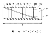
そこで、図1に示すように、MPEG(Moving Picture Experts Group)−2を用いたイントラスライス方式により、HD動画像データを符号化して伝送するようになされた画像処理装置が提案されている(例えば特許文献1参照)。 Therefore, as shown in FIG. 1, there has been proposed an image processing apparatus configured to encode and transmit HD moving image data by an intra slice method using MPEG (Moving Picture Experts Group) -2 (for example, Patent Document 1).
このMPEG−2を用いたイントラスライス方式では、ピクチャが、イントラ符号化されるIピクチャ領域I_MBと、前方向予測符号化されるPピクチャ領域P_MBとから構成される。イントラスライス方式では、1ピクチャごとに所定のMBライン数でなるIピクチャ領域(以下、これをリフレッシュラインと呼ぶ)RLを出現させる。このリフレッシュラインRLは、順次ずれて出現することにより、周期Tでピクチャの全てにおいて出現する。 In the intra slice method using MPEG-2, a picture is composed of an I picture area I_MB that is intra-coded and a P picture area P_MB that is forward-predictively coded. In the intra-slice method, an I picture area (hereinafter referred to as a refresh line) RL having a predetermined number of MB lines appears for each picture. The refresh lines RL appear in all the pictures with a period T by appearing sequentially shifted.
これにより、イントラスライス方式では、ピクチャごとの符号量を均一にすることができるため、HD動画像データを伝送してから表示装置に表示されるまでの遅延を小さくするようになされている。 As a result, in the intra slice method, the code amount for each picture can be made uniform, so that a delay from when HD moving image data is transmitted until it is displayed on a display device is reduced.
ところで近年、IEEE 802.11nによる伝送方式が普及していることから、IEEE 802.11nを用いてHD動画像データの無線伝送を行う方式が注目されている。 By the way, since a transmission method based on IEEE 802.11n has become widespread in recent years, a method for wirelessly transmitting HD moving image data using IEEE 802.11n has attracted attention.
しかしながら、IEEE 802.11nを用いる場合、伝送帯域としては100[Mbps]以下が主流となる。上述したMPEG−2を用いたイントラスライス方式は、圧縮効率が低く、ビットレートを100[Mbps]以下にすることが困難である。
However, when IEEE 802.11n is used, the transmission band is 100 [Mbps] or less. The intra slice method using MPEG-2 described above has low compression efficiency, and it is difficult to make the
そこで、イントラスライス方式をより圧縮効率の高いH.264/AVC(Advanced Video Coding)に適用することが望ましい。しかしながら、H.264/AVCでは、動き予測に1/4画素を生成すること、デブロックフィルタの使用が想定されていることなど、MPEG−2とはその構成が相違する。このため、イントラスライス方式をそのまま適用した場合、H.264/AVCとMPEG−2との相違により、エラーの伝搬を防止することができず、エラーからの復帰に時間を要してしまうという問題があった。 Therefore, the intra-slice method is H.264 with higher compression efficiency. It is desirable to apply to H.264 / AVC (Advanced Video Coding). However, H.C. H.264 / AVC has a different configuration from MPEG-2, such as generating 1/4 pixels for motion prediction and using a deblocking filter. Therefore, when the intra slice method is applied as it is, the Due to the difference between H.264 / AVC and MPEG-2, there is a problem that error propagation cannot be prevented and it takes time to recover from the error.
本発明は以上の点を考慮してなされたもので、復号時にエラーから復帰するまでの時間を短縮し得る画像処理装置及び画像処理方法を提案しようとするものである。 The present invention has been made in consideration of the above points, and an object of the present invention is to propose an image processing apparatus and an image processing method capable of shortening the time required to recover from an error during decoding.
かかる課題を解決するため本発明の画像処理装置においては、参照対象となる参照ピクチャにおける参照符号化単位に対し、整数精度の隣接画素を用いたフィルタ処理によって隣接画素に対応する整数精度未満の画素を生成し、復号されるときにエラーから復帰していない未復帰のマクロブロックを参照して生成される整数精度未満の画素を含有しないよう、参照符号化単位に対する探索範囲を設定する探索範囲設定部と、探索範囲設定部において設定された探索範囲で動きベクトルを検出し、動き予測処理を実行する動き予測部とを設けるようにした。 In order to solve such a problem, in the image processing apparatus of the present invention, a pixel of less than integer precision corresponding to an adjacent pixel by a filter process using an adjacent pixel of integer precision with respect to a reference coding unit in a reference picture to be referred to Search range setting that sets the search range for the reference coding unit so that it does not contain pixels with less than integer precision that are generated by referring to unreturned macroblocks that have not recovered from errors when decoded And a motion prediction unit that detects a motion vector in the search range set in the search range setting unit and executes a motion prediction process .
これにより、画像処理装置では、動き予測処理及びデブロックフィルタ処理に起因する復号時のエラー伝搬を防止することができる。 Thereby, the image processing apparatus can prevent error propagation at the time of decoding due to the motion prediction process and the deblocking filter process.
本発明の画像処理方法では、参照対象となる参照ピクチャにおける参照符号化単位に対し、整数精度の隣接画素を用いたフィルタ処理によって隣接画素に対応する整数精度未満の画素を生成し、復号されるときにエラーから復帰していない未復帰のマクロブロックを参照して生成される整数精度未満の画素を含有しないよう、参照符号化単位に対する探索範囲を設定する探索範囲設定ステップと、探索範囲設定ステップにおいて設定された探索範囲で動きベクトルを検出し、動き予測処理を実行する動き予測ステップとを設けるようにした。 In the image processing method of the present invention, a pixel of less than integer precision corresponding to an adjacent pixel is generated and decoded by a filtering process using an adjacent pixel of integer precision with respect to a reference coding unit in a reference picture to be referenced. A search range setting step for setting a search range for a reference coding unit so as not to include pixels with less than integer precision generated by referring to an unreturned macroblock that has not recovered from an error, and a search range setting step And a motion prediction step for detecting a motion vector in the search range set in step (b) and executing a motion prediction process .
これにより、画像処理方法では、動き予測処理及びデブロックフィルタ処理に起因する復号時のエラー伝搬を防止することができる。 Thereby, in the image processing method, it is possible to prevent error propagation at the time of decoding due to the motion prediction process and the deblocking filter process.
本発明によれば、動き予測処理及びデブロックフィルタ処理に起因する復号時のエラー伝搬を防止することができる。かくして本発明は、復号時にエラーから復帰するまでの時間を短縮し得る画像処理装置及び画像処理方法を実現できる。 ADVANTAGE OF THE INVENTION According to this invention, the error propagation at the time of the decoding resulting from a motion estimation process and a deblocking filter process can be prevented. Thus, the present invention can realize an image processing apparatus and an image processing method that can shorten the time required to recover from an error during decoding.
以下、図面について、本発明の一実施の形態を詳述する。なお、説明は以下の順序で行う。
1.第1の実施の形態(デブロックフィルタを用いないAVCイントラスライス方式)
2.第2の実施の形態(デブロックフィルタを用いたAVCイントラスライス方式)
3.第3の実施の形態(1マクロブロックごとにリフレッシュブロックが出現するランダムリフレッシュ方式)
4.第4の実施の形態(複数マクロブロックごとにリフレッシュブロックが出現するランダムリフレッシュ方式)
5.第5の実施の形態(ランダムリフレッシュ方式におけるデブロックフィルタの使用)
6.他の実施の形態
Hereinafter, an embodiment of the present invention will be described in detail with reference to the drawings. The description will be given in the following order.
1. First embodiment (AVC intra-slice method not using a deblocking filter)
2. Second Embodiment (AVC Intra Slice Method Using Deblock Filter)
3. Third Embodiment (Random refresh method in which a refresh block appears for each macroblock)
4). Fourth embodiment (random refresh method in which a refresh block appears for each of a plurality of macroblocks)
5. Fifth embodiment (use of deblocking filter in random refresh method)
6). Other embodiments
<1.第1の実施の形態>
[1−1.画像処理装置の構成]
図2おいて100は、全体として無線画像データ伝送システムを示している。この無線画像データ伝送システム100は、例えば地上デジタル放送などの放送信号を受信して表示する壁掛テレビでなり、画像処理装置1及び表示装置30を有している。
<1. First Embodiment>
[1-1. Configuration of image processing apparatus]
In FIG. 2,
画像処理装置1は、放送信号S1を受信し、得られる画像データをH.264/AVCに従って符号化し、ビットストリームS6を生成する。そして画像処理装置1は、ビットストリームS6及び音声データが符号化された符号化音声データS7を表示装置30に無線伝送する。表示装置30は、ビットストリームS6及び符号化音声データS7を復号して出力する。この結果、表示装置30は、地上デジタル放送などに基づく放送番組コンテンツをユーザに視聴させることができる。
The
デジタル放送受信部2は、例えばアンテナやインターネットなどのネットワークに接続されており、地上デジタル放送などの放送信号S1を受信する外部インターフェースでなる。この放送信号S1は、例えばMPEG(Moving Picture Experts Group)−2規格に従って符号化されている。
The
デジタル放送受信部2は、放送番組コンテンツを表す放送信号S1を受信すると、これを放送信号S2としてデジタルチューナ部3へ供給する。デジタルチューナ部3は、放送信号S2を復号し、画像データS4及び音声データS5をそれぞれ生成する。
When receiving the broadcast signal S1 representing the broadcast program content, the digital
デジタルチューナ部3は、画像データS4を画像符号化部4に供給し、音声データS5を音声符号化部5に供給する。画像符号化部4は、後述する画像符号化処理によりH.264/AVC(Advanced Video Coding)方式に従って画像データS4を符号化してビットストリームS6を生成し、これを送信部6に供給する。
The
音声符号化部5は、所定の符号化方式に従って音声データS5を符号化して音声符号データS7を生成し、これを送信部6に供給する。送信部6は、例えばIEEE 802.11nなどの無線伝送方式により、ビットストリームS6及び音声符号データS7を送信する。
The
この結果、表示装置30には、ビットストリームS6及び音声符号データS7が供給される。表示装置30は、無線受信部31によってビットストリームS6及び音声符号データS7を受信すると、これを復号部32に供給する。
As a result, the display device 30 is supplied with the bit stream S6 and the audio code data S7. When the
復号部32は、ビットストリームS6及び音声符号データS7を復号し、画像データS4及び音声データS5に対応する画像データS14及び音声データS15を生成し、表示部33及びスピーカ34にそれぞれ供給する。この結果、表示部33には、画像データS14に基づく画像が表示される。また、スピーカ34からは、音声データS15に基づく音声が出力される。
The
このように、画像処理装置1及び表示装置30は、符号化された放送信号を無線で送受するようになされている。
Thus, the
[1−2.画像符号化部の構成]
図3に示すように、画像符号化部4は、デジタルチューナ部3から画像データS4が供給されると、画像データS4をバッファ8へ供給する。
[1-2. Configuration of image encoding unit]
As shown in FIG. 3, the
バッファ8は、画像データS4をピクチャヘッダ生成部9に供給する。ピクチャヘッダ生成部9は、ピクチャヘッダを生成して画像データS4に付加し、イントラマクロブロック判定部10、並びに動き予測・補償部14又はイントラ予測部15にそれぞれ供給する。このときピクチャヘッダ生成部9は、constraind_intra_pred_flag(詳しくは後述する)などのフラグを付加する。
The
イントラマクロブロック判定部10は、マクロブロックごとに、Iマクロブロックとしてイントラ符号化するか又はPマクロブロックとしてインター符号化するかを決定する。イントラマクロブロック判定部10は、決定結果をスライス分割判定部11、スライスヘッダ生成部12及びスイッチ28に供給すると共に、画像データS4を演算器13に供給する。
The intra macroblock
スライス分割判定部11は、イントラマクロブロック判定部10の決定結果などに基づいて、スライスを分割するか否かを判定し、判定結果をスライスヘッダ生成部12に供給する。
The slice division determination unit 11 determines whether to divide the slice based on the determination result of the intra macroblock
スライスヘッダ生成部12は、スライスヘッダを生成して画像データS4に付加し、これを演算器13に供給する。
The slice
演算器13は、画像データS4をインター符号化すべき場合には、動き予測・補償部14から供給される予測値L5を画像データS4から減算し、これを差分データD1として直交変換部17に供給する。演算器13は、画像データS4をイントラ符号化すべき場合には、イントラ予測部15から供給される予測値L5を画像データS4から減算し、これを差分データD1として直交変換部17に供給する。
When the image data S4 is to be inter-coded, the
直交変換部17は、DCT(Discrete Cosine Transform)変換及びカルーネン・レーベ変換などの直交変換処理により、差分データD1を直交変換し、直交変換係数D2を量子化部18に供給する。
The orthogonal transformation unit 17 performs orthogonal transformation on the difference data D1 by orthogonal transformation processing such as DCT (Discrete Cosine Transform) transformation and Karhunen-Loeve transformation, and supplies the orthogonal transformation coefficient D2 to the
量子化部18は、レート制御部19の制御により決定された量子化パラメータQPを用いて直交変換係数D2を量子化し、量子化係数D3を逆量子化部23及び可逆符号化部20に供給する。可逆符号化部20は、CAVLC(Context-based Adaptive Variable Length Code)及びCABAC(Context Adaptive Binary Arithmetic Coding)などのエントロピー符号化方式に従って量子化係数D3を可逆符号化し、可逆符号化データD5を蓄積バッファ21に供給する。
The
また、可逆符号化部20は、イントラ符号化及びインター符号化に関する情報を動き予測・補償部14及びイントラ予測部15から取得しこれらの情報を可逆符号化データD5のヘッダ情報に設定する。
In addition, the
蓄積バッファ21は、可逆符号化データD5を蓄積すると共に、当該可逆符号化データD5を所定の伝送速度でビットストリームS6として出力する。レート制御部19は、蓄積バッファ21を監視し、可逆符号化データD5の発生符号量が所定の制御単位(例えばフレームやGOPなど)ごとに一定の符号量に近づくよう、量子化パラメータQPを決定する。
The
逆量子化部23は、量子化係数D3を逆量子化して再生直交変換係数L1を生成し、これを逆直交変換部24に供給する。逆直交変換部24は、再生直交変換係数L1を逆直交変換して再生差分データL2を生成する。逆直交変換部24は、同時に供給される参照対象ブロックの画像データと再生差分データL2とを加算してローカルデコード画像L3を生成し、これをデブロックフィルタ26に供給する。
The
デブロックフィルタ26は、処理対象ブロックに対してデブロックフィルタ処理を実行し、これをフレームメモリ27に供給する。この結果、フレームメモリ27には、デブロックフィルタ処理されたローカルデコード画像L4が記憶される。
The
フレームメモリ27は、デブロックフィルタ処理されたローカルデコード画像L4のうち、参照対象ブロックに対応するローカルデコード画像L4を、動き予測・補償部14又はイントラ予測部15に対して供給する。このとき、イントラマクロブロック判定部10の判定結果に応じてスイッチ28が切換えられる。
The
動き予測・補償部14は、ローカルデコード画像L4を参照して画像データS4に対する動き予測により処理対象ブロックの予測値L5を生成し、演算器13に供給する。イントラ予測部15は、ローカルデコード画像L4を参照して画像データS4に対するイントラ予測により処理対象ブロックの予測値L5を生成し、演算器13に供給する。
The motion prediction /
このように、画像符号化部4は、画像データS4を符号化してビットストリームS6を生成するようになされている。
As described above, the
[1−3.AVC特有のエラーの伝搬要因]
以下、AVC特有のエラー伝搬要因として、第1〜第3の伝搬要因について順次説明する。第1の伝搬要因は、動きベクトルの検出時における探索範囲である。
[1-3. AVC-specific error propagation factors]
Hereinafter, the first to third propagation factors will be sequentially described as error propagation factors specific to AVC. The first propagation factor is a search range at the time of detecting a motion vector.
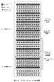
図4に示すように、MPEG−2によるイントラスライス方式では、ピクチャごとにリフレッシュラインRLが1ライン分ずつ変動するように、符号化しておく。このリフレッシュラインRLは、1マクロブロックごとのラインでも良く、また複数のマクロブロックごとのラインであっても良い。以下、リフレッシュラインRLの出現するライン単位を、符号化ライン単位と呼ぶ。また、マクロブロックがx方向(水平方向)に並ぶラインをマクロブロックラインと呼ぶ。1マクロブロックラインとは、1つのマクロブロックが並ぶラインのことである。 As shown in FIG. 4, in the intra-slice method according to MPEG-2, encoding is performed so that the refresh line RL varies by one line for each picture. The refresh line RL may be a line for each macro block or a line for each of a plurality of macro blocks. Hereinafter, the line unit in which the refresh line RL appears is referred to as an encoded line unit. A line in which macroblocks are arranged in the x direction (horizontal direction) is called a macroblock line. One macroblock line is a line in which one macroblock is arranged.
これにより、仮に復号時において1枚のピクチャにエラーが生じた場合、図4(A)に示すように、次にピクチャにおいてリフレッシュラインRLのみが復帰し、残りのインター符号化領域は未復帰ラインURとなる。 As a result, if an error occurs in one picture during decoding, only the refresh line RL is restored next in the picture as shown in FIG. 4A, and the remaining inter-coded areas are not restored lines. It becomes UR.
イントラスライス方式では、直前のピクチャにおけるリフレッシュラインRLを探索範囲として動きベクトルを検出することにより符号化を実行している。復号時において、図4(B)に示すように次のピクチャは、リフレッシュラインRLのみを参照して復号化することができ、未復帰ラインURを参照せずに済むため、参照する直前のピクチャのリフレッシュラインRLに対応する部分を復帰済ラインARとして復帰させることが可能となる。 In the intra slice method, encoding is performed by detecting a motion vector using the refresh line RL in the immediately preceding picture as a search range. At the time of decoding, as shown in FIG. 4B, the next picture can be decoded by referring to only the refresh line RL, and it is not necessary to refer to the unreturned line UR. The portion corresponding to the refresh line RL can be restored as the restored line AR.
MPEG−2のイントラスライス方式に従って画像データを復号化する従来の符号化装置は、エラーが生じたか否かを認識することができない。従って、MPEG−2のイントラ符号化方式に従って符号化を行う従来の符号化装置は、動きベクトルの探索範囲を常に符号化ライン単位の範囲内になるように設定している。この結果、従来の復号化装置は、動きベクトルの探索範囲を常に符号化ライン単位の範囲内にすることができる。 A conventional encoding device that decodes image data in accordance with the MPEG-2 intra slice method cannot recognize whether an error has occurred. Therefore, a conventional coding apparatus that performs coding in accordance with the MPEG-2 intra coding method sets the motion vector search range to be always within the range of the coding line unit. As a result, the conventional decoding device can always make the motion vector search range within the range of the coding line unit.
図5に示すように、復帰済ラインARは、リフレッシュラインRLの出現に伴って徐々に増大していく。周期Tのピクチャだけ復号が終了すると、全ての位置においてリフレッシュラインRLが出現し終えるため、ピクチャ内の全ての位置において画像を復帰させることができる。 As shown in FIG. 5, the restored line AR gradually increases as the refresh line RL appears. When the decoding of only the picture of the period T is completed, the refresh line RL finishes appearing at all positions, so that the image can be restored at all positions within the picture.
ところで、MPEG−2では、1/2画素精度で動きベクトルの検出をしている。このため、従来の符号化装置は、1/2画素を生成するために、2TAPのFIR(Finite Impulse Response Filter)フィルタを用いる。この2TAPのFIRフィルタは、隣接画素を参照しないため、リフレッシュラインRL及び未復帰ラインUR間でのエラーの伝搬が生じない。 By the way, in MPEG-2, a motion vector is detected with 1/2 pixel accuracy. For this reason, the conventional encoding device uses a 2TAP FIR (Finite Impulse Response Filter) filter to generate ½ pixel. Since this 2TAP FIR filter does not refer to adjacent pixels, error propagation does not occur between the refresh line RL and the unrecovered line UR.
これに対して、H.264/AVCでは、1/4画素精度で動きベクトルの検出をしている。このため、H.264/AVCに従って符号化処理を行う符号化装置は、1/2画素及び1/4画素を生成するために、6TAPのFIRフィルタを用いる。この6TAPのFIRフィルタは、隣接する6画素を参照する。 On the other hand, H.H. In H.264 / AVC, motion vectors are detected with 1/4 pixel accuracy. For this reason, H.C. An encoding apparatus that performs encoding processing according to H.264 / AVC uses a 6TAP FIR filter to generate 1/2 pixel and 1/4 pixel. This 6TAP FIR filter refers to 6 adjacent pixels.
このため、図6に示すように、リフレッシュラインRL及び未復帰ラインURの境界(以下、これをリフレッシュ境界BDと呼ぶ)から3画素より外側(未復帰ラインUR側)に位置する1/2画素及び1/4画素(縦線で示す)は、未復帰ラインURを参照することになる。このリフレッシュ境界BDは、リフレッシュラインRL及び未復帰ラインURの境界となり得る境界(すなわち符号化ライン単位の境界)を指す。なお図6では、画素間においてy方向にのみ1/2画素及び1/4画素が生成されているが、実際にはx方向にも1/2画素及び1/4画素が生成される。 For this reason, as shown in FIG. 6, ½ pixel located outside the three pixels from the boundary of the refresh line RL and the non-returned line UR (hereinafter referred to as the refresh boundary BD) (on the non-returned line UR side). And 1/4 pixels (indicated by vertical lines) refer to the unreturned line UR. The refresh boundary BD indicates a boundary that can be a boundary between the refresh line RL and the unrecovered line UR (that is, a boundary in units of encoded lines). In FIG. 6, ½ pixel and ¼ pixel are generated only in the y direction between the pixels, but actually ½ pixel and ¼ pixel are also generated in the x direction.
この結果、リフレッシュラインRLの内部であっても、リフレッシュ境界BDから3画素より外側に位置する1/2画素及び1/4画素には、エラーが伝搬してしまう。以下、リフレッシュラインRLにおいてエラーが伝搬してしまうこれらの画素を、エラー伝搬画素と呼ぶ。従って、符号化時に符号化ライン単位で動きベクトルの探索範囲を設定すると、復号時にエラー伝搬画素を参照してしまう可能性があり、復帰済ラインARにおいてエラーを伝搬させることになる。これが第1のエラー伝搬要因である。 As a result, even within the refresh line RL, an error propagates to the ½ pixel and ¼ pixel located outside the three pixels from the refresh boundary BD. Hereinafter, these pixels in which an error propagates in the refresh line RL are referred to as error propagation pixels. Accordingly, if a motion vector search range is set in units of encoded lines during encoding, there is a possibility that error propagation pixels will be referred to during decoding, and errors will be propagated in the restored line AR. This is the first error propagation factor.
H.264/AVCでは、イントラ符号化に、画面内予測符号化を用いる。第2のエラー伝搬要因は、画面内予測符号化に起因するものである。 H. In H.264 / AVC, intra prediction encoding is used for intra encoding. The second error propagation factor is due to intra prediction encoding.
図7に示すように、この画面内予測符号化では、符号化対象となるIマクロブロックに隣接し、上又は左隣若しくはその両方の画素を参照する。Iマクロブロックがその上又は左をリフレッシュ境界BDに隣接させて位置する場合、未復帰ラインURを参照することになり、エラーを伝搬させることになる。これが第2のエラー伝搬要因である。 As shown in FIG. 7, in this intra prediction encoding, reference is made to the pixels adjacent to the I macroblock to be encoded and the upper and / or left adjacent pixels. If the I macroblock is located above or on the left adjacent to the refresh boundary BD, the unreturned line UR will be referred to and an error will be propagated. This is the second error propagation factor.
H.264/AVCでは、ブロックノイズを抑制するため、デブロックフィルタを使用する。第3のエラー伝搬要因は、デブロックフィルタに起因するものである。 H. In H.264 / AVC, a deblocking filter is used to suppress block noise. The third error propagation factor is due to the deblocking filter.
デブロックフィルタは、隣接する2画素ずつ(4画素)を参照することにより、デブロックフィルタ処理を実行する。従って、図8に示すように、リフレッシュラインRLにおけるリフレッシュ境界BDから2画素では、エラーを伝搬させてしまう。これが、第3のエラー伝搬要因である。 The deblocking filter performs the deblocking filter process by referring to every two adjacent pixels (four pixels). Therefore, as shown in FIG. 8, an error is propagated in two pixels from the refresh boundary BD in the refresh line RL. This is the third error propagation factor.
本発明では、これら第1〜第3のエラー伝搬要因を回避し、エラーの伝搬を防止し得るようになされている。 In the present invention, these first to third error propagation factors can be avoided and error propagation can be prevented.
[1−4.エラー伝搬の回避]
[1−4−1.第1のエラー伝搬要因の回避]
図6を用いて上述したように、画像符号化部4は、仮に符号化ライン単位で動きベクトルの探索範囲を設定すると、エラーの伝搬を生じてしまう。そこで画像符号化部4は、エラーの伝搬が生じないよう探索範囲を設定する。
[1-4. Avoiding error propagation]
[1-4-1. Avoiding the first error propagation factor]
As described above with reference to FIG. 6, if the
符号化ライン単位が1マクロブロックラインであった場合、16×16画素の検索ブロックがy方向に1/4画素でも移動すると、リフレッシュラインRLからはみ出ることになるため、未復帰ラインURを参照することになる。この場合、探索範囲設定部16は、動きベクトルの探索範囲をx方向にのみ設定する。
When the encoding line unit is one macroblock line, if a search block of 16 × 16 pixels moves even by 1/4 pixel in the y direction, it will protrude from the refresh line RL. It will be. In this case, the search
具体的に、探索範囲設定部16は、ピクチャヘッダから符号化単位ラインにおけるマクロブロックライン数を確認する。探索範囲設定部16は、符号化ライン単位が1マクロブロックラインであった場合、y方向の動きベクトルMVy=0とし、x方向の探索範囲を制限無し(x方向に規格上許容される最大値)に設定し、この探索範囲に該当する参照対象ブロックを動き予測・補償部14に供給する。動き予測・補償部14は、この探索範囲内において整数精度で動きベクトルを検出し、当該動きベクトルを探索範囲設定部16に供給する。
Specifically, the search
次に、探索範囲設定部16は、整数精度で検出された動きベクトルの周辺画素について、6TAPのFIRフィルタを用いて例えば図9に示すように、x方向にのみ1/2画素及び1/4画素を生成し、これを動き予測・補償部14に供給する。動き予測・補償部14は、x方向について1/4精度で動きベクトルを検出する。
Next, the search
これにより、画像符号化部4は、探索範囲にy方向の1/2画素及び1/4画素を含有させないため、リフレッシュ境界BDに隣接する2画素分の1/2画素及び1/4画素を含有させずに済む。この結果、画像符号化部4は、復号時においてエラー伝搬画素を参照させずに済むため、復帰ラインARにおけるエラーの伝搬を防止することができ、第1のエラー伝搬要因を回避することができる。
As a result, the
また、探索範囲設定部16は、符号化ライン単位が2マクロブロックライン以上であった場合、復号時においてエラー伝搬画素を参照しないように動きベクトルの探索範囲を設定する。
Also, the search
ここで、画像符号化部4は、ピクチャ間においてリフレッシュラインRLを下側にずらすように変動させてエラーから復帰させる。このため、エラー伝搬画素画が発生するのは、未復帰ラインURと隣接するリフレッシュラインRLの下側のみとなる。そこで、画像符号化部4は、リフレッシュラインRLの下側について、エラー伝搬画素を参照しないように探索範囲を設定する。
Here, the
具体的に、探索範囲設定部16は、探索範囲を符号化単位ラインの範囲内に設定し、この探索範囲に該当する画像を動き予測・補償部14に供給する。動き予測・補償部14は、この探索範囲内において整数精度で動きベクトルを検出し、当該動きベクトルを探索範囲設定部16に供給する。
Specifically, the search
探索範囲設定部16は、整数精度で検出された動きベクトルの周辺画素について、6TAPのFIRフィルタを用いて例えば図10に示すように、1/2画素及び1/4画素を生成する。このとき、探索範囲設定部16は、リフレッシュ境界BDから3画素よりも外側の領域について、y方向に1/2画素及び1/4画素を生成しないようにして参照対象ブロックを生成し、これを動き予測・補償部14に供給する。
For example, as shown in FIG. 10, the search
動き予測・補償部14は、x及びy方向について原則的に1/4精度で動きベクトルを検出する。動き予測・補償部14は、リフレッシュ境界BDから3画素よりも外側については、y方向において1/2画素及び1/4画素が存在しないため、整数精度で動きベクトルを検出することになる。
The motion prediction /
これにより、画像符号化部4は、復号時にリフレッシュ境界BDから3画素よりも外側についての1/2画素及び1/4画素を参照させないようにでき、エラー伝搬画素の参照によるエラーの伝搬を防止することができる。
As a result, the
このように、画像符号化部4は、動きベクトルの検出時において、エラー伝搬画素に対応する画素(リフレッシュ境界BDから3画素よりも外側についての1/2画素及び1/4画素)を参照しないようにした。これにより、復号部32は、インター符号化により符号化された復帰済ラインARを復号する際に、エラー伝搬画素を参照せずに復号できるため、エラー伝搬を防止することができ、第1のエラー伝搬要因を回避できる。
As described above, the
[1−4−2.第2のエラー伝搬要因の回避]
画像符号化部4は、リフレッシュラインRLにおける画面内予測符号化において、当該リフレッシュラインRL以外の画素を参照しないようにすれば、未復帰ラインURからのエラーの伝搬を防止することができる。
[1-4-2. Avoiding second error propagation factor]
If the
ところで、H.264/AVCでは、画面内予測符号化する際、スライスを跨ぐ画素を参照しない。言い換えると、リフレッシュラインRLをスライスの先頭にすることにより、未復帰ラインURを参照せずに画面内符号化が実行される。これにより、復号部32は、リフレッシュラインRLを復号する際に、未復帰ラインURを参照せずに復号できるため、エラー伝搬を防止することができる。
H. In H.264 / AVC, pixels that cross slices are not referred to when intra prediction encoding is performed. In other words, by setting the refresh line RL at the head of the slice, intra-frame coding is executed without referring to the non-returned line UR. Thereby, when decoding the refresh line RL, the
具体的に、ピクチャヘッダ生成部9(図3)は、ピクチャヘッダにおいてリフレッシュラインRLの先頭をスライス先頭にするか否かを表すフラグを「true」に設定する。イントラマクロブロック判定部10は、処理対象となるマクロブロックがイントラ符号化すべきIマクロブロックか、インター符号化すべきPマクロブロックかを判別する。
Specifically, the picture header generation unit 9 (FIG. 3) sets a “true” flag indicating whether or not the head of the refresh line RL is set to the head of the slice in the picture header. The intra macroblock
イントラマクロブロック判定部10は、1ライン分ずつ変動するリフレッシュラインRLに該当するマクロブロックを強制的にイントラ符号化される強制イントラマクロブロックとし、イントラ符号化することを決定する。なお以下、リフレッシュラインRLに属するマクロブロックを、リフレッシュマクロブロックと呼ぶ。また、リフレッシュラインRL以外のマクロブロックが構成するラインをインターマクロブロックラインと呼び、インターマクロブロックラインに属するマクロブロックを、他マクロブロックと呼ぶ。
The intra macroblock
一方、イントラマクロブロック判定部10は、リフレッシュラインRL以外のマクロブロック(すなわちイントラマクロブロックラインに属するマクロブロック)について、Iマクロブロックとしてイントラ符号化するか又はPマクロブロックとして前方向インター符号化するかを決定する。
On the other hand, the intra macroblock
イントラマクロブロック判定部10は、Iマクロブロック及びPマクロブロックの発生符号量を予測し、符号化効率の良い符号化方式を判定する。この判定結果は、スライス分割判定部11に供給される。
The intra macroblock
スライス分割判定部11は、リフレッシュラインRLの先頭をスライス先頭にするフラグが「true」であり、かつ現在のマクロブロックが強制イントラマクロブロックであり、さらにリフレッシュラインRLの先頭である場合、スライス分割を実行すべきと判定する。 The slice division determination unit 11 performs slice division when the flag that sets the beginning of the refresh line RL to the beginning of the slice is “true”, the current macroblock is a forced intra macroblock, and further, the head of the refresh line RL. Is determined to be executed.
また、スライス分割判定部11は、ピクチャを複数のスライスに分割することが予め定められている場合、処理対象のマクロブロックの位置に応じて、スライス分割を実行すべきか否かを判定する。これらの判定結果は、スライスヘッダ生成部12に供給される。
In addition, when it is predetermined that the picture is divided into a plurality of slices, the slice division determination unit 11 determines whether or not to perform the slice division according to the position of the macroblock to be processed. These determination results are supplied to the slice
スライスヘッダ生成部12は、スライスヘッダを生成し、現在のマクロブロックの先頭に当該スライスヘッダを付加することにより、新規スライスを生成する。イントラ予測部15は、スライス先頭のマクロブロックについて、例えば中間の画素値(「0〜255」の画素値であれば、「128」)を参照することにより、インターマクロブロックラインを参照することなくイントラ符号化を実行する。
The slice
これにより、画像符号化部4は、リフレッシュラインRLの先頭をスライス先頭にすることができる。これにより、復号部32は、リフレッシュラインRLの復号時に未復帰ラインURを参照せずに済むため、エラーの伝搬を防止することができる。
Accordingly, the
このように、画像符号化部4は、リフレッシュラインRLをスライスの先頭にすることにより、リフレッシュラインRLにおいてインターマクロブロックラインを参照しない。このため、復号部32は、リフレッシュラインRLを復号する際に、未復帰ラインURを参照せずに済むため、エラーの伝搬を防止することができ、第2のエラー伝搬要因を回避できる。
As described above, the
また、H.264/AVCでは、constrained_intra_pred_flagというフラグが用意されている。このフラグを「1」にすることにより、イントラ符号においてインター符号化された画素を参照しないことを規定することができる。ただし、このフラグが「1」に設定されていると、強制イントラマクロブロック以外のIマクロブロックでもインター符号化された画素を参照しないため、符号化効率が低下するという欠点を有する。 H. In H.264 / AVC, a flag called constrained_intra_pred_flag is prepared. By setting this flag to “1”, it is possible to specify that an inter-coded pixel in the intra code is not referred to. However, if this flag is set to “1”, the inter-encoded pixels are not referred to even in I macroblocks other than the forced intra macroblock, so that there is a disadvantage that the encoding efficiency is lowered.
具体的に、画像符号化部4のピクチャヘッダ生成部9は、ピクチャヘッダにおけるPPS(Picture Parameter set)におけるconstrained_intra_pred_flag=1とする。このフラグが「1」であることは、イントラ符号においてインター符号化された画素を参照しないことを表している。
Specifically, the picture
イントラ予測部15は、constrained_intra_pred_flag=1であることを確認すると、イントラ符号化された画素のみを参照して画面内予測処理を実行する。この結果、復号部32は、イントラ符号化された画素のみを参照して画像データS4を復号することができるため、未復帰ラインURからのエラーの伝搬を防止できる。
When the
このように、画像符号化部4は、constrained_intra_pred_flag=1とすることにより、未復帰ラインURからのエラーの伝搬を防止し、第2のエラー伝搬要因を回避し得るようになされている。
As described above, the
[1−4−3.第3のエラー伝搬要因の回避]
上述したように、デブロックフィルタを用いると、リフレッシュラインRLを復号する際、リフレッシュ境界BDから2画素(以下、これを境界画素と呼ぶ)に未復帰ラインURの画素が影響を与えるため、当該境界画素が壊れてしまう。従って、画像符号化部4は、デブロックフィルタを使用しないようにする。
[1-4-3. Avoidance of third error propagation factor]
As described above, when the deblocking filter is used, when the refresh line RL is decoded, the pixels of the unrecovered line UR affect two pixels (hereinafter referred to as boundary pixels) from the refresh boundary BD. The boundary pixel is broken. Therefore, the
具体的に、画像符号化部4のスライスヘッダ生成部12は、disable_deblocking_filter_idc=1とする。デブロックフィルタ26は、disable_deblocking_filter_idcを確認し、このフラグが「1」となっている場合には、当該スライスについて、デブロックフィルタ処理を実行しない。
Specifically, the slice
このため、復号部32は、リフレッシュラインRLを復号する際に、リフレッシュラインRLにデブロックフィルタ処理を実行せずに済むため、エラーの伝搬を防止することができる。
For this reason, when the
このように、画像符号化部4は、デブロックフィルタを用いないことにより、未復帰ラインURの画素の影響によってリフレッシュラインRLの境界画素が壊れることを防止でき、第3のエラー伝搬要因を回避できる。
As described above, the
[1−5.処理手順]
画像符号化部4は、符号化処理を開始すると、ステップSP1へ移り、処理対象となるマクロブロックがピクチャの先頭か否かを判別し、肯定結果が得られるとステップSP2へ移る一方、否定結果が得られた場合、ステップSP3へ移る。
[1-5. Processing procedure]
When starting the encoding process, the
ステップSP2において、画像符号化部4は、マクロブロックの先頭にピクチャヘッダを付加すると、次のステップSP3へ移る。このとき画像符号化部4は、constraind_intra_pred_flagを付加する。
In step SP2, the
ステップSP3において、画像符号化部4は、サブルーチンSRT11へ移り、マクロブロック判定処理を実行する。画像符号化部4は、マクロブロック判定処理として、処理対象となるマクロブロックをインター符号化すべきかイントラ符号化すべきかを判定すると、次のステップSP4へ移る。
In step SP3, the
ステップSP4において、画像符号化部4は、サブルーチンSRT12又はSRT22へ移り、スライス分割判定処理を実行する。画像符号化部4は、スライス分割判定処理として、スライス分割を実行するか否かを判定すると、次のステップSP5へ移る。
In step SP4, the
ステップSP5において、画像符号化部4は、処理対象となるマクロブロックがイントラ符号化すべきIマクロブロック(強制イントラマクロブロック及びイントラマクロブロック)であるか否かについて判別する。
In step SP5, the
ここで肯定結果が得られると、画像符号化部4は、画面内予測処理を実行すべきであるため、次のステップSP6へ移る。ステップSP6において、画像符号化部4は、リフレッシュマクロブロックにおいて、インター符号化されたPマクロブロックを参照しないように画面内予測処理を実行し、差分データD1を生成すると、次のステップSP9へ移る。
If an affirmative result is obtained here, the
これに対してステップSP5において否定結果が得られると、画像符号化部4は、動き予測処理を実行すべきであるため、次のステップSP7へ移る。
On the other hand, if a negative result is obtained in step SP5, the
ステップSP7において、画像符号化部4は、サブルーチンSRT13又は23へ移り、探索範囲判定処理を実行する。画像符号化部4は、探索範囲判定処理として、リフレッシュラインRLの下側について、エラー伝搬画素(当該リフレッシュラインRLにおけるリフレッシュ境界BDから3画素よりも外側の1/2画素及び1/4画素)を参照しないよう探索範囲を設定すると、次のステップSP8へ移る。
In step SP7, the
ステップSP8において、画像符号化部4は、ステップSP7において設定された探索範囲において動きベクトルを検出し、動き予測処理を実行し、差分データD1を生成すると、次のステップSP9へ移る。
In step SP8, the
ステップSP9において、画像符号化部4は、差分データD1に対し、直交変換処理及び量子化処理を実行し、量子化係数D3を生成すると、次のステップSP10及びSP11へ移り、同時並行して当該ステップSP10及びSP11を実行する。ステップSP10において、画像符号化部4は、量子化係数D3に対し、可逆符号化処理を実行し、可逆符号化データD5を生成すると、これをビットストリームS6として送信部6に供給し、符号化処理手順RT1を終了する。
In step SP9, the
ステップSP11において、画像符号化部4は、逆量子化処理、逆直交変換処理を実行し、ローカルデコード画像L3を生成すると、次のステップSP12へ移る。
In step SP11, when the
ステップSP12において、画像符号化部4は、disable_deblocking_filter_idcを確認し、デブロックフィルタ処理を実行すべきか否かを判別する。
In step SP12, the
ここで肯定結果が得られた場合、画像符号化部4は、ステップSP13へ移り、デブロックフィルタ処理を実行すると、終了ステップへ移って符号化処理手順RT1を終了する。
If a positive result is obtained here, the
これに対してステップSP12において否定結果が得られた場合、画像符号化部4は、終了ステップへ移って符号化処理手順RT1を終了する。
On the other hand, when a negative result is obtained in step SP12, the
画像符号化部4は、符号化処理手順RT1のステップSP3からサブルーチンSRT11(図12)のステップSP21へ移る。
The
ステップSP21において、画像符号化部4は、マクロブロックが供給されると、ピクチャごとにマクロブロックの数をカウントするMBカウンタ及びスライスごとにマクロブロックの数をカウントするSMBカウンタを「+1」し、次のステップSP22へ移る。ステップSP22において、画像符号化部4は、処理対象となる現在のマクロブロックがリフレッシュマクロブロックか否かを判別する。
In step SP21, when a macroblock is supplied, the
ここで肯定結果が得られた場合、このことは、処理対象のマクロブロックがリフレッシュラインRLに属していることを表している。このとき、画像符号化部4は、ステップSP23へ移り、処理対象のマクロブロックを強制イントラマクロブロックとしてイントラ符号化することを選択し、次のステップSP25へ移る。
If a positive result is obtained here, this indicates that the macro block to be processed belongs to the refresh line RL. At this time, the
これに対してステップSP22において否定結果が得られた場合、このことは処理対象のマクロブロックがインターマクロブロックラインに属していることを表している。このとき、画像符号化部4は、次のステップSP24へ移る。
On the other hand, if a negative result is obtained in step SP22, this indicates that the macro block to be processed belongs to the inter macro block line. At this time, the
ステップSP24において、画像符号化部4は、処理対象のマクロブロックのインター符号化及びイントラ符号化による発生符号量を予測する。画像符号化部4は、符号化効率の良い方の符号化方式を実際に処理対象のマクロブロックを符号化する符号化方式として選択すると、次のステップSP25へ移る。
In step SP24, the
ステップSP25において、画像符号化部4は、処理対象のマクロブロックがピクチャにおける最後のマクロブロックか否かについて判別する。ここで否定結果が得られた場合、画像符号化部4は、ステップSP21へ戻り、ピクチャ内の全てのマクロブロックに対する処理が終了するまで、ステップSP21〜SP25までの処理を継続する。
In step SP25, the
これに対して、ステップSP25において肯定結果が得られた場合、画像符号化部4は、次のステップSP26へ移る。ステップSP26において、画像符号化部4は、MBカウンタを「0」にリセットし、次のステップSP27へ移る。
On the other hand, when a positive result is obtained in step SP25, the
ステップSP27において、画像符号化部4は、ピクチャの数をカウントするピクチャカウンタを「+1」すると、次のステップSP28へ移る。
In step SP27, the
ステップSP28において、画像符号化部4は、全てのピクチャに対する処理を終了したか否かについて判別し、否定結果が得られると、ステップSP21へもどり、全てのピクチャに対する処理を終了するまで、ステップSP21〜SP28の処理を継続する。
In step SP28, the
これに対して、ステップSP28において肯定結果が得られると、画像符号化部4は、符号化処理手順RT1(図11)のステップSP4へ移る。
On the other hand, if a positive result is obtained in step SP28, the
符号化処理手順RT1のステップSP4において、画像符号化部4は、スライス分割判定処理を表すサブルーチンSRT12(図13)のステップSP41へ移る。
In step SP4 of the encoding processing procedure RT1, the
ステップSP41において、画像符号化部4は、処理対象のマクロブロックに関し、以下の3つの条件を全て満たすか否かについて判別する。
1)リフレッシュラインRLの先頭をスライス先頭にするフラグが「true」である 2)処理対象のマクロブロックが強制イントラマクロブロックである
3)リフレッシュラインRLの先頭である
In step SP41, the
1) The flag that sets the head of the refresh line RL to the head of the slice is “true” 2) The macro block to be processed is a forced intra macro block 3) The head of the refresh line RL
ここで肯定結果が得られた場合、このことは、リフレッシュラインRLの先頭をスライス先頭にすべきであり、かつ現在のマクロブロックがリフレッシュラインRLの先頭であることを表している。このとき、画像符号化部4は、次のステップSP42へ移る。
If a positive result is obtained here, this indicates that the head of the refresh line RL should be the head of the slice, and the current macroblock is the head of the refresh line RL. At this time, the
これに対して、ステップSP41において否定結果が得られた場合、このことはリフレッシュラインRLの先頭をスライス先頭にすべきでないか、又は処理対象のマクロブロックがリフレッシュラインRLの先頭でないことを表している。このとき、画像符号化部4は、次のステップSP43へ移る。
On the other hand, if a negative result is obtained in step SP41, this indicates that the head of the refresh line RL should not be the head of the slice, or that the macro block to be processed is not the head of the refresh line RL. Yes. At this time, the
ステップSP43において、画像符号化部4は、処理対象のマクロブロックに関し、以下の2つの条件を全て満たすか否かについて判別する。
1)スライス分割をするか否かを決定するフラグが「true」である
2)スライスごとのMBの数をカウントするSMBカウンタがスライス分割閾値以上である
In step SP43, the
1) The flag that determines whether or not to divide the slice is “true”. 2) The SMB counter that counts the number of MBs per slice is equal to or greater than the slice division threshold.
ここで肯定結果が得られた場合、このことは、ピクチャを複数のスライスに分割することが予め定められており、現在のMBカウンタの値(すなわちマクロブロックの位置)から、スライス分割すべきであることを表している。このとき、画像符号化部4は、次のステップSP42へ移る。
If a positive result is obtained here, this means that the picture is predetermined to be divided into a plurality of slices, and the slice value should be divided from the current MB counter value (ie, the position of the macroblock). It represents something. At this time, the
ステップSP42において、画像符号化部4は、処理対象のマクロブロックから新規スライスとなるようスライス分割を実行すると共に、SMBカウンタをリセットする。このとき、画像符号化部4は、disable_deblocking_filter_idcを設定する。そして、画像符号化部4は、符号化処理手順RT1(図11)のステップSP5へ移る。
In step SP42, the
これに対して、ステップSP43において、否定結果が得られた場合、このことは、ピクチャを複数のスライスに分割する必要がない、又は現在のSMBカウンタの値(すなわちマクロブロックの位置)から、スライス分割すべきでないことを表している。このとき、画像符号化部4は、次のステップSP44へ移る。
On the other hand, if a negative result is obtained in step SP43, this means that it is not necessary to divide the picture into a plurality of slices, or from the current SMB counter value (that is, the position of the macroblock) Indicates that it should not be divided. At this time, the
ステップSP44において、画像符号化部4は、スライス分割をすることなく、符号化処理手順RT1(図11)のステップSP5へ移る。
In step SP44, the
符号化処理手順RT1(図11)のステップSP7において、画像符号化部4は、サブルーチンSRT13(図14)のステップSP51へ移り、リフレッシュラインRLのマクロブロックライン数が2以上であるか否かについて判別する。
In step SP7 of the encoding processing procedure RT1 (FIG. 11), the
ここで肯定結果が得られた場合、画像符号化部4は、次のステップSP52へ移る。ステップSP52において、画像符号化部4は、復号時にエラー伝搬画素を参照しないように、リフレッシュラインRLの上側について、リフレッシュ境界BDから3画素より外側の1/2画素及び1/4画素を除く符号化ライン単位をy方向の動きベクトルMVyの探索範囲に設定し、符号化処理手順RT1(図11)のステップSP8へ戻る。
If a positive result is obtained here, the
これに対して、ステップSP51において、否定結果が得られた場合、次のステップSP53へ移る。ステップSP53において、画像符号化部4は、復号時にエラー伝搬画素を参照しないように、y方向の動きベクトルMVyの探索範囲を「0」(すなわち動きベクトルMVy=「0」)に設定し、符号化処理手順RT1(図11)のステップSP8へ戻る。
On the other hand, if a negative result is obtained in step SP51, the process proceeds to the next step SP53. In step SP53, the
[1−6.動作及び効果]
以上の構成において、画像処理装置1の画像符号化部4は、強制イントラマクロブロックに対するイントラ符号化を実行する。画像符号化部4は、参照対象となる参照ピクチャにおける参照符号化単位(参照対象ブロック)に対し、隣接画素を用いたフィルタ処理によって整数精度未満となる1/2画素及び1/4画素の画素を生成する。
[1-6. Operation and effect]
In the above configuration, the
画像符号化部4は、参照対象ブロックの1/2画素及び1/4画素の画素を参照して実行される整数精度未満での動き予測処理の際、参照ブロックに対する探索範囲を設定する。画像符号化部4は、探索範囲として、強制イントラマクロブロック及び他マクロブロックの境界であるリフレッシュ境界BDから、隣接画素の数に対応する1/2画素及び1/4画素の画素(すなわちリフレッシュ境界BDから3画素より外に存在する1/2画素及び1/4画素)を含有しない範囲を設定する。画像符号化部4は、設定された探索範囲で動きベクトルを検出し、動き予測処理を実行する。
The
これにより、画像符号化部4は、復号時にエラーが伝搬する可能性のあるエラー伝搬画素を参照せずに処理対象となるマクロブロックを符号化できる。このため、復号部32は、エラーが生じた場合でも、エラー伝搬画素を参照せずに復号化できるため、動きベクトルの検出時に生じるエラーの伝搬を防止することができる。
Thereby, the
画像符号化部4は、イントラ符号化及び前方向のインター符号化により複数のピクチャによって構成される画像データS4を符号化する。このとき、画像符号化部4は、一定の周期でピクチャにおける全ての符号化単位であるマクロブロックが、イントラ符号化される強制イントラブロックとなるように、強制イントラマクロブロック又は当該強制イントラマクロブロック以外の他ブロックとしての他マクロブロックにマクロブロックを割り当てる。これにより、画像符号化部4は、一定の周期で強制マクロブロックを出現させることができる。
The
画像符号化部4は、フィルタ設定情報としてのdisable_deblocking_filter_idcを設定することにより、デブロックフィルタ処理に対する制限を設定する。画像符号化部4は、画面内予測部14及び動き予測部としての動き予測・補償部14によって符号化されたマクロブロックのローカルデコード画像L3に対し、設定されたdisable_deblocking_filter_idcに従って、デブロックフィルタ処理を実行する。
The
これにより、画像符号化部4は、エラー伝搬の原因となるデブロックフィルタの処理を制限することができ、復号時におけるエラーの伝搬を防止できる。
Thereby, the
このように、画像符号化部4は、復号時におけるエラーの伝搬を防止するよう、符号化を実行する。これにより、復号部32は、復号時にエラーが生じた場合であっても、エラーの伝搬を防止することができるため、エラーから復帰するまでに要する時間を短縮することができる。
Thus, the
画像符号化部4は、インター符号化されるインターブロックでなるマクロブロックを参照しないよう、強制イントラマクロブロックに対する参照対象を制限し、当該制限に従って、画面内予測処理を実行する。
The
これにより、画像符号化部4は、リフレッシュ境界BDの上側が未復帰であった場合であっても、インターブロックを参照せずに済むため、リフレッシュラインRLにエラーを伝搬させずにすむ。このため、画像符号化部4は、無線伝送によるエラーが生じた際に、エラーから復帰するまでに要する時間を短縮させることができる。
As a result, the
画像符号化部4は、単数のマクロブロックが水平方向に並ぶ(すなわち1マクロブロックライン)ことによりリフレッシュラインRLが構成されていた場合には、垂直方向の探索範囲を「0」に設定する。
The
これにより、画像符号化部4は、リフレッシュ境界RLから3画素より外側に位置する1/2画素及び1/4画素を参照せずに済む。これにより、復号部32は、エラー伝搬画素を参照せずに済むため、インターマクロブロックについてエラーの伝搬を防止することができる。
As a result, the
画像符号化部4は、ピクチャ間において、変動方向であるy方向下側へ向けて、強制イントラマクロブロックで構成されるリフレッシュラインRLが当該リフレッシュラインRLの垂直方向(y方向)のマクロブロックの数と同一数だけ変動するように強制イントラマクロブロックを割り当てる。そして画像符号化部4は、disable_deblocking_filter_idcを「1」に設定する。
The
これにより、画像符号化部4は、リフレッシュラインRLをピクチャ間において連続的に変動させることができるため、復帰済ラインARの下側を、常にリフレッシュラインRL又は復帰済ラインARに隣接させることができる。このため、復号部32は、インターブロックでなる復帰済ラインARの下側において、エラー伝搬画素を発生させない。
As a result, the
この結果、画像符号化部4は、y方向下側の動きベクトルの探索範囲をリフレッシュ境界BDまでに設定することができ、探索範囲を拡大することができる。
As a result, the
画像符号化部4は、強制イントラマクロブロックの先頭をスライス先頭にすることを表すフラグを「true」に設定し、強制イントラマクロブロックの先頭の直前(すなわちリフレッシュラインの先頭)でスライスを分割する。
The
これにより、画像符号化部4は、リフレッシュラインRLの1マクロブロックライン目において、上側のインター符号化ラインを参照せずに済む。このため、復号部32は、リフレッシュラインRLを復号する際、未復帰ラインURを参照せずに済むため、リフレッシュラインRLを確実に復帰させることができる。
Thus, the
画像符号化部4は、constrained_intra_pred_flagを「1」に設定する。画像符号化部4は、当該constrained_intra_pred_flagに従って、インターマクロブロックを参照することなく強制イントラマクロブロックに対する画面内予測処理を実行する。
The
これにより画像符号化部4は、インターマクロブロックを参照せずに画面内予測処理を実行することができる。このため、復号部32は、画面内予測処理において、未復帰ラインURを参照することがないため、リフレッシュラインRLを確実に復帰させることができる。
As a result, the
画像符号化部4は、他マクロブロックに割り当てたマクロブロックを、インター符号化されるインターリフレッシュブロックと、イントラ符号化されるイントラリフレッシュブロックとに割り当てる。上記強制イントラマクロブロックの先頭をスライス先頭にすることを表すフラグを「true」に設定することにより、参照ブロックを制限する。
The
これにより、画像符号化部4は、強制イントラマクロブロックでないイントラ符号化の際、インターブロックを参照できる。一方、constrained_intra_pred_flagが「1」に設定されると、全てのIマクロブロック(強制イントラマクロブロック及びイントラマクロブロック)に対してPマクロブロックが参照されない。このため、画像符号化部4は、constrained_intra_pred_flagを用いる場合と比較して、符号化効率を向上させることができる。
Thereby, the
画像符号化部4は、H.264/AVCに準じて処理を実行する。
The
1/4精度で動きベクトルの検出を実行し、デブロックフィルタを用いるH.264/AVCに本発明を適用することにより、エラーの伝搬を適切に防止でき、エラーの復帰に要する時間を短縮できる。 A motion vector is detected with a quarter accuracy and an H.B. By applying the present invention to H.264 / AVC, error propagation can be appropriately prevented, and the time required for error recovery can be shortened.
以上の構成によれば、画像符号化部4は、復号されるときにエラーから復帰していない未復帰のマクロブロックを参照して生成される整数精度未満の画素を含有しないよう、参照ブロックに対する探索範囲を設定する。また、画像符号化部4は、復号されるときにエラーから復帰していない未復帰のマクロブロックを参照しないよう、デブロックフィルタ処理を制限する。
According to the above configuration, the
これにより、画像符号化部4は、復号されるときのエラーの伝搬を適切に防止できるため、エラーから復帰するまでに要する時間を短縮できる。
Thereby, since the
<2.第2の実施の形態>
図15〜22に示す第2の実施の形態においては、図2〜図14に示した第1の実施の形態と対応する箇所に同一符号を附して示し、同一部分についての説明を省略する。第2の実施の形態では、画像符号化部4に対応する画像符号化部104において、デブロックフィルタ26によるデブロックフィルタ処理を実行する点が、第1の実施の形態と異なっている。
<2. Second Embodiment>
In the second embodiment shown in FIGS. 15 to 22, the same reference numerals are given to the portions corresponding to those in the first embodiment shown in FIGS. 2 to 14, and description of the same parts is omitted. . The second embodiment is different from the first embodiment in that the image coding unit 104 corresponding to the
[2−1.第3のエラー伝搬要因の回避]
[2−1−1.リフレッシュラインの重複出現]
図8を用いて上述したように、デブロックフィルタ処理を実行すると、リフレッシュ境界BDから2画素でなる境界画素が未復帰ラインURの影響を受け、壊れてしまう。そこで本実施の形態では、disable_deblocking_filter_idc=2とする。このフラグが「2」であることは、スライス境界に対してデブロックフィルタ処理を実行しないことを表す。すなわち、画像符号化部104は、このフラグを「2」にすることにより、スライス境界以外ではデブロックフィルタ処理を実行することができ、デブロックノイズを低減することができる。
[2-1. Avoidance of third error propagation factor]
[2-1-1. Overlapping appearance of refresh line]
As described above with reference to FIG. 8, when the deblock filter process is performed, the boundary pixel composed of two pixels from the refresh boundary BD is affected by the unreturned line UR and is broken. Therefore, in this embodiment, disable_deblocking_filter_idc = 2. When this flag is “2”, it indicates that the deblocking filter process is not performed on the slice boundary. That is, by setting this flag to “2”, the image encoding unit 104 can execute the deblocking filter processing except at the slice boundary, and can reduce the deblocking noise.
画像符号化部4は、全ての符号化ライン単位ごとにスライスに分割することにより、各符号化ライン単位間の影響を与えないようにすることができる。しかしながら、符号化効率の観点から、全ての符号化ライン単位をスライスに分割することは現実的でない。
The
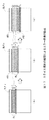
そこで、図15(A)に示すように、第2の実施の形態の画像符号化部104は、リフレッシュラインRLを複数のマクロブロックラインで構成すると共に、当該リフレッシュラインRLの先頭をスライス分割する。この場合、リフレッシュラインRLの最下に位置するリフレッシュ境界BDのマクロブロックライン(以下、これを境界MBラインRLbと呼ぶ)は、デブロックフィルタ処理により、未復帰ラインURの影響を受けてしまう。 Therefore, as illustrated in FIG. 15A, the image encoding unit 104 according to the second embodiment configures the refresh line RL with a plurality of macroblock lines and slices the head of the refresh line RL into slices. . In this case, the macroblock line at the refresh boundary BD located at the bottom of the refresh line RL (hereinafter referred to as the boundary MB line RLb) is affected by the unreturned line UR due to the deblock filter process.
しかし、境界MBラインRLb以外のマクロブロックラインは、未復帰ラインURの影響を受けることはなく、正常に復帰することが可能である。なお図では、未復帰ラインURの影響を受けて壊れた画素を囲って示している。 However, macroblock lines other than the boundary MB line RLb are not affected by the non-returned line UR and can return normally. In the figure, pixels that are broken under the influence of the unreturned line UR are surrounded.
そして画像符号化部104は、図15(B)及び(C)に示すように、前のピクチャにおける境界MBラインRLbが再度次のピクチャにおけるリフレッシュラインRLとなるように、リフレッシュラインRLの位置を少なくとも1マクロブロックラインずつ重複されながらリフレッシュラインRLを変動させる。これにより、画像符号化部104は、前のピクチャにおいてデブロックフィルタ処理によって境界MBラインRLbを破壊させるものの、次のピクチャにおいて当該境界MBラインRLbを復帰させることができる。 Then, as shown in FIGS. 15B and 15C, the image encoding unit 104 sets the position of the refresh line RL so that the boundary MB line RLb in the previous picture becomes the refresh line RL in the next picture again. The refresh line RL is changed while being overlapped by at least one macroblock line. Accordingly, the image encoding unit 104 can restore the boundary MB line RLb in the next picture, although the boundary MB line RLb is destroyed in the previous picture by the deblocking filter process.
具体的に、画像符号化部104のイントラマクロブロック判定部10は、例えば符号化ライン単位が2マクロブロックラインである場合、リフレッシュラインRLに該当するマクロブロックを強制イントラマクロブロックに決定する。イントラマクロブロック判定部10は、処理対象のマクロブロックが強制イントラマクロブロックでない場合には、処理対象のマクロブロックを符号化効率の観点からIマクロブロック又はPマクロブロックに決定する。
Specifically, the intra macroblock
イントラマクロブロック判定部10は、次のピクチャにおいて、前のピクチャにおける境界MBラインRLbが再度次のピクチャにおけるリフレッシュラインRLとなるように、強制イントラマクロブロックを決定する。すなわち、イントラマクロブロック判定部10は、リフレッシュラインRLを1マクロブロックラインだけ下にずらして出現させる。
In the next picture, the intra macroblock
この結果、復号部32は、デブロックフィルタ処理によりリフレッシュラインRLのうち境界MBラインRLbの下側の画素を破壊させてしまうものの、次のピクチャにおいて当該境界MBラインRLb復帰させることができる。
As a result, the
このように、画像符号化部104は、リフレッシュラインRLのうち、未復帰ラインURとの下側境界となる境界MBラインRLbを次のピクチャにおいて再度リフレッシュラインRLとして出現させる。これにより、復号部32は、デブロックフィルタ処理によって破壊される画素を次のピクチャにおいて担保し、適切に復帰させることができる。
In this manner, the image encoding unit 104 causes the boundary MB line RLb, which is the lower boundary with the unrecovered line UR, of the refresh lines RL to appear again as the refresh line RL in the next picture. Thereby, the
[2−1−2.スライスの分割]
第1の実施の形態において、画像符号化部4は、リフレッシュラインRLの先頭をスライス先頭とした。すなわち、第1の実施の形態においてスライス境界BLは、リフレッシュラインRLの位置変動に伴って移動した。以下、このように位置変動するスライス境界をスライス境界BLmoveと表す。
[2-1-2. Split slice]
In the first embodiment, the
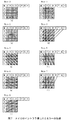
スライス境界BLmove以外においてデブロックフィルタ処理を実行する場合について着目する。図16に示すように、デブロックフィルタ処理の影響を考慮しない場合におけるエラーからの復帰の成否を左側に、デブロックフィルタ処理の影響を考慮した場合における復号の成否(エラーからの復帰の成否)を右側に○又は×で示している。 Attention is paid to the case where the deblocking filter processing is executed outside the slice boundary BLmove. As shown in FIG. 16, the success or failure of recovery from an error when the influence of deblocking filter processing is not taken into account is shown on the left side, and the success or failure of decoding when the influence of deblocking filter processing is taken into consideration (success or failure of return from error) Is indicated by ○ or × on the right side.
図16(A)に示すように、リフレッシュラインRLは、画面内予測処理により問題なく復号される。しかしながら、境界MBラインRLbは、デブロックフィルタ処理により隣接画素が破壊される。 As shown in FIG. 16A, the refresh line RL is decoded without any problem by the intra prediction process. However, in the boundary MB line RLb, adjacent pixels are destroyed by the deblocking filter process.
図16(B)に示すように、復帰済ラインAR1は、境界MBラインRLbのうちエラーの伝搬しない範囲及びリフレッシュラインRLを参照するため、問題なく復号される。しかしながら、復帰済ラインARは、その上部が未復帰ラインURを用いてデブロックフィルタ処理されるため、隣接画素が破壊される。 As shown in FIG. 16B, the restored line AR1 is decoded without any problem because it refers to the boundary MB line RLb in which no error propagates and the refresh line RL. However, since the restored line AR is subjected to deblock filter processing using the non-returned line UR, adjacent pixels are destroyed.
図16(C)に示すように、復帰済ラインAR2は、境界MBラインRLbのうちエラーの伝搬しない範囲及びリフレッシュラインRLを参照するため、問題なく復号される。しかしながら、復帰済ラインAR3は、隣接画素の壊れた復帰済ラインAR1を参照するため、エラーが伝搬する。復帰済ラインAR2は、エラーの伝搬した復帰済ラインAR3を用いてデブロックフィルタ処理がなされるため、エラーが伝搬する。 As shown in FIG. 16C, the restored line AR2 is decoded without any problem because it refers to the range of the boundary MB line RLb in which no error propagates and the refresh line RL. However, since the restored line AR3 refers to the restored line AR1 in which the adjacent pixel is broken, an error propagates. Since the restored line AR2 is subjected to deblock filter processing using the restored line AR3 in which the error has been propagated, an error propagates.
このように、スライス境界BLmoveが変動する場合、インター復号化される復帰済ラインARは、デブロックフィルタ処理の影響により、エラーを伝搬させてしまい、エラーからの復帰が困難となる。 Thus, when the slice boundary BLmove fluctuates, the restored line AR that is inter-decoded propagates an error due to the influence of the deblocking filter process, and it is difficult to recover from the error.
そこで第2の実施の形態における画像符号化部104は、スライス境界をスライス境界BLfixとして固定する。 Therefore, the image encoding unit 104 in the second embodiment fixes the slice boundary as the slice boundary BLfix.
図17(A)に示すように、リフレッシュラインRLは、画面内予測処理により問題なく復号される。しかしながら、境界MBラインRLbは、デブロックフィルタ処理により境界画素が破壊される。 As shown in FIG. 17A, the refresh line RL is decoded without any problem by the intra prediction process. However, in the boundary MB line RLb, the boundary pixel is destroyed by the deblocking filter process.
図17(B)に示すように、スライス境界BLfixが移動しないため、スライス先頭は復帰済ラインAR1となる。復帰済ラインAR1は、境界MBラインRLbのうちエラーの伝搬しない範囲及びリフレッシュラインRLを参照し、問題なく復号される。この復帰済ラインAR1は、スライス境界BLfixに位置するため、未復帰ラインURとの境界においてデブロックフィルタ処理が実行されない。このため復帰済ラインAR1は、境界画素が破壊されることなくエラー復帰することができる。 As shown in FIG. 17B, since the slice boundary BLfix does not move, the top of the slice is the restored line AR1. The restored line AR1 is decoded without any problem with reference to the range of the boundary MB line RLb in which no error propagates and the refresh line RL. Since the restored line AR1 is located at the slice boundary BLfix, the deblocking filter process is not executed at the boundary with the non-restored line UR. Therefore, the restored line AR1 can return to an error without destroying the boundary pixel.
図17(C)に示すように、復帰済ラインAR2及びAR3は、動き予測処理により問題なく復号される。このとき、復帰済ラインAR3は、スライス先頭となるため、デブロックフィルタ処理が実行されず、エラーの伝搬がない。復帰済ラインAR2は、エラーの伝搬がない復帰済ラインAR3を用いてデブロックフィルタ処理が実行されるため、エラーが伝搬されない。 As shown in FIG. 17C, the restored lines AR2 and AR3 are decoded without any problem by the motion prediction process. At this time, since the restored line AR3 is the head of the slice, the deblocking filter process is not executed and no error is propagated. Since the deblocking filter process is executed on the restored line AR2 using the restored line AR3 in which no error is propagated, no error is propagated.
このように、スライス境界BLfixを固定することにより、デブロックフィルタ処理に起因するエラーの伝搬を防止することができる。なお、この第2の実施の形態では、リフレッシュラインRLがスライス先頭となってからエラーの復帰が開始されるため、エラー復帰に2T−1だけ要することになり、第1の実施の形態よりも若干時間を要することになる。 In this way, by fixing the slice boundary BLfix, it is possible to prevent the propagation of errors due to the deblocking filter process. In the second embodiment, since the error recovery starts after the refresh line RL is at the head of the slice, only 2T-1 is required for the error recovery, which is more than in the first embodiment. It will take some time.
具体的に、画像符号化部104におけるピクチャヘッダ生成部9は、スライス分割をするか否かを表すフラグを「true」に設定すると共に、スライス分割閾値を設定する。スライス分割閾値は、ピクチャの先頭からスライス分割を実施すべきマクロブロックの数を表すものであり、スライス境界BLfixの位置を表している。
Specifically, the picture
スライス分割判定部11は、第1の実施の形態と同様、MBカウンタによりピクチャ先頭からのマクロブロックの数をカウントする。スライス分割判定部11は、ピクチャヘッダを確認し、スライス分割をするか否かを表すフラグが「true」であることを確認すると、処理対象となるマクロブロックがスライス分割閾値以上であるか否かを判別する。 Similarly to the first embodiment, the slice division determination unit 11 counts the number of macroblocks from the top of the picture using an MB counter. When the slice division determination unit 11 confirms the picture header and confirms that the flag indicating whether or not to perform slice division is “true”, whether or not the macroblock to be processed is equal to or greater than the slice division threshold value. Is determined.
スライス分割判定部11は、現在のMBカウンタの値がスライス分割閾値以上である場合、スライス分割を実行すべきと判定し、当該判定結果をスライスヘッダ生成部12に供給する。スライスヘッダ生成部12は、スライスヘッダを生成し、画像データS4に付加することにより、スライス分割を実行する。
The slice division determination unit 11 determines that the slice division should be executed when the current MB counter value is equal to or greater than the slice division threshold, and supplies the determination result to the slice
このように、予め定められた位置でスライス分割を実行することにより、デブロックフィルタ処理によるエラーの伝搬を防止することができる。 Thus, by executing slice division at a predetermined position, it is possible to prevent error propagation due to deblocking filter processing.
[2−2.第2のエラー伝搬要因の回避]
上述したように、第2の実施の形態による画像符号化部104は、リフレッシュラインRLの先頭をスライス先頭にしない。しかしながら、図17に示したように、スライス境界BLfixを固定したことにより、スライス境界BLfix及びリフレッシュラインRL間のインター符号化ラインが復帰する。
[2-2. Avoiding second error propagation factor]
As described above, the image encoding unit 104 according to the second embodiment does not set the head of the refresh line RL as the head of the slice. However, as shown in FIG. 17, by fixing the slice boundary BLfix, the inter coding line between the slice boundary BLfix and the refresh line RL is restored.
すなわち、リフレッシュラインRLが参照する可能性のあるインター符号化ラインは既に復帰しており、当該インター符号化ラインを参照対象ブロックとしても特に問題は生じない。 In other words, the inter coding line that can be referred to by the refresh line RL has already been restored, and there is no particular problem even if the inter coding line is used as a reference target block.
[2−3.第1のエラー伝搬要因の回避]
ここで、境界MBラインRLbにおいて、デブロックフィルタ処理により破壊されるのは、画像符号化部104は、未復帰ラインURと隣接する2画素の境界画素のみである。そこで、画像符号化部104は、前のピクチャの符号化ライン単位に加え、境界MBラインRLbにおいて未復帰ラインURの影響を受けない画素を動きベクトルの探索範囲に設定する。
[2-3. Avoiding the first error propagation factor]
Here, in the boundary MB line RLb, the image coding unit 104 only destroys two boundary pixels adjacent to the unrecovered line UR that are destroyed by the deblocking filter process. Therefore, the image encoding unit 104 sets pixels not affected by the unrecovered line UR in the boundary MB line RLb as the motion vector search range in addition to the encoded line unit of the previous picture.
図18に示すように、境界MBラインRLbでは、境界画素が当該未復帰ラインURの影響を受けて壊れてしまう。このため、境界画素を参照して生成された1/2画素及び1/4画素は、未復帰ラインURの影響を受けて、エラーを伝搬するエラー伝搬画素となってしまう。このため、画像符号化部104は、境界画素及びエラー伝搬画素を除く範囲を動きベクトルの探索範囲に設定する。 As shown in FIG. 18, in the boundary MB line RLb, the boundary pixel is broken under the influence of the unreturned line UR. For this reason, the ½ pixel and the ¼ pixel generated with reference to the boundary pixel are affected by the unrecovered line UR and become error propagation pixels that propagate an error. Therefore, the image encoding unit 104 sets a range excluding boundary pixels and error propagation pixels as a motion vector search range.
すなわち、図19(A)に示すように、画像符号化部104の探索範囲設定部16は、処理対象となる次のピクチャの符号化ライン単位(図19(B))に対し、前のピクチャの対応する符号化ライン単位(上側のエラー伝搬画素を除く)をy方向の探索範囲に設定する。さらに探索範囲設定部16は、前のピクチャの対応する符号化ライン単位の直下の符号化ライン単位の一部を動きベクトルのy方向の探索範囲に設定する。この符号化ライン単位の一部は、上側のエラー伝搬画素及び下側の境界画素及びエラー伝搬画素を除いた範囲である。
That is, as shown in FIG. 19A, the search
具体的に、探索範囲設定部16は、整数精度で動きベクトルを検出する際、y方向の探索範囲として、前のピクチャの対応する符号化ライン単位に加え、直下の符号化ライン単位における境界画素を除く14画素をy方向の探索範囲として設定する。なおx方向の探索範囲は制限なしとする。
Specifically, when detecting a motion vector with integer precision, the search
探索範囲設定部16は、1/4精度で動きベクトルを検出する際、y方向の探索範囲として、前のピクチャの対応する符号化ライン単位(エラー伝搬画素を除く)に加え、直下の符号化ライン単位における境界画素及びエラー伝搬画素を除く画素(白抜き及び三角で示す)をy方向の探索範囲として設定する。
When detecting a motion vector with 1/4 accuracy, the search
これにより、画像符号化部104は、動きベクトルの探索範囲をy方向に大きく設定することができるため、符号化効率を向上させ得る。 As a result, the image encoding unit 104 can set the motion vector search range large in the y direction, which can improve encoding efficiency.
このように、画像符号化部104は、エラーの伝搬しない範囲を動きベクトルの探索範囲に設定することにより、エラーの伝搬を防止しつつ符号化効率を向上させるようになされている。 As described above, the image encoding unit 104 is configured to improve encoding efficiency while preventing error propagation by setting a range in which no error is propagated as a motion vector search range.
以上説明したように、第2の実施の形態では、デブロックフィルタ処理を実行して画質を向上させつつ、復号時のエラーの伝搬を防止し得るようになされている。 As described above, in the second embodiment, it is possible to prevent the propagation of errors during decoding while executing the deblock filter process to improve the image quality.
[2−4.処理手順]
次に、第2の実施の形態における処理手順について、図20〜図21のフローチャートを用いて説明する。第2の実施の形態では、第1の実施の形態と同様に符号化処理手順RT1(図11)を実行するものの、ステップSP4においてサブルーチンSRT22を実行し、ステップSP7においサブルーチンSRT23を実行する。ここでは、サブルーチンSRT22及び23についてのみ説明する。
[2-4. Processing procedure]
Next, a processing procedure in the second embodiment will be described with reference to the flowcharts of FIGS. In the second embodiment, the encoding processing procedure RT1 (FIG. 11) is executed as in the first embodiment, but the subroutine SRT22 is executed in step SP4, and the subroutine SRT23 is executed in step SP7. Here, only the subroutines SRT22 and 23 will be described.
画像符号化部104は、符号化処理手順RT1(図11)のステップSP4からサブルーチンSRT22(図20)のステップSP71へ移り、スライス分割判別処理を実行する。 The image encoding unit 104 proceeds from step SP4 of the encoding processing procedure RT1 (FIG. 11) to step SP71 of the subroutine SRT22 (FIG. 20), and executes slice division determination processing.
ステップSP71において、画像符号化部104は、処理対象のマクロブロックに関し、以下の2つの条件を全て満たすか否かについて判別する。
1)スライス分割をするか否かを決定するフラグが「true」である
2)現在のSMBカウンタがスライス分割閾値以上である
In step SP71, the image encoding unit 104 determines whether or not all of the following two conditions are satisfied regarding the macroblock to be processed.
1) The flag for determining whether or not to divide the slice is “true”. 2) The current SMB counter is equal to or greater than the slice division threshold.
ここで肯定結果が得られた場合、このことは、ピクチャを複数のスライスに分割することが予め定められており、現在のSMBカウンタの値(すなわちマクロブロックの位置)から、スライス分割すべきであることを表している。このとき、画像符号化部104は、次のステップSP72へ移る。 If a positive result is obtained here, this means that the picture is predetermined to be divided into a plurality of slices, and the slice value should be divided from the current SMB counter value (that is, the position of the macroblock). It represents something. At this time, the image encoding unit 104 proceeds to the next step SP72.
ステップSP73において、画像符号化部104は、処理対象のマクロブロックから新規スライスとなるようスライス分割を実行すると共に、SMBカウンタの値をリセットする。このとき、画像符号化部104は、disable_deblocking_filter_idcを設定する。そして、画像符号化部104は、符号化処理手順RT1(図11)のステップSP5へ移る。 In step SP73, the image encoding unit 104 executes slice division so that a new slice is formed from the macroblock to be processed, and resets the value of the SMB counter. At this time, the image encoding unit 104 sets disable_deblocking_filter_idc. Then, the image encoding unit 104 proceeds to step SP5 of the encoding processing procedure RT1 (FIG. 11).
これに対して、ステップSP72において、否定結果が得られた場合、このことは、ピクチャを複数のスライスに分割する必要がない、又は現在のSMBカウンタの値(すなわちマクロブロックの位置)から、スライス分割すべきでないことを表している。このとき、画像符号化部104は、次のステップSP73へ移る。 On the other hand, if a negative result is obtained in step SP72, this means that it is not necessary to divide the picture into a plurality of slices, or from the current SMB counter value (ie, the position of the macroblock) Indicates that it should not be divided. At this time, the image encoding unit 104 proceeds to the next step SP73.
ステップSP72において、画像符号化部104は、スライス分割をすることなく、符号化処理手順RT1(図11)のステップSP5へ移る。 In step SP72, the image encoding unit 104 proceeds to step SP5 of the encoding processing procedure RT1 (FIG. 11) without performing slice division.
符号化処理手順RT1のステップSP7において、画像符号化部104は、探索範囲設定処理手順を表すサブルーチンSRT23のステップSP81へ移る。 In step SP7 of the encoding processing procedure RT1, the image encoding unit 104 proceeds to step SP81 of the subroutine SRT23 representing the search range setting processing procedure.
ステップSP81において、画像符号化部104は、エラーの伝搬しない範囲を設定すると、符号化処理手順RT1(図11)のステップSP8へ移る。なお、第2の実施の形態において、エラーの伝搬しない探索範囲とは、x方向に規格上許容される最大値、y方向に、前のピクチャの対応する符号化ライン単位(上側のエラー伝搬画素を除く)、及び前のピクチャの対応する符号化ライン単位の直下の符号化ライン単位の一部である。この符号化ライン単位の一部は、上側のエラー伝搬画素及び下側の境界画素及びエラー伝搬画素を除いた範囲である。 In step SP81, when the image encoding unit 104 sets a range in which no error propagates, the image encoding unit 104 proceeds to step SP8 of the encoding processing procedure RT1 (FIG. 11). In the second embodiment, the search range in which no error propagates is the maximum value allowed in the standard in the x direction, and the corresponding encoded line unit (upper error propagation pixel in the previous picture) in the y direction. And a part of the encoding line unit immediately below the corresponding encoding line unit of the previous picture. A part of the coding line unit is a range excluding the upper error propagation pixel, the lower boundary pixel, and the error propagation pixel.
[2−5.動作及び効果]
以上の構成によれば、画像符号化部104は、ピクチャ間において、リフレッシュラインRLが変動方向であるy方向下側へ向けて、リフレッシュラインRLのy方向のマクロブロックの数よりも少なくとも1以上少ない変動数だけ変動するように強制イントラマクロブロックを割り当てる。画像符号化部104は、ピクチャにおける固定位置でスライスを分割すると共に、disable_deblocking_filter_idcを「1」に設定する。画像符号化部104は、ピクチャ間において一定となる固定位置(スライス境界BLfix)でスライスを分割する。
[2-5. Operation and effect]
According to the above configuration, the image encoding unit 104 is at least one more than the number of macroblocks in the y direction of the refresh line RL toward the lower side in the y direction where the refresh line RL is in the changing direction between pictures. A forced intra macroblock is allocated so as to fluctuate by a small fluctuation number. The image encoding unit 104 divides the slice at a fixed position in the picture, and sets disable_deblocking_filter_idc to “1”. The image encoding unit 104 divides a slice at a fixed position (slice boundary BLfix) that is constant between pictures.
復号部32は、ピクチャ間においてリフレッシュラインRLにおけるy方向下側のリフレッシュ境界BDにおいて未復帰ラインURを参照してデブロックフィルタ処理を実行する。しかし復号部32は、当該リフレッシュ境界のリフレッシュラインRLを次のピクチャにおいて重複して出現させるため、デブロックフィルタ処理によって破壊されたマクロブロックラインを次のピクチャでエラーから復帰させることができる。
The
また復号部32は、スライス境界BLfixを固定することにより、スライス境界BLfixからリフレッシュラインRLまでの間を復帰済ラインARのみにすることができるため、デブロックフィルタ処理を実行してもエラーの伝搬が生じない。このため、画像符号化部104は、デブロックフィルタ処理によるエラーの伝搬を防止することができる。
Further, since the
また、画面内予測処理についても同様であり、スライス境界BLfixからリフレッシュラインRLまでの間を復帰済ラインARのみにすることができるため、リフレッシュラインRLが上側のインターマクロブロックを参照しても、エラーの伝搬が生じない。このため、画像符号化部104は、画面内予測処理によるエラーの伝搬を防止することができる。 The same applies to the intra prediction process, and since only the restored line AR can be set between the slice boundary BLfix and the refresh line RL, even if the refresh line RL refers to the upper inter macroblock, No error propagation occurs. Therefore, the image encoding unit 104 can prevent error propagation due to the intra-screen prediction process.
画像符号化部104は、以下の範囲を動きベクトルのy方向の探索範囲に設定する。
1)処理対象となるリフレッシュラインRLに対応する参照ピクチャの水平ラインとしてのマクロブロックライン(y方向下側とは逆方向側から、フィルタ処理において参照される隣接画素の数に対応する整数精度未満の画素(すなわちエラー伝搬画素)を除く)
2)参照ピクチャのリフレッシュラインRLに対応する参照ピクチャのマクロブロックラインから変動数でなるマクロブロックライン(y方向下側方向から、デブロックフィルタ処理において参照される隣接画素の数に対応する整数精度未満の画素(2画素の境界画素)、並びに動き予測処理におけるフィルタ処理において参照される隣接画素の数(2画素)及びデブロックフィルタ処理において参照される画素の数(2画素)を加算した加算数の画素に対応する整数精度未満の画素(リフレッシュ境界BDから5画素目よりも外側に位置する画素)を除く)。
The image encoding unit 104 sets the following range as a search range in the y direction of the motion vector.
1) A macroblock line as a horizontal line of a reference picture corresponding to a refresh line RL to be processed (less than integer precision corresponding to the number of adjacent pixels referenced in the filter processing from the side opposite to the lower side in the y direction) Pixels (ie error propagation pixels))
2) A macro block line having a variation number from the macro block line of the reference picture corresponding to the refresh line RL of the reference picture (integer precision corresponding to the number of adjacent pixels referenced in the deblocking filter process from the lower side in the y direction) Addition obtained by adding the number of pixels less than 2 (boundary pixels of 2 pixels), the number of adjacent pixels referenced in the filter processing in the motion prediction process (2 pixels), and the number of pixels referenced in the deblocking filter processing (2 pixels) Pixels less than integer precision corresponding to a number of pixels (excluding pixels located outside the fifth pixel from the refresh boundary BD).
これにより、画像符号化部104は、復号時にエラーが伝搬しない範囲として最大限の範囲に動きベクトルの探索範囲を設定することができる。すなわち、画像符号化部104は、リフレッシュブロックRLよりも大きい範囲に動きベクトルの探索範囲を拡大することができるため、符号化効率を向上させることができる。 As a result, the image encoding unit 104 can set the motion vector search range to the maximum range in which an error does not propagate during decoding. That is, since the image encoding unit 104 can expand the motion vector search range to a range larger than the refresh block RL, encoding efficiency can be improved.
以上の構成によれば、画像符号化部104は、スライス境界BLfix以外においてデブロックフィルタ処理を実行すると共に、リフレッシュラインRLを少なくとも1マクロブロックラインずつずらして変動させる。画像符号化部104は、スライス境界BLfixを固定すると共に、disable_deblocking_filter_idcを用いてスライス境界BLfix以外におけるデブロックフィルタ処理を実行する。 According to the above configuration, the image encoding unit 104 performs the deblocking filter processing at a position other than the slice boundary BLfix, and shifts and changes the refresh line RL by at least one macroblock line. The image encoding unit 104 fixes the slice boundary BLfix, and executes deblocking filter processing other than the slice boundary BLfix using disable_deblocking_filter_idc.
これにより、画像符号化部104は、スライス境界BLfix以外においてデブロックフィルタ処理を実行して画質を向上させつつ、エラーの伝搬を防止してエラーから復帰するまでに要する時間を短縮できる。 As a result, the image encoding unit 104 can improve the image quality by executing the deblocking filter processing other than the slice boundary BLfix, and can reduce the time required to recover from the error by preventing the propagation of the error.
<3.第3の実施の形態>
図22〜25に示す第3の実施の形態においては、図2〜図14に示した第1の実施の形態と対応する箇所に同一符号を附して示し、同一部分についての説明を省略する。第3の実施の形態では、リフレッシュラインRLではなく、リフレッシュブロックRL−Bごとにエラー復帰させる点が第1の実施の形態と異なっている。
<3. Third Embodiment>
In the third embodiment shown in FIGS. 22 to 25, parts corresponding to those in the first embodiment shown in FIGS. 2 to 14 are denoted by the same reference numerals, and description of the same parts is omitted. . The third embodiment is different from the first embodiment in that an error is returned not for each refresh line RL but for each refresh block RL-B.
[3−1.本発明の原理]
図22に示すように、本実施の形態では、ピクチャが複数の符号化ブロック単位に分割され、当該符号化ブロック単位ごとに強制イントラマクロブロックが決定される。すなわち、本実施の形態では、リフレッシュラインRLではなく、リフレッシュブロックRL−Bごとにエラーから復帰することになる。
[3-1. Principle of the present invention]
As shown in FIG. 22, in the present embodiment, a picture is divided into a plurality of encoded block units, and a forced intra macroblock is determined for each encoded block unit. In other words, in the present embodiment, not the refresh line RL but each refresh block RL-B returns from the error.
このリフレッシュブロックRL―Bは、任意の構成数でなるマクロブロックで構成される。リフレッシュブロックRL−Bは、例えば4×4マクロブロックや8×8マクロブロックのように、複数のマクロブロックで構成されても良く、1マクロブロックで構成されても良い。 The refresh block RL-B is composed of macroblocks having an arbitrary number of components. The refresh block RL-B may be composed of a plurality of macro blocks, such as a 4 × 4 macro block or an 8 × 8 macro block, and may be composed of one macro block.
本実施の形態では、符号化ブロック単位が並ぶ列ごとにスライスが形成される。このスライスにおいて、リフレッシュブロックRL−Bは、所定の出現数だけ出現する。従って、本実施の形態では、スライスごとの符号量を一定にすることができる。以下、このスライスを定符号量スライスLTと呼ぶ。 In the present embodiment, a slice is formed for each row in which encoded block units are arranged. In this slice, the refresh blocks RL-B appear by a predetermined number of appearances. Therefore, in this embodiment, the code amount for each slice can be made constant. Hereinafter, this slice is referred to as a constant code amount slice LT.
このため、本実施の形態では、無線伝送時のバッファリングによって生じる遅延量を定符号量スライスLTにまで減少させることができる。 For this reason, in this Embodiment, the delay amount produced by the buffering at the time of radio | wireless transmission can be reduced to the constant code amount slice LT.
また、本実施の形態では、符号化ブロック単位ごとにリフレッシュブロックRL−Bを出現させる。各定符号量スライスにおいてリフレッシュブロックRL−Bは、周期Tごとに定期的に出現するものの、各定符号量スライス間におけるリフレッシュブロックRL−Bの位置関係に一定のルールはない。すなわち、リフレッシュブロックRL−Bは、見た目上、あたかもランダムであるかのように出現する。 Further, in the present embodiment, refresh block RL-B appears for each coding block unit. In each constant code amount slice, the refresh block RL-B appears periodically every period T, but there is no fixed rule in the positional relationship of the refresh block RL-B between each constant code amount slice. That is, the refresh block RL-B appears as if it appears to be random.
一般的に、イントラ符号化されたIマクロブロックはインター符号化されたPマクロブロックよりも画質が良い。第1及び第2の実施の形態では、リフレッシュラインRLごとに強制イントラマクロブロックが出現するため、強制イントラマクロブロック及びPマクロブロック間での画質の差異が目立ってしまっていた。 In general, intra-coded I macroblocks have better image quality than inter-coded P macroblocks. In the first and second embodiments, since a forced intra macroblock appears for each refresh line RL, the difference in image quality between the forced intra macroblock and the P macroblock is conspicuous.
本実施の形態では、比較的小さな符号化ブロック単位で強制イントラマクロブロックを出現させることにより、Iマクロブロック及びPマクロブロック間における画質の差異を目立ちにくくでき、ピクチャとしての画質を向上させることができる。なお以下、第3〜第5の実施の形態の符号化方式をランダムリフレッシュ方式と呼び、リフレッシュラインRLごとに強制イントラマクロブロックを出現させる第1及び第2の実施の形態と区別する。 In the present embodiment, by causing forced intra macroblocks to appear in units of relatively small coding blocks, differences in image quality between I macroblocks and P macroblocks can be made inconspicuous, and image quality as a picture can be improved. it can. Hereinafter, the encoding schemes of the third to fifth embodiments are referred to as random refresh schemes, and are distinguished from the first and second embodiments in which a forced intra macroblock appears for each refresh line RL.
[3−2.マクロブロックごとのリフレッシュ]
本実施の形態では、リフレッシュブロックRL−Bが1マクロブロックで構成される場合について説明する。
[3-2. Refresh every macroblock]
In the present embodiment, a case where the refresh block RL-B is composed of one macro block will be described.
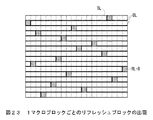
図23に示すように、画像符号化部204は、1マクロブロックラインごとに定符号量スライスを形成し、1マクロブロックごとにリフレッシュブロックRL−Bを出現させる。 As shown in FIG. 23, the image encoding unit 204 forms a constant code amount slice for each macroblock line, and causes a refresh block RL-B to appear for each macroblock.
[3−2−1.第1のエラー伝搬要因の回避]
画像符号化部204の探索範囲設定部16は、x方向及びy方向共に、探索範囲を「0」に設定する。すなわち、動き予測・補償部14は、動きベクトルの検出を実行せず、動きベクトルは常に「0」となる。
[3-2-1. Avoiding the first error propagation factor]
The search
従って、動き予測・補償部14は、前のピクチャの対応するマクロブロックの画素値をそのまま演算器13に供給する。演算器13は、処理対象となるマクロブロックと前のピクチャの対応するマクロブロックの画素値との差分値を差分データL1として出力する。
Therefore, the motion prediction /
これにより、画像符号化部204は、動き予測処理による未復帰のマクロブロック(以下、これを未復帰マクロブロックUMと呼ぶ)からのエラーの伝搬を防止することができる。 Thereby, the image encoding unit 204 can prevent error propagation from an unreturned macroblock (hereinafter referred to as an unreturned macroblock UM) by the motion prediction process.
[3−2−2.第2のエラー伝搬要因の回避]
画像符号化部204は、第1の実施の形態と同様、リフレッシュマクロブロックRL−Bをスライス先頭にすることにより、画面内予測処理における未復帰マクロブロックUMからのエラーの伝搬を防止する。
[3-2-2. Avoiding second error propagation factor]
As in the first embodiment, the image encoding unit 204 prevents the propagation of errors from the unreturned macroblock UM in the intra prediction process by setting the refresh macroblock RL-B to the top of the slice.
具体的に、画像符号化部204のピクチャヘッダ生成部9は、ピクチャヘッダにリフレッシュブロックRL−Bの先頭をスライス先頭にすることを表すフラグを「true」に設定する。
Specifically, the picture
スライス分割判定部11は、リフレッシュブロックRL−Bの先頭をスライス先頭にすることを表すフラグを確認すると、リフレッシュマクロブロックRL−Bの前でスライスを分割する。また、スライス分割判定部11は、処理対象のマクロブロックがピクチャの左端であると、スライスを分割する。すなわち、図23では、リフレッシュブロックRL−Bを含有するスライスとリフレッシュブロックRL−Bを含有しないスライスの2つで定符号量スライスLTを構成する。 When the slice division determination unit 11 confirms the flag indicating that the head of the refresh block RL-B is set to the head of the slice, the slice division determination unit 11 divides the slice before the refresh macroblock RL-B. The slice division determination unit 11 divides the slice when the processing target macroblock is the left end of the picture. That is, in FIG. 23, the constant code amount slice LT is configured by two slices including the refresh block RL-B and a slice not including the refresh block RL-B.
なお、スライス分割判定部11は、リフレッシュブロックRL−Bがピクチャの左端に位置する場合、同一のマクロブロックラインの途中で(例えばリフレッシュブロックRL−Bの直後に)スライス分割を行う。これにより、スライス分割判定部11は、定符号量スライスLTを常に2つのスライスで構成することができる。 Note that, when the refresh block RL-B is located at the left end of the picture, the slice division determination unit 11 performs slice division in the middle of the same macroblock line (for example, immediately after the refresh block RL-B). Accordingly, the slice division determination unit 11 can always configure the constant code amount slice LT by two slices.
イントラ予測部15は、スライスを跨ぐ画素を参照しないため、リフレッシュブロックRL−Bの上及び左の画素を参照せずに画面内予測符号化を実行する。
Since the
これにより、復号部32は、未復帰マクロブロックUMを参照することなく処理対象のマクロブロックを復号し、リフレッシュブロックRL−Bをエラーから復帰させることができる。
As a result, the
[3−2−3.第3のエラー伝搬要因の回避]
スライスヘッダ生成部12は、スライスヘッダを生成する際、disable_deblocking_filter_idc=1に設定する。デブロックフィルタ26は、このフラグを確認すると、デブロックフィルタ処理を実行しない。
[3-2-3. Avoidance of third error propagation factor]
The slice
これにより、画像符号化部204は、デブロックフィルタ処理による未復帰マクロブロックUMからリフレッシュラインRLへのエラーの伝搬を防止でき、リフレッシュブロックRL−Bをエラーから復帰させることができる。 As a result, the image encoding unit 204 can prevent error propagation from the non-returned macroblock UM to the refresh line RL due to the deblocking filter process, and can recover the refresh block RL-B from the error.
[3−2−4.処理手順]
次に、第3の実施の形態における処理手順について、図24のフローチャートを用いて説明する。第3の実施の形態では、第1の実施の形態と同様に符号化処理手順RT1(図11)を実行するものの、ステップSP4においてサブルーチンSRT31を実行し、ステップSP7においサブルーチンSRT23を実行する。ここでは、サブルーチンSRT31及びSRT23についてのみ説明する。
[3-2-4. Processing procedure]
Next, a processing procedure in the third embodiment will be described with reference to the flowchart of FIG. In the third embodiment, the encoding processing procedure RT1 (FIG. 11) is executed as in the first embodiment, but the subroutine SRT31 is executed in step SP4, and the subroutine SRT23 is executed in step SP7. Here, only the subroutines SRT31 and SRT23 will be described.
画像符号化部204は、符号化処理手順RT1(図11)のステップSP4からサブルーチンSRT24(図24)のステップSP101へ移り、スライス分割判別処理を実行する。 The image encoding unit 204 proceeds from step SP4 of the encoding processing procedure RT1 (FIG. 11) to step SP101 of the subroutine SRT24 (FIG. 24), and executes slice division determination processing.
ステップSP101において、画像符号化部204は、処理対象のマクロブロックに関し、以下の2つの条件を全て満たすか否かについて判別する。
1)リフレッシュブロックRL−Bの先頭をスライス先頭にするか否かを決めるフラグが「true」である
2)処理対象のマクロブロックが強制イントラマクロブロックである
In step SP101, the image encoding unit 204 determines whether or not all of the following two conditions are satisfied regarding the macroblock to be processed.
1) The flag that determines whether or not the head of the refresh block RL-B is set to the head of the slice is “true”. 2) The macroblock to be processed is a forced intra macroblock.
ここで肯定結果が得られた場合、このことは、処理対象のマクロブロックがリフレッシュブロックRL―Bであることを表しており、当該処理対象のマクロブロックの直前でスライス分割すべきであることを表している。このとき、画像符号化部204は、次のステップSP102へ移る。 If a positive result is obtained here, this indicates that the macro block to be processed is the refresh block RL-B, and that the slice division should be performed immediately before the macro block to be processed. Represents. At this time, the image encoding unit 204 proceeds to the next step SP102.
ステップSP102において、画像符号化部204は、処理対象のマクロブロックがピクチャの左端であるか否かについて判別し、肯定結果が得られた場合、ステップSP103へ移る一方、否定結果が得られた場合には、ステップSP104へ移る。 In step SP102, the image encoding unit 204 determines whether or not the processing target macroblock is the left end of the picture, and when a positive result is obtained, the process proceeds to step SP103, whereas when a negative result is obtained. Then, the process proceeds to step SP104.
ステップSP103において、画像符号化部204は、処理対象のマクロブロックから新規スライスとなるようスライス分割を実行する。このとき、画像符号化部204は、disable_deblocking_filter_idcを設定する。そして、画像符号化部204は、符号化処理手順RT1(図11)のステップSP5へ移る。 In step SP103, the image encoding unit 204 executes slice division so that a new slice is formed from the macroblock to be processed. At this time, the image encoding unit 204 sets disable_deblocking_filter_idc. Then, the image encoding unit 204 proceeds to step SP5 of the encoding processing procedure RT1 (FIG. 11).
ステップSP105において、画像符号化部204は、スライス分割をすることなく、符号化処理手順RT1(図11)のステップSP5へ移る。 In step SP105, the image encoding unit 204 proceeds to step SP5 of the encoding processing procedure RT1 (FIG. 11) without performing slice division.
ステップSP7において、画像符号化部204は、探索範囲設定処理手順を表すサブルーチンSRT23のステップSP81へ移る。 In step SP7, the image encoding unit 204 proceeds to step SP81 of the subroutine SRT23 representing the search range setting processing procedure.
ステップSP81において、画像符号化部204は、エラーの伝搬しない範囲を設定すると、符号化処理手順RT1(図11)のステップSP8へ移る。なお、第3の実施の形態において、エラーの伝搬しない範囲とは、x方向及びy方向の探索範囲=「0」である。 In step SP81, when the image encoding unit 204 sets a range in which no error is propagated, the image encoding unit 204 proceeds to step SP8 of the encoding processing procedure RT1 (FIG. 11). In the third embodiment, the range in which no error propagates is the search range in the x direction and the y direction = “0”.
ステップSP8において、画像符号化部204は、動きベクトルを「0」として動き予測(すなわち、前のピクチャからの差分値の算出)を実行する。 In step SP8, the image encoding unit 204 performs motion prediction (that is, calculation of a difference value from the previous picture) with the motion vector set to “0”.
[3−2−5.動作及び効果]
以上の構成において、画像符号化部204は、定数のマクロブロックラインにからなる定符号量スライスLTごとにスライス分割する。画像符号化部204は、構成数のマクロブロックで構成されたリフレッシュブロックRL−Bごとに、かつ定符号量スライスLTにおいて出現数だけ強制イントラマクロブロックが出現するように、強制イントラマクロブロックを割り当る。
[3-2-5. Operation and effect]
In the above configuration, the image encoding unit 204 divides a slice for each constant code amount slice LT formed of a constant macroblock line. The image encoding unit 204 allocates forced intra macroblocks so that the number of forced intra macroblocks appears for each refresh block RL-B composed of the number of constituent macroblocks and in the constant code amount slice LT. Hit.
これにより、画像符号化部204は、定符号量スライスLTごとの符号量を一定にすることができるため、バッファリングのために要する遅延量を定符号量スライスLTのサイズまで減少させることができる。 As a result, the image encoding unit 204 can make the code amount for each constant code amount slice LT constant, so that the delay amount required for buffering can be reduced to the size of the constant code amount slice LT. .
画像符号化部204は、単数のマクロブロックがx方向に並ぶことにより定符号量スライスLTを構成し、単数のマクロブロックによりリフレッシュブロックRLを構成する。 The image encoding unit 204 configures a constant code amount slice LT by arranging a single macroblock in the x direction, and configures a refresh block RL by using a single macroblock.
これにより、画像符号化部204は、定符号量スライスLTを1マクロブロックラインにすることができるため、遅延量を1マクロブロックラインにすることができる。 As a result, the image encoding unit 204 can set the constant code amount slice LT to one macroblock line, so that the delay amount can be set to one macroblock line.
画像符号化部204は、ピクチャ内においてランダムに強制イントラマクロブロックを割り当てる。 The image encoding unit 204 assigns forced intra macroblocks randomly in a picture.
これにより、画像符号化部204は、イントラ符号化されるIマクロブロックとインター符号化されるPマクロブロックをランダムに出現させるため、イントラ符号化による画質の高さを目立たせないようにできる。 As a result, the image encoding unit 204 causes the I macroblock to be intra-encoded and the P macroblock to be inter-encoded to appear at random, so that the high image quality due to the intra encoding can be made inconspicuous.
画像符号化部204は、強制イントラマクロブロックの先頭をスライス先頭にし、x方向及びy方向における動きベクトルの探索範囲を「0」とする。 The image encoding unit 204 sets the head of the forced intra macroblock to the head of the slice, and sets the search range of motion vectors in the x direction and the y direction to “0”.
これにより、画像符号化部204は、動き予測処理による復号時のエラーの伝搬を防止することができる。 Accordingly, the image encoding unit 204 can prevent error propagation during decoding by the motion prediction process.
以上の構成によれば、画像符号化部204は、定符号量スライスLTごとにリフレッシュブロックRL−Bを出現させる。これにより、画像符号化部204は、エラーの伝搬を防止してエラーからの復帰に要する時間を短縮しながら、遅延量を小さくすることができる。 According to the above configuration, the image encoding unit 204 causes the refresh block RL-B to appear for each constant code amount slice LT. As a result, the image encoding unit 204 can reduce the delay amount while preventing the propagation of the error and reducing the time required to recover from the error.
<4.第4の実施の形態>
図25に示す第4の実施の形態においては、図22〜図24に示した第3の実施の形態と対応する箇所に同一符号を附して示し、同一部分についての説明を省略する。第4の実施の形態では、リフレッシュブロックRL−Bが1マクロブロックではなく、複数のマクロブロックで構成される点が第3の実施の形態と異なっている。
<4. Fourth Embodiment>
In the fourth embodiment shown in FIG. 25, portions corresponding to those in the third embodiment shown in FIGS. 22 to 24 are denoted by the same reference numerals, and description of the same portions is omitted. The fourth embodiment is different from the third embodiment in that the refresh block RL-B is composed of a plurality of macro blocks instead of one macro block.
[4−1.第1のエラー伝搬要因の回避]
第1の実施の形態では、マクロブロックラインごとにリフレッシュラインRLが出現したため、x方向の動きベクトルの探索範囲に制限を加える必要がなかった。本実施の形態では、未復帰マクロブロックUMを参照させないために、x方向についてもy方向と同様の制限を加える必要がある。
[4-1. Avoiding the first error propagation factor]
In the first embodiment, since the refresh line RL appears for each macroblock line, it is not necessary to limit the search range of the motion vector in the x direction. In the present embodiment, in order not to refer to the non-returned macroblock UM, it is necessary to add the same restriction in the x direction as in the y direction.
画像符号化部304の探索範囲設定部16は、x方向及びy方向の動きベクトルMVx及びMVyの探索範囲を符号化ブロック単位内であり、かつ符号化ブロック単位において外側の3画素よりリフレッシュ境界BD側に存在する1/2画素及び1/4画素を除く範囲に設定する。
The search
なお、マクロブロック判定部11は、ピクチャ間において右側にずれるようにリフレッシュマクロブロックRL−Bを出現させる。このため、復号部32は、リフレッシュマクロブロックRL―Bが出現した後に、インター符号化された符号化ブロック単位の右側について、既に復帰した復帰済ブロックを参照することができる。
The macroblock determination unit 11 causes the refresh macroblock RL-B to appear so as to be shifted to the right side between pictures. For this reason, after the refresh macroblock RL-B appears, the
このため、探索範囲設定部16は、符号化ブロック単位の右側については、リフレッシュ境界BDまでを探索範囲として設定することができる。
For this reason, the search
これにより、画像符号化部304は、未復帰マクロブロックUMからのエラーの伝搬を防止することができる。また、画像符号化部304は、動きベクトルを検出できるため、1マクロブロックごとにリフレッシュブロックRL−Bが出現する第3の実施の形態と比較して、符号化効率を向上させることができる。 As a result, the image encoding unit 304 can prevent error propagation from the unreturned macroblock UM. In addition, since the image encoding unit 304 can detect a motion vector, the encoding efficiency can be improved as compared with the third embodiment in which the refresh block RL-B appears for each macroblock.
[4−2.第2のエラー伝搬要因の回避]
リフレッシュブロックRL−Bが複数のマクロブロックラインにまたがっているため、第3の実施の形態と同様にして当該リフレッシュブロックRL−Bをスライス先頭にするためには、各マクロブロックラインごとにスライス分割を行う必要がある。本実施の形態では、スライス分割の数を減少させるため、constrained_intra_pred_flagを用いて第2のエラー伝搬要因を回避する。
[4-2. Avoiding second error propagation factor]
Since the refresh block RL-B extends over a plurality of macro block lines, the slice division is performed for each macro block line in order to set the refresh block RL-B at the head of the slice as in the third embodiment. Need to do. In this embodiment, in order to reduce the number of slice divisions, the second error propagation factor is avoided using constrained_intra_pred_flag.
画像符号化部304のピクチャヘッダ生成部9は、ピクチャヘッダにおけるPPS(Picture Parameter set)におけるconstrained_intra_pred_flag=1とする。このフラグが「1」であることは、イントラ符号においてインター符号化された画素を参照しないことを表している。
The picture
イントラ予測部15は、constrained_intra_pred_flag=1であることを確認すると、イントラ符号化された画素のみを参照して画面内予測処理を実行する。この結果、復号部32は、イントラ符号化された画素のみを参照して画像データS4を復号することができるため、未復帰ラインURからのエラーの伝搬を防止できる。
When the
このように、画像符号化部304は、constrained_intra_pred_flag=1とすることにより、未復帰ラインURからのエラーの伝搬を防止し得るようになされている。また、画像符号化部304は、リフレッシュブロックRL−Bの2行目及び2列目以降のマクロブロックにおいて隣接するマクロブロックを参照できる。このため、画像符号化部304は、1マクロブロックごとにリフレッシュブロックRL−Bが出現する第3の実施の形態と比較して、符号化効率を向上させることができる。 As described above, the image encoding unit 304 can prevent propagation of errors from the unrecovered line UR by setting constrained_intra_pred_flag = 1. In addition, the image encoding unit 304 can refer to adjacent macroblocks in the second and second macroblocks of the refresh block RL-B. For this reason, the image coding unit 304 can improve the coding efficiency as compared with the third embodiment in which the refresh block RL-B appears for each macroblock.
これにより、復号部32は、未復帰マクロブロックUMを参照することなく処理対象のマクロブロックを復号し、リフレッシュブロックRL−Bをエラーから復帰させることができる。
As a result, the
[4−3.第3のエラー伝搬要因の回避]
スライスヘッダ生成部12は、スライスヘッダを生成する際、disable_deblocking_filter_idc=1に設定する。デブロックフィルタ26は、このフラグを確認すると、当該スライスの全てに対し、デブロックフィルタ処理を実行しない。
[4-3. Avoidance of third error propagation factor]
The slice
これにより、画像符号化部304は、デブロックフィルタ処理による未復帰マクロブロックUMへのエラーの伝搬を防止でき、リフレッシュブロックRL−Bをエラーから復帰させることができる。 Accordingly, the image encoding unit 304 can prevent the error from being propagated to the non-returned macroblock UM due to the deblocking filter process, and can recover the refresh block RL-B from the error.
なお定符号量スライスLTにおけるリフレッシュブロックRL−Bの出現数は、1であっても良く、複数であっても良い。出現数を多くすることにより、周期Tを小さくしてエラーからの復帰を早めることが可能である。一方、出現数を小さくすることにより、インターマクロブロックの割合を高め、符号化効率を向上させることができる。 Note that the number of appearances of the refresh block RL-B in the constant code amount slice LT may be one or plural. By increasing the number of appearances, it is possible to shorten the period T and speed up the recovery from the error. On the other hand, by reducing the number of appearances, it is possible to increase the ratio of inter macroblocks and improve the coding efficiency.
同様に、符号化ブロック単位のサイズを大きくすることにより、動きベクトルの探索範囲を大きく設定して符号化効率を向上させ得る。一方、符号化ブロック単位のサイズを小さくすることにより、定符号量スライスLTを小さくして遅延量を小さくし得ると共に、イントラブロック及びインターブロック間での画質の差異を目立ちにくくすることができる。 Similarly, by increasing the size of the coding block unit, the motion vector search range can be set large to improve the coding efficiency. On the other hand, by reducing the size of each encoded block, the constant code amount slice LT can be reduced to reduce the delay amount, and the difference in image quality between the intra block and the inter block can be made inconspicuous.
符号化ブロック単位の大きさ及びリフレッシュブロックRL−Bの出現数は、上記を踏まえた上で、適宜選択されることが好ましい。 The size of the coding block unit and the number of appearances of the refresh block RL-B are preferably selected as appropriate based on the above.
このように、画像符号化部304は、複数のマクロブロック単位でリフレッシュブロックRL−Bを出現させることにより、動き予測及び画面内予測符号化処理における参照対象を拡大し、符号化効率を向上させることができる。 As described above, the image encoding unit 304 expands the reference target in the motion prediction and intra-frame prediction encoding processing by causing the refresh block RL-B to appear in units of a plurality of macroblocks, and improves the encoding efficiency. be able to.
[4−4.動作及び効果]
以上の構成において、画像符号化部304は、y方向に複数のマクロブロックでなる定符号量スライスLTを構成し、リフレッシュブロックRL−Bは、複数のマクロブロックにより構成する。画像符号化部304は、constrained_intra_pred_flagを「1」に設定する。
[4-4. Operation and effect]
In the above configuration, the image encoding unit 304 configures a constant code amount slice LT including a plurality of macroblocks in the y direction, and the refresh block RL-B includes a plurality of macroblocks. The image encoding unit 304 sets constrained_intra_pred_flag to “1”.
これにより、画像符号化部304は、復号時のエラーの伝搬を防止しつつ、スライス分割の数を減少させると共に、画面内予測処理及び動き予測処理における参照対象ブロックの範囲を拡大して符号化効率を向上させることができる。 As a result, the image encoding unit 304 reduces the number of slice divisions while preventing propagation of errors during decoding, and expands the range of the reference target block in the intra prediction process and the motion prediction process. Efficiency can be improved.
画像符号化部304は、ピクチャ間において、リフレッシュブロックRL−Bが水平右方向(x方向右側)に移動するように、強制イントラブロックを割り当てる。 The image encoding unit 304 assigns forced intra blocks so that the refresh block RL-B moves in the horizontal right direction (right side in the x direction) between pictures.
これにより、画像符号化部304は、ピクチャ間においてリフレッシュブロックRL−Bを隣接させることができるため、リフレッシュブロックRL−Bのx方向右側について、探索範囲をリフレッシュ境界BDまで設定することができる。これにより、画像符号化部304は、探索範囲を拡大して符号化効率を向上させることができる。 As a result, the image encoding unit 304 can make the refresh block RL-B adjacent between pictures, so that the search range can be set up to the refresh boundary BD on the right side in the x direction of the refresh block RL-B. Thereby, the image encoding unit 304 can expand the search range and improve the encoding efficiency.
画像符号化部304は、参照ピクチャにおけるリフレッシュブロック(x方向右側以外のリフレッシュブロックの境界からフィルタ処理において参照される隣接画素の数に対応する整数精度未満の画素を除く)を探索範囲とする。 The image coding unit 304 sets a refresh block in the reference picture (excluding pixels with less than integer precision corresponding to the number of adjacent pixels referenced in the filtering process from the boundary of the refresh block other than the right side in the x direction) as a search range.
これにより、画像符号化部304は、復号時の動き予測処理におけるエラーの伝搬を防止できる。 As a result, the image encoding unit 304 can prevent error propagation in the motion prediction process during decoding.
以上の構成によれば、画像符号化部304は、複数のマクロブロックでリフレッシュブロックRL−Bを構成することにより、遅延量を抑制しつつ、参照対象ブロックを拡大及びスライス数を減少させ、符号化効率を向上させることができる。 According to the above configuration, the image encoding unit 304 configures the refresh block RL-B with a plurality of macroblocks, thereby expanding the reference target block and reducing the number of slices while suppressing the delay amount. Efficiency can be improved.
<5.第5の実施の形態>
図26に示す第5の実施の形態においては、図25に示した第4の実施の形態と対応する箇所に同一符号を附して示し、同一部分についての説明を省略する。第5の実施の形態では、1マクロブロックラインを定符号量スライスLTとする点、及びデブロックフィルタ処理を実行する点が第4の実施の形態と異なっている。
<5. Fifth embodiment>
In the fifth embodiment shown in FIG. 26, portions corresponding to those in the fourth embodiment shown in FIG. 25 are denoted by the same reference numerals, and description of the same portions is omitted. The fifth embodiment is different from the fourth embodiment in that one macroblock line is used as a constant code amount slice LT and that a deblock filter process is executed.
[5−1.本発明の利点]
本実施の形態において、画像符号化部404は、1マクロブロックラインごとにスライス分割を実行すると共に、リフレッシュブロックRL−Bの先頭でスライス分割を実行する。すなわち、画像符号化部404は、第3の実施の形態と同様、1マクロブロックラインを定符号量スライスLTとすることができ、遅延量を低減できる。
[5-1. Advantages of the present invention]
In the present embodiment, the image encoding unit 404 executes slice division for each macroblock line and executes slice division at the head of the refresh block RL-B. That is, as in the third embodiment, the image encoding unit 404 can set one macroblock line as the constant code amount slice LT, and can reduce the delay amount.
図26に示すように、本実施の形態において、リフレッシュブロックRL−Bは、例えば4×3マクロブロックごとに出現する。 As shown in FIG. 26, in the present embodiment, the refresh block RL-B appears, for example, every 4 × 3 macroblocks.
これにより、画像符号化部404は、第4の実施の形態と同様、動き予測及び画面内予測における参照範囲を拡大し、符号化効率を向上させることができる。 Thereby, the image coding unit 404 can expand the reference range in motion prediction and intra-screen prediction and improve the coding efficiency, as in the fourth embodiment.
[5−2.第3のエラー伝搬要因の回避]
画像符号化部404のスライスヘッダ生成部12は、スライスヘッダを生成する際、disable_deblocking_filter_idc=2に設定する。デブロックフィルタ26は、このフラグを確認すると、スライス境界BLに対してデブロックフィルタ処理を実行しない。
[5-2. Avoidance of third error propagation factor]
The slice
画像符号化部404のスライス分割部11は、各マクロブロックライン内(定符号量スライスLT内)において、常に固定された位置でスライス分割を実行する。同一のリフレッシュブロックRL−Bを出現させる定符号量スライスLTでは、x方向に同一位置でスライス分割が実行される。この結果、スライス境界BLfixは、ある1枚のピクチャにおいて、リフレッシュブロックRL−Bの左端に沿うように生成される。 The slice division unit 11 of the image encoding unit 404 executes slice division at a fixed position in each macroblock line (in the constant code amount slice LT). In the constant code amount slice LT in which the same refresh block RL-B appears, slice division is executed at the same position in the x direction. As a result, the slice boundary BLfix is generated along the left end of the refresh block RL-B in a certain picture.
このとき、デブロックフィルタ処理の影響により、リフレッシュブロックRL−Bにおいてスライス境界とならない右側部分の2画素が破壊される(囲んで示す)。このため、イントラマクロブロック判定部10は、図26(B)に示すように、次のピクチャにおいて、破壊される画素を有するマクロブロックが重複するように、リフレッシュブロックRL−Bを2マクロブロックだけ右側にずらした位置に出現させる。
At this time, due to the influence of the deblocking filter processing, the two pixels on the right side that do not become the slice boundary in the refresh block RL-B are destroyed (enclosed). For this reason, as shown in FIG. 26B, the intra macroblock
これにより、復号部32は、エラー時において、未復帰ブロックUR−Bを用いたデブロックフィルタ処理により破壊されるマクロブロックを、次のピクチャにおいて適切に復帰させることができる。
Accordingly, the
このように、画像符号化部404は、1マクロブロックラインごとに定符号量スライスを形成しつつ、複数ブロック単位でリフレッシュブロックRL−Bを出現させる。これにより、画像符号化部404は、動き予測及び画面内予測符号化による参照対象ブロックを増大させて符号化効率を向上させつつ、遅延量を低減させることができる。 As described above, the image encoding unit 404 causes the refresh block RL-B to appear in units of a plurality of blocks while forming a constant code amount slice for each macroblock line. Thereby, the image encoding unit 404 can reduce the delay amount while increasing the reference target block by the motion prediction and the intra prediction encoding to improve the encoding efficiency.
[5−3.動作及び効果]
以上の構成において、画像符号化部404は、単数の符号化単位が水平方向に並ぶことにより定符号量スライスLTを構成する。画像符号化部404は、複数の定符号量スライスLTにおけるx方向の同一位置に、強制イントラマクロブロックが連なることによりリフレッシュブロックRL−Bを構成する。
[5-3. Operation and effect]
In the above configuration, the image encoding unit 404 configures the constant code amount slice LT by arranging a single encoding unit in the horizontal direction. The image encoding unit 404 configures the refresh block RL-B by connecting forced intra macroblocks at the same position in the x direction in a plurality of constant code amount slices LT.
これにより、画像符号化部404は、1マクロブロックラインごとに形成された定符号量スライスLTを跨いでリフレッシュブロックRL−Bを形成することができる。すなわち、画像符号化部404は、定符号量スライスLTを小さくして遅延量を抑制しつつ、リフレッシュブロックRL−Bを大きくして参照対象ブロックを拡大し、符号化効率を向上させることができる。 Thereby, the image encoding unit 404 can form the refresh block RL-B across the constant code amount slice LT formed for each macroblock line. That is, the image encoding unit 404 can increase the refresh block RL-B and expand the reference target block while reducing the constant code amount slice LT to suppress the delay amount, and improve the encoding efficiency. .
画像符号化部404は、ピクチャ間において、リフレッシュブロックRL−Bにおける少なくとも1以上のマクロブロックが重複するように強制イントラマクロブロックを割り当てる。画像符号化部404は、disable_deblocking_filter_idcを「2」に設定する。 The image encoding unit 404 assigns forced intra macroblocks so that at least one macroblock in the refresh block RL-B overlaps between pictures. The image encoding unit 404 sets disable_deblocking_filter_idc to “2”.
これにより、画像符号化部404は、第2の実施の形態と同様、デブロックフィルタ処理によって破壊されるマクロブロックを次のピクチャにおいて復帰させつつ、スライス境界BL以外の部分についてデブロックフィルタ処理を実行できるため、画質を向上させ得る。 As a result, as in the second embodiment, the image encoding unit 404 performs the deblocking filter process on the portion other than the slice boundary BL while restoring the macroblock destroyed by the deblocking filter process in the next picture. Since it can be executed, the image quality can be improved.
画像符号化部404は、各定符号量スライスLTにおけるリフレッシュブロックRL−Bの先頭をスライスの先頭にする。 The image encoding unit 404 sets the head of the refresh block RL-B in each constant code amount slice LT to the head of the slice.
これにより、画像符号化部404は、第2の実施の形態と同様、復号時の画面内予測処理及びデブロックフィルタ処理によるエラーの伝搬を防止できる。 Thereby, the image coding unit 404 can prevent the propagation of errors due to the intra prediction process and the deblocking filter process at the time of decoding, as in the second embodiment.
以上の構成によれば、画像符号化部404は、定符号量スライスLTを跨いで当該定符号量スライスLTよりもy方向に多くのマクロブロックからなるリフレッシュブロックRL−Bを構成する。 According to the above configuration, the image encoding unit 404 configures the refresh block RL-B including more macroblocks in the y direction than the constant code amount slice LT across the constant code amount slice LT.
これにより、画像符号化部404は、バッファリングによる遅延量を小さくしつつ、参照対象ブロックを拡大し、符号化効率を向上させることができる。 As a result, the image encoding unit 404 can expand the reference target block and improve the encoding efficiency while reducing the delay amount due to buffering.
<6.他の実施の形態>
なお上述した第1の実施の形態においては、x方向にのみ1/2画素及び1/4画素を生成するようにした場合について述べた。本発明はこれに限らず、y方向にも1/2画素及び1/4画素を生成するものの、x方向にのみ検索するようにしても良い。また、y方向にも1/2画素及び1/4画素を生成し、後から当該y方向の1/2画素及び1/4画素を削除するようにしても良い。
<6. Other embodiments>
In the above-described first embodiment, the case where ½ pixels and ¼ pixels are generated only in the x direction has been described. The present invention is not limited to this. Although 1/2 pixels and 1/4 pixels are generated in the y direction, the search may be performed only in the x direction. Alternatively, 1/2 pixel and 1/4 pixel may be generated in the y direction, and the 1/2 pixel and 1/4 pixel in the y direction may be deleted later.
また上述した実施の形態においては、符号化ライン単位=1の場合、動きベクトルMVy=0とするようにした場合について述べた。本発明はこれに限らず、検索する動き検索ブロックのサイズが16×8、8×8、8×4、4×8、4×4の場合には、符号化ライン単位=2以上のときと同様の処理によりy方向の動きベクトルを検出するようにしても良い。 In the above-described embodiment, the case where the motion vector MVy = 0 is set when the encoding line unit = 1 is described. The present invention is not limited to this, and when the size of the motion search block to be searched is 16 × 8, 8 × 8, 8 × 4, 4 × 8, 4 × 4, the encoding line unit is 2 or more. You may make it detect the motion vector of ay direction by the same process.
さらに上述した第1及び第2の実施の形態においては、1ピクチャに1つのリフレッシュラインRLが出現するようにした場合について述べた。本発明はこれに限らず、1ピクチャに複数のリフレッシュラインRLが出現するようにしても良い。本発明は、このリフレッシュラインRLの出現する頻度により、符号化効率を調整することができる。 Further, in the first and second embodiments described above, the case where one refresh line RL appears in one picture has been described. The present invention is not limited to this, and a plurality of refresh lines RL may appear in one picture. In the present invention, the encoding efficiency can be adjusted by the frequency of appearance of the refresh line RL.
さらに上述した第3〜第5実施の形態においては、1つの定符号量ラインに1つのリフレッシュブロックRL−Bが出現するようにした場合について述べた。本発明はこれに限らず、1つの定符号量ラインに複数のリフレッシュブロックRL−Bが出現するようにしても良い。本発明は、このリフレッシュブロックRL−Bの出現する頻度により、符号化効率を調整することができる。 Furthermore, in the above-described third to fifth embodiments, the case where one refresh block RL-B appears in one constant code amount line has been described. The present invention is not limited to this, and a plurality of refresh blocks RL-B may appear in one constant code amount line. In the present invention, the coding efficiency can be adjusted by the frequency of appearance of the refresh block RL-B.
さらに上述した実施の形態においては、符号化単位として16×16画素でなるマクロブロックごとに符号化方式が判定されるようにした場合について述べた。本発明はこれに限らず、符号化単位のサイズに制限はない。 Furthermore, in the above-described embodiment, the case has been described in which the encoding method is determined for each macroblock having 16 × 16 pixels as the encoding unit. The present invention is not limited to this, and there is no limitation on the size of the encoding unit.
さらに上述した実施の形態においては、他ブロックをインターブロック及びイントラブロックに割り当てるようにした場合について述べた。本発明はこれに限らず、例えば全ての他ブロックをインターブロックに割り当てるようにしても良い。 Furthermore, in the above-described embodiment, the case has been described where other blocks are assigned to inter blocks and intra blocks. The present invention is not limited to this. For example, all other blocks may be assigned to inter blocks.
さらに上述した実施の形態においては、強制イントラブロックに対して画面内予測処理を実行するようにした場合について述べた。本発明はこれに限らず、例えば画素値がそのまま符号化されても良く、必ずしも画面内予測処理が実行される必要はない。 Furthermore, in the above-described embodiment, the case where the intra prediction process is executed on the forced intra block has been described. The present invention is not limited to this. For example, the pixel value may be encoded as it is, and it is not always necessary to execute the intra prediction process.
さらに上述した実施の形態においては、disable_deblocking_filter_idcを用いてデブロックフィルタ処理を制限するようにした場合について述べた。本発明はこれに限らず、その制限方法に制限はない。 Further, in the above-described embodiment, the case has been described in which the deblocking filter process is limited using disable_deblocking_filter_idc. The present invention is not limited to this, and there is no limit to the limiting method.
さらに上述した実施の形態においては、リフレッシュラインRLが変動方向としてx方向下側に変動するようにした場合について述べた。本発明はこれに限らず、x方向上側に変動するようにしても良い。この場合、本発明は、リフレッシュ境界BDにおける隣接画素に対応する1/2画素及び1/4画素を含有しないように、変動方向とは逆方向のx方向下側についてのy方向の動きベクトルに対する探索範囲を設定する。これにより、本発明は、上述した実施の形態と同様の効果を奏することができる。 Further, in the above-described embodiment, the case where the refresh line RL is changed to the lower side in the x direction as the changing direction has been described. The present invention is not limited to this, and may be varied upward in the x direction. In this case, the present invention applies to a motion vector in the y direction on the lower side in the x direction opposite to the fluctuation direction so as not to include ½ pixel and ¼ pixel corresponding to adjacent pixels on the refresh boundary BD. Set the search range. Thereby, this invention can have an effect similar to embodiment mentioned above.
さらに上述した実施の形態においては、H.264/AVC方式に従って符号化処理を実行するようにした場合について述べた。本発明はこれに限らず、少なくとも隣接画素を参照した整数精度未満での動き予測処理及びデブロックフィルタ処理が実行される全ての符号化方式に従って符号化処理を実行するようにしても良い。 Further, in the above-described embodiment, H.C. The case where the encoding process is executed according to the H.264 / AVC format has been described. The present invention is not limited to this, and the encoding process may be executed in accordance with all the encoding methods in which the motion prediction process and the deblock filter process with less than integer precision referring to at least adjacent pixels are executed.
さらに上述した第1の実施の形態においては、リフレッシュラインRLがピクチャ間において順次変動するようにした場合について述べた。本発明はこれに限らず、ランダムに出現するようにしても良い。 Further, in the above-described first embodiment, the case where the refresh line RL is sequentially changed between pictures has been described. The present invention is not limited to this, and may appear at random.
さらに上述した第3〜第5の実施の形態においては、リフレッシュブロックRLがピクチャ内においてランダムに出現するようにした場合について述べた。本発明はこれに限らず、一定の規則をもって出現するようにしても良い。 Further, in the third to fifth embodiments described above, the case where the refresh block RL appears randomly in the picture has been described. The present invention is not limited to this, and may appear with a certain rule.
さらに上述した実施の形態においては、ピクチャ間においてリフレッシュブロックRL−Bが水平右方向であるx方向右側に移動するようにした場合について述べた。本発明はこれに限らず、x方向左側に移動するようにしても良い。また、ピクチャ間において必ずしも規則的に移動する必要はなく、ランダムに移動しても良い。 Further, in the above-described embodiment, the case has been described in which the refresh block RL-B moves to the right in the x direction, which is the horizontal right direction, between pictures. The present invention is not limited to this, and may move to the left in the x direction. Further, it is not always necessary to move regularly between pictures, and they may be moved randomly.
さらに上述した第1の実施の形態においては、1マクロブロックラインを定符号量ラインLTとするようにした場合について述べた。本発明はこれに限らず、例えば1/2ラインを定符号量ラインLTとするようにしても良い。これにより、遅延量をさらに小さくできる。 Further, in the above-described first embodiment, the case where one macroblock line is set as the constant code amount line LT has been described. The present invention is not limited to this. For example, the ½ line may be used as the constant code amount line LT. Thereby, the delay amount can be further reduced.
さらに上述した第2の実施の形態においては、ピクチャ間において1符号化ライン単位だけ重複しながらリフレッシュラインRLが変動するようにした場合について述べた。本発明はこれに限らず、少なくとも1マクロブロックラインが重複すれば良く、例えば2以上の符号化ライン単位が重複するようにしても良い。また、符号化ライン単位ごとに重複させる必要はなく、符号化ライン単位に1マクロブロック加算してリフレッシュラインRLを出現させても良い。 Further, in the above-described second embodiment, the case has been described in which the refresh line RL varies while overlapping by one encoded line unit between pictures. The present invention is not limited to this, and it is sufficient that at least one macroblock line overlaps. For example, two or more encoded line units may overlap. Further, there is no need to overlap every coding line unit, and one refresh block RL may appear by adding one macroblock to each coding line unit.
さらに上述した第5の実施の形態においては、ピクチャ間において1マクロブロックだけ重複しながらリフレッシュブロックRL−Bが変動するようにした場合について述べた。本発明はこれに限らず、少なくとも1マクロブロックだけリフレッシュブロックRL−Bがすれば良く、2マクロブロック以上変動するようにしても良い。 Further, in the above-described fifth embodiment, the case where the refresh block RL-B is changed while overlapping only one macroblock between pictures has been described. The present invention is not limited to this, and only the refresh block RL-B needs to be provided for at least one macro block, and may vary by two macro blocks or more.
さらに上述した実施の形態においては、インター符号化の際、直前のピクチャのみを参照するようにした場合について述べた。本発明はこれに限らず、前方向のピクチャを参照すれば良く、例えば2つ前のピクチャを参照しても良い。 Further, in the above-described embodiment, a case has been described in which only the immediately preceding picture is referred to during inter coding. The present invention is not limited to this, and a forward picture may be referred to. For example, a previous picture may be referred to.
さらに上述した実施の形態においては、インター符号化の際、6TAPのFIRフィルタにより、隣接画素として2画素を参照するようにした場合について述べた。本発明はこれに限らず、フィルタのタップ数に制限はなく、例えば1画素又は3画素以上の隣接画素を参照しても良い。 Further, in the above-described embodiment, the case where two pixels are referred to as adjacent pixels by a 6TAP FIR filter at the time of inter coding has been described. The present invention is not limited to this, and the number of taps of the filter is not limited. For example, one pixel or three or more adjacent pixels may be referred to.
さらに上述した実施の形態においては、デブロックフィルタ処理において2画素の隣接画素を参照するようにした場合について述べた。本発明はこれに限らず、参照する画素数に制限はない。 Further, in the above-described embodiment, the case where two adjacent pixels are referred to in the deblocking filter processing has been described. The present invention is not limited to this, and the number of pixels to be referred to is not limited.
さらに上述した実施の形態においては、無線画像データ伝送システムとして、本発明を壁掛けテレビに適用するようにした場合について述べた。本発明はこれに限らず、無線で画像データを送受してリアルタイムで表示する全てのシステムにおいて本発明を適用することができる。 Furthermore, in the above-described embodiment, the case where the present invention is applied to a wall-mounted television as a wireless image data transmission system has been described. The present invention is not limited to this, and the present invention can be applied to all systems that transmit and receive image data wirelessly and display them in real time.
さらに上述した実施の形態においては、無線伝送方式として、IEEE 802.11n方式を適用するようにした場合について述べた。本発明はこれに限らず、無線伝送方式に制限はない。 Further, in the above-described embodiment, the case where the IEEE 802.11n system is applied as the wireless transmission system has been described. The present invention is not limited to this, and there is no limitation on the wireless transmission method.
さらに上述した第3〜第5の実施の形態においては、H.264/AVC方式に適用するようにした場合について述べた。本発明はこれに限らず、例えばMPEG−2方式などの各種符号化方式に適用することも可能である。要は、複数のピクチャによって構成される画像データを受け取る受取部と、受取部によって受け取られた画像データをイントラ符号化及び前方向のインター符号化により符号化する際、一定の周期でピクチャにおける全ての符号化単位が、イントラ符号化される強制イントラブロックとなるように、強制イントラブロック又は当該強制イントラブロック以外の他ブロックに符号化単位を割り当てる強制イントラブロック割当部と、一定の符号量ごとにスライス分割し定符号量スライスを形成するスライス分割部と、上記強制イントラブロック割当部によって割り当てられた上記強制イントラブロックをイントラ符号化するイントラ符号化部と、インター符号化すべきインターブロックをインター符号化するインター符号化部とを有していれば良い。これにより、本発明は、MPEG−2方式にランダムリフレッシュ方式を適用し、遅延量を低減することができる。 Further, in the third to fifth embodiments described above, H.264. The case of applying to the H.264 / AVC format has been described. The present invention is not limited to this, and can also be applied to various encoding systems such as the MPEG-2 system. In short, when receiving image data composed of a plurality of pictures and encoding the image data received by the receiving unit by intra coding and forward inter coding, A compulsory intra block allocating unit that allocates a coding unit to a compulsory intra block or a block other than the compulsory intra block so that the coding unit of the compulsory intra block is intra-encoded, and A slice dividing unit that performs slice division to form a constant code amount slice, an intra coding unit that intra-codes the forced intra block allocated by the forced intra block allocation unit, and inter-coding an inter block to be inter-coded Inter coding section There. Accordingly, the present invention can apply the random refresh method to the MPEG-2 method and reduce the delay amount.
さらに、上述した実施の形態においては、符号化プログラム等をROM又はハードディスクドライブなどに予め格納するようにした場合について述べた。本発明はこれに限らず、メモリースティック(ソニー株式会社の登録商標)などの外部記憶媒体からフラッシュメモリなどにインストールするようにしても良い。また、符号化プログラムなどをUSB(Universal Serial Bus)やEthernet(登録商標)(Institute of Electrical and Electronics Engineers)802.11a/b/gなどの無線LAN(Local Area Network)を介して外部から取得し、さらに、は地上ディジタルテレビジョン放送やBSディジタルテレビジョン放送により配信されるようにしても良い。 Furthermore, in the above-described embodiment, the case where the encoding program or the like is stored in advance in a ROM or a hard disk drive has been described. The present invention is not limited to this, and may be installed in a flash memory or the like from an external storage medium such as a memory stick (registered trademark of Sony Corporation). Also, an encoding program or the like is acquired from the outside via a wireless local area network (USB) such as USB (Universal Serial Bus) or Ethernet (registered trademark) (Institute of Electrical and Electronics Engineers) 802.11a / b / g. Furthermore, it may be distributed by terrestrial digital television broadcasting or BS digital television broadcasting.
さらに上述した実施の形態においては、受取部としてのバッファ8と、強制イントラブロック割当部としてのイントラマクロブロック判定部と、探索範囲設定部としての探索範囲設定部16と、動き予測部としての動き予測・補償部と、デブロックフィルタ制限部としてのスライスヘッダ生成部12と、デブロックフィルタとしてのデブロックフィルタ26とによって画像処理装置としての画像処理装置1を構成するようにした場合について述べた。本発明の画像処理装置は、受取部と、強制イントラブロック割当部と、探索範囲設定部と、動き予測部と、デブロックフィルタ制限部と、デブロックフィルタとを少なくとも有していればよく、例えば画像符号化部4のみから構成されていても良い。さらに本発明は、その他種々の構成による受取部と、強制イントラブロック割当部と、探索範囲設定部と、動き予測部と、デブロックフィルタ制限部と、デブロックフィルタとによって本発明の画像処理装置を構成するようにしても良い。
Further, in the above-described embodiment, the
本発明の符号化装置は、例えば公に配信されるコンテンツを録画する機能を有する各種電子機器に利用することができる。 The encoding device of the present invention can be used for various electronic devices having a function of recording content distributed publicly, for example.
1……画像処理装置、4……画像符号化部、8……バッファ、9……ピクチャヘッダ生成部、10……イントラマクロブロック判定部、11……スライス分割判定部、12……スライスヘッダ生成部、14……動き予測・補償部、15……イントラ予測部、17……直交変換部、18……量子化部、19……レート制御部、20……可逆符号化部、21……蓄積バッファ、23……逆量子化部、24……逆直交変換部、26……デブロックフィルタ、27……フレームメモリ、S4……画像データ、S6……ビットストリーム、L3……ローカルデコード画像。
DESCRIPTION OF
Claims (11)
上記探索範囲設定部において設定された探索範囲で動きベクトルを検出し、動き予測処理を実行する動き予測部と
を有する画像処理装置。 For a reference coding unit in a reference picture to be referenced, a pixel processing with an integer precision adjacent pixel is used to generate a pixel with an integer precision less than the integer precision corresponding to the adjacent pixel, and the error is restored when decoded. A search range setting unit that sets a search range for the reference coding unit so as not to include pixels with less than integer precision generated by referring to no unreturned macroblock;
An image processing apparatus comprising: a motion prediction unit that detects a motion vector in the search range set in the search range setting unit and executes a motion prediction process.
上記参照ピクチャにおけるリフレッシュラインにおいて、当該リフレッシュラインが変動する変動方向とは逆方向側から上記フィルタ処理において参照する隣接画素の数に対応する上記整数精度未満の画素であるエラー伝搬画素を除く範囲を上記探索範囲として設定するIn the refresh line in the reference picture, a range excluding error propagation pixels corresponding to the number of adjacent pixels to be referred to in the filter processing from the direction opposite to the fluctuation direction in which the refresh line fluctuates is excluded. Set as the search range
請求項1に記載の画像処理装置。The image processing apparatus according to claim 1.
デブロックフィルタ処理をスライス境界以外で適用する場合、上側のエラー伝搬画素を除く符号化ライン単位に加え、当該符号化ライン単位の変動方向側に位置する符号化ライン単位のうち、上側のエラー伝搬画素及び下側のエラー伝搬画素と、デブロックフィルタが影響を与える下側の境界画素とを除いた範囲を上記探索範囲に設定するWhen deblocking filter processing is applied outside the slice boundary, in addition to the coding line unit excluding the upper error propagation pixel, the upper error propagation among the coding line units positioned on the fluctuation direction side of the coding line unit. A range excluding the pixel and the lower error propagation pixel and the lower boundary pixel affected by the deblocking filter is set as the search range.
請求項1に記載の画像処理装置。The image processing apparatus according to claim 1.
をさらに有する請求項1に記載の画像処理装置。 When coding image data composed of pictures by intra coding and forward inter coding, so as to be a compulsory intra block in which all coding units in the picture are intra-coded in a certain cycle, The image processing apparatus according to claim 1 , further comprising: a compulsory intra block assigning unit that assigns the coding unit to a compulsory intra block or a block other than the compulsory intra block.
上記参照対象制限部による制限に従って、画面内予測処理を実行するイントラ符号化部と
をさらに有する請求項4に記載の画像処理装置。 A reference target limiting unit that limits a reference target for the compulsory intra block so as not to refer to an encoding processing unit composed of inter blocks to be inter-encoded ,
To the restrictions by the reference target limiting section, an image processing apparatus according to claim 4, further have the intra coding unit which performs intra prediction process.
上記ピクチャにおける水平方向に上記符号化単位が並ぶ水平ラインごとに、リフレッシュラインとして上記強制イントラブロックを割り当てると共に、ピクチャ間において上記リフレッシュラインが変動方向へ向けて変動するように上記強制イントラブロックを割り当てる
請求項5に記載の画像処理装置。 The compulsory intra block allocation unit
The forced intra block is allocated as a refresh line for each horizontal line in which the coding units are arranged in the horizontal direction in the picture, and the forced intra block is allocated so that the refresh line varies in the variation direction between pictures. the image processing apparatus according to claim 5 that.
単数の上記符号化単位が水平方向に並ぶことによりリフレッシュラインが構成されていた場合には、垂直方向の上記探索範囲を「0」に設定する
請求項5に記載の画像処理装置。 The search range setting unit
The image processing apparatus according to claim 5 , wherein when the refresh line is configured by arranging a single encoding unit in a horizontal direction, the search range in the vertical direction is set to “0”.
constrained_intra_pred_flagを「1」に設定し、
上記イントラ符号化部は、
上記constrained_intra_pred_flagに従って、インターマクロブロックを参照することなく上記強制イントラブロックに対する画面内予測処理を実行する
請求項6に記載の画像処理装置。 The reference target restriction unit is
set constrained_intra_pred_flag to “1”,
The intra coding unit is
The image processing apparatus according to claim 6 , wherein an intra-screen prediction process is performed on the forced intra block without referring to an inter macroblock according to the constrained_intra_pred_flag.
上記他ブロックに割り当てた上記符号化単位を、
インター符号化されるインターリフレッシュブロックと、イントラ符号化されるイントラリフレッシュブロックとに割り当て、
上記参照対象制限部は、
上記強制イントラブロックの先頭をスライス先頭にすることを表すフラグを「true」に設定することにより、上記参照対象を制限する
請求項6に記載の画像処理装置。 The compulsory intra block allocation unit
The coding unit assigned to the other block is
Assign to inter-refresh blocks that are inter-coded and intra-refresh blocks that are intra-coded,
The reference target restriction unit is
The image processing apparatus according to claim 6 , wherein the reference target is limited by setting a flag indicating that the head of the forced intra block is set to the head of a slice to “true”.
上記参照ピクチャにおける複数の上記符号化単位により構成されたリフレッシュブロック(上記水平右方向を除く上記リフレッシュブロックの境界から上記フィルタ処理において参照される上記隣接画素の数に対応する上記対応画素を除く)を上記探索範囲とする
請求項6に記載の画像処理装置。 The search range setting unit
A refresh block composed of a plurality of the coding units in the reference picture (excluding the corresponding pixels corresponding to the number of adjacent pixels referenced in the filtering process from the boundary of the refresh block excluding the horizontal right direction) The image processing apparatus according to claim 6 , wherein the search range is set as the search range.
上記探索範囲設定ステップにおいて設定された探索範囲で動きベクトルを検出し、動き予測処理を実行する動き予測ステップと
を有する画像処理方法。 For a reference coding unit in a reference picture to be referenced, a pixel processing with an integer precision adjacent pixel is used to generate a pixel with an integer precision less than the integer precision corresponding to the adjacent pixel, and the error is restored when decoded. A search range setting step for setting a search range for the reference coding unit so as not to include pixels with less than integer precision generated by referring to a non-returned macroblock;
An image processing method comprising: a motion prediction step of detecting a motion vector in the search range set in the search range setting step and executing a motion prediction process.
Priority Applications (4)
| Application Number | Priority Date | Filing Date | Title |
|---|---|---|---|
| JP2009176701A JP5353532B2 (en) | 2009-07-29 | 2009-07-29 | Image processing apparatus and image processing method |
| CN201310051402.XA CN103124355B (en) | 2009-07-29 | 2010-07-22 | Image processing equipment and image processing method |
| CN2010102355768A CN101990097B (en) | 2009-07-29 | 2010-07-22 | Image processing apparatus and image processing method |
| US12/841,661 US8537896B2 (en) | 2009-07-29 | 2010-07-22 | Image processing apparatus and image processing method |
Applications Claiming Priority (1)
| Application Number | Priority Date | Filing Date | Title |
|---|---|---|---|
| JP2009176701A JP5353532B2 (en) | 2009-07-29 | 2009-07-29 | Image processing apparatus and image processing method |
Publications (3)
| Publication Number | Publication Date |
|---|---|
| JP2011035444A JP2011035444A (en) | 2011-02-17 |
| JP2011035444A5 JP2011035444A5 (en) | 2012-07-26 |
| JP5353532B2 true JP5353532B2 (en) | 2013-11-27 |
Family
ID=43526960
Family Applications (1)
| Application Number | Title | Priority Date | Filing Date |
|---|---|---|---|
| JP2009176701A Expired - Fee Related JP5353532B2 (en) | 2009-07-29 | 2009-07-29 | Image processing apparatus and image processing method |
Country Status (3)
| Country | Link |
|---|---|
| US (1) | US8537896B2 (en) |
| JP (1) | JP5353532B2 (en) |
| CN (2) | CN103124355B (en) |
Cited By (1)
| Publication number | Priority date | Publication date | Assignee | Title |
|---|---|---|---|---|
| US11356663B2 (en) | 2018-03-28 | 2022-06-07 | Panasonic Intellectual Property Management Co., Ltd. | Encoder, decoder, encoding method, and decoding method |
Families Citing this family (20)
| Publication number | Priority date | Publication date | Assignee | Title |
|---|---|---|---|---|
| JP5667364B2 (en) * | 2010-02-10 | 2015-02-12 | 株式会社メガチップス | Image encoding device |
| EP2648409B1 (en) * | 2011-03-10 | 2016-08-17 | Nippon Telegraph And Telephone Corporation | Quantization control device and method, and quantization control program |
| WO2012150849A2 (en) * | 2011-05-04 | 2012-11-08 | 한국전자통신연구원 | Video encoding/decoding method using error resilient loop filter, and signaling method thereof |
| KR101954006B1 (en) * | 2011-06-30 | 2019-03-04 | 소니 주식회사 | Image processing device and method |
| JP6034010B2 (en) | 2011-10-24 | 2016-11-30 | ソニー株式会社 | Encoding apparatus, encoding method, and program |
| JP2013110466A (en) * | 2011-11-17 | 2013-06-06 | Hitachi Kokusai Electric Inc | Moving image encoding device |
| JP2013165340A (en) * | 2012-02-09 | 2013-08-22 | Sony Corp | Image processor and image processing method |
| US9819964B2 (en) * | 2012-05-04 | 2017-11-14 | Environmental Systems Research Institute, Inc. | Limited error raster compression |
| US9002126B2 (en) * | 2012-05-04 | 2015-04-07 | Environmental Systems Research Institute (ESRI) | Limited error raster compression |
| WO2015053594A1 (en) | 2013-10-12 | 2015-04-16 | 삼성전자 주식회사 | Video encoding method and apparatus and video decoding method and apparatus using intra block copy prediction |
| JP2015106747A (en) * | 2013-11-28 | 2015-06-08 | 富士通株式会社 | Dynamic image encoding device, dynamic image encoding method and dynamic image encoding computer program |
| US9774881B2 (en) | 2014-01-08 | 2017-09-26 | Microsoft Technology Licensing, Llc | Representing motion vectors in an encoded bitstream |
| US9749642B2 (en) * | 2014-01-08 | 2017-08-29 | Microsoft Technology Licensing, Llc | Selection of motion vector precision |
| WO2016068674A1 (en) * | 2014-10-31 | 2016-05-06 | 삼성전자 주식회사 | Method and device for encoding/decoding motion vector |
| CN110036642A (en) * | 2016-12-07 | 2019-07-19 | 索尼半导体解决方案公司 | Image processing equipment and method |
| JP6977422B2 (en) * | 2017-09-13 | 2021-12-08 | 株式会社Jvcケンウッド | Transcoding device, transcoding method and transcoding program |
| WO2019126170A1 (en) * | 2017-12-19 | 2019-06-27 | Vid Scale, Inc. | Face discontinuity filtering for 360-degree video coding |
| CN112534810A (en) * | 2018-08-06 | 2021-03-19 | 夏普株式会社 | Moving image decoding device and moving image encoding device |
| JP7284375B2 (en) | 2019-01-15 | 2023-05-31 | 富士通株式会社 | Video encoding program and video encoding device |
| CN112970252A (en) * | 2020-07-24 | 2021-06-15 | 深圳市大疆创新科技有限公司 | Video coding and decoding method and device |
Family Cites Families (17)
| Publication number | Priority date | Publication date | Assignee | Title |
|---|---|---|---|---|
| JP3210082B2 (en) * | 1992-07-14 | 2001-09-17 | キヤノン株式会社 | Encoding device and method |
| KR0166725B1 (en) * | 1993-06-30 | 1999-03-20 | 김광호 | Forced intra-frame coding method |
| JPH08126004A (en) * | 1994-10-21 | 1996-05-17 | Mitsubishi Electric Corp | Image coder |
| JPH1141609A (en) | 1997-07-23 | 1999-02-12 | Hitachi Ltd | Signal processor |
| JPH11205803A (en) | 1998-01-19 | 1999-07-30 | Sony Corp | Encoding device and encoding method therefor |
| US6671319B1 (en) * | 1999-12-28 | 2003-12-30 | Sony Corporation | Methods and apparatus for motion estimation using neighboring macroblocks |
| KR20040008359A (en) * | 2002-07-18 | 2004-01-31 | 삼성전자주식회사 | Method for estimating motion using hierarchical search and apparatus thereof and image encoding system using thereof |
| US20050008240A1 (en) * | 2003-05-02 | 2005-01-13 | Ashish Banerji | Stitching of video for continuous presence multipoint video conferencing |
| JP4495013B2 (en) * | 2004-03-17 | 2010-06-30 | パナソニック株式会社 | Video encoding device |
| JP4724061B2 (en) * | 2006-07-06 | 2011-07-13 | 株式会社東芝 | Video encoding device |
| CN101242540B (en) * | 2007-02-09 | 2010-05-19 | 安凯(广州)软件技术有限公司 | Error control method for video decoder chip |
| US8050325B2 (en) * | 2007-06-22 | 2011-11-01 | Samsung Electronics Co., Ltd. | System and method for boundary motion vector correction in motion compensated frame rate |
| JP4821723B2 (en) * | 2007-07-13 | 2011-11-24 | 富士通株式会社 | Moving picture coding apparatus and program |
| JP5152190B2 (en) * | 2007-10-04 | 2013-02-27 | 富士通株式会社 | Encoding device, encoding method, encoding program, and encoding circuit |
| CN101207823A (en) * | 2007-11-22 | 2008-06-25 | 武汉大学 | Method for video encoding of video frequency corresponding synthesis anti-code error |
| CN101232619B (en) * | 2008-01-25 | 2011-05-11 | 浙江大学 | Video encoding method of embedding intraframe coding block |
| US8218644B1 (en) * | 2009-05-12 | 2012-07-10 | Accumulus Technologies Inc. | System for compressing and de-compressing data used in video processing |
-
2009
- 2009-07-29 JP JP2009176701A patent/JP5353532B2/en not_active Expired - Fee Related
-
2010
- 2010-07-22 CN CN201310051402.XA patent/CN103124355B/en active Active
- 2010-07-22 CN CN2010102355768A patent/CN101990097B/en not_active Expired - Fee Related
- 2010-07-22 US US12/841,661 patent/US8537896B2/en active Active
Cited By (1)
| Publication number | Priority date | Publication date | Assignee | Title |
|---|---|---|---|---|
| US11356663B2 (en) | 2018-03-28 | 2022-06-07 | Panasonic Intellectual Property Management Co., Ltd. | Encoder, decoder, encoding method, and decoding method |
Also Published As
| Publication number | Publication date |
|---|---|
| US8537896B2 (en) | 2013-09-17 |
| CN103124355A (en) | 2013-05-29 |
| CN101990097A (en) | 2011-03-23 |
| CN101990097B (en) | 2013-03-27 |
| US20110026597A1 (en) | 2011-02-03 |
| JP2011035444A (en) | 2011-02-17 |
| CN103124355B (en) | 2016-05-11 |
Similar Documents
| Publication | Publication Date | Title |
|---|---|---|
| JP5353532B2 (en) | Image processing apparatus and image processing method | |
| JP5347849B2 (en) | Image encoding apparatus, image receiving apparatus, image encoding method, and image receiving method | |
| KR101962183B1 (en) | Method for encoding/decoding an intra prediction mode and apparatus for the same | |
| TWI556648B (en) | Method for decoding image | |
| TWI573436B (en) | Method and apparatus for parallel entropy encoding, method and apparatus for parallel entropy decoding,and non-transitory computer-readable recording medium | |
| JP6113865B2 (en) | Video encoding method and apparatus for decoder setting, and video decoding method and apparatus based on decoder setting | |
| JP5269593B2 (en) | Encoding device, encoding method, decoding device, decoding method, and program thereof | |
| JP6050488B2 (en) | Multi-layer video encoding method and apparatus for random access, and multi-layer video decoding method and apparatus for random access | |
| KR20110114498A (en) | Method and apparatus for video encoding with deblocking filtering based on tree-structured data unit, and method and apparatus for video decoding with the same | |
| KR20140110221A (en) | Video encoder, method of detecting scene change and method of controlling video encoder | |
| EP2744203A2 (en) | Method for multiview video prediction encoding and device for same, and method for multiview video prediction decoding and device for same | |
| JP6569665B2 (en) | Image decoding apparatus, image decoding method, and integrated circuit | |
| US20220239927A1 (en) | Intra prediction method and apparatus | |
| KR20170078681A (en) | Video encoding method and apparatus using interpolation filter reflecting video characteristics, video decoding method and apparatus | |
| KR102084631B1 (en) | Method and apparatus for determining quantization parameter based on size of tranformation block | |
| KR100644620B1 (en) | Method and apparatus for decoding moving picture which post filtering is applied | |
| US10321150B2 (en) | Motion vector selection and prediction in video coding systems and methods | |
| US10652569B2 (en) | Motion vector selection and prediction in video coding systems and methods | |
| US20140334552A1 (en) | Image decoding device | |
| JP2003018595A (en) | Video encoding system, video decoding system, video encoding method, and video decoding method | |
| JP6874844B2 (en) | Moving image coding device, moving image coding method, and moving image coding program | |
| JP6527384B2 (en) | Video encoding device and program | |
| JPH08265759A (en) | Compression signal switching device |
Legal Events
| Date | Code | Title | Description |
|---|---|---|---|
| A521 | Request for written amendment filed |
Free format text: JAPANESE INTERMEDIATE CODE: A523 Effective date: 20120607 |
|
| A621 | Written request for application examination |
Free format text: JAPANESE INTERMEDIATE CODE: A621 Effective date: 20120607 |
|
| A977 | Report on retrieval |
Free format text: JAPANESE INTERMEDIATE CODE: A971007 Effective date: 20121212 |
|
| A131 | Notification of reasons for refusal |
Free format text: JAPANESE INTERMEDIATE CODE: A131 Effective date: 20130115 |
|
| A521 | Request for written amendment filed |
Free format text: JAPANESE INTERMEDIATE CODE: A523 Effective date: 20130307 |
|
| TRDD | Decision of grant or rejection written | ||
| A01 | Written decision to grant a patent or to grant a registration (utility model) |
Free format text: JAPANESE INTERMEDIATE CODE: A01 Effective date: 20130730 |
|
| A61 | First payment of annual fees (during grant procedure) |
Free format text: JAPANESE INTERMEDIATE CODE: A61 Effective date: 20130812 |
|
| R151 | Written notification of patent or utility model registration |
Ref document number: 5353532 Country of ref document: JP Free format text: JAPANESE INTERMEDIATE CODE: R151 |
|
| R250 | Receipt of annual fees |
Free format text: JAPANESE INTERMEDIATE CODE: R250 |
|
| R250 | Receipt of annual fees |
Free format text: JAPANESE INTERMEDIATE CODE: R250 |
|
| R250 | Receipt of annual fees |
Free format text: JAPANESE INTERMEDIATE CODE: R250 |
|
| R250 | Receipt of annual fees |
Free format text: JAPANESE INTERMEDIATE CODE: R250 |
|
| R250 | Receipt of annual fees |
Free format text: JAPANESE INTERMEDIATE CODE: R250 |
|
| LAPS | Cancellation because of no payment of annual fees |