WO2020031889A1 - 電気機器 - Google Patents
電気機器 Download PDFInfo
- Publication number
- WO2020031889A1 WO2020031889A1 PCT/JP2019/030468 JP2019030468W WO2020031889A1 WO 2020031889 A1 WO2020031889 A1 WO 2020031889A1 JP 2019030468 W JP2019030468 W JP 2019030468W WO 2020031889 A1 WO2020031889 A1 WO 2020031889A1
- Authority
- WO
- WIPO (PCT)
- Prior art keywords
- battery
- batteries
- load
- electric device
- microcomputer
- Prior art date
- Legal status (The legal status is an assumption and is not a legal conclusion. Google has not performed a legal analysis and makes no representation as to the accuracy of the status listed.)
- Ceased
Links
Images





Classifications
-
- H—ELECTRICITY
- H01—ELECTRIC ELEMENTS
- H01M—PROCESSES OR MEANS, e.g. BATTERIES, FOR THE DIRECT CONVERSION OF CHEMICAL ENERGY INTO ELECTRICAL ENERGY
- H01M50/00—Constructional details or processes of manufacture of the non-active parts of electrochemical cells other than fuel cells, e.g. hybrid cells
- H01M50/20—Mountings; Secondary casings or frames; Racks, modules or packs; Suspension devices; Shock absorbers; Transport or carrying devices; Holders
- H01M50/204—Racks, modules or packs for multiple batteries or multiple cells
-
- F—MECHANICAL ENGINEERING; LIGHTING; HEATING; WEAPONS; BLASTING
- F25—REFRIGERATION OR COOLING; COMBINED HEATING AND REFRIGERATION SYSTEMS; HEAT PUMP SYSTEMS; MANUFACTURE OR STORAGE OF ICE; LIQUEFACTION SOLIDIFICATION OF GASES
- F25B—REFRIGERATION MACHINES, PLANTS OR SYSTEMS; COMBINED HEATING AND REFRIGERATION SYSTEMS; HEAT PUMP SYSTEMS
- F25B21/00—Machines, plants or systems, using electric or magnetic effects
- F25B21/02—Machines, plants or systems, using electric or magnetic effects using Peltier effect; using Nernst-Ettinghausen effect
-
- H—ELECTRICITY
- H01—ELECTRIC ELEMENTS
- H01M—PROCESSES OR MEANS, e.g. BATTERIES, FOR THE DIRECT CONVERSION OF CHEMICAL ENERGY INTO ELECTRICAL ENERGY
- H01M10/00—Secondary cells; Manufacture thereof
- H01M10/42—Methods or arrangements for servicing or maintenance of secondary cells or secondary half-cells
-
- H—ELECTRICITY
- H01—ELECTRIC ELEMENTS
- H01M—PROCESSES OR MEANS, e.g. BATTERIES, FOR THE DIRECT CONVERSION OF CHEMICAL ENERGY INTO ELECTRICAL ENERGY
- H01M10/00—Secondary cells; Manufacture thereof
- H01M10/42—Methods or arrangements for servicing or maintenance of secondary cells or secondary half-cells
- H01M10/44—Methods for charging or discharging
-
- H—ELECTRICITY
- H01—ELECTRIC ELEMENTS
- H01M—PROCESSES OR MEANS, e.g. BATTERIES, FOR THE DIRECT CONVERSION OF CHEMICAL ENERGY INTO ELECTRICAL ENERGY
- H01M50/00—Constructional details or processes of manufacture of the non-active parts of electrochemical cells other than fuel cells, e.g. hybrid cells
- H01M50/20—Mountings; Secondary casings or frames; Racks, modules or packs; Suspension devices; Shock absorbers; Transport or carrying devices; Holders
- H01M50/247—Mountings; Secondary casings or frames; Racks, modules or packs; Suspension devices; Shock absorbers; Transport or carrying devices; Holders specially adapted for portable devices, e.g. mobile phones, computers, hand tools or pacemakers
-
- H—ELECTRICITY
- H02—GENERATION; CONVERSION OR DISTRIBUTION OF ELECTRIC POWER
- H02J—ELECTRIC POWER NETWORKS; CIRCUIT ARRANGEMENTS OR SYSTEMS FOR SUPPLYING OR DISTRIBUTING ELECTRIC POWER; SYSTEMS FOR STORING ELECTRIC ENERGY
- H02J7/00—Circuit arrangements for charging or discharging batteries or for supplying loads from batteries
-
- Y—GENERAL TAGGING OF NEW TECHNOLOGICAL DEVELOPMENTS; GENERAL TAGGING OF CROSS-SECTIONAL TECHNOLOGIES SPANNING OVER SEVERAL SECTIONS OF THE IPC; TECHNICAL SUBJECTS COVERED BY FORMER USPC CROSS-REFERENCE ART COLLECTIONS [XRACs] AND DIGESTS
- Y02—TECHNOLOGIES OR APPLICATIONS FOR MITIGATION OR ADAPTATION AGAINST CLIMATE CHANGE
- Y02E—REDUCTION OF GREENHOUSE GAS [GHG] EMISSIONS, RELATED TO ENERGY GENERATION, TRANSMISSION OR DISTRIBUTION
- Y02E60/00—Enabling technologies; Technologies with a potential or indirect contribution to GHG emissions mitigation
- Y02E60/10—Energy storage using batteries
Definitions
- the present invention relates to an electric device that can be driven by a battery.
- a portable portable cold storage that has a housing capable of housing food and the like and that can cool the food and the like (housing material) housed in the housing is commercially available (Patent) Reference 1).
- the cool box described in Patent Literature 1 cools the contents by driving a Peltier element with an external power supply in a place where an external power supply can be used. At this time, cooling while charging the mounted battery pack is possible. In a place where an external power supply cannot be used, the contents are cooled by driving the Peltier element using the charged power of the internal battery.
- a Peltier device is a semiconductor device that can freely control temperature such as cooling or heating by a direct current, and can generate a temperature difference between both surfaces of the device.
- the present invention has been made in view of the above background, and an object of the present invention is to provide an electric device that ensures stable operation of an electric device that uses a plurality of batteries by switching. Another object of the present invention is to provide an electric device with improved workability during use. Still another object of the present invention is to provide an electric device that can be efficiently used with a simple configuration.
- a load operated by electric power a plurality of batteries capable of supplying electric power to the load, a control unit that switches connection and disconnection between each of the plurality of batteries and the load,
- the predetermined reuse condition includes that the use-inhibited battery is re-installed after being removed from the main body.
- the predetermined use stop condition includes that an output voltage of the connected battery falls below a predetermined overdischarge threshold.
- the control unit selects one of the plurality of usable batteries having the smallest output voltage as the connection battery.
- the plurality of batteries includes two batteries.
- the apparatus further comprises a charging circuit connectable to an external power supply, and further includes a charging circuit for charging the plurality of batteries with power supplied from the external power supply, wherein the predetermined reuse condition is: , And the charging circuit is supplied with power from an external power supply.
- control unit is electrically connected between each of the plurality of batteries and the load, and connects and disconnects each of the plurality of batteries and the load. It has a plurality of switching units that switch independently of each other.
- the main body includes a container that defines an inside of a container in which articles are stored, and a door that closes an opening in the container. It is a portable cool box that is a Peltier element that cools the inside.
- the load is a motor
- the main body has a head having a dust collection fan driven by the motor, and a dust suction port, and is open to one side.
- a filter provided in the tank and configured to filter air flowing from the suction port toward the opening.
- the battery when a battery connected to a load satisfies a stop condition, the battery is stored as an unusable battery that cannot be used until the battery satisfies a reuse condition, and another battery is selected and used. Therefore, when selecting a battery again later, the operation of selecting and using the battery once determined to be unusable is suppressed, and the operation of immediately determining that the battery is unusable is suppressed, thereby stabilizing the operation of the electric device. Can be done. In addition, since the selection of the battery is performed by the control unit, the labor of the operator is reduced and the workability during use is improved. Further, unnecessary operations are reduced when a battery is selected, so that power consumption is reduced and power can be used efficiently.
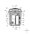
- FIG. 2 is a right side view of the cool box 1 of FIG. 1.
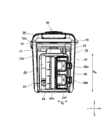
- FIG. 2 is a right side view of the cool box 1 of FIG. 1, showing a state where a cover 24 of a battery storage chamber 20 is opened.
- FIG. 5 is a partially enlarged view showing the heat exchange mechanism 50 of FIG. 4.
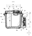
- FIG. 2 is a sectional view taken along line BB of FIG. 1.
- FIG. 3 is a sectional view taken along line DD of FIG. 2.
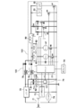
- FIG. 2 is a circuit diagram of the cool box 1 according to the embodiment of the present invention.
- FIG. 6 is a flowchart illustrating a connection operation of the microcomputer 77 in the embodiment. 6 is a graph showing a time-series change of input voltages of the battery 61, the battery 62, and the DC-DC converter 80 in the embodiment. 15 is a flowchart illustrating a connection operation of a microcomputer 77 in a modified example. 11 is a graph showing time-series changes in input voltages of a battery 61, a battery 62, and a DC-DC converter 80 in a modification. It is a side view sectional view of dust collector 201 concerning another form. It is a circuit diagram of a dust collector 201 according to another embodiment.
- FIG. 1 is a front view of a cool box 1 which is an example of a main body.
- the cool box 1 is obtained by adding a heat exchange mechanism using electric power to a so-called cooler box type container.
- pack type batteries 61 and 62 widely used for electric tools Is used as a power source to cool or heat the food and the like (hereinafter, referred to as “containment”) contained therein.
- the batteries 61 and 62 are detachably attached to the cool box 1.
- the cool box 1 has a portable structure with an internal volume of about 10 to 40 liters, for example, 25 liters.
- a Peltier element is used as a heat exchange mechanism of the cool box 1 to enable not only cooling but also warming.
- the cool box 1 includes a substantially rectangular parallelepiped container 10 having an opening on the upper side and a door 30 serving as a lid for closing the opening.
- the container portion 10 is a substantially rectangular parallelepiped, and has a shape such that only one surface (upper surface) is open, and four side walls (a front wall portion 11a and a rear wall portion 11b (see FIG.
- the front wall portion 11a and the rear wall portion 11b are arranged substantially in parallel, and the right wall portion 11c connects the right edge of the front wall portion 11a and the right edge of the rear wall portion 11b.
- 11d connects the left edge of the front wall 11a and the left edge of the rear wall 11b.
- the upper ends of the front wall 11a, the rear wall 11b, the right wall 11c, and the left wall 11d define substantially rectangular openings in plan view.
- the opening of the container 10 is closed by a door 30 that can be opened and closed with respect to the container 10.
- the door portion 30 is pivotally supported by a hinge 19 (described later with reference to FIG. 4) on one side of a long side of the opening of the container portion 10.
- Two latches 18a and 18b are provided on a long side portion (here, an upper edge portion of the front wall portion 11a) of the opening of the door portion 30 opposite to the long side portion where the hinge is provided.
- the latches 18a, 18b are manually operable lock mechanisms that are fixed to convex portions 34a, 34b (described later in FIG. 6) formed on the door portion 30 side so as to be hooked on convex portions formed on the latches 18a, 18b side.
- a known fixing member such as a patch lock or a latch can be used.
- a convex portion 14 for holding the latches 18a and 18b and forming a recess 14a for entering a hand when opening the door portion 30 is formed. Since the bottom surface of a part of the outer edge of the door portion 30 is exposed above the depression 14a, when the latches 18a and 18b are opened, the outer edge portion in front of the door portion 30 is easily pulled upward.
- Can be. 1 is in a closed state in which the opening of the container 10 is closed. When the door unit 30 is turned upward to be in the open state, the opening of the container unit 10 is opened, and the container can be stored in the storage space through the opening. Further, since the opening is closed when the door unit 30 is closed, the accommodation space 13 is in a closed state, and heat exchange by direct contact of the inside and outside air is minimized.
- a first grip 16 is formed on the left side of the opening of the container 10.
- a second grip 17 is formed on the right side of the opening of the container 10.
- the first holding part 16 and the second holding part 17 are convex parts formed for carrying while holding the vicinity of the opposite short side of the cool box 1 with both hands, and the right wall part 11c of the container part 10 and the left part are formed. It is provided near the upper part of the wall 11d.
- the first grip 16 and the second grip 17 are formed integrally with the outer surface of the container 10 made of a synthetic resin.
- Depressed portions 16a and 17a are formed on the lower surface side of the portions of the first gripping portion 16 and the second gripping portion 17 that protrude outward in the horizontal direction so that the operator can easily hold the gripping portion with both hands.
- a through-hole (not shown) for allowing the shoulder belt 65 to penetrate from top to bottom is formed near the center in the front-rear direction of the recesses 16a and 17b.
- the first grip portion 16 having the through hole is a first belt attaching portion
- the second grip portion 17 having the through hole is a second belt attaching portion.
- a single belt-like shoulder belt 65 is stretched between the first belt mounting portion and the second belt mounting portion.
- the belt adjusters 66 and 67 are members that fold back both ends of the shoulder belt 65 and penetrate the overlapped portion so that the overlapped belt does not relatively move and adjust the effective length used for the shoulder strap. is there.
- the belt adjusters 66 and 67 are integrally molded synthetic resin or metal parts, and have a shape in which three parallel elongated plate-like ends are connected by orthogonal connecting parts, and This is a shape in which two E-shaped members are prepared and joined together with their opening sides facing each other. When the belt adjusters 66 and 67 are made of a synthetic resin, they have sufficient strength.
- the shoulder belt 65 is provided with a shoulder pad 68 for dispersing a local load applied to the worker's shoulder during shouldering.
- a known pad can be used as the shoulder pad 68, and the shape and the material are arbitrary.
- a pair of casters 88a is provided near the left end of the bottom wall 12b of the container 10.
- casters 88b (not visible in FIG. 1) are provided near the corners of the rear wall portion, the left wall portion 11d, and the bottom wall portion 12b, and the casters 88a are pivotally supported by the container portion 10, and their rotation shafts 89a. Faces forward and backward.
- the rotation axis of the rear caster 88b is coaxial with the rotation axis 89a, and its axial direction is the front-back direction.
- the casters 88a and 88b do not substantially operate even if the casters 88a and 88b are installed, and the container 10 is inclined.
- the casters 88a and 88b become operable.
- the state where the casters 88a and 88b do not substantially operate means that the opposite side of the casters 88a and 88b on the lower surface of the bottom wall portion 12b is grounded, so that the horizontal movement of the container portion 10 is restricted. Including state.
- a battery storage room 20 having a second rectangular parallelepiped housing is provided on the right wall portion 11c of the container portion 10.
- the housing volume of the battery storage chamber 20 is configured to be sufficiently smaller than the housing volume of the container unit 10.
- the battery housing chamber 20 is an independent space for housing two batteries (described later) and a control circuit board (described later).
- the outer wall of the container 10 and the outer wall of the battery storage chamber 20 are manufactured by integral molding of a synthetic resin, the strength can be sufficiently increased.
- the container unit 10 as a container of the cool box and the battery storage chamber 20 for storing a power supply unit such as a battery (not shown) are formed in separate sections, so that the internal space of the container unit 10 is used for mounting the battery. The limited space can be used effectively without being squeezed.
- a heat exchange mechanism 50 (described later with reference to FIG. 5) using a Peltier element is provided in the door unit 30 that can be opened and closed.
- the container unit 10 is not provided with any main component of the heat exchange mechanism such as a fan or a heat sink. Due to the provision of the heat exchange mechanism, an intake port 35 of an outer fan, which will be described later, is provided on a part of the upper side of the door part 30, and an exhaust port 36 is provided on a part of a front side surface of the door part 30. Although not shown in FIG. 1, an exhaust port similar to the front exhaust port 36 is provided on a part of the rear side surface of the door unit 30. The air sucked into the door unit 30 from the intake port 35 is exhausted from a front exhaust port 36 and a rear exhaust port (not shown in FIG. 1).
- FIG. 2 is a right side view of the cool box 1.
- the door unit 30 has substantially the same appearance as a door unit of a commercially available cooler box, except that the door unit 30 has an intake port 35 and an exhaust port 36 (see FIG. 1) at the top.
- the battery accommodating chamber 20 arranged on the right side of the container section 10 is a casing that is smaller in the vertical direction and the front-back direction than the outer casing of the container section 10.
- the front wall 21a, the rear wall 21b, the upper wall 21c, and the lower wall 21d of the battery housing chamber 20 are connected to the right wall 11c of the container 10 so that there is no gap between them.
- An opening 21f (see FIG. 3 to be described later) is provided behind the center plane in the front-rear direction (cross section DD) of the battery storage chamber 20, and an openable cover 24 is provided to cover the opening 21f.
- the cover 24 is formed so as to extend over two surfaces from the right wall portion 21e to the rear wall portion 21b of the battery storage chamber 20, and its front edge is pivotally supported by a rotating shaft 24a whose axis extends in the vertical direction.
- the closed state is locked by two latch means, that is, the first latch 26a and the second latch 26b.
- the latch means for example, a resin patch lock that allows a movable claw to engage with a convex locking portion formed on the cover 24 side can be used.
- the first latch 26a is shown in an unlocked state and the second latch 26b is shown in a locked state for explanation.
- a power jack cover 23 that covers an opening for accessing a power jack 71 for connecting a power cord, which will be described later, is formed in a lower part of the front side of the battery housing chamber 20.
- the power jack cover 23 is an openable / closable lid that is plate-shaped, pivotally supports one side, and has a lock mechanism on the other opposite side.
- An operation display panel (not shown) is provided in a partial area 22 on the outer surface of the battery storage chamber 20.
- the operation display panel is provided with a power switch (not shown), various operation buttons (switching of cooling / heating, output mode setting), display lamps indicating an operation state, and the like.
- a flange-shaped second gripping portion 17 protruding outward in the horizontal direction is formed at an outer edge near the opening 12a at the upper end of the container portion 10.
- the second grip 17 serves as a handle for the user to grip with both hands together with the first grip 16, and has a sufficient length in the front-rear direction compared to the user's hand to make it easy to put a finger on.
- a recess 17a is formed near the center in the front-rear direction of the recess 17a.
- a through-hole (second belt mounting portion 17b) penetrated from the top to the bottom of the second holding portion 17 is provided. Is formed.
- the cross-sectional shape of the through-hole is an elongated and substantially rectangular shape, and the width WB (length in the long side direction) of the through-hole serving as the second belt mounting portion 17b is slightly larger than the width of the belt-shaped shoulder belt 65.
- the length of the short side of is larger than the thickness of the shoulder belt 65, so that the penetrating shoulder belt 65 can easily move relative to the through hole.
- a cord accommodating projection 15 that is elongated and protrudes outward is formed from the second grip 17 to the upper side wall 21c of the battery accommodation chamber 20.
- the cord accommodating convex portion 15 is formed to secure a space for wiring in an inner portion thereof.
- FIG. 3 shows a state where the cover 24 is opened from the state of FIG.
- the cover 24 is rotatable by about 180 degrees about a rotation shaft 24a.
- the rotating shaft 24a is arranged to extend in a vertical direction (up-down direction). If the axial direction (front-back direction) of the rotating shaft 89a of the casters 88a, 88b is parallel to the axial direction (vertical direction) of the rotating shaft 24a, the vibration generated around the rotating shaft 89a of the casters 88a, 88b. Since the direction and the rotation axis direction of the cover 24 are the same, the force for opening the cover 24 is repeatedly applied, and the load applied to the first latch 26a and the second latch 26b and the rotation shaft 24a increases. .
- the vibration direction generated around the casters 88a and 88b and the axial direction of the rotating shaft 24a intersect with each other. It is possible to suppress the application of force in the direction in which the opening is to be performed.
- the two batteries 61 and 62 are arranged side by side so that the mounting surface on which the connection terminals are arranged faces vertically.
- the mounting direction is from the rear side of the battery storage chamber 20 to the front side, and is mounted by moving the batteries 61 and 62 from the back to the front with the batteries 61 and 62 lying sideways.
- the length in the front-rear direction of the opening 21f is approximately half the length DB of the batteries 61 and 62 accommodated.
- the length DB is set to a length that does not hinder the operation of pressing the latch button (not shown) of the batteries 61 and 62 in a state where the user is mounted in the battery storage chamber 20.
- the height HB of the storage space inside the battery storage chamber 20 is equal to or larger than the size of two batteries so that the user can press the respective latch buttons and pull out the batteries 61 and 62. Therefore, the size is such that a predetermined space is secured around the batteries 61 and 62.
- the height HB of the accommodation space is substantially equal to the height of the opening 21f.
- a plurality of batteries can be stored in the battery storage chamber 20 and the storage space of the battery storage chamber 20 can be sealed by providing an openable and closable lid (cover 24) at the opening.
- the circuit board and the like can be completely covered, and can be protected from intrusion of dust, rainwater, and the like.
- FIG. 4 is a sectional view taken along line AA of FIG.
- the accommodating space 13 is a space for accommodating articles, and includes inner surfaces of the surrounding walls (the rear surface of the front wall portion 11a, the front surface of the rear wall portion 11b, the left surface of the right wall portion 11c, and the right and bottom surfaces of the left wall portion 11d). (The upper surface of the wall 12b).
- the outer surface and the inner surface of the wall of the container 10 are made of, for example, ABS resin, and a heat insulating material 33 such as urethane foam is filled between the outer surface and the inner surface, so that the heat insulating property in the housing space 13 is ensured.
- the door unit 30 has an outer wall 31 and an inner wall 32.
- a heat exchange mechanism 50 is provided inside the door unit 30.
- the heat exchange mechanism 50 is a cooling or heating device that removes heat in the storage space 13 and discharges it to the atmosphere, or absorbs heat in the air and discharges the heat into the storage space 13.
- the heat exchange mechanism 50 includes two Peltier elements 51 and 52, an outer heat sink 54 and an outer fan 55 arranged on the front side (outer side) of the Peltier elements 51 and 52, and the back side (inner side) of the Peltier elements 51 and 52. Side), and is mainly constituted by an inner heat sink 56 (56a to 56c) and an in-compartment fan 57.
- the batteries 61 and 62 are housed in the battery housing chamber 20 instead of the door section 30, an increase in the weight of the door section 30 can be suppressed, the center of gravity decreases, and the stability and portability of the cool box 1 can be improved.
- the heat exchange mechanism 50 but also the battery 61 may be mounted on the door unit 30.
- the door portion 30 becomes heavy, and there is a high possibility that the door portion 30 becomes difficult to open and close.
- FIG. 5 is a partially enlarged view showing the heat exchange mechanism 50 of FIG. In the inner wall 32 of the door part 30, a through hole 32a for providing a heat exchange mechanism is formed.
- the Peltier elements 51 and 52 are arranged adjacent to each other with a slight gap 53a in the front-rear direction so as to be parallel to the surface direction of the inner wall 32.
- the upper surfaces of the Peltier elements 51 and 52 commonly contact the outer heat sink 54, and the lower surfaces commonly contact the thermal conductor 56 a of the inner heat sink 56.
- the Peltier elements 51 and 52 are connected to a red cord and a black cord, respectively, which will be described later. When a current flows from the red cord to the black cord, the upper surface generates heat and the lower surface absorbs heat (the lower surface is cooled). On the other hand, when a current flows from the black cord to the red cord, the upper surface absorbs heat and the lower surface generates heat.
- the heat conductor 56a is, for example, an aluminum block, and is formed in a size corresponding to the through hole 32a.
- the outer heat sink 54 is formed by a plate-shaped base portion 54a that is in contact with the upper surfaces of the Peltier elements 51 and 52, and a fin portion 54b that includes a plurality of plate-shaped fins extending upward in the orthogonal direction from the base portion 54a. .
- the fin portion 54b extends in the front-rear direction and has a predetermined length in the vertical direction, and the outer heat sink 54 is manufactured by integral molding of a light metal such as aluminum.
- An elastic body 58 such as rubber is interposed between the base portion 54a of the outer heat sink 54 and the inner wall 32.
- An outer fan 55 is provided adjacent to the upper side of the fin portion 54b.
- the outer fan 55 is a centrifugal fan.
- the outer fan 55 rotates, the outside air is sucked in the axial direction (from the top to the bottom) from a plurality of slits 35a formed in the intake port 35, and the radial direction is indicated by an arrow AF1.
- exhausted from the exhaust port 36 see FIG. 1).
- the arrow AF1 is shown to flow backward from above, but an airflow flowing forward from above is also generated on the Peltier element 52 side.
- the inner heat sink 56 includes a heat conductor 56a, a base 56b, and fins 56c, which are manufactured by integral molding of a light metal such as aluminum.
- a plate-like base portion 56b having a large area is connected to the lower surface of the heat conductor 56a, and a plurality of plate-like fins extending in the orthogonal direction from the base portion 56b are provided below the plate-like base portion 56b. Is formed.
- the fin portion 56c extends in the front-rear direction and has a predetermined length in the vertical direction.
- An in-compartment fan 57 is formed below and adjacent to the fin portion 56c.
- a fan cover 37 made of a synthetic resin and having a plurality of wind windows (here, not visible due to the cross-sectional shape) is provided below the in-compartment fan 57 in the axial direction.
- the in-compartment fan 57 is close to the fin portion 56c, sucks the air on the upper surface of the interior of the container portion 10 from below in the axial direction, flows the air so as to sufficiently contact the fin portion 56c, and radially outwards. It is discharged as indicated by arrow AF2.
- FIG. 5 only the rearward component of the airflow AF ⁇ b> 2 is indicated by an arrow, but the airflow AF ⁇ b> 2 is similarly discharged to the front side by the inner heat sink 56.
- the cooled inner heat sink 56 removes heat from the flowing air like the AF2, thereby lowering the temperature in the refrigerator. Further, by circulating the air as indicated by the arrow AF2, the air in the refrigerator is sufficiently stirred.
- FIG. 6 is a sectional view taken along line BB of FIG.
- the outer shape of the door portion 30 is substantially rectangular when viewed from below or from above, and convex portions 34a and 34e that engage with the latches 18a and 18b are formed on one of the long sides of the outer edge (front). Near the center between the protrusions 34a and 34b, a slight depression 34c is formed for the user to put his / her hand when opening the door unit 30. At the other (rear) side of the long side of the outer edge, mounting portions 34d and 34c for fixing the hinge 19 are provided.
- a substantially half on the left side is formed with a concave part 32b depressed upward, and a substantially half on the right side is an arrangement part 41 of the heat exchange mechanism 50.
- a rotatable stopper piece 43 is provided so as to maintain an open state at a predetermined angle when the door portion 30 is opened.
- the stopper piece 43 is rotatably supported by the door portion 30 via the rotating shaft 44 at the rear, and the front side 43a is a free end, and abuts on the upper surface near the opening of the container portion 10 to slightly move the door portion 30. Can be held open.
- the Peltier elements 51 and 52 have the same size and the same standard, and are adjacent to each other with a slight gap 53a.
- the size of the base portion 54a of the outer heat sink 54 is configured to be larger than the combined size of the two Peltier elements 51 and 52.
- the red cord 51a and the black cord 51b are pulled out from the Peltier element 51 to the front side, and the red cord 52a and the black cord 52b are pulled out from the Peltier element 52 to the rear side.
- the drawn-out power cords (51a, 51b, 52a, 52b) are wired to the control circuit board 70 of the battery housing chamber 20 through the cord housing protrusions 15 (see FIG. 2).
- the direction of the cords drawn from the Peltier elements 51 and 52 is directed not to the side (right side) but to the front side or the rear side, so that the space required for wiring is reduced, and the heat conversion mechanism is provided.
- the size in the left-right direction occupied by the disposition portion 41 is set to be equal to or less than the size in the left-right direction occupied by the non-disposition portion 42 of the heat conversion mechanism.
- the red code 51a of the Peltier element 51 and the black code 51b are opposite to each other when viewed from the side 51c where the red code 51a and the black code 51b are drawn out.
- the gap 53a is arranged so as to be adjacent to the side 52d facing the side 52c from which the 52b is drawn out.
- FIG. 7 is a sectional view taken along line DD of FIG.
- the width inside the container portion 10 is W
- the distance between the side where the heat exchange mechanism 50 is housed and the side where the heat exchange mechanism 50 is not housed is made approximately equal to W / 2.
- Battery mounting portions 25a and 25b are disposed in the battery storage chamber 20 in the up and down direction.
- the battery mounting portions 25a and 25b have connection terminal portions (not shown) and are connected to connection terminals (not shown) formed on the batteries 61 and 62 side.
- a pair of guide rails (not shown) extending parallel to each other are formed on the battery mounting portions 25a and 25b.
- a control circuit board 70 is disposed in a portion of the battery storage chamber 20 closer to the container 10 than the batteries 61 and 62.
- the control circuit board 70 is arranged so that its surface direction is vertical, and a power cord to the Peltier elements 51 and 52, a power cord to the outer fan 55, a power cord to the fan 57 in the refrigerator, a temperature sensor 78 (FIG.
- a code group 59 including signal lines and the like to the door unit 30 is wired to the door unit 30.
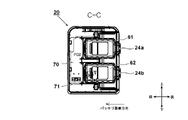
- FIG. 8 is a sectional view taken along line CC of FIG.
- the two batteries 61, 62 are arranged side by side at a predetermined distance.
- the sliding direction for mounting the batteries 61 and 62 is from the rear to the front (horizontal direction), and the direction is parallel to the axial direction of the rotating shaft 89a of the casters 88a and 88b.
- a control circuit board 70 is provided in front of the batteries 61 and 62.
- the control circuit board 70 is provided with a power supply connection portion, that is, a power supply jack 71 for enabling connection to an external power supply other than the batteries 61 and 62.
- the power jack 71 has a terminal 85b connectable to the power jack 71 at one end and a vehicle-mounted DC cord 85 having a cigar socket 85a at the other end, as shown in FIG.
- an AC-DC conversion adapter 86 can be connected by converting an AC power supply into a DC power supply.
- the AC-DC conversion adapter 86 has an outlet 86a that connects to a commercial power supply for home use (for example, AC 100 V), an adapter unit 86b that houses the AC-DC converter, and a terminal 86c that can be connected to the power jack 71.
- the equipment shown in FIG. 9 is roughly divided into a control unit 100 including a microcomputer 77, a first relay switch 75, and a second relay switch 76; a plurality of batteries 101 including a battery 61 and a battery 62; And a load 102 including the second Peltier element 52, the outer fan 55, and the internal fan 57.
- the cool box 1 includes a control unit 100 and a load 102, and has a plurality of batteries 101 detachably mounted therein.
- the cool box 1 is housed in a housing of the battery housing chamber 20 except for the Peltier elements 51 and 52,
- the electric circuit portion is mainly mounted on the control circuit board 70 (see FIG. 8).
- the cool box 1 supplies a predetermined DC current to the two Peltier elements 51 and 52 provided by using a power supply, thereby absorbing one surface of the Peltier elements 51 and 52 and causing the other surface to generate heat. .
- the amount of heat absorbed by the Peltier devices 51 and 52 is almost proportional to the magnitude of the applied voltage (V). However, if the applied voltage is too large, the amount of heat generation increases and the cooling efficiency decreases, so that about 50-60% of the maximum voltage Efficiency is increased.
- the driving of the Peltier devices 51 and 52 and the driving of the fans 55 and 57 are controlled by the microcomputer 77.
- the microcomputer 77 controls the operation of the cool box 1 and uses a commercially available one-chip type microcontroller.
- the microcomputer 77 operates at a voltage of 5 V or 3.3 V, a power supply circuit for the microcomputer 77 is not shown in FIG.
- the power supply for the microcomputer 77 is generated by a power supply circuit 79.
- the power supply circuit 79 generates the power using the power of the batteries 61 and 62 and the charging circuit 72 using a DC-DC converter such as a three-terminal regulator circuit.
- the power supply for the cool box 1 is a three-power supply system.
- One is batteries 61 and 62 arranged in the battery storage chamber 20.
- the cool box 1 can be operated even in an environment where a commercial power supply or an in-vehicle power supply cannot be obtained.
- two detachable batteries can be mounted.
- any of the connection methods of switching and controlling them, connecting them in series, or connecting them in parallel is possible.
- a switching control method is adopted, and in the case of battery driving, the microcomputer 77 selects and uses one of the battery 61 and the battery 62 in order.
- batteries 61 and 62 are connected in parallel to Peltier elements 51 and 52 serving as loads, and relay switches 75 and 76 are provided respectively. Further, diodes D1 and D2 are provided so that current does not circulate between the batteries 61 and 62. The opening and closing of the relay switches 75 and 76 are controlled by the microcomputer 77.
- the relay switches 75 and 76 are examples of a plurality of switching units.
- the microcomputer 77 uses the battery 61 first, and then uses the battery 62.
- the battery 61 is selected as a connection battery connected to the load 102, and then the battery 62 is selected as a connection battery.
- the microcomputer 77 may measure the voltage of each of the batteries 61 and 62 according to a predetermined rule, and use the battery from the battery with the higher remaining capacity or the battery with the lower remaining capacity. Alternatively, the order in which these are used may be selectable by the operator. The procedure by which the microcomputer selects a battery will be described later. Further, not only battery packs having the same standard but also batteries having different rated voltages can be mixed and mounted as the batteries 61 and 62.
- a battery having a rating of 14.4 V may be used as the battery 61, and a battery having a rating of 18 V may be used as the battery 62.
- a plurality of types of batteries can be directly connected to the battery mounting portions 25a, 25b (see FIG. 7) or the conversion adapter. It is preferable to be configured so that it can be mounted via a.
- the microcomputer 77 When selecting the battery 61 as the connection battery, the microcomputer 77 turns on the relay switch 75. Thus, the electric power of the battery 61 is supplied to the Peltier devices 51 and 52, the outer fan 55, and the internal fan 57 via the DC-DC converters 80, 81 and 82. That is, the battery 61 is connected to the load 102. While the battery 61 is selected as the connection battery, the relay switch 76 is turned off, and the connection between the battery 62 and the load is cut off. On the other hand, when the battery 62 is selected as the connection battery, the relay switch 75 is turned off and the relay switch 76 is turned on, so that the battery 61 is disconnected from the load 102 and the battery 62 is connected to the load 102 to supply power. I do.
- the control unit 100 switches connection and disconnection between each of the plurality of batteries 101 and the load 102, and each of the relay switches 75 and 76 of the control unit 100 controls the connection between the batteries 61 and 62 and the load 102. And shut off independently of each other.
- the state in which the load 102 is connected to the connected battery as described above, and the state in which the load 102 is disconnected from the remaining batteries is called a connected state, and one of the plurality of usable batteries 101 is selected as the connected battery and set to the connected state. This is called a connection operation.
- the batteries 61 and 62 contain a plurality of secondary battery cells.
- a lithium ion secondary battery is used.
- the batteries 61 and 62 have a temperature signal output terminal in addition to power supply connection terminals such as a charge plus terminal (C +), a discharge plus terminal (+), and a charge / discharge minus terminal ( ⁇ ). (T), an overcharge signal output terminal (V), a battery type determination terminal (Ls), and a battery remaining amount signal output terminal (LD).
- a part is connected to the microcomputer 77. Therefore, the microcomputer 77 can detect the type and the remaining amount of the batteries 61 and 62.
- a DC-DC converter 80 serving as a first power supply unit supplies a driving DC to the Peltier devices 51 and 52.
- a voltage of 12 V or 6 V is generated from a battery of 14.4 V, 18 V, or 12 V or more, and supplied to the Peltier devices 51 and 52.
- the "Peltier element” is a so-called electronic cooling element, which can cool one surface side by joining different metals and applying a current to the metal to make use of the principle that heat moves between the metals.
- Peltier elements have excellent durability and reliability because they have no moving parts, and are easy to handle. Further, there is no fear of gas leakage or corrosion of the refrigerant, and the handling is simple.
- the Peltier device can reverse the surface to be heated and the surface to be cooled by reversing the polarity of the applied voltage (plus or minus).
- FIG. 9 shows that the polarities of the Peltier elements 51 and 52 are fixed, a switching circuit (not shown) for inverting the polarities is interposed to keep the refrigerator cool without changing the entire configuration of the cool box 1. It can also be used as a storage.
- Switching elements M6 and M7 such as FETs (field effect transistors) are interposed in the power supply circuit to the Peltier elements 51 and 52.
- a control signal from the microcomputer 77 is input to the gates of the switching elements M6 and M7, and the microcomputer 77 shuts off one or both of the switching elements M6 and M7, and thereby both the Peltier elements 51 and 52 or One operation can be stopped.
- the resistor 1 and the resistors R3 to R5 are circuits for setting a feedback voltage (feedback voltage) FB to the DC-DC converter 80, and the resistors R3 to R5 are directly provided with semiconductor switching elements M3 to M5, respectively.
- the outputs of the microcomputer 77 are connected to the gates of the semiconductor switching elements M3 to M5, and connection or disconnection of each can be performed under the control of the microcomputer 77.
- the feedback voltage (feedback voltage) to the DC-DC converter 80 is changed by the combination of the connection and disconnection of the switching elements M3 to M5, and the output voltage from the DC-DC converter 80 to the Peltier elements 51 and 52 can be changed. is there.
- the DC-DC converter 81 is a power supply for driving the outer fan 55.
- the DC-DC converter 82 is a fan for driving the internal fan 57.
- a switching element M1 is interposed for supplying power to the outer fan 55, and a semiconductor switching element M2 is interposed for supplying power to the internal fan 57.
- the switching elements M1 and M2 can be controlled on / off by the microcomputer 77.
- a charging circuit 72 When input is made via a power supply jack 71 serving as a connection portion for an external power supply or via a DC power supply, a charging circuit 72 operates.
- the charging circuit 72 can be connected to an external power supply via a power supply jack 71, and its output is connected to batteries 61 and 62 and to DC-DC converters 80 to 82 via relay switches 75 and 76. Is also connected. Therefore, power can be supplied to the DC-DC converters 80 to 82 and the batteries 61 and 62 can be charged.
- a charge control circuit 73 is provided to control charging of the batteries 61 and 62. Specifically, the charging control circuit 73 first determines whether or not the battery 61 is fully charged, and if not, the charging circuit 72 charges the battery 61.
- the charge control circuit 73 determines whether the battery 62 is fully charged. , The charging circuit 72 charges the battery 62.
- the microcomputer 77 detects whether an external power supply is connected by the input detection circuit 74 and outputs the detection result to the microcomputer 77.
- the microcomputer 77 controls the charge control circuit 73 based on this output.
- the batteries 61 and 62 can be charged even when the relay switches 75 and 76 are both turned off. Further, since the temperature sensor 78 such as a thermistor for detecting the temperature in the refrigerator is provided, the microcomputer 77 can detect the temperature in the refrigerator.
- the microcomputer 77 optimizes the electric power supplied to the Peltier elements 51 and 52 based on the mounted state of the battery (one or two), the connection state with the external power supply, and the internal temperature (the temperature in the storage space 13). To control. At this time, the outer fan 55 and the internal fan 57 can be operated continuously irrespective of the operating state of the Peltier elements 51 and 52, so that the operation of the heat exchange mechanism 50 and the operation of the outer fan 55 and the internal fan 57 are performed. Can be controlled independently of each other, and efficient operation can be performed even with limited power from the batteries 61 and 62.
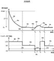
- FIG. 10 is a diagram for explaining a control method of the Peltier elements 51 and 52 in the present embodiment.
- the upper graph in FIG. 10 shows the relationship between the passage of time (unit: minute) and the internal temperature (unit: ° C.), and the lower graph shows the passage of time (unit: minute) and the supply voltage to the Peltier element ( Unit: V).
- the temperature is lowered from the outside air temperature to a temperature C2 lower by 25 ° C. (where C2 ⁇ C1).
- the temperatures C1 and C2 are controlled so as not to reach a predetermined temperature (for example, less than 5 ° C.).
- the temperature C2 is a set value when the cooling mode is “strong”, and when the cooling mode is “medium” or “small”, the set temperature difference is set small.
- the internal temperature 93 decreases as indicated by an arrow 93a, and at time t1, reaches a desired temperature C2 (here, a temperature 25 ° C. lower than the outside air temperature) as indicated by an arrow 93b.
- a desired temperature C2 here, a temperature 25 ° C. lower than the outside air temperature
- the voltage 93 applied to the Peltier elements 51 and 52 so far is constant at 12 V, and at time t1, the voltage to the Peltier elements 51 and 52 is reduced from 12 V as shown by the arrow 94a to 6V as shown by the arrow 94b.
- the generation of 6 V may be achieved by reducing the output of the DC-DC converter 80 or by a method of lowering the effective value of the voltage to 6 V by performing PWM control on the switching elements M6 and M7 (see FIG. 9). .
- the internal temperature 93 becomes substantially constant as indicated by an arrow 93c.
- it may slightly decrease as time elapses as shown by arrow 93d (it may increase). Since this temperature change state largely depends on the type, size, temperature, and the like of the items stored in the refrigerator, the temperature change as indicated by the arrow 93d is an example.
- the microcomputer 77 stops the voltage supply to the Peltier elements 51 and 52 as indicated by an arrow 94c. I do. Then, the internal temperature 93 rises as time elapses as indicated by an arrow 93f. However, when the temperature reaches a predetermined threshold value at time t4 as indicated by an arrow 93g, that is, a temperature at which power supply to the Peltier element is resumed, an arrow 94d As described above, 12 V is applied to the Peltier elements 51 and 52.
- FIG. 12 is a flowchart illustrating the connection operation of the microcomputer 77 in the present embodiment.
- the microcomputer 77 detects whether or not the battery 61 is connected to the cool box 1 in step S2, and determines whether the battery 61 is connected to the cool box 1. (S2: Yes), in step S32, the presence or absence of the battery 61 discharge completion flag is determined. The battery 61 discharged flag will be described later. If the battery 61 discharge completion flag does not exist (Step S32: No), the process proceeds to Step S34, and the battery 61 is discharged. In other words, the microcomputer 77 connects the load 102 to the battery 61 and cuts off the battery 62 in step S43.
- step 54 the microcomputer 77 determines whether or not the output voltage of the battery 61 is equal to or lower than the discharge stop voltage V2.
- the discharge stop voltage V2 is a voltage in a state immediately before the remaining capacity of the battery 61 is reduced to cause overdischarge, and is an example of an overdischarge threshold. If the output voltage of the battery 61 is higher than the discharge stop voltage V2 in step 54 (S54: No), the microcomputer 77 proceeds to step S6 to determine whether or not the battery 62 is disconnected, and the battery 62 is connected. If yes (S6: No), it is further determined in step S7 whether or not the battery 61 has been disconnected.
- step S7 If the battery 61 is still connected at step S7 (S7: No), the process returns to step S43. If the output voltage of the battery 61 is equal to or lower than the discharge stop voltage V2 in step 54 (S54: Yes), the microcomputer 77 proceeds to step S85 and sets the battery 61 discharged flag. That is, the battery 61 discharged flag is a flag indicating that the output voltage of the battery 61 is equal to or lower than the discharge stop voltage V2. The fact that the output voltage of the battery 61 is equal to or lower than the discharge stop voltage V2 is an example of a use stop condition. After setting the battery 61 discharged flag in step S85, the microcomputer 77 returns to step S2.
- step S6 If the detachment of the battery 62 is detected in step S6 (S6: Yes), the process proceeds to step S9, and if a battery 62 discharge completion flag exists, it is reset. Similarly, when the detachment of the battery 61 is detected in step S7 (S7: Yes), the process proceeds to step 10, and if the battery 61 discharge completion flag exists, it is reset. Resetting the battery 61 discharged flag and the battery 62 discharged flag 62 here means that the battery 61 discharged flag and the battery 62 discharged flag are deleted, whereby the battery 61 and the battery 62 can be used. Become.
- detachment of the batteries 61 and 62 from the cool box is an example of a reuse condition.
- the reuse condition may be such that the power jack 71 is connected to an external power source and the charging circuit 72 is supplied with power from the external power source.
- the microcomputer 77 is in the connected state in steps S43 to S5.
- step S2 If the battery 61 is not connected in step S2 (S2: NO), or if the battery 61 discharge completion flag exists in step S3 (S3: Yes), the microcomputer 77 connects the battery 62 in step S10. It is detected whether or not the battery 62 is connected (S10: Yes), and the process proceeds to step S11. If the battery 61 discharge completion flag is present in step S112 (S2: Yes), the microcomputer 77 proceeds to step S6 and determines the presence or absence of the battery 62 discharge completion flag. In other words, when the output voltage of the connected battery falls below the overdischarge threshold in step S54 in the connected state, the microcomputer 77 stores the connected battery as a use-prohibited battery and continues the connection operation.
- step S611 If the battery 62 discharge completion flag is not detected in step S611, the microcomputer 77 discharges the battery 62 in step S127, and then determines in step S138 whether the output voltage of the battery 62 is equal to or lower than the discharge stop voltage V2. . If the output voltage of the battery 62 is higher than the discharge stop voltage V2 (S138: No), the microcomputer 77 proceeds to step 714 to determine whether or not the battery 61 is disconnected, and the battery 61 is connected. In this case (S14: No), the process further proceeds to step S15 to determine whether or not the battery 62 is disconnected. If the battery 62 is also continuously connected (S15: No), the process proceeds to step S12.
- step S13 if the output voltage of the battery 62 is the discharge stop voltage V2, the process proceeds to step S169 to set the battery 62 discharge completion flag, and then returns to step S2. If detachment of the battery 61 is detected in step S14 (S14: Yes), the battery 61 discharge completion flag is reset in step S17, and the process proceeds to step S15. In step S15, detachment of the battery 62 is detected. In this case (S15: Yes), the battery 62 discharge completion flag is reset, and the process returns to step S2.
- step 19 the microcomputer 77 identifies whether or not an external power supply is connected to the power supply jack 71, and if the external power supply is connected (S54: Yes), drives the load 102 with the external power supply. When the power is not connected, the power is turned off. Note that the battery 61 discharged flag and the battery 62 discharged flag may be reset in step S55.
- the battery 61 discharged flag and the battery 62 discharged flag can be reset at any step in the flowchart of FIG. 12, in other words, at any timing during the connection operation.
- the battery 61 discharged flag is reset when the battery 61 is removed from the cool box 1 and then attached again
- the battery 62 discharged flag is removed when the battery 62 is removed from the cool box 1 and attached again. May be reset. Since there is a high possibility that the batteries 61 and 62 have been removed from the cool box 1 and have been charged and then reattached to the cool box 1, the batteries 61 and 62 that have been used after overdischarge has been resolved can be used without any problem. be able to.
- reattaching the batteries 61 and 62 after removing them from the cool box is an example of a reuse condition.
- the reuse condition may be such that the power jack 71 is connected to an external power source and the charging circuit 72 is supplied with power from the external power source.
- FIG. 13 is a graph showing an example of a time-series change of the input voltage of the battery 61, the battery 62, and the DC-DC converter 80.
- the microcomputer selects the battery 61 as a connected battery, and starts discharging the battery 61 at time t11. While discharging the battery 61, the voltage of the battery 61 decreases in accordance with the remaining capacity.
- the microcomputer 77 stores the battery 61 as a use prohibition battery, and selects the battery 62 as a connection battery.
- the microcomputer 77 stores the battery 62 as a use-prohibited battery and turns off the power.
- the batteries 61 and 62 connected to the load 102 satisfy the stop condition
- the batteries 61 and 62 are stored as unusable batteries until the batteries 61 and 62 satisfy the reuse condition. Because a configuration is used in which another battery is newly selected and used, when a battery is selected again later, a battery that is once determined to be unusable is selected and used again, and immediately after that, it is determined that the battery is unusable. Since the operation is suppressed, the operation of the cool box 1 can be stabilized. In addition, since the selection of the battery is performed by the control unit 100, the work of the operator is reduced and the workability during use is improved. Further, unnecessary operations are reduced when a battery is selected, so that power consumption is reduced and power can be used efficiently.
- FIG. 14 is a flowchart showing the connection operation of the microcomputer 77 in the modified example.
- step S23 and step S2436 are added to the present embodiment, and the other configuration is almost the same as the present embodiment. If it is determined in steps S32 to S35 that both of the batteries 61 and 62 are connected, and if neither the battery 61 discharged flag nor the battery 62 discharged flag is detected, the microcomputer 77 determines in step S36 that a voltage (not shown) The detector detects the output voltage of the battery 61 and the output voltage of the battery 62 and compares them.
- step S23 the microcomputer 77 proceeds to step S23 to identify the presence or absence of the battery 62 discharged flag. If the battery 62 discharge completion flag does not exist in step S23 (S23: Yes), the process proceeds to step S25, and the subsequent flow is the same as that in FIG. If the battery 62 discharge completion flag does not exist in step S23 (S23: No), the microcomputer 77 proceeds to step S24, and compares the output voltage of the battery 61 with the output voltage of the battery 62.
- the microcomputer 77 selects the battery with the smallest output voltage among the plurality of usable batteries 101 as the connection battery in the connection operation. According to the configuration of the present modified example, the battery having the smaller remaining capacity among the plurality of batteries 101 connected to the cool box 1 is consumed first, so that the battery 2 having the larger remaining capacity is used after the first battery is used up. The first battery can be charged for a long time while using the first battery, and the cool box 1 can be used efficiently.
- FIG. 15 is a graph showing an example of a time-series change of the input voltage of the battery 61, the battery 62, and the DC-DC converter 80 in the modification.
- the microcomputer 77 selects the battery 62 having the smaller remaining capacity from the output voltage V1 of the battery 61 and the output voltage V4 of the battery 62 as a connected battery, and starts discharging.
- the microcomputer 77 stores the battery 62 as a use prohibited battery and selects the battery 61 as a connection battery.
- the battery 62 is disconnected from the load 102
- the battery 62 is released from the load 102, so that the output voltage increases from V2 to V3.
- the microcomputer 77 stores the battery 61 as a use-prohibited battery and turns off the power.
- the electric device according to the second embodiment is a dust collector 201.
- the dust collector 201 is also an example of a main body.
- the main body has a motor 220 serving as a load, a head 210 having a dust collection fan 212 driven by the motor 211, a dust suction port 221, an opening at one side, and a tank 220 in which the head 210 is disposed at the opening 223.
- a filter 222 that is provided in the tank and filters air flowing from the suction port 221 toward the opening 223.
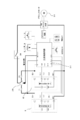
- FIG. 17 shows a circuit block diagram of the dust collector 201.
- Batteries 61 and 62 are detachably connected to the dust collector 201.
- a microcomputer 277 is provided.
- the microcomputer 277 performs a connection operation of selecting one of the battery 61 and the battery 62 and connecting to the motor 211 by switching the switching unit 275.
- the role of the microcomputer 277 is equivalent to that of the microcomputer 77.
- the connection operation and the time-series change of the output voltages of the batteries 61 and 62 are the same as those of the present embodiment shown in FIGS. 12 and 13 or the modified examples shown in FIGS.
- second grip part 17a: recessed portion, 17b: second belt mounting portion, 18a, 18b: latch, 19: hinge, 20: battery storage chamber, 21a: front wall portion, 21b: rear wall portion, 21c: upper wall, 21d: lower Side wall, 21e: Right wall, 21f: Opening, 22: Operation display panel, 23: Power jack cover, 24: Cover, 24a: Rotating shaft, 25a, 25b: Battery mounting part, 26a: First latch, 26b ... Second latch, 27, 28 ... Third belt mounting part, 3 ... door part, 31 ... outer wall, 32 ... inner wall, 32a ... through hole, 32b ... recess, 32c ... clearance, 33 ... heat insulating material, 34a ...
- Heat conductor 56b ... Base part, 56c ... Fin part, 57 ... Internal fan (Inside 58) elastic body, 59 ... cord group, 61, 62 ... battery, 65 ... shoulder belt, 66, 67 ... belt adjuster, 68 ... shoulder pad, 69 ... grip, 69a ... grip, 69b ...
- outside heat sink 155 outside fan, 157 inside fan, D1, D2 diode, M1 to M6 switching element, R1 to R5 resistance, AF1, AF2 air flow, 201 dust collector (main body), 210 ... Head, 211 ... Motor, 212 ... Dust collection fan, 220 ... Tank, 221 ... Suction port, 222 ... Filter, 223 ... Opening, 275 ... Switching unit, 2 7 ... microcomputer
Landscapes
- Engineering & Computer Science (AREA)
- Chemical Kinetics & Catalysis (AREA)
- Electrochemistry (AREA)
- General Chemical & Material Sciences (AREA)
- Chemical & Material Sciences (AREA)
- Manufacturing & Machinery (AREA)
- Computer Hardware Design (AREA)
- Biophysics (AREA)
- Life Sciences & Earth Sciences (AREA)
- Physics & Mathematics (AREA)
- Power Engineering (AREA)
- General Engineering & Computer Science (AREA)
- Thermal Sciences (AREA)
- Mechanical Engineering (AREA)
- Electric Vacuum Cleaner (AREA)
- Charge And Discharge Circuits For Batteries Or The Like (AREA)
- Direct Current Feeding And Distribution (AREA)
- Secondary Cells (AREA)
- Devices That Are Associated With Refrigeration Equipment (AREA)
Abstract
動作を安定させることができる電気機器を実現する。電力により動作する負荷と、前記負荷に電力を供給可能な複数のバッテリと、前記複数のバッテリの各々と前記負荷との接続及び遮断を切り替える制御部と、前記負荷と前記制御部とを備え、前記複数のバッテリが着脱自在に装着される本体部と、を有し、前記制御部は、使用可能な前記複数のバッテリのうち1つを接続バッテリとして選択し、前記負荷を前記接続バッテリに接続するとともに前記複数のバッテリの残りから遮断する接続状態となる接続動作を行い、前記接続状態において前記接続バッテリが所定の使用停止条件を満たすと、前記接続バッテリを所定の再使用条件が満たされるまで使用不能な使用禁止バッテリとして記憶して前記接続動作を繰り返す。
Description
本発明は、バッテリによって駆動可能な電気機器に関する。
電気機器の一例として、飲食物等を収容可能な筺体を有し、当該筐体に収容された飲食物等(収容物)を保冷可能な可搬式の可搬型保冷庫が市販されている(特許文献1)。特許文献1に記載の保冷庫は、外部電源を使用可能な場所においては、外部電源にてペルチェ素子を駆動することにより収容物を冷却する。この際、装着されているバッテリパックを充電しながらの冷却が可能である。外部電源を使用できない場所においては、充電された内部バッテリの電力を用いてペルチェ素子を駆動することで収容物を冷却する。ペルチェ素子とは、直流電流により冷却又は加熱等の温度制御を自由に行える半導体素子であり、素子の両面に温度差を発生させることができる。このペルチェ素子に直流電流を流すことにより、低温側で吸熱、高温側で発熱を起こすことができ、ペルチェ素子に与える電圧を変えることによって、ポンピングされる熱量の大きさを変えることができる。また、ペルチェ素子に流す電流の極性を変えるだけでポンピングする熱の方向を変えることができるので、保冷庫だけでなく保温庫として使用することもでき、特許文献1の技術においては保温も可能にした冷温庫としている。
特許文献1の電気機器においては、これを更に長時間駆動することが望まれた。長時間駆動するための手段としては、保冷庫本体にバッテリを複数接続可能とし、かつ、この複数のバッテリを順番にバッテリを使用する構成とすることが考えられる。これにより、駆動時間を保冷庫本体に接続されるバッテリの個数倍まで増加できるが、バッテリを複数接続して順番に使用する場合、適切にバッテリを切り替えなければ、ペルチェ素子などの負荷に与えられる電力が安定せず、不具合が生じる可能性があった。
本発明は上記背景に鑑みてなされたもので、その目的は、複数のバッテリを切り替えて使用する電気機器における動作の安定性を確保した電気機器を提供することにある。本発明の他の目的は、使用時における作業性を向上させた電気機器を提供することにある。本発明のさらに他の目的は、簡単な構成で効率的に使用可能な電気機器を提供することにある。
本願において開示される発明のうち代表的な特徴を説明すれば次のとおりである。
本発明の一つの特徴によれば、電力により動作する負荷と、前記負荷に電力を供給可能な複数のバッテリと、前記複数のバッテリの各々と前記負荷との接続及び遮断を切り替える制御部と、前記負荷と前記制御部とを備え、前記複数のバッテリが着脱自在に装着される本体部と、を有し、前記制御部は、使用可能な前記複数のバッテリのうち1つを接続バッテリとして選択し、前記負荷を前記接続バッテリに接続するとともに前記複数のバッテリの残りから遮断する接続状態となる接続動作を行い、前記接続状態において前記接続バッテリが所定の使用停止条件を満たすと、前記接続バッテリを所定の再使用条件が満たされるまで使用不能な使用禁止バッテリとして記憶して前記接続動作を繰り返す。
本発明の他の特徴によれば、前記所定の再使用条件は、前記使用禁止バッテリが前記本体から取り外された後に再度取り付けられることを含む。
本発明のさらに他の特徴によれば、前記所定の使用停止条件は、前記接続バッテリの出力電圧が所定の過放電閾値を下回ることを含む。
本発明のさらに他の特徴によれば、前記制御部は、前記接続動作において、使用可能な前記複数のバッテリのうち最も出力電圧の小さい1つを前記接続バッテリとして選択する。
本発明のさらに他の特徴によれば、前記複数のバッテリとして、2つのバッテリを有する。
本発明のさらに他の特徴によれば、外部の電源と接続可能であり、前記複数のバッテリを外部の電源から供給される電力により充電する充電回路を更に有し、前記所定の再使用条件は、前記充電回路が外部の電源から電力が供給されることを含む。
本発明のさらに他の特徴によれば、前記制御部は、前記複数のバッテリの各々と前記負荷との間に電気的に接続され、前記複数のバッテリの各々と前記負荷との接続と遮断を互いに独立して切り替える複数の切替部を有する。
本発明のさらに他の特徴によれば、前記本体部は、物品が収容される庫内を確定する容器部と、前記容器内の開口を閉鎖するドア部と、を含み、前記負荷は前記庫内を冷却するペルチェ素子である、可搬型保冷庫である。
本発明のさらに他の特徴によれば、前記負荷はモータであり、前記本体部は、前記モータにより駆動する集塵ファンを有するヘッドと、粉塵の吸込口を有するとともに一方に開口し、前記開口に前記ヘッドが配置されるタンクと、前記タンク内に設けられ、前記吸込口から前記開口に向かう空気を濾過するフィルタと、を有する、集塵機である。
本発明によれば、負荷と接続したバッテリが停止条件を満たすと、バッテリが再使用条件を満たすまで使用不能な使用禁止バッテリとして記憶したうえで新たに他のバッテリを選択して使用する構成としたため、後に再度バッテリを選択する際に、一度使用不能と判断したバッテリを再度選択して使用し、直後に使用不能と判断してしまうような動作が抑制されるため、電気機器の動作を安定させることができる。また、バッテリの選択は制御部によって行われるため、作業者の手間が少なく使用時の作業性が向上する。また、バッテリの選択時に不要な動作が少なくなるため、消費電力を低減し効率的に電力を使用可能になる。
以下、本発明の実施例を図面に基づいて説明する。なお、以下の図において、同一の部分には同一の符号を付し、繰り返しの説明は省略する。また、本明細書においては、前後、上下の方向は図中に示す方向であるとして説明する。
図1は、本体部の一例である保冷庫1の正面図である。保冷庫1は、いわゆるクーラーボックス型の容器に、電力を利用した熱交換機構を付加したものであって、ここでは電動工具用に広く用いられているパック式のバッテリ61、62(図3参照)を電源として、内部に収容された飲食物等(以下、「収容物」と呼ぶ)を冷却又は保温可能に構成した。バッテリ61、62は、保冷庫1に対して着脱自在に装着される。保冷庫1は内容積が10~40リットル程度、例えば25リットルの携帯可能な構成である。保冷庫1の熱交換機構としてはペルチェ素子を用い、冷却だけでなく保温も可能とするが、本実施例の構成を用いて冷却だけの専用の保冷庫、又は、保温だけの専用の保温庫とすることも可能である。本明細書では、保温機構の有無に関わらずに冷却機能があれば「保冷庫」と呼ぶことにする。保冷庫1は、上側に開口を有する略直方体状の容器部10に、開口を閉鎖する蓋となるドア部30を設けたものである。容器部10は略直方体であって、一面(上面)だけが開口となるような形状であり、開口を規定する4つの側壁部(前壁部11a、後壁部11b(図2参照)、右壁部11c、左壁部11d)と、容器部10の開口からみて反対側の面となる底壁部12bを有する。前壁部11aと後壁部11b(図2参照)は略平行に配置され、右壁部11cは、前壁部11aの右端縁と後壁部11bの右端縁とを接続し、左壁部11dは、前壁部11aの左端縁と後壁部11bの左端縁とを接続する。また、前壁部11a、後壁部11b、右壁部11c及び左壁部11dのそれぞれの上端部は、平面視略矩形状の開口を規定する。
容器部10の開口は、容器部10に対して開閉可能なドア部30にて閉鎖される。ドア部30は、容器部10の開口のうち、長辺の一辺側に蝶番19(図4にて後述)にて軸支される。ドア部30の開口のうち、蝶番の設けられる長辺部と反対側の長辺部(ここでは前壁部11aの上縁部)には、2つのラッチ18a、18bが設けられる。ラッチ18a、18bは、ドア部30側に形成される凸部34a、34b(図6で後述)にラッチ18a、18b側に形成された凸部に引っかけるようにして固定する手動操作可能なロック機構であり、パッチン錠、ラッチなど、公知の固定部材を用いることができる。容器部10の前壁部11aの上縁部には、ラッチ18a、18bを保持すると共に、ドア部30を開ける際の手を入れる窪み14aが形成するための凸部14が形成される。窪み14aの上側には、ドア部30の外縁の一部の底面が露出するので、ラッチ18a、18bを開放状態とした際に、ドア部30の手前の外縁部を容易に上方側に引き上げることができる。図1の状態は、容器部10の開口を閉塞している閉状態にある。ドア部30が上方に回動して開状態になると、容器部10の開口は開放され、開口を介して収容物を収容空間内に収容可能である。また、ドア部30が閉状態においては開口が閉塞されるので、収容空間13は密閉状態となり、内外気の空気の直接接触による熱交換が最小化される。
容器部10の開口の左側側方には第一把持部16が形成される。同様にして、容器部10の開口の右側側方には第二把持部17が形成される。第一把持部16と第二把持部17は、両手で保冷庫1の対向する短辺付近を把持しながら運搬するために形成される凸部であり、容器部10の右壁部11cと左壁部11dの上方付近に設けられる。第一把持部16と第二把持部17は、合成樹脂で製造される容器部10の外面と一体に成形される。第一把持部16と第二把持部17の水平方向外側に突出する部分の下面側には、作業者が両手で把持する際に持ちやすくするための窪み部16a、17aが形成される。また、窪み部16a、17bの前後方向中央付近には、肩掛けベルト65を上から下まで貫通させるための図示しない貫通孔(後述)が形成される。貫通孔が形成された第一把持部16が第一ベルト取付部となり、貫通孔が形成された第二把持部17が第二ベルト取付部となる。
第一ベルト取付部と第二ベルト取付部の間は、帯状の1本の肩掛けベルト65が掛け渡される。ベルトアジャスター66、67は、肩掛けベルト65の両端を折り返して重ねた部分を貫通させることによって、重ねたベルトが相対移動しないように固定すると共に、肩掛け用に利用する有効長さを調整する部材である。ベルトアジャスター66、67は一体成形の合成樹脂または金属製のパーツであって、3本の平行して延びる細長い板状の両端部を直交する連結部にて連結したような形状であって、アルファベットのE状の部材を2つ準備し、開口側を向かい合わせて接合したような形状である。ベルトアジャスター66、67を合成樹脂で作る場合は十分な強度を持たせる。肩掛けベルト65には肩掛け時に作業者の肩にかかる局所的な負荷を分散させるための肩パッド68が設けられる。肩パッド68は公知のものを使うことが可能であり、どのような形状、材質とするかは任意である。
容器部10の底壁部12bの左側端部付近には一対のキャスタ88aが設けられる。後方の壁部と左壁部11dと底壁部12bの角部付近にも同様にキャスタ88b(図1では見えない)が設けられ、キャスタ88aは容器部10によって軸支され、その回転軸89aは前後方向に向く。図1では図示していないが、後方側のキャスタ88bの回転軸は、回転軸89aと同軸上に位置し、その軸方向は前後方向となる。図1のように容器部10が水平に保たれた状態においては、キャスタ88a、88bが設置されていてもキャスタ88a、88bが実質的に動作しない状態にあり、容器部10を斜めにすることでキャスタ88a、88bが動作可能になる。ここで、キャスタ88a、88bが実質的に動作しない状態とは、底壁部12bの下面のうちキャスタ88a、88bの反対側が接地していることで容器部10の水平方向の移動が制限される状態を含む。
容器部10の右壁部11cには、第2の直方体状の筐体を有するバッテリ収容室20が設けられる。バッテリ収容室20の筐体容積は、容器部10の筐体容積よりも十分小さく構成される。バッテリ収容室20は、2つのバッテリ(後述)と、制御回路基板(後述)を収容するための独立した空間である。容器部10の外壁とバッテリ収容室20の外壁は、合成樹脂の一体成形により製造すると強度を十分高めることができる。このように保冷庫の容器としての容器部10と、図示しないバッテリ等の電源部を収容するバッテリ収容室20を別々の区画で構成したので、容器部10の内部空間がバッテリの装着のために圧迫されることなく、限られたスペースを有効に活用できる。
開閉可能なドア部30には、ペルチェ素子を用いた熱交換機構50(図5にて後述)が設けられる。容器部10にはファンやヒートシンク等の熱交換機構の本体構成部品はいずれも設けられない。熱交換機構を設けたためにドア部30の上側の一部には、後述する外側ファンの吸気口35が設けられ、ドア部30の前側側面の一部には排気口36が設けられる。尚、図1では見えないが、ドア部30の後側側面の一部にも前方の排気口36と同様の排気口が設けられる。吸気口35からドア部30の内部に吸引された空気は、前方の排気口36と後方の排気口(図1では見えない)から排気される。
図2は保冷庫1の右側面図である。ここでは肩掛けベルト65(図1参照)を取り外した状態を示している。ドア部30は、上部に吸気口35と排気口36(図1参照)を有する点を除き、市販されているクーラーボックスのドア部とほぼ同様の外観である。但し、ドア部30内に熱交換機構が収容されるため、ドア部30の上下方向に占める高さが大きくなる。容器部10の右側に配置されるバッテリ収容室20は、容器部10の外側筐体よりも上下方向、前後方向とも小さい筐体とされる。また、バッテリ収容室20の前壁部21a、後壁部21b、上側壁21c、下側壁21dは容器部10の右壁部11cと接合部に隙間が無いように接続される。バッテリ収容室20の前後方向中央面(D-D断面)よりも後方側には、開口部21f(後述する図3参照)が設けられ、その開口部21fを覆うために開閉式のカバー24が設けられる。カバー24はバッテリ収容室20の右壁部21eから後壁部21bに至る2面に渡るように形成され、前側縁部を鉛直方向に軸線が延びる回動軸24aによって軸支され、後壁部21bにて2つのラッチ手段、即ち第一ラッチ26aと第二ラッチ26bによって閉鎖状態がロックされる。ラッチ手段としては、例えば、カバー24側に形成された凸状の掛止部に可動式の爪部を係合させるような樹脂製のパッチン錠を用いることができる。図2では説明のために第一ラッチ26aをアンロック状態にて図示し、第二ラッチ26bをロック状態にて図示している。
バッテリ収容室20に前側の下方の一部には、後述する電源コードを接続する電源ジャック71へのアクセス用開口を覆う電源ジャックカバー23が形成される。電源ジャックカバー23は板状であって一辺を軸支し、対向する他辺にロック機構を有する開閉式の蓋である。バッテリ収容室20の外面の一部領域22には、図示しない操作表示パネルが設けられる。操作表示パネルには、図示しない電源スイッチ、各種操作ボタン(冷却/加熱の切替、出力モード設定)、稼働状態を示す表示ランプ等が設けられる。
容器部10の上端の開口12aに近い外縁部には、水平方向外側に凸状に突出するフランジ状の第二把持部17が形成される。第二把持部17は、ユーザが第一把持部16と共に両手で把持するための取っ手となるもので、ユーザの手に比べて前後方向に十分な長さを有し、指を掛けやすくするための窪み部17aが形成され、窪み部17aの前後方向中央付近には肩掛けベルト65を貫通させるために、第二把持部17の上から下まで貫通させた貫通孔(第二ベルト取付部17b)が形成される。貫通孔の断面形状は細長い略四角形であり、第二ベルト取付部17bたる貫通孔の幅WB(長辺方向の長さ)は、帯状の肩掛けベルト65の幅よりもわずかに大きくし、貫通孔の短辺の長さは肩掛けベルト65の厚さより大きくすることにより、貫通する肩掛けベルト65が貫通孔に対して容易に相対移動できるようにする。第二把持部17からバッテリ収容室20の上側壁21cにかけて細長く外側に突出するコード収容凸部15が形成される。コード収容凸部15は、その内側部分に配線のための空間を確保するために形成されるものである。
図3は、図2の状態からカバー24を開けた状態を示している。カバー24は回動軸24aを中心に約180度程度回動可能とされる。回動軸24aは鉛直方向(上下方向)に延びるように配置される。仮に、キャスタ88a、88bの回転軸89aの軸方向(前後方向)と、回動軸24aの軸方向(上下方向)が平行である場合、キャスタ88a、88bの回転軸89aを中心に発生する振動方向とカバー24の回動軸方向が同一となるためにカバー24を開けようとする力が繰り返し働くことになり、第一ラッチ26a及び第二ラッチ26bと回動軸24aにかかる負荷が高くなる。これに対して、本実施例の回動軸24aの配置では、キャスタ88a、88bを中心に発生する振動方向と回動軸24aの軸方向が交差する関係となることで、振動によってカバー24が開こうとする方向に力がかかることを抑制できる。
バッテリ61、62は、接続端子が配置される装着面が、鉛直方向に向くようにして上下に2つ並べて配置される。その装着方向はバッテリ収容室20の後方から前方側に向けてであって、バッテリ61、62を横倒しにした状態で、後方から前方に移動させることで装着される。右側面から見た際に、開口部21fの前後方向長さは、収容されるバッテリ61、62の略半分程度の長さDBとされる。この長さDBは、ユーザがバッテリ収容室20に装着された状態のバッテリ61、62の図示しないラッチボタンを押す操作に支障が無い程度の長さとする。また、バッテリ収容室20の内部の収容空間の高さHBは、ユーザがそれぞれのラッチボタンを押す操作と、バッテリ61、62を引き出す操作が可能なように、バッテリ2つ分の大きさ以上であって、バッテリ61、62の周囲に所定のスペースを確保したような大きさとする。ここでは収容空間の高さHBと、開口部21fの高さをほぼ等しくしている。本実施例では、バッテリ収容室20にバッテリを複数容可能とし、開口部分に開閉可能な蓋(カバー24)を設けることによってバッテリ収容室20の収容空間を密閉できるので、バッテリ61、62や制御回路基板等を完全に覆うことができ、粉塵や雨水等の侵入から保護できる。
図4は図1のA-A断面図である。収容空間13は、収容物を入れる空間であり、周囲の壁部の内側面(前壁部11aの後面、後壁部11bの前面、右壁部11cの左面及び左壁部11dの右面と底壁部12bの上面)によって画成される。容器部10の壁部の外面と内面は、例えばABS樹脂により構成され、外面と内面の間に発泡ウレタン等の断熱材33が充填されることにより、収容空間13内の断熱性が確保される。ドア部30には外壁31と内壁32が設けられる。ドア部30の内部には熱交換機構50が設けられる。熱交換機構50は収容空間13内の熱を奪って大気中に排出するか、又は、大気中の熱を吸収して収容空間13内に放出する冷却、又は加熱装置である。熱交換機構50は、2つのペルチェ素子51、52と、ペルチェ素子51、52の表面側(外面側)に配置される外側ヒートシンク54及び外側ファン55と、ペルチェ素子51、52の裏面側(内面側)に配置される内側ヒートシンク56(56a~56c)と、庫内ファン57によって主に構成される。本実施例ではバッテリ61、62をドア部30ではなくてバッテリ収容室20に収容したので、ドア部30の重量増加を抑制でき、重心が下がり保冷庫1の安定性や可搬性を向上できる。尚、特許文献1で開示されたように、熱交換機構50だけでなくバッテリ61をドア部30に装着するように構成することも考えられる。しかしながら、そのような構成によるとドア部30が重くなってしまい、開閉しにくくなる可能性が高い。
図5は図4の熱交換機構50を示す部分拡大図である。ドア部30の内壁32には、熱交換機構を設けるための貫通孔32aが形成される。
ペルチェ素子51、52は内壁32の面方向と平行になるように前後方向にわずかな隙間53aを有するように隣接して配置される。ペルチェ素子51、52の上面は外側ヒートシンク54に共通して当接し、下面は内側ヒートシンク56の熱伝導体56aに共通に当接する。ペルチェ素子51、52は、それぞれ後述する赤コードと黒コードが接続され、電流が赤コードから黒コードに流れた場合に、上面が発熱し、下面が吸熱する(下面が冷却される)。一方、電流が黒コードから赤コードに流れた場合に、上面が吸熱し、下面が発熱する。熱伝導体56aは、例えばアルミニウムのブロックであり、貫通孔32aに対応する大きさに形成される。ここでは貫通孔32aと熱伝導体56aの隙間32cを有するが、この隙間32cに接着性の樹脂を充填しても良い。
外側ヒートシンク54は、ペルチェ素子51、52に上面に接触される板状の基台部54aと、基台部54aから直交方向上側に延びる板状の複数のフィンからなるフィン部54bにより形成される。フィン部54bは前後方向に延び、上下方向に所定の長さを有するものであり、外側ヒートシンク54はアルミニウム等の軽金属の一体成形により製造される。外側ヒートシンク54の基台部54aと内壁32との間には、ゴム等の弾性体58が介在される。このように外側ヒートシンク54とドア部10の筐体との隙間に、弾性体58を設けることによって、キャスタ移動時の外側ヒートシンク54のがたつきを抑制できる。フィン部54bの上側には外側ファン55が隣接して設けられる。外側ファン55は遠心ファンであり、外側ファン55が回転することにより吸気口35の複数形成されたスリット35aから軸方向(上から下方向)に外気を吸引して、矢印AF1のように径方向に流して排気口36(図1参照)から排気される。この際、外気が熱せられた外側ヒートシンク54に接することにより、外側ヒートシンク54から熱を奪う。ここでは矢印AF1は上から後方向に流れるように示しているが、ペルチェ素子52側でも同様にして、上から前方向に流れる空気流が発生する。
内側ヒートシンク56は、熱伝導体56aと基台部56bとフィン部56cにより構成され、これらはアルミニウム等の軽金属の一体成形により製造される。熱伝導体56aの下面には、面積が大きい板状の基台部56bが連結され、板状の基台部56bの下方には、基台部56bから直交方向に延びる板状の複数のフィンからなるフィン部56cが形成される。フィン部56cは前後方向に延び、上下方向に所定の長さを有する。フィン部56cの下方には隣接して庫内ファン57が形成される。庫内ファン57の軸方向下側には、複数の風窓(ここでは断面形状の関係から見えない)が形成された合成樹脂製のファンカバー37が設けられる。庫内ファン57は、フィン部56cに接近しており、容器部10の庫内の上面の空気を軸方向下方から吸引して、フィン部56cに空気を十分接するように流して径方向外側に向けて矢印AF2のように排出する。図5では空気流AF2は後方に向けた成分だけを矢印で示したが、内側ヒートシンク56に前方側にも同様に排出される。冷却された内側ヒートシンク56が、AF2のように流れる空気から熱を奪うことにより庫内の温度が低下する。また、矢印AF2のような空気が循環することで、庫内の空気が十分に撹拌される。
図6は図1のB-B断面図である。ドア部30の外縁形状は下面視又は上面視で略長方形であり、外縁の長辺側の一方(前方)には、ラッチ18a、18bと係合する凸部34a、34eが形成される。また、凸部34a、34bに挟まれる中央付近には、ユーザがドア部30を開ける際に手を掛けるためのわずかな窪み34cが形成される。外縁の長辺側の他方(後方)には、蝶番19を固定する為の取付部34d、34cが設けられる。ドア部30の内壁のうち、左側の略半分は上方に窪ませた凹部32bが形成され、右側の略半分は熱交換機構50の配置部41となる。凹部32bの左側には、ドア部30を開けた際に所定の角度を隔てて開状態を保つように回動式のストッパー片43が設けられる。ストッパー片43は後方にて回動軸44を介してドア部30に軸支され、前方側43aが自由端部となり、容器部10の開口付近の上面に当接することにより、ドア部30をわずかに開いた状態にて保持できる。
図6の断面位置は、2つのペルチェ素子51、52の下面と同じ位置にある。ペルチェ素子51、52は同サイズ、同規格のものを用い、わずかな隙間53aを隔てて隣接させる。外側ヒートシンク54の基台部54aの大きさは、2つのペルチェ素子51、52を合わせた大きさよりも大きく構成される。このように1つの外側ヒートシンク54に2つのペルチェ素子51、52を配置することにより、冷却性能を向上させつつ部品点数の増加による製造コストの上昇を抑制した。ペルチェ素子51、52の2つの面の形状は正方形であって、1つの辺部から2本の電源コードが引き出される。即ち、ペルチェ素子51からは赤コード51aと黒コード51bが前方側に引き出され、ペルチェ素子52からは赤コード52aと黒コード52bが後方側に引き出される。引き出された電源コード(51a、51b、52a、52b)は、バッテリ収容室20の制御回路基板70までコード収容凸部15(図2参照)を通って配線される。ここではペルチェ素子51、52から引き出すコードの方向が、側方側(右側)でなくて、前方側又は後方側に向けることにより、配線のために必要な空間を小さくして、熱変換機構の配置部41の占める左右方向の大きさを、熱変換機構の非配置部42の占める左右方向の大きさ以下とした。
本実施例では図6のように配置して、ペルチェ素子51の赤コード51aと黒コード51bが引き出される辺部51cから見て対向する辺部51dが、ペルチェ素子52の赤コード52aと黒コード52bが引き出される辺部52cから見て対向する辺部52dと隣接するように、隙間53aを隔てて配置した。この結果、ペルチェ素子51、52を2つ並べても熱交換機構50の収容空間の占める面積の増加を抑制できる。また、ペルチェ素子51、52から引き出す電源コードの方向が、側方側(右側)には向かないが、ペルチェ素子51、52の位置を図19で示す従来例よりも右側にずらして配置したので、赤コード51a、52aと黒コード51b、52bが長くなることを抑制できる。
図7は図2のD-D断面図である。ここで、容器部10の内側の幅をWとすると、熱交換機構50の収容される側と、収容されない側の距離がW/2でほぼ等しくされる。このように構成することによって凹部32bによって庫内の最大高さH(=H1+H2)を有する部分の面積を大きく確保することができ、高さのある容器を収容するのに有利である。バッテリ収容室20には、上下に方向にバッテリ取付部25a、25bが配置される。バッテリ取付部25a、25bは図示しない接続端子部を有し、バッテリ61、62側に形成される図示しない接続端子と接続される。バッテリ取付部25a、25bにはそれぞれ平行に延びる1組の図示しないガイドレールが形成される。バッテリ収容室20のバッテリ61、62より容器部10に近い部分には、制御回路基板70が配置される。制御回路基板70はその面方向が鉛直になるように配置され、ペルチェ素子51、52への電源コード、外側ファン55への電源コード、庫内ファン57への電源コードや、温度センサ78(図9で後述)への信号線等を含むコード群59がドア部30にまで配線される。
図8は図1のC-C断面図である。2つのバッテリ61、62は所定の距離を隔てて上下に並べて配置される。バッテリ61、62の装着のためのスライド方向は、後方から前方方向(水平方向)であって、その方向はキャスタ88a、88bの回転軸89aの軸方向と平行になる向きである。バッテリ61、62の前方側には制御回路基板70が設けられる。制御回路基板70には、バッテリ61、62以外の外部電源と接続可能とするための電源接続部、即ち電源ジャック71が設けられる。電源ジャック71には、図11(A)に示すような、一端に電源ジャック71と接続可能な端子85bを有し、他端にシガーソケット85aを備える車載用DCコード85、又は、図11(B)に示すような、交流電源から直流電源に変換するものでAC-DC変換アダプタ86が接続可能である。AC-DC変換アダプタ86は、家庭用の商用電源(例えばAC100V)と接続するコンセント86aと、AC-DC変換器を収容するアダプタ部86bと、電源ジャック71と接続可能な端子86cを有する。
次に、図9を用いて保冷庫1の電気的構成を説明する。図9に示す機器は、大別すると、マイコン77及び第一リレースイッチ75、第二リレースイッチ76を含む制御部100と、バッテリ61及びバッテリ62を含む複数のバッテリ101と、第一ペルチェ素子51及び第二ペルチェ素子52、外側ファン55、庫内ファン57を含む負荷102と、を含んで構成される。保冷庫1は制御部100及び負荷102を備え、かつ、複数のバッテリ101が着脱自在に装着されており、ペルチェ素子51、52を除いてバッテリ収容室20の筐体内に収容され、マイコン77や電気的な回路部分は主に制御回路基板70(図8参照)に搭載される。保冷庫1は、電源を用いて2つ設けられたペルチェ素子51、52に所定の直流電流を供給することによって、ペルチェ素子51、52の一方の面を吸熱させて、反対の面を発熱させる。ペルチェ素子51、52の吸熱量は印加する電圧(V)の大きさにほぼ比例するが、印加電圧が大きすぎると発熱量が増えて冷却効率が低下するため、最大電圧の50-60%程度の効率が高くなる。ペルチェ素子51、52の駆動や、ファン55、57の駆動はマイコン77によって制御される。マイコン77は、保冷庫1の動作を制御するもので、市販されている1チップ型のマイクロコントローラ(microcontroller)を用いる。マイコン77は、5V又は3.3Vの電圧で動作するが、図9ではマイコン77用の電源回路の図示を省略している。マイコン77用の電源は電源回路79によって生成されており、電源回路79はバッテリ61、62及び充電回路72の電力を利用して三端子レギュレータ回路等のDC-DCコンバータを用いて生成する。
保冷庫1の電源は3電源方式とされる。一つは、バッテリ収容室20内に配置されるバッテリ61、62である。バッテリ61、62による可動を可能とすることで、商用電源や車載電源が得られないような環境下においても、保冷庫1を稼働させることが可能となる。ここではバッテリによる稼働時間を長くするために、着脱可能なバッテリを2つ装着できるようにした。バッテリを2つ用いる場合は、それらを切り替えて制御するか、直列接続するか、並列接続するかのいずれかの接続方法が可能である。本実施例では切替制御方式を採用し、バッテリ駆動の場合は、バッテリ61又はバッテリ62のいずれかをマイコン77が順に選択して使用する。そのため負荷となるペルチェ素子51、52に対してバッテリ61、62は並列に接続され、それぞれにリレースイッチ75、76が設けられる。また、バッテリ61、62間にて電流が循環しないように、ダイオードD1、D2が設けられる。リレースイッチ75、76は、マイコン77によって開閉が制御される。リレースイッチ75、76は複数の切替部の一例である。
マイコン77は、最初にバッテリ61を使用し、次にバッテリ62を使用する。換言すると、バッテリ61を負荷102に接続する接続バッテリとして選択し、次にバッテリ62を接続バッテリとして選択する。ただし、マイコン77は予め決められたルールに従って、例えば、バッテリ61、62のそれぞれの電圧を測定して、残量の高いバッテリ側から、又は、残量の低いバッテリ側から使用する順番としてもよく、これら使用する順番を作業者が選択可能な構成としても良い。マイコンがバッテリを選択する手順については、後述する。また、バッテリ61、62として同一規格のバッテリパックだけでなく、定格電圧が異なるバッテリを混在させて装着することも可能である。例えば、バッテリ61として定格14.4Vのバッテリを使用し、バッテリ62として定格18Vのバッテリを使用しても良い。但し、バッテリ収容室20のバッテリ取付部25a、25bに物理的に装着可能なものに限定されるので、バッテリ取付部25a、25b(図7参照)には複数種類のバッテリが直接、又は変換アダプタを介して装着可能なように構成すると好ましい。
マイコン77は、バッテリ61を接続バッテリとして選択すると、リレースイッチ75をオンする。これにより、バッテリ61の電力はDC-DCコンバータ80、81、82を介してペルチェ素子51、52及び外側ファン55、庫内ファン57に供給される。つまり、バッテリ61は負荷102と接続される。バッテリ61が接続バッテリとして選択されている間、リレースイッチ76はオフされ、バッテリ62と負荷との間は遮断される。一方、バッテリ62が接続バッテリとして選択されると、リレースイッチ75がオフとなり、リレースイッチ76がオンとなるため、バッテリ61は負荷102と遮断され、バッテリ62は負荷102と接続されて電力を供給する。このように、制御部100は複数のバッテリ101の各々と負荷102との接続及び遮断を切り替えており、制御部100のリレースイッチ75、76の各々は、バッテリ61、62と負荷102との接続及び遮断を、互いに独立して切り替える。尚、上記のように負荷102を接続バッテリに接続するとともに、残りのバッテリから遮断した状態を接続状態と呼び、使用可能な複数のバッテリ101のうち1つを接続バッテリとして選択し接続状態とすることを、接続動作と呼ぶ。
バッテリ61、62は、複数本の二次電池セルを収容している。本実施例では、リチウムイオン二次電池が用いられる。ここでは図示していないが、バッテリ61、62には、充電プラス端子(C+)、放電プラス端子(+)、充放電マイナス端子(-)という電源用の接続端子に加えて、温度信号出力端子(T)、過充電信号出力端子(V)、電池種判別端子(Ls)、電池残量信号出力端子(LD)の4つの制御用の信号端子を有しており、これらの信号端子のすべて又は一部がマイコン77に接続される。従ってマイコン77はバッテリ61、62の種類や残量等を検知することができる。
第一電源部となるDC-DCコンバータ80は、ペルチェ素子51、52に駆動用の直流を供給する。例えば、14.4V、18V、または12V以上のバッテリから、12Vまたは6Vの電圧を生成してペルチェ素子51、52に供給する。「ペルチェ素子」は、電子冷却素子と呼ばれるもので、異なる金属を接合して、そこに電流を流すことで熱が金属間を移動する原理を利用して、一面側を冷却することできる。ペルチェ素子は可動部分がないため耐久性や信頼性に優れ、取り扱いも簡単である。また、冷媒のガス漏れや腐食の虞もなく、取り扱いも簡単である。さらに、ペルチェ素子は、印加する電圧極性(プラス、マイナス)を反転させることによって、温める面と冷やす面を逆転させることができる。図9ではペルチェ素子51、52に流す極性が固定されているように図示しているが、極性を反転させる図示しない切替回路を介在させることによって、保冷庫1の全体構成を変えることなく温蔵庫としても用いることができる。
ペルチェ素子51、52への電力供給回路には、FET(電界効果トランジスタ)等のスイッチング素子M6、M7が介在される。スイッチング素子M6、M7のゲートにはマイコン77からの制御信号が入力され、マイコン77はスイッチング素子M6、M7のいずれか、又は、双方を遮断することによって、ペルチェ素子51、52の双方、又は、一方の稼働を停止させることができる。抵抗1と抵抗R3~R5はDC-DCコンバータ80へのフィードバック電圧(帰還電圧)FBを設定するための回路であり、抵抗R3~R5にはそれぞれ半導体スイッチング素子M3~M5が直接に設けられる。半導体スイッチング素子M3~M5のゲートには、マイコン77の出力が接続され、マイコン77による制御によりそれぞれの接続又は遮断を行うことができる。スイッチング素子M3~M5の接続または遮断の組み合わせにより、DC-DCコンバータ80へのフィードバック電圧(帰還電圧)が変更され、DC-DCコンバータ80からペルチェ素子51、52への出力電圧の変更が可能である。
バッテリ61、62の出力側には、第二電源部となるDC-DCコンバータ81と82が設けられる。DC-DCコンバータ81は、外側ファン55を駆動するための電源である。DC-DCコンバータ82は庫内ファン57を駆動するためのファンである。また、外側ファン55への電力供給にはスイッチング素子M1が介在され、庫内ファン57への電力供給には半導体スイッチング素子M2が介在される。スイッチング素子M1、M2はマイコン77によってオンオフ制御が可能である。
外部電源の接続部となる電源ジャック71を介して商用電源、又は、外部直流電源を介して入力する場合は、充電回路72が動作する。充電回路72は、電源ジャック71を介して外部の電源と接続可能であり、その出力は、バッテリ61、62に接続されると共に、リレースイッチ75、76を介してDC-DCコンバータ80~82にも接続される。従って、DC-DCコンバータ80~82への電力供給をすると共に、バッテリ61、62を充電することができる。本実施例の回路では充電制御回路73が設けられ、バッテリ61、62の充電を制御する。具体的には、充電制御回路73は最初にバッテリ61が満充電であるか否かを判断し、満充電でない場合、充電回路72がバッテリ61を充電する。バッテリ61が最初から満充電だった場合、あるいは、バッテリ61が充電により満充電となった場合には、充電制御回路73はバッテリ62が満充電であるか否かを判断し、満充電でない場合、充電回路72がバッテリ62を充電する。マイコン77は、入力検出回路74により外部電源が接続されているか否かを検出してマイコン77に出力する。この出力によってマイコン77は充電制御回路73を制御する。尚、リレースイッチ75、76を共にオフにした状態であっても、バッテリ61、62の充電も可能である。さらに、庫内の温度を検出するサーミスタ等の温度センサ78が設けられるので、マイコン77は庫内温度を検出できる。マイコン77は、バッテリの装着状態(1個か2個か)、外部電源との接続状態、庫内温度(収容空間13内の温度)に基づいてペルチェ素子51、52に供給される電力を最適に制御する。この際、ペルチェ素子51、52の稼働状況に関わらずに、外側ファン55と庫内ファン57を連続して稼働できるので、熱交換機構50の運転と、外側ファン55、庫内ファン57の運転をそれぞれ独立して制御でき、バッテリ61、62による限られた電力であっても効率の良い運転が可能となる。
図10は本実施例におけるペルチェ素子51、52の制御方法を説明する図である。図10の上側のグラフは時間の経過(単位:分)と庫内温度(単位:℃)の関係であり、下側のグラフは時間の経過(単位:分)とペルチェ素子への供給電圧(単位:V)の関係を示す。ここでは2つのペルチェ素子に同じ電圧を供給することによって、外気温から25℃低い温度C2(但しC2<C1)まで低下させる。但し、庫内温度はマイコン77によって制御されるため、温度C1、C2が所定温度(例えば5℃未満)にならないように制御される。また、温度C2は、冷却モードが“強”の場合の設定値であり、“中”や“小”の設定の場合は設定温度差が小さく設定される。
時刻t=0においてペルチェ素子の電源をオンにすると、庫内温度93が矢印93aのように低下し、時刻t1において矢印93bのように希望温度C2(ここでは外気温から25℃低い温度)に到達する。ここまでのペルチェ素子51、52へ印加する電圧93は12Vで一定であり、時刻t1においてペルチェ素子51、52への電圧を矢印94aのような12Vから矢印94bのように6Vに低下させる。この6Vの生成は、DC-DCコンバータ80の出力自体を低減させても良いし、スイッチング素子M6、M7(図9参照)をPWM制御することによって、電圧の実効値を6Vに下げる方法でも良い。時刻t1において矢印94bのように電圧を6Vに落とすと、矢印93cのように庫内温度93がほぼ一定になる。しかしながら時間の経過によって矢印93dのようにわずかに低下する場合もある(上昇する場合もありうる)。この温度変化状態は庫内に収容する収容物の種類、大きさ、温度等に大きく依存するので、矢印93dのような温度変化は一例である。
矢印93eのように時刻t2において温度が所定の閾値、即ちペルチェ素子51、52へ電力供給を停止する温度に到達したら、マイコン77は矢印94cのようにペルチェ素子51、52への電圧供給を停止する。すると時間の経過と共に庫内温度93が矢印93fのように上昇するが、矢印93gのように時刻t4において温度が所定の閾値、即ちペルチェ素子へ電力供給を再開する温度に到達したら、矢印94dのようにペルチェ素子51、52へ12Vが印加される。この際、ペルチェ素子51、52へ12Vを供給するのではなくて6Vの印加にするようにしても良いが、どちらかにするかは矢印93fの上昇速度を考慮してマイコン77が決定すれば良い。時刻t3でペルチェ素子への電力供給が再開されると、矢印93hのように庫内温度が徐々に低下する。時刻t4の時点で、温度が所定の閾値、即ちペルチェ素子51、52の電力を低下させる閾値温度に到達したら、矢印94eのようにペルチェ素子への電圧が6Vに低減させる。以下、同様の制御を繰り返す。
図12は、本実施例におけるマイコン77の接続動作を示すフローチャートである。ステップS1において図示しない電源スイッチがオンされると、マイコン77は、ステップS2にてバッテリ61が保冷庫1に接続されているか否かを検出し、バッテリ61が保冷庫1に接続されている場合(S2:Yes)、ステップS32にてバッテリ61放電済みフラグの有無を判別する。バッテリ61放電済みフラグについては後述する。バッテリ61放電済みフラグが存在しない場合(ステップS32:No)、ステップS34に移行し、バッテリ61を放電する。換言すると、マイコン77はステップS43において、負荷102をバッテリ61に接続するとともにバッテリ62から遮断する。ステップ43の後、ステップ54においてマイコン77はバッテリ61の出力電圧が放電停止電圧V2以下であるか否かを識別する。放電停止電圧V2は、バッテリ61の残容量が低下し過放電になる直前の状態における電圧であり、過放電閾値の一例である。マイコン77は、ステップ54においてバッテリ61の出力電圧が放電停止電圧V2より大きければ(S54:No)、ステップS6に移行してバッテリ62が離脱しているか否かを識別し、バッテリ62が接続されている場合(S6:No)には、さらにステップS7にて、バッテリ61が離脱しているか否かを識別する。ステップS7においてもバッテリ61が継続して接続されている場合(S7:No)、ステップS43に戻る。ステップ54においてバッテリ61の出力電圧が放電停止電圧V2以下であれば(S54:Yes)、マイコン77はステップS85に移行し、バッテリ61放電済みフラグをセットする。つまり、バッテリ61放電済みフラグは、バッテリ61の出力電圧が放電停止電圧V2以下であることを示すフラグである。尚、バッテリ61の出力電圧が放電停止電圧V2以下であることは、使用停止条件の一例である。マイコン77は、ステップS85においてバッテリ61放電済みフラグをセットした後、ステップS2に戻る。尚、ステップS6においてバッテリ62の離脱が検出されると(S6:Yes)、ステップS9に進み、バッテリ62放電済みフラグが存在する場合にこれをリセットする。同様に、ステップS7においてバッテリ61の離脱が検出されると(S7:Yes)、ステップ10に進み、バッテリ61放電済みフラグが存在する場合にこれをリセットする。ここでいうバッテリ61放電済みフラグ及びバッテリ62放電済みフラグ62をリセットするとは、バッテリ61放電済みフラグ及びバッテリ62放電済みフラグを削除することを意味し、これによりバッテリ61やバッテリ62が使用可能となる。バッテリ61及びバッテリ62が保冷庫1から離脱した後に保冷庫1に再び取り付けられた場合、バッテリ61及びバッテリ62が外部の充電器で充電された可能性が高いため、バッテリ61、62の過放電が解消され、問題なく使用することができる。この構成において、バッテリ61、62が保冷庫から離脱されることは、再使用条件の一例である。また、再使用条件は、電源ジャック71が外部の電源と接続され、充電回路72に外部の電源から電力に供給されることとしてもよい。また、尚、マイコン77は、ステップS43~S5において接続状態である。
マイコン77は、ステップS2においてバッテリ61が接続されていない場合(S2:NO)、または、ステップS3においてバッテリ61放電済みフラグが存在する場合(S3:Yes)に、ステップS10にてバッテリ62が接続されているか否かを検出し、バッテリ62が接続されていない場合(S10:Yes)にはステップS11に進む。マイコン77はステップS112においてバッテリ61放電済みフラグが存在する場合(S2:Yes)、ステップS6に移行して、バッテリ62放電済みフラグの有無を判別する。換言すると、マイコン77は、接続状態であるステップS54において接続バッテリの出力電圧が過放電閾値を下回ると、接続バッテリを使用禁止バッテリとして記憶して、接続動作を継続する。マイコン77は、ステップS611においてバッテリ62放電済みフラグが検出されない場合、ステップS127においてバッテリ62を放電した後、ステップS138にてバッテリ62の出力電圧が放電停止電圧V2以下であるか否かを識別する。マイコン77は、バッテリ62の出力電圧が放電停止電圧V2より大きい場合(S138:No)にはステップ714に移行してバッテリ61の離脱しているか否かを識別し、バッテリ61が接続している場合(S14:No)には、さらにステップS15に移行してバッテリ62が離脱しているか否かを識別し、バッテリ62も継続して接続されている場合(S15:No)には、ステップS12に戻る。戻り、ステップ13においてバッテリ62の出力電圧が放電停止電圧V2である場合ステップS169に移行してバッテリ62放電済みフラグをセットした後に、ステップ2に戻る。ステップS14においてバッテリ61の離脱が検出された場合(S14:Yes)には、ステップS17にてバッテリ61放電済みフラグをリセットしてステップS15に進み、ステップS15にてバッテリ62の離脱が検出された場合(S15:Yes)には、バッテリ62放電済みフラグをリセットして、ステップS2に戻る。また、マイコン77は、ステップ10においてバッテリ62の離脱を検出した場合(S10:No)、あるいは、ステップ2においてバッテリ61放電済みフラグを検出し(S2:Yes)、ステップ116においてバッテリ62放電済みフラグを検出した場合(S116:Yes)、保冷庫1にバッテリ61,62のいずれも接続されていないか、接続された複数のバッテリ101のすべてが使用禁止バッテリであると判断し、ステップ190に移行する。マイコン77はステップ19において、電源ジャック71に外部電源が接続されているか否かを識別して、外部電源が接続されている場合(S54:Yes)には負荷102を外部電源で駆動し、外部電源が接続されていない場合には、して電源をOFFとする。尚、ステップS55においてバッテリ61放電済みフラグとバッテリ62放電済みフラグをリセットしても良い。
尚、バッテリ61放電済みフラグとバッテリ62放電済みフラグは、図12のフローチャート中における任意のステップ、換言すると、接続動作中における任意のタイミングでリセット可能である。例えば、バッテリ61放電済みフラグはバッテリ61が保冷庫1から取り外された後に再度取り付けられた場合にリセットされ、バッテリ62放電済みフラグはバッテリ62が保冷庫1から取り外された後に再度取り付けられた場合にリセットされる構成としてもよい。バッテリ61及びバッテリ62が保冷庫1から取り外されて充電された後に保冷庫1に再び取り付けられた可能性が高いため、過放電が解消され使用可能となったバッテリ61、62を問題なく使用することができる。この構成において、バッテリ61、62が保冷庫から取り外された後に再度取り付けられることは、再使用条件の一例である。また、再使用条件は、電源ジャック71が外部の電源と接続され、充電回路72に外部の電源から電力に供給されることとしてもよい。
図13はバッテリ61、バッテリ62、及びDC-DCコンバータ80の入力電圧の時系列変化の一例を示すグラフである。バッテリ61及びバッテリ62の何れも出力電圧が満充電電圧V1である場合、マイコンはバッテリ61を接続バッテリとして選択し、時刻t11においてバッテリ61の放電を開始する。バッテリ61を放電している間、バッテリ61の電圧は残容量に合わせて低下する。時刻t12においてバッテリ61の出力電圧が放電停止電圧V2以下となると、マイコン77はバッテリ61を使用禁止バッテリとして記憶し、バッテリ62を接続バッテリとして選択する。時刻t12においてバッテリ61が負荷102から遮断されると、バッテリ61は負荷102から解放されるため、出力電圧はV2からV3へと増加する。バッテリ62も放電が進み出力電圧が放電停止電圧V2以下となると、マイコン77はバッテリ62も使用禁止バッテリとして記憶し、電源がOFFとなる。
以上説明したように、本実施例によれば負荷102と接続したバッテリ61、62が停止条件を満たすと、バッテリ61、62が再使用条件を満たすまで使用不能な使用禁止バッテリとして記憶したうえで新たに他のバッテリを選択して使用する構成としたため、後に再度バッテリを選択する際に、一度使用不能と判断したバッテリを再度選択して使用し、直後に使用不能と判断してしまうような動作が抑制されるため、保冷庫1の動作を安定させることができる。また、バッテリの選択は制御部100によって行われるため、作業者の手間が少なく使用時の作業性が向上する。また、バッテリの選択時に不要な動作が少なくなるため、消費電力を低減し効率的に電力を使用可能になる。
次に、図14及び図15を用いて、本実施例の変形例に係る電気機器の動作を説明する。図14は、変形例におけるマイコン77の接続動作を示すフローチャートである。変形例においては、本実施例に加えてステップS23およびステップS2436が追加されており、その他の構成は本実施例と大方同様である。ステップS32~35において、バッテリ61、62の両方が接続されていると判断し、かつ、バッテリ61放電済みフラグとバッテリ62放電済みフラグのいずれも検出されない場合、マイコン77はS36において、図示しない電圧検出器によって、バッテリ61の出力電圧及びバッテリ62の出力電圧を検出し、比較する。22においてバッテリ61放電済みフラグが検出された場合、マイコン77はステップS23に移行し、バッテリ62放電済みフラグの有無を識別する。ステップS23においてバッテリ62放電済みフラグが存在しない場合(S23:Yes)にはステップS25に移行し、その後のフローは図12と同様である。ステップS23においてバッテリ62放電済みフラグが存在しない場合には(S23:No)、マイコン77はステップS24に移行し、バッテリ61の出力電圧とバッテリ62の出力電圧とを比較する。マイコン77は、バッテリ61の出力電圧のほうがバッテリ62の出力電圧以下である場合(S3624:Yes)には、ステップS3725に進んで接続バッテリとしてバッテリ61を選択し、バッテリ61の出力電圧がバッテリ62の出力電圧より大きい場合(S36:No)、ステップS4729に進んで接続バッテリとして62を選択する。換言すると、本実施例の変形例においては、マイコン77は、接続動作において、使用可能な複数のバッテリ101のうち最も出力電圧の小さいバッテリを接続バッテリとして選択する。本変形例の構成によれば、保冷庫1に接続される複数のバッテリ101のうち残容量の少ないバッテリから先に消費するため、1つ目のバッテリを使い切った後に、より残容量の大きい2つ目のバッテリを使用しながら1つ目のバッテリを長時間充電できるようになり、保冷庫1を効率よく使用することができる。
図15は変形例におけるバッテリ61、バッテリ62、及びDC-DCコンバータ80の入力電圧の時系列変化の一例を示すグラフである。マイコン77は、t31においてバッテリ61の出力電圧V1とバッテリ62の出力電圧V4のうち残容量の小さいバッテリ62を接続バッテリとして選択し、放電を開始する。バッテリ62の放電が進み、出力電圧がt32においてV2まで低下すると、マイコン77はバッテリ62を使用禁止バッテリとして記憶し、バッテリ61を接続バッテリとして選択する。バッテリ62が負荷102から遮断されると、バッテリ62は負荷102から解放されるため、出力電圧がV2からV3まで増加する。バッテリ61の放電が進み、t33において出力電圧がV2まで低下すると、マイコン77はバッテリ61も使用禁止バッテリとして記憶し、電源がOFFとなる。
図16と図17は本発明の別形態に係る電気機器の動作を説明する。本別形態における電気機器は集塵機201である。集塵機201は本体部の一例でもある。本体部は、負荷であるモータ211と、モータ211により駆動する集塵ファン212を有するヘッド210と、粉塵の吸込口221を有するとともに一方に開口し、開口223にヘッド210が配置されるタンク220と、タンク内に設けられ、吸込口221から開口223に向かう空気を濾過するフィルタ222を備える。
図17は、集塵機201の回路ブロック図を示す。集塵機201にはバッテリ61、62が着脱可能に接続される。マイコン277が設けられており、マイコン277は切替部275を切り替えることで、バッテリ61とバッテリ62のいずれか一方を選択してモータ211と接続する接続動作を行う。マイコン277の役割はマイコン77と同等であり。その接続動作や、バッテリ61、62の出力電圧の時系列変化は、図12、13に示す本実施例、又は、図14、15に示す変形例と同様である。
本発明による電気機器は、上述した実施例に限定されず、特許請求の範囲に記載された発明の要旨の範囲内で種々の変更が可能である。
1,1A…冷温庫(保冷庫)、10,10A…容器部、11a…前壁部、11b…後壁部、11c…右壁部、11d…左壁部、12a…開口、12b…底壁部、13…収容空間、14…凸部、14a…窪み部、15…コード収容凸部、16…第一把持部、16a…窪み部、16b…第一ベルト取付部、17…第二把持部、17a…窪み部、17b…第二ベルト取付部、18a,18b…ラッチ、19…蝶番、20…バッテリ収容室、21a…前壁部、21b…後壁部、21c…上側壁、21d…下側壁、21e…右壁部、21f…開口部、22…操作表示パネル、23…電源ジャックカバー、24…カバー、24a…回動軸、25a,25b…バッテリ取付部、26a…第一ラッチ、26b…第二ラッチ、27,28…第三ベルト取付部、30…ドア部、31…外壁、32…内壁、32a…貫通孔、32b…凹部、32c…隙間、33…断熱材、34a…凸部、34d…取付部、35…吸気口、35a…スリット、36…排気口、37…ファンカバー、41…(熱交換機構の)配置部、42…(熱交換機構の)非配置部、43…ストッパー片、43a…前方側、44…回動軸、50…熱交換機構、51…第一ペルチェ素子、51a,52a…赤コード、51b,52b…黒コード、51c,51d,52c,52d…(ペルチェ素子の)辺部、52…第二ペルチェ素子、53a…隙間、54…外側ヒートシンク、54a…基台部、54b…フィン部、55…外側ファン、56…内側ヒートシンク、56a…熱伝導体、56b…基台部、56c…フィン部、57…庫内ファン(内側ファン)、58…弾性体、59…コード群、61,62…バッテリ、65…肩掛けベルト、66,67…ベルトアジャスター、68…肩パッド、69…グリップ、69a…把持部、69b…開口部、69c…ベルト保持部、69d…貫通穴、69e…連結部、70…制御回路基板、71…電源ジャック、72…充電回路、73…充電制御回路、74…入力検出、75…第一リレースイッチ、76…第二リレースイッチ、77…マイコン、78…温度センサ、80…DC-DCコンバータ(第一電源部)、81…DC-DCコンバータ(第二電源部その1)、82…DC-DCコンバータ(第二電源部その2)、85…車載用DCコード、85a…シガーソケット、85b…端子、86…AC-DC変換アダプタ、86a…コンセント、86b…アダプタ部、86c…端子、88a,88b…キャスタ、89a…回転軸、91,93…庫内温度、92,94…電圧、97…引き出し用リング、101…保冷庫、110…容器部、116…第一把持部、117…第二把持部、120…バッテリ収容室、130…ドア部、132b…凹部、150…熱交換機構、151…ペルチェ素子、151a…赤コード、151b…黒コード、154…外側ヒートシンク、155…外側ファン、157…庫内ファン、D1,D2…ダイオード、M1~M6…スイッチング素子、R1~R5…抵抗、AF1,AF2…空気の流れ、201…集塵機(本体部)、210…ヘッド、211…モータ、212…集塵ファン、220…タンク、221…吸込口、222…フィルタ、223…開口、275…切替部、277…マイコン
Claims (9)
- 電力により動作する負荷と、
前記負荷に電力を供給可能な複数のバッテリと、
前記複数のバッテリの各々と前記負荷との接続及び遮断を切り替える制御部と、
前記負荷と前記制御部とを備え、前記複数のバッテリが着脱自在に装着される本体部と、を有し、
前記制御部は、使用可能な前記複数のバッテリのうち1つを接続バッテリとして選択し、前記負荷を前記接続バッテリに接続するとともに前記複数のバッテリの残りから遮断する接続状態となる接続動作を行い、前記接続状態において前記接続バッテリが所定の使用停止条件を満たすと、前記接続バッテリを所定の再使用条件が満たされるまで使用不能な使用禁止バッテリとして記憶して前記接続動作を繰り返す、電気機器。 - 前記所定の再使用条件は、前記使用禁止バッテリが前記本体から取り外された後に再度取り付けられることを含む、請求項1に記載の電気機器。
- 前記所定の使用停止条件は、前記接続バッテリの出力電圧が所定の過放電閾値を下回ることを含む、請求項1又は2に記載の電気機器。
- 前記制御部は、前記接続動作において、使用可能な前記複数のバッテリのうち最も出力電圧の小さい1つを前記接続バッテリとして選択する、請求項1乃至3の何れか一項に記載の電気機器。
- 前記複数のバッテリとして、2つのバッテリを有することを特徴とする請求項1乃至4の何れか一項に記載の電気機器。
- 外部の電源と接続可能であり、前記複数のバッテリを外部の電源から供給される電力により充電する充電回路を更に有し、
前記所定の再使用条件は、前記充電回路が外部の電源から電力が供給されることを含む、請求項1乃至5の何れか一項に記載の電気機器。 - 前記制御部は、前記複数のバッテリの各々と前記負荷との間に電気的に接続され、前記複数のバッテリの各々と前記負荷との接続と遮断を互いに独立して切り替える複数の切替部を有する、請求項1乃至6のいずれか一項に記載の電気機器。
- 前記本体部は、物品が収容される庫内を確定する容器部と、前記容器内の開口を閉鎖するドア部と、を含み、
前記負荷は前記庫内を冷却するペルチェ素子である、可搬型保冷庫である、請求項1乃至7の何れか一項に記載の電気機器。 - 前記負荷はモータであり、
前記本体部は、
前記モータにより駆動する集塵ファンを有するヘッドと、
粉塵の吸込口を有するとともに一方に開口し、前記開口に前記ヘッドが配置されるタンクと、
前記タンク内に設けられ、前記吸込口から前記開口に向かう空気を濾過するフィルタと、を有する、集塵機である、請求項1乃至8のいずれか一項に記載の電気機器。
Priority Applications (2)
| Application Number | Priority Date | Filing Date | Title |
|---|---|---|---|
| JP2020535731A JP7167986B2 (ja) | 2018-08-10 | 2019-08-02 | 電気機器 |
| JP2022172757A JP2023017846A (ja) | 2018-08-10 | 2022-10-27 | 電気機器 |
Applications Claiming Priority (2)
| Application Number | Priority Date | Filing Date | Title |
|---|---|---|---|
| JP2018-151768 | 2018-08-10 | ||
| JP2018151768 | 2018-08-10 |
Publications (1)
| Publication Number | Publication Date |
|---|---|
| WO2020031889A1 true WO2020031889A1 (ja) | 2020-02-13 |
Family
ID=69415039
Family Applications (1)
| Application Number | Title | Priority Date | Filing Date |
|---|---|---|---|
| PCT/JP2019/030468 Ceased WO2020031889A1 (ja) | 2018-08-10 | 2019-08-02 | 電気機器 |
Country Status (2)
| Country | Link |
|---|---|
| JP (2) | JP7167986B2 (ja) |
| WO (1) | WO2020031889A1 (ja) |
Cited By (3)
| Publication number | Priority date | Publication date | Assignee | Title |
|---|---|---|---|---|
| EP3779331A4 (en) * | 2018-03-30 | 2021-05-19 | Koki Holdings Co., Ltd. | TRANSPORTABLE COOLER |
| JP2021132459A (ja) * | 2020-02-19 | 2021-09-09 | 株式会社マキタ | 電気機器 |
| JP2023032914A (ja) * | 2021-08-27 | 2023-03-09 | 株式会社マキタ | 電動作業機 |
Citations (2)
| Publication number | Priority date | Publication date | Assignee | Title |
|---|---|---|---|---|
| JPH11355976A (ja) * | 1998-04-09 | 1999-12-24 | Seiko Epson Corp | 電子装置 |
| JP2010236810A (ja) * | 2009-03-31 | 2010-10-21 | Sanyo Electric Co Ltd | 冷却配送台車 |
Family Cites Families (1)
| Publication number | Priority date | Publication date | Assignee | Title |
|---|---|---|---|---|
| JP3890168B2 (ja) * | 1999-08-03 | 2007-03-07 | 株式会社東京アールアンドデー | 電動装置及びその電池ユニットの充放電方法 |
-
2019
- 2019-08-02 JP JP2020535731A patent/JP7167986B2/ja active Active
- 2019-08-02 WO PCT/JP2019/030468 patent/WO2020031889A1/ja not_active Ceased
-
2022
- 2022-10-27 JP JP2022172757A patent/JP2023017846A/ja active Pending
Patent Citations (2)
| Publication number | Priority date | Publication date | Assignee | Title |
|---|---|---|---|---|
| JPH11355976A (ja) * | 1998-04-09 | 1999-12-24 | Seiko Epson Corp | 電子装置 |
| JP2010236810A (ja) * | 2009-03-31 | 2010-10-21 | Sanyo Electric Co Ltd | 冷却配送台車 |
Cited By (6)
| Publication number | Priority date | Publication date | Assignee | Title |
|---|---|---|---|---|
| EP3779331A4 (en) * | 2018-03-30 | 2021-05-19 | Koki Holdings Co., Ltd. | TRANSPORTABLE COOLER |
| JP2021132459A (ja) * | 2020-02-19 | 2021-09-09 | 株式会社マキタ | 電気機器 |
| JP7404100B2 (ja) | 2020-02-19 | 2023-12-25 | 株式会社マキタ | 電気機器 |
| JP2023032914A (ja) * | 2021-08-27 | 2023-03-09 | 株式会社マキタ | 電動作業機 |
| US12132360B2 (en) | 2021-08-27 | 2024-10-29 | Makita Corporation | Electric work machine |
| JP7660466B2 (ja) | 2021-08-27 | 2025-04-11 | 株式会社マキタ | 電動作業機 |
Also Published As
| Publication number | Publication date |
|---|---|
| JPWO2020031889A1 (ja) | 2021-09-09 |
| JP2023017846A (ja) | 2023-02-07 |
| JP7167986B2 (ja) | 2022-11-09 |
Similar Documents
| Publication | Publication Date | Title |
|---|---|---|
| JP2023017846A (ja) | 電気機器 | |
| US11296528B2 (en) | Adaptor and power station | |
| US20200335741A1 (en) | Interchangeable carriage for an energy storage and power supply device | |
| US20200132356A1 (en) | Portable Refrigerator With Rechargeable Battery Pack | |
| JP2021131227A (ja) | 可搬型保冷庫 | |
| US20100102772A1 (en) | System and Method for Storing and Releasing Energy | |
| CN103580110B (zh) | 适配器和电动工具 | |
| JP6769031B2 (ja) | 電気機器 | |
| AU2017265171B2 (en) | Expandable portable power source | |
| US12603376B2 (en) | Modular shareable battery system | |
| US20220290680A1 (en) | Adjustable fan assembly | |
| JP2009303430A (ja) | 電池パック | |
| US20240322576A1 (en) | Battery charger | |
| WO2014070858A2 (en) | Tool case system for mobile charging | |
| US20240170996A1 (en) | Autonomous electrical supply device, in particular for charging a battery | |
| WO2018101144A1 (ja) | 保温又は保冷庫 | |
| KR20100043757A (ko) | 축전지 캐리어 | |
| US11898734B2 (en) | Heat sink | |
| JP2020049092A (ja) | 電動作業機 | |
| CN119585970A (zh) | 用于给电化学储能器充电和放电的接口模块 | |
| CN222335708U (zh) | 保冷箱 | |
| JP2022018068A (ja) | 電動作業機器 | |
| US20250149674A1 (en) | Battery pack | |
| JP7660541B2 (ja) | 電気機器 | |
| RU221363U1 (ru) | Переносной накопитель и источник электроэнергии для полевых условий эксплуатации |
Legal Events
| Date | Code | Title | Description |
|---|---|---|---|
| 121 | Ep: the epo has been informed by wipo that ep was designated in this application |
Ref document number: 19848265 Country of ref document: EP Kind code of ref document: A1 |
|
| ENP | Entry into the national phase |
Ref document number: 2020535731 Country of ref document: JP Kind code of ref document: A |
|
| NENP | Non-entry into the national phase |
Ref country code: DE |
|
| 122 | Ep: pct application non-entry in european phase |
Ref document number: 19848265 Country of ref document: EP Kind code of ref document: A1 |