WO2020031850A1 - 情報処理装置 - Google Patents
情報処理装置 Download PDFInfo
- Publication number
- WO2020031850A1 WO2020031850A1 PCT/JP2019/030251 JP2019030251W WO2020031850A1 WO 2020031850 A1 WO2020031850 A1 WO 2020031850A1 JP 2019030251 W JP2019030251 W JP 2019030251W WO 2020031850 A1 WO2020031850 A1 WO 2020031850A1
- Authority
- WO
- WIPO (PCT)
- Prior art keywords
- person
- distance image
- state
- information processing
- notification
- Prior art date
- Legal status (The legal status is an assumption and is not a legal conclusion. Google has not performed a legal analysis and makes no representation as to the accuracy of the status listed.)
- Ceased
Links
Images


Classifications
-
- A—HUMAN NECESSITIES
- A61—MEDICAL OR VETERINARY SCIENCE; HYGIENE
- A61B—DIAGNOSIS; SURGERY; IDENTIFICATION
- A61B5/00—Measuring for diagnostic purposes; Identification of persons
-
- G—PHYSICS
- G06—COMPUTING OR CALCULATING; COUNTING
- G06T—IMAGE DATA PROCESSING OR GENERATION, IN GENERAL
- G06T1/00—General purpose image data processing
-
- G—PHYSICS
- G06—COMPUTING OR CALCULATING; COUNTING
- G06T—IMAGE DATA PROCESSING OR GENERATION, IN GENERAL
- G06T7/00—Image analysis
Definitions
- the present invention relates to an information processing device and an information processing method.
- the position of the bed is extracted from the distance image, the area of the person is detected, and the motion of the person is determined.
- the position of the bed is obtained from the frequency distribution of the height in the longitudinal direction and the lateral direction of the bed.
- the movement of the person is determined by detecting the position of the object with respect to a predetermined height position, such as a lying state, an upper body state, and a standing state.
- a predetermined height position such as a lying state, an upper body state, and a standing state.
- a caregiver who cares for the cared person may enter the room, or a family member of the cared person may enter the room. Then, when monitoring the cared person using the image captured by the distance image sensor described above, it is difficult to distinguish the cared person from other persons. For this reason, a specific state of the care receiver may be erroneously detected, and an erroneous notification or a necessary notification may not be performed. As a result, there arises a problem that the care receiver cannot be properly and promptly cared for.
- an object of the present invention is to provide an information processing apparatus capable of solving the above-mentioned problem, that the care recipient cannot be properly and promptly cared for.
- An information processing device includes: Distance image obtaining means for obtaining a distance image of a predetermined area, Based on the distance image, detecting means for detecting a first person in the distance image, Notifying means for determining the state of the first person detected in the distance image, and performing a predetermined notification based on the state of the first person, The notification means, when detecting the second person in the detection means while determining the state of the first person in the distance image, stops the notification, Take the configuration.
- the notifying unit when the detecting unit stops detecting the second person in the distance image from the distance image, the first person in the distance image Restarting the notification based on the state of Take the configuration.
- the notifying unit stores the state of the first person determined in the distance image when the detecting unit detects the second person in the distance image, and stops the notifying.
- the first person in the distance image based on the stored state of the first person Determine the state of the Take the configuration.
- the notifying unit when stopping the notification, when receiving a command to restart notification from the information processing terminal connected to the information processing apparatus, continues from the stored state of the first person. To determine the state of the first person in the distance image, Take the configuration.
- the notifying unit when receiving a notification restart instruction from the information processing terminal, restarts the notification stopped based on the state of the first person in the distance image, Take the configuration.
- the notifying unit stops based on a state of the first person in the distance image when a predetermined time has elapsed after the detection unit detects the second person in the distance image. Restarting the notification that Take the configuration.
- the detecting means when a predetermined time has elapsed after detecting the second person in the distance image, detects a person in the distance image as the new first person,
- the notifying unit determines a state of the first person newly detected in the distance image, and performs a predetermined notification based on the state of the first person, Take the configuration.
- An information processing method includes: Obtain a distance image of a predetermined area, Based on the distance image, detects a first person in the distance image, Determine the state of the first person detected in the distance image, perform a predetermined notification based on the state of the first person, When detecting the second person in the distance image while determining the state of the first person in the distance image, stop the notification, Take the configuration.
- a program includes: In information processing equipment, Distance image acquisition means for acquiring a distance image of a predetermined area, Based on the distance image, detecting means for detecting a first person in the distance image, A notification unit that determines the state of the first person detected in the distance image and performs a predetermined notification based on the state of the first person, The notification means, when detecting the second person in the detection means while determining the state of the first person in the distance image, stops the notification, Make things happen, Take the configuration.
- the present invention as configured above, enables appropriate and prompt care of a cared person.
- FIG. 1 is a schematic diagram illustrating a configuration of an information processing system according to a first embodiment of the present invention.
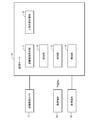
- FIG. 2 is a block diagram illustrating a configuration of a monitoring server disclosed in FIG. 1.
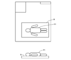
- FIG. 2 is a diagram illustrating a state of image processing by the monitoring server disclosed in FIG. 1.
- FIG. 2 is a diagram illustrating a state of image processing by the monitoring server disclosed in FIG. 1.
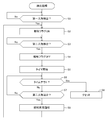
- 3 is a flowchart illustrating a processing operation of the monitoring server disclosed in FIG. 1.
- 3 is a flowchart illustrating a processing operation of the monitoring server disclosed in FIG. 1.
- FIGS. 1 and 2 are diagrams showing the configuration of the information processing system.
- 3 to 6 are diagrams for explaining the processing operation of the information processing system.
- the configuration and operation of the information processing system will be described with reference to the drawings.
- the information processing system is an information processing system for monitoring the behavior of a monitoring target person P such as a cared person or a monitored person.
- the information processing system includes a monitoring server 10, a range image camera C, a mobile terminal 20, and a monitoring terminal 30.
- the distance image camera C (photographing device) is arranged at a position where a distance image in the room R, which is an area where the bed B on which the person P to be monitored lies, is located.
- the distance image camera C is provided on a ceiling of a room R in a medical facility, a nursing facility, or a house, and is arranged at a position where most of the room R fits in the image.
- the range image camera C is not necessarily installed on the ceiling, but may be installed on any location such as a wall or a stand.
- Bed B installed in room R may be any bed such as a futon.
- the distance image camera C captures a distance image with a pixel value as a distance value.
- the range image camera C may be of a type that measures a distance from a round trip time when an infrared laser is projected onto a target, and may be any type of imaging device.
- the range image camera C has a function of shooting a range image at a fixed time interval or at a timing when a shooting instruction is received, and transmitting the range image to the monitoring server 10 described later.
- the function of the monitoring server 10 can be mounted on the range image camera C. That is, the function of the monitoring server 10 may be realized by an information processing device mounted on the range image camera C.
- the portable terminal 20 is an information processing terminal such as a smartphone that is held and operated by a user U who is a caretaker who monitors and monitors a person P1 who is a care receiver.
- the mobile terminal 20 is connected and communicable with the monitoring server 10 via wireless communication, and can input an operation instruction of the user U to the monitoring server 10 as described later.
- the mobile terminal 20 displays, on the display screen, a distance image captured by the distance image camera C, and also displays an operation screen on which an operation instruction regarding monitoring can be input.
- the operation instruction is transmitted from the mobile terminal 20 to the monitoring server 10.
- the mobile terminal 20 also has a function of receiving the notification of the state of the person P1 who is the care receiver issued from the monitoring server 10 and notifying the user U of the notification.
- the monitoring terminal 30 is an information processing terminal operated by a user U who is a monitor who monitors and monitors a person who is a care receiver.
- the monitoring terminal 30 is installed in a place such as a monitoring room where a user U such as a supervisor is enrolled, and can be operated by a plurality of users U.
- the monitoring terminal 30 displays the distance image on the display screen and enables input of an operation instruction related to monitoring similarly to the mobile terminal 20 described above, and transmits the operation instruction to the monitoring server 10 or issues the operation instruction from the monitoring server 10. It has a function of receiving the notification of the state of the person to be notified and notifying the user U of the notification.
- the monitoring server 10 is a server device (information processing device) having an arithmetic device and a storage device. As shown in FIG. 2, the monitoring server 10 includes a distance image acquisition unit 11, a detection unit 12, a determination unit 13, and a notification unit 14, which are constructed by the execution of a program by the arithmetic device. Further, the monitoring server 10 includes a person status storage unit 15 formed in a storage device.
- the function of the monitoring server 10 can be mounted on the range image camera C. That is, the function of the monitoring server 10 may be realized by an information processing device mounted on the range image camera C.
- the distance image acquisition unit 11 acquires the distance image in the room R including the bed B captured by the distance image camera C from the distance image camera C as described above. Then, by passing the acquired distance image to the detection unit 12 and the determination unit 13, the distance image is used for a person detection process and a state determination process described later.
- the detection unit 12 (detection means) first performs a process of detecting the person P1 in the distance image (Step S1 in FIG. 5).
- the detection unit 12 detects a moving object using, for example, a difference between distance images that are temporally forward and backward, and further detects a shape of the detected object (for example, whether there is an object corresponding to a pair of a head and a body). ) Is detected as the person P1.
- the detection unit 12 turns on the notification flag that is off in the initial setting (FIG. 5).
- the detection of the person P1 may be performed by any method.
- the determination unit 13 determines the state of the first person P1 by following the first person P1 detected by the detection unit 12 based on the distance image as described above (see FIG. 6). Step S11). For example, the determination unit 13 detects the height and the position of the center of gravity of the first person P1, and determines the state of the first person P1 from the positional relationship between the height and the position of the center of gravity in the distance image. Then, the determination unit 13 stores the determined state of the first person P1 in the person state storage unit 15 (step S12 in FIG. 6). At this time, the determination unit 13 stores the state of the first person P1 in association with the value of the notification flag and the time at that time.
- the determination unit 13 determines whether the state of the first person P1 is a preset detection target state based on the height, the center of gravity position of the first person P1, and the positional relationship with the bed B in the distance image. It is determined whether or not it is (step S13 in FIG. 6). When determining that the first person P1 is in the detection target state (Yes in step S13 of FIG. 6), the determination unit 13 notifies the notification unit 14 of the determination. Such determination of the state of the first person P1 is performed at regular time intervals.
- the detecting unit 12 detects the first person P1 from the distance image as shown in the upper diagram of FIG. 3 as described above, and the determining unit 13 determines the top and the center of gravity of the first person P1 as shown in the lower diagram of FIG.
- the state of the first person P1 is determined based on the positional relationship between the height of the position and the height of the bed B. For example, when the first person P1 is lying on the bed B (lying position) as shown in the lower diagram of FIG. 3, the first person P1 is lying on the bed B (position lying on the bed B). ) Is merely stored in the person state storage unit 15, and the notification to the notification unit 14 is not performed.
- the determination unit 13 determines that the first person P1 is located at the boundary of the bed B (boundary state), the first person P is standing on the bed B (standing state), and the first person P is In a state where the person P is sitting on the bed B (a state of getting up) and a state where the person P is separated from the bed B (a state of leaving the bed), the state of the first person P is detected as a detection target state, The notification unit 14 is notified.
- the detection target state determined in the present invention is not limited to the above-described state, and another state may be determined as the detection target state.
- the notification unit 14 (notification unit) receives the notification that the first person P1 has been determined to be in the detection target state from the determination unit 13 as described above (Yes in step S13 of FIG. 6), the notification flag is set. Check if it is on. At this time, if the notification flag is on (Yes in step S14 of FIG. 6), an alert notifying that the first person P is in the detection target state is output to the mobile terminal 20 or the monitoring terminal 30, and Notify the user U (step S15 in FIG. 6). At this time, the notification unit 14 may output information for notifying the content of the detection target state to the mobile terminal 20 or the monitoring terminal 30.
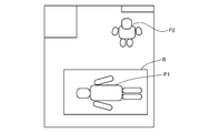
- the detection unit 12 Even after detecting the first person P1 in the distance image (Yes in step S1 in FIG. 5, step S2), the detection unit 12 further detects another person in the distance image, that is, another person in the room R.
- the detection of two persons P2 is also performed (step S3 in FIG. 5). That is, the detection unit 12 is another person such as a caregiver in the same room when the first person P1 such as a care receiver is detected and the operation of the first person P1 is detected by the determination unit 13.
- the second person P2 is detected.
- the detection of the second person P2 is performed, for example, based on the shape of an object different from the first person P1 that has been detected and the state is determined.
- the detection unit 12 turns off the notification flag set to on (step S4 in FIG. 5).
- the detection unit 12 starts measuring time by the timer (Step S5 in FIG. 5). For example, in the example of the distance image in FIG. 4, the detecting unit 12 detects the first person P ⁇ b> 1 existing in the room R first, and then detects the second person P ⁇ b> 2 entering and leaving the room R later. Becomes In this case, the notification flag is turned off, a timer is started, and the entry time of the second person P2 is measured.
- the determination unit 13 follows the first person P1 even when the second person P2 is present in the room R in addition to the first person P1, The state of the first person P1 is determined, and the storage of the determined state is continued (steps S11 and S12 in FIG. 6). On the other hand, even if the determination unit 13 determines that the state of the first person P1 is the detection target state (Yes in step S13 in FIG. 6), the notification flag is off (No in step S14 in FIG. 6). However, the above-described notification is not performed. That is, even if the determination unit 13 detects the detection target state, the notification unit 14 does not notify the notification unit 14 or the determination unit 13 notifies the notification unit 14 of the detection of the notification target state. Does not notify the monitoring terminal 30 or the like, and stops the notification. Note that, when the detection unit 12 detects the second person P2 as described above, the determination unit 13 may stop the notification by stopping the determination itself of the state of the first person P1.
- step S6 the detecting unit 12 continues until a predetermined time elapses and a timeout occurs (see FIG. 5).
- step S6 the second person P2 in the distance image is tracked, and the detection process is continued.
- step S9 the notification restart notification is sent to the determination unit 13 (step S9 in FIG. 5), and the notification flag is turned on (step S2 in FIG. 5).
- the detection unit 12 receives an instruction to restart notification from an information processing terminal such as the mobile terminal 20 or the monitoring terminal 30 connected to the monitoring server 10,
- the notification restart notification is sent to the determination unit 13.
- the detection unit 12 may send a notification restart notification to the determination unit 13 when the second person P2 cannot be detected without receiving the notification restart instruction.
- the determination unit 13 that has received the notification restart notification from the detection unit 12 continues to determine the state of the first person P1 in the distance image, but at this time, the first person P2 immediately before the second person P2 is detected.
- the state of P1 is read from the person state storage unit 15 (step S10 in FIG. 6), and the determination of the state of the first person P1 is continued from this state (step S11 in FIG. 6).
- the determination unit 13 reads the state of the first person P1 stored from the person state storage unit 15, and identifies the latest state in which the notification flag was on from the associated notification flag and time. Then, the determination of the state of the first person P1 is continued from this state, and the notification is restarted.
- the determination unit 13 may detect the timing at which the notification flag is turned off, and store the state of the first person P1 only at that time. Then, when the notification restart notification is received, the stored state of the first person P1 may be read, and the determination of the state of the first person P1 may be continued from this state.
- the detection unit 12 After detecting the second person P2 and starting the timer (step S5 in FIG. 5), the detection unit 12 times out after a preset time has elapsed (Yes in step S6 in FIG. 5). The processing so far is reset (step S8 in FIG. 5). In this case, the detection unit 12 sets a state in which no one has detected a person from the distance image, and sets the notification flag to an initial state of OFF. Then, as described above, the detection unit 12 detects a new first person P1 from within the distance image, and the determination unit 13 determines the state of the new first person P1.
- the present invention when the state of the first person P1 in the room R is determined and the second person P2 is detected in the room R, a notification based on the state of the first person P1 is issued. I'm going to stop. Thereby, it is possible to suppress the erroneous notification based on the state of the second person P2 which is not the monitoring target, and it is possible to suppress the hindrance of appropriate care.
- the notification based on the state of the first person P1 is restarted. Thereby, appropriate notification based on the state of the first person P1 is made, and quick and appropriate care can be performed.
- Non-transitory computer readable media include various types of tangible storage media. Examples of non-transitory computer-readable media are magnetic recording media (eg, flexible disk, magnetic tape, hard disk drive), magneto-optical recording media (eg, magneto-optical disk), CD-ROM (Read Only Memory), CD-R, CD-R / W, semiconductor memory (for example, mask ROM, PROM (Programmable @ ROM), EPROM (Erasable @ PROM), flash ROM, RAM (Random @ Access @ Memory)).
- the program may be supplied to the computer by various types of transitory computer readable media. Examples of transitory computer readable media include electrical signals, optical signals, and electromagnetic waves. Transitory computer readable media can provide the program to a computer via a wired communication line such as an electric wire and an optical fiber, or a wireless communication line.
- the present invention enjoys the benefit of a priority claim based on a patent application filed on Aug. 6, 2018 in Japanese Patent Application No. 2018-147328, and is described in the patent application. The contents are all included in this specification.
- Reference Signs List 10 monitoring server 11 distance image acquisition unit 12 detection unit 13 determination unit 14 notification unit 15 person status storage unit 20 mobile terminal 30 monitoring terminal B bed C distance image camera P1 first person P2 second person U user
Landscapes
- Engineering & Computer Science (AREA)
- Life Sciences & Earth Sciences (AREA)
- Physics & Mathematics (AREA)
- Health & Medical Sciences (AREA)
- General Physics & Mathematics (AREA)
- Theoretical Computer Science (AREA)
- Heart & Thoracic Surgery (AREA)
- General Health & Medical Sciences (AREA)
- Pathology (AREA)
- Biomedical Technology (AREA)
- Computer Vision & Pattern Recognition (AREA)
- Medical Informatics (AREA)
- Molecular Biology (AREA)
- Surgery (AREA)
- Animal Behavior & Ethology (AREA)
- Biophysics (AREA)
- Public Health (AREA)
- Veterinary Medicine (AREA)
- Measuring And Recording Apparatus For Diagnosis (AREA)
- Image Processing (AREA)
- Image Analysis (AREA)
- Alarm Systems (AREA)
- Emergency Alarm Devices (AREA)
Applications Claiming Priority (2)
| Application Number | Priority Date | Filing Date | Title |
|---|---|---|---|
| JP2018-147328 | 2018-08-06 | ||
| JP2018147328A JP7095870B2 (ja) | 2018-08-06 | 2018-08-06 | 情報処理装置 |
Publications (1)
| Publication Number | Publication Date |
|---|---|
| WO2020031850A1 true WO2020031850A1 (ja) | 2020-02-13 |
Family
ID=69415351
Family Applications (1)
| Application Number | Title | Priority Date | Filing Date |
|---|---|---|---|
| PCT/JP2019/030251 Ceased WO2020031850A1 (ja) | 2018-08-06 | 2019-08-01 | 情報処理装置 |
Country Status (2)
| Country | Link |
|---|---|
| JP (1) | JP7095870B2 (enExample) |
| WO (1) | WO2020031850A1 (enExample) |
Cited By (1)
| Publication number | Priority date | Publication date | Assignee | Title |
|---|---|---|---|---|
| CN115410143A (zh) * | 2021-05-26 | 2022-11-29 | 精工爱普生株式会社 | 报知方法、信息处理装置、显示系统 |
Families Citing this family (2)
| Publication number | Priority date | Publication date | Assignee | Title |
|---|---|---|---|---|
| JP6835270B1 (ja) * | 2020-02-17 | 2021-02-24 | 王子ホールディングス株式会社 | 硫酸エステル化繊維状セルロース、組成物、シート及び硫酸エステル化繊維状セルロースの製造方法 |
| JP7563401B2 (ja) * | 2022-02-15 | 2024-10-08 | コニカミノルタ株式会社 | 見守り監視システム、見守り監視方法、および見守り監視プログラム |
Citations (2)
| Publication number | Priority date | Publication date | Assignee | Title |
|---|---|---|---|---|
| WO2016152428A1 (ja) * | 2015-03-26 | 2016-09-29 | コニカミノルタ株式会社 | 被監視者監視装置および被監視者監視方法 |
| WO2017061371A1 (ja) * | 2015-10-06 | 2017-04-13 | コニカミノルタ株式会社 | 行動検知システム、行動検知装置、行動検知方法、および行動検知プログラム |
-
2018
- 2018-08-06 JP JP2018147328A patent/JP7095870B2/ja active Active
-
2019
- 2019-08-01 WO PCT/JP2019/030251 patent/WO2020031850A1/ja not_active Ceased
Patent Citations (2)
| Publication number | Priority date | Publication date | Assignee | Title |
|---|---|---|---|---|
| WO2016152428A1 (ja) * | 2015-03-26 | 2016-09-29 | コニカミノルタ株式会社 | 被監視者監視装置および被監視者監視方法 |
| WO2017061371A1 (ja) * | 2015-10-06 | 2017-04-13 | コニカミノルタ株式会社 | 行動検知システム、行動検知装置、行動検知方法、および行動検知プログラム |
Cited By (1)
| Publication number | Priority date | Publication date | Assignee | Title |
|---|---|---|---|---|
| CN115410143A (zh) * | 2021-05-26 | 2022-11-29 | 精工爱普生株式会社 | 报知方法、信息处理装置、显示系统 |
Also Published As
| Publication number | Publication date |
|---|---|
| JP2020024480A (ja) | 2020-02-13 |
| JP7095870B2 (ja) | 2022-07-05 |
Similar Documents
| Publication | Publication Date | Title |
|---|---|---|
| US10102730B2 (en) | Monitoring apparatus for monitoring a targets exposure to danger | |
| JP5924820B2 (ja) | トイレ見守り方法およびこれに用いるトイレ見守り装置 | |
| WO2020031850A1 (ja) | 情報処理装置 | |
| WO2016186160A1 (ja) | 画像処理システム、画像処理装置、画像処理方法、および画像処理プログラム | |
| US20180140230A1 (en) | Motion detection system, motion detection device, motion detection method, and motion detection program | |
| WO2019163561A1 (ja) | 情報処理装置 | |
| JP7232497B2 (ja) | 情報処理装置 | |
| WO2019240196A1 (ja) | 情報処理装置 | |
| JPWO2018030024A1 (ja) | 見守りシステム、見守り装置、見守り方法、および見守りプログラム | |
| JP2018063641A (ja) | 記録媒体、コンピュータ、ビーコンユニット及び見守りシステム | |
| JP2022126071A (ja) | 画像処理方法 | |
| JP2017076938A (ja) | 情報処理装置 | |
| JP2021033379A (ja) | 画像処理システム、画像処理プログラム、および画像処理方法 | |
| TWI577277B (zh) | 具自動異常判定之餵食裝置、系統和方法 | |
| JP7607319B2 (ja) | 画像処理方法 | |
| JP2019219171A (ja) | 情報処理装置 | |
| JP7607320B2 (ja) | 画像処理方法 | |
| WO2020021897A1 (ja) | 情報処理装置 | |
| JP6807247B2 (ja) | 監視システム、及び監視方法 | |
| JP6549524B2 (ja) | 小型基地局 | |
| US20250260791A1 (en) | Non-transitory computer-readable recording medium, watching system, and control device | |
| JP7538514B2 (ja) | 情報処理システム | |
| JP2019146712A (ja) | 行動監視システム、及び、行動監視方法 | |
| JP3215201U (ja) | 監視装置 | |
| WO2024090466A1 (ja) | 見守りシステム及び制御装置 |
Legal Events
| Date | Code | Title | Description |
|---|---|---|---|
| 121 | Ep: the epo has been informed by wipo that ep was designated in this application |
Ref document number: 19847387 Country of ref document: EP Kind code of ref document: A1 |
|
| NENP | Non-entry into the national phase |
Ref country code: DE |
|
| 122 | Ep: pct application non-entry in european phase |
Ref document number: 19847387 Country of ref document: EP Kind code of ref document: A1 |